
. .
_.
l
4:. f NEACRP-A-975
Fuel Management Effects on the Inherent Safety of
Modular High Temperature Reactor .
Yukinori HIROSE +, Peng Hong LIDI, Eiichi SUETO>lI,
Tohru OBARA and Hiroshi SEKIMOTO
Research Laboratory for Nuclear Reactors,
Tokyo Institute of Technology l
+ Present address : Nippon $izomic Indcstry Gro>~.!r Co.,'Ltd., 1.
to be published in J. of~Nuc1. Sci. Technol.

ABSTRACT
Analysis was performed on the effects of fuel loading
schemes and fuel materials on the inherent (passive) safety
characteristic of the modular pebble-bed type high-temperature
reactor against depressurization accident involving loss of
helium forced circulation. Two extreme fuel loading schemes, the
infinite-velocity multipass and Once-Through-Then-Out (OTTO),
were evaluated for both uranium and thorium fuel cycles. The
results of th2 analysis show that the maximum core temperatures
attained following the accident xere much lover for the infinite-
velocity multipass scheme than for the OTTO scheme. For both
schemes, the thorium cycle showed slightly higher maximum peak
temperatures, compared to uranium cyc1.e.
KEY \YORDS : fuel management. modular high-tenserature reactor,
inherent safety, depressurization accident, loss of helium forced
circuletion, OTTO, infinite-velocity mUltipaSS. fUel:CyCle,
equilibrium condition, maximum core temperature
15200002 i

I. INTRODUCTION
As an inherently safe reactor, the modular high temperature
reactor was proposed through development of the pebble-bed
reactor. The inherent or passive safety for the high-temperature
reactor can be stated as the capability of the reactor to limit
the maximum fuel temperature to the values for which the fission
.product release will increase the fission product inventory in
the primary circuit by factors, but not by order of magnitude (1)
The well known TRISO particles with silicon-carbide (Sic) layer
comfily \i-ith this requirement for temperatures up to 15OO'C. in
other tvords, providing the modular HTR design with passive safety
property means limiting the maximum fuel temperature below 16OO'C
during the accidents.
One essential determinant of maximum fuel temperatures for a
pebble-bed reactor is the in-core fuel management. This involves
numerous parameters such as choice of fuel loading scheme, fuel
material, etc.
In the present paper, the above two parameters were
considered. Concerning the first, two extreme fuel leading
schemes, infinite-velocity multipass and Once-Through-Then-Out
(OTTO), !vere considered. For the fuel material parameter, lolc
enriched uranium fuel and thorium with 233. L' fuel, were compared.
II. FUEL LOADIXG SCHEYES AND ACCIDEXT COSDITIONS ;
In pebble-bed reactors, fuel balls are loaded from the top
2

of the reactor, flow through the core and are discharged from the
bottom. The fuel ball loading schemes commonly used for the
pebble-bed reactor may be classified into multipass and OTTO
schemes. For the multipass scheme, the fuel balls flow through
the reactor numerous times before being finally discharged. But
for the OTTO scheme, the fuel balls transit the core only once.
The OTTO scheme may attain a nearly exponential axial power
profile with the aim of fuel temperature flattening. For both
0 multipass and OTTO schemes, the ball flow velocities affect the
nuclide density distributions, neutron flux, burn-up, .and in turn
the power and temperature profiles. With slower ball flow
velocities, the power peak shifts to the upper part of the core.
This effect is greater for the OTTO scheme. If the velocities
become infinite for the multipass scheme, the power peak becomes
broader and occurs at the center. For the usual multipass
scheme, the ball velocity is slow and the power peak appears in
the upper part of the core showing the characteristics between
the OTTO and infinite-velocity multipass schemes.
0 From the above, investigations were carried out on the OTTO
'.. L and infinite-velocity multipass fuel loading schemes. The
inherent safety characteristics mere evaluated foi each scheme
during the depressurization accident involving 10~'s of helium
forced circulation after the equilibrium condition. YFurthermore,
two kinds of fuel material - low enriched uranium dioxide and
thorium with 233U dioxide - were also investigated'for each
fuel loading scheme.
15200004

It should be noted that for the infinite-velocity multipass
loading scheme, the ball flow velocities are large enough that
they can be assumed to be infinite. For this loading scheme the
nuclide densities can be treated to be spatially uniform. The
accuracy of this assumption was investigated at the start of the
present study. For the OTTO loading scheme, all nuclides are
treated space-dependently, since the ball flow velocities are
relatively slow. The details of the OTTO cycle burn-up
simulation are presented in reference (2) .
After the accident, the reactor becomes subcritical by its
negative temperature coefficient reactivity feedback, but the
cooling power of the helium goes down through the
depressurization of the helium coolant. Decay heat is removed
only by conduction inside and betii.een fue~l balls, radiative
cooling, natural convection of helium, and conduction through the
graphite reflector into surrounding sections.
0
III. CALCULATIONAL PROCEDURE
Based on the conditions stated in the preceding section, the 0
following calculations were performed for both OTTO and infinite-
velocity multipass schemes.
1. The Equilibrium Condition of the Core
Search of the equiiibrium condition of the core’(density
distribution for each nuclide, neutron flux distribution for each
4
15200005

energy group, and power distribution) is necessary to obtain
information about the initial conditions prior to the accident.
Considering the fuel ball motion through the core, the
simulated burn-up equation for the OTTO cycle can be written as
fallows(2) :
dN. --v--l +- c A. ai'AiNi'+ c C,ui',a,gPi'-ti,gNi'6g + ds it I' g 1
C 2 z I
G~,,~,~~~,+N~,$~ - hiNi - C ~~ a ,NiGjo= 0 0 g I90 0 (1)
where
Xi(s) : Atomic density of isotope i at position s
S : Distance measured along fuel ball stream line
v : Ball speed
‘i G.
1 ,a,g a. l'+i
T., I -fl,g
@g(s)
Decay constant of isotope i
Absorption cross-section of isotope i for energy group g
Probability that decay of isotope i"produces isotope i
Probability that neutron absorption in isotope i'
produces isotope i
Yield of isotope i due to fission in isotope i' 1.
Neutron flux in energy group g at position s'
Fo: the infinite-velocity multipass scheme, the first term of the
Eq. (1) is removed, and Xi(s) becomes independent of, s.
The neutron transport problem ~2s treated 2s err r-z two-
dimens,ional four group diffusion problem. The group' constants
and their self-shielding'factors 2s a function of temperature
5
15200006

and atomic density were prepared using a part of VSOP code
system(3' (ZUT-DGL. THERMOS, and GM).
2. Steady State Temperature Distribution
After the nuclide densities and neutron flux distributions
for the equilibrium cycle were calculated, thermal-hydraulic
calculation was performed to obtain the temperature distribution
in the core for this equilibrium condition, which-was used as an
initial condition in the accident analysis.
In the normal condition, helium coolant enters the core from
: the upper part of the core, flows throug:l the voids among fuel
bails, and exits from the bottom part of the core.
Considering the spherical shape of the fuel and the void
fraction of the core, an effective coolant flow was modelled. In
this model, within the core the coolant flow through the virtual
flow channels without cross-flow, and in a particular virtual
flow channel the mass flow is assumed to be constant.
For the momentum equation, Ergun equation (4) , which is based
on Slake-Kozeny eqiiation for laminar flow and Burke-Plummer :' i
equation for turbulent flow, was used : r'
where
P': Coolant pressure
G : Mass flow rate for virtual flow channel
6

0, : Coolant mass density
n : Coolant viscosity
g : Gravitational acceleration
c : Void fraction of the core
D P
: Fuel ball diameter
In the core the heat transfer processes involved are (1)
forced convective heat transfer between fuel ba-11s and heliun
0 coolant:. (2) radiative heat transfer between the adjacent fuei
balls, (3) heat conductions inside the fuel balls and ($1 heat
convections in x:he helium coolant. Considering these heat
transfer’processos the oyerall effective heat transfer
coefficient between helium coolant and fuel balls was obtained
and used for the energy balance equation. The energy balance
equation in the fuel can be expressed as :
I a L-k
F cl-&) --- r ai DiJ
h (Ts-T,,) - Q = 0
(3)
where
0 kp : Effective conductivity inside the fuel bell
h : Forced convective heat transfer coefficient ,between .
fuel b2lls and helium coolent
4 : ?Owei density
T. 0 : Eelium bulk temperature
TS : Fuel ball surface temperature
For the coolant, the energy balance equation can be
5

expressed similarly as :
a -i-G T- dz Tb- ’ (lD-‘) h (Ts-Tb) = 0 (4)
where P
k b,r : Coolant effective conductivity in the radial
directicn
k b,z : C0012;;t effec*iv= * - conductivity in the a;iel
direction
Using the equilibrium condition as the initial condition,
the fission products and othe: radiative nuclides distributions,
and the corresponding decay heat’distribution e~fter a
depressurization accident involving loss of helium forced
circulation were calculated. For the fission-products yield
calculation, JSDC FP Decay and Yield Data xere used (3)
After the depressurization accident, the helium
flow velocity was assumed to be practically zero and helium
pressure was also assumed to be equal to the atmospheric
siressure.
The temperature for the mixture of helium coolant and fuel
balls was calculated from the helium temperature and the surface
temperature of the balls.
P&T~~ (1 -&) + pbCpbTpb& Tmx =
PpCpp (1 -E) +PbCpb&
(5) vii th
where
T ms
*P
Pb C
FP C pb T PC T
Pb k
q T =T+- PZ s GOk .DP
: Nisture temperature
: >!ass density of the ball
: Ness density of helium
: Specific heat for cosstanz pressure of the bali
: Specific heat for co:,stac: pressure of helium
: Average temperature cf th? ball
: Bulk temperature of heiium
: Heat conductivity of xhe ball
Finally, xhe heat transfer equation to be solved was
expressed as the follorving :
0 where
k’e : Effective conductivity of the core during the
accident
9 : Decas- heat production during the accident
IV. C.ALCtiLATED RESULTS ASD DISCUSSION
(6)
The reactor configuration used in the calculation is shown
9
15200070

in Fig. 1. The main design parameters, as well as the respective
calculation results for the equilibrium condition for each fuel
loading scheme and fuel material, are shown in Table 1. The core
diameter is much smaller than the usual HTR designs in order to
enable both reactor-shutdown by only reflector rods and decay-
heat removal without any active cooling system. For both fuel
loading schemes, the saze fissile enrichments 2nd moderation
-. re~los were used. Tine burnup and conversion r2tios for the
infinite-velocity ~ultipass scheme are relatively higher then for
t;ire OTTO scheme for both uranium 2nd thorium cycles. T'ne Thorium
fuel cycle ge:-e sligtly higher values of bUrnUp 2nd conrersion
r2tio.
Before coGparIng the two extreme fuel loading schemes, we
discuss the effects of the spetial distribution of the nuclide
densities resulted from the finiteness of fuel ball velocity for
the multipass scheme. Even for finite-velocity multipass scheme,
the densities of large half-life nuclides do not depend strong11
on the sp2tial distribution of neutron flux, when the bell
velocir? is high enough. For short half-life nuclides, however,
the dependency on the speti21 distribution of the neutron flux
increeses 2nd these nuclide densities 2ctually exhibit sp2tial
distributions. Since these sp2ti2l distributions 2re essential
in the present enalysis, they were investig2ted for sore
importenr shorthalf-life nuclides, 13'x;e, 14'sm1, 23gsp 2nd
233Pa. and compared with the results for the infinite-velocity
multipass scheme. Discrepancies of not more than 1%. 3% and 1%
10
15200011

respectively were detected in group neutron fluxes. densities of r
short half-life nuclides. and burn-up values. For the accident
analysis concerned, these will not contribute significantly to
the final results.
The poser distributions for each fuel loading scheme and
fuel cycle 2re sho1r-n in Figs. 2 through 5. The poxer
distiibuticns of the OTTO scheme shoed peaks on the upper pert
of the core. In the OTTO schtne, since the fuel balls tr2nsit
the core only once, the upper part of the core contains zort
iresh fuel 2nd the lo.<er part cons2ins highly 'burned-up fuel.
For this fuel distribution, the,fission re2ctions mostly occur in
the upper pert of the core, 2nd determine the power density
profiles with 2 sharp peak in this part. These effects appear to
an extreme degree in the present design, since the core radius
is small 2nd axial coupling .of the neutron flux distribution is
weak. The power distribution of the-infinite-velocity nultipass
scheme becomes bro2der and ins peak locates close to the center.
Using the neutronic calculation results for the ecuilibrium
condition, the thertaal hydrzulic calculation rvere done. These
results ere shown in Table 2. hll of the nexinun temperatures of
heliuz and fuel bell occur 2~ the center botton of the core.
Under these masinun temgeretures, the reactor ten be operzted
szfely concerning the fission product release. The masimum
helium temperatures are higher for the thorium cycle than for the
uranium cycle. It is attributed to the larger outlet temperature
11
15200012

mismatch among coolant channels for the thorium cycle caused by
the steeper radial power profile.
The accident analysis was begun with the calculation of
decay heat production of fission products, actinides and other
radiative nuclides ,subsequent to the accident. The results for
the OTTO scheme, Figs. 6 and 7, gave distributions of the decas
heax production in similar profiles, ivith the poxer distributions
in the esuilibrium condition. For the infinite-velocity mulxigass
scheme, since the nuclide densities xere uniform, the calculated
results of tine-dependent deca, hear production shoic-n in Fig. 8
are considered valid through a11 core regions.
Esing the tergerature distributions in the equilibrium
condition as initial conditions, and the time dependent decay
heat production of fission product after the accident, the axial
temperature profiles were calculated as shown in Figs. 9 through
12. In these figures, the axial temperature profiles in the
equilibrium condition, lrhich served as initial conditions, are
also show in dashed lines. These initial temperature profiles
are more flat for the OTTO scheme than the infinite-velocity
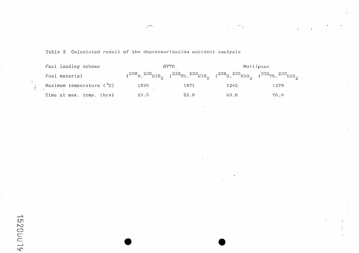
multipass scheme as rve expected. The maximum tezperetures
attained for each loading scheme and fuel cycle are summarized in
Table 3.
At the beginning of the accident, the temperature peaks for
the OTTO scheme occurred in the upper part of the core. On the
other hand, the peaks for the infinite-velocity multipass scheme
occurred at the lower part of the core. Eoth peaks moved toward
12
15200013

. .
the center of the core with the passage of time.
The masimum temperature of the OTTO scheme esceeded 1800°C
in 23.3 hours for uranium, and 22 hours for thorium cycles
respectively. The maximum temperatures of the infinite-velocity
multipass scheme were much lower than the 1600°C, further, their
temperature transients Kere n?lch slower. The differences in the
mesin:um peak temperatures bei~~=,~ ---1~ the t',i'o schemes exceeded 3OO'C;
considerably large from the reactor design point of view.
Clearly', the distributions of the fission product as well as the
decay heat production for the txo fuel loading schemes, can
explain the above results. The distributions of the fission
product and actinide for the infinite-velocitymultipass scheme
do not produce any peak, so the heat production density is
distributed more uniformly throughout the core.
However, in the usual multipass fuel loading scheme, the
fuel ball velocity is not infinite, and if velocity is very slow
the fission products' distribution becomes similar to the
distribution for'the OTTO fuel loading scheme: the peaks of the
distribution will then shift to the upper part of the core.
Slight differences in the maximum temperatures xere found
betxeen uranium and tho,l -lum fuel cycles. They were attributed to
the different radial power profile in the equilibrium condition
rvhich determined the decay heat productions.
In conclusion, the multipass fuel loading scheme is
relatively safer than the OTTO scheme for the depressurization
13
1?200014

accident, thouph the OTTO scheme aims to obtain the higher gas
outlet temperature with lower maximum fuel temperature at
operation condition. By use of the infinite-velocity multipass
loading scheme, a reactor can avoid the 1600°C by a safety
margin of about 300°C.

ACKXO\CLEDG?IEXT
The authors are very grateful to Dr. >I. Aritomi of Tokyo
Institute of Technology and Dr. T. Watanabe of Kawasaki Heavy
Industries, Ltd., for their edvice in performing the thermal
analyses.
REFEREXCES
(1) REL‘TLER, H.. LO:S\'E,PT, G. H.: Sucl. TeChnOl., 52, 2?(1933).
(2) SExI>iOTO, H., ei al.: J. of .\‘ucl. Sci. Technol., 24,
0 755(1S87).
(3) TEUCSERT, E., es al.: Jul-1649, (lOSO)
(4) BIRD, R.
Sons, 196
(3) IH.1R.4, IJ,.
(
B., et al.: "Ti-znspori Phenomena", John Kilev &
1960).
et al.: JAERI-?! 9715(1981)
15200016

.-.
Thermal ~owc,' (M\VI;II)
Core di.amcter (ITI)
Core height (III)
Mean power dcns,lLl~y (W/cc)
Multiplica1:j.o~~ ,Y:~cI:or
Fuel. lcmdlng SCII(!III(!
i;‘u c I. mate IT I ill
Enrichment (X)
Moderation R~~I;.i~o
Burnup (M\Vl3/tolr IIM)
Conversion ralA.0

concl~i.I::i,o~~
Ifelium tcmpcr;~I:urc: ( "C)
System pressure (atm)
Fuel load:l,nr: ~sc:l~cmc?
Fuel materid
Helium mass %‘:l.ow (kg/s)
Pressure ~11~01~ (i,tl.m)
Max. helj.um 1:omp. ( "C)
Max. Pucl surl'. I:c!mp. ("C)
. .

. . . .
1 r
O-
2 113 -
207 -
iO58-
1126-
-II69 -
i263-
(cm)
25 150 260 5 1 I
1 Reflector
Fig. 1 Reactor Configuration
(cm)

* . .
15
10
5.0
0.0
15
10
5.0
0.0
l
‘1 .‘Z.’
0
15200021

: .: .. : .‘.’ :Y:.:.=::s..
-. ..~.

0.30
T 0.25
3 0.20
z 5 0.15
2 0 g 0.10
0.30
z 0.25
g 0.20
z E 0.15 3 E E 0.10
2 2! 0.05
0
r-r ,
I I I I
T =l.h,
T =1Oh
. a,. ,
.
0 200 400 600 800 1000
DISTANCE FROM TOP OF THE CORE (cm)
iiz, 7 :-:d&i produciion aicer reactor s’hurdosa for OTTO ihoricm fuel c?cle 1520002~

IO O F-- ~~-t~~~-rrm~n-rrrrl~~~-nn”n’t-~~-r-r-l-i-l-r~~~-r I I I I I:
-
0' 10 2 IO3 IO 4. IO5 2
m (0 TfM,E AI?TEIR Sf-IUTDOWN (s)
IO 6 lOi
. - ,
.
0 c C’ w u
Fig. 13 lIeat production after reactor shutdoxn for inflnite-
velocity multipass uranium and thorium fuel cycles

2000
800
so0
400
1200
1000
800
600
400
r
I ! / 1 7’
I 4
DISTANCE FROM TOP OF THE CORE (cm)

1400
1200
t-
I I I I
T=63h (max)
i
DISTANCE FROM TOP OF TI-IE CORE (cm)
i 000
800
600
400
DISTANCE FROM TOP OF THE CORE (cm)
max
.--_
\
\


