
GENERATION OF HOMOGENEOUS GLOW DISCHARGE USING A
COMBINATION OF FINE WIRE MESH AND PERFORATED ALUMINIUM
ELECTRODE
NORAIN BINTI SAHARI
A project report submitted in partial fulfilment of the
requirements for the award of the degree of
Master of Engineering (Electrical-Power)
Faculty of Electrical Engineering
Universiti Teknologi Malaysia
JANUARY 2013

v
ABSTRACT
Nowadays, a gas discharge plasma applications has rapidly extended due to
the greatest chemical freedom offered by the non-equilibrium aspects of the plasma.
Among the applications of gas discharge plasma are surface treatment, air pollution
control, lasers, lighting, plasma displays, ozone generation and biomedical
applications. The most commonly used in plasma industry is the glow discharge
plasma. It is known to be generated under high vacuum condition. At low pressure
glow discharge plasma, the producing of surfaces and thin films are more effectives
and good quality. But, this technique gives disadvantages due to the large cost to
maintain at low pressure condition. However, there were many researches that have
been done to produce glow discharge at atmospheric pressure. This glow discharge
can be stabilize at atmospheric pressure if three simple requirements are fulfilled: (i)
use of source frequency of over 1 kHz, (ii) insertion of a dielectric plates between the
two metal electrodes, (iii) use of helium dilution gas. Used of helium gas is
impractical due to its high cost. In order to generate glow discharge at atmospheric
pressure in any gases, it was found that fine wire mesh and perforated aluminium can
maintain a stable glow discharges. This thesis focus on the production of
homogeneous glow discharge by using a combination of fine wire mesh and
perforated aluminium as electrodes. A study was also made to determine the effect of
a frequency and gap spacing on the stability of glow discharge.

vi
ABSTRAK
Pada masa kini, penggunaan penyahcasan gas plasma telah berkembang pesat
disebabkan aspek bebas kimia yang terdapat pada plasma tidak-seimbang ini. Antara
penggunaan penyahcasan gas plasma adalah rawatan permukaan, kawalan
pencemaran udara, lazer, pencahayaan, tatapan plasma, penghasilan ozon dan
penggunaan perubatan. Kebanyakan plasma yang digunakan dalam industri plasma
adalah penyahcasan plasma pijar. Ia dikenali untuk dihasilkan dibawah keadaan
vakum yang tinggi. Pada tekanan yang rendah, penghasilan permukaan dan filem
nipis adalah lebih efektif dan mendapat kualiti yang bagus. Tetapi, teknik ini tidak
memberi faedah kerana ia memerlukan kos yang tinggi untuk kekal pada keadaan
tekanan yang rendah. Walaubagaimanapun, banyak kajian telah dijalankan untuk
menghasilkan plasma gas ini pada tekanan atmosfera. Penyahcasan gas ini boleh
kekal dalam keadaan stabil sekiranya tiga syarat-syarat ini dipenuhi: (i) penggunaan
sumber frekuensi melebihi 1 kHz, (ii) penggunaan lapisan dielectric diantara
elektrod, (iii) menggunakan gas helium. Penggunaan gas helium tidak praktikal
kerana kosnya yang tinggi. Untuk menghasilkan penyahcasan gas ini pada tekanan
atmosfera dalam apa jua gas, ia telah dijumpai bahawa penggunaan wayar ‘mesh’
and aluminium yang berlubang boleh mengekalkan kestabilan penyahcasan gas ini.
Tesis ini fokus kepada penghasilan penyahcasan gas yang seragam menggunakan
gabungan wayar ‘mesh’ dan aluminium yang berlubang sebagai elektrod. Kajian juga
dibuat utnuk menentukan kesan frekuensi dan jarak elektrod pada kestabilan
penyahcasan gas ini.

vii
TABLE OF CONTENT
CHAPTER TITLE PAGE
DECLARATION i
DEDICATION iii
ACKNOWLEDGEMENT iv
ABSTRACT v
ABSTRAK vi
TABLE OF CONTENTS vii
LIST OF TABLES xi
LIST OF FIGURES xii
LIST OF ABBREVIATIONS xv
LIST OF SYMBOLS xvi
LIST OF APPENDICES xvii
1 INTRODUCTION
1.1 Research background 1
1.2 Problem Statement 3
1.3 Objectives 4
1.4 Scope of work 4
1.5 Methodology of project 5
1.6 Thesis outline 7
2 LITERATURE REVIEW
2.1 Introduction to glow discharge plasma 8
2.2 Electrical breakdown of gases 10
2.2.1 Townsend mechanism of electric breakdown

viii
of gases 10
2.3 Dielectric barrier discharge 12
2.3.1 Overview of the dielectric barrier discharge 12
2.3.2 Properties of the dielectric barrier discharge 14
2.3.3 Atmospheric pressure low discharge 15
2.4 Pulsed glow discharge 18
2.4.1 Pulsed and RF glow discharge in Helium
Atmosphere 19
2.5 Effect of Principal parameters on glow discharge
Generation 20
2.5.1 Gas dilution 21
2.5.1.1 Helium gas 21
2.5.1.2 Neon gas 23
2.5.1.3 Nitrogen gas 24
2.5.2 Dielectric barrier 25
2.5.3 Arrangement of discharge electrode 26
2.5.3.1 Multipoint-to-plane configuration 27
2.5.3.2 Wire mesh as an electrode 28
2.5.3.3 Perforated Aluminium as electrodes 29
2.5.4 Frequency applied 31
2.6 Application of glow discharge 32
2.6.1 Surface modification 32
2.6.2 Lamps 33
2.6.3 Plasma displays 34
2.6.4 Ozone generation 36
2.6.5 Increasing the surface energy of films and fabrics 37

ix
3 EXPERIMENTAL METHODS AND APPARATUS
3.1 High frequency power supply 38
3.1.1 Pulse generator 39
3.1.2 Components of pulse generator 40
3.2 Operation of pulse generator 42
3.2.1 Software implementation of pulse generator 43
3.2.2 Hardware implementation of pulse generator 44
3.2.3 Ignition coil 45
3.3 Operation Principles of Ignition coil 47
3.4 Hardware implementation of ignition coil 48
3.5 Glow discharge chamber design 48
3.5.1 Material selection of glow discharge chamber 48
4 EXPERIMENTAL RESULTS AND ANALYSIS
4.1 Experimental set-up 50
4.2 Results and Analysis of high frequency power supply 51
4.3 Generation of glow discharge 53
4.3.1 Characterictics of applied voltage and discharge
Current 54
4.3.2 Case I: Influence of frequency 55
4.3.2.1 Configuration I 55
4.3.2.2 Configuration II 56
4.3.3 Case II: Influence of gap spacing 57
4.3.3.1 Configuration I 58
4.3.3.2 Configuration II 59
4.4 Discussion 60
5 CONCLUSION AND FUTURE DEVELOPMENT
5.1 Conclusion 62
5.2 Future development 63

x
5.2.1 Uniformity of glow discharge system 63
5.2.2 Efficiency of glow discharge plasma system 64
REFERENCES 65
APPENDICES A-C 69-89

xi
LIST OF TABLES
TABLE NO. TITLE PAGE
2.1 Numerical parameters A and B for calculation of
Townsend coefficient 12
3.1 Timing chart values of C1 and C2 for the time machine 40
3.2 List of component for pulse generator 40

xii
LIST OF FIGURES
FIGURE NO. TITLE PAGE
1.1 Flow chart of the project 6
2.1 Schematic overview of the basic plasma processes in
a glow discharge 9
2.2 Illustration of the Townsend breakdown mechanism 11
2.3 Common dielectric-barrier discharge configuration 13
2.4 The storage phosphor image of filaments in the
dielectric-barrier discharge gap in air 14
2.5 Transition from a glow discharge to an arc discharge 16
2.6 A schematic representation of the apparatus 17
2.7 Diffused discharge in between the gap 19
2.8 V-I waveform 19
2.9 Several emissions spectral lines for various applied
potential using pulse and sinusoidal supply 20
2.10 Schematic diagram for the measurement Lissajous
figure of glow discharge in Helium 22
2.11 Glow discharge at 1.01 kV peak-to-peak and 11.8 kHz
frequency at 2.5mm gap distance under atmospheric
pressure 22
2.12 Pseudoglow discharge at 2.39 kV peak-to-peak and
11.8 kHz frequency at 2.5mm gap distance under
atmospheric pressure 23
2.13 Filamentary discharge at 20.09 kV peak-to-peak and
11.8 kHz frequency at 2.5mm gap distance under
xiii
atmospheric pressure 23
2.14 Experimental set-up 24
2.15 Typical waveform of the first breakdown and
stable diffuse 24
2.16 Schematic diagram for the experimental system 25
2.17 Schematic diagram of the experimental system 27
2.18 Photograph of corona discharge, glow discharge
and spark discharge 27
2.19 Current discharge and Lissajous Figure of SED
in pure Argon without wire mesh 28
2.20 Current discharge and Lissajous Figure of SED
in pure Nitrogen with wire mesh 28
2.21 Experimental set-up 29
2.22 Voltage and discharge current waveform for
steel wire mesh 30
2.23 Voltage and discharge current waveform for
perforated aluminium 30
2.24 Different steps in making an IC 33
2.25 Schematic diagram of the working principal
of a fluorescent lamp 34
2.26 Schematic representation of a coplanar-electrode
a.c plasma displays panel 35
2.27 Schematic representation of a plasma-activated
liquid crystal 36
2.28 Scanning electron micrographs of polypropylene
fibers 37
3.1 Elements of the high frequency power supply 38
3.2 Schematic diagram of the time machine 39
3.3 The operation of pulse generator 43
3.4 Schematic diagram of pulse generator in Proteus
Simulation 44

xiv
3.5 The hardware designed for pulse generator 45
3.6 Output waveform of pulse generator on
Oscilloscope 45
3.7 Ignition coil with three terminals 46
4.1 Complete experimental set-up for the generation
of glow discharge 50
4.2 Output waveform of pulse generator after connected
to ignition coil 51
4.3 Graph of output high voltage versus frequency of
power supply 52
4.4 Physical structure of perforated aluminium and
fine wire mesh 53
4.5 First configuration with the arrangement of two
Materials 54
4.6 Second configuration of electrode 54
4.7 Circuit to record discharge current waveform 55
4.8 Voltage and discharge current wavefrom for first
configuration at 1mm gap distance 56
4.9 Voltage and discharge current waveform for second
configurations at 1mm gap distance 57
4.10 Voltage and discharge current waveform for first
configuration at various gap distances 59
4.11 Voltage and discharge current waveform for second
configuration at various gap distances 60
5.1 Schematic diagram of glow discharge reactor with
matching circuit 64

xv
LIST OF ABBREVIATIONS
Hz - Hertz
ICP - Inductive Coupled Plasma
RF - Radio Frequency
DC - Direct current
CO2 - Carbon dioxide
H2 - Hydrogen
N2 - Nitrogen
He - Helium
Ar - Argon
DBD - Dielectric Barrier Discharge
APGD - Atmospoheric Pressure Glow Discharge
SED - Silent electric discharge
Al2O2 - Alumina Ceramic
CRT - Cathode Ray Tube
PDP - Plasma display panel
PALC - Plasma adressed liquid crystal
LC - Liquid crystal
PP - Polypropylene

xvi
LIST OF SYMBOLS
E - Electric field
V - Voltage
d - distance
i0 - low initial current
μe - electron mobility
α - Townsend coefficient
λ - secondary emission coefficient
cm - centimetre
A - Ampere
kW - kilowatt
x - thickness of dielectric
p - power dissipated
f - frequency
CD - dielectric capacitance

xvii
LIST OF APPENDICES
APPENDIX NO. TITLE PAGE
A Datasheet of 555 Timer 69
B Datasheet of IRFZ44N 80
C Datasheet of Series Voltage Regulator 89

CHAPTER 1
INTRODUCTION
1.1 Research background
In recent years, a gas discharge plasma applications has rapidly extended due to the
great chemical freedom offered by the non-equilibrium aspects of the plasma. Gas discharge
plasma present considerable interest for a wide range of applications such as surface
treatment, air pollution control, lasers, lighting, plasma displays, ozone generation and
biomedical applications [1].
The most commonly used in plasma spechtrochemist is the glow discharge plasma.
Glow discharge plasmas are known to be generated under a so-called high vacuum condition.
The producing of surfaces and thin films are more effectives and relatively good quality
under low pressure glow discharge plasma technique. However, this technique gives
disadvantages in its production process since it is necessary to maintain at low pressure
condition and therefore, a large amount of cost is necessary to keep the system air-tight.
In general, the glow plasma is thought to be stable only in a low pressure discharge. This is
because the discharge concentrates on one point a pressure of about 100 Torr. When the
pressure is rising, the discharge shifts to sparks and arc at about atmospheric pressure and
thus, making it impossible to uniformly process an object [2]. But, glow discharge is possible
to stabilize at atmospheric pressure if three simple requirements are fulfilled: (i) use of source
frequency of over 1 kHz, (ii)

2
insertion of a dielectric plate (or plates) between the two metal electrodes, (iii) use of
helium dilution gas [3,4]. Used of helium as dilution gas is able to produce a stable
and homogeneous glow discharge at atmospheric pressure is due to its low
breakdown stress and thus, makes it easy to produce the small avalanches that are
required [5]. On the other hand, the use of helium as dilution gas is impractical due
to its high cost. It is increases in interesting of researchers to use other low-cost of
gases. In this field, a new technique of stabilizing the homogeneous glow discharge
at atmospheric pressure in any gases by a 50 Hz source is proposed [6]. This method
used a fine wire mesh as a discharge electrodes and it is found that fine mesh
electrodes can maintain a stable glow discharges in any type of gases. In [7], it has
been confirmed that wire mesh is very important in increasing the possibility of the
existence of glow discharge plasma at atmospheric pressure. They also suggested
that the mesh could influence the discharge by its electrical resistance which is
higher than metallic electrodes. Besides fine mesh wire, perforated aluminium sheet
electrode is introduced for comparison with the well-known fine stainless steel wire
mesh. From this work, it was found that perforated material electrode can produce a
homogeneous glow discharge as an alternative of the well established fine steel wire
mesh [8].
This thesis focuses on the production of homogeneous glow discharge by
using a combination of fine wire mesh and perforated aluminium as electrodes. A
study of the relevant literature has confirmed that uniform and stable glow discharge
also dependent on the material of electrodes used. Uniformly distribution of the
electric field strength throughout the electrode surface may be due to the shape and
size of the holes, as well as the material used. However, the reason why glow
discharge has different stability when different configuration of material used as
electrodes is not clear. For this reason, further study on the effect of material used as
electrodes is proposed in this project. Combination of these two materials as
electrodes is introduced instead of using these two materials as electrodes separately.
A study was also made to determine the effect of a frequency and pulse of the input
voltage on the stability of glow discharge.

3
1.1 Problem Statement
Nowadays, the use of plasma which is generated by discharge has widely
applications including surface treatment of semiconductor, formation of thin films,
ozone generation, biomedical applications etc. Glow discharge is well-known
generated under low-pressure condition but it is costly in order to maintain at low-
pressure state. Thus, many researchers have worked out to introduce techniques
which can generate glow discharge plasma under atmospheric pressure to replace the
conventional low pressure glow discharge method. In order to achieve a stability of
glow discharge at atmospheric pressure, it depends on the feed gas, the dielectric
barrier material, the discharge electrode structure, the pulsed supply frequency, the
gap spacing and the humidity of the gas.
Homogeneous glow discharges can be established at atmospheric pressure by
using special kinds of electrode material and configuration. In [6], it has shown that
with wire mesh as electrodes behind the dielectric barriers homogeneous discharge
can be obtained with any gas at atmospheric pressure. This result also has been
confirmed by [7], and it has also been found that fine mesh electrodes produce a
more stable glow than coarse mesh electrodes.
Furthermore, for comparison with well established fine wire mesh, perforated
aluminium electrode was introduced into reaction chamber [8]. It has been found that
perforated aluminium with small holes can generate a homogeneous glow discharge
compared to fine wire mesh electrode. Initially, perforated aluminium is expected to
produce higher electric field strength than fine wire mesh due to its sharp edges
holes. Higher electric field strength can cause ionization that will produce more
micro-discharges near the electrodes. It further, will give a discharge that fills up the
whole volume of the discharge chamber.
Nevertheless, simulation results on the observation of electric field strength
between these two materials showed that wire mesh configuration produced higher
electric field strength than perforated aluminium. This result proved that electric
field strength does not influence the stability of the glow discharge. Thus, it makes
4
the reason why the glow discharge produced by the configuration with perforated
aluminium has better stability than the wire mesh is unclear.
In this present study, production of glow discharge by using a combination of
fine wire mesh and perforated aluminium as electrodes will be investigated. In
addition, the effect of frequency and pulse supply on the stability of glow discharge
also will be studied.
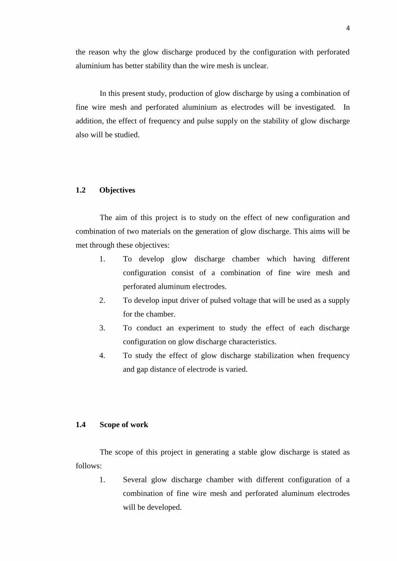
1.2 Objectives
The aim of this project is to study on the effect of new configuration and
combination of two materials on the generation of glow discharge. This aims will be
met through these objectives:
1. To develop glow discharge chamber which having different
configuration consist of a combination of fine wire mesh and
perforated aluminum electrodes.
2. To develop input driver of pulsed voltage that will be used as a supply
for the chamber.
3. To conduct an experiment to study the effect of each discharge
configuration on glow discharge characteristics.
4. To study the effect of glow discharge stabilization when frequency
and gap distance of electrode is varied.
1.4 Scope of work
The scope of this project in generating a stable glow discharge is stated as
follows:
1. Several glow discharge chamber with different configuration of a
combination of fine wire mesh and perforated aluminum electrodes
will be developed.

5
2. Input driver of pulsed voltage will be developed.
3. An experimental work will be conducted to study the effect of each
discharge configuration on glow discharge characteristics.
4. The glow discharge generated will then be detected and then will be
analyzed in order to identify the homogeneity of the discharge.
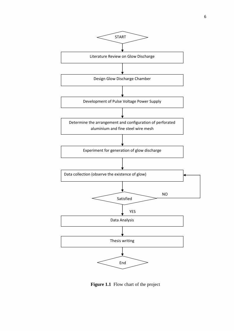
1.5 Methodology of Project
This project is done in sequence in order to ensure that the project will be
done in a specific time. The flow of this project is as shown below:
6
Figure 1.1 Flow chart of the project
START
Literature Review on Glow Discharge
Development of Pulse Voltage Power Supply
Determine the arrangement and configuration of perforated
aluminium and fine steel wire mesh
Design Glow Discharge Chamber
Experiment for generation of glow discharge
Data collection (observe the existence of glow)
Satisfied
Data Analysis
Thesis writing
End
NO
YES

7
1.6 Thesis Outline
This thesis is divided into five chapters. Each chapter is briefly described as
below:
Chapter 1 is the introduction of this project including brief description on
background of study, problem statements, objectives, scopes of work and
methodology of this project.
In chapter 2, the literature review on glow discharge is being discussed.
Several sources of information consist of research papers, journal and reference
books that help the implementation of this project are further elaborated.
In chapter 3, the methodologies and apparatus of the project are being
discussed. It consists of two main parts, the high frequency power supply and the
glow discharge chamber.
The results and analysis of the project are discussed in chapter 4. Two types
of results are covered in this chapter which are influences of frequency and
influences of gap spacing.
Chapter 5 is the conclusion and future development of this project. Some
suggestions are provided in this chapter for further improvement of this project.

8
CHAPTER 2
LITERATURE REVIEW
2.1 Introduction to glow discharge plasma
Glow discharge is a process occurs when an adequately high potential
difference is applied between two electrodes. The gas between these two electrodes
will break down into positive ions and electrons. This process of breakdown giving
rise to a gas discharge. Electrons emitted from the cathode are not able to maintain
the discharge without applying a potential difference. In the presence of voltage
difference, electrons near to the cathode are accelerated by the electric field and have
a collision with the gas atoms. The collision between electrons and atoms will give
rise to an inelastic collisions and leading to excitation and ionization process. The
characteristics name of the ‘glow’ discharge are responsible by the excitation
collisions that normally followed by de-excitation which can cause emission of
radiation. The process of ionization can create new electrons and ions. The latter can
cause secondary electrons emission at the cathode and give rise to new ionization
collisions. Therefore, the glow discharge in the plasma is self-sustaining plasma due
to the process of electrons emission at the cathode and ionization in the plasma.

9
Figure 2.1 Schematic overview of the basic plasma processes in a glow discharge
Basically, plasma-chemical systems are divided into two major categories
which are thermal and non-thermal. It is characterized by their specific advantages
and disadvantages. Thermal plasma is associated with thermal ionization, Joule
heating and able to deliver high power up to 50 Megawatts per unit at high operating
pressures. Thermal plasma usually an arcs or Radio Frequency Inductively Coupled
Plasma (ICP) discharges. However, thermal plasma sources have limit energy
efficiency and applications due to the low excitation selectivity, very high gas
temperature, electrode problem result and serious quenching requirements. At low
pressure glow, RF and microwave discharge it is called non-thermal plasma. Non
thermal plasma presents high selectivity and energy efficiency of plasma chemical
reactions. It has advantages than does thermal plasma where it is able to operate
effectively without any special quenching and at low temperature. Due to its
advantages, non-thermal plasma atmospheric pressure has been studied for variety
industrial applications such as removal of volatile organic compounds, control the
car exhaust emission, a pollution control and treatment of surface polymer. Non-
thermal plasma also widely used to generate ozone for water purification.
Non-thermal plasma may be generated by using electrical discharge or beams
of electrons. They produce plasma when electrical energy goes into the production of
energetic electrons besides of heating the entire as stream. These energetic electrons
create excited free radicals, ion and additional electrons through dissociation,
excitation and ionization of gas molecules. All these excited species reduce the
pollutant molecules in the applications of pollutions control. On the other hand, in
thermal process such as plasma-torches or furnaces and some chemical techniques

10
require heating the whole gas stream for the purpose to destroy the pollutants. Non-
thermal plasma has widely used in industry also due to the low temperature plasma
technologies and have relatively low maintenance requirements resulting in relatively
low energy costs.
2.2 Electrical Breakdown of Gases
2.2.1 Townsend mechanism of electric breakdown of gases
The electrical breakdown is a process of formation conductive gas which
occurs when electric field exceeds some critical value. Different kind of plasma will
be generated as a result of the breakdown different. The breakdown mechanism starts
with the electron avalanche which is multiplication of some primary electrons in
cascade ionization [14].
This mechanism can be described by considered the simplest breakdown in a
plane gap of spacing d between electrodes. It connected to a DC power supply which
provides the homogeneous electric field E = V/d. By providing the very low initial
current i0, some primary of electrons are formed near the cathode. Each primary
electrons that formed at the cathode drift to anode to ionize the gas and therefore
generates an avalanche. This is the procedure of emission of secondary electrons.
Due to the multiplication of electrons proceeds along with their drift from cathode to
anode, the avalanche develops both in time and in space (see figure 2.2). The
ionization avalanche is by the Townsend ionization coefficient, α and not by the
ionization rate coefficient. It is shows the electron production in per unit length or the
multiplication of electrons. The Townsend ionization coefficient is related to electron
drift velocity vd and ionization rate coefficient ki(E/n0) :
(2.1)

11
Where,
vi = ionization frequency with respect to one electron
μe = electron mobility
The breakdown starts at room temperature and the mobility of electron is inversely
proportional to pressure.
Figure 2.2 Illustration of the Townsend breakdown mechanism
From the definition of the Townsend coefficient α, each one primary electron
created near the cathode produce exp(αd) – 1 positive ions in the gap as shown in
figure 2.2. In electronegative gases, the attachment processes are most important and
will be discussed below.
All the positive ions created in the gap per one electron are moving back to
the cathode and the γ (exp(αd) – 1) electrons are knocked out from the cathode in the
process of secondary electron emission. γ is the secondary emission coefficient also
called third Townsend coefficient and depends on cathode material, state of surface,
type of gas and reduced electric field. It is defined as probability of a secondary
electron generation on the cathode by an impact. The usual value of γ is 0.01-0.1 in
electric discharge. It is depends on effects of photons, meta-stable atoms and
molecules on the secondary electron emission.

12
Table 2.1 : Numerical parameters A and B for calculation of Townsend coefficient
Gas A, 1/cm Torr B, V/cm Torr
Air 15 365
CO2 20 466
H2 5 130
N2 10 310
He 3 34
Ar 12 180
When the electric field and Townsend α coefficient becomes high enough,
transition to self-sustained current takes place. This is actually the breakdown
mechanism. Therefore, the simplest breakdown condition in the gap can be shows as:
γ[exp(αd) – 1] = 1, αd = ln(1/γ +1) (2.2)
2.3 Dielectric Barrier Discharge
2.3.1 Overview of the dielectric barrier discharge
Dielectric barrier discharge (DBD) is a discharge system formation when
dielectric barrier is placed inside the discharge gap. It then will stop the electric
current and avoid spark formation which is from streamer to spark transition. This
discharge system usually operates at frequencies between 0.05 and 500 kHz. In other
words, DBD also called silent discharges due to the nonexistence of spark which are
accompanied by generation of local shock waves and noise.

13
Dielectric barrier discharges have largely applications in industry because
they operate under non-equilibrium conditions at atmospheric pressure and high
power levels without using complicated pulse power supplies. This discharge is
widely used in generation of ozone, CO2 lasers and as a UV-source in lamps. DBD
also applied in air and it is normally used in the web conversion industry where it is
known as corona discharge treatment. Corona discharge treatment is used to treat
polymer outside in order to support printability, wettability and adhesion [15]. DBD
application also used in pollution control btu the largest application of DBD is on the
production of plasma display panels for large-area flat television screens.
Kogelschatzs, Eliasson and their group [16] has gives important contributions
in fundamental understanding and industrial applications of DBD. However, this
DBD actually has a long history. Essential steps in understanding the physical
structure and nature of the DBD were made by Klemene in 1937 [17].
Figure 2.3 Common dielectric-barrier discharge configuration [22]

14
2.3.2 Properties of the dielectric barrier discharges
The dielectric barrier discharge gap normally contains one or more dielectric
layers. It is located in the current path between metal electrodes. As illustrated in
figure 2.3, there are two specific DBD configurations which are planar and
cylindrical form. Typical gap distance between these two electrodes varies from 0.1
mm to several centimetres. The dielectric barrier can be made from mylar, glass,
ceramics, quartz or other materials that has low dielectric loss and high breakdown
strength.
Figure 2.4 The storage phosphor image of filaments in the dielectric barrier
discharge gap in air
Usually, dielectric barrier discharges are not evenly distributed and contain of
plentiful microdischarges in the discharge gap as can be seen in figure 2.4.
It is important to distinguish and clarify the terms streamer and
microdischarge. An initial electron starting from cathode or dielectric that covers the
cathode and produces secondary electrons by direct ionization and electron
avalanche is developed. If the electrons avalanche is big enough than cathode, direct
streamer is initiated. Streamer forms a conducting channel of weakly ionized plasma
and bridges the gap in few nanoseconds. Inside the plasma channel, the intensive
electron current will flow until local electric field is collapse. Electric field collapse
is due to the charges accumulated on dielectric surface and ionic space charge. The
ions are too slow to leave the gap for the duration of this current peak. Group of local

15
processes in the discharge gap are developed and initiated by avalanche until the
termination of electron current. This is usually called microdischarge. There is no
more electron-ion plasma in the main part of micro-discharge after electron current
termination. However, this region is separated from the rest of the volume due to
high level of vibrational and electronic excitation in channel volume. This process is
called microdischarge remnant. Microdischarge remnant will produce new
microdischarge in the same spot as the polarity of the applied voltage changes. This
phenomenon give cause the possibility to see single filaments in DBD.
2.3.3 Atmospheric pressure glow discharge
Dielectric barrier discharge (DBD) can display two major discharge mode
which are filamentary mode and homogeneous or glow discharge mode. The
filamentary mode has been discussed previously and widely utilized in industrial
applications. Nevertheless, for deposition of thin films or treatment of surfaces, the
glow discharge mode has clearly advantages over the filamentary one.
Glow discharge can be occurred at either atmospheric pressure or low
pressure. Since the last century, many research projects on glow discharge at low
pressure were developed and it is well established. It is widely used in many
applications such as surface treatment, light sources and thin film coating. Yet, it is
costly in order to maintain at low-pressure condition. Due to this limitation, many
researches had been implemented on stabilization of glow plasma at atmospheric
pressure. Several researchers [3,4] claimed that glow plasma is possible to stabilize
at atmospheric pressure if three simple requirements are fulfilled: (i) source of
frequency is over 1 kHz, (ii) dielectric plate is inserted between the two metal
electrodes, (iii) helium is used as a dilution gas.
Typically, in APGDs, dielectric is covered at least one of the electrodes and
the discharge operates at alternating voltage. In addition, the stability of the glow
discharge is also determined by the type of gas discharge used. For example, helium
gas can produce a stable homogeneous glow discharge, but nitrogen, oxygen and

16
argon can easily cause the transition into a filamentary glow discharge. However,
since the helium gas is costly, it is still possible to let other gases operate in a
homogeneous glow discharge by changing the electrode configuration [3,6].
A new technique to produce a stable homogeneous glow discharge at
atmospheric pressure by a 50 Hz source in any gas is proposed [6]. This paper also
consists a method of distinguishing between a glow discharge and a filamentary
silent electric discharge. This work used atmospheric air, nitrogen, argon and oxygen
as dilution gas which is easily produce an silent electric discharge (SED).
Figure 2.5 Transition from a glow discharge to an arc discharge
The discharge at atmospheric pressure starts from the Townsend discharge, as
shown in figure 2.5. It then changes to a glow discharge (first glow), filamentary
glow (second glow discharge) and finally to an arc discharge. The transition time
from Townsend to arc discharge is depends on the gas pressure, the kind of gas,
discharge gap length and state of the over-voltage. The discharges will show the
homogeneous normal glow if the discharge stops before arriving at the second glow.
In order to bring a stable glow discharge in pure argon, nitrogen, oxygen and air at
atmospheric pressure, metal wire mesh which has a specified wire radius is used as
electrodes. The monitoring method of distinguishing between stable and filamentary
glow discharge has to use two figures which are the Lissajous figure of voltage-
charges and the single pulse current shape. This new method is introduced because
the previous work [10] has distinguished these two discharges by appearance of the
cathode spots and by the increase in current. However, the current value changes
continuously.

17
In [4], they succeeded in avoiding a conversion to an arc discharge at
atmospheric pressure by using two electrode styles. Firstly, an insulating plate was
set on the lower electrode plate or on the bottom of the upper electrode as shown in
figure 2.6(a). Other configuration is shows in figure 2.6(b) which is by using a brush-
style electrode which consists of sharp pointed fine tungsten wires. These two
electrode styles result in large differences in the samples. APGD plasma with a
brush-style electrode could not treat electrically conductive substances such as metal
because the discharge would change to an arc style. Therefore, a metal sample has to
be treated by a plate-style electrode.
(a) (b)
Figure 2.6 (a) A schematic representation of the apparatus: 1. Upper electrode; 2.
Lower electrode; 3 and 4. Glass plates; 5. Pyrex tube; 6. Pyrex bell-jar; 7. O-ring (b)
The brush style electrode.
Instead of using well-established fine wire mesh, perforated material as
electrodes also has been introduced [8]. Perforated aluminium has been selected in
this investigation is due to its arrangement of small holes with sharp edges. This
special arrangement is expected to produce higher local electric field strength than
fine wire mesh where higher electric field in the gap may be sufficient to cause
ionization of the gas. Ionization in gas will create more micro-discharge near the
electrodes which will provide a discharge that fills the whole volume of the discharge
chamber.
Nevertheless, simulation results on the observation of electric field strength
between these two materials showed that wire mesh configuration produced higher
electric field strength than perforated aluminium. This result proved that electric field

18
strength does not influence the stability of the glow discharge. Thus, it makes the
reason why the glow discharge produced by the arrangement with perforated
aluminium has better stability than the wire mesh is unclear. Uniformly and stable
glow discharge on the dielectric surface may be due to the shape, size of the holes
and material used which helps to distribute homogeneously the electric field strength
throughout the electric surface [8]. This author also claimed that a better stability of
the glow discharge can be achieved with smaller diameter perforated holes of
different shape. This claimed is based on the preliminary experimental results which
indicated that with small diameter holes of perforated aluminium, the glow discharge
generated is more stable than with bigger holes of perforated aluminium.
2.4 Pulsed glow discharges
The glow discharge voltage can also be applied in the form of discrete pulses
normally with lengths of milli-to microseconds. Pulsed glow discharge has better
efficiency and better sensitivities for analytical spectrochemistry. It is because a
pulsed discharge can operate at much higher peak current and peak voltages for the
same average power, hence can give higher instantaneous sputtering, ionization and
excitation. Recently, more investigations have focused mainly on microseconds
discharges because it is expected that even higher peak voltages and currents are
applied, better sensitivities can be obtained [9]. Typical analytical microsecond
pulsed conditions has a voltage of 2 kV, which is applied during a pulse of 10 μs,
with a pulse repetition frequency of 200 Hz. It giving rise to a peak currents of 1 A
and powers of 2 kW approximately [9]. This authors claimed that the typical duty
cycle is very short due to the ratio of ‘pulse-on’ period compared to ‘pulse-off’
period is very small. The average electrical power is relatively low, so that the
sample will not excessively be heated.
The glow discharge in air at atmospheric pressure simply transition into spark
discharges that significantly heat the gas. Thus, in order to control efficiently the
glow-to-spark transition, nanosecond repetitively pulse discharge is used [12]. In
these discharges, the application of high voltage nanosecond duration pulses generate

19
a strong electric field that accelerates electrons to the high energies required for
efficient ionization, whereas the short pulse duration prevent spark formation.
2.4.1 Pulsed and RF glow discharge in Helium atmosphere
The optical and electrical characterization of sinusoidal and pulse glow-
discharge plasma in helium can be obtained. In previous work [19] the dependence
of different discharge parameters on the operating conditions has been illustrated.
Figure 2.7 illustrates the average image of discharge that was taken by using digital
camera. The image shows that the glow discharge covers the whole surface of the
electrodes. Figure 2.8 (a) and (b) show the total current mark out together with the
applied voltage using pulse and sinusoidal waveform respectively. Both the image
and total current confirm the glow type discharge in helium dielectric barrier
discharge. As shown in figure 2.8, it gives an explanation that even for same applied
potential more current have been observed in case of pulse waveform.
Figure 2.7 Diffused discharge in between the gap
(a) (b)
Figure 2.8 V-I waveform (a) pulse at 600mbar and 30 kHz (b) sine wave at 600mbar
and 30 kHz

20
Figure 2.9 (a) and (b) demonstrate the several emissions spectral lines for
various applied potential using pulse and sinusoidal supply respectively.
(a) (b)
(a) (b)
Figure 2.9 (a) intensities of different emission lines vs. Pressure using pulse
waveform (b) intensities variation of emission lines vs. Applied potential sinusoidal
waveform
The pulse excitation is found to be more stable and more efficient compared
to sinusoidal waveform for the same operating conditions by the confirmation of
kinetic simulation. Electron concentration is continuously increasing with the
increased as pressure for the same simulation time. It is shows that pulse excitation
gives more power so the more current and highly intense spectral lines of helium
discharge for the same repetition rate as for the sinusoidal waveform.
2.5 Effect of Principal Parameters on Glow Discharge Generation
Generally, in order to achieve high stabilization on the production of glow
discharge, it must be generated under low pressure of less than a few mbar [6]. Even
so, it is costly to maintain the pressure at low condition. As pressure increase to
atmospheric condition, the glow discharge is usually unstable and started to change
to a filamentary discharge [13]. At atmospheric condition, glow discharge can be
stable dependent on the specific gas dilution, the composition of the dielectric

21
barrier, the arrangement of the discharge electrode, the applied frequency, the gap
spacing between electrodes and the gas humidity [3,4,6,8].
2.5.1 Gas Dilution
Normally, glow discharge is only visible at the voltage where the ionization
point is occurred. There is no glow under ionization voltage or breakdown voltage.
The occurrence of small avalanches under low field is necessary to obtain a glow
discharge at atmospheric pressure. Thus, in order to produce glow discharge easily, it
is related to low breakdown voltage of dilution gas. Helium is well known as a gas
that has the ability to produce a stable glow discharge at atmospheric pressure. It has
very low breakdown voltage at 1 atm which is only about 300 V/mm, some 10 times
lower than air. In contrast, helium is not practical in used due to its high cost even
though it is good for generating a homogeneous glow discharge at atmospheric
pressure. In [13], other low cost gases have been found to replace the helium dilution
gas. They used pure argon and pure nitrogen instead of helium due to conveniently
low in cost. However, these two gases cannot stabilize the glow discharge and they
will produce a silent electric discharge in form of filamentary.
2.5.1.1 Helium Gas
In [20] the experimental work has been done to investigate the Lissajous
figure of glow and pseudoglow homogeneous glow discharge in helium under an
11.8 kHz voltage at atmospheric pressure. The experimental set-up for the
measurement of the discharge current and Lissajous figure for this work is shown in
figure 2.10:

22
Figure 2.10 Schematic diagram for the measurement Lissajous figure of glow
discharge in Helium
The homogeneous glow discharge was generated under the appled voltage
with peak-to-peak amplitude of 1.01 kV. It is characterized by one discharge current
pulse per one half cycle of the applied voltage as shown in figure 2.11 (a). From
figure 2.11 (b), the glow discharge also can be characterized by only one step on the
left-hand and right-hand sides of the Lissajous figure paralellogram.
(a) (b)
Figure 2.11 Glow discharge at 1.01 kV peak-to-peak and 11.8 kHz frequency at
2.5mm gap distance under atmospheric pressure. (a) Discharge current waveform, (b)
Lissajous Figure
As applied voltage is increases to 2.39 kV peak-to-peak, the current pulse in
discharge waveform is increases to 3 pulses per each half cycle of applied voltage as
shown in figure 2.12 (a). The Lissajous figure (figure 2.12 (b)) is characterized by
three steps on left and right hand side of parallelogram. This state is called as
pseudoglow discharge.

23
(a) (b)
Figure 2.12 Pseudoglow discharge at 2.39 kV peak-to-peak and 11.8 kHz frequency
at 2.5mm gap distance under atmospheric pressure. (a) Discharge current waveform,
(b) Lissajous Figure
Figure 2.13 (a) and (b) show the discharge current waveform and Lissajous
figure respectively when the applied voltage is increases to 20.09 kV under
frequency of 11.8 kHz. These figures show that the discharge is at filamentary mode
since there are too many pulses in current discharge waveform. For Lissajous figure,
it is regular parallelogram because many steps are too little to display.
(a) (b)
Figure 2.13 Filamentary discharge at 20.09 kV peak-to-peak and 11.8 kHz
frequency at 2.5mm gap distance under atmospheric pressure. (a) Discharge current
waveform, (b) Lissajous Figure
2.5.1.2 Neon Gas
A diffuse discharge in neon at atmospheric pressure was investigated in [21]
with electrical dimension and rapidly photography. It was found that with a gap
space from 0.5-6mm, an even diffuse discharge can be easily generated and it is

24
known as glow discharge. The experimental setup for this work is shown in figure
2.14.
Figure 2.14 Experimental set-up
From figure 2.15 (a), the first breakdown occur at 1000 V at gap spacing of
6mm. Small discharge current peak is place over the displacement current. Then, by
slowly increasing the applied voltage, the result shows a transition of the discharge
from the first breakdown to a stable discharge as shown in figure 2.15 (b).
(a) (b)
Figure 2.15 (a)Typical waveform of the first breakdown (b)Typical waveform of
stable diffuse
2.5.1.3Nitrogen Gas
In [22] a homogeneous dielectric barrier discharge in nitrogen at atmospheric
pressure was investigated. From this work, it was proved that by including of a
nitrogen as a gas flow, a stable homogeneous discharge only can be produced in a
gap not longer than 3mm spacing. The experimental set-up is shown in figure 2.16
where the electrodes were made of stainless steel plates and both electrodes were
covered by a quartz plate of thickness 1mm. A conducting glue called high purity
silver paint was used on the metal and dielectric interface in order to make a good
contact between these two materials.

65
REFERENCES
1. Bogaerts A, Neyts E, Gijbels R, Mullen J V D, “Gas discharge plasma and
their applications”, Spectrochimica Acta Part B 57, pp. 609-658 (2002)
2. Okazako S, Kogoma M, “Method for monitoring atmospheric pressure glow
discharge plasma using current pulse-count and/or Lissajous figure”, United
States Patent.(1996)
3. Kanazawa S, Kogoma M, Moriwaki T and Okazaki S, “Stable glow plasma at
atmospheric pressure”, J.Phys. D: Appl.Phys., Vol 21, pp. 838-840.(1988)
4. Yokoyama T, Kogoma M, Moriwaki T and Okazaki S, “The mechanism of
the stabilisation of glow plasma at atmospheric pressure”, J.Phys. D :
Appl.Phys., Vol. 23, pp. 1125-1128. (1990)
5. Raizer Y P, “ Gas Discharge Physics”, (Berlin, Springer) (1991)
6. Okazaki S, Kogoma M, Uehara M and Kimura Y, “Appearance of stable
glow discharge in air, argon, oxygen and nitrogen at atmospheric pressure
using a 50 Hz source”, J.Phys. D: Appl.Phys., Vol 26, pp. 889-892. (1993)
7. Trunec D, Brablec A and Buchta J, “Efficiency of ozone production in
atmospheric pressure glow and silent discharges”, Proc. of Int. Symp. On

66
High Pressure, Low Temperature Plasma Chemistry, Hakone VII, Greifwald,
Germany, pp. 313-317. (2000)
8. Buntat Z, Smith I R, Noor. A. M. Razali, “Generation of a Homogeneous
Glow Discharge: A Comparative Study between the Use of Fine Wire Mesh
and Perforated Alumunium Electrodes”, Applied Physics Research, Vol. 3,
No. 1, May 2011.
9. W.O Walden, W. Hang, B.W. Smith, J.D Winefordner, W.W. Harrison,
“Microsecond-pulse glow discharge atomic emission”, Fresenius J. Anal.
Chem. 355 (1996) 442-446
10. Kekez M M, Barrault M R and Crags J D, 1970, J. Phys. D: Appl. Phys. 3
1886.
11. Kogoma M and Okazaki S, “Raising of ozone formation efficiency in a
homogeneous glow discharge plasma at atmospheric pressure”, J.Phys. D :
Appl.Phys., Vol 27, pp. 1985-1987.(1994)
12. F. Tholin, D. L. Rusterholtz, D. A. Lacoste, D. Z. Pai, S. Celestin, J. Jarrige,
G. D. Stancu, A. Bourdon, C. O. Laux, “Images of Nanosecond Repetitively
Pulsed Glow Discharge between Two Point Electrodes in air at 300 K and at
Atmospheric Pressure”, IEEE Transaction on Plasma Science, Vol.39, No.11,
November 2011.
13. Tepper J and Lindmayer M, “Investigations on two different kinds of
homogeneous barrier discharges at atmospheric pressure”, Proc. of Int.
Symp. On High Pressure, Low Temperature Plasma Chemistry, Hakone VII,
Greifwald, Germany, pp. 38-43.(2000)

67
14. P.Zheng and U.Kortshagen, “Atmospheric Pressure Glow Discharge
Initiation From a Single Electron Avalanche”, IEEE Transaction on Plasma
Science, Vol 33, No 2, pp 318-319 (2005)
15. Hood J L Int. Conf. on Gas Discharges and their Applications, Edinburgh, 86
(1990)
16. Kogelschatz U, Eliasson B, Egli W, J. Physique IV, Vol. 7, Colloque C4,
October 1997, C4-47 to C4-66.
17. Klemenc A, Hinterberger H and Hofer H 1937 Z. Elektrochem. 43 261
18. J.Reece Roth, IEEE Fellow, Prospective Industrial Applications of the One
Atmosphere Uniform Glow Discharge Plasma
19. P. Gulati, U.N.Pal, N. Kumar, V Srivastava, R. Prakash and V. Vyas, “Pulsed
and RF glow discharge in Helium Atmosphere”, International Symposium on
Vacuum Science on Vacuum Science & Technology and its Application for
Accelerators (2012)
20. X. L. Wang, Y. P. Hao and L. Yang, “Lissajous Figure Characteristics of
High Frequency Homogeneous Dielectric Barrier Discharge in Helium at
Atmospheric Pressure”, International Conference on High Voltage
Engineering and Applications, November 9-13 (2008)
21. J. Ran, H. Luo and X. Wang, “ A dielectric barrier discharge in neon at
atmospheric pressure”, Journal of Physics D: Applied Physics, 5pp (2011)
22. H. Luo, Z. Liang, X. Wang, Z. Guan and L. Wang, 2010 “Homogeneous
dielectric barrier discharge in nitrogen at atmospheric pressure”, Journal of
Physics D: Applied Physics, March 2010

68
23. R. Vertriest, R. Morent, J. Dewulf, C. Leys and H. V. Langenhove, 2003
“ Multi-pin-to-plate atmospheric glow discharge for the removal of volatile
organic compounds in waste water”, Plasma Source science and technology,
June 2003


