Compressor Support: 866-869-3114
Illustration Part DescriptionNumber US660V US580V
1 Compressor B3800 T29S BBBBBBB2 Air Filter 2281000 49810003 Electric Motor M182711 M1827034 Safety Valve 1400110 SV252005 Pressure Switch PSMDR21130 PS30M6 Tank Gauge 1400111 14004317 Tank Drain FIB02DC FIB02DC8 Check Valve CV21 CV219 Discharge Tube DT026 DT00510 Belt Guard 833500D BG31184 Drive Belts BA56 BA61 Drive Pulley SAK5658 SAK56H
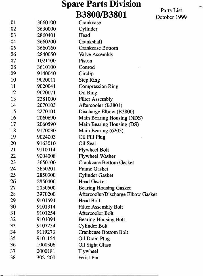
*Part Numbers Subject to Change Without Notice
0110
09
08
07
06
05
04
0302
Electric Compressors
US7580VB6000
FS002MM36H675SV25200PS10M
1400431FIB02DC
CV22DT023
BG31184BA67(2)
S2AK61H

Model #: _______________ Serial #: _______________(Record now for future reference.)
AIR COMPRESSOR
INSTALLATION
AND START-UP
MANUAL
Table of Contents
Page#
1. INTRODUCTION
2. OWNER'S OBLIGATIONS
3. INSTALLATION AND START UP
4. INSTALLATION AND START UP / GAS
5. TROUBLE-SHOOTING GUIDE / GAS
6. TROUBLE-SHOOTING GUIDE
7. PERIODIC MAINTENANCE
8. WARRANTY PROCEDURE
9. COMPRESSOR WIRING AND GENERALINSTALLATION DIAGRAM

CONGRATULATIONS! Your new compressor is designed and built by professionals for professionals. Be assured that your
compressor has passed extensive quality testing, so we are confident that you have received a
compressor that is ready to go to work for you.
REMEMBER ...
REMEMBER – all machinery does require some care and attention. Failure to attend to the periodic
checks listed below may result in damage or poor performance, and may void the warranty on your
compressor. Check compressor nameplate to be sure the unit is the model and size ordered. Do this
before uncrating. Check receiver nameplate to be sure the tank is adequate for pressure at which you
intend to operate.
Check motor nameplate to be sure motor is suitable for your electrical condition (Volts Phase-Hertz-
Amps). PLEASE NOTE: A full voltage starter is recommended on units larger than 3HP electric motor
unit. Starters are available mounted and wired as an option on most machines. Consult your local
electrical code/electrician.
Tank DrainValve
DischargeValve
SafetyValve
Motor
Pressure Switch
CheckValve
Inlet Filter
Oil Level SightGlass
TankPressureGauge
NOTE: This Diagram represents general compressor components and may differ from your compressor.
1
OWNER’S OBLIGATIONSINSTALLATION OF COMPRESSOR
The compressor must be located in a clean, dry, well ventilated area in order to provide an
adequate supply of clean, cool, dry, fresh air to the intake and to cool the unit.
The compressor flywheel must have a minimum clearance of 12" from any obstructions (walls,
cabinets, etc.) to insure proper cooling. Flywheel rotation is clockwise when facing the oil
sight glass.
The compressor must be installed so that the pump is level in order to allow for properlubrication.
Anchoring the compressor to the floor is NOT recommended. When this is necessary, the tank
legs MUST BE SHIMMED in order to avoid undue stress on the tank welds. Vibration isolator
pads are STRONGLY RECOMMENDED.
All electrical wiring and connections must be done by a qualified electrician and must be in
accordance with all national and local electrical codes.
MAINTENANCE OF COMPRESSOR
Refer to page 7 of this manual or maintenance decal on complete package for maintenance
instructions and service schedule.
Compressor oil level should be maintained at the halfway point on the sight glass. The oil should
be changed as required (at least every 3 months or 300 hours) and should be a 30 weight,
non-detergent, air compressor rated oil (40 weight for Single Stage Compressors).
For complete packages with gasoline engines, follow the engine manufacturers
recommendations for oil changes, oil types, and oil levels.
Proper belt tension should be maintained at all times. Belts should be checked regularly forwear.
Air intake filters, as well as the complete unit, should be cleaned frequently.
All nuts, bolts, capscrews, and fittings should be kept tight.
FAILURE TO COMPLY WITH THE ABOVE PROCEDURES MAY VOID YOURWARRANTY.
2

Gas Drive CompressorsStarting the Compressor
Electric start models:Make Sure There is Gas in the Gas Tank
Honda: Turn the gas lever to the “on” position. Turn the choke lever to the left.Turn key to the “on” position, then to the “start” position. Once theengine is running, turn the choke lever to the original “right hand”position.
Kohler: Turn the gas lever counterclockwise to the “on” position. Slide the "choke"lever to the choke position. Turn the key to the “run” position, then to the“start”position. Once the engine is running, slide the choke lever back tothe "run" position.
Intek: Turn the gas lever to the vertical “on” position. Slide the choke lever toto the “choke” position. Turn the key to start the compressor. Once theengine is running, slide the choke lever to the“run” position.
Vanguard: Turn the gas lever to the vertical “on” position. Slide the choke lever toto the “choke” position. Turn the key to the “on” position, then to the“start” position. Once the engine is running, slide the choke lever tothe“run” position Make no adjustment to the throttle control lever.
Recoil Start Models:Briggs: (Standard)Slide choke lever to the “choke” position. Slide throttle control
lever to the left. Pull starter grip to start engine, return slowly. Once theengine is running, slide the choke lever to the “run” position.
Honda: (5hp)Pull choke lever toward you. Pull starter grip to start engine, returngrip slowly. Once engine is running, push choke back to original position.(5.5hp)Turn the switch on the right side of the engine to the “on” position.Slide the choke lever(gray lever) to the left which is the “choke” position.Slide the gas lever (black lever) to the right which is the “on” position.Pull starter grip to start engine, return slowly. Once the engine is running,slide the choke lever back to the right.
Vanguard: Turn the gas lever to the vertical “on” position. Slide the choke lever to“choke” position. Flip on/off switch to the “on” position. Pull starter gripto start engine, return slowly. Once the engine is running, slide chokelever to the “run” position.
*NOTE: SOME MODELS ARE EQUIPPED WITH PETCOCK ON UNLOADER VALVE...OPENPETCOCK ON COLD START. SOME MODELS MAY REQUIRE AIR PRESSURE TO BECOMPLETELY DRAINED FROM TANK ON COLD START OR UNLOADED MANUALLY.
BATTERY CONNECTION INSTRUCTIONS FOR ELECTRIC START ENGINESNote: Make sure to follow instructions carefully to avoid a short and possible damage
to the starter solenoid and/or battery. Always connect the positive(+) batterycable to the starter solenoid before connecting the negative(-) battery cable.Number 2 wire or larger is recommended.
1. Location of the starter solenoid terminal.Honda: Outside post(The only bare post)Kohler: (12 hp)Post farthest from block with small red wire
(8.5 hp)Upper postInek: Inner Post without wire connectedVanguard: Outside post with red and white lead wire(The only bare post)Diesel: Outside post above post with rubber cover
2. Connect the positive(+) battery cable to the starter solenoid terminal. (See above)3. Connect the negative(-) battery cable to a mounting bolt or an acceptable engine ground connection.4. Connect the positive(+) battery cable to the positive(+) battery terminal.5. Connect the negative(-) battery cable to the negative(-) battery terminal.
4
WARNINGThis service manual should be read completely and understood thoroughly prior to operating the
compressor. Failure to do so could cause injury. Contact your distributor if you have any questions
concerning your compressor.
Installation1. Inspect the packaging for damage during shipping. Report any damage immediately to the
carrier and note on any shipping documents. Check to be sure the unit is the model and size
ordered.
2. Location should be dry, clean, and near electrical connections. The unit should be placed at
least two feet from any walls in a well ventilated area. Air available to the inlet filter should be
as clean as possible. The unit should not be placed where it will be exposed to excessive
moisture, dust, or extreme high or low temperatures. Examples: near spray painting, sand
blasting, boiler rooms, or flammable materials. Failure to follow the above guidelines may
void all warranty.
Electrical ConnectionAdequate wiring and motor protection should be provided for all stationary air compressors.
Extension cords and wiring used for other machinery should not be used. A qualified electrician
familiar with local electrical codes in your area should be used for all units requiring electrical
connections. Extension cords should not be used on portable units. Longer air lines or piping
are always the best method of extending the range of your air compressor.
Arrange any electrical wiring, magnetic starter, and motor selection prior to the installation.
Start UpPrior to actually running the compressor, check the following items:
1. Crankcase oil – Be sure that the sight glass shows 1/2 full. See oil recommendation table if
oil is required.
2. Make sure all rags, tools, oil, etc. are away from the unit.
3. Open air system to free it of any pressure.
4. Switch the compressor on for a few revolutions to be sure the rotation is correct. Correct
rotation is clockwise when standing facing the gauge. Air should blow across the compressor
pump to assure proper cooling.
5. Operate the compressor for a few minutes unloaded (air system open) then allow the
compressor to pump up. Be sure that the electrical pressure switch properly switches off
the system according to the setting desired.
Be sure that the pressure in the tank does not exceed its rating. Single stage compressors
should operate at a maximum of 125 psig up to 2HP, 150 psig from 3 to 5 HP, and two stage
compressors should not be allowed to exceed 175 psig, unless specifically authorized by
the manufacturer. If the pressure gauge on the tanks indicate above these maximum
recommendations the unit should be shut off immediately and the pressure switch adjusted.
Consult your dealer for details.
3

Cold Climates (Below 30º F) use 20 WT (30 WT for Single Stage)
Moderate Climates (30º F - 90º F) use 30 WT (40 WT for Single Stage)
Hot Climates (Above 90º F) use 40 WT
Oil should be a high quality non-detergent petroleum based compressor rated or better oil.
Troubleshooting for Gas Drive Compressors
See Engine Manual for Engine Related Problems
1. Slow pumping or insufficient pressure can be caused by:
a. Clogged inlet filter – clean thoroughly or replace.
b. Leaks in air lines, valves, fittings, etc. – (Locate using soapy water if necessary; replace or
tighten threaded parts). Be sure to drain air system prior to disassembly.
c. Compressor too small for equipment being operated – (Check air requirements).
d. Leaking valves – consult your dealer.
e. Engine idle set too low.
2. Excessive oil consumption can be caused by:
“Oil Pumping” usually results from using the wrong type or an inferior grade of oil. Replacing
worn or stuck piston rings will usually correct this condition. A coating of clean oil should be
placed on the rings and the inside of the cylinders for ease of assembly and to minimize
possibility of scoring cylinders. Compressors should never be run dry of oil.
3. Noisy operation can be caused by:
a. Loose parts - external – (Tighten loose belts, particularly the flywheel pulley to the crankshaft).
b. Foreign matter such as carbon, metal chips, etc. on pistons striking head at top of stroke
(remove head and clean).
c. Loose compressor/engine mounting bolts (check).
d. Engine idle improperly set.
e. No vibration protection--Always Use Vibration Iisolator pads.
4. Oil leak
At base or end cover gasket – tighten bolts. If that does not stop leak, then disassemble at
point of leak, replace gaskets and reassemble. Maintain correct oil level.
5. Vibration
Characteristic of all reciprocating machines, this can be held to a minimum by keeping the
compressor securely fastened to a solid level foundation with properly selected vibration mounts,
maintaining proper belt alignment and tension and keeping nuts and bolts tight.
6. Overheating
Compression of air generates heat, much of which is dissipated as air passes over the intercooler
and/or aftercooler. Overheating can be caused by:
a. Poor ventilation or high temperature.
b. Dirt in intercooler, aftercooler, cylinder and head cooling fins.
c. Unit being overworked. (Check air requirements)
d. Lack of oil. Unit must be level for proper lubrication.
e. Valve or gasket worn or broken.
Trouble-shooting (Electric Models)
1. Slow pumping or insufficient pressure can be caused by:
a. Clogged inlet filter – clean thoroughly or replace.
b. Leaks in air lines, valves, fittings, etc. – (Locate using soapy water if necessary; replace or
tighten threaded parts). Be sure to drain air system prior to disassembly.
c. Compressor too small for equipment being operated – (Check air requirements).
d. Leaking valves – consult your dealer.
2. Excessive oil consumption can be caused by:
“Oil Pumping” usually results from using the wrong type or an inferior grade of oil. Replacing
worn or stuck piston rings will usually correct this condition. A coating of clean oil should be
placed on the rings and the inside of the cylinders for ease of assembly and to minimize
possibility of scoring cylinders. Compressors should never be run dry of oil.
3. Noisy operation can be caused by:
a. Loose parts - external – (Tighten loose belts, particularly the flywheel pulley to the crankshaft).
b. Foreign matter such as carbon, metal chips, etc. on pistons striking head at top of stroke
(remove head and clean).
c. Loose compressor mounting bolts (check).
4. Oil leak
At base or end cover gasket – tighten bolts. If that does not stop leak, then disassemble at
point of leak, replace gaskets and reassemble. Maintain correct oil level.
5. Vibration
Characteristic of all reciprocating machines, this can be held to a minimum by keeping the
compressor securely fastened to a solid level foundation with properly selected vibration mounts,
maintaining proper belt alignment and tension and keeping nuts and bolts tight.
6. Overheating
Compression of air generates heat, much of which is dissipated as air passes over the intercooler
and/or aftercooler. Overheating can be caused by:
a. Pump running backwards – (Reverse direction). Proper rotation is counter-clockwise facing
the flywheel.
b. One or more head valves failing to seat properly.
c. Blown cylinder head gasket.
d. Restriction in head, intercooler or check valve, if used.
e. Lack of oil.
f. Dirt in intercooler fins or cylinder fins.
g. Poor ventilation and high room temperature.
65

Periodic Maintenance
1. Safety Rules
a. Always disconnect all power from the main breaker prior to working on the compressor.
Unplug portable electric compressors.
b. Drain system of all air pressure.
c. Be careful of hot components and sharp objects.
d. Disconnect spark plug wires on gasoline drive compressors when working on the
compressor pump.
2. Daily
a. Check oil level at sight glass or dip stick. Check engine oil on gasoline drives.
b. Drain moisture from air system and receiver.
c. Verify that the pressure switch unloader is working by listening for a hissing sound
when the compressor shuts down.
d. Visually check machine for loose parts or excessive noise or vibration.
3. Monthly
a. (Be sure the main switch is off). Check the belts for tension. Belts should not move up
and down while the compressor runs and when stopped should not have more than
1/2" of play when depressed. Be careful not to over tighten the belts during adjustment.
b. Remove and check the air filter. This compressor is provided with replaceable
elements and extra filters should be available. They should be replaced or cleaned
when dust is visible.
c. Oil Change – Every 3 months or 300 hours the oil should be changed. A compressor
grade non-detergent oil should be used. Most automotive detergent oils cause excess
carbon buildup and should not be used. Consult your dealer for the proper oil.
Warranty Procedure:
1. Before contacting your distributor or the factory, check themaintenance requirements and the trouble-shooting guide for yourcompressor. Most "warranty" issues can be taken care of byfollowing proper maintenance procedures.
2. Contact your local distributor or the factory if you feel you have awarranty issue. Warranty service must be authorized by the factory.Any service performed without proper authorization may notbe covered.
3. Customer Service can provide assistance to those who requireservice on components covered by the original manufacturer, such aselectric motors and gasoline/diesel engines.
See complete warranty statement on the back page of thismanual for additional information.
See included parts' breakdowns for a detailed list of available spareparts. Be sure to have the compressor package model and serialnumber available whenever ordering parts or inquiring about warranty.Contact your distributor for your parts needs.
8
THIS COMPRESSOR'S MODEL AND SERIAL NUMBER IS LOCATED ON AGRAY STICKER PLACED ON THE FRONT SIDE OF THE COMPRESSORPACKAGE, TYPICALLY ON THE BASEPLATE OF THE TANK.
7

The Company warrants that the Equipment manufactured by it and delivered hereunder shall be free from defects in material andworkmanship for a period of twelve (12) months from the date of initial start-up, or eighteen (18) months from the date of shipmentfrom the manufacturer, whichever occurs first. The foregoing warranty period shall apply to all Equipment, except for the following: (A)all two stage reciprocating stationary models are warranted for the earlier of twenty-four (24) months from the date of initial operation orthirty (30) months from date of shipment from the manufacturer. (B) Replacement parts will be warranted for three (3) months fromthe date of shipment from the manufacturer. Should the failure to conform to this warranty be reported in writing to the Companywithin said period, the Company shall, at its option, correct such non - conformity by suitable repair to such Equipment, or furnisha replacement part F.O.B point of shipment, provided that the Purchaser has installed, maintained, and operated such Equipment inaccordance with good industry practices, and has complied with specific recommendations of the Company. Accessories and equipmentfurnished by the Company, but manufactured by others, shall carry whatever warranty the manufacturer conveyed to the Company andwhich can be passed on to the Purchaser. The Company shall not be liable for any repairs, replacements, or adjustments to the Equipment,or any costs of labor performed by the Purchaser without the Company’s prior written approval.
The Company makes no performance warranty unless specifically stated within its proposal, and the effects of corrosion, erosion, andnormal wear and tear are specifically excluded from the Company’s warranty. In the event performance warranties are expressly
included, the Company’s obligation shall be to correct in the manner and for the period of time provided above.
THE COMPANY MAKES NO OTHER WARRANTY OR REPRESENTATION OF ANY KINDWHATSOEVER, EXPRESSED OR IMPLIED, EXCEPT THAT OF TITLE, AND ALL IMPLIEDWARRANTIES OF MERCHANTABILITY AND FITNESS FOR A PARTICULAR PURPOSE, ARE
HEREBY DISCLAIMED. THIS WARRANTY SUPERSEDES ALL PREVIOUS WARRANTY STATEMENTS.
Correction by the Company of non-conformities, whether patent or latent, in the manner and for the period of time provided above,shall constitute fulfillment of all liabilities of the Company and its distributors for such non-conformities with respect to, or arising out ofsuch Equipment.
LIMITATION OF LIABILITY
THE REMEDIES OF THE PURCHASER SET FORTH HEREIN ARE EXCLUSIVE, AND THE TOTALLIABILITY OF THE COMPANY, ITS DISTRIBUTORS AND SUPPLIERS WITH RESPECT TO CONTRACT OR THEEQUIPMENT AND SERVICES FURNISHED IN CONNECTION WITH THE PERFORMANCE OR BREACHTHEREOF, OR FROM THE MANUFACTURE, SALE, DELIVERY, INSTALLATION, REPAIR OR TECHNI-CAL DIRECTION COVERED OR FURNISHED UNDER CONTRACT, WHETHER BASED ON CONTRACT,WARRANTY, NEGLIGENCE, INDEMNITY, STRICT LIABILITY OR OTHERWISE, SHALL NOT EXCEED THEPURCHASE PRICE OF THE EQUIPMENT UPON WHICH SUCH LIABILITY IS BASED.
THE COMPANY, ITS DISTRIBUTORS AND ITS SUPPLIERS SHALL IN NO EVENT BE LIABLE TO THEPURCHASER, ANY SUCCESSORS IN INTEREST, OR ANY BENEFICIARY OR ASSIGNEE OF THECONTRACT FOR ANY CONSEQUENTIAL, INCIDENTAL, INDIRECT, SPECIAL OR PUNITIVE DAMAGESARISING OUT OF THIS CONTRACT OR ANY BREACH THEREOF, OR ANY DEFECT IN, OR FAILURE OF,OR MALFUNCTION OF THE EQUIPMENT, WHETHER OR NOT BASED ON LOSS OF USE, LOST PROFITSOR REVENUE, INTEREST, LOST GOODWILL, WORK STOPPAGE, IMPAIRMENT OF OTHER GOODS, LOSSBY REASON OF SHUTDOWN OR NON-OPERATION, COST OF PURCHASE OF REPLACEMENT POWER, ORCLAIMS OF PURCHASER OR CUSTOMERS OF PURCHASER FOR SERVICE INTERRUPTION, WHETHER ORNOT SUCH LOSS OR DAMAGE IS BASED ON CONTRACT, WARRANTY, NEGLIGENCE, INDEMNITY, STRICTLIABILITY OR OTHERWISE.
WARRANTY
*All WIRING MUST BE DONE BY A QUALIFIED ELECTRICIAN!
9
Wiring for Models without Magnetic Starter
Wiring for Models with Magnetic Starter
To Air SystemAir
DryerAir Compressor
FlexibleConnection
Recommended
Regulator
General Compressor Installation
Incoming power shouldbe connected to the topposts on the starter(L1,L2 on Single PhaseUnits and L1, L2, L3 onThree Phase Units).Do Not Make AnyConnections At ThePressure Switch!
Incoming powershould be connectedto the outside posts(L1,L2). Do Not MakeConnections OnPrewired Posts(T1,T2)!