Download - GEOTECHNICAL INVESTIGATION GEOTECHNICAL …
GEOTECHNICAL INVESTIGATION GEOTECHNICAL INVESTIGATION
BUDA WASTEWATER TREATMENT PLANT
EFFLUENT FORCE MAIN
BUDA, TEXAS
AECOM, INC.
AUSTIN, TEXAS
8613 Cross Park Drive Austin, Texas 78754
Phone: 512-977-1800 Fax: 512-973-9966
FUGRO USA LAND, INC.
AECOM 9400 Amberglen Boulevard, Building E
Report No. 04.30141032 January 25, 2019
Austin, Texas 78729
Attention: Mr. Martin Rumbaugh, P.E., BCEE
Geotechnical Investigation Buda Wastewater Treatment Plant
Effluent Force Main Buda, Texas
Dear Mr. Rumbaugh,
Submitted herewith is our report on the Geotechnical Investigation for the above
referenced project. Proposed construction will include approximately 15,000 linear feet of
20-inch diameter force main. The pipeline will be installed adjacent to the existing Wastewater
Treatment Plant (WWTP) and extends east along Main Street crossing IH-35 in Buda, Texas.
In brief, this report includes a plan of borings, boring logs with results of laboratory tests, and
descriptions of subsurface conditions. Based on these findings, geotechnical recommendations
are set forth for the utility installation.
Fugro USA Land, Inc. (Fugro) appreciates the opportunity to be of service to AECOM,
Inc. We look forward to future assignments.
Sincerely,
FUGRO USA LAND, INC. TBPE Firm Registration No. F-299
Yanfeng Li, Ph.D., P.E. Senior Geotechnical Engineer
Bryan E. Rose, P.E. Senior Project Manager
Distribution: Addressee (Rumbaugh) (1 PDF) E-File
GEOTECHNICAL INVESTIGATION
BUDA WASTEWATER TREATMENT PLANT
EFFLUENT FORCE MAIN
BUDA, TEXAS
Report to:
AECOM, INC.
Austin, Texas
Submitted by:
FUGRO USA LAND, INC.
January, 2019
Report No. 04.30141032
CONTENTS
PAGE
INTRODUCTION ......................................................................................................................... 1
AUTHORIZATION........................................................................................................................ 1
PURPOSE AND SCOPE ........................................................................................................... 1
FIELD INVESTIGATION ............................................................................................................. 1
LABORATORY TESTING ........................................................................................................... 2
Natural Water Content (ASTM D 2216) ............................................................................ 2
Atterberg Limits (ASTM D 4318)....................................................................................... 3
Sieve Analysis (ASTM D 422) .......................................................................................... 3
Unconfined Compression Test of Cohesive Soil (ASTM D 2166) ..................................... 3
Unconfined Compression Strength of Rock Core Specimens (ASTM D 7012) ................. 3
Analytical Testing ............................................................................................................. 4
Strata Descriptions ........................................................................................................... 5
SITE AND SUBSURFACE CONDITIONS ................................................................................. 6
Physiography .................................................................................................................... 6
Geology ............................................................................................................................ 6
Site Stratigraphy and Engineering Properties ................................................................... 7
Groundwater Occurrence ................................................................................................. 8
CONSTRUCTION CONSIDERATIONS ...................................................................................... 9
Pipe Bedding and Backfill Recommendations .................................................................. 9
Trench Backfill .................................................................................................................. 9
Excavation Potential ....................................................................................................... 10
Temporary Trench Excavations, Support, and Groundwater .......................................... 10
Geotechnical Conditions at Trenchless Crossings .......................................................... 11
CONDITIONS ............................................................................................................................ 12
ILLUSTRATIONS
PLATE
VICINITY MAP ................................................................................................................. 1
PLAN OF BORINGS ....................................................................................................... 2
BORING LOGS ................................................................................................................ 3 – 15
KEYS TO TERMS AND SYMBOLS USED ON THE BORING LOGS ...................... 16 & 17
Report No. 04.30141032
-1-
INTRODUCTION
On September 25, 2018, Fugro USA Land, Inc. (Fugro) initiated the geotechnical
investigation with the drilling of thirteen (13) borings for the proposed 20-inch diameter force
main in Buda, Texas.
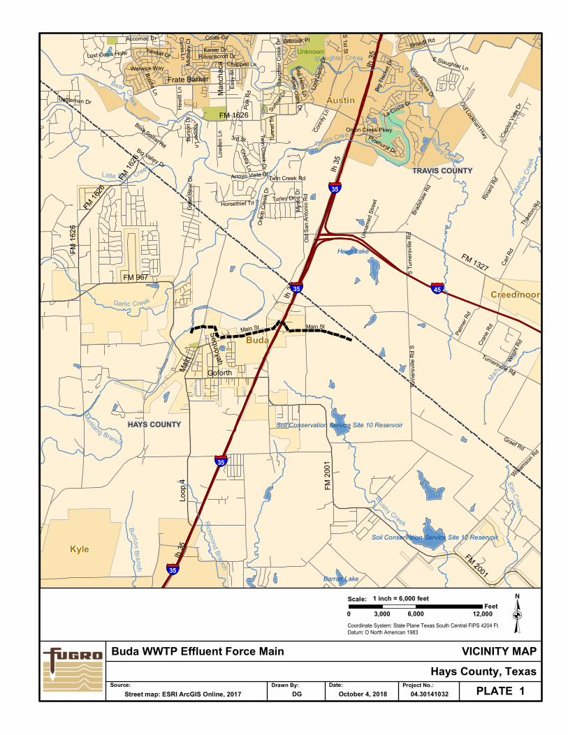
The pipeline alignment is approximately 15,000 linear feet and will be installed from the
existing City of Buda WWTP travelling east along Main Street crossing IH-35. The pipeline will
be installed primarily with open-cut excavation techniques. Trenchless techniques will be utilized
in three (3) locations. The project location is shown on the Vicinity Map, Plate 1.
AUTHORIZATION
The geotechnical investigation was authorized on July 7, 2018 by Mr. Martin Rambaugh,
P.E., Project Manager of AECOM with formal acceptance of our proposal dated May, 8, 2014.
The proposal outlines the scope of our services for the project.
PURPOSE AND SCOPE
The purpose of the investigation was to obtain adequate subsurface information to
identify geotechnical and geologic conditions along the project alignment, provide geotechnical
recommendations for earthwork, and specifications for the utility installations. This was
accomplished with a three phase study including: 1) a field investigation for determining general
subsurface conditions and obtaining representative samples for classification and testing,
2) a laboratory testing program to aid in the classification of subsurface strata and to establish
engineering properties of the strata encountered, and 3) analyses of field and laboratory data to
develop geotechnical design and construction recommendations.
Field sampling methods, laboratory testing procedures, soil classifications and strata
descriptions were in general accordance with methods, procedures, and practices set forth by the
American Society for Testing and Materials, Annual Book of ASTM Standards, latest edition,
where applicable.
FIELD INVESTIGATION
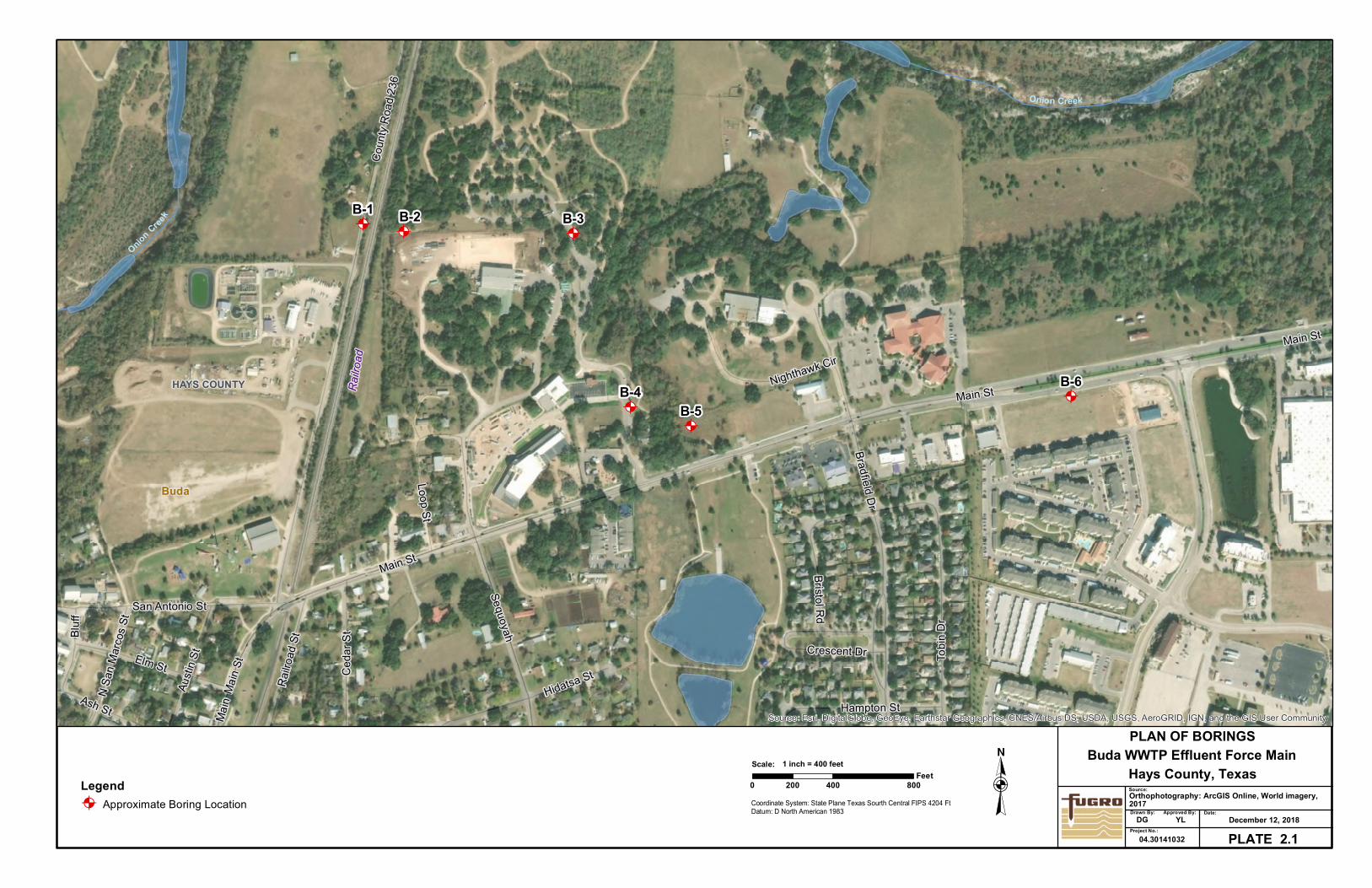
The field investigation consisted of drilling thirteen (13) borings (designated B-1 through
B-13) to depths of 15 to 30 feet below existing ground surface. Boring locations were
established in areas accessible to the drill rig and adjusted to avoid existing utilities, and were
Report No. 04.30141032
-2-
drilled approximately every 1,000 linear ft along the pipeline alignment. Boring locations are
shown on the Plan of Borings, Plate 2, and should be considered approximate.
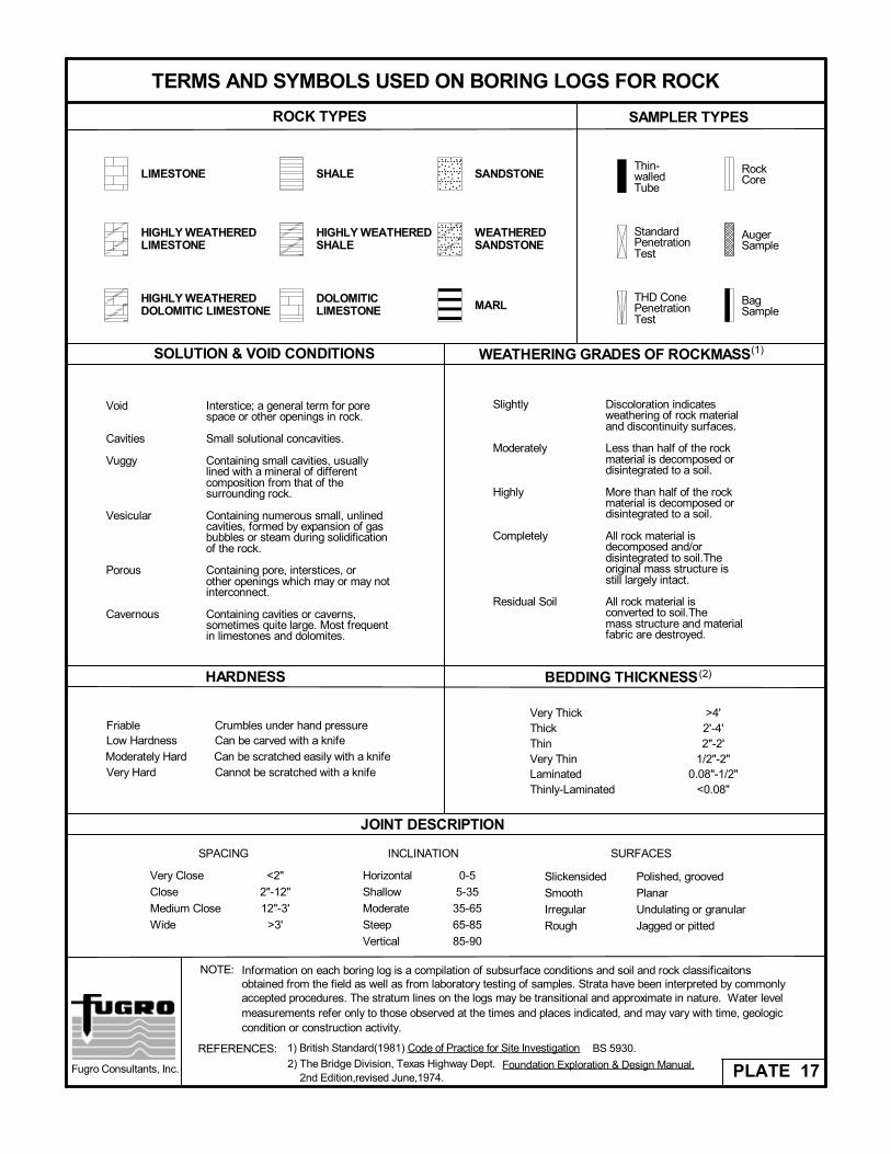
Detailed descriptions of the subsurface strata encountered are presented on the Logs of
Borings, Plates 3 through 15. Keys to Terms and Symbols used on the boring logs are set forth
on Plates 16 and 17. Pocket penetration values in tons per square foot, Standard Penetration
Test (SPT) N-values, and core recovery and Rock Quality Designation (ASTM D 6032) values, in
percent, are shown on the Logs of Borings under the appropriate column. Boring elevations
shown on the boring logs were obtained from Google Earth Professional and should be
considered approximate. Latitude and longitude coordinates were obtained in the field at each
boring location using a hand-held GPS device, accurate to about 3 horizontal meters, and are
presented in the notes on the bottom of the boring logs. Groundwater notes made during drilling
are also presented at the bottom of the logs.
The borings were drilled with a truck-mounted drill rig equipped with 1) continuous flight
augers for advancing the holes dry and recovering disturbed samples (ASTM D 1452),
2) seamless push tubes for obtaining relatively undisturbed soil samples of cohesive strata
(ASTM D 1587), 3) split-barrel samplers and drive-weight assembly for obtaining representative
samples and measuring the penetration resistance (N-values) of non-cohesive soil strata
(ASTM D 1586), and 4) double-tube wireline core barrels equipped with carbide bits for obtaining
2-inch diameter rock cores (ASTM D 2113).
LABORATORY TESTING
The laboratory testing program included identification and classification testing of strata
encountered in the subsurface. Soil classification tests, including Atterberg limit determinations
(ASTM D 4318) and partial grain-size analyses (ASTM D 422), were conducted on representative
samples of the soil strata. To determine compressive strength, unconfined compressive strength
tests (ASTM D 2166) were conducted on selected intact clay samples. Unconfined compression
tests (ASTM D 7012) were conducted on selected intact limestone core samples.
The classification and compressive tests included natural water content determinations (ASTM D
2216). The compression tests included unit dry weight determinations. The results of the tests
are tabulated on the boring logs at sample recovery depths. Brief descriptions of the test
procedures are provided in the following subsections.
Natural Water Content (ASTM D 2216)
Natural water content tests were performed on samples in which classification and/or
strength tests were performed. Each sample was visually classified in the laboratory. Natural
water contents are tabulated at sample depth on the boring logs.
Report No. 04.30141032
-3-
Atterberg Limits (ASTM D 4318)
Atterberg limit tests are classification tests that determine the liquid limit and plastic limit
of the soil fraction finer than the No. 40 sieve. The Atterberg limits are approximate water
contents at which the soil tested behaves in a specified manner. The liquid limit is determined by
measuring, in a standard device, the water content and number of blows required to close a
specific width groove cut in a remolded soil sample a specified length. The plastic limit is
determined by measuring the water content when threads of soil ⅛-inch in diameter begin to
crumble. The plasticity index, defined as the difference between the liquid and plastic limits,
indicates the degree of plasticity or the magnitude of the water content over which the soil
remains plastic. Liquid limit and plasticity index values are tabulated at sample depths on the
boring logs.
Sieve Analysis (ASTM D 422)
Grain-size characteristics of the natural soils were investigated by the determination of
the percent of soil passing the Nos. 4, 40 and 200 sieves. These tests were performed by
washing or sieving material through the respective sieves. The results are tabulated at sample
depth on the boring logs for the percent passing the Nos. 4 and 200 sieves.
Unconfined Compression Test of Cohesive Soil (ASTM D 2166)
In the unconfined compression test of cohesive soil, the specimen is sheared in
compression without confinement and drainage at a constant rate of axial deformation between
0.5 to 2.0 percent strain per minute and to produce failure in a test time less than 15 minutes.
The soil samples tested had diameters of about 2.8 inches and heights of about 5.6 inches. The
measured applied load was recorded for selected increments of deformation. Results of these
tests, including compressive strength, water content and unit dry weights, are tabulated on boring
logs at specimen recovery depth.
Unconfined Compression Strength of Rock Core Specimens (ASTM D 7012)
In the unconfined compression test of intact rock core specimens, a laterally unsupported
cylindrical rock specimen is loaded axially in compression to failure. The axial load is applied at a
constant rate of deformation to produce failure in a test time between 2 and 15 minutes. The
limestone cores tested were about 2 inches in diameter by 4 inches in length. The measured
applied load at failure is recorded. Results of these tests, including unconfined compressive
strength, water content, and unit dry weights, are tabulated on boring logs at core recovery
depth.
Report No. 04.30141032
-4-
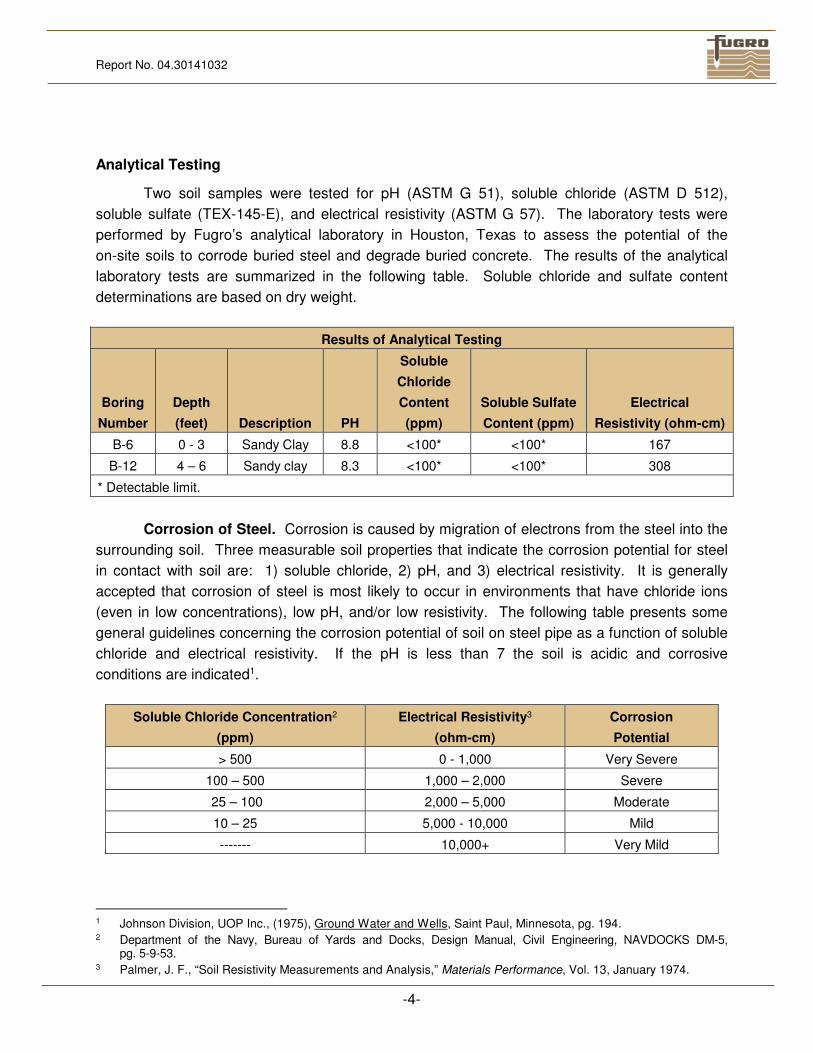
Analytical Testing
Two soil samples were tested for pH (ASTM G 51), soluble chloride (ASTM D 512),
soluble sulfate (TEX-145-E), and electrical resistivity (ASTM G 57). The laboratory tests were
performed by Fugro’s analytical laboratory in Houston, Texas to assess the potential of the
on-site soils to corrode buried steel and degrade buried concrete. The results of the analytical
laboratory tests are summarized in the following table. Soluble chloride and sulfate content
determinations are based on dry weight.
Results of Analytical Testing
Boring
Number
Depth
(feet) Description PH
Soluble
Chloride
Content
(ppm)
Soluble Sulfate
Content (ppm)
Electrical
Resistivity (ohm-cm)
B-6 0 - 3 Sandy Clay 8.8 <100* <100* 167
B-12 4 – 6 Sandy clay 8.3 <100* <100* 308
* Detectable limit.
Corrosion of Steel. Corrosion is caused by migration of electrons from the steel into the
surrounding soil. Three measurable soil properties that indicate the corrosion potential for steel
in contact with soil are: 1) soluble chloride, 2) pH, and 3) electrical resistivity. It is generally
accepted that corrosion of steel is most likely to occur in environments that have chloride ions
(even in low concentrations), low pH, and/or low resistivity. The following table presents some
general guidelines concerning the corrosion potential of soil on steel pipe as a function of soluble
chloride and electrical resistivity. If the pH is less than 7 the soil is acidic and corrosive
conditions are indicated1.
Soluble Chloride Concentration2
(ppm)
Electrical Resistivity3
(ohm-cm)
Corrosion
Potential
> 500 0 - 1,000 Very Severe
100 – 500 1,000 – 2,000 Severe
25 – 100 2,000 – 5,000 Moderate
10 – 25 5,000 - 10,000 Mild
------- 10,000+ Very Mild
1 Johnson Division, UOP Inc., (1975), Ground Water and Wells, Saint Paul, Minnesota, pg. 194. 2 Department of the Navy, Bureau of Yards and Docks, Design Manual, Civil Engineering, NAVDOCKS DM-5,
pg. 5-9-53. 3 Palmer, J. F., “Soil Resistivity Measurements and Analysis,” Materials Performance, Vol. 13, January 1974.
Report No. 04.30141032
-5-
Each variable should be used independently of the others when evaluating soil corrosion
potential. For example, it is not necessary to have a resistivity between 0 and 1,000 ohm-cm and
a pH of 2.0 to indicate a very high potential for corrosion potential.
A Corrosion Engineer should review the test results discussed herein when designing
appropriate methods of protecting buried steel.
Degradation of Concrete. The degradation of concrete is caused by chemical agents in
the soil or groundwater that react with concrete to either dissolve the cement paste or precipitate
larger compounds which cause cracking and flaking. The concentration of water-soluble sulfates
in the soils is a good indicator of the potential for chemical attack of concrete. The soluble
sulfate content in soil can be used to evaluate the need for protection of concrete based on the
following table:
Water Soluble Sulfate Content
In Soil4, (percent)
Water Soluble Sulfate Content
In Soil, (ppm)
Degradation
Potential
> 2.0 > 20,000 Very Severe
0.2 – 2.0 2,000 – 20,000 Severe
0.1 – 0.2 1,000 – 2,000 Moderate
0.0 – 0.1 0 – 1,000 Mild
A Corrosion Engineer should be consulted to determine if sulfate resistant concrete is
warranted.
Strata Descriptions
Descriptions of strata made in the field at the time the borings were drilled were modified
in accordance with results of laboratory tests and visual examination in the laboratory.
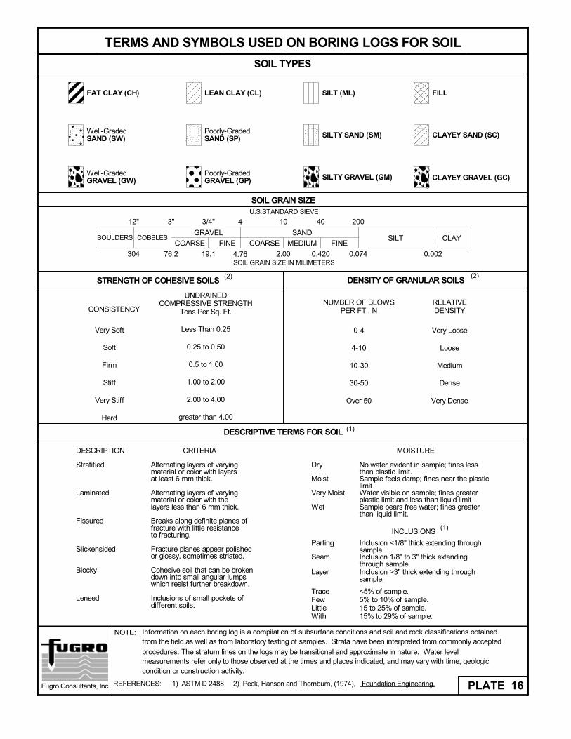
Recovered soil samples were examined and classified in general accordance with ASTM D 2487
and described as recommended in ASTM D 2488. Rock strata were classified in general
accordance with “Rock Classification and Description”, Chapter 1, Section 5, NAVFAC DM-75.
Classifications of the soils and finalized descriptions of both rock and soil strata are shown on the
logs of borings.
4 American Concrete Institute, ACI Manual of Concrete Practice, 1998, Part 1, Materials and General Properties of
Concrete, Section 201.2R-10. 5 U.S. Navy (1971) Design Manual - Soil Mechanics, Foundations, and Earth Structures, NAVFAC DM-7.
Report No. 04.30141032
-6-
SITE AND SUBSURFACE CONDITIONS
Physiography
The pipeline alignment will begin at the existing City of Buda WWTP and extend east
along Main Street crossing IH-35. The alignment is located in residential and commercial areas,
surrounded by parking, homes, trees, and commercial buildings. Onion Creek flows in the north,
generally parallel to the project alignment. A few detention ponds are also located along the
project alignment. Existing grade along the pipeline alignment ranges approximately from 688 to
764 feet.
Geology
According to published geologic mapping6 and the subsurface soil conditions encountered
during this investigation, the alignment is underlain by Alluvium, Eagle Ford shale, and the Buda
Limestone formation near IH 35 and west of IH 35. East of IH 35, the alignment is underlain by
residual soil, followed by Taylor clay of the Ozan Formation. A discussion of each geologic
formation is provided in the following subsections, youngest to oldest.
Alluvium. The alluvium, also referred to as terrace deposits, consists of unconsolidated
and interbedded layers of clay, silt, sand, and gravel. These deposits can include cobbles and
boulders, and layers of cemented conglomerate. In general, alluvium and terrace deposits grade
from more fine-grained clay and silt to more coarse-grained sand and gravel with depth. Sand
and gravel lenses and layers may be present at erratic locations within fine-grained strata due to
the depositional nature of the alluvium. The contact with the underlying parent formation
(bedrock) is erosional in nature and can vary by several feet over relatively short distances.
Oftentimes, at the base of the terrace deposit strata, cobbles and/or boulders are present.
Eagle Ford. The Eagle Ford formation is comprised of four members from youngest to
oldest: South Bosque shale, Bouldin flags, Cloice shale, and Pepper shale. These members are
typically not mapped separately, although they have disparate physical properties. The South
Bosque member is a calcareous, marly claystone, which is primarily montmorillonitic clay. The
Bouldin flags member consists of interbedded montmorillonitic shale and limestone flags. The
Cloice shale is a fissile, gray, montmorillonitic, silty shale formation. The Pepper shale is a
montmorillonitic, noncalcareous, unctuous, black claystone, which on the weathered surface
contains the minerals selenite and jarosite. The Eagle Ford clays and shales are highly plastic,
with a very high shrink/swell potential if subjected to moisture changes.
6 Francis, W.L. (1981), “Geologic Atlas of Texas, Austin Sheet,” Bureau of Economic Geology, The University of
Texas at Austin, map and explanatory bulletin.
Report No. 04.30141032
-7-
Buda Limestone. The Buda formation consists of an upper hard, resistant, fine-grained,
burrowed, glauconitic, shell-fragment limestone and a lower marly, nodular, and less resistant
limestone. The Buda limestone is colored with shades of tan to orange-brown that resemble
discoloration caused by heating.
Taylor Clay. The Taylor clay of Ozan Formation (Ko) generally consists of highly plastic,
calcareous clay and shale. The Taylor clays are generally gray to light gray in color, blocky, and
contain glauconitic nodules.
Site Stratigraphy and Engineering Properties
The subsurface conditions can best be understood by a thorough review of the boring
logs presented on Plates 3 through 15. A brief discussion of the subsurface conditions
encountered in the project alignment is provided in the following sections.
Near IH-35 and West of IH 35 (Borings B-1 to B-10). Generally, these borings
encountered various fill materials underlain by reddish brown to tan clayey sand with gravel
(alluvium), further underlain by gray Eagle Ford shale and light gray Buda limestone. It is
sometimes difficult to distinguish fill materials from native soils unless foreign material is present.
The fill material was encountered at depths of 2 to 13 feet and was typically described as
brown to tan clayey gravel/sand to lean or fat clay with gravel. Measured liquid limits ranged
from 28 to 82, plasticity indices ranged from 11 to 52, and percent fines (material passing the
No. 200 sieve) ranged from 15 to 86. Standard penetration test (SPT) “N” values ranged from
5 to 50 blows over penetration of 1 inch indicating very loose to very dense consistency.
The alluvium was encountered beneath the surficial fill and extended to the depths of
11 to 24 feet, and was typically described as reddish brown to tan clayey sand with gravel.
Measured liquid limits ranged from 25 to 52, plasticity indices ranged from 6 to 35, and percent
fines ranged from 5 to 95. SPT “N” values ranged from 9 to 50 blows for 2 inches of penetration
indicating loose to very dense consistency.
Gray shale of the Eagle Ford formation was encountered beneath the alluvium material at
Borings B-1, B-2, B-4, B-5, B-8, and B-9 and extended to the termination depths of the borings
(except at Boring B-5). SPT “N” values ranged from 51 to 50 blows over 2 inches of penetration
indicating very dense consistency.
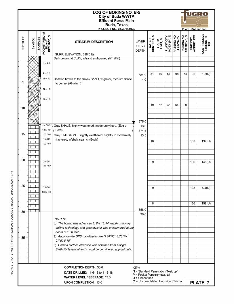
Gray weathered limestone of the Buda formation was encountered in Boring B-5 at a
depth of 14 feet and extended to the boring termination depth of 30 feet. Core recovery values
Report No. 04.30141032
-8-
of 100 percent and RQD values varying from 85 to 100 percent were measured. Measured
unconfined compressive strengths ranged from 5.4 to 158 tons per square foot (tsf).
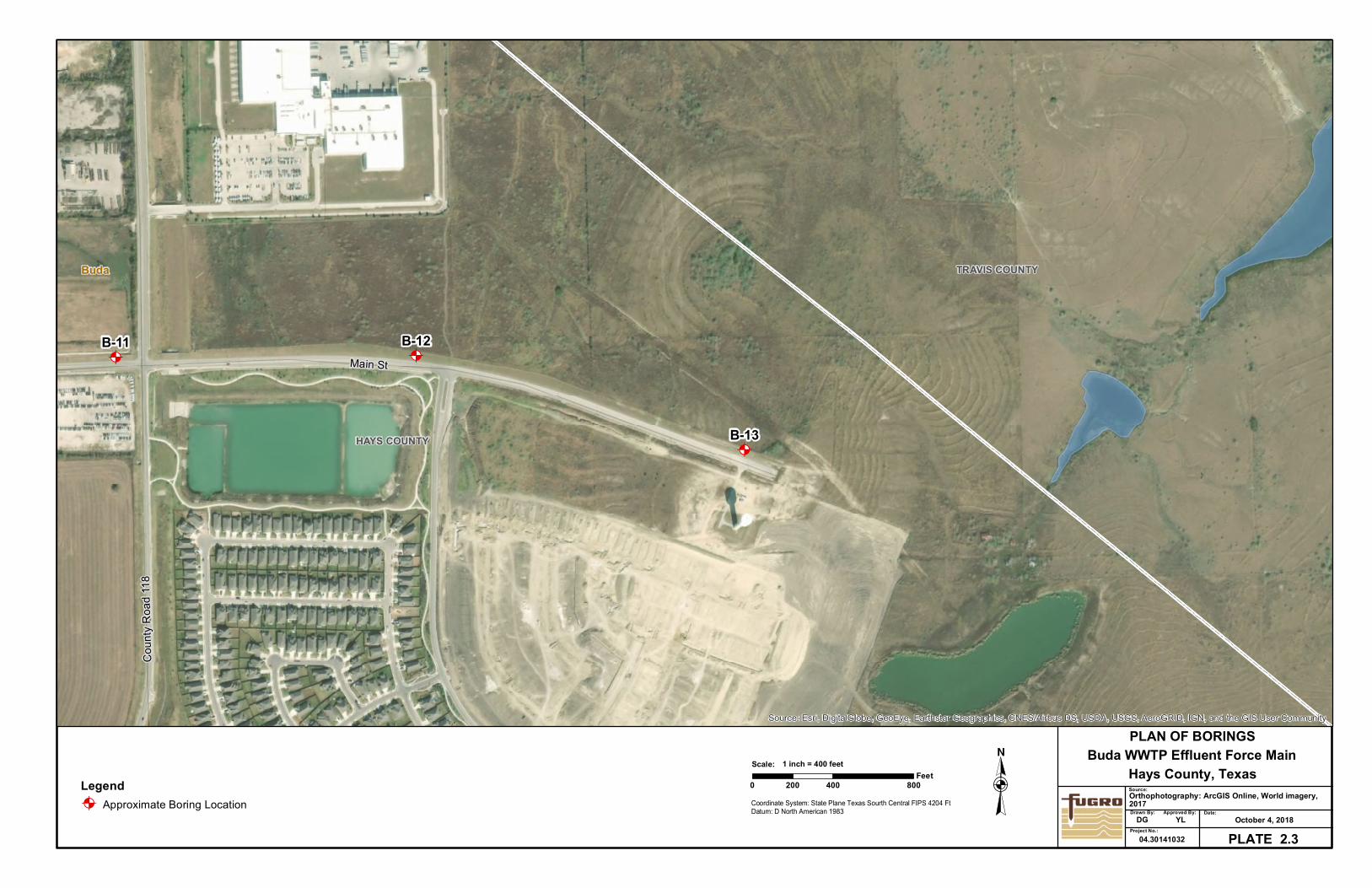
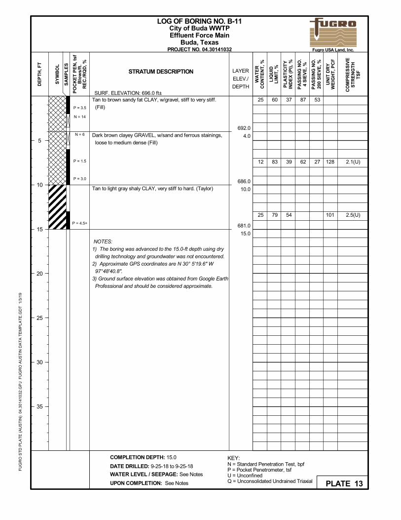
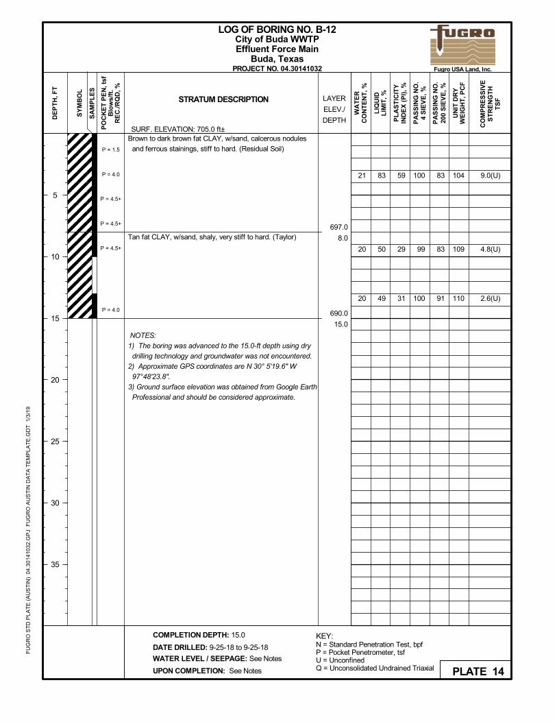
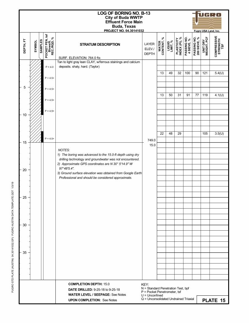
East IH-35 Borings (B-11 through B-13). The borings encountered fill materials at
Boring B-11 to depth of 10 feet and brown to dark brown residual soil at Boring B-12 to depth of
8 feet underlain by tan to light gray Taylor clay to the termination depth at 15 feet below ground
surface.
Fill material was encountered in Boring B-11 to a depth of 10 feet and was described as
dark brown to tan clayey gravel with sand to fat clay with gravel. Liquid limits of 60 and 83 were
measured, with corresponding plasticity indices of 37 and 39, and percent fines of 53 and 27.
SPT “N” values ranged from 6 to 14 indicating loose to medium dense consistency.
Residual soil was encountered in Boring B-12 to a depth of 8 feet and was described as
brown to dark brown fat clay, stiff to very hard, with ferrous staining. A liquid limit of 83 was
measured, with corresponding plasticity index of 59, and percent fines of 83. An unconfined
compressive strength of 9.0 tsf was measured.
Tan to light gray Taylor clay was encountered beneath the fill at Boring B-11, beneath the
residual soil at Boring B-12, and at ground surface at Boring B-13, extending to the termination
depth of 15 feet. Measured liquid limits ranged from 48 to 79 percent, plasticity indices (PI)
ranged from 29 to 54 percent, and percent fines ranged from 77 to 91 percent. Unconfined
compressive strengths ranged from 2.5 to 5.4 (average 3.8) tsf.
Groundwater Occurrence
As noted on the logs, groundwater was encountered in four borings (B-4, B-5, B-8 and
B-9). At boring B-5, the introduction of drilling fluid (water) for the rock coring operations
prohibited direct groundwater observations in the rock-like strata.
One should note that the direct groundwater observations reported herein are very short
term and should not be interpreted as a “groundwater study”. The quantity of perched or
transient groundwater is generally strongly influenced by antecedent rainfall conditions and the
proximity to nearby creeks and drainage ways. Groundwater quantities may be particularly
severe in areas of faults especially following rain events. The contractor should be made aware
of the possible presence of groundwater in excavations, which may be severe and in
communication with surface waters following rain events.
Report No. 04.30141032
-9-
CONSTRUCTION CONSIDERATIONS
The force main will include about 15,000 linear feet of 20-inch diameter pipe, at depths
ranging primarily from 10 to 15 feet. The pipe will be installed primarily by conventional open-cut
excavation techniques. Trenchless crossing techniques will be utilized in three (3) locations.
Recommendations for pipe bedding and trench backfill, and comments regarding excavation
potential and temporary sloping are provided in the following sections. As the City of Buda does
not have its own specifications, City of Austin specifications are referenced herein.
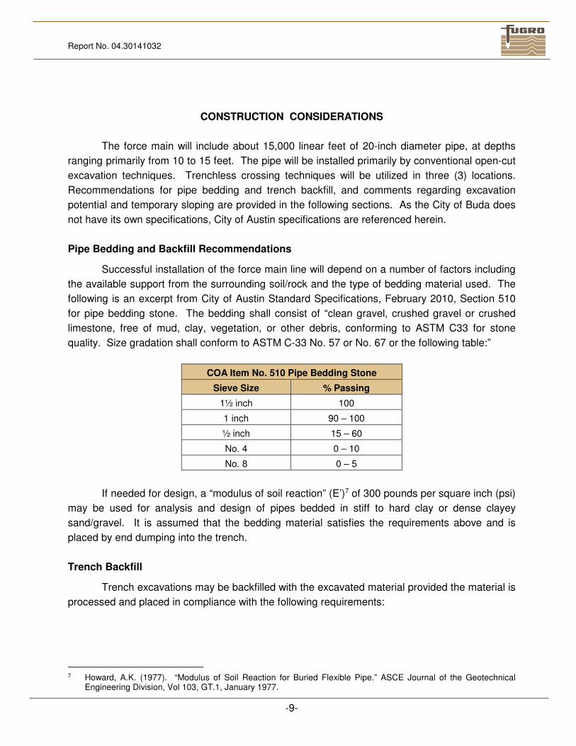
Pipe Bedding and Backfill Recommendations
Successful installation of the force main line will depend on a number of factors including
the available support from the surrounding soil/rock and the type of bedding material used. The
following is an excerpt from City of Austin Standard Specifications, February 2010, Section 510
for pipe bedding stone. The bedding shall consist of “clean gravel, crushed gravel or crushed
limestone, free of mud, clay, vegetation, or other debris, conforming to ASTM C33 for stone
quality. Size gradation shall conform to ASTM C-33 No. 57 or No. 67 or the following table:”
COA Item No. 510 Pipe Bedding Stone
Sieve Size % Passing
1½ inch 100
1 inch 90 – 100
½ inch 15 – 60
No. 4 0 – 10
No. 8 0 – 5
If needed for design, a “modulus of soil reaction” (E’)7 of 300 pounds per square inch (psi)
may be used for analysis and design of pipes bedded in stiff to hard clay or dense clayey
sand/gravel. It is assumed that the bedding material satisfies the requirements above and is
placed by end dumping into the trench.
Trench Backfill
Trench excavations may be backfilled with the excavated material provided the material is
processed and placed in compliance with the following requirements:
7 Howard, A.K. (1977). “Modulus of Soil Reaction for Buried Flexible Pipe.” ASCE Journal of the Geotechnical
Engineering Division, Vol 103, GT.1, January 1977.
Report No. 04.30141032
-10-
1. Excavated trench material should be free of debris, clay lumps, excessive organics,
and other deleterious material, and be screened to limit the maximum particle size to
3 inches.
2. Compact the backfill to 95% of the maximum dry density determined using TxDOT
Test Method TEX-114-E for clayey soils and TEX-113-E for gravelly soils.
Compacted lift thicknesses should not be more than 6 inches. Water contents of the
compacted backfill should be within ±2% of optimum.
3. Density testing should be performed on the backfill after each horizontal lift and not by
“potholing.” This requirement will necessitate protection for the density testing
technician in trenches deeper than 5 feet by means of a trench safety system.
Excavation Potential
Excavation through the fill, alluvium, shale and completely weathered limestone should
proceed without significant difficulty, although hard limestone seams and layers may be present
within the completely weathered limestone. Advancement into the limestone will proceed with
greater difficulty. Based on the rock core recovery, RQD values, and measured unconfined
compressive strengths of rock core samples ranging from 5.4 to 158 tsf (average 113 tsf) along
the proposed alignment, the limestone is rippable to marginally rippable with a Caterpillar D-9 or
equivalent. Trench excavation into the limestone will require heavy-duty excavators, rock saws,
hoe rams or other similar equipment.
Temporary Trench Excavations, Support, and Groundwater
Based on proposed excavation depths of 10 to 15 feet, excavations will likely extend
through overburden soils and into weathered shale. As discussed previously, the lower
elevations of the soils just above the shale/limestone bedrock, particularly near the creek, may
consist of saturated granular soils which are susceptible to “raveling” or “running” into the
excavation. This condition will be further complicated by the likely presence of groundwater in
potential communication with the nearby creek. Groundwater infiltration may also be problematic
within faults and fractures of the limestone stratum, particularly if in communication with the
nearby creek. If excessive groundwater is encountered during excavation, the geotechnical
engineer should be contacted to document the condition and to provide alternatives for suitable
groundwater control and pipe placement.
Trench safety is the sole responsibility of the contractor and he is required to retain the
services of a licensed professional engineer to design his trench safety system to comply with
applicable OSHA requirements.
Report No. 04.30141032
-11-
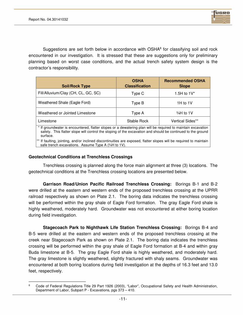
Suggestions are set forth below in accordance with OSHA8 for classifying soil and rock
encountered in our investigation. It is stressed that these are suggestions only for preliminary
planning based on worst case conditions, and the actual trench safety system design is the
contractor’s responsibility.
Soil/Rock Type
OSHA
Classification
Recommended OSHA
Slope
Fill/Alluvium/Clay (CH, CL, GC, SC) Type C 1.5H to 1V*
Weathered Shale (Eagle Ford) Type B 1H to 1V
Weathered or Jointed Limestone Type A ¾H to 1V
Limestone Stable Rock Vertical Sides**
* If groundwater is encountered, flatter slopes or a dewatering plan will be required to maintain excavation safety. This flatter slope will control the sloping of the excavation and should be continued to the ground surface.
** If faulting, jointing, and/or inclined discontinuities are exposed, flatter slopes will be required to maintain safe trench excavations. Assume Type A (¾H to 1V).
Geotechnical Conditions at Trenchless Crossings
Trenchless crossing is planned along the force main alignment at three (3) locations. The
geotechnical conditions at the Trenchless crossing locations are presented below.
Garrison Road/Union Pacific Railroad Trenchless Crossing: Borings B-1 and B-2
were drilled at the eastern and western ends of the proposed trenchless crossing at the UPRR
railroad respectively as shown on Plate 2.1. The boring data indicates the trenchless crossing
will be performed within the gray shale of Eagle Ford formation. The gray Eagle Ford shale is
highly weathered, moderately hard. Groundwater was not encountered at either boring location
during field investigation.
Stagecoach Park to Nighthawk Life Station Trenchless Crossing: Borings B-4 and
B-5 were drilled at the eastern and western ends of the proposed trenchless crossing at the
creek near Stagecoach Park as shown on Plate 2.1. The boring data indicates the trenchless
crossing will be performed within the gray shale of Eagle Ford formation at B-4 and within gray
Buda limestone at B-5. The gray Eagle Ford shale is highly weathered, and moderately hard.
The gray limestone is slightly weathered, slightly fractured with shaly seams. Groundwater was
encountered at both boring locations during field investigation at the depths of 16.3 feet and 13.0
feet, respectively.
8 Code of Federal Regulations Title 29 Part 1926 (2003), “Labor”, Occupational Safety and Health Administration,
Department of Labor, Subpart P - Excavations, pgs 373 – 410.
Report No. 04.30141032
-12-
IH-35 Trenchless Crossing: Borings B-8 and B-9 were drilled at the eastern and
western ends of the proposed trenchless crossing at IH-35 as shown on Plate 2.2. The boring
data indicates the trenchless crossing will be performed within the gray shale of Eagle Ford
formation. The gray Eagle Ford shale is highly weathered, moderately hard. Groundwater was
encountered at both boring locations during field investigation at the depths of 17.2 feet and 17.0
feet, respectively.
CONDITIONS
Since some variation was found in subsurface conditions at the boring locations, all
parties involved should take notice that even more variation may be encountered between boring
locations. Statements in the report as to subsurface variation over given areas are intended only
as estimations from the data obtained at specific boring locations. The design and construction
recommendations contained in this report supersede all previous verbal or written geotechnical
recommendations provided by Fugro for this project.
The professional services that form the basis for this report have been performed using
that degree of care and skill ordinarily exercised, under similar circumstances, by reputable
geotechnical engineers practicing in the same locality. No warranty, express or implied, is made
as the professional advice set forth. Fugro's scope of work does not include the investigation,
detection, or design related to the presence of any biological pollutants. The term 'biological
pollutants' includes, but is not limited to, mold, fungi, spores, bacteria, and viruses, and the
byproducts of any such biological organisms.
The results, conclusions, and recommendations contained in this report are directed at,
and intended to be utilized within, the scope of work contained in the proposal letter executed by
Fugro USA Land, Inc. and client. This report is not intended to be used for any other purposes.
Fugro USA Land, Inc. makes no claim or representation concerning any activity or condition
falling outside the specified purposes to which this report is directed, said purposes being
specifically limited to the scope of work as defined in said agreement. Inquiries as to said scope
of work or concerning any activity or condition not specifically contained therein should be
directed to Fugro USA Land, Inc. for a determination and, if necessary, further investigation.
P L A T E S
Soil Conservation Service Site 12 Reservoir
Barron Lake
Soil Conservation Service Site 10 Reservoir
Heep Lake
Brushy Creek
ElmCreek
Richmond Branch
BuntonB ranch
Onion Creek
Bear Creek
Rinard Creek
Garlic Creek
Slaughter Creek
Little Bear Creek
Maha Creek
Marble
Cree
k
Mustang Branch
FM 20
01
Loop
4
FM 967
GoforthMain
Sequoyah
FM 16
26
Ih 35
FM 16
26
Ih 35
FM 16
26
FM 2001
§̈¦35
§̈¦35
§̈¦45
§̈¦35
Ih 35
FM 1327
FM 1626
Manc
haca
Frate Barker
Ih 35
Turnersville Rd
Old Lockhart Hwy
Old S
an An
tonio
Rd
Bradsh
aw Rd
Brodie Ln
Wright R
d
Graef Rd
Brandt Rd
S Turn
ersvill
e Rd
Carl R
d
Palme
r Rd
Twin Creek Rd
Turley Dr
Lowd
en Ln Pinehurst Dr
Mysti
c Dr
S 1st St
Crane
RdCa
pitol V
iew Dr
Rinard
Rd
Polk
Rd
Yandall Dr
Hewit
t Ln
Onion
Cree
k Dr
Chappell Ln
Tunn
el Trl
Lost Oasis Holw
Easy
St
Conro
y Ln
Slaug
hter C
reek D
r
Cholla Ln
E Slaughter Ln
Sunse
t Dr
Thaxto
n Rd
Bilbrook Pl
Williamson
Rd
Bliss Spillar Rd
River Oaks Dr
La Costa Dr
Kaiser Dr
Horsethief Trl
Ravenscroft Dr
Burso
n Dr
Arroyo Vista Dr
Turne
rsville
Rd S
Accomac Dr
Big Th
icket
Dr
Unna
med S
treet
Topper Ln
Midb
ury C
t
Twin Creek Dr
Currin Ln
Onion Creek Pkwy
Sea Hero Ln
Grea
t Bea
r Dr
Warwick Way
3rd St
Wild Dunes Dr
Big Valley Dr
Coats Cir
Lord
Derby
Dr
Cattleman Dr
HAYS COUNTY
TRAVIS COUNTY
Unknown
Buda
Austin
Kyle
Creedmoor§̈¦35
0 6,000
Coordinate System: State Plane Texas South Central FIPS 4204 Ft Datum: D North American 1983
12,0003,000Feet
1 inch = 6,000 feetScale:
Buda WWTP Effluent Force Main
Drawn By:
VICINITY MAP
Source: Project No.:04.30141032 PLATE 1
Hays County, TexasDate:
October 4, 2018DGStreet map: ESRI ArcGIS Online, 2017
Main StMain St
AA A
A
A
A
B-6B-5
B-4
B-3B-2B-1
Onion Creek
Onion Creek
Main St
Bradfield Dr
Coun
ty Ro
ad 23
6
Tobin
Dr
Elm StHidatsa St
Bluff
Ceda
r St
San Antonio St
Loop St
Austin
St
Ash St Hampton St
Railro
ad St
Bristol Rd
Nighthawk Cir
Crescent Dr
N San
Marc
os St
Main St
Sequoyah
Main
StMa
in
Main St
HAYS COUNTY
Buda
Railro
ad
Source: Esri, DigitalGlobe, GeoEye, Earthstar Geographics, CNES/Airbus DS, USDA, USGS, AeroGRID, IGN, and the GIS User Community
0 400 800200Feet
1 inch = 400 feetScale:
LegendA Approximate Boring Location
PLAN OF BORINGS
Hays County, Texas
Drawn By:
Buda WWTP Effluent Force MainSource:Orthophotography: ArcGIS Online, World imagery,2017
Project No.:04.30141032 PLATE 2.1
Date:December 12, 2018DG
Coordinate System: State Plane Texas Sourth Central FIPS 4204 FtDatum: D North American 1983 Approved By:
YL

A
A
A
A
A
A
B-9
B-8
B-7
B-6
B-11B-10
Onion Creek
Main St
Coun
ty Ro
ad 11
8
Old San Antonio Rd
Bar K DrPit
Stop
TrceMain St
Main St
Main St
§̈¦35
§̈¦35
HAYS COUNTY
Buda
Source: Esri, DigitalGlobe, GeoEye, Earthstar Geographics, CNES/Airbus DS, USDA, USGS, AeroGRID, IGN, and the GIS User Community
0 400 800200Feet
1 inch = 400 feetScale:
LegendA Approximate Boring Location
PLAN OF BORINGS
Hays County, Texas
Drawn By:
Buda WWTP Effluent Force MainSource:Orthophotography: ArcGIS Online, World imagery,2017
Project No.:04.30141032 PLATE 2.2
Date:October 4, 2018DG
Coordinate System: State Plane Texas Sourth Central FIPS 4204 FtDatum: D North American 1983 Approved By:
YL
A A
A
B-13
B-12B-11Main St
Coun
ty Ro
ad 11
8
HAYS COUNTY
TRAVIS COUNTYBuda
Source: Esri, DigitalGlobe, GeoEye, Earthstar Geographics, CNES/Airbus DS, USDA, USGS, AeroGRID, IGN, and the GIS User Community
0 400 800200Feet
1 inch = 400 feetScale:
LegendA Approximate Boring Location
PLAN OF BORINGS
Hays County, Texas
Drawn By:
Buda WWTP Effluent Force MainSource:Orthophotography: ArcGIS Online, World imagery,2017
Project No.:04.30141032 PLATE 2.3
Date:October 4, 2018DG
Coordinate System: State Plane Texas Sourth Central FIPS 4204 FtDatum: D North American 1983 Approved By:
YL
49
66
37
25687.0
6.0
682.0
11.0
678.0
15.0
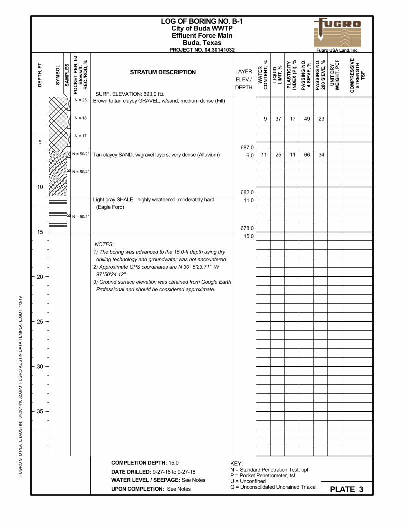
Brown to tan clayey GRAVEL, w/sand, medium dense (Fill)
Tan clayey SAND, w/gravel layers, very dense (Alluvium)
Light gray SHALE, highly weathered, moderately hard
(Eagle Ford)
NOTES:
1) The boring was advanced to the 15.0-ft depth using dry
drilling technology and groundwater was not encountered.
2) Approximate GPS coordinates are N 30° 5'23.71" W
97°50'24.12".
3) Ground surface elevation was obtained from Google Earth
Professional and should be considered approximate.
17
11
23
34
N = 25
N = 18
N = 17
N = 50/2"
N = 50/4"
N = 50/4"
9
11
UN
IT D
RY
WE
IGH
T, P
CF
PA
SS
ING
NO
.4
SIE
VE
, %
LIQ
UID
LIM
IT, %LAYER
ELEV./
DEPTH
SY
MB
OL
SA
MP
LE
SSTRATUM DESCRIPTION
DATE DRILLED: 9-27-18 to 9-27-18
PL
AS
TIC
ITY
IND
EX
(P
I), %
PA
SS
ING
NO
.20
0 S
IEV
E, %
PO
CK
ET
PE
N, t
sfB
low
s/ft
.R
EC
./RQ
D, %
WA
TE
RC
ON
TE
NT
, %
DE
PT
H, F
T
5
10
15
20
25
30
35
WATER LEVEL / SEEPAGE: See Notes
UPON COMPLETION: See Notes
COMPLETION DEPTH: 15.0
LOG OF BORING NO. B-1
PROJECT NO. 04.30141032
Effluent Force MainBuda, Texas
CO
MP
RE
SS
IVE
ST
RE
NG
TH
TS
F
KEY:N = Standard Penetration Test, bpfP = Pocket Penetrometer, tsfU = UnconfinedQ = Unconsolidated Undrained Triaxial PLATE 3
City of Buda WWTP
SURF. ELEVATION: 693.0 ft±
Fugro USA Land, Inc.
FU
GR
O S
TD
PL
AT
E (
AU
ST
IN)
04.
301
410
32.G
PJ
FU
GR
O A
US
TIN
DA
TA
TE
MP
LAT
E.G
DT
1/3
/19
43
51
34
30
697.0
2.0
687.0
12.0
679.0
20.0
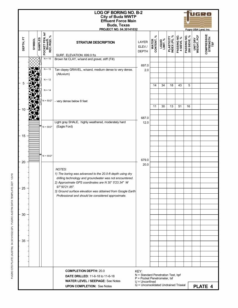
Brown fat CLAY, w/sand and gravel, stiff (Fill)
Tan clayey GRAVEL, w/sand, medium dense to very dense.
(Alluvium)
- very dense below 8 feet
Light gray SHALE, highly weathered, moderately hard
(Eagle Ford)
NOTES:
1) The boring was advanced to the 20.0-ft depth using dry
drilling technology and groundwater was not encountered.
2) Approximate GPS coordinates are N 30° 5'23.34" W
97°50'21.85".
3) Ground surface elevation was obtained from Google Earth
Professional and should be considered approximate.
18
13
5
16
N = 10
N = 15
N = 12
N = 14
N = 50/2"
N = 50/2"
N = 50/2"
14
11
UN
IT D
RY
WE
IGH
T, P
CF
PA
SS
ING
NO
.4
SIE
VE
, %
LIQ
UID
LIM
IT, %LAYER
ELEV./
DEPTH
SY
MB
OL
SA
MP
LE
SSTRATUM DESCRIPTION
DATE DRILLED: 11-6-18 to 11-6-18
PL
AS
TIC
ITY
IND
EX
(P
I), %
PA
SS
ING
NO
.20
0 S
IEV
E, %
PO
CK
ET
PE
N, t
sfB
low
s/ft
.R
EC
./RQ
D, %
WA
TE
RC
ON
TE
NT
, %
DE
PT
H, F
T
5
10
15
20
25
30
35
WATER LEVEL / SEEPAGE: See Notes
UPON COMPLETION: See Notes
COMPLETION DEPTH: 20.0
LOG OF BORING NO. B-2
PROJECT NO. 04.30141032
Effluent Force MainBuda, Texas
CO
MP
RE
SS
IVE
ST
RE
NG
TH
TS
F
KEY:N = Standard Penetration Test, bpfP = Pocket Penetrometer, tsfU = UnconfinedQ = Unconsolidated Undrained Triaxial PLATE 4
City of Buda WWTP
SURF. ELEVATION: 699.0 ft±
Fugro USA Land, Inc.
FU
GR
O S
TD
PL
AT
E (
AU
ST
IN)
04.
301
410
32.G
PJ
FU
GR
O A
US
TIN
DA
TA
TE
MP
LAT
E.G
DT
1/3
/19
68
57
56
49
28
28
695.0
2.0
682.0
15.0
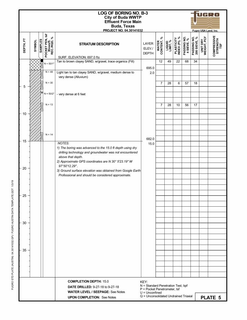
Tan to brown clayey SAND, w/gravel, trace organics (Fill)
Light tan to tan clayey SAND, w/gravel, medium dense to
very dense (Alluvium)
- very dense at 6 feet
NOTES:
1) The boring was advanced to the 15.0 ft depth using dry
drilling technology and groundwater was not encountered
above that depth.
2) Approximate GPS coordinates are N 30° 5'23.19" W
97°50'12.29" .
3) Ground surface elevation was obtained from Google Earth
Professional and should be considered approximate.
22
6
10
34
18
17
N = 50/1"
N = 48
N = 30
N = 50/2"
N = 13
N = 14
12
7
7
UN
IT D
RY
WE
IGH
T, P
CF
PA
SS
ING
NO
.4
SIE
VE
, %
LIQ
UID
LIM
IT, %LAYER
ELEV./
DEPTH
SY
MB
OL
SA
MP
LE
SSTRATUM DESCRIPTION
DATE DRILLED: 9-27-18 to 9-27-18
PL
AS
TIC
ITY
IND
EX
(P
I), %
PA
SS
ING
NO
.20
0 S
IEV
E, %
PO
CK
ET
PE
N, t
sfB
low
s/ft
.R
EC
./RQ
D, %
WA
TE
RC
ON
TE
NT
, %
DE
PT
H, F
T
5
10
15
20
25
30
35
WATER LEVEL / SEEPAGE: See Notes
UPON COMPLETION: See Notes
COMPLETION DEPTH: 15.0
LOG OF BORING NO. B-3
PROJECT NO. 04.30141032
Effluent Force MainBuda, Texas
CO
MP
RE
SS
IVE
ST
RE
NG
TH
TS
F
KEY:N = Standard Penetration Test, bpfP = Pocket Penetrometer, tsfU = UnconfinedQ = Unconsolidated Undrained Triaxial PLATE 5
City of Buda WWTP
SURF. ELEVATION: 697.0 ft±
Fugro USA Land, Inc.
FU
GR
O S
TD
PL
AT
E (
AU
ST
IN)
04.
301
410
32.G
PJ
FU
GR
O A
US
TIN
DA
TA
TE
MP
LAT
E.G
DT
1/3
/19
50
75
60
28
35
24
689.0
5.0
675.5
18.5
674.0
20.0
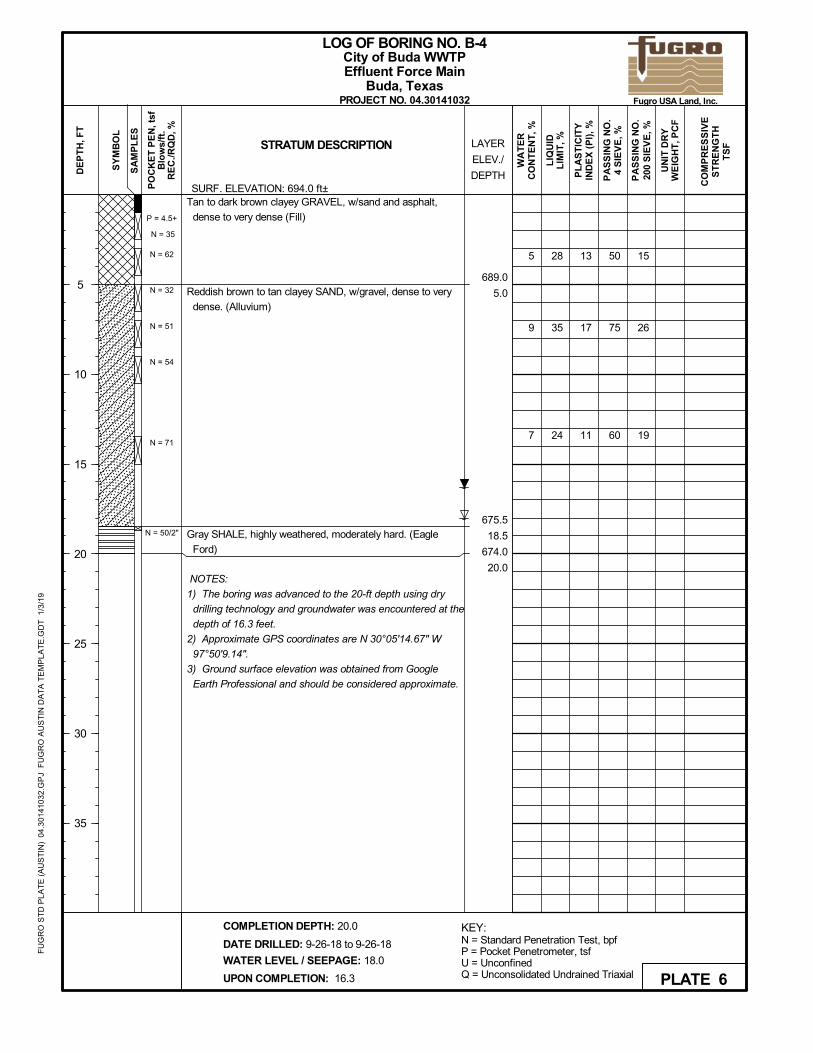
Tan to dark brown clayey GRAVEL, w/sand and asphalt,
dense to very dense (Fill)
Reddish brown to tan clayey SAND, w/gravel, dense to very
dense. (Alluvium)
Gray SHALE, highly weathered, moderately hard. (Eagle
Ford)
NOTES:
1) The boring was advanced to the 20-ft depth using dry
drilling technology and groundwater was encountered at the
depth of 16.3 feet.
2) Approximate GPS coordinates are N 30°05'14.67" W
97°50'9.14".
3) Ground surface elevation was obtained from Google
Earth Professional and should be considered approximate.
13
17
11
15
26
19
P = 4.5+
N = 35
N = 62
N = 32
N = 51
N = 54
N = 71
N = 50/2"
5
9
7
UN
IT D
RY
WE
IGH
T, P
CF
PA
SS
ING
NO
.4
SIE
VE
, %
LIQ
UID
LIM
IT, %LAYER
ELEV./
DEPTH
SY
MB
OL
SA
MP
LE
SSTRATUM DESCRIPTION
DATE DRILLED: 9-26-18 to 9-26-18
PL
AS
TIC
ITY
IND
EX
(P
I), %
PA
SS
ING
NO
.20
0 S
IEV
E, %
PO
CK
ET
PE
N, t
sfB
low
s/ft
.R
EC
./RQ
D, %
WA
TE
RC
ON
TE
NT
, %
DE
PT
H, F
T
5
10
15
20
25
30
35
WATER LEVEL / SEEPAGE: 18.0
UPON COMPLETION: 16.3
COMPLETION DEPTH: 20.0
LOG OF BORING NO. B-4
PROJECT NO. 04.30141032
Effluent Force MainBuda, Texas
CO
MP
RE
SS
IVE
ST
RE
NG
TH
TS
F
KEY:N = Standard Penetration Test, bpfP = Pocket Penetrometer, tsfU = UnconfinedQ = Unconsolidated Undrained Triaxial PLATE 6
City of Buda WWTP
SURF. ELEVATION: 694.0 ft±
Fugro USA Land, Inc.
FU
GR
O S
TD
PL
AT
E (
AU
ST
IN)
04.
301
410
32.G
PJ
FU
GR
O A
US
TIN
DA
TA
TE
MP
LAT
E.G
DT
1/3
/19
92
133
136
135
136
98
64
76
52
684.0
4.0
675.0
13.0
674.5
13.5
658.0
30.0
Dark brown fat CLAY, w/sand and gravel, stiff. (Fill)
Reddish brown to tan clayey SAND, w/gravel, medium dense
to dense. (Alluvium)
Gray SHALE, highly weathered, moderately hard. (Eagle
Ford)
Gray LIMESTONE, slightly weathered, slightly to moderately
fractured, w/shaly seams. (Buda)
NOTES:
1) The boring was advanced to the 13.5-ft depth using dry
drilling technology and groundwater was encountered at the
depth of 13.0 feet.
2) Approximate GPS coordinates are N 30°05'13.73" W
97°50'5.75".
3) Ground surface elevation was obtained from Google
Earth Professional and should be considered approximate.
51
35
74
29
P = 2.0
P = 2.5
N = 30
N = 11
N = 13
N = 50/2"
13.5'-15'
100 / 94
15'-20'
100 / 85
20'-25'
100 / 97
25'-30'
100 / 100
31
19
10
9
9
8
1.2(U)
139(U)
148(U)
5.4(U)
158(U)
UN
IT D
RY
WE
IGH
T, P
CF
PA
SS
ING
NO
.4
SIE
VE
, %
LIQ
UID
LIM
IT, %LAYER
ELEV./
DEPTH
SY
MB
OL
SA
MP
LE
SSTRATUM DESCRIPTION
DATE DRILLED: 11-6-18 to 11-6-18
PL
AS
TIC
ITY
IND
EX
(P
I), %
PA
SS
ING
NO
.20
0 S
IEV
E, %
PO
CK
ET
PE
N, t
sfB
low
s/ft
.R
EC
./RQ
D, %
WA
TE
RC
ON
TE
NT
, %
DE
PT
H, F
T
5
10
15
20
25
30
35
WATER LEVEL / SEEPAGE: 13.0
UPON COMPLETION: 13.0
COMPLETION DEPTH: 30.0
LOG OF BORING NO. B-5
PROJECT NO. 04.30141032
Effluent Force MainBuda, Texas
CO
MP
RE
SS
IVE
ST
RE
NG
TH
TS
F
KEY:N = Standard Penetration Test, bpfP = Pocket Penetrometer, tsfU = UnconfinedQ = Unconsolidated Undrained Triaxial PLATE 7
City of Buda WWTP
SURF. ELEVATION: 688.0 ft±
Fugro USA Land, Inc.
FU
GR
O S
TD
PL
AT
E (
AU
ST
IN)
04.
301
410
32.G
PJ
FU
GR
O A
US
TIN
DA
TA
TE
MP
LAT
E.G
DT
1/3
/19

62
79
28
703.0
2.0
690.0
15.0
Brown to tan clayey SAND, w/gravel, dense. (Fill)
Reddish brown to tan clayey SAND, w/gravel layers and
ferrous staining, medium dense to very dense. (Alluvium)
NOTES:
1) The boring was advanced to the 15.0-ft depth using dry
drilling technology and groundwater was not encountered.
2) Approximate GPS coordinates are N 30°05'15.6" W
97°49'44.3".
3) Ground surface elevation was obtained from Google
Earth Professional and should be considered approximate.
12 14
15
P = 4.5+
P = 4.5+
N = 50/4"
N = 46
N = 45
N = 20
N = 50/6"
3
10
UN
IT D
RY
WE
IGH
T, P
CF
PA
SS
ING
NO
.4
SIE
VE
, %
LIQ
UID
LIM
IT, %LAYER
ELEV./
DEPTH
SY
MB
OL
SA
MP
LE
SSTRATUM DESCRIPTION
DATE DRILLED: 9-26-18 to 9-26-18
PL
AS
TIC
ITY
IND
EX
(P
I), %
PA
SS
ING
NO
.20
0 S
IEV
E, %
PO
CK
ET
PE
N, t
sfB
low
s/ft
.R
EC
./RQ
D, %
WA
TE
RC
ON
TE
NT
, %
DE
PT
H, F
T
5
10
15
20
25
30
35
WATER LEVEL / SEEPAGE: See Notes
UPON COMPLETION: See Notes
COMPLETION DEPTH: 15.0
LOG OF BORING NO. B-6
PROJECT NO. 04.30141032
Effluent Force MainBuda, Texas
CO
MP
RE
SS
IVE
ST
RE
NG
TH
TS
F
KEY:N = Standard Penetration Test, bpfP = Pocket Penetrometer, tsfU = UnconfinedQ = Unconsolidated Undrained Triaxial PLATE 8
City of Buda WWTP
SURF. ELEVATION: 705.0 ft±
Fugro USA Land, Inc.
FU
GR
O S
TD
PL
AT
E (
AU
ST
IN)
04.
301
410
32.G
PJ
FU
GR
O A
US
TIN
DA
TA
TE
MP
LAT
E.G
DT
1/3
/19
78
59
60
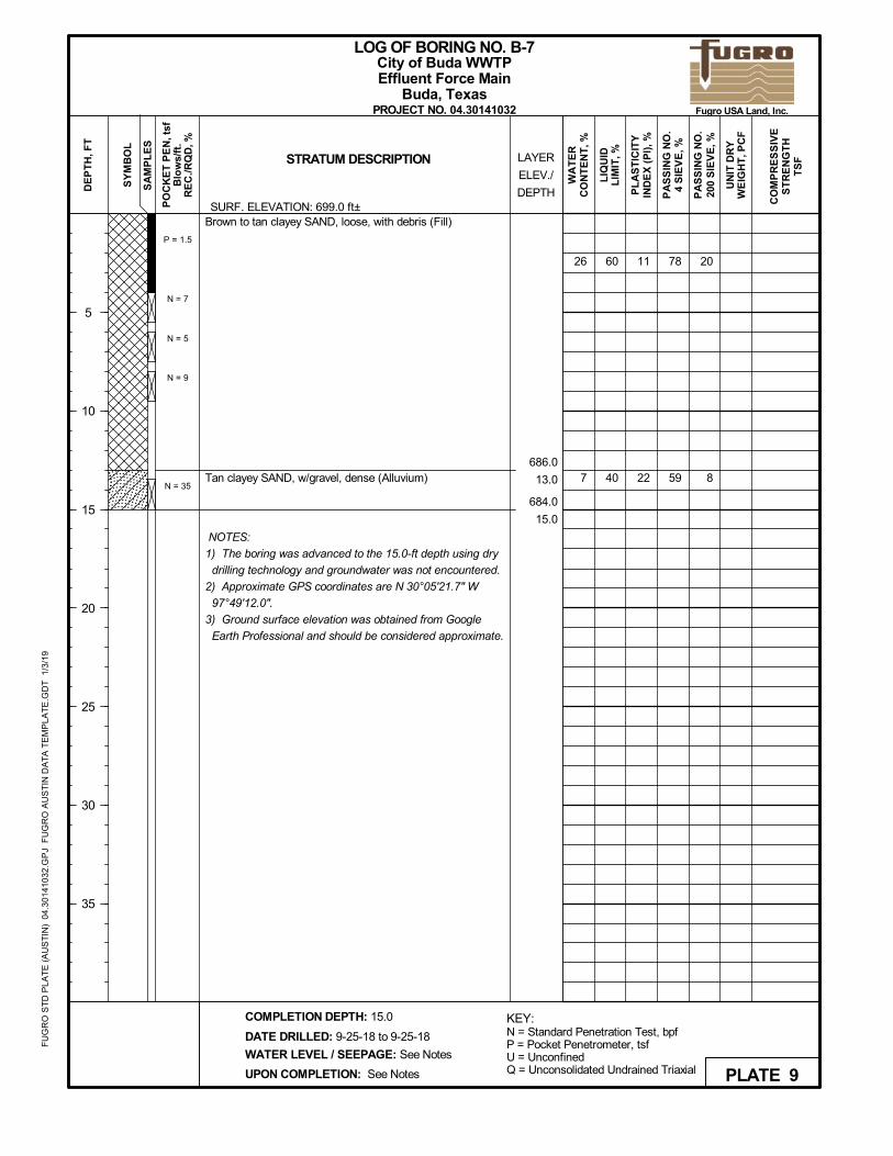
40686.0
13.0
684.0
15.0
Brown to tan clayey SAND, loose, with debris (Fill)
Tan clayey SAND, w/gravel, dense (Alluvium)
NOTES:
1) The boring was advanced to the 15.0-ft depth using dry
drilling technology and groundwater was not encountered.
2) Approximate GPS coordinates are N 30°05'21.7" W
97°49'12.0".
3) Ground surface elevation was obtained from Google
Earth Professional and should be considered approximate.
11
22
20
8
P = 1.5
N = 7
N = 5
N = 9
N = 35
26
7
UN
IT D
RY
WE
IGH
T, P
CF
PA
SS
ING
NO
.4
SIE
VE
, %
LIQ
UID
LIM
IT, %LAYER
ELEV./
DEPTH
SY
MB
OL
SA
MP
LE
SSTRATUM DESCRIPTION
DATE DRILLED: 9-25-18 to 9-25-18
PL
AS
TIC
ITY
IND
EX
(P
I), %
PA
SS
ING
NO
.20
0 S
IEV
E, %
PO
CK
ET
PE
N, t
sfB
low
s/ft
.R
EC
./RQ
D, %
WA
TE
RC
ON
TE
NT
, %
DE
PT
H, F
T
5
10
15
20
25
30
35
WATER LEVEL / SEEPAGE: See Notes
UPON COMPLETION: See Notes
COMPLETION DEPTH: 15.0
LOG OF BORING NO. B-7
PROJECT NO. 04.30141032
Effluent Force MainBuda, Texas
CO
MP
RE
SS
IVE
ST
RE
NG
TH
TS
F
KEY:N = Standard Penetration Test, bpfP = Pocket Penetrometer, tsfU = UnconfinedQ = Unconsolidated Undrained Triaxial PLATE 9
City of Buda WWTP
SURF. ELEVATION: 699.0 ft±
Fugro USA Land, Inc.
FU
GR
O S
TD
PL
AT
E (
AU
ST
IN)
04.
301
410
32.G
PJ
FU
GR
O A
US
TIN
DA
TA
TE
MP
LAT
E.G
DT
1/3
/19

85
100
58
46
37
691.0
6.0
673.5
23.5
672.0
25.0
Dark brown lean CLAY, w/sand, gravel and organics, very
stiff to hard. (Fill)
Reddish brown to tan clayey SAND, w/gravel and clay layers
and ferrous staining, loose to dense (Alluvium)
- clay layer at 13 feet
Light gray SHALE, highly weathered, moderately hard
(Eagle Ford)
NOTES:
1) The boring was advanced to the 25.0 ft depth using dry
drilling technology and groundwater was encountered at the
depth of 17.2 feet.
2) Approximate GPS coordinates are N 30° 5'27.49" W
97°49'6.41".
3) Ground surface elevation was obtained from Google Earth
Professional and should be considered approximate.
20
19
61
95
11
P = 4.5+
P = 4.5+
N = 15
N = 42
N = 39
N = 9
N = 47
N = 51
13
23
15
UN
IT D
RY
WE
IGH
T, P
CF
PA
SS
ING
NO
.4
SIE
VE
, %
LIQ
UID
LIM
IT, %LAYER
ELEV./
DEPTH
SY
MB
OL
SA
MP
LE
SSTRATUM DESCRIPTION
DATE DRILLED: 9-26-18 to 9-26-18
PL
AS
TIC
ITY
IND
EX
(P
I), %
PA
SS
ING
NO
.20
0 S
IEV
E, %
PO
CK
ET
PE
N, t
sfB
low
s/ft
.R
EC
./RQ
D, %
WA
TE
RC
ON
TE
NT
, %
DE
PT
H, F
T
5
10
15
20
25
30
35
WATER LEVEL / SEEPAGE: 18.0
UPON COMPLETION: 17.2
COMPLETION DEPTH: 25.0
LOG OF BORING NO. B-8
PROJECT NO. 04.30141032
Effluent Force MainBuda, Texas
CO
MP
RE
SS
IVE
ST
RE
NG
TH
TS
F
KEY:N = Standard Penetration Test, bpfP = Pocket Penetrometer, tsfU = UnconfinedQ = Unconsolidated Undrained Triaxial PLATE 10
City of Buda WWTP
SURF. ELEVATION: 697.0 ft±
Fugro USA Land, Inc.
FU
GR
O S
TD
PL
AT
E (
AU
ST
IN)
04.
301
410
32.G
PJ
FU
GR
O A
US
TIN
DA
TA
TE
MP
LAT
E.G
DT
1/3
/19
80
112
100
97
36
67
25
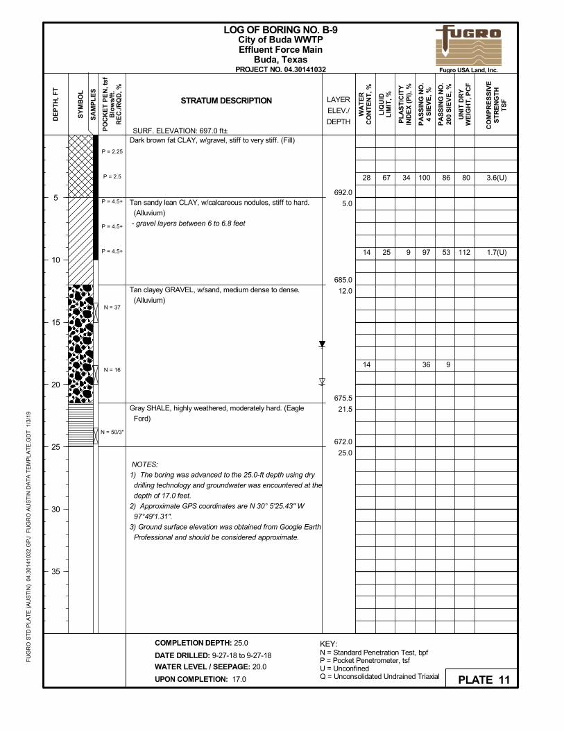
692.0
5.0
685.0
12.0
675.5
21.5
672.0
25.0
Dark brown fat CLAY, w/gravel, stiff to very stiff. (Fill)
Tan sandy lean CLAY, w/calcareous nodules, stiff to hard.
(Alluvium)
- gravel layers between 6 to 6.8 feet
Tan clayey GRAVEL, w/sand, medium dense to dense.
(Alluvium)
Gray SHALE, highly weathered, moderately hard. (Eagle
Ford)
NOTES:
1) The boring was advanced to the 25.0-ft depth using dry
drilling technology and groundwater was encountered at the
depth of 17.0 feet.
2) Approximate GPS coordinates are N 30° 5'25.43" W
97°49'1.31".
3) Ground surface elevation was obtained from Google Earth
Professional and should be considered approximate.
34
9
86
53
9
P = 2.25
P = 2.5
P = 4.5+
P = 4.5+
P = 4.5+
N = 37
N = 16
N = 50/3"
28
14
14
3.6(U)
1.7(U)
UN
IT D
RY
WE
IGH
T, P
CF
PA
SS
ING
NO
.4
SIE
VE
, %
LIQ
UID
LIM
IT, %LAYER
ELEV./
DEPTH
SY
MB
OL
SA
MP
LE
SSTRATUM DESCRIPTION
DATE DRILLED: 9-27-18 to 9-27-18
PL
AS
TIC
ITY
IND
EX
(P
I), %
PA
SS
ING
NO
.20
0 S
IEV
E, %
PO
CK
ET
PE
N, t
sfB
low
s/ft
.R
EC
./RQ
D, %
WA
TE
RC
ON
TE
NT
, %
DE
PT
H, F
T
5
10
15
20
25
30
35
WATER LEVEL / SEEPAGE: 20.0
UPON COMPLETION: 17.0
COMPLETION DEPTH: 25.0
LOG OF BORING NO. B-9
PROJECT NO. 04.30141032
Effluent Force MainBuda, Texas
CO
MP
RE
SS
IVE
ST
RE
NG
TH
TS
F
KEY:N = Standard Penetration Test, bpfP = Pocket Penetrometer, tsfU = UnconfinedQ = Unconsolidated Undrained Triaxial PLATE 11
City of Buda WWTP
SURF. ELEVATION: 697.0 ft±
Fugro USA Land, Inc.
FU
GR
O S
TD
PL
AT
E (
AU
ST
IN)
04.
301
410
32.G
PJ
FU
GR
O A
US
TIN
DA
TA
TE
MP
LAT
E.G
DT
1/3
/19
11669
66
82
29
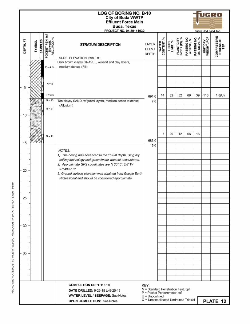
691.0
7.0
683.0
15.0
Dark brown clayey GRAVEL, w/sand and clay layers,
medium dense. (Fill)
Tan clayey SAND, w/gravel layers, medium dense to dense
(Alluvium)
NOTES:
1) The boring was advanced to the 15.0-ft depth using dry
drilling technology and groundwater was not encountered.
2) Approximate GPS coordinates are N 30° 5'18.8" W
97°48'57.0".
3) Ground surface elevation was obtained from Google Earth
Professional and should be considered approximate.
52
12
39
16
P = 4.5+
N = 8
P = 3.5
N = 43
N = 21
N = 41
14
7
1.8(U)
UN
IT D
RY
WE
IGH
T, P
CF
PA
SS
ING
NO
.4
SIE
VE
, %
LIQ
UID
LIM
IT, %LAYER
ELEV./
DEPTH
SY
MB
OL
SA
MP
LE
SSTRATUM DESCRIPTION
DATE DRILLED: 9-25-18 to 9-25-18
PL
AS
TIC
ITY
IND
EX
(P
I), %
PA
SS
ING
NO
.20
0 S
IEV
E, %
PO
CK
ET
PE
N, t
sfB
low
s/ft
.R
EC
./RQ
D, %
WA
TE
RC
ON
TE
NT
, %
DE
PT
H, F
T
5
10
15
20
25
30
35
WATER LEVEL / SEEPAGE: See Notes
UPON COMPLETION: See Notes
COMPLETION DEPTH: 15.0
LOG OF BORING NO. B-10
PROJECT NO. 04.30141032
Effluent Force MainBuda, Texas
CO
MP
RE
SS
IVE
ST
RE
NG
TH
TS
F
KEY:N = Standard Penetration Test, bpfP = Pocket Penetrometer, tsfU = UnconfinedQ = Unconsolidated Undrained Triaxial PLATE 12
City of Buda WWTP
SURF. ELEVATION: 698.0 ft±
Fugro USA Land, Inc.
FU
GR
O S
TD
PL
AT
E (
AU
ST
IN)
04.
301
410
32.G
PJ
FU
GR
O A
US
TIN
DA
TA
TE
MP
LAT
E.G
DT
1/3
/19
128
101
87
62
60
83
79
692.0
4.0
686.0
10.0
681.0
15.0
Tan to brown sandy fat CLAY, w/gravel, stiff to very stiff.
(Fill)
Dark brown clayey GRAVEL, w/sand and ferrous stainings,
loose to medium dense (Fill)
Tan to light gray shaly CLAY, very stiff to hard. (Taylor)
NOTES:
1) The boring was advanced to the 15.0-ft depth using dry
drilling technology and groundwater was not encountered.
2) Approximate GPS coordinates are N 30° 5'19.6" W
97°48'40.8".
3) Ground surface elevation was obtained from Google Earth
Professional and should be considered approximate.
37
39
54
53
27
P = 3.5
N = 14
N = 6
P = 1.5
P = 3.0
P = 4.5+
25
12
25
2.1(U)
2.5(U)
UN
IT D
RY
WE
IGH
T, P
CF
PA
SS
ING
NO
.4
SIE
VE
, %
LIQ
UID
LIM
IT, %LAYER
ELEV./
DEPTH
SY
MB
OL
SA
MP
LE
SSTRATUM DESCRIPTION
DATE DRILLED: 9-25-18 to 9-25-18
PL
AS
TIC
ITY
IND
EX
(P
I), %
PA
SS
ING
NO
.20
0 S
IEV
E, %
PO
CK
ET
PE
N, t
sfB
low
s/ft
.R
EC
./RQ
D, %
WA
TE
RC
ON
TE
NT
, %
DE
PT
H, F
T
5
10
15
20
25
30
35
WATER LEVEL / SEEPAGE: See Notes
UPON COMPLETION: See Notes
COMPLETION DEPTH: 15.0
LOG OF BORING NO. B-11
PROJECT NO. 04.30141032
Effluent Force MainBuda, Texas
CO
MP
RE
SS
IVE
ST
RE
NG
TH
TS
F
KEY:N = Standard Penetration Test, bpfP = Pocket Penetrometer, tsfU = UnconfinedQ = Unconsolidated Undrained Triaxial PLATE 13
City of Buda WWTP
SURF. ELEVATION: 696.0 ft±
Fugro USA Land, Inc.
FU
GR
O S
TD
PL
AT
E (
AU
ST
IN)
04.
301
410
32.G
PJ
FU
GR
O A
US
TIN
DA
TA
TE
MP
LAT
E.G
DT
1/3
/19
104
109
110
100
99
100
83
50
49
697.0
8.0
690.0
15.0
Brown to dark brown fat CLAY, w/sand, calcerous nodules
and ferrous stainings, stiff to hard. (Residual Soil)
Tan fat CLAY, w/sand, shaly, very stiff to hard. (Taylor)
NOTES:
1) The boring was advanced to the 15.0-ft depth using dry
drilling technology and groundwater was not encountered.
2) Approximate GPS coordinates are N 30° 5'19.6" W
97°48'23.8".
3) Ground surface elevation was obtained from Google Earth
Professional and should be considered approximate.
59
29
31
83
83
91
P = 1.5
P = 4.0
P = 4.5+
P = 4.5+
P = 4.5+
P = 4.0
21
20
20
9.0(U)
4.8(U)
2.6(U)
UN
IT D
RY
WE
IGH
T, P
CF
PA
SS
ING
NO
.4
SIE
VE
, %
LIQ
UID
LIM
IT, %LAYER
ELEV./
DEPTH
SY
MB
OL
SA
MP
LE
SSTRATUM DESCRIPTION
DATE DRILLED: 9-25-18 to 9-25-18
PL
AS
TIC
ITY
IND
EX
(P
I), %
PA
SS
ING
NO
.20
0 S
IEV
E, %
PO
CK
ET
PE
N, t
sfB
low
s/ft
.R
EC
./RQ
D, %
WA
TE
RC
ON
TE
NT
, %
DE
PT
H, F
T
5
10
15
20
25
30
35
WATER LEVEL / SEEPAGE: See Notes
UPON COMPLETION: See Notes
COMPLETION DEPTH: 15.0
LOG OF BORING NO. B-12
PROJECT NO. 04.30141032
Effluent Force MainBuda, Texas
CO
MP
RE
SS
IVE
ST
RE
NG
TH
TS
F
KEY:N = Standard Penetration Test, bpfP = Pocket Penetrometer, tsfU = UnconfinedQ = Unconsolidated Undrained Triaxial PLATE 14
City of Buda WWTP
SURF. ELEVATION: 705.0 ft±
Fugro USA Land, Inc.
FU
GR
O S
TD
PL
AT
E (
AU
ST
IN)
04.
301
410
32.G
PJ
FU
GR
O A
US
TIN
DA
TA
TE
MP
LAT
E.G
DT
1/3
/19
121
119
105
100
91
49
50
48
749.0
15.0
Tan to light gray lean CLAY, w/ferrous stainings and calcium
deposits. shaly, hard. (Taylor)
NOTES:
1) The boring was advanced to the 15.0-ft depth using dry
drilling technology and groundwater was not encountered.
2) Approximate GPS coordinates are N 30° 5'14.9" W
97°48'5.4".
3) Ground surface elevation was obtained from Google Earth
Professional and should be considered approximate.
32
31
29
90
77
P = 4.0
P = 4.5+
P = 4.5+
P = 4.5+
P = 4.5+
P = 4.5+
13
13
22
5.4(U)
4.1(U)
3.5(U)
UN
IT D
RY
WE
IGH
T, P
CF
PA
SS
ING
NO
.4
SIE
VE
, %
LIQ
UID
LIM
IT, %LAYER
ELEV./
DEPTH
SY
MB
OL
SA
MP
LE
SSTRATUM DESCRIPTION
DATE DRILLED: 9-25-18 to 9-25-18
PL
AS
TIC
ITY
IND
EX
(P
I), %
PA
SS
ING
NO
.20
0 S
IEV
E, %
PO
CK
ET
PE
N, t
sfB
low
s/ft
.R
EC
./RQ
D, %
WA
TE
RC
ON
TE
NT
, %
DE
PT
H, F
T
5
10
15
20
25
30
35
WATER LEVEL / SEEPAGE: See Notes
UPON COMPLETION: See Notes
COMPLETION DEPTH: 15.0
LOG OF BORING NO. B-13
PROJECT NO. 04.30141032
Effluent Force MainBuda, Texas
CO
MP
RE
SS
IVE
ST
RE
NG
TH
TS
F
KEY:N = Standard Penetration Test, bpfP = Pocket Penetrometer, tsfU = UnconfinedQ = Unconsolidated Undrained Triaxial PLATE 15
City of Buda WWTP
SURF. ELEVATION: 764.0 ft±
Fugro USA Land, Inc.
FU
GR
O S
TD
PL
AT
E (
AU
ST
IN)
04.
301
410
32.G
PJ
FU
GR
O A
US
TIN
DA
TA
TE
MP
LAT
E.G
DT
1/3
/19
Lensed
DENSITY OF GRANULAR SOILS
Very Dense
Dense
4
CLAY
Blocky
material or color with layers
1.00 to 2.00
COARSE
0.074
Layer
With
<5% of sample.
or glossy, sometimes striated.
COMPRESSIVE STRENGTH
Dry
to fracturing.
Laminatedplastic limit and less than liquid limit
15% to 29% of sample.15 to 25% of sample.
(2)
(1)
Fugro Consultants, Inc. 1) ASTM D 2488
(2)
Well-Graded
CLAYEY GRAVEL (GC)
0.002
Hard
layers less than 6 mm thick.
Loose
Very Loose
30-50
Slickensided
Tons Per Sq. Ft.
3"
2.00
Poorly-GradedWell-Graded
sampleInclusion 1/8" to 3" thick extendingthrough sample.Inclusion >3" thick extending through
Trace
3/4"
76.2 19.1
MEDIUM
SAND
10-30
fracture with little resistance
MOISTURE
than liquid limit.
Soft
Inclusions of small pockets of
CLAYEY SAND (SC)
down into small angular lumps
SOIL GRAIN SIZE IN MILIMETERS
procedures. The stratum lines on the logs may be transitional and approximate in nature. Water level
GRAVEL (GP)
FINE
200
Cohesive soil that can be broken
0.5 to 1.00
COARSE
STRENGTH OF COHESIVE SOILS
RELATIVEDENSITY
10
0.420
GRAVEL
which resist further breakdown.
Very Moist
5% to 10% of sample.
12"
No water evident in sample; fines less
Less Than 0.25
Alternating layers of varying
DESCRIPTION
UNDRAINED
than plastic limit.
SILT
at least 6 mm thick.
CONSISTENCY
Stratified
Sample feels damp; fines near the plasticlimitWater visible on sample; fines greater
material or color with the
304
Very Soft
NUMBER OF BLOWS
Breaks along definite planes of
CRITERIA
DESCRIPTIVE TERMS FOR SOIL
Firm
Fracture planes appear polishedParting
Seam
FINE
Medium
different soils.
40
Stiff
0-4
sample.
4-10
2.00 to 4.00
INCLUSIONS
Moist
4.76
Fissured
Alternating layers of varying
Wet
Poorly-Graded SILTY SAND (SM)
Few
greater than 4.00
0.25 to 0.50
Very Stiff
Inclusion <1/8" thick extending through
Over 50
SILTY GRAVEL (GM)
PER FT., N
REFERENCES:
TERMS AND SYMBOLS USED ON BORING LOGS FOR SOIL
(1)
Little
COBBLES
2) Peck, Hanson and Thornburn, (1974),
U.S.STANDARD SIEVE
Sample bears free water; fines greater
measurements refer only to those observed at the times and places indicated, and may vary with time, geologic
BOULDERS
NOTE: Information on each boring log is a compilation of subsurface conditions and soil and rock classifications obtained
SOIL GRAIN SIZE
SOIL TYPES
from the field as well as from laboratory testing of samples. Strata have been interpreted from commonly accepted
Foundation Engineering.
condition or construction activity.
LEAN CLAY (CL) FILL
SAND (SP)
GRAVEL (GW)
FAT CLAY (CH) SILT (ML)
SAND (SW)
PLATE 16
SHALE
2nd Edition,revised June,1974.Foundation Exploration & Design Manual,
SANDSTONE
2) The Bridge Division, Texas Highway Dept.
1) British Standard(1981)
LIMESTONE
0.08"-1/2"Thinly-Laminated
LIMESTONE
(1)
Fugro Consultants, Inc.
obtained from the field as well as from laboratory testing of samples. Strata have been interpreted by commonly
Cavernous
Vesicular
Shallow
SURFACES
35-65Smooth
Porous
material is decomposed or
Sample
converted to soil.TheAll rock material is
Void
Close
Very Close
and discontinuity surfaces.
condition or construction activity.
Information on each boring log is a compilation of subsurface conditions and soil and rock classificaitons
Vertical
MARL
BS 5930.
HIGHLY WEATHERED
NOTE:
JOINT DESCRIPTION
measurements refer only to those observed at the times and places indicated, and may vary with time, geologic
(2)
WEATHEREDSHALE
Code of Practice for Site Investigation
Residual Soil
cavities, formed by expansion of gas
Penetration
composition from that of the
bubbles or steam during solidificationdecomposed and/or
ModeratelySmall solutional concavities.
Containing small cavities, usually
SAMPLER TYPES
DOLOMITIC LIMESTONEDOLOMITIC
HIGHLY WEATHERED
Less than half of the rock
weathering of rock material
of the rock.
Containing cavities or caverns,
Thin-
REFERENCES:
Planar
Standard
0-5
Can be carved with a knife
85-90
sometimes quite large. Most frequent
walled
fabric are destroyed.
SPACING
>3'
Horizontal
Wide 65-85
lined with a mineral of different
WEATHERING GRADES OF ROCKMASS
Slightly
Core
Cavities
Very Hard
Medium Close
HARDNESS
Interstice; a general term for pore
mass structure and material
disintegrated to a soil.
original mass structure is
Auger
Tube
INCLINATION
2"-12"
2"-2'
accepted procedures. The stratum lines on the logs may be transitional and approximate in nature. Water level
TERMS AND SYMBOLS USED ON BORING LOGS FOR ROCK
LIMESTONE SANDSTONE
All rock material is
Can be scratched easily with a knife
in limestones and dolomites.
space or other openings in rock.
Laminated
5-35
Cannot be scratched with a knife
Steep
Vuggy
Thick
Highly
SOLUTION & VOID CONDITIONS
disintegrated to soil.The
Rock
still largely intact.
Completely
Containing pore, interstices, or
Irregular
>4'
1/2"-2"
TestPenetration
Low Hardness
Moderate
Thin
material is decomposed orMore than half of the rock
disintegrated to a soil.
ROCK TYPES
<0.08"
Polished, grooved
Discoloration indicates
Crumbles under hand pressure
Jagged or pitted
Containing numerous small, unlined
other openings which may or may not
Moderately Hard
BagTHD Cone
2'-4'Friable
12"-3'
BEDDING THICKNESS
Test
Slickensided
Very Thin
Undulating or granular
<2"
Rough
Very Thick
surrounding rock.
interconnect.
Sample
HIGHLY WEATHERED
PLATE 17


