
© Copyright Reserved Autonics Co., Ltd. iii
GP-GM6 CPU (RS232)
Technical Support Manual

Preface
ii © Copyright Reserved Autonics Co., Ltd.
Preface
© Copyright Reserved Autonics Co., Ltd. 3
Preface
Thank you very much for selecting Autonics products.
Please familiarize yourself with the information contained in the Safety Precautions section before using this product.
This user manual contains information about the product and its proper use, and should be kept in a place where it will be easy to access.
Technical Support Manual Guide
4 © Copyright Reserved Autonics Co., Ltd.
Technical Support Manual Guide
Please familiarize yourself with the information in this manual before using the product.
This manual provides detailed information on the product's features. It does not offer any guarantee concerning matters beyond the scope of this manual.
This manual may not be edited or reproduced in either part or whole without permission.
This manual is not provided as part of the product package. Please visit our home-page (www.autonics.com) to download a copy.
The manual's content may vary depending on changes to the product's software and other unforeseen developments within Autonics, and is subject to change without prior notice. Upgrade notice is provided through our homepage.
We contrived to describe this manual more easily and correctly. However, if there are any corrections or questions, please notify us these on our homepage.
Technical Support Manual Symbols
© Copyright Reserved Autonics Co., Ltd. 5
Technical Support Manual Symbols
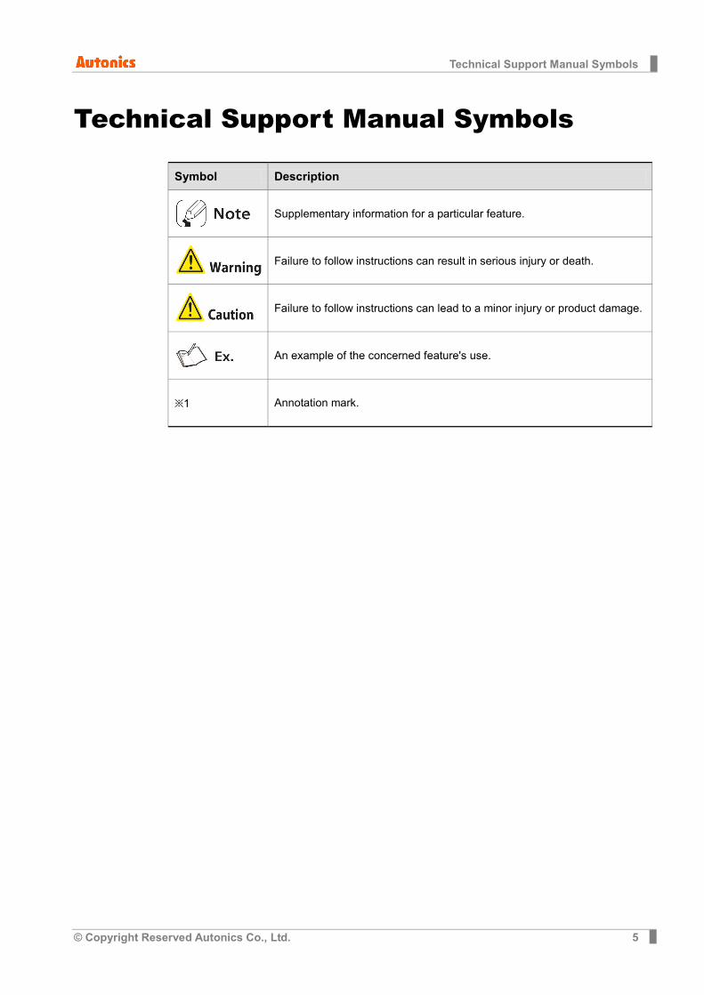
Symbol Description
Supplementary information for a particular feature.
Failure to follow instructions can result in serious injury or death.
Failure to follow instructions can lead to a minor injury or product damage.
An example of the concerned feature's use.
※1 Annotation mark.

Safety Precautions
6 © Copyright Reserved Autonics Co., Ltd.
Safety Precautions
Following these safety precautions will ensure the safe and proper use of the product and help prevent accidents, as well as minimizing possible hazards.
Safety precautions are categorized as Warnings and Cautions, as defined below:
Warning Failure to follow the instructions may lead to a serious injury
or accident.
Caution Failure to follow the instructions may lead to a minor injury or
accident.
Fail-safe device must be installed when using the unit with machinery that may cause
serious injury or substantial economic loss. (e.g. nuclear power control, medical equipment, ships, vehicles, railways, aircraft, combustion apparatus, safety equipment, crime/disaster prevention devices, etc.) Failure to follow this instruction may result in personal injury, fire, or economic loss.
In case using the Graphic Panel touch switch for controlling, do not use the switch as an emergency switches or those related to safety that may cause physical injury or property damage in the event of a malfunction. Failure to follow this instruction may result in personal injury, fire, or economic loss.
In case controlling other devices through Graphic Panel communication, and there is a possibility of malfunction due to communication error, an alternative circuit must be constructed. Failure to follow this instruction may result in personal injury, fire, or economic loss.
Do not use the product in an area or an environment not specified in the manual. Failure to follow this instruction may result in personal injury, fire, or economic loss.
Do not connect, repair, or inspect the unit while connected to a power source. Failure to follow this instruction may result in electric shock or fire.
Do not disassemble or modify the unit. Please contact us if necessary. Failure to follow this instruction may result in electric shock or fire.
Use the insulated trans to supply the rectified power. Failure to follow this instruction may result in electric shock or fire.
Do not use over the rated power. Failure to follow this instruction may result in electric shock or fire.
This product uses lithium battery, do not disassemble or burn up. Failure to follow this instruction may result in explosion or fire.
Wire properly after checking power terminal polarity. Failure to follow this instruction may result in fire or product malfunction
Safety Precautions
© Copyright Reserved Autonics Co., Ltd. 7
Please read all notes and cautions related to installation and wiring in the manual.
Failure to follow this instruction may result in electric shock or product malfunction.
Make sure the ground wire of Graphic Panel is wired separately from the ground wires of other devices. Ground resistance must be less than 100Ω, and a lead wire of which sectional area is over 1.25mm2 should be used. Failure to follow this instruction may result in electric shock or product malfunction.
When connecting Graphic Panel ports and constructing input/output, check the pin number and terminal block before connecting. Failure to follow this instruction may result in fire or product malfunction.
Tighten bolt on terminal block with specified tightening torque. Failure to follow this instruction may result in short circuit, fire or product malfunction.
Do not press the surface of the touch panel with sharp or hard objects. Failure to follow this instruction may result in touch panel damage.
Keep Graphic Panel at the specified temperature. Failure to follow this instruction may result in LCD panel damage due to over the rated temperature range.
Do not inflow dust or wire dregs into the unit. Failure to follow this instruction may result in fire or product malfunction.
Do not use in an area with excessive humidity or temperature. Failure to follow this instruction may result in product damage or shortening the life cycle of the unit.
Do not close ventilating opening of this product. Failure to follow this instruction may result in product damage due to increase inner heat.
Keep the product out of direct sunlight or excessive dust. Failure to follow this instruction may result in product damage or shortening the life cycle of the unit.
Do not use or store in a place with shock or vibration. Failure to follow this instruction may result in product damage or shortening the life cycle of the unit.
When liquid crystal from the broken LCD is smeared with skin, wash it for 15 minutes. If it is gotten in the eye, wash it for 15 minutes and contact with the medical specialist for more information.
Do not use water or oil-based detergent when cleaning the unit. Use dry cloth to clean the unit. Failure to follow this instruction may result in electric shock or fire.
Please separate as an industrial waste when disuse this unit.
To change the battery, contact the store or an authorized technician.
The manufacturer is not liable for damages that occur due to causes for which the manufacturer is not responsible, damages that occur due to an extraordinary situation, secondary damages, compensation for accidents, damages occurring on other products, compensation for other processes, and damage and loss of opportunity to the user due a malfunction of the product, regardless of the predictability of the accident.

Safety Precautions
8 © Copyright Reserved Autonics Co., Ltd.
Note that this device is KCC certified for commercial use. Make proper applications for the product.
Table of Contents
© Copyright Reserved Autonics Co., Ltd. 9
Table of Contents
Preface ............................................................................................................................. 3
Technical Support Manual Guide ..................................................................................... 4
Technical Support Manual Symbols ................................................................................. 5
Safety Precautions ........................................................................................................... 6
Table of Contents ............................................................................................................. 9
1 System ....................................................................................................... 11
1.1 Version ............................................................................................................... 11
1.2 Connections ....................................................................................................... 11
1.3 Communication cable connection and dimensions (communication cable model: C3M5P01-D9F0-D9M0) .................................. 11
2 GP-S070 Communication Setting ............................................................ 13
2.1 GP Editor Setting ............................................................................................... 13
2.2 GP-S070 Setting ................................................................................................ 15
2.3 GMWIN Setting .................................................................................................. 17
2.4 Device conversion (GP/LP <-> GMWIN) ........................................................... 20
3 Examples ................................................................................................... 21
3.1 GP-S070 Drawing .............................................................................................. 21
3.2 PLC Program ..................................................................................................... 21
3.3 GP-S070 – PLC device connection ................................................................... 22
3.4 GP Editor Drawing ............................................................................................. 23
3.4.1 Numeral display.......................................................................................... 23 3.4.2 Numeral input ............................................................................................. 24 3.4.3 Touch key (Up key) .................................................................................... 25 3.4.4 Touch key (Down key) ................................................................................ 26 3.4.5 Lamp .......................................................................................................... 27 3.4.6 Touch key (Reset key) ................................................................................ 28
4 Appendix .................................................................................................... 29
4.1 Serial setting ...................................................................................................... 29

Table of Contents
10 © Copyright Reserved Autonics Co., Ltd.

1 System
© Copyright Reserved Autonics Co., Ltd. 11
1 System
1.1 Version Software Version Note
GP Editor V4.01 (build 023) —
GP-S070 Firmware V1.20 Release : 2016.01.26
Ms Windows Windows 7 —
GMWIN V 4.18 —
1.2 Connections
GP-S070-T9D6 CPU : GM6-CPUA
1.3 Communication cable connection and dimensions (communication cable model: C3M5P01-D9F0-D9M0)

1 System
12 © Copyright Reserved Autonics Co., Ltd.

2 GP-S070 Communication Setting
© Copyright Reserved Autonics Co., Ltd. 13
2 GP-S070 Communication Setting
2.1 GP Editor Setting 1st Select [Project] – [New] on menu.
If you have the saved file, open the project at [Load].
2nd At GP/PLC Type dialog box, set GP/LP Type and CH1/2 Group/Type. Item Setting
GP / LP Type GP-S070 T9D6
CH1 Group / Type LS GLOFA GM SERIES / GM6_Tool
CH2 Group / Type No Use
2 GP-S070 Communication Setting
14 © Copyright Reserved Autonics Co., Ltd.
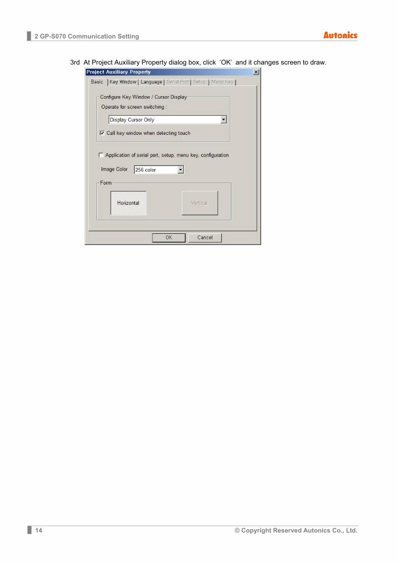
3rd At Project Auxiliary Property dialog box, click ‘OK’ and it changes screen to draw.

2 GP-S070 Communication Setting
© Copyright Reserved Autonics Co., Ltd. 15
2.2 GP-S070 Setting 1st Touch top-left of the GP.
2nd Touch ‘Environment’.
3rd Touch ‘Serial Communication’.

2 GP-S070 Communication Setting
16 © Copyright Reserved Autonics Co., Ltd.
4th At serial communication, set as below.
PROTOCOL PORT CH1 GM6_Tool V1.5M RS-232C SET
CH2 No Use RS-422 SET
5th Touch right ‘SET’ and set as below.
Item Setting Note
Baud rate 38400 Fixed Flow control XON/XOFF Don’t care Parity bit NONE Fixed
Data bit 8-bit Fixed
Stop bit 1-bit Fixed
2 GP-S070 Communication Setting
© Copyright Reserved Autonics Co., Ltd. 17
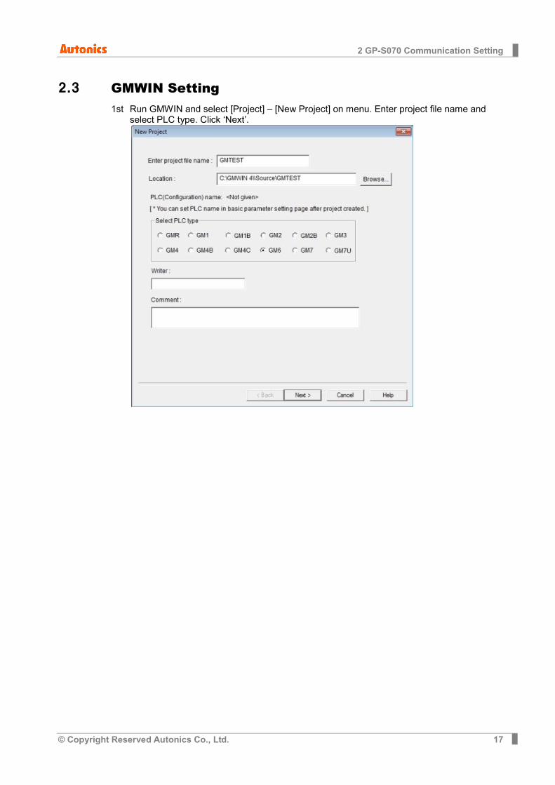
2.3 GMWIN Setting 1st Run GMWIN and select [Project] – [New Project] on menu. Enter project file name and
select PLC type. Click ‘Next’.

2 GP-S070 Communication Setting
18 © Copyright Reserved Autonics Co., Ltd.
2nd Check program file name and instance name. Click ‘Next’. Select program language as LD and click ‘Finish’.
2 GP-S070 Communication Setting
© Copyright Reserved Autonics Co., Ltd. 19
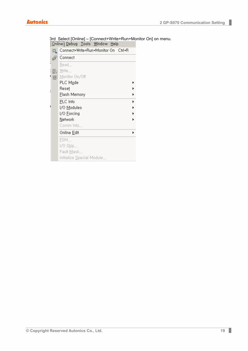
3rd Select [Online] – [Connect+Write+Run+Monitor On] on menu.
2 GP-S070 Communication Setting
20 © Copyright Reserved Autonics Co., Ltd.
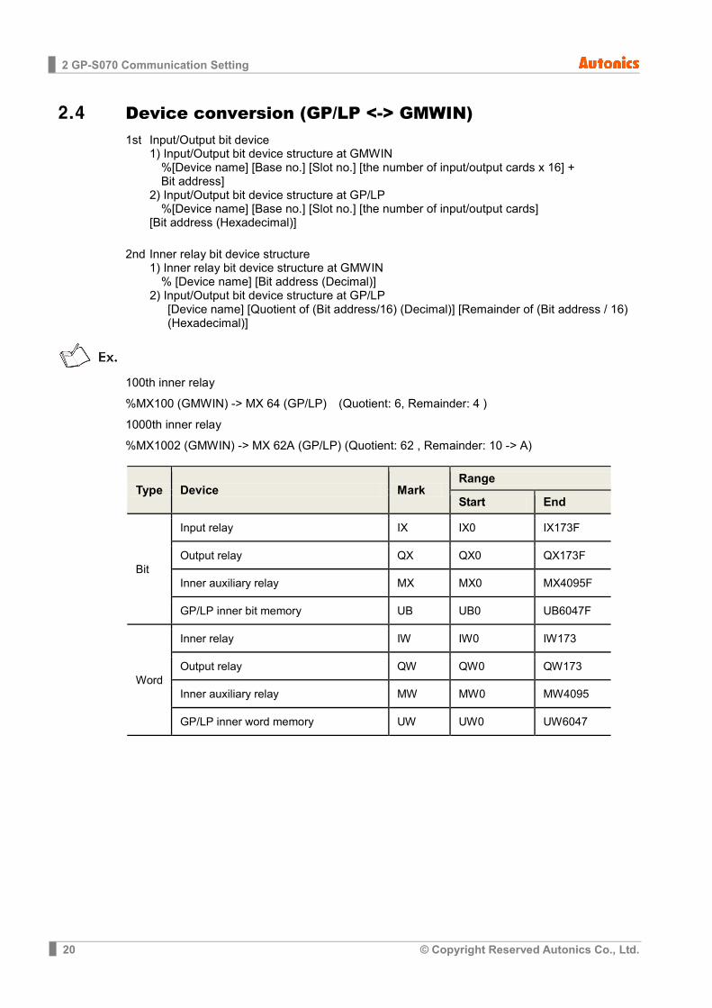
2.4 Device conversion (GP/LP <-> GMWIN) 1st Input/Output bit device
1) Input/Output bit device structure at GMWIN %[Device name] [Base no.] [Slot no.] [the number of input/output cards x 16] + Bit address]
2) Input/Output bit device structure at GP/LP %[Device name] [Base no.] [Slot no.] [the number of input/output cards]
[Bit address (Hexadecimal)]
2nd Inner relay bit device structure 1) Inner relay bit device structure at GMWIN
% [Device name] [Bit address (Decimal)] 2) Input/Output bit device structure at GP/LP [Device name] [Quotient of (Bit address/16) (Decimal)] [Remainder of (Bit address / 16)
(Hexadecimal)]
100th inner relay
%MX100 (GMWIN) -> MX 64 (GP/LP) (Quotient: 6, Remainder: 4 )
1000th inner relay
%MX1002 (GMWIN) -> MX 62A (GP/LP) (Quotient: 62 , Remainder: 10 -> A)
Type Device Mark Range
Start End
Bit
Input relay IX IX0 IX173F
Output relay QX QX0 QX173F
Inner auxiliary relay MX MX0 MX4095F
GP/LP inner bit memory UB UB0 UB6047F
Word
Inner relay IW IW0 IW173
Output relay QW QW0 QW173
Inner auxiliary relay MW MW0 MW4095
GP/LP inner word memory UW UW0 UW6047

3 Examples
© Copyright Reserved Autonics Co., Ltd. 21
3 Examples
3.1 GP-S070 Drawing
3.2 PLC Program
Input Instruction function Output
Instruction Description Device
Instruction Description Device
CU Up counter pulse input MX1 QU Up counter
contact output MW5
CD Down counter pulse input MX2 QD Down counter
contact output -
R Reset signal input MX3 CV Counter PV
output QW0
LD SV input MX4
PV SV MW8
3 Examples
22 © Copyright Reserved Autonics Co., Ltd.
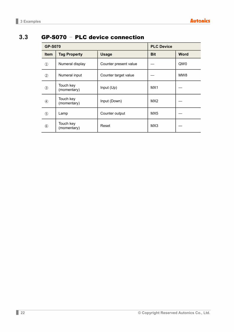
3.3 GP-S070 – PLC device connection GP-S070 PLC Device Item Tag Property Usage Bit Word ① Numeral display Counter present value — QW0 ② Numeral input Counter target value — MW8
③ Touch key (momentary) Input (Up) MX1 —
④ Touch key (momentary) Input (Down) MX2 —
⑤ Lamp Counter output MX5 —
⑥ Touch key (momentary) Reset MX3 —
3 Examples
© Copyright Reserved Autonics Co., Ltd. 23
3.4 GP Editor Drawing
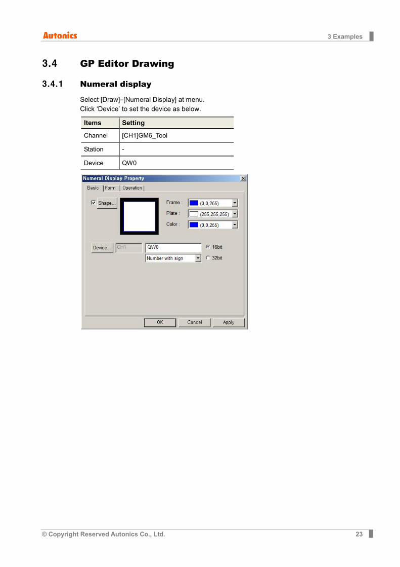
3.4.1 Numeral display
Select [Draw]–[Numeral Display] at menu. Click ‘Device’ to set the device as below.
Items Setting
Channel [CH1]GM6_Tool
Station -
Device QW0

3 Examples
24 © Copyright Reserved Autonics Co., Ltd.
3.4.2 Numeral input
Select [Draw]–[Numeral Input] at menu. Click ‘Device’ to set the device as below.
Items Setting
Channel [CH1]GM6_Tool
Station -
Device MW8

3 Examples
© Copyright Reserved Autonics Co., Ltd. 25
3.4.3 Touch key (Up key)
Select [Draw]–[Touch Key]–[Action]–[Bit]. Click ‘Device’ to set the device as below.
Items Setting
Channel [CH1]GM6_Tool Station -
Device MX1
Action Momentary
3 Examples
26 © Copyright Reserved Autonics Co., Ltd.
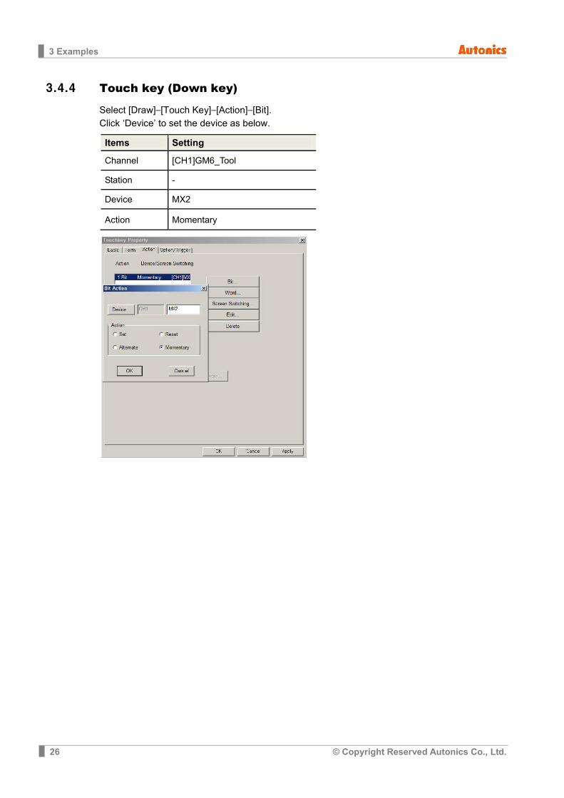
3.4.4 Touch key (Down key)
Select [Draw]–[Touch Key]–[Action]–[Bit]. Click ‘Device’ to set the device as below.
Items Setting
Channel [CH1]GM6_Tool Station -
Device MX2
Action Momentary

3 Examples
© Copyright Reserved Autonics Co., Ltd. 27
3.4.5 Lamp Select [Draw]-[Lamp]. Click ‘Device’ to set the device as below.
Item Setting
Channel [CH1]GM6_Tool
Station -
Device MX5

3 Examples
28 © Copyright Reserved Autonics Co., Ltd.
3.4.6 Touch key (Reset key)
Select [Draw]–[Touch Key]–[Action]–[Bit]. Click ‘Device’ to set the device as below.
Item Setting
Channel [CH1]GM6_Tool
Station -
Device MX3
Action Momentary

4 Appendix
© Copyright Reserved Autonics Co., Ltd. 29
4 Appendix
4.1 Serial setting Serial port setting are available at GP-S070 and GP Editor.
GP Editor is available only for CH1 serial port setting.
Item Setting at GP Editor Setting at GP-S070
CH1 comm. setting Avaliable Avaliable
CH2 comm. setting Unavailable Avaliable
1st Check the settings; Application of serial port, setup, menu key, configuration at [Common]-[Auxiliary Configuration]-[Project].
4 Appendix
30 © Copyright Reserved Autonics Co., Ltd.
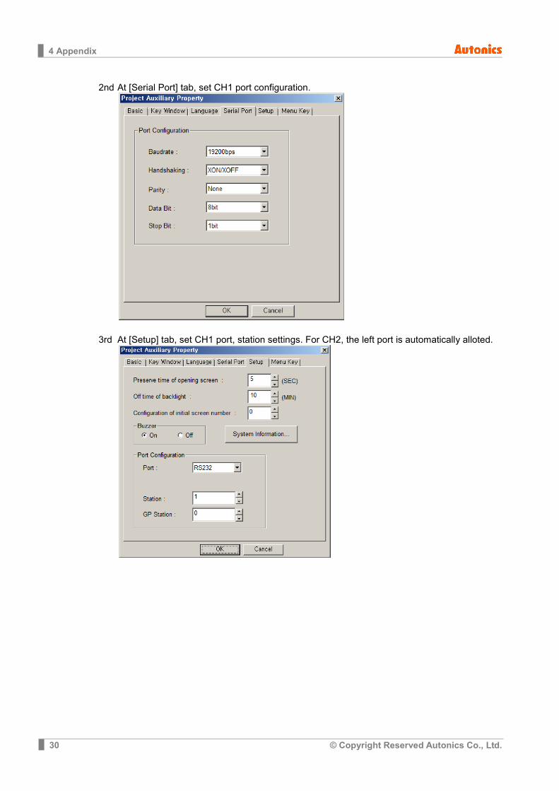
2nd At [Serial Port] tab, set CH1 port configuration.
3rd At [Setup] tab, set CH1 port, station settings. For CH2, the left port is automatically alloted.

4 Appendix
© Copyright Reserved Autonics Co., Ltd. 31

4 Appendix
32 © Copyright Reserved Autonics Co., Ltd.


