
2
GraphiteVPX/GbE 20-Port Managed Carrier Ethernet Switch
Connect Tech Inc. Tel: 519-836-1291
42 Arrow Road Toll: 800-426-8979 (North America only) Guelph, Ontario Fax: 519-836-4878 N1K 1S6 Email: [email protected] www.connecttech.com [email protected] CTIM-00461 Revision 0.02 2016/10/27

GraphiteVPX/GbE 16+4-Port - Managed Carrier Ethernet Switch
Users Guide
www.connecttech.com
Document: CTIM-00461 Revision: 0.02
Page 2 of 26
Connect Tech Inc. 800-426-8979 | 519-836-1291
Date: 2016/10/27
Table of Contents
Table of Contents ................................................................................................................................... 2
Preface ................................................................................................................................................... 3
Disclaimer ....................................................................................................................................................... 3 Customer Support Overview ........................................................................................................................... 3 Contact Information ........................................................................................................................................ 3 Limited Product Warranty ............................................................................................................................... 4 Copyright Notice ............................................................................................................................................. 4 Trademark Acknowledgment .......................................................................................................................... 4 ESD Warning .................................................................................................................................................. 5
Revision History .................................................................................................................................... 5
Introduction........................................................................................................................................... 6
Product Overview .................................................................................................................................. 8
Block Diagram ................................................................................................................................................ 8 Ordering Part Numbers ................................................................................................................................... 9 Connector Locations (VPG201) .................................................................................................................... 10 Connector Summary ...................................................................................................................................... 11
VPG20x - Detailed Feature Pinouts ...................................................................................................... 12
CLI Management Interface .................................................................................................................. 13
CLI Access via the RS232 Serial Port ........................................................................................................... 13 CLI Basics ..................................................................................................................................................... 14 Complete CLI and Protocol Configuration Reference Guide ........................................................................ 14
Web Management Interface ................................................................................................................. 15
Accessing the Web Management Interface ................................................................................................... 15 Web Management Interface Overview .......................................................................................................... 16 Complete Web Protocol Configuration Reference Guide ............................................................................. 16
Port LED Details ................................................................................................................................. 17
System Management Interface ............................................................................................................. 18
Addressing the I2C Slave Interface (I2C Mux) ............................................................................................. 18 Writing to the I2C Slave Interface................................................................................................................. 19 Reading from the I2C devices ....................................................................................................................... 19
Thermal Details ................................................................................................................................... 20
Thermal Parameters ....................................................................................................................................... 20
Mechanical Details ............................................................................................................................... 21
3D STEP Models ........................................................................................................................................... 21 VPG202 Top Side View ................................................................................................................................ 22 VPG202 – Bottom Side View ....................................................................................................................... 23
RTM Details ........................................................................................................................................ 24
RTG002 – Pinout Information ...................................................................................................................... 25 RTG002 – Top Side View ............................................................................................................................. 26 RTG002 – Bottom Side View ....................................................................................................................... 26

GraphiteVPX/GbE 16+4-Port - Managed Carrier Ethernet Switch
Users Guide
www.connecttech.com
Document: CTIM-00461 Revision: 0.02
Page 3 of 26
Connect Tech Inc. 800-426-8979 | 519-836-1291
Date: 2016/10/27
Preface
Disclaimer The information contained within this user’s guide, including but not limited to any product specification, is
subject to change without notice.
Connect Tech assumes no liability for any damages incurred directly or indirectly from any technical or
typographical errors or omissions contained herein or for discrepancies between the product and the user’s
guide.
Customer Support Overview If you experience difficulties after reading the manual and/or using the product, contact the Connect Tech
reseller from which you purchased the product. In most cases the reseller can help you with product installation
and difficulties.
In the event that the reseller is unable to resolve your problem, our highly qualified support staff can assist you.
Our support section is available 24 hours a day, 7 days a week on our website at:
www.connecttech.com/sub/support/support.asp. See the contact information section below for more
information on how to contact us directly. Our technical support is always free.
Contact Information
Mail/Courier Connect Tech Inc.
Technical Support
42 Arrow Road
Guelph, Ontario
Canada N1K 1S6
Email/Internet
www.connecttech.com
Note:
Please go to the Download Zone or the Knowledge Database in the Support Center on the Connect Tech
website for product manuals, installation guides, device driver software and technical tips.
Submit your technical support questions to our customer support engineers via the Support Center on the
Connect Tech website.
Telephone/Facsimile
Technical Support representatives are ready to answer your call Monday through Friday, from 8:30 a.m. to
5:00 p.m. Eastern Standard Time. Our numbers for calls are: Toll Free: 800-426-8979 (North America only)
Telephone: 519-836-1291 (Live assistance available 8:30 a.m. to 5:00 p.m. EST, Monday to Friday)
Facsimile: 519-836-4878 (on-line 24 hours)

GraphiteVPX/GbE 16+4-Port - Managed Carrier Ethernet Switch
Users Guide
www.connecttech.com
Document: CTIM-00461 Revision: 0.02
Page 4 of 26
Connect Tech Inc. 800-426-8979 | 519-836-1291
Date: 2016/10/27
Limited Product Warranty
Connect Tech Inc. provides a 2 year Warranty for the GraphiteVPX/GbE 20-Port - Managed Carrier Ethernet
Switch. Should this product, in Connect Tech Inc.'s opinion, fail to be in good working order during the
warranty period, Connect Tech Inc. will, at its option, repair or replace this product at no charge, provided that
the product has not been subjected to abuse, misuse, accident, disaster or non-Connect Tech Inc. authorized
modification or repair.
You may obtain warranty service by delivering this product to an authorized Connect Tech Inc. business
partner or to Connect Tech Inc. along with proof of purchase. Product returned to Connect Tech Inc. must be
pre-authorized by Connect Tech Inc. with an RMA (Return Material Authorization) number marked on the
outside of the package and sent prepaid, insured and packaged for safe shipment. Connect Tech Inc. will
return this product by prepaid ground shipment service.
The Connect Tech Inc. Limited Warranty is only valid over the serviceable life of the product. This is defined
as the period during which all components are available. Should the product prove to be irreparable, Connect
Tech Inc. reserves the right to substitute an equivalent product if available or to retract the Warranty if no
replacement is available.
The above warranty is the only warranty authorized by Connect Tech Inc. Under no circumstances will
Connect Tech Inc. be liable in any way for any damages, including any lost profits, lost savings or other
incidental or consequential damages arising out of the use of, or inability to use, such product.
Copyright Notice
The information contained in this document is subject to change without notice. Connect Tech Inc. shall not
be liable for errors contained herein or for incidental consequential damages in connection with the furnishing,
performance, or use of this material. This document contains proprietary information that is protected by
copyright. All rights are reserved. No part of this document may be photocopied, reproduced, or translated to
another language without the prior written consent of Connect Tech, Inc.
Copyright 2015 by Connect Tech, Inc.
Trademark Acknowledgment
Connect Tech, Inc. acknowledges all trademarks, registered trademarks and/or copyrights referred to in this
document as the property of their respective owners. Not listing all possible trademarks or copyright
acknowledgments does not constitute a lack of acknowledgment to the rightful owners of the trademarks and
copyrights mentioned in this document.

GraphiteVPX/GbE 16+4-Port - Managed Carrier Ethernet Switch
Users Guide
www.connecttech.com
Document: CTIM-00461 Revision: 0.02
Page 5 of 26
Connect Tech Inc. 800-426-8979 | 519-836-1291
Date: 2016/10/27
ESD Warning
Electronic components and circuits are sensitive to
ElectroStatic Discharge (ESD). When handling any circuit
board assemblies including Connect Tech COM Express
carrier assemblies, it is recommended that ESD safety
precautions be observed. ESD safe best practices include,
but are not limited to:
Leaving circuit boards in their antistatic packaging
until they are ready to be installed.
Using a grounded wrist strap when handling circuit
boards, at a minimum you should touch a grounded
metal object to dissipate any static charge that may be
present on you.
Only handling circuit boards in ESD safe areas, which
may include ESD floor and table mats, wrist strap
stations and ESD safe lab coats.
Avoiding handling circuit boards in carpeted areas.
Try to handle the board by the edges, avoiding contact
with components.
Revision History Revision Date Changes
0.00 27/04/2016 Initial Release
0.01 18/06/2016 Added I2C sensor info, updated pictures.
0.02 27/10/2016 Removed pinout details, updated title page

GraphiteVPX/GbE 16+4-Port - Managed Carrier Ethernet Switch
Users Guide
www.connecttech.com
Document: CTIM-00461 Revision: 0.02
Page 6 of 26
Connect Tech Inc. 800-426-8979 | 519-836-1291
Date: 2016/10/27
Introduction
Connect Tech’s GraphiteVPX/GbE Managed Ethernet Switch provides Carrier Grade Ethernet switching
capabilities in a small 3U embedded form factor. Excellent for demanding applications with rugged
environments and extreme temperatures.
The GraphiteVPX/GbE Managed Ethernet Switch is also a highly reliable way to communicate with
10/100/1000 Base-T devices in an embedded system. Powered by the latest generation Carrier Ethernet Switch
engine, the Vitesse 7429 features an embedded MIPS 32-bit CPU, 1Gb external memory and DMA-based
frame extraction and insertion support timing over packet, Ethernet OAM, and performance monitoring.
Feature
Description
Ethernet Switch Engine
Vitesse VSC7429 Carrier Grade Ethernet Switch Chipset
A powerful embedded 416 MHz RISC 32-bit CPU with DDR2
external memory and DMA-based frame extraction and insertion supports
timing over packet, Ethernet OAM, and performance monitoring.
Ethernet PHYs
8 x Cu PHY Ports from Vitesse VSC7429 Switch Engine 12 x Cu PHY Ports from Vitesse VSC8512 External PHY
Memories
1Gb DDR2 SDRAM (125MB)
128Mb Serial NOR Flash (16MB)
Ports
20 x Gigabit Ethernet (10/100/1000 Mbps )
Magnetics
On-board Gigabit Magnetics for all 20 Ports (No external Magnetics required)
Designed for Long-haul Gigabit Ethernet (10/100/1000 Mbps) applications
I/O Connectors
Standard VPX Backplane connectors
4x RJ45 front panel connectors
RJ11 connector for RS232 CLI access
Layer 2 Switching
802.1Q VLAN switch with 8K MACs and 4K VLANs
Push/pop up to two VLAN tags
IPv4/IPv6 multicast
Policing with storm control and MC/BC protection
RSTP and MSTP support
Hardware and software-based learning
Link aggregation (IEEE 802.3ad)
Independent and shared VLAN learning (IVL, SVL)
Jumbo frame support
Management Access
Web Interface
CLI via RS-232
Software API SMNP

GraphiteVPX/GbE 16+4-Port - Managed Carrier Ethernet Switch
Users Guide
www.connecttech.com
Document: CTIM-00461 Revision: 0.02
Page 7 of 26
Connect Tech Inc. 800-426-8979 | 519-836-1291
Date: 2016/10/27
Indicator LEDs
2 LEDs per port indicating connection speed Power Good LED
Fail Status LED
Thermal Trip LED
Standalone Operation
Switch is used as a standalone unit
Input Voltage
5V (VS3) and 3.3V_AUX
Power Consumption
Idle: 1.8A, 9W Typical: 2A, 10W Max: 3A, 15W (with +5V input)
Dimensions
Standard 1” Pitch VPX
Weight
VPG201 = 380g
VPG202 = 390g
Operating Temp
-40°C to +85°C (chipset rated to +125°C TJmax)
Warranty and Support
Two Year Warranty and Free Technical Support

GraphiteVPX/GbE 16+4-Port - Managed Carrier Ethernet Switch
Users Guide
www.connecttech.com
Document: CTIM-00461 Revision: 0.02
Page 8 of 26
Connect Tech Inc. 800-426-8979 | 519-836-1291
Date: 2016/10/27
Product Overview The
Block Diagram

GraphiteVPX/GbE 16+4-Port - Managed Carrier Ethernet Switch
Users Guide
www.connecttech.com
Document: CTIM-00461 Revision: 0.02
Page 9 of 26
Connect Tech Inc. 800-426-8979 | 519-836-1291
Date: 2016/10/27
Ordering Part Numbers
Part Number Photo Description
VPG201
Air Cooled 20 port GbE Switch, 16 backplane
channels, 4 RJ45 channels on the front panel
VPG202
Conduction Cooled 16 port GbE Switch, 16
backplane channels
RTG002
3U extended RTM, with 16 RJ45 channels

GraphiteVPX/GbE 16+4-Port - Managed Carrier Ethernet Switch
Users Guide
www.connecttech.com
Document: CTIM-00461 Revision: 0.02
Page 10 of 26
Connect Tech Inc. 800-426-8979 | 519-836-1291
Date: 2016/10/27
Connector Locations (VPG201)
Note the VPG202 has P3 and P4 removed.

GraphiteVPX/GbE 16+4-Port - Managed Carrier Ethernet Switch
Users Guide
www.connecttech.com
Document: CTIM-00461 Revision: 0.02
Page 11 of 26
Connect Tech Inc. 800-426-8979 | 519-836-1291
Date: 2016/10/27
Connector Summary
Designator Connector Description
P0 VPX P0 Standard VPX connector, has all POWER, CTRL
signals
P1 VPX P1 Is fully populated with 8 GbE BaseT channels
P2 VPX P2 Is fully populated with 8 GbE BaseT channels
P3 RJ11 RJ11 for serial communications with the Ethernet
switch, VPG201 only
P4 RJ45 4x RJ45 connectors for additional access
J1 2x5 Jumper Block N/A

GraphiteVPX/GbE 16+4-Port - Managed Carrier Ethernet Switch
Users Guide
www.connecttech.com
Document: CTIM-00461 Revision: 0.02
Page 12 of 26
Connect Tech Inc. 800-426-8979 | 519-836-1291
Date: 2016/10/27
VPG20x - Detailed Feature Pinouts
Full pinout details are available only under an NDA (Non-Disclosure Agreement). Please contact sales at Connect
Tech Inc. for further information.
1-800-426-8979
http://www.connecttech.com

GraphiteVPX/GbE 16+4-Port - Managed Carrier Ethernet Switch
Users Guide
www.connecttech.com
Document: CTIM-00461 Revision: 0.02
Page 13 of 26
Connect Tech Inc. 800-426-8979 | 519-836-1291
Date: 2016/10/27
CLI Management Interface
CLI Access via the RS232 Serial Port To use the CLI management on the VPG you must connect to the RS-232 external management serial port (P3)
or through the backplane serial port connection. Only TX, RX and GND connections are needed for operation.
You then must open the serial port in a terminal program such as: RealTerm, Putty, HyperTerminal, minicom,
etc. The COM port must be set up to run with a baud rate of 115200, 8 data bits, 1 stop bit and no parity.
Note: the VPG external serial port is compatible with RS-232 Input/Output Levels (NOT TTL or CMOS).
RS-232 Serial Parameter Value
Baud Rate 115200 bps
Data Bits 8
Parity None
Stop Bit 1
Output Voltage Swing ±4.2 V
Input Voltage Range ±15 V
Input Threshold Low 0.8 V
Input Threshold High 2.4 V

GraphiteVPX/GbE 16+4-Port - Managed Carrier Ethernet Switch
Users Guide
www.connecttech.com
Document: CTIM-00461 Revision: 0.02
Page 14 of 26
Connect Tech Inc. 800-426-8979 | 519-836-1291
Date: 2016/10/27
CLI Basics
Once opening the COM port attached to the management port, after boot up your terminal output should look
like the output below. The default login is admin and password is blank(“”). So after typing admin hit
<ENTER> then hit <ENTER> again to login and “?” will display a list of the available commands.
Below is a list of common quick CLI commands. For a complete CLI reference please see the documents
described below.
Common Task CLI Command Syntax
Help menu – from any level, add a ‘?’ to the
end of a command for a list of options at that
level.
show ? OR show ip int ?
What are the IP addresses used by my
switch?
show ip int br
What ports are linked and at what speed? show int * status
What software version is on my switch? show ver
How do I save my configuration? copy running-config startup-config
How do I setup my IP address for vlan1? conf t
int vlan 1
ip add xxx.xxx.xxx.xxx 255.255.255.0
end
Complete CLI and Protocol Configuration Reference Guide
The complete CLI and Protocol Configuration reference guide from Microsemi for the VSC7429 device can be
downloaded here.
The following documents:
- AN1104-Software_Configuration_Guide_ICLI
- AN1115Layer2ProtocolConfigurationGuide
Will have the below mentioned copyright notice.
Copyright 2002-2015 Microsemi Corporation. All Rights Reserved. Unpublished rights reserved under the
copyright laws of the United States of America, other countries and international treaties. Microsemi retains
all ownership, copyright, trade secret and proprietary rights in the documentation.

GraphiteVPX/GbE 16+4-Port - Managed Carrier Ethernet Switch
Users Guide
www.connecttech.com
Document: CTIM-00461 Revision: 0.02
Page 15 of 26
Connect Tech Inc. 800-426-8979 | 519-836-1291
Date: 2016/10/27
Web Management Interface The GraphiteVPX/GbE 16+4 - Port - Managed Carrier Ethernet Switch allows users to configure and monitor
the device from any web enabled device. Below describes how to access this management interface as well as
provides on overview on the web GUI itself.
Accessing the Web Management Interface
There are two ways to access the web interface for first time use.
Method #1 - Using the default shipping IP
This method DOES NOT require having access to the CLI interface. By default the GraphiteVPX/GbE will
have an IP address of 192.168.42.1, if you would like to connect to this address follow the steps below:
o Directly connect any port of GraphiteVPX/GbE to your host PC using a standard Cat5e ethernet
cable
o Setup your host PC’s IP address to be on the same subnet as GraphiteVPX/GbE (192.168.42.X)
o Open a web browser and go to the 192.168.42.1 address.
o Now you should see the login screen and from here you can setup the GraphiteVPX/GbE to an IP
address on your network.
Method #2 – Changing the GraphiteVPX/GbE IP to one on your network via the CLI
This method requires having access to the CLI interface through means of the external management serial port
or the PCIe/104 bus
o Login to the CLI interface
o Type in the following commands
o configure terminal
o interface vlan 1
o ip address xxx.xxx.xxx.xxx 255.255.255.0
o end
o Now connect GraphiteVPX/GbE to any place on your network.
o Once the system is up simply go to your specified address of xxx.xxx.xxx.xxx in a web browser of
your choice and you will see the login screen for the web interface
Login Screen of Web Management Interface
To login into the web management interface, the default login is admin and the password is blank.
(See below)
GraphiteVPX/GbE 16+4-Port - Managed Carrier Ethernet Switch
Users Guide
www.connecttech.com
Document: CTIM-00461 Revision: 0.02
Page 16 of 26
Connect Tech Inc. 800-426-8979 | 519-836-1291
Date: 2016/10/27
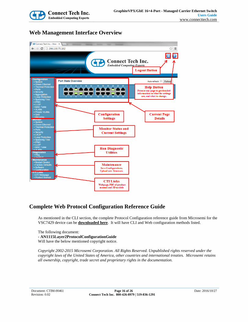
Web Management Interface Overview
Complete Web Protocol Configuration Reference Guide
As mentioned in the CLI section, the complete Protocol Configuration reference guide from Microsemi for the
VSC7429 device can be downloaded here. It will have CLI and Web configuration methods listed.
The following document:
- AN1115Layer2ProtocolConfigurationGuide
Will have the below mentioned copyright notice.
Copyright 2002-2015 Microsemi Corporation. All Rights Reserved. Unpublished rights reserved under the
copyright laws of the United States of America, other countries and international treaties. Microsemi retains
all ownership, copyright, trade secret and proprietary rights in the documentation.

GraphiteVPX/GbE 16+4-Port - Managed Carrier Ethernet Switch
Users Guide
www.connecttech.com
Document: CTIM-00461 Revision: 0.02
Page 17 of 26
Connect Tech Inc. 800-426-8979 | 519-836-1291
Date: 2016/10/27
Port LED Details The VPG uses a serialized LED stream to output the LED status for each port. This serial signal is intended to
be run through shift registers as shown below to de-serialize the stream. To accommodate the 16 ports
(VPG202 – Backplane only) requires the use of four 8-bit shift registers (or eqivilant) setup in the
configuration shown below.
An example circuit is shown below, or an example schematic can be downloaded here.

GraphiteVPX/GbE 16+4-Port - Managed Carrier Ethernet Switch
Users Guide
www.connecttech.com
Document: CTIM-00461 Revision: 0.02
Page 18 of 26
Connect Tech Inc. 800-426-8979 | 519-836-1291
Date: 2016/10/27
System Management Interface
The GraphiteVPX/GbE supports a slave I2C slave interface on the SM0 (SCL) and SM1 (SDA) signals
connected to the VPX backplane. The I2C address of this interface is determined by the Geographic Address
lines GA0#, GA1#, and GA2#. This interface operates at 100 KHz.
There are 10K OHM pull-ups to the +3.3V_AUX supply on the I2C slave interface on SM0 and SM1.
The I2C interface contains an I2C mux device (PCA9544) to allow the user access 5 temperature sensors that
monitor board edges and internal temperatures of the Ethernet Switch and Ethernet PHY.
Addressing the I2C Slave Interface (I2C Mux)
As stated above, the I2C slave interface uses GA0#, GA1#, and GA2# to determine its final I2C address. See
more details below. Refer to your backplane GA (Geographical Address) lines for the complete configuration
address.
The I2C address will be as such:
Bit7 BIT6 BIT5 BIT4 BIT3 BIT2 BIT1 BIT0
1 1 1 0 GA2# GA1# GA0# R/W

GraphiteVPX/GbE 16+4-Port - Managed Carrier Ethernet Switch
Users Guide
www.connecttech.com
Document: CTIM-00461 Revision: 0.02
Page 19 of 26
Connect Tech Inc. 800-426-8979 | 519-836-1291
Date: 2016/10/27
Writing to the I2C Slave Interface
Refer to the NXP PCA9544 datasheet for access details.
The I2C multiplexor is like a ‘gate’ to open an on board I2C bus to access one of three card side busses:
1) Bus 0 – is a link to one TMP422 (sensor #5) remote temperature sensor (local temp and remote
temperatures of VSC7429 and VSC8512).
2) Bus 1 – is a direct link with XMC sites I2C system interface
3) Bus 2 – is a link to 2 TMP101 temperature sensors on the top edge (Sensor 1 and 2)
4) Bus 3 – is a link to 2 TMP101 temperature sensors on the bottom edge (Sensor 3 and 4)
*Refer to the TI TMP101 datasheet for access and setup of ALERT pin interrupt to the PCA9544. A Thermal
Alert LED is accessible on the solder side of the card if a visual indicator is required.
Reading from the I2C devices
When reading from the I2C slave interface, the last value stored in the command register by a write operation
is used to determine which command to respond to. To change the command for a read operation, a new
command must be written to the command register. This is accomplished by issuing an I2C slave address byte
with the R/W# bit LOW, followed by the command byte. The master can then generate a START condition
and send the I2C slave address byte with the R/W# bit HIGH to initiate a read command. If repeated reads
from the same register are required it is not necessary to continually send the command byte. The slave I2C
interface will remember the original command value until it is changed by the next write operation.
Example XML code to open the I2C mux and access the temperature sensors using the Totalphase Aardvark™
USB to I2C controller can be provided by request.

GraphiteVPX/GbE 16+4-Port - Managed Carrier Ethernet Switch
Users Guide
www.connecttech.com
Document: CTIM-00461 Revision: 0.02
Page 20 of 26
Connect Tech Inc. 800-426-8979 | 519-836-1291
Date: 2016/10/27
Thermal Details
Thermal Parameters
Thermal Parameter Value
Minimum Ambient Operating Temperature -40 °C
Maximum Operating Junction Temperature 125 °C
Recommended VPG TDP 15W
SoC TDP (VSC7429) 8W
PHY TDP (VSC8512) 7W
Die junction to package case top (SoC/PHY) 3.27 °C/W
Die junction to PCB (SoC/PHY) 6.03 °C/W
Die junction to Ambient (SoC/PHY) 12.14 °C/W
Die junction to moving air @ 1 m/s (SoC/PHY) 9.42 °C/W

GraphiteVPX/GbE 16+4-Port - Managed Carrier Ethernet Switch
Users Guide
www.connecttech.com
Document: CTIM-00461 Revision: 0.02
Page 21 of 26
Connect Tech Inc. 800-426-8979 | 519-836-1291
Date: 2016/10/27
Mechanical Details
3D STEP Models A complete 3D STEP Model file of the VPX GbE Switch can be made available upon request. The VPG20x
is a Standard 3U VITA 65 unit, compliant with a 1” pitch VPX backplane layout.

GraphiteVPX/GbE 16+4-Port - Managed Carrier Ethernet Switch
Users Guide
www.connecttech.com
Document: CTIM-00461 Revision: 0.02
Page 22 of 26
Connect Tech Inc. 800-426-8979 | 519-836-1291
Date: 2016/10/27
VPG202 Top Side View

GraphiteVPX/GbE 16+4-Port - Managed Carrier Ethernet Switch
Users Guide
www.connecttech.com
Document: CTIM-00461 Revision: 0.02
Page 23 of 26
Connect Tech Inc. 800-426-8979 | 519-836-1291
Date: 2016/10/27
VPG202 – Bottom Side View

GraphiteVPX/GbE 16+4-Port - Managed Carrier Ethernet Switch
Users Guide
www.connecttech.com
Document: CTIM-00461 Revision: 0.02
Page 24 of 26
Connect Tech Inc. 800-426-8979 | 519-836-1291
Date: 2016/10/27
RTM Details The main purpose of the RTG002 is to allow the ability for development in a lab environment to access all
features and GbE channels that are available on the VPG201/VPG202. The RTM is a backplane connectable
breakout board.

GraphiteVPX/GbE 16+4-Port - Managed Carrier Ethernet Switch
Users Guide
www.connecttech.com
Document: CTIM-00461 Revision: 0.02
Page 25 of 26
Connect Tech Inc. 800-426-8979 | 519-836-1291
Date: 2016/10/27
RTG002 – Pinout Information
Photo Description
P3, J3-J10
Standard GbE RJ45 Pinouts (x16)
P1
I2C (VPX SM Bus) Header – a standard
Totalphase Aardvark™ I2C analyzer will
install without need of an adapter
Pinout
Pin 1 I2C_SCL (CLK)
Pin 2 GND
Pin 3 I2C_SDA (DATA)
P2
RJ11 Serial Interface Cable
Pinout
Pin 1 N/C
Pin 2 RX – Module Receive
Pin 3 GND
Pin 4 TX – Module Transmit
Pin 5 N/C
Pin 6 N/C

GraphiteVPX/GbE 16+4-Port - Managed Carrier Ethernet Switch
Users Guide
www.connecttech.com
Document: CTIM-00461 Revision: 0.02
Page 26 of 26
Connect Tech Inc. 800-426-8979 | 519-836-1291
Date: 2016/10/27
RTG002 – Top Side View
RTG002 – Bottom Side View


