Download - Group 2 Gear Pumps Technical Information

SAE A Pad
M10-6H thru
Group 2Gear Pumps
Technical Information
2 DKMH.PN.620.B1.02 • 520L0560 • Rev. A • 04/2003 3DKMH.PN.620.B1.02 • 520L0560 • Rev. A • 04/2003
Group 2 – Gear PumpsTechnical Information
© 2003 Sauer-Danfoss. All rights reserved.
Sauer-Danfoss accepts no responsibility for possible errors in catalogs, brochures and other printed material. Sauer-Danfoss reserves the right to alter its products without prior notice. This also applies to products already ordered provided that such alterations aren’t in conflict with agreed specifications. All trademarks in this material are properties of their respective owners. Sauer-Danfoss and the Sauer-Danfoss logotype are trademarks of the Sauer-Danfoss Group.
Front cover illustrations: F000 792, F000 793, F000 794, F005 105
Group 2 – Gear PumpsTechnical Information
2 DKMH.PN.620.B1.02 • 520L0560 • Rev. A • 04/2003 3DKMH.PN.620.B1.02 • 520L0560 • Rev. A • 04/2003
Group 2 – Gear PumpsTechnical Information
© 2003 Sauer-Danfoss. All rights reserved.
Sauer-Danfoss accepts no responsibility for possible errors in catalogs, brochures and other printed material. Sauer-Danfoss reserves the right to alter its products without prior notice. This also applies to products already ordered provided that such alterations aren’t in conflict with agreed specifications. All trademarks in this material are properties of their respective owners. Sauer-Danfoss and the Sauer-Danfoss logotype are trademarks of the Sauer-Danfoss Group.
Front cover illustrations: F000 792, F000 793, F000 794, F005 105
Group 2 – Gear PumpsTechnical InformationIntroduction
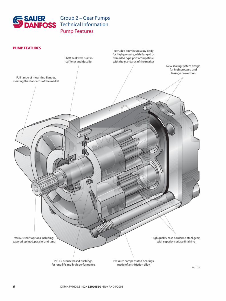
INTRODUCTION Sauer-Danfoss high performance gear pumps are fixed displacement pumps which consist of the pump housing, drive gear, driven gear, DU bushings, rear cover and front flange, shaft seal and inner / outer seals, as shown in the section drawing on page 6. The pressure balanced design of the pumps provides high efficiency for the entire series.
The standard SNP2 pumps are offered throughout the given range of displacements. There are also two special versions, the SHP 2 and the SKP 2. The SHP uses longer journal bearings to achieve a higher pressure capability in the larger displacements. The SKP is designed to accommodate an SAE 11 tooth splined shaft for higher torque applications.
• Large displacement range (from 4 to 25 cm3)• High performance at low cost• Efficient pressure balanced design• Proven reliability and performance• Optimum product configurations• Full range of auxiliary features• Compact, lightweight• Modular product design• Quiet operation• Worldwide sales and service

4 DKMH.PN.620.B1.02 • 520L0560 • Rev. A • 04/2003 5DKMH.PN.620.B1.02 • 520L0560 • Rev. A • 04/2003
Group 2 – Gear PumpsTechnical InformationContents
Group 2 – Gear PumpsTechnical InformationContents
INTRODUCTION
PUMP FEATURES
GEAR PUMP CIRCUIT
TECHNICAL DATA
MODEL CODE
TECHNICAL TERMS
SYSTEM REQUIREMENTS
PUMP LIFE
SOUND LEVELS
PUMP PERFORMANCE
PRODUCT OPTIONS
Introduction ..................................................................................................................................................... 3
Pump features ................................................................................................................................................. 6
Typical gear pump circuit............................................................................................................................ 7
Hardware specifications............................................................................................................................... 8System specifications.................................................................................................................................... 9Determination of nominal pump size..................................................................................................... 9
Model code.....................................................................................................................................................10
Definition and explanation of technical terms..................................................................................12
Hydraulic fluid ...............................................................................................................................................14Temperature and viscosity........................................................................................................................14Inlet design.....................................................................................................................................................14Fluids and filtration......................................................................................................................................15Reservoir..........................................................................................................................................................15Line sizing .......................................................................................................................................................16Pump drive .....................................................................................................................................................16
Pump drive data form ...........................................................................................................................17
Pump life..........................................................................................................................................................18
Sound levels ...................................................................................................................................................19
Pump performance .....................................................................................................................................20
Shaft options..................................................................................................................................................23Shaft availability and torque capacity.............................................................................................23
Mounting flanges.........................................................................................................................................24Nonstandard port configurations ..........................................................................................................24
Available mounting flanges ................................................................................................................24Available porting options ....................................................................................................................24
Integral priority flow divider valve.........................................................................................................25Valve operation and performance....................................................................................................26Order codes for integral priority flow divider...............................................................................31
Integral relief valve (SNE 2 / SNI 2) .........................................................................................................32Variant codes for ordering integral relief valve............................................................................32
Outrigger bearing assembly ....................................................................................................................33Available configurations.......................................................................................................................33
4 DKMH.PN.620.B1.02 • 520L0560 • Rev. A • 04/2003 5DKMH.PN.620.B1.02 • 520L0560 • Rev. A • 04/2003
Group 2 – Gear PumpsTechnical InformationContents
Group 2 – Gear PumpsTechnical InformationContents
PRODUCT OPTIONS(continued)
PRODUCT DIMENSIONAL INFORMATION
Auxiliary mounting pads ...........................................................................................................................34Auxiliary mounting pad specifications ...........................................................................................34
SC01 / CI01 / CO01 .......................................................................................................................................35SC02 / CO02....................................................................................................................................................36FR03...................................................................................................................................................................37SC04 / SC05 / CO04 / CO05 .......................................................................................................................38SC06 / CI06......................................................................................................................................................39CO09..................................................................................................................................................................40CO09 (variant BBM)......................................................................................................................................41CO0B .................................................................................................................................................................42Nonstandard port configurations ..........................................................................................................43Integral priority flow divider cover and integral relief valve cover.............................................44Outrigger bearings ......................................................................................................................................45Auxiliary mounting pad .............................................................................................................................47
6 DKMH.PN.620.B1.02 • 520L0560 • Rev. A • 04/2003 7DKMH.PN.620.B1.02 • 520L0560 • Rev. A • 04/2003
Group 2 – Gear PumpsTechnical Information
Group 2 – Gear PumpsTechnical Information
P101 000
High quality case hardened steel gearswith superior surface finishing
Pressure compensated bearingsmade of anti-friction alloy
PTFE / bronze based bushingsfor long life and high performance
Various shaft options including:tapered, splined, parallel and tang
Full range of mounting flanges,meeting the standards of the market
Shaft seal with built instiffener and dust lip
Extruded aluminium alloy bodyfor high pressure, with flanged orthreaded type ports compatiblewith the standards of the market
New sealing system designfor high pressure andleakage prevention
Pump Features
PUMP FEATURES

6 DKMH.PN.620.B1.02 • 520L0560 • Rev. A • 04/2003 7DKMH.PN.620.B1.02 • 520L0560 • Rev. A • 04/2003
Group 2 – Gear PumpsTechnical Information
Group 2 – Gear PumpsTechnical Information
P101 001E
RESERVOIR
BYPASS CHECK
HEAT EXCHANGER
WAX CAPSULETHERMAL SENSOR
Gear motor
SUCTION SCREEN
FILTER
GEAR PUMP
SYSTEM PRESSURECONTROL VALVE
PUMP INLET PUMP OUTPUT CONTROLLED FLOW RETURN FLOW PILOT FLOW
Gear Pump Circuit
This circuit shows an SNP 2 gear pump driving an SNM 2 gear motor through a system pressure control valve. The system pressure control valve regulates motor speed based on input from the wax capsule thermal sensor. Discharge from the gear motor is then returned to the reservoir through a heat exchanger, which is equipped with a bypass check valve. Oil in this circuit is cleaned by a return line filter placed between the heat exchanger and the reservoir. A suction screen in the reservoir covers the inlet line.
TYPICAL GEAR PUMP CIRCUIT
8 DKMH.PN.620.B1.02 • 520L0560 • Rev. A • 04/2003 9DKMH.PN.620.B1.02 • 520L0560 • Rev. A • 04/2003
Group 2 – Gear PumpsTechnical Information
Group 2 – Gear PumpsTechnical Information
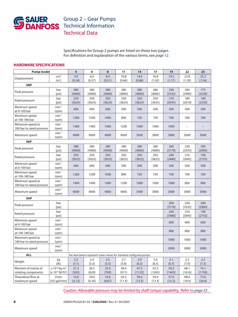
Specifications for Group 2 pumps are listed on these two pages.For definition and explanation of the various terms, see page 12.
Caution: Allowable pressure may be limited by shaft torque capability. Refer to page 23.
HARDWARE SPECIFICATIONS
Technical Data
Pump model 4 6 8 11 14 17 19 22 25
Displacementcm3
[in3]3.9
[0.24]6.0
[0.37]8.4
[0.51]10.8
[0.66]14.4
[0.88]16.8
[1.02]19.2
[1.17]22.8
[1.39]25.2
[1.54]
SNP
Peak pressurebar[psi]
280[4060]
280[4060]
280[4060]
280[4060]
280[4060]
280[4060]
230[3335]
200[2900]
175[2538]
Rated pressurebar[psi]
250[3625]
250[3625]
250[3625]
250[3625]
250[3625]
250[3625]
210[3045]
180[2610]
160[2320]
Minimum speedat 0-100 bar
min-1
(rpm)600 600 600 500 500 500 500 500 500
Minimum speedat 100-180 bar
min-1
(rpm)1200 1200 1000 800 750 750 700 700 700
Minimum speed at180 bar to rated pressure
min-1
(rpm)1400 1400 1400 1200 1000 1000 1000 – –
Maximum speedmin-1
(rpm)4000 4000 4000 4000 3500 3000 3000 3000 3000
SKP
Peak pressurebar[psi]
280[4060]
280[4060]
280[4060]
280[4060]
280[4060]
280[4060]
260[3770]
230[3335]
200[2900]
Rated pressurebar[psi]
250[3625]
250[3625]
250[3625]
250[3625]
250[3625]
250[3625]
240[3480]
210[3045]
190[2755]
Minimum speedat 0-100 bar
min-1
(rpm)600 600 600 500 500 500 500 500 500
Minimum speedat 100-180 bar
min-1
(rpm)1200 1200 1000 800 750 750 700 700 700
Minimum speed at180 bar to rated pressure
min-1
(rpm)1400 1400 1400 1200 1000 1000 1000 800 800
Maximum speedmin-1
(rpm)4000 4000 4000 4000 3500 3000 3000 3000 3000
SHP
Peak pressurebar[psi]
260[3770]
230[3335]
200[2900]
Rated pressurebar[psi]
240[3480]
210[3045]
190[2755]
Minimum speedat 0-100 bar
min-1
(rpm)600 600 600
Minimum speedat 100-180 bar
min-1
(rpm)800 800 800
Minimum speed at180 bar to rated pressure
min-1
(rpm)1000 1000 1000
Maximum speedmin-1
(rpm)3000 3000 3000
ALL The data below represent mean values for standard configured pumps
Weightkg[lb]
2.3[5.1]
2.4[5.3]
2.5[5.5]
2.7[5.8]
2.9[6.3]
3.0[6.5]
3.1[6.7]
3.2[7.0]
3.3[7.3]
Moment of inertia ofrotating components
x 10-6 kg m2
[x 10-6 lbf ft2]21.3[505]
26.5[629]
32.4[769]
38.4[911]
47.3[1122]
53.3[1265]
59.2[1405]
68.1[1616]
74.1[1758]
Theoretical flow atmaximum speed
l/min[US gal/min]
15.6[4.12]
24.0[6.34]
33.6[8.87]
43.2[11.4]
50.4[13.3]
50.4[13.3]
57.6[15.2]
68.4[18.0]
75.6[20.0]

8 DKMH.PN.620.B1.02 • 520L0560 • Rev. A • 04/2003 9DKMH.PN.620.B1.02 • 520L0560 • Rev. A • 04/2003
Group 2 – Gear PumpsTechnical Information
Group 2 – Gear PumpsTechnical InformationTechnical Data
Inlet pressure - bar absoluteRecommended range: 0.8 to 3.0Minimum (cold start): 0.6
Fluid viscosity - mm2/s [SUS]Minimum: 10 [60]Recommended range: 12 to 60 [66 to 280]Maximum (cold start): 1600 [7500]
Temperature - °C [°F]Minimum (cold start): -20 [-4]Maximum continuous: 80 [176]Peak (intermittent): 90 [194]
Fluid cleanliness level and βx ratioFluid cleanliness level (per ISO 4406): Class 18/13 or betterβx ratio (suction filtration): β35-45 = 75 and β10 = 2βx ratio (pressure or return filtration): β10 = 75Recommended inlet screen size: 100-125 µm
Unit: Metric system: Inch system
Vg • n • ηv Vg • n • ηvOutput flow Q = l/min Q = [US gal/min] 1000 231
Vg • ∆p Vg • ∆pInput torque M = Nm M = [lbf•in] 20 • π • ηm 2 • π • ηm
Vg • n • ∆p Vg • n • ∆p Input power P = kW P = [hp] 600 000 • ηm 396 000 • ηm
Vg = Pump displacement per revolution cm3 [in3]n = Pump speed min-1 (rpm)∆p = System pressure bar [psi] ∆p = po - pi
ηv = Pump volumetric efficiencyηm = Pump mechanical efficiencyηt = Pump overall efficiency ηt = ηv • ηm
po = Outlet pressure bar [psi]pi = Inlet pressure bar [psi]
SYSTEM SPECIFICATIONS
DETERMINATION OF NOMINAL PUMP SIZE

10 DKMH.PN.620.B1.02 • 520L0560 • Rev. A • 04/2003 11DKMH.PN.620.B1.02 • 520L0560 • Rev. A • 04/2003
Group 2 – Gear PumpsTechnical Information
Group 2 – Gear PumpsTechnical Information
Model Code
Type SNP 2 = Standard Gear Pump SKP 2 = High Torque Gear Pump SHP 2 = High Pressure Gear Pump SNI 2 = Gear Pump with Internal Drain Relief Valve SNE 2 = Gear Pump with External Drain Relief ValveValve (omit when not used) U = Priority Flow Divider with Pilot Relief Valve L = Priority Flow Divider with Pilot Relief Valve and Static Load Sensing N = Priority Flow Divider with Pilot Relief Valve and Dynamic Load Sensing P = Priority Flow Divider with Full Flow Relief Valve R = Priority Flow Divider with Full Flow Relief Valve and Static Load Sensing V = Priority Flow Divider with Full Flow Relief Valve and Dynamic Load SensingValve Port Position (omit when not used) S = Side Ports F = Rear PortsDisplacement – cm3/rev [in3/rev] 4 = 3.9 [0.24] 6 = 6.0 [0.37] 8 = 8.4 [0.51] 11 = 10.8 [0.66] 14 = 14.4 [0.88] 17 = 16.8 [1.03] 19 = 19.2 [1.17] 22 = 22.8 [1.39] 25 = 25.2 [1.54]Direction of Rotation D = Right (Clockwise) S = Left (Anti-clockwise)Input Shaft / Mounting Flange / Port ConfigurationCO Tapered shafts, 1:5 or 1:8 CO01 = 1:8 tapered shaft / European four bolt flange / European flanged ports CO02 = 1:5 tapered shaft / German four bolt PTO flange / German standard ports CO04 = 1:5 tapered shaft / German two bolt PTO flange (Deutz) / German standard ports CO05 = 1:5 tapered shaft / German two bolt PTO flange (Deutz) / German standard ports CO09 = 1:8 tapered shaft / Perkins 4.236 timing case flange / European flanged ports CO09 = (variant BBM) 1:8 tapered shaft / Perkins 900 series flange / German standard ports CO0B = 1:8 tapered shaft / Perkins 1000 series left side PTO flange / European flanged ports CO91 = (variant LBD) 1:8 tapered shaft / European four bolt flange / European flanged ports / equipped with outrigger bearing CO94 = 1:5 tapered shaft / German two bolt PTO flange (Deutz) / German standard ports / equipped with outrigger bearingCI Parallel shafts, 15mm or 15.875mm CI01 = 15mm [0.591 in] parallel shaft / European four bolt flange / European flanged ports CI06 = 15.875mm [0.625 in] parallel shaft / SAE "A" flange / SAE O-ring boss ports CI96 = (variant LEP) 19.05mm [0.750 in] parallel shaft / SAE "A" flange / SAE O-ring boss ports / equipped with outrigger bearingSC Splined shafts, DIN B17x14, SAE 9T 16/32p, or SAE 11T 16/32p (SKP 2 only) SC01 = DIN splined shaft / European four bolt flange / European flanged ports SC02 = DIN splined shaft / German four bolt PTO flange / German standard ports SC04 = DIN splined shaft / German two bolt PTO flange (Deutz) / German standard ports SC05 = DIN splined shaft / German two bolt PTO flange (Deutz) / German standard ports SC06 = SAE splined shaft / SAE A flange / SAE O-ring boss ports SC36 = SAE splined shaft / SAE A flange plus SAE A auxiliary mounting pad / SAE O-ring boss portsFR Sauer-Danfoss tang shaft FR03 = Sauer-Danfoss tang shaft / flanged for multiple configuration / German standard ports
/
A B C D E F H L M N P R SMODEL CODE
10 DKMH.PN.620.B1.02 • 520L0560 • Rev. A • 04/2003 11DKMH.PN.620.B1.02 • 520L0560 • Rev. A • 04/2003
Group 2 – Gear PumpsTechnical Information
Group 2 – Gear PumpsTechnical InformationModel Code
/
A B C D E F H L M N P R S
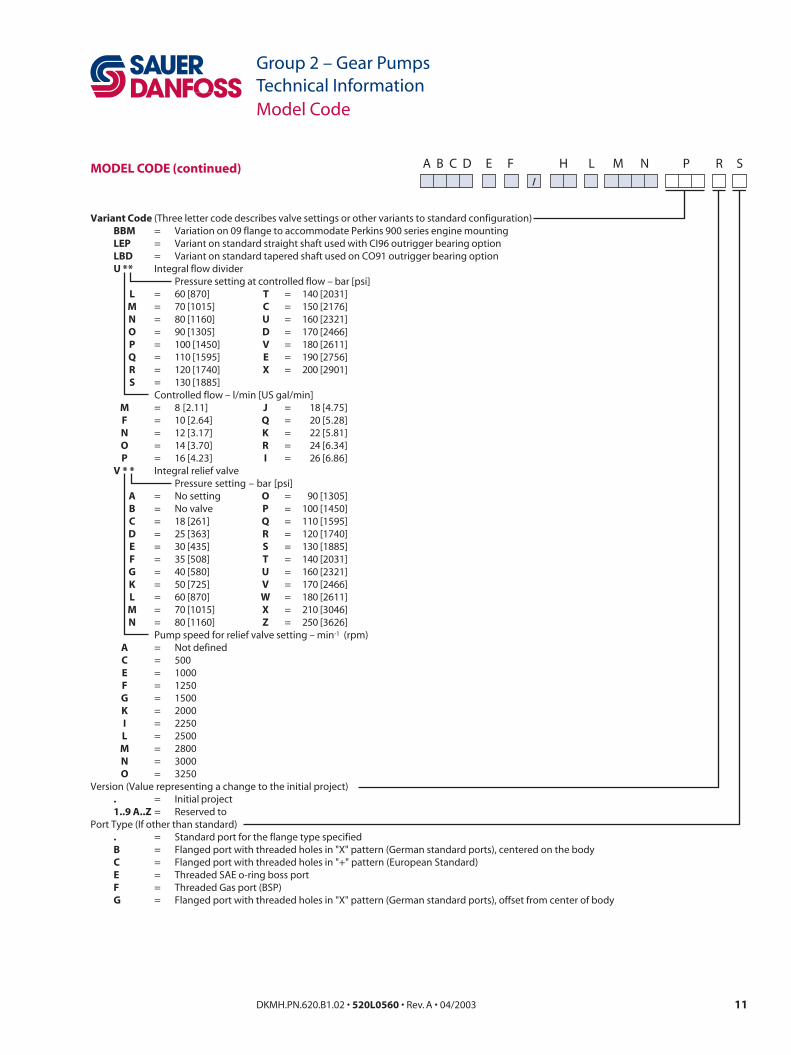
Variant Code (Three letter code describes valve settings or other variants to standard configuration) BBM = Variation on 09 flange to accommodate Perkins 900 series engine mounting LEP = Variant on standard straight shaft used with CI96 outrigger bearing option LBD = Variant on standard tapered shaft used on CO91 outrigger bearing option U * * Integral flow divider Pressure setting at controlled flow – bar [psi] L = 60 [870] T = 140 [2031] M = 70 [1015] C = 150 [2176] N = 80 [1160] U = 160 [2321] O = 90 [1305] D = 170 [2466] P = 100 [1450] V = 180 [2611] Q = 110 [1595] E = 190 [2756] R = 120 [1740] X = 200 [2901] S = 130 [1885] Controlled flow – l/min [US gal/min] M = 8 [2.11] J = 18 [4.75] F = 10 [2.64] Q = 20 [5.28] N = 12 [3.17] K = 22 [5.81] O = 14 [3.70] R = 24 [6.34] P = 16 [4.23] I = 26 [6.86] V * * Integral relief valve Pressure setting – bar [psi] A = No setting O = 90 [1305] B = No valve P = 100 [1450] C = 18 [261] Q = 110 [1595] D = 25 [363] R = 120 [1740] E = 30 [435] S = 130 [1885] F = 35 [508] T = 140 [2031] G = 40 [580] U = 160 [2321] K = 50 [725] V = 170 [2466] L = 60 [870] W = 180 [2611] M = 70 [1015] X = 210 [3046] N = 80 [1160] Z = 250 [3626] Pump speed for relief valve setting – min-1 (rpm) A = Not defined C = 500 E = 1000 F = 1250 G = 1500 K = 2000 I = 2250 L = 2500 M = 2800 N = 3000 O = 3250Version (Value representing a change to the initial project) . = Initial project 1..9 A..Z = Reserved toPort Type (If other than standard) . = Standard port for the flange type specified B = Flanged port with threaded holes in "X" pattern (German standard ports), centered on the body C = Flanged port with threaded holes in "+" pattern (European Standard) E = Threaded SAE o-ring boss port F = Threaded Gas port (BSP) G = Flanged port with threaded holes in "X" pattern (German standard ports), offset from center of body
MODEL CODE (continued)

12 DKMH.PN.620.B1.02 • 520L0560 • Rev. A • 04/2003 13DKMH.PN.620.B1.02 • 520L0560 • Rev. A • 04/2003
Group 2 – Gear PumpsTechnical Information
Group 2 – Gear PumpsTechnical Information
Maximum speed is the speed limit recommended when operating at rated pressure. It is the highest speed at which normal life can be expected.
Minimum speed is the lower limit of operating speed. It is the lowest speed at which normal bearing life can be expected. It is important to note that the minimum speed increases as operating pressure increases. When operating under higher pressures, a higher minimum speed must be maintained (see graph below).
System pressure is the differential of pressure between the outlet and inlet ports. It is a dominant operating variable affecting hydraulic unit life. High system pressure, which results from high load, reduces expected life. System pressure must remain at or below rated pressure during normal operation to achieve expected life.
Rated pressure is the average, regularly occurring operating pressure that should yield satisfactory product life. It can be determined by the maximum machine load demand. For all systems the load should move below this pressure.
Peak pressure is the highest intermittent pressure allowed, and is determined by the relief valve over shoot (reaction time). Peak pressure is assumed to occur for less than 100 ms in duration.
Inlet pressure must be controlled in order to achieve expected life and performance. A continuous inlet pressure less than those shown in the table above would indicate inadequate inlet design or a restricted inlet screen. Lower inlet pressures during cold start should be expected, but should improve quickly as the fluid warms.
Technical Terms
DEFINITION AND EXPLANATION OF TECHNICAL TERMS
Rated
Pres
sure
0
SpeedMAX
T101 005E
OperatingEnvelope
N10 N2 N3
P1
P2
Peak Pressure
Rated Pressure
Pres
sure
Time
Reaction time (100ms max)
T101 006E
Where: N1 = Minimum speed at 100 bar N2 = Minimum speed at 180 bar N3 = Minimum speed at rated pressure
Inlet pressure – bar absolute
Recommended range 0.8 to 3.0
Minimum (cold start) 0.6

12 DKMH.PN.620.B1.02 • 520L0560 • Rev. A • 04/2003 13DKMH.PN.620.B1.02 • 520L0560 • Rev. A • 04/2003
Group 2 – Gear PumpsTechnical Information
Group 2 – Gear PumpsTechnical InformationNotes
14 DKMH.PN.620.B1.02 • 520L0560 • Rev. A • 04/2003 15DKMH.PN.620.B1.02 • 520L0560 • Rev. A • 04/2003
Group 2 – Gear PumpsTechnical Information
Group 2 – Gear PumpsTechnical Information
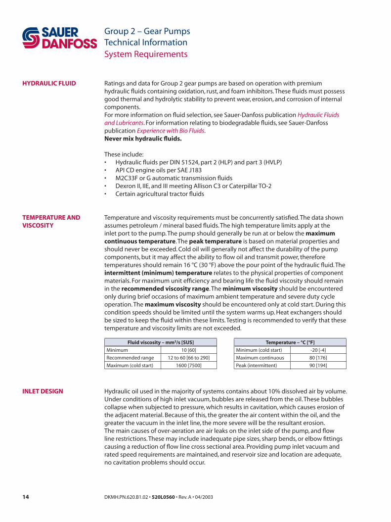
Ratings and data for Group 2 gear pumps are based on operation with premium hydraulic fluids containing oxidation, rust, and foam inhibitors. These fluids must possess good thermal and hydrolytic stability to prevent wear, erosion, and corrosion of internal components.For more information on fluid selection, see Sauer-Danfoss publication Hydraulic Fluids and Lubricants. For information relating to biodegradable fluids, see Sauer-Danfoss publication Experience with Bio Fluids.Never mix hydraulic fluids.
These include:• Hydraulic fluids per DIN 51524, part 2 (HLP) and part 3 (HVLP)• API CD engine oils per SAE J183• M2C33F or G automatic transmission fluids• Dexron II, IIE, and III meeting Allison C3 or Caterpillar TO-2• Certain agricultural tractor fluids
Temperature and viscosity requirements must be concurrently satisfied. The data shown assumes petroleum / mineral based fluids. The high temperature limits apply at the inlet port to the pump. The pump should generally be run at or below the maximum continuous temperature. The peak temperature is based on material properties and should never be exceeded. Cold oil will generally not affect the durability of the pump components, but it may affect the ability to flow oil and transmit power, therefore temperatures should remain 16 °C (30 °F) above the pour point of the hydraulic fluid. The intermittent (minimum) temperature relates to the physical properties of component materials. For maximum unit efficiency and bearing life the fluid viscosity should remain in the recommended viscosity range. The minimum viscosity should be encountered only during brief occasions of maximum ambient temperature and severe duty cycle operation. The maximum viscosity should be encountered only at cold start. During this condition speeds should be limited until the system warms up. Heat exchangers should be sized to keep the fluid within these limits. Testing is recommended to verify that these temperature and viscosity limits are not exceeded.
Hydraulic oil used in the majority of systems contains about 10% dissolved air by volume. Under conditions of high inlet vacuum, bubbles are released from the oil. These bubbles collapse when subjected to pressure, which results in cavitation, which causes erosion of the adjacent material. Because of this, the greater the air content within the oil, and the greater the vacuum in the inlet line, the more severe will be the resultant erosion.The main causes of over-aeration are air leaks on the inlet side of the pump, and flow line restrictions. These may include inadequate pipe sizes, sharp bends, or elbow fittings causing a reduction of flow line cross sectional area. Providing pump inlet vacuum and rated speed requirements are maintained, and reservoir size and location are adequate, no cavitation problems should occur.
System Requirements
HYDRAULIC FLUID
TEMPERATURE AND VISCOSITY
INLET DESIGN
Fluid viscosity – mm2/s [SUS]
Minimum 10 [60]
Recommended range 12 to 60 [66 to 290]
Maximum (cold start) 1600 [7500]
Temperature – °C [°F]
Minimum (cold start) -20 [-4]
Maximum continuous 80 [176]
Peak (intermittent) 90 [194]

14 DKMH.PN.620.B1.02 • 520L0560 • Rev. A • 04/2003 15DKMH.PN.620.B1.02 • 520L0560 • Rev. A • 04/2003
Group 2 – Gear PumpsTechnical Information
Group 2 – Gear PumpsTechnical Information
To prevent premature wear, it is imperative that only clean fluid enter the pump and hydraulic circuit. A filter capable of controlling the fluid cleanliness to Class 18/13 per ISO 4406 or better under normal operating conditions is recommended.The filter may be located on the pump outlet (pressure filtration), inlet (suction filtration), or the reservoir return (return line filtration).The selection of a filter depends on a number of factors including the contaminant ingression rate, the generation of contaminants in the system, the required fluid cleanliness, and the desired maintenance interval. Contaminant ingression rate is determined (among other things) by the type of actuators used in the system. Hydraulic cylinders normally cause higher levels of contamination to enter the system.Filters are selected to meet these requirements using rating parameters of efficiency and capacity. Filter efficiency may be measured with a Beta ratio1 (βX). For suction filtration, with controlled reservoir ingression, a filter with β35-45 = 75 (and β10 = 2) or better has been found to be satisfactory. For return or pressure filtration, filters with an efficiency of β10 = 75 are typically required.Since each system is unique, the filtration requirements for that system will be unique and must be determined by test in each case. Filtration system acceptability should be judged by monitoring of prototypes, evaluation of components, and performance throughout the test program.See Sauer-Danfoss publications Hydraulic Fluids and Lubricants and Experience with Bio Fluids for more information.
(1) Filter βx ratio is a measure of filter efficiency defined by ISO 4572. It is defined as the ratio of the number of particles greater than a given diameter (“x” in microns) upstream of the filter to the number of these particles downstream of the filter.
Fluid cleanliness level and βx ratio
Fluid cleanliness level (per ISO 4406) Class 18/13 or better
βx ratio (suction filtration) β35-45 = 75 and β10 = 2
βx ratio (pressure or return filtration) β10 = 75
Recommended inlet screen size 100-125 µm [0.004-0.005 in]
The function of the reservoir is to provide clean fluid, dissipate heat, remove entrained air, and allow for fluid volume changes associated with fluid expansion and cylinder differential volumes.The reservoir should be designed to accommodate maximum volume changes during all system operating modes and to promote deaeration of the fluid as it passes through the tank. The design should accommodate a fluid dwell time between 60 and 180 seconds to allow entrained air to escape.Minimum reservoir capacity depends on the volume needed to cool the oil, hold the oil from all retracted cylinders, and allow expansion due to temperature changes. Normally, a fluid volume of 1 to 3 times the pump output flow (per minute) is satisfactory. The minimum reservoir capacity is recommended to be 125% of the fluid volume.The suction line should be located above the bottom of the reservoir to take advantage of gravity separation and prevent large foreign particles from entering the line. A 100 -125 µm [0.004-0.005 in] screen covering the suction line is recommended. To minimize vacuum at the pump inlet, it is recommended that the pump be located below the lowest expected fluid level.The return line should be positioned to allow discharge below the lowest fluid level, and directed into the interior of the reservoir for maximum dwell and efficient deaeration.A baffle (or baffles) between the return line and suction line will promote deaeration and reduce surging of the fluid.
System Requirements
FLUIDS AND FILTRATION
RESERVOIR

16 DKMH.PN.620.B1.02 • 520L0560 • Rev. A • 04/2003 17DKMH.PN.620.B1.02 • 520L0560 • Rev. A • 04/2003
Group 2 – Gear PumpsTechnical Information
Group 2 – Gear PumpsTechnical Information
The choice of piping size and installation should always be consistent with maintaining minimum fluid velocity. This will reduce system noise, pressure drops and overheating, thereby maximizing system life and performance. Inlet piping should be designed to maintain continuous pump inlet pressures above 0.8 bar absolute during normal operation. The inlet line velocity should not exceed 2.5 m/s. Pump outlet line velocity should not exceed 5 m/s. System return lines should be limited to 3 m/s.
With a choice between tapered, splined, or parallel shafts, Sauer-Danfoss gear pumps are suitable for a wide range of direct and indirect drive applications. Typically these applications use a plug-in, belt, or gear to drive the pump input shaft. Group 2 pumps are designed with bearings that can accept some incidental external radial and thrust loads. However, any amount of external load may reduce the expected bearing life. An outrigger bearing is available to accommodate these loads and is shown on page 33.For in-line drive applications, it is recommended that a three piece coupling be used to minimize radial or thrust shaft loads. Plug-in drives, acceptable only with spline shaft configurations, can impose severe radial loads on the pump shaft when the mating spline is rigidly supported. Increased spline clearance does not alleviate this condition. The use of plug in drives is permissible providing that the concentricity between the mating spline and pilot diameter is within 0.1 mm [0.004 in]. The drive should be lubricated by flooding with oil.The allowable radial shaft loads are a function of the load position, the load orientation, and the operating pressure of the hydraulic pump. All external shaft loads will have an effect on bearing life and may affect pump performance. In applications where external shaft loads cannot be avoided, the impact on the pump can be minimized by optimizing the orientation and magnitude of the load. A tapered input shaft is recommended for applications where radial shaft loads are present. Spline shafts are not recommended for belt or gear drive applications. For belt drive applications, a spring loaded belt tension device is recommended to avoid excessive belt tension.Thrust (axial) loads in either direction should be avoided. If continuously applied external radial or thrust loads are known to occur, contact Sauer- Danfoss for evaluation.
Contact your Sauer-Danfoss representative for assistance when applying pumps with radial or thrust loads.
System Requirements
LINE SIZING
PUMP DRIVE
Pilot Cavity
Mating Spline
Ø 0.1 [0.004]
P101 002E
Mating spline

16 DKMH.PN.620.B1.02 • 520L0560 • Rev. A • 04/2003 17DKMH.PN.620.B1.02 • 520L0560 • Rev. A • 04/2003
Group 2 – Gear PumpsTechnical Information
Group 2 – Gear PumpsTechnical Information
Pump drive data formPhoto copy this page and fax the completed form to your Sauer-Danfoss representative for assistance in applying pumps with belt or gear drive.
System Requirements
PUMP DRIVE (continued)
90˚
180˚ 0˚
270˚
α
90˚
180˚ 0˚
270˚
α
P
dw
a
a
P101 003E
Inletport
Inletport
dw
Application data
Pump displacement cc/rev
Rated system pressure bar
psi
Relief valve setting bar
psi
Pump shaft rotation left
right
Pump minimum speedmin-1
(rpm)
Pump maximum speedmin-1
(rpm)
Drive gear helix angle
(gear drive only)deg.
Belt type
(belt drive only)
V
Notch
Belt tension
(belt drive only)P
N
lbf
Angular orientation of
gear or belt to inlet portα deg.
Pitch diameter of gear dw
mm
in
Distance from flange to
center of gear or pulleya
mm
in
18 DKMH.PN.620.B1.02 • 520L0560 • Rev. A • 04/2003 19DKMH.PN.620.B1.02 • 520L0560 • Rev. A • 04/2003
Group 2 – Gear PumpsTechnical Information
Group 2 – Gear PumpsTechnical Information
All Sauer-Danfoss gear pumps utilize hydrodynamic journal bearings, which have an oil film maintained between the gear / shaft and bearing surfaces at all times. If this oil film is sufficiently sustained through proper system maintenance and operating within recommended limits, long life can be expected.
A B10 type life expectancy number is generally associated with rolling element bearings and does not exist for hydrodynamic bearings.
Pump life is defined as the life expectancy of the hydraulic components and is a function of speed, system pressure, and other system parameters such as oil cleanliness. High pressure, which results from high load, reduces expected life in a manner similar to many mechanical assemblies such as engines and gearboxes. When reviewing an application, it is desirable to have projected machine duty cycle data, which includes percentages of time at various loads and speeds.Prototype testing programs to verify operating parameters and their impact on life expectancy are strongly recommended prior to finalizing any system design.
Pump Life
PUMP LIFE
18 DKMH.PN.620.B1.02 • 520L0560 • Rev. A • 04/2003 19DKMH.PN.620.B1.02 • 520L0560 • Rev. A • 04/2003
Group 2 – Gear PumpsTechnical Information
Group 2 – Gear PumpsTechnical Information
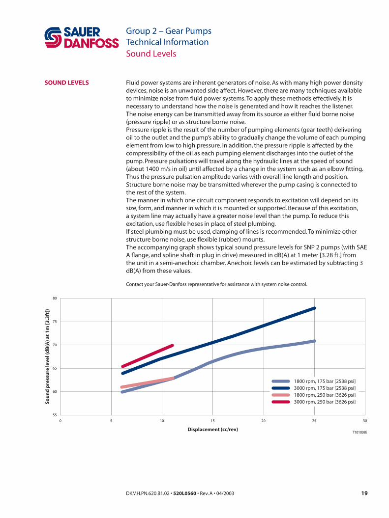
Fluid power systems are inherent generators of noise. As with many high power density devices, noise is an unwanted side affect. However, there are many techniques available to minimize noise from fluid power systems. To apply these methods effectively, it is necessary to understand how the noise is generated and how it reaches the listener.The noise energy can be transmitted away from its source as either fluid borne noise (pressure ripple) or as structure borne noise.Pressure ripple is the result of the number of pumping elements (gear teeth) delivering oil to the outlet and the pump’s ability to gradually change the volume of each pumping element from low to high pressure. In addition, the pressure ripple is affected by the compressibility of the oil as each pumping element discharges into the outlet of the pump. Pressure pulsations will travel along the hydraulic lines at the speed of sound (about 1400 m/s in oil) until affected by a change in the system such as an elbow fitting. Thus the pressure pulsation amplitude varies with overall line length and position.Structure borne noise may be transmitted wherever the pump casing is connected to the rest of the system.The manner in which one circuit component responds to excitation will depend on its size, form, and manner in which it is mounted or supported. Because of this excitation, a system line may actually have a greater noise level than the pump. To reduce this excitation, use flexible hoses in place of steel plumbing.If steel plumbing must be used, clamping of lines is recommended. To minimize other structure borne noise, use flexible (rubber) mounts.The accompanying graph shows typical sound pressure levels for SNP 2 pumps (with SAE A flange, and spline shaft in plug in drive) measured in dB(A) at 1 meter [3.28 ft.] from the unit in a semi-anechoic chamber. Anechoic levels can be estimated by subtracting 3 dB(A) from these values.
Contact your Sauer-Danfoss representative for assistance with system noise control.
SOUND LEVELS
10 15 20 25 30
80
75
70
65
60
55
Displacement (cc/rev)
Sou
nd
pre
ssu
re le
vel (
dB
(A) a
t 1
m [3
.3ft
])
1800 rpm, 175 bar [2538 psi]3000 rpm, 175 bar [2538 psi]1800 rpm, 250 bar [3626 psi]3000 rpm, 250 bar [3626 psi]
T101 008E
0 5
Sound Levels

20 DKMH.PN.620.B1.02 • 520L0560 • Rev. A • 04/2003 21DKMH.PN.620.B1.02 • 520L0560 • Rev. A • 04/2003
Group 2 – Gear PumpsTechnical Information
Group 2 – Gear PumpsTechnical Information
The following performance graphs pro-vide typical output flow and input power for Group 2 pumps at various working pressures. Data was taken using ISO VG46 petroleum / mineral based fluid at 50 °C [122 °F] (viscosity = 28 mm2/s [132 SUS]).
Pump Performance
35
5
10
15
20
25
30
5
10
15
0 40001000 2000 3000
Flo
w (l
/min
)
9.0
1.0
2.0
3.0
4.0
5.0
6.0
7.0
8.0Fl
ow
(US
gal
/min
)
0
5
10
15
20
250
bar250 bar
150 bar
100 bar
7 bar
T101 011EPo
wer
(HP)
Pow
er (k
W)
Speed min-1 (rpm)
0
SNP2/SKP2 8cc
2
4
6
8
10
12
0
2
4
6
8
10
12
14
16
0 40001000 2000 3000
250 bar
150 bar
100 bar
T101 010E
Pow
er (H
P)
Pow
er (k
W)
Speed min-1 (rpm)
26
6
8
10
12
14
18
20
22
246.5
1.5
1.0
2.0
2.5
3.0
3.5
4.0
4.5
5.0
5.5
6.0
250
bar7 bar
4
2
Flo
w (U
S g
al/m
in)
Flo
w (l
/min
)
0.5
0
SNP2/SKP2 6cc
0 40001000 2000 3000
16
14
12
10
8
6
4
2
8
6
4
2
Flo
w (l
/min
)
Flo
w (U
S g
al/m
in)
Pow
er (k
W)
Pow
er (H
P)
4.0
0.5
1.0
1.5
2.0
2.5
3.0
3.5
0
2
4
6
8
10
12
250
bar
250 bar
150 bar
100 bar
7 bar
Speed min-1 (rpm)T101 009E
SNP2/SKP2 4cc
0
5
10
15
20
25
0
5
10
15
20
25
30
35
0 500 1500 2500 3500
250 bar
150 bar
100 bar
T101 013ESpeed min-1 (rpm)
Pow
er (k
W)
Pow
er (H
P)
50
5
10
15
20
25
30
35
40
45
13
2
3
4
5
6
7
8
9
10
11
12
250
bar
7 ba
r
Flo
w (U
S g
al/m
in)
Flo
w (l
/min
)
1
0
SNP2/SKP2 14cc
5
10
15
20
0
5
10
15
20
25
30
0 40001000 2000 3000
250 bar
150 bar
100 bar
T101 012ESpeed min-1 (rpm)
Pow
er (k
W)
Pow
er (H
P)
50
5
10
15
20
25
30
35
40
45
13
2
3
4
5
6
7
8
9
10
11
12
250
bar
7 bar
Flo
w (U
S g
al/m
in)
Flo
w (l
/min
)
1
0
SNP2/SKP2 11cc
PUMP PERFORMANCE

20 DKMH.PN.620.B1.02 • 520L0560 • Rev. A • 04/2003 21DKMH.PN.620.B1.02 • 520L0560 • Rev. A • 04/2003
Group 2 – Gear PumpsTechnical Information
Group 2 – Gear PumpsTechnical InformationPump Performance
5
10
15
20
25
30
0 1000 2000 30000
5
10
15
20
25
30
35
40
45
210 bar
150 bar
100 bar
T101 015E
Pow
er (k
W)
Pow
er (H
P)
Speed min-1 (rpm)
60
5
10
15
20
25
30
35
40
45
50
5515
2
3
4
5
6
7
8
9
10
11
12
13
14
210
bar7
bar
Flo
w (U
S g
al/m
in)
Flo
w (l
/min
)
1
0
SNP2/SKP2 19cc
5
10
15
20
25
0
5
10
15
20
25
30
35
0 1000 2000 3000
250 bar
150 bar
100 bar
T101 014ESpeed min-1 (rpm)
Pow
er (k
W)
Pow
er (H
P)
50
5
10
15
20
25
30
35
40
45
13
2
3
4
5
6
7
8
9
10
11
12
250
bar
7 ba
r
Flo
w (U
S g
al/m
in)
Flo
w (l
/min
)
1
0
SNP2/SKP2 17cc
80
10
20
30
40
60
70
50
10
20
30
0 1000 2000 3000
21
3
5
7
9
11
13
15
17
19
0
10
20
30
40
160
bar160 bar
100 bar
7 bar
T101 017E
Flo
w (U
S g
al/m
in)
Flo
w (l
/min
)
Pow
er (k
W)
Pow
er (H
P)
Speed min-1 (rpm)
SNP2/SKP2 25cc
70
10
15
20
25
30
35
40
45
50
55
60
65
4
8
12
16
20
24
0 1000 2000 3000
18
3
4
5
6
7
8
9
10
11
12
13
14
15
16
17
0
5
10
15
20
25
30
35180
bar
180 bar
150 bar
100 bar
7 bar
T101 016E
Flo
w (U
S g
al/m
in)
Flo
w (l
/min
)
Pow
er (k
W)
Pow
er (H
P)
Speed min-1 (rpm)
5
SNP2/SKP2 22cc
PUMP PERFORMANCE(continued)

22 DKMH.PN.620.B1.02 • 520L0560 • Rev. A • 04/2003 23DKMH.PN.620.B1.02 • 520L0560 • Rev. A • 04/2003
Group 2 – Gear PumpsTechnical Information
Group 2 – Gear PumpsTechnical Information
Pump Performance
SHP2 22cc
210
bar7
bar
210 bar
150 bar
100 bar
70
10
15
20
25
30
35
40
45
50
55
60
65
4
8
12
16
20
24
0 1000 2000 3000
18
3
4
5
6
7
8
9
10
11
12
13
14
15
16
17
0
5
10
15
20
25
30
35
T101 019E
Flo
w (U
S g
al/m
in)
Flo
w (l
/min
)
Pow
er (k
W)
Pow
er (H
P)
Speed min-1 (rpm)
5
7 bar
240
bar
240 bar
150 bar
100 bar
SHP2 19cc
5
10
15
20
25
30
0 1000 2000 30000
5
10
15
20
25
30
35
40
45
T101 018EPo
wer
(kW
)
Pow
er (H
P)
Speed min-1 (rpm)
60
5
10
15
20
25
30
35
40
45
50
5515
2
3
4
5
6
7
8
9
10
11
12
13
14
Flo
w (U
S g
al/m
in)
Flo
w (l
/min
)
1
0
SHP2 25cc
7 bar
190
bar
190 bar150 bar
100 bar
80
10
20
30
40
60
70
50
10
20
30
0 1000 2000 3000
21
3
5
7
9
11
13
15
17
19
0
10
20
30
40
T101 020E
Flo
w (U
S g
al/m
in)
Flo
w (l
/min
)
Pow
er (k
W)
Pow
er (H
P)
Speed min-1 (rpm)
PUMP PERFORMANCE(continued)
22 DKMH.PN.620.B1.02 • 520L0560 • Rev. A • 04/2003 23DKMH.PN.620.B1.02 • 520L0560 • Rev. A • 04/2003
Group 2 – Gear PumpsTechnical Information
Group 2 – Gear PumpsTechnical Information
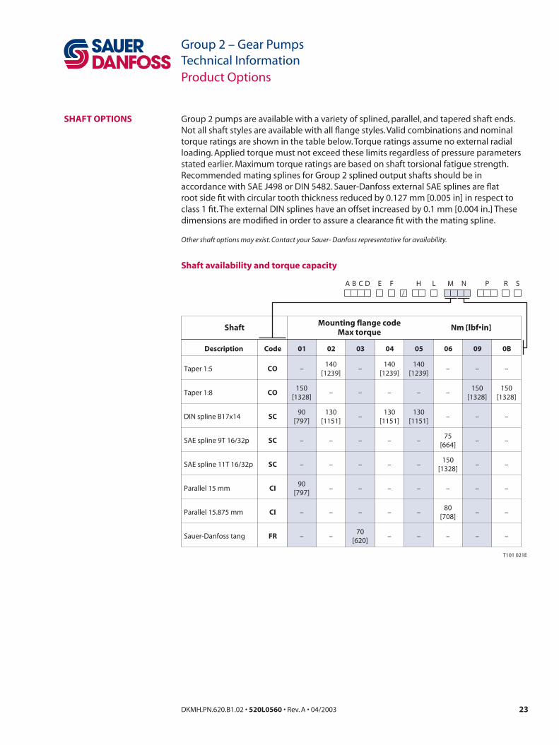
Group 2 pumps are available with a variety of splined, parallel, and tapered shaft ends. Not all shaft styles are available with all flange styles. Valid combinations and nominal torque ratings are shown in the table below. Torque ratings assume no external radial loading. Applied torque must not exceed these limits regardless of pressure parameters stated earlier. Maximum torque ratings are based on shaft torsional fatigue strength.Recommended mating splines for Group 2 splined output shafts should be in accordance with SAE J498 or DIN 5482. Sauer-Danfoss external SAE splines are flat root side fit with circular tooth thickness reduced by 0.127 mm [0.005 in] in respect to class 1 fit. The external DIN splines have an offset increased by 0.1 mm [0.004 in.] These dimensions are modified in order to assure a clearance fit with the mating spline.
Other shaft options may exist. Contact your Sauer- Danfoss representative for availability.
Shaft availability and torque capacity
Product Options
SHAFT OPTIONS
Description
Shaft Nm [lbf•in]Mounting flange code
Max torque
Taper 1:5
Taper 1:8
DIN spline B17x14
SAE spline 9T 16/32p
SAE spline 11T 16/32p
Parallel 15 mm
Parallel 15.875 mm
Sauer-Danfoss tang
Code
CO
CO
SC
SC
SC
CI
CI
FR
01
–
150[1328]
90[797]
–
–
90[797]
–
–
02
140[1239]
–
130[1151]
–
–
–
–
–
03
–
–
–
–
–
–
–
70[620]
04
140[1239]
–
130[1151]
–
–
–
–
–
05
140[1239]
–
130[1151]
–
–
–
–
–
06
–
–
–
75[664]
150[1328]
–
80[708]
–
09
–
150[1328]
–
–
–
–
–
–
0B
–
150[1328]
–
–
–
–
–
–
T101 021E
E F/
SA B C D H L M N P R
24 DKMH.PN.620.B1.02 • 520L0560 • Rev. A • 04/2003 25DKMH.PN.620.B1.02 • 520L0560 • Rev. A • 04/2003
Group 2 – Gear PumpsTechnical Information
Group 2 – Gear PumpsTechnical Information
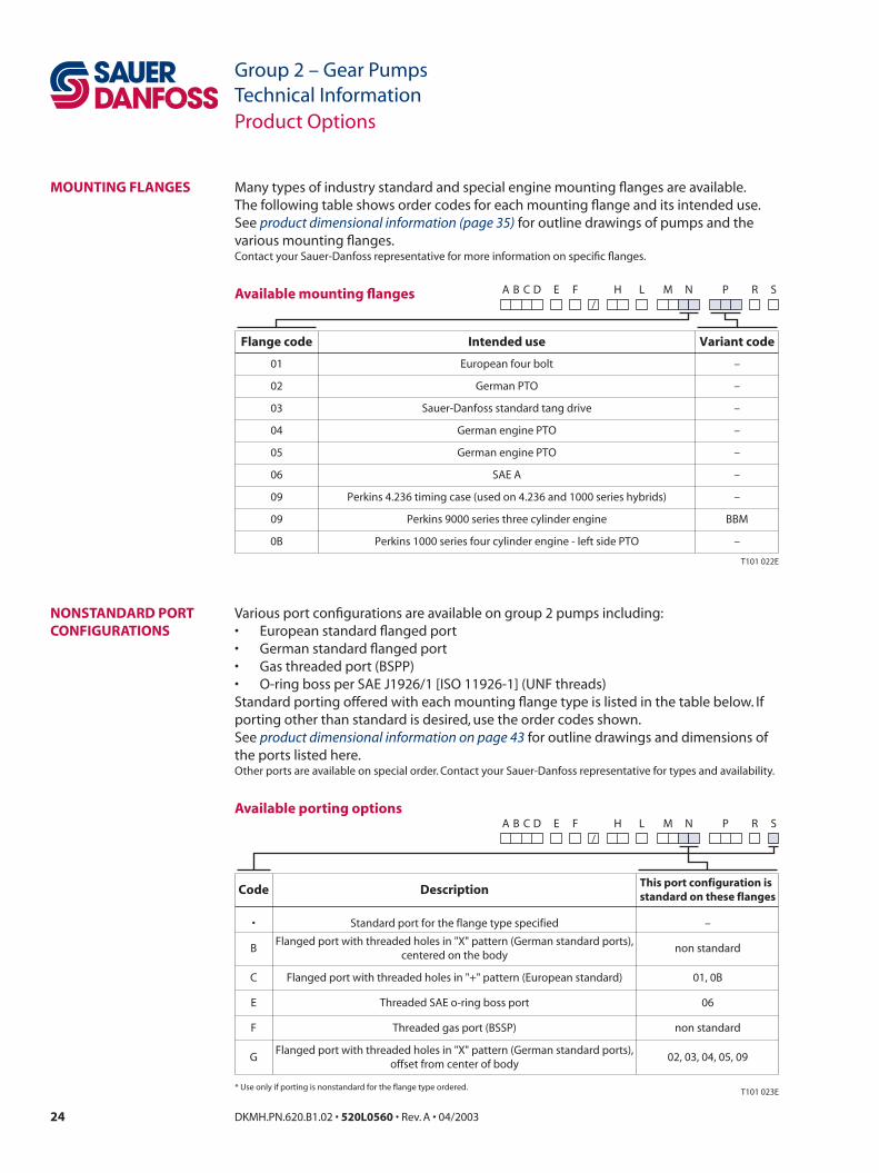
Many types of industry standard and special engine mounting flanges are available.The following table shows order codes for each mounting flange and its intended use.See product dimensional information (page 35) for outline drawings of pumps and the various mounting flanges.Contact your Sauer-Danfoss representative for more information on specific flanges.
Available mounting flanges
Various port configurations are available on group 2 pumps including:• European standard flanged port• German standard flanged port• Gas threaded port (BSPP)• O-ring boss per SAE J1926/1 [ISO 11926-1] (UNF threads)Standard porting offered with each mounting flange type is listed in the table below. If porting other than standard is desired, use the order codes shown.See product dimensional information on page 43 for outline drawings and dimensions of the ports listed here.Other ports are available on special order. Contact your Sauer-Danfoss representative for types and availability.
Available porting options
Product Options
MOUNTING FLANGES
NONSTANDARD PORT CONFIGURATIONS
T101 022E
Flange code Intended use Variant code
01 European four bolt –
02 German PTO –
03 Sauer-Danfoss standard tang drive –
04 German engine PTO –
05 German engine PTO –
06 SAE A –
09 Perkins 4.236 timing case (used on 4.236 and 1000 series hybrids) –
09 Perkins 9000 series three cylinder engine BBM
0B Perkins 1000 series four cylinder engine - left side PTO –
E F/
SA B C D H L M N P R
Code DescriptionThis port configuration isstandard on these flanges
• Standard port for the flange type specified –
BFlanged port with threaded holes in "X" pattern (German standard ports),
centered on the bodynon standard
C Flanged port with threaded holes in "+" pattern (European standard) 01, 0B
E Threaded SAE o-ring boss port 06
F Threaded gas port (BSSP) non standard
GFlanged port with threaded holes in "X" pattern (German standard ports),
offset from center of body02, 03, 04, 05, 09
* Use only if porting is nonstandard for the flange type ordered. T101 023E
E F/
SA B C D H L M N P R

24 DKMH.PN.620.B1.02 • 520L0560 • Rev. A • 04/2003 25DKMH.PN.620.B1.02 • 520L0560 • Rev. A • 04/2003
Group 2 – Gear PumpsTechnical Information
Group 2 – Gear PumpsTechnical Information
Group 2 pumps are offered with an optional priority flow divider valve integrated into the rear cover. The priority flow divider cover includes the following options:• Standard Priority Flow Divider Valve• Static Load Sense Priority Flow Divider Valve• Dynamic Load Sense Priority Flow DividerIn addition, the following choices exist for each of the above valves:• Pilot Relief Valve or Full Flow Relief Valve• Rear O-ring boss ports or side O-ring boss portsSchematic diagrams and cross sectional drawings showing operation of each of these valves are shown.Please refer to Product dimensional information (page 44) for port location and installation dimensions.Standard ports only for SAE A flange pumps are:NPF 7/8-14 UNF-2B O-ring bossPF 9/16-18 UNF-2B O-ring bossLS 7/16-20 UNF-2B O-ring bossRefer to pages 26-30 for NPF, PF and LS meanings.
Other ports are available. Contact your Sauer-Danfoss representative for more information.
Product Options
INTEGRAL PRIORITY FLOW DIVIDER VALVE
This graph shows typical flow characte-ristics with priority flow set at 10 l/min [2.64 US gal/min]. Priority flow rate varies ±10% due to changes in pump flow and system pressure.Operating Range
20 4 6 8 10 12 14 16 18 20
8010 500
5
10
15
20
0
1
2
3
4
5
Prio
rity
Flo
w (U
S G
al /
min
)
Pump Flow (US Gal / min)
Prio
rity
Flo
w (l
/ m
in)
Pump Flow (l / min)
T101 024E
20 30 40 60 70
P101 035

26 DKMH.PN.620.B1.02 • 520L0560 • Rev. A • 04/2003 27DKMH.PN.620.B1.02 • 520L0560 • Rev. A • 04/2003
Group 2 – Gear PumpsTechnical Information
Group 2 – Gear PumpsTechnical Information
Valve operation and performanceThe standard priority flow divider valve will supply flow to the priority port (PF) within 10% of its setting regardless of operating pressure, assuming adequate pump speed (and flow) is attained. All excess pump flow is directed to the non-priority port (NPF).The priority flow rate is controlled by the combination of priority orifice diameter ‘A’ and spring force ‘C’. The spring end of spool ‘B’ sees the pressure downstream of priority orifice ‘A’ and the force of spring ‘C’. The non-spring end of the spool ‘B’ sees the pressure upstream of priority orifice ‘A’. By default, all flow is directed to port ‘PF’. As flow at the priority port approaches the desired rate, the delta pressure across orifice ‘A’ increases. This delta pressure is applied to spool ‘B’. When this delta pressure overcomes the force of spring ‘C’, the spool shifts, diverting oil to port ‘NPF’. Load pressure at port ‘PF’ is referenced to the spring end of spool ‘B’, allowing the system to deliver flow at the desired rate independent of load pressure.
Product Options
INTEGRAL PRIORITY FLOW DIVIDER VALVE (continued)
PF NPF
I
P101 006
PF
B
C A
Priority Flow .............. PF
Pump Output
Non Priority Flow ..... NPF
Inlet ............................... I
NPF
P101 004
26 DKMH.PN.620.B1.02 • 520L0560 • Rev. A • 04/2003 27DKMH.PN.620.B1.02 • 520L0560 • Rev. A • 04/2003
Group 2 – Gear PumpsTechnical Information
Group 2 – Gear PumpsTechnical Information
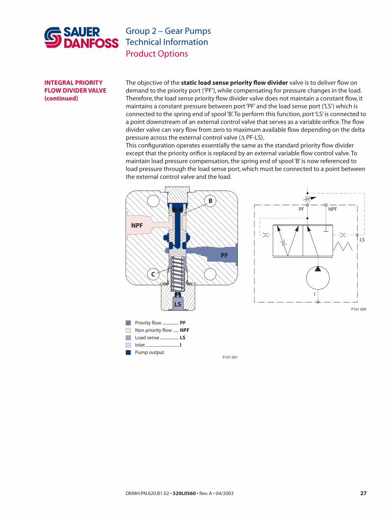
The objective of the static load sense priority flow divider valve is to deliver flow on demand to the priority port (‘PF’), while compensating for pressure changes in the load. Therefore, the load sense priority flow divider valve does not maintain a constant flow, it maintains a constant pressure between port ‘PF’ and the load sense port (‘LS’) which is connected to the spring end of spool ‘B’. To perform this function, port ‘LS’ is connected to a point downstream of an external control valve that serves as a variable orifice. The flow divider valve can vary flow from zero to maximum available flow depending on the delta pressure across the external control valve (∆ PF-LS).This configuration operates essentially the same as the standard priority flow divider except that the priority orifice is replaced by an external variable flow control valve. To maintain load pressure compensation, the spring end of spool ‘B’ is now referenced to load pressure through the load sense port, which must be connected to a point between the external control valve and the load.
Product Options
INTEGRAL PRIORITY FLOW DIVIDER VALVE (continued)
PF
B
C
Pump output
Load sense ................. LS
Inlet ............................... I
NPF
P101 007
Priority flow ............... PF
Non priority flow ..... NPF
LS
PF NPF
LS
I
P101 009
28 DKMH.PN.620.B1.02 • 520L0560 • Rev. A • 04/2003 29DKMH.PN.620.B1.02 • 520L0560 • Rev. A • 04/2003
Group 2 – Gear PumpsTechnical Information
Group 2 – Gear PumpsTechnical Information
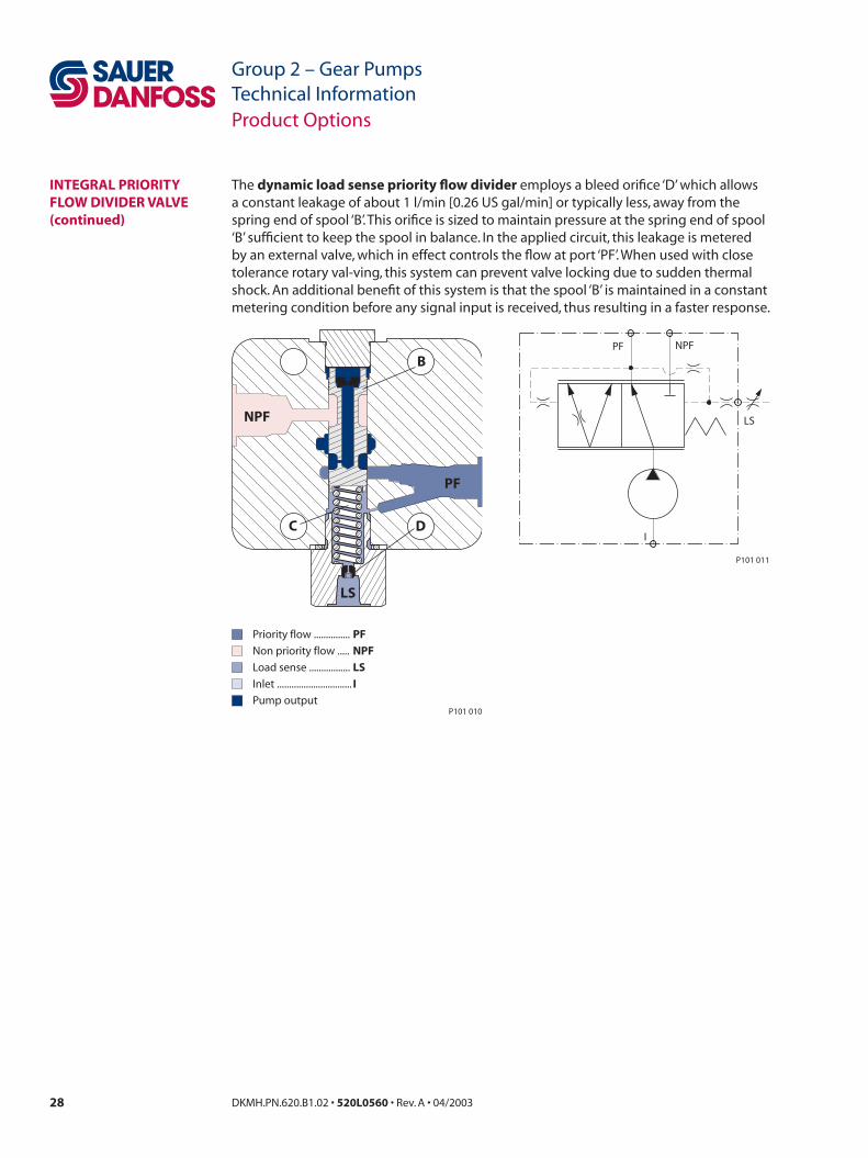
The dynamic load sense priority flow divider employs a bleed orifice ‘D’ which allows a constant leakage of about 1 l/min [0.26 US gal/min] or typically less, away from the spring end of spool ‘B’. This orifice is sized to maintain pressure at the spring end of spool ‘B’ sufficient to keep the spool in balance. In the applied circuit, this leakage is metered by an external valve, which in effect controls the flow at port ‘PF’. When used with close tolerance rotary val-ving, this system can prevent valve locking due to sudden thermal shock. An additional benefit of this system is that the spool ‘B’ is maintained in a constant metering condition before any signal input is received, thus resulting in a faster response.
Product Options
INTEGRAL PRIORITY FLOW DIVIDER VALVE (continued)
PF
B
C D
Pump output
Load sense ................. LS
Inlet ............................... I
NPF
P101 010
Priority flow ............... PF
Non priority flow ..... NPF
LS
PF NPF
LS
I
P101 011
28 DKMH.PN.620.B1.02 • 520L0560 • Rev. A • 04/2003 29DKMH.PN.620.B1.02 • 520L0560 • Rev. A • 04/2003
Group 2 – Gear PumpsTechnical Information
Group 2 – Gear PumpsTechnical Information
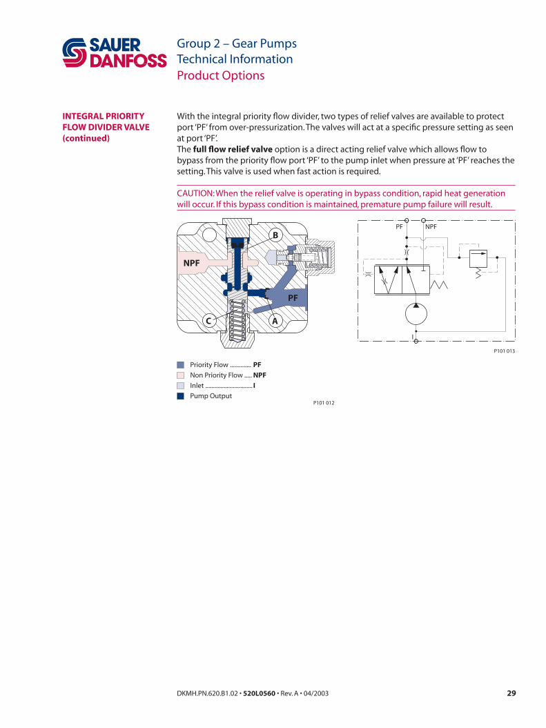
With the integral priority flow divider, two types of relief valves are available to protect port ‘PF’ from over-pressurization. The valves will act at a specific pressure setting as seen at port ‘PF’.The full flow relief valve option is a direct acting relief valve which allows flow to bypass from the priority flow port ‘PF’ to the pump inlet when pressure at ‘PF’ reaches the setting. This valve is used when fast action is required.
CAUTION: When the relief valve is operating in bypass condition, rapid heat generation will occur. If this bypass condition is maintained, premature pump failure will result.
Product Options
INTEGRAL PRIORITY FLOW DIVIDER VALVE (continued)
PF
B
C A
NPF
Priority Flow .............. PF
Pump Output
Non Priority Flow ..... NPF
Inlet ............................... I
P101 012
PF NPF
I
P101 013

30 DKMH.PN.620.B1.02 • 520L0560 • Rev. A • 04/2003 31DKMH.PN.620.B1.02 • 520L0560 • Rev. A • 04/2003
Group 2 – Gear PumpsTechnical Information
Group 2 – Gear PumpsTechnical Information
The pilot relief valve option opens to relieve the pilot pressure from the spring end of spool ‘B’ when the setting is reached. This causes the spool to shift and direct all flow to the non-priority port ‘NPF’. It is important to note that the pressure setting of the pilot relief valve is not referenced to port ‘NPF’. It is also important to note that the pilot relief valve option does not relieve port ‘PF’, it only redirects pump flow.When the pilot relief valve is operating, flow at port ‘NPF’ will increase. Additional circuit pressure protection in the ‘NPF’ line may be required in some applications.
Product Options
INTEGRAL PRIORITY FLOW DIVIDER VALVE (continued)
PF
NPF
P101 014
Priority Flow .............. PF
Pump Output
Non Priority Flow ..... NPF
Inlet ............................... I
PF NPF
I
P101 015
30 DKMH.PN.620.B1.02 • 520L0560 • Rev. A • 04/2003 31DKMH.PN.620.B1.02 • 520L0560 • Rev. A • 04/2003
Group 2 – Gear PumpsTechnical Information
Group 2 – Gear PumpsTechnical Information
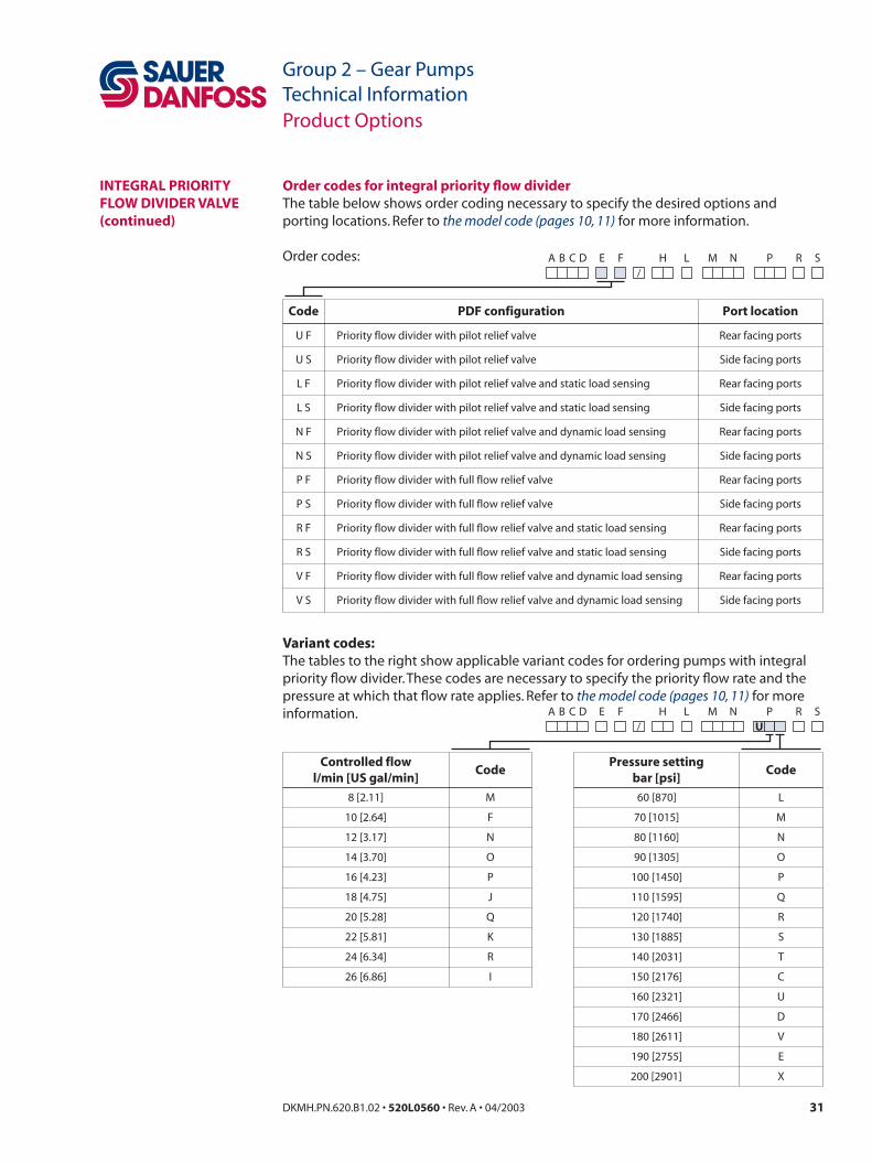
Order codes for integral priority flow dividerThe table below shows order coding necessary to specify the desired options and porting locations. Refer to the model code (pages 10, 11) for more information.
Order codes:
Variant codes:The tables to the right show applicable variant codes for ordering pumps with integral priority flow divider. These codes are necessary to specify the priority flow rate and the pressure at which that flow rate applies. Refer to the model code (pages 10, 11) for more information.
Product Options
INTEGRAL PRIORITY FLOW DIVIDER VALVE (continued)
Code
U F
U S
L F
L S
N F
N S
P F
P S
R F
R S
V F
V S
Port location
Rear facing ports
Side facing ports
Rear facing ports
Side facing ports
Rear facing ports
Side facing ports
Rear facing ports
Side facing ports
Rear facing ports
Side facing ports
Rear facing ports
Side facing ports
PDF configuration
Priority flow divider with pilot relief valve
Priority flow divider with pilot relief valve
Priority flow divider with pilot relief valve and static load sensing
Priority flow divider with pilot relief valve and static load sensing
Priority flow divider with pilot relief valve and dynamic load sensing
Priority flow divider with pilot relief valve and dynamic load sensing
Priority flow divider with full flow relief valve
Priority flow divider with full flow relief valve
Priority flow divider with full flow relief valve and static load sensing
Priority flow divider with full flow relief valve and static load sensing
Priority flow divider with full flow relief valve and dynamic load sensing
Priority flow divider with full flow relief valve and dynamic load sensing
E F/
SA B C D H L M N P R
10 [2.64]
12 [3.17]
14 [3.70]
16 [4.23]
18 [4.75]
20 [5.28]
22 [5.81]
24 [6.34]
26 [6.86]
F
N
O
P
J
Q
K
R
I
M
N
O
P
Q
R
S
T
C
U
D
V
E
X
70 [1015]
80 [1160]
90 [1305]
100 [1450]
110 [1595]
120 [1740]
130 [1885]
140 [2031]
150 [2176]
160 [2321]
170 [2466]
180 [2611]
190 [2755]
200 [2901]
Pressure settingbar [psi]
CodeControlled flow
l/min [US gal/min]Code
8 [2.11] M L60 [870]
E F/
SA B C D H L M N P RU
32 DKMH.PN.620.B1.02 • 520L0560 • Rev. A • 04/2003 33DKMH.PN.620.B1.02 • 520L0560 • Rev. A • 04/2003
Group 2 – Gear PumpsTechnical Information
Group 2 – Gear PumpsTechnical Information
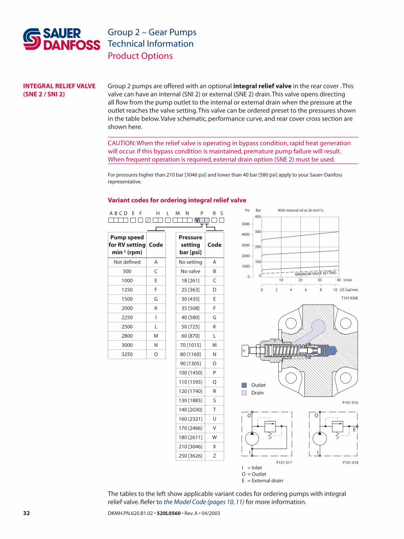
Group 2 pumps are offered with an optional integral relief valve in the rear cover . This valve can have an internal (SNI 2) or external (SNE 2) drain. This valve opens directing all flow from the pump outlet to the internal or external drain when the pressure at the outlet reaches the valve setting. This valve can be ordered preset to the pressures shown in the table below. Valve schematic, performance curve, and rear cover cross section are shown here.
CAUTION: When the relief valve is operating in bypass condition, rapid heat generation will occur. If this bypass condition is maintained, premature pump failure will result. When frequent operation is required, external drain option (SNE 2) must be used.
For pressures higher than 210 bar [3046 psi] and lower than 40 bar [580 psi] apply to your Sauer-Danfoss representative.
Variant codes for ordering integral relief valve
The tables to the left show applicable variant codes for ordering pumps with integral relief valve. Refer to the Model Code (pages 10, 11) for more information.
Product Options
INTEGRAL RELIEF VALVE (SNE 2 / SNI 2)
Bar
0
1000
2000
3000
4000
5000
Psi
l/min
0 US Gal/min
0
100
200
300
400
With mineral oil at 26 mm2/s
T101 030E
10 3020 40
102 4 6 8
MINIMUM VALVE SETTING
Outlet
Drain
P101 016
I
O
P101 017
I I
O
E
P101 018
I = InletO = OutletE = External drain
E F/
SA B C D H L M N P RV
500
1000
1250
1500
2000
2250
2500
2800
3000
C
E
F
G
K
I
L
M
N
3250 O
B
C
D
E
F
G
K
L
M
N
O
P
Q
R
No valve
18 [261]
25 [363]
30 [435]
35 [508]
40 [580]
50 [725]
60 [870]
70 [1015]
80 [1160]
90 [1305]
100 [1450]
110 [1595]
120 [1740]
S
T
U
V
W
X
Z
130 [1885]
140 [2030]
160 [2321]
170 [2466]
180 [2611]
210 [3046]
250 [3626]
Pressuresetting
bar [psi]Code
Pump speedfor RV setting
min-1 (rpm)Code
Not defined A ANo setting
32 DKMH.PN.620.B1.02 • 520L0560 • Rev. A • 04/2003 33DKMH.PN.620.B1.02 • 520L0560 • Rev. A • 04/2003
Group 2 – Gear PumpsTechnical Information
Group 2 – Gear PumpsTechnical Information
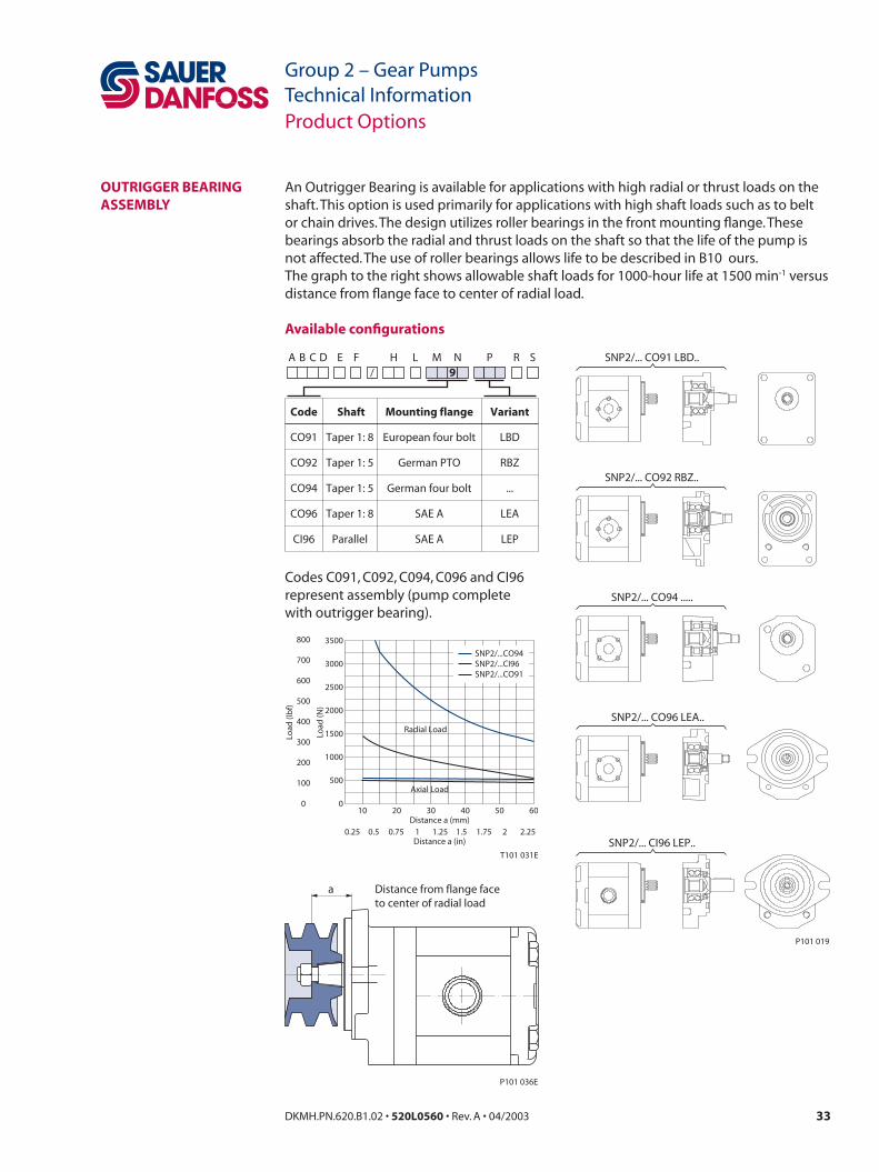
An Outrigger Bearing is available for applications with high radial or thrust loads on the shaft. This option is used primarily for applications with high shaft loads such as to belt or chain drives. The design utilizes roller bearings in the front mounting flange. These bearings absorb the radial and thrust loads on the shaft so that the life of the pump is not affected. The use of roller bearings allows life to be described in B10 ours.The graph to the right shows allowable shaft loads for 1000-hour life at 1500 min-1 versus distance from flange face to center of radial load.
Available configurations
Product Options
OUTRIGGER BEARING ASSEMBLY
T101 031E
0
500
1000
1500
2000
2500
3000
3500
10 20 30 40 50 60
Radial Load
Axial Load
SNP2/...CO94SNP2/...CI96SNP2/...CO91
0.25 0.5 0.75 1 1.25 1.5 1.75 2 2.25Distance a (mm)
Distance a (in)
Load
(N)
Load
(lb
f)
0
100
200
300
400
500
600
700
800
P101 036E
Distance from flange faceto center of radial load
a
SNP2/... CO91 LBD..
SNP2/... CO94 .....
SNP2/... CO92 RBZ..
SNP2/... CO96 LEA..
SNP2/... CI96 LEP..
P101 019
Code
CO91
CO92
Shaft
Taper 1: 8
Taper 1: 5
Mounting flange
European four bolt
German PTO
Variant
LBD
RBZ
CO94 Taper 1: 5 German four bolt ...
CO96
CI96
Taper 1: 8
Parallel
SAE A
SAE A
LEA
LEP
E F/
SA B C D H L M N P R9
Codes C091, C092, C094, C096 and CI96 represent assembly (pump complete with outrigger bearing).
34 DKMH.PN.620.B1.02 • 520L0560 • Rev. A • 04/2003 35DKMH.PN.620.B1.02 • 520L0560 • Rev. A • 04/2003
Group 2 – Gear PumpsTechnical Information
Group 2 – Gear PumpsTechnical Information
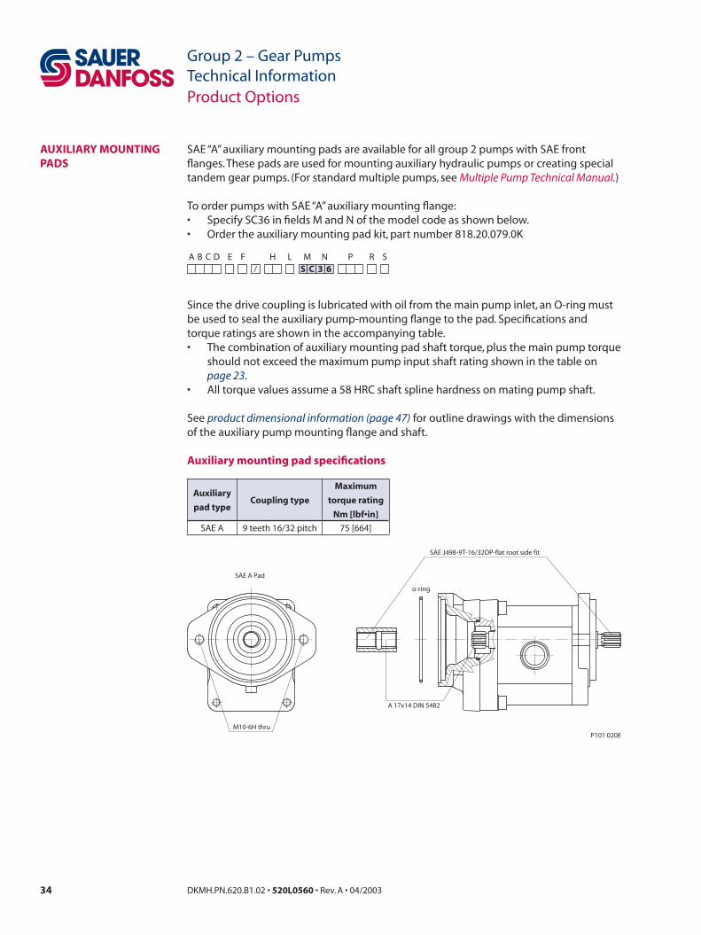
SAE “A” auxiliary mounting pads are available for all group 2 pumps with SAE front flanges. These pads are used for mounting auxiliary hydraulic pumps or creating special tandem gear pumps. (For standard multiple pumps, see Multiple Pump Technical Manual.)
To order pumps with SAE “A” auxiliary mounting flange:• Specify SC36 in fields M and N of the model code as shown below.• Order the auxiliary mounting pad kit, part number 818.20.079.0K
Since the drive coupling is lubricated with oil from the main pump inlet, an O-ring must be used to seal the auxiliary pump-mounting flange to the pad. Specifications and torque ratings are shown in the accompanying table.• The combination of auxiliary mounting pad shaft torque, plus the main pump torque
should not exceed the maximum pump input shaft rating shown in the table on page 23.
• All torque values assume a 58 HRC shaft spline hardness on mating pump shaft.
See product dimensional information (page 47) for outline drawings with the dimensions of the auxiliary pump mounting flange and shaft.
Auxiliary mounting pad specifications
Product Options
AUXILIARY MOUNTING PADS
SAE A Pad
SAE J498-9T-16/32DP-flat root side fit
A 17x14 DIN 5482
o-ring
M10-6H thruP101 020E
E F/
SA B C D H L M N P RS C 3 6
Auxiliary
pad typeCoupling type
Maximum
torque rating
Nm [lbf•in]
SAE A 9 teeth 16/32 pitch 75 [664]

34 DKMH.PN.620.B1.02 • 520L0560 • Rev. A • 04/2003 35DKMH.PN.620.B1.02 • 520L0560 • Rev. A • 04/2003
Group 2 – Gear PumpsTechnical Information
Group 2 – Gear PumpsTechnical Information
Standard porting and rear cover shown. See page 43 for additional porting options.See page 44 for valve options. See page 45 for outrigger bearing options.
Product Dimensional Information
SC01 / CI01 / CO01
[0.3
74
]+
0.15
+0.
006
-0.2
5-0
.010
[1.4
38
]
-0.0
25-0
.064
+0.
001
-0.0
03
9 [3.55]
nut and washersupplied with pump
[0.6
19
]
A
A
[0.6
50
]
(min full thd 12mm [0.472] deep)
1 : 8
Section: A-A
M12
x1.2
5-6g
E/e
40.5 [1.596]
Ø 1
7.46
[0.6
87]
6.3 [0.248] 21.7 [0.854]
17 [0.670]
B max
18 [0.709] 5 [0.020]
C/c
M6
Thre
ad
16m
m [.
630]
dee
p
Section: B-B
B
B
6.5 [0.256]
30 [1.182]
36.5 [1.438]
Splin
e
B17
x14
DIN
548
2
pro
file
off
set
+0.
6 [0
.024
]
6.5 [0.256]
10 [0.394]
19.5 [0.768]
body width
(96.
2 [3
.790
])
115.
2 [4
.539
] max
90 [3.546] max
D/d ±0.20 [0.008]
A ±0.50 [0.020]
(41.
9 [1
.651
])
71.5[2.817]
63.8
[2.5
14]
32.4
[1.2
77]
(73.
3 [2
.888
])
90 [3.546 ]±0.25 ±0.010
15.7
±0.
50±
0.02
0
4 0 0-0.030 [0.158 ]-0.001
9.5
Ø 1
6.5
[
0.65
0
]0 -0
.110
0 -0.0
04
Ø 3
6.5
16.5
+0.
10-0
.20
+0.
004
-0.0
08Ø
15
[0
.591
]
0 -0.0
180 -0.0
01
4 0-0.030
0-0.001[0.158 ]
X
Ø 0.75 [0.030] X
P101 021E
SC01 CI01 CO01
Type (displacement) 4 6 8 11 14 17 19 22 25
Dimensions
A*43.25
[1.703]
45
[1.772]
45
[1.772]
49
[1.929]
52
[2.047]
52
[2.047]
56
[2.205]
59
[2.323]
59
[2.323]
B**90.0
[3.543]
93.0
[3.681]
97.5
[3.839]
101.5
[3.996]
107.5
[4.232]
111.5
[4.390]
115.5
[4.574]
121.5
[4.783]
125.5
[4.941]
Inlet
C13.5
[0.531]
13.5
[0.531]
13.5
[0.531]
13.5
[0.531]
20
[0.787]
20
[0.787]
20
[0.787]
20
[0.787]
20
[0.787]
D30
[1.181]
30
[1.181]
30
[1.181]
30
[1.181]
40
[1.575]
40
[1.575]
40
[1.575]
40
[1.575]
40
[1.575]
E M6 M6 M6 M6 M8 M8 M8 M8 M8
Outlet
c13.5
[0.531]
13.5
[0.531]
13.5
[0.531]
13.5
[0.531]
13.5
[0.531]
13.5
[0.531]
13.5
[0.531]
13.5
[0.531]
20
[0.787]
d30
[1.181]
30
[1.181]
30
[1.181]
30
[1.181]
30
[1.181]
30
[1.181]
30
[1.181]
30
[1.181]
40
[1.575]
e M6 M6 M6 M6 M6 M6 M6 M6 M8
* Add 3 mm [0.118 in] for SHP 2 pumps.** Add 6 mm [0.236 in] for SHP 2 pumps.

36 DKMH.PN.620.B1.02 • 520L0560 • Rev. A • 04/2003 37DKMH.PN.620.B1.02 • 520L0560 • Rev. A • 04/2003
Group 2 – Gear PumpsTechnical Information
Group 2 – Gear PumpsTechnical Information
Standard porting and rear cover shown. See page 43 for additional porting options.See page 44 for valve options.
Product Dimensional Information
SC02 / CO02
3 [0.118 ]
Ø 8
0
[3.1
50
]
9 [0.354]
Ø 1
6.5
[
0.65
0
]
splineB17x14 DIN 5482profile offset +0.6 [.024]
13.5 [0.531]
23.5 [0.952]
1 : 5
A
Section: A-A
A
M12
x1.2
5-6g
16.5 [0.650]
E/e
17.4
6[0
.687
]
38 [1.496]B max
12.5 [0.492] 7.2 [0.283]
5.7 [0.224] 19.3 [0.760]
C/c
45˚
body width
(100
[3.9
37])
D/d ±0.20 [0.008]
A ±0.50
72[2.835]
120
[4.7
24] m
ax
92 [3.622] max
(44.
5 [1
.72]
)
65.5
[2.5
79]
34.5
[1.3
58]
(75.
5 [2
.972
])
90 ±0.25 ±0.0103.543[ ]
0 -0.1
100 -0
.004
+0.
060
-0.1
0 6+
0.00
2-0
.004
0-0.025
0-0.001
9
[0.3
54
]+
0.30
-0.1
0+
0.01
2-0
.004
15.7
[
0.61
8
]±
0.50
+0.
020
Ø 0.75 [0.030] X
X
(min full thd 12 mm [0.472] deep)
nut and washer supplied with pump
P101 022E
SC02 CO02
Type (displacement) 4 6 8 11 14 17 19 22 25
Dimensions
A*39.8
[1.567]
41.1
[1.618]
43.1
[1.697]
47.5
[1.870]
47.5
[1.870]
47.5
[1.870]
47.5
[1.870]
55
[2.165]
64.5
[2.539]
B**92.5
[3.642]
96
[3.780]
100
[3.937]
104
[4.094]
110
[4.331]
114
[4.488]
118
[4.646]
124
[4.882]
128
[5.039]
Inlet
C15
[0.591]
15
[0.591]
20
[0.787]
20
[0.787]
20
[0.787]
20
[0.787]
20
[0.787]
20
[0.787]
20
[0.787]
D 40 [1.575]
E M6
Outlet
c 15 [0.591]
d 35 [1.378]
e M6
* Add 3 mm [0.118 in] for SHP 2 pumps.** Add 6 mm [0.236 in] for SHP 2 pumps.
36 DKMH.PN.620.B1.02 • 520L0560 • Rev. A • 04/2003 37DKMH.PN.620.B1.02 • 520L0560 • Rev. A • 04/2003
Group 2 – Gear PumpsTechnical Information
Group 2 – Gear PumpsTechnical Information
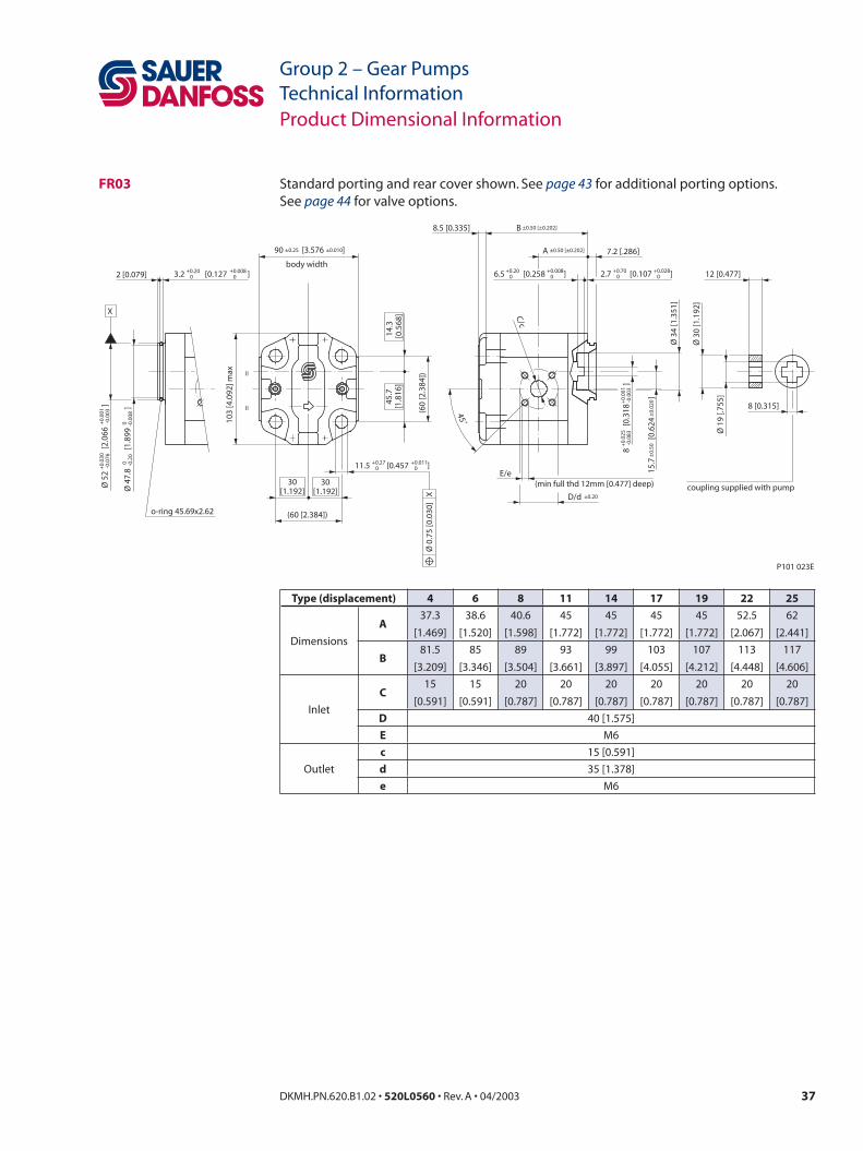
Standard porting and rear cover shown. See page 43 for additional porting options.See page 44 for valve options.
Product Dimensional Information
FR03
3.2 [0.127 ]+0.200
+0.00802 [0.079]
(min full thd 12mm [0.477] deep)E/e
Ø 3
4 [1
.351
]
7.2 [.286]
Ø 1
9 [.7
55]
Ø 3
0 [1
.192
]
12 [0.477]
C/c
45˚
X
o-ring 45.69x2.62
==
body width
(60
[2.3
84])
D/d ±0.20
B8.5 [0.335] ±0.50 [±0.202]
A
(60 [2.384])
103
[4.0
92] m
ax
30[1.192]
45.7
[1.8
16]
14.3
[0.5
68]
30[1.192]
Ø 5
2
[2.
066
]
+0.
030
-0.0
76+
0.00
1-0
.003
8
[0.
318
]
+0.
025
-0.0
83+
0.00
1-0
.003
11.5 [0.457 ]+0.270
+0.0110
2.7 [0.107 ]+0.700
+0.02806.5 [0.258 ]+0.20
0+0.008
0
Ø 4
7.8
[1
.899
]
0 -0.2
00 -0
.008
15.7
[0
.624
]
±0.
50±
0.02
0
90 [3.576 ]±0.25 ±0.010
Ø 0
.75
[0.0
30]
X
8 [0.315]
coupling supplied with pump
P101 023E
±0.50 [±0.202]
Type (displacement) 4 6 8 11 14 17 19 22 25
Dimensions
A37.3
[1.469]
38.6
[1.520]
40.6
[1.598]
45
[1.772]
45
[1.772]
45
[1.772]
45
[1.772]
52.5
[2.067]
62
[2.441]
B81.5
[3.209]
85
[3.346]
89
[3.504]
93
[3.661]
99
[3.897]
103
[4.055]
107
[4.212]
113
[4.448]
117
[4.606]
Inlet
C15
[0.591]
15
[0.591]
20
[0.787]
20
[0.787]
20
[0.787]
20
[0.787]
20
[0.787]
20
[0.787]
20
[0.787]
D 40 [1.575]
E M6
Outlet
c 15 [0.591]
d 35 [1.378]
e M6
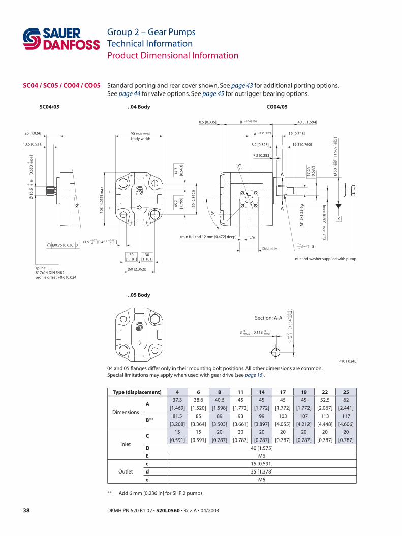
38 DKMH.PN.620.B1.02 • 520L0560 • Rev. A • 04/2003 39DKMH.PN.620.B1.02 • 520L0560 • Rev. A • 04/2003
Group 2 – Gear PumpsTechnical Information
Group 2 – Gear PumpsTechnical Information
Standard porting and rear cover shown. See page 43 for additional porting options.See page 44 for valve options. See page 45 for outrigger bearing options.
04 and 05 flanges differ only in their mounting bolt positions. All other dimensions are common.Special limitations may apply when used with gear drive (see page 16).
Product Dimensional Information
SC04 / SC05 / CO04 / CO05
3 [0.118 ]
11.5 [0.453 ]
Ø 1
6.5
[0.
650
]
±0.
50±
0.00
1
A ±0.50 [.020]
B8.5 [0.335] ±0.50 [.020]
+0.270
+0.0110
splineB17x14 DIN 5482profile offset +0.6 [0.024]
13.5 [0.531]
26 [1.024]
Section: A-A
A
A
1 : 5
X
(min full thd 12 mm [0.472] deep)
M12
x1.2
5-6g
17.4
6[0
.687
]
19 [0.748]
E/e
7.2 [0.283]
40.5 [1.594]
8.2 [0.323] 19.3 [0.760]
C/c
45˚
body width
== (6
0 [2
.362
])
D/d ±0.20
90 ±0.25 [0.010]
(60 [2.362])
103
[4.0
55] m
ax
45.7
[1.7
99]
14.3
[0.5
63]
30[1.181]
30[1.181]
Ø0.75 [0.030] X
0 -0.1
100 -0
.004
+0.
025
-0.0
64Ø
50
[1.9
69
]+
0.00
1-0
.003
+0.
30-0
.10
9
[0
.354
]
+0.
012
-0.0
04
0-0.025
0-0.001
nut and washer supplied with pump
P101 024E
SC04/05 ..04 Body
..05 Body
CO04/05
15.7
[
0.61
8
]
Type (displacement) 4 6 8 11 14 17 19 22 25
Dimensions
A37.3
[1.469]
38.6
[1.520]
40.6
[1.598]
45
[1.772]
45
[1.772]
45
[1.772]
45
[1.772]
52.5
[2.067]
62
[2.441]
B**81.5
[3.208]
85
[3.364]
89
[3.503]
93
[3.661]
99
[3.897]
103
[4.055]
107
[4.212]
113
[4.448]
117
[4.606]
Inlet
C15
[0.591]
15
[0.591]
20
[0.787]
20
[0.787]
20
[0.787]
20
[0.787]
20
[0.787]
20
[0.787]
20
[0.787]
D 40 [1.575]
E M6
Outlet
c 15 [0.591]
d 35 [1.378]
e M6
** Add 6 mm [0.236 in] for SHP 2 pumps.
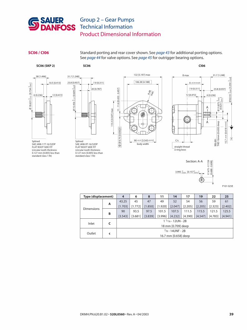
38 DKMH.PN.620.B1.02 • 520L0560 • Rev. A • 04/2003 39DKMH.PN.620.B1.02 • 520L0560 • Rev. A • 04/2003
Group 2 – Gear PumpsTechnical Information
Group 2 – Gear PumpsTechnical Information
Standard porting and rear cover shown. See page 43 for additional porting options.See page 44 for valve options. See page 45 for outrigger bearing options.
Product Dimensional Information
SC06 / CI06
[0.6
25
]TH
D 1
6mm
[0.6
30] d
eep
A
A
Section: A-A
7.9 [0.311] 23.8 [0.937]
B max 31.7 [1.248]
C/c
M6-
6H-
17.4
75 -1
7.72
9[0
.688
- 0.
698]
12 [0.472] 6 [0.236]
body width
11 -
11.6
[0.4
33 -
0.45
7]
A ±0.50 [0.020]
132 [5.197] max
106.38 [4.188]
115.
5 [4
.547
] max
R 48
max
Ø 8
2.55
[3
.250
]
0 -0.0
500 -0.0
20
3.995 [0.157 ]0-0.025
0-0.010
Ø 1
5.87
50 -0
.025
0 -0.0
10
90 [3.543 ]±0.25 ±0.010
15.7
[0
.618
]
±0.
50±
0.02
0
Ø 0
.75
[0.0
30] X
X
o-ring bossstraight thread
P101 025E
SC06
12 [0.472]6 [0.236]
SplinedSAE J498-11T-16/32DPFLAT ROOT SIDE FIT(circular tooth thickness0.127 mm [0.005] less thanstandard class 1 fit)
38 [1.496]
10.5 [0.413]
Ø 1
8.63
1
[0.7
34
]0 -0
.127
0 -0.0
05
SC06 (SKP 2) CI06
20 [0.787]
31.7 [1.248]
23.8 [0.937] 7.9 [0.311]
Ø 1
5.45
6
[0.6
09
]
0 -0.1
270 -0.0
05
SplinedSAE J498-9T-16/32DPFLAT ROOT SIDE FIT(circular tooth thickness0.127 mm [0.005] less thanstandard class 1 fit)
Type (displacement) 4 6 8 11 14 17 19 22 25
Dimensions
A43.25
[1.703]
45
[1.772]
47
[1.850]
49
[1.920]
52
[2.047]
54
[2.205]
56
[2.205]
59
[2.323]
61
[2.402]
B90
[3.543]
93.5
[3.681]
97.5
[3.839]
101.5
[3.996]
107.5
[4.232]
111.5
[4.390]
115.5
[4.547]
121.5
[4.783]
125.5
[4.941]
Inlet C1 1/16 - 12UN - 2B
18 mm [0.709] deep
Outlet c7/8 - 14UNF - 2B
16.7 mm [0.658] deep

40 DKMH.PN.620.B1.02 • 520L0560 • Rev. A • 04/2003 41DKMH.PN.620.B1.02 • 520L0560 • Rev. A • 04/2003
Group 2 – Gear PumpsTechnical Information
Group 2 – Gear PumpsTechnical Information
Standard porting and rear cover shown. See page 43 for additional porting options.See page 44 for valve options.
Special limitations may apply when used with gear drive (see page 16).
Product Dimensional Information
CO091.7 [0.067 ]
1: 8
B
B
Section: B - B
Ø 1
7.46
[0.6
87]
M12
x1.2
5-6g
21.7 [0.854]
B max
14-15 [0.551-0.591]
9 [0.354]
R 0.8 max
R 10.5 [0.413]
19˚
31.5
[1.2
40]
3/8-
16U
NC
-2B
122.5 [4.823] max
(99.6 [3.921])
103
[4.0
55] m
ax
(69
[2.7
17])
(34
[1.3
39])
19 [0.748]
P101 026E
(R11.45 [0.451] max)
(R 1
1.45
[0.4
51] m
ax)
R 35 [1
.378]
49.2[1.937]
50.4[1.984]
17.2 [0.677 ]
40.5 [1.594 ]±1 ±0.039
4.5 [0.177 ]±0.25 ±0.010
90
[3.5
43
]±
0.25
±0.
010
12.5 [0.492 ]±0.50 ±0.020
6.3 [0.248 ]±0.75 ±0.030
15.7
±0.
50±
.020
[]
.618
9.5 [0.374 ]+0.15 +0.006-0.25 -0.010
+0.15
+0.006
0
0
3
[0.1
18
]0
0-0
.025
-0.0
01
Ø 5
2.34
[2
.061
]
00
-0.0
5-0
.020 Ø
0.7
5 [0
.030
] X
X
E/e
C/c
D/d
A ±0.50 [.020]
(min full thd 12mm [0.472] deep)
±0.75 ±0.030
Type (displacement) 4 6 8 11 14 17 19 22 25
Dimensions
A37.3
[1.469]
38.6
[1.520]
40.6
[1.598]
45
[1.772]
45
[1.772]
45
[1.772]
45
[1.772]
52.5
[2.067]
62
[2.441]
B90
[3.543]
93.5
[3.681]
97.5
[3.839]
101.5
[3.996]
107.5
[4.232]
111.5
[4.390]
115.5
[4.547]
121.5
[4.783]
125.5
[4.941]
Inlet
C15
[0.591]
15
[0.591]
20
[0.787]
20
[0.787]
20
[0.787]
20
[0.787]
20
[0.787]
20
[0.787]
20
[0.787]
D 40 [1.575]
E M6
Outlet
c 15 [0.591]
d 35 [1.378]
e M6
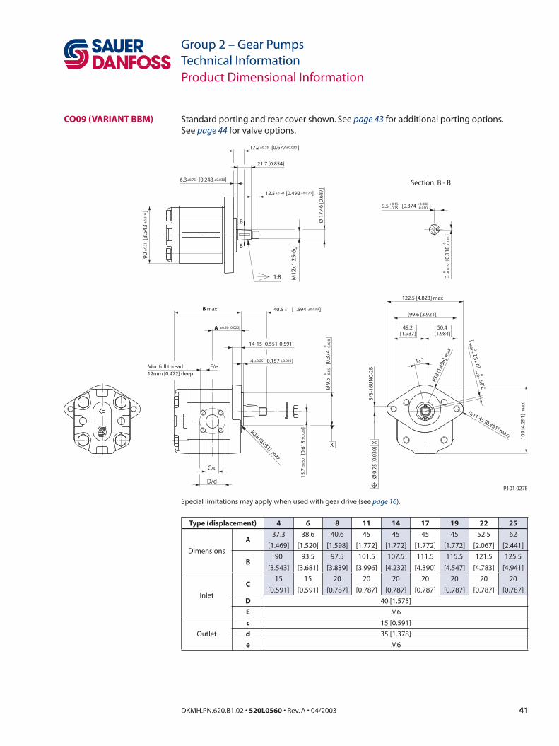
40 DKMH.PN.620.B1.02 • 520L0560 • Rev. A • 04/2003 41DKMH.PN.620.B1.02 • 520L0560 • Rev. A • 04/2003
Group 2 – Gear PumpsTechnical Information
Group 2 – Gear PumpsTechnical Information
Standard porting and rear cover shown. See page 43 for additional porting options.See page 44 for valve options.
Special limitations may apply when used with gear drive (see page 16).
Product Dimensional Information
CO09 (VARIANT BBM)
1:8
B
B
Section: B - B
21.7 [0.854]
M12
x1.2
5-6g
Ø 1
7.46
[0.6
87]
3
[0.
118
]0
0-0
.025
-0.0
01
9.5 [0.374 ]+0.15 +0.006-0.25 -0.010
90
[3.5
43
]±
0.25
±0.
010
6.3 [0.248 ]
17.2 [0.677 ]±0.75 ±0.030
12.5 [0.492 ]±0.50 ±0.020
B max
R0.8 [0.031] max
14-15 [0.551-0.591]
3/8-
16U
NC
-2B
(99.6 [3.921])
122.5 [4.823] max
P101 027E
109
[4.2
91] m
ax
R38
[1.4
96] m
ax
(R11.45 [0.451] max)
13˚
50.4[1.984]
49.2[1.937]
3.85
[0
.152
]
+0.
15+
0.00
6
0
0
Ø 9
.5
[0.
374
]
00
-0.0
5-0
.020
15.7
[
0.61
8
]±
0.50
±0.
020
4 [0.157 ]±0.25 ±0.010
40.5 [1.594 ]±1 ±0.039
X
Ø 0
.75
[0.0
30]
XMin. full thread12mm [0.472] deep
E/e
C/c
D/d
A ±0.50 [0.020]
±0.75 ±0.030
Type (displacement) 4 6 8 11 14 17 19 22 25
Dimensions
A37.3
[1.469]
38.6
[1.520]
40.6
[1.598]
45
[1.772]
45
[1.772]
45
[1.772]
45
[1.772]
52.5
[2.067]
62
[2.441]
B90
[3.543]
93.5
[3.681]
97.5
[3.839]
101.5
[3.996]
107.5
[4.232]
111.5
[4.390]
115.5
[4.547]
121.5
[4.783]
125.5
[4.941]
Inlet
C15
[0.591]
15
[0.591]
20
[0.787]
20
[0.787]
20
[0.787]
20
[0.787]
20
[0.787]
20
[0.787]
20
[0.787]
D 40 [1.575]
E M6
Outlet
c 15 [0.591]
d 35 [1.378]
e M6
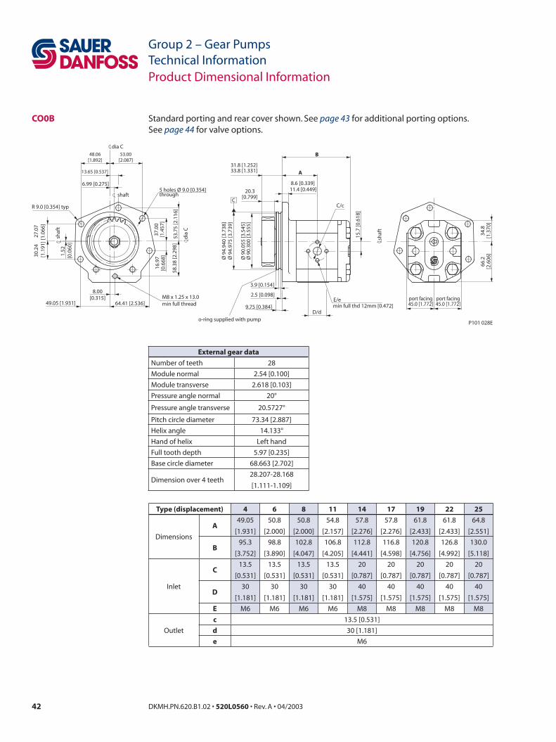
42 DKMH.PN.620.B1.02 • 520L0560 • Rev. A • 04/2003 43DKMH.PN.620.B1.02 • 520L0560 • Rev. A • 04/2003
Group 2 – Gear PumpsTechnical Information
Group 2 – Gear PumpsTechnical Information
Standard porting and rear cover shown. See page 43 for additional porting options.See page 44 for valve options.
Product Dimensional Information
CO0B
34.8
[1.3
70]
66.2
[2.6
06]
port facing45.0 [1.772] 45.0 [1.772]
C
shaf
t
dia C
3.9 [0.154]
2.5 [0.098]
A
20.3[0.799]
9.75 [0.384]
B
15.7
[0.6
18]
min full thread
shaft
shaf
t
dia
C
through
1.52
[0.0
60]
6.99 [0.275]
58.3
8 [2
.298
]
16.9
7[0
.668
]37
.00
[1.4
57]
53.7
5 [2
.116
]
27.0
7[1
.066
]
64.41 [2.536]
48.06[1.892]
49.05 [1.931]
8.00[0.315]
53.00[2.087]
13.65 [0.537]
30.2
4[1
.191
]
M8 x 1.25 x 13.0
R 9.0 [0.354] typ
5 holes Ø 9.0 [0.354]
33.8 [1.331]31.8 [1.252]
11.4 [0.449]8.6 [0.339]
C/c
D/d
E/emin full thd 12mm [0.472]
Ø 9
4.94
0 [3
.738
]Ø
94.
975
[3.7
39]
Ø 9
0.05
5 [3
.545
]Ø
90.
300
[3.5
55]
o-ring supplied with pumpP101 028E
port facing
External gear data
Number of teeth 28
Module normal 2.54 [0.100]
Module transverse 2.618 [0.103]
Pressure angle normal 20°
Pressure angle transverse 20.5727°
Pitch circle diameter 73.34 [2.887]
Helix angle 14.133°
Hand of helix Left hand
Full tooth depth 5.97 [0.235]
Base circle diameter 68.663 [2.702]
Dimension over 4 teeth28.207-28.168
[1.111-1.109]
Type (displacement) 4 6 8 11 14 17 19 22 25
Dimensions
A49.05
[1.931]
50.8
[2.000]
50.8
[2.000]
54.8
[2.157]
57.8
[2.276]
57.8
[2.276]
61.8
[2.433]
61.8
[2.433]
64.8
[2.551]
B95.3
[3.752]
98.8
[3.890]
102.8
[4.047]
106.8
[4.205]
112.8
[4.441]
116.8
[4.598]
120.8
[4.756]
126.8
[4.992]
130.0
[5.118]
Inlet
C13.5
[0.531]
13.5
[0.531]
13.5
[0.531]
13.5
[0.531]
20
[0.787]
20
[0.787]
20
[0.787]
20
[0.787]
20
[0.787]
D30
[1.181]
30
[1.181]
30
[1.181]
30
[1.181]
40
[1.575]
40
[1.575]
40
[1.575]
40
[1.575]
40
[1.575]
E M6 M6 M6 M6 M8 M8 M8 M8 M8
Outlet
c 13.5 [0.531]
d 30 [1.181]
e M6
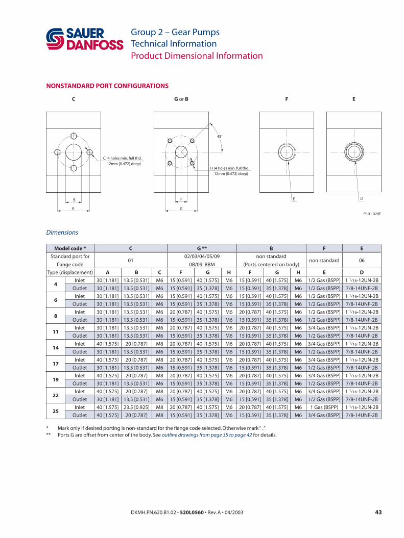
42 DKMH.PN.620.B1.02 • 520L0560 • Rev. A • 04/2003 43DKMH.PN.620.B1.02 • 520L0560 • Rev. A • 04/2003
Group 2 – Gear PumpsTechnical Information
Group 2 – Gear PumpsTechnical InformationProduct Dimensional Information
NONSTANDARD PORT CONFIGURATIONS
E DF
G
45˚
H (4 holes min. full thd.
12mm [0.472] deep)
B
A
C (4 holes min. full thd.
12mm [0.472] deep)
P101 029E
C G or B F E
Dimensions
Model code * C G ** B F E
Standard port for
flange code01
02/03/04/05/09
0B/09..BBM
non standard
(Ports centered on body)non standard 06
Type (displacement) A B C F G H F G H E D
4Inlet 30 [1.181] 13.5 [0.531] M6 15 [0.591] 40 [1.575] M6 15 [0.591] 40 [1.575] M6 1/2 Gas (BSPP) 1 1/16-12UN-2B
Outlet 30 [1.181] 13.5 [0.531] M6 15 [0.591] 35 [1.378] M6 15 [0.591] 35 [1.378] M6 1/2 Gas (BSPP) 7/8-14UNF-2B
6Inlet 30 [1.181] 13.5 [0.531] M6 15 [0.591] 40 [1.575] M6 15 [0.591] 40 [1.575] M6 1/2 Gas (BSPP) 1 1/16-12UN-2B
Outlet 30 [1.181] 13.5 [0.531] M6 15 [0.591] 35 [1.378] M6 15 [0.591] 35 [1.378] M6 1/2 Gas (BSPP) 7/8-14UNF-2B
8Inlet 30 [1.181] 13.5 [0.531] M6 20 [0.787] 40 [1.575] M6 20 [0.787] 40 [1.575] M6 1/2 Gas (BSPP) 1 1/16-12UN-2B
Outlet 30 [1.181] 13.5 [0.531] M6 15 [0.591] 35 [1.378] M6 15 [0.591] 35 [1.378] M6 1/2 Gas (BSPP) 7/8-14UNF-2B
11Inlet 30 [1.181] 13.5 [0.531] M6 20 [0.787] 40 [1.575] M6 20 [0.787] 40 [1.575] M6 3/4 Gas (BSPP) 1 1/16-12UN-2B
Outlet 30 [1.181] 13.5 [0.531] M6 15 [0.591] 35 [1.378] M6 15 [0.591] 35 [1.378] M6 1/2 Gas (BSPP) 7/8-14UNF-2B
14Inlet 40 [1.575] 20 [0.787] M8 20 [0.787] 40 [1.575] M6 20 [0.787] 40 [1.575] M6 3/4 Gas (BSPP) 1 1/16-12UN-2B
Outlet 30 [1.181] 13.5 [0.531] M6 15 [0.591] 35 [1.378] M6 15 [0.591] 35 [1.378] M6 1/2 Gas (BSPP) 7/8-14UNF-2B
17Inlet 40 [1.575] 20 [0.787] M8 20 [0.787] 40 [1.575] M6 20 [0.787] 40 [1.575] M6 3/4 Gas (BSPP) 1 1/16-12UN-2B
Outlet 30 [1.181] 13.5 [0.531] M6 15 [0.591] 35 [1.378] M6 15 [0.591] 35 [1.378] M6 1/2 Gas (BSPP) 7/8-14UNF-2B
19Inlet 40 [1.575] 20 [0.787] M8 20 [0.787] 40 [1.575] M6 20 [0.787] 40 [1.575] M6 3/4 Gas (BSPP) 1 1/16-12UN-2B
Outlet 30 [1.181] 13.5 [0.531] M6 15 [0.591] 35 [1.378] M6 15 [0.591] 35 [1.378] M6 1/2 Gas (BSPP) 7/8-14UNF-2B
22Inlet 40 [1.575] 20 [0.787] M8 20 [0.787] 40 [1.575] M6 20 [0.787] 40 [1.575] M6 3/4 Gas (BSPP) 1 1/16-12UN-2B
Outlet 30 [1.181] 13.5 [0.531] M6 15 [0.591] 35 [1.378] M6 15 [0.591] 35 [1.378] M6 1/2 Gas (BSPP) 7/8-14UNF-2B
25Inlet 40 [1.575] 23.5 [0.925] M8 20 [0.787] 40 [1.575] M6 20 [0.787] 40 [1.575] M6 1 Gas (BSPP) 1 1/16-12UN-2B
Outlet 40 [1.575] 20 [0.787] M8 15 [0.591] 35 [1.378] M6 15 [0.591] 35 [1.378] M6 3/4 Gas (BSPP) 7/8-14UNF-2B
* Mark only if desired porting is non-standard for the flange code selected. Otherwise mark “ . “** Ports G are offset from center of the body. See outline drawings from page 35 to page 42 for details.

44 DKMH.PN.620.B1.02 • 520L0560 • Rev. A • 04/2003 45DKMH.PN.620.B1.02 • 520L0560 • Rev. A • 04/2003
Group 2 – Gear PumpsTechnical Information
Group 2 – Gear PumpsTechnical Information
Product Dimensional Information
INTEGRAL PRIORITY FLOW DIVIDER COVER AND INTEGRAL RELIEF VALVE COVER
94.1
5 [3
.707
]93
.25
[3.6
71]
25.1
7 [0
.991
]23
.87
[0.9
40]
26.0
5 [1
.026
]25
.15
[0.9
90]
VIEW WITHNO RELIEF
VALVE SHOWN
15.0
0 [0
.591
]14
.40
[0.5
67]
66.05 [2.600]64.95 [2.557]
91 [3.583]
65.5 [2.579]
50.30 [1.980]49.70 [1.957]
23.50[0.925]
Position ofoptional full
flow relief valve
SHAFT
Ø34
.0 [1
.334
]
88.8 [3.496]
80.3
0 [3
.161
]79
.10
[3.1
14]
27.5[1.083]
SHAFT39.4
0 [1
.551
]38
.20
[1.5
04]
2 alternativeswith or withoutload sense ports
AX
IAL RA
DIA
L
2 alternativesnon priority
port positions
RADIAL
AXIAL
2 alternativepriority port
positions
WITH WIT
HO
UT
Optional pilotrelief valve
7/16"-20UNF(standard for SAEflanged pumps)
63.77 [2.511]51.90 [2.043]51.10 [2.011]
31.0[1.220]
15.7
0[0
.618
]
A
RAD
IALA
XIAL
P101 030E
41.5 [1.634] max A
SHAFT
DRAIN (SNE only)3/4-16 UNF-2B o-ring boss(standard for SAE flanged pumps)
93 [3.661] max
10.8
[0.4
25]
P101 031E
Dimensions
Type (displacement) 4 6 8 11 14 17 19 22 25
SNP2 / SKP2 A*68
[2.697]
72
[2.835]
76
[2.992]
80
[3.150]
86
[3.386]
90
[3.543]
94
[3.701]
100
[3.937]
104
[4.094]
SHP2 A100
[3.937]
106
[4.173]
110
[4.331]
* For 02 flange add 2.5 mm [0.098 in]
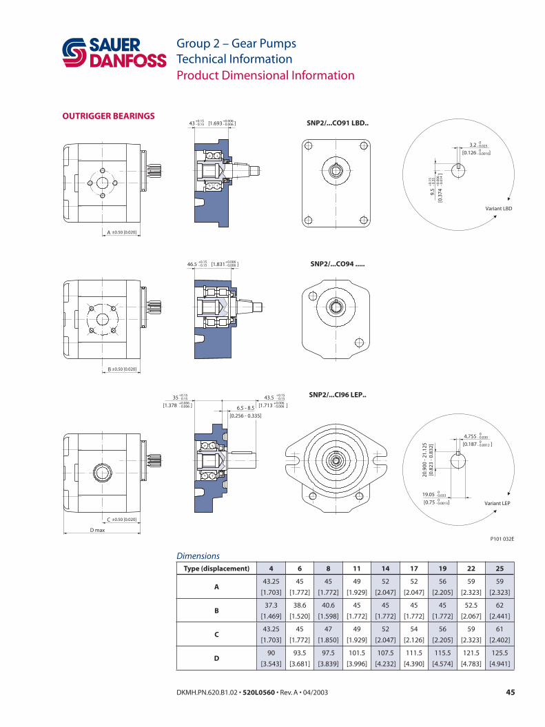
44 DKMH.PN.620.B1.02 • 520L0560 • Rev. A • 04/2003 45DKMH.PN.620.B1.02 • 520L0560 • Rev. A • 04/2003
Group 2 – Gear PumpsTechnical Information
Group 2 – Gear PumpsTechnical InformationProduct Dimensional Information
OUTRIGGER BEARINGS
SNP2/...CI96 LEP..
SNP2/...CO94 .....
SNP2/...CO91 LBD..
6.5 - 8.5
[0.256 - 0.335]
43 ]- 0.15+0.006- 0.006
+0.15
46.5 [1.831 ]- 0.15+0.006- 0.006
+0.15
35
[1.378 ]- 0.15+0.006- 0.006
+0.15 43.5
[1.713 ]- 0.15
+0.006- 0.006
+0.15
20.9
00 -
21.1
25[0
.823
- 0.
832]
4.755
[0.187 ]- 0.030
0- 0.0012
0
19.05
[0.75 ]- 0.033
- 0.0013
0
Variant LEP
3.2
[0.126 ]- 0.025
0- 0.0010
0
9.5
[0.3
74]
- 0.3
5+
0.00
6- 0
.014
+0.
15
Variant LBD
A ±0.50 [0.020]
B ±0.50 [0.020]
C ±0.50 [0.020]
D max
P101 032E
[1.693
0
DimensionsType (displacement) 4 6 8 11 14 17 19 22 25
A43.25
[1.703]
45
[1.772]
45
[1.772]
49
[1.929]
52
[2.047]
52
[2.047]
56
[2.205]
59
[2.323]
59
[2.323]
B37.3
[1.469]
38.6
[1.520]
40.6
[1.598]
45
[1.772]
45
[1.772]
45
[1.772]
45
[1.772]
52.5
[2.067]
62
[2.441]
C43.25
[1.703]
45
[1.772]
47
[1.850]
49
[1.929]
52
[2.047]
54
[2.126]
56
[2.205]
59
[2.323]
61
[2.402]
D90
[3.543]
93.5
[3.681]
97.5
[3.839]
101.5
[3.996]
107.5
[4.232]
111.5
[4.390]
115.5
[4.574]
121.5
[4.783]
125.5
[4.941]
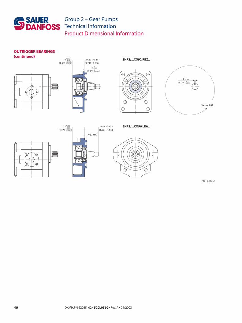
46 DKMH.PN.620.B1.02 • 520L0560 • Rev. A • 04/2003 47DKMH.PN.620.B1.02 • 520L0560 • Rev. A • 04/2003
Group 2 – Gear PumpsTechnical Information
Group 2 – Gear PumpsTechnical Information
Product Dimensional Information
OUTRIGGER BEARINGS (continued)
SNP2/...CO96 LEA..
6 [0.236]
SNP2/...CO92 RBZ..
Variant RBZ
- 0.030 04
- 0.0012 0[0.157 ]
44.22 - 45.88
[1.741 - 1.806]
35
[1.378 ]- 0.05+0.002- 0.002
+0.05
34
[1.339 ]- 0.10+0.004- 0.004
+0.10
- 0.20 08
- 0.0012 0[0.157 ]
40.48 - 39.32
[1.594 - 1.548]
P101 032E_2

46 DKMH.PN.620.B1.02 • 520L0560 • Rev. A • 04/2003 47DKMH.PN.620.B1.02 • 520L0560 • Rev. A • 04/2003
Group 2 – Gear PumpsTechnical Information
Group 2 – Gear PumpsTechnical InformationProduct Dimensional Information
AUXILIARY MOUNTING PAD
o-r
ing
pro
vid
ed82
.22x
2.62
[3.2
37x.
103]
X K
X
YM10-6H
Z
XC/c
=
A
A
=
122
[4.8
03] m
ax
115.
5 [4
.547
] max
19.5
[.76
8] m
ax
106.38 [4.188]
106.38 [4.188]
132 [5.197] max
132 [5.197] max
(R12
.7 [0
.500
] max
)
96 [3.780] max
96 [3.780] max
Ø0.50 [0.020]
= =
90.5 [3.563] max
19.5
[0.7
68] m
ax
R12.7 [0.500] m
ax(min full thd 16.7mm [0.657] deep)
Ø 0
.35
[0.0
014]
Ø 0
.10/
25.4
[0.0
04/1
]
SAE
J498
-9T-
16/3
2DP-
flat
roo
t si
de
fitci
rcu
lar t
hic
knes
s 0.
127
mm
[0.0
05] l
ess
than
sta
nd
ard
cla
ss 1
fit
Straight thread o-ring boss
A 17x14 DIN 5482
Coupling, o-ring, and screws supplied with pump
Z 0.10
[0.0
04]
Section.:A-A
Ø 0
.75
[0.0
30]
11.6
-11
[.457
-0.4
33]
0-3˚
arrow indicates direction of rotation and outlet port
SAE J498-9T-16/32DP-flat root side fit
Ø 0
.35
[0.0
14]
Splin
e: B
17 x
14
DIN
548
2p
rofil
e o
ffse
t +
0.60
0 [0
.025
]
K
X
Ø 0
.40
[0.0
16]
Y
Y
B ±0.50 [0.020]
A±0.50 [0.020]
(31.7 [1.248])
11.5-12.5 [0.453-0.492]
40.5 ±0.25 ±0.010[1.594 ]
7±0.20 ±0.008[0.276 ]
34.5±1.2 ±0.047[1.358 ]
51.5±0.90 ±0.035[2.028 ]
15.7
±0.
50±
0.03
5[0
.618
]
23.8 ±0.25 ±0.010[0.937 ]7.9 ±0.75 ±0.030[0.311 ]
20 ±0.75 ±0.030[0.787 ]
Ø15
.456
+0
+0
-0.0
05-0
.127
[0.6
09]
3 +0.006+0.1500 [0.118 ] 6.35 00
-0.020-0.50 [0.250 ]
Ø16
.50
0-0
.004
-0.1
10[0
.650
]
Ø82
.55
+0.
003
+0.
077
-0.0
01-0
.023
[3.2
50]
Ø82
.55
+0.
003
+0.
077
-0.0
01-0
.023
[3.2
50]
Ø87
+0.
002
+0.
05-0
.006
-0.1
5[3
.425
]
P101 033E
scre
ws
pro
vid
edM
10x3
0 U
NI5
931
8G b
rre
com
men
ded
to
rqu
e:40
-50N
m [3
0-37
lb•f
t]
was
her
s p
rovi
ded
10 U
NI 1
750
R40
br
90±
0.25
±0.
010
[3.5
43]
SNP2/...SC36 pump shown with auxiliary mounting pad kit installed.
Dimensions Type (displacement) 4 6 8 11 14 17 19 22 25
A43.25
[1.703]
45
[1.772]
47
[1.850]
49
[1.929]
52
[2.047]
54
[2.126]
56
[2.205]
59
[2.323]
61
[2.402]
B128.5
[5.059]
132
[5.197]
136
[5.354]
140
[5.512]
146
[5.748]
150
[5.906]
154
[6.063]
160
[6.299]
164
[6.457]
Inlet C1.063 (1 1/16) 12UN - 2B
18 mm [0.709] deep
Outlet c0.875 (7/8) - 14UNF - 2B
16.7 mm [0.658] deep

Sauer-Danfoss Mobile Power and Control Systems– Market Leaders Worldwide
Sauer-Danfoss is a comprehensive supplier providing complete systems to the global mobile market.
Sauer-Danfoss serves markets such as agriculture, construction, road building, material handling, municipal, forestry, turf care, and many others.
We offer our customers optimum solutions for their needs and develop new products and systems in close cooperation and partnership with them.
Sauer-Danfoss specializes in integrating a full range of system components to provide vehicle designers with the most advanced total system design.
Sauer-Danfoss provides comprehensive worldwide service for its products through an extensive network of Authorized Service Centers strategically located in all parts of the world.
Sauer-Danfoss (US) Company2800 East 13th StreetAmes, IA 50010, USAPhone: +1 515 239-6000, Fax: +1 515 239 6618
Sauer-Danfoss (Neumünster) GmbH & Co. OHGPostfach 2460, D-24531 NeumünsterKrokamp 35, D-24539 Neumünster, GermanyPhone: +49 4321 871-0, Fax: +49 4321 871 122
Sauer-Danfoss (Nordborg) A/SDK-6430 Nordborg, DenmarkPhone: +45 7488 4444, Fax: +45 7488 4400
www.sauer-danfoss.com
OUR PRODUCTS
Hydrostatic transmissions
Hydraulic power steering
Electric power steering
Electrohydraulic power steering
Closed and open circuit axial piston pumps and motors
Gear pumps and motors
Bent axis motors
Orbital motors
Transit mixer drives
Planetary compact gears
Proportional valves
Directional spool valves
Cartridge valves
Hydraulic integrated circuits
Hydrostatic transaxles
Integrated systems
Fan drive systems
Electrohydraulics
Microcontrollers and software
Electric motors and inverters
Joysticks and control handles
Displays
Sensors
DKMH.PN.620.B1.02 • 520L0560 • Rev. A • 04/2003


