
Rev. A – November 2010 - 110124-3000A
DIGITAL TECHNOLOGIES FOR A BETTER WORLD
www.eurotech.com
HARDWARE REFERENCE MANUAL
Helios™ Platform Programmable Edge Controller
Disclaimer
The information in this document is subject to change without notice and should not be construed as a commitment by any Eurotech company. While reasonable precautions have been taken, Eurotech assumes no responsibility for any error that may appear in this document.
Trademarks
Helios™ and Everyware™ are trademarks of Eurotech Inc. All other product or service names are the property of their respective owners.
Revision History
Issue no. PWB Date Comments 1 Jul-09 Preliminary release
2 Oct-09 Second preliminary release
A Nov-10 Updates for Rev B carrier boards
© 2009 Eurotech Inc. For contact details, see page 24.
Contents
110124-3000A 3
Contents Introduction ............................................................................................................................ 4
Block Diagram ........................................................................................................... 4 Features .................................................................................................................... 5 Further Reading ......................................................................................................... 6 Handling Your System Safely ..................................................................................... 6 Conventions ............................................................................................................... 6
Software Support ................................................................................................................... 8 Operating System ...................................................................................................... 8 BIOS .......................................................................................................................... 8 Boot Options .............................................................................................................. 8 Everyware™ Software Framework .............................................................................. 8
Hardware Reference .............................................................................................................. 9 Rear Panel ................................................................................................................. 9 USB Bay ................................................................................................................... 11 Indicators ................................................................................................................. 12 Enclosure ................................................................................................................. 13
Configurations ..................................................................................................................... 14 Processor ................................................................................................................ 14 Memory .................................................................................................................... 14
CompactFlash® Card or Secure Digital Card ................................................ 14 On-Board Flash ............................................................................................ 14 SATA Drive ................................................................................................... 14 USB Disk Drive ............................................................................................ 15
Communications ...................................................................................................... 15 Universal Serial Bus ..................................................................................... 15 Serial Port .................................................................................................... 15 Ethernet ....................................................................................................... 15 GPS ............................................................................................................. 15
Multimedia Cards ..................................................................................................... 16 Power Supply ........................................................................................................... 16
Peripherals .......................................................................................................................... 17 USB Device Support ................................................................................................ 17
System Specification ............................................................................................................ 18 Processor ................................................................................................................ 18 Power ...................................................................................................................... 18 Electrical .................................................................................................................. 19 EMI/EMC ................................................................................................................. 20 Environmental .......................................................................................................... 21
Appendix A – Reference Information .................................................................................... 22 Appendix B – System Revision ............................................................................................ 23 Eurotech Worldwide Presence ............................................................................................. 24

Helios Platform - Hardware Reference Manual
110124-3000A 4
Introduction
Helios™ is a programmable edge controller that provides a flexible application-ready hardware platform with enhanced wireless capabilities. It is based on the Catalyst XL which integrates with a carrier board and supporting peripheral devices. All electronics are housed in an enclosure. Three USB host ports for wireless devices and additional storage are accessible in the USB Bay located under the removable cover.
With the Helios platform, you can quickly and easily create an edge controller device, loaded with your application software that precisely meets your requirements. Several options are available allowing you to choose the hardware based on your specifications. Using pre-certified wireless modules in the USB Bay, the Helios platform can be easily customized for any network. Software support includes Eurotech’s Everyware™ Software Framework offering an easy-to-use, Java-based development environment that minimizes time to market and allows for easy portability for future expansion.
Block Diagram The following diagram illustrates the system organization of the Helios platform. Notice that the data connector on the Catalyst XL has been divided into two sections for this illustration. Dotted lines indicate configuration options. For information about these options, see Configurations, page 14.
Catalyst XL
1 x SD/MMC
Intel® Atom™ Processor
(Z5xx)
IDE/PATA
SDVO
1 x PCIe
HD Audio
Pwr Supply
FSB
LPC Bus
TPM
VBAT (RTC)
Gigabit Ethernet Port
1 x USB2.0
CF Cardor
SD Card (optional)
V Reg
DDR-2 DRAM
BAT
Embedded Ctrl
BIOS
I2C BusSys Mgmt I/O
GPIOs
1 x PCIeGigE Controller
SMBus
LM75Temp Monitor
I2C GPIOMomentary Switch
8 x LED
On-board PATA flash
LVDS Video
1 x USB2.0
Regulated Power Input(optional Vehicle Pwr)
Sys Ctrls
Pwr LED
3 x USB2.0
2 x USB2.0
3 x USB2.0 Host Ports (USB Bay )
2 x USB2.0 Host Ports
Sys Ctrls
Pwr LED
SMBus GPIO
Intel®SCH US15W
SMBus
Helios™ Platform
Audio Codec
SDVO to VGA
Stereo Line InStereo Line OutMicrophone In
VGA Display Out
Expansion Board Support(VGA expansion board shown)
SATADrive
SATA Controller
EIA 232/485Serial Port
USB to Serial
US
B H
ub
GPS Rcvr
GPS Antenna Connector
Introduction
110124-3000A 5
Features
Processor • Intel® Atom™ Z5xx processor at 1.1 GHz (options for 1.33 GHz or 1.6 GHz)
• Intel® System Controller Hub US15W
Integrated System Functions • Embedded Controller
• Trusted Platform Management (option)
Memory • 1 GB DDR-2 DRAM (options for 512 MB or 2 GB)
• Integrated system BIOS
• Battery-backed real-time clock
• On-board PATA flash (option)
• CompactFlash® card or SD card (option)
• Internal SATA drive (option)
• External USB disk drive support
Communications • Five USB 2.0 host ports operating low, full, and high speeds
- Two general-purpose ports - Three USB Bay ports for wireless devices and storage
(option for up to three external antenna connections)
• EIA-232/EIA-485 serial port (software-selectable)
• Gigabit Ethernet port
• GPS receiver with external antenna connection (option)
User Interface and Display • Multimedia card support for various display and audio options
(For details about expansion boards, see Multimedia Cards, page 16.)
• Power indicator
• Seven software-controlled LED status indicators
• Software-readable push-button
Power Supply • 12 V DC power input (up to 36 V vehicle power input option)
Mechanical • ABS plastic and aluminum enclosure
Helios Platform - Hardware Reference Manual
110124-3000A 6
Further Reading This document describes the Helios platform and is intended for system integrators. A system-level overview is provided in the following sections. Check the Eurotech support site (http://support.eurotech-inc.com/) for errata reports and for the latest releases of these documents.
Handling Your System Safely
Anti-Static Handling The Helios platform is designed to meet the Electrostatic Discharge (ESD) criteria contained in IEC 61000-4-2 (EMC – Part 4-2: Testing and Measurement Techniques – Electrostatic Discharge Immunity Test). The electronics included in the enclosure contain CMOS devices that could be damaged by electrostatic discharge (ESD). Observe industry-standard electronic handling procedures when handling these electronics. Where possible, work on a grounded anti-static mat. At a minimum, touch an electrically grounded object before handling any electronics.
Packaging Please ensure that, should a system need to be returned to Eurotech, it is adequately packed, preferably in the original packing material.
Electromagnetic Compatibility The Helios platform is defined as an unintentional radiator of electromagnetic energy. For additional information about the EMI/EMC specification, see EMI/EMC, page 20.
Conventions The following table lists the symbols used in this document.
Symbol Explanation
Note – information that requires your attention
Warning – proceeding with a course of action may damage your equipment or result in loss of data
The following table describes the conventions for signal names used in this document.
Convention Explanation GND digital ground plane
+ positive signal in differential pair
- negative signal in differential pair
Introduction
110124-3000A 7
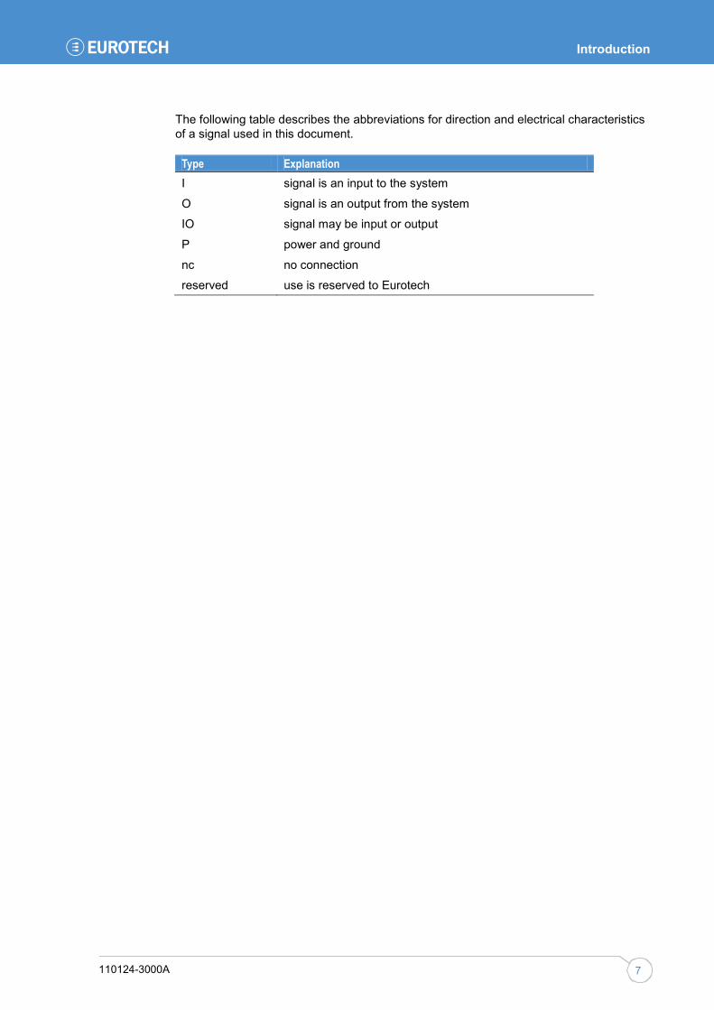
The following table describes the abbreviations for direction and electrical characteristics of a signal used in this document.
Type Explanation I signal is an input to the system
O signal is an output from the system
IO signal may be input or output
P power and ground
nc no connection
reserved use is reserved to Eurotech

Helios Platform - Hardware Reference Manual
110124-3000A 8
Software Support
Eurotech provides an application-ready platform including BIOS, operating system, and development environment. This section gives a brief description of the software support available for the Helios platform. For additional details, contact your local Eurotech technical support.
Operating System The Helios platform is available with the following operating systems:
• Wind River Linux 3.0
• Windows® Embedded Standard
• Windows® CE 6.0
BIOS The Helios platform incorporates a custom system BIOS developed by Eurotech.
Boot Options The Helios platform has the capability to boot and install the operating system from five sources. The following are the boot options:
• CF card
• USB disk drive
• SD card (future option)
• SATA drive
• On-board PATA flash
Everyware™ Software Framework Everyware Software Framework (ESF) is an inclusive software framework that puts a middleware layer between the operating system and the OEM application. It provides industry-standard interfaces that shorten development time, simplify coding, and allow software to be ported from one Eurotech hardware platform to another. ESF is available on the Helios platform.
Information about ESF is available at http://esf.eurotech.com.

Hardware Reference
110124-3000A 9
Hardware Reference
This section gives an overview of the hardware features of the Helios platform. The overview includes location and function of connectors, indicators, and switches and details about the enclosure.
Rear Panel The following diagram illustrates the location of connectors and switches on the rear panel. Notice that the system shown uses the VGA Expansion Board and includes additional connectors not found on the standard system. For other multimedia card options, see Multimedia Cards, page 16.
Standard system The following table describes the connectors on the rear panel of a standard system.
Connector Enclosure Connector Description Power 1 x 2 header, 3.5 mm Main power input
USB 1-2 USB Type A receptacle USB 2.0 host ports
Serial DB-9 plug EIA-232 (default) or EIA-485
Ethernet RJ-45 socket Gigabit Ethernet network
GPS SMA socket GPS external antenna connection Antenna 1-3 Device dependent USB device external antenna connections
(optional)
USB
Serial
Ethernet GPS
Power
Display Output
Line Out
Line In
Microphone
Antenna Connections
Switch
Helios Platform - Hardware Reference Manual
110124-3000A 10
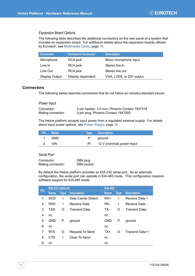
Expansion Board Options The following table describes the additional connectors on the rear panel of a system that includes an expansion board. For additional details about the expansion boards offered by Eurotech, see Multimedia Cards, page 16.
Connector Enclosure Connector Description Microphone RCA jack Mono microphone input
Line In RCA jack Stereo line in
Line Out RCA jack Stereo line out
Display Output Display dependent VGA, LVDS, or DVI output
Connectors The following tables describe connectors that do not follow an industry-standard pinout.
Power Input Connector: 2-pin header, 3.5 mm, Phoenix Contact 1937318 Mating connector: 2-pin plug, Phoenix Contact 1847055
The Helios platform accepts input power from a regulated external supply. For details about input power options, see Power Supply, page 16.
Pin Name Type Description 1 GND P ground
2 VIN PI 12 V (nominal) power input
Serial Port Connector: DB9 plug Mating connector: DB9 socket
By default the Helios platform provides an EIA-232 serial port. As an alternate configuration, the serial port can operate in EIA-485 mode. This configuration requires software support for EIA-485 mode.
Pin EIA-232 (default) EIA-485 Name Type Description Name Type Description
1 DCD I Data Carrier Detect RX+ I Receive Data +
2 RXD I Receive Data RX- I Receive Data -
3 TXD O Transmit Data TX- O Transmit Data -
4 nc nc
5 GND P ground GND P ground
6 nc nc
7 RTS O Request To Send TX+ O Transmit Data +
8 CTS I Clear To Send nc
9 nc nc
Hardware Reference
110124-3000A 11
Boot Mode Button The Helios platform includes a momentary push-button switch accessible through a small hole on the rear panel near the GPS connector. This switch generates an interrupt to the processor and is software-definable.
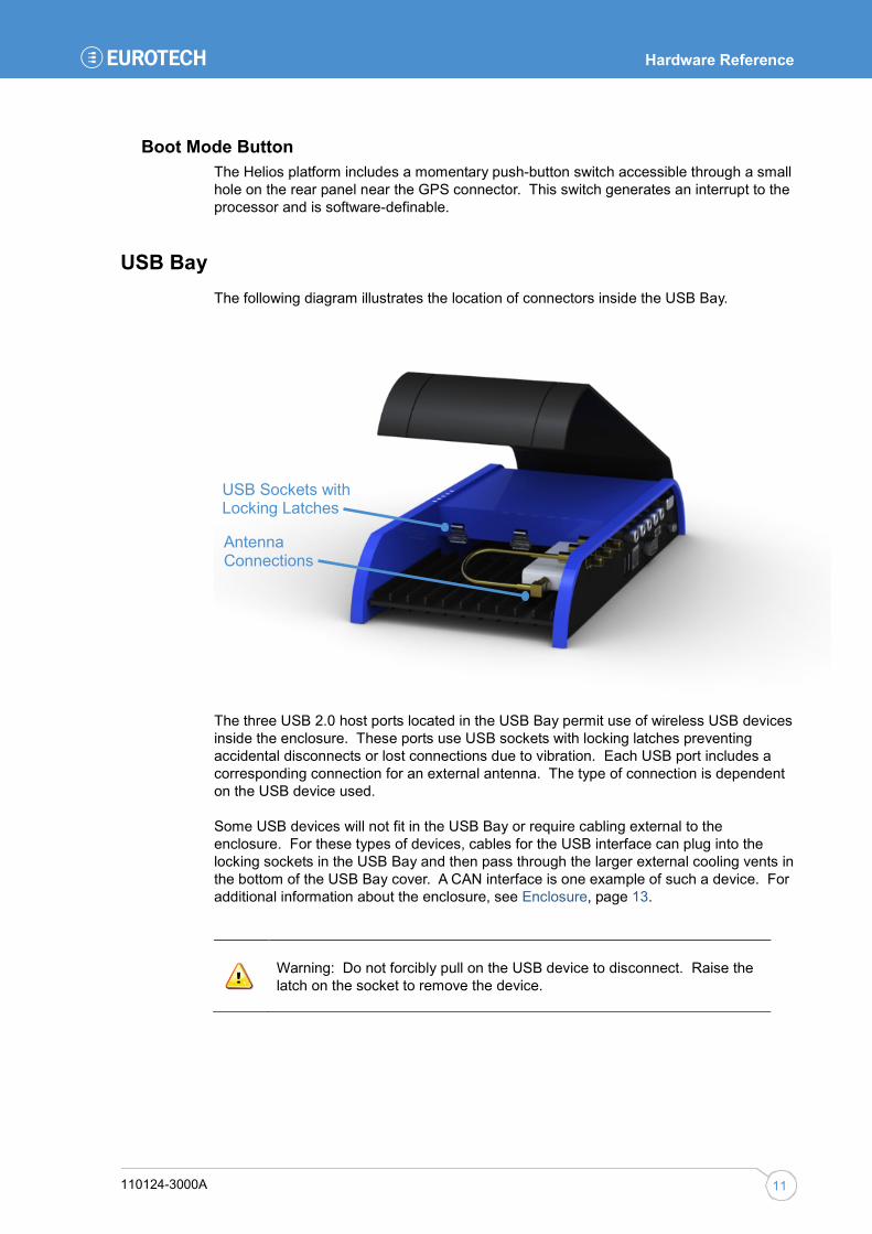
USB Bay The following diagram illustrates the location of connectors inside the USB Bay.
The three USB 2.0 host ports located in the USB Bay permit use of wireless USB devices inside the enclosure. These ports use USB sockets with locking latches preventing accidental disconnects or lost connections due to vibration. Each USB port includes a corresponding connection for an external antenna. The type of connection is dependent on the USB device used.
Some USB devices will not fit in the USB Bay or require cabling external to the enclosure. For these types of devices, cables for the USB interface can plug into the locking sockets in the USB Bay and then pass through the larger external cooling vents in the bottom of the USB Bay cover. A CAN interface is one example of such a device. For additional information about the enclosure, see Enclosure, page 13.
Warning: Do not forcibly pull on the USB device to disconnect. Raise the latch on the socket to remove the device.
USB Sockets with Locking Latches
Antenna Connections
Helios Platform - Hardware Reference Manual
110124-3000A 12
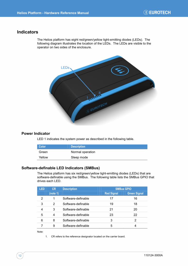
Indicators The Helios platform has eight red/green/yellow light-emitting diodes (LEDs). The following diagram illustrates the location of the LEDs. The LEDs are visible to the operator on two sides of the enclosure.
Power Indicator LED 1 indicates the system power as described in the following table.
Color Description Green Normal operation
Yellow Sleep mode
Software-definable LED Indicators (SMBus) The Helios platform has six red/green/yellow light-emitting diodes (LEDs) that are software-definable using the SMBus. The following table lists the SMBus GPIO that drives each LED.
LED CR Description SMBus GPIO (note 1) Red Signal Green Signal 2 1 Software-definable 17 16
3 2 Software-definable 19 18
4 3 Software-definable 21 20
5 4 Software-definable 23 22
6 8 Software-definable 3 2
7 9 Software-definable 5 4
Note:
1. CR refers to the reference designator located on the carrier board.
LEDs
1 8
Hardware Reference
110124-3000A 13
Software-definable LED Indicators (I2C Bus) LED 8 is software-definable using the I2C bus. The following table lists the I2C Bus GPIO that drives this LED.
LED CR Description I2C Bus GPIO (note 2) Red Signal Green Signal 8 6 Software-definable 1 0
Note:
2. CR refers to the reference designator located on the carrier board.
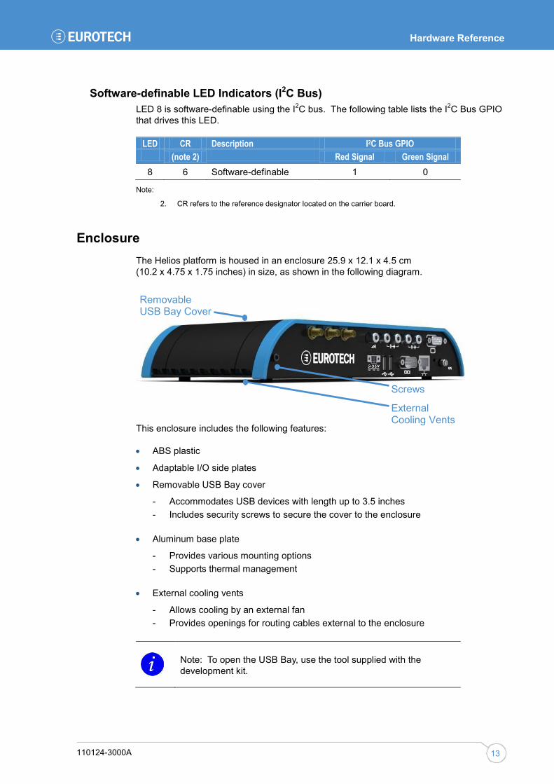
Enclosure The Helios platform is housed in an enclosure 25.9 x 12.1 x 4.5 cm (10.2 x 4.75 x 1.75 inches) in size, as shown in the following diagram.
This enclosure includes the following features:
• ABS plastic
• Adaptable I/O side plates
• Removable USB Bay cover
- Accommodates USB devices with length up to 3.5 inches - Includes security screws to secure the cover to the enclosure
• Aluminum base plate
- Provides various mounting options - Supports thermal management
• External cooling vents
- Allows cooling by an external fan - Provides openings for routing cables external to the enclosure
Note: To open the USB Bay, use the tool supplied with the development kit.
Screws
External Cooling Vents
Removable USB Bay Cover

Helios Platform - Hardware Reference Manual
110124-3000A 14
Configurations
The Helios platform’s flexible design enables several options supporting many possible combinations to meet your system requirements. These options are factory-installed, and the system is configured for operation at the factory with the specific combination of options. This section describes the options available for the Helios platform.
Processor The Helios platform bases its architecture on the high-performance, low-power Catalyst XL. This module uses an integrated two-chip solution comprised of the Intel Atom Z5xx processor and Intel SCH US15W.
The Catalyst XL is available in various versions based on the following features:
• Processor speed
• On-module DRAM
• Operating temperature
The standard system includes a 1.1 GHz, 1 GB Catalyst XL for the commercial temperature range. For the various performance variants, see Processor, page 18.
Memory Five types of memory provide mass storage options for the Helios platform. In addition, the system can boot from any of these memory options. For information about boot options, see Boot Options, page 8. The following sections describe the memory options.
CompactFlash® Card or Secure Digital Card The standard system includes a CompactFlash (CF) card. As a volume production option, a Secure Digital (SD) card can replace the CF card. Each type of card is located internal to the enclosure and is not accessible when the system is completely assembled.
Note: The CF card slot and the SD card slot are mutually exclusive. Only one socket can be installed. This option is set at time of production. The CF card slot is the default.
On-Board Flash On-board Parallel ATA (PATA) flash is available as an option, populated in increments of 1 GB.
SATA Drive As an option, the Helios platform can include a single, 2.5-inch form factor SATA drive internal to the enclosure. For SATA drive specifications, see SATA Drive, page 19.
Configurations
110124-3000A 15
USB Disk Drive A USB disk drive can connect to any of the five USB host ports on the Helios platform.
Communications A key capability of the Helios platform is its network and wireless connectivity. The system offers five USB host ports, an EIA-232/485 serial port, a Gigabit Ethernet port, and GPS. The following sections describe these interfaces.
Universal Serial Bus Five Universal Serial Bus (USB) ports included on the Helios platform support connectivity with a wide range of available USB devices. All ports support the USB 2.0 specification operating at high (480 Mbps), full (12 Mbps), or low (1.5 Mbps) speeds. Two ports are general-purpose USB host ports, while the remaining three ports are designed to support higher-current, plug-in USB modules.
For power requirements, see Universal Serial Bus, page 19. For additional information about the high-current USB ports, see USB Device Support, page 17.
Serial Port The Helios platform provides a serial port accessible on the rear panel. By default, this port is an EIA-232, 6-wire interface. Under software-control, the port can be configured as an EIA-485 interface.
Ethernet For network connectivity, the Helios platform includes a Gigabit Ethernet port.
GPS The standard system includes a u-blox GPS module with an external antenna connection on the rear panel. This module is a population option.

Helios Platform - Hardware Reference Manual
110124-3000A 16
Multimedia Cards To provide custom display and audio solutions, the Helios platform includes an internal card slot for add-in multimedia cards. This hardware flexibility enables the Helios platform to support a wide variety of display types and audio requirements.
Eurotech offers various expansion boards for use with the Helios platform as described in the following table. For additional details, contact your local Eurotech sales representative.
Expansion Board Display Audio VGA Analog RBG output
S-Video output (option) CBVS output (option)
Stereo line input Stereo line output Microphone input
LVDS LVDS display output Backlight control Touch panel controller
Stereo line input Stereo line output Microphone input
DVI/HDMI DVI output HDMI (option)
Stereo line input Stereo line output
For electrical specifications, see Audio Interface, page 20.
Power Supply The standard system requires a regulated DC power input. As an option, the Helios platform can be powered from vehicle rated power. For power specifications, see Power, page 18.

Peripherals
110124-3000A 17
Peripherals
Support for a wide variety of plug-in USB devices enables the Helios platform to be easily customized for any application. This section describes the types of peripherals available for use with the Helios platform.
USB Device Support The three USB ports located in the USB Bay expand the capability and connectivity of the Helios platform, in addition to providing the option to boot from a USB device. These ports enable customization for your specific application with no hardware modifications to the system.
The Helios platform supports the following types of USB devices:
• Cellular modem
• ZigBee
• Wi-Fi
• Bluetooth
• Telematics / CAN
• Mass storage
• HID (Human Interface Device)
For additional information about the USB Bay, see USB Bay, page 11.
Eurotech has pretested and approved several USB devices for use with the Helios platform. For the latest list of devices, contact your local Eurotech sales representative.

Helios Platform - Hardware Reference Manual
110124-3000A 18
System Specification
Processor The Helios platform is based on the Catalyst XL and is compatible with all versions of the module allowing several performance variants. The following table specifies the processor performance.
Parameter (note 3) Min Typ. Max Units Processor operating frequency (commercial temperature) 1.1 1.6 GHz
Processor operating frequency (industrial temperature) 1.1 1.33 GHz
Front side bus clock 400 533 MHz
Front side bus width 64 bit
On-board DDR-2 DRAM 512 2000 MB
Notes:
3. The standard Helios platform includes a 1.1 GHz, 1 GB Catalyst XL, commercial temperature.
Power
Power Supply The following table specifies the power requirements for the Helios platform. For additional information about the input voltage options, see Power Supply, page 16.
Symbol Parameter Min Typ. Max Units Input Voltage
VIN Input voltage, regulated power 10.8 12 13.2 V
Input voltage, vehicle power (note 4) 9 36 V
VINTRANS Input transient voltage, regulated power 36 V
Input transient voltage, vehicle power 100 V
tUV/OV Overvoltage or undervoltage timeout (note 5)
87 ms
Notes:
4. The Helios platform is designed to be unpowered when vehicle ignition is off.
5. The input protection circuitry immediately cuts off the main input power when an overvoltage or undervoltage condition occurs. These conditions are the minimum and maximum input voltage specified for vehicle power. Power is restored tUV/OV after VIN becomes valid.

System Specification
110124-3000A 19
Power Consumption The following table lists power consumption for various configurations of the Helios platform.
Symbol Parameter Min Typ. Max Units Fully loaded, without USB (note 7)
P Power 12 W
IINRUSH Inrush current 17 A
Fully loaded, with USB devices (note 8)
P Power 15 W
IINRUSH Inrush current 18 A
Notes:
6. Power consumption was measured on a Helios platform with a VGA Expansion Board and the following conditions: 12 V input voltage, video and audio clips playing from a SATA drive, Ethernet port pinged, serial port transferring a file in 1K XMODEM at 115200 baud, and GPS unit responding consistently.
7. Power consumption was measured on a Helios platform with a VGA Expansion Board and the following conditions: 12 V input voltage, Belkin Wi-Fi device enabled and playing a video, Verizon cellular modem enabled, video and audio clips playing from a SATA drive, Ethernet port pinged, serial port transferring a file in 1K XMODEM at 115200 baud, and GPS unit responding consistently.
Electrical This section provides electrical specifications for the Helios platform.
Universal Serial Bus The Helios platform provides five USB host ports. Each port supplies 5 V power through a power switch with over-current detection. For a description of the USB host ports, see Universal Serial Bus, page 15.
Symbol Parameter Min Typ. Max Units General-purpose USB Ports
IUSB USB current 500 mA
USB Bay Ports
IUSB USB current 1 A
SATA Drive The following table lists the specification for the optional SATA drive. For additional information, see SATA Drive, page 14.
Parameter Min Typ. Max Units Transfer rate (SATA2) 300 MBps
Power consumption (seek) 3 W
Power consumption 1 W

Helios Platform - Hardware Reference Manual
110124-3000A 20
Real-Time Clock The Helios platform provides a RTC function that retains the system date and time. To supply backup power when the power input is disconnected, the system includes a long-life, lithium coin battery. The following table specifies the RTC function.
Parameter Typ. Units Accuracy per month @ 25°C +/-55 sec
Battery 3 V
Operating temperature -30 to +80 °C
Warning: The RTC battery is located inside the enclosure and is not user serviceable. Incorrect removable of the module or battery could damage the Catalyst XL.
Audio Interface The following table lists the specification for the audio interface provided by the optional expansion boards. For additional information, see Multimedia Cards, page 16.
Symbol Parameter Min Typ. Max Units DVDD Codec digital supply voltage 3.3 V
AVDD Codec analog supply voltage 3.3 V
fS Sample rate 192 kHz
--- A/D sample resolution 24 bit
Line In, Microphone
VIN Full scale input voltage 1.00 1.03 Vrms
GainIN Microphone boost 0 30 dB
RIN Input impedance 50 kΩ
CIN Input capacitance 15 pF
Line Out
VOUT Full scale output voltage, 10kΩ load 0.707 0.758 Vrms
PUT Headphone output, 32Ω load 31 42 mW
(peak)
EMI/EMC The Helios platform is designed to meet the EMI/EMC requirements listed in the following table. The external USB wireless devices are covered by separate qualifications.
Requirement Characteristic Condition/Comments EN 55022/CISPR22 Emissions Sub-clause 8.2 - EN 55022/CISPR 22 for class B
device - Radiated emissions for 30 MHz – 1 GHz EN 55022/CISPR22 Immunity Sub-clause 9.3 - EN61000-4-2 - Electrostatic
discharge. Sub-clause 9.2 - EN 61000-4-3 - Radiated immunity
FCC CFR47 Part 15/B Emissions Rules 15.101-109

System Specification
110124-3000A 21
Environmental The Helios platform is designed to meet the environmental specifications listed in the following table.
Parameter Specification Commercial operating temperature 0°C to +70°C
Industrial operating temperature (note 8) -40°C to +85°C
Vibration profile SAE J1455-2006, vehicle
Shock Mil-Std-810F, 20 g/s, 11 ms
Drop 1 m, hard surface, cosmetic damage only
Humidity 95% non-condensing
Ingress protection (IEC 60529) IP-50 (note 9)
Notes:
8. The industrial temperature range is available as a volume production option.
9. Enclosure protects electronics from dust. It does not protect against water ingress.
Helios Platform - Hardware Reference Manual
110124-3000A 22
Appendix A – Reference Information
Product Information Product notices, updated drivers, support material:
www.eurotech.com
Intel Information about the Intel Atom processor, Intel System Controller Hub US15W, Intel High Definition Audio specification:
www.intel.com
USB Universal Serial Bus specification and product information:
www.usb.org
SD Card SD Card Association and SDIO specification:
www.sdcard.org
MMC Card JEDEC MMC 4.0 specification:
www.jedec.org
CompactFlash CompactFlash Association and specification:
www.compactflash.org

Appendix B – System Revision
110124-3000A 23
Appendix B – System Revision
This manual applies to the current revision of the Helios platform as given in the following sections.
Revision History The following is an overview of the revisions to the system.
Revision 1 Prototype
Revision A Changes control and brightness of LED indictors
Revision B Adds software control for switching between EIA-232 mode and EIA-485 mode
Swaps pin 4 and pin 7 on Serial Port for EIA-485 mode
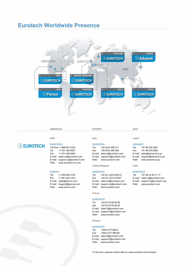
Eurotech Worldwide Presence
To find your nearest contact refer to: www.eurotech.com/contacts
www.eurotech.com
EUROPE Italy EUROTECH Tel. +39 0433.485.411 Fax +39 0433.485.499 E-mail: [email protected] E-mail: [email protected] Web: www.eurotech.com United Kingdom EUROTECH Tel. +44 (0) 1223.403410 Fax +44 (0) 1223.410457 E-mail: [email protected] E-mail: [email protected] Web: www.eurotech.com France EUROTECH Tel. +33 04.72.89.00.90 Fax +33 04.78.70.08.24 E-mail: [email protected] E-mail: [email protected] Web: www.eurotech.com Finland EUROTECH Tel. +358 9.477.888.0 Fax +358 9.477.888.99 E-mail: [email protected] E-mail: [email protected] Web: www.eurotech.com
ASIA Japan ADVANET Tel. +81 86.245.2861 Fax +81 86.245.2860 E-mail: [email protected] E-mail: [email protected] Web: www.advanet.co.jp India EUROTECH Tel. +91 80.43.35.71.17 E-mail: [email protected] E-mail: [email protected] Web: www.eurotech.com
AMERICAS USA EUROTECH Toll free +1 888.941.2224 Tel. +1 301.490.4007 Fax +1 301.490.4582 E-mail: [email protected] E-mail: [email protected] Web: www.eurotech-inc.com PARVUS Tel. +1 800.483.3152 Fax +1 801.483.1523 E-mail: [email protected] E-mail: [email protected] Web: www.parvus.com

www.eurotech.com
EUROTECH HEADQUARTERS Via Fratelli Solari 3/a 33020 Amaro (Udine) – ITALY Phone: +39 0433.485.411 Fax: +39 0433.485.499 For full contact details go to: www.eurotech.com/contacts


