file:///C|/Documents%20and%20Settings/Kenneth%20Grimm/Desktop/FOR%20BAMA/59LF-coil-construction/email.txt
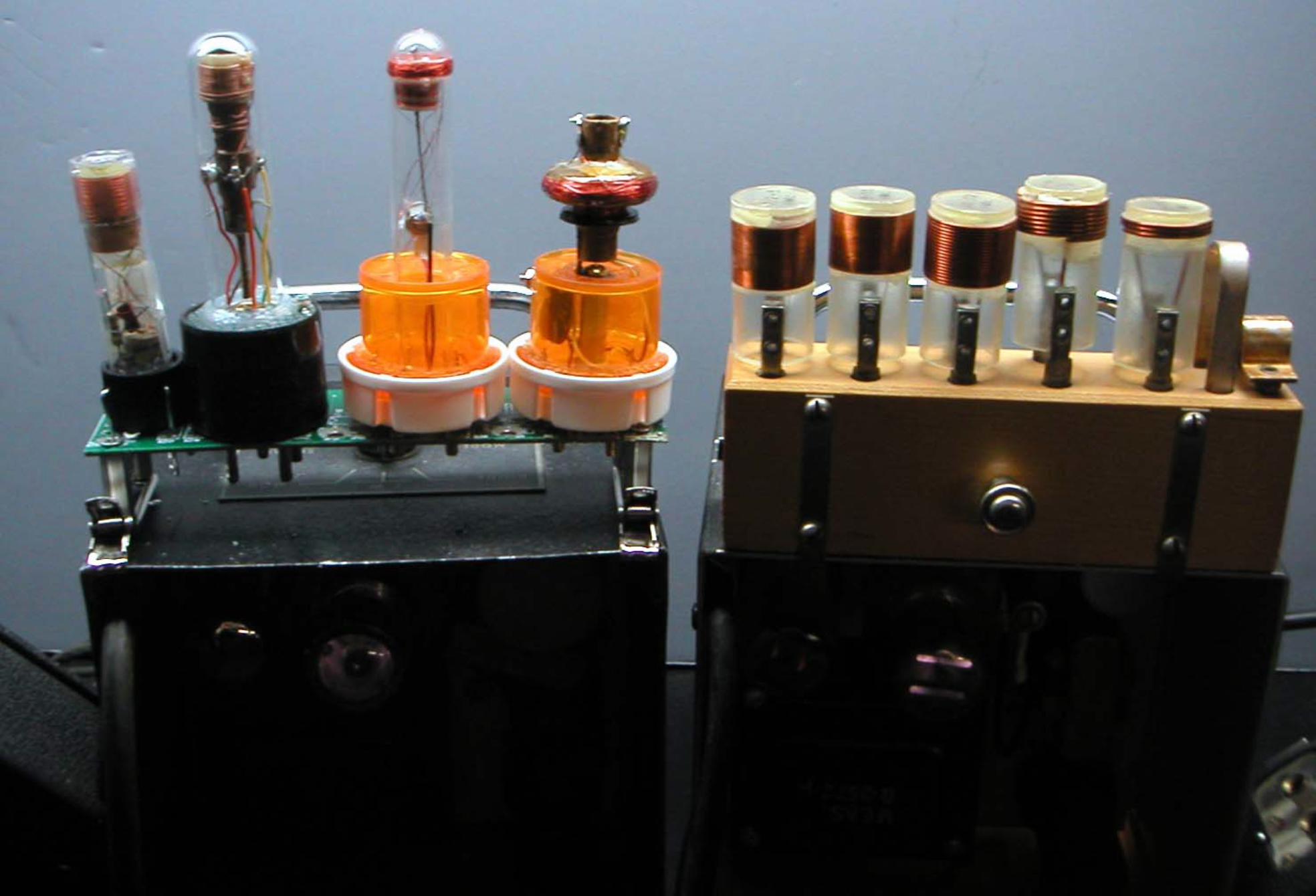
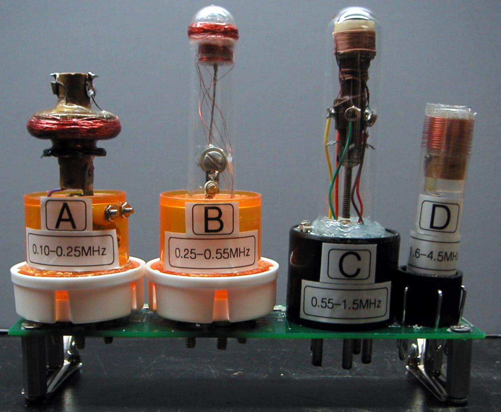
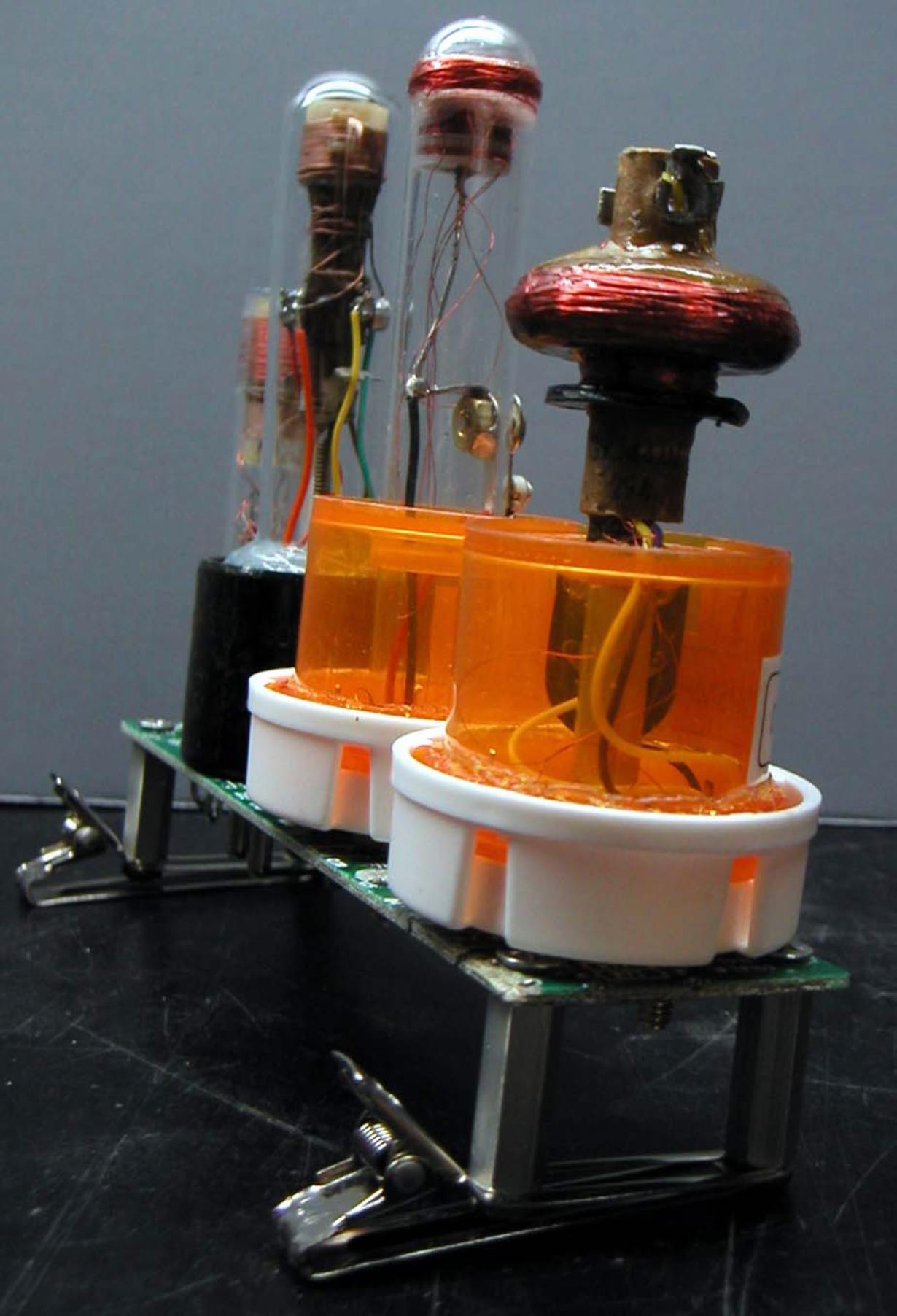
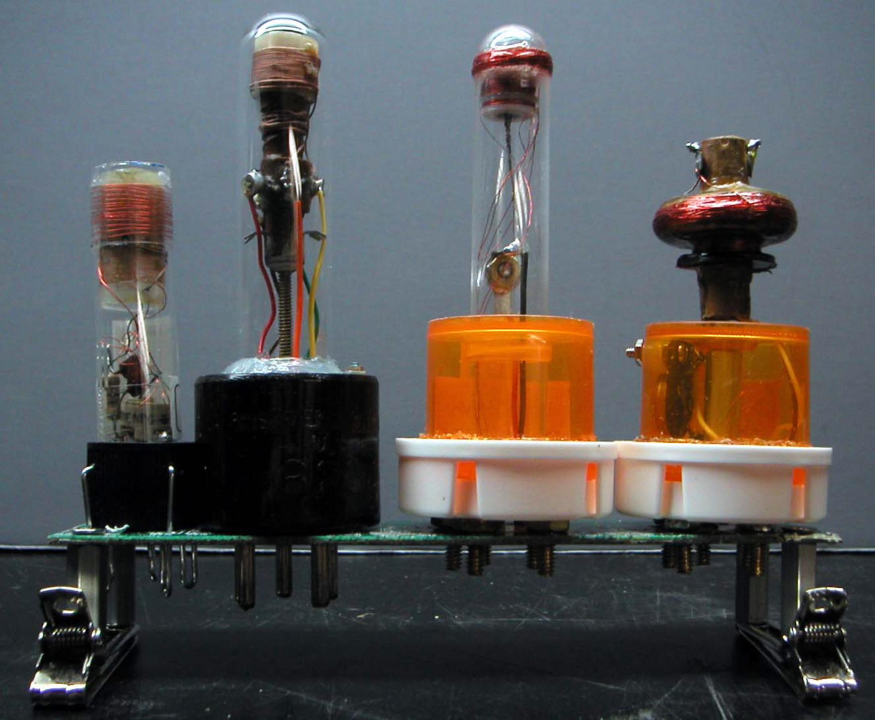
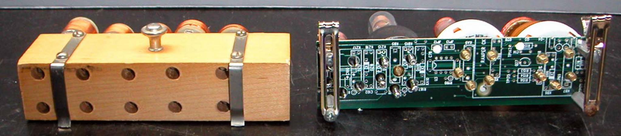
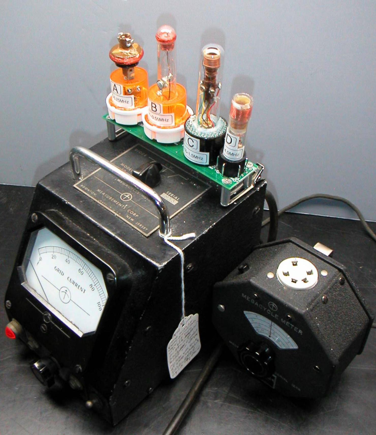
Hi Ken,I am forwarding the email from Alan Douglas with his measurements of the original 59LF coils, along with a picture he sent.I also attached the final configuration of my coils. My main coil values came out very close to Alan's measurements, but I ended up putting the coils together, with the trim caps before measuring the final values of all the coils.Regards,-Joe
------------------------------Hi Joe,
Thanks for sharing the excellent photos. If you could provide a table of the inductance values, I think that the photos plus the values might make a nice addition to the 59LF collection.
Thanks again,
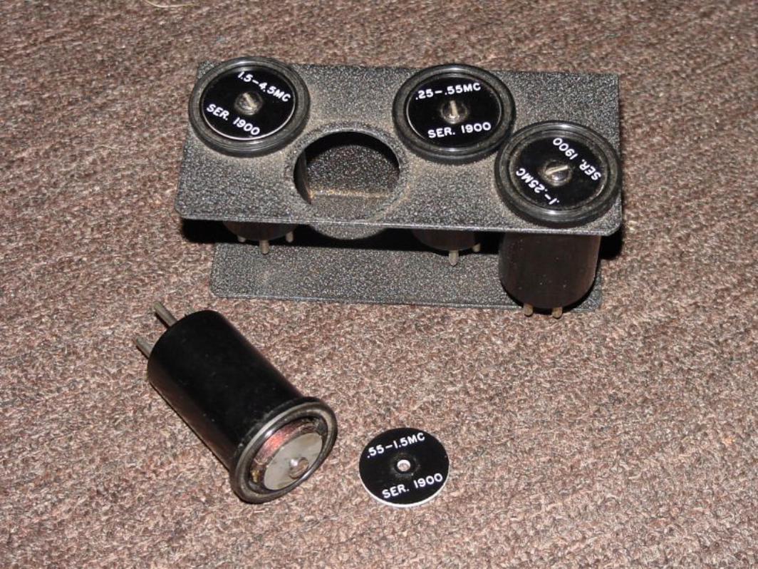
> To: Joe Sousa <JLRMSousa at Comcast.net>> From: Alan Douglas <adouglas at gis.net>> Subject: Re: 59LF Megacycle Meter> X-Rcpt-To: <JLRMSousa at Comcast.net>>> Hi,> Photo enclosed. This is as far as I can open the coil forms without> unsoldering the wires. Coils are universal-wound on ferrite slugs 7/8"> diameter, maybe an inch long. They're held on with wax and I can't count turns. Inductances (1 kHz) as follows, in microHenries:>> pins 1-2 pins 3-4 pins 3-5>> A: 59, 5000, 22.>> B: 5.5, 900, 2.2>> C: 2.8, 200, 11.6>> D: 1.9, 27, *>> * = can't read because of 1k resistor in series.>> I presume you have the schematic, but pin 3 is the cold end of the coil,> hot end to pin 4, tap to pin 5. Feedback winding is 1 and 2.>> A .1-.25MHz, B .25-.55, C .55-1.5, D 1.5-4.5.>> The basic coil forms are by Na-Ald (Alden), standard stuff in the 1930s> and 40s.>> Alan
www.PhilbrickArchive.orgA free repository of materials fromGAP/R, George A. Philbrick /Researches.Operational Amplifier Pioneer.
file:///C|/Documents%20and%20Settings/Kenneth%20Grimm/Desktop/FOR%20BAMA/59LF-coil-construction/email.txt12/19/2008 10:19:50 PM