
1
Horological Wheel Cutting -
(Jerry Kieffer’s) Modern Means &
Methods
Authored By: David M. Morrow, CC21
Twenty First Century Certified Clockmaker
American Watchmakers-Clockmakers Institute

2
Table of Contents/Index Page(s)
Introduction 4
Tooth Forms 5-8
Involute 6
Cycloidal 7-8
Cutters 9-16
Theory 9
Commercial Cutters 10-12
Involute Cutters 10
Cycloidal Cutters 11-12
Custom Single Point Cutter a/k/a Fly Cutters 13-14
More About DP & Module 14-16
Helpful tips for micro milling 17-18
Section 1: Cutting Train Wheel Teeth 19-70
Summary of Major Tasks 19
Task 1: Calculations for wheel cutting 20-25
Task 2: Material choices and specifications 26-28
for arbor, tightening washer, backer plate and end mills
Task 3: Machine the arbor 29-34
Task 4: Tightening washer: Buy it or machine it 35
Task 5: Machine backer plate 35
Task 6: Machine wheel blank 36-43
Boring bar tools: Buying, making & using 37-42
Task 7: Machine single point cutter 44-59
Wheel Cutting Worksheet/Calculating Work Point Offsets 44-45
First Cut 50-52
Second Cut 52
Third Cuts 53-55
Fourth Cuts 56-58
Round Bottom Tooth Spaces 59
Task 8: Harden single point cutter 60
Task 9: Sharpen single point cutter 61
Task 10: Milling machine/CNC rotary table setup 61-65
Task 11: Wheel cutting 66-71
Resizing Wheel Teeth 71

3
Section 2: Cutting Escape Wheels 72-86
Grinding pallet surfaces 84-86
Using a micro mill as a surface grinder 86
Section 3: Cutting Ratchet Wheels 87-101
Section 4: Replacing Teeth on Mainspring Barrels 102-110
Cutting Radial Slots in Train Wheels 111-113
Section 5: Spoking Wheels 114-116
Conclusion 117
Bibliography 118-119
SAFETY NOTE:
DURING ALL MACHINING OPERATIONS, PLEASE USE YOUR SAFETY GLASSES.
For those of us who wear glasses, an alternative you might try is prescription safety glasses from
your nearby eye vision store. Ask for the ANSI approved models. Be warned they won’t pass
any fashion tests. But, they work really good, particularly when you attach one of Behr’s non-
distortion single or double eye loupes50
.

4
Introduction
One of the holy grails in horology is the mastery of wheel cutting. As part of studying the many
wheel cutting means and methods, prescribed by the masters and amateurs alike, I happened
upon a means and method taught by Jerry Kieffer (Jerry, JK). Jerry, a self made master micro-
machinist who hails from the state of Wisconsin, teaches the method at NAWCC. I took the two
day course and afterwards practiced until I was able to obtain repeatable, good outcomes. It is
hard for me to believe that now I am able to make custom single point cutters a/k/a fly cutters,
grind form tools to cut escape wheels, cut train wheels and even ratchet wheels. I am finally
beginning to feel like a real clockmaker. J.M. Hucklebee said it best…”it is not until you make a
clock or two does one really feel like a clockmaker”. These writings originally started out as
clockmaker notes and they grew from there. So, I hope you will enjoy my journey as much as I
did. First though, I need to point out three important aspects of Jerry’s means and methods 1)
modern machine tools are used, not the traditional clockmaker tools and methods 2) access to a
micro mill and lathe such as Sherline’s product lines with their precision accuracy is essential
and 3) Sherline’s CNC rotary table with its programmable controller is used in place of
traditional indexing tools.
The primary focus of this article is a step by step set of instructions for modern day wheel
cutting. Included within that are general observations, those nuances and bits of information that
make all the difference between success and failure, excerpts from Jerry’s class, subsequent
discussions with Jerry and plenty of pictures all overlaid by my observations and lessons learned
from mastering the particular technique or concept. As Jerry says, he teaches a concept. He
expects folks to adapt it to their own preferences and develop their own particular “modern
means and method”. There are several types of clock wheels that need to be cut. Included are
train wheels, escape wheels (both recoil and deadbeat), ratchet wheels and mainspring barrels
and each of them require a unique form cutting tool. Discussions on each of these types will be
incorporated into this text and pictorial journey via Sections I, II, III & IV respectively. A bit of a
discussion is also included on non-horological gearing. Clockmakers should be able to
distinguish the differences between horological and non-horological gearing as they will
encounter each in readings and in “boot” sales and the facts and observations provided herein
will make for a greater understanding. Lastly, there are some side trip discussions that seemed
appropriate to include.
All that said, the credit for the content of this article goes to Jerry Kieffer. It is his concept and
his means and methods. While I’ve adapted my preferences, and perhaps coined some phrases, it
is because of Jerry that I am able to present this article. My contribution was simply to have
taken the time to attend Jerry’s class, practice (a lot) and write this text and pictorial journey.
Beyond that, the credit and my thanks goes to Jerry for his time and ingenuity to develop this
“modern means and method for wheel cutting” for today’s 21st
century clockmakers.
5
Tooth Forms
Some perspective on tooth forms and gearing principles from another respected gearing
practitioner… Ivan Law:1
“There are two geometric curves that can be employed to give us the conditions we require for
rolling contact. One curve is based on a shape called the cycloid and the second is based on the
involute curve. Gears can be, and are, made to both standards but gears made to one standard
must not be meshed with gears based on the other curve.
A cycloid is the curve which is described by a point fixed at the circumference of a circle when
that circle is rolled in contact with a straight line
The involute curve as applied to gear teeth is a geometrical curve traced by a point in a flexible
inextendable cord being unwound from a circular disc.
Gears based upon the cycloidal curve do maintain constant velocity between their two pitch
circle diameters (P.C.D.) but this is only true so long as the two P.C.D’s are touching each
other. If, for any reason, the gear centers are opened out and their P.C.D.’s lose contact then the
constant velocity condition will not be met. This means that if the wheel centers are not
accurately set in the first place, or, as is more likely the wheel bearing wears, allowing the gear
centers to spread, the constant velocity will be lost.
On the other hand, if the gear teeth are shaped on the involute curve then the constant velocity
condition will not be affected by a small amount of spreading of the gear wheel centers, which
means that any normal wear in the gear wheel bearings will not adversely affect the proper
action of the gear teeth”.
This condition “spreading of the gear wheel centers” as described by Ivan Law
is most noticeable to us clockmakers in the form of the “egg-shaped” pivot holes
that we encounter in our clock repairs and that require our re-bushing.

6
Involute: In the regular non-horolgical world of “gear cutting” is the involute tooth form. The
curvature starts from the bottom (root) and continues to the top (addendum) of the tooth and is
sized in diametrical pitch or “DP”.
Two involute gears, the left driving the right: Blue arrows show the contact forces between them.
The force line (or Line of Action) runs along a tangent common to both base circles.
(In this situation, there is no force, and no contact needed, along the opposite common tangent not shown.)
The involutes here are traced out in converse fashion: points (of contact) move along
the stationary force-vector "string" as if it was being unwound from the left rotating base circle,
and wound onto the right rotating base circle
Source: Wikipedia
Here is some more involute gear information for the more inquisitive minded
7
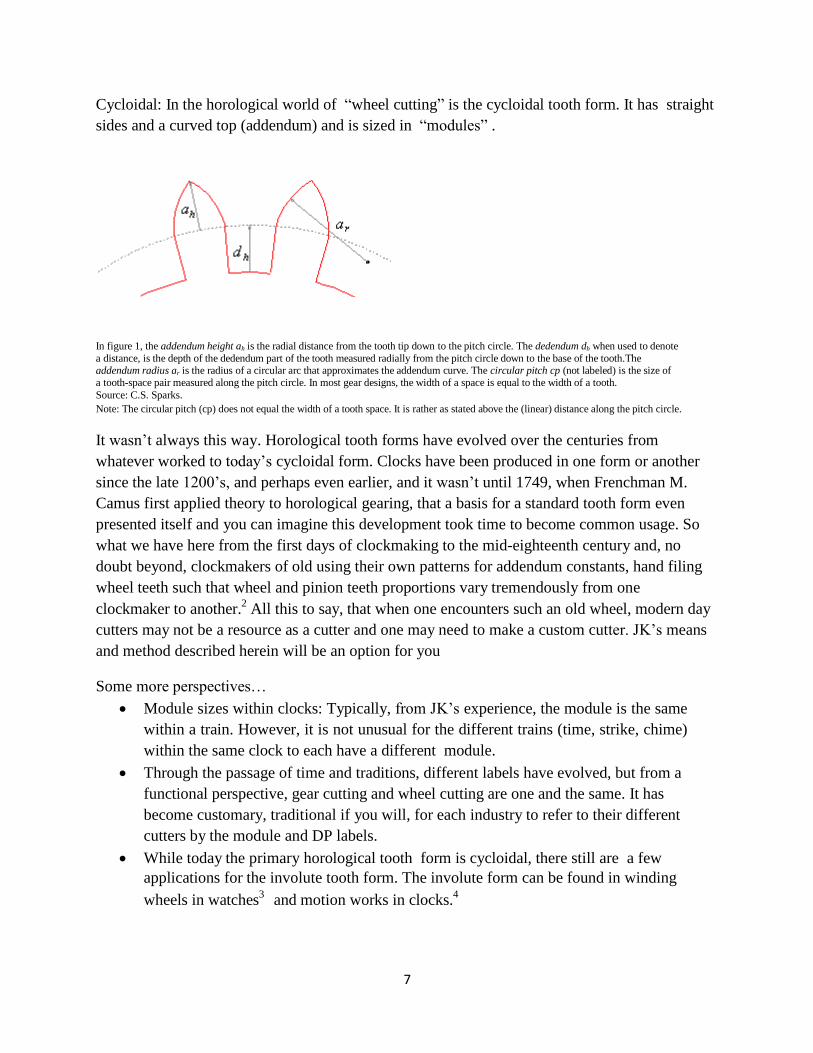
Cycloidal: In the horological world of “wheel cutting” is the cycloidal tooth form. It has straight
sides and a curved top (addendum) and is sized in “modules” .
In figure 1, the addendum height ah is the radial distance from the tooth tip down to the pitch circle. The dedendum dh when used to denote
a distance, is the depth of the dedendum part of the tooth measured radially from the pitch circle down to the base of the tooth.The addendum radius ar is the radius of a circular arc that approximates the addendum curve. The circular pitch cp (not labeled) is the size of a tooth-space pair measured along the pitch circle. In most gear designs, the width of a space is equal to the width of a tooth.
Source: C.S. Sparks.
Note: The circular pitch (cp) does not equal the width of a tooth space. It is rather as stated above the (linear) distance along the pitch circle.
It wasn’t always this way. Horological tooth forms have evolved over the centuries from
whatever worked to today’s cycloidal form. Clocks have been produced in one form or another
since the late 1200’s, and perhaps even earlier, and it wasn’t until 1749, when Frenchman M.
Camus first applied theory to horological gearing, that a basis for a standard tooth form even
presented itself and you can imagine this development took time to become common usage. So
what we have here from the first days of clockmaking to the mid-eighteenth century and, no
doubt beyond, clockmakers of old using their own patterns for addendum constants, hand filing
wheel teeth such that wheel and pinion teeth proportions vary tremendously from one
clockmaker to another.2
All this to say, that when one encounters such an old wheel, modern day
cutters may not be a resource as a cutter and one may need to make a custom cutter. JK’s means
and method described herein will be an option for you
Some more perspectives…
Module sizes within clocks: Typically, from JK’s experience, the module is the same
within a train. However, it is not unusual for the different trains (time, strike, chime)
within the same clock to each have a different module.
Through the passage of time and traditions, different labels have evolved, but from a
functional perspective, gear cutting and wheel cutting are one and the same. It has
become customary, traditional if you will, for each industry to refer to their different
cutters by the module and DP labels.
While today the primary horological tooth form is cycloidal, there still are a few
applications for the involute tooth form. The involute form can be found in winding
wheels in watches3
and motion works in clocks.4

8
In the geometry of teeth, the critical sections of the tooth are those sections that actually
touch, make contact/roll. Specifically, contact is primarily in the area where their pitch
circles meet. The rest of the tooth is designed for clearance.
Involute gear cutters cannot be used to cut cycloidal tooth forms and vice versa. Said
another way, DP cutters are not interchangeable with module cutters.
Finally, from George Daniels, is the best illustration and explanation I have found to help one
visualize the cycloidal curve43
.
“The Cycloidal Curve”
“The most suitable addendum for watch train wheels is derived from the cycloid curve generated
by a point at the edge of a circle rolling along a straight line. This is shown below in which the
circle A has rolled along line B for the Distance CD and the point P has traced the cycloid E.43
”
9
Cutters
Strict theory of cycloid curves…every change in wheel diameter and number of teeth would
require a different curve and height of addendum and therefore every change would require a
different cutter. However, less of the tip of the true curve is used and the constant addendum that
results from using the same cutter is acceptable for the different diameter of wheels and number
of teeth. Fortunately, for the same module, the difference in the theoretical tooth addendum
curves is small enough to allow the use of the same cutter for different diameter wheels.5
The strict theory was recognized as impractical, not economically feasible and, as indicated
above, not really necessary. So, at some point in time the gear and wheel cutting gurus got
together and agreed upon certain standards and averages. This is the basis for today’s
commercial sets of involute and horological cutters.
Cutters for the horological world of wheelcutting and non-horological world of gearing share a
design element whereby both are designed based on their number of teeth per inch. A key
difference resides in their cutter sets. In the horological world, for the same module, one cutter
representing an average, is used for the full range of wheel teeth i.e. different diameter wheels.
This average curve is deemed to be an acceptable curve shape for the full range of wheel teeth
within the same module. In the non-horological world, for the same DP, the involute gear has a
different cutter for a given range of teeth. I surmise this difference is allowed because of the
difference in their work environments. Clock wheel trains do not exert the amount of pressure
that a gear’s working environment would need to endure.
This difference is further illustrated below…
10
Commercial Cutters:
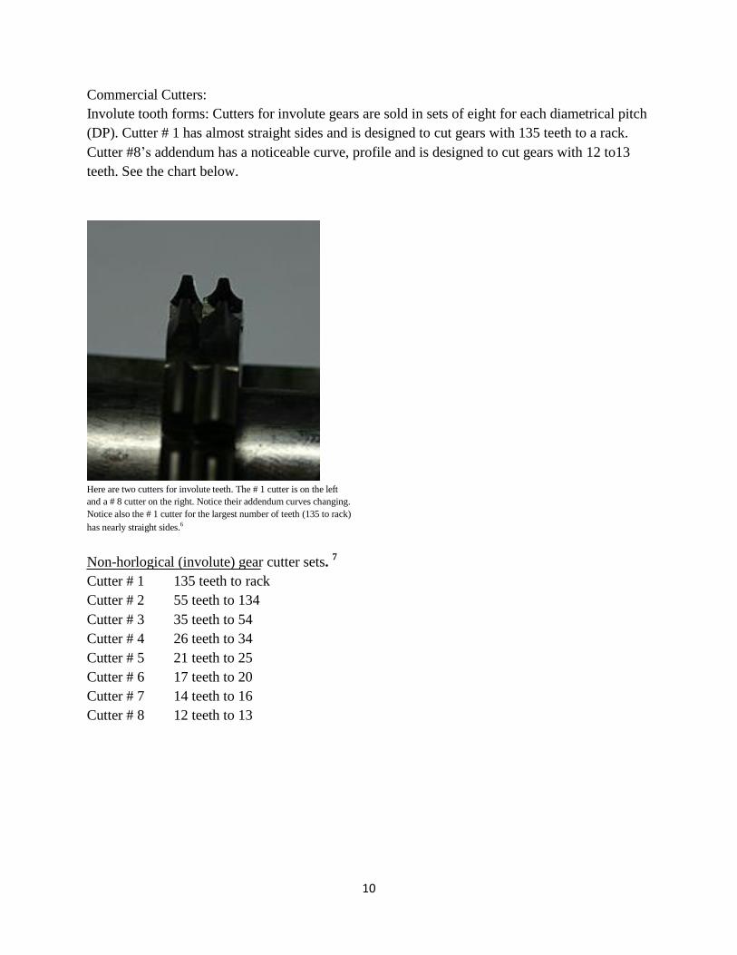
Involute tooth forms: Cutters for involute gears are sold in sets of eight for each diametrical pitch
(DP). Cutter # 1 has almost straight sides and is designed to cut gears with 135 teeth to a rack.
Cutter #8’s addendum has a noticeable curve, profile and is designed to cut gears with 12 to13
teeth. See the chart below.
Here are two cutters for involute teeth. The # 1 cutter is on the left
and a # 8 cutter on the right. Notice their addendum curves changing.
Notice also the # 1 cutter for the largest number of teeth (135 to rack)
has nearly straight sides.6
Non-horlogical (involute) gear cutter sets. 7
Cutter # 1 135 teeth to rack
Cutter # 2 55 teeth to 134
Cutter # 3 35 teeth to 54
Cutter # 4 26 teeth to 34
Cutter # 5 21 teeth to 25
Cutter # 6 17 teeth to 20
Cutter # 7 14 teeth to 16
Cutter # 8 12 teeth to 13
11
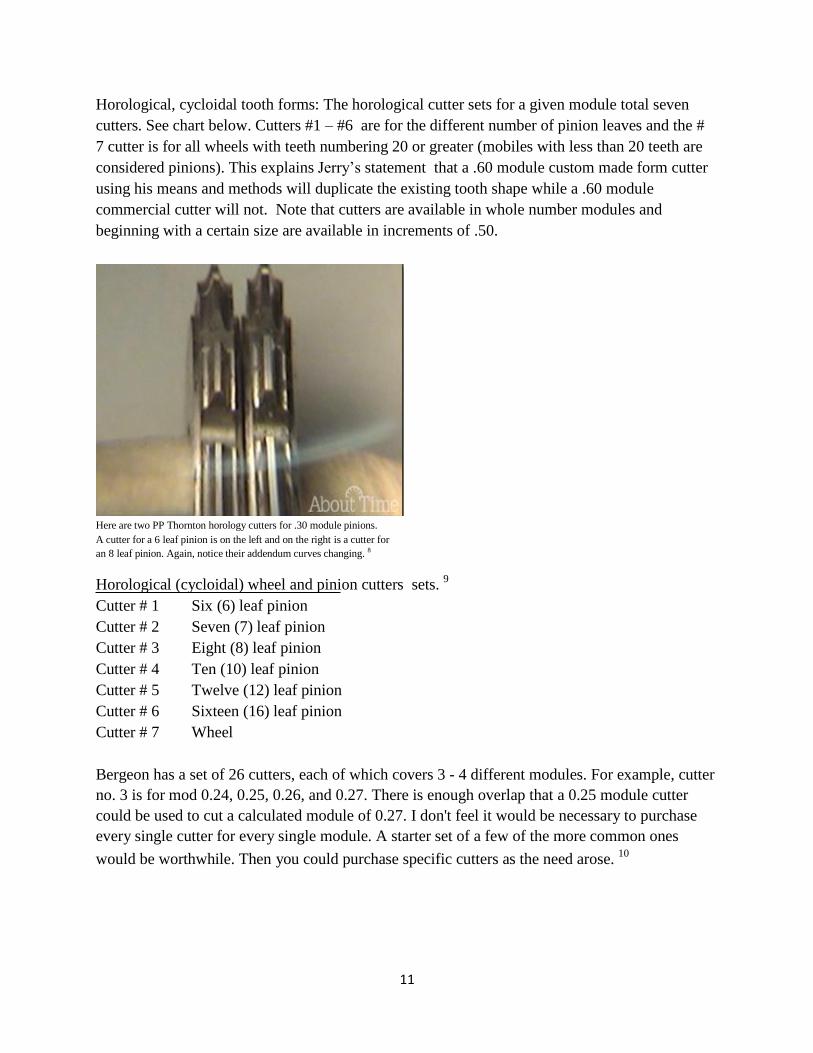
Horological, cycloidal tooth forms: The horological cutter sets for a given module total seven
cutters. See chart below. Cutters #1 – #6 are for the different number of pinion leaves and the #
7 cutter is for all wheels with teeth numbering 20 or greater (mobiles with less than 20 teeth are
considered pinions). This explains Jerry’s statement that a .60 module custom made form cutter
using his means and methods will duplicate the existing tooth shape while a .60 module
commercial cutter will not. Note that cutters are available in whole number modules and
beginning with a certain size are available in increments of .50.
Here are two PP Thornton horology cutters for .30 module pinions.
A cutter for a 6 leaf pinion is on the left and on the right is a cutter for
an 8 leaf pinion. Again, notice their addendum curves changing. 8
Horological (cycloidal) wheel and pinion cutters sets. 9
Cutter # 1 Six (6) leaf pinion
Cutter # 2 Seven (7) leaf pinion
Cutter # 3 Eight (8) leaf pinion
Cutter # 4 Ten (10) leaf pinion
Cutter # 5 Twelve (12) leaf pinion
Cutter # 6 Sixteen (16) leaf pinion
Cutter # 7 Wheel
Bergeon has a set of 26 cutters, each of which covers 3 - 4 different modules. For example, cutter
no. 3 is for mod 0.24, 0.25, 0.26, and 0.27. There is enough overlap that a 0.25 module cutter
could be used to cut a calculated module of 0.27. I don't feel it would be necessary to purchase
every single cutter for every single module. A starter set of a few of the more common ones
would be worthwhile. Then you could purchase specific cutters as the need arose. 10

12
Here it is in drawing form. The cutter on the left is for a 6 leaf pinion and the one on the right is
for an 8 leaf. The cutter for the 6 leaf pinion will cut a slightly shorter leaf than the cutter for the
8 leaf pinion. The 8 leaf pinion will also have flanks which are slightly more vertical. The space
between leaves will be slighter greater on the 8 leaf pinion than the 6 leaf.11
Flanks of the pinions change similar to how the addendum changes in the tooth…however…
For the same module, when increasing the number of leaves on a pinion i.e. 6-7-8-10-12-16. the
flank of the pinion changes shape similar to how the tooth addendum changes shape when the
number of wheel teeth are increased. This characteristic, however, is a more significant matter
with pinions than with wheels as evidenced in the design of commercial cutter sets. Instead of
having only one cutter for pinions like they do for wheels, there is a different cutter for almost
every change in number of pinion leaves…proof, if indeed we need it, that the flank changes in
the pinion present a larger issue with friction, required clearances and rolling contact then the
addendum changes do with teeth. For a deeper read on this, refer to Claudius Saunier’s “Treatise
on Modern Horology”. In the “Depths” section of his text, Saunier discusses this characteristic at
length, referring to it as “uniformity in the lead”.

13
Custom Single Point Cutters:
When needing to cut an involute gear or a horological wheel, home shop machinists have
essentially two choices…they can either purchase a commercial cutter or make a custom single
point cutter, otherwise known as a fly cutter. Jerry’s method for making a custom single point
cutter is really what these writings are all about. It is where his modern day machining breaks
away from the clockmaker traditions of the past.
Variety of custom single point cutters I’ve machined the JK way
There are a number of advantages to making a JK custom cutter vs. commercial cutter:
With an existing wheel, one is certain the original tooth shape functioned properly. Thus,
making a cutter exactly like the original tooth form ensures the wheel will mesh with its
mating pinion.
Tooth will look the same as its mates. That said, teeth that are not exactly like the
original can and do work, they mesh if you will. Just the same, one needs to target good
workmanship.
They are very cheap to make (once one has made the investment in the right machine
tools ). Conversely commercial cutters are very expensive and usually do not emulate
the original shape of the tooth form.
It is very easy to sharpen. Lay the flat side on the oiled India Stone and rub it back and
forth for 30 seconds or so. Conversely, commercial cutters are difficult to sharpen and
require an investment in more expensive sharpening tools.
These JK designed cutters are very sturdy and not subject to breakage such as oftentimes
occurs with some types of homemade single point cutters.27

14
After hardening, one can very readily remove the carbon. It comes off easily during the
sharpening process. Conversely, removing carbon from intricate areas, such as are
present in other fly cutter designs, is difficult at best. Even though I would use powdered
boric acid as a protective covering, carbon still gets into intricate areas and is difficult to
remove. Thus, another advantage of JK’s cutter design.
For reference, the use of powdered boric acid is based on John B. Moore’s July 16, 1916
patented method12
for using powdered boric acid for the hardening process. This method
discusses the use of water or heat to get the powder to stick to the metal. Archie Perkins
refers to this method in his book “The Modern Watchmakers Lathe and How to Use it”,
though he suggests the use of heat rather than water to get the powder to stick to the
metal. Actually using water instead of heat worked better for me. By the way, this
method is great for hardening pallets as it leaves minimal to no scale on the pallet
surfaces. My actual process is: dip the part into water, dip the wet part into the powder,
heat to cherry red, plunge into water. The powdered boric acid becomes glass hard hot
during the heating process and explodes off when it comes into contact with the water,
leaving the part’s surface with minimal to no scale. Ergo its reputation as a “protective
coating”.
A little more background: Heating metal pulls the chemical element carbon out of metal.
This is known as “decarbonization”. The carbon in this state is known as “scale” and is
visible on the metal surface and typically is hard to remove. Horologists vary in their
means and methods to contend with this condition.
A little More About DP and Modules:
Neither the information on DP nor the information on Modules are essential knowledge for
cutting wheels via the “JK Modern Means and Methods”, however, knowing this information
satisfies the curiosity and is simply good information for clockmakers to become familiar with. I
was even able to draw some keen perspective after having added these formulas to the “Wheel
Cutting Worksheet” (to be discussed later). It became apparent, that even though the Outside
Diameter and Pitch Diameter (all to be discussed shortly) could be off a few thousandths using
the calipers (dial, digital, Vernier) measuring method discussed below, it did not have an impact
on the DP or module calculation. Interpret that as the few thousandths error wasn’t sufficient to
change the round up or round down result. This was a helpful perspective, given that it is easy to
be a bit off with the calipers (dial, digital, vernier) because of tooth wear, a bent wheel or just
presenting the calipers at the wrong angle. Even placing the caliper jaw tips on tooth tips can be
a bit fiddly. Knowing this, one can seek to mitigate the error by taking several readings with
several opposing teeth, bend the wheel straight or straighter, etc. Remember if one is replacing
teeth or replacing a whole wheel, something is seriously wrong with the wheel to begin with and
repeated readings will contribute to good, repeatable outcomes.

15
One would need to know the Module or DP to purchase commercial cutters as all manufacturers
use Modules or DP to identify the different cutter “sizes”. Recognize, however, that neither the
DP nor the Module are an actual “size” per se…Rather it is a relationship between the number of
teeth and the pitch diameter. In the non-horological world, when gearing is calculated in inches,
DP represents the number of teeth per inch of pitch diameter. When wheels are calculated in
millimeters, Modules represent pitch diameter in millimeters divided by the number of teeth. To
convert one to the other...Remember 25.4.
For the longest time, I understood the module and DP numbers to be the size of the tooth space
a/k/a width of the tooth space. Instead these numbers represent a ratio relationship i.e. the # of
teeth per inch.
In those instances where one is making a clock from scratch and has no original
wheel or clock to use as a guide, the “module” is, in essence, a by-product of the
clockmakers intended design i.e. their intended BPH, tooth count, center distances,
duration, etc. That once one designs a clock they use these design configurations to
then calculate the modules. 13
Many old clocks have calculated modules that are not available as current wheel
cutters, the manufacturers simply did what they wanted to do. It is handy, however, to
use a design that allows one to use commercially available cutters so as to avoid the
need for making fly cutters. 14
While the module is not necessarily a choice or criteria for designing configurations,
one would do well to be mindful of the commercial cutter module sizes available
when designing clock trains for ease in wheel cutting. More to the point, as a matter
of practical application, machinists and gear cutters use the “diametrical pitch
system” as a reference point to design gears i.e. they work to the diametrical pitch. 15
This is understood to be the same for modern day horological design and wheel
cutters. Not so much for clockmakers of old. As stated above and in many other
references, they just did what worked. This fact speaks directly to the value and
significance of Jerry Kieffer’s modern means and method. As you will see from these
writings, Jerry teaches the concept of how to machine a custom single point cutter for
any horological tooth shape and size. This, as you will discover, is the key to
successful wheelcutting.

16
Mixing and matching cutters
Involute cutters - there is some flexibility for mixing manufacturer’s involute cutters. JK
says it best…”commercial wheel and pinion (involute) cutters for high speed heavy
loads, such as a large truck rear end, are generally designed in sets that are best purchased
from the same manufacturer. However, for non-critical, slow speed loads such as a
garden tractor transmission, brands with the same DP designation can generally be mixed
without issue”.16
Horological cutters – “because of the vast variation of tooth forms in horological
movements, all cutters should be visually compared to existing teeth to be duplicated”. 17
Of course, therein lies the challenge as typically the cutter you need is not in your tool
box and instead needs to be purchased. It is hard to compare when the cutter you need is
in a distant state or maybe even a distant land and they are not cheap. This would be
another advantage of developing the skill set of making your own single point cutters in
your shop. Note also that commercial cutters for wheels and pinions are intended to be
made as matched pairs. Thus, ideally, one would purchase them together.

17
Helpful tips for micro milling:
Lighting workpieces on mill table i.e. using reflective lighting. I’m not exactly sure what
lighting principle is at work here but if you’ve ever shined a light directly on the
workpiece, you’ll find it is hard to see. Using reflective light mitigates that situation. Try
this: 18
o Place stiff white paper of appropriate size behind the saddle
o Shine light on the paper
o Light reflects back onto the workpiece
Milling machine terminology and parts
o “X” axis is the table and is controlled by the “X” handwheel
Clockwise handwheel turns: table moves right to left
Counterclockwise handwheel turns: table moves left to right
o “Y” axis is the saddle and is controlled by the “Y” handwheel
Clockwise handwheel turns: saddle moves to the back away from the
operator
Counterclockwise handwheel turns: saddle moves to the front towards the
operator
o “Z” axis is the headstock/spindle controlled by the “Z” handwheel
Clockwise handwheel turns moves headstock/spindle down
Counterclockwise handwheel turns moves headstock/spindle up
o All three axis can move in .001” increments
Before machining, establish a habit of locking all axis (table, saddle and headstock) that
will not be moving. This is especially needed on a cutting task with a lot of force.
o The Sherline mill has a particularly helpful feature in this regard. When needing
to do precise machining make use of the brass lock lever on the “Z” axis. Move
the lever to the almost lock position. Snug it up if you will. This eliminates the
backlash for the task at hand.
Machining process and results are improved with:19
o Sharp end mills
o Rigid, stable end mills
o Cutting fluid, particularly for steel, but also for brass
o Locking all axis not moving before machining.
18
Milling any part brings with it significant cutting forces. Given this, items need to be very
secure and the machining process needs to be planned so as to produce the least amount of
force. In our instance of the cutter blank…its positioning in the center of the vice and the
guidance to progress the table from right to left so that the end mill progresses across the
top of the cutter blank are all intended to ease the stress on the workpiece and the machine.
Ultimately the workpiece (cutter blank) stays secure and results in a better finish.
An overall JK bit of advice…”if you don’t seem to grasp a particular tools and procedure
concept, move on to a different approach to achieve the same result, we all learn
differently”.
Horological wheel cutting makes extensive use of measurement tools. Thus, a couple of
points to make with regards to caliper measuring tools such as dial calipers, digital calipers
or Vernier Calipers. First, in each instance, these tools are only accurate to within
.001”- .002”. There are occasions in wheel cutting whereby one needs a more accurate reading. An example would be a wheel’s center hole. In such instances, one should use gage pins a/k/a pin gages instead of the calipers inside diameter jaws. For accurate outside diameters, one should use a micrometer. This is mentioned throughout the article. Note that these remarks are intended for diameters of ½” or less. At least for me, as beyond that calipers become the more practical tool and the .001” - .002” is of less consequence. For certain distance measurements the calipers are the only practical tool. An example would be a wheel’s outside diameter. In those instances, recognize that the caliper is only accurate to within .001” - .002”. Secondly, for the reader’s clarity, I only own a dial caliper, thus the readings throughout will refer to dial calipers. This should be understood to mean that references related to dial calipers are also intended to include digital calipers or Vernier Calipers.


![involute profile - [email protected]](https://cdn.vdocument.in/doc/165x107/62038846da24ad121e4a82be/involute-profile-emailprotected.jpg)