
17
Hot Forming Characteristics of Magnesium Alloy AZ31 and Three-Dimensional FE Modeling
and Simulation of the Hot Splitting Spinning Process
He Yang1, Liang Huang and Mei Zhan State Key Laboratory of Solidification Processing, School of Materials Science and
Engineering, Northwestern Polytechnical University, P.O.Box 542, Xi'an, 710072,
China
1. Introduction
As one kind of lightweight alloys in the widely applications, magnesium alloys are currently
the lightest structural materials with low density, high specific strength and specific
stiffness, superior damping capacity [Michael et al., 1999; Mordike & Ebert, 2001]. The
superior damping capacity is provided by the lower Young's modulus-E, and the value of E
is no sensitive to material microstructures. When a structural component of magnesium
alloy is subject to the same impact loadings, it can perform more elastic deformation and
absorb more impact energy. Besides, stress distributions inside of a structural component of
magnesium alloy are more uniform, thereby high stress concentrations can be avoided.
Therefore, a structural component of magnesium alloy subjected to the impact loadings can
be formed. Meanwhile, as one new continuous and local plastic forming technology,
splitting spinning is designed to split a revolving disk blank from the outer rectangular edge
into two flanges using a roller called splitting roller with a sharp corner, and then shaping
spinning is done by two or three other forming rollers [Wong et al., 2003; Wang & Liu,
1986], as shown in Fig. 1. Compared with other conventional methods combining with
casting, forging and welding and then mechanical processing, splitting spinning has the
remarkable advantages of high efficiency, low cost and good flexibility, and its products for
aeronautics, astronautics, automobile and weapon industry meet the high quality and high
precision demands and are developed at low costs in a short time [Yang et al., 2004; Song et
al., 2000]. Accordingly, based on the above remarkable advantages and application
foregrounds of magnesium alloy AZ31 and the above manufacturing predominance of
splitting spinning, a structure component of magnesium alloy AZ31 subjected to the impact
loadings and with high quality and high precision can be formed using splitting spinning,
such as, a wheel hub of aero undercarriage or kinds of light whole wheels.
According to the past research on deformation property of magnesium alloy, the ductility
and formability of magnesium alloy is low at room temperature due to its hexagonal close-
1 E-mail: [email protected]
www.intechopen.com

Magnesium Alloys - Design, Processing and Properties
368
a) before forming b) during the forming process c) shaping spinning
Fig. 1. Schematic illustration of splitting spinning
packed (HCP) crystal structure, so it is difficult to be deformed. However, it shows excellent
ductility and formability at elevated temperatures. Especially, magnesium alloy AZ31 is
characterized by a good formability and ductility at elevated temperature [Palumbo et al.,
2007]. The investigation by Ogawa et al. [Ogawa et al., 2002] indicated that the determination
of appropriate forming temperature of magnesium alloy AZ31 is one of key factors, thereby
the forming limit is improved and the fracture of specimen is avoided. The investigation by
Doege et al. [Doege & Droder, 2001] indicated that high forming limit of magnesium alloy
AZ31 could be obtained when the forming temperature exceeds 200˚C, on the contrary,
forming limit reduced and forming quality of a structural component decreased when forming
temperature reaches above 450˚C. Consequently, many recent research activities show that,
magnesium alloy AZ31 has the features of the high plastic formability from 200˚C to 450˚C,
and it can be deformed into a desired structural component.
Due to the limitation of experimental study and theoretical analysis, the investigations on the
distributions of stress, strain and temperature and the influencing laws of forming parameters
on forming quality are difficulties during metal forming processes. FE numerical simulation is
applied increasingly and is becoming a very important tool for the research on the field
distributions and forming quality of a structural component [Grass et al., 2003; Grass et al.,
2006]. At present, there are only some research on the FE numerical simulations of splitting
spinning. Based on the FE software DEFORM2D V5.02 and MARC/ Autoforge V1.2, Hauk et
al. [Hauk et al., 2000] studied the forming characteristics and rules of splitting spinning using
elastic-plastic FEM, and the mechanism and laws of geometric dimensions of disk blank and
friction influencing on deformation during the process are obtained under the two-
dimensional space. And then experimental research are performed by means of the
equipments called Tooling System, the influencing laws of different materials, different feed
rates and different splitting spinning angles on splitting spinning force during the process are
obtained [Schmoeckel & Hauk, 2000]. The deviation between two-dimensional simulation data
and experiment data is acceptable, so the results are usable. Nevertheless, the 3D FE model
reduced disk blank, simplified feeding mechanism system and ignored friction action between
disk blank and supporting roller during the forming process in order to reduce computational
time and improve computational efficiency. So, the above assumptions resulted in lower
computational precision, such as, the splitting spinning force in simulations was less than the
one in experiments, about one half. So in order to obtain more accurate simulation results, a
reliable and practical 3D FE model of splitting spinning should be established.
The authors have studied the cold splitting spinning process of aluminium alloy. A reliable
and practical 3D-FE model of cold splitting spinning of aluminium alloy is established, and
www.intechopen.com

Hot Forming Characteristics of Magnesium Alloy AZ3 and Three-Dimensional FE Modeling and Simulation of the Hot Splitting Spinning Process
369
the variations of spinning force, stress fields and strain fields with time are obtained
[Huang1 et al., 2008]. The influencing laws of forming parameters of splitting spinning on
the quality and precision of flanges are investigated based on the forming characteristics of
splitting spinning combining with the behaviors of roller [Huang et al., 2009]. The
influencing laws of material parameters on splitting spinning force, splitting spinning
moment and forming quality of flange have been investigated [Huang2 et al., 2008]. A
reliable theoretical model established by the principal stress method is proposed for the
calculation of splitting spinning force, and the influencing laws of forming parameters on
splitting spinning force are investigated [Huang3 et al., 2008]. However, the research on hot
splitting spinning of magnesium alloy AZ31 is scant by now, so the above results may help
study hot splitting spinning of magnesium alloy AZ31.
In this paper, according to the analysis of microstructures and deformation characteristics of
magnesium alloy AZ31, the reasonable forming temperature range is obtained during the
thermoplastic forming process. A three-dimentional elastic-plastic FE model of hot splitting
spinning of magnesium alloy AZ31 is established based on the FEM software platform of
ABAQUS/ Explicit and a developed three-dimensional FE model of cold splitting spinning,
and then the reliability is verified by theoretical evaluation. The modeling procedures are
summarized, the comparisons of the modeling process between hot splitting spinning and
traditional spinning are presented, and some key technologies are proposed. Adopting the
FE model, field distributions of deformed component, including temperature fields, stress
fields and strain fields, and variations of different nodal temperature are obtained, and the
influencing laws of different initial temperatures of disk blank and different feed rates of
splitting roller on the forming quality and precision of deformed flanges are investigated,
consequently the optimal forming temperature and the optimal feed rate of splitting roller
during the hot splitting spinning process of magnesium alloy AZ31 are obtained.
2. Hot forming characteristics of magnesium alloy AZ31
The deformation mechanisms of magnesium alloy mainly contain twinning and slip, and
deformation texture roots in basal slips among grain boundaries [Staroselsky & Anand,
2003; Chino1 et al., 2008; Chino2 et al., 2008]. All these deformation mechanisms and texture
characteristics affect plastic deformation behaviors, formability and mechanical property of
magnesium alloy strongly. During the hot splitting spinning process, magnesium alloy
AZ31 (Mg–3mass%Al–1%massZn–0.5%massMn) disk blank is mainly extruded, so
microstructures of the extrusion specimen for different forming temperatures must be
realized in order to obtain the optimal forming temperature range and forming parameters.
Thermal mechanical property of magnesium alloy AZ31 is quite related to processing
technology, heat treatment process and so on, especially for different forming temperatures,
thermal mechanical property of magnesium alloy AZ31 varies on a large scope. Therefore,
according to the analysis of microstructures and deformation characteristics of magnesium
alloy AZ31, hot forming characteristics are obtained. And then the forming rules during the
hot splitting spinning process of magnesium alloy AZ31 under tensile stress and
compressive stress simultaneously is revealed and the optimal forming parameters and
forming temperature range are obtained.
According to excellent ductility and formability of magnesium alloy AZ31 at elevated
temperatures and forming temperature variation from 200˚C to 450˚C, there are two kinds of
specimen [Chino2 et al., 2008], which are the extrusion magnesium alloy AZ31 processed by
www.intechopen.com
Magnesium Alloys - Design, Processing and Properties
370
extruding at 500˚C is called the sample A (above the high temperature variation ) and the
extrusion magnesium alloy AZ31 processed by extruding at 210˚C is called the sample B
(within high temperature variation). Fig. 2 is shown as microstructure of magnesium alloy
AZ31 specimen, (a) sample A and (b) sample B. Usually, the plasticity or ductility of
magnesium alloy AZ31 is low at room temperature, but at elevated temperatures, plastic
deformation energy is activated among grains and grain boundaries, so the plasticity and
forming limit are improved. For magnesium alloy AZ31, forming temperature must be
controlled from 200˚C to 450˚C. Because plastic deformation energy is inactivated among
grains and grain boundaries below 200˚C, and disk blank of magnesium alloy AZ31 may
brittle fracture easily, nevertheless, when temperature is above 450˚C, disk blank of
magnesium alloy AZ31 may be oxide etch and grain size may become large, even phase
transformation arises and plasticity decreases, as shown in Fig. 2(a). According to Fig. 2, it
can be found that, microstructure of sample A shows large grain size obviously and the
average grain size is 71 mμ for sample A, and microstructure of sample B shows close and
small grain size and the average grain size is 8 mμ for sample B.
According to the above analysis of microstructures, the twin interfaces energy of
magnesium alloy AZ31 is significantly large and twin nucleation decreases with decreasing
grain size. The plasticity and formability of magnesium alloy AZ31 is low and the response
of plastic deformation is inadequacy below 200˚C. But when magnesium alloy AZ31 is at
elevated temperatures, the plastic deformation energy transforms internal energy and the
forming process is done successfully and well, consequently the requirement of close and
small grain size in a whole structural component is satisfied. Meanwhile, it is necessary to
control the upper limit of forming temperature in order to avoid oxide etch and large grain
size inside of the whole structural component of magnesium alloy AZ31, even phase
transformation.
Furthermore, due to dynamic recovery (DRV) and dynamic recrystallization (DRX),
deformation magnesium alloy shows distinct high temperature softening during the hot
forming process. The strain softening is the typical characteristic of the elevated flow stress
model of magnesium alloys, whose material response can principally be divided into two
categories during the hot forming process, DRV type and DRX type. For magnesium alloy
AZ31, DRX is the main characteristic of flow stress curves [Liu et al., 2008]. And also, the
temperature of dynamic recrystallization (DRX) of magnesium alloy AZ31 is approximate
from 533K to 593K [Liu et al., 2008].
According to the above microstructures and deformation characteristics of magnesium alloy
AZ31 with the characteristics of homogeneous and isotropic elastic-plastic body,
magnesium alloy AZ31 shows excellent ductility and plasticity when forming temperature
ranges from 200 ˚Cto 450˚C. Therefore, plastic deformation mechanisms of magnesium alloy
AZ31 and research foundations of hot splitting spinning of magnesium alloy AZ31 are
obtained.
3. FE modeling process of hot splitting spinning of magnesium alloy AZ31
3.1 Establishment of FE model of hot splitting spinning of magnesium alloy AZ31 During the hot splitting spinning process of magnesium alloy AZ31, two Mandrels rotate at
a rotational speed of ω , and SplittingRoller feeds at a linear speed of v in the radial
www.intechopen.com

Hot Forming Characteristics of Magnesium Alloy AZ3 and Three-Dimensional FE Modeling and Simulation of the Hot Splitting Spinning Process
371
direction of Diskblank. Meanwhile, under the effects of the friction between Diskblank and
SplittingRoller and the extrusions of two Mandrels, Diskblank is split into two flanges from
the outer rectangular edge using SplittingRoller with a sharp corner, which come into the
gaps at the joints between SplittingRoller and two Mandrels. After the forming ends, the
radius of Diskblank reduces, and two flanges are produced. According to the forming
characteristics of hot splitting spinning of magnesium alloy AZ31, Diskblank is defined as a
3D deformable solid body, SplittingRoller is defined as an analytical rigid body, and two
Mandrels are defined as discrete rigid bodies. Each rigid body is assigned with a reference
point (RP) to represent its rigid motion in all degrees of freedom. In materials Property
module, the model gives the denty, Young's modulus, Poisson's ratio, constitutive equations
and some thermal constants to material Diskblank which is a homogeneous and isotropic
elastic-plastic body, and the model follows von Mises yield criterion and shear friction
model [Yu & Chen, 1999].
Fig. 2. Microstructure of magnesium alloy AZ31 extrusions, (a) sample A and (b) sample
B[Chino2 et al., 2008]
The heat transfer during the hot splitting spinning process of magnesium alloy AZ31 is a
very complicated coupled thermo-mechanical problem. During the hot forming process, the
free surface of disk blank exchanges heat with external environment by means of convection
and radiation, and the contact surface conducts heat to the dies. Meanwhile, the plasticity
deformation energy of disk blank is mostly converted into heat energy and internal energy.
In order to define the thermal-dependent contacts among bodies and position them relative
to each other in only one global coordinate system in which workpiece and dies would be
identical with practical places during the hot forming process, some thermal-dependent
contact surfaces and three thermal-dependent contact pairs are defined [Huang1 et al., 2008].
The study arranges only one step called Splitting-Process in simulations, meanwhile, sets a
suitable mass scaling factor in order to improve the computational efficiency. Moreover,
here are the output requests, including Field output requests and History output requests,
which contain stress, strain, displacement, force, temperature and energy of the whole
model or special elements.
Consequently in this study, based on the FEM software platform of ABAQUS/ Explicit, a
three-dimentional elastic-plastic FE model of hot splitting spinning of magnesium alloy
AZ31 is established, as shown in Fig. 3.
www.intechopen.com

Magnesium Alloys - Design, Processing and Properties
372
3.2 Key technologies treatments during the modeling process 3.2.1 Determination of exact forming time During the 3D FE simulation process of hot splitting spinning of magnesium alloy AZ31,
how to make sure the exact forming time is one of key factors which can exactly predict and
control the hot forming process. Therefore, this study deduces a formula including velocity,
displacement and time, as follows.
Fig. 3. Three-dimensional elastic-plastic FE model of hot splitting spinning of magnesium
alloy AZ31 under ABAQUS/ Explicit.
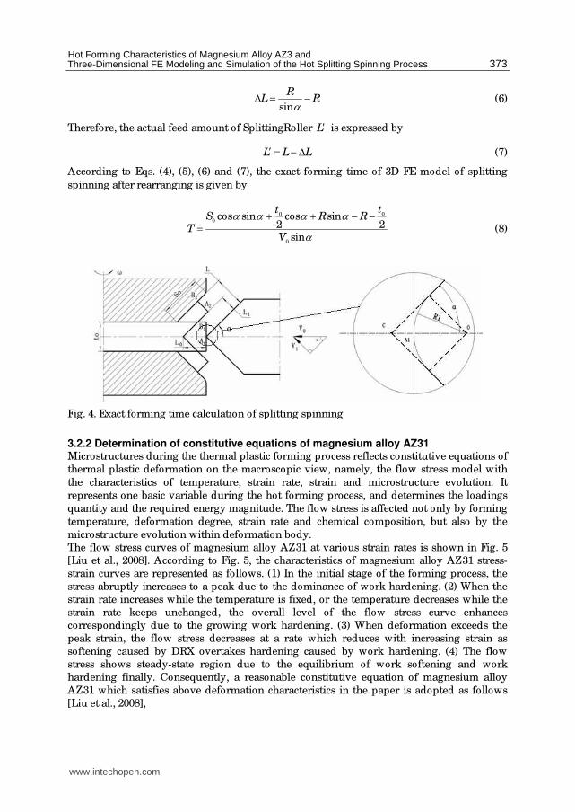
It is shown as the exact forming time calculation of splitting spinning in Fig. 4. According to
Fig. 4, the ending face 1 1
A B indicated by the thin broken lines before the forming translates
to the ending face 2 2
A B indicated by the broad real lines after the forming. Therefore, along
the feeding direction of SplittingRoller, a formula is given as,
0 0
L V T= (1)
where 0
L is the feed amount of SplittingRoller, 0
V is the feed rate of SplittingRoller, T is
the forming time. Similarly, along the other feeding direction, a formula is given as,
1 1
L V T= (2)
where 1
L is the other feed amount of SplittingRoller, 1
V is the other feed rate of
SplittingRoller. Meanwhile, according to velocity vector analysis in Fig. 4, we obtain that
1 01
0 0 0
2sin
L T L tV
V V V Tα −= = = (3)
And the displacement L is obtained by
0
0cos sin cos
2
tL S α α α= + (4)
Therefore, substitution of Eqs. (4) into Eq. (3), the forming time T is expressed by
0 0 0
0
2 cos sin cos
2 sin
S t tT
V
α α αα
+ −= (5)
Due to the round corner of SplittingRoller sticking to circumferential surface of the
workpiece, the actual feed amount of SplittingRoller is less than the displacement 0
L , as
shown in right enlarged view of Fig. 4. So the displacement LΔ is obtained by
www.intechopen.com
Hot Forming Characteristics of Magnesium Alloy AZ3 and Three-Dimensional FE Modeling and Simulation of the Hot Splitting Spinning Process
373
sin
RL RαΔ = − (6)
Therefore, the actual feed amount of SplittingRoller L′ is expressed by
L L L′ = − Δ (7)
According to Eqs. (4), (5), (6) and (7), the exact forming time of 3D FE model of splitting
spinning after rearranging is given by
0 0
0
0
cos sin cos sin2 2
sin
t tS R R
TV
α α α αα
+ + − −= (8)
Fig. 4. Exact forming time calculation of splitting spinning
3.2.2 Determination of constitutive equations of magnesium alloy AZ31 Microstructures during the thermal plastic forming process reflects constitutive equations of
thermal plastic deformation on the macroscopic view, namely, the flow stress model with
the characteristics of temperature, strain rate, strain and microstructure evolution. It
represents one basic variable during the hot forming process, and determines the loadings
quantity and the required energy magnitude. The flow stress is affected not only by forming
temperature, deformation degree, strain rate and chemical composition, but also by the
microstructure evolution within deformation body.
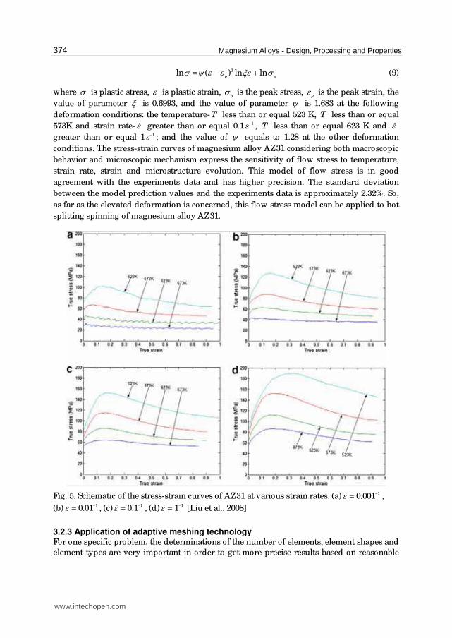
The flow stress curves of magnesium alloy AZ31 at various strain rates is shown in Fig. 5
[Liu et al., 2008]. According to Fig. 5, the characteristics of magnesium alloy AZ31 stress-
strain curves are represented as follows. (1) In the initial stage of the forming process, the
stress abruptly increases to a peak due to the dominance of work hardening. (2) When the
strain rate increases while the temperature is fixed, or the temperature decreases while the
strain rate keeps unchanged, the overall level of the flow stress curve enhances
correspondingly due to the growing work hardening. (3) When deformation exceeds the
peak strain, the flow stress decreases at a rate which reduces with increasing strain as
softening caused by DRX overtakes hardening caused by work hardening. (4) The flow
stress shows steady-state region due to the equilibrium of work softening and work
hardening finally. Consequently, a reasonable constitutive equation of magnesium alloy
AZ31 which satisfies above deformation characteristics in the paper is adopted as follows
[Liu et al., 2008],
www.intechopen.com
Magnesium Alloys - Design, Processing and Properties
374
2ln ( ) ln lnp p
σ ψ ε ε ξε σ= − + (9)
where σ is plastic stress, ε is plastic strain, p
σ is the peak stress, pε is the peak strain, the
value of parameter ξ is 0.6993, and the value of parameter ψ is 1.683 at the following
deformation conditions: the temperature- T less than or equal 523 K, T less than or equal
573K and strain rate- ε$ greater than or equal 0.1 1s− , T less than or equal 623 K and ε$
greater than or equal 1 1s− ; and the value of ψ equals to 1.28 at the other deformation
conditions. The stress-strain curves of magnesium alloy AZ31 considering both macroscopic
behavior and microscopic mechanism express the sensitivity of flow stress to temperature,
strain rate, strain and microstructure evolution. This model of flow stress is in good
agreement with the experiments data and has higher precision. The standard deviation
between the model prediction values and the experiments data is approximately 2.32%. So,
as far as the elevated deformation is concerned, this flow stress model can be applied to hot
splitting spinning of magnesium alloy AZ31.
Fig. 5. Schematic of the stress-strain curves of AZ31 at various strain rates: (a) 10.001ε −=$ ,
(b) 10.01ε −=$ , (c) 10.1ε −=$ , (d) 11ε −=$ [Liu et al., 2008]
3.2.3 Application of adaptive meshing technology For one specific problem, the determinations of the number of elements, element shapes and
element types are very important in order to get more precise results based on reasonable
www.intechopen.com
Hot Forming Characteristics of Magnesium Alloy AZ3 and Three-Dimensional FE Modeling and Simulation of the Hot Splitting Spinning Process
375
computational fees. During the 3D FE modeling process of hot splitting spinning of
magnesium alloy AZ31, elements must own not only appreciable rigidity called anti-
distorting ability, but also appreciable flexibility called good forming ability [ABAQUS
(version 6.4), 2004]. Therefore, adaptive meshing technology is used to avoid the element
distortion and large deformation.
Adaptive meshing technology is a tool makes it possible to maintain a high-quality mesh
throughout the analysis, even when large deformation or loss of material occurs, by
allowing the mesh to move independently of material. According to a comparison between
distorted elements without adaptive meshing technology and normal elements with
adaptive meshing technology, practical deformation can be simulated by using adaptive
mesh technology [Huang1 et al., 2008]. Adaptive meshing technology in ABAQUS does not
change the topology of the mesh, and combines the features of pure Lagrangian analysis
and pure Eulerian analysis. This type of adaptive meshing is named Arbitrary Lagrangian
Eulerian (ALE) analysis.
Therefore, the FE model makes use of adaptive meshing technology in order to reduce
element distortion and maintain good element aspect ratios. The domain using adaptive
meshing technology is defined as Diskblank, and then the definition of the boundary
smoothing region is followed that: initial feather angle is 30˚, transition feather angle is also
30°, and mesh constraint angle is 60°. These settings can guarantee high computational
efficiency in simulation computation. Meanwhile, in the settings of adaptive meshing
technology, different remeshing frequencies may bring to different simulation results. For
instance, there is almost no significant for the spinning force at different remeshing
frequencies, but there is a significant deviation for the maximum equivalent plastic strain
rate at different remeshing frequencies. Thus, in order to eliminate the impact on simulation
results at different remeshing frequencies, the model uses remeshing sweeps after everyone
increment, and define a suitable remeshing frequency.
3.2.4 Definition of frictional type and constraint type The hot splitting spinning process of magnesium alloy AZ31 belongs to a continuous local
plastic forming process, and the plastic forming area focuses on a small circumferential area
of Diskblank. Friction behaviors during the hot forming process have particular
characteristics: (1) friction between SplittingRoller and Diskblank is a main force driving the
plastic forming, companying with material plastic movement, and (2) friction between
flanges and exteriors of SplittingRoller or surfaces of mandrels produces along with the hot
forming process, which holds back presentation of flanges and influences surface roughness
of flanges. Therefore, based on the above frictional characteristics, the FE model calculates
friction force by using the shear friction mode.
Constraint between mandrels and Diskblank cannot cause the plastic deformation, but may
cause the elastic deformation at the beginning of the hot splitting spinning process of
magnesium alloy AZ31. Diskblank rotates with mandrels, and deforms with SplittingRoller
feedings. In ABAQUS, the types of constraints contain tie, rigid body, display body,
coupling, shell-tosolid coupling, embedded region and equation [ABAQUS (version 6.4),
2004]. Therefore, based on above forming characteristics, one constraint called Tie is
adopted to link Diskblank with mandrels due to the fact that Diskblank must rotate with
mandrels. Tie can integrate mandrels with Diskblank as a whole, and provide them with
different meshing methods, especially three-dimensional meshing.
www.intechopen.com

Magnesium Alloys - Design, Processing and Properties
376
3.3 Verification of FE model of hot splitting spinning of magnesium alloy AZ31 The FE model is reliable and reasonable based on the validation of the past research
[Huang1 et al., 2008]. Due to joining the thermal analysis procedure, it is necessary for hot
splitting spinning of magnesium alloy AZ31 to carry out the theoretical evaluation
[ABAQUS (version 6.4), 2004]. In order to indicate the FE simulation results being a
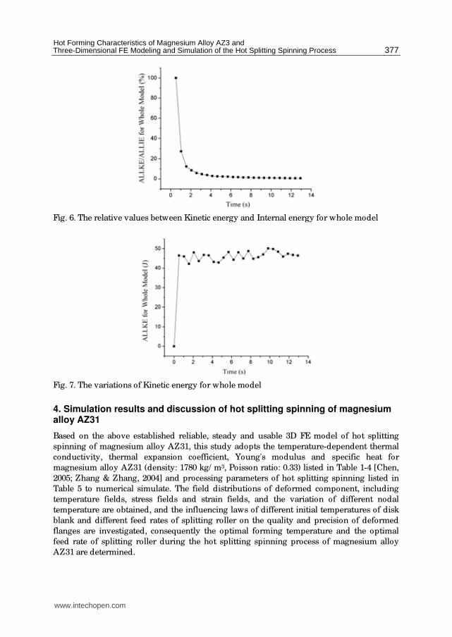
receivable quasi-static solution, there are two main criteria, (1) when kinetic energy of
deformation materials don't exceed approximately 5% to 10% of internal energy during the
mostly simulation time, the adoptive mass scaling factor is reasonable, and (2) in order to
obtain smooth solutions, it is necessary to validate whether the curve of kinetic energy is
adequately smooth.
The relative values between Kinetic energy (ALLKE) and Internal energy (ALLIE) for whole
model is shown in Fig. 6. According to Fig. 6, at the steady forming stage, the relative values
between Kinetic energy and Internal energy is less than 5% obviously, so the curve satisfies
the first criterion. The variations of Kinetic energy for whole model are shown in Fig. 7.
According to Fig. 7, the Kinetic energy reaches a peak value in a short time, and then keeps
steady state all the time, so the curve satisfies the second criterion. Therefore, the 3D elastic-
plastic coupled thermo-mechanical FE model of hot splitting spinning of magnesium alloy
AZ31 is reliable, steady and usable.
3.4 Characteristics of FE model The comparisons of the modeling process between hot splitting spinning of magnesium
alloy AZ31 and traditional spinning are as follows in this paper.
1. As Diskblank is extruded into the deformation zone step by step and then departs from
the deformation zone after the flanges are manufactured, elastic-plastic FE method is
adopted to control the elastic recovery of Diskblank in the modeling process of hot
splitting spinning of magnesium alloy AZ31. But the rigid-plastic FE method is usually
adopted in the modeling process of traditional spinning.
2. In the choice of FE arithmetic, a dynamic explicit algorithm in simulation of hot
splitting spinning of magnesium alloy AZ31 is the same as the one in simulation of
traditional spinning. The choice can avoid the characteristic of not-constringency by
using a dynamic implicit algorithm.
3. In the definition of boundary conditions, since the angle between roller and blank is an
important processing parameter and the roller-traces are variable, displacement
boundary conditions are adopted in the definition of mechanics conditions of
traditional spinning. But the angle between SplittingRoller and Diskblank is 0˚ and the
roller-trace is unique during the hot splitting spinning process of magnesium alloy
AZ31. Therefore, the velocity boundary conditions are adopted in the definition of
mechanics conditions of hot splitting spinning of magnesium alloy AZ31.
4. In the element choice and meshing, triangle shell elements are usually adopted to study
numerical simulations of traditional spinning, and the meshing are random. Only one
element is modeled in the thickness. In this paper, due to hot splitting spinning belongs
to the bulk deformation, hexahedral brick elements are adopted, which are the
temperature-dependent quadratic reduced-integration elements (C3D8RT). These
elements are not susceptible to locking, even when subjected to complicated states of
stress. Therefore, these elements are also generally the best choice for the most general
temperature-stress-displacement simulations. In meshing, concentric circle meshing
mode is adopted in order to avoid hourglass modes. Furthermore, in the generation of
flanges along axial direction, meshing is symmetrical.
www.intechopen.com
Hot Forming Characteristics of Magnesium Alloy AZ3 and Three-Dimensional FE Modeling and Simulation of the Hot Splitting Spinning Process
377
Fig. 6. The relative values between Kinetic energy and Internal energy for whole model
Fig. 7. The variations of Kinetic energy for whole model
4. Simulation results and discussion of hot splitting spinning of magnesium alloy AZ31
Based on the above established reliable, steady and usable 3D FE model of hot splitting
spinning of magnesium alloy AZ31, this study adopts the temperature-dependent thermal
conductivity, thermal expansion coefficient, Young's modulus and specific heat for
magnesium alloy AZ31 (density: 1780 kg/ m3, Poisson ratio: 0.33) listed in Table 1-4 [Chen,
2005; Zhang & Zhang, 2004] and processing parameters of hot splitting spinning listed in
Table 5 to numerical simulate. The field distributions of deformed component, including
temperature fields, stress fields and strain fields, and the variation of different nodal
temperature are obtained, and the influencing laws of different initial temperatures of disk
blank and different feed rates of splitting roller on the quality and precision of deformed
flanges are investigated, consequently the optimal forming temperature and the optimal
feed rate of splitting roller during the hot splitting spinning process of magnesium alloy
AZ31 are determined.
www.intechopen.com

Magnesium Alloys - Design, Processing and Properties
378
Temperature, ˚C Thermal conductivity, W/ (m⋅˚C)
96.4 25
101 100
105 200
109 300
113 400
Table 1. Thermal conductivity of magnesium alloy AZ31
Temperature,˚C Expansion coefficient,˚C -1
100 2.64E-005
200 2.7E-005
300 2.79E-005
Table 2. Thermal expansion coefficient of magnesium alloy AZ31
Temperature,˚C Young's modulus, GPa
20 40.2
75 37.3
100 34.3
125 30.9
150 30.4
200 29.4
250 27.5
Table 3. Young's modulus of magnesium alloy AZ31
Temperature,˚C Specific Heat, J/ (kg⋅˚C)
20 1050
100 1130
200 1170
300 1210
350 1260
Table 4. Specific Heat of magnesium alloy AZ31
www.intechopen.com
Hot Forming Characteristics of Magnesium Alloy AZ3 and Three-Dimensional FE Modeling and Simulation of the Hot Splitting Spinning Process
379
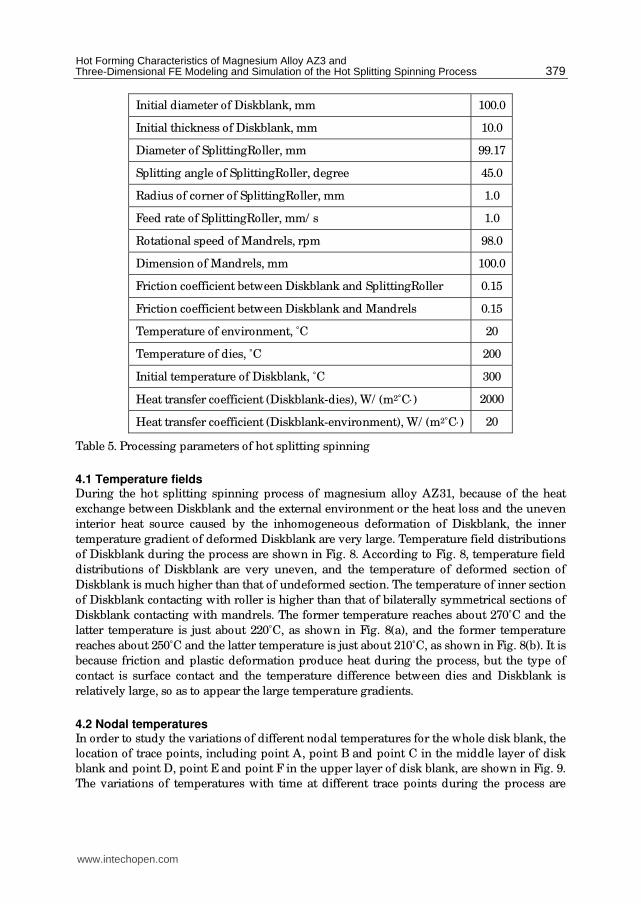
Initial diameter of Diskblank, mm 100.0
Initial thickness of Diskblank, mm 10.0
Diameter of SplittingRoller, mm 99.17
Splitting angle of SplittingRoller, degree 45.0
Radius of corner of SplittingRoller, mm 1.0
Feed rate of SplittingRoller, mm/ s 1.0
Rotational speed of Mandrels, rpm 98.0
Dimension of Mandrels, mm 100.0
Friction coefficient between Diskblank and SplittingRoller 0.15
Friction coefficient between Diskblank and Mandrels 0.15
Temperature of environment, ˚C 20
Temperature of dies, ˚C 200
Initial temperature of Diskblank, ˚C 300
Heat transfer coefficient (Diskblank-dies), W/ (m2˚C⋅) 2000
Heat transfer coefficient (Diskblank-environment), W/ (m2˚C⋅) 20
Table 5. Processing parameters of hot splitting spinning
4.1 Temperature fields During the hot splitting spinning process of magnesium alloy AZ31, because of the heat
exchange between Diskblank and the external environment or the heat loss and the uneven
interior heat source caused by the inhomogeneous deformation of Diskblank, the inner
temperature gradient of deformed Diskblank are very large. Temperature field distributions
of Diskblank during the process are shown in Fig. 8. According to Fig. 8, temperature field
distributions of Diskblank are very uneven, and the temperature of deformed section of
Diskblank is much higher than that of undeformed section. The temperature of inner section
of Diskblank contacting with roller is higher than that of bilaterally symmetrical sections of
Diskblank contacting with mandrels. The former temperature reaches about 270˚C and the
latter temperature is just about 220˚C, as shown in Fig. 8(a), and the former temperature
reaches about 250˚C and the latter temperature is just about 210˚C, as shown in Fig. 8(b). It is
because friction and plastic deformation produce heat during the process, but the type of
contact is surface contact and the temperature difference between dies and Diskblank is
relatively large, so as to appear the large temperature gradients.
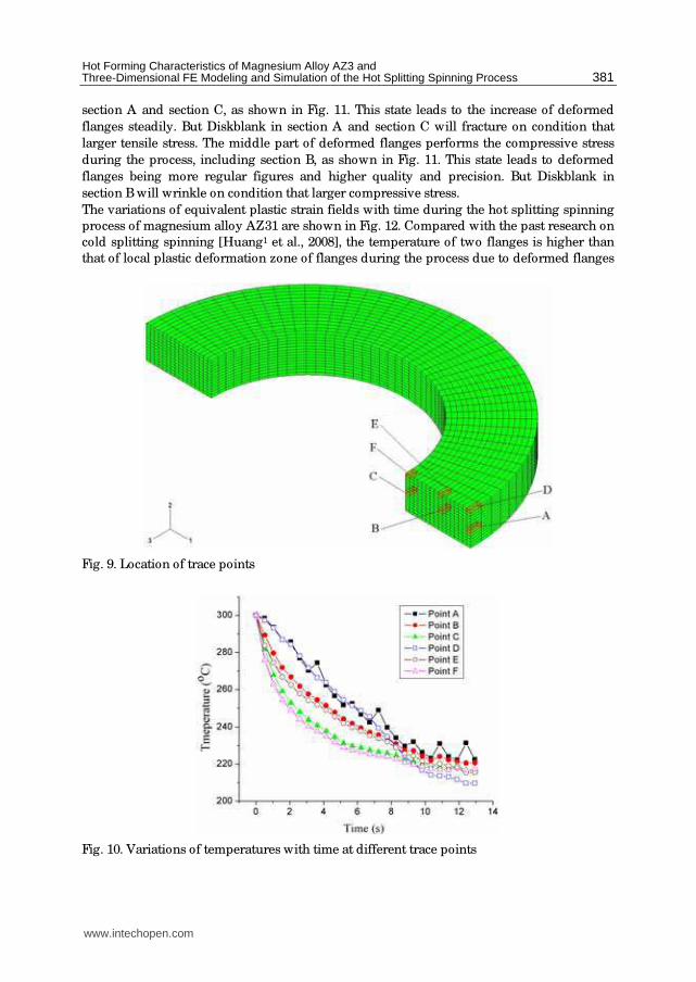
4.2 Nodal temperatures In order to study the variations of different nodal temperatures for the whole disk blank, the
location of trace points, including point A, point B and point C in the middle layer of disk
blank and point D, point E and point F in the upper layer of disk blank, are shown in Fig. 9.
The variations of temperatures with time at different trace points during the process are
www.intechopen.com

Magnesium Alloys - Design, Processing and Properties
380
shown in Fig. 10. From Fig. 10, the temperature variations between point A and point D is
similar, so do point B and point E as well as point C and point F. Point A and point D are
both the trace points of outer circumferential surface of disk blank, but point A contacting
with roller in the middle layer belongs to local plastic deformation zone and point D
contacting with mandrels in the upper layer belongs to deformed flanges zone. Although
the curves between point A and point D are similar, the temperature of point A reaches one
extremum at intervals at the ending stage of the process and the extremum is a little more
than that of point D. Because at the ending stage of the process, the deformation heat leads
to ascend at intervals at point A after the temperature of point A goes down to about 240˚C.
Besides, point A obtains the contact heat, radiation and friction heat, so that the temperature
of point A is more than that of point D. Because of higher temperature of Diskblank, heat
exchange exists between dies and environment. There is no enough time to exchange heat
with the outside at the beginning of simulation, but as the simulation going on, external
temperature of Diskblank descends, so there is a temperature gradient between inside and
outside of Diskblank leading to the heat is transferred to the outside of Diskblank.
(a)step=12,time=6.206s. (b)step=25,time=12.93s.
Fig. 8. Temperature field distributions of Diskblank
The curve of point B is extremely similar to the curve of point E and the curve of point C is
also extremely similar to the curve of point F, but the temperature of point B is a little more
than that of point E and the temperature of point C is a little more than that of point F. The
point in the middle layer of disk blank lies on the local plastic deformation zone, so more
deformation heat is obtained. For the temperature distributions in the same layer of disk
blank, the temperature of point A is more than that of point B and the temperature of point
B is more than that of point C, and meanwhile the temperature of point D is more than that
of point E and the temperature of point E is more than that of point F. The reasons are that,
the deformation of outside circumferential zone is larger, and meanwhile the deformation
energy and friction heat is larger than heat transferred from the surface to the environment.
So, the temperature of point A and that of point D are relatively higher.
4.3 Strain fields The logarithmic strain vector distributions at the ending stage of deformation are shown in
Fig. 11. The logarithmic strain can reflect the accumulative effects of plastic deformation and
metal flow directions. Therefore, the upper surface of deformed flanges contacting with
mandrels and the under surface of deformed flanges contacting with roller both perform the
tensile stress during the hot splitting spinning process of magnesium alloy AZ31, including
www.intechopen.com
Hot Forming Characteristics of Magnesium Alloy AZ3 and Three-Dimensional FE Modeling and Simulation of the Hot Splitting Spinning Process
381
section A and section C, as shown in Fig. 11. This state leads to the increase of deformed
flanges steadily. But Diskblank in section A and section C will fracture on condition that
larger tensile stress. The middle part of deformed flanges performs the compressive stress
during the process, including section B, as shown in Fig. 11. This state leads to deformed
flanges being more regular figures and higher quality and precision. But Diskblank in
section B will wrinkle on condition that larger compressive stress.
The variations of equivalent plastic strain fields with time during the hot splitting spinning
process of magnesium alloy AZ31 are shown in Fig. 12. Compared with the past research on
cold splitting spinning [Huang1 et al., 2008], the temperature of two flanges is higher than
that of local plastic deformation zone of flanges during the process due to deformed flanges
Fig. 9. Location of trace points
Fig. 10. Variations of temperatures with time at different trace points
www.intechopen.com

Magnesium Alloys - Design, Processing and Properties
382
Fig. 11. Logarithmic strain vector distributions at the ending stage of deformation: A-Red, B-
Blue, C-Yellow
contacting with both roller and mandrels. Consequently, there are two symmetrical belts in
which equivalent strain distributions are uniform and even, as shown in Fig. 12(b). Furthermore, due to the thermal plastic deformation, the maximum equivalent plastic strain
of hot splitting spinning is more than the maximum equivalent plastic strain of cold splitting
spinning.
(a)step=12,time=6.206s. (b)step=25,time=12.93s.
Fig. 12. The variations of equivalent plastic strain fields with time
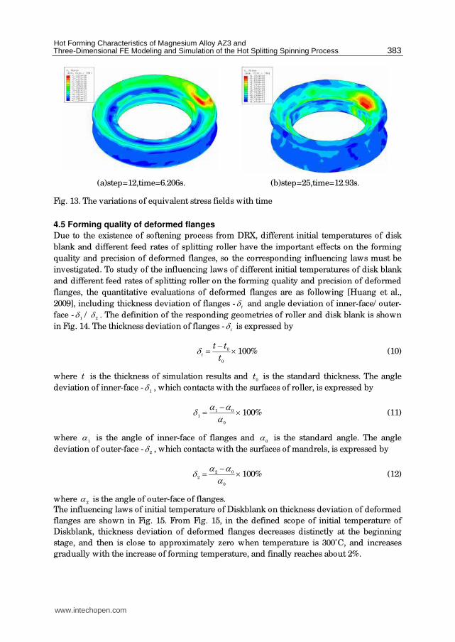
4.4 Stress fields The variations of equivalent stress fields with time during the hot splitting spinning process
of magnesium alloy AZ31 are shown in Fig. 13. From Fig.13, compared with the past
research on cold splitting spinning [Huang1 et al., 2008], stress concentration are not
presented in the local plastic deformation zone contacting with roller due to the existence of
softening process from DRX. There are enough heat for DRX in the upper surface of disk
blank, therefore stress concentration are presented in the zone contacting with mandrels.
Furthermore, the figure of stress concentration zone isn't like a belt, only a corresponding
section contacting with local plastic deformation zone.
www.intechopen.com
Hot Forming Characteristics of Magnesium Alloy AZ3 and Three-Dimensional FE Modeling and Simulation of the Hot Splitting Spinning Process
383
(a)step=12,time=6.206s. (b)step=25,time=12.93s.
Fig. 13. The variations of equivalent stress fields with time
4.5 Forming quality of deformed flanges
Due to the existence of softening process from DRX, different initial temperatures of disk
blank and different feed rates of splitting roller have the important effects on the forming
quality and precision of deformed flanges, so the corresponding influencing laws must be
investigated. To study of the influencing laws of different initial temperatures of disk blank
and different feed rates of splitting roller on the forming quality and precision of deformed
flanges, the quantitative evaluations of deformed flanges are as following [Huang et al.,
2009], including thickness deviation of flanges -t
δ and angle deviation of inner-face/ outer-
face -1
δ /2
δ . The definition of the responding geometries of roller and disk blank is shown
in Fig. 14. The thickness deviation of flanges -t
δ is expressed by
0
0
100%t
t t
tδ −= × (10)
where t is the thickness of simulation results and 0
t is the standard thickness. The angle
deviation of inner-face -1
δ , which contacts with the surfaces of roller, is expressed by
1 0
1
0
100%α αδ α
−= × (11)
where 1
α is the angle of inner-face of flanges and 0
α is the standard angle. The angle
deviation of outer-face -2
δ , which contacts with the surfaces of mandrels, is expressed by
2 0
2
0
100%α αδ α
−= × (12)
where 2
α is the angle of outer-face of flanges.
The influencing laws of initial temperature of Diskblank on thickness deviation of deformed
flanges are shown in Fig. 15. From Fig. 15, in the defined scope of initial temperature of
Diskblank, thickness deviation of deformed flanges decreases distinctly at the beginning
stage, and then is close to approximately zero when temperature is 300˚C, and increases
gradually with the increase of forming temperature, and finally reaches about 2%.
www.intechopen.com

Magnesium Alloys - Design, Processing and Properties
384
The influencing laws of initial temperature of Diskblank on angle deviation of deformed
flanges are shown in Fig. 16. From Fig. 16, in the defined scope of initial temperature of
Diskblank, the angle deviation of outer-face is a little more than that of inner-face, and they
remain with the similar curves. The curves decrease distinctly at the beginning stage, and
then increase gradually with the increase of forming temperature. When temperature is
300˚C, both angle deviations of deformed flanges are close to approximately zero
simultaneously.
The influencing laws of feed rate of splitting roller on thickness deviation of deformed
flanges are shown in Fig. 17. From Fig. 17, in the defined scope of feed rate of splitting roller,
there are three phases for the changing curve. When 1v < mm/ s, thickness deviation of
deformed flanges increases distinctly and is negative. When 1 3v≤ ≤ mm/ s, thickness
deviation holds approximately zero. When 3v > mm/ s, thickness deviation increases
gradually and are positive, and the value is more than 4%.
Fig. 14. The definition of the responding geometries of roller and disk blank
Fig. 15. The influencing laws of initial temperature of Diskblank on thickness deviation
www.intechopen.com

Hot Forming Characteristics of Magnesium Alloy AZ3 and Three-Dimensional FE Modeling and Simulation of the Hot Splitting Spinning Process
385
Fig. 16. The influencing laws of initial temperature of Diskblank on angle deviation
Fig. 17. The influencing laws of feed rate of splitting roller on thickness deviation
The influencing laws of feed rate of splitting roller on angle deviation of deformed flanges
are shown in Fig. 18. From Fig. 18, in the defined scope of feed rate of splitting roller, when
1v < mm/ s, angle deviation of deformed flanges increases suddenly and are negative, and
the values are less than –8%; when 1 3v≤ ≤ mm/ s, angle deviation hold approximately
from 0 to 2%; when 3v > mm/ s, angle deviation increases gradually, and angle deviation of
inner-face reaches above 2% and angle deviation of outer-face reaches above 4%.
The above two quantitative evaluations of deformed flanges are relatively larger values
when temperature is about 200˚C, namely, for initial temperature of Diskblank, thickness
deviation is more than 6%, angle deviation of inner-face is more than 9% and angle
deviation of outer-face is more 5%, and meanwhile for feed rate of splitting roller, thickness
deviation is less than –5%, angle deviation of inner-face and outer-face are both less than
www.intechopen.com

Magnesium Alloys - Design, Processing and Properties
386
Fig. 18. The influencing laws of feed rate of splitting roller on angle deviation
–9%. And when temperature is about 450˚C, the above two quantitative evaluations of
deformed flanges become even and steady, but larger values, namely, for initial temperature
of Diskblank, thickness deviation is more than 4%, angle deviation of inner-face is more
than 6% and angle deviation of outer-face is more 5%, and meanwhile for feed rate of
splitting roller, thickness deviation is more than 6%, angle deviation of inner-face and outer-
face are both less than 4%. Only when forming temperature is about 300˚C, the above two
quantitative evaluations of deformed flanges are close to zero. The reasons are that, strain
hardening and softening from DRX keeps an appropriate balance during the hot splitting
spinning process of magnesium alloy AZ31 when temperature is about 300˚C, so here
thickness deviation is minor and angle deviation is close to zero, and forming quality and
precision are highest. In the same way, when the feed rate of splitting roller is defined from
1 to 3mm/ s, forming quality and precision are also highest during the hot splitting spinning
process of magnesium alloy AZ31. Consequently, the optimal forming temperature is
approximate 300˚C and the optimal feed rate of splitting roller ranges from 1 to 3mm/ s
during the hot splitting spinning process of magnesium alloy AZ31.
5. Conclusions
In this paper, hot forming characteristics of magnesium alloy AZ31 are analyzed and a
reasonable deformation temperature range is obtained during the thermoplastic forming
process. Based on the FEM software platform of ABAQUS/ Explicit and a developed three-
dimensional FE model of cold splitting spinning, a three-dimensional elastic-plastic FE
model of hot splitting spinning of magnesium alloy AZ31 is established, and the forming
characteristics and laws are as follows.
1. During the hot splitting spinning process of magnesium alloy AZ31, temperature field
distributions of Diskblank are very uneven, and the temperature of inner section of
Diskblank contacting with roller is higher than that of bilaterally symmetrical sections
of Diskblank contacting with mandrels, so there is a temperature gradient between
inside and outside of Diskblank.
www.intechopen.com

Hot Forming Characteristics of Magnesium Alloy AZ3 and Three-Dimensional FE Modeling and Simulation of the Hot Splitting Spinning Process
387
2. During the process, section A and section C (Fig. 11) perform the tensile stress, and this
state leads to the increase of deformed flanges steadily; section B (Fig. 11) performs the
compressive stress, and this state leads to deformed flanges being more regular figures
and higher quality and precision. There are two symmetrical uniform belts in the
equivalent strain distributions, and the stress concentration is presented in only one
section contacting with mandrels.
3. The optimal forming temperature is approximate 300˚C and the optimal feed rate of
splitting roller ranges from 1 to 3mm/ s during the hot splitting spinning process of
magnesium alloy AZ31.
6. Acknowledgements
The authors would like to thank the National Natural Science Foundation of China (Nos.
50405039 and 50575186), the National Science Found of China for Distinguished Young
Scholars (No. 50225518), the National "863" Project of China (No. 2008AA04Z122) and the
Foundation of NWPU (No. W018104) for the support given to this research.
7. References
ABAQUS (version 6.4) (2004). ABAQUS Analysis User’s Manual, Inc.
Chen Zhenhua (2005). Deformation Magnesium Alloys, Chemical Industry Press, Beijing (in
Chinese)
Chino1 Yasumasa, Kimura Katsuya, Hakamada Masataka & Mabuchi Mamoru
(2008).Mechanical anisotropy due to twinning in an extruded AZ31 Mg alloy,
Mater. Sci. Eng. A, 485, 311–317
Chino2 Yasumasa, Kimura Katsuya & Mabuchi Mamoru (2008) Twinning behavior and
deformation mechanisms of extruded AZ31 Mg alloy, Mater. Sci. Eng. A, 486, 481–
488
Doege E. & Droder K. (2001). Sheet metal forming of magnesium wrought alloys —
formability and process technology, J. Mater. Process. Technol., 115, 14–19
Grass H., Krempaszky C., Reip T. & Werner E. (2003). 3-D Simulation of hot forming and
microstructure evolution, Comput. Mater. Sci., 28, 469–477
Grass H., Krempaszky C. & Werner E. (2006). 3-D FEM-simulation of hot forming processes
for the production of a connecting rod, Comput. Mater. Sci., 36, 480–489
Hauk Stefan, Vazquez Victor H. & Altan Taylan (2000). Finite element simulation of the
Flow-Splitting-Process, J. Mater. Process. Technol., 98,70–80
Huang1 Liang, Yang He & Zhan Mei (2008). 3D-FE modeling method of splitting spinning,
Comput. Mater. Sci., 42, 643–652
Huang2 Liang, Yang He, Zhan Mei & Hu Li-jin (2008). Numerical simulation of influence of
material parameters on splitting spinning of aluminum alloy, Trans. Nonferrous Met.
Soc. China, 18, 674–681
Huang3 Liang, Yang He, Zhan Mei & Yuli Liu (2008). Analysis of splitting spinning force by
the principal stress method, J. Mater. Process. Technol., 201, 267–272
Huang Liang, Yang He, Zhan Mei & Lijin Hu (2009). Forming characteristics of splitting
spinning based on the behaviors of roller, Comput. Mater. Sci., 45, 449–461
www.intechopen.com
Magnesium Alloys - Design, Processing and Properties
388
Liu Juan, Cui Zhenshan & Li Congxing (2008). Modelling of flow stress characterizing
dynamic recrystallization for magnesium alloy AZ31B, Comput. Mater. Sci. 41, 375–
382
Michael M. , Avedesian & Baker, Hugh (1999). Magnesium and Magnesium Alloys, ASM
Specialty Handbook, USA
Mordike B. L. & Ebert T. (2001). Magnesium Properties — applications — potential, Mater.
Sci. Eng. A, 302, 37–45
Ogawa N., Shiomi M. & Osakada K. (2002). Forming limit of magnesium alloy at elevated
temperatures for precision forging, Int. J. Mach. Tools Manuf., 42, 607–614.
Palumbo G., Sorgente D., Tricarico L., Zhang S. H. & Zheng W. T. (2007). Numerical and
experimental investigations on the effect of the heating strategy and the punch
speed on the warm deep drawing of magnesium alloy AZ31, J. Mater. Process.
Technol., 191, 342–346
Schmoeckel Dieter & Hauk Stefan (2000). Tooling and process control for splitting of disk
blanks, J. Mater. Process. Technol., 98, 65–69
Song Y. H., Zhang K. F., Wang Z. R. & Diao F. X. (2000). 3-D FEM analysis of the
temperature field and the thermal stress for plastics thermalforming, J. Mater.
Process. Technol., 97, 35–43
Staroselsky A. & Anand L. (2003). A constitutive model for hcp materials deforming by slip
and twinning: application to magnesium alloy AZ31B, Int. J. Plast., 19, 1843–1864
Wang Chenghe & Liu Kezhang (1986). Spinning Technology, China Machine Press, Beijing (in
Chinese)
Wong C. C., Dean T. A. & Lin J. (2003). A review of spinning, shear forming and flow
forming process, Int. J. Mach. Tools Manuf., 43, 1419–1435
Yang H., Zhan M., Liu Y. L., Xian F. J., Sun Z. C., Lin Y. & Zhang X. G. (2004). Some
advanced plastic processing technologies and their numerical simulation, J. Mater.
Process. Technol., 151, 63–69
Yu Hanqing & Chen Jinde (1999). The principle of metal plastic forming, China Machine Press,
Beijing (in Chinese)
Zhang Jin & Zhang Zonghe (2004). Magnesium Alloy and Its Application, Chemical Industry
Press, Beijing (in Chinese)
www.intechopen.com

Magnesium Alloys - Design, Processing and PropertiesEdited by Frank Czerwinski
ISBN 978-953-307-520-4Hard cover, 526 pagesPublisher InTechPublished online 14, January, 2011Published in print edition January, 2011
InTech EuropeUniversity Campus STeP Ri Slavka Krautzeka 83/A 51000 Rijeka, Croatia Phone: +385 (51) 770 447 Fax: +385 (51) 686 166www.intechopen.com
InTech ChinaUnit 405, Office Block, Hotel Equatorial Shanghai No.65, Yan An Road (West), Shanghai, 200040, China
Phone: +86-21-62489820 Fax: +86-21-62489821
Scientists and engineers for decades searched to utilize magnesium, known of its low density, for light-weighting in many industrial sectors. This book provides a broad review of recent global developments intheory and practice of modern magnesium alloys. It covers fundamental aspects of alloy strengthening,recrystallization, details of microstructure and a unique role of grain refinement. The theory is linked withelements of alloy design and specific properties, including fatigue and creep resistance. Also technologies ofalloy formation and processing, such as sheet rolling, semi-solid forming, welding and joining are considered.An opportunity of creation the metal matrix composite based on magnesium matrix is described along withcarbon nanotubes as an effective reinforcement. A mixture of science and technology makes this book veryuseful for professionals from academia and industry.
How to referenceIn order to correctly reference this scholarly work, feel free to copy and paste the following:
He Yang, Liang Huang and Mei Zhan (2011). Hot Forming Characteristics of Magnesium Alloy AZ31 andThree-Dimensional FE Modeling and Simulation of the Hot Splitting Spinning Process, Magnesium Alloys -Design, Processing and Properties, Frank Czerwinski (Ed.), ISBN: 978-953-307-520-4, InTech, Available from:http://www.intechopen.com/books/magnesium-alloys-design-processing-and-properties/hot-forming-characteristics-of-magnesium-alloy-az31-and-three-dimensional-fe-modeling-and-simulation

© 2011 The Author(s). Licensee IntechOpen. This chapter is distributedunder the terms of the Creative Commons Attribution-NonCommercial-ShareAlike-3.0 License, which permits use, distribution and reproduction fornon-commercial purposes, provided the original is properly cited andderivative works building on this content are distributed under the samelicense.


