
AJ PerezCEO, NVBOTS
How to think like a 3D designer:
A practical guide to additive manufacturing

AJ Perez CEO
b BS in Mechanical Engineering and
Masters of Engineering in
Manufacturing from MIT
b Co-developed and lectures Additive
Manufacturing class at MIT
b Guest lectures at MIT, Stanford, BNU,
KIT, and BU
b Boston Globe 25 Innovators Under 25
b Jerome Lemelson inventor fellow

Introduction to additive manufacturing
Overview of conventional DFMA
What is DFAM and how is it different?
Design rules and guidelines by manufacturing process
Case studies in DFAM
AM process characterization
Future work in AM process optimization
Agenda

4
OVERVIEW
Selective Laser Sintering (SLS) is an additive
manufacturing technique that uses a laser as the
power source to sinter powdered material (typically
metal), aiming the laser automatically at points in
space defined by a 3D model, binding the material
together to create a solid structure.
MATERIAL CAPABILITIES
b Stainless Steel
b Cobalt Chrome
b Titanium
b Inco
b Maraging Steel
b Aluminium
Selective laser sintering (SLS)

5
OVERVIEW
Stereolithography (SLA) is an additive manufacturing
process which employs a vat of liquid
ultraviolet curable photopolymer "resin" and an
ultraviolet laser to build parts' layers one at a time. For
each layer, the laser beam traces a cross-section of
the part pattern on the surface of the liquid resin.
Exposure to the ultraviolet laser light cures and
solidifies the pattern traced on the resin and joins it to
the layer below. CLIP is a high speed SLA process
which leverages DLP technology to parallelize SLA.
MATERIAL CAPABILITIES
b Liquid polymer resin
CONFIDENTIAL DO NOT DISTRIBUTE
Copyright © 2015 New Valence® Robotics Corporation
Stereolithography (SLA) / Continuous liquid interface production (CLIP)

6
OVERVIEW
Fused Deposition Modeling (FDM) works on an
"additive" principle by laying down material in layers; a
plastic filament or metal wire is unwound from a coil
and supplies material to produce a part, by extruding
small beads of thermoplastic material to form layers as
the material hardens immediately after extrusion from
the nozzle.
MATERIAL CAPABILITIES
b Acrylonitrile Butadiene Styrene (ABS)
b Polylactic acid (PLA)
b Polycarbonate (PC)
b Polyamide (PA)
b Polystyrene (PS)
b Lignin
b Rubber
Fused deposition modeling (FDM)

Introduction to additive manufacturing
Overview of conventional DFMA
What is DFAM and how is it different?
Design rules and guidelines by manufacturing process
Case studies in DFAM
AM process characterization
Future work in AM process optimization
Agenda

Conventional Design for Manufacturing and Assembly (DFMA)
from Boothroyd
• Use modular subassemblies
• Use as many multifunctional parts as possible
• Use self-selecting features
• Minimize number and types of parts for assembly
• Minimize the use of fasteners
• Minimize operations and process steps
• Minimize part reorientation
• Avoid difficult to handle components
• Avoid special tooling/test equipment
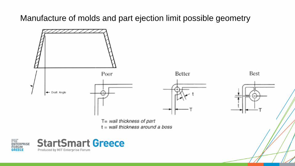
Manufacture of molds and part ejection limit possible geometry

Designers must avoid certain features that cause common defects
Voids Warping
Sink Marks Internal Stresses

Sheet metal and turning minimum feature size determined by radius of tool

Milling internal feature geometry limited by endmill radius

Introduction to additive manufacturing
Overview of conventional DFMA
What is DFAM and how is it different?
Design rules and guidelines by manufacturing process
Case studies in DFAM
AM process characterization
Future work in AM process optimization
Agenda

Subtractive
• Reduced fixturing
• Internal Features
• Undercuts
• Fixtures Required
• No Internal
Features
Additive
Minimize amount of material laid down each layer;
maximize strength to weightMinimize amount of material
removed from stock
Optimization
Problem
Optimization
Problem
DFAM vs conventional DFM

Why does DFAM matter and why should we care?

• Process Limitations
• Minimum Feature Size
• Limiting Process Parameters
• Software Limitations
• Materials
• Material Characteristics
• Mechanical Properties of the Part
• Geometric Design
• Macrostructure
• Orientation
• Support Structures
Framework to think about DFAM: Perez, Thomas, Feldmann

Introduction to additive manufacturing
Overview of conventional DFMA
What is DFAM and how is it different?
Design rules and guidelines by manufacturing process
Case studies in DFAM
AM process characterization
Future work in AM process optimization
Agenda

FDM & SLS Support structure 45 degree “rule of thumb”

Extrusion flow
rate
[volume/time]
X,Y linear speed [distance/time]
Acceptable error band;
slope must = ideal
Too Thick
Too Thin
FDM process quality must be carefully controlled if you want
precise features

Real world example of FDM extrusion control problem
Stratasys Mojo

Strong Weak
Force Force
Print orientation affects bulk and local mechanical properties

Process type Process
resolution
Support type Post processing Process limiting
variable(s)
Overhangs
SLA ~25μm Break away UV curing; thermal Energy flux on
mirror
45 degrees
FDM ~150μm Break away or
dissolvable
Surface treatments;
Infusion
Extrudate
diameter
45 degrees
SLS ~25μm Powder Thermal;
Infusion
Laser spot size Supported
Ink Jet ~20μm Break away UV curing Minimum droplet
size
45 degrees
Powder
binding
~25μm Powder Infusion Powder size;
droplet size
Supported
High level cross-process DFAM comparison

● Removal of support material
○ Ultrasonic water bath
● Surface finish
○ Bead blasting
○ Mass finishing
○ Finishing Touch smoothing-
cool and cut
○ Vapor polishing
○ Lapping
● Sealing/coating
○ Electroplating
○ Painting
○ Epoxy infiltration
○ Dipping
● Assembly of sections
○ Bonding and gluing
Designers must consider the effects that post processing
have on cycle time and dimensional accuracy

Introduction to additive manufacturing
Overview of conventional DFMA
What is DFAM and how is it different?
Design rules and guidelines by manufacturing process
Case studies in DFAM
AM process characterization
Future work in AM process optimization
Agenda

25
GE Turbine
Fuel Injectors
CO NVENTI ONAL ADDI T I VE
20 Components 1 Components
19 Assembly 0 Assembly
39 QC Steps 1 QC Steps
~25% weight reduction
~8% gain in fuel efficiency
DFAM case study: General Electric improves product
performance and reduces supply chain costs

26
NASA Turbine
Fuel Injectors
CO NVENTI ONAL ADDI T I VE
115 Components 2 Components
114 Assembly 1 Assembly
229 QC Steps 3 QC Steps
DFAM case study: NASA reduces part count >98%

Introduction to additive manufacturing
Overview of conventional DFMA
What is DFAM and how is it different?
Design rules and guidelines by manufacturing process
Case studies in DFAM
AM process characterization
Future work in AM process optimization
Agenda

Effect of print parameters on dimensional accuracy, weight, and print time are
a non-linear function.
Perez et al.
Characterizing tensile loading responses of 3D printed samples.
Christopher Haid
Force required to remove part from FDM machine.
Mateo Pena Doll
Recent work done at MIT to characterize FDM
Haid, Christopher. Characterizing tensile loading responses of 3D printed samples. MIT thesis.
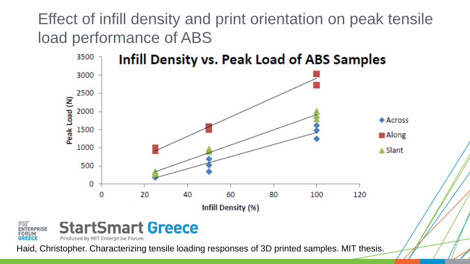
Effect of infill density and print orientation on peak tensile
load performance of ABS

Haid, Christopher. Characterizing tensile loading responses of 3D printed samples. MIT thesis.
Effect of infill density and print orientation on peak tensile
load performance of PLA

Haid, Christopher. Characterizing tensile loading responses of 3D printed samples. MIT thesis.
Effect of infill density and print orientation on stiffness of ABS

Haid, Christopher. Characterizing tensile loading responses of 3D printed samples. MIT thesis.
Effect of infill density and print orientation on stiffness of PLA

Pena Doll, Mateo. Part removal of 3D printed parts. MIT thesis.
Effect of print bed temp. on force required to remove part

Pena Doll, Mateo. Part removal of 3D printed parts. MIT thesis.
Effect of extrusion temp. on force required to remove part

Pena Doll, Mateo. Part removal of 3D printed parts. MIT thesis.
Effect of first layer thickness on force required to remove part

Introduction to additive manufacturing
Overview of conventional DFMA
What is DFAM and how is it different?
Design rules and guidelines by manufacturing process
Case studies in DFAM
AM process characterization
Future work in AM process optimization
Agenda

Confidential / Copyright © 2015 New
Valence Robotics Corporation 37
SELECT A PART
PRINT PREVIEW & CLOUD SLICING
QUEUE MANAGEMENT & CONTROL
AUTOMATED PRINTING
USE 3D PRINTED CURRICULUM
b More than 100 expert approved lesson plans
b More than 850 3D models
3D printing is an ecosystem, not just hardware

Confidential / Copyright © 2015 New
Valence Robotics Corporation 38
SELECT A PART
PRINT PREVIEW & CLOUD SLICING
QUEUE MANAGEMENT & CONTROL
AUTOMATED PRINTING
USE 3D PRINTED CURRICULUM
b First cloud 3D print preview
b Cloud based 3D printer drivers
b Enables mobile 3D printing
NVBOTS has the first cloud 3D printer system

Confidential / Copyright © 2015 New
Valence Robotics Corporation 39
SELECT A PART
PRINT PREVIEW & CLOUD SLICING
QUEUE MANAGEMENT & CONTROL
AUTOMATED PRINTING
USE 3D PRINTED CURRICULUM
b Verify every part is approved by admin
b Simple drag-and-drop control
NVBOTS has the only multi-user 3D printer
Confidential / Copyright © 2015 New
Valence Robotics Corporation 40
SELECT A PART
PRINT PREVIEW & CLOUD SLICING
QUEUE MANAGEMENT & CONTROL
AUTOMATED PRINTING
USE 3D PRINTED CURRICULUM
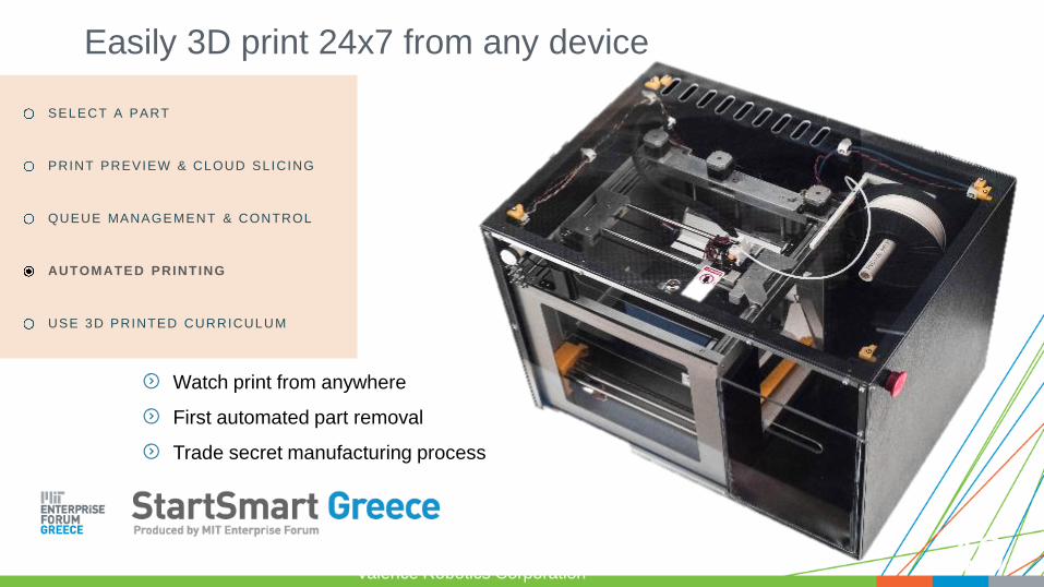
b Watch print from anywhere
b First automated part removal
b Trade secret manufacturing process
Easily 3D print 24x7 from any device

Confidential / Copyright © 2015 New
Valence Robotics Corporation 41
SELECT A PART
PRINT PREVIEW & CLOUD SLICING
QUEUE MANAGEMENT & CONTROL
AUTOMATED PRINTING
USE 3D PRINTED CURRICULUM
Use the 3D object and lesson plan to make STEAM hands on!

Product Specs
Precision flat and level print plate (3µm)
8”x8”x10” build vol.
5,000 mm/s^2 print acceleration
20,000 mm/s^2 max acceleration
6.5 µm X,Y steps
Automated part removal
NVBOTS automated 3D printer
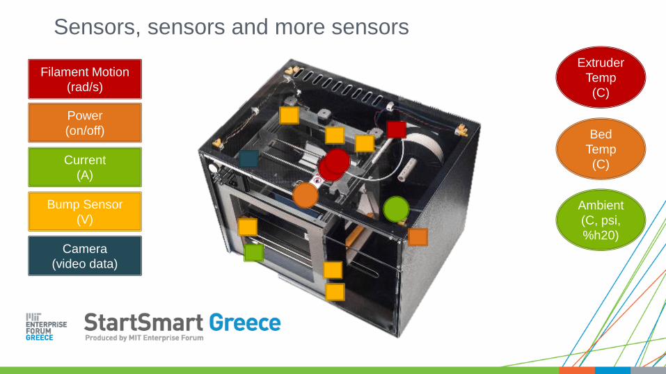
Filament Motion
(rad/s)
Bump Sensor
(V)
Current
(A)
Power
(on/off)
Camera
(video data)
Extruder
Temp
(C)
Bed
Temp
(C)
Ambient
(C, psi,
%h20)
Sensors, sensors and more sensors

Machine state (server signal + power data + camera to confirm)
What is being printed(.stl file)
Status of build volume(camera)
Operating condition impact on process variability(camera + conditions)
What failed, MTTF, MTTR
Data we capture and what we know

Quality vs. Speed
Speed vs. Strength
Two slider inputs determine the part quality, printing time and strength.
Challenging problem because parameter dependencies are non-linear.CAD/CAM
Backend
Calculation
> 100 parameters
Cloud print parameter mapping simplifies CAD/CAM process

1. Determine the effect of modifying the Quality vs. Speed (Q) and
Strength vs. Speed (S) sliders on the dimensional accuracy of a
printed cube.
2. Determine the effect of modifying Q and S on the weight of a
printed cube.
3. Determine how many replicates of data are necessary to provide
significant information concerning the effect of the two sliders.
4. Determine how many replicates are necessary for the NVBOTS
printing process to have consistency of residuals.
DOE, process characterization and optimization for NVBOTS
automated FDM printer using nested ANOVA

Confidential / Copyright © 2015 New
Valence Robotics Corporation 47
On Time
Delivery of
Part in
Spec
Cost
Incoming Raw
Materials Quality
Incoming
GD + T
Cost
CM
M
MFG
Data
Control for
Ambient
Temp
Control for
Pressure
Control
for
Humidity
Cost
Machine
Learning CI
toolpath via
CV
Toolpath
Accuracy
Part
Accuracy
Jam
Warp
+ Positive Feedback
– Negative Feedback
Machine learning applied to NVBOTS 3D printer data system
enables us to build an intelligent manufacturing network

Contact me with any questions:
AJ PerezCEO, NVBOTS
Facebook.com/nvbots
linkedin.com/company/new-valence-robotics-corporation
Twitter.com/nvbots


