POLITECNICO DI TORINO
DIMEAS - Department of Mechanical and Aerospace Engineering
MASTER OF SCIENCE
IN
AUTOMOTIVE ENGINEERING
Master’s Thesis
Design of Emergency Brake System for Formula Student Driverless car
Supervisors Prof. Nicola Amati Prof. Andrea Tonoli
Candidate Mohammed Zubair Ahmed
242545
ACADEMIC YEAR: 2018 - 2019
1
Abstract
The Formula Student competition for Driverless Vehicle (DV) class requires the students
to develop a car that can autonomously make its way around a cone track. To ensure safety
of such a vehicle without a driver, an Emergency Brake System (EBS) is required. The
Emergency Brake System (EBS) shall ensure safe stoppage of the vehicle when any
predefined failure modes get triggered.
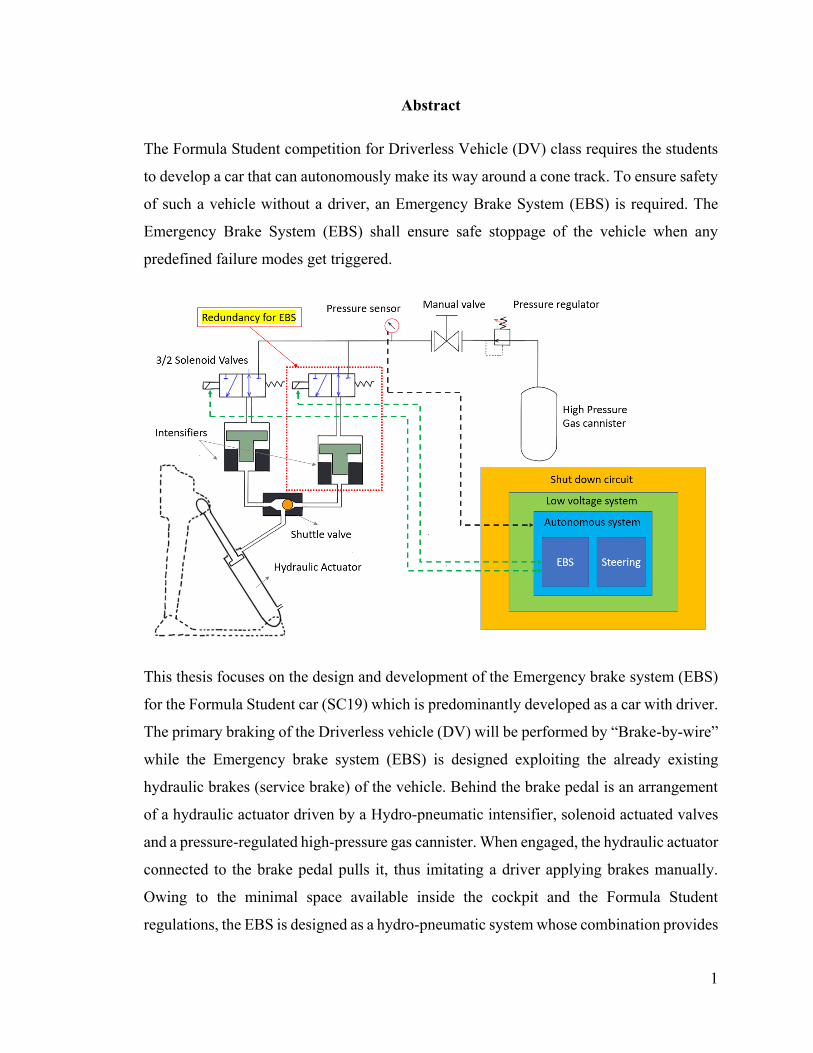
This thesis focuses on the design and development of the Emergency brake system (EBS)
for the Formula Student car (SC19) which is predominantly developed as a car with driver.
The primary braking of the Driverless vehicle (DV) will be performed by “Brake-by-wire”
while the Emergency brake system (EBS) is designed exploiting the already existing
hydraulic brakes (service brake) of the vehicle. Behind the brake pedal is an arrangement
of a hydraulic actuator driven by a Hydro-pneumatic intensifier, solenoid actuated valves
and a pressure-regulated high-pressure gas cannister. When engaged, the hydraulic actuator
connected to the brake pedal pulls it, thus imitating a driver applying brakes manually.
Owing to the minimal space available inside the cockpit and the Formula Student
regulations, the EBS is designed as a hydro-pneumatic system whose combination provides
2
the required pressure output as well as a compact assembly to be mounted inside the
cockpit.
The design specifications of the EBS comes from several design parameters in various
vehicle systems such as Brake pedal gain and travel, Brake overtravel switch actuation,
Brake master cylinders, balance bar, brake calliper and brake pad, brake discs and tires in
addition to vehicle weight, load transfer while braking and the test surface conditions. The
brake pedal along with pedal box base plate is modified to accommodate the actuator and
FEA is performed to ensure the limit of safe stresses. The overall system has been
developed using CATIA™, Stress analysis using Altair Hyperworks and Microsoft Excel
calculator for the brake force calculation. All calculations, design and analyses are
performed complying to Formula Student regulations 2020.
3
Acknowledgement
I am grateful for the opportunity to work on Formula student Driverless project and I feel
obliged to sincerely thank Prof. Nicola Amati and Prof. Andrea Tonoli for their continuous
support and learnings.
I would like to thank Edoardo Corse for his insights regarding the work, a special thanks
to Sarath for his accompany and support in the work.
Grateful for a loving family and friends.
4
Contents
Abstract
Acknowledgements
List of figures ......................................................................................................................6
Abbreviations .....................................................................................................................8
1. Introduction ..................................................................................................................10
2. Braking..........................................................................................................................12
2.1 Braking in ideal conditions .................................................................................12
2.2 Braking in actual conditions ................................................................................17
2.3 Brake architecture of SC19 .................................................................................19
2.4 Hydraulic Brake circuit of SC19 .........................................................................20
3. Emergency Brake System (EBS) for SC19 ................................................................28
Regulations regarding the implementation of EBS according to rulebook FS2020
28
Design concepts for the development of Emergency Brake System EBS ..........36
EBS logic.............................................................................................................38
4. Pedal force calculation .................................................................................................43
4.1 Estimation of Pedal force from deceleration .......................................................43
4.2 Estimation of deceleration from pedal force .......................................................45
4.3 Pedal force for different cases .............................................................................46
4.4 Pedal force results ...............................................................................................48
4.5 Deceleration results .............................................................................................50
5. Calculation for EBS components ................................................................................52
5.1 Calculations for actuator placement ....................................................................52
5
5.1.1 Skeleton study for the estimation of hard points of the Actuator placement ....53
5.1.2 Estimation of the stroke and actuator placement using CAD drawings ............55
5.1.3 Force multiplying factor for the actuator ...........................................................56
5.2 Calculations for Pneumatic actuator ...................................................................57
5.2.1 Pull solution .......................................................................................................57
5.2.2 Push solution .....................................................................................................58
5.3 Calculations for Hydro-pneumatic system ..........................................................59
5.3.1 Pressure and volume flow rate in Hydraulic Actuator ......................................60
5.3.2 Intensifiers (Pressure multipliers) ......................................................................61
5.3.3 High pressure Gas canister (Pressure Accumulator) .........................................63
6. Design of Brake pedal and brake support .................................................................64
6.1 CAD models ........................................................................................................64
6.2 FEM analysis .......................................................................................................65
6.2.1 Push Condition ..................................................................................................65
6.2.2 Pull condition .....................................................................................................69
Conclusion ........................................................................................................................72
Bibliography .....................................................................................................................73
6
List of figures
Figure 1 Squadra Corse car SC19 ......................................................................................11
Figure 2 Forces acting on a vehicle moving on an inclined road. .....................................12
Figure 3 Braking in ideal conditions. .................................................................................15
Figure 4 Ideal Braking - Enlargement of the useful zone with ..........................................16
Figure 5 Conditions for ideal braking ................................................................................18
Figure 6 Braking scheme of SC19 .....................................................................................19
Figure 7 Strain gauge and its placement ............................................................................19
Figure 8 Regenerative braking and Hydraulic braking with pedal force and travel ..........20
Figure 9 hydraulic brake circuit arrangement used for SC19 ............................................20
Figure 10 Forces and moment equilibrium ........................................................................21
Figure 11 Brake rotor or brake disc ...................................................................................22
Figure 12 Master cylinders of the hydraulic brakes ...........................................................23
Figure 13 Brake callipers for the front (4 pistons)-left and rear (2 pistons)-right .............24
Figure 14 balance bar adjustment ......................................................................................26
Figure 15 Pedal gain ..........................................................................................................27
Figure 16 Autonomous system (AS) state machine ...........................................................34
Figure 17 EBS Layout .......................................................................................................37
Figure 18 Pressure flow after inserting High pressure gas cannister .................................39
Figure 19 Pressure flow when EBS is armed.....................................................................40
Figure 20 Pressure flow when the EBS has been triggered. ..............................................40
Figure 21 Pressure flow when releasing pressure after the initial checkup. ......................41
Figure 22 Pressure flow when the EBS has been disabled in order to release the brakes. 42
Figure 23 Results – Pedal force Without regenerative braking .........................................48
Figure 24 Results - Pedal force with regenerative braking ................................................49
Figure 25 Results - Deceleration from pedal force (With spring preload) ........................50
Figure 26 Results - Deceleration from pedal force (Without spring preload) ...................51
Figure 27 Skeleton of Pedal box – hard points for Actuator .............................................53
Figure 28 Pedal travel for BOTS actuation ........................................................................55
7
Figure 29 Actuator stroke for full braking and BOTS actuation .......................................55
Figure 30 Force by the actuator (Amplification factor of the actuator) .............................56
Figure 31 Pneumatic actuator ............................................................................................57
Figure 32 Bore calculation for pneumatic actuator (Pull with spring preload) .................58
Figure 33 Bore calculation for pneumatic actuator (Pull without spring preload) ............58
Figure 34 Pneumatic actuator (Push) .................................................................................58
Figure 35 Pressure in Hydraulic actuator ...........................................................................60
Figure 36 Hydraulic actuator calculation ...........................................................................60
Figure 37 Intensifiers (Pneumatic to hydraulic pressure multiplier) .................................61
Figure 38 Calculations for Intensifier (oil side) .................................................................62
Figure 39 Calculations for Intensifier (Air side)................................................................62
Figure 40 Accumulator (High pressure Gas cannister with Pressure regulator) ...............63
Figure 41 Calculation for Accumulator .............................................................................63
Figure 42 CAD Support bracket ........................................................................................64
Figure 43 CAD Brake pedal ..............................................................................................64
Figure 44 Force application on pedal in XZ plane for push and pull conditions...............65
Figure 45 Force application on pedal in YZ plane for push condition ..............................66
Figure 46 FEM – Displacement Pedal (Push force) ..........................................................67
Figure 47 FEM – Stresses Pedal (Push force) ...................................................................68
Figure 48 FEM – Displacement Base bracket (Push force) ...............................................68
Figure 49 FEM – Stresses Pedal (Push force) ...................................................................69
Figure 50 FEM – Displacement Pedal (Pull force) ............................................................69
Figure 51 FEM – Stresses Pedal (Pull force) .....................................................................70
Figure 52 FEM – Displacement Base support (Pull force) ................................................70
Figure 53 FEM – Stresses Base Support (Pull force) at pedal hinge .................................71
Figure 54 FEM – Stresses Base support (Pull force) at actuator mounting .......................71
8
Abbreviations
ABS - Antilock braking system, 9
ADAS - Advanced driver assistance systems, 9
AIR - Accumulator Isolation Relay, 33
AS - Autonomous System, 35
ASMS - Autonomous System Master Switch, 33
CV - Combustion Vehicle, 32
DV - Driverless Vehicle, 31
EBS - Emergency Brake System, 1
ESP - Electronic stability programme, 9
EV - Electric vehicle, 32
FS - Formula Student, 31
HPC - High Pressure Cannister, 42
LVMS - Low voltage Master Switch, 33
LVS - Low Voltage System, 36
RES - Remote Emergency System, 33
SDC - Shut Down Circuit, 33

9
10
Chapter 1
Introduction
Automobiles plays a very important role in our lives making us capable of moving from
one place to another in order to fulfil the necessities. Over the years, necessities
increased and so did the inventions. It was during the 1800s when Germany and France
invented and perfected the first working models of our today’s automobile. Over the
span of the last 100 years, automobiles saw one of the most rapid advancements.
Number of cars on the road increased and so did the number of accidents. Safety thus
became a matter of highest priority for every car manufacturers and new inventions in
active safety and passive safety systems minimise road accidents and it’s after effects
as they are one of the top causes of death worldwide. Autonomous cars can help to
reduce these problems, as they can achieve better traffic flow and to be more efficient.
This gives a high potential to reduce fuel consumption and emissions caused by traffic
and reduce the risk of accidents among other benefits. Features like ABS, ESP,
automated braking and lane keep assistance are examples of such systems that aim to
assist the driver. These are referred to as Advanced Driver Assistance Systems (ADAS)
and can be seen as stepping-stones in the transition towards Autonomous Driving (AD).
By replacing the driver, a large amount of accidents could be avoided due to the nature
of human behaviour. Formula student has introduced a new class called Formula
student driverless in which students has to build a car which can transition through a
coned track autonomously. Competitions like these help students to have a better
understanding of Autonomous vehicles.
The aim of this thesis is to design the EBS (Emergency brake system) for the Squadra
Corse (SC19) car which was primarily build as a manually driven car as a part of
converting it to a driverless vehicle

11
Figure 1 Squadra Corse car SC19
1.1 Thesis Outline
The thesis is organized as follows.
• Chapter 2: It explains about braking in ideal conditions and how the braking in
real conditions is accomplished, followed by the brake architecture of SC19
which a combination of Hydraulic braking and Regenerative braking and
explanation about the brake components in SC19.
• Chapter 3: It explains about the regulations regarding Emergency Brake system,
followed by design concepts to put such a system in the vehicle, and finally the
logic for EBS design achieved using a Hydro-pneumatic arrangement.
• Chapter 4: It deals with the estimation of the pedal force which must be applied
by the actuator of the EBS, and different cases have been considered for the
force selection and correspondingly the deceleration for all the possible cases.
• Chapter 5: This chapter deals with the calculations regarding the placement of
actuator behind the brake pedal and calculations pertaining to different EBS
solutions.
• Chapter 6: CAD drawings and FEM analysis of Brake pedal and support
12
Chapter 2
This chapter explains about braking in ideal conditions and how the braking in real
conditions is accomplished, followed by the brake architecture of SC19, which is a
combination of Hydraulic braking and Regenerative braking and explanation about the
brake components in SC19.
Braking
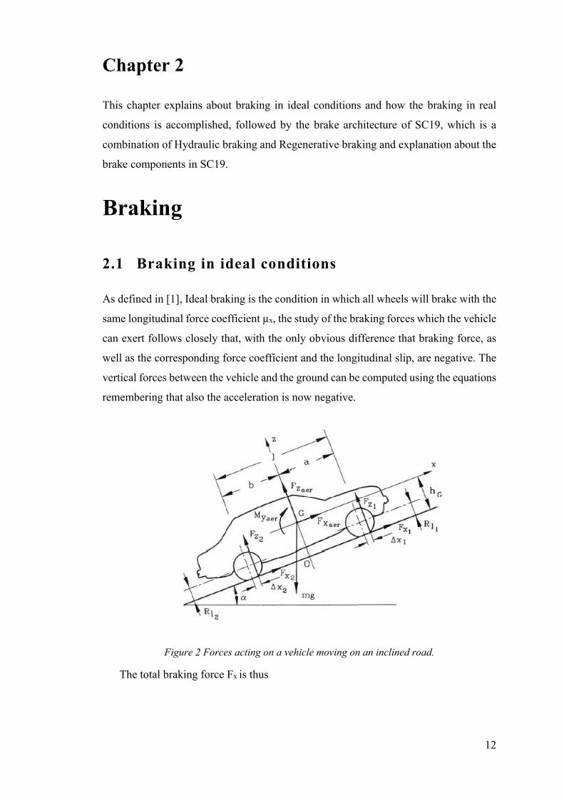
2.1 Braking in ideal conditions
As defined in [1], Ideal braking is the condition in which all wheels will brake with the
same longitudinal force coefficient µx, the study of the braking forces which the vehicle
can exert follows closely that, with the only obvious difference that braking force, as
well as the corresponding force coefficient and the longitudinal slip, are negative. The
vertical forces between the vehicle and the ground can be computed using the equations
remembering that also the acceleration is now negative.
Figure 2 Forces acting on a vehicle moving on an inclined road.
The total braking force Fx is thus

13
where the sum is extended to all the wheels. The longitudinal equation of motion of the
vehicle is then
where m is the actual mass of the vehicle and not the equivalent mass, and a is positive
for uphill grades. The rotating parts of the vehicle are directly slowed down by the
brakes and hence do not enter the evaluation of the forces exchanged between vehicle
and road. They must be accounted for when assessing the required braking power of
the brakes and the energy which must be dissipated.
In a simplified study of braking aerodynamic drag and rolling resistance can be
neglected, since they are usually far smaller than braking forces. Also, rolling resistance
can be considered as causing a braking moment on the wheel more than a braking force
directly on the ground. As in ideal braking all force coefficients fix is assumed to be
equal, the acceleration is,
In case of level road, for a vehicle with no aerodynamic lift, Equation reduces to
The maximum deceleration in ideal conditions can be obtained by introducing the
maximum negative value of µx,
The assumption of ideal braking implies that the braking torques applied on the various
wheels are proportional to the forces Fz, if the radii of the wheels are all equal. As will
be seen later, this can occur in only one condition, unless some sophisticated control
device is implemented to allow braking in ideal conditions.
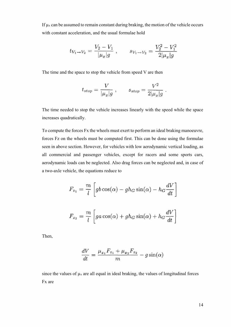
14
If µx can be assumed to remain constant during braking, the motion of the vehicle occurs
with constant acceleration, and the usual formulae hold
The time and the space to stop the vehicle from speed V are then
The time needed to stop the vehicle increases linearly with the speed while the space
increases quadratically.
To compute the forces Fx the wheels must exert to perform an ideal braking manoeuvre,
forces Fz on the wheels must be computed first. This can be done using the formulae
seen in above section. However, for vehicles with low aerodynamic vertical loading, as
all commercial and passenger vehicles, except for racers and some sports cars,
aerodynamic loads can be neglected. Also drag forces can be neglected and, in case of
a two-axle vehicle, the equations reduce to
Then,
since the values of µx are all equal in ideal braking, the values of longitudinal forces
Fx are
15
By eliminating µx using above equations, the following relationship between FXl and
FX2 is readily obtained
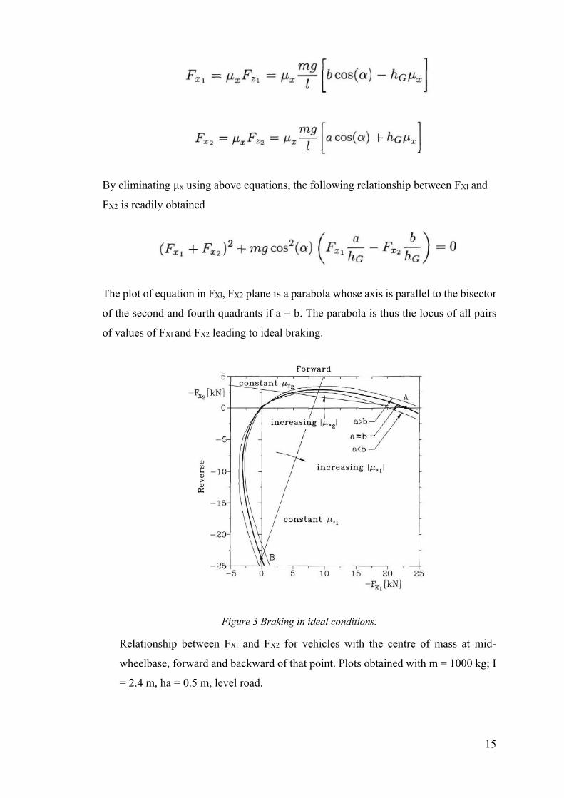
The plot of equation in FXl, FX2 plane is a parabola whose axis is parallel to the bisector
of the second and fourth quadrants if a = b. The parabola is thus the locus of all pairs
of values of FXl and FX2 leading to ideal braking.
Figure 3 Braking in ideal conditions.
Relationship between FXl and FX2 for vehicles with the centre of mass at mid-
wheelbase, forward and backward of that point. Plots obtained with m = 1000 kg; I
= 2.4 m, ha = 0.5 m, level road.
16
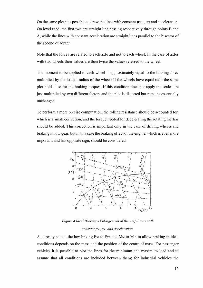
On the same plot it is possible to draw the lines with constant µX1, µX2 and acceleration.
On level road, the first two are straight line passing respectively through points B and
A, while the lines with constant acceleration are straight lines parallel to the bisector of
the second quadrant.
Note that the forces are related to each axle and not to each wheel: In the case of axles
with two wheels their values are then twice the values referred to the wheel.
The moment to be applied to each wheel is approximately equal to the braking force
multiplied by the loaded radius of the wheel: If the wheels have equal radii the same
plot holds also for the braking torques. If this condition does not apply the scales are
just multiplied by two different factors and the plot is distorted but remains essentially
unchanged.
To perform a more precise computation, the rolling resistance should be accounted for,
which is a small correction, and the torque needed for decelerating the rotating inertias
should be added. This correction is important only in the case of driving wheels and
braking in low gear, but in this case the braking effect of the engine, which is even more
important and has opposite sign, should be considered.
Figure 4 Ideal Braking - Enlargement of the useful zone with
constant µX1, µX2 and acceleration.
As already stated, the law linking FXl to FX2, i.e. Mbl to Mb2 to allow braking in ideal
conditions depends on the mass and the position of the centre of mass. For passenger
vehicles it is possible to plot the lines for the minimum and maximum load and to
assume that all conditions are included between them; for industrial vehicles the
17
position of the centre of mass can vary to a larger extent, and a larger set of load
conditions should be considered.
2.2 Braking in actual conditions
The relationship between the braking moments at the rear and front wheels is in practice
different from that stated in order to comply the conditions to obtain ideal braking and
is imposed by the parameters of the actual braking system of the vehicle.
A ratio,
between the braking moments at the front and rear wheels can be defined. If all wheels
have the same radius, its value coincides with the ratio between the braking forces3.
For each value of the deceleration a value of KB which allows the braking to take place
in ideal conditions can be easily found from the plot of Fig. 4.28.
KB depends on the actual layout of the braking system, and in some simple cases is
almost constant. In case of hydraulic braking systems, the braking torque is linked to
the pressure in the hydraulic system by a relationship of the type
where tb, sometimes referred to as efficiency of the brake, is the ratio between the
braking torque and the force exerted on the braking elements and hence has the
dimensions of a length, A is the area of the pistons, p is the pressure and Qm is the
restoring force due to the springs, when they are present.
The value of KB is thus
18
or, if no spring is present as in the case of disc brakes,
In the case of disc brakes eb is almost constant and is, as a first approximation, the
product of the average radius of the brake, the friction coefficient and the number of
braking elements acting on the axle, as braking torques are again referred to the whole
axle. In this case, if the pressure acting on the front and rear wheels is the same, the
value of KB is constant and depends only on geometrical parameters.
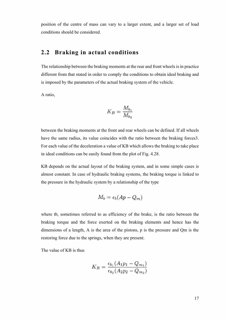
Figure 5 Conditions for ideal braking
Conditions for ideal braking, characteristic line for a system with constant KB and
zones in which the front or the rear wheels lock. In the case shown the value of (µX1)
limit is high enough to cause sliding beyond point A.
19
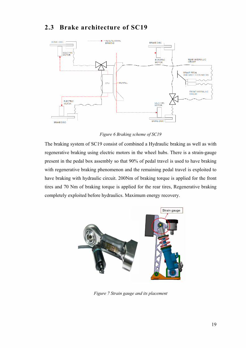
2.3 Brake architecture of SC19
Figure 6 Braking scheme of SC19
The braking system of SC19 consist of combined a Hydraulic braking as well as with
regenerative braking using electric motors in the wheel hubs. There is a strain-gauge
present in the pedal box assembly so that 90% of pedal travel is used to have braking
with regenerative braking phenomenon and the remaining pedal travel is exploited to
have braking with hydraulic circuit. 200Nm of braking torque is applied for the front
tires and 70 Nm of braking torque is applied for the rear tires, Regenerative braking
completely exploited before hydraulics. Maximum energy recovery.
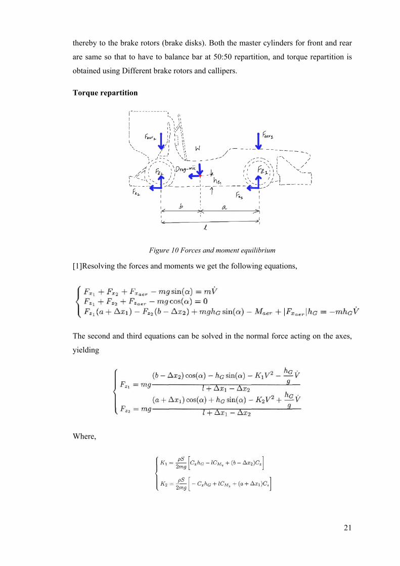
Figure 7 Strain gauge and its placement

20
Figure 8 Regenerative braking and Hydraulic braking with pedal force and travel
In the figure shown above
Region 1 - Only regenerative braking, pedal doesn’t move due to preload.
Region 2 - Pedal start moving but no hydraulic contribution. Still only
regenerative.
Region 3 - After regenerative 100%, Hydraulic braking
2.4 Hydraulic Brake circuit of SC19
Figure 9 hydraulic brake circuit arrangement used for SC19
Consists of brake pedal box containing brake pedal, master cylinders, fluid reservoirs,
a balance bar, thereby connecting to the hydraulic lines to the brake callipers and
21
thereby to the brake rotors (brake disks). Both the master cylinders for front and rear
are same so that to have to balance bar at 50:50 repartition, and torque repartition is
obtained using Different brake rotors and callipers.
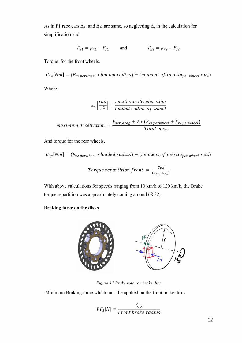
Torque repartition
Figure 10 Forces and moment equilibrium
[1]Resolving the forces and moments we get the following equations,
The second and third equations can be solved in the normal force acting on the axes,
yielding
Where,
22
As in F1 race cars Δx1 and Δx2 are same, so neglecting Δ, in the calculation for
simplification and
𝐹𝑥1 = 𝜇𝑥1 ∗ 𝐹𝑧1 and 𝐹𝑥2 = 𝜇𝑥2 ∗ 𝐹𝑧2
Torque for the front wheels,
𝐶𝐹𝐴[𝑁𝑚] = (𝐹𝑥1 𝑝𝑒𝑟𝑤ℎ𝑒𝑒𝑙 ∗ 𝑙𝑜𝑎𝑑𝑒𝑑 𝑟𝑎𝑑𝑖𝑢𝑠) + (𝑚𝑜𝑚𝑒𝑛𝑡 𝑜𝑓 𝑖𝑛𝑒𝑟𝑡𝑖𝑎𝑝𝑒𝑟 𝑤ℎ𝑒𝑒𝑙 ∗ 𝛼𝐴)
Where,
𝛼𝐴 [𝑟𝑎𝑑
𝑠2] =
𝑚𝑎𝑥𝑖𝑚𝑢𝑚 𝑑𝑒𝑐𝑒𝑙𝑒𝑟𝑎𝑡𝑖𝑜𝑛
𝑙𝑜𝑎𝑑𝑒𝑑 𝑟𝑎𝑑𝑖𝑢𝑠 𝑜𝑓 𝑤ℎ𝑒𝑒𝑙
𝑚𝑎𝑥𝑖𝑚𝑢𝑚 𝑑𝑒𝑐𝑒𝑙𝑟𝑎𝑡𝑖𝑜𝑛 = 𝐹𝑎𝑒𝑟_𝑑𝑟𝑎𝑔 + 2 ∗ (𝐹𝑥1 𝑝𝑒𝑟𝑤ℎ𝑒𝑒𝑙 + 𝐹𝑥2 𝑝𝑒𝑟𝑤ℎ𝑒𝑒𝑙)
𝑇𝑜𝑡𝑎𝑙 𝑚𝑎𝑠𝑠
And torque for the rear wheels,
𝐶𝐹𝑝[𝑁𝑚] = (𝐹𝑥2 𝑝𝑒𝑟𝑤ℎ𝑒𝑒𝑙 ∗ 𝑙𝑜𝑎𝑑𝑒𝑑 𝑟𝑎𝑑𝑖𝑢𝑠) + (𝑚𝑜𝑚𝑒𝑛𝑡 𝑜𝑓 𝑖𝑛𝑒𝑟𝑡𝑖𝑎𝑝𝑒𝑟 𝑤ℎ𝑒𝑒𝑙 ∗ 𝛼𝑃)
𝑇𝑜𝑟𝑞𝑢𝑒 𝑟𝑒𝑝𝑎𝑟𝑡𝑖𝑡𝑖𝑜𝑛 𝑓𝑟𝑜𝑛𝑡 = (𝐶𝐹𝐴)
(𝐶𝐹𝐴+𝐶𝐹𝑝)
With above calculations for speeds ranging from 10 km/h to 120 km/h, the Brake
torque repartition was approximately coming around 68:32,
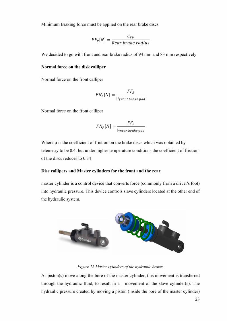
Braking force on the disks
Figure 11 Brake rotor or brake disc
Minimum Braking force which must be applied on the front brake discs
𝐹𝐹𝐴[𝑁] =𝐶𝐹𝐴
𝐹𝑟𝑜𝑛𝑡 𝑏𝑟𝑎𝑘𝑒 𝑟𝑎𝑑𝑖𝑢𝑠
23
Minimum Braking force must be applied on the rear brake discs
𝐹𝐹𝑃[𝑁] =𝐶𝐹𝑃
𝑅𝑒𝑎𝑟 𝑏𝑟𝑎𝑘𝑒 𝑟𝑎𝑑𝑖𝑢𝑠
We decided to go with front and rear brake radius of 94 mm and 83 mm respectively
Normal force on the disk calliper
Normal force on the front calliper
𝐹𝑁𝐴[𝑁] =𝐹𝐹𝐴
µ𝑓𝑟𝑜𝑛𝑡 𝑏𝑟𝑎𝑘𝑒 𝑝𝑎𝑑
Normal force on the front calliper
𝐹𝑁𝑃[𝑁] =𝐹𝐹𝑃
µ𝑅𝑒𝑎𝑟 𝑏𝑟𝑎𝑘𝑒 𝑝𝑎𝑑
Where µ is the coefficient of friction on the brake discs which was obtained by
telemetry to be 0.4, but under higher temperature conditions the coefficient of friction
of the discs reduces to 0.34
Disc callipers and Master cylinders for the front and the rear
master cylinder is a control device that converts force (commonly from a driver's foot)
into hydraulic pressure. This device controls slave cylinders located at the other end of
the hydraulic system.
Figure 12 Master cylinders of the hydraulic brakes
As piston(s) move along the bore of the master cylinder, this movement is transferred
through the hydraulic fluid, to result in a movement of the slave cylinder(s). The
hydraulic pressure created by moving a piston (inside the bore of the master cylinder)
24
toward the slave cylinder(s) compresses the fluid evenly, but by varying the
comparative surface area of the master cylinder and each slave cylinder, one can vary
the amount of force and displacement applied to each slave cylinder, relative to the
amount of force and displacement applied to the master cylinder.
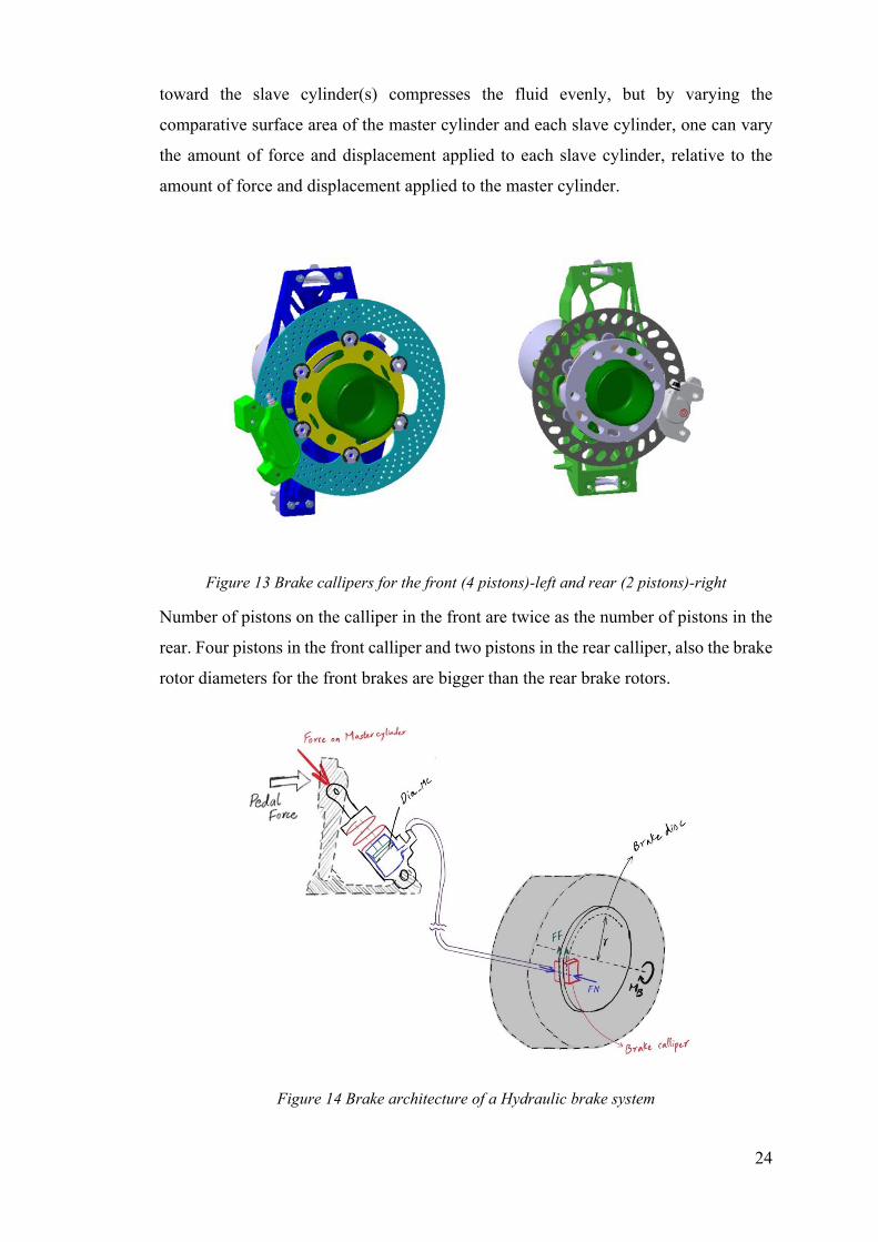
Figure 13 Brake callipers for the front (4 pistons)-left and rear (2 pistons)-right
Number of pistons on the calliper in the front are twice as the number of pistons in the
rear. Four pistons in the front calliper and two pistons in the rear calliper, also the brake
rotor diameters for the front brakes are bigger than the rear brake rotors.
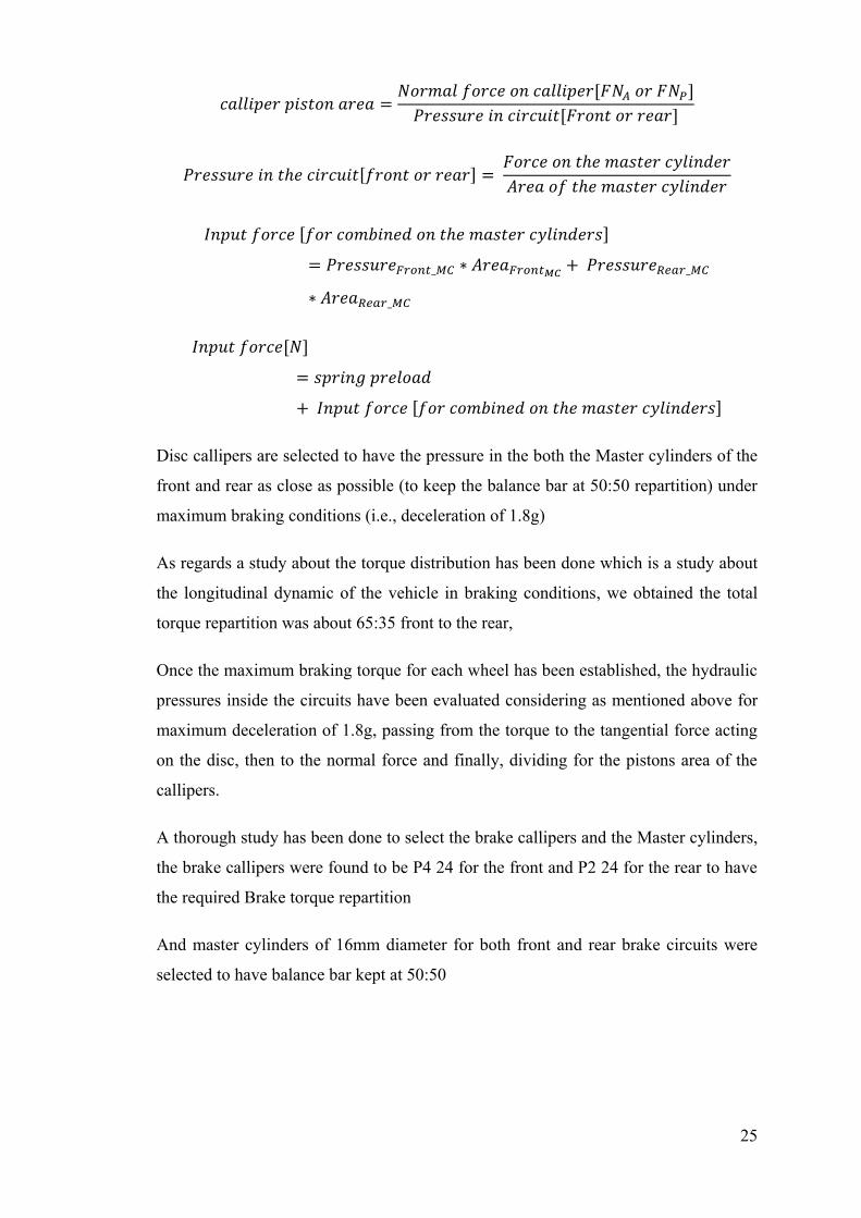
Figure 14 Brake architecture of a Hydraulic brake system
25
𝑐𝑎𝑙𝑙𝑖𝑝𝑒𝑟 𝑝𝑖𝑠𝑡𝑜𝑛 𝑎𝑟𝑒𝑎 =𝑁𝑜𝑟𝑚𝑎𝑙 𝑓𝑜𝑟𝑐𝑒 𝑜𝑛 𝑐𝑎𝑙𝑙𝑖𝑝𝑒𝑟[𝐹𝑁𝐴 𝑜𝑟 𝐹𝑁𝑃]
𝑃𝑟𝑒𝑠𝑠𝑢𝑟𝑒 𝑖𝑛 𝑐𝑖𝑟𝑐𝑢𝑖𝑡[𝐹𝑟𝑜𝑛𝑡 𝑜𝑟 𝑟𝑒𝑎𝑟]
𝑃𝑟𝑒𝑠𝑠𝑢𝑟𝑒 𝑖𝑛 𝑡ℎ𝑒 𝑐𝑖𝑟𝑐𝑢𝑖𝑡[𝑓𝑟𝑜𝑛𝑡 𝑜𝑟 𝑟𝑒𝑎𝑟] = 𝐹𝑜𝑟𝑐𝑒 𝑜𝑛 𝑡ℎ𝑒 𝑚𝑎𝑠𝑡𝑒𝑟 𝑐𝑦𝑙𝑖𝑛𝑑𝑒𝑟
𝐴𝑟𝑒𝑎 𝑜𝑓 𝑡ℎ𝑒 𝑚𝑎𝑠𝑡𝑒𝑟 𝑐𝑦𝑙𝑖𝑛𝑑𝑒𝑟
𝐼𝑛𝑝𝑢𝑡 𝑓𝑜𝑟𝑐𝑒 [𝑓𝑜𝑟 𝑐𝑜𝑚𝑏𝑖𝑛𝑒𝑑 𝑜𝑛 𝑡ℎ𝑒 𝑚𝑎𝑠𝑡𝑒𝑟 𝑐𝑦𝑙𝑖𝑛𝑑𝑒𝑟𝑠]
= 𝑃𝑟𝑒𝑠𝑠𝑢𝑟𝑒𝐹𝑟𝑜𝑛𝑡_𝑀𝐶 ∗ 𝐴𝑟𝑒𝑎𝐹𝑟𝑜𝑛𝑡𝑀𝐶+ 𝑃𝑟𝑒𝑠𝑠𝑢𝑟𝑒𝑅𝑒𝑎𝑟_𝑀𝐶
∗ 𝐴𝑟𝑒𝑎𝑅𝑒𝑎𝑟_𝑀𝐶
𝐼𝑛𝑝𝑢𝑡 𝑓𝑜𝑟𝑐𝑒[𝑁]
= 𝑠𝑝𝑟𝑖𝑛𝑔 𝑝𝑟𝑒𝑙𝑜𝑎𝑑
+ 𝐼𝑛𝑝𝑢𝑡 𝑓𝑜𝑟𝑐𝑒 [𝑓𝑜𝑟 𝑐𝑜𝑚𝑏𝑖𝑛𝑒𝑑 𝑜𝑛 𝑡ℎ𝑒 𝑚𝑎𝑠𝑡𝑒𝑟 𝑐𝑦𝑙𝑖𝑛𝑑𝑒𝑟𝑠]
Disc callipers are selected to have the pressure in the both the Master cylinders of the
front and rear as close as possible (to keep the balance bar at 50:50 repartition) under
maximum braking conditions (i.e., deceleration of 1.8g)
As regards a study about the torque distribution has been done which is a study about
the longitudinal dynamic of the vehicle in braking conditions, we obtained the total
torque repartition was about 65:35 front to the rear,
Once the maximum braking torque for each wheel has been established, the hydraulic
pressures inside the circuits have been evaluated considering as mentioned above for
maximum deceleration of 1.8g, passing from the torque to the tangential force acting
on the disc, then to the normal force and finally, dividing for the pistons area of the
callipers.
A thorough study has been done to select the brake callipers and the Master cylinders,
the brake callipers were found to be P4 24 for the front and P2 24 for the rear to have
the required Brake torque repartition
And master cylinders of 16mm diameter for both front and rear brake circuits were
selected to have balance bar kept at 50:50
26
Balance bar
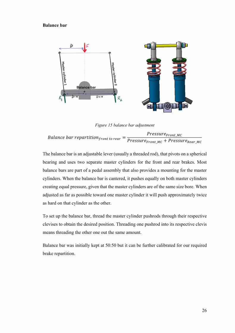
Figure 15 balance bar adjustment
𝐵𝑎𝑙𝑎𝑛𝑐𝑒 𝑏𝑎𝑟 𝑟𝑒𝑝𝑎𝑟𝑡𝑖𝑡𝑖𝑜𝑛𝑓𝑟𝑜𝑛𝑡 𝑡𝑜 𝑟𝑒𝑎𝑟 =𝑃𝑟𝑒𝑠𝑠𝑢𝑟𝑒𝐹𝑟𝑜𝑛𝑡_𝑀𝐶
𝑃𝑟𝑒𝑠𝑠𝑢𝑟𝑒𝐹𝑟𝑜𝑛𝑡_𝑀𝐶 + 𝑃𝑟𝑒𝑠𝑠𝑢𝑟𝑒𝑅𝑒𝑎𝑟_𝑀𝐶
The balance bar is an adjustable lever (usually a threaded rod), that pivots on a spherical
bearing and uses two separate master cylinders for the front and rear brakes. Most
balance bars are part of a pedal assembly that also provides a mounting for the master
cylinders. When the balance bar is cantered, it pushes equally on both master cylinders
creating equal pressure, given that the master cylinders are of the same size bore. When
adjusted as far as possible toward one master cylinder it will push approximately twice
as hard on that cylinder as the other.
To set up the balance bar, thread the master cylinder pushrods through their respective
clevises to obtain the desired position. Threading one pushrod into its respective clevis
means threading the other one out the same amount.
Balance bar was initially kept at 50:50 but it can be further calibrated for our required
brake repartition.
27
Brake pedal gain
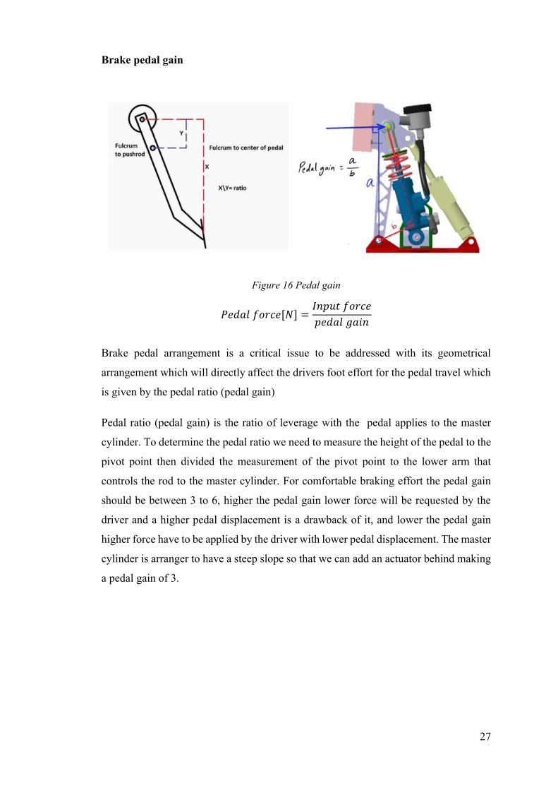
Figure 16 Pedal gain
𝑃𝑒𝑑𝑎𝑙 𝑓𝑜𝑟𝑐𝑒[𝑁] =𝐼𝑛𝑝𝑢𝑡 𝑓𝑜𝑟𝑐𝑒
𝑝𝑒𝑑𝑎𝑙 𝑔𝑎𝑖𝑛
Brake pedal arrangement is a critical issue to be addressed with its geometrical
arrangement which will directly affect the drivers foot effort for the pedal travel which
is given by the pedal ratio (pedal gain)
Pedal ratio (pedal gain) is the ratio of leverage with the pedal applies to the master
cylinder. To determine the pedal ratio we need to measure the height of the pedal to the
pivot point then divided the measurement of the pivot point to the lower arm that
controls the rod to the master cylinder. For comfortable braking effort the pedal gain
should be between 3 to 6, higher the pedal gain lower force will be requested by the
driver and a higher pedal displacement is a drawback of it, and lower the pedal gain
higher force have to be applied by the driver with lower pedal displacement. The master
cylinder is arranger to have a steep slope so that we can add an actuator behind making
a pedal gain of 3.
28
Chapter 3
This chapter explains about the regulations regarding Emergency Brake system,
followed by design concepts to put such a system in the vehicle, and finally the logic
for EBS design achieved using a Hydro-pneumatic arrangement.
Emergency Brake System (EBS) for SC19
Regulations regarding the implementation of
EBS according to rulebook FS2020
Brake system (T6) [2]
T6.1 Brake System - General
T6.1.1 The vehicle must be equipped with a hydraulic brake system that acts on all four
wheels and is operated by a single control.
T6.1.2 The brake system must have two independent hydraulic circuits such that in the
case of a leak or failure at any point in the system, effective braking power is maintained
on at least two wheels. Each hydraulic circuit must have its own fluid reserve, either by
the use of separate reservoirs or by the use of a dammed reservoir.
T6.1.3 A single brake acting on a limited-slip differential is acceptable.
T6.1.4 “Brake-by-wire” systems are prohibited. [DV ONLY] In autonomous mode, it
is allowed to use “brake-by-wire”. In manual mode, T6.1.1 applies.
T6.1.5 Unarmoured plastic brake lines are prohibited.
T6.1.6 The brake system must be protected from failure of the drivetrain, see T7.3.2,
from touching any movable part and from minor collisions.
T6.1.7 In side view any portion of the brake system that is mounted on the sprung part
of the vehicle must not below the lower surface of the chassis.
29
T6.1.8 The brake pedal and its mounting must be designed to withstand a force of 2 kN
without any failure of the brake system or pedal box. This may be tested by pressing
the pedal with the maximum force that can be exerted by any official when seated
normally.
T6.1.9 The brake pedal must be fabricated from steel or aluminium or machined from
steel, aluminium or titanium.
T6.1.10 [EV ONLY] The first 90% of the brake pedal travel may be used to regenerate
brake energy without actuating the hydraulic brake system. The remaining brake pedal
travel must directly actuate the hydraulic brake system, but brake energy regeneration
may remain active.
Brake Over-Travel Switch (BOTS) (T6.2) [2]
T6.2.1 A brake pedal over-travel switch must be installed on the vehicle as part of the
shutdown circuit, as in EV6 or CV4.1. This switch must be installed so that in the event
of a failure in at least one of the brakes circuits the brake pedal over-travel will result
in the shutdown circuit being opened. This must function for all possible brake pedal
and brake balance settings without damaging any part of the vehicle.
T6.2.2 Repeated actuation of the switch must not close the shutdown circuit, and it must
be designed so that the driver cannot reset it.
T6.2.3 The brake over travel-switch must be a mechanical single pole, single throw
switch, commonly known as a two-position switch, push-pull or flip type, it may consist
of a series connection of switches.
Emergency Brake System (EBS) (DV3) [2]
DV3.1 Technical Requirements
DV3.1.1 All specifications of the brake system from T6 remain valid.
DV3.1.2 The vehicle must be equipped with an EBS, that must be supplied by LVMS,
ASMS, RES and a relay which is supplied by the SDC ([EV ONLY] parallel to the
AIR, but must not be delayed/[CV ONLY] parallel to fuel pump relay).
30
DV3.1.3 The EBS must only use passive systems with mechanical energy storage.
Electrical power loss at EBS must lead to a direct emergency brake manoeuvre (keep
in mind T11.3.1!).
DV3.1.4 The EBS may be part of the hydraulic brake system. For all components of
pneumatic and hydraulic EBS actuation not covered by T6, T9 is applied.
DV3.1.5 When the EBS is part of the hydraulic brake system, the manual brake
actuation (by brake pedal) may be deactivated for autonomous driving.
DV3.1.6 The EBS must be designed so that any official can easily deactivate it. All
deactivation points must be in proximity to each other, easily accessible without the
need for tools/removing any body parts/excessively bending into the cockpit. They
must be able to be operated also when wearing gloves.
DV3.1.7 A pictographic description of the location of the EBS release points must be
clearly visible in proximity to the ASMS. The necessary steps to release the EBS must
be clearly marked (e.g. pictographic or with pull/push/turn arrow) at each release point.
This point must be marked by a red arrow of 100mm length (shaft width of 20mm) with
“EBS release” in white letters on it.
DV3.1.8 The use of push-in fittings is prohibited in function critical pneumatic circuits
of the EBS and any other system which uses the same energy storage without proper
decoupling.
Functional Safety (DV3.2) [2]
DV3.2.1 Due to the safety critical character of the EBS, the system must either remain
fully functional, or the vehicle must automatically transition to the safe state in case of
a single failure mode.
DV3.2.2 The safe state is the vehicle at a standstill, brakes engaged to prevent the
vehicle from rolling, and an open SDC.
DV3.2.3 To get to the safe state, the vehicle must perform an autonomous brake
manoeuvre described in section DV3.3 and IN6.3.
DV3.2.4 An initial check must be performed to ensure that EBS and its redundancy is
able to build up brake pressure as expected, before AS transitions to “AS Ready”.
31
DV3.2.5 The tractive system is not considered to be a brake system.
DV3.2.6 The service brake system may be used as redundancy if two-way monitoring
is ensured.
DV3.2.7 A red indicator light in the cockpit that is easily visible even in bright sunlight
and clearly marked with the lettering “EBS” must light up if the EBS detects a failure.
EBS Performance (DV3.3) [2]
DV3.3.1 The system reaction time (the time between entering the triggered state and
the start of the deceleration) must not exceed 200 ms.
DV3.3.2 The average deceleration must be greater than 8 m/s2 under dry track
conditions.
DV3.3.3 Whilst decelerating, the vehicle must remain in a stable driving condition (i.e.
no unintended yaw movement). This can be either a controlled deceleration (steering
and braking control is active) or a stable braking in a straight line with all four wheels
locked.
DV3.3.4 The performance of the system will be tested at technical inspection, see
IN6.3.
Driverless Inspection EBS Test (IN6.3) [2]
IN6.3.1 The EBS performance will be tested dynamically and must demonstrate the
performance described in DV3.3.
IN6.3.2 The test will be performed in a straight line marked with cones similar to
acceleration.
IN6.3.3 During the brake test, the vehicle must accelerate in autonomous mode up to at
least 40 km=h within 20m. From the point where the RES is triggered, the vehicle must
come to a safe stop within a maximum distance of 10 m.
IN6.3.4 In case of wet track conditions, the stopping distance will be scaled by the
officials dependent on the friction level of the track.
Autonomous System Master Switch (ASMS) (DV2.2) [2]
32
DV2.2.1 Each DV must be equipped with an ASMS, according to T11.2.
DV2.2.2 The ASMS must be mounted in the middle of a completely blue circular area
of 50mm diameter placed on a high contrast background.
DV2.2.3 The ASMS must be marked with “AS”.
DV2.2.4 The power supply of the steering and braking actuators must be switched by
LVMS and ASMS
DV2.2.5 When the ASMS is in “Off” position, the following must be fulfilled:
• No steering, braking and propulsion actuation can be performed by request of the autonomous system.
• The sensors and the processing units can stay operational.
• The vehicle must be able to be pushed as specified in A6.7.
• It must be possible to operate the vehicle manually as a normal CV or EV.
DV2.2.6 It is strictly forbidden to switch the ASMS to the “On” position if a person is
inside the vehicle.
DV2.2.7 After switching the ASMS to the “On” position, the vehicle may not start
moving and the brakes must remain closed (“AS ready” state, Figure 21) until a “Go”
signal is sent via the RES (“AS driving” state, Figure 21).
DV2.2.8 The ASMS must be fitted with a “lockout/tagout” capability to prevent
accidental activation of the AS. The ASR must ensure that the ASMS is locked in the
off position whenever the vehicle is outside the dynamic area or driven in manual mode.
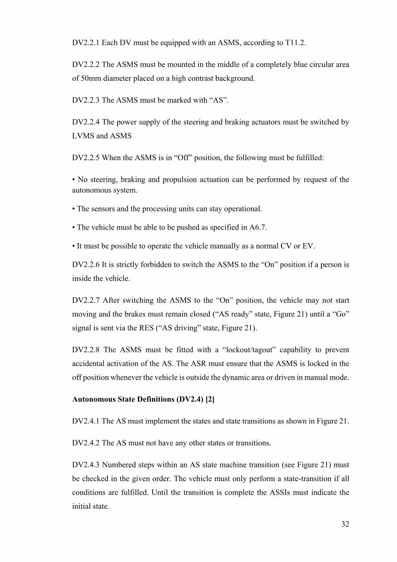
Autonomous State Definitions (DV2.4) [2]
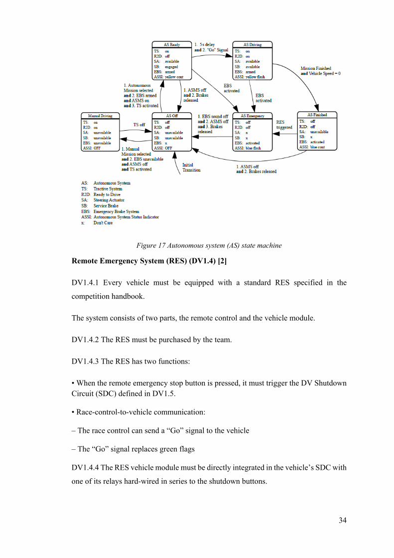
DV2.4.1 The AS must implement the states and state transitions as shown in Figure 21.
DV2.4.2 The AS must not have any other states or transitions.
DV2.4.3 Numbered steps within an AS state machine transition (see Figure 21) must
be checked in the given order. The vehicle must only perform a state-transition if all
conditions are fulfilled. Until the transition is complete the ASSIs must indicate the
initial state.
33
DV2.4.4 The steering actuator can only have the following states:
• “unavailable”: power supply of the actuator is disconnected, manual steering is possible
• “available”: power supply is connected, and the actuator can respond to commands of the AS according to DV2.3.1.
DV2.4.5 The service brake can only have the following states:
• “unavailable”: power supply of the actuator is disconnected, manual braking is
possible
• “engaged”: prevents the vehicle from rolling on a slope up to 15%
• “available”: responds immediately to commands from the AS For the state transition of the service brake actuator no manual steps (e.g. operating manual valves / (dis-)connecting mechanical elements) are allowed.
DV2.4.6 The EBS can only have the following states:
• “unavailable”: the actuator is disconnected from the system/the energy storage is de-
energized, emergency brake manoeuvre is not possible.
• “armed”: will initiate an emergency brake manoeuvre immediately if the SDC is
opened or the LVS supply is interrupted
• “activated”: brakes are closed and power to EBS is cut. Brakes may only be released
after performing manual steps.
34
Figure 17 Autonomous system (AS) state machine
Remote Emergency System (RES) (DV1.4) [2]
DV1.4.1 Every vehicle must be equipped with a standard RES specified in the
competition handbook.
The system consists of two parts, the remote control and the vehicle module.
DV1.4.2 The RES must be purchased by the team.
DV1.4.3 The RES has two functions:
• When the remote emergency stop button is pressed, it must trigger the DV Shutdown Circuit (SDC) defined in DV1.5.
• Race-control-to-vehicle communication:
– The race control can send a “Go” signal to the vehicle
– The “Go” signal replaces green flags
DV1.4.4 The RES vehicle module must be directly integrated in the vehicle’s SDC with
one of its relays hard-wired in series to the shutdown buttons.
35
DV1.4.5 The antenna of the RES must be mounted unobstructed and without interfering
parts in proximity (other antennas, etc.).
Shutdown circuit (DV1.5) [2]
DV1.5.1 The drivetrain-specific requirements for the SDC (see CV4.1 or EV6) remain
valid for DV.
DV1.5.2 If the SDC is opened by the Autonomous System (AS) or the RES, it has to
be latched open by a non-programmable logic that can only be reset manually (either a
button outside of the vehicle, in proximity to the ASMS, or via LVMS power cycle).
DV1.5.3 The SDC may only be closed by the AS, if the following conditions are
fulfilled:
• Manual Driving: Manual Mission is selected; the AS has checked that EBS is unavailable (No EBS actuation possible).
• Autonomous Driving: Autonomous Mission is selected, ASMS is switched on and enough brake pressure is built up (brakes are closed).
Compressed gas systems and high-pressure hydraulics (T 9) [2]
T9.1 Compressed Gas Cylinders and Lines
T9.1.1 Any system on the vehicle that uses a compressed gas as an actuating medium
must comply with the following requirements:
• The working gas must be non-flammable.
• The gas cylinder/tank must be of proprietary manufacture, designed and built for the pressure being used, certified and labelled or stamped appropriately.
• A pressure regulator must be used and mounted directly onto the gas cylinder/tank.
• The gas cylinder/tank and lines must be protected from rollover, collision from any direction, or damage resulting from the failure of rotating equipment.
• The gas cylinder/tank and the pressure regulator must be located within the rollover protection envelope T1.1.14, but must not be located in the cockpit.
• The gas cylinder/tank must be securely mounted to the chassis, engine or transmission.
• The axis of the gas cylinder/tank must not point at the driver.
36
• The gas cylinder/tank must be insulated from any heat sources.
• The gas lines and fittings must be appropriate for the maximum possible operating pressure of the system.
T9.2 High Pressure Hydraulic Pumps and Lines
T9.2.1 The driver and anyone standing outside the vehicle must be shielded from any
hydraulic pumps and lines with line pressures of 2100 kPa or higher. The shields must
be steel or aluminium with a minimum thickness of 1mm. Brake lines are not
considered as high-pressure hydraulic lines.
Design concepts for the development of
Emergency Brake System EBS
Since the Emergency brake system must be actuated only once if there is a power loss
to the Low voltage system of the vehicle or if the race marshal triggers the stoppage
actuation using a remote (RES – Remote Emergency System). Therefore, exploiting the
already existing service brake for the emergency brake action is a good idea.
Brake actuation using an electrically driven servo motor with a cable drive
This kind of arrangement was not realised given to the fact that cables have to be pre-
tensioned and one big reason for not using any electric actuator is due to the fact that
EBS has to automatically engage when there is a loss of power to the Autonomous
system or Low voltage system of the vehicle and the motors are electrically driven so
decided to have an actuator behind the brake pedal hinged to the base and other end
attached to the brake pedal top, so that it can pull and swivel at the same time, which
could be either a Hydraulic or pneumatic.
Brake actuation using an Electric linear actuator
Given to the FS rules the EBS must engage when there is electrical power loss, so all
electric actuators have been avoided. And, electric actuators are comparatively slow
with respect to hydraulic or pneumatic actuators, electric actuators do not fulfil the FS
regulations to have the brake actuation within 200 milli seconds.
37
Brake actuation using a Pneumatic Actuator
A preliminary design was done to have a pneumatic actuator with a cannister and
pressure regulator, all commercially available pneumatic actuators works at a
maximum input pressure of 10 bar and some special pneumatic actuators works at input
pressure of 17 bar, in both the cases the pneumatic actuator bore size was very high for
our required power rating, bore sizes of minimum 60 mm was coming out of
calculations.
Brake actuation using a hydraulic actuator
Hydraulic actuators can be used under higher operating pressures, hence hydraulic
actuators can provide higher forces with bore of smaller size. In our design arrangement
we need a hydraulic actuator capable of providing the required force at minimum
actuation rate of 200 milli seconds.
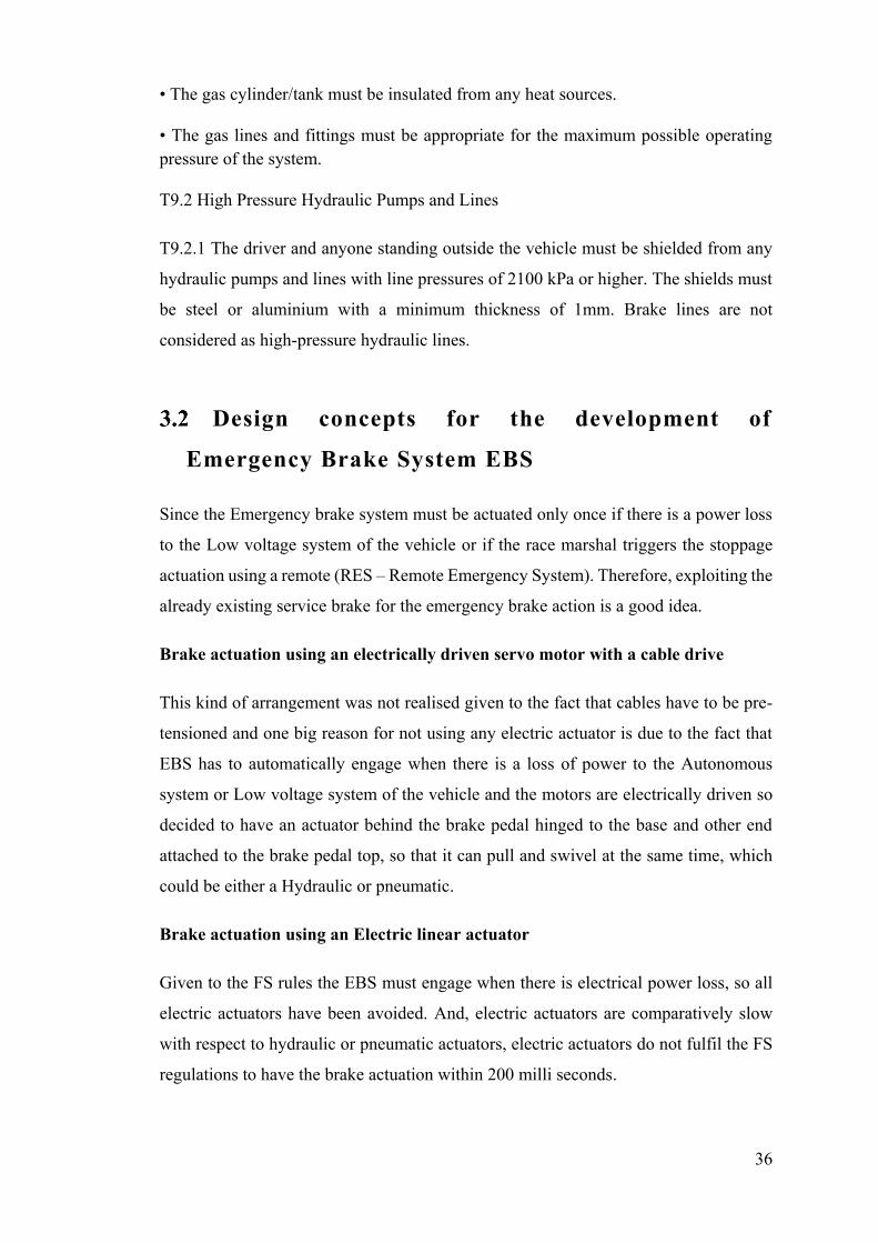
Figure 18 EBS Layout
Since we do not have a pump to provide the hydraulic pressure, it was decided to go
with the use of a high-pressure gas cannister with Intensifiers (The Hydro-Pneumatic
intensifier consists of a double acting Pneumatic Cylinder and a Hydraulic high-
pressure chamber. The Pneumatic Cylinder piston rod is forced into the hydraulic
chamber resulting in high-pressure oil displacement). Intensifiers can be actuated using
solenoid actuated valves (two position three-way valves). Since the brake pedal has to
be actuated only as it is an Emergency brake actuation which will bring the vehicle to
a complete stoppage.
38
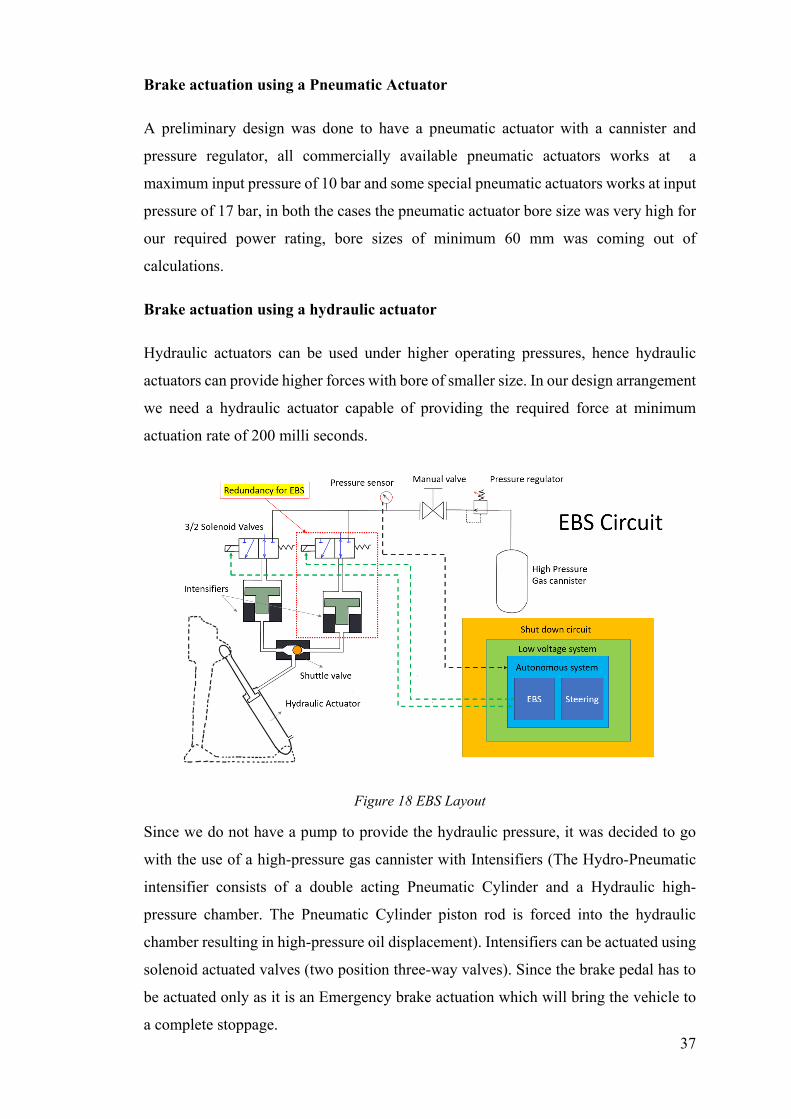
EBS logic
Formula Student Driverless cars are equipped with an Emergency Brake System (EBS).
This is actuated via the Remote Emergency System (RES) or during any loss of voltage
to the LVS (Low Voltage System) and at the end of completion of Autonomous driving
(AS finished).
In order to guarantee the safety of the autonomous vehicles in the operation and
handling for all parties concerned, the team must fulfil some special requirements. Each
vehicle must be equipped with a so-called RES (Remote Emergency System), which
fulfils two functions. By means of this remote control, the required Emergency Brake
System (EBS) can be triggered and the vehicle can be stopped in emergency situations.
At the same time, the RES control system enables the “Go” signal to be sent to the
vehicle at the start of the dynamic disciplines. Furthermore, all FSD vehicles are
equipped with different coloured signal lamps, which indicate the respective operating
states of the vehicle. In autonomous mode, a yellow signal is illuminated, whilst a blue
light indicates the status of the RES. These systems must be tested during the Driverless
Inspection.
Due to rule DV3.1.3 of FS2020 a passive system with mechanically stored energy must
be used for the EBS. This led to the Hydro-pneumatic system for the brake solution.
39
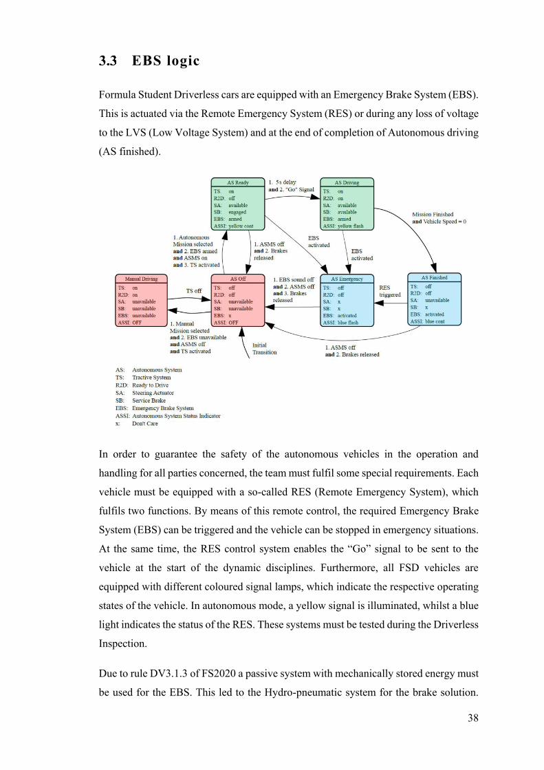
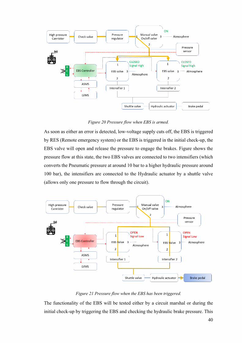
The EBS has been designed to maintain the states illustrated in figures below, The HPC
(High pressure gas cannister) will be inserted when the vehicle is turned off, and hence
the electric normally opened EBS valve still open. Consequently, the manual on/off
valve needs to be closed during insertion of the Cannister, as seen in Figure. The yellow
line describes the pressure flow in the system, pressure regulator is used to manipulate
the high pressure from the cannister to the operating pressure of the EBS valves
Figure 19 Pressure flow after inserting High pressure gas cannister
When the vehicle has been started and no errors have been detected, the EBS valve is
supplied by the low-voltage battery and is closed. At this moment, the manual on/off
valve can be opened to put the EBS in "armed" mode, seen in Figure, the manual valve
is connected to two EBS valves (2/3 solenoid actuated valves).
40
Figure 20 Pressure flow when EBS is armed.
As soon as either an error is detected, low-voltage supply cuts off, the EBS is triggered
by RES (Remote emergency system) or the EBS is triggered in the initial check-up, the
EBS valve will open and release the pressure to engage the brakes. Figure shows the
pressure flow at this state, the two EBS valves are connected to two intensifiers (which
converts the Pneumatic pressure at around 10 bar to a higher hydraulic pressure around
100 bar), the intensifiers are connected to the Hydraulic actuator by a shuttle valve
(allows only one pressure to flow through the circuit).
Figure 21 Pressure flow when the EBS has been triggered.
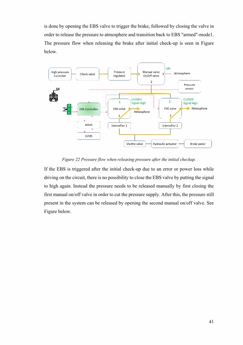
The functionality of the EBS will be tested either by a circuit marshal or during the
initial check-up by triggering the EBS and checking the hydraulic brake pressure. This
41
is done by opening the EBS valve to trigger the brake, followed by closing the valve in
order to release the pressure to atmosphere and transition back to EBS "armed"-mode1.
The pressure flow when releasing the brake after initial check-up is seen in Figure
below.
Figure 22 Pressure flow when releasing pressure after the initial checkup.
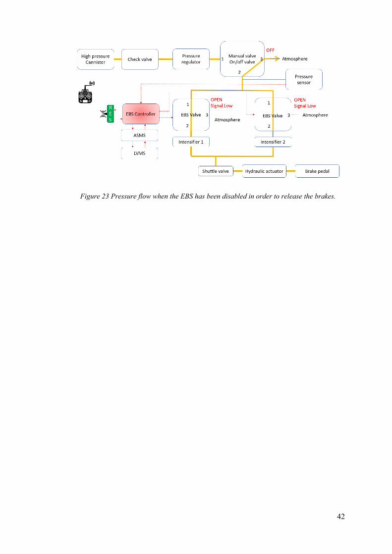
If the EBS is triggered after the initial check-up due to an error or power loss while
driving on the circuit, there is no possibility to close the EBS valve by putting the signal
to high again. Instead the pressure needs to be released manually by first closing the
first manual on/off valve in order to cut the pressure supply. After this, the pressure still
present in the system can be released by opening the second manual on/off valve. See
Figure below.
42
Figure 23 Pressure flow when the EBS has been disabled in order to release the brakes.
43
Chapter 4
This chapter is about estimating the pedal force which must be applied by the actuator
of the EBS, and different cases have been considered for the force selection and
correspondingly the deceleration for all the possible cases.
Pedal force calculation
4.1 Estimation of Pedal force from deceleration
Vehicle data for brake force calculation
1. Vehicle mass (Kg) – 187 (without Autonomous driving components - Steering, EBS, camera etc)
2. Mass of Autonomous driving components – around 3 kg 3. Driver mass (Kg) – 75 4. Wheel base(mm) –1525 5. XG (mm) – 808.25 6. ZG centre of gravity(m) – 247
Hydraulic Torque repartition
1. Hydraulic torque repartition front to rear = 65:35
Electric torque
1. Electric torque repartition front to rear = Hydraulic torque repartition front to rear
Aerodynamics Data
1. Frontal area (m2) -1.16 2. Density of Air (kg/m3) - 1.2 3. CX – 0.9655 4. CZA – -1.504 5. CZP – -1.696
Tyre data
1. Tire Continental C16 - 205/470 R13 2. Nominal wheel radius Front or rear(mm) – 242 3. Loaded radius front or rear(mm) – 237.16
44
4. µ-X Tire front or Rear – 1.8 5. Moment of inertia front or rear(kg-m2) – 0.27
Brake Data
1. Brake disc radius front(mm) – 94 2. Brake disc radius rear(mm) – 83 3. Coefficient of friction(µpad) front or rear – 0.4
Calliper information
1. Font calliper – P4-24 No of pistons – 4 – Diameter 24 mm – Area – 1809 mm2
2. Rear calliper – P2-24 No of pistons – 2 – Diameter 24 mm – Area – 905 mm2
Master Cylinders information
1. Diameter of Master cylinder front – 16 mm 2. Diameter of Master cylinder rear – 16 mm
Pedal box
1. Pedal gain = 3 2. Spring preload = 280 N 3. Balance bar repartition (front to rear) = 50:50(can also be calibrated for further
optimisation, max 60:40)
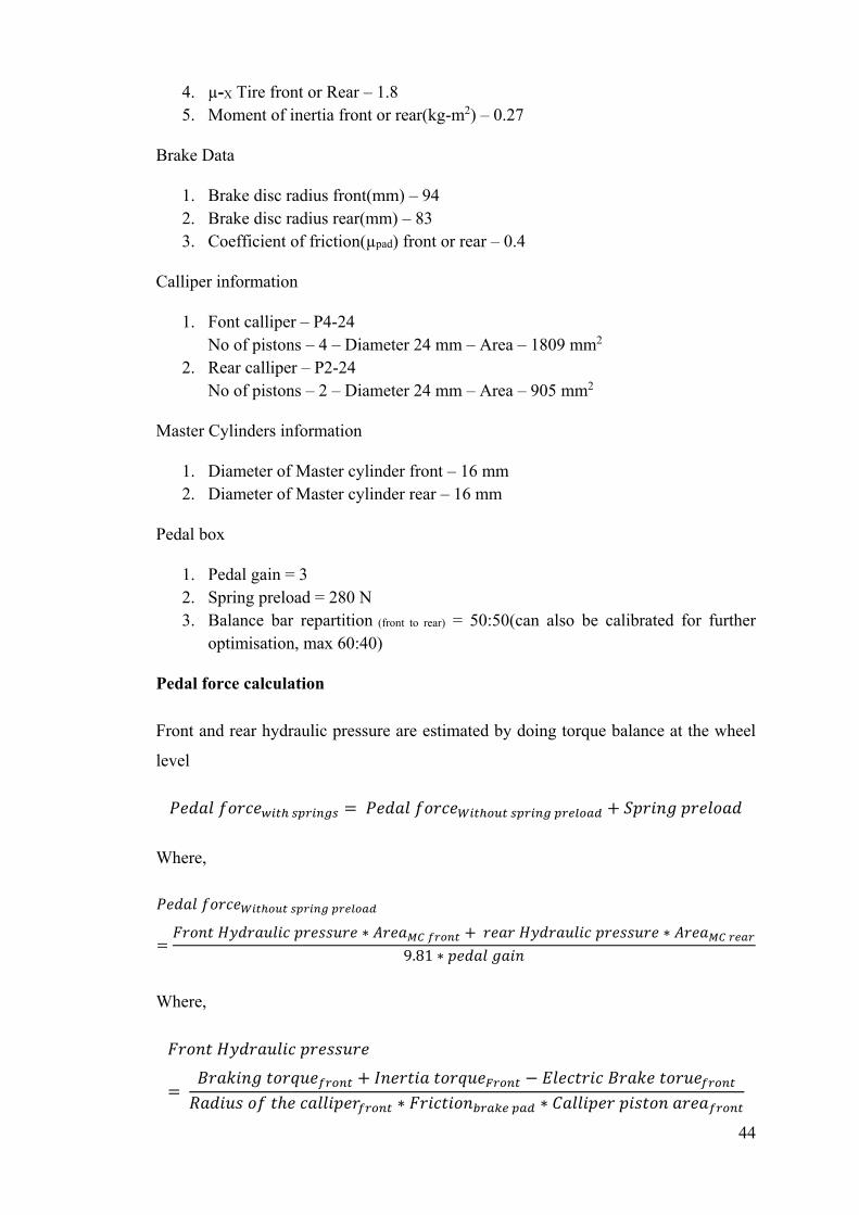
Pedal force calculation
Front and rear hydraulic pressure are estimated by doing torque balance at the wheel
level
𝑃𝑒𝑑𝑎𝑙 𝑓𝑜𝑟𝑐𝑒𝑤𝑖𝑡ℎ 𝑠𝑝𝑟𝑖𝑛𝑔𝑠 = 𝑃𝑒𝑑𝑎𝑙 𝑓𝑜𝑟𝑐𝑒𝑊𝑖𝑡ℎ𝑜𝑢𝑡 𝑠𝑝𝑟𝑖𝑛𝑔 𝑝𝑟𝑒𝑙𝑜𝑎𝑑 + 𝑆𝑝𝑟𝑖𝑛𝑔 𝑝𝑟𝑒𝑙𝑜𝑎𝑑
Where,
𝑃𝑒𝑑𝑎𝑙 𝑓𝑜𝑟𝑐𝑒𝑊𝑖𝑡ℎ𝑜𝑢𝑡 𝑠𝑝𝑟𝑖𝑛𝑔 𝑝𝑟𝑒𝑙𝑜𝑎𝑑
=𝐹𝑟𝑜𝑛𝑡 𝐻𝑦𝑑𝑟𝑎𝑢𝑙𝑖𝑐 𝑝𝑟𝑒𝑠𝑠𝑢𝑟𝑒 ∗ 𝐴𝑟𝑒𝑎𝑀𝐶 𝑓𝑟𝑜𝑛𝑡 + 𝑟𝑒𝑎𝑟 𝐻𝑦𝑑𝑟𝑎𝑢𝑙𝑖𝑐 𝑝𝑟𝑒𝑠𝑠𝑢𝑟𝑒 ∗ 𝐴𝑟𝑒𝑎𝑀𝐶 𝑟𝑒𝑎𝑟
9.81 ∗ 𝑝𝑒𝑑𝑎𝑙 𝑔𝑎𝑖𝑛
Where,
𝐹𝑟𝑜𝑛𝑡 𝐻𝑦𝑑𝑟𝑎𝑢𝑙𝑖𝑐 𝑝𝑟𝑒𝑠𝑠𝑢𝑟𝑒
= 𝐵𝑟𝑎𝑘𝑖𝑛𝑔 𝑡𝑜𝑟𝑞𝑢𝑒𝑓𝑟𝑜𝑛𝑡 + 𝐼𝑛𝑒𝑟𝑡𝑖𝑎 𝑡𝑜𝑟𝑞𝑢𝑒𝐹𝑟𝑜𝑛𝑡 − 𝐸𝑙𝑒𝑐𝑡𝑟𝑖𝑐 𝐵𝑟𝑎𝑘𝑒 𝑡𝑜𝑟𝑢𝑒𝑓𝑟𝑜𝑛𝑡
𝑅𝑎𝑑𝑖𝑢𝑠 𝑜𝑓 𝑡ℎ𝑒 𝑐𝑎𝑙𝑙𝑖𝑝𝑒𝑟𝑓𝑟𝑜𝑛𝑡 ∗ 𝐹𝑟𝑖𝑐𝑡𝑖𝑜𝑛𝑏𝑟𝑎𝑘𝑒 𝑝𝑎𝑑 ∗ 𝐶𝑎𝑙𝑙𝑖𝑝𝑒𝑟 𝑝𝑖𝑠𝑡𝑜𝑛 𝑎𝑟𝑒𝑎𝑓𝑟𝑜𝑛𝑡
45
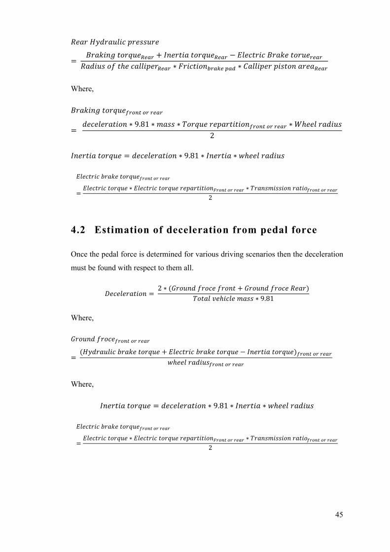
𝑅𝑒𝑎𝑟 𝐻𝑦𝑑𝑟𝑎𝑢𝑙𝑖𝑐 𝑝𝑟𝑒𝑠𝑠𝑢𝑟𝑒
= 𝐵𝑟𝑎𝑘𝑖𝑛𝑔 𝑡𝑜𝑟𝑞𝑢𝑒𝑅𝑒𝑎𝑟 + 𝐼𝑛𝑒𝑟𝑡𝑖𝑎 𝑡𝑜𝑟𝑞𝑢𝑒𝑅𝑒𝑎𝑟 − 𝐸𝑙𝑒𝑐𝑡𝑟𝑖𝑐 𝐵𝑟𝑎𝑘𝑒 𝑡𝑜𝑟𝑢𝑒𝑟𝑒𝑎𝑟
𝑅𝑎𝑑𝑖𝑢𝑠 𝑜𝑓 𝑡ℎ𝑒 𝑐𝑎𝑙𝑙𝑖𝑝𝑒𝑟𝑅𝑒𝑎𝑟 ∗ 𝐹𝑟𝑖𝑐𝑡𝑖𝑜𝑛𝑏𝑟𝑎𝑘𝑒 𝑝𝑎𝑑 ∗ 𝐶𝑎𝑙𝑙𝑖𝑝𝑒𝑟 𝑝𝑖𝑠𝑡𝑜𝑛 𝑎𝑟𝑒𝑎𝑅𝑒𝑎𝑟
Where,
𝐵𝑟𝑎𝑘𝑖𝑛𝑔 𝑡𝑜𝑟𝑞𝑢𝑒𝑓𝑟𝑜𝑛𝑡 𝑜𝑟 𝑟𝑒𝑎𝑟
= 𝑑𝑒𝑐𝑒𝑙𝑒𝑟𝑎𝑡𝑖𝑜𝑛 ∗ 9.81 ∗ 𝑚𝑎𝑠𝑠 ∗ 𝑇𝑜𝑟𝑞𝑢𝑒 𝑟𝑒𝑝𝑎𝑟𝑡𝑖𝑡𝑖𝑜𝑛𝑓𝑟𝑜𝑛𝑡 𝑜𝑟 𝑟𝑒𝑎𝑟 ∗ 𝑊ℎ𝑒𝑒𝑙 𝑟𝑎𝑑𝑖𝑢𝑠
2
𝐼𝑛𝑒𝑟𝑡𝑖𝑎 𝑡𝑜𝑟𝑞𝑢𝑒 = 𝑑𝑒𝑐𝑒𝑙𝑒𝑟𝑎𝑡𝑖𝑜𝑛 ∗ 9.81 ∗ 𝐼𝑛𝑒𝑟𝑡𝑖𝑎 ∗ 𝑤ℎ𝑒𝑒𝑙 𝑟𝑎𝑑𝑖𝑢𝑠
𝐸𝑙𝑒𝑐𝑡𝑟𝑖𝑐 𝑏𝑟𝑎𝑘𝑒 𝑡𝑜𝑟𝑞𝑢𝑒𝑓𝑟𝑜𝑛𝑡 𝑜𝑟 𝑟𝑒𝑎𝑟
=𝐸𝑙𝑒𝑐𝑡𝑟𝑖𝑐 𝑡𝑜𝑟𝑞𝑢𝑒 ∗ 𝐸𝑙𝑒𝑐𝑡𝑟𝑖𝑐 𝑡𝑜𝑟𝑞𝑢𝑒 𝑟𝑒𝑝𝑎𝑟𝑡𝑖𝑡𝑖𝑜𝑛𝐹𝑟𝑜𝑛𝑡 𝑜𝑟 𝑟𝑒𝑎𝑟 ∗ 𝑇𝑟𝑎𝑛𝑠𝑚𝑖𝑠𝑠𝑖𝑜𝑛 𝑟𝑎𝑡𝑖𝑜𝑓𝑟𝑜𝑛𝑡 𝑜𝑟 𝑟𝑒𝑎𝑟
2
4.2 Estimation of deceleration from pedal force
Once the pedal force is determined for various driving scenarios then the deceleration
must be found with respect to them all.
𝐷𝑒𝑐𝑒𝑙𝑒𝑟𝑎𝑡𝑖𝑜𝑛 = 2 ∗ (𝐺𝑟𝑜𝑢𝑛𝑑 𝑓𝑟𝑜𝑐𝑒 𝑓𝑟𝑜𝑛𝑡 + 𝐺𝑟𝑜𝑢𝑛𝑑 𝑓𝑟𝑜𝑐𝑒 𝑅𝑒𝑎𝑟)
𝑇𝑜𝑡𝑎𝑙 𝑣𝑒ℎ𝑖𝑐𝑙𝑒 𝑚𝑎𝑠𝑠 ∗ 9.81
Where,
𝐺𝑟𝑜𝑢𝑛𝑑 𝑓𝑟𝑜𝑐𝑒𝑓𝑟𝑜𝑛𝑡 𝑜𝑟 𝑟𝑒𝑎𝑟
= (𝐻𝑦𝑑𝑟𝑎𝑢𝑙𝑖𝑐 𝑏𝑟𝑎𝑘𝑒 𝑡𝑜𝑟𝑞𝑢𝑒 + 𝐸𝑙𝑒𝑐𝑡𝑟𝑖𝑐 𝑏𝑟𝑎𝑘𝑒 𝑡𝑜𝑟𝑞𝑢𝑒 − 𝐼𝑛𝑒𝑟𝑡𝑖𝑎 𝑡𝑜𝑟𝑞𝑢𝑒)𝑓𝑟𝑜𝑛𝑡 𝑜𝑟 𝑟𝑒𝑎𝑟
𝑤ℎ𝑒𝑒𝑙 𝑟𝑎𝑑𝑖𝑢𝑠𝑓𝑟𝑜𝑛𝑡 𝑜𝑟 𝑟𝑒𝑎𝑟
Where,
𝐼𝑛𝑒𝑟𝑡𝑖𝑎 𝑡𝑜𝑟𝑞𝑢𝑒 = 𝑑𝑒𝑐𝑒𝑙𝑒𝑟𝑎𝑡𝑖𝑜𝑛 ∗ 9.81 ∗ 𝐼𝑛𝑒𝑟𝑡𝑖𝑎 ∗ 𝑤ℎ𝑒𝑒𝑙 𝑟𝑎𝑑𝑖𝑢𝑠
𝐸𝑙𝑒𝑐𝑡𝑟𝑖𝑐 𝑏𝑟𝑎𝑘𝑒 𝑡𝑜𝑟𝑞𝑢𝑒𝑓𝑟𝑜𝑛𝑡 𝑜𝑟 𝑟𝑒𝑎𝑟
=𝐸𝑙𝑒𝑐𝑡𝑟𝑖𝑐 𝑡𝑜𝑟𝑞𝑢𝑒 ∗ 𝐸𝑙𝑒𝑐𝑡𝑟𝑖𝑐 𝑡𝑜𝑟𝑞𝑢𝑒 𝑟𝑒𝑝𝑎𝑟𝑡𝑖𝑡𝑖𝑜𝑛𝐹𝑟𝑜𝑛𝑡 𝑜𝑟 𝑟𝑒𝑎𝑟 ∗ 𝑇𝑟𝑎𝑛𝑠𝑚𝑖𝑠𝑠𝑖𝑜𝑛 𝑟𝑎𝑡𝑖𝑜𝑓𝑟𝑜𝑛𝑡 𝑜𝑟 𝑟𝑒𝑎𝑟
2
46
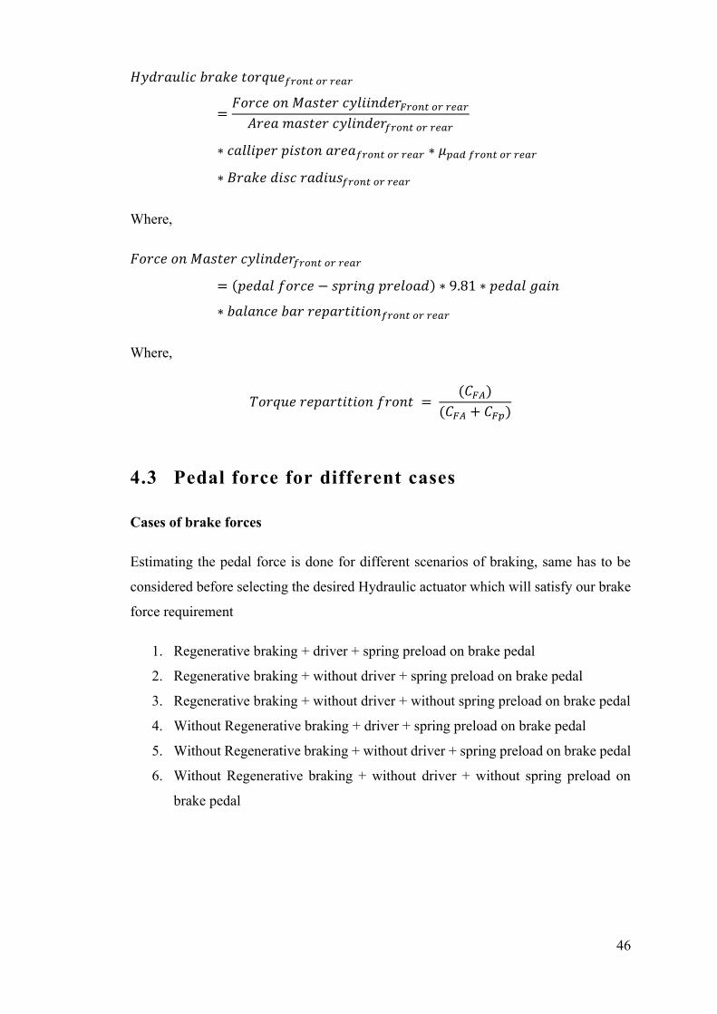
𝐻𝑦𝑑𝑟𝑎𝑢𝑙𝑖𝑐 𝑏𝑟𝑎𝑘𝑒 𝑡𝑜𝑟𝑞𝑢𝑒𝑓𝑟𝑜𝑛𝑡 𝑜𝑟 𝑟𝑒𝑎𝑟
=𝐹𝑜𝑟𝑐𝑒 𝑜𝑛 𝑀𝑎𝑠𝑡𝑒𝑟 𝑐𝑦𝑙𝑖𝑖𝑛𝑑𝑒𝑟𝐹𝑟𝑜𝑛𝑡 𝑜𝑟 𝑟𝑒𝑎𝑟
𝐴𝑟𝑒𝑎 𝑚𝑎𝑠𝑡𝑒𝑟 𝑐𝑦𝑙𝑖𝑛𝑑𝑒𝑟𝑓𝑟𝑜𝑛𝑡 𝑜𝑟 𝑟𝑒𝑎𝑟
∗ 𝑐𝑎𝑙𝑙𝑖𝑝𝑒𝑟 𝑝𝑖𝑠𝑡𝑜𝑛 𝑎𝑟𝑒𝑎𝑓𝑟𝑜𝑛𝑡 𝑜𝑟 𝑟𝑒𝑎𝑟 ∗ 𝜇𝑝𝑎𝑑 𝑓𝑟𝑜𝑛𝑡 𝑜𝑟 𝑟𝑒𝑎𝑟
∗ 𝐵𝑟𝑎𝑘𝑒 𝑑𝑖𝑠𝑐 𝑟𝑎𝑑𝑖𝑢𝑠𝑓𝑟𝑜𝑛𝑡 𝑜𝑟 𝑟𝑒𝑎𝑟
Where,
𝐹𝑜𝑟𝑐𝑒 𝑜𝑛 𝑀𝑎𝑠𝑡𝑒𝑟 𝑐𝑦𝑙𝑖𝑛𝑑𝑒𝑟𝑓𝑟𝑜𝑛𝑡 𝑜𝑟 𝑟𝑒𝑎𝑟
= (𝑝𝑒𝑑𝑎𝑙 𝑓𝑜𝑟𝑐𝑒 − 𝑠𝑝𝑟𝑖𝑛𝑔 𝑝𝑟𝑒𝑙𝑜𝑎𝑑) ∗ 9.81 ∗ 𝑝𝑒𝑑𝑎𝑙 𝑔𝑎𝑖𝑛
∗ 𝑏𝑎𝑙𝑎𝑛𝑐𝑒 𝑏𝑎𝑟 𝑟𝑒𝑝𝑎𝑟𝑡𝑖𝑡𝑖𝑜𝑛𝑓𝑟𝑜𝑛𝑡 𝑜𝑟 𝑟𝑒𝑎𝑟
Where,
𝑇𝑜𝑟𝑞𝑢𝑒 𝑟𝑒𝑝𝑎𝑟𝑡𝑖𝑡𝑖𝑜𝑛 𝑓𝑟𝑜𝑛𝑡 = (𝐶𝐹𝐴)
(𝐶𝐹𝐴 + 𝐶𝐹𝑝)
4.3 Pedal force for different cases
Cases of brake forces
Estimating the pedal force is done for different scenarios of braking, same has to be
considered before selecting the desired Hydraulic actuator which will satisfy our brake
force requirement
1. Regenerative braking + driver + spring preload on brake pedal
2. Regenerative braking + without driver + spring preload on brake pedal
3. Regenerative braking + without driver + without spring preload on brake pedal
4. Without Regenerative braking + driver + spring preload on brake pedal
5. Without Regenerative braking + without driver + spring preload on brake pedal
6. Without Regenerative braking + without driver + without spring preload on
brake pedal
47
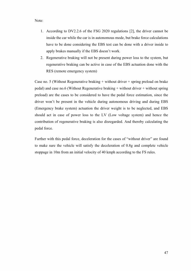
Note:
1. According to DV2.2.6 of the FSG 2020 regulations [2], the driver cannot be
inside the car while the car is in autonomous mode, but brake force calculations
have to be done considering the EBS test can be done with a driver inside to
apply brakes manually if the EBS doesn’t work.
2. Regenerative braking will not be present during power loss to the system, but
regenerative braking can be active in case of the EBS actuation done with the
RES (remote emergency system)
Case no. 5 (Without Regenerative braking + without driver + spring preload on brake
pedal) and case no.6 (Without Regenerative braking + without driver + without spring
preload) are the cases to be considered to have the pedal force estimation, since the
driver won’t be present in the vehicle during autonomous driving and during EBS
(Emergency brake system) actuation the driver weight is to be neglected, and EBS
should act in case of power loss to the LV (Low voltage system) and hence the
contribution of regenerative braking is also disregarded. And thereby calculating the
pedal force.
Further with this pedal force, deceleration for the cases of “without driver” are found
to make sure the vehicle will satisfy the deceleration of 0.8g and complete vehicle
stoppage in 10m from an initial velocity of 40 kmph according to the FS rules.
48
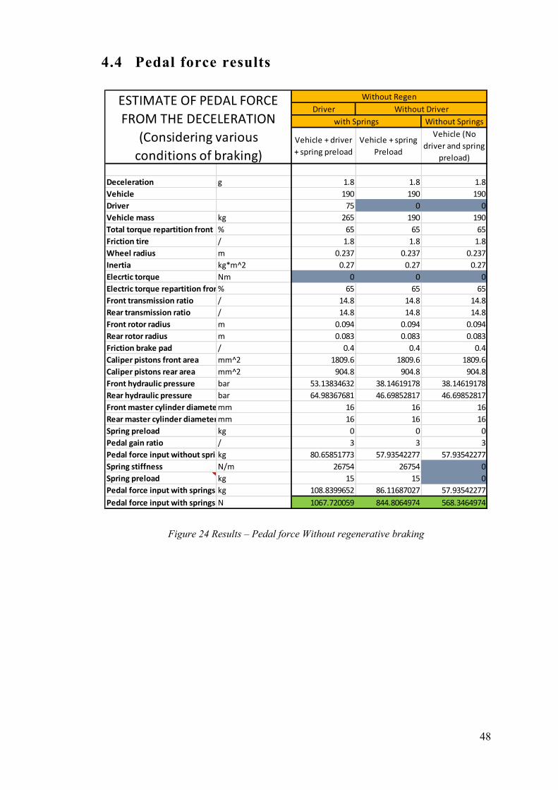
4.4 Pedal force results
Figure 24 Results – Pedal force Without regenerative braking
Driver
Without Springs
Vehicle + driver
+ spring preload
Vehicle + spring
Preload
Vehicle (No
driver and spring
preload)
Deceleration g 1.8 1.8 1.8
Vehicle 190 190 190
Driver 75 0 0
Vehicle mass kg 265 190 190
Total torque repartition front % 65 65 65
Friction tire / 1.8 1.8 1.8
Wheel radius m 0.237 0.237 0.237
Inertia kg*m^2 0.27 0.27 0.27
Elecrtic torque Nm 0 0 0
Electric torque repartition front% 65 65 65
Front transmission ratio / 14.8 14.8 14.8
Rear transmission ratio / 14.8 14.8 14.8
Front rotor radius m 0.094 0.094 0.094
Rear rotor radius m 0.083 0.083 0.083
Friction brake pad / 0.4 0.4 0.4
Caliper pistons front area mm^2 1809.6 1809.6 1809.6
Caliper pistons rear area mm^2 904.8 904.8 904.8
Front hydraulic pressure bar 53.13834632 38.14619178 38.14619178
Rear hydraulic pressure bar 64.98367681 46.69852817 46.69852817
Front master cylinder diametermm 16 16 16
Rear master cylinder diametermm 16 16 16
Spring preload kg 0 0 0
Pedal gain ratio / 3 3 3
Pedal force input without springskg 80.65851773 57.93542277 57.93542277
Spring stiffness N/m 26754 26754 0
Spring preload kg 15 15 0
Pedal force input with springs kg 108.8399652 86.11687027 57.93542277
Pedal force input with springs N 1067.720059 844.8064974 568.3464974
with Springs
Without Regen
Without DriverESTIMATE OF PEDAL FORCE
FROM THE DECELERATION
(Considering various
conditions of braking)
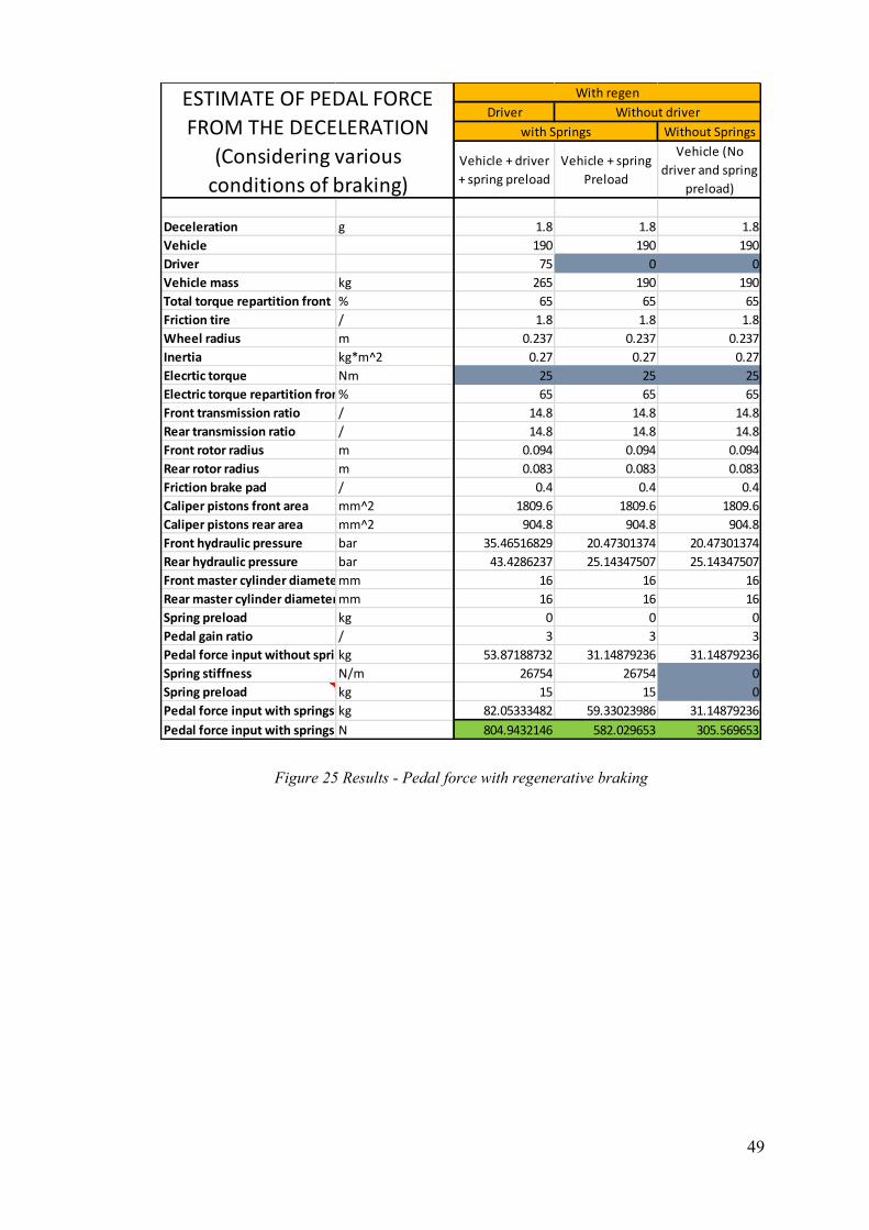
49
Figure 25 Results - Pedal force with regenerative braking
Driver
Without Springs
Vehicle + driver
+ spring preload
Vehicle + spring
Preload
Vehicle (No
driver and spring
preload)
Deceleration g 1.8 1.8 1.8
Vehicle 190 190 190
Driver 75 0 0
Vehicle mass kg 265 190 190
Total torque repartition front % 65 65 65
Friction tire / 1.8 1.8 1.8
Wheel radius m 0.237 0.237 0.237
Inertia kg*m^2 0.27 0.27 0.27
Elecrtic torque Nm 25 25 25
Electric torque repartition front% 65 65 65
Front transmission ratio / 14.8 14.8 14.8
Rear transmission ratio / 14.8 14.8 14.8
Front rotor radius m 0.094 0.094 0.094
Rear rotor radius m 0.083 0.083 0.083
Friction brake pad / 0.4 0.4 0.4
Caliper pistons front area mm^2 1809.6 1809.6 1809.6
Caliper pistons rear area mm^2 904.8 904.8 904.8
Front hydraulic pressure bar 35.46516829 20.47301374 20.47301374
Rear hydraulic pressure bar 43.4286237 25.14347507 25.14347507
Front master cylinder diametermm 16 16 16
Rear master cylinder diametermm 16 16 16
Spring preload kg 0 0 0
Pedal gain ratio / 3 3 3
Pedal force input without springskg 53.87188732 31.14879236 31.14879236
Spring stiffness N/m 26754 26754 0
Spring preload kg 15 15 0
Pedal force input with springs kg 82.05333482 59.33023986 31.14879236
Pedal force input with springs N 804.9432146 582.029653 305.569653
ESTIMATE OF PEDAL FORCE
FROM THE DECELERATION
(Considering various
conditions of braking)
With regen
Without driver
with Springs
50
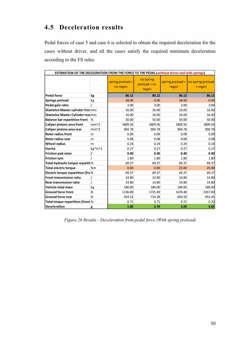
4.5 Deceleration results
Pedal forces of case 5 and case 6 is selected to obtain the required deceleration for the
cases without driver, and all the cases satisfy the required minimum deceleration
according to the FS rules.
Figure 26 Results - Deceleration from pedal force (With spring preload)
spring preload +
no regen
no Spring
preload + no
regen
spring preload +
regen
no spring preload
+ regen
Pedal force kg 86.12 86.12 86.12 86.12
Springs preload kg 28.00 0.00 28.00 0.00
Pedal gain ratio / 3.00 3.00 3.00 3.00
Diametro Master cylinder frontmm 16.00 16.00 16.00 16.00
Diametro Master Cylinder rearmm 16.00 16.00 16.00 16.00
Balance bar repartition front % 50.00 50.00 50.00 50.00
Caliper pistons area front mm^2 1809.56 1809.56 1809.56 1809.56
Caliper pistons area rear mm^2 904.78 904.78 904.78 904.78
Rotor radius front m 0.09 0.09 0.09 0.09
Rotor radius rear m 0.08 0.08 0.08 0.08
Wheel radius m 0.24 0.24 0.24 0.24
Inertia kg*m^2 0.27 0.27 0.27 0.27
Friction pad-rotor / 0.40 0.40 0.40 0.40
Friction tyre / 1.80 1.80 1.80 1.80
Total hydraulic torque repartition [front]% 69.37 69.37 69.37 69.37
Total electric torque Nm 0.00 0.00 25.00 25.00
Electric torque repartition [front]% 69.37 69.37 69.37 69.37
Front transmission ratio / 14.80 14.80 14.80 14.80
Rear transmission ratio / 14.80 14.80 14.80 14.80
Vehicle total mass kg 180.00 180.00 180.00 180.00
Ground force front N 1136.89 1725.49 1678.40 2267.00
Ground force rear N 454.52 714.38 693.59 953.45
Total torque repartition [front]% 0.71 0.71 0.71 0.70
Deceleration g 1.80 2.76 2.69 3.65
ESTIMATION OF THE DECELERATION FROM THE FORCE TO THE PEDAL (without driver and with springs)
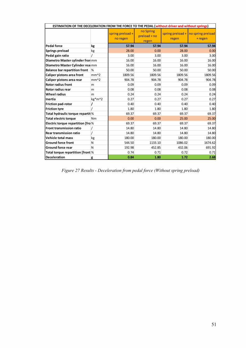
51
Figure 27 Results - Deceleration from pedal force (Without spring preload)
spring preload +
no regen
no Spring
preload + no
regen
spring preload +
regen
no spring preload
+ regen
Pedal force kg 57.94 57.94 57.94 57.94
Springs preload kg 28.00 0.00 28.00 0.00
Pedal gain ratio / 3.00 3.00 3.00 3.00
Diametro Master cylinder frontmm 16.00 16.00 16.00 16.00
Diametro Master Cylinder rearmm 16.00 16.00 16.00 16.00
Balance bar repartition front % 50.00 50.00 50.00 50.00
Caliper pistons area front mm^2 1809.56 1809.56 1809.56 1809.56
Caliper pistons area rear mm^2 904.78 904.78 904.78 904.78
Rotor radius front m 0.09 0.09 0.09 0.09
Rotor radius rear m 0.08 0.08 0.08 0.08
Wheel radius m 0.24 0.24 0.24 0.24
Inertia kg*m^2 0.27 0.27 0.27 0.27
Friction pad-rotor / 0.40 0.40 0.40 0.40
Friction tyre / 1.80 1.80 1.80 1.80
Total hydraulic torque repartition [front]% 69.37 69.37 69.37 69.37
Total electric torque Nm 0.00 0.00 25.00 25.00
Electric torque repartition [front]% 69.37 69.37 69.37 69.37
Front transmission ratio / 14.80 14.80 14.80 14.80
Rear transmission ratio / 14.80 14.80 14.80 14.80
Vehicle total mass kg 180.00 180.00 180.00 180.00
Ground force front N 544.50 1133.10 1086.02 1674.62
Ground force rear N 192.98 452.85 432.06 691.92
Total torque repartition [front]% 0.74 0.71 0.72 0.71
Deceleration g 0.84 1.80 1.72 2.68
ESTIMATION OF THE DECELERATION FROM THE FORCE TO THE PEDAL (without driver and without springs)
52
Chapter 5
This chapter deals with the calculations regarding the placement of actuator behind the
brake pedal, calculations for solution using Pneumatic actuator which is not compatible
due to oversize of the actuator and the calculations for using a Hydro-Pneumatic
arrangement for the EBS.
Calculation for EBS components
5.1 Calculations for actuator placement
Any actuator can have specifications as
1. Force that the actuator provides during pulling – depends upon inclination
2. Stroke of the actuator – depends upon pedal travel
The above specifications becomes a function of geometry in our pedal box arrangement
on how the actuator is placed, it more or less looks like an inversion of slider crank
mechanism, to estimate the exact force and stroke of the actuator a kinematic study of
the hard points have to be done either using a drawing tool like Catia or using basic
geometrical formulas.
53
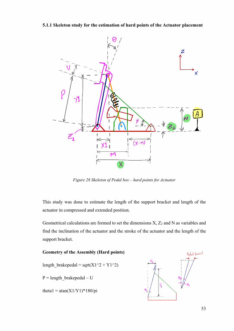
5.1.1 Skeleton study for the estimation of hard points of the Actuator placement
Figure 28 Skeleton of Pedal box – hard points for Actuator
This study was done to estimate the length of the support bracket and length of the
actuator in compressed and extended position.
Geometrical calculations are formed to set the dimensions X, Z2 and N as variables and
find the inclination of the actuator and the stroke of the actuator and the length of the
support bracket.
Geometry of the Assembly (Hard points)
length_brakepedal = sqrt(X1^2 + Y1^2)
P = length_brakepedal – U
theta1 = atan(X1/Y1)*180/pi
54
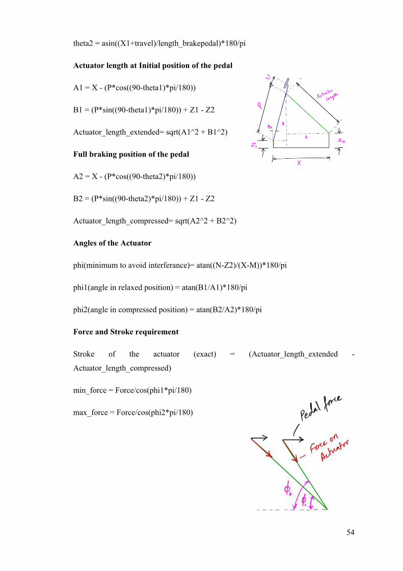
theta2 = asin((X1+travel)/length_brakepedal)*180/pi
Actuator length at Initial position of the pedal
A1 = X - (P*cos((90-theta1)*pi/180))
B1 = (P*sin((90-theta1)*pi/180)) + Z1 - Z2
Actuator_length_extended= sqrt(A1^2 + B1^2)
Full braking position of the pedal
A2 = X - (P*cos((90-theta2)*pi/180))
B2 = (P*sin((90-theta2)*pi/180)) + Z1 - Z2
Actuator_length_compressed= sqrt(A2^2 + B2^2)
Angles of the Actuator
phi(minimum to avoid interferance)= atan((N-Z2)/(X-M))*180/pi
phi1(angle in relaxed position) = atan(B1/A1)*180/pi
phi2(angle in compressed position) = atan(B2/A2)*180/pi
Force and Stroke requirement
Stroke of the actuator (exact) = (Actuator_length_extended -
Actuator_length_compressed)
min_force = Force/cos(phi1*pi/180)
max_force = Force/cos(phi2*pi/180)

55
5.1.2 Estimation of the stroke and actuator placement using CAD drawings
Stroke length estimation
Using Catia drawing environment, the stroke and force requirement is done to have a
matching with the skeleton study
Figure 29 Pedal travel for BOTS actuation
Above figure shows the pedal travel required for the pressing of the BOTS (Brake over
travel switch) in case of loss of pressure in the Brake line. the maximum brake travel is
25 mm for full brake actuation and 38 mm is the brake travel required for the actuation
of the BOTS which is connected to the shutdown circuit.
Figure 30 Actuator stroke for full braking and BOTS actuation
56
The above figure shows that for a 25 mm of the pedal travel we require the actuator
stroke should be 186.715 – 168.992 = 18 mm and for a pedal travel of 37 mm (required
for BOTS actuation) we need a stroke of 186.715 – 159.775 = 27 mm and with tolerance
of 2 mm, we selected an actuator with 29~30 mm.
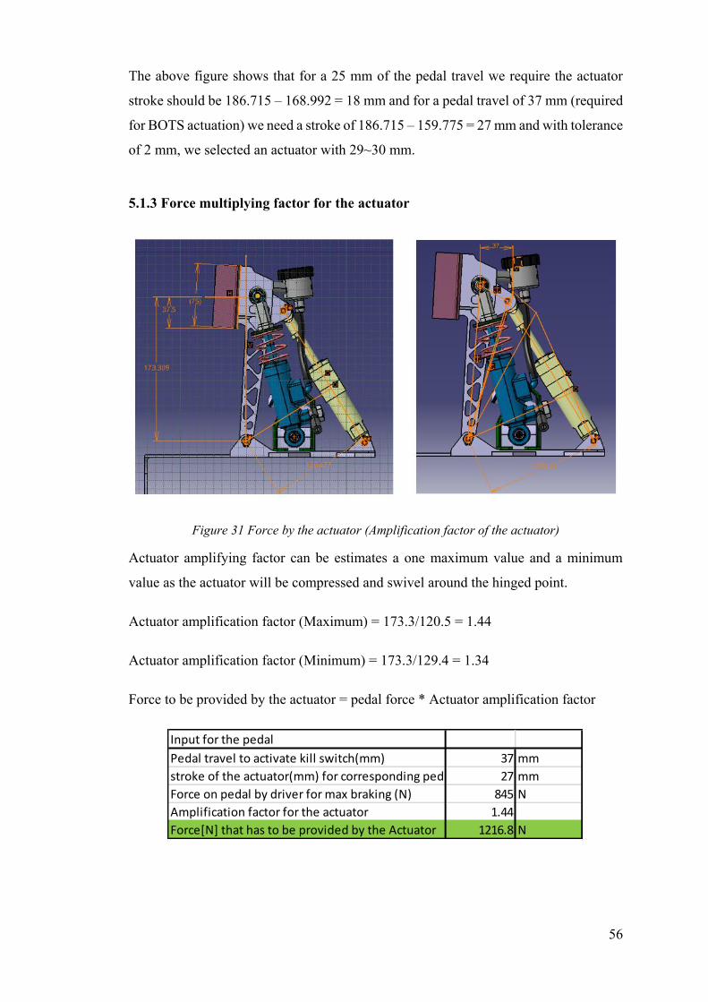
5.1.3 Force multiplying factor for the actuator
Figure 31 Force by the actuator (Amplification factor of the actuator)
Actuator amplifying factor can be estimates a one maximum value and a minimum
value as the actuator will be compressed and swivel around the hinged point.
Actuator amplification factor (Maximum) = 173.3/120.5 = 1.44
Actuator amplification factor (Minimum) = 173.3/129.4 = 1.34
Force to be provided by the actuator = pedal force * Actuator amplification factor
Input for the pedal
Pedal travel to activate kill switch(mm) 37 mm
stroke of the actuator(mm) for corresponding pedal travel 27 mm
Force on pedal by driver for max braking (N) 845 N
Amplification factor for the actuator 1.44
Force[N] that has to be provided by the Actuator 1216.8 N
57
Load factor of the Brake actuator due to actuation rate
According to the Formula student regulations the brake actuation has to be happened
with a maximum time of 200 milli seconds, and due to such high actuation rated
hydraulic actuators cannot provide the desired force, hence they have to be calibrated
with a load factor of 60 percent [3]
𝑇ℎ𝑒𝑜𝑟𝑒𝑡𝑖𝑐𝑎𝑙 𝑙𝑜𝑎𝑑 =𝐴𝑐𝑡𝑢𝑎𝑙 𝑙𝑜𝑎𝑑
0.6
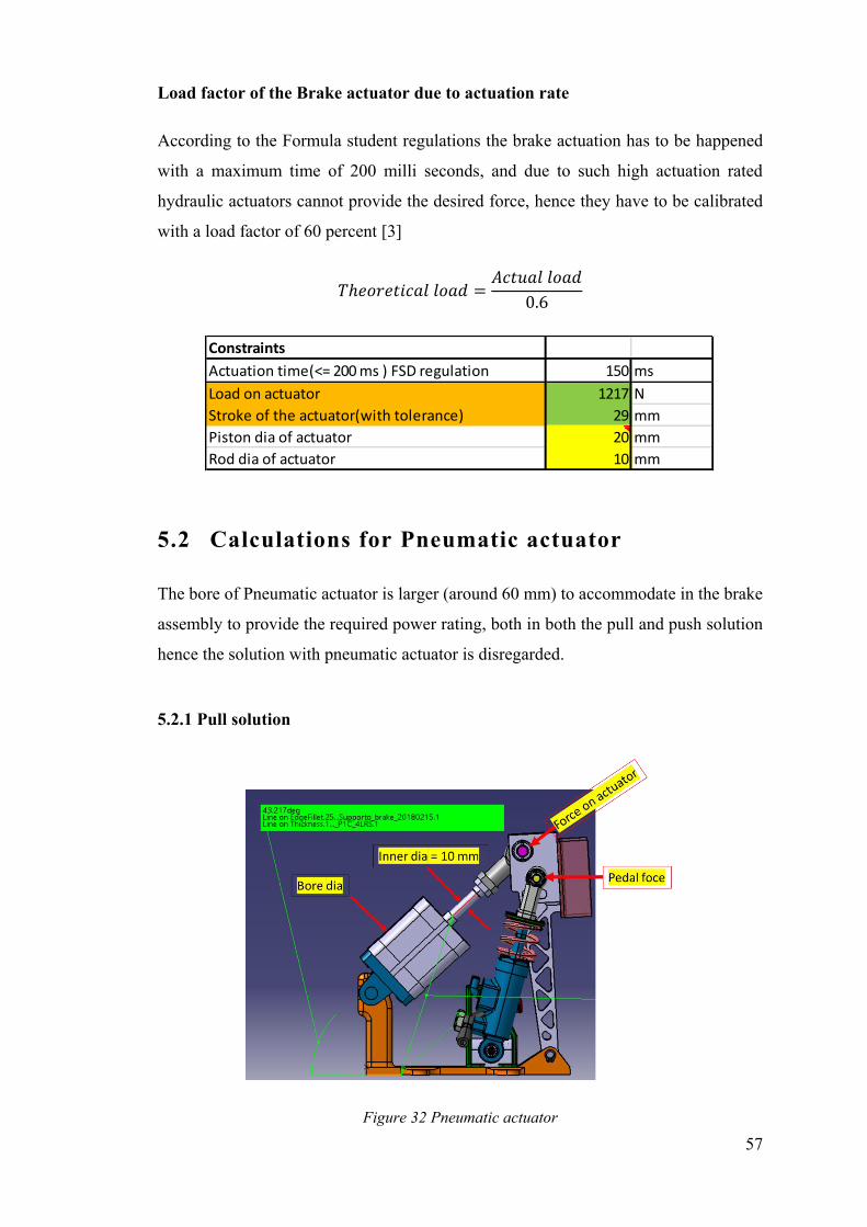
5.2 Calculations for Pneumatic actuator
The bore of Pneumatic actuator is larger (around 60 mm) to accommodate in the brake
assembly to provide the required power rating, both in both the pull and push solution
hence the solution with pneumatic actuator is disregarded.
5.2.1 Pull solution
Figure 32 Pneumatic actuator
Constraints
Actuation time(<= 200 ms ) FSD regulation 150 ms
Load on actuator 1217 N
Stroke of the actuator(with tolerance) 29 mm
Piston dia of actuator 20 mm
Rod dia of actuator 10 mm
58
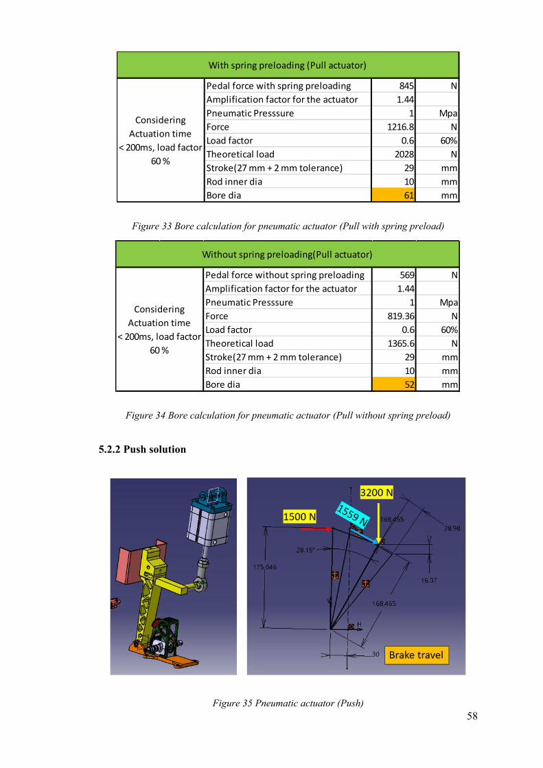
Figure 33 Bore calculation for pneumatic actuator (Pull with spring preload)
Figure 34 Bore calculation for pneumatic actuator (Pull without spring preload)
5.2.2 Push solution
Figure 35 Pneumatic actuator (Push)
Pedal force with spring preloading 845 N
Amplification factor for the actuator 1.44
Pneumatic Presssure 1 Mpa
Force 1216.8 N
Load factor 0.6 60%
Theoretical load 2028 N
Stroke(27 mm + 2 mm tolerance) 29 mm
Rod inner dia 10 mm
Bore dia 61 mm
Considering
Actuation time
< 200ms, load factor
60 %
With spring preloading (Pull actuator)
Pedal force without spring preloading 569 N
Amplification factor for the actuator 1.44
Pneumatic Presssure 1 Mpa
Force 819.36 N
Load factor 0.6 60%
Theoretical load 1365.6 N
Stroke(27 mm + 2 mm tolerance) 29 mm
Rod inner dia 10 mm
Bore dia 52 mm
Without spring preloading(Pull actuator)
Considering
Actuation time
< 200ms, load factor
60 %
59
Push solution for pneumatic actuator requires a bigger force requirement, hence this
cannot be implemented.
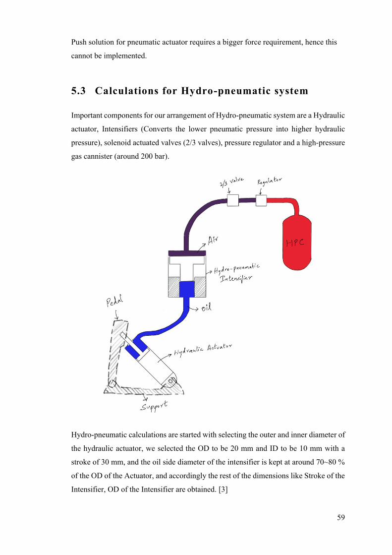
5.3 Calculations for Hydro-pneumatic system
Important components for our arrangement of Hydro-pneumatic system are a Hydraulic
actuator, Intensifiers (Converts the lower pneumatic pressure into higher hydraulic
pressure), solenoid actuated valves (2/3 valves), pressure regulator and a high-pressure
gas cannister (around 200 bar).
Hydro-pneumatic calculations are started with selecting the outer and inner diameter of
the hydraulic actuator, we selected the OD to be 20 mm and ID to be 10 mm with a
stroke of 30 mm, and the oil side diameter of the intensifier is kept at around 70~80 %
of the OD of the Actuator, and accordingly the rest of the dimensions like Stroke of the
Intensifier, OD of the Intensifier are obtained. [3]
60
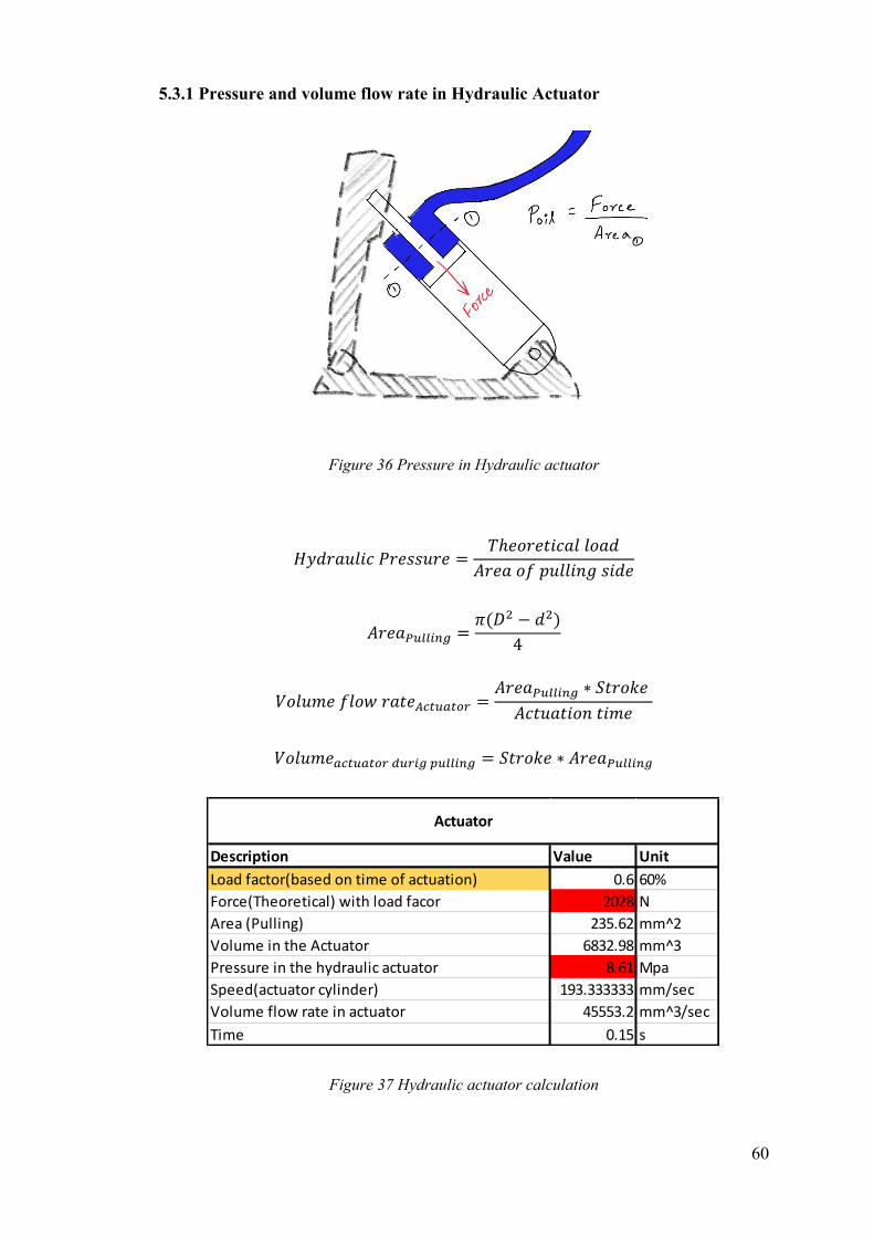
5.3.1 Pressure and volume flow rate in Hydraulic Actuator
Figure 36 Pressure in Hydraulic actuator
𝐻𝑦𝑑𝑟𝑎𝑢𝑙𝑖𝑐 𝑃𝑟𝑒𝑠𝑠𝑢𝑟𝑒 =𝑇ℎ𝑒𝑜𝑟𝑒𝑡𝑖𝑐𝑎𝑙 𝑙𝑜𝑎𝑑
𝐴𝑟𝑒𝑎 𝑜𝑓 𝑝𝑢𝑙𝑙𝑖𝑛𝑔 𝑠𝑖𝑑𝑒
𝐴𝑟𝑒𝑎𝑃𝑢𝑙𝑙𝑖𝑛𝑔 =𝜋(𝐷2 − 𝑑2)
4
𝑉𝑜𝑙𝑢𝑚𝑒 𝑓𝑙𝑜𝑤 𝑟𝑎𝑡𝑒𝐴𝑐𝑡𝑢𝑎𝑡𝑜𝑟 =𝐴𝑟𝑒𝑎𝑃𝑢𝑙𝑙𝑖𝑛𝑔 ∗ 𝑆𝑡𝑟𝑜𝑘𝑒
𝐴𝑐𝑡𝑢𝑎𝑡𝑖𝑜𝑛 𝑡𝑖𝑚𝑒
𝑉𝑜𝑙𝑢𝑚𝑒𝑎𝑐𝑡𝑢𝑎𝑡𝑜𝑟 𝑑𝑢𝑟𝑖𝑔 𝑝𝑢𝑙𝑙𝑖𝑛𝑔 = 𝑆𝑡𝑟𝑜𝑘𝑒 ∗ 𝐴𝑟𝑒𝑎𝑃𝑢𝑙𝑙𝑖𝑛𝑔
Figure 37 Hydraulic actuator calculation
Description Value Unit
Load factor(based on time of actuation) 0.6 60%
Force(Theoretical) with load facor 2028 N
Area (Pulling) 235.62 mm^2
Volume in the Actuator 6832.98 mm^3
Pressure in the hydraulic actuator 8.61 Mpa
Speed(actuator cylinder) 193.333333 mm/sec
Volume flow rate in actuator 45553.2 mm^3/sec
Time 0.15 s
Actuator
61
Design pressure of the actuator can be as high as 300 bar since the actuator is made of
high strength material, according to our calculation the pressure inside the actuator was
around 65 to 120 bar based on our force requirement
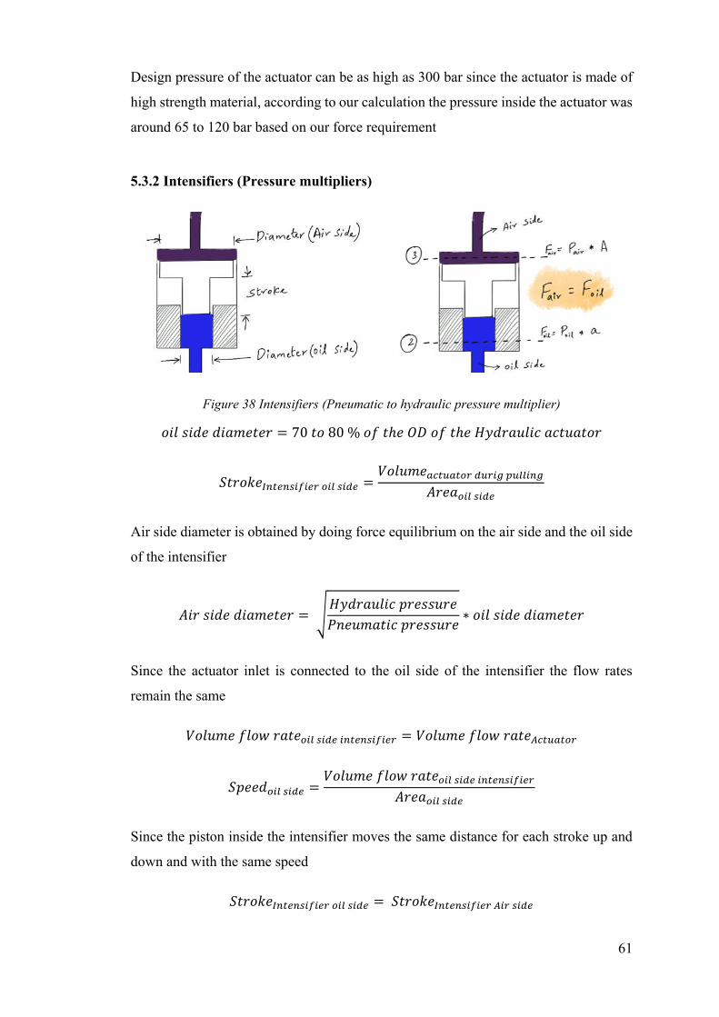
5.3.2 Intensifiers (Pressure multipliers)
Figure 38 Intensifiers (Pneumatic to hydraulic pressure multiplier)
𝑜𝑖𝑙 𝑠𝑖𝑑𝑒 𝑑𝑖𝑎𝑚𝑒𝑡𝑒𝑟 = 70 𝑡𝑜 80 % 𝑜𝑓 𝑡ℎ𝑒 𝑂𝐷 𝑜𝑓 𝑡ℎ𝑒 𝐻𝑦𝑑𝑟𝑎𝑢𝑙𝑖𝑐 𝑎𝑐𝑡𝑢𝑎𝑡𝑜𝑟
𝑆𝑡𝑟𝑜𝑘𝑒𝐼𝑛𝑡𝑒𝑛𝑠𝑖𝑓𝑖𝑒𝑟 𝑜𝑖𝑙 𝑠𝑖𝑑𝑒 =𝑉𝑜𝑙𝑢𝑚𝑒𝑎𝑐𝑡𝑢𝑎𝑡𝑜𝑟 𝑑𝑢𝑟𝑖𝑔 𝑝𝑢𝑙𝑙𝑖𝑛𝑔
𝐴𝑟𝑒𝑎𝑜𝑖𝑙 𝑠𝑖𝑑𝑒
Air side diameter is obtained by doing force equilibrium on the air side and the oil side
of the intensifier
𝐴𝑖𝑟 𝑠𝑖𝑑𝑒 𝑑𝑖𝑎𝑚𝑒𝑡𝑒𝑟 = √𝐻𝑦𝑑𝑟𝑎𝑢𝑙𝑖𝑐 𝑝𝑟𝑒𝑠𝑠𝑢𝑟𝑒
𝑃𝑛𝑒𝑢𝑚𝑎𝑡𝑖𝑐 𝑝𝑟𝑒𝑠𝑠𝑢𝑟𝑒∗ 𝑜𝑖𝑙 𝑠𝑖𝑑𝑒 𝑑𝑖𝑎𝑚𝑒𝑡𝑒𝑟
Since the actuator inlet is connected to the oil side of the intensifier the flow rates
remain the same
𝑉𝑜𝑙𝑢𝑚𝑒 𝑓𝑙𝑜𝑤 𝑟𝑎𝑡𝑒𝑜𝑖𝑙 𝑠𝑖𝑑𝑒 𝑖𝑛𝑡𝑒𝑛𝑠𝑖𝑓𝑖𝑒𝑟 = 𝑉𝑜𝑙𝑢𝑚𝑒 𝑓𝑙𝑜𝑤 𝑟𝑎𝑡𝑒𝐴𝑐𝑡𝑢𝑎𝑡𝑜𝑟
𝑆𝑝𝑒𝑒𝑑𝑜𝑖𝑙 𝑠𝑖𝑑𝑒 =𝑉𝑜𝑙𝑢𝑚𝑒 𝑓𝑙𝑜𝑤 𝑟𝑎𝑡𝑒𝑜𝑖𝑙 𝑠𝑖𝑑𝑒 𝑖𝑛𝑡𝑒𝑛𝑠𝑖𝑓𝑖𝑒𝑟
𝐴𝑟𝑒𝑎𝑜𝑖𝑙 𝑠𝑖𝑑𝑒
Since the piston inside the intensifier moves the same distance for each stroke up and
down and with the same speed
𝑆𝑡𝑟𝑜𝑘𝑒𝐼𝑛𝑡𝑒𝑛𝑠𝑖𝑓𝑖𝑒𝑟 𝑜𝑖𝑙 𝑠𝑖𝑑𝑒 = 𝑆𝑡𝑟𝑜𝑘𝑒𝐼𝑛𝑡𝑒𝑛𝑠𝑖𝑓𝑖𝑒𝑟 𝐴𝑖𝑟 𝑠𝑖𝑑𝑒
62
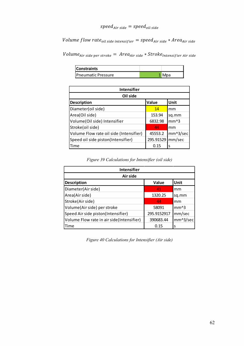
𝑠𝑝𝑒𝑒𝑑𝐴𝑖𝑟 𝑠𝑖𝑑𝑒 = 𝑠𝑝𝑒𝑒𝑑𝑜𝑖𝑙 𝑠𝑖𝑑𝑒
𝑉𝑜𝑙𝑢𝑚𝑒 𝑓𝑙𝑜𝑤 𝑟𝑎𝑡𝑒𝑜𝑖𝑙 𝑠𝑖𝑑𝑒 𝑖𝑛𝑡𝑒𝑛𝑠𝑖𝑓𝑖𝑒𝑟 = 𝑠𝑝𝑒𝑒𝑑𝐴𝑖𝑟 𝑠𝑖𝑑𝑒 ∗ 𝐴𝑟𝑒𝑎𝐴𝑖𝑟 𝑠𝑖𝑑𝑒
𝑉𝑜𝑙𝑢𝑚𝑒𝐴𝑖𝑟 𝑠𝑖𝑑𝑒 𝑝𝑒𝑟 𝑠𝑡𝑟𝑜𝑘𝑒 = 𝐴𝑟𝑒𝑎𝐴𝑖𝑟 𝑠𝑖𝑑𝑒 ∗ 𝑆𝑡𝑟𝑜𝑘𝑒𝐼𝑛𝑡𝑒𝑛𝑠𝑖𝑓𝑖𝑒𝑟 𝐴𝑖𝑟 𝑠𝑖𝑑𝑒
Figure 39 Calculations for Intensifier (oil side)
Figure 40 Calculations for Intensifier (Air side)
Constraints
Pneumatic Pressure 1 Mpa
Description Value Unit
Diameter(oil side) 14 mm
Area(Oil side) 153.94 sq.mm
Volume(Oil side) Intensifier 6832.98 mm^3
Stroke(oil side) 44 mm
Volume Flow rate oil side (Intensifier) 45553.2 mm^3/sec
Speed oil side piston(Intensifier) 295.91529 mm/sec
Time 0.15 s
Oil side
Intensifier
Description Value Unit
Diameter(Air side) 41 mm
Area(Air side) 1320.25 sq.mm
Stroke(Air side) 44 mm
Volume(Air side) per stroke 58091 mm^3
Speed Air side piston(Intensifier) 295.9152917 mm/sec
Volume Flow rate in air side(Intensifier) 390683.44 mm^3/sec
Time 0.15 s
Air side
Intensifier
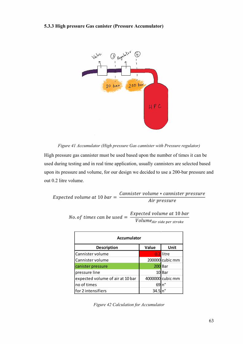
63
5.3.3 High pressure Gas canister (Pressure Accumulator)
Figure 41 Accumulator (High pressure Gas cannister with Pressure regulator)
High pressure gas cannister must be used based upon the number of times it can be
used during testing and in real time application, usually cannisters are selected based
upon its pressure and volume, for our design we decided to use a 200-bar pressure and
out 0.2 litre volume.
𝐸𝑥𝑝𝑒𝑐𝑡𝑒𝑑 𝑣𝑜𝑙𝑢𝑚𝑒 𝑎𝑡 10 𝑏𝑎𝑟 = 𝐶𝑎𝑛𝑛𝑖𝑠𝑡𝑒𝑟 𝑣𝑜𝑙𝑢𝑚𝑒 ∗ 𝑐𝑎𝑛𝑛𝑖𝑠𝑡𝑒𝑟 𝑝𝑟𝑒𝑠𝑠𝑢𝑟𝑒
𝐴𝑖𝑟 𝑝𝑟𝑒𝑠𝑠𝑢𝑟𝑒
𝑁𝑜. 𝑜𝑓 𝑡𝑖𝑚𝑒𝑠 𝑐𝑎𝑛 𝑏𝑒 𝑢𝑠𝑒𝑑 = 𝐸𝑥𝑝𝑒𝑐𝑡𝑒𝑑 𝑣𝑜𝑙𝑢𝑚𝑒 𝑎𝑡 10 𝑏𝑎𝑟
𝑉𝑜𝑙𝑢𝑚𝑒𝐴𝑖𝑟 𝑠𝑖𝑑𝑒 𝑝𝑒𝑟 𝑠𝑡𝑟𝑜𝑘𝑒
Figure 42 Calculation for Accumulator
Description Value Unit
Cannister volume 0.2 litre
Cannister volume 200000 cubic mm
canister pressure 200 Bar
pressure line 10 Bar
expected volume of air at 10 bar 4000000 cubic mm
no of times 69 n°
for 2 intensifiers 34.5 n°
Accumulator
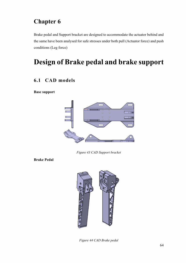
64
Chapter 6
Brake pedal and Support bracket are designed to accommodate the actuator behind and
the same have been analysed for safe stresses under both pull (Actuator force) and push
conditions (Leg force)
Design of Brake pedal and brake support
6.1 CAD models
Base support
Figure 43 CAD Support bracket
Brake Pedal
Figure 44 CAD Brake pedal
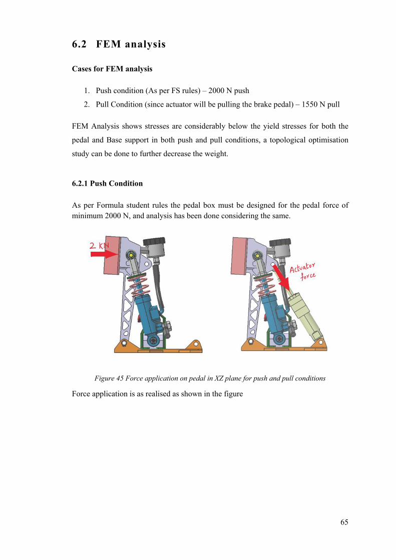
65
6.2 FEM analysis
Cases for FEM analysis
1. Push condition (As per FS rules) – 2000 N push
2. Pull Condition (since actuator will be pulling the brake pedal) – 1550 N pull
FEM Analysis shows stresses are considerably below the yield stresses for both the
pedal and Base support in both push and pull conditions, a topological optimisation
study can be done to further decrease the weight.
6.2.1 Push Condition
As per Formula student rules the pedal box must be designed for the pedal force of minimum 2000 N, and analysis has been done considering the same.
Figure 45 Force application on pedal in XZ plane for push and pull conditions
Force application is as realised as shown in the figure
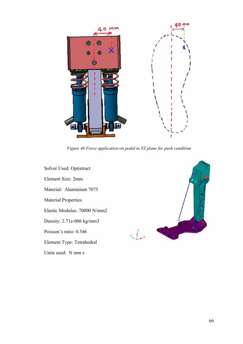
66
Figure 46 Force application on pedal in YZ plane for push condition
Solver Used: Optistruct
Element Size: 2mm
Material: Aluminium 7075
Material Properties
Elastic Modulus: 70000 N/mm2
Density: 2.71e-006 kg/mm3
Poisson’s ratio: 0.346
Element Type: Tetrahedral
Units used: N mm s
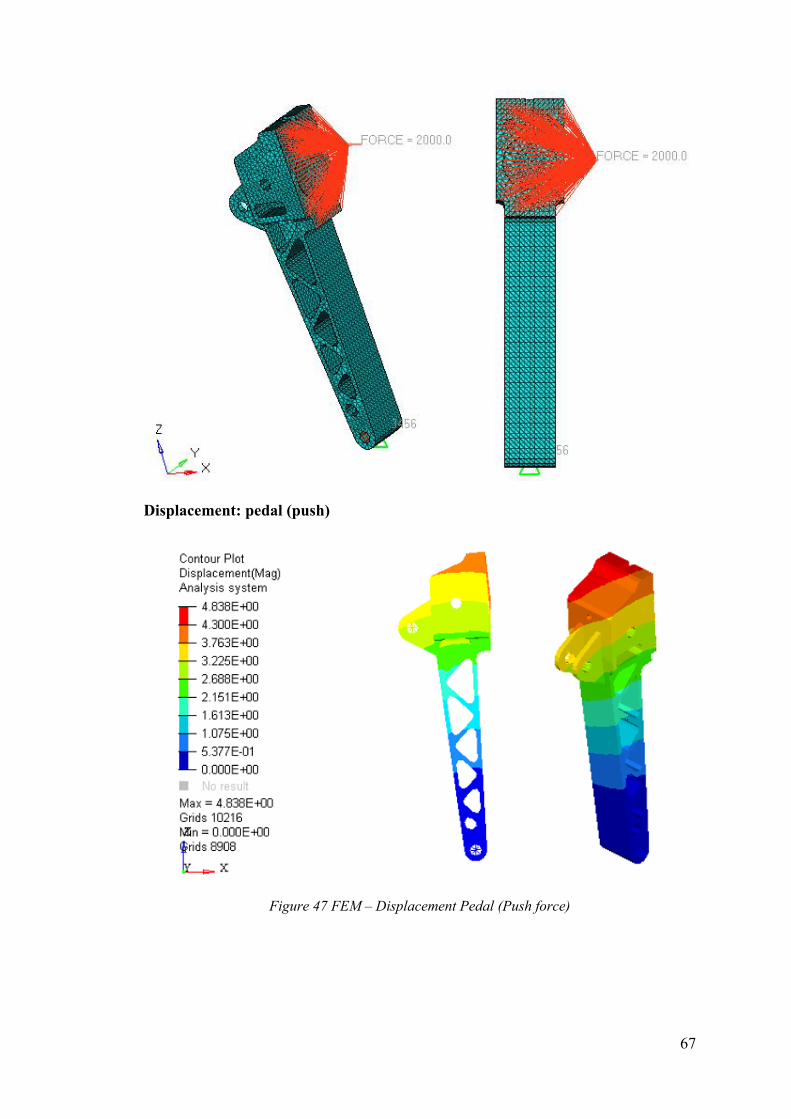
67
Displacement: pedal (push)
Figure 47 FEM – Displacement Pedal (Push force)
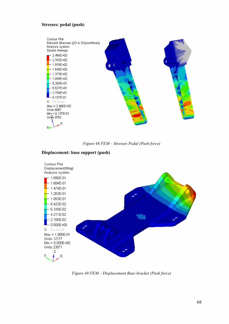
68
Stresses: pedal (push)
Figure 48 FEM – Stresses Pedal (Push force)
Displacement: base support (push)
Figure 49 FEM – Displacement Base bracket (Push force)
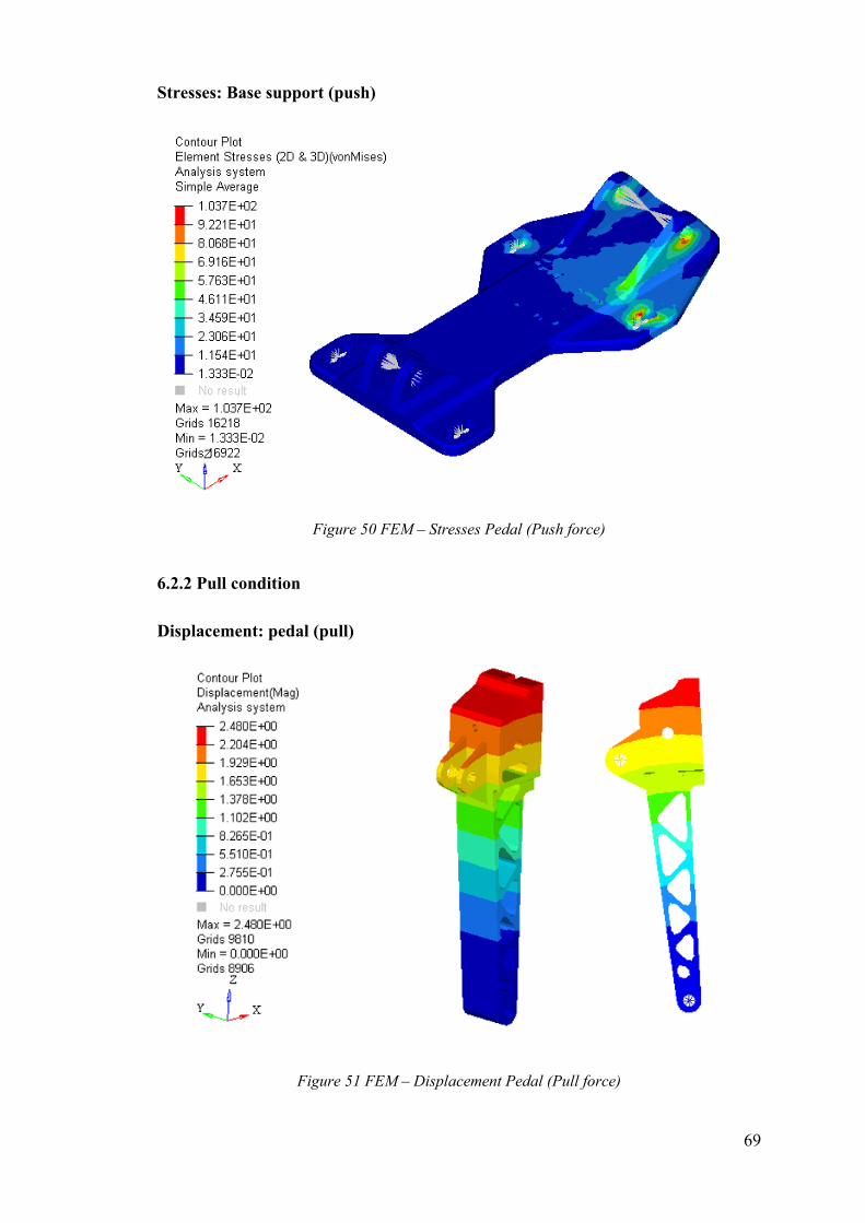
69
Stresses: Base support (push)
Figure 50 FEM – Stresses Pedal (Push force)
6.2.2 Pull condition
Displacement: pedal (pull)
Figure 51 FEM – Displacement Pedal (Pull force)
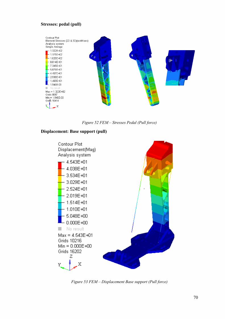
70
Stresses: pedal (pull)
Figure 52 FEM – Stresses Pedal (Pull force)
Displacement: Base support (pull)
Figure 53 FEM – Displacement Base support (Pull force)
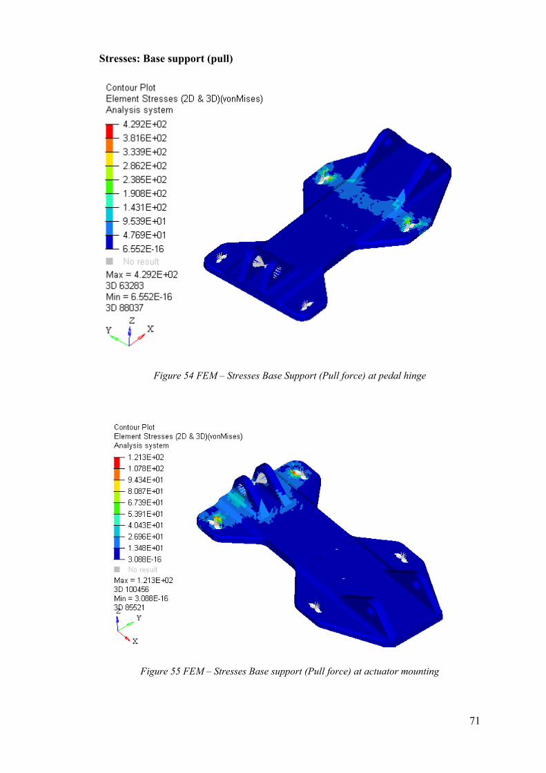
71
Stresses: Base support (pull)
Figure 54 FEM – Stresses Base Support (Pull force) at pedal hinge
Figure 55 FEM – Stresses Base support (Pull force) at actuator mounting
72
Conclusion
From this thesis, a functional design solution for EBS has been developed and the
feasibility analysis for its proper functioning has been performed. Most of all the
important criteria of having a fail-safe EBS operation has also been developed by
incorporating an algorithm which uses a redundant secondary system in the event of
primary system failure.
As per FSG 2020 regulations, the EBS must be a passive system and it is optional to
use the service brakes for EBS. Since there exists a hydraulic brake system in the car
already and will not be used for primary braking in the developed Driverless car, we
have incorporated it as part of our EBS. This has made the overall system less complex
and with lesser components considering the space inside the cockpit is very limited.
The pedal box used is from last year’s FS car and it was chosen based on its simple
design and smaller X-direction encumbrance suiting the likes of the cockpit space
availability in adding the EBS components. As a way forward, the design prototype
will be fabricated and installed in the car for testing and evaluation of the EBS
performance. The results obtained will be analysed for compliance to the requirements
and improvised accordingly. Further topological optimisations can be performed on the
pedal box to make it simpler and more compatible for EBS operation as well as in
minimising the overall weight of the system.
The car which shall be developed for the next FSD competition can be designed based
on the constraints faced in the current development of EBS for SC19. This gives an
opportunity to develop a better and less complex EBS solution for the driverless car.
73
Bibliography
[1] G. Genta, Motor Vehicle Design.
[2] Formula Student 2020 Rulebook, [Online]. Available:
https://www.formulastudent.de/fileadmin/user_upload/all/2020/rules/FS-
Rules_2020_V1.0.pdf.
[3] D. R. K. Bansal, A textbook of Fluid Mechanics.
[4] Pierce, Alia, “Formula Student Germany 2019 Magazine,” 2018. [Online].
Available:
https://www.formulastudent.de/fileadmin/user_upload/all/2019/PR_Media/FSG2
019%20magazine%20v20190724_LQ.pdf.
[5] E. Zurich, “AMZ Driverless: The Full Autonomous Racing System”.


