
1
HYBRID SOLAR/ HEAT PIPE/ WATER HEATER
LAU JIN YIK
A project report submitted in partial fulfilment of the
requirements for the award of the degree of
Bachelor of Engineering (Hons) Industrial Engineering
Faculty of Engineering and Green Technology
Universiti Tunku Abdul Rahman
May 2015

ii
DECLARATION
I hereby declare that this project report is based on my original work except for citations
and quotations which have been duly acknowledged. I also declare that it has not been
previously and concurrently submitted for any other degree or award at UTAR or other
institutions.
Signature : _________________________
Name : _________________________
ID No. : _________________________
Date : _________________________
iii
APPROVAL FOR SUBMISSION
I certify that this project report entitled “HYBRID SOLAR/HEAT PIPE/ WATER
HEATER” was prepared by LAU JIN YIK has met the required standard for
submission in partial fulfilments of the requirements for the award of Bachelor of
Engineering (Hons) Industrial Engineering at Universiti Tunku Abdul Rahman.
Approved by,
Signature : _________________________
Supervisor : Prof. Ir. Dr. Ong Kok Seng
Date : _________________________

iv
The copyright of this report belongs to the author under the terms of the
copyright Act 1987 as qualified by Intellectual Property Policy of Universiti Tunku
Abdul Rahman. Due acknowledgement shall always be made of the use of any material
contained in, or derived from, this report.
© 2015, Lau Jin Yik. All right reserved.

v
Specially dedicated to
My beloved mother and father

vi
ACKNOWLEDGEMENTS
First of all, I would like to thank to everyone who gave me the opportunity and to
complete my task successful. A heartfelt gratitude goes to my final year project
supervisor Prof. Ir. Dr. Ong Kok Seng, for his supervision, tolerance, inspiration, and
support. His direction and helpful proposals through this our project has contributed to
my achievement of this project.
Secondly, I would like to express gratitude to Mr. Lee Jie Sheng for thoughtful
discussions we shared of this project gave me a lot of suggestions throughout the
experiments. My sincere thanks also goes to my coursemates especially Mr. Chong Wei
Kiet and Mr. Lee Kok Hoong who helped me a lot my experimental project, and for all
the fun we had in four years of my degree life.
My thankfulness additionally goes to the laboratory staffs, Encik Khairul Hafiz
and Encik Mohd Syahrul, who gave me the permission to utilize all the required tools
and instruments in the investigation.
Lastly, I would like to thank to my family. Without their unwavering love and
support, I would not be where I am today. Thank you for all sacrifices and
encouragement during my studies.

vii
HYBRID SOLAR/ HEAT PIPE/ WATER HEATER
ABSTRACT
The performance of a hybrid solar/ heat pipe/ water heater were investigated the system
conversion of an array individual evacuated tube heat pipe solar collector (ETHPSC)
exposed to sunlight, four thermoelectric (TE) modules are placed on the outer surfaces
of the aluminum block and four units of water cooled jackets are placed over the TE
modules. The jackets are thin aluminum composite slabs with parallel internal water
flow channels connected by inlet and outlet headers inside the slabs. The experiment
result showed that water can be heated with a temperature difference of around 0.3 oC –
7.6 oC.
viii
TABLE OF CONTENTS
DECLARATION ii
APPROVAL FOR SUBMISSION iii
ACKNOWLEDGEMENTS vi
ABSTRACT vii
TABLE OF CONTENTS viii
LIST OF TABLES x
LIST OF FIGURES xi
LIST OF SYMBOLS / ABBREVIATIONS xiv
CHAPTER
1 INTRODUCTION 1
1.1 Background 1
1.1.1 Solar energy 1
1.1.2 Heat pipe 3
1.2 Problem statements 5
1.3 Aims and Objectives 5
1.4 Outline of Report 6
2 LITERATURE REVIEW 7
3 THEORITICAL INVESTIGATION 18
ix
3.1 Theoretical calculation 18
4 EXPERIMENTAL INVESTIGATION 20
4.1 Experimental Apparatus 21
4.2 Experimental Procedures 28
4.3 Experimental Results 32
5 DISSUSION OF RESULTS 49
6 SUGGESTION FOR FUTURE STUDIES 53
7 CONCLUSIONS 54
REFERENCES 55
APPENDICES 56

x
LIST OF TABLES
TABLE TITILE PAGE
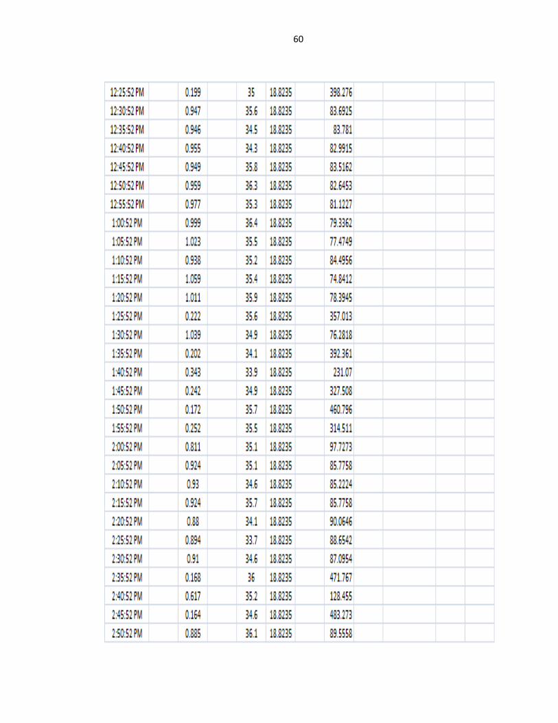
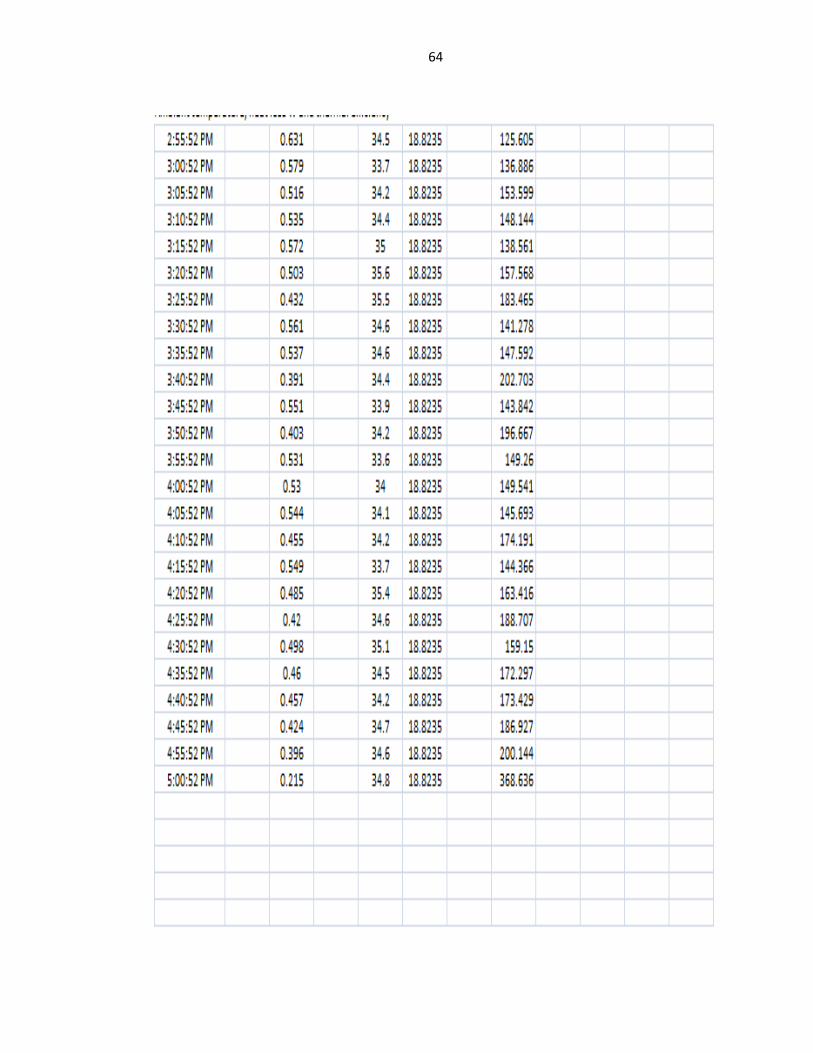
Table 1 Raw data for run 1 (0.9g/s) 59
Table 2 Raw data for run 2 (1.5g/s) 62
Table 3 Raw data for run 3 (8.33g/s) 65
Table 4 Raw data for run 4 (0.9g/s) 68

xi
LIST OF FIGURES
FIGURE TITLE PAGE
Figure 1 Schematic of the condenser and evaporator section of a heat pipe 4
Figure 2 Thermal and electrical efficiencies vary with water temperature 10
Figure 3 Schematic Diagram of Experimental Setup 21
Figure 4 a) Exploration view 22
b) Assembly view 22
Figure 5 a) aluminum block 24
b) Water cooling jacket 24
Figure 6 Photograph of installation heat pipe with metal frame 25
Figure 7 Photograph of installation water input pipes together with 26
Thermocouple
Figure 8 Photograph of installation cover 27
Figure 9 Flow of heat energy in a solar water heater and Flow of energy 29
in the solar / heat pipe / TE hybrid system
Figure 10 Temperature points on TEG system. 30
Figure 11 Temperature points on evacuated tube solar water heating system 31
Figure12 Typical experimental results showing solar radiation, ambient 33
temperature (coolant flow rate = 0.9 g/s)(run 1)
xii
Figure 13 Typical experimental results showing solar radiation, ambient 34
temperature (coolant flow rate = 1.5 g/s)(run 2)
Figure 14 Typical experimental results showing solar radiation, ambient 35
temperature (coolant flow rate = 8.33 g/s)(run 3)
Figure 15 Typical experimental results showing solar radiation, ambient 36
temperature (coolant flow rate = 0.9 g/s)(run 4)
Figure 16 Typical experimental results showing heat pipe and condensor 37
temperature (coolent flow rate = 0.9)(run 1)
Figure 17 Typical experimental results showing heat pipe and condensor 38
temperature (coolent flow rate = 1.5)(run 2)
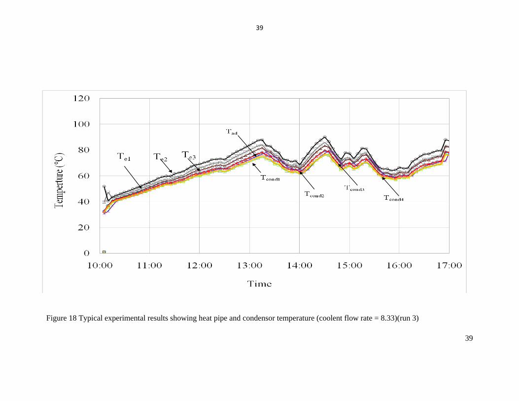
Figure 18 Typical experimental results showing heat pipe and condensor 39
temperature (coolent flow rate = 8.33)(run 3)
Figure 19 Typical experimental results showing heat pipe and condensor 40
temperature (coolent flow rate = 0.9)(run 4)
Figure 20 Typical experimental results showing TE hot side and cold side 41
temperature (coolent flow rate = 0.9 g/s)(run 1)
Figure 21 Typical experimental results showing TE hot side and cold side 42
temperature (coolent flow rate = 1.5 g/s)(run 2)
Figure 22 Typical experimental results showing TE hot side and cold side 43
temperature (coolent flow rate = 8.33 g/s)(run 3)
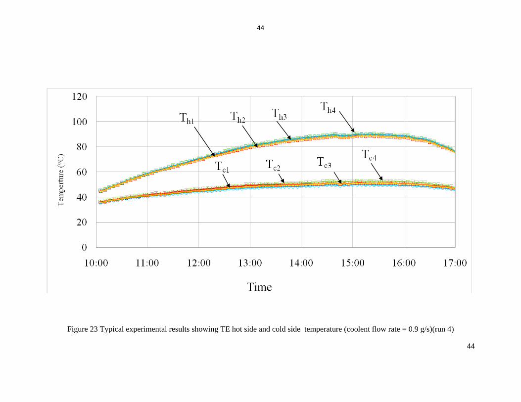
Figure 23 Typical experimental results showing TE hot side and cold side 44
temperature (coolent flow rate = 0.9 g/s)(run 4)
Figure 24 Typical experimental results showing thermal efficiency and 45
water input and output temperature (coolent flow rate = 0.9 g/s)(run 1)
Figure 25 Typical experimental results showing thermal efficiency and 46
water input and output temperature (coolent flow rate = 1.5 g/s)(run 2)

xiii
Figure 26 Typical experimental results showing thermal efficiency and 47
water input and output temperature (coolent flow rate = 8.33 g/s)(run 3)
Figure 27 Typical experimental results showing thermal efficiency and 48
water input and output temperature (coolent flow rate = 0.9 g/s)(run 4)

xiv
LIST OF SYMBOLS
q heat removal rate, W
ηw thermal efficiency %
Cpw specific heat capacity of water, J/kg.K
T temperature, oC
ΔT temperature difference
Ta ambient temperature, oC
Te1 – Te3 temperature points on heat pipe evacuated tube, oC
Tadb temperature points on heat adiabatic, oC
Tatm temperature pints on atmosphere, oC
Tcond1- Tcond4 temperature points on condenser, oC
Tal1- Tal12 temperature points on aluminum block, oC
Ths1 – Ths12 temperature points on heat sink, oC
H solar radiation, oC
Twi water inlet temperature, oC
Two water outlet temperature, KW/m2
Th1 – Th4 TE hot side temperatures, oC
Tc1 – Tc4 TE cold side temperatures, oC
Asc area of evaporator,m2
1
Chapter 1
Introduction
1.1 Background
1.1.1 Solar energy
Nowadays, with the reducing of fossil fuels consisting of petroleum, coal, natural
gas and heavy crude oil, which contribute about ¾ of all carbon, methane, nitrogen
oxide and other greenhouse gases emission into atmosphere when fossil fuel use to
generate energy from combustion. The effect of those sources will lead to climax change,
environmental pollution and acid rain known as global warming. Greenhouse gases is
trapping the heat from sun to keep our earth suitable for living, however, when the
greenhouse gases too many may cause our earth temperature rises rapidly and out of
control would be issue as global warming.
Therefore, much effort has been directed to finding a new renewable energy
source and developing green technologies to reduce dependency on fossil fuel

2
combustion environment issues. Solar energy consider as sustainability without affect
ecosystem and this kind of renewable energy generally comes from the directly exposed
to sunlight. In addition, solar energy has been started to adopt as renewable energy
because it is the sources without compromising the future generation and unlike
nonrenewable energy such as fossil fuel can release many hazardous gases to
atmosphere and unlimited. Other than that, Solar energy can be consider as green
environment friendly, because it release low carbon to atmosphere also widely use on
today. Solar energy can be converted into useful energy in various technologies such as
transfer solar energy into heat energy implement by solar water heater and photovoltaic
system transfer solar energy to electric energy.
The solar energy is the ultimate sources to provide solar radiation that can be
changed over into energy specifically utilizing different advances for some techniques to
harness the solar thermal and solar photovoltaic energy. In such cases, the efficient heat
transfer device is concerns of energy utilization and environmental pollution work on
clean energy simultaneously. Therefore, usage of solar energy brought to accomplish a
safe and comfortable environment for sustainable of human life. Solar energy has been
development of renewable energy because it can be replenish the sources continuously
on specific natural process also very valuable to develop in Malaysia because located on
equator. Solar energy can be changed over into helpful in different innovation, for
example, transfer solar energy into heat energy implement by solar water heater and
photovoltaic system transfer solar energy to electric energy.
Solar energy has proven to be a viable source of renewable energy for water
heating system. The review indicated that the application of heat pipe system can
significantly increase heat transfer rates thus increase the thermal efficiency.
Furthermore, the idea of heat pipe is that solar energy will be collected by solar tube
collector when exposed to sunlight and transferred to the evaporator section of the heat
pipe inside the solar tube collector. The energy absorbed then is used for thermal heating
3
application such as water heating in order to prevent any waste energy from occurring
thus increasing the overall performance of the system.
1.1.2 Heat pipes
In the recent past decades, research aimed at the development of thermal
absorption has intensified to increase the efficiency or performance solar system.
However, the efficiency of power source can be improved with help of heat pipes heat
exchanges. Heat pipe performed as utilizing the evaporation and condensation heat
transfer process while the solar energy as a heat source obtained from exposure to
sunlight. The heat pipe was first invented by Angier March Perkins in 1839 which the
time he called it as hermetic boiler tube. In 1963, George Grover and his co-workers
further created the prototype and named it as heat pipe then widely apply in industries.
The first heat pipe application was in satellites to accomplish the thermal equilibrium
between side presented to the sun's radiation and the other presented to the deep cool
space.
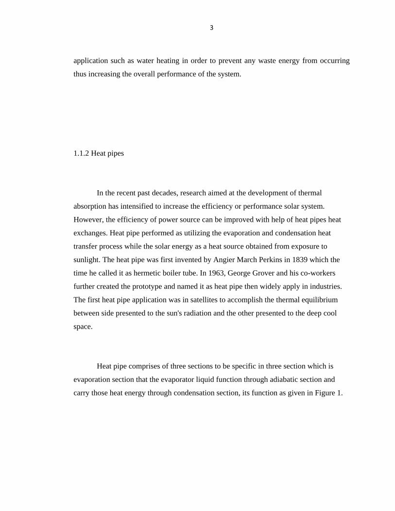
Heat pipe comprises of three sections to be specific in three section which is
evaporation section that the evaporator liquid function through adiabatic section and
carry those heat energy through condensation section, its function as given in Figure 1.

4
Figure 1: Schematic of the condenser and evaporator section of a heat pipe.
The concept of heat pipe is based on working fluid absorbing amount of heat
energy thus turns into evaporation of vapor. The vapor flow into inverse end of the
condenser zone where it loses its heat to cold interface will be condensates into liquid.
Liquid flow back to the evaporation zone and the principle of both processes of cycle
repeats.
Heat pipe device is perform heat transfer in very high performance also large
quantity of heat effectively and efficiently by utilizing the evaporation and condensation
heat transfer process. Meanwhile, there are many investigation about heat pipe thus to
determine by variety operational parameter such as select the pipe material. Material that
generally used to construct a heat pipe would be nickel, aluminum, copper and stainless
steel. Beside on that, other investigation of working fluid at certain temperature ranges
by measure surface of heat flux. Many research has been indicate the liquid ammonia
heat pipe are favorite be used in industrial because it is lightweight. However,
experiments show that condition of water heat pipe has most effective combine with
copper vessels for generate temperature range between 5 to 230 oC.

5
1.2 Problem statements
Thermal performance characteristics of Hybrid solar/heat pipe/ water heating system are
to find out a solution to improve the reliability operation. As there are many
configurations could be applied on this performance characteristics and relationships
would prove a great step towards the development of viable environmental friendly
heating application. Therefore, in this study will concentrate about heat transfer from
both side of TE module to provide thermal heating efficiently as well as prevent any
waste heat from occurring thus increasing the overall efficiency of the system. This is an
attractive saving system would be developed and studied in this research.
1.3 Aims and objective
The studied was carried out investigation the thermal performance characteristics
of a hybrid solar heat pipe collector coupled to a thermoelectric module and water
cooled jacket for hot water production.

6
1.4 Outline of report
Chapter 1 presents the background of solar energy as renewable energy and heat
pipe heat exchanger. This chapter likewise discuss about the problem statement and
objective of this research. A chapter 2 talk about the writing literature review from
explores that with respect to this research which is regarding of characteristics of a
hybrid solar heat pipe. Methodologies and discoveries from the analysts will be talked
about in this section. Chapter 3 describes depicts about hypothetical model of Hybrid
solar/heat pipe/water heater. Some theoretical calculation about heat transfer rate and
thermal efficiency for this experiment will be examined in this section. In Chapter 4 will
explain about experimental apparatus consists on Hybrid solar/heat pipe/ water heater
also the experimental setup on this system. Other than that, this part additionally talks
about the results finding for this experimental research. Results will be plot out to
indicate various performance conditions without further explanation. Chapter 5 will
continuous explain about the test results for each runs also some comparison of
consequences of the impact of performance of project that will be discuss. Other than
that, this part additionally talks about the impact of thermal efficiency performance.
Chapter 6 has provided some of the recommendation for future studies and methods
required for future examination. Chapter 7 discuss the finish of this undertaking and
some discoveries on performance of hybrid solar/ heat pipe/ water heater will be
determined

7
Chapter 2
Literature review
2.1 Application and performance of heat pipe
Yan, et al. [1] experimentally investigated the affecting elements of heat transfer
exchange using of Heat pipe heat exchanger and he demonstrated the several factors
which will lead to performances like distance across of heat pipe which is heat carry
through the evaporator process located at length of heat pipe. Next the heat pipe consists
of aluminum heat fin which heat up the working liquid inside the heat pipe spacing have
an unprecedented lead on the heat exchange process and will affected pressure drop. In
this study, The choice of fin he suggested is the thickness as small as possible to ensure
the heat energy balance transfer more effectively and efficiently

8
2.2 Hybrid solar heat pipe thermoelectric modules heat generation.
Chen, Wei-Hsin et al. [2] conducted a research of characteristic of TEM at
different operating condition by investigates the power and heat generated
simultaneously by low temperature heat exposure sunlight. He suggested that 0.4 L/min
water flow rate has been use for this experiment research also TE modules place along
surface of condenser to analysis the thermal performance. Results have indicated the
growing of TE heat and power performance relay to raising heat source. However, the
efficient for system was found the efficiency has about linear dependence on the
temperature different.
Date, Ashwin et al. [3] presented experimental on the behavior of a proposed
combined solar water heating application together with power generation of
thermoelectric system. They proposed construction comprises of concentrated solar
collector thermal device that gives a high thermal flux source for thermoelectric
generators. An experimental investigated a flux of 50,000 W/m2 a temperature
difference of 75 C across the thermoelectric generator can be achieved and 80 C of hot
water was heated up through this experiment. This might helpful be used for domestic or
industrial applications. According to this experiment has show that 3.02 V of open
circuit voltage can be generated for each thermoelectric generator with dimensions of 40
mm 40 mm.
He et al [4] conducted a trial study on heat pipe solar collectors combine with the
fuse of TE module. This hybrid can be utilized for joined water heating and electrical
power generation, this model configuration comprises of a TE module combining
between the condenser of the heat pipe and a water channel. Solar energy is received
will converted through the heat pipe to provide the TE module while the water channel
absorbs heat from the other end of the module thus creating a temperature different

9
required for power generation. An analytical model was displayed to find out the
average performance of thermal and electrical simultaneously with the ambient
temperature. Beside on that, solar irradiation and water temperature also become a
reference in this experiment together with other geometrical specification of the system.
This simulation demonstrated that 45 degree of water temperature and 600W/m2 solar
radiation has results a thermal efficiency of 55 percent and electrical of 1 percent. This
experiment also compared the electrical efficiency to that of an organic rankine cycle
with 3 until 4 percent efficiency. Although this system has an electrical efficiency of 1-2
percent but the design and non-existing move components make the application more
accessible and applicable.
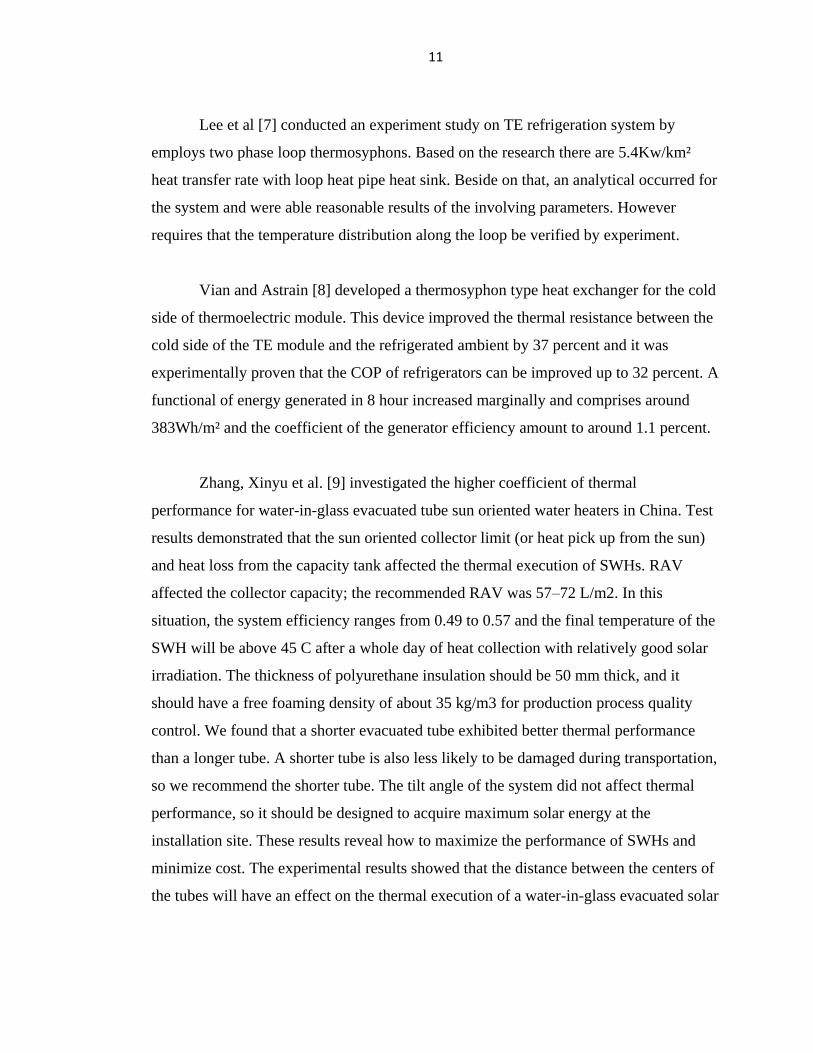
Figure 2 shows the result of thermal effectiveness and electrical proficiency for
diverse solar irradiation. Experimental shows increase of solar irradiation influence the
performance of the SHP-TE unit increment and both thermal productivity and electrical
effectiveness decrease with expanding water temperature. Based on figure below shows
that there is about 25 percent of thermal energy has been reducing within TE this is
change into electrical power. Meanwhile, the increasing the number of thermo element
lead the better performance of thermal efficiency because it will increase heat conduct
through the thermoelectric module.

10
Figure2: Thermal and electrical efficiencies vary with water temperature.
Zhang, Ming et al. [5] outlined a solar thermoelectric co-generator (STECG),
which can created electrical power and heat energy simultaneously, he setup a system
whereby consists of evacuated heat pipe and TE modules . It consists of an array of 36
evacuated tube heat pipe solar collectors with resistances energy of 1.24 K/W per TEM
and a module ZTM of about 0.59. The STECG successfully warm up water as it
experienced the heat pipes and normal evaporator tube gatherer capability was
46.72%can be created 0.19 kW h of electrical power and around 300L of heated water at
temperature from 25 C to 55 C in a day.
Gang, Pei et al. [6] investigated a system of heat pipe thermal systems utilizing a
piece of aluminum plate. First, he was started with the constant flow rate of 0.1kg/s, four
units of water cooled jackets are placed over the TE modules and each of the water flow
rate was 0.025 kg/s. The decrease in the valuable thermal energy fluctuates somewhere
around 23% and 38%, which of the electrical energy shifts somewhere around 1.5% and
4.3%.
11
Lee et al [7] conducted an experiment study on TE refrigeration system by
employs two phase loop thermosyphons. Based on the research there are 5.4Kw/km²
heat transfer rate with loop heat pipe heat sink. Beside on that, an analytical occurred for
the system and were able reasonable results of the involving parameters. However
requires that the temperature distribution along the loop be verified by experiment.
Vian and Astrain [8] developed a thermosyphon type heat exchanger for the cold
side of thermoelectric module. This device improved the thermal resistance between the
cold side of the TE module and the refrigerated ambient by 37 percent and it was
experimentally proven that the COP of refrigerators can be improved up to 32 percent. A
functional of energy generated in 8 hour increased marginally and comprises around
383Wh/m² and the coefficient of the generator efficiency amount to around 1.1 percent.
Zhang, Xinyu et al. [9] investigated the higher coefficient of thermal
performance for water-in-glass evacuated tube sun oriented water heaters in China. Test
results demonstrated that the sun oriented collector limit (or heat pick up from the sun)
and heat loss from the capacity tank affected the thermal execution of SWHs. RAV
affected the collector capacity; the recommended RAV was 57–72 L/m2. In this
situation, the system efficiency ranges from 0.49 to 0.57 and the final temperature of the
SWH will be above 45 C after a whole day of heat collection with relatively good solar
irradiation. The thickness of polyurethane insulation should be 50 mm thick, and it
should have a free foaming density of about 35 kg/m3 for production process quality
control. We found that a shorter evacuated tube exhibited better thermal performance
than a longer tube. A shorter tube is also less likely to be damaged during transportation,
so we recommend the shorter tube. The tilt angle of the system did not affect thermal
performance, so it should be designed to acquire maximum solar energy at the
installation site. These results reveal how to maximize the performance of SWHs and
minimize cost. The experimental results showed that the distance between the centers of
the tubes will have an effect on the thermal execution of a water-in-glass evacuated solar

12
water heater without diffuse reflectors, and the external distance across of the evacuated
tube is another factor, both of which need further research.
Liu, Zhen-Hua et al. [10] studied a novel evacuated tubular solar air incorporated
with simplified CPC and open thermosyphon. This system was designed to provide air
temperature for utilize the water based CuO nano liquid as working fluid. This
experimental apparatus used in the system which is consists of two link panel whereby
each panel consists of one evacuated tube. Meanwhile it is also consist of a simplified
CPC together with open thermosyphon. The comparison of examination includes air
outlet temperature of the system whereby the system total effectiveness has been
investigated. Likewise, there are two different experimental system was done by
investigated both performances. The experiment study the influences of different
structure show that thermosyphone is better than collector with concentric tube. Further
result also show that nanofluids have better performances working with thermosyphone.
Wei He et al [11] exhibited a test study on parametrical examination of the
outline and execution of a solar heat pipe thermoelectric generator unit. The analysis
was compared the complex influence with different solar irradiation, ambient
temperature, water temperature and other geometrical specifications of the system. This
analysis is presented based on different characteristics performance and ideal
configuration parameters contrasted and the state of a consistent temperature. The
simulation indicated that peak point of three most extreme force transformation
effectiveness is 3.346 percent when solar irradiation was 1000Wm2.
Sateikis et al [12] carried out investigation of a micro-power TE generator
operating at a low temperature different. This experiment was studied energy evaluation
of the TE generator utilizing two lines of three TE modules associated in between water
flows in a counter-flow arrangement which is connected in series. Next, the
experimental result show amount of the energy generated in 8 hours increased

13
marginally when the comparative cold water flow rate was 0.347-0.376 liter per second
and the coefficient of the generator efficiency amount to around 1.1 percent.
Gaowei Liang et al [13] presented the performance of a parallel TE generator by
hypothetical investigation and experimental result. Based on the theoretical model was
takes into account for example heat sink, temperature of heat source, contact resistance
and thermal contact resistance of every TE module in parallel and an exploratory system
was then constructed to confirm the theoretic model. Results demonstrate that just when
all TE modules have the same inalienable parameter and working conditions, the parallel
properties imitate that of a common DC power source. It was additionally demonstrated
that increment in thermal contact resistance act simply like an increment of the TE
module's interior resistance which prompt diminishing to decrease in power generated.
The analytical result derived was consistent with the experimental results despite some
discrepancies due to assumptions made to ignore heat conduction between thermocouple.
Khattab et al [14] studied the ideal operation of thermoelectric cooler driven by
solar thermoelectric generator. This experiment included the theory of both TE
generation and TE cooling as well as the requirements for the TE cooling system to
achieve best performance from the TE power generator all year around. Performance
tests was led to focus both the physical properties and the execution bends of the
accessible TE modules and a theoretical model was developed to simulate the TEG-TEC
system to anticipate its execution throughout the entire year under specific climate
conditions. The results indicated that due to low conversion efficiencies of the TEG
system, 10 TE power generator modules were obliged to control the TEC at ideal
execution at most times of the year. Despite the required number of TE modules needed
to power a TE cooling system, this indicated that solar power generation is able to
provide electrical power reliably throughout the year.

14
Chavez et al [15] investigated the possibility of using thermoelectric generators
in solar hybrid systems. This experiment was examined for those four systems which is
one of the traditional photovoltaic thermal geometries with TE modules allocated
between solar cells and the heat extractor, working without radiation concentration, and
other three was using concentrators in various set up. The efficiency for each system was
investigated and it was found that the TEG efficiency has almost linear dependence on
the temperature different between junctions, reaching about 4 percent at a temperature
different of 155 degree and indicated that regardless of the setup, TEG works as long as
a constant temperature difference can be supplied. Therefore, the addition of a TEG
generator to a photovoltaic solar cell will allow an increase in electrical power generated
by the system. However the low conversion efficiency of about 5 percent are still not a
reliable and viable power generator.
Lertsatitthanakorn et al [16] performed a hybrid thermoelectric solar air collector
which generates both thermal and electric power generation simultaneously. This
experiment has double-pass TE solar air collector and developed where the occurrence
solar radiation warms up a heat absorber plate so that a temperature contrasts made
between the TE modules. Results demonstrate that the warm proficiency increments as
the air flow rate increase at the point when the surrounding wind current through the
warmth sink situated at the lower channel to pick up heat while cooling the TE modules
hence provide heat to the air flow. Other than that, the electrical proficiency rely on
upon the temperature difference obtained and this experiment results at a temperature
different was 22.8 degree, the system was generated 2.13W of power output and the
change productivity of 6.17 percent. This concept of solar collector concept for supplied
heat source has widely anticipated increasing the output of TE power generate system
due to its abundance.
Rahbar et al [17] also studied of a novel portable solar still by still by using the
heat pipe and thermoelectric modules. This design function while water is evaporated

15
due to exposure to solar energy and condensed by the cooling provided by a TE modules
act as a heat-pump. Heat is then rejected at the other end of thermoelectric modules
using a fan and a heat pipe system. The experiment results indicated that the surrounding
temperature and sun based radiation have an immediate impact on the framework
execution however there is a lessening in water profitability by increase the wind speed.
This study display of the efficiency and applicability of incorporated heat pipe
technology and solar energy into the function of thermoelectricity and the application
was flexible of TE modules and heat pipes work well together to provide a stable TE
system.
Maneewan et al [18] constructed and carried out a lab-scaled investigation on the
generating power of thermoelectric roof solar collector. The design consists of a
straightforward acrylic sheet and air hole. Next, this experiment also employs a copper
plate in other to absorb heat with combination to thermoelectric modules and a
rectangular balance heat sink. The halogen lamp also employ for generate the solar
radiation energy thus to heat up somewhere around 400 and 1000W/m2. Solar radiation
will expose carrier the heat energy to the copper plate so that create temperature
different in between TE modules in that way to convert the heat energy. The cooling
system of fan was used by current power generated along the experiment. Ten TE
modules were used in this design and it was found that the system could generated
around 1.2W under sun based radiation power of 800W/m2 at a surrounding temperature
shift between 30 degree and 35 degree. Despite the innovation design and demonstration
of the flexibility of TE modules, the system was possesses a low electrical conversion
efficient of 1-4 percent.
Miljkovic et al [19] were displayed and improvement of a hybrid solar
thermoelectric system which utilizes a thermosyphon as a method of heat transfer to
convey warmth to a base cycle for different applications. An illustrative trough
concentrates sunlight based energy onto a specific surface coated thermoelectric
modules as the hot junction while a thermosyphon adjoining to the back side of the
16
thermoelectric device which keeps up the temperature of the cold junction thus
producing electric power. An energy-based model of the system with a thermal
resistance network system was produced to focus the overall performance of the system.
In addition, the system proficiency for temperature of 300 until 1200 liter, solar
centralizations of 1-100 aggregates, and diverse thermosyphon and thermoelectric
materials were investigated and the geometry of the thermosyphon was also investigated.
Result show the optimization of the system that the efficiency as high as 52.8 percent
can be accomplished at ideal detail. The solar concentration convergences of 100 suns
and a base cycle temperature of 776K result obtained that TE system can be used at
higher temperatures while keep up the electrical change efficiencies this is unlike the
conversion efficiencies of photovoltaic technologies which starts to deteriorate as the
mean working temperature increases. This simulated level of solar irradiation is far on
the high side and will be hard to obtain in reality. However this indicated the potential of
a solar generator.
Zhang et al [20] outlined a sun powered thermoelectric and hot generator which
can heat as well as electrical power generation simultaneously, within thermoelectric
module to the heat pipe in an evacuated tube solar collector. A ring shaped TE module is
applied around the condenser of the heat pipes was sandwich which was combine in
between heat spreader and heat sink . A theoretical model for accurately prediction the
thermal losses based on energy balance and heat exchange mathematical statement was
figure out and based on the theoretical model for TE modules can produce an electrical
efficiency of 1.59 percent when solar irradiation is 1000W/m2, wind velocity is 1.3 m/s,
ambient temperature and water temperature of 25 degree. This shows that the TE
modules incorporated evacuated tube solar collectors are economical and practical.

17
Chapter 3
Theoretical calculation
3.1 water heating
The heat energy absorbed by the water channel will be used to heat up the water in the
water tank of this experiment. Heat transfer to the water tank is measured by the change
in temperature and can be determine by equation below.
. .
( )w pw wo wiwq m c T T (1)
Where the
qw = heat transfer rate w
mw= mass of object heated g/s
Cpw = specific heat capacity for water is 4.183 J/g °C
△T= changing in temperature △T= T2- T1 T

18
The total instantaneous thermal efficiency of the hybrid water heater is determined from
.
4100 %
( )
ww
SC
qx
H A
(2)
Whereby
qw = heat transfer rate w
H= solar radiation Kw/m²
Asc= area of evaporator m²

19
Chapter 4
Experimental investigation
An experimental SHPTE hybrid system with a single ETHPSC was set-up as
shown in Figure 3 which is solid work diagram show the framework was setup. Major
dimensions are listed in figure 5 and. Isometric views of the aluminum block and water
cooling jacket are shown in Figure 4 (b). The aluminum block measured 70 x 105 mm
with a 24 mm diameter hole bored into it to fit over the condenser of the heat pipe. Each
cooling jacket measured 0.04m x 0.04m x 0.02 mm thick with six 2 mm diameter
channels machined inside and connected to two 5 mm diameter common manifolds for
water flow into and out of the jacket. Water mass flow rate is assumed equal in all the
water channels in the jackets. The ETHPSC was inclined at about 30 degrees to the
horizontal. Solar radiation was measured utilizing a Kipp and Zonen solarimeter which
is place at flat surface 0 degree. Coolant water mass flow rates supplied from an
overhead cold water supply tank were adjusted to produce roughly equal flow rates to
each jacket. Type T copper-constantan thermocouples were employed to measure the
temperatures at the locations shown in Fig. 7. Resistance loads to the TE modules were
applied using common resistors of about 5.3 ohms each. Solar radiation, temperatures
and TE voltages were recorded on a data logger at 1 minute‟s intervals

20
4.1 Experimental Apparatus
Figure 3 demonstrate a schematic graph of hybrid solar/ heat pipe/ water heater
system experimental setup. Based on this experimental setup comprises of the part
including a hybrid heat pipe solar collector, an aluminum condenser, four piece of
thermoelectric modules and four water cooled jacket was used in this experiment study.
The configuration and development of the framework are portrayed the assessment of its
execution by combination of theoretical modeling and experimental testing. Heat energy
presented to daylight and heat transfer to the evaporator section of the heat pipe which
would transfer heat to water supply as creating a temperature different to generate power
and heat simultaneously.
Figure3: Schematic Diagram of Experimental Setup

21
a) Exploration view b) Assembly view
Figure 4: a) Exploration view and b) Assembly view combine with aluminum
block, water jacket and TE modules.
The solid work of system was presented as figure 4 shown the exploration view in
section (a) used in this experiment. The cooled jacket, TEs, cock board and aluminum
block acts as thermal loading as that the condenser across to provide thermal
conductivity along the process. Section (b) was the combination of those apparatus
applied between aluminum block surface and aluminum water jacket.
Thermocouple Calibration
The thermocouple wire used in this experiment is type T thermocouple that can operate
at temperature range between -250 oC to 350
oC. Thermocouples were exact to inside
±0.5oC. 45 thermocouples were utilized as a part of this venture. There are some
hardware and device used to adjust thermocouples. The equipments was used in this
experiment is stopwatch, bottle shower, terminal augmentation, information lumberjack,
refined water, and thermometer. Most importantly, refined water was filled into bottle
shower and guarantees volume of refined water to be inside of the satisfactory level. At
that point, one of the closures of thermocouples was associated with terminal

22
augmentation and information lumberjack. Another end was drenched into bottle shower.
After that, refined water was warmed up to 30 degree by turning the handle of bottle
shower and sit tight for couple of minutes to achieve unfaltering state. The perusing
indicated on bottle shower and thermometer was noted down. Thermocouple alignment
was rehashed by expanding the temperature of refined water by 10 degree like
clockwork from 30 degree to 90 degree
Thermoelectric modules
The prototype of this experiment was used Laird Technologies Thermoelectric Modules
HT8 12 F2 4040 TA 40mm x 40mm x 3.3mm as manufactured by Bismuth Telluride
semiconductor. This experiments study required 4 TE modules which allocated above
and below an aluminum block, hot junction will be connected with the aluminum block
outer surface that spreads heat from condenser. Next, the other junction will be in
contact with the water cooling jacket to provide cooling surface applied on TE modules.
Aluminum block
Component diagram has shown in figure 5 sections (a) aluminum block was used in this
experiment study with 0.105m x 0.105m x 0.07m with a 0.024m diameter cylinder hole
in the center was fabricated and used as heat condenser spreader to direct the heat from
the heat pipe toward TE module. For this stage of experiment, 2 mm holes were drilled
through the center of aluminum block because it was used to measure the condenser
section.

23
Aluminum Cooling Water jacket
Figure 5 section (b) was presented the dimension of the water cooled jacket utilized as
0.04m x 0.04m x 0.02 mm and outlined in H-kind of cooling water channel to provide
cooling to the surface area for optimized the sink effect in term of performance.
Insulation material
The insulation material used in this experiment which is gasket paper, silicon rubber
sheet and cock board was used as primary insulation around the experiment block. This
insulation material used to ensure that all the heat transferred through the aluminum
block is transfer to the system and prevent or reduce heat loss occurred during the
experiment.
Figure 5: (a) aluminum block and (b) Water cooling jacket
Lal =0.105m
Wal =0.07m
Lhp.cond =0.105m
Dhp.cond = 0.024m
(a) Aluminum block (b) Water cooling jacket
Lwc = 0.04m
Dwc= 0.002m

24
Installation metal frame with heat pipe
The metal frame can be seen in figure 6 is to hold the evacuated tube solar collector was
fabricated which was made from steel slotted angle bars of dimension 0.04m x0.03m
and were cut in length separately to build up the frame. The frame is designed so that the
evacuated tube solar collector would be at angle of 30 degree.
Figure 6: Photograph of installation heat pipe with metal frame
Installation water input and output pipes
The connecting pipe would be used is 4mm diameter length pipes, those water pipes is
connected to an aluminum water jacket consisting of water input and output. Other than
that, thermocouple was joints into water output pipes to investigate the outlet water
temperature of the experiment. The connection stage is shown in figure 7.
25
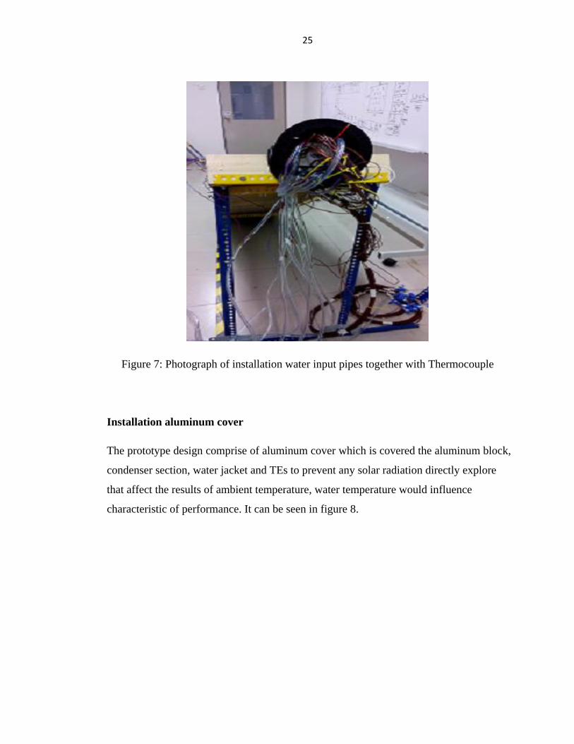
Figure 7: Photograph of installation water input pipes together with Thermocouple
Installation aluminum cover
The prototype design comprise of aluminum cover which is covered the aluminum block,
condenser section, water jacket and TEs to prevent any solar radiation directly explore
that affect the results of ambient temperature, water temperature would influence
characteristic of performance. It can be seen in figure 8.
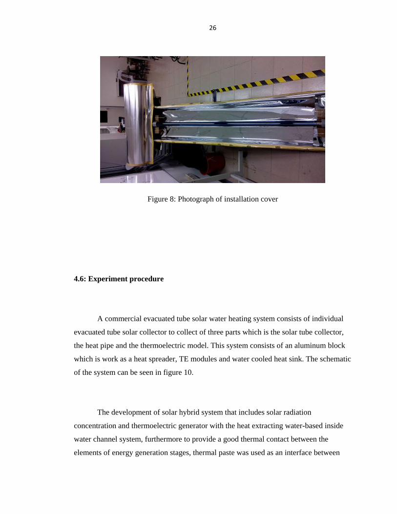
26
Figure 8: Photograph of installation cover
4.6: Experiment procedure
A commercial evacuated tube solar water heating system consists of individual
evacuated tube solar collector to collect of three parts which is the solar tube collector,
the heat pipe and the thermoelectric model. This system consists of an aluminum block
which is work as a heat spreader, TE modules and water cooled heat sink. The schematic
of the system can be seen in figure 10.
The development of solar hybrid system that includes solar radiation
concentration and thermoelectric generator with the heat extracting water-based inside
water channel system, furthermore to provide a good thermal contact between the
elements of energy generation stages, thermal paste was used as an interface between

27
heat sink and heat source that can easily be implemented as heat transfer system. Besides
that, thermoelectric is the direct conversion of a temperature different imposed between
the junctions of two types different materials to generated electricity as known as the
See-back effect. See-back effect also can determined as when an electric current flow
through a circuit composed of two different conductor, heat will be liberated at one
junction and absorbed at the other which is depending on the current flow direction
( Peltier effect).
In order to obtain both effects, combined heat pipes in a thermoelectric (TE)
device used for hybrid system could provide both power generation and heat
simultaneously. Typically, the cold side of the thermoelectric cooler is in contact with
the thermoelectric chip to maintain the chip temperatures below its design temperature
with natural or forced convection at the hot side of the TE modules to carrier the heat
from the thermoelectric chip and the applied power to the TE modules to the ambient.
The performance of the system relay upon the design and geometric dimensions
of the collector, insulation, connecting pipe size, relative angle (30 degree) also
environmental factors such as weather and wind conditions to justify the temperature
that can be achieved. Next, insulation inside the tank would determine the heat losses
will lead to performance drop during the experiments. Such as this case, the solar tank
will insulate with thermal resistance rubber that could reduce emissivity heat losses
during analyze in this work.
The idea of this design is that solar energy will be collected by the solar tube
collector when exposed to sunlight and transferred to the evaporator section of the heat
pipe inside the solar tube collector and the heat pipe will then transferred this energy to
the condenser section thus heat up the aluminum block. Meanwhile the aluminum block
works as heat spreader as transfers and spreads the energy toward the TE module which

28
are placed along and in contact with the condenser section and other surface of the TE
module is cooled with water jacket and water from water tank would flow through the
water cooled heat sink to absorb heat energy through the TE module thus create a
temperature different between both sides to gain in TE power generation and water
heating simultaneously. A diagram depicting the flow of the heat transfer through a
commercial solar heater of the hybrid system is shown in figure 9.
Figure 9: Flow of heat energy in a solar water heater and Flow of energy in the solar /
heat pipe / TE hybrid system

29
Procedure:
1. Evacuated tube solar collector exposed to sunlight.
2. Water from water tank flow through the aluminum cooling water channel.
3. Thermocouple wire connected with terminal channels.
4. AC power supply used to supply to Graphtec GL820 data logger.
5. Three terminal channels directly connected with Graphtec GL820 data logger.
6. Data record started, temperature and voltage measurements were recording on per
mine basic to ascertain the steady-state system.
7. Data logger will record the temperature data and the performance of thermoelectric
will be determined via tabulated results.
8. kipp & onen Solarimeter were placed with an angle same as experiment rig at an open
area to detect the solar radiation absorb by the rig.
9. kipp & onen Solarimeter measured and recorded through the day of solar radiation
performance.
10. Data record started solar radiation measurements were recording on per mine basic
to ascertain the steady-state system.
11. Solar radiation data direct connected onto a computer will be determined via
performance results.
30
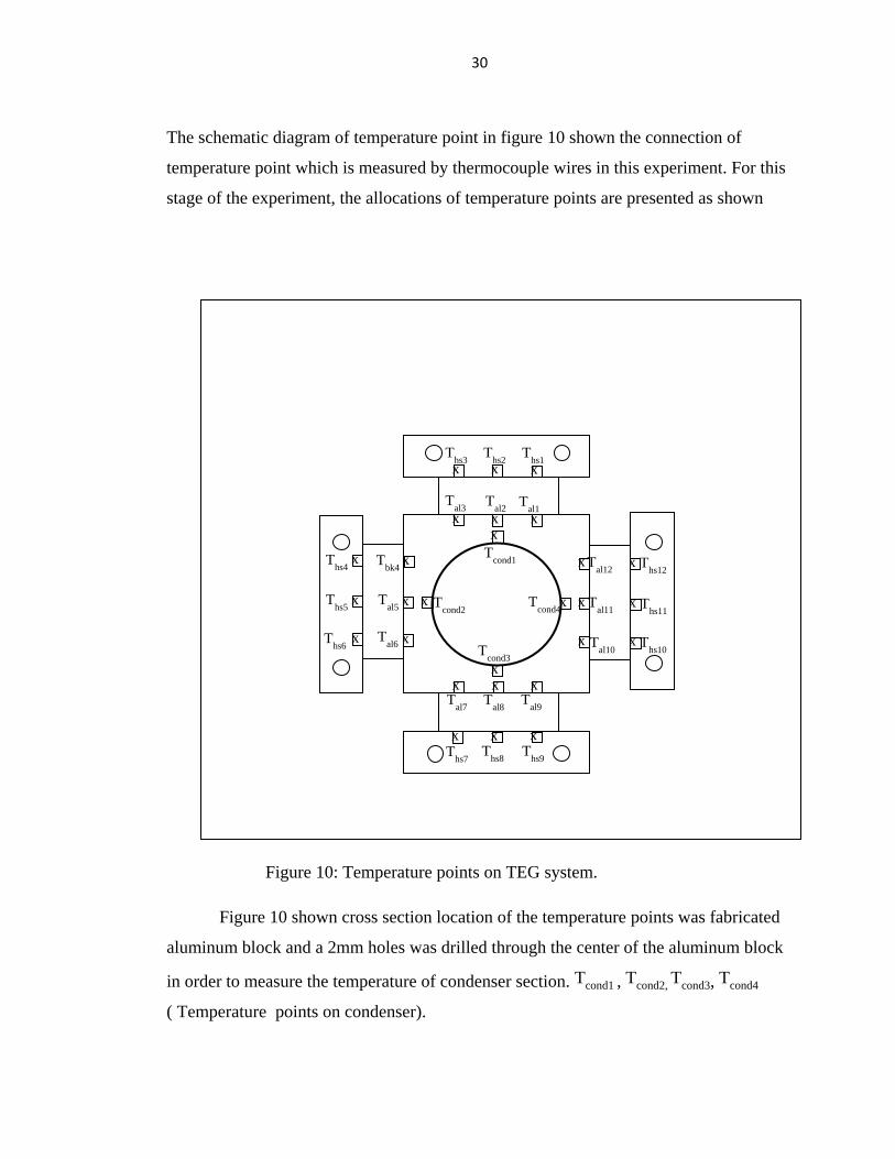
The schematic diagram of temperature point in figure 10 shown the connection of
temperature point which is measured by thermocouple wires in this experiment. For this
stage of the experiment, the allocations of temperature points are presented as shown
Figure 10: Temperature points on TEG system.
Figure 10 shown cross section location of the temperature points was fabricated
aluminum block and a 2mm holes was drilled through the center of the aluminum block
in order to measure the temperature of condenser section. Tcond1 , Tcond2, T
cond3, Tcond4
( Temperature points on condenser).
X
x
x
x
x x x
x
x
x
x
x
x x
x x x
x x
x
x
x x
x
x
x
x x x
Ths1
Ths2
Ths3
Ths4
Ths5
Ths6
Ths7
Ths8
Ths9
Ths10
Ths11
Ths12
Tbk4
Tal1
Tal2
Tal3
Tal5
Tal6
Tal7
Tal8
Tal9
Tal10
Tal11
Tal12
T
cond1
Tcond2
Tcond3
Tcond4

31
Meanwhile Tal1,
Tal2,
Tal3,
Tal4,
Tal5,
Tal6,
Tal7,
Tal8,
Tal9,
Tal10,
Tal11,
Tal12 (Temperature
points on aluminum block) those temperature points was located at the outer surface of
each side of the aluminum block where 12 temperature points are measured to measure
the temperature of the surface that can be provides even for the large surface area for
optimized heat performance.
Other than that, Ths1, T
hs2, T
hs3, T
hs4, T
hs5, T
hs6, T
hs7, T
hs8, T
hs9, T
hs10, T
hs11, T
hs12
(Temperature points on heat sink) is measure aluminum H-type cooling water jacket for
the surface area of cold junction
The proposed hybrid system would undergo an outdoor performance test at
UTAR top roof which the solar energy as a heat source for system will be evaluated and
analyzed. Moreover, the system is set 30 degree angle on top of a fabricated metal stand.
Figure 11: Temperature points on evacuated tube solar water heating system
The temperature pints measured for this system shown in Figure 11 provides a large
heat input as heating section in the evaporator area of heat pipes Te1,
Te2,
Te3
(Temperature points on heat pipe evacuated tube ) used to represent the solar energy that
Water-cooled heat sink
Thermoelectric module
Heat pipe
(8.2)
x x x x
x
Te3
Te2
Tadb
Tatm
Te1
32
obtained from exposure to sunlight converted in to heat energy. The system also
investigated Tadb (Temperature points on heat Adiabatic ) that will be evaluated and
analyzed. Next is Tatm (Temperature points on atmosphere ) measured by thermocouple
wires in this experiment.
4.3 Experimental Results
Figures 12 to figure 27 demonstrate every one of the charts of experimental
results from Runs 1 to 4 with diverse with different flow rate and temperature condition.
Figure 12to figure 27 shows the repeatability test run 1 to run 4. Besides that, figure 12,
figure 13, figure 14 and figure 15 was typical experimental results which is indicated the
solar radiation and ambient temperature in different coolant flow rate 0.9 g/s, 1.5 g/s ,
and good weather condition 0.9 g/s. Next, the figure 16 to figure 19 was the typical
experimental results of heat pipe and condenser temperature in different coolant flow
rate conditions results the different values. In additional, figure 20, figure 21, figure 22
and figure 23 also results the different TE both side temperature condition was show in
run1, run 2, run 3 and run 4. Lastly, the figure 24 to figure 27 was indicated the
experimental results of temperature efficiency performed by different coolant flow rate
and temperature different in run1, run2, run3 and run 4.

33
Figure 12 Typical experimental results showing solar radiation, ambient temperature (coolant flow rate = 0.9 g/s)(run 1)
33

34
Figure 13 Typical experimental results showing solar radiation, ambient temperature (coolant flow rate = 1.5 g/s)(run 2)
34

35
Figure 14 Typical experimental results showing solar radiation, ambient temperature (coolant flow rate = 8.33 g/s)(run 3)
35

36
Figure 15 Typical experimental results showing solar radiation, ambient temperature (coolant flow rate = 0.9 g/s)(run 4)
36

37
Figure 16 Typical experimental results showing heat pipe and condensor temperature (coolent flow rate = 0.9)(run 1)
37

38
Figure 17 Typical experimental results showing heat pipe and condensor temperature (coolent flow rate = 1.5)(run 2)
38
39
Figure 18 Typical experimental results showing heat pipe and condensor temperature (coolent flow rate = 8.33)(run 3)
39

40
Figure 19 Typical experimental results showing heat pipe and condensor temperature (coolent flow rate = 0.9)(run 4)
40

41
Figure 20 Typical experimental results showing TE hot side and cold side temperature (coolent flow rate = 0.9 g/s)(run 1)
41

42
Figure 21 Typical experimental results showing TE hot side and cold side temperature (coolent flow rate = 1.5 g/s)(run 2)
42

43
Figure 22 Typical experimental results showing TE hot side and cold side temperature (coolent flow rate = 8.33 g/s)(run 3)
43
44
Figure 23 Typical experimental results showing TE hot side and cold side temperature (coolent flow rate = 0.9 g/s)(run 4)
44

45
Figure 24 Typical experimental results showing thermal efficiency and water input and output temperature (coolent flow rate = 0.9
g/s)(run 1)
45

46
Figure 25 Typical experimental results showing thermal efficiency and water input and output temperature (coolent flow rate = 1.5
g/s)(run 2)
46

47
Figure 26 Typical experimental results showing thermal efficiency and water input and output temperature (coolent flow rate = 8.33
g/s)(run 3)
47

48
Figure 27 Typical experimental results showing thermal efficiency and water input and output temperature (coolent flow rate = 0.9
g/s)(run 4)
48

49
Chapter 5
Discussion of Results
Experiments were conducted from throughout the day from 10.00 - 17.00 hrs at various
coolant water mass flow rates.
Weather conditions fluctuate widely in the tropics. Typical results obtained are plotted
every 5 mins which is started form 10.00 – 17.00 hrs. The following observations were
made:
1. Except for some fluctuation in the morning around 10.00 – 11.00 hrs, the
radiation pattern was quite smooth, peaking around 13.00 hr to about 900
W/m2.
2. All temperatures increased throughout the day and peaked around 15.00
hr.
3. Maximum ambient temperature was about 36oC.
4. Variations in fin temperatures (Thp1 – Thp3) at the evaporator section were
observed with maximum values from about 90 – 96oC.
5. Maximum adiabatic temperature (Tad) was about 85oC.

50
6. Maximum condenser temperatures (Tcond1 – Tcond4) varied from about 82
– 84oC.
7. Water outlet temperature (Two) varied by about 1- 8oC.
5.1 Solar radiation and ambient temperature variation
The effectiveness of this experiment relies on upon a few climatic factors, for example,
the efficiency obtained by solar radiation hence affecting the ambient temperature also
the performance respectively. The simulated result obtained shown temperature do not
stay steady throughout the day, however change impressively. It is then worth
examination the impact the optimized system. For several temperature data 10.00 to
17.00 hour which resulted around 13.30 hour was presented the peak values of solar
radiation and for a maximum ambient temperature was achieved 36 degree. However it
is decrease towards the evening in term of temperature regulation. Figure 12 to figure 15
displayed the collected data have been analyzed as an element of solar radiation for run
1 to run 4 when the ambient temperature found in the day, due to the transition of cloud
and wind characteristics during the system performed. This experiment was carried out
an investigation on both 0.9g/s flow rate with different weather condition. The
temperature different for figure 24 was 5 degree and figure 27 shows the temperature
different obtain throughout the day was 8 degree. Therefore, the efficiency of heating
can be determined by weather condition.

51
5.2 Heat pipe evaporator condenser temperature
Figure 16,figure 17, figure 18, and figure 19 was conducted to investigate the
performance of heating temperature performed where the flow rate of water was fixed
at 0.9g/s, 1.5g/s and 8.33g/s. The amount of radiation received of day thus to provide
heat transfer to rise up the aluminum block. This show that there is temperature build up
from 23 degree to 97 degree whereas the maximum condenser temperature of 90 degree
to 96 degree.
5.3 Influence of flow rate of water
The efficiency of the system was shown in this experiment and flow rate of water on the
performance of water heating stated at the flow rate at 0.9g/s, 1.5g/s and 8.33g/s. It was
presented in figure 24, figure 25, figure 25 and figure 26 where the heating temperature
was in various conditions. The results has shown that the flow rate influencing the
temperature different over the module is between 1- 8 percents. These results obtained
during 8 hour throughout the day. Consequently, the higher the heating temperature, the
bigger the temperature difference between water inlet 27 degree to 32 degree and water
outlet was 29 to 35 degree somewhere. Due to the temperature different, provided at the
condenser section of the heat pipe with the TE modules cold side temperature, heat
energy dissipates through the interaction whereby water cooled jacket to ovartake the
heat input from the TE surface. These are demonstrated in run 1, run 2 and run 3, heat
flow by conduction through few components, for example, aluminum condenser, TE
modules and heat transfer happens from different surface by convection and radiation.
Heat is additionally added to the space between the human setup errors and used of
equipments. It can be seen that the output performances of water heating temperature
was 5, 3 and 0.3 degree of average simultaneously. The simulated thermal efficiency
demonstrates the impact of heat conductivity and the maximum condition of solar

52
irradiation 1000w/m2. Refer to equation 1 stated in theoretical calculation, the heat
transfer rate was calculated as 18.82W, 18.82W and 10.45W. Meanwhile, the
performance of the system show the thermal efficiency from equation 2 was 163.8%,
132% and 152.8% of average simultaneously. The overall efficiency obtained based on
measured the heat transfer rate, solar radiation and are of evaporator. The results shown
were greater than 100% of thermal efficiency because of internal heat energy store in
aluminum spreader. It can be explain that the temperature keep at thermal equilibrium
while solar radiation energy exposed fluctuations hence increase in thermal efficiency.
5.4 TE modules temperature
Based on the information at the previously stated of different flow-rate was fixed which
is 0.9g/s, 1.5g/s and 8.33g/s shown in figure 20, figure 21, figure 22 and figure 23. The
temperature different at the hot and cold sides TE modules at different flow rates are
plotted whereby variation of both TE modules side temperature was 26.711 degree, 26.7
degree, 30.4 degree and 30.5 degree consequently. The successful heat transfer between
the TE module„s ceramic plate cold side and the water jacket and it may be set to be a
proportionate steady value. In additional, a good thermal insulation prompts a better
prevention of heat lose. It can additionally be seen that the effect of thermal protection
gets to be littler with expanded the amount of TE modules. Next, the heat conduction
between the hot side and cold side of the TE module additions may generate a littler
temperature different and thus created 1-8 degree water heating.
An analysis model was created by MatCad software based on thermodynamic
hypothesis and law of conservation of energy studied. The model was considered
number of TE module, for example, temperature of heat source and heat sink or water
cooled jacket, contact resistance, geometry of the system also the environment condition

53
was counted into model. The results demonstrate that all TE modules and equipments
have the same characteristic parameters and work in the same conditions.
During the experimental test, the parameters of four TE modules are fixed in
more and likely parameters. In addition, the run was conducted in experiments have
slightly different in related of water jacket structure hence affecting the temperature of
the water channel which will then affect the temperature different across the TE module.
Other than that, the internal resistances of TE module are not inherent parameter thus a
significant amount of different reflects the different thermal performances in system.
Beside on that, the analysis model value is slight greater than the test results as a
consequence of the supposition which miss conduct with the heat conduction between
the thermocouples. Other than that, the place the thermocouple wires, surface not
completion , equity of water jacket and improper installation may lead the decrease of
thermal contact thus to created mistake during experimental was performed.

54
Chapter 6
Suggestion for future studies
Two proposals for future studies are suggested as below:
1. Increase the number of heat pipe to enhance the thermal performance
2. Water cooling jacket connected in series
55
Chapter 7
Conclusion
The performance of the solar/ heat-pipe/ water heating system was investigated and the
thermal efficiency of the system performance was found to be more than 100 percent
efficiency. This is obtained by a decrease in solar radiation exposed with internal heat
energy come from an aluminum block. However, it is being halved due to semi-exposure
to the sunlight throughout the solar evacuated tube.

56
References
1. Yan, Weiguo, Xiaoli Yu, and Guodong Lu. 'Experimental Measurement And
Analysis Of Performance Of Heat Pipe Heat Exchanger Used In A Turbocharged
Engine With Intercooling'. Heat Transfer Engineering 33.14 (2012): 1207-1216.
Web.
2. Ren Yan ; Zhang Lihong ; Liang Huimin, Analysis of Influencing Factors of
Heat Transfer Performance of Heat Pipe Heat Exchanger” Coll. of Urban Constr.,
Hebei Univ. of Eng., Handan, China
3. Date, Ashwin et al. 'Theoretical and Experimental Study on Heat Pipe Cooled
Thermoelectric Generators With Water Heating Using Concentrated Solar
Thermal Energy'. Solar Energy 105 (2014): 656-668. web.
4. He, Wei et al. 'A Study On Incorporation Of Thermoelectric Modules With
Evacuated-Tube Heat-Pipe Solar Collectors'. Renewable Energy 37.1 (2012):
142-149. Web.
5. Zhang, Ming et al. 'Efficient, Low-Cost Solar Thermoelectric Cogenerators
Comprising Evacuated Tubular Solar Collectors And Thermoelectric Modules'.
Applied Energy 109 (2013): 51-59. Web.
6. Gang, Pei et al. 'Annual Analysis Of Heat Pipe PV/T Systems For Domestic Hot
Water And Electricity Production'. Energy Conversion and Management 56
(2012): 8-21. Web.
57
7. J.S Lee, S.H. Rui et al , “ use of two-phase loop thermosyphons for
thermoelectric refrigeration: experimental and analysis,” Applied thermal
engineering, vol 23,pp.1167-1176,2003
8. Nkwetta, Dan Nchelatebe, and Mervyn Smyth. 'Performance Analysis And
Comparison Of Concentrated Evacuated Tube Heat Pipe Solar Collectors'.
Applied Energy 98 (2012): 22-32. Web.
9. Zhang, Xinyu et al. 'Experimental Investigation Of The Higher Coefficient Of
Thermal Performance For Water-In-Glass Evacuated Tube Solar Water Heaters
In China'. Energy Conversion and Management 78 (2014): 386-392. Web.
10. Liu, Zhen-Hua et al. 'Thermal Performance Of An Open Thermosyphon Using
Nanofluid For Evacuated Tubular High Temperature Air Solar Collector'. Energy
Conversion and Management 73 (2013): 135-143. Web.
11. W.He,Y.Su et al. “ A study on incorporation of thermoelectric systems with
thermosyphons,” solar energy, vol.85,pp.2843-2855,2011.
12. I.Sateikis,R.Ambrulevicius and S.Lyniene, “ Investigation of a micro power
thermoelectric generator operation at a low temperature different,” Electronics
and Electrical Engineering, vol.10.113-116,2011.
13. G.Liang, J.Zhou and X.Hiuang,”Analytical model of parallel thermoelectric
generator,” Applied Energy, vol.88,pp.5193-5199,2011.
14. N.M.Khattab and E.T. Shenawy,”Optimal operation of thermoelectric cooler
driven by solar thermoelectric generator,” Energy conversion and management,
vol.47,pp.407-426,2006.
15. E.A.Chavez-Urbiola,Y.V. Vorobiev and L.P.Bulat, “Solar hybrid systems with
thermoelectric generators,” Solar Energy ,pp.369-378,2012.

58
16. C.Lertsatithanakorn,N.Khasee, S.Attharharuyakul and soponronnarit,
“ Performance analysis of a double-pass thermoelectric solar air collector,” Solar
Energy Material and Solar cell, vol.92,pp.110-1109,2008.
17. N.Rahbar et al,” Experimental study of a novel portable solar still by utilizing the
heat pipeand thermoelectric module,” Resalination, vol.284,pp.55-61,2012.
18. S.Maneewan et al, “ Investigation on generated power of thermoelectric roof
solar collector,” Renewable energy,vol.29.pp.743-752,2004.
19. N.Milijkovic and E.N. Wang, “ Modeling and optimization of hybrid solar
thermoelectric system with thermosyphons,” Solar energy, vol.85,pp.2843-
2855,2011.
20. M.Zhang et al, “Efficient, low-cost solar thermoelectric co-generators
comprising of evacuated tubular solar collectors and thermoelectric modules,”
Applied Energy, vol.109,pp.51

59
60

61

62

63
64

65

66

67

68

69

70


![0 R STAA - Institut für Angewandte Physik [IAP/TU Wien]gebeshuber/ICMAT11_Book_of...Rahul AGARWAU'+, Jin XIP, Kia Hian LAU, Praveen KUMAR SAMPATHI, Nagarajan RANGANATHANI, Janak SINGHI,](https://cdn.vdocument.in/doc/165x107/5aaa5f067f8b9a95188e0004/0-r-staa-institut-fr-angewandte-physik-iaptu-wien-gebeshubericmat11bookofrahul.jpg)
![WELCOME []Imelda M. Loho International Advisors National Advisors Dong Jin Suh George K Lau J H Kao Ji-Dong Jia Jin L Hou Masao Omata Osamu Yokosuka Shiv K Sarin Teerha Piratvisuth](https://cdn.vdocument.in/doc/165x107/5f0e84ef7e708231d43fa2d3/welcome-imelda-m-loho-international-advisors-national-advisors-dong-jin-suh.jpg)
