
Hydraulic and lubrication oil filters Technical data sheets
Filtration Products

Hydraulic and lubrication oil filter technical data sheets
Table of contentsClick on model numbers below to view technical data sheets
Series High pressure filters Series FHP Pressure filter, front manifold mounted - 3625 PSI
FHP 60-150
Series HPF Pressure filter, manifold mounted - 4568 PSI
HPF 60-450
HPF 601-1351
HPF/HPFO 30
Series HPP Pressure filter, top manifold mounted - 4568 PSI
HPP 60-450
HPP 601-1351
Series HPU Pressure filter, top manifold mounted - 4568 PSI
HPU 601-1351
Series HPW Pressure filter for reversable filtration - 4568 PSI
HPW 60-450
HPW 601-1351
Series HPX Pressure filter, manifold mounted - 4568 PSI
HPX 60-150
HPX 170-450
HPX 601-1351
Series HPY Pressure filter, manifold mounted- 4568 PSI
HPY 60-150
HPY 170-450
Series HPZ Pressure filter for sandwich stacking - 5075 PSI
HPZ 32
HPZ 90
Series HP Pressure filter in line - 6000 PSI
HP 31
HP 61
HP 170-450
HP 171-451
HP 601-1351
Series HPV Pressure filter with differential pressure-valve - 6000 PSI
HPV 60-150
HPV 170-450
Series Medium pressure filters Series MF Medium pressure filter, manifold mounted - 2320 PSI
MF/MFO 30
Series ML Standard in-line filter-medium pressure range - 2320 PSI
ML 170-450
ML/MLO 30
Series MNL Standard in-line filter-medium pressure range according to DIN 24550 T1, T2 - 2320 PSI
MNL 40-100
Series MDV Medium pressure filter with differential pressure-valve - 2900 PSI
MDV 40-63
Series Low pressure filters
Series LF In-line low pressure filter - 464 PSI
LF 63
LF 101
LF 251-1100
LF 1950-2200
LF 2005-4005
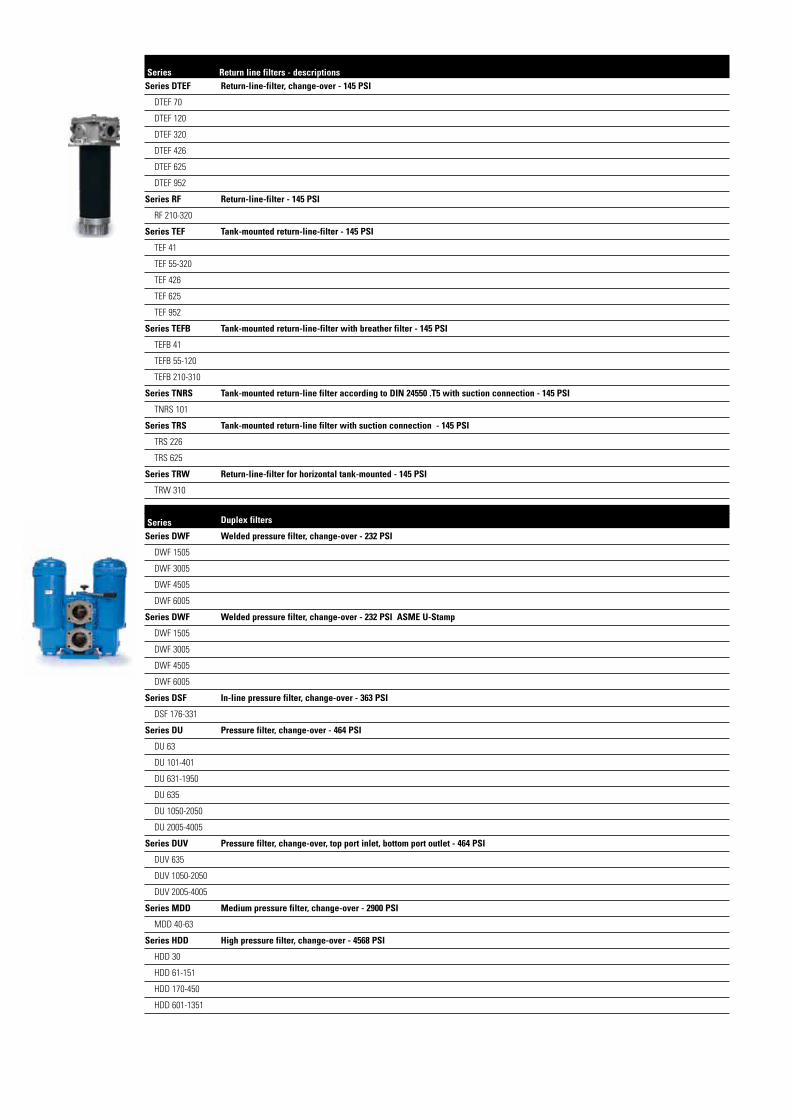
Series Return Line Return line filters - descriptionsFSeries DTEF 145 PSI
Series DTEF Return-line-filter, change-over - 145 PSI
DTEF 70
DTEF 120
DTEF 320
DTEF 426
DTEF 625
DTEF 952
Series RF Return-line-filter - 145 PSI
RF 210-320
Series TEF Tank-mounted return-line-filter - 145 PSI
TEF 41
TEF 55-320
TEF 426
TEF 625
TEF 952
Series TEFB Tank-mounted return-line-filter with breather filter - 145 PSI
TEFB 41
TEFB 55-120
TEFB 210-310
Series TNRS Tank-mounted return-line filter according to DIN 24550 .T5 with suction connection - 145 PSI
TNRS 101
Series TRS Tank-mounted return-line filter with suction connection - 145 PSI
TRS 226
TRS 625
Series TRW Return-line-filter for horizontal tank-mounted - 145 PSI
TRW 310
Series Duplex filters Series DWF Welded pressure filter, change-over - 232 PSI
DWF 1505
DWF 3005
DWF 4505
DWF 6005
Series DWF Welded pressure filter, change-over - 232 PSI ASME U-Stamp
DWF 1505
DWF 3005
DWF 4505
DWF 6005
Series DSF In-line pressure filter, change-over - 363 PSI
DSF 176-331
Series DU Pressure filter, change-over - 464 PSI
DU 63
DU 101-401
DU 631-1950
DU 635
DU 1050-2050
DU 2005-4005
Series DUV Pressure filter, change-over, top port inlet, bottom port outlet - 464 PSI
DUV 635
DUV 1050-2050
DUV 2005-4005
Series MDD Medium pressure filter, change-over - 2900 PSI
MDD 40-63
Series HDD High pressure filter, change-over - 4568 PSI
HDD 30
HDD 61-151
HDD 170-450
HDD 601-1351

Series Stainless steel filters Series EHD Stainless steel-pressure filter, change-over - 4568 PSI
EHD 61-151
EHD 241-451
Series EHPF Stainless steel pressure filter, manifold mounted - 4568 PSI
EHPF 60-150
EHPF 170-450
Series EH Stainless steel-pressure filter - 6000 PSI
EH 31
EH 60-150
EH 240-450
EH 601-1351
Series EHP Pressure filter, front manifold mounted - 11600 or 20300 PSI
EHP 31
EHP 60-90
Series Suction filters Series AS Suction filter
AS 220
AS 632
Series TS Suction filter for vertical tank-mounting
TS 210-310
TS 426
TS 625
Series TSW Suction filter for horizontal tank-mounting
TSW 210-310
TSW 426
TSW 625
Series Off-line filters Series NF Partial flow filter 232 PSI
NF 250
NF 631
NF 1000
Series Indicators Series E/O
Series AOR/AOC
Series AE
AE Block
AE Thread
Series OP/OE
OP/OE Block
OP/OE Thread
Series VS5
VS5 Block
VS5 Thread

Series FHP 60-150
3625 PSI
PRESSURE FILTER, manifold mounted Sheet No. 1474 J
EDV 09/15
1) Connect the stand grounding tab toa suitable earth ground point.
Dimensions: inches
Designs and performance values are subject to change.
Dimensions:
type FHP 60 FHP 90 FHP 150 connection ¾“
A 8.35 10.90 15.12B 10.63 13.19 17.52
weight approx. 11 lbs. 12 lbs. 14 lbs. volume tank .08 gal. .10 gal. .16 gal.

Pressure Filter
Series FHP 60-150
3625 PSI
Description: Pressure filter series FHP 60-150 have a working pressure up to 3625 PSI. Pressure peaks can be absorbed with a sufficient safety margin. The FHP-filter are flange mounted to the hydraulic system.
The filter element consists of star-shaped, pleated filter material, which is supported on the inside by a perforated core tube and is bonded to the end caps with a high-quality adhesive. The flow direction is from outside to inside. Filter elements are available down to 4 µm(c).
Eaton filter elements are known for high intrinsic stability and an excellent filtration capability, a high dirt-retaining capacity and a long service life.
Eaton filter elements can be used for petroleum-based fluids, HW emulsions, water glycols, most synthetic fluids and lubrication fluids. Consult factory for specific fluid applications.
Eaton filter elements are available up to a pressure resistance of p 2320 PSI and a rupture strength ofp 3625 PSI.
The internal valve is integrated into the filter head. After reaching the bypass pressure setting, the bypass valve will send unfiltered partial flow around the filter.
The reversing valve provides another level of protection for the filter element. The reverse flow will not be filtered.
1. Type index:
1.1. Complete filter: (ordering example)
FHP. 90. 10VG. HR. E. P. -. F. 4. -. -. AE1 2 3 4 5 6 7 8 9 10 11 12
1 series: FHP = pressure filter, manifold mounted
2 nominal size: 60, 90, 150
3 filter-material and filter-fineness: 80G, 40G, 25G, 10G stainless steel wire mesh 25VG, 16VG, 10VG, 6VG, 3VG microglass
4 filter element collapse rating: 30 = p 435 PSI HR = p 2320 PSI (rupture strength p 3625 PSI)
5 filter element design: E = single-end open
6 sealing material: P = Nitrile (NBR) V = Viton (FPM)
7 filter element specification: (see catalog) - = standard
VA = stainless steel IS06 = for HFC applications, see sheet-no. 31601
8 process connection: F = manifold mounted
9 process connection size: 4 = ¾“
10 filter housing specification: (see catalog) - = standardIS06 = for HFC applications, see sheet no.31605
11 internal valve: - = without
S1 = with bypass valve p 51 PSI S2 = with bypass valve p 102 PSI
R = reversing valve, Q ≤ 18.50 GPM
12 clogging indicator or clogging sensor: - = withoutAOR = visual, see sheet-no. 1606 AOC = visual, see sheet-no. 1606 AE = visual-electric, see sheet-no. 1615 VS5 = electronic, see sheet-no. 1619
To add an indicator to your filter, use the corresponding indicator data sheet to find the indicator details and add them to the filter assembly model code.
1.2. Filter element: (ordering example)
01E. 90. 10VG. HR. E. P. - 1 2 3 4 5 6 7
1 series: 01E. = filter element according to company standard
2 nominal size: 60, 90, 150
3 - 7 see type index-complete filter

Technical data:
design temperature: 14 °F to +212 °F operating temperature: 14 °F to +176 °F operating medium mineral oil, other media on request max. operating pressure: 3625 PSI test pressure: 5184 PSI process connection: manifold mounted housing material: C-steelsealing material: Nitrile (NBR) or Viton (FPM), other materials on requestinstallation position: vertical
Classified under the Pressure Equipment Directive 2014/68/EC for mineral oil (fluid group 2), Article 4, Para. 3. Classified under ATEX Directive 2014/34/EC according to specific application (see questionnaire sheet-no. 34279-4)
Pressure drop flow curves:
Filter calculation/sizing
The pressure drop of the assembly at a given flow rate Q is the sum of the housing ∆p and the element ∆p and is calculated as follows:
p assembly = p housing + p element p housing = (see p = f (Q) - characteristics)
p element (PSI) = .
³
For ease of calculation our Filter Selection tool is available online at www.eatonpowersource.com/calculators/filtration/
Material gradient coefficients (MSK) for filter elements
The material gradient coefficients in PSI/GPM apply to mineral oil (HLP) with a density of 0.876 kg/dm³ and a kinematic viscosity of 139 SUS (30 mm²/s). The pressure drop changes proportionally to the change in kinematic viscosity and density.
FHP VG G
3VG 6VG 10VG 16VG 25VG 25G 40G 80G
60 6.748 4.685 2.999 2.577 1.760 0.2002 0.1868 0.1280
90 4.059 2.818 1.804 1.550 1.059 0.1210 0.1130 0.0774
150 2.422 1.681 1.076 0.925 0.632 0.0723 0.0675 0.0462
∆p = f(Q) – characteristics according to ISO 3968
The pressure drop characteristics apply to mineral oil (HLP) with a density of 0.876 kg/dm³. The pressure drop changes proportionally to the density.

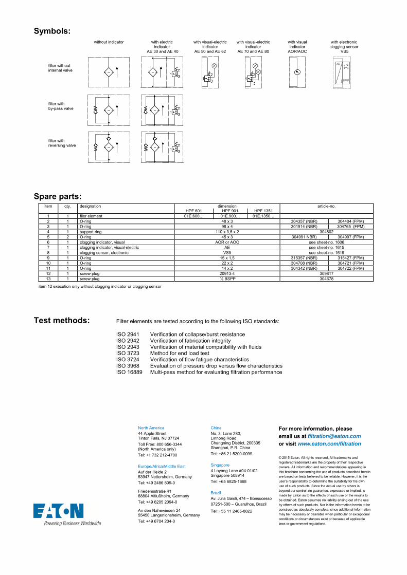
Symbols:
without indicator with electric indicator
AE 30 and AE 40
with visual-electric indicator
AE 50 and AE 62
with visual-electric indicator
AE 70 and AE 80
with visual indicator
AOR/AOC
with electronic clogging sensor
VS5 filter without internal valve
filter with by-pass valve
filter with reversing valve
Spare parts:
item qty. designation dimensions article-no. FHP 60 FHP 90 FHP 150
1 1 filter element 01E.60… 01E.90… 01E.150… 2 1 O-ring 22 x 3,5 304341 (NBR) 304392 (FPM) 3 1 O-ring 54 x 3 304657 (NBR) 304720 (FPM) 4 1 support ring 61 x 2,6 x 1 304660 5 2 O-ring 18 x 2,5 304371 (NBR) 6 1 screw plug ¼ BSPP 305003 7 1 clogging indicator, visual AOR or AOC see sheet-no. 1606 8 1 clogging indicator, visual-electric AE see sheet-no. 1615 9 1 clogging sensor, electronic VS5 see sheet-no. 1619
10 1 O-ring 15 x 1,5 315357 (NBR) 315427 (FPM) 11 1 O-ring 22 x 2 304708 (NBR) 304721 (FPM) 12 1 O-ring 14 x 2 304342 (NBR) 304722 (FPM) 13 1 screw plug 20913-4 309817
item 13 execution only without clogging indicator or clogging sensor
Test methods: Filter elements are tested according to the following ISO standards:
ISO 2941 Verification of collapse/burst resistance ISO 2942 Verification of fabrication integrity ISO 2943 Verification of material compatibility with fluids ISO 3723 Method for end load test ISO 3724 Verification of flow fatigue characteristics ISO 3968 Evaluation of pressure drop versus flow characteristics ISO 16889 Multi-pass method for evaluating filtration performance
North America 44 Apple Street Tinton Falls, NJ 07724
Toll Free: 800 656-3344 (North America only)
Tel: +1 732 212-4700 Europe/Africa/Middle East Auf der Heide 2 53947 Nettersheim, Germany
Tel: +49 2486 809-0
Friedensstraße 41 68804 Altlußheim, Germany
Tel: +49 6205 2094-0
An den Nahewiesen 24 55450 Langenlonsheim, Germany
Tel: +49 6704 204-0
China No. 3, Lane 280, Linhong Road Changning District, 200335 Shanghai, P.R. China
Tel: +86 21 5200-0099 Singapore 4 Loyang Lane #04-01/02 Singapore 508914
Tel: +65 6825-1668 Brazil Av. Julia Gaioli, 474 – Bonsucesso 07251-500 – Guarulhos, Brazil
Tel: +55 11 2465-8822
For more information, please email us at [email protected]
or visit www.eaton.com/filtration
© 2015 Eaton. All rights reserved. All trademarks and registered trademarks are the property of their respective owners. All information and recommendations appearing in this brochure concerning the use of products described herein are based on tests believed to be reliable. However, it is the user’s responsibility to determine the suitability for his own use of such products. Since the actual use by others is beyond our control, no guarantee, expressed or implied, is made by Eaton as to the effects of such use or the results to be obtained. Eaton assumes no liability arising out of the use by others of such products. Nor is the information herein to be construed as absolutely complete, since additional information may be necessary or desirable when particular or exceptional conditions or circumstances exist or because of applicable laws or government regulations.

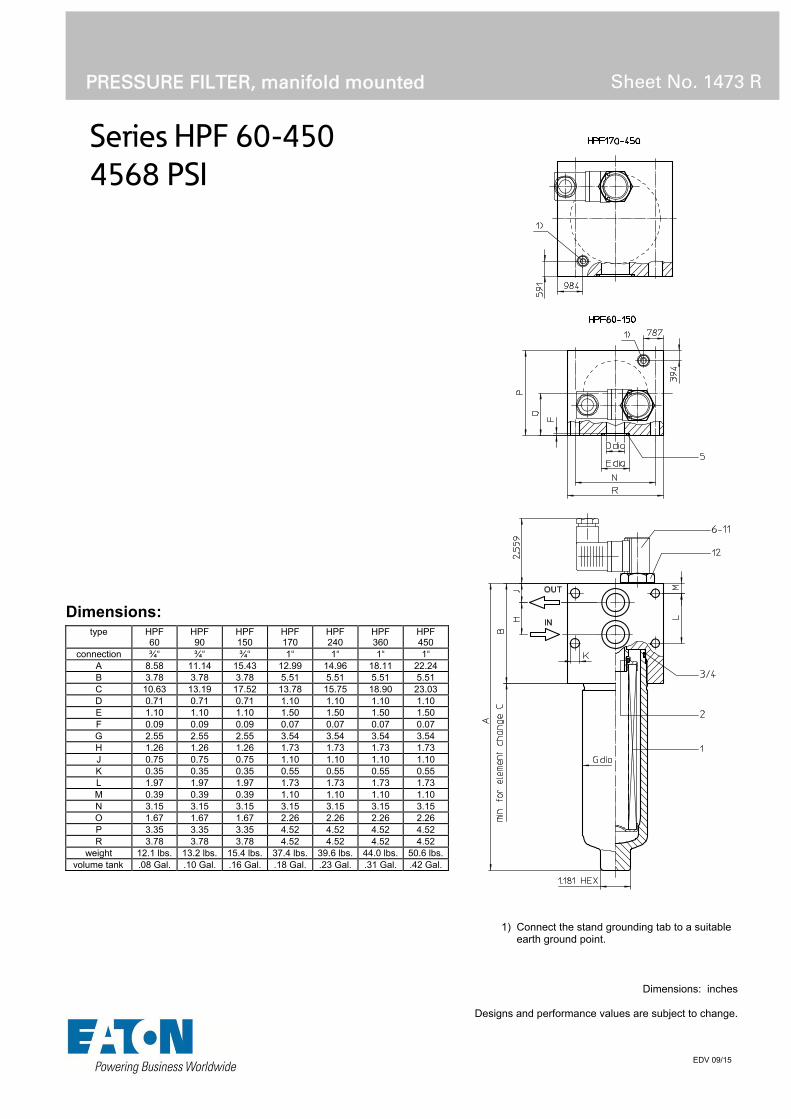
Series HPF 60-450
4568 PSI
PRESSURE FILTER, manifold mounted
Sheet No. 1473 R
EDV 09/15
1) Connect the stand grounding tab to a suitable earth ground point.
Dimensions: inches Designs and performance values are subject to change.
Dimensions:
type HPF 60
HPF 90
HPF 150
HPF 170
HPF 240
HPF 360
HPF 450
connection ¾“ ¾“ ¾“ 1“ 1“ 1“ 1“ A 8.58 11.14 15.43 12.99 14.96 18.11 22.24 B 3.78 3.78 3.78 5.51 5.51 5.51 5.51 C 10.63 13.19 17.52 13.78 15.75 18.90 23.03 D 0.71 0.71 0.71 1.10 1.10 1.10 1.10 E 1.10 1.10 1.10 1.50 1.50 1.50 1.50 F 0.09 0.09 0.09 0.07 0.07 0.07 0.07 G 2.55 2.55 2.55 3.54 3.54 3.54 3.54 H 1.26 1.26 1.26 1.73 1.73 1.73 1.73 J 0.75 0.75 0.75 1.10 1.10 1.10 1.10 K 0.35 0.35 0.35 0.55 0.55 0.55 0.55 L 1.97 1.97 1.97 1.73 1.73 1.73 1.73 M 0.39 0.39 0.39 1.10 1.10 1.10 1.10 N 3.15 3.15 3.15 3.15 3.15 3.15 3.15 O 1.67 1.67 1.67 2.26 2.26 2.26 2.26 P 3.35 3.35 3.35 4.52 4.52 4.52 4.52 R 3.78 3.78 3.78 4.52 4.52 4.52 4.52
weight 12.1 lbs. 13.2 lbs. 15.4 lbs. 37.4 lbs. 39.6 lbs. 44.0 lbs. 50.6 lbs. volume tank .08 Gal. .10 Gal. .16 Gal. .18 Gal. .23 Gal. .31 Gal. .42 Gal.

Pressure Filter
Series HPF 60-450
4568 PSI
Description: Pressure filter series HPF 60-450 have a working pressure up to 4568 PSI. Pressure peaks can be absorbed with a sufficient safety margin. The HPF-filters are flanged to the mounting-surface.
The filter element consists of star-shaped, pleated filter material, which is supported on the inside by a perforated core tube and is bonded to the end caps with a high-quality adhesive. The flow direction is from outside to inside. Filter elements are available down to 5 µm(c). Finer filtration is available upon request.
Eaton filter elements are known for high intrinsic stability and an excellent filtration capability, a high dirt-retaining capacity and a long service life.
Eaton filter elements are suitable for all petroleum based fluids, HW-emulsions, most synthetic hydraulic fluids and lubrication oils.
Eaton filter elements are available up to a pressure resistance of p 2320 PSI and a rupture strength ofp 3625 PSI.
The internal valve is integrated into the filter head. After reaching the bypass pressure setting, the bypass valve will send unfiltered partial flow around the filter.
The reversing valve provides another level of protection for the filter element. The reverse flow will not be filtered.
1. Type index:
1.1. Complete filter: (ordering example)
HPF.90. 10VG. HR. E. P. -. F. 4. -. -. AE1 2 3 4 5 6 7 8 9 10 11 12
1 series: HPF = pressure filter, manifold mounted
2 nominal size: 60, 90, 150, 170, 240, 360, 450
3 filter-material and filter-fineness: 80G, 40G, 25G, 10G stainless steel wire mesh 25VG, 16VG, 10VG, 6VG, 3VG glass fiber
4 filter element collapse rating: 30 = p 435 PSI HR = p 2320 PSI (rupture strength p 3625 PSI)
5 filter element design: E = single-end open
6 sealing material: P = Nitrile (NBR) V = Viton (FPM)
7 filter element specification: (see catalog) - = standard VA = stainless steel IS06 = for HFC applications, see sheet-no. 31601
8 process connection: F = manifold mounted
9 process connection size: 4 = ¾“ (HPF 60-150) 5 = 1“ (HPF 170-450)
10 filter housing specification: (see catalog) - = standard IS06 = for HFC applications, see sheet no.31605
11 internal valve: - = without S1 = with bypass valve p 51 PSI S2 = with bypass valve p 102 PSI R = reversing valve, Q ≤ 18.50 GPM (HPF 60-150) reversing valve, Q ≤ 55.75 GPM (HPF 170-450)
12 clogging indicator or clogging sensor: - = without AOR = visual, see sheet-no. 1606 AOC = visual, see sheet-no. 1606 AE = visual-electric, see sheet-no. 1615 VS5 = electronic, see sheet-no. 1619
To add an indicator to your filter, use the corresponding indicator data sheet to find the indicator details and add them to the filter assembly model code.
1.2. Filter element: (ordering example)
01E. 90. 10VG. HR. E. P. - 1 2 3 4 5 6 7
1 series: 01E. = filter element according to company standard
2 nominal size: 60, 90, 150, 170, 240, 360, 450
3 - 7 see type index-complete filter

Technical data:
design temperature: 14 °F to +212 °F operating temperature: 14 °F to +176 °F operating medium mineral oil, other media on request max. operating pressure: 4568 PSI test pressure: 6525 PSI process connection: manifold mounted housing material: C-steel sealing material: Nitrile (NBR) or Viton (FPM), other materials on request installation position: vertical
Classified under the Pressure Equipment Directive 2014/68/EC for mineral oil (fluid group 2), Article 4, Para. 3. Classified under ATEX Directive 2014/34/EC according to specific application (see questionnaire sheet-no. 34279-4)
Pressure drop flow curves: Filter calculation/sizing
The pressure drop of the assembly at a given flow rate Q is the sum of the housing ∆p and the element ∆p and is calculated as follows:
p assembly = p housing + p element p housing = (see p = f (Q) - characteristics)
p element (PSI) = .
³
For ease of calculation our Filter Selection tool is available online at www.eatonpowersource.com/calculators/filtration/
Material gradient coefficients (MSK) for filter elements
The material gradient coefficients in PSI/GPM apply to mineral oil (HLP) with a density of 0.876 kg/dm³ and a kinematic viscosity of 139 SUS (30 mm²/s). The pressure drop changes proportionally to the change in kinematic viscosity and density.
HPF VG G
3VG 6VG 10VG 16VG 25VG 25G 40G 80G
60 6.748 4.685 2.999 2.577 1.760 0.2002 0.1868 0.1280
90 4.059 2.818 1.804 1.550 1.059 0.1210 0.1130 0.0774
150 2.422 1.681 1.076 0.925 0.632 0.0723 0.0675 0.0462
170 2.714 1.884 1.206 1.036 0.708 0.0839 0.0783 0.0537
240 2.092 1.452 0.930 0.799 0.546 0.0651 0.0607 0.0416
360 1.530 1.062 0.680 0.584 0.399 0.0475 0.0444 0.0304
450 1.126 0.782 0.500 0.430 0.294 0.0349 0.0326 0.0223
∆p = f(Q) – characteristics according to ISO 3968
The pressure drop characteristics apply to mineral oil (HLP) with a density of 0.876 kg/dm³. The pressure drop changes proportionally to the density.

Symbols: without indicator with electric
indicator AE 30 and AE 40
with visual-electric indicator
AE 50 and AE 62
with visual-electric indicator
AE 70 and AE 80
with visual indicator
AOR/AOC
with electronic clogging sensor
VS5
filter without internal valve
filter with by-pass valve
filter with reversing valve
Spare parts:
item qty. designation dimension and article-no. HPF 60-150 HPF 170-450
1 1 filter element 01E.60… - 01E.150… 01E.170… - 01E.450… 2 1 O-Ring 22 x 3,5 304341 (NBR)
304392 (FPM) 34 x 3,5 304338 (NBR)
304730 (FPM) 3 1 O-Ring 54 x 3 304657 (NBR)
304720 (FPM) 75 x 3 302215 (NBR)
304729 (FPM) 4 1 support ring 61 x 2,6 x 1 304660 81 x 2,6 x 1 304581 5 2 O-Ring 22 x 3 304387 (NBR)
304931 (FPM) 33,3 x 2,4 304380 (NBR)
314706 (FPM) 6 1 clogging indicator, visual AOR or AOC see sheet-no. 1606 7 1 clogging indicator, visual-electric AE see sheet-no. 1615 8 1 clogging sensor, electronic VS5 see sheet-no. 1619 9 1 O-Ring 15 x 1,5
315357 (NBR) 315427 (FPM)
10 1 O-Ring 22 x 2
304708 (NBR) 304721 (FPM)
11 1 O-Ring 14 x 2
304342 (NBR) 304722 (FPM)
12 1 srew plug 20913-4 309817
item 12 execution only without clogging indicator or clogging sensor
Test methods: Filter elements are tested according to the following ISO standards:
ISO 2941 Verification of collapse/burst resistance ISO 2942 Verification of fabrication integrity ISO 2943 Verification of material compatibility with fluids ISO 3723 Method for end load test ISO 3724 Verification of flow fatigue characteristics ISO 3968 Evaluation of pressure drop versus flow characteristics ISO 16889 Multi-pass method for evaluating filtration performance
North America 44 Apple Street Tinton Falls, NJ 07724
Toll Free: 800 656-3344 (North America only)
Tel: +1 732 212-4700 Europe/Africa/Middle East Auf der Heide 2 53947 Nettersheim, Germany
Tel: +49 2486 809-0
Friedensstraße 41 68804 Altlußheim, Germany
Tel: +49 6205 2094-0
An den Nahewiesen 24 55450 Langenlonsheim, Germany
Tel: +49 6704 204-0
China No. 3, Lane 280, Linhong Road Changning District, 200335 Shanghai, P.R. China
Tel: +86 21 5200-0099 Singapore 4 Loyang Lane #04-01/02 Singapore 508914
Tel: +65 6825-1668 Brazil Av. Julia Gaioli, 474 – Bonsucesso 07251-500 – Guarulhos, Brazil
Tel: +55 11 2465-8822
For more information, please email us at [email protected]
or visit www.eaton.com/filtration
© 2015 Eaton. All rights reserved. All trademarks and registered trademarks are the property of their respective owners. All information and recommendations appearing in this brochure concerning the use of products described herein are based on tests believed to be reliable. However, it is the user’s responsibility to determine the suitability for his own use of such products. Since the actual use by others is beyond our control, no guarantee, expressed or implied, is made by Eaton as to the effects of such use or the results to be obtained. Eaton assumes no liability arising out of the use by others of such products. Nor is the information herein to be construed as absolutely complete, since additional information may be necessary or desirable when particular or exceptional conditions or circumstances exist or because of applicable laws or government regulations.

Series HPF 601-1351
4568 PSI
PRESSURE FILTER, manifold mounted
Sheet No. 1472 M
EDV 09/15
1) Connect the stand grounding tab to a suitable earth ground point.
Dimensions: inches Designs and performance values are subject to change.
Dimensions:
type HPF 601 HPF 901 HPF 1351 connection 1 ¼“ 1 ¼“ 1 ¼“
A 21.93 27.83 37.60 B 12.20 18.11 27.95
weight 103 lbs. 119 lbs. 145 lbs. volume tank .55 Gal. .82 Gal. 1.21 Gal.

Pressure Filter
Series HPF 601-1351
4568 PSI
Description: Pressure filter series HPF 601-1351 have a working pressure up to 4568 PSI. Pressure peaks can be absorbed with a sufficient safety margin. The HPF-filters are flanged to the mounting-surface.
The filter element consists of star-shaped, pleated filter material, which is supported on the inside by a perforated core tube and is bonded to the end caps with a high-quality adhesive. The flow direction is from outside to inside. Filter elements are available down to 5 µm(c). Finer filtration is available upon request.
Eaton filter elements are known for high intrinsic stability and an excellent filtration capability, a high dirt-retaining capacity and a long service life.
Eaton filter elements are suitable for all petroleum based fluids, HW-emulsions, most synthetic hydraulic fluids and lubrication oils.
Eaton filter elements are available up to a pressure resistance of p 2320 PSI and a rupture strength ofp 3625 PSI.
The internal valve is integrated into the filter head. After reaching the bypass pressure setting, the bypass valve will send unfiltered partial flow around the filter.
The reversing valve provides another level of protection for the filter element. The reverse flow will not be filtered.
1. Type index:
1.1. Complete filter: (ordering example)
HPF.901.10VG. HR. E. P. -. F. 6. -. -. AE1 2 3 4 5 6 7 8 9 10 11 12
1 series: HPF = pressure filter, manifold mounted
2 nominal size: 601, 901, 1351
3 filter-material and filter-fineness: 80G, 40G, 25G, 10G stainless steel wire mesh 25VG, 16VG, 10VG, 6VG, 3VG glass fiber
4 filter element collapse rating: 30 = p 435 PSI HR = p 2320 PSI (rupture strength p 3625 PSI)
5 filter element design: E = single-end open
6 sealing material: P = Nitrile (NBR) V = Viton (FPM)
7 filter element specification: (see catalog) - = standard VA = stainless steel IS06 = for HFC applications, see sheet-no. 31601
8 process connection: F = manifold mounted
9 process connection size: 6 = 1 ¼“
10 filter housing specification: (see catalog) - = standard IS06 = for HFC applications, see sheet no.31605
11 internal valve: - = without S1 = with bypass valve p 51 PSI S2 = with bypass valve p 102 PSI R = reversing valve, Q ≤ 122.94 GPM
12 clogging indicator or clogging sensor: - = without AOR = visual, see sheet-no. 1606 AOC = visual, see sheet-no. 1606 AE = visual-electric, see sheet-no. 1615 VS5 = electronic, see sheet-no. 1619
To add an indicator to your filter, use the corresponding indicator data sheet to find the indicator details and add them to the filter assembly model code.
1.2. Filter element: (ordering example)
01E. 900. 10VG. HR. E. P. - 1 2 3 4 5 6 7
1 series: 01E. = filter element according to company standard
2 nominal size: 600, 900, 1350
3 - 7 see type index-complete filter

Technical data:
design temperature: 14 °F to +212 °F operating temperature: 14 °F to +176 °F operating medium mineral oil, other media on request max. operating pressure: 4568 PSI test pressure: 6525 PSI process connection: manifold mounted housing material: C-steel, EN-GJS-400-18-LT sealing material: Nitrile (NBR) or Viton (FPM), other materials on request installation position: vertical
Classified under the Pressure Equipment Directive 2014/68/EC for mineral oil (fluid group 2), Article 4, Para. 3. Classified under ATEX Directive 2014/34/EC according to specific application (see questionnaire sheet-no. 34279-4)
Pressure drop flow curves: Filter calculation/sizing
The pressure drop of the assembly at a given flow rate Q is the sum of the housing ∆p and the element ∆p and is calculated as follows:
p assembly = p housing + p element p housing = (see p = f (Q) - characteristics)
p element (PSI) = .
³
For ease of calculation our Filter Selection tool is available online at www.eatonpowersource.com/calculators/filtration/
Material gradient coefficients (MSK) for filter elements
The material gradient coefficients in PSI/GPM apply to mineral oil (HLP) with a density of 0.876 kg/dm³ and a kinematic viscosity of 139 SUS (30 mm²/s). The pressure drop changes proportionally to the change in kinematic viscosity and density.
HPF VG G
3VG 6VG 10VG 16VG 25VG 25G 40G 80G
601 0.963 0.669 0.428 0.368 0.251 0.0303 0.0282 0.0193
901 0.668 0.464 0.297 0.225 0.174 0.0189 0.0177 0.0121
1351 0.417 0.290 0.185 0.185 0.109 0.0122 0.0114 0.0078
∆p = f(Q) – characteristics according to ISO 3968
The pressure drop characteristics apply to mineral oil (HLP) with a density of 0.876 kg/dm³. The pressure drop changes proportionally to the density.
Symbols: without indicator with electric
indicator AE 30 and AE 40
with visual-electric indicator
AE 50 and AE 62
with visual-electric indicator
AE 70 and AE 80
with visual indicator
AOR/AOC
with electronic clogging sensor
VS5
filter without internal valve
filter with by-pass valve
filter with reversing valve
Spare parts:
item qty. designation dimension article-no. HPF 601 HPF 901 HPF 1351
1 1 filer element 01E.600… 01E.900… 01E.1350… 2 1 O-ring 48 x 3 304357 (NBR) 304404 (FPM) 3 1 O-ring 98 x 4 301914 (NBR) 304765 (FPM) 4 1 support ring 110 x 3,5 x 2 304802 5 2 O-ring 45 x 3 304991 NBR) 304997 (FPM) 6 1 clogging indicator, visual AOR or AOC see sheet-no. 1606 7 1 clogging indicator, visual-electric AE see sheet-no. 1615 8 1 clogging sensor, electronic VS5 see sheet-no. 1619 9 1 O-ring 15 x 1,5 315357 (NBR) 315427 (FPM)
10 1 O-ring 22 x 2 304708 (NBR) 304721 (FPM) 11 1 O-ring 14 x 2 304342 (NBR) 304722 (FPM) 12 1 screw plug 20913-4 309817 13 1 screw plug ½ BSPP 304678
item 12 execution only without clogging indicator or clogging sensor
Test methods: Filter elements are tested according to the following ISO standards:
ISO 2941 Verification of collapse/burst resistance ISO 2942 Verification of fabrication integrity ISO 2943 Verification of material compatibility with fluids ISO 3723 Method for end load test ISO 3724 Verification of flow fatigue characteristics ISO 3968 Evaluation of pressure drop versus flow characteristics ISO 16889 Multi-pass method for evaluating filtration performance
North America 44 Apple Street Tinton Falls, NJ 07724
Toll Free: 800 656-3344 (North America only)
Tel: +1 732 212-4700 Europe/Africa/Middle East Auf der Heide 2 53947 Nettersheim, Germany
Tel: +49 2486 809-0
Friedensstraße 41 68804 Altlußheim, Germany
Tel: +49 6205 2094-0
An den Nahewiesen 24 55450 Langenlonsheim, Germany
Tel: +49 6704 204-0
China No. 3, Lane 280, Linhong Road Changning District, 200335 Shanghai, P.R. China
Tel: +86 21 5200-0099 Singapore 4 Loyang Lane #04-01/02 Singapore 508914
Tel: +65 6825-1668 Brazil Av. Julia Gaioli, 474 – Bonsucesso 07251-500 – Guarulhos, Brazil
Tel: +55 11 2465-8822
For more information, please email us at [email protected]
or visit www.eaton.com/filtration
© 2015 Eaton. All rights reserved. All trademarks and registered trademarks are the property of their respective owners. All information and recommendations appearing in this brochure concerning the use of products described herein are based on tests believed to be reliable. However, it is the user’s responsibility to determine the suitability for his own use of such products. Since the actual use by others is beyond our control, no guarantee, expressed or implied, is made by Eaton as to the effects of such use or the results to be obtained. Eaton assumes no liability arising out of the use by others of such products. Nor is the information herein to be construed as absolutely complete, since additional information may be necessary or desirable when particular or exceptional conditions or circumstances exist or because of applicable laws or government regulations.
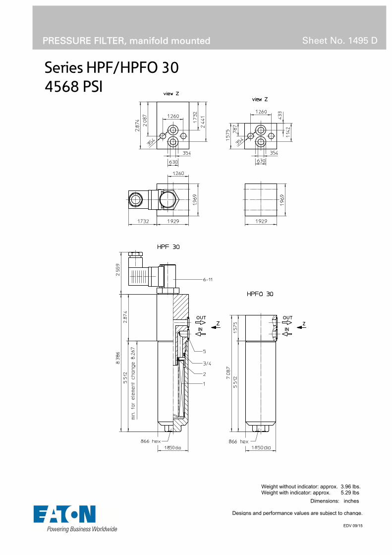
Series HPF/HPFO 30
4568 PSI
PRESSURE FILTER, manifold mounted
Sheet No. 1495 D
EDV 09/15
Weight without indicator: approx. 3.96 lbs. Weight with indicator: approx. 5.29 lbs
Dimensions: inches
Designs and performance values are subject to change.

Pressure Filter
Series HPF/HPFO 30
4568 PSI
Description: Pressure filter series HPF 30 and HPFO 30, have a working pressure up to 4568 PSI. Pressure peaks can be absorbed with a sufficient safety margin. The filters are flange mounted to the hydraulic system.
The filter element consists of star-shaped, pleated filter material, which is supported on the inside by a perforated core tube and is bonded to the end caps with a high-quality adhesive. The flow direction is from outside to inside. Filter elements are available down to 5 µm(c). Finer filtration is available upon request.
Eaton filter elements are known for high intrinsic stability and an excellent filtration capability, a high dirt-retaining capacity and a long service life.
Eaton filter are suitable for all petroleum based fluids, HW-emulsions, most synthetic hydraulic fluids and lubrication oils.
Eaton filter elements are available up to a pressure resistance of p 2320 PSI and a rupture strength of p 3625 PSI.
1. Type index:
1.1. Complete filter: (ordering example)
HPF. 30. 10VG. HR. E. P. -. F. 2. -. AE1 2 3 4 5 6 7 8 9 10 11
1 series: HPF = medium pressure filter, manifold mounted with indicator HPFO = medium pressure filter, manifold mounted without indicator
2 nominal size: 30
3 filter-material and filter-fineness: 80G, 40G, 25G, 10G stainless steel wire mesh 25VG, 16VG, 10VG, 6VG, 3VG microglass
4 filter element collapse rating: 30 = p 435 PSI HR = p 2320 PSI (rupture strength p 3625 PSI)
5 filter element design: E = single-end open
6 sealing material: P = Nitrile (NBR) V = Viton (FPM)
7 filter element specification: (see catalog) - = standard VA = stainless steel IS06 = for HFC application, see sheet-no. 31601
8 process connection: F = manifold mounted
9 process connection size: 2 = 3/8“
10 filter housing specification: (see catalog) - = standard IS06 = for HFC applications, see sheet-no. 31605
11 clogging indicator or clogging sensor: series HPFO: - = without series HPF: AOR = visual, see sheet-no. 1606 AOC = visual, see sheet-no. 1606 AE = visual-electric, see sheet-no. 1615 VS5 = electronic, see sheet-no. 1619
To add an indicator to your filter, use the corresponding indicator data sheet to find the indicator details and add them to the filter assembly model code.
1.2. Filter element: (ordering example)
01E. 30. 10VG. HR. E. P. - 1 2 3 4 5 6 7
1 series: 01E. = filter element according to company standard
2 nominal size: 30
3 - 7 see type index-complete filter

Technical data:
design temperature: 14 °F to +212 °F operating temperature: 14 °F to +176 °F operating medium mineral oil, other media on request max. operating pressure: 4568 PSI test pressure: 6532 PSI process connection: manifold mounted housing material: C-steel sealing material: Nitrile (NBR) or Viton (FPM), other materials on request installation position: vertical volume tank: .02 Gal
Classified under the Pressure Equipment Directive 2014/68/EC for mineral oil (fluid group 2), Article 4, Para. 3. Classified under ATEX Directive 2014/34/EC according to specific application (see questionnaire sheet-no. 34279-4).
Pressure drop flow curves:
Filter calculation/sizing
The pressure drop of the assembly at a given flow rate Q is the sum of the housing ∆p and the element ∆p and is calculated as follows:
p assembly = p housing + p element p housing = (see p = f (Q) - characteristics)
p element (PSI) = .
³
For ease of calculation our Filter Selection tool is available online at www.eatonpowersource.com/calculators/filtration/
Material gradient coefficients (MSK) for filter elements
The material gradient coefficients in psi/gpm apply to mineral oil (HLP) with a density of 0.876 kg/dm³ and a kinematic viscosity of 139 SUS (30 mm²/s). The pressure drop changes proportionally to the change in kinematic viscosity and density.
HPF/HPFO VG G
3VG 6VG 10VG 16VG 25VG 25G 40G 80G
30 12.554 8.716 5.580 4.794 3.275 0.2539 0.2369 0.1623
∆p = f(Q) – characteristics according to ISO 3968
The pressure drop characteristics apply to mineral oil (HLP) with a density of 0.876 kg/dm³. The pressure drop changes proportionally to the density.

Symbols: without indicator with electric
indicator AE 30 and AE 40
with visual-electric indicator
AE 50 and AE 62
with visual-electric indicator
AE 70 and AE 80
with visual indicator
AOR/AOC
with electronic clogging sensor
VS5
Spare parts: item qty. designation dimension article-no.
1 1 filter element 01E.30… 2 1 O-ring 11 x 3 312603 (NBR) 312727 (FPM) 3 1 O-ring 32 x 2,5 306843 (NBR) 308268 (FPM) 4 1 support ring 37 x 2,1 x 1 305466 5 2 O-ring 12 x 2 311014 (NBR) 310271 (FPM) 6 1 clogging indicator, visual AOR or AOC see sheet-no. 1606 7 1 clogging indicator, visual-electric AE see sheet-no. 1615 8 1 clogging sensor, electronic VS5 see sheet-no. 1619 9 1 O-ring 15 x 1,5 315357 (NBR) 315427 (FPM)
10 1 O-ring 22 x 2 304708 (NBR) 304721 (FPM) 11 1 O-ring 14 x 2 304342 (NBR) 304722 (FPM)
Test methods: Filter elements are tested according to the following ISO standards:
ISO 2941 Verification of collapse/burst resistance ISO 2942 Verification of fabrication integrity ISO 2943 Verification of material compatibility with fluids ISO 3723 Method for end load test ISO 3724 Verification of flow fatigue characteristics ISO 3968 Evaluation of pressure drop versus flow characteristics ISO 16889 Multi-pass method for evaluating filtration performance
North America 44 Apple Street Tinton Falls, NJ 07724
Toll Free: 800 656-3344 (North America only)
Tel: +1 732 212-4700 Europe/Africa/Middle East Auf der Heide 2 53947 Nettersheim, Germany
Tel: +49 2486 809-0
Friedensstraße 41 68804 Altlußheim, Germany
Tel: +49 6205 2094-0
An den Nahewiesen 24 55450 Langenlonsheim, Germany
Tel: +49 6704 204-0
China No. 3, Lane 280, Linhong Road Changning District, 200335 Shanghai, P.R. China
Tel: +86 21 5200-0099 Singapore 4 Loyang Lane #04-01/02 Singapore 508914
Tel: +65 6825-1668 Brazil Av. Julia Gaioli, 474 – Bonsucesso 07251-500 – Guarulhos, Brazil
Tel: +55 11 2465-8822
For more information, please email us at [email protected]
or visit www.eaton.com/filtration
© 2015 Eaton. All rights reserved. All trademarks and registered trademarks are the property of their respective owners. All information and recommendations appearing in this brochure concerning the use of products described herein are based on tests believed to be reliable. However, it is the user’s responsibility to determine the suitability for his own use of such products. Since the actual use by others is beyond our control, no guarantee, expressed or implied, is made by Eaton as to the effects of such use or the results to be obtained. Eaton assumes no liability arising out of the use by others of such products. Nor is the information herein to be construed as absolutely complete, since additional information may be necessary or desirable when particular or exceptional conditions or circumstances exist or because of applicable laws or government regulations.

Series HPP 60-450
4568 PSI
PRESSURE FILTER, manifold mounted
Sheet No. 1471 R
EDV 09/15
1) Connect the stand grounding tab to a suitable earth ground point.
Dimensions: inches Designs and performance values are subject to change.
Dimensions:
type HPP 60
HPP 90
HPP 150
HPP 170
HPP 240
HPP 360
HPP 450
connection ¾“ 1“ A 7.95 10.51 14.80 11.22 13.18 16.33 20.55 B 3.15 3.15 3.15 3.74 3.74 3.74 3.74 C 10.63 13.19 17.52 13.78 15.75 18.90 23.03 D .79 .79 .79 .87 .87 .87 .87 E 1.10 1.10 1.10 1.18 1.18 1.18 1.18 F 2.56 2.56 2.56 3.54 3.54 3.54 3.54
weight 11 lbs. 12 lbs. 14lbs. 33 lbs. 35 lbs. 39 lbs. 44 lbs. volume tank .08 Gal. .10 Gal. .16 Gal. .18 Gal. .23 Gal. .31 Gal. .42 Gal.

Pressure Filter
Series HPP 60-450
4568 PSI
Description: Pressure filter series HPP 60-450 have a working pressure up to 4568 PSI. Pressure peaks can be absorbed with a sufficient safety margin. The HPF-filters are flanged to the mounting-surface.
The filter element consists of star-shaped, pleated filter material, which is supported on the inside by a perforated core tube and is bonded to the end caps with a high-quality adhesive. The flow direction is from outside to inside. Filter elements are available down to 5 µm(c). Finer filtration is available upon request.
Eaton filter elements are known for high intrinsic stability and an excellent filtration capability, a high dirt-retaining capacity and a long service life.
Eaton filter elements are suitable for all petroleum based fluids, HW-emulsions, most synthetic hydraulic fluids and lubrication oils.
Eaton filter elements are available up to a pressure resistance of p 2320 PSI and a rupture strength ofp 3625 PSI.
The internal valve is integrated into the filter head. After reaching the bypass pressure setting, the bypass valve will send unfiltered partial flow around the filter.
The reversing valve provides another level of protection for the filter element. The reverse flow will not be filtered.
1. Type index:
1.1. Complete filter: (ordering example)
HPP. 90. 10VG. HR. E. P. -. P. 4. -. -. AE1 2 3 4 5 6 7 8 9 10 11 12
1 series: HPP = pressure filter, manifold mounted
2 nominal size: 60, 90, 150, 170, 240, 360, 450
3 filter-material and filter-fineness: 80G, 40G, 25G, 10G stainless steel wire mesh 25VG, 16VG, 10VG, 6VG, 3VG microglass
4 filter element collapse rating: 30 = p 435 PSI HR = p 2320 PSI (rupture strength p 3625 PSI)
5 filter element design: E = single-end open
6 sealing material: P = Nitrile (NBR) V = Viton (FPM)
7 filter element specification: (see catalog) - = standard VA = stainless steel IS06 = for HFC applications, see sheet-no. 31601
8 process connection: P = manifold mounted
9 process connection size: 4 = ¾“ (HPP 60-150) 5 = 1“ (HPP 170-450)
10 filter housing specification: (see catalog) - = standard IS06 = for HFC applications, see sheet no.31605
11 internal valve: - = without S1 = with bypass valve p 51 PSI S2 = with bypass valve p 102 PSI R = reversing valve, Q ≤ 18.50 GPM (HPP 60-150) reversing valve, Q ≤ 55.75 GPM (HPP 170-450)
12 clogging indicator or clogging sensor: - = without AOR = visual, see sheet-no. 1606 AOC = visual, see sheet-no. 1606 AE = visual-electric, see sheet-no. 1615 VS5 = electronic, see sheet-no. 1619
To add an indicator to your filter, use the corresponding indicator data sheet to find the indicator details and add them to the filter assembly model code.
1.2. Filter element: (ordering example)
01E. 90. 10VG. HR. E. P. - 1 2 3 4 5 6 7
1 series: 01E. = filter element according to company standard
2 nominal size: 60, 90, 150, 170, 240, 360, 450
3 - 7 see type index-complete filter

Technical data:
design temperature: 14 °F to +212 °F operating temperature: 14 °F to +176 °F operating medium mineral oil, other media on request max. operating pressure: 4568 PSI test pressure: 6525 PSI process connection: manifold mounted housing material: C-steel sealing material: Nitrile (NBR) or Viton (FPM), other materials on request installation position: vertical
Classified under the Pressure Equipment Directive 2014/68/EC for mineral oil (fluid group 2), Article 4, Para. 3. Classified under ATEX Directive 2014/34/EC according to specific application (see questionnaire sheet-no. 34279-4)
Pressure drop flow curves:
Filter calculation/sizing
The pressure drop of the assembly at a given flow rate Q is the sum of the housing ∆p and the element ∆p and is calculated as follows:
p assembly = p housing + p element p housing = (see p = f (Q) - characteristics)
p element (PSI) = .
³
For ease of calculation our Filter Selection tool is available online at www.eatonpowersource.com/calculators/filtration/
Material gradient coefficients (MSK) for filter elements
The material gradient coefficients in PSI/GPM apply to mineral oil (HLP) with a density of 0.876 kg/dm³ and a kinematic viscosity of 139 SUS (30 mm²/s). The pressure drop changes proportionally to the change in kinematic viscosity and density.
HPP VG G
3VG 6VG 10VG 16VG 25VG 25G 40G 80G
60 6.748 4.685 2.999 2.577 1.760 0.2002 0.1868 0.1280
90 4.059 2.818 1.804 1.550 1.059 0.1210 0.1130 0.0774
150 2.422 1.681 1.076 0.925 0.632 0.0723 0.0675 0.0462
170 2.714 1.884 1.206 1.036 0.708 0.0839 0.0783 0.0537
240 2.092 1.452 0.930 0.799 0.546 0.0651 0.0607 0.0416
360 1.530 1.062 0.680 0.584 0.399 0.0475 0.0444 0.0304
450 1.126 0.782 0.500 0.430 0.294 0.0349 0.0326 0.0223
∆p = f(Q) – characteristics according to ISO 3968
The pressure drop characteristics apply to mineral oil (HLP) with a density of 0.876 kg/dm³. The pressure drop changes proportionally to the density.

Symbols: without indicator with electric
indicator AE 30 and AE 40
with visual-electric indicator
AE 50 and AE 62
with visual-electric indicator
AE 70 and AE 80
with visual indicator
AOR/AOC
with electronic clogging sensor
VS5 filter without internal valve
filter with by-pass valve
filter with reversing valve
Spare parts:
item qty. designation dimension and article-no. HPP 60-150 HPF 170-450
1 1 filter element 01E.60… - 01E.150… 01E.170… - 01E.450… 2 1 O-Ring 22 x 3,5 304341 (NBR)
304392 (FPM) 34 x 3,5 304338 (NBR)
304730 (FPM) 3 1 O-Ring 54 x 3 304657 (NBR)
304720 (FPM) 75 x 3 302215 (NBR)
304729 (FPM) 4 1 support ring 61 x 2,6 x 1 304660 81 x 2,6 x 1 304581 5 2 O-Ring 22 x 3 304387 (NBR)
304931 (FPM) 33,3 x 2,4 304380 (NBR)
314706 (FPM) 6 1 clogging indicator, visual AOR or AOC see sheet-no. 1606 7 1 clogging indicator, visual-electric AE see sheet-no. 1615 8 1 clogging sensor, electronic VS5 see sheet-no. 1619 9 1 O-Ring 15 x 1,5
315357 (NBR) 315427 (FPM)
10 1 O-Ring 22 x 2
304708 (NBR) 304721 (FPM)
11 1 O-Ring 14 x 2
304342 (NBR) 304722 (FPM)
12 1 srew plug 20913-4 309817
item 12 execution only without clogging indicator or clogging sensor
Test methods: Filter elements are tested according to the following ISO standards:
ISO 2941 Verification of collapse/burst resistance ISO 2942 Verification of fabrication integrity ISO 2943 Verification of material compatibility with fluids ISO 3723 Method for end load test ISO 3724 Verification of flow fatigue characteristics ISO 3968 Evaluation of pressure drop versus flow characteristics ISO 16889 Multi-pass method for evaluating filtration performance
North America 44 Apple Street Tinton Falls, NJ 07724
Toll Free: 800 656-3344 (North America only)
Tel: +1 732 212-4700 Europe/Africa/Middle East Auf der Heide 2 53947 Nettersheim, Germany
Tel: +49 2486 809-0
Friedensstraße 41 68804 Altlußheim, Germany
Tel: +49 6205 2094-0
An den Nahewiesen 24 55450 Langenlonsheim, Germany
Tel: +49 6704 204-0
China No. 3, Lane 280, Linhong Road Changning District, 200335 Shanghai, P.R. China
Tel: +86 21 5200-0099 Singapore 4 Loyang Lane #04-01/02 Singapore 508914
Tel: +65 6825-1668 Brazil Av. Julia Gaioli, 474 – Bonsucesso 07251-500 – Guarulhos, Brazil
Tel: +55 11 2465-8822
For more information, please email us at [email protected]
or visit www.eaton.com/filtration
© 2015 Eaton. All rights reserved. All trademarks and registered trademarks are the property of their respective owners. All information and recommendations appearing in this brochure concerning the use of products described herein are based on tests believed to be reliable. However, it is the user’s responsibility to determine the suitability for his own use of such products. Since the actual use by others is beyond our control, no guarantee, expressed or implied, is made by Eaton as to the effects of such use or the results to be obtained. Eaton assumes no liability arising out of the use by others of such products. Nor is the information herein to be construed as absolutely complete, since additional information may be necessary or desirable when particular or exceptional conditions or circumstances exist or because of applicable laws or government regulations.

Series HPP 601-1351
4568 PSI
PRESSURE FILTER, manifold mounted
Sheet No. 1470 N
EDV 09/15
1) Connect the stand grounding tab to a suitable earth ground point.
Dimensions: inches Designs and performance values are subject to change.
Dimensions:
type HPP 601 HPP 901 HPP 1351 connection 1 ¼“ 1 ¼“ 1 ¼“
A 19.17 25.07 34.84 B 12.20 18.11 27.95
weight 86 lbs. 101 lbs. 128 lbs. volume tank .55 Gal. .82 Gal. 1.21 Gal.

Pressure Filter
Series HPP 601-1351
4568 PSI
Description: Pressure filter series HPP 601-1351 have a working pressure up to 4568 PSI. Pressure peaks can be absorbed with a sufficient safety margin. The HPP-filters are flanged to the mounting-surface.
The filter element consists of star-shaped, pleated filter material, which is supported on the inside by a perforated core tube and is bonded to the end caps with a high-quality adhesive. The flow direction is from outside to inside. Filter elements are available down to 5 µm(c). Finer filtration is available upon request.
Eaton filter elements are known for high intrinsic stability and an excellent filtration capability, a high dirt-retaining capacity and a long service life.
Eaton filter elements are suitable for all petroleum based fluids, HW-emulsions, most synthetic hydraulic fluids and lubrication oils.
Eaton filter elements are available up to a pressure resistance of p 2320 PSI and a rupture strength ofp 3625 PSI.
The internal valve is integrated into the filter head. After reaching the bypass pressure setting, the bypass valve will send unfiltered partial flow around the filter.
The reversing valve provides another level of protection for the filter element. The reverse flow will not be filtered.
1. Type index:
1.1. Complete filter: (ordering example)
HPP.901.10VG. HR. E. P. -. P. 6. -. -. AE1 2 3 4 5 6 7 8 9 10 11 12
1 series: HPP = pressure filter, manifold mounted
2 nominal size: 601, 901, 1351
3 filter-material and filter-fineness: 80G, 40G, 25G, 10G stainless steel wire mesh 25VG, 16VG, 10VG, 6VG, 3VG microglass
4 filter element collapse rating: 30 = p 435 PSI HR = p 2320 PSI (rupture strength p 3625 PSI)
5 filter element design: E = single-end open
6 sealing material: P = Nitrile (NBR) V = Viton (FPM)
7 filter element specification: (see catalog) - = standard VA = stainless steel IS06 = for HFC applications, see sheet-no. 31601
8 process connection: P = manifold mounted
9 process connection size: 6 = 1 ¼“
10 filter housing specification: (see catalog) - = standard IS06 = for HFC applications, see sheet no.31605
11 internal valve: - = without S1 = with bypass valve p 51 PSI S2 = with bypass valve p 102 PSI R = reversing valve, Q ≤ 122.94 GPM
12 clogging indicator or clogging sensor: - = without AOR = visual, see sheet-no. 1606 AOC = visual, see sheet-no. 1606 AE = visual-electric, see sheet-no. 1615 VS5 = electronic, see sheet-no. 1619
To add an indicator to your filter, use the corresponding indicator data sheet to find the indicator details and add them to the filter assembly model code.
1.2. Filter element: (ordering example)
01E. 900. 10VG. HR. E. P. - 1 2 3 4 5 6 7
1 series: 01E. = filter element according to company standard
2 nominal size: 600, 900, 1350
3 - 7 see type index-complete filter

Technical data:
design temperature: 14 °F to +212 °F operating temperature: 14 °F to +176 °F operating medium mineral oil, other media on request max. operating pressure: 4568 PSI test pressure: 6525 PSI process connection: manifold mounted housing material: C-steel, EN-GJS-400-18-LT sealing material: Nitrile (NBR) or Viton (FPM), other materials on request installation position: vertical
Classified under the Pressure Equipment Directive 2014/68/EC for mineral oil (fluid group 2), Article 4, Para. 3. Classified under ATEX Directive 2014/34/EC according to specific application (see questionnaire sheet-no. 34279-4)
Pressure drop flow curves:
Filter calculation/sizing
The pressure drop of the assembly at a given flow rate Q is the sum of the housing ∆p and the element ∆p and is calculated as follows:
p assembly = p housing + p element p housing = (see p = f (Q) - characteristics)
p element (PSI) = .
³
For ease of calculation our Filter Selection tool is available online at www.eatonpowersource.com/calculators/filtration/
Material gradient coefficients (MSK) for filter elements
The material gradient coefficients in PSI/GPM apply to mineral oil (HLP) with a density of 0.876 kg/dm³ and a kinematic viscosity of 139 SUS (30 mm²/s). The pressure drop changes proportionally to the change in kinematic viscosity and density.
HPP VG G
3VG 6VG 10VG 16VG 25VG 25G 40G 80G
601 0.963 0.669 0.428 0.368 0.251 0.0303 0.0282 0.0193
901 0.668 0.464 0.297 0.225 0.174 0.0189 0.0177 0.0121
1351 0.417 0.290 0.185 0.185 0.109 0.0122 0.0114 0.0078
∆p = f(Q) – characteristics according to ISO 3968
The pressure drop characteristics apply to mineral oil (HLP) with a density of 0.876 kg/dm³. The pressure drop changes proportionally to the density.

Symbols: without indicator with electric
indicator AE 30 and AE 40
with visual-electric indicator
AE 50 and AE 62
with visual-electric indicator
AE 70 and AE 80
with visual indicator
AOR/AOC
with electronic clogging sensor
VS5
filter without internal valve
filter with by-pass valve
filter with reversing valve
Spare parts:
item qty. designation dimension article-no. HPP 601 HPP 901 HPP 1351
1 1 filer element 01E.600… 01E.900… 01E.1350… 2 1 O-ring 48 x 3 304357 (NBR) 304404 (FPM) 3 1 O-ring 98 x 4 301914 (NBR) 304765 (FPM) 4 1 support ring 110 x 3,5 x 2 304802 5 2 O-ring 34 x 3,5 304338 NBR) 304730 (FPM) 6 1 clogging indicator, visual AOR or AOC see sheet-no. 1606 7 1 clogging indicator, visual-electric AE see sheet-no. 1615 8 1 clogging sensor, electronic VS5 see sheet-no. 1619 9 1 O-ring 15 x 1,5 315357 (NBR) 315427 (FPM)
10 1 O-ring 22 x 2 304708 (NBR) 304721 (FPM) 11 1 O-ring 14 x 2 304342 (NBR) 304722 (FPM) 12 1 screw plug 20913-4 309817 13 1 screw plug ½ BSPP 304678
item 12 execution only without clogging indicator or clogging sensor
Test methods: Filter elements are tested according to the following ISO standards:
ISO 2941 Verification of collapse/burst resistance ISO 2942 Verification of fabrication integrity ISO 2943 Verification of material compatibility with fluids ISO 3723 Method for end load test ISO 3724 Verification of flow fatigue characteristics ISO 3968 Evaluation of pressure drop versus flow characteristics ISO 16889 Multi-pass method for evaluating filtration performance
North America 44 Apple Street Tinton Falls, NJ 07724
Toll Free: 800 656-3344 (North America only)
Tel: +1 732 212-4700 Europe/Africa/Middle East Auf der Heide 2 53947 Nettersheim, Germany
Tel: +49 2486 809-0
Friedensstraße 41 68804 Altlußheim, Germany
Tel: +49 6205 2094-0
An den Nahewiesen 24 55450 Langenlonsheim, Germany
Tel: +49 6704 204-0
China No. 3, Lane 280, Linhong Road Changning District, 200335 Shanghai, P.R. China
Tel: +86 21 5200-0099 Singapore 4 Loyang Lane #04-01/02 Singapore 508914
Tel: +65 6825-1668 Brazil Av. Julia Gaioli, 474 – Bonsucesso 07251-500 – Guarulhos, Brazil
Tel: +55 11 2465-8822
For more information, please email us at [email protected]
or visit www.eaton.com/filtration
© 2015 Eaton. All rights reserved. All trademarks and registered trademarks are the property of their respective owners. All information and recommendations appearing in this brochure concerning the use of products described herein are based on tests believed to be reliable. However, it is the user’s responsibility to determine the suitability for his own use of such products. Since the actual use by others is beyond our control, no guarantee, expressed or implied, is made by Eaton as to the effects of such use or the results to be obtained. Eaton assumes no liability arising out of the use by others of such products. Nor is the information herein to be construed as absolutely complete, since additional information may be necessary or desirable when particular or exceptional conditions or circumstances exist or because of applicable laws or government regulations.

Series HPU 601-1351
4568 PSI
PRESSURE FILTER, manifold mounted
Sheet No. 1480 H
EDV 09/15
Dimensions: inches Designs and performance values are subject to change.
Dimensions:
type HPU 601 HPU 901 HPU 1351 connection 1 ¼“
A 21.14 27.05 36.81 B 12.20 18.11 27.95
weight 83 lbs. 101 lbs. 130 lbs. volume tank .55 Gal. .82 Gal. 1.21 Gal.

Pressure Filter
Series HPU 601-1351
4568 PSI
Description: Pressure filter series HPU 601-1351 have a working pressure up to 4568 PSI. Pressure peaks can be absorbed with a sufficient safety margin. The HPU-filters are flange mounted to the hydraulic system. The filter element consists of star-shaped, pleated filter material, which is supported on the inside by a perforated core tube and is bonded to the end caps with a high-quality adhesive. The flow direction is from outside to inside. Filter elements are available down to 4 µm(c).
Eaton filter elements are known for high intrinsic stability and an excellent filtration capability, a high dirt-retaining capacity and a long service life.
Eaton filter elements can be used for petroleum-based fluids, HW emulsions, water glycols, most synthetic fluids and lubrication fluids. Consult factory for specific fluid applications.
Eaton filter elements are available up to a pressure resistance of p 2320 PSI and a rupture strength ofp 3625 PSI.
The internal valve is integrated into the filter head. After reaching the bypass pressure setting, the bypass valve will send unfiltered partial flow around the filter.
The reversing valve provides another level of protection for the filter element. The reverse flow will not be filtered.
1. Type index:
1.1. Complete filter: (ordering example)
HPU. 901. 10VG. HR. E. P. -. P. 6. -. -. AE. -1 2 3 4 5 6 7 8 9 10 11 12 13
1 series: HPU = pressure filter, manifold mounted
2 nominal size: 601, 901, 1351
3 filter-material and filter-fineness: 80G, 40G, 25G, 10G stainless steel wire mesh 25VG, 16VG, 10VG, 6VG, 3VG microglass
4 filter element collapse rating: 30 = p 435 PSI HR = p 2320 PSI (rupture strength p 3625 PSI)
5 filter element design: E = single-end open
6 sealing material: P = Nitrile (NBR) V = Viton (FPM)
7 filter element specification: (see catalog) - = standard VA = stainless steel IS06 = for HFC applications, see sheet-no. 31601
8 process connection: P = manifold mounted
9 process connection size: 6 = 1 ¼“
10 filter housing specification: (see catalog) - = standard IS06 = for HFC applications, see sheet-no. 31605
11 internal valve: - = without S1 = with bypass valve p 51 PSI S2 = with bypass valve p 102 PSI R = reversing valve, Q ≤ 122.94 GPM
12 clogging indicator or clogging sensor at M1: - = without AOR = visual, see sheet-no. 1606 AOC = visual, see sheet-no. 1606 AE = visual-electric, see sheet-no. 1615 VS5 = electronic, see sheet-no. 1619
13 clogging indicator or clogging sensor at M1: possible indicators see position 12 of the type index
To add an indicator to your filter, use the corresponding indicator data sheet to find the indicator details and add them to the filter assembly model code.
1.2. Filter element: (ordering example)
01E. 900. 10VG. HR. E. P. - 1 2 3 4 5 6 7
1 series: 01E. = filter element according to company standard
2 nominal size: 600, 900, 1350
3 - 7 see type index-complete filter

Technical data:
design temperature: 14 °F to +212 °F operating temperature: 14 °F to +176 °F operating medium mineral oil, other media on request max. operating pressure: 4568 PSI test pressure: 6532 PSI process connection: manifold mounted housing material: EN-GJS-400-18-LT, C-steel sealing material: Nitrile (NBR) or Viton (FPM), other materials on request installation position: vertical
Classified under the Pressure Equipment Directive 2014/68/EC for mineral oil (fluid group 2), Article 4, Para. 3. Classified under ATEX Directive 2014/34/EC according to specific application (see questionnaire sheet-no. 34279-4).
Pressure drop flow curves:
Filter calculation/sizing
The pressure drop of the assembly at a given flow rate Q is the sum of the housing ∆p and the element ∆p and is calculated as follows:
p assembly = p housing + p element p housing = (see p = f (Q) - characteristics)
p element (PSI) = .
³
For ease of calculation our Filter Selection tool is available online at www.eatonpowersource.com/calculators/filtration/
Material gradient coefficients (MSK) for filter elements
The material gradient coefficients in PSI/GPM apply to mineral oil (HLP) with a density of 0.876 kg/dm³ and a kinematic viscosity of 139 SUS (30 mm²/s). The pressure drop changes proportionally to the change in kinematic viscosity and density.
HPU VG G
3VG 6VG 10VG 16VG 25VG 25G 40G 80G
601 0.963 0.669 0.428 0.368 0.251 0.0303 0.0282 0.0193
901 0.668 0.464 0.297 0.225 0.174 0.0189 0.0177 0.0121
1351 0.417 0.290 0.185 0.185 0.109 0.0122 0.0114 0.0078
∆p = f(Q) – characteristics according to ISO 3968
The pressure drop characteristics apply to mineral oil (HLP) with a density of 0.876 kg/dm³. The pressure drop changes proportionally to the density.

Symbols:
without indicator with electric indicator
AE 30 and AE 40
with visual-electric indicator
AE 50 and AE 62
with visual-electric indicator
AE 70 and AE 80
with visual indicator
AOR/AOC
with electronic clogging sensor
VS5 filter without internal valve
filter with by-pass valve
filter with reversing valve
Spare parts:
item qty. designation dimension article-no. HPU 601 HPU 901 HPU 1351
1 1 filer element 01E.600… 01E.900… 01E.1350… 2 1 O-ring 48 x 3 304357 (NBR) 304404 (FPM) 3 1 O-ring 98 x 4 301914 (NBR) 304765 (FPM) 4 1 support ring 110 x 3,5 x 2 304802 5 2 O-ring 34 x 3,5 304338 (NBR) 304730 (FPM) 6 1 clogging indicator, visual AOR or AOC see sheet no. 1606 7 1 clogging indicator, visual-electric AE see sheet no. 1615 8 1 clogging sensor, electronic VS5 see sheet no. 1619 9 1 O-ring 15 x 1,5 315357 (NBR) 315427 (FPM)
10 1 O-ring 22 x 2 304708 (NBR) 304721 (FPM) 11 1 O-ring 14 x 2 304342 (NBR) 304722 (FPM) 12 1 screw plug 20913-4 309817 13 1 screw plug ½ BSPP 304678
item 12 execution only without clogging indicator or clogging sensor
Test methods: Filter elements are tested according to the following ISO standards:
ISO 2941 Verification of collapse/burst resistance ISO 2942 Verification of fabrication integrity ISO 2943 Verification of material compatibility with fluids ISO 3723 Method for end load test ISO 3724 Verification of flow fatigue characteristics ISO 3968 Evaluation of pressure drop versus flow characteristics ISO 16889 Multi-pass method for evaluating filtration performance
North America 44 Apple Street Tinton Falls, NJ 07724
Toll Free: 800 656-3344 (North America only)
Tel: +1 732 212-4700 Europe/Africa/Middle East Auf der Heide 2 53947 Nettersheim, Germany
Tel: +49 2486 809-0
Friedensstraße 41 68804 Altlußheim, Germany
Tel: +49 6205 2094-0
An den Nahewiesen 24 55450 Langenlonsheim, Germany
Tel: +49 6704 204-0
China No. 3, Lane 280, Linhong Road Changning District, 200335 Shanghai, P.R. China
Tel: +86 21 5200-0099 Singapore 4 Loyang Lane #04-01/02 Singapore 508914
Tel: +65 6825-1668 Brazil Av. Julia Gaioli, 474 – Bonsucesso 07251-500 – Guarulhos, Brazil
Tel: +55 11 2465-8822
For more information, please email us at [email protected]
or visit www.eaton.com/filtration
© 2015 Eaton. All rights reserved. All trademarks and registered trademarks are the property of their respective owners. All information and recommendations appearing in this brochure concerning the use of products described herein are based on tests believed to be reliable. However, it is the user’s responsibility to determine the suitability for his own use of such products. Since the actual use by others is beyond our control, no guarantee, expressed or implied, is made by Eaton as to the effects of such use or the results to be obtained. Eaton assumes no liability arising out of the use by others of such products. Nor is the information herein to be construed as absolutely complete, since additional information may be necessary or desirable when particular or exceptional conditions or circumstances exist or because of applicable laws or government regulations.

Series HPW 60-450
4568 PSI
PRESSURE FILTER, bidirectional filtration
Sheet No. 1481 N
EDV 09/15
Dimensions: inches Designs and performance values are subject to change.
Dimensions: type HPW 60 HPW 90 HPW 150
A 9.72 12.28 16.58 B 3.54 3.54 3.54 C 10.63 13.19 17.52 D -16 SAE -16 SAE -16 SAE E 1.38 1.38 1.38 F 2.56 2.56 2.56 G .48 .48 .48 H 1.97 1.97 1.97 J 3.35 3.35 3.35 K 7.87 7.87 7.87
weight 35.2 lbs. 36.3 lbs. 37.4 lbs. volume tank .08 Gal. .10 Gal. .16 Gal.
type HPW 170 HPW 240 HPW 360 HPW 450
A 13.78 15.75 18.90 23.03 B 4.72 4.72 4.72 4.72 C 13.80 15.75 18.90 13.03 D -24 SAE -24 SAE -24 SAE -24 SAE E 1.58 1.58 1.58 1.58 F 3.55 3.55 3.55 3.55 G .55 .55 .55 .55 H 2.36 2.36 2.36 2.36 J 4.53 4.53 4.53 4.53 K 10.63 10.63 10.63 10.63
weight 85.8 lbs. 88.0 lbs. 92.4 lbs. 96.8 lbs. volume tank .18 Gal. .23 Gal. .31 Gal. .42 Gal.
1) Connect the stand grounding tab to a suitable earth ground point.

Pressure Filter
Series HPW 60-450
4568 PSI
Description: Pressure filter series HPW 60-450 are used in systems where the fluid requires bidirectional flow through the same filter. A series of four internal check valves ensure that the system fluid is directed to the outside of the element, regardless of flow direction.
The filter element consists of star-shaped, pleated filter material, which is supported on the inside by a perforated core tube and is bonded to the end caps with a high-quality adhesive. The flow direction is from outside to inside. Filter elements are available down to 4 µm(c).
Eaton filter elements are known for high intrinsic stability and an excellent filtration capability, a high dirt-retaining capacity and a long service life.
Eaton filter elements can be used for petroleum-based fluids, HW emulsions, water glycols, most synthetic fluids and lubrication fluids. Consult factory for specific fluid applications.
Eaton filter elements are available up to a pressure resistance of p 2320 PSI and a rupture strength ofp 3625 PSI.
The internal valve is integrated into the filter head. After reaching the bypass pressure setting, the bypass valve will send unfiltered partial flow around the filter.
1. Type index:
1.1. Complete filter: (ordering example)
HPW. 170. 10VG. HR. E. P. -. UG. 7. -. -. AE1 2 3 4 5 6 7 8 9 10 11 12
1 series: HPW = pressure filter for reversible filtration
2 nominal size: 60, 90, 150, 170, 240, 360, 450
3 filter-material and filter-fineness: 80G, 40G, 25G, 10G stainless steel wire mesh 25VG, 16VG, 10VG, 6VG, 3VG microglass
4 filter element collapse rating: 30 = p 435 PSI HR = p 2320 PSI (rupture strength p 3625 PSI)
5 filter element design: E = single-end open
6 sealing material: P = Nitrile (NBR) V = Viton (FPM)
7 filter element specification: - = standard VA = stainless steel
8 process connection: UG = thread connection
9 process connection size: 5 = -16 SAE HPW 60-150 7 = -24 SAE HPW 170-450
10 filter housing specification: - = standard
11 internal valve: - = without S1 = with bypass valve p 51 PSI S2 = with bypass valve p 102 PSI
12 clogging indicator or clogging sensor: - = without AOR = visual, see sheet-no. 1606 AOC = visual, see sheet-no. 1606 AE = visual-electric, see sheet-no. 1615 VS5 = electronic, see sheet-no. 1619
To add an indicator to your filter, use the corresponding indicator data sheet to find the indicator details and add them to the filter assembly model code.
1.2. Filter element: (ordering example)
01E. 170. 10VG. HR. E. P. - 1 2 3 4 5 6 7
1 series: 01E. = filter element according to company standard
2 nominal size: 60, 90, 150, 170, 240, 360, 450
3 - 7 see type index-complete filter

Technical data:
design temperature: 14 °F to +212 °F operating temperature: 14 °F to +176 °F operating medium mineral oil, other media on request max. operating pressure: 4568 PSI test pressure: 6532 PSI process connection: thread connection housing material: C-steel sealing material: Nitrile (NBR) or Viton (FPM), other materials on request installation position: vertical
Classified under the Pressure Equipment Directive 2014/68/EC for mineral oil (fluid group 2), Article 4, Para. 3. Classified under ATEX Directive 2014/34/EC according to specific application (see questionnaire sheet-no. 34279-4).
Pressure drop flow curves:
Filter calculation/sizing
The pressure drop of the assembly at a given flow rate Q is the sum of the housing ∆p and the element ∆p and is calculated as follows:
p assembly = p housing + p element p housing = (see p = f (Q) - characteristics)
p element (PSI) = .
³
For ease of calculation our Filter Selection tool is available online at www.eatonpowersource.com/calculators/filtration/
Material gradient coefficients (MSK) for filter elements
The material gradient coefficients in PSI/GPM apply to mineral oil (HLP) with a density of 0.876 kg/dm³ and a kinematic viscosity of 139 SUS (30 mm²/s). The pressure drop changes proportionally to the change in kinematic viscosity and density.
HPW VG G
3VG 6VG 10VG 16VG 25VG 25G 40G 80G
60 6.748 4.685 2.999 2.577 1.760 0.2002 0.1868 0.1280
90 4.059 2.818 1.804 1.550 1.059 0.1210 0.1130 0.0774
150 2.422 1.681 1.076 0.925 0.632 0.0723 0.0675 0.0462
170 2.714 1.884 1.206 1.036 0.708 0.0839 0.0783 0.0537
240 2.092 1.452 0.930 0.799 0.546 0.0651 0.0607 0.0416
360 1.530 1.062 0.680 0.584 0.399 0.0475 0.0444 0.0304
450 1.126 0.782 0.500 0.430 0.294 0.0349 0.0326 0.0223
∆p = f(Q) – characteristics according to ISO 3968
The pressure drop characteristics apply to mineral oil (HLP) with a density of 0.876 kg/dm³. The pressure drop changes proportionally to the density.

Symbols:
without indicator with electrical indicator
AE 30 and AE 40
with visual-electric indicator
AE 50 and AE 62
with visual-electricl indicator
AE 70 and AE 80
with visual indicator
AOR/AOC
with electronic clogging sensor
VS5 filter without internal valve
filter with by-pass valve
Spare parts:
item qty. designation dimension and article-no. HPW 60 HPW 90 HPW 150 HPW 170 HPW 240 HPW 360 HPW 450
1 1 filter element 01E.60… 01E.90… 01E.150…. 01E.170… 01E.240… 01E.360… 01E.450… 2 1 O-ring 22 x 3,5 304341 (NBR)
304392 (FPM) 34 x 3,5 304338 (NBR)
304730 (FPM) 3 1 O-ring 54 x 3 304657 (NBR)
304720 (FPM) 75 x 3 302215 (NBR)
304729 (FPM) 4 1 support ring 61 x 2,6 x 1 304660 81 x 2,6 x 1 304581 5 1 clogging indicator visual AOR or AOC see sheet-no. 1606 6 1 clogging indicator visual-electrical AE see sheet-no. 1615 7 1 clogging sensor electronical VS5 see sheet-no. 1619 /8 1 O-ring 15 x 1,5 315357 (NBR)
315427 (FPM) 9 1 O-ring 22 x 2 304708 (NBR)
304721 (FPM) 10 1 O-ring 14 x 2 304342 (NBR)
304722 (FPM) 11 1 screw plug 20913-4 309817
item 11 execution only without clogging indicator or clogging sensor
Test methods: Filter elements are tested according to the following ISO standards:
ISO 2941 Verification of collapse/burst resistance ISO 2942 Verification of fabrication integrity ISO 2943 Verification of material compatibility with fluids ISO 3723 Method for end load test ISO 3724 Verification of flow fatigue characteristics ISO 3968 Evaluation of pressure drop versus flow characteristics ISO 16889 Multi-pass method for evaluating filtration performance
North America 44 Apple Street Tinton Falls, NJ 07724
Toll Free: 800 656-3344 (North America only)
Tel: +1 732 212-4700 Europe/Africa/Middle East Auf der Heide 2 53947 Nettersheim, Germany
Tel: +49 2486 809-0
Friedensstraße 41 68804 Altlußheim, Germany
Tel: +49 6205 2094-0
An den Nahewiesen 24 55450 Langenlonsheim, Germany
Tel: +49 6704 204-0
China No. 3, Lane 280, Linhong Road Changning District, 200335 Shanghai, P.R. China
Tel: +86 21 5200-0099 Singapore 4 Loyang Lane #04-01/02 Singapore 508914
Tel: +65 6825-1668 Brazil Av. Julia Gaioli, 474 – Bonsucesso 07251-500 – Guarulhos, Brazil
Tel: +55 11 2465-8822
For more information, please email us at [email protected]
or visit www.eaton.com/filtration
© 2015 Eaton. All rights reserved. All trademarks and registered trademarks are the property of their respective owners. All information and recommendations appearing in this brochure concerning the use of products described herein are based on tests believed to be reliable. However, it is the user’s responsibility to determine the suitability for his own use of such products. Since the actual use by others is beyond our control, no guarantee, expressed or implied, is made by Eaton as to the effects of such use or the results to be obtained. Eaton assumes no liability arising out of the use by others of such products. Nor is the information herein to be construed as absolutely complete, since additional information may be necessary or desirable when particular or exceptional conditions or circumstances exist or because of applicable laws or government regulations.

Series HPW 601-1351
4568 PSI
PRESSURE FILTER, bidirectional filtration
Sheet No. 1482 K
EDV 09/15
Dimensions: inches Designs and performance values are subject to change.
Dimensions: type HPW 601 HPW 901 HPW 1351
connection 2“ A 23.70 29.60 39.37 B 12.20 18.11 27.95
weight 253 268 lbs. 295 lbs. volume tank .55 Gal. .82 Gal. 1.21 Gal.
1) Connect the stand grounding tab to a suitable earth ground point.

Pressure Filter
Series HPW 601-1351
4568 PSI
Description: Pressure filter series HPW 601-1351 are used in systems where the fluid requires bidirectional flow through the same filter. A series of four internal check valves ensure that the system fluid is directed to the outside of the element, regardless of flow direction.
The filter element consists of star-shaped, pleated filter material, which is supported on the inside by a perforated core tube and is bonded to the end caps with a high-quality adhesive. The flow direction is from outside to inside. Filter elements are available down to 4 µm(c).
Eaton filter elements are known for high intrinsic stability and an excellent filtration capability, a high dirt-retaining capacity and a long service life.
Eaton filter elements can be used for petroleum-based fluids, HW emulsions, water glycols, most synthetic fluids and lubrication fluids. Consult factory for specific fluid applications.
Eaton filter elements are available up to a pressure resistance of p 2320 PSI and a rupture strength ofp 3625 PSI.
The internal valve is integrated into the filter head. After reaching the bypass pressure setting, the bypass valve will send unfiltered partial flow around the filter.
1. Type index:
1.1. Complete filter: (ordering example)
HPW. 901. 10VG. HR. E. P. -. FW. 8. -. -. AE1 2 3 4 5 6 7 8 9 10 11 12
1 series: HPW = pressure filter for reversible filtration
2 nominal size: 601, 901, 1351
3 filter-material and filter-fineness: 80G, 40G, 25G, 10G stainless steel wire mesh 25VG, 16VG, 10VG, 6VG, 3VG microglass
4 filter element collapse rating: 30 = p 435 PSI HR = p 2320 PSI (rupture strength p 3625 PSI)
5 filter element design: E = single-end open
6 sealing material: P = Nitrile (NBR) V = Viton (FPM)
7 filter element specification: - = standard VA = stainless steel
8 process connection: FW = flange connection factory specification UG = thread connection
9 process connection size: 8 = 2“
10 filter housing specification: - = standard
11 internal valve: - = without S1 = with bypass valve p 51 PSI S2 = with bypass valve p 102 PSI
12 clogging indicator or clogging sensor: - = without AOR = visual, see sheet-no. 1606 AOC = visual, see sheet-no. 1606 AE = visual-electric, see sheet-no. 1615 VS5 = electronic, see sheet-no. 1619
To add an indicator to your filter, use the corresponding indicator data sheet to find the indicator details and add them to the filter assembly model code.
1.2. Filter element: (ordering example)
01E. 900. 10VG. HR. E. P. - 1 2 3 4 5 6 7
1 series: 01E. = filter element according to company standard
2 nominal size: 600, 900, 1350
3 - 7 see type index-complete filter
Accessories: - counter flange, see sheet-no. 1654

Technical data:
design temperature: 14 °F to +212 °F operating temperature: 14 °F to +176 °F operating medium mineral oil, other media on request max. operating pressure: 4568 PSI test pressure: 6532 PSI process connection: flange connection factory specification or thread connection housing material: C-steel , EN-GJS-400-18-LT sealing material: Nitrile (NBR) or Viton (FPM), other materials on request installation position: vertical
Classified under the Pressure Equipment Directive 2014/68/EC for mineral oil (fluid group 2), Article 4, Para. 3. Classified under ATEX Directive 2014/34/EC according to specific application (see questionnaire sheet-no. 34279-4).
Pressure drop flow curves:
Filter calculation/sizing
The pressure drop of the assembly at a given flow rate Q is the sum of the housing ∆p and the element ∆p and is calculated as follows:
p assembly = p housing + p element p housing = (see p = f (Q) - characteristics)
p element (PSI) = .
³
For ease of calculation our Filter Selection tool is available online at www.eatonpowersource.com/calculators/filtration/
Material gradient coefficients (MSK) for filter elements
The material gradient coefficients in PSI/GPM apply to mineral oil (HLP) with a density of 0.876 kg/dm³ and a kinematic viscosity of 139 SUS (30 mm²/s). The pressure drop changes proportionally to the change in kinematic viscosity and density.
HPW VG G
3VG 6VG 10VG 16VG 25VG 25G 40G 80G
601 0.963 0.669 0.428 0.368 0.251 0.0303 0.0282 0.0193
901 0.668 0.464 0.297 0.225 0.174 0.0189 0.0177 0.0121
1351 0.417 0.290 0.185 0.185 0.109 0.0122 0.0114 0.0078
∆p = f(Q) – characteristics according to ISO 3968
The pressure drop characteristics apply to mineral oil (HLP) with a density of 0.876 kg/dm³. The pressure drop changes proportionally to the density.

Symbols:
without indicator with electrical indicator
AE 30 and AE 40
with visual-electric indicator
AE 50 and AE 62
with visual-electricl indicator
AE 70 and AE 80
with visual indicator
AOR/AOC
with electronic clogging sensor
VS5 filter without internal valve
filter with by-pass valve
Spare parts:
item qty. designation dimension article-no.. HPW 601 HPW 901 HPW 1351
1 1 filter element 01E.600… 01E.900… 01E.1350… 2 1 O-ring 48 x 3 304357 (NBR) 304404 (FPM) 3 1 O-ring 98 x 4 301914 (NBR) 304765 (FPM) 4 1 support ring 110 x 3,5 x 2 304802 5 2 counter flange FW 50-4-2.99 x .49 303717.1 6 2 adapter FW.8.UG.8 320556 7 2 O-ring 68 x 5 304376 (NBR) 304394 (FPM) 8 1 clogging indicator visual AOR or AOC see sheet-no. 1606 9 1 clogging indicator visual-electric AE see sheet-no. 1615
10 1 clogging sensor electronic VS5 see sheet-no. 1619 11 1 O-ring 15 x 1,5 315357 (NBR) 315427 (FPM) 12 1 O-ring 22 x 2 304708 (NBR) 304721 (FPM) 13 1 O-ring 14 x 2 304342 (NBR) 304722 (FPM) 14 1 screw plug 20913-4 309817 15 1 screw plug ½ BSPP 304678
item 14 execution only without clogging indicator or clogging sensor
Test methods: Filter elements are tested according to the following ISO standards:
ISO 2941 Verification of collapse/burst resistance ISO 2942 Verification of fabrication integrity ISO 2943 Verification of material compatibility with fluids ISO 3723 Method for end load test ISO 3724 Verification of flow fatigue characteristics ISO 3968 Evaluation of pressure drop versus flow characteristics ISO 16889 Multi-pass method for evaluating filtration performance
North America 44 Apple Street Tinton Falls, NJ 07724
Toll Free: 800 656-3344 (North America only)
Tel: +1 732 212-4700 Europe/Africa/Middle East Auf der Heide 2 53947 Nettersheim, Germany
Tel: +49 2486 809-0
Friedensstraße 41 68804 Altlußheim, Germany
Tel: +49 6205 2094-0
An den Nahewiesen 24 55450 Langenlonsheim, Germany
Tel: +49 6704 204-0
China No. 3, Lane 280, Linhong Road Changning District, 200335 Shanghai, P.R. China
Tel: +86 21 5200-0099 Singapore 4 Loyang Lane #04-01/02 Singapore 508914
Tel: +65 6825-1668 Brazil Av. Julia Gaioli, 474 – Bonsucesso 07251-500 – Guarulhos, Brazil
Tel: +55 11 2465-8822
For more information, please email us at [email protected]
or visit www.eaton.com/filtration
© 2015 Eaton. All rights reserved. All trademarks and registered trademarks are the property of their respective owners. All information and recommendations appearing in this brochure concerning the use of products described herein are based on tests believed to be reliable. However, it is the user’s responsibility to determine the suitability for his own use of such products. Since the actual use by others is beyond our control, no guarantee, expressed or implied, is made by Eaton as to the effects of such use or the results to be obtained. Eaton assumes no liability arising out of the use by others of such products. Nor is the information herein to be construed as absolutely complete, since additional information may be necessary or desirable when particular or exceptional conditions or circumstances exist or because of applicable laws or government regulations.

Series HPX 60-150
4568 PSI
PRESSURE FILTER
Sheet No. 1483 F
EDV 09/15
1) Connect the stand grounding tab to a suitable earth ground point.
Dimensions: inches Designs and performance values are subject to change.
Dimensions:
type HPX 60 HPX 90 HPX 150 connection ¾“
A 9.64 12.20 16.49 B 10.63 13.19 17.52
weight approx. 20 lbs. 21 lbs. 23 lbs. volume tank .08 Gal. .10 Gal. .16 Gal.

Pressure Filter
Series HPX 60-150
4568 PSI
Description: Pressure filter series HPX 60-150 have a working pressure up to 4568 PSI. The HPX filters are manifold mounted.
The filter element consists of star-shaped, pleated filter material, which is supported on the inside by a perforated core tube and is bonded to the end caps with a high-quality adhesive. The flow direction is from outside to inside. Filter elements are available down to 4 µm(c).
Eaton filter elements are known for high intrinsic stability and an excellent filtration capability, a high dirt-retaining capacity and a long service life.
Eaton filter elements can be used for petroleum-based fluids, HW emulsions, water glycols, most synthetic fluids and lubrication fluids. Consult factory for specific fluid applications.
Eaton filter elements are available up to a pressure resistance of p 2320 PSI and a rupture strength ofp 3625 PSI.
The internal valve is integrated into the filter head. After reaching the bypass pressure setting, the bypass valve will send unfiltered partial flow around the filter.
The reversing valve provides another level of protection for the filter element. The reverse flow will not be filtered.
1. Type index:
1.1. Complete filter: (ordering example)
HPX. 90. 10VG. HR. E. P. -. F. 4. -. -. AE1 2 3 4 5 6 7 8 9 10 11 12
1 series: HPX = pressure filter
2 nominal size: 60, 90, 150
3 filter-material and filter-fineness: 80G, 40G, 25G, 10G stainless steel wire mesh 25VG, 16VG, 10VG, 6VG, 3VG microglass
4 filter element collapse rating: 30 = p 435 PSI HR = p 2320 PSI (rupture strength p 3625 PSI)
5 filter element design: E = single-end open
6 sealing material: P = Nitrile (NBR) V = Viton (FPM)
7 filter element specification: (see catalog) - = standard VA = stainless steel IS06 = for HFC applications, see sheet-no. 31601
8 process connection: F = manifold mounted
9 process connection size: 4 = ¾“
10 filter housing specification: (see catalog) - = standard IS06 = for HFC applications, see sheet no.31605
11 internal valve: - = without S1 = with bypass valve p 51 PSI S2 = with bypass valve p 102 PSI R = reversing valve, Q ≤ 18.50 GPM
12 clogging indicator or clogging sensor: - = without AOR = visual, see sheet-no. 1606 AOC = visual, see sheet-no. 1606 AE = visual-electric, see sheet-no. 1615 VS5 = electronic, see sheet-no. 1619
To add an indicator to your filter, use the corresponding indicator data sheet to find the indicator details and add them to the filter assembly model code.
1.2. Filter element: (ordering example)
01E. 90. 10VG. HR. E. P. - 1 2 3 4 5 6 7
1 series: 01E. = filter element according to company standard
2 nominal size: 60, 90, 150
3 - 7 see type index-complete filter

Technical data:
design temperature: 14 °F to +212 °F operating temperature: 14 °F to +176 °F operating medium mineral oil, other media on request max. operating pressure: 4568 PSI test pressure: 6532 PSI process connection: manifold mounted housing material: C-steel sealing material: Nitrile (NBR) or Viton (FPM), other materials on request installation position: vertical
Classified under the Pressure Equipment Directive 2014/68/EC for mineral oil (fluid group 2), Article 4, Para. 3. Classified under ATEX Directive 2014/34/EC according to specific application (see questionnaire sheet-no. 34279-4)
Pressure drop flow curves: Filter calculation/sizing
The pressure drop of the assembly at a given flow rate Q is the sum of the housing ∆p and the element ∆p and is calculated as follows:
p assembly = p housing + p element p housing = (see p = f (Q) - characteristics)
p element (PSI) = .
³
For ease of calculation our Filter Selection tool is available online at www.eatonpowersource.com/calculators/filtration/
Material gradient coefficients (MSK) for filter elements
The material gradient coefficients in PSI/GPM apply to mineral oil (HLP) with a density of 0.876 kg/dm³ and a kinematic viscosity of 139 SUS (30 mm²/s). The pressure drop changes proportionally to the change in kinematic viscosity and density.
HPX VG G
3VG 6VG 10VG 16VG 25VG 25G 40G 80G
60 6.748 4.685 2.999 2.577 1.760 0.2002 0.1868 0.1280
90 4.059 2.818 1.804 1.550 1.059 0.1210 0.1130 0.0774
150 2.422 1.681 1.076 0.925 0.632 0.0723 0.0675 0.0462
∆p = f(Q) – characteristics according to ISO 3968
The pressure drop characteristics apply to mineral oil (HLP) with a density of 0.876 kg/dm³. The pressure drop changes proportionally to the density.

Symbols: without indicator with electric
indicator AE 30 and AE 40
with visual-electric indicator
AE 50 and AE 62
with visual-electric indicator
AE 70 and AE 80
with visual indicator
AOR/AOC
with electronic clogging sensor
VS5 filter without internal valve
filter with by-pass valve
filter with reversing valve
Spare parts:
item qty. designation dimension article-no. HPX 60 HPX 90 HPX 150
1 1 filter element 01E.60… 01E.90… 01E.150... 2 1 O-ring 22 x 3,5 304341 (NBR) 304392 (FPM) 3 1 O-ring 54 x 3 304657 (NBR) 304720 (FPM) 4 1 support ring 61 x 2,6 x 1 304660 5 2 O-ring 24 x 3 303038 (NBR) 304397 (FPM) 6 1 clogging indicator, visual AOR or AOC see sheet-no. 1606 7 1 clogging indicator, visual-electric AE see sheet-no. 1615 8 1 clogging sensor, electronic VS5 see sheet-no. 1619 9 1 O-ring 15 x 1,5 315357 (NBR) 315427 (FPM)
10 1 O-ring 22 x 2 304708 (NBR) 304721 (FPM) 11 1 O-ring 14 x 2 304342 (NBR) 304722 (FPM) 12 1 screw plug 20913-4 309817
item 12 execution only without clogging indicator or clogging sensor
Test methods: Filter elements are tested according to the following ISO standards:
ISO 2941 Verification of collapse/burst resistance ISO 2942 Verification of fabrication integrity ISO 2943 Verification of material compatibility with fluids ISO 3723 Method for end load test ISO 3724 Verification of flow fatigue characteristics ISO 3968 Evaluation of pressure drop versus flow characteristics ISO 16889 Multi-pass method for evaluating filtration performance
North America 44 Apple Street Tinton Falls, NJ 07724
Toll Free: 800 656-3344 (North America only)
Tel: +1 732 212-4700 Europe/Africa/Middle East Auf der Heide 2 53947 Nettersheim, Germany
Tel: +49 2486 809-0
Friedensstraße 41 68804 Altlußheim, Germany
Tel: +49 6205 2094-0
An den Nahewiesen 24 55450 Langenlonsheim, Germany
Tel: +49 6704 204-0
China No. 3, Lane 280, Linhong Road Changning District, 200335 Shanghai, P.R. China
Tel: +86 21 5200-0099 Singapore 4 Loyang Lane #04-01/02 Singapore 508914
Tel: +65 6825-1668 Brazil Av. Julia Gaioli, 474 – Bonsucesso 07251-500 – Guarulhos, Brazil
Tel: +55 11 2465-8822
For more information, please email us at [email protected]
or visit www.eaton.com/filtration
© 2015 Eaton. All rights reserved. All trademarks and registered trademarks are the property of their respective owners. All information and recommendations appearing in this brochure concerning the use of products described herein are based on tests believed to be reliable. However, it is the user’s responsibility to determine the suitability for his own use of such products. Since the actual use by others is beyond our control, no guarantee, expressed or implied, is made by Eaton as to the effects of such use or the results to be obtained. Eaton assumes no liability arising out of the use by others of such products. Nor is the information herein to be construed as absolutely complete, since additional information may be necessary or desirable when particular or exceptional conditions or circumstances exist or because of applicable laws or government regulations.
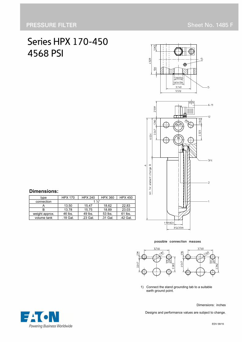
Series HPX 170-450
4568 PSI
PRESSURE FILTER
Sheet No. 1485 F
EDV 09/15
1) Connect the stand grounding tab to a suitable earth ground point.
Dimensions: inches Designs and performance values are subject to change.
Dimensions:
type HPX 170 HPX 240 HPX 360 HPX 450 connection 1 ¼“
A 13.50 15.47 18.62 22.83 B 13.78 15.75 18.89 23.03
weight approx. 46 lbs. 49 lbs. 53 lbs. 61 lbs. volume tank .18 Gal. .23 Gal. .31 Gal. .42 Gal.

Pressure Filter
Series HPX 170-450
4568 PSI
Description: Pressure filter series HPX 170-450 have a working pressure up to 4568 PSI. The HPX filters are manifold mounted.
The filter element consists of star-shaped, pleated filter material, which is supported on the inside by a perforated core tube and is bonded to the end caps with a high-quality adhesive. The flow direction is from outside to inside. Filter elements are available down to 4 µm(c).
Eaton filter elements are known for high intrinsic stability and an excellent filtration capability, a high dirt-retaining capacity and a long service life.
Eaton filter elements can be used for petroleum-based fluids, HW emulsions, water glycols, most synthetic fluids and lubrication fluids. Consult factory for specific fluid applications.
Eaton filter elements are available up to a pressure resistance of p 2320 PSI and a rupture strength ofp 3625 PSI.
The internal valve is integrated into the filter head. After reaching the bypass pressure setting, the bypass valve will send unfiltered partial flow around the filter.
The reversing valve provides another level of protection for the filter element. The reverse flow will not be filtered.
1. Type index:
1.1. Complete filter: (ordering example)
HPX. 360. 10VG. HR. E. P. -. F. 6. -. -. AE1 2 3 4 5 6 7 8 9 10 11 12
1 series: HPX = pressure filter
2 nominal size: 170, 240, 360, 450
3 filter-material and filter-fineness: 80G, 40G, 25G, 10G stainless steel wire mesh 25VG, 16VG, 10VG, 6VG, 3VG microglass
4 filter element collapse rating: 30 = p 435 PSI HR = p 2320 PSI (rupture strength p 3625 PSI)
5 filter element design: E = single-end open
6 sealing material: P = Nitrile (NBR) V = Viton (FPM)
7 filter element specification: (see catalog) - = standard VA = stainless steel IS06 = for HFC applications, see sheet-no. 31601
8 process connection: F = manifold mounted
9 process connection size: 6 = 1 ¼“
10 filter housing specification: (see catalog) - = standard IS06 = for HFC applications, see sheet no.31605
11 internal valve: - = without S1 = with bypass valve p 51 PSI S2 = with bypass valve p 102 PSI R = reversing valve, Q ≤ 55.75 GPM
12 clogging indicator or clogging sensor: - = without AOR = visual, see sheet-no. 1606 AOC = visual, see sheet-no. 1606 AE = visual-electric, see sheet-no. 1615 VS5 = electronic, see sheet-no. 1619
To add an indicator to your filter, use the corresponding indicator data sheet to find the indicator details and add them to the filter assembly model code.
1.2. Filter element: (ordering example)
01E. 360. 10VG. HR. E. P. - 1 2 3 4 5 6 7
1 series: 01E. = filter element according to company standard
2 nominal size: 170, 240, 360, 450
3 - 7 see type index-complete filter

Technical data:
design temperature: 14 °F to +212 °F operating temperature: 14 °F to +176 °F operating medium mineral oil, other media on request max. operating pressure: 4568 PSI test pressure: 6532 PSI process connection: manifold mounted housing material: C-steel sealing material: Nitrile (NBR) or Viton (FPM), other materials on request installation position: vertical
Classified under the Pressure Equipment Directive 2014/68/EC for mineral oil (fluid group 2), Article 4, Para. 3. Classified under ATEX Directive 2014/34/EC according to specific application (see questionnaire sheet-no. 34279-4)
Pressure drop flow curves: Filter calculation/sizing
The pressure drop of the assembly at a given flow rate Q is the sum of the housing ∆p and the element ∆p and is calculated as follows:
p assembly = p housing + p element p housing = (see p = f (Q) - characteristics)
p element (PSI) = .
³
For ease of calculation our Filter Selection tool is available online at www.eatonpowersource.com/calculators/filtration/
Material gradient coefficients (MSK) for filter elements
The material gradient coefficients in PSI/GPM apply to mineral oil (HLP) with a density of 0.876 kg/dm³ and a kinematic viscosity of 139 SUS (30 mm²/s). The pressure drop changes proportionally to the change in kinematic viscosity and density.
HPX VG G
3VG 6VG 10VG 16VG 25VG 25G 40G 80G
170 2.714 1.884 1.206 1.036 0.708 0.0839 0.0783 0.0537
240 2.092 1.452 0.930 0.799 0.546 0.0651 0.0607 0.0416
360 1.530 1.062 0.680 0.584 0.399 0.0475 0.0444 0.0304
450 1.126 0.782 0.500 0.430 0.294 0.0349 0.0326 0.0223
∆p = f(Q) – characteristics according to ISO 3968
The pressure drop characteristics apply to mineral oil (HLP) with a density of 0.876 kg/dm³. The pressure drop changes proportionally to the density.

Symbols:
without indicator with electric indicator
AE 30 and AE 40
with visual-electric indicator
AE 50 and AE 62
with visual-electric indicator
AE 70 and AE 80
with visual indicator
AOR/AOC
with electronic clogging sensor
VS5 filter without internal valve
filter with by-pass valve
filter with reversing valve
Spare parts:
item qty. designation dimension article-no. HPX 170 HPX 240 HPX 360 HPX 450
1 1 filter element 01E.170… 01E.240… 01E.360… 01E.450… 2 1 O-ring 34 x 3,5 304338 (NBR) 304730 (FPM) 3 1 O-ring 75 x 3 302215 (NBR) 304729 (FPM) 4 1 support ring 81 x 2,6 x 1 304581 5 2 O-ring 36 x 3 304358 (NBR) 313900 (FPM) 6 1 clogging indicator, visual AOR or AOC see sheet-no. 1606 7 1 clogging indicator, visual-electric AE see sheet-no. 1615 8 1 clogging sensor, electronic VS5 see sheet-no. 1619 9 1 O-ring 15 x 1,5 315357 (NBR) 315427 (FPM) 10 1 O-ring 22 x 2 304708 (NBR) 304721 (FPM) 11 1 O-ring 14 x 2 304342 (NBR) 304722 (FPM) 12 1 screw plug 20913-4 309817
item 12 execution only without clogging indicator or clogging sensor
Test methods: Filter elements are tested according to the following ISO standards:
ISO 2941 Verification of collapse/burst resistance ISO 2942 Verification of fabrication integrity ISO 2943 Verification of material compatibility with fluids ISO 3723 Method for end load test ISO 3724 Verification of flow fatigue characteristics ISO 3968 Evaluation of pressure drop versus flow characteristics ISO 16889 Multi-pass method for evaluating filtration performance
North America 44 Apple Street Tinton Falls, NJ 07724
Toll Free: 800 656-3344 (North America only)
Tel: +1 732 212-4700 Europe/Africa/Middle East Auf der Heide 2 53947 Nettersheim, Germany
Tel: +49 2486 809-0
Friedensstraße 41 68804 Altlußheim, Germany
Tel: +49 6205 2094-0
An den Nahewiesen 24 55450 Langenlonsheim, Germany
Tel: +49 6704 204-0
China No. 3, Lane 280, Linhong Road Changning District, 200335 Shanghai, P.R. China
Tel: +86 21 5200-0099 Singapore 4 Loyang Lane #04-01/02 Singapore 508914
Tel: +65 6825-1668 Brazil Av. Julia Gaioli, 474 – Bonsucesso 07251-500 – Guarulhos, Brazil
Tel: +55 11 2465-8822
For more information, please email us at [email protected]
or visit www.eaton.com/filtration
© 2015 Eaton. All rights reserved. All trademarks and registered trademarks are the property of their respective owners. All information and recommendations appearing in this brochure concerning the use of products described herein are based on tests believed to be reliable. However, it is the user’s responsibility to determine the suitability for his own use of such products. Since the actual use by others is beyond our control, no guarantee, expressed or implied, is made by Eaton as to the effects of such use or the results to be obtained. Eaton assumes no liability arising out of the use by others of such products. Nor is the information herein to be construed as absolutely complete, since additional information may be necessary or desirable when particular or exceptional conditions or circumstances exist or because of applicable laws or government regulations.

Series HPX 601-1351
4568 PSI
PRESSURE FILTER
Sheet No. 1487 E
EDV 09/15
1) Connect the stand grounding tab to a suitable earth ground point.
Dimensions: inches Designs and performance values are subject to change.
Dimensions:
type HPX 601 HPX 901 HPX 1351 connection 1 ¼“
A 20.86 26.77 36.53 B 12.20 18.11 27.95
weight lbs. 121 136 163 volume tank .55 Gal. .82 Gal. 1.21 Gal.

Pressure Filter
Series HPX 601-1351
4568 PSI
Description: Pressure filter series HPX 601-1351 have a working pressure up to 4568 PSI. The HPX filters are manifold mounted.
The filter element consists of star-shaped, pleated filter material, which is supported on the inside by a perforated core tube and is bonded to the end caps with a high-quality adhesive. The flow direction is from outside to inside. Filter elements are available down to 4 µm(c).
Eaton filter elements are known for high intrinsic stability and an excellent filtration capability, a high dirt-retaining capacity and a long service life.
Eaton filter elements can be used for petroleum-based fluids, HW emulsions, water glycols, most synthetic fluids and lubrication fluids. Consult factory for specific fluid applications.
Eaton filter elements are available up to a pressure resistance of p 2320 PSI and a rupture strength ofp 3625 PSI.
The internal valve is integrated into the filter head. After reaching the bypass pressure setting, the bypass valve will send unfiltered partial flow around the filter.
The reversing valve provides another level of protection for the filter element. The reverse flow will not be filtered.
1. Type index:
1.1. Complete filter: (ordering example)
HPX. 901. 10VG. HR. E. P. -. F. 6. -. -. AE1 2 3 4 5 6 7 8 9 10 11 12
1 series: HPX = pressure filter
2 nominal size: 601, 901, 1351
3 filter-material and filter-fineness: 80G, 40G, 25G, 10G stainless steel wire mesh 25VG, 16VG, 10VG, 6VG, 3VG microglass
4 filter element collapse rating: 30 = p 435 PSI HR = p 2320 PSI (rupture strength p 3625 PSI)
5 filter element design: E = single-end open
6 sealing material: P = Nitrile (NBR) V = Viton (FPM)
7 filter element specification: (see catalog) - = standard VA = stainless steel IS06 = for HFC applications, see sheet-no. 31601
8 process connection: F = manifold mounted
9 process connection size: 6 = 1 ¼“
10 filter housing specification: (see catalog) - = standard IS06 = for HFC applications, see sheet no.31605
11 internal valve: - = without S1 = with bypass valve p 51 PSI S2 = with bypass valve p 102 PSI R = reversing valve, Q ≤ 55.75 GPM
12 clogging indicator or clogging sensor: - = without AOR = visual, see sheet-no. 1606 AOC = visual, see sheet-no. 1606 AE = visual-electric, see sheet-no. 1615 VS5 = electronic, see sheet-no. 1619
To add an indicator to your filter, use the corresponding indicator data sheet to find the indicator details and add them to the filter assembly model code.
1.2. Filter element: (ordering example)
01E. 900. 10VG. HR. E. P. - 1 2 3 4 5 6 7
1 series: 01E. = filter element according to company standard
2 nominal size: 600, 900, 1350
3 - 7 see type index-complete filter
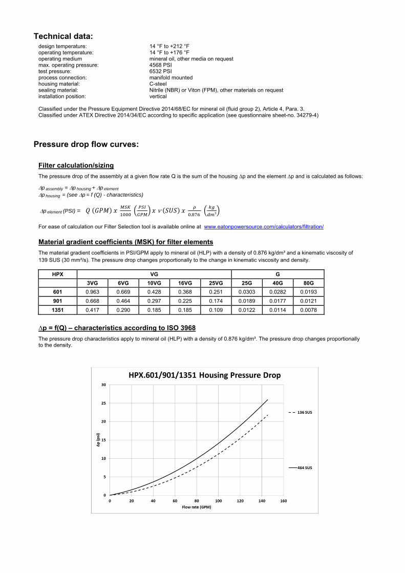
Technical data:
design temperature: 14 °F to +212 °F operating temperature: 14 °F to +176 °F operating medium mineral oil, other media on request max. operating pressure: 4568 PSI test pressure: 6532 PSI process connection: manifold mounted housing material: C-steel sealing material: Nitrile (NBR) or Viton (FPM), other materials on request installation position: vertical
Classified under the Pressure Equipment Directive 2014/68/EC for mineral oil (fluid group 2), Article 4, Para. 3. Classified under ATEX Directive 2014/34/EC according to specific application (see questionnaire sheet-no. 34279-4)
Pressure drop flow curves: Filter calculation/sizing
The pressure drop of the assembly at a given flow rate Q is the sum of the housing ∆p and the element ∆p and is calculated as follows:
p assembly = p housing + p element p housing = (see p = f (Q) - characteristics)
p element (PSI) = .
³
For ease of calculation our Filter Selection tool is available online at www.eatonpowersource.com/calculators/filtration/
Material gradient coefficients (MSK) for filter elements
The material gradient coefficients in PSI/GPM apply to mineral oil (HLP) with a density of 0.876 kg/dm³ and a kinematic viscosity of 139 SUS (30 mm²/s). The pressure drop changes proportionally to the change in kinematic viscosity and density.
HPX VG G
3VG 6VG 10VG 16VG 25VG 25G 40G 80G
601 0.963 0.669 0.428 0.368 0.251 0.0303 0.0282 0.0193
901 0.668 0.464 0.297 0.225 0.174 0.0189 0.0177 0.0121
1351 0.417 0.290 0.185 0.185 0.109 0.0122 0.0114 0.0078
∆p = f(Q) – characteristics according to ISO 3968
The pressure drop characteristics apply to mineral oil (HLP) with a density of 0.876 kg/dm³. The pressure drop changes proportionally to the density.

Symbols: without indicator with electric
indicator AE 30 and AE 40
with visual-electric indicator
AE 50 and AE 62
with visual-electric indicator
AE 70 and AE 80
with visual indicator
AOR/AOC
with electronic clogging sensor
VS5 filter without internal valve
filter with by-pass valve
filter with reversing valve
Spare parts:
item qty. designation dimension article-no. HPX 601 HPX 901 HPX 1351
1 1 filter element 01E.600… 01E.900… 01E.1350… 2 1 O-ring 48 x 3 304357 (NBR) 304404 (FPM) 3 1 O-ring 98 x 4 301914 (NBR) 304765 (FPM) 4 1 support ring 110 x 3,5 x 2 304802 5 2 O-ring 36 x 3 304358 (NBR) 313900 (FPM) 6 1 clogging indicator, visual AOR or AOC see sheet-no. 1606 7 1 clogging indicator, visual-electric AE see sheet-no. 1615 8 1 clogging sensor, electronic VS5 see sheet-no. 1619 9 1 O-ring 15 x 1,5 315357 (NBR) 315427 (FPM)
10 1 O-ring 22 x 2 304708 (NBR) 304721 (FPM) 11 1 O-ring 14 x 2 304342 (NBR) 304722 (FPM) 12 1 screw plug 20913-4 309817 13 1 screw plug BSPP ½ 304678
item 12 execution only without clogging indicator or clogging sensor
Test methods: Filter elements are tested according to the following ISO standards:
ISO 2941 Verification of collapse/burst resistance ISO 2942 Verification of fabrication integrity ISO 2943 Verification of material compatibility with fluids ISO 3723 Method for end load test ISO 3724 Verification of flow fatigue characteristics ISO 3968 Evaluation of pressure drop versus flow characteristics ISO 16889 Multi-pass method for evaluating filtration performance
North America 44 Apple Street Tinton Falls, NJ 07724
Toll Free: 800 656-3344 (North America only)
Tel: +1 732 212-4700 Europe/Africa/Middle East Auf der Heide 2 53947 Nettersheim, Germany
Tel: +49 2486 809-0
Friedensstraße 41 68804 Altlußheim, Germany
Tel: +49 6205 2094-0
An den Nahewiesen 24 55450 Langenlonsheim, Germany
Tel: +49 6704 204-0
China No. 3, Lane 280, Linhong Road Changning District, 200335 Shanghai, P.R. China
Tel: +86 21 5200-0099 Singapore 4 Loyang Lane #04-01/02 Singapore 508914
Tel: +65 6825-1668 Brazil Av. Julia Gaioli, 474 – Bonsucesso 07251-500 – Guarulhos, Brazil
Tel: +55 11 2465-8822
For more information, please email us at [email protected]
or visit www.eaton.com/filtration
© 2015 Eaton. All rights reserved. All trademarks and registered trademarks are the property of their respective owners. All information and recommendations appearing in this brochure concerning the use of products described herein are based on tests believed to be reliable. However, it is the user’s responsibility to determine the suitability for his own use of such products. Since the actual use by others is beyond our control, no guarantee, expressed or implied, is made by Eaton as to the effects of such use or the results to be obtained. Eaton assumes no liability arising out of the use by others of such products. Nor is the information herein to be construed as absolutely complete, since additional information may be necessary or desirable when particular or exceptional conditions or circumstances exist or because of applicable laws or government regulations.

Series HPY 60-150
4568 PSI
PRESSURE FILTER
Sheet No. 1484 F
EDV 09/15
1) Connect the stand grounding tab to a suitable earth ground point.
Dimensions: inches Designs and performance values are subject to change.
Dimensions:
type HPY 60 HPY 90 HPY 150 connection ¾“
A 9.64 12.20 16.49 B 10.63 13.19 17.52
weight approx. 20 lbs. 21 lbs. 23 lbs. volume tank .08 Gal. .10 Gal. .16 Gal.

Pressure Filter
Series HPY 60-150
4568 PSI
Description: Pressure filter series HPY 60-150 have a working pressure up to 4568 PSI. The HPY filters are manifold mounted.
The filter element consists of star-shaped, pleated filter material, which is supported on the inside by a perforated core tube and is bonded to the end caps with a high-quality adhesive. The flow direction is from outside to inside. Filter elements are available down to 4 µm(c).
Eaton filter elements are known for high intrinsic stability and an excellent filtration capability, a high dirt-retaining capacity and a long service life.
Eaton filter elements can be used for petroleum-based fluids, HW emulsions, water glycols, most synthetic fluids and lubrication fluids. Consult factory for specific fluid applications.
Eaton filter elements are available up to a pressure resistance of p 2320 PSI and a rupture strength ofp 3625 PSI.
The internal valve is integrated into the filter head. After reaching the bypass pressure setting, the bypass valve will send unfiltered partial flow around the filter.
The reversing valve provides another level of protection for the filter element. The reverse flow will not be filtered.
1. Type index:
1.1. Complete filter: (ordering example)
HPY. 90. 10VG. HR. E. P. -. F. 4. -. -. AE1 2 3 4 5 6 7 8 9 10 11 12
1 series: HPY = pressure filter
2 nominal size: 60, 90, 150
3 filter-material and filter-fineness: 80G, 40G, 25G, 10G stainless steel wire mesh 25VG, 16VG, 10VG, 6VG, 3VG microglass
4 filter element collapse rating: 30 = p 435 PSI HR = p 2320 PSI (rupture strength p 3625 PSI)
5 filter element design: E = single-end open
6 sealing material: P = Nitrile (NBR) V = Viton (FPM)
7 filter element specification: (see catalog) - = standard VA = stainless steel IS06 = for HFC applications, see sheet-no. 31601
8 process connection: F = manifold mounted
9 process connection size: 4 = ¾“
10 filter housing specification: (see catalog) - = standard IS06 = for HFC applications, see sheet no.31605
11 internal valve: - = without S1 = with bypass valve p 51 PSI S2 = with bypass valve p 102 PSI R = reversing valve, Q ≤ 18.50 GPM
12 clogging indicator or clogging sensor: - = without AOR = visual, see sheet-no. 1606 AOC = visual, see sheet-no. 1606 AE = visual-electric, see sheet-no. 1615 VS5 = electronic, see sheet-no. 1619
To add an indicator to your filter, use the corresponding indicator data sheet to find the indicator details and add them to the filter assembly model code.
1.2. Filter element: (ordering example)
01E. 90. 10VG. HR. E. P. - 1 2 3 4 5 6 7
1 series: 01E. = filter element according to company standard
2 nominal size: 60, 90, 150
3 - 7 see type index-complete filter

Technical data:
design temperature: 14 °F to +212 °F operating temperature: 14 °F to +176 °F operating medium mineral oil, other media on request max. operating pressure: 4568 PSI test pressure: 6532 PSI process connection: manifold mounted housing material: C-steel sealing material: Nitrile (NBR) or Viton (FPM), other materials on request installation position: vertical
Classified under the Pressure Equipment Directive 2014/68/EC for mineral oil (fluid group 2), Article 4, Para. 3. Classified under ATEX Directive 2014/34/EC according to specific application (see questionnaire sheet-no. 34279-4)
Pressure drop flow curves: Filter calculation/sizing
The pressure drop of the assembly at a given flow rate Q is the sum of the housing ∆p and the element ∆p and is calculated as follows:
p assembly = p housing + p element p housing = (see p = f (Q) - characteristics)
p element (PSI) = .
³
For ease of calculation our Filter Selection tool is available online at www.eatonpowersource.com/calculators/filtration/
Material gradient coefficients (MSK) for filter elements
The material gradient coefficients in PSI/GPM apply to mineral oil (HLP) with a density of 0.876 kg/dm³ and a kinematic viscosity of 139 SUS (30 mm²/s). The pressure drop changes proportionally to the change in kinematic viscosity and density.
HPY VG G
3VG 6VG 10VG 16VG 25VG 25G 40G 80G
60 6.748 4.685 2.999 2.577 1.760 0.2002 0.1868 0.1280
90 4.059 2.818 1.804 1.550 1.059 0.1210 0.1130 0.0774
150 2.422 1.681 1.076 0.925 0.632 0.0723 0.0675 0.0462
∆p = f(Q) – characteristics according to ISO 3968
The pressure drop characteristics apply to mineral oil (HLP) with a density of 0.876 kg/dm³. The pressure drop changes proportionally to the density.

Symbols: without indicator with electric
indicator AE 30 and AE 40
with visual-electric indicator
AE 50 and AE 62
with visual-electric indicator
AE 70 and AE 80
with visual indicator
AOR/AOC
with electronic clogging sensor
VS5 filter without internal valve
filter with by-pass valve
filter with reversing valve
Spare parts:
item qty. designation dimension article-no. HPY 60 HPY 90 HPY 150
1 1 filter element 01E.60… 01E.90… 01E.150... 2 1 O-ring 22 x 3,5 304341 (NBR) 304392 (FPM) 3 1 O-ring 54 x 3 304657 (NBR) 304720 (FPM) 4 1 support ring 61 x 2,6 x 1 304660 5 2 O-ring 24 x 3 303038 (NBR) 304397 (FPM) 6 1 clogging indicator, visual AOR or AOC see sheet-no. 1606 7 1 clogging indicator, visual-electric AE see sheet-no. 1615 8 1 clogging sensor, electronic VS5 see sheet-no. 1619 9 1 O-ring 15 x 1,5 315357 (NBR) 315427 (FPM)
10 1 O-ring 22 x 2 304708 (NBR) 304721 (FPM) 11 1 O-ring 14 x 2 304342 (NBR) 304722 (FPM) 12 1 screw plug 20913-4 309817
item 12 execution only without clogging indicator or clogging sensor
Test methods: Filter elements are tested according to the following ISO standards:
ISO 2941 Verification of collapse/burst resistance ISO 2942 Verification of fabrication integrity ISO 2943 Verification of material compatibility with fluids ISO 3723 Method for end load test ISO 3724 Verification of flow fatigue characteristics ISO 3968 Evaluation of pressure drop versus flow characteristics ISO 16889 Multi-pass method for evaluating filtration performance
North America 44 Apple Street Tinton Falls, NJ 07724
Toll Free: 800 656-3344 (North America only)
Tel: +1 732 212-4700 Europe/Africa/Middle East Auf der Heide 2 53947 Nettersheim, Germany
Tel: +49 2486 809-0
Friedensstraße 41 68804 Altlußheim, Germany
Tel: +49 6205 2094-0
An den Nahewiesen 24 55450 Langenlonsheim, Germany
Tel: +49 6704 204-0
China No. 3, Lane 280, Linhong Road Changning District, 200335 Shanghai, P.R. China
Tel: +86 21 5200-0099 Singapore 4 Loyang Lane #04-01/02 Singapore 508914
Tel: +65 6825-1668 Brazil Av. Julia Gaioli, 474 – Bonsucesso 07251-500 – Guarulhos, Brazil
Tel: +55 11 2465-8822
For more information, please email us at [email protected]
or visit www.eaton.com/filtration
© 2015 Eaton. All rights reserved. All trademarks and registered trademarks are the property of their respective owners. All information and recommendations appearing in this brochure concerning the use of products described herein are based on tests believed to be reliable. However, it is the user’s responsibility to determine the suitability for his own use of such products. Since the actual use by others is beyond our control, no guarantee, expressed or implied, is made by Eaton as to the effects of such use or the results to be obtained. Eaton assumes no liability arising out of the use by others of such products. Nor is the information herein to be construed as absolutely complete, since additional information may be necessary or desirable when particular or exceptional conditions or circumstances exist or because of applicable

laws or government regulations.

Series HPY 170-450
4568 PSI
PRESSURE FILTER
Sheet No. 1486 F
EDV 09/15
1) Connect the stand grounding tab to a suitable earth ground point.
Dimensions: inches Designs and performance values are subject to change.
Dimensions:
type HPY 170 HPY 240 HPY 360 HPY 450 connection 1 ¼“
A 13.50 15.47 18.62 22.83 B 13.78 15.75 18.89 23.03
weight approx. 46 lbs. 49 lbs. 53 lbs. 61 lbs. volume tank .18 Gal. .23 Gal. .31 Gal. .42 Gal.

Pressure Filter
Series HPY 170-450
4568 PSI
Description: Pressure filter series HPY 170-450 have a working pressure up to 4568 PSI. The HPY filters are manifold mounted.
The filter element consists of star-shaped, pleated filter material, which is supported on the inside by a perforated core tube and is bonded to the end caps with a high-quality adhesive. The flow direction is from outside to inside. Filter elements are available down to 4 µm(c).
Eaton filter elements are known for high intrinsic stability and an excellent filtration capability, a high dirt-retaining capacity and a long service life.
Eaton filter elements can be used for petroleum-based fluids, HW emulsions, water glycols, most synthetic fluids and lubrication fluids. Consult factory for specific fluid applications.
Eaton filter elements are available up to a pressure resistance of p 2320 PSI and a rupture strength ofp 3625 PSI.
The internal valve is integrated into the filter head. After reaching the bypass pressure setting, the bypass valve will send unfiltered partial flow around the filter.
The reversing valve provides another level of protection for the filter element. The reverse flow will not be filtered.
1. Type index:
1.1. Complete filter: (ordering example)
HPY. 360. 10VG. HR. E. P. -. F. 6. -. -. AE1 2 3 4 5 6 7 8 9 10 11 12
1 series: HPY = pressure filter
2 nominal size: 170, 240, 360, 450
3 filter-material and filter-fineness: 80G, 40G, 25G, 10G stainless steel wire mesh 25VG, 16VG, 10VG, 6VG, 3VG microglass
4 filter element collapse rating: 30 = p 435 PSI HR = p 2320 PSI (rupture strength p 3625 PSI)
5 filter element design: E = single-end open
6 sealing material: P = Nitrile (NBR) V = Viton (FPM)
7 filter element specification: (see catalog) - = standard VA = stainless steel IS06 = for HFC applications, see sheet-no. 31601
8 process connection: F = manifold mounted
9 process connection size: 6 = 1 ¼“
10 filter housing specification: (see catalog) - = standard IS06 = for HFC applications, see sheet no.31605
11 internal valve: - = without S1 = with bypass valve p 51 PSI S2 = with bypass valve p 102 PSI R = reversing valve, Q ≤ 55.75 GPM
12 clogging indicator or clogging sensor: - = without AOR = visual, see sheet-no. 1606 AOC = visual, see sheet-no. 1606 AE = visual-electric, see sheet-no. 1615 VS5 = electronic, see sheet-no. 1619
To add an indicator to your filter, use the corresponding indicator data sheet to find the indicator details and add them to the filter assembly model code.
1.2. Filter element: (ordering example)
01E. 360. 10VG. HR. E. P. - 1 2 3 4 5 6 7
1 series: 01E. = filter element according to company standard
2 nominal size: 170, 240, 360, 450
3 - 7 see type index-complete filter
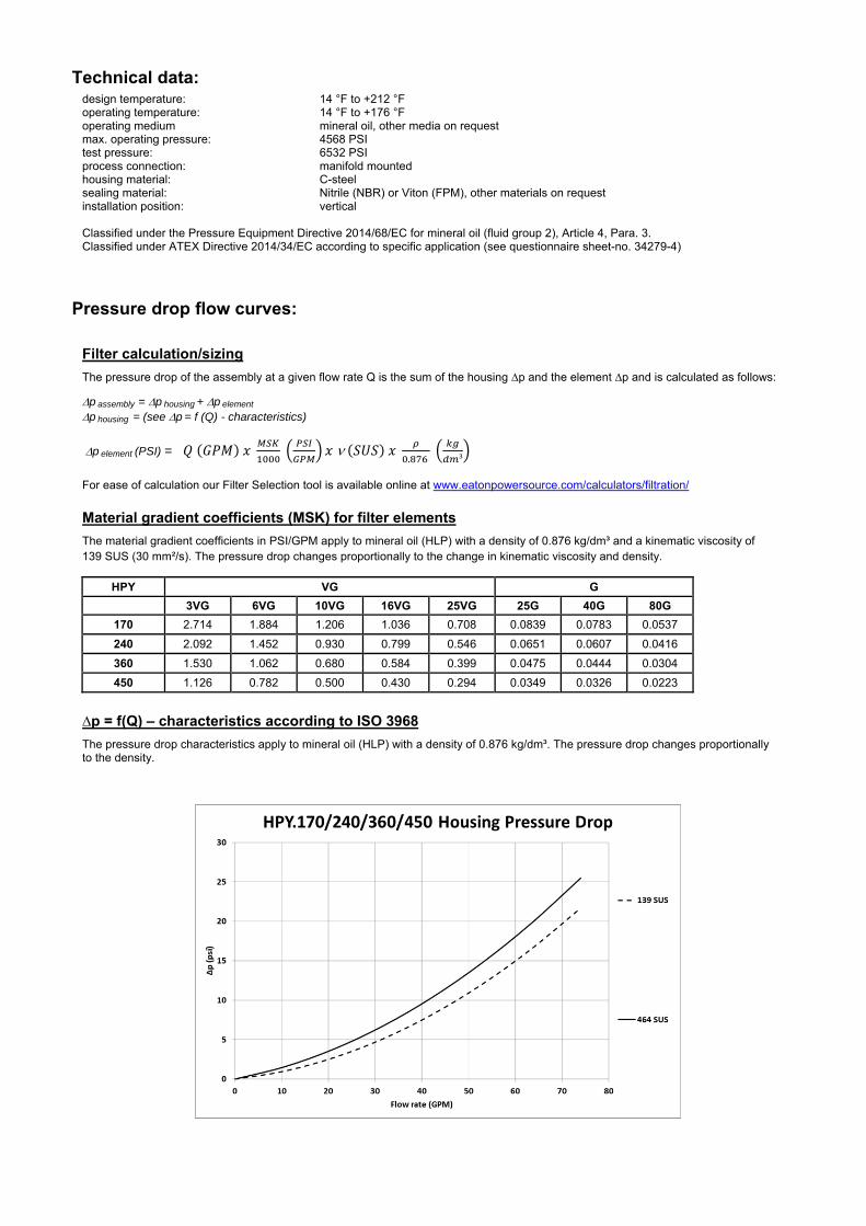
Technical data:
design temperature: 14 °F to +212 °F operating temperature: 14 °F to +176 °F operating medium mineral oil, other media on request max. operating pressure: 4568 PSI test pressure: 6532 PSI process connection: manifold mounted housing material: C-steel sealing material: Nitrile (NBR) or Viton (FPM), other materials on request installation position: vertical
Classified under the Pressure Equipment Directive 2014/68/EC for mineral oil (fluid group 2), Article 4, Para. 3. Classified under ATEX Directive 2014/34/EC according to specific application (see questionnaire sheet-no. 34279-4)
Pressure drop flow curves: Filter calculation/sizing
The pressure drop of the assembly at a given flow rate Q is the sum of the housing ∆p and the element ∆p and is calculated as follows:
p assembly = p housing + p element p housing = (see p = f (Q) - characteristics)
p element (PSI) = .
³
For ease of calculation our Filter Selection tool is available online at www.eatonpowersource.com/calculators/filtration/
Material gradient coefficients (MSK) for filter elements
The material gradient coefficients in PSI/GPM apply to mineral oil (HLP) with a density of 0.876 kg/dm³ and a kinematic viscosity of 139 SUS (30 mm²/s). The pressure drop changes proportionally to the change in kinematic viscosity and density.
HPY VG G
3VG 6VG 10VG 16VG 25VG 25G 40G 80G
170 2.714 1.884 1.206 1.036 0.708 0.0839 0.0783 0.0537
240 2.092 1.452 0.930 0.799 0.546 0.0651 0.0607 0.0416
360 1.530 1.062 0.680 0.584 0.399 0.0475 0.0444 0.0304
450 1.126 0.782 0.500 0.430 0.294 0.0349 0.0326 0.0223
∆p = f(Q) – characteristics according to ISO 3968
The pressure drop characteristics apply to mineral oil (HLP) with a density of 0.876 kg/dm³. The pressure drop changes proportionally to the density.

Symbols: without indicator with electric
indicator AE 30 and AE 40
with visual-electric indicator
AE 50 and AE 62
with visual-electric indicator
AE 70 and AE 80
with visual indicator
AOR/AOC
with electronic clogging sensor
VS5 filter without internal valve
filter with by-pass valve
filter with reversing valve
Spare parts:
item qty. designation dimension article-no. HPY 170 HPY 240 HPY 360 HPY 450
1 1 filter element 01E.170… 01E.240… 01E.360… 01E.450… 2 1 O-ring 34 x 3,5 304338 (NBR) 304730 (FPM) 3 1 O-ring 75 x 3 302215 (NBR) 304729 (FPM) 4 1 support ring 81 x 2,6 x 1 304581 5 2 O-ring 36 x 3 304358 (NBR) 313900 (FPM) 6 1 clogging indicator, visual AOR or AOC see sheet-no. 1606 7 1 clogging indicator, visual-electric AE see sheet-no. 1615 8 1 clogging sensor, electronic VS5 see sheet-no. 1619 9 1 O-ring 15 x 1,5 315357 (NBR) 315427 (FPM) 10 1 O-ring 22 x 2 304708 (NBR) 304721 (FPM) 11 1 O-ring 14 x 2 304342 (NBR) 304722 (FPM) 12 1 screw plug 20913-4 309817
item 12 execution only without clogging indicator or clogging sensor
Test methods: Filter elements are tested according to the following ISO standards:
ISO 2941 Verification of collapse/burst resistance ISO 2942 Verification of fabrication integrity ISO 2943 Verification of material compatibility with fluids ISO 3723 Method for end load test ISO 3724 Verification of flow fatigue characteristics ISO 3968 Evaluation of pressure drop versus flow characteristics ISO 16889 Multi-pass method for evaluating filtration performance
North America 44 Apple Street Tinton Falls, NJ 07724
Toll Free: 800 656-3344 (North America only)
Tel: +1 732 212-4700 Europe/Africa/Middle East Auf der Heide 2 53947 Nettersheim, Germany
Tel: +49 2486 809-0
Friedensstraße 41 68804 Altlußheim, Germany
Tel: +49 6205 2094-0
An den Nahewiesen 24 55450 Langenlonsheim, Germany
Tel: +49 6704 204-0
China No. 3, Lane 280, Linhong Road Changning District, 200335 Shanghai, P.R. China
Tel: +86 21 5200-0099 Singapore 4 Loyang Lane #04-01/02 Singapore 508914
Tel: +65 6825-1668 Brazil Av. Julia Gaioli, 474 – Bonsucesso 07251-500 – Guarulhos, Brazil
Tel: +55 11 2465-8822
For more information, please email us at [email protected]
or visit www.eaton.com/filtration
© 2015 Eaton. All rights reserved. All trademarks and registered trademarks are the property of their respective owners. All information and recommendations appearing in this brochure concerning the use of products described herein are based on tests believed to be reliable. However, it is the user’s responsibility to determine the suitability for his own use of such products. Since the actual use by others is beyond our control, no guarantee, expressed or implied, is made by Eaton as to the effects of such use or the results to be obtained. Eaton assumes no liability arising out of the use by others of such products. Nor is the information herein to be construed as absolutely complete, since additional information may be necessary or desirable when particular or exceptional conditions or circumstances exist or because of applicable laws or government regulations.

Series HPZ 32
5075 PSI
PRESSURE FILTER, for sandwich stacking
Sheet No. 1491 R
EDV 10/15
Weight: approx. 7.7 lbs.
Dimensions: inches Designs and performance values are subject to change.
Left hand installation
Right hand installation

Pressure Filter
Series HPZ 32
5075 PSI
Description: The HPZ series filter is a valve protection filter according to DIN 24340-A6 (D03 & D05 pattern). These pressure filters are mounted between the valve and manifold to provide extra protection for critical valves. The HPZ filter can be mounted on either side of the valve for easy filter maintenance, depending on the filter configuration.
The filter element consists of star-shaped, pleated filter material, which is supported on the inside by a perforated core tube and is bonded to the end caps with a high-quality adhesive. The flow direction is from outside to inside. Filter elements are available down to 4 µm(c).
Eaton filter elements are known for high intrinsic stability and an excellent filtration capability, a high dirt-retaining capacity and a long service life.
Eaton filter elements can be used for petroleum-based fluids, HW emulsions, water glycols, most synthetic fluids and lubrication fluids. Consult factory for specific fluid applications.
Eaton filter elements are available up to a pressure resistance of p 2320 PSI and a rupture strength ofp 3625 PSI.
1. Type index:
1.1. Complete filter: (ordering example)
HPZ. 32. 10VG. HR. E. P. -. Z. 1. -. R. AE1 2 3 4 5 6 7 8 9 10 11 12
1 series: HPZ = pressure filter for sandwich stacking
2 nominal size: 32
3 filter-material and filter-fineness: 80G, 40G, 25G, 10G stainless steel wire mesh 25VG, 16VG, 10VG, 6VG, 3VG microglass
4 filter element collapse rating: 30 = p 435 PSI HR = p 2320 PSI (rupture strength p 3625 PSI)
5 filter element design: E = single-end open
6 sealing material: P = Nitrile (NBR) V = Viton (FPM)
7 filter element specification: - = standard VA = stainless steel
8 process connection: Z = sandwich stacking according to DIN 24340, T2
9 process connection size: 1 = A6 according to DIN 24340, T2
10 filter housing specification: (see catalog) - = standard
11 head design: R = right-hand installation L = left-hand installation
12 clogging indicator or clogging sensor: - = without AOR = visual, see sheet-no. 1606 AOC = visual, see sheet-no. 1606 AE = visual-electric, see sheet-no. 1615 VS5 = electronic, see sheet-no. 1619
To add an indicator to your filter, use the corresponding indicator data sheet to find the indicator details and add them to the filter assembly model code.
1.2. Filter element: (ordering example)
01E. 30. 10VG. HR. E. P. - 1 2 3 4 5 6 7
1 series: 01E. = filter element according to company standard
2 nominal size: 30
3 - 7 see type index-complete filter
.

Technical data:
design temperature: 14 °F to +212 °F operating temperature: 14 °F to +176 °F operating medium mineral oil, other media on request max. operating pressure: 5075 PSI test pressure: 7257 PSI process connection: (master gauge for holes) DIN 24340-A6 housing material: EN-GJS-400-18-LT, C-steel sealing material: Nitrile (NBR) or Viton (FPM), other materials on request installation position: vertical volume tank: 0.02 Gal
Classified under the Pressure Equipment Directive 2014/68/EC for mineral oil (fluid group 2), Article 4, Para. 3. Classified under ATEX Directive 2014/34/EC according to specific application (see questionnaire sheet-no. 34279-4).
Pressure drop flow curves: Filter calculation/sizing
The pressure drop of the assembly at a given flow rate Q is the sum of the housing ∆p and the element ∆p and is calculated as follows:
p assembly = p housing + p element p housing = (see p = f (Q) - characteristics)
p element (PSI) = .
³
For ease of calculation our Filter Selection tool is available online at www.eatonpowersource.com/calculators/filtration/
Material gradient coefficients (MSK) for filter elements
The material gradient coefficients in psi/gpm apply to mineral oil (HLP) with a density of 0.876 kg/dm³ and a kinematic viscosity of 139 SUS (30 mm²/s). The pressure drop changes proportionally to the change in kinematic viscosity and density.
HPZ VG G
3VG 6VG 10VG 16VG 25VG 25G 40G 80G
32 12.554 8.716 5.580 4.794 3.275 0.2539 0.2369 0.1623
∆p = f(Q) – characteristics according to ISO 3968
The pressure drop characteristics apply to mineral oil (HLP) with a density of 0.876 kg/dm³. The pressure drop changes proportionally to the density.

Symbols: without indicator with electric
indicator AE 30 and AE 40
with visual-electric indicator
AE 50 and AE 62
with visual-electric indicator
AE 70 and AE 80
with visual indicator
AOR/AOC
with electronic clogging sensor
VS5
Spare parts: item qty. designation dimension article-no.
1 1 filer element 01E.30… 2 1 support ring SRA 27 x 2,1 x 1 305466 3 1 O-ring 32 x 2,5 306843 (NBR) 308268 (FPM) 4 4 O-ring 9,25 x 1,78 304354 (NBR) 310268 (FPM) 5 1 clogging indicator, visual AOR or AOC see sheet no. 1606 6 1 clogging indicator, visual-electric AE see sheet no. 1615 7 1 clogging sensor, electronic VS5 see sheet no. 1619 8 1 O-ring 15 x 1,5 315357 (NBR) 315427 (FPM) 9 1 O-ring 22 x 2 304708 (NBR) 304721 (FPM)
10 1 O-ring 14 x 2 304342 (NBR) 304722 ( FPM) 11 1 O-ring 11 x 3 312603 (NBR) 312727 (FPM) 12 1 screw plug 20913-4 309817
item 12 execution only without clogging indicator or clogging sensor
Test methods: Filter elements are tested according to the following ISO standards:
ISO 2941 Verification of collapse/burst resistance ISO 2942 Verification of fabrication integrity ISO 2943 Verification of material compatibility with fluids ISO 3723 Method for end load test ISO 3724 Verification of flow fatigue characteristics ISO 3968 Evaluation of pressure drop versus flow characteristics ISO 16889 Multi-pass method for evaluating filtration performance
North America 44 Apple Street Tinton Falls, NJ 07724
Toll Free: 800 656-3344 (North America only)
Tel: +1 732 212-4700 Europe/Africa/Middle East Auf der Heide 2 53947 Nettersheim, Germany
Tel: +49 2486 809-0
Friedensstraße 41 68804 Altlußheim, Germany
Tel: +49 6205 2094-0
An den Nahewiesen 24 55450 Langenlonsheim, Germany
Tel: +49 6704 204-0
China No. 3, Lane 280, Linhong Road Changning District, 200335 Shanghai, P.R. China
Tel: +86 21 5200-0099 Singapore 4 Loyang Lane #04-01/02 Singapore 508914
Tel: +65 6825-1668 Brazil Av. Julia Gaioli, 474 – Bonsucesso 07251-500 – Guarulhos, Brazil
Tel: +55 11 2465-8822
For more information, please email us at [email protected]
or visit www.eaton.com/filtration
© 2015 Eaton. All rights reserved. All trademarks and registered trademarks are the property of their respective owners. All information and recommendations appearing in this brochure concerning the use of products described herein are based on tests believed to be reliable. However, it is the user’s responsibility to determine the suitability for his own use of such products. Since the actual use by others is beyond our control, no guarantee, expressed or implied, is made by Eaton as to the effects of such use or the results to be obtained. Eaton assumes no liability arising out of the use by others of such products. Nor is the information herein to be construed as absolutely complete, since additional information may be necessary or desirable when particular or exceptional conditions or circumstances exist or because of applicable laws or government regulations.

Series HPZ 90
5075 PSI
PRESSURE FILTER, for sandwich stacking
Sheet No. 1493 J
EDV 10/15
Weight: approx. 14.3 lbs.
Dimensions: inches Designs and performance values are subject to change.
Right hand installation
Left hand installation

Pressure Filter
Series HPZ 90
5075 PSI
Description: The HPZ series filter is a valve protection filter according to DIN 24340-A6 (D03 & D05 pattern). These pressure filters are mounted between the valve and manifold to provide extra protection for critical valves. The HPZ filter can be mounted on either side of the valve for easy filter maintenance, depending on the filter configuration.
The filter element consists of star-shaped, pleated filter material, which is supported on the inside by a perforated core tube and is bonded to the end caps with a high-quality adhesive. The flow direction is from outside to inside. Filter elements are available down to 4 µm(c).
Eaton filter elements are known for high intrinsic stability and an excellent filtration capability, a high dirt-retaining capacity and a long service life.
Eaton filter elements can be used for petroleum-based fluids, HW emulsions, water glycols, most synthetic fluids and lubrication fluids. Consult factory for specific fluid applications.
Eaton filter elements are available up to a pressure resistance of p 2320 PSI and a rupture strength ofp 3625 PSI.
1. Type index:
1.1. Complete filter: (ordering example)
HPZ. 90. 10VG. HR. E. P. -. Z. 2. -. R. AE1 2 3 4 5 6 7 8 9 10 11 12
1 series: HPZ = pressure filter for sandwich stacking
2 nominal size: 90
3 filter-material and filter-fineness: 80G, 40G, 25G, 10G stainless steel wire mesh 25VG, 16VG, 10VG, 6VG, 3VG microglass
4 filter element collapse rating: 30 = p 435 PSI HR = p 2320 PSI (rupture strength p 3625 PSI)
5 filter element design: E = single-end open
6 sealing material: P = Nitrile (NBR) V = Viton (FPM)
7 filter element specification: - = standard VA = stainless steel
8 process connection: Z = sandwich stacking according to DIN 24340, T2
9 process connection size: 2 = A10 according to DIN 24340, T2
10 filter housing specification: (see catalog) - = standard
11 head design: R = right-hand installation L = left-hand installation
12 clogging indicator or clogging sensor: - = without AOR = visual, see sheet-no. 1606 AOC = visual, see sheet-no. 1606 AE = visual-electric, see sheet-no. 1615 VS5 = electronic, see sheet-no. 1619
To add an indicator to your filter, use the corresponding indicator data sheet to find the indicator details and add them to the filter assembly model code.
1.2. Filter element: (ordering example)
01E. 90. 10VG. HR. E. P. - 1 2 3 4 5 6 7
1 series: 01E. = filter element according to company standard
2 nominal size: 90
3 - 7 see type index-complete filter
.
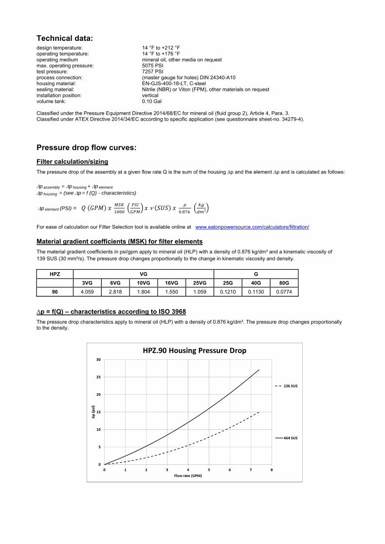
Technical data:
design temperature: 14 °F to +212 °F operating temperature: 14 °F to +176 °F operating medium mineral oil, other media on request max. operating pressure: 5075 PSI test pressure: 7257 PSI process connection: (master gauge for holes) DIN 24340-A10 housing material: EN-GJS-400-18-LT, C-steel sealing material: Nitrile (NBR) or Viton (FPM), other materials on request installation position: vertical volume tank: 0.10 Gal
Classified under the Pressure Equipment Directive 2014/68/EC for mineral oil (fluid group 2), Article 4, Para. 3. Classified under ATEX Directive 2014/34/EC according to specific application (see questionnaire sheet-no. 34279-4).
Pressure drop flow curves: Filter calculation/sizing
The pressure drop of the assembly at a given flow rate Q is the sum of the housing ∆p and the element ∆p and is calculated as follows:
p assembly = p housing + p element p housing = (see p = f (Q) - characteristics)
p element (PSI) = .
³
For ease of calculation our Filter Selection tool is available online at www.eatonpowersource.com/calculators/filtration/
Material gradient coefficients (MSK) for filter elements
The material gradient coefficients in psi/gpm apply to mineral oil (HLP) with a density of 0.876 kg/dm³ and a kinematic viscosity of 139 SUS (30 mm²/s). The pressure drop changes proportionally to the change in kinematic viscosity and density.
HPZ VG G
3VG 6VG 10VG 16VG 25VG 25G 40G 80G
90 4.059 2.818 1.804 1.550 1.059 0.1210 0.1130 0.0774
∆p = f(Q) – characteristics according to ISO 3968
The pressure drop characteristics apply to mineral oil (HLP) with a density of 0.876 kg/dm³. The pressure drop changes proportionally to the density.

Symbols: without indicator with electric
indicator AE 30 and AE 40
with visual-electric indicator
AE 50 and AE 62
with visual-electric indicator
AE 70 and AE 80
with visual indicator
AOR/AOC
with electronic clogging sensor
VS5
Spare parts: item qty. designation dimension article-no.
1 1 filer element 01E.90… 2 1 support ring SRA 52 x 2,6 x 1 311013 3 1 O-ring 45 x 3 304991 (NBR) 304997 (FPM) 4 4 O-ring 12 x 2 311014 (NBR) 310271(FPM) 5 1 clogging indicator, visual AOR or AOC see sheet no. 1606 6 1 clogging indicator, visual-electric AE see sheet no. 1615 7 1 clogging sensor, electronic VS5 see sheet no. 1619 8 1 O-ring 15 x 1,5 315357 (NBR) 315427 (FPM) 9 1 O-ring 22 x 2 304708 (NBR) 304721 (FPM)
10 1 O-ring 14 x 2 304342 (NBR) 304722 ( FPM) 11 1 O-ring 22 x 3,5 304341 (NBR) 304392 (FPM) 12 1 screw plug 20913-4 309817
item 12 execution only without clogging indicator or clogging sensor
Test methods: Filter elements are tested according to the following ISO standards:
ISO 2941 Verification of collapse/burst resistance ISO 2942 Verification of fabrication integrity ISO 2943 Verification of material compatibility with fluids ISO 3723 Method for end load test ISO 3724 Verification of flow fatigue characteristics ISO 3968 Evaluation of pressure drop versus flow characteristics ISO 16889 Multi-pass method for evaluating filtration performance
North America 44 Apple Street Tinton Falls, NJ 07724
Toll Free: 800 656-3344 (North America only)
Tel: +1 732 212-4700 Europe/Africa/Middle East Auf der Heide 2 53947 Nettersheim, Germany
Tel: +49 2486 809-0
Friedensstraße 41 68804 Altlußheim, Germany
Tel: +49 6205 2094-0
An den Nahewiesen 24 55450 Langenlonsheim, Germany
Tel: +49 6704 204-0
China No. 3, Lane 280, Linhong Road Changning District, 200335 Shanghai, P.R. China
Tel: +86 21 5200-0099 Singapore 4 Loyang Lane #04-01/02 Singapore 508914
Tel: +65 6825-1668 Brazil Av. Julia Gaioli, 474 – Bonsucesso 07251-500 – Guarulhos, Brazil
Tel: +55 11 2465-8822
For more information, please email us at [email protected]
or visit www.eaton.com/filtration
© 2015 Eaton. All rights reserved. All trademarks and registered trademarks are the property of their respective owners. All information and recommendations appearing in this brochure concerning the use of products described herein are based on tests believed to be reliable. However, it is the user’s responsibility to determine the suitability for his own use of such products. Since the actual use by others is beyond our control, no guarantee, expressed or implied, is made by Eaton as to the effects of such use or the results to be obtained. Eaton assumes no liability arising out of the use by others of such products. Nor is the information herein to be construed as absolutely complete, since additional information may be necessary or desirable when particular or exceptional conditions or circumstances exist or because of applicable laws or government regulations.

Series HP 31
6000 PSI
PRESSURE FILTER
Sheet No. 1459 F
EDV 09/15
1) Connect the stand grounding tab to a suitable earth ground point.
Weight: approx. 7 lbs. Dimensions: inches Designs and performance values are subject to change.
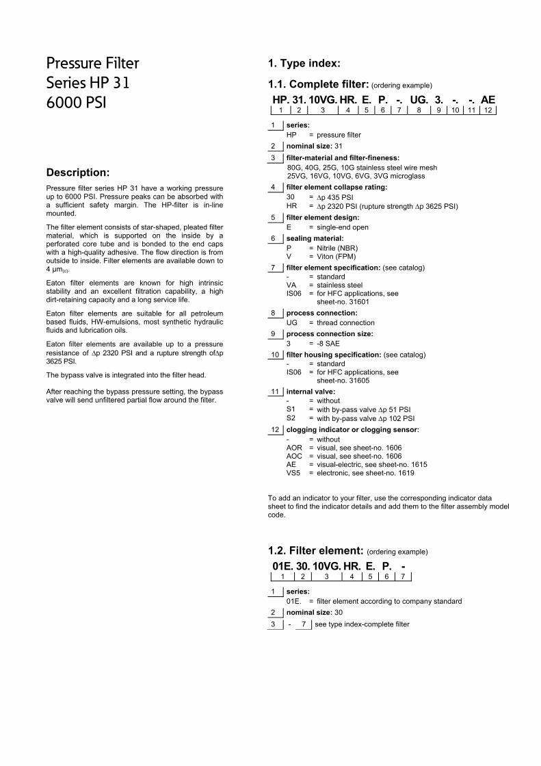
Pressure Filter
Series HP 31
6000 PSI
Description: Pressure filter series HP 31 have a working pressure up to 6000 PSI. Pressure peaks can be absorbed with a sufficient safety margin. The HP-filter is in-line mounted.
The filter element consists of star-shaped, pleated filter material, which is supported on the inside by a perforated core tube and is bonded to the end caps with a high-quality adhesive. The flow direction is from outside to inside. Filter elements are available down to 4 µm(c).
Eaton filter elements are known for high intrinsic stability and an excellent filtration capability, a high dirt-retaining capacity and a long service life.
Eaton filter elements are suitable for all petroleum based fluids, HW-emulsions, most synthetic hydraulic fluids and lubrication oils.
Eaton filter elements are available up to a pressure resistance of p 2320 PSI and a rupture strength ofp 3625 PSI.
The bypass valve is integrated into the filter head. After reaching the bypass pressure setting, the bypass valve will send unfiltered partial flow around the filter.
1. Type index:
1.1. Complete filter: (ordering example)
HP. 31. 10VG. HR. E. P. -. UG. 3. -. -. AE1 2 3 4 5 6 7 8 9 10 11 12
1 series: HP = pressure filter
2 nominal size: 31
3 filter-material and filter-fineness: 80G, 40G, 25G, 10G stainless steel wire mesh 25VG, 16VG, 10VG, 6VG, 3VG microglass
4 filter element collapse rating: 30 = p 435 PSI HR = p 2320 PSI (rupture strength p 3625 PSI)
5 filter element design: E = single-end open
6 sealing material: P = Nitrile (NBR) V = Viton (FPM)
7 filter element specification: (see catalog) - = standard VA = stainless steel IS06 = for HFC applications, see
sheet-no. 31601
8 process connection: UG = thread connection
9 process connection size: 3 = -8 SAE
10 filter housing specification: (see catalog) - = standard IS06 = for HFC applications, see
sheet-no. 31605
11 internal valve: - = without S1 = with by-pass valve p 51 PSI S2 = with by-pass valve p 102 PSI
12 clogging indicator or clogging sensor: - = without AOR = visual, see sheet-no. 1606 AOC = visual, see sheet-no. 1606 AE = visual-electric, see sheet-no. 1615 VS5 = electronic, see sheet-no. 1619
To add an indicator to your filter, use the corresponding indicator data sheet to find the indicator details and add them to the filter assembly model code.
1.2. Filter element: (ordering example)
01E. 30. 10VG. HR. E. P. - 1 2 3 4 5 6 7
1 series: 01E. = filter element according to company standard
2 nominal size: 30
3 - 7 see type index-complete filter

Technical data:
design temperature: 14 °F to +212 °F operating temperature: 14 °F to +176 °F operating medium mineral oil, other media on request max. operating pressure: 6000 PSI test pressure: 8580 PSI process connection: thread connection housing material: C-steel sealing material: Nitrile (NBR) or Viton (FPM), other materials on request installation position: vertical volume tank: 0.02 Gal
Classified under the Pressure Equipment Directive 2014/68/EC for mineral oil (fluid group 2), Article 4, Para. 3. Classified under ATEX Directive 2014/34/EC according to specific application (see questionnaire sheet-no. 34279-4).
Pressure drop flow curves: Filter calculation/sizing
The pressure drop of the assembly at a given flow rate Q is the sum of the housing ∆p and the element ∆p and is calculated as follows:
p assembly = p housing + p element p housing = (see p = f (Q) - characteristics)
p element (PSI) = .
³
For ease of calculation our Filter Selection tool is available online at www.eatonpowersource.com/calculators/filtration/
Material gradient coefficients (MSK) for filter elements
The material gradient coefficients in psi/gpm apply to mineral oil (HLP) with a density of 0.876 kg/dm³ and a kinematic viscosity of 139 SUS (30 mm²/s). The pressure drop changes proportionally to the change in kinematic viscosity and density.
HP VG G
3VG 6VG 10VG 16VG 25VG 25G 40G 80G
31 12.554 8.716 5.580 4.794 3.275 0.2369 0.2369 0.1623
∆p = f(Q) – characteristics according to ISO 3968
The pressure drop characteristics apply to mineral oil (HLP) with a density of 0.876 kg/dm³. The pressure drop changes proportionally to the density.

Symbols: without indicator with electric
indicator AE 30 and AE 40
with visual-electric indicator
AE 50 and AE 62
with visual-electric indicator
AE 70 and AE 80
with visual indicator
AOR/AOC
with electronic clogging sensor
VS5
filter without internal valve
filter with by-pass valve
Spare parts:
item qty. designation dimension article-no. 1 1 filter element 01E. 30 2 1 O-ring 11 x 3 312603 (NBR) 312727 (FPM) 3 1 O-ring 40 x 3 304389 (NBR) 304391 (FPM) 4 1 support ring 48 x 2,6 x 1 305391 5 1 clogging indicator, visual AOR or AOC see sheet-no. 1606 6 1 clogging indicator, visual-electric AE see sheet-no. 1615 7 1 clogging sensor, electronic VS5 see sheet-no. 1619 8 1 O-ring 15 x 1,5 315357 (NBR) 315427 (FPM) 9 1 O-ring 22 x 2 304708 (NBR) 304721 (FPM)
10 1 O-ring 14 x 2 304342 (NBR) 304722 (FPM) 11 1 screw plug 20913-4 309817
item 11 execution only without clogging indicator or clogging sensor
Test methods: Filter elements are tested according to the following ISO standards:
ISO 2941 Verification of collapse/burst resistance ISO 2942 Verification of fabrication integrity ISO 2943 Verification of material compatibility with fluids ISO 3723 Method for end load test ISO 3724 Verification of flow fatigue characteristics ISO 3968 Evaluation of pressure drop versus flow characteristics ISO 16889 Multi-pass method for evaluating filtration performance
North America 44 Apple Street Tinton Falls, NJ 07724
Toll Free: 800 656-3344 (North America only)
Tel: +1 732 212-4700 Europe/Africa/Middle East Auf der Heide 2 53947 Nettersheim, Germany
Tel: +49 2486 809-0
Friedensstraße 41 68804 Altlußheim, Germany
Tel: +49 6205 2094-0
An den Nahewiesen 24 55450 Langenlonsheim, Germany
Tel: +49 6704 204-0
China No. 3, Lane 280, Linhong Road Changning District, 200335 Shanghai, P.R. China
Tel: +86 21 5200-0099 Singapore 4 Loyang Lane #04-01/02 Singapore 508914
Tel: +65 6825-1668 Brazil Av. Julia Gaioli, 474 – Bonsucesso 07251-500 – Guarulhos, Brazil
Tel: +55 11 2465-8822
For more information, please email us at [email protected]
or visit www.eaton.com/filtration
© 2015 Eaton. All rights reserved. All trademarks and registered trademarks are the property of their respective owners. All information and recommendations appearing in this brochure concerning the use of products described herein are based on tests believed to be reliable. However, it is the user’s responsibility to determine the suitability for his own use of such products. Since the actual use by others is beyond our control, no guarantee, expressed or implied, is made by Eaton as to the effects of such use or the results to be obtained. Eaton assumes no liability arising out of the use by others of such products. Nor is the information herein to be construed as absolutely complete, since additional information may be necessary or desirable when particular or exceptional conditions or circumstances exist or because of applicable laws or government regulations.

Series HP 61-151
6000 PSI
PRESSURE FILTER
Sheet No. 1477 H
EDV 09/15
1) Connect the stand grounding tab to a suitable earth ground point.
Dimensions: inches Designs and performance values are subject to change.
Dimensions:
Type HP 61 HP 91 HP 151 Connection - 8 SAE -12 SAE -16 SAE
A 8.11 10.66 14.96 B 7.08 9.64 13.93 C 10.63 13.19 17.52
Weight approx. 8.80 lbs. 9.90 lbs. 12.10 lbs. Volume tank 0.08 gal. 0.10 gal. 0.16 gal.

Pressure Filter
Series HP 61-151
6000 PSI
Description: Pressure filter series HP 61-151 have a working pressure up to 6000 PSI. Pressure peaks can be absorbed with a sufficient safety margin. The HP-filter is in-line mounted.
The filter element consists of star-shaped, pleated filter material, which is supported on the inside by a perforated core tube and is bonded to the end caps with a high-quality adhesive. The flow direction is from outside to inside. Filter elements are available down to 4 µm(c).
Eaton filter elements are known for high intrinsic stability and an excellent filtration capability, a high dirt-retaining capacity and a long service life.
Eaton filter elements are suitable for all petroleum based fluids, HW-emulsions, most synthetic hydraulic fluids and lubrication oils.
Eaton filter elements are available up to a pressure resistance of p 2320 PSI and a rupture strength ofp 3625 PSI.
The internal valve is integrated into the filter head. After reaching the bypass pressure setting, the bypass valve will send unfiltered partial flow around the filter.
The reversing valve provides another level of protection for the filter element. The reverse flow will not be filtered.
1. Type index:
1.1. Complete filter: (ordering example)
HP. 91. 10VG. HR. E. P. -. UG. 4. -. -. AE1 2 3 4 5 6 7 8 9 10 11 12
1 series: HP = pressure filter
2 nominal size: 61, 91, 151
3 filter-material and filter-fineness: 80G, 40G, 25G, 10G stainless steel wire mesh 25VG, 16VG, 10VG, 6VG, 3VG microglass
4 filter element collapse rating: 30 = p 435 PSI HR = p 2320 PSI (rupture strength p 3625 PSI)
5 filter element design: E = single-end open
6 sealing material: P = Nitrile (NBR) V = Viton (FPM)
7 filter element specification: (see catalog) - = standard VA = stainless steel IS06 = for HFC applications, see
sheet-no. 31601
8 process connection: UG = thread connection
9 process connection size: 3 = -8 SAE 4 = -12 SAE 5 = -16 SAE
10 filter housing specification: (see catalog) - = standard IS06 = for HFC applications, see
sheet no.31605
11 internal valve: - = without S1 = with bypass valve p 51 PSI S2 = with bypass valve p 102 PSI R = reversing valve, Q ≤ 18.50 GPM
12 clogging indicator or clogging sensor: - = without AOR = visual, see sheet-no. 1606 AOC = visual, see sheet-no. 1606 AE = visual-electric, see sheet-no. 1615 VS5 = electronic, see sheet-no. 1619
To add an indicator to your filter, use the corresponding indicator data sheet to find the indicator details and add them to the filter assembly model code.
1.2. Filter element: (ordering example)
01E. 90. 10VG. HR. E. P. - 1 2 3 4 5 6 7
1 series: 01E. = filter element according to company standard
2 nominal size: 60, 90, 150
3 - 7 see type index-complete filter

Technical data:
design temperature: 14 °F to +212 °F operating temperature: 14 °F to +176 °F operating medium mineral oil, other media on request max. operating pressure: 6000 PSI test pressure: 8580 PSI process connection: thread connection housing material: C-steel sealing material: Nitrile (NBR) or Viton (FPM), other materials on request installation position: vertical
Classified under the Pressure Equipment Directive 2014/68/EC for mineral oil (fluid group 2), Article 4, Para. 3. Classified under ATEX Directive 2014/34/EC according to specific application (see questionnaire sheet-no. 34279-4)
Pressure drop flow curves:
Filter calculation/sizing
The pressure drop of the assembly at a given flow rate Q is the sum of the housing ∆p and the element ∆p and is calculated as follows:
p assembly = p housing + p element p housing = (see p = f (Q) - characteristics)
p element (PSI) = .
³
For ease of calculation our Filter Selection tool is available online at www.eatonpowersource.com/calculators/filtration/
Material gradient coefficients (MSK) for filter elements
The material gradient coefficients in PSI/GPM apply to mineral oil (HLP) with a density of 0.876 kg/dm³ and a kinematic viscosity of 139 SUS (30 mm²/s). The pressure drop changes proportionally to the change in kinematic viscosity and density.
HP VG G
3VG 6VG 10VG 16VG 25VG 25G 40G 80G
61 6.748 4.685 2.999 2.577 1.760 0.2002 0.1868 0.1280
91 4.059 2.818 1.804 1.550 1.059 0.1210 0.1130 0.0774
151 2.422 1.681 1.076 0.925 0.632 0.0723 0.0675 0.0462
∆p = f(Q) – characteristics according to ISO 3968
The pressure drop characteristics apply to mineral oil (HLP) with a density of 0.876 kg/dm³. The pressure drop changes proportionally to the density.

Symbols: without indicator with electric
indicator AE 30 and AE 40
with visual-electric indicator
AE 50 and AE 62
with visual-electric indicator
AE 70 and AE 80
with visual indicator
AOR/AOC
with electronic clogging sensor
VS5
filter without internal valve
filter with by-pass valve
filter with reversing valve
Spare parts: item qty. designation dimension article-no.
HP61 HP91 HP151 1 1 filter element 01E.60… 01E.90… 01E.150… 2 1 O-ring 11 x 3 312603 (NBR) 312727 (FPM) 3 1 O-ring 40 x 3 304389 (NBR) 304391 (FPM) 4 1 support ring 48 x 2,6 x 1 305391 5 1 clogging indicator, visual AOR or AOC see sheet-no. 1606 6 1 clogging indicator, visual-electric AE see sheet-no. 1615 7 1 clogging sensor, electronic VS5 see sheet-no. 1619 8 1 O-ring 15 x 1,5 315357 (NBR) 315427 (FPM) 9 1 O-ring 22 x 2 304708 (NBR) 304721 (FPM)
10 1 O-ring 14 x 2 304342 (NBR) 304722 (FPM) 11 1 screw plug 20913-4 309817
item 11 execution only without clogging indicator or clogging sensor
Test methods: Filter elements are tested according to the following ISO standards:
ISO 2941 Verification of collapse/burst resistance ISO 2942 Verification of fabrication integrity ISO 2943 Verification of material compatibility with fluids ISO 3723 Method for end load test ISO 3724 Verification of flow fatigue characteristics ISO 3968 Evaluation of pressure drop versus flow characteristics ISO 16889 Multi-pass method for evaluating filtration performance
North America 44 Apple Street Tinton Falls, NJ 07724
Toll Free: 800 656-3344 (North America only)
Tel: +1 732 212-4700 Europe/Africa/Middle East Auf der Heide 2 53947 Nettersheim, Germany
Tel: +49 2486 809-0
Friedensstraße 41 68804 Altlußheim, Germany
Tel: +49 6205 2094-0
An den Nahewiesen 24 55450 Langenlonsheim, Germany
Tel: +49 6704 204-0
China No. 3, Lane 280, Linhong Road Changning District, 200335 Shanghai, P.R. China
Tel: +86 21 5200-0099 Singapore 4 Loyang Lane #04-01/02 Singapore 508914
Tel: +65 6825-1668 Brazil Av. Julia Gaioli, 474 – Bonsucesso 07251-500 – Guarulhos, Brazil
Tel: +55 11 2465-8822
For more information, please email us at [email protected]
or visit www.eaton.com/filtration
© 2015 Eaton. All rights reserved. All trademarks and registered trademarks are the property of their respective owners. All information and recommendations appearing in this brochure concerning the use of products described herein are based on tests believed to be reliable. However, it is the user’s responsibility to determine the suitability for his own use of such products. Since the actual use by others is beyond our control, no guarantee, expressed or implied, is made by Eaton as to the effects of such use or the results to be obtained. Eaton assumes no liability arising out of the use by others of such products. Nor is the information herein to be construed as absolutely complete, since additional information may be necessary or desirable when particular or exceptional conditions or circumstances exist or because of applicable laws or government regulations.

Series HP 170-450
6000 PSI
PRESSURE FILTER
Sheet No. 1462 R
EDV 09/15
1) Connect the stand grounding tab to a suitable earth ground point.
Dimensions: inches Designs and performance values are subject to change.
Dimensions:
type HP 170 HP 240 HP 360 HP 450 connection 1 ½“ SAE
A 12.56 14.49 17.68 21.81 B 10.47 12.44 15.59 19.72 C 13.78 15.75 18.90 23.03 D 3.13 E 1.45 F M16, .79 deep
weight 28.6 lbs. 30.8 lbs. 35.2 lbs. 41.8 lbs. volume tank 0.18 Gal. 0.23 Gal. 0.31 Gal. 0.42 Gal.

Pressure Filter
Series HP 170-450
6000 PSI
Description: Pressure filter series HP 170-450 have a working pressure up to 6000 PSI. Pressure peaks can be absorbed with a sufficient safety margin. The HP-filter is in-line mounted.
The filter element consists of star-shaped, pleated filter material, which is supported on the inside by a perforated core tube and is bonded to the end caps with a high-quality adhesive. The flow direction is from outside to inside. Filter elements are available down to 4 µm(c).
Eaton filter elements are known for high intrinsic stability and an excellent filtration capability, a high dirt-retaining capacity and a long service life.
Eaton filter elements are suitable for all petroleum based fluids, HW-emulsions, most synthetic hydraulic fluids and lubrication oils.
Eaton filter elements are available up to a pressure resistance of p 2320 PSI and a rupture strength ofp 3625 PSI.
The internal valve is integrated into the filter head. After reaching the bypass pressure setting, the bypass valve will send unfiltered partial flow around the filter.
The reversing valve provides another level of protection for the filter element. The reverse flow will not be filtered.
1. Type index:
1.1. Complete filter: (ordering example)
HP. 170. 10VG. HR. E. P. -. FS. 7. -. -. AE1 2 3 4 5 6 7 8 9 10 11 12
1 series: HP = pressure filter
2 nominal size: 170, 240, 360, 450
3 filter-material and filter-fineness: 80G, 40G, 25G, 10G stainless steel wire mesh 25VG, 16VG, 10VG, 6VG, 3VG glass fiber
4 filter element collapse rating: 30 = p 435 PSI HR = p 2320 PSI (rupture strength p 3625 PSI)
5 filter element design: E = single-end open
6 sealing material: P = Nitrile (NBR) V = Viton (FPM)
7 filter element specification: (see catalog) - = standard VA = stainless steel IS06 = for HFC applications, see
sheet-no. 31601
8 process connection: FS = SAE-flange 6000 PSI
9 process connection size: 7 = 1 ½“
10 filter housing specification: (see catalog) - = standard IS06 = for HFC applications, see
sheet-no. 31605
11 internal valve: - = without S1 = with bypass valve p 51 PSI S2 = with bypass valve p 102 PSI R = reversing valve, Q ≤ 55.75 GPM
12 clogging indicator or clogging sensor: - = without AOR = visual, see sheet-no. 1606 AOC = visual, see sheet-no. 1606 AE = visual-electric, see sheet-no. 1615 VS5 = electronic, see sheet-no. 1619
To add an indicator to your filter, use the corresponding indicator data sheet to find the indicator details and add them to the filter assembly model code.
1.2. Filter element: (ordering example)
01E. 170. 10VG. HR. E. P. - 1 2 3 4 5 6 7
1 series: 01E. = filter element according to company standard
2 nominal size: 170, 240, 360, 450
3 - 7 see type index-complete filter

Technical data:
design temperature: 14 °F to +212 °F operating temperature: 14 °F to +176 °F operating medium mineral oil, other media on request max. operating pressure: 6000 PSI test pressure: 8580 PSI process connection: SAE-flange 6000 PSI housing material: EN-GJS-400-18-LT; C-steel (filter bowl) sealing material: Nitrile (NBR) or Viton (FPM), other materials on request installation position: vertical
Classified under the Pressure Equipment Directive 2014/68/EC for mineral oil (fluid group 2), Article 4, Para. 3. Classified under ATEX Directive 2014/34/EC according to specific application (see questionnaire sheet-no. 34279-4).
Pressure drop flow curves:
Filter calculation/sizing
The pressure drop of the assembly at a given flow rate Q is the sum of the housing ∆p and the element ∆p and is calculated as follows:
p assembly = p housing + p element p housing = (see p = f (Q) - characteristics)
p element (PSI) = .
³
For ease of calculation our Filter Selection tool is available online at www.eatonpowersource.com/calculators/filtration/
Material gradient coefficients (MSK) for filter elements
The material gradient coefficients in PSI/GPM apply to mineral oil (HLP) with a density of 0.876 kg/dm³ and a kinematic viscosity of 139 SUS (30 mm²/s). The pressure drop changes proportionally to the change in kinematic viscosity and density.
HP VG G
3VG 6VG 10VG 16VG 25VG 25G 40G 80G
170 2.714 1.884 1.206 1.036 0.708 0.0839 0.0783 0.0537
240 2.092 1.452 0.930 0.799 0.546 0.0651 0.0607 0.0416
360 1.530 1.062 0.680 0.584 0.399 0.0475 0.0444 0.0304
450 1.126 0.782 0.500 0.430 0.294 0.0349 0.0326 0.0223
∆p = f(Q) – characteristics according to ISO 3968
The pressure drop characteristics apply to mineral oil (HLP) with a density of 0.876 kg/dm³. The pressure drop changes proportionally to the density.

Symbols: without indicator with electric
indicator AE 30 and AE 40
with visual-electric indicator
AE 50 and AE 62
with visual-electric indicator
AE 70 and AE 80
with visual indicator
AOR/AOC
with electronic clogging sensor
VS5
filter without internal valve
filter with by-pass valve
filter with reversing valve
Spare parts:
item qty. designation dimension article-no. HP 170 HP 240 HP 360 HP 450
1 1 filter element 01E. 170… 01E.240… 01E.360… 01E.450… 2 1 O-ring 34 x 3,5 304338 (NBR) 304730 (FPM) 3 1 O-ring 75 x 3 302215 (NBR) 304729 (FPM) 4 1 support ring 81 x 2,6 x 1 304581 5 1 clogging indicator visual AOR or AOC see sheet-no. 1606 6 1 clogging indicator visual-electric AE see sheet-no. 1615 7 1 clogging sensor electronic VS5 see sheet-no. 1619 8 1 O-ring 15 x 1,5 315357 (NBR) 315427 (FPM) 9 1 O-ring 22 x 2 304708 (NBR) 304721 (FPM)
10 1 O-ring 14 x 2 304342 (NBR) 304722 (FPM) 11 1 screw plug 20913-4 309817
item 11 execution only without clogging indicator or clogging sensor
Test methods: Filter elements are tested according to the following ISO standards:
ISO 2941 Verification of collapse/burst resistance ISO 2942 Verification of fabrication integrity ISO 2943 Verification of material compatibility with fluids ISO 3723 Method for end load test ISO 3724 Verification of flow fatigue characteristics ISO 3968 Evaluation of pressure drop versus flow characteristics ISO 16889 Multi-pass method for evaluating filtration performance
North America 44 Apple Street Tinton Falls, NJ 07724
Toll Free: 800 656-3344 (North America only)
Tel: +1 732 212-4700 Europe/Africa/Middle East Auf der Heide 2 53947 Nettersheim, Germany
Tel: +49 2486 809-0
Friedensstraße 41 68804 Altlußheim, Germany
Tel: +49 6205 2094-0
An den Nahewiesen 24 55450 Langenlonsheim, Germany
Tel: +49 6704 204-0
China No. 3, Lane 280, Linhong Road Changning District, 200335 Shanghai, P.R. China
Tel: +86 21 5200-0099 Singapore 4 Loyang Lane #04-01/02 Singapore 508914
Tel: +65 6825-1668 Brazil Av. Julia Gaioli, 474 – Bonsucesso 07251-500 – Guarulhos, Brazil
Tel: +55 11 2465-8822
For more information, please email us at [email protected]
or visit www.eaton.com/filtration
© 2015 Eaton. All rights reserved. All trademarks and registered trademarks are the property of their respective owners. All information and recommendations appearing in this brochure concerning the use of products described herein are based on tests believed to be reliable. However, it is the user’s responsibility to determine the suitability for his own use of such products. Since the actual use by others is beyond our control, no guarantee, expressed or implied, is made by Eaton as to the effects of such use or the results to be obtained. Eaton assumes no liability arising out of the use by others of such products. Nor is the information herein to be construed as absolutely complete, since additional information may be necessary or desirable when particular or exceptional conditions or circumstances exist or because of applicable laws or government regulations.

Series HP 171-451
6000 PSI
PRESSURE FILTER
Sheet No. 1468 G
EDV 09/15
Dimensions: inches Designs and performance values are subject to change.
Dimensions:
type HP 171 connection -16SAE -20SAE -24SAE
A 11.33 11.61 11.81 B 10.23 10.35 10.43 C 13.77 13.77 13.77 D 1.10 1.25 1.37 E 2.75 2.87 2.95 F 4.40 4.56 4.56
weight 24 lbs. 25 lbs. 26 lbs. volume tank 0.18 Gal.
type HP 241
connection -16SAE -20SAE -24SAE A 11.33 11.61 11.81 B 10.23 10.35 10.43 C 13.77 13.77 13.77 D 1.10 1.25 1.37 E 2.75 2.87 2.95 F 4.40 4.56 4.56
weight 24 lbs. 25 lbs. 26 lbs. volume tank 23 Gal.
type HP 361
connection -16SAE -20SAE -24SAE A 16.45 16.73 16.92 B 15.35 15.47 15.55 C 18.89 18.89 18.89 D 1.10 1.25 1.37 E 2.75 2.87 2.95 F 4.40 4.56 4.56
weight 31 lbs. 32 lbs. 33 lbs. volume tank 0.31 Gal.
type HP 451
connection -16SAE -20SAE -24SAE A 20.59 20.86 21.06 B 19.48 19.60 19.68 C 23.03 23.03 23.03 D 1.10 1.25 1.37 E 2.75 2.87 2.95 F 4.40 4.56 4.56
weight 36 lbs. 38 lbs. 39 lbs. volume tank 0.42 Gal.
1) Connect the stand grounding tab to a suitable earth ground point.

Pressure Filter
Series HP 171-451
6000 PSI
Description: Pressure filter series HP 171-451 have a working pressure up to 6000 PSI. Pressure peaks can be absorbed with a sufficient safety margin. The HP-filter is in-line mounted.
The filter element consists of star-shaped, pleated filter material, which is supported on the inside by a perforated core tube and is bonded to the end caps with a high-quality adhesive. The flow direction is from outside to inside. Filter elements are available down to 4 µm(c).
Eaton filter elements are known for high intrinsic stability and an excellent filtration capability, a high dirt-retaining capacity and a long service life.
Eaton filter elements are suitable for all petroleum based fluids, HW-emulsions, most synthetic hydraulic fluids and lubrication oils.
Eaton filter elements are available up to a pressure resistance of p 2320 PSI and a rupture strength ofp 3625 PSI.
The bypass valve is integrated into the filter head. After reaching the bypass pressure setting, the bypass valve will send unfiltered partial flow around the filter.
The reversing valve provides another level of protection for the filter element. The reverse flow will not be filtered.
1. Type index:
1.1. Complete filter: (ordering example)
HP. 171. 10VG. HR. E. P. -. UG. 5. -. -. AE1 2 3 4 5 6 7 8 9 10 11 12
1 series: HP = pressure filter
2 nominal size: 171, 241, 361, 451
3 filter-material and filter-fineness: 80G, 40G, 25G, 10G stainless steel wire mesh 25VG, 16VG, 10VG, 6VG, 3VG microglass
4 filter element collapse rating: 30 = p 435 PSI HR = p 2320 PSI (rupture strength p 3625 PSI)
5 filter element design: E = single-end open
6 sealing material: P = Nitrile (NBR) V = Viton (FPM)
7 filter element specification: (see catalog) - = standard VA = stainless steel IS06 = for HFC applications, see
sheet-no. 31601
8 process connection: UG = thread connection
9 process connection size: 5 = -16 SAE 6 = -20 SAE 7 = -24 SAE
10 filter housing specification: (see catalog) - = standard IS06 = for HFC applications, see
sheet-no. 31605
11 internal valve: - = without S1 = with by-pass valve p 51 PSI S2 = with by-pass valve p 102 PSI R = reversing valve, Q ≤ 55.75 GPM
12 clogging indicator or clogging sensor: - = without AOR = visual, see sheet-no. 1606 AOC = visual, see sheet-no. 1606 AE = visual-electric, see sheet-no. 1615 VS5 = electronic, see sheet-no. 1619
To add an indicator to your filter, use the corresponding indicator data sheet to find the indicator details and add them to the filter assembly model code.
1.2. Filter element: (ordering example)
01E. 170. 10VG. HR. E. P. - 1 2 3 4 5 6 7
1 series: 01E. = filter element according to company standard
2 nominal size: 170, 240, 360, 450
3 - 7 see type index-complete filter

Technical data:
design temperature: 14 °F to +212 °F operating temperature: 14 °F to +176 °F operating medium mineral oil, other media on request max. operating pressure: 6000 PSI test pressure: 8580 PSI process connection: thread connection housing material: C-steel sealing material: Nitrile (NBR) or Viton (FPM), other materials on request installation position: vertical
Classified under the Pressure Equipment Directive 2014/68/EC for mineral oil (fluid group 2), Article 4, Para. 3. Classified under ATEX Directive 2014/34/EC according to specific application (see questionnaire sheet-no. 34279-4).
Pressure drop flow curves:
Filter calculation/sizing
The pressure drop of the assembly at a given flow rate Q is the sum of the housing ∆p and the element ∆p and is calculated as follows:
p assembly = p housing + p element p housing = (see p = f (Q) - characteristics)
p element (PSI) = .
³
For ease of calculation our Filter Selection tool is available online at www.eatonpowersource.com/calculators/filtration/
Material gradient coefficients (MSK) for filter elements
The material gradient coefficients in PSI/GPM apply to mineral oil (HLP) with a density of 0.876 kg/dm³ and a kinematic viscosity of 139 SUS (30 mm²/s). The pressure drop changes proportionally to the change in kinematic viscosity and density.
HP VG G
3VG 6VG 10VG 16VG 25VG 25G 40G 80G
171 2.714 1.884 1.206 1.036 0.708 0.0839 0.0783 0.0537
241 2.092 1.452 0.930 0.799 0.546 0.0651 0.0607 0.0416
361 1.530 1.062 0.680 0.584 0.399 0.0475 0.0444 0.0304
451 1.126 0.782 0.500 0.430 0.294 0.0349 0.0326 0.0223
∆p = f(Q) – characteristics according to ISO 3968
The pressure drop characteristics apply to mineral oil (HLP) with a density of 0.876 kg/dm³. The pressure drop changes proportionally to the density.

Symbols:
without indicator with electric indicator
AE 30 and AE 40
with visual-electric indicator
AE 50 and AE 62
with visual-electric indicator
AE 70 and AE 80
with visual indicator
AOR/AOC
with electronic clogging sensor
VS5
filter without internal valve
filter with by-pass valve
filter with reversing valve
Spare parts:
item qty. designation dimension article-no. HP 171 HP 241 HP 361 HP 451
1 1 filter element 01E. 170… 01E.240… 01E.360… 01E.450… 2 1 O-ring 34 x 3,5 304338 (NBR) 304730 (FPM) 3 1 O-ring 75 x 3 302215 (NBR) 304729 (FPM) 4 1 support ring 81 x 2,6 x 1 304581 5 1 clogging indicator visual AOR or AOC see sheet-no. 1606 6 1 clogging indicator visual-electric AE see sheet-no. 1615 7 1 clogging sensor electronic VS5 see sheet-no. 1619 8 1 O-ring 15 x 1,5 315357 (NBR) 315427 (FPM) 9 1 O-ring 22 x 2 304708 (NBR) 304721 (FPM)
10 1 O-ring 14 x 2 304342 (NBR) 304722 (FPM) 11 1 screw plug 20913-4 309817
item 11 execution only without clogging indicator or clogging sensor
Test methods: Filter elements are tested according to the following ISO standards:
ISO 2941 Verification of collapse/burst resistance ISO 2942 Verification of fabrication integrity ISO 2943 Verification of material compatibility with fluids ISO 3723 Method for end load test ISO 3724 Verification of flow fatigue characteristics ISO 3968 Evaluation of pressure drop versus flow characteristics ISO 16889 Multi-pass method for evaluating filtration performance
North America 44 Apple Street Tinton Falls, NJ 07724
Toll Free: 800 656-3344 (North America only)
Tel: +1 732 212-4700 Europe/Africa/Middle East Auf der Heide 2 53947 Nettersheim, Germany
Tel: +49 2486 809-0
Friedensstraße 41 68804 Altlußheim, Germany
Tel: +49 6205 2094-0
An den Nahewiesen 24 55450 Langenlonsheim, Germany
Tel: +49 6704 204-0
China No. 3, Lane 280, Linhong Road Changning District, 200335 Shanghai, P.R. China
Tel: +86 21 5200-0099 Singapore 4 Loyang Lane #04-01/02 Singapore 508914
Tel: +65 6825-1668 Brazil Av. Julia Gaioli, 474 – Bonsucesso 07251-500 – Guarulhos, Brazil
Tel: +55 11 2465-8822
For more information, please email us at [email protected]
or visit www.eaton.com/filtration
© 2015 Eaton. All rights reserved. All trademarks and registered trademarks are the property of their respective owners. All information and recommendations appearing in this brochure concerning the use of products described herein are based on tests believed to be reliable. However, it is the user’s responsibility to determine the suitability for his own use of such products. Since the actual use by others is beyond our control, no guarantee, expressed or implied, is made by Eaton as to the effects of such use or the results to be obtained. Eaton assumes no liability arising out of the use by others of such products. Nor is the information herein to be construed as absolutely complete, since additional information may be necessary or desirable when particular or exceptional conditions or circumstances exist or because of applicable laws or government regulations.

Series HP 601-1351
6000 PSI
PRESSURE FILTER
Sheet No. 1465 N
EDV 09/15
Dimensions: inches Designs and performance values are subject to change.
Dimensions:
type HP 601 HP 901 HP 1351 connection SAE 2“
A 20.47 26.37 36.14 B 12.20 18.11 27.95
weight 108 lbs. 123 lbs. 150 lbs. volume tank 0.55 Gal. 0.82 Gal. 1.21 Gal.
1) Connect the stand grounding tab to a suitable earth ground point.

Pressure Filter
Series HP 601-1351
6000 PSI
Description: Pressure filter series HP 601-1351 have a working pressure up to 6000 PSI. Pressure peaks can be absorbed with a sufficient safety margin. The HP-filter is in-line mounted.
The filter element consists of star-shaped, pleated filter material, which is supported on the inside by a perforated core tube and is bonded to the end caps with a high-quality adhesive. The flow direction is from outside to inside. Filter elements are available down to 4 µm(c).
Eaton filter elements are known for high intrinsic stability and an excellent filtration capability, a high dirt-retaining capacity and a long service life.
Eaton filter elements are suitable for all petroleum based fluids, HW-emulsions, most synthetic hydraulic fluids and lubrication oils.
Eaton filter elements are available up to a pressure resistance of p 2320 PSI and a rupture strength ofp 3625 PSI.
The internal valve is integrated into the filter head. After reaching the bypass pressure setting, the bypass valve will send unfiltered partial flow around the filter.
The reversing valve provides another level of protection for the filter element. The reverse flow will not be filtered.
1. Type index:
1.1. Complete filter: (ordering example)
HP. 901. 10VG. HR. E. P. -. FS. 8. -. -. AE1 2 3 4 5 6 7 8 9 10 11 12
1 series: HP = pressure filter
2 nominal size: 601, 901, 1351
3 filter-material and filter-fineness: 80G, 40G, 25G, 10G stainless steel wire mesh 25VG, 16VG, 10VG, 6VG, 3VG microglass
4 filter element collapse rating: 30 = p 435 PSI HR = p 2320 PSI (rupture strength p 3625 PSI)
5 filter element design: E = single-end open
6 sealing material: P = Nitrile (NBR) V = Viton (FPM)
7 filter element specification: (see catalog) - = standard VA = stainless steel IS06 = for HFC applications, see
sheet-no. 31601
8 process connection: FS = SAE-flange 6000 PSI
9 process connection size: 8 = 2“
10 filter housing specification: (see catalog) - = standard IS06 = for HFC applications, see
sheet-no. 31605
11 internal valve: - = without S1 = with bypass valve p 51 PSI S2 = with bypass valve p 102 PSI R = reversing valve, Q ≤ 122.94 GPM
12 clogging indicator or clogging sensor: - = without AOR = visual, see sheet-no. 1606 AOC = visual, see sheet-no. 1606 AE = visual-electric, see sheet-no. 1615 VS5 = electronic, see sheet-no. 1619
To add an indicator to your filter, use the corresponding indicator data sheet to find the indicator details and add them to the filter assembly model code.
1.2. Filter element: (ordering example)
01E. 900. 10VG. HR. E. P. - 1 2 3 4 5 6 7
1 series: 01E. = filter element according to company standard
2 nominal size: 600, 900, 1350
3 - 7 see type index-complete filter

Technical data:
design temperature: 14 °F to +212 °F operating temperature: 14 °F to +176 °F operating medium mineral oil, other media on request max. operating pressure: 6000 PSI test pressure: 8580 PSI process connection: SAE-flange 6000 PSI housing material: C-steel sealing material: Nitrile (NBR) or Viton (FPM), other materials on request installation position: vertical
Classified under the Pressure Equipment Directive 2014/68/EC for mineral oil (fluid group 2), Article 4, Para. 3. Classified under ATEX Directive 2014/34/EC according to specific application (see questionnaire sheet-no. 34279-4).
Pressure drop flow curves:
Filter calculation/sizing
The pressure drop of the assembly at a given flow rate Q is the sum of the housing ∆p and the element ∆p and is calculated as follows:
p assembly = p housing + p element p housing = (see p = f (Q) - characteristics)
p element (PSI) = .
³
For ease of calculation our Filter Selection tool is available online at www.eatonpowersource.com/calculators/filtration/
Material gradient coefficients (MSK) for filter elements
The material gradient coefficients in PSI/GPM apply to mineral oil (HLP) with a density of 0.876 kg/dm³ and a kinematic viscosity of 139 SUS (30 mm²/s). The pressure drop changes proportionally to the change in kinematic viscosity and density.
HP VG G
3VG 6VG 10VG 16VG 25VG 25G 40G 80G
601 2.714 1.884 1.206 1.036 0.708 0.0839 0.0783 0.0537
901 2.092 1.452 0.930 0.799 0.546 0.0651 0.0607 0.0416
1351 1.530 1.062 0.680 0.584 0.399 0.0475 0.0444 0.0304
∆p = f(Q) – characteristics according to ISO 3968
The pressure drop characteristics apply to mineral oil (HLP) with a density of 0.876 kg/dm³. The pressure drop changes proportionally to the density.

Symbols:
without indicator with electric indicator
AE 30 and AE 40
with visual-electric indicator
AE 50 and AE 62
with visual-electric indicator
AE 70 and AE 80
with visual indicator
AOR/AOC
with electronic clogging sensor
VS5
filter without internal valve
filter with by-pass valve
filter with reversing valve
Spare parts:
item qty. designation dimension article-no. HP 601 HP 901 HP 1351
1 1 filer element 01E.600… 01E.900… 01E.1350… 2 1 O-ring 48 x 3 304357 (NBR) 304404 (FPM) 3 1 O-ring 98 x 4 301914 (NBR) 304765 (FPM) 4 1 support ring 110 x 3,5 x 2 304802 5 1 clogging indicator, visual AOR or AOC see sheet no. 1606 6 1 clogging indicator, visual-electric AE see sheet no. 1615 7 1 clogging sensor, electronic VS5 see sheet no. 1619 8 1 O-ring 15 x 1,5 315357 (NBR) 315427 (FPM) 9 1 O-ring 22 x 2 304708 (NBR) 304721 (FPM)
10 1 O-ring 14 x 2 304342 (NBR) 304722 (FPM) 11 1 screw plug 20913-4 309817 12 1 screw plug G ½ 304678
item 11 execution only without clogging indicator or clogging sensor
Test methods: Filter elements are tested according to the following ISO standards:
ISO 2941 Verification of collapse/burst resistance ISO 2942 Verification of fabrication integrity ISO 2943 Verification of material compatibility with fluids ISO 3723 Method for end load test ISO 3724 Verification of flow fatigue characteristics ISO 3968 Evaluation of pressure drop versus flow characteristics ISO 16889 Multi-pass method for evaluating filtration performance
North America 44 Apple Street Tinton Falls, NJ 07724
Toll Free: 800 656-3344 (North America only)
Tel: +1 732 212-4700 Europe/Africa/Middle East Auf der Heide 2 53947 Nettersheim, Germany
Tel: +49 2486 809-0
Friedensstraße 41 68804 Altlußheim, Germany
Tel: +49 6205 2094-0
An den Nahewiesen 24 55450 Langenlonsheim, Germany
Tel: +49 6704 204-0
China No. 3, Lane 280, Linhong Road Changning District, 200335 Shanghai, P.R. China
Tel: +86 21 5200-0099 Singapore 4 Loyang Lane #04-01/02 Singapore 508914
Tel: +65 6825-1668 Brazil Av. Julia Gaioli, 474 – Bonsucesso 07251-500 – Guarulhos, Brazil
Tel: +55 11 2465-8822
For more information, please email us at [email protected]
or visit www.eaton.com/filtration
© 2015 Eaton. All rights reserved. All trademarks and registered trademarks are the property of their respective owners. All information and recommendations appearing in this brochure concerning the use of products described herein are based on tests believed to be reliable. However, it is the user’s responsibility to determine the suitability for his own use of such products. Since the actual use by others is beyond our control, no guarantee, expressed or implied, is made by Eaton as to the effects of such use or the results to be obtained. Eaton assumes no liability arising out of the use by others of such products. Nor is the information herein to be construed as absolutely complete, since additional information may be necessary or desirable when particular or exceptional conditions or circumstances exist or because of applicable laws or government regulations.

Series HPV 60-150
6000 PSI
PRESSURE FILTER
Sheet No. 1478 G
EDV 09/15
Dimensions: inches Designs and performance values are subject to change.
Dimensions:
type HPV 60 HPV 90 HPV 150 connection -16 SAE
A 9.33 11.88 16.18 B 7.00 9.56 13.85 C 10.63 13.19 17.52
weight 14.30 lbs. 15.40 lbs. 17.60 lbs. volume tank .08 Gal. .10 Gal. .16 Gal.
1) Connect the stand grounding tab to a suitable earth ground point.

Pressure Filter
Series HPV 60-150
6000 PSI
Description: Pressure filter series HPV 60-150 have a working pressure up to 6000 PSI. Pressure peaks can be absorbed with a sufficient safety margin. The HPV filter is in-line mounted.
The filter element consists of star-shaped, pleated filter material, which is supported on the inside by a perforated core tube and is bonded to the end caps with a high-quality adhesive. The flow direction is from outside to inside. Filter elements are available down to 5 µm(c). Finer filtration is available upon request.
Eaton filter elements are known for high intrinsic stability and an excellent filtration capability, a high dirt-retaining capacity and a long service life.
Eaton filter elements are suitable for all petroleum based fluids, HW-emulsions, most synthetic hydraulic fluids and lubrication oils.
Eaton filter elements are available up to a pressure resistance of p 2320 PSI and a rupture strength ofp 3625 PSI.
The internal valve is integrated into the filter head. The differential pressure valve diverts the contaminated fluid to the tank when the element is clogged. During cold start, the differential pressure valve will divert the fluid to the tank until the system warms up.
1. Type index:
1.1. Complete filter: (ordering example)
HPV. 90. 10VG. HR. E. P. -. UG. 5. -. D2. AE1 2 3 4 5 6 7 8 9 10 11 12
1 series: HPV = pressure filter with differential pressure-valve
2 nominal size: 60, 90, 150
3 filter-material and filter-fineness: 80G, 40G, 25G stainless steel wire mesh 25VG, 16VG, 10VG, 6VG, 3VG microglass
4 filter element collapse rating: 30 = p 435 PSI HR = p 2320 PSI (rupture strength p 3625 PSI)
5 filter element design: E = single-end open
6 sealing material: P = Nitrile (NBR) V = Viton (FPM)
7 filter element specification: - = standard VA = stainless steel
8 process connection: UG = thread connection
9 process connection size: 5 = -16 SAE
10 filter housing specification: - = standard
11 internal valve: D1 = differential pressure-valve p 51 PSI D2 = differential pressure-valve p 102 PSI
12 clogging indicator or clogging sensor: - = without AOR = visual, see sheet-no. 1606 AOC = visual, see sheet-no. 1606 AE = visual-electric, see sheet-no. 1615 VS5 = electronic, see sheet-no. 1619
To add an indicator to your filter, use the corresponding indicator data sheet to find the indicator details and add them to the filter assembly model code.
1.2. Filter element: (ordering example)
01E. 90. 10VG. HR. E. P. - 1 2 3 4 5 6 7
1 series: 01E. = filter element according to company standard
2 nominal size: 60, 90, 150
3 - 7 see type index-complete filter
.

Technical data:
design temperature: 14 °F to +212 °F operating temperature: 14 °F to +176 °F operating medium mineral oil, other media on request max. operating pressure: 6000 PSI test pressure: 8580 PSI process connection: thread connection housing material: C-steel sealing material: Nitrile (NBR) or Viton (FPM), other materials on request installation position: vertical
Classified under the Pressure Equipment Directive 2014/68/EC for mineral oil (fluid group 2), Article 4, Para. 3. Classified under ATEX Directive 2014/34/EC according to specific application (see questionnaire sheet-no. 34279-4).
Pressure drop flow curves:
Filter calculation/sizing
The pressure drop of the assembly at a given flow rate Q is the sum of the housing ∆p and the element ∆p and is calculated as follows:
p assembly = p housing + p element p housing = (see p = f (Q) - characteristics)
p element (PSI) = .
³
For ease of calculation our Filter Selection tool is available online at www.eatonpowersource.com/calculators/filtration/
Material gradient coefficients (MSK) for filter elements
The material gradient coefficients in PSI/GPM apply to mineral oil (HLP) with a density of 0.876 kg/dm³ and a kinematic viscosity of 139 SUS (30 mm²/s). The pressure drop changes proportionally to the change in kinematic viscosity and density.
HPV VG G
3VG 6VG 10VG 16VG 25VG 25G 40G 80G
60 6.748 4.685 2.999 2.577 1.760 0.2002 0.1868 0.1280
90 4.059 2.818 1.804 1.550 1.059 0.1210 0.1130 0.0774
150 2.422 1.681 1.076 0.925 0.632 0.0723 0.0675 0.0462
∆p = f(Q) – characteristics according to ISO 3968
The pressure drop characteristics apply to mineral oil (HLP) with a density of 0.876 kg/dm³. The pressure drop changes proportionally to the density.

Symbols:
without indicator with electric indicator
AE 30 and AE 40 with visual-electric
indicator AE 50 and AE 62
with visual-electric indicator
AE 70 and AE 80
with visual indicator
AOR/AOC
with electronic clogging sensor
VS5
Spare parts:
item qty. designation dimension article-no. HPV 60 HPV 90 HPV 150
1 1 filter element 01E.60… 01E.90… 01E.150… 2 1 O-ring 22 x 3,5 304341 (NBR) 304392 (FPM) 3 1 O-ring 54 x 3 304657 (NBR) 304720 (FPM) 4 1 support ring 61 x 2,6 x 1 304660 5 1 screw plug ½ BSPP 304678 6 1 clogging indicator visual AOR or AOC see sheet-no. 1606 7 1 clogging indicator visual-electric AE see sheet-no. 1615 8 1 clogging sensor electronic VS5 see sheet-no. 1619 9 1 O-ring 15 x 1,5 315357 (NBR) 315427 (FPM)
10 1 O-ring 22 x 2 304708 (NBR) 304721 (FPM) 11 1 O-ring 14 x 2 304342 (NBR) 304722 (FPM) 12 1 screw plug 20913-4 309817
item 12 execution only without clogging indicator or clogging sensor
Test methods: Filter elements are tested according to the following ISO standards:
ISO 2941 Verification of collapse/burst resistance ISO 2942 Verification of fabrication integrity ISO 2943 Verification of material compatibility with fluids ISO 3723 Method for end load test ISO 3724 Verification of flow fatigue characteristics ISO 3968 Evaluation of pressure drop versus flow characteristics ISO 16889 Multi-pass method for evaluating filtration performance
North America 44 Apple Street Tinton Falls, NJ 07724
Toll Free: 800 656-3344 (North America only)
Tel: +1 732 212-4700 Europe/Africa/Middle East Auf der Heide 2 53947 Nettersheim, Germany
Tel: +49 2486 809-0
Friedensstraße 41 68804 Altlußheim, Germany
Tel: +49 6205 2094-0
An den Nahewiesen 24 55450 Langenlonsheim, Germany
Tel: +49 6704 204-0
China No. 3, Lane 280, Linhong Road Changning District, 200335 Shanghai, P.R. China
Tel: +86 21 5200-0099 Singapore 4 Loyang Lane #04-01/02 Singapore 508914
Tel: +65 6825-1668 Brazil Av. Julia Gaioli, 474 – Bonsucesso 07251-500 – Guarulhos, Brazil
Tel: +55 11 2465-8822
For more information, please email us at [email protected]
or visit www.eaton.com/filtration
© 2015 Eaton. All rights reserved. All trademarks and registered trademarks are the property of their respective owners. All information and recommendations appearing in this brochure concerning the use of products described herein are based on tests believed to be reliable. However, it is the user’s responsibility to determine the suitability for his own use of such products. Since the actual use by others is beyond our control, no guarantee, expressed or implied, is made by Eaton as to the effects of such use or the results to be obtained. Eaton assumes no liability arising out of the use by others of such products. Nor is the information herein to be construed as absolutely complete, since additional information may be necessary or desirable when particular or exceptional conditions or circumstances exist or because of applicable laws or government regulations.

Series HPV 170-450
6000 PSI
PRESSURE FILTER
Sheet No. 1479 F
EDV 09/15
Dimensions: inches Designs and performance values are subject to change.
1) Connect the stand grounding tab to a suitable earth ground point.
Dimensions:
type HPV 170 connection -16SAE -20SAE -24SAE
A 13.26 13.26 13.46 B 10.35 10.35 10.43 C 13.77 13.77 13.77 D 2.91 2.91 3.03 E 2.87 2.87 2.95
weight 30 lbs. 32 lbs. 33 lbs. volume tank 0.18 Gal.
type HPV 240
connection -16SAE -20SAE -24SAE A 15.23 15.23 15.43 B 12.32 12.32 12.40 C 15.74 15.74 15.74 D 2.91 2.91 3.03 E 2.87 2.87 2.95
weight 33 lbs. 35 lbs. 36 lbs. volume tank 23 Gal.
type HPV 3610
connection -16SAE -20SAE -24SAE A 18.38 18.38 18.58 B 15.47 15.47 15.55 C 18.89 18.89 18.89 D 2.91 2.91 3.03 E 2.87 2.87 2.95
weight 37 lbs. 39 lbs. 40 lbs. volume tank 0.31 Gal.
type HPV 450
connection -16SAE -20SAE -24SAE A 22.51 22.51 22.71 B 19.60 19.60 19.68 C 23.03 23.03 23.03 D 2.91 2.91 3.03 E 2.87 2.87 2.95
weight 42 lbs. 44 lbs. 45 lbs. volume tank 0.42 Gal.

Pressure Filter
Series HPV 170-450
6000 PSI
Description: Pressure filter series HPV 170-450 have a working pressure up to 6000 PSI. Pressure peaks can be absorbed with a sufficient safety margin. The HPV filter is in-line mounted.
The filter element consists of star-shaped, pleated filter material, which is supported on the inside by a perforated core tube and is bonded to the end caps with a high-quality adhesive. The flow direction is from outside to inside. Filter elements are available down to 5 µm(c). Finer filtration is available upon request.
Eaton filter elements are known for high intrinsic stability and an excellent filtration capability, a high dirt-retaining capacity and a long service life.
Eaton filter elements are suitable for all petroleum based fluids, HW-emulsions, most synthetic hydraulic fluids and lubrication oils.
Eaton filter elements are available up to a pressure resistance of p 2320 PSI and a rupture strength ofp 3625 PSI.
The internal valve is integrated into the filter head. The differential pressure valve diverts the contaminated fluid to the tank when the element is clogged. During cold start, the differential pressure valve will divert the fluid to the tank until the system warms up.
1. Type index:
1.1. Complete filter: (ordering example)
HPV. 360. 10VG. HR. E. P. -. UG. 7. -. D2. AE1 2 3 4 5 6 7 8 9 10 11 12
1 series: HPV = pressure filter with differential pressure-valve
2 nominal size: 170, 240, 360, 450
3 filter-material and filter-fineness: 80G, 40G, 25G stainless steel wire mesh 25VG, 16VG, 10VG, 6VG, 3VG microglass
4 filter element collapse rating: 30 = p 435 PSI HR = p 2320 PSI (rupture strength p 3625 PSI)
5 filter element design: E = single-end open
6 sealing material: P = Nitrile (NBR) V = Viton (FPM)
7 filter element specification: - = standard VA = stainless steel
8 process connection: UG = thread connection
9 process connection size: 5 = -16 SAE 6 = -20 SAE 7 = -24 SAE
10 filter housing specification: - = standard
11 internal valve: D1 = differential pressure-valve p 51 PSI D2 = differential pressure-valve p 102 PSI
12 clogging indicator or clogging sensor: - = without AOR = visual, see sheet-no. 1606 AOC = visual, see sheet-no. 1606 AE = visual-electric, see sheet-no. 1615 VS5 = electronic, see sheet-no. 1619
To add an indicator to your filter, use the corresponding indicator data sheet to find the indicator details and add them to the filter assembly model code.
1.2. Filter element: (ordering example)
01E. 360. 10VG. HR. E. P. - 1 2 3 4 5 6 7
1 series: 01E. = filter element according to company standard
2 nominal size: 170, 240, 360, 450
3 - 7 see type index-complete filter
.

Technical data:
design temperature: 14 °F to +212 °F operating temperature: 14 °F to +176 °F operating medium mineral oil, other media on request max. operating pressure: 6000 PSI test pressure: 8580 PSI process connection: thread connection housing material: C-steel sealing material: Nitrile (NBR) or Viton (FPM), other materials on request installation position: vertical
Classified under the Pressure Equipment Directive 2014/68/EC for mineral oil (fluid group 2), Article 4, Para. 3. Classified under ATEX Directive 2014/34/EC according to specific application (see questionnaire sheet-no. 34279-4).
Pressure drop flow curves:
Filter calculation/sizing
The pressure drop of the assembly at a given flow rate Q is the sum of the housing ∆p and the element ∆p and is calculated as follows:
p assembly = p housing + p element p housing = (see p = f (Q) - characteristics)
p element (PSI) = .
³
For ease of calculation our Filter Selection tool is available online at www.eatonpowersource.com/calculators/filtration/
Material gradient coefficients (MSK) for filter elements
The material gradient coefficients in PSI/GPM apply to mineral oil (HLP) with a density of 0.876 kg/dm³ and a kinematic viscosity of 139 SUS (30 mm²/s). The pressure drop changes proportionally to the change in kinematic viscosity and density.
HPV VG G
3VG 6VG 10VG 16VG 25VG 25G 40G 80G
170 2.714 1.884 1.206 1.036 0.708 0.0839 0.0783 0.0537
240 2.092 1.452 0.930 0.799 0.546 0.0651 0.0607 0.0416
360 1.530 1.062 0.680 0.584 0.399 0.0475 0.0444 0.0304
450 1.126 0.782 0.500 0.430 0.294 0.0349 0.0326 0.0223
∆p = f(Q) – characteristics according to ISO 3968
The pressure drop characteristics apply to mineral oil (HLP) with a density of 0.876 kg/dm³. The pressure drop changes proportionally to the density.

Symbols:
without indicator with electric indicator
AE 30 and AE 40 with visual-electric
indicator AE 50 and AE 62
with visual-electric indicator
AE 70 and AE 80
with visual indicator
AOR/AOC
with electronic clogging sensor
VS5
Spare parts:
item qty. designation dimension article-no. HPV 170 HPV 240 HPV 360 HPV 450
1 1 filter element 01E.170… 01E.240… 01E.360… 01E.450… 2 1 O-ring 34 x 3,5 304338 (NBR) 304730 (FPM) 3 1 O-ring 75 x 3 302215 (NBR) 304729(FPM) 4 1 support ring 81 x 2,6 x 1 304581 5 1 screw plug ¾ BSPP 308529 6 1 clogging indicator visual AOR or AOC see sheet-no. 1606 7 1 clogging indicator visual-electric AE see sheet-no. 1615 8 1 clogging sensor electronic VS5 see sheet-no. 1619 9 1 O-ring 15 x 1,5 315357 (NBR) 315427 (FPM)
10 1 O-ring 22 x 2 304708 (NBR) 304721 (FPM) 11 1 O-ring 14 x 2 304342 (NBR) 304722 (FPM) 12 1 screw plug 20913-4 309817
item 12 execution only without clogging indicator or clogging sensor
Test methods: Filter elements are tested according to the following ISO standards:
ISO 2941 Verification of collapse/burst resistance ISO 2942 Verification of fabrication integrity ISO 2943 Verification of material compatibility with fluids ISO 3723 Method for end load test ISO 3724 Verification of flow fatigue characteristics ISO 3968 Evaluation of pressure drop versus flow characteristics ISO 16889 Multi-pass method for evaluating filtration performance
North America 44 Apple Street Tinton Falls, NJ 07724
Toll Free: 800 656-3344 (North America only)
Tel: +1 732 212-4700 Europe/Africa/Middle East Auf der Heide 2 53947 Nettersheim, Germany
Tel: +49 2486 809-0
Friedensstraße 41 68804 Altlußheim, Germany
Tel: +49 6205 2094-0
An den Nahewiesen 24 55450 Langenlonsheim, Germany
Tel: +49 6704 204-0
China No. 3, Lane 280, Linhong Road Changning District, 200335 Shanghai, P.R. China
Tel: +86 21 5200-0099 Singapore 4 Loyang Lane #04-01/02 Singapore 508914
Tel: +65 6825-1668 Brazil Av. Julia Gaioli, 474 – Bonsucesso 07251-500 – Guarulhos, Brazil
Tel: +55 11 2465-8822
For more information, please email us at [email protected]
or visit www.eaton.com/filtration
© 2015 Eaton. All rights reserved. All trademarks and registered trademarks are the property of their respective owners. All information and recommendations appearing in this brochure concerning the use of products described herein are based on tests believed to be reliable. However, it is the user’s responsibility to determine the suitability for his own use of such products. Since the actual use by others is beyond our control, no guarantee, expressed or implied, is made by Eaton as to the effects of such use or the results to be obtained. Eaton assumes no liability arising out of the use by others of such products. Nor is the information herein to be construed as absolutely complete, since additional information may be necessary or desirable when particular or exceptional conditions or circumstances exist or because of applicable laws or government regulations.

Series MF/MFO 30
2320 PSI
PRESSURE FILTER, manifold mounted
Sheet No. 1416 H
EDV 09/15
Weight without indicator: approx. 2.60 lbs. Weight with indicator: approx. 3.10 lbs
Dimensions: inches
Designs and performance values are subject to change!

Pressure Filter
Series MF/MFO 30
2320 PSI
Description: Pressure filter series MF30 and MFO30 have a working pressure up to 2320 PSI. Pressure peaks can be absorbed with a sufficient safety margin. The filters are flange mounted to the hydraulic system.
The filter element consists of star-shaped, pleated filter material, which is supported on the inside by a perforated core tube and is bonded to the end caps with a high-quality adhesive. The flow direction is from outside to inside. Filter elements are available down to 5 µm(c). Finer filtration is available upon request.
Eaton filter elements are known for high intrinsic stability and an excellent filtration capability, a high dirt-retaining capacity and a long service life.
Eaton filter elements are suitable for all petroleum based fluids, HW-emulsions, most synthetic hydraulic fluids and lubrication oils.
Eaton filter elements are available up to a pressure resistance of p 2320 PSI and a rupture strength ofp 3625 PSI.
1. Type index:
1.1. Complete filter: (ordering example)
MF. 30. 10VG. HR. E. P. -. F. 2. -. AE1 2 3 4 5 6 7 8 9 10 11
1 series: MF = medium pressure filter, manifold mounted with indicator MFO = medium pressure filter, manifold mounted without indicator
2 nominal size: 30
3 filter-material and filter-fineness: 80G, 40G, 25G, 10G stainless steel wire mesh 25VG, 16VG, 10VG, 6VG, 3VG microglass
4 filter element collapse rating: 30 = p 435 PSI HR = p 2320 PSI (rupture strength p 3625 PSI)
5 filter element design: E = single-end open
6 sealing material: P = Nitrile (NBR) V = Viton (FPM)
7 filter element specification: (see catalog) - = standard VA = stainless steel IS06 = for HFC applications, see sheet-no. 31601
8 process connection: F = manifold mounted
9 process connection size: 2 = 3/8“
10 filter housing specification: (see catalog) - = standard IS06 = for HFC applications, see sheet-no. 31605
11 clogging indicator or clogging sensor: series MFO: - = without series MF: AOR = visual, see sheet-no. 1606 AOC = visual, see sheet-no. 1606 AE = visual-electric, see sheet-no. 1615 VS5 = electronic, see sheet-no. 1619
To add an indicator to your filter, use the corresponding indicator data sheet to find the indicator details and add them to the filter assembly model code.
1.2. Filter element: (ordering example)
01E. 30. 10VG. HR. E. P. - 1 2 3 4 5 6 7
1 series: 01E. = filter element according to company standard
2 nominal size: 30
3 - 7 see type index-complete filter

Technical data:
design temperature: 14 °F to +212 °F operating temperature: 14 °F to +176 °F operating medium mineral oil, other media on request max. operating pressure: 2320 PSI test pressure: 3318 PSI process connection: manifold mounted housing material: Al, C-steel sealing material: Nitrile (NBR) or Viton (FPM), other materials on request installation position: vertical volume tank: .02 Gal
Classified under the Pressure Equipment Directive 2014/68/EC for mineral oil (fluid group 2), Article 4, Para. 3. Classified under ATEX Directive 2014/34/EC according to specific application (see questionnaire sheet-no. 34279-4).
Pressure drop flow curves:
Filter calculation/sizing
The pressure drop of the assembly at a given flow rate Q is the sum of the housing ∆p and the element ∆p and is calculated as follows:
p assembly = p housing + p element p housing = (see p = f (Q) - characteristics)
p element (PSI) = .
³
For ease of calculation our Filter Selection tool is available online at www.eatonpowersource.com/calculators/filtration/
Material gradient coefficients (MSK) for filter elements
The material gradient coefficients in psi/gpm apply to mineral oil (HLP) with a density of 0.876 kg/dm³ and a kinematic viscosity of 139 SUS (30 mm²/s). The pressure drop changes proportionally to the change in kinematic viscosity and density.
MF/MFO VG G
3VG 6VG 10VG 16VG 25VG 25G 40G 80G
30 12.554 8.716 5.580 4.794 3.275 0.2539 0.2369 0.1623
∆p = f(Q) – characteristics according to ISO 3968
The pressure drop characteristics apply to mineral oil (HLP) with a density of 0.876 kg/dm³. The pressure drop changes proportionally to the density.

Symbols: without indicator with electric
indicator AE 30 and AE 40
with visual-electric indicator
AE 50 and AE 62
with visual-electric indicator
AE 70 and AE 80
with visual indicator
AOR/AOC
with electronic clogging sensor
VS5
Spare parts: item qty. designation dimension article-no.
1 1 filter element 01E.30… 2 1 O-ring 11 x 3 312603 (NBR) 312727 (FPM) 3 1 O-ring 32 x 2,5 306843 (NBR) 308268 (FPM) 4 1 support ring 37 x 2,1 x 1 305466 5 2 O-ring 12 x 2 311014 (NBR) 310271 (FPM) 6 1 clogging indicator, visual AOR or AOC see sheet-no. 1606 7 1 clogging indicator, visual-electric AE see sheet-no. 1615 8 1 clogging sensor, electronic VS5 see sheet-no. 1619 9 1 O-ring 15 x 1,5 315357 (NBR) 315427 (FPM)
10 1 O-ring 22 x 2 304708 (NBR) 304721 (FPM) 11 1 O-ring 14 x 2 304342 (NBR) 304722 (FPM)
Test methods: Filter elements are tested according to the following ISO standards:
ISO 2941 Verification of collapse/burst resistance ISO 2942 Verification of fabrication integrity ISO 2943 Verification of material compatibility with fluids ISO 3723 Method for end load test ISO 3724 Verification of flow fatigue characteristics ISO 3968 Evaluation of pressure drop versus flow characteristics ISO 16889 Multi-pass method for evaluating filtration performance
North America 44 Apple Street Tinton Falls, NJ 07724
Toll Free: 800 656-3344 (North America only)
Tel: +1 732 212-4700 Europe/Africa/Middle East Auf der Heide 2 53947 Nettersheim, Germany
Tel: +49 2486 809-0
Friedensstraße 41 68804 Altlußheim, Germany
Tel: +49 6205 2094-0
An den Nahewiesen 24 55450 Langenlonsheim, Germany
Tel: +49 6704 204-0
China No. 3, Lane 280, Linhong Road Changning District, 200335 Shanghai, P.R. China
Tel: +86 21 5200-0099 Singapore 4 Loyang Lane #04-01/02 Singapore 508914
Tel: +65 6825-1668 Brazil Av. Julia Gaioli, 474 – Bonsucesso 07251-500 – Guarulhos, Brazil
Tel: +55 11 2465-8822
For more information, please email us at [email protected]
or visit www.eaton.com/filtration
© 2015 Eaton. All rights reserved. All trademarks and registered trademarks are the property of their respective owners. All information and recommendations appearing in this brochure concerning the use of products described herein are based on tests believed to be reliable. However, it is the user’s responsibility to determine the suitability for his own use of such products. Since the actual use by others is beyond our control, no guarantee, expressed or implied, is made by Eaton as to the effects of such use or the results to be obtained. Eaton assumes no liability arising out of the use by others of such products. Nor is the information herein to be construed as absolutely complete, since additional information may be necessary or desirable when particular or exceptional conditions or circumstances exist or because of applicable laws or government regulations.

Series ML 170-450
2320 PSI
PRESSURE FILTER
Sheet No. 1429 J
EDV 09/15
1) Connect the stand grounding tab to a suitable earth ground point.
Dimensions: inches Designs and performance values are subject to change.
Dimensions:
type ML 170 ML 240 ML 360 ML 450 connection -16 SAE
A 11.33 13.30 16.45 20.59 B 10.23 12.20 15.35 19.48 C 13.77 15.74 18.89 23.03 D 1.10 1.10 1.10 1.10 E 2.76 2.76 2.76 2.76 F 4.40 4.40 4.40 4.40
weight 16.5 lbs. 18.7 lbs. 22.2 lbs. 28.8 lbs. volume tank .18 Gal. .23 Gal. .31 Gal. .42 Gal.
type ML 170 ML 240 ML 360 ML 450 connection -24 SAE
A 11.81 13.77 16.92 21.06 B 10.43 12.40 15.55 19.68 C 13.77 15.74 18.89 23.03 D 1.37 1.37 1.37 1.37 E 2.95 2.95 2.95 2.95 F 4.56 4.56 4.56 4.56
weight 17.3 lbs. 19.5 lbs. 23.1 lbs. 29.7 lbs. volume tank .18 Gal. .23 Gal. .31 Gal. .42 Gal.

Pressure Filter
Series ML 170-450
2320 PSI
Description: Pressure filter series ML 170-450 have a working pressure up to 2320 PSI. Pressure peaks can be absorbed with a sufficient safety margin. The ML-filter is in-line mounted.
The filter element consists of star-shaped, pleated filter material, which is supported on the inside by a perforated core tube and is bonded to the end caps with a high-quality adhesive. The flow direction is from outside to inside. Filter elements are available down to 5 µm(c). Finer filtration is available upon request.
Eaton filter elements are known for high intrinsic stability and an excellent filtration capability, a high dirt-retaining capacity and a long service life.
Eaton filter elements are suitable for all petroleum based fluids, HW-emulsions, most synthetic hydraulic fluids and lubrication oils.
Eaton filter elements are available up to a pressure resistance of p 2320 PSI and a rupture strength ofp 3625 PSI.
The internal valve is integrated into the filter head. After reaching the bypass pressure setting, the bypass valve will send unfiltered partial flow around the filter. The reversing valve provides another level of protection for the filter element. The reverse flow will not be filtered.
1. Type index:
1.1. Complete filter: (ordering example)
ML. 360. 10VG. HR. E. P. -. UG. 5. -. -. AE1 2 3 4 5 6 7 8 9 10 11 12
1 series: ML = in-line filter-medium pressure range
2 nominal size: 170, 240, 360, 450
3 filter-material and filter-fineness: 80G, 40G, 25G, 10G stainless steel wire mesh 25VG, 16VG, 10VG, 6VG, 3VG microglass
4 filter element collapse rating: 30 = p 435 PSI HR = p 2320 PSI (rupture strength p 3625 PSI)
5 filter element design: E = single-end open
6 sealing material: P = Nitrile (NBR) V = Viton (FPM)
7 filter element specification: (see catalog) - = standard VA = stainless steel IS06 = for HFC applications, see sheet-no. 31601
8 process connection: UG = thread connection
9 process connection size: 5 = -16 SAE 7 = -24 SAE
10 filter housing specification: (see catalog) - = standard IS06 = for HFC applications, see sheet-no. 31605
11 internal valve: - = without S1 = with by-pass valve p 51 PSI S2 = with by-pass valve p 102 PSI R = reversing valve, Q ≤ 55.75 GPM
12 clogging indicator or clogging sensor: - = without AOR = visual, see sheet-no. 1606 AOC = visual, see sheet-no. 1606 AE = visual-electric, see sheet-no. 1615 VS5 = electronic, see sheet-no. 1619
To add an indicator to your filter, use the corresponding indicator data sheet to find the indicator details and add them to the filter assembly model code.
1.2. Filter element: (ordering example)
01E. 360. 10VG. HR. E. P. - 1 2 3 4 5 6 7
1 series: 01E. = filter element according to company standard
2 nominal size: 170, 240, 360, 450
3 - 7 see type index-complete filter
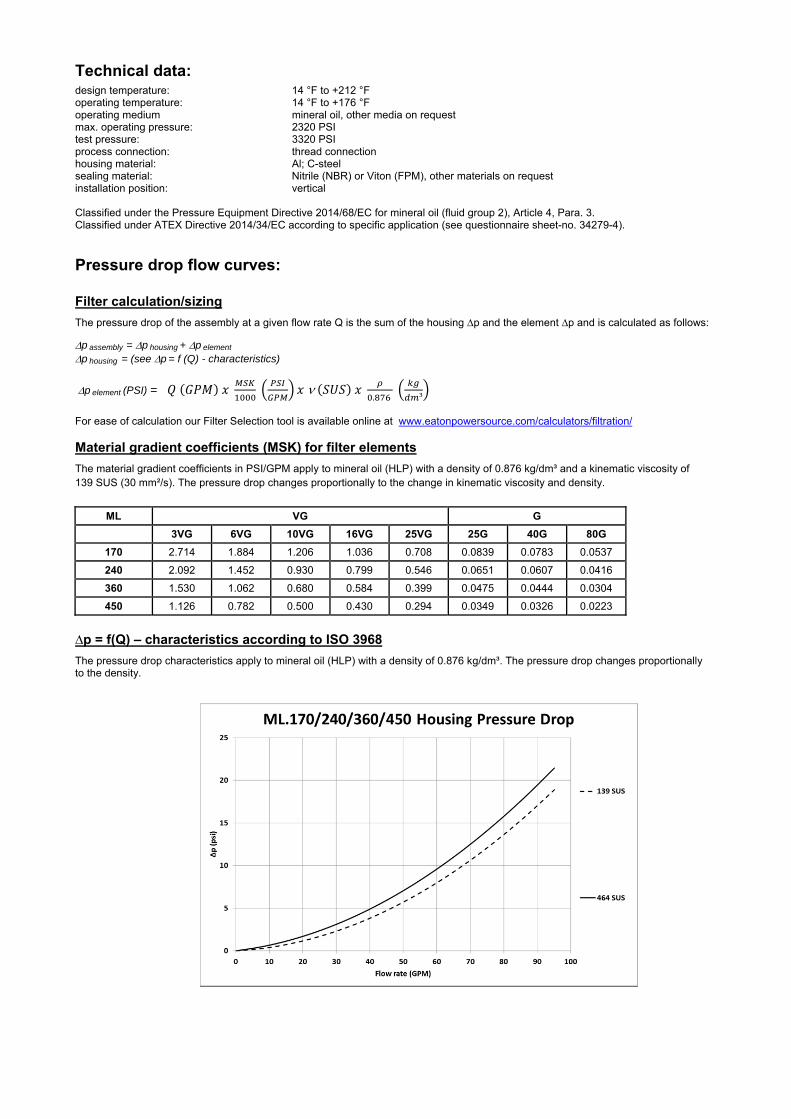
Technical data:
design temperature: 14 °F to +212 °F operating temperature: 14 °F to +176 °F operating medium mineral oil, other media on request max. operating pressure: 2320 PSI test pressure: 3320 PSI process connection: thread connection housing material: Al; C-steel sealing material: Nitrile (NBR) or Viton (FPM), other materials on request installation position: vertical
Classified under the Pressure Equipment Directive 2014/68/EC for mineral oil (fluid group 2), Article 4, Para. 3. Classified under ATEX Directive 2014/34/EC according to specific application (see questionnaire sheet-no. 34279-4).
Pressure drop flow curves:
Filter calculation/sizing
The pressure drop of the assembly at a given flow rate Q is the sum of the housing ∆p and the element ∆p and is calculated as follows:
p assembly = p housing + p element p housing = (see p = f (Q) - characteristics)
p element (PSI) = .
³
For ease of calculation our Filter Selection tool is available online at www.eatonpowersource.com/calculators/filtration/
Material gradient coefficients (MSK) for filter elements
The material gradient coefficients in PSI/GPM apply to mineral oil (HLP) with a density of 0.876 kg/dm³ and a kinematic viscosity of 139 SUS (30 mm²/s). The pressure drop changes proportionally to the change in kinematic viscosity and density.
ML VG G
3VG 6VG 10VG 16VG 25VG 25G 40G 80G
170 2.714 1.884 1.206 1.036 0.708 0.0839 0.0783 0.0537
240 2.092 1.452 0.930 0.799 0.546 0.0651 0.0607 0.0416
360 1.530 1.062 0.680 0.584 0.399 0.0475 0.0444 0.0304
450 1.126 0.782 0.500 0.430 0.294 0.0349 0.0326 0.0223
∆p = f(Q) – characteristics according to ISO 3968
The pressure drop characteristics apply to mineral oil (HLP) with a density of 0.876 kg/dm³. The pressure drop changes proportionally to the density.

Symbols: without indicator with electric
indicator AE 30 and AE 40
with visual-electric indicator
AE 50 and AE 62
with visual-electric indicator
AE 70 and AE 80
with visual indicator
AOR/AOC
with electronic clogging sensor
VS5
filter without internal valve
filter with by-pass valve
filter with reversing valve
Spare parts: item qty. designation dimension article-no.
ML 170 ML 240 ML 360 ML 450 1 1 filter element 01E. 170… 01E.240… 01E.360… 01E.450… 2 1 O-ring 34 x 3,5 304338 (NBR) 304730 (FPM) 3 1 O-ring 75 x 3 302215 (NBR) 304729 (FPM) 4 1 support ring 81 x 2,6 x 1 304581 5 1 clogging indicator visual AOR or AOC see sheet-no. 1606 6 1 clogging indicator visual-electric AE see sheet-no. 1615 7 1 clogging sensor electronic VS5 see sheet-no. 1619 8 1 O-ring 15 x 1,5 315357 (NBR) 315427 (FPM) 9 1 O-ring 22 x 2 304708 (NBR) 304721 (FPM)
10 1 O-ring 14 x 2 304342 (NBR) 304722 (FPM) 11 1 screw plug 20913-4 309817
item 11 execution only without clogging indicator or clogging sensor
Test methods: Filter elements are tested according to the following ISO standards:
ISO 2941 Verification of collapse/burst resistance ISO 2942 Verification of fabrication integrity ISO 2943 Verification of material compatibility with fluids ISO 3723 Method for end load test ISO 3724 Verification of flow fatigue characteristics ISO 3968 Evaluation of pressure drop versus flow characteristics ISO 16889 Multi-pass method for evaluating filtration performance
North America 44 Apple Street Tinton Falls, NJ 07724
Toll Free: 800 656-3344 (North America only)
Tel: +1 732 212-4700 Europe/Africa/Middle East Auf der Heide 2 53947 Nettersheim, Germany
Tel: +49 2486 809-0
Friedensstraße 41 68804 Altlußheim, Germany
Tel: +49 6205 2094-0
An den Nahewiesen 24 55450 Langenlonsheim, Germany
Tel: +49 6704 204-0
China No. 3, Lane 280, Linhong Road Changning District, 200335 Shanghai, P.R. China
Tel: +86 21 5200-0099 Singapore 4 Loyang Lane #04-01/02 Singapore 508914
Tel: +65 6825-1668 Brazil Av. Julia Gaioli, 474 – Bonsucesso 07251-500 – Guarulhos, Brazil
Tel: +55 11 2465-8822
For more information, please email us at [email protected]
or visit www.eaton.com/filtration
© 2015 Eaton. All rights reserved. All trademarks and registered trademarks are the property of their respective owners. All information and recommendations appearing in this brochure concerning the use of products described herein are based on tests believed to be reliable. However, it is the user’s responsibility to determine the suitability for his own use of such products. Since the actual use by others is beyond our control, no guarantee, expressed or implied, is made by Eaton as to the effects of such use or the results to be obtained. Eaton assumes no liability arising out of the use by others of such products. Nor is the information herein to be construed as absolutely complete, since additional information may be necessary or desirable when particular or exceptional conditions or circumstances exist or because of applicable laws or government regulations.

Series ML/MLO 30
2320 PSI
PRESSURE FILTER
Sheet No. 1417 H
EDV 09/15
Weight without indicator: approx. 2.50 lbs. Weight with indicator: approx. 2.90 lbs
Dimensions: inches
Designs and performance values are subject to change.

Pressure Filter
Series ML/MLO 30
2320 PSI
Description: Pressure filter series ML30 and MLO30, have a working pressure up to 2320 PSI. Pressure peaks can be absorbed with a sufficient safety margin. The Filter is in-line mounted.
The filter element consists of star-shaped, pleated filter material, which is supported on the inside by a perforated core tube and is bonded to the end caps with a high-quality adhesive. The flow direction is from outside to inside. Filter elements are available down to 4 µm(c).
Eaton filter elements are known for high intrinsic stability and an excellent filtration capability, a high dirt-retaining capacity and a long service life.
Eaton filter elements are suitable for all petroleum based fluids, HW-emulsions, most synthetic hydraulic fluids and lubrication oils.
Eaton filter elements are available up to a pressure resistance of p 2320 PSI and a rupture strength ofp 3625 PSI.
1. Type index:
1.1. Complete filter: (ordering example)
ML. 30. 10VG. HR. E. P. -. UG. 1. -. AE1 2 3 4 5 6 7 8 9 10 11
1 series: ML = in-line filter-medium pressure range with indicator MLO = in-line filter-medium pressure range without indicator
2 nominal size: 30
3 filter-material and filter-fineness: 80G, 40G, 25G, 10G stainless steel wire mesh 25VG, 16VG, 10VG, 6VG, 3VG microglass
4 filter element collapse rating: 30 = p 435 PSI HR = p 2320 PSI (rupture strength p 3625 PSI)
5 filter element design: E = single-end open
6 sealing material: P = Nitrile (NBR) V = Viton (FPM)
7 filter element specification: (see catalog) - = standard VA = stainless steel IS06 = for HFC applications, see sheet-no. 31601
8 process connection: UG = thread connection
9 process connection size: 1 = -6 SAE
10 filter housing specification: (see catalog) - = standard IS06 = for HFC application, see sheet-no. 31605
11 clogging indicator or clogging sensor: series MLO: - = without series ML: AOR = visual, see sheet-no. 1606 AOC = visual, see sheet-no. 1606 AE = visual-electric, see sheet-no. 1615 VS5 = electronic, see sheet-no. 1619
To add an indicator to your filter, use the corresponding indicator data sheet to find the indicator details and add them to the filter assembly model code.
1.2. Filter element: (ordering example)
01E. 30. 10VG. HR. E. P. - 1 2 3 4 5 6 7
1 series: 01E. = filter element according to company standard
2 nominal size: 30
3 - 7 see type index-complete filter

Technical data:
design temperature: 14 °F to +212 °F operating temperature: 14 °F to +176 °F operating medium mineral oil, other media on request max. operating pressure: 2320 PSI test pressure: 3318 PSI process connection: thread connection housing material: Al, C-steel sealing material: Nitrile (NBR) or Viton (FPM), other materials on request installation position: vertical volume tank: .02 Gal
Classified under the Pressure Equipment Directive 2014/68/EC for mineral oil (fluid group 2), Article 4, Para. 3. Classified under ATEX Directive 2014/34/EC according to specific application (see questionnaire sheet-no. 34279-4).
Pressure drop flow curves: Filter calculation/sizing
The pressure drop of the assembly at a given flow rate Q is the sum of the housing ∆p and the element ∆p and is calculated as follows:
p assembly = p housing + p element p housing = (see p = f (Q) - characteristics)
p element (PSI) = .
³
For ease of calculation our Filter Selection tool is available online at www.eatonpowersource.com/calculators/filtration/
Material gradient coefficients (MSK) for filter elements
The material gradient coefficients in psi/gpm apply to mineral oil (HLP) with a density of 0.876 kg/dm³ and a kinematic viscosity of 139 SUS (30 mm²/s). The pressure drop changes proportionally to the change in kinematic viscosity and density.
ML/MLO VG G
3VG 6VG 10VG 16VG 25VG 25G 40G 80G
30 12.554 8.716 5.580 4.794 3.275 0.2539 0.2369 0.1623
∆p = f(Q) – characteristics according to ISO 3968
The pressure drop characteristics apply to mineral oil (HLP) with a density of 0.876 kg/dm³. The pressure drop changes proportionally to the density.

Symbols: without indicator with electric
indicator AE 30 and AE 40
with visual-electric indicator
AE 50 and AE 62
with visual-electric indicator
AE 70 and AE 80
with visual indicator
AOR/AOC
with electronic clogging sensor
VS5
Spare parts: item qty. designation dimension article-no.
1 1 filter element 01E.30… 2 1 O-ring 11 x 3 312603 (NBR) 312727 (FPM) 3 1 O-ring 32 x 2,5 306843 (NBR) 308268 (FPM) 4 1 support ring 37 x 2,1 x 1 305466 5 1 clogging indicator, visual AOR or AOC see sheet-no. 1606 6 1 clogging indicator, visual-electric AE see sheet-no. 1615 7 1 clogging sensor, electronic VS5 see sheet-no. 1619 8 1 O-ring 15 x 1,5 315357 (NBR) 315427 (FPM) 9 1 O-ring 22 x 2 304708 (NBR) 304721 (FPM)
10 1 O-ring 14 x 2 304342 (NBR) 304722 (FPM)
Test methods: Filter elements are tested according to the following ISO standards:
ISO 2941 Verification of collapse/burst resistance ISO 2942 Verification of fabrication integrity ISO 2943 Verification of material compatibility with fluids ISO 3723 Method for end load test ISO 3724 Verification of flow fatigue characteristics ISO 3968 Evaluation of pressure drop versus flow characteristics ISO 16889 Multi-pass method for evaluating filtration performance
North America 44 Apple Street Tinton Falls, NJ 07724
Toll Free: 800 656-3344 (North America only)
Tel: +1 732 212-4700 Europe/Africa/Middle East Auf der Heide 2 53947 Nettersheim, Germany
Tel: +49 2486 809-0
Friedensstraße 41 68804 Altlußheim, Germany
Tel: +49 6205 2094-0
An den Nahewiesen 24 55450 Langenlonsheim, Germany
Tel: +49 6704 204-0
China No. 3, Lane 280, Linhong Road Changning District, 200335 Shanghai, P.R. China
Tel: +86 21 5200-0099 Singapore 4 Loyang Lane #04-01/02 Singapore 508914
Tel: +65 6825-1668 Brazil Av. Julia Gaioli, 474 – Bonsucesso 07251-500 – Guarulhos, Brazil
Tel: +55 11 2465-8822
For more information, please email us at [email protected]
or visit www.eaton.com/filtration
© 2015 Eaton. All rights reserved. All trademarks and registered trademarks are the property of their respective owners. All information and recommendations appearing in this brochure concerning the use of products described herein are based on tests believed to be reliable. However, it is the user’s responsibility to determine the suitability for his own use of such products. Since the actual use by others is beyond our control, no guarantee, expressed or implied, is made by Eaton as to the effects of such use or the results to be obtained. Eaton assumes no liability arising out of the use by others of such products. Nor is the information herein to be construed as absolutely complete, since additional information may be necessary or desirable when particular or exceptional conditions or circumstances exist or because of applicable laws or government regulations.

Series MNL 40-100
2320 PSI
PRESSURE FILTER
Sheet No. 1427 H
EDV 09/15
1) Connect the stand grounding tab to a suitable earth ground point.
Dimensions: inches Designs and performance values are subject to change.
Dimensions:
type MNL 40 MNL 63 MNL100
connection -8 SAE -12 SAE -16 SAE
A 7.17 9.53 13.07
B 8.26 10.62 14.17
weight 4.41 lbs. 5.51 lbs. 7.28 lbs.
volume tank .06 Gal. .09 Gal. .14 Gal.

Pressure Filter
Series MNL 40-100
2320 PSI
Description: Pressure filter series MNL 40-100 have a working pressure up to 2320 PSI. Pressure peaks can be absorbed with a sufficient safety margin. The MNL-filters is in-line mounted.
The filter element consists of star-shaped, pleated filter material, which is supported on the inside by a perforated core tube and is bonded to the end caps with a high-quality adhesive. The flow direction is from outside to inside. Filter elements are available down to 5 µm(c). Finer filtration is available upon request.
Eaton filter elements are known for high intrinsic stability and an excellent filtration capability, a high dirt-retaining capacity and a long service life.
Eaton filter elements are suitable for all petroleum based fluids, HW-emulsions, most synthetic hydraulic fluids and lubrication oils.
Eaton filter elements are available up to a pressure resistance of p 2320 PSI and a rupture strength ofp 3625 PSI.
The internal valve is integrated into the filter head. After reaching the bypass pressure setting, the bypass valve will send unfiltered partial flow around the filter. The reversing valve provides another level of protection for the filter element. The reverse flow will not be filtered.
1. Type index:
1.1. Complete filter: (ordering example)
MNL. 63. 10VG. HR. E. P. -. UG. 4. -. -. AE1 2 3 4 5 6 7 8 9 10 11 12
1 series: MNL = standard in-line filter-medium pressure range
according to DIN 24550 T1, T2
2 nominal size: 40, 63, 100
3 filter-material and filter-fineness: 80G, 40G, 25G, 10G stainless steel wire mesh 25VG, 16VG, 10VG, 6VG, 3VG microglass
4 filter element collapse rating: 30 = p 435 PSI HR = p 2320 PSI (rupture strength p 3625 PSI)
5 filter element design: E = single-end open
6 sealing material: P = Nitrile (NBR) V = Viton (FPM)
7 filter element specification: (see catalog) - = standard VA = stainless steel IS06 = for HFC applications, see sheet-no. 31601
8 process connection: UG = thread connection
9 process connection size: 3 = -8 SAE 4 = -12 SAE 5 = -16 SAE
10 filter housing specification: (see catalog) - = standard IS06 = for HFC applications, see sheet-no. 31605
11 internal valve: - = without S1 = with by-pass valve p 51 PSI S2 = with by-pass valve p 102 PSI R = reversing valve, Q ≤ 18.50 GPM
12 clogging indicator or clogging sensor: - = without AOR = visual, see sheet-no. 1606 AOC = visual, see sheet-no. 1606 AE = visual-electric, see sheet-no. 1615 VS5 = electronic, see sheet-no. 1619
To add an indicator to your filter, use the corresponding indicator data sheet to find the indicator details and add them to the filter assembly model code.
1.2. Filter element: (ordering example)
01NL. 63. 10VG. HR. E. P. - 1 2 3 4 5 6 7
1 series: 01NL. = filter element according to DIN 24550, T3
2 nominal size: 40, 63, 100
3 - 7 see type index-complete filter

Technical data:
design temperature: 14 °F to +212 °F operating temperature: 14 °F to +176 °F operating medium mineral oil, other media on request max. operating pressure: 2320 PSI test pressure: 3320 PSI process connection: thread connection housing material: aluminum forging alloy; C-steel sealing material: Nitrile (NBR) or Viton (FPM), other materials on request installation position: vertical
Classified under the Pressure Equipment Directive 2014/68/EC for mineral oil (fluid group 2), Article 4, Para. 3. Classified under ATEX Directive 2014/34/EC according to specific application (see questionnaire sheet-no. 34279-4).
Pressure drop flow curves:
Filter calculation/sizing
The pressure drop of the assembly at a given flow rate Q is the sum of the housing ∆p and the element ∆p and is calculated as follows:
p assembly = p housing + p element p housing = (see p = f (Q) - characteristics)
p element (PSI) = .
³
For ease of calculation our Filter Selection tool is available online at www.eatonpowersource.com/calculators/filtration/
Material gradient coefficients (MSK) for filter elements
The material gradient coefficients in PSI/GPM apply to mineral oil (HLP) with a density of 0.876 kg/dm³ and a kinematic viscosity of 139 SUS (30 mm²/s). The pressure drop changes proportionally to the change in kinematic viscosity and density.
MNL VG G
3VG 6VG 10VG 16VG 25VG 25G 40G 80G
40 6.991 4.853 3.107 2.705 1.848 0.1893 0.1766 0.1210
63 4.241 2.926 1.873 1.631 1.114 0.1131 0.1056 0.0723
100 2.640 1.833 1.173 1.021 0.698 0.0699 0.0652 0.0447
∆p = f(Q) – characteristics according to ISO 3968
The pressure drop characteristics apply to mineral oil (HLP) with a density of 0.876 kg/dm³. The pressure drop changes proportionally to the density.

Symbols: without indicator with electric
indicator AE 30 and AE 40
with visual-electric indicator
AE 50 and AE 62
with visual-electric indicator
AE 70 and AE 80
with visual indicator
AOR/AOC
with electronic clogging sensor
VS5 filter without internal valve
filter with by-pass valve
filter with reversing valve
Spare parts: item qty. designation dimension article-no.
MNL 40 MNL 63 MNL 100 1 1 filter element 01NL.40… 01NL.63… 01NL.100… 2 1 O-ring 22 x 3,5 304341 (NBR) 304392 (FPM) 3 1 O-ring 54 x 3 304657 (NBR) 304720 (FPM) 4 1 support ring 60 x 2,6 x 1 311779 5 1 clogging indicator visual AOR or AOC see sheet-no. 1606 6 1 clogging indicator visual-electric AE see sheet-no. 1615 7 1 clogging sensor electronic VS5 see sheet-no. 1619 8 1 O-ring 15 x 1,5 315357 (NBR) 315427 (FPM) 9 1 O-ring 22 x 2 304708 (NBR) 304721 (FPM)
10 1 O-ring 14 x 2 304342 (NBR) 304722 (FPM) 11 1 screw plug 20913-4 309817
item 11 execution only without clogging indicator or clogging sensor
Test methods: Filter elements are tested according to the following ISO standards:
ISO 2941 Verification of collapse/burst resistance ISO 2942 Verification of fabrication integrity ISO 2943 Verification of material compatibility with fluids ISO 3723 Method for end load test ISO 3724 Verification of flow fatigue characteristics ISO 3968 Evaluation of pressure drop versus flow characteristics ISO 16889 Multi-pass method for evaluating filtration performance
North America 44 Apple Street Tinton Falls, NJ 07724
Toll Free: 800 656-3344 (North America only)
Tel: +1 732 212-4700 Europe/Africa/Middle East Auf der Heide 2 53947 Nettersheim, Germany
Tel: +49 2486 809-0
Friedensstraße 41 68804 Altlußheim, Germany
Tel: +49 6205 2094-0
An den Nahewiesen 24 55450 Langenlonsheim, Germany
Tel: +49 6704 204-0
China No. 3, Lane 280, Linhong Road Changning District, 200335 Shanghai, P.R. China
Tel: +86 21 5200-0099 Singapore 4 Loyang Lane #04-01/02 Singapore 508914
Tel: +65 6825-1668 Brazil Av. Julia Gaioli, 474 – Bonsucesso 07251-500 – Guarulhos, Brazil
Tel: +55 11 2465-8822
For more information, please email us at [email protected]
or visit www.eaton.com/filtration
© 2015 Eaton. All rights reserved. All trademarks and registered trademarks are the property of their respective owners. All information and recommendations appearing in this brochure concerning the use of products described herein are based on tests believed to be reliable. However, it is the user’s responsibility to determine the suitability for his own use of such products. Since the actual use by others is beyond our control, no guarantee, expressed or implied, is made by Eaton as to the effects of such use or the results to be obtained. Eaton assumes no liability arising out of the use by others of such products. Nor is the information herein to be construed as absolutely complete, since additional information may be necessary or desirable when particular or exceptional conditions or circumstances exist or because of applicable laws or government regulations.

Series MDV 40-63
2900 PSI
PRESSURE FILTER
Sheet No. 1419 F
EDV 09/15
Dimensions: inches Designs and performance values are subject to change.
Dimensions:
type MDV 40 MDV 63 connection - 8 SAE -12 SAE
A 8.30 10.67 B 6.18 8.54 C 10.43 12.80
weight approx. 5.94 lbs. 7.04 lbs. volume tank 0.06 Gal. 0.09 Gal.
.

Pressure Filter
Series MDV 40-63
2900 PSI
Description: Pressure filter series MDV have a working pressure up to 2900 PSI. The pressure peaks are absorbed by a sufficient margin of safety. The MDV-filter is in-line mounted.
The filter element meets DIN 24550T3 and consists of star-shaped, pleated filter material which is supported on the inside by a perforated core tube and is bonded to the end caps with a high-quality adhesive. The flow direction is from outside to the inside. Filter elements are available down to 5 µm(c). Finer filtration is available upon request.
Eaton filter elements are known for high intrinsic stability and an excellent filtration capability, a high dirt-retaining capacity and a long service life.
Eaton filter elements are suitable for all petroleum based fluids, HW-emulsions, most synthetic hydraulic fluids and lubrication oils.
Eaton filter elements are available up to a pressure resistance of p 2320 PSI and a rupture strength ofp 3625 PSI.
The internal valve is integrated into the filter head. The differential pressure valve diverts the contaminated fluid to the tank when the element is clogged. During cold start, the differential pressure valve will divert the fluid to the tank until the system warms up.
1. Type index:
1.1. Complete filter: (ordering example)
MDV. 40. 10VG. HR. E. P. -. UG. 3. -. D2.AE1 2 3 4 5 6 7 8 9 10 11 12
1 series: MDV = medium pressure filter with differential pressure-valve
2 nominal size: 40, 63
3 filter-material and filter-fineness: 80G, 40G, 25G stainless steel wire mesh 25VG, 16VG, 10VG, 6VG, 3VG microglass
4 filter element collapse rating: 30 = p 435 PSI HR = p 2320 PSI (rupture strength p 3625 PSI)
5 filter element design: E = single-end open
6 sealing material: P = Nitrile (NBR) V = Viton (FPM)
7 filter element specification: - = standard VA = stainless steel
8 process connection: UG = thread connection
9 process connection size: 3 = -8 SAE 4 = -12 SAE
10 filter housing specification: - = standard
11 internal valve: D1 = differential pressure-valve p 51 PSI D2 = differential pressure-valve p 102 PSI
12 clogging indicator or clogging sensor: - = without AOR = visual, see sheet-no. 1606 AOC = visual, see sheet-no. 1606 AE = visual-electric, see sheet-no. 1615 VS5 = electronic, see sheet-no. 1619
To add an indicator to your filter, use the corresponding indicator data sheet to find the indicator details and add them to the filter assembly model code.
1.2. Filter element: (ordering example)
01NL. 40. 10VG. HR. E. P. - 1 2 3 4 5 6 7
1 series: 01NL. = standard filter element according to DIN 24550, T3
2 nominal size: 40, 63
3 - 7 see type index-complete filter
.
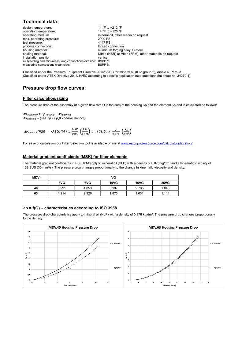
Technical data:
design temperature: 14 °F to +212 °F operating temperature: 14 °F to +176 °F operating medium mineral oil, other media on request max. operating pressure: 2900 PSI test pressure: 4147 PSI process connection: thread connection housing material: aluminum forging alloy, C-steel sealing material: Nitrile (NBR) or Viton (FPM), other materials on request installation position: vertical air bleeding and mini-measuring connections dirt side: BSPP ¼ measuring connections clean side: BSPP ½
Classified under the Pressure Equipment Directive 2014/68/EC for mineral oil (fluid group 2), Article 4, Para. 3. Classified under ATEX Directive 2014/34/EC according to specific application (see questionnaire sheet-no. 34279-4).
Pressure drop flow curves:
Filter calculation/sizing
The pressure drop of the assembly at a given flow rate Q is the sum of the housing ∆p and the element ∆p and is calculated as follows:
p assembly = p housing + p element p housing = (see p = f (Q) - characteristics)
p element (PSI) = .
³
For ease of calculation our Filter Selection tool is available online at www.eatonpowersource.com/calculators/filtration/
Material gradient coefficients (MSK) for filter elements
The material gradient coefficients in PSI/GPM apply to mineral oil (HLP) with a density of 0.876 kg/dm³ and a kinematic viscosity of 139 SUS (30 mm²/s). The pressure drop changes proportionally to the change in kinematic viscosity and density.
MDV VG
3VG 6VG 10VG 16VG 25VG
40 6.991 4.853 3.107 2.705 1.848
63 4.214 2.926 1.873 1.631 1.114
∆p = f(Q) – characteristics according to ISO 3968
The pressure drop characteristics apply to mineral oil (HLP) with a density of 0.876 kg/dm³. The pressure drop changes proportionally to the density.

Symbols:
without indicator with electric indicator
AE 30 and AE 40 with visual-electric
indicator AE 50 and AE 62
with visual-electric indicator
AE 70 and AE 80
with visual indicator
AOR/AOC
with electronic clogging sensor
VS5
Spare parts:
item qty. designation dimension article-no. MDV 40 MDV 63
1 1 filter element 01NL.40… 01NL.63… 2 1 O-ring 22 x 3,5 304341 (NBR) 304392 (FPM) 3 1 O-ring 54 x 3 304657 (NBR) 304720 (FPM) 4 1 support ring 60 x 2,6 x 1 311779 5 1 screw plug ½ BSPP 304678 6 1 clogging indicator visual AOR or AOC see sheet-no. 1606 7 1 clogging indicator visual-electric AE see sheet-no. 1615 8 1 clogging sensor electronic VS5 see sheet-no. 1619 9 1 O-ring 15 x 1,5 315357 (NBR) 315427 (FPM)
10 1 O-ring 22 x 2 304708 (NBR) 304721 (FPM) 11 1 O-ring 14 x 2 304342 (NBR) 304722 (FPM) 12 1 screw plug 20913-4 309817
item 12 execution only without clogging indicator or clogging sensor
Test methods: Filter elements are tested according to the following ISO standards:
ISO 2941 Verification of collapse/burst resistance ISO 2942 Verification of fabrication integrity ISO 2943 Verification of material compatibility with fluids ISO 3723 Method for end load test ISO 3724 Verification of flow fatigue characteristics ISO 3968 Evaluation of pressure drop versus flow characteristics ISO 16889 Multi-pass method for evaluating filtration performance
North America 44 Apple Street Tinton Falls, NJ 07724
Toll Free: 800 656-3344 (North America only)
Tel: +1 732 212-4700 Europe/Africa/Middle East Auf der Heide 2 53947 Nettersheim, Germany
Tel: +49 2486 809-0
Friedensstraße 41 68804 Altlußheim, Germany
Tel: +49 6205 2094-0
An den Nahewiesen 24 55450 Langenlonsheim, Germany
Tel: +49 6704 204-0
China No. 3, Lane 280, Linhong Road Changning District, 200335 Shanghai, P.R. China
Tel: +86 21 5200-0099 Singapore 4 Loyang Lane #04-01/02 Singapore 508914
Tel: +65 6825-1668 Brazil Av. Julia Gaioli, 474 – Bonsucesso 07251-500 – Guarulhos, Brazil
Tel: +55 11 2465-8822
For more information, please email us at [email protected]
or visit www.eaton.com/filtration
© 2015 Eaton. All rights reserved. All trademarks and registered trademarks are the property of their respective owners. All information and recommendations appearing in this brochure concerning the use of products described herein are based on tests believed to be reliable. However, it is the user’s responsibility to determine the suitability for his own use of such products. Since the actual use by others is beyond our control, no guarantee, expressed or implied, is made by Eaton as to the effects of such use or the results to be obtained. Eaton assumes no liability arising out of the use by others of such products. Nor is the information herein to be construed as absolutely complete, since additional information may be necessary or desirable when particular or exceptional conditions or circumstances exist or because of applicable laws or government regulations.

Series LF 63
363 PSI
PRESSURE FILTER
Sheet No. 1109 J
EDV 09/15
Weight: approx. 4.40 lbs.
Dimensions: inches Designs and performance values are subject to change.

1. Type index:
1.1. Complete filter: (ordering example)
LF. 63. 10VG. 30. E. P. -. UG. 4. -. -. AE1 2 3 4 5 6 7 8 9 10 11 12
1 series: LF = In-line filter
2 nominal size: 63
3 filter-material and filter-fineness: 80G, 40G, 25G, 10G stainless steel wire mesh 25VG, 16VG, 10VG, 6VG, 3VG microglass
4 filter element collapse rating: 30 = p 435 PSI
5 filter element design: E = single-end open
6 sealing material: P = Nitrile (NBR) V = Viton (FPM)
7 filter element specification: (see catalog) - = standard VA = stainless steel IS06 = for HFC applications, see sheet-no. 31601 IS07 = for oil/amonia mixtures (NH3), see sheet-no. 31602
8 process connection: UG = thread connection
9 process connection size: 4 = -12 SAE
10 filter housing specification: (see catalog) - = standard IS06 = for HFC applications, see sheet-no. 31605
11 internal valve: - = without S1 = with by-pass valve p 51 PSI
12 clogging indicator or clogging sensor: - = without AOR = visual, see sheet-no. 1606 AOC = visual, see sheet-no. 1606 AE = visual-electric, see sheet-no. 1615 VS5 = electronic, see sheet-no. 1619
To add an indicator to your filter, use the corresponding indicator data sheet to find the indicator details and add them to the filter assembly model code.
1.2. Filter element: (ordering example)
01NL. 63. 10VG. 30. E. P. - 1 2 3 4 5 6 7
1 series: 01NL. = standard filter element according to DIN 24550, T3
2 nominal size: 63
3 - 7 see type index-complete filter
Pressure Filter
Series LF 63
363 PSI
Description: In-line filter series LF 63 have a working pressure up to 363 PSI. Pressure peaks can be absorbed with a sufficient safety margin. The LF filter is mounted in-line.It can be used as suction filter, pressure filter and return-line filter.
The filter element consists of star-shaped, pleated filter material which is supported on the inside by a perforated core tube and is bonded to the end caps with a high-quality adhesive. The flow direction is from outside to inside.
For cleaning the mesh element or changing the glass fiber element, remove the cover and take out the element. The mesh elements are not guaranteed to maintain 100% performance after cleaning.
For filtration finer than 40 μm, use the disposable elements made of microglass. Filter elements as fine as 5 μm(c) are available; finer filter elements upon request.
Eaton-filter elements are known for a high intrinsic stability and an excellent filtration capability, a high dirt-retaining capacity and a long service life.
Eaton filter elements are suitable for all petroleum based fluids, HW-emulsions, most synthetic hydraulic fluids and lubrication oils.
The by-pass valve is integrated into the filter head. After reaching the by-pass pressure setting, the by-pass valve will send unfiltered partial flow around the filter. Ship classifications available upon request.

Technical data:
design temperature: 14 °F to +212 °F operating temperature: 14 °F to +176 °F operating medium mineral oil, other media on request max. operating pressure: 363 PSI test pressure: 522 PSI process connection: thread connection housing material: aluminium-cast sealing material: Nitrile (NBR) or Viton (FPM), other materials on request installation position: vertical measure connections: BSPP ¼ drain- and bleeder connections: BSPP ½ volume tank: .18 Gal.
Classified under the Pressure Equipment Directive 2014/68/EC for mineral oil (fluid group 2), Article 4, Para. 3. Classified under ATEX Directive 2014/34/EC according to specific application (see questionnaire sheet-no. 34279-4).
Pressure drop flow curves:
Filter calculation/sizing
The pressure drop of the assembly at a given flow rate Q is the sum of the housing ∆p and the element ∆p and is calculated as follows:
p assembly = p housing + p element p housing = (see p = f (Q) - characteristics)
p element (PSI) = .
³
For ease of calculation our Filter Selection tool is available online at www.eatonpowersource.com/calculators/filtration/
Material gradient coefficients (MSK) for filter elements
The material gradient coefficients in psi/gpm apply to mineral oil (HLP) with a density of 0.876 kg/dm³ and a kinematic viscosity of 139 SUS (30 mm²/s). The pressure drop changes proportionally to the change in kinematic viscosity and density.
LF VG G
3VG 6VG 10VG 16VG 25VG 25G 40G 80G
63 4.214 2.926 1.873 1.631 11.4 0.1131 0.1056 0.0723
∆p = f(Q) – characteristics according to ISO 3968
The pressure drop characteristics apply to mineral oil (HLP) with a density of 0.876 kg/dm³. The pressure drop changes proportionally to the density.

Symbols: without indicator with electric
indicator AE 30 and AE 40
with visual-electric indicator
AE 50 and AE 62
with visual-electric indicator
AE 70 and AE 80
with visual indicator
AOR/AOC
with electronic clogging sensor
VS5 filter without internal valve
filter with by-pass valve
Spare parts: item qty. designation dimension article-no.
1 1 filter element 01NL.63… 2 1 O-ring 22 x 3,5 304341 (NBR) 304392 (FPM) 3 1 O-ring 56 x 3 305072 (NBR) 305322 (FPM) 4 1 O-ring 48 x 3 304357 (NBR) 304404 (FPM) 5 1 screw plug ½ BSPP 304678 6 1 clogging indicator, visual AOR or AOC see sheet-no. 1606 7 1 clogging indicator, visual-electrical AE see sheet-no. 1615 8 1 clogging sensor, electronical VS5 see sheet-no. 1619 9 1 O-ring 15 x 1,5 315357 (NBR) 315427 (FPM)
10 1 O-ring 22 x 2 304708 (NBR) 304721 (FPM) 11 1 O-ring 14 x 2 304342 (NBR) 304722 (FPM) 12 2 screw plug 1 /8 BSPP 305496
item 12 execution only without clogging indicator or clogging sensor
Test methods: Filter elements are tested according to the following ISO standards:
ISO 2941 Verification of collapse/burst resistance ISO 2942 Verification of fabrication integrity ISO 2943 Verification of material compatibility with fluids ISO 3723 Method for end load test ISO 3724 Verification of flow fatigue characteristics ISO 3968 Evaluation of pressure drop versus flow characteristics ISO 16889 Multi-pass method for evaluating filtration performance
North America 44 Apple Street Tinton Falls, NJ 07724
Toll Free: 800 656-3344 (North America only)
Tel: +1 732 212-4700 Europe/Africa/Middle East Auf der Heide 2 53947 Nettersheim, Germany
Tel: +49 2486 809-0
Friedensstraße 41 68804 Altlußheim, Germany
Tel: +49 6205 2094-0
An den Nahewiesen 24 55450 Langenlonsheim, Germany
Tel: +49 6704 204-0
China No. 3, Lane 280, Linhong Road Changning District, 200335 Shanghai, P.R. China
Tel: +86 21 5200-0099 Singapore 4 Loyang Lane #04-01/02 Singapore 508914
Tel: +65 6825-1668 Brazil Av. Julia Gaioli, 474 – Bonsucesso 07251-500 – Guarulhos, Brazil
Tel: +55 11 2465-8822
For more information, please email us at [email protected]
or visit www.eaton.com/filtration
© 2015 Eaton. All rights reserved. All trademarks and registered trademarks are the property of their respective owners. All information and recommendations appearing in this brochure concerning the use of products described herein are based on tests believed to be reliable. However, it is the user’s responsibility to determine the suitability for his own use of such products. Since the actual use by others is beyond our control, no guarantee, expressed or implied, is made by Eaton as to the effects of such use or the results to be obtained. Eaton assumes no liability arising out of the use by others of such products. Nor is the information herein to be construed as absolutely complete, since additional information may be necessary or desirable when particular or exceptional conditions or circumstances exist or because of applicable laws or government regulations.

Series LF 101
464 PSI
PRESSURE FILTER
Sheet No. 1125 D
EDV 09/15
Weight: approx. 8.0 lbs.
Dimensions: inches Designs and performance values are subject to change.

Pressure Filter
Series LF 101
464 PSI
Description: In-line filters series LF 101 have a working pressure up to 464 PSI. Pressure peaks can be absorbed with a sufficient safety margin. The LF filter is mounted in-line.It can be used as suction filter, pressure filter and return-line filter.
The filter element consists of star-shaped, pleated filter material which is supported on the inside by a perforated core tube and is bonded to the end caps with a high-quality adhesive. The flow direction is from outside to inside.
For cleaning the mesh element or changing the glass fiber element, remove the cover and take out the element. The mesh elements are not guaranteed to maintain 100% performance after cleaning.
For filtration finer than 40 μm, use the disposable elements made of microglass. Filter elements as fine as 5 μm(c) are available; finer filter elements upon request.
Eaton filter elements are known for a high intrinsic stability and an excellent filtration capability, a high dirt-retaining capacity and a long service life.
Eaton filter elements are suitable for all petroleum based fluids, HW-emulsions, most synthetic hydraulic fluids and lubrication oils.
Ship classifications available upon request.
1. Type index:
1.1. Complete filter: (ordering example)
LF. 101. 10VG. 16. E. P. -. UG. 5. -. AE1 2 3 4 5 6 7 8 9 10 11
1 series: LF = In-line filter
2 nominal size: 101
3 filter-material and filter-fineness: 80G, 40G, 25G, 10G stainless steel wire mesh 25VG, 16VG, 10VG, 6VG, 3VG microglass 25API, 10API microglass according to API
4 filter element collapse rating: 16 = p 232 PSI
5 filter element design: E = single-end open S = with by-pass valve p 29 PSI S1 = with by-pass valve p 51 PSI
6 sealing material: P = Nitrile (NBR) V = Viton (FPM)
7 filter element specification: (see catalog) - = standard VA = stainless steel IS06 = for HFC applications, see sheet-no. 31601 IS07 = for oil/amonia mixtures (NH3), see sheet-no. 31602
8 process connection: UG = thread connection
9 process connection size: 5 = -16 SAE
10 filter housing specification: (see catalog) - = standard IS06 = for HFC applications, see sheet-no. 31605
11 clogging indicator or clogging sensor: - = without AE = visual-electric, see sheet-no. 1609 OP = visual, see sheet-no. 1628 OE = visual-electric, see sheet-no. 1628 VS5 = electronic, see sheet-no. 1641
To add an indicator to your filter, use the corresponding indicator data sheet to find the indicator details and add them to the filter assembly model code.
1.2. Filter element: (ordering example)
01N. 100. 10VG. 16. E. P. - 1 2 3 4 5 6 7
1 series: 01N. = filter element according to company standard
2 nominal size: 100
3 - 7 see type index-complete filter
.

Technical data:
design temperature: 14 °F to +212 °F operating temperature: 14 °F to +176 °F operating medium mineral oil, other media on request max. operating pressure: 464 PSI test pressure: 900 PSI process connection: thread connection housing material: aluminium-cast sealing material: Nitrile (NBR) or Viton (FPM), other materials on request installation position: vertical measure connections: BSPP ¼ drain- and bleeder connections: BSPP ½ volume tank: .26 Gal.
Classified under the Pressure Equipment Directive 2014/68/EC for mineral oil (fluid group 2), Article 4, Para. 3. Classified under ATEX Directive 2014/34/EC according to specific application (see questionnaire sheet-no. 34279-4).
Pressure drop flow curves:
Filter calculation/sizing
The pressure drop of the assembly at a given flow rate Q is the sum of the housing ∆p and the element ∆p and is calculated as follows:
p assembly = p housing + p element p housing = (see p = f (Q) - characteristics)
p element (PSI) = .
³
For ease of calculation our Filter Selection tool is available online at www.eatonpowersource.com/calculators/filtration/
Material gradient coefficients (MSK) for filter elements
The material gradient coefficients in psi/gpm apply to mineral oil (HLP) with a density of 0.876 kg/dm³ and a kinematic viscosity of 139 SUS (30 mm²/s). The pressure drop changes proportionally to the change in kinematic viscosity and density.
LF VG G
3VG 6VG 10VG 16VG 25VG 25G 40G 80G
101 2.473 1.717 1.099 0.957 0.654 0.0651 0.0607 0.0416
∆p = f(Q) – characteristics according to ISO 3968
The pressure drop characteristics apply to mineral oil (HLP) with a density of 0.876 kg/dm³. The pressure drop changes proportionally to the density.

Symbols: without indicator with electric
indicator AE 30 and AE 40
with visual-electric indicator
AE 50 and AE 62
with visual-electric indicator
AE 70 and AE 80
with visual indicator
OP
with visual-electric indicator
OE
with electronic clogging sensor
VS5
Spare parts: item qty. designation dimension article-no.
1 1 filter element 01N.100… 2 1 O-ring 32 x 3,5 304378 (NBR) 304401 (FPM) 3 1 O-ring 76 x 4 305599 (NBR) 310291 (FPM) 4 2 screw plug BSPP ¼ 305003 5 2 screw plug BSPP ½ 304678 6 1 clogging indicator, visual OP see sheet-no. 1628 7 1 clogging indicator, visual-electric OE see sheet-no. 1628 8 1 clogging indicator, visual-electric AE see sheet-no. 1609 9 1 clogging sensor, electronic VS5 see sheet-no. 1641
10 2 O-ring 14 x 2 304342 (NBR) 304722 (FPM) 11 2 screw plug BSPP ¼ 305003
item 11 execution only without clogging indicator or clogging sensor
Test methods: Filter elements are tested according to the following ISO standards:
ISO 2941 Verification of collapse/burst resistance ISO 2942 Verification of fabrication integrity ISO 2943 Verification of material compatibility with fluids ISO 3723 Method for end load test ISO 3724 Verification of flow fatigue characteristics ISO 3968 Evaluation of pressure drop versus flow characteristics ISO 16889 Multi-pass method for evaluating filtration performance
North America 44 Apple Street Tinton Falls, NJ 07724
Toll Free: 800 656-3344 (North America only)
Tel: +1 732 212-4700 Europe/Africa/Middle East Auf der Heide 2 53947 Nettersheim, Germany
Tel: +49 2486 809-0
Friedensstraße 41 68804 Altlußheim, Germany
Tel: +49 6205 2094-0
An den Nahewiesen 24 55450 Langenlonsheim, Germany
Tel: +49 6704 204-0
China No. 3, Lane 280, Linhong Road Changning District, 200335 Shanghai, P.R. China
Tel: +86 21 5200-0099 Singapore 4 Loyang Lane #04-01/02 Singapore 508914
Tel: +65 6825-1668 Brazil Av. Julia Gaioli, 474 – Bonsucesso 07251-500 – Guarulhos, Brazil
Tel: +55 11 2465-8822
For more information, please email us at [email protected]
or visit www.eaton.com/filtration
© 2015 Eaton. All rights reserved. All trademarks and registered trademarks are the property of their respective owners. All information and recommendations appearing in this brochure concerning the use of products described herein are based on tests believed to be reliable. However, it is the user’s responsibility to determine the suitability for his own use of such products. Since the actual use by others is beyond our control, no guarantee, expressed or implied, is made by Eaton as to the effects of such use or the results to be obtained. Eaton assumes no liability arising out of the use by others of such products. Nor is the information herein to be construed as absolutely complete, since additional information may be necessary or desirable when particular or exceptional conditions or circumstances exist or because of applicable laws or government regulations.

Series LF 251-1100
464 PSI
PRESSURE FILTER
Sheet No. 1117 N
EDV 09/15
Dimensions: inches Designs and performance values are subject to change.
Dimensions:
type LF 251 LF 401 LF 631 LF 1001 LF 1100 connection SAE 1 ½“ SAE 2“ SAE 2 ½“ SAE 3“ SAE 5“
A 13.94 21.65 22.09 23.03 25.24 B 10.00 15.91 15.98 15.91 16.93 C 10.24 16.14 16.14 16.14 16.14 D 1.54 3.35 3.39 3.94 5.19 E 3.15 3.15 3.15 3.54 4.57 F - 9.84 9.84 9.84 9.84 G 5.51 5.91 6.69 8.66 8.66 H 5.12 5.12 6.30 8.07 8.07 J 3.15 3.15 3.15 4.57 4.57 K M10x.47 deep M10x.47 deep M12x.71 deep M12x.71 deep M12x.71 deep L 2.64 2.64 3.23 4.17 4.17 M 2.83 2.76 3.39 4.17 4.17 N 1.40 1.68 2.00 2.44 3.62 O 2.75 3.06 3.50 4.19 6.00 P M12x.74deep M10x.74 deep M12x.74 deep M16x.94 deep M16x.94 deep
weight 35 lbs. 55 lbs. 77 lbs. 99 lbs. 112 lbs. volume tank .63 Gal. 1.0 Gal. 1.4 Gal. 3,0 Gal. 3,0 Gal.
1) Connect the stand grounding tab to a suitable earth ground point.

Pressure Filter
Series LF 251-1100
464 PSI
Description: In-line filter series LF 251-1100 have a working pressure up to 464 PSI. Pressure peaks can be absorbed with a sufficient safety margin. The LF filter is mounted in-line.It can be used as suction filter, pressure filter and return-line filter.
The filter element consists of star-shaped, pleated filter material which is supported on the inside by a perforated core tube and is bonded to the end caps with a high-quality adhesive. The flow direction is from outside to inside.
For cleaning the mesh element or changing the glass fiber element, remove the cover and take out the element. The mesh elements are not guaranteed to maintain 100% performance after cleaning.
For filtration finer than 40 μm, use the disposable elements made of microglass. Filter elements as fine as 5 μm(c) are available; finer filter elements upon request.
Eaton-filter elements are known for a high intrinsic stability and an excellent filtration capability, a high dirt-retaining capacity and a long service life.
Eaton filter elements are suitable for all petroleum based fluids, HW-emulsions, most synthetic hydraulic fluids and lubrication oils.
The by-pass valve is integrated into the filter head. After reaching the by-pass pressure setting, the by-pass valve will send unfiltered partial flow around the filter. Ship classifications available upon request.
1. Type index:
1.1. Complete filter: (ordering example)
LF. 401. 10VG. 30. E. P. -. FS. 8. -. -. AE1 2 3 4 5 6 7 8 9 10 11 12
1 series: LF = In-line filter
2 nominal size: 251, 401, 631, 1001, 1100
3 filter-material and filter-fineness: 80G, 40G, 25G, 10G stainless steel wire mesh 25VG, 16VG, 10VG, 6VG, 3VG microglass 25API, 10API microglass according to API
4 filter element collapse rating: 10 = p 145 PSI (01NR.1000) 30 = p 435 PSI (01NL.250-630)
5 filter element design: E = single-end open B = both sides open (01NR.1000) S = with by-pass valve p 29 PSI S1 = with by-pass valve p 51 PSI
6 sealing material: P = Nitrile (NBR) V = Viton (FPM)
7 filter element specification: (see catalog) - = standard VA = stainless steel IS06 = for HFC applications, see sheet-no. 31601 IS07 = for oil/ammonia mixtures (NH3), see sheet-no. 31602
8 process connection: FS = SAE-flange 3000 PSI
9 process connection size: 7 = 1 ½“ (LF251) 8 = 2“ (LF401) 9 = 2 ½“ (LF631) A = 3“ (LF1001) C = 5“ (LF1100)
10 filter housing specification: (see catalog) - = standard IS06 = for HFC applications, see sheet-no. 31605 IS20 = ASME VIII Div.1 with ASME equivalent material,
see sheet-no. 55217 (operating pressure max. 232 PSI)
11 internal valve: - = without S = with by-pass valve p 29 PSI (LF1001/1100) S1 = with by-pass valve p 51 PSI (LF1001/1100)
12 clogging indicator or clogging sensor: - = without AOR = visual, see sheet-no. 1606 AOC = visual, see sheet-no. 1606 AE = visual-electric, see sheet-no. 1609 OP = visual, see sheet-no. 1628 OE = visual-electric, see sheet-no. 1628 VS5 = electronic, see sheet-no. 1641
To add an indicator to your filter, use the corresponding indicator data sheet to find the indicator details and add them to the filter assembly model code. 1.2. Filter element: (ordering example)
01NL. 401. 10VG. 30. E. P. - 1 2 3 4 5 6 7
1 series: 01NL. = standard filter element according to DIN 24550, T3 01NR. = standard return line filter element according to DIN 24550, T4
2 nominal size: 250, 400, 630 (01NL.), 1000 (01NR.)
3 - 7 see type index-complete filter
Accessories: - gauge port - and bleeder connection, see sheet-no. 1650 - drain- and bleeder connection, see sheet-no. 1651 - SAE-counter flange, see sheet-no. 1652

Technical data:
design temperature: 14 °F to +212 °F operating temperature: 14 °F to +176 °F operating medium mineral oil, other media on request max. operating pressure: 464 PSI max. operating pressure at IS20: 232 PSI test pressure: 900 PSI test pressure at IS20: 464 PSI process connection: SAE-flange 3000 PSI housing material: EN-GJS-400-18-LT sealing material: Nitrile (NBR) or Viton (FPM), other materials on request installation position: vertical measure connections: BSPP ¼ drain- and bleeder connections: BSPP ½
Classified under the Pressure Equipment Directive 2014/68/EC for mineral oil (fluid group 2), Article 4, Para. 3. Classified under ATEX Directive 2014/34/EC according to specific application (see questionnaire sheet-no. 34279-4).
Pressure drop flow curves:
Filter calculation/sizing
The pressure drop of the assembly at a given flow rate Q is the sum of the housing ∆p and the element ∆p and is calculated as follows:
p assembly = p housing + p element p housing = (see p = f (Q) - characteristics)
p element (PSI) = .
³
For ease of calculation our Filter Selection tool is available online at www.eatonpowersource.com/calculators/filtration/
Material gradient coefficients (MSK) for filter elements
The material gradient coefficients in psi/gpm apply to mineral oil (HLP) with a density of 0.876 kg/dm³ and a kinematic viscosity of 139 SUS (30 mm²/s). The pressure drop changes proportionally to the change in kinematic viscosity and density.
LF VG G API
3VG 6VG 10VG 16VG 25VG 25G 40G 80G 10API 25API 251 1.14 0.646 0.414 0.360 0.246 0.0277 0.0258 0.0177 0.212 0.097 401 0.700 0.397 0.254 0.221 0.151 0.0169 0.0158 0.0108 0.130 0.059 631 0.534 0.303 0.194 0.169 0.115 0.1417 0.1322 0.0906 0.099 0.045
1001 0.237 0.165 0.105 0.092 0.063 0.0061 0.0057 0.0039 0.053 0.024 1100 0.237 0.165 0.105 0.092 0.063 0.0061 0.0057 0.0039 0.053 0.024
∆p = f(Q) – characteristics according to ISO 3968
The pressure drop characteristics apply to mineral oil (HLP) with a density of 0,876 kg/dm³. The pressure drop changes proportionally to the density.

Symbols: without indicator with electric
indicator AE 30 and AE 40
with visual-electric indicator
AE 50 and AE 62
with visual-electric indicator
AE 70 and AE 80
with visual indicator
AOR/AOC/OP
with visual-electric indicator
OE
with electronic clogging sensor
VS5 filter without internal valve
filter with by-pass valve
Spare parts: item designation qty. dimension
and article-no. qty. dimension
and article-no. qty. dimension
and article-no. qty. dimension
and article-no. LF 251 LF 401 LF 631 LF 1001/1100
1 filter element 1 01NL.250… 1 01NL 400… 1 01NL 630… 1 01NR.1000…
2 O-ring
1
40 x 3 304389 (NBR) 304391 (FPM)
1
40 x 3 304389 (NBR) 304391 (FPM)
1
60 x 3,5 304377 (NBR) 304398 (FPM)
1
90 x 4 306941 (NBR) 307031 (FPM)
3
O-ring
1
115 x 3 303963 (NBR) 307762 (FPM)
1
115 x 3 303963 (NBR) 307762 (FPM)
1
125 x 3 306025 (NBR) 307358 (FPM)
1
185 x 4 305593 (NBR) 306309 (FPM)
4
O-ring (LF 401-1001)
-
-
1
56,75 x 3,53 306035 (NBR) 310264 (FPM)
1
69,45 x 3,53 305868 (NBR) 307357 (FPM)
1
85,32 x 3,53 305590 (NBR) 306308 (FPM)
O-ring (LF 1100)
-
-
-
-
-
-
1
136,12 x 3,53 320162 (NBR) 320163 (FPM)
5
screw plug
3 BSPP ½ 304678
3 BSPP ½ 304678
3 BSPP ½ 304678
3 BSPP ½ 304678
6
screw plug
2 BSPP ¼ 305003
7 clogging indicator, visual 1 AOR or AOC see sheet-no. 1606 8 clogging indicator, visual 1 OP see sheet-no. 1628 9 clogging indicator, visual-electric 1 OE see sheet-no. 1628
10 clogging indicator, visual-electric 1 AE see sheet-no. 1609 11 clogging sensor, electronic 1 VS5 see sheet-no. 1641
12
O-ring
1
15 x 1,5 315357 (NBR) 315427 (FPM)
13
O-ring
1
22 x 2 304708 (NBR) 304721 (FPM)
14
O-ring
2
14 x 2 304342 (NBR) 304722 (FPM)
15 screw plug
2 BSPP ¼ 305003
item 15 execution only without clogging indicator or clogging sensor
Test methods: Filter elements are tested according to the following ISO standards:
ISO 2941 Verification of collapse/burst resistance ISO 2942 Verification of fabrication integrity ISO 2943 Verification of material compatibility with fluids ISO 3723 Method for end load test ISO 3724 Verification of flow fatigue characteristics ISO 3968 Evaluation of pressure drop versus flow characteristics ISO 16889 Multi-pass method for evaluating filtration performance
North America 44 Apple Street Tinton Falls, NJ 07724
Toll Free: 800 656-3344 (North America only)
Tel: +1 732 212-4700 Europe/Africa/Middle East Auf der Heide 2 53947 Nettersheim, Germany
Tel: +49 2486 809-0
Friedensstraße 41 68804 Altlußheim, Germany
Tel: +49 6205 2094-0
An den Nahewiesen 24 55450 Langenlonsheim, Germany
Tel: +49 6704 204-0
China No. 3, Lane 280, Linhong Road Changning District, 200335 Shanghai, P.R. China
Tel: +86 21 5200-0099 Singapore 4 Loyang Lane #04-01/02 Singapore 508914
Tel: +65 6825-1668 Brazil Av. Julia Gaioli, 474 – Bonsucesso 07251-500 – Guarulhos, Brazil
Tel: +55 11 2465-8822
For more information, please email us at [email protected]
or visit www.eaton.com/filtration
© 2015 Eaton. All rights reserved. All trademarks and registered trademarks are the property of their respective owners. All information and recommendations appearing in this brochure concerning the use of products described herein are based on tests believed to be reliable. However, it is the user’s responsibility to determine the suitability for his own use of such products. Since the actual use by others is beyond our control, no guarantee, expressed or implied, is made by Eaton as to the effects of such use or the results to be obtained. Eaton assumes no liability arising out of the use by others of such products. Nor is the information herein to be construed as absolutely complete, since additional information may be necessary or desirable when particular or exceptional conditions or circumstances exist or because of applicable laws or government regulations.

Series LF 1950-2200
464 PSI 1) Connect the stand grounding tab
to a suitable earth ground point.
PRESSURE FILTER
Sheet No. 1119 M
EDV 09/15
Dimensions: inches Designs and performance values are subject to change.
Dimensions:
type LF1950 LF2200 connection SAE 3“ SAE 5“
A 38.86 41.10 B 31.73 32.75 C 3.94 5.12 D 3.54 4.57 E 9.84 9.84 F 15.75 15.75 G 4.17 4.17 H 4.17 4.17 J 4.57 4.57 K 8.07 sq. 8.07 sq. L 8.66 8.66 M 2.44 3.62 N 4.19 6.00 O M16x .94 deep M16x .94 deep
weight 150 lbs. 163 lbs. volume tank 5.7 Gal. 5.8 Gal.

Pressure Filter
Series LF 1950-2200
464 PSI
Description: In-line filter series LF 1950-2200 have a working pressure up to 464 PSI. Pressure peaks can be absorbed with a sufficient safety margin. The LF filter is mounted in-line. It can be used as suction filter, pressure filter and return-line filter.
The filter element consists of star-shaped, pleated filter material which is supported on the inside by a perforated core tube and is bonded to the end caps with a high-quality adhesive. The flow direction is from outside to inside.
For cleaning the mesh element or changing the glass fiber element, remove the cover and take out the element. The mesh elements are not guaranteed to maintain 100% performance after cleaning.
For filtration finer than 40 μm, use the disposable elements made of microglass. Filter elements as fine as 5 μm(c) are available; finer filter elements upon request.
Eaton-filter elements are known for a high intrinsic stability and an excellent filtration capability, a high dirt-retaining capacity and a long service life.
Eaton filter elements are suitable for all petroleum based fluids, HW-emulsions, most synthetic hydraulic fluids and lubrication oils.
The by-pass valve is integrated into the filter head. After reaching the by-pass pressure setting, the by-pass valve will send unfiltered partial flow around the filter. Ship classifications available upon request.
1. Type index:
1.1. Complete filter: (ordering example)
LF. 1950. 10VG. 10. B. P. -. FS. A. -. -. AE1 2 3 4 5 6 7 8 9 10 11 12
1 series: LF = In-line filter
2 nominal size: 1950, 2200
3 filter-material and filter-fineness: 80G, 40G, 25G, 10G stainless steel wire mesh 25VG, 16VG, 10VG, 6VG, 3VG microglass 25API, 10API microglass according to API
4 filter element collapse rating: 10 = p 145 PSI
5 filter element design: B = both sides open
6 sealing material: P = Nitrile (NBR) V = Viton (FPM)
7 filter element specification: (see catalog) - = standard VA = stainless steel IS06 = for HPC applications, see sheet-no. 31601 IS07 = for oil/ammonia mixtures (NH3), see sheet-no. 31602
8 process connection: FS = SAE-flange 3000 PSI
9 process connection size: A = 3“ (LF1950) C = 5“ (LF2200)
10 filter housing specification: (see catalog) - = standard IS06 = for HFC application, see sheet-no. 31605 IS20 = ASME VIII Div.1 with ASME equivalent material,
see sheet-no. 55217 (operating pressure max. 232 PSI)
11 internal valve: - = without S = with by-pass valve p 29 PSI S1 = with by-pass valve p 51 PSI
12 clogging indicator or clogging sensor: - = without AE = visual-electric, see sheet-no. 1609 OP = visual, see sheet-no. 1628 OE = visual-electric, see sheet-no. 1628 VS5 = electronic, see sheet-no. 1641
To add an indicator to your filter, use the corresponding indicator data sheet to find the indicator details and add them to the filter assembly model code.
1.2. Filter element: (ordering example)
01NR. 1000. 10VG. 10. B. P. - 1 2 3 4 5 6 7
1 series: 01NR. = standard returen line filter element
according to DIN 24550, T4
2 nominal size: 1000
3 - 7 see type index-complete filter
Accessories:- gauge port- and bleeder connection, see sheet-no. 1650 - drain- and bleeder connection, see sheet-no. 1651 - SAE-counter flange, see sheet-no. 1652
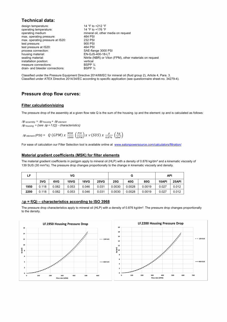
Technical data:
design temperature: 14 °F to +212 °F operating temperature: 14 °F to +176 °F operating medium mineral oil, other media on request max. operating pressure: 464 PSI max. operating pressure at IS20: 232 PSI test pressure: 900 PSI test pressure at IS20: 464 PSI process connection: SAE-flange 3000 PSI housing material: EN-GJS-400-18-LT sealing material: Nitrile (NBR) or Viton (FPM), other materials on request installation position: vertical measure connections: BSPP ¼ drain- and bleeder connections: BSPP ½
Classified under the Pressure Equipment Directive 2014/68/EC for mineral oil (fluid group 2), Article 4, Para. 3. Classified under ATEX Directive 2014/34/EC according to specific application (see questionnaire sheet-no. 34279-4).
Pressure drop flow curves:
Filter calculation/sizing
The pressure drop of the assembly at a given flow rate Q is the sum of the housing ∆p and the element ∆p and is calculated as follows:
p assembly = p housing + p element p housing = (see p = f (Q) - characteristics)
p element (PSI) = .
³
For ease of calculation our Filter Selection tool is available online at www.eatonpowersource.com/calculators/filtration/
Material gradient coefficients (MSK) for filter elements
The material gradient coefficients in psi/gpm apply to mineral oil (HLP) with a density of 0.876 kg/dm³ and a kinematic viscosity of 139 SUS (30 mm²/s). The pressure drop changes proportionally to the change in kinematic viscosity and density.
LF VG G API
3VG 6VG 10VG 16VG 25VG 25G 40G 80G 10API 25API
1950 0.118 0.082 0.053 0.046 0.031 0.0030 0.0028 0.0019 0.027 0.012
2200 0.118 0.082 0.053 0.046 0.031 0.0030 0.0028 0.0019 0.027 0.012
∆p = f(Q) – characteristics according to ISO 3968
The pressure drop characteristics apply to mineral oil (HLP) with a density of 0.876 kg/dm³. The pressure drop changes proportionally to the density.

Symbols: without indicator with electric
indicator AE 30 and AE 40
with visual-electric indicator
AE 50 and AE 62
with visual-electric indicator
AE 70 and AE 80
with visual indicator
OP
with visual-electric indicator
OE
with electronic clogging sensor
VS5 filter without internal valve
filter with by-pass valve
Spare parts: item qty. designation dimension article-no.
1 2 filter element 01NR.1000… 2 4 O-ring 90 x 4 306941 (NBR) 307031 (FPM) 3 2 O-ring 185 x 4 305593 (NBR) 306309 (FPM) 4 1 O-ring LF 1950 85,32 x 3,53 305590 (NBR) 306308 (FPM) 1 O-ring LF 2200 136,12 x 3,53 320162 (NBR) 320163 (FPM)
5 4 screw plug ½ BSPP 304678 6 2 screw plug ¼ BSPP 305003 7 1 connecting pipe 21689-4 313233 8 1 clogging indicator, visual OP see sheet-no. 1628 9 1 clogging indicator, visual-electric OE see sheet-no. 1628
10 1 clogging indicator, visual-electric AE see sheet-no. 1609 11 1 clogging sensor, electronic VS5 see sheet-no. 1641 12 2 O-ring 14 x 2 304342 (NBR) 304722 (FPM) 13 2 screw plug ¼ BSPP 305003
item 13 execution only without clogging indicator or clogging sensor
Test methods: Filter elements are tested according to the following ISO standards:
ISO 2941 Verification of collapse/burst resistance ISO 2942 Verification of fabrication integrity ISO 2943 Verification of material compatibility with fluids ISO 3723 Method for end load test ISO 3724 Verification of flow fatigue characteristics ISO 3968 Evaluation of pressure drop versus flow characteristics ISO 16889 Multi-pass method for evaluating filtration performance
North America 44 Apple Street Tinton Falls, NJ 07724
Toll Free: 800 656-3344 (North America only)
Tel: +1 732 212-4700 Europe/Africa/Middle East Auf der Heide 2 53947 Nettersheim, Germany
Tel: +49 2486 809-0
Friedensstraße 41 68804 Altlußheim, Germany
Tel: +49 6205 2094-0
An den Nahewiesen 24 55450 Langenlonsheim, Germany
Tel: +49 6704 204-0
China No. 3, Lane 280, Linhong Road Changning District, 200335 Shanghai, P.R. China
Tel: +86 21 5200-0099 Singapore 4 Loyang Lane #04-01/02 Singapore 508914
Tel: +65 6825-1668 Brazil Av. Julia Gaioli, 474 – Bonsucesso 07251-500 – Guarulhos, Brazil
Tel: +55 11 2465-8822
For more information, please email us at [email protected]
or visit www.eaton.com/filtration
© 2015 Eaton. All rights reserved. All trademarks and registered trademarks are the property of their respective owners. All information and recommendations appearing in this brochure concerning the use of products described herein are based on tests believed to be reliable. However, it is the user’s responsibility to determine the suitability for his own use of such products. Since the actual use by others is beyond our control, no guarantee, expressed or implied, is made by Eaton as to the effects of such use or the results to be obtained. Eaton assumes no liability arising out of the use by others of such products. Nor is the information herein to be construed as absolutely complete, since additional information may be necessary or desirable when particular or exceptional conditions or circumstances exist or because of applicable laws or government regulations.

Series LF 2005-4005
464 PSI
1) Connect the stand grounding tab to a suitable earth ground point.
PRESSURE FILTER
Sheet No. 1128 B
EDV 09/15
Weight LF 2005: approx. 392 lbs. Weight LF 3005: approx. 545 lbs. Weight LF 4005: approx. 626 lbs. Dimensions: inches Designs and performance values are subject to change.

Pressure Filter
Series LF 2005-4005
464 PSI
Description: In-line filter series LF 2005-4005 have a working pressure up to 464 PSI. Pressure peaks can be absorbed with a sufficient safety margin. The LF filter is mounted in-line. It can be used as suction filter, pressure filter and return-line filter.
The filter element consists of star-shaped, pleated filter material which is supported on the inside by a perforated core tube and is bonded to the end caps with a high-quality adhesive. The flow direction is from outside to inside.
For cleaning the mesh element or changing the glass fiber element, remove the cover and take out the element. The mesh elements are not guaranteed to maintain 100% performance after cleaning.
For filtration finer than 40 μm, use the disposable elements made of microglass. Filter elements as fine as 5 μm(c) are available; finer filter elements upon request.
Eaton-filter elements are known for a high intrinsic stability and an excellent filtration capability, a high dirt-retaining capacity and a long service life.
Eaton filter elements are suitable for all petroleum based fluids, HW-emulsions, most synthetic hydraulic fluids and lubrication oils.
The by-pass valve is integrated into the filter head. After reaching the by-pass pressure setting, the by-pass valve will send unfiltered partial flow around the filter. Ship classifications available upon request.
1. Type index:
1.1. Complete filter: (ordering example)
LF. 2005. 10VG. 10. E. P. -. FS. C. -. AE1 2 3 4 5 6 7 8 9 10 11
1 series: LF = In-line filter
2 nominal size: 2005, 3005, 4005
3 filter-material and filter-fineness: 80G, 40G, 25G, 10G stainless steel wire mesh 25VG, 16VG, 10VG, 6VG, 3VG microglass 25API, 10API microglass according to API
4 filter element collapse rating: 10 = p 145 PSI
5 filter element design: E = without by-pass valve S = with by-pass valve p 29 PSI
6 sealing material: P = Nitrile (NBR) V = Viton (FPM)
7 filter element specification: (see catalog) - = standard VA = stainless steel IS06 = for HFC applications, see sheet-no. 31601
8 process connection: FS = SAE-flange 3000 PSI
9 process connection size: C = 5“
10 filter housing specification: (see catalog) - = standard IS06 = for HFC applications, see sheet-no. 31605 IS20 = ASME VIII Div.1 with ASME equivalent material,
see sheet-no. 55217 (operating pressure max. 232 PSI
11 internal valve: - = without S = with by-pass valve p 29 PSI S1 = with by-pass valve p 51 PSI
12 clogging indicator or clogging sensor: - = without AE = visual-electric, see sheet-no. 1609 OP = visual, see sheet-no. 1628 OE = visual-electric, see sheet-no. 1628 VS5 = electronic, see sheet-no. 1641
1.2. Filter element: (ordering example)
01E. 2001. 10VG. 10. E. P. - 1 2 3 4 5 6 7
1 series: 01E. = filter element according to company standard
2 nominal size: 2001
3 - 7 see type index-complete filter
Accessories:- gauge port- and bleeder connection, see sheet-no. 1650 - drain- and bleeder connection, see sheet-no. 1651 - SAE-counter flange, see sheet-no. 1652
.

Technical data:
design temperature: 14 °F to +212 °F operating temperature: 14 °F to +176 °F operating medium mineral oil, other media on request max. operating pressure: 464 PSI max. operating pressure at IS20: 232 PSI test pressure: 900 PSI test pressure at IS20: 464 PSI process connection: SAE-flange 3000 PSI housing material: EN-GJS-400-18-LT sealing material: Nitrile (NBR) or Viton (FPM), other materials on request installation position: vertical measure connections: BSPP ¼ drain- and bleeder connections: BSPP ½ volume tank LF 2005: 6 Gal. LF 3005: 8 Gal. LF 4005. 10 Gal.
Classified under the Pressure Equipment Directive 2014/68/EC for mineral oil (fluid group 2), Article 4, Para. 3. Classified under ATEX Directive 2014/34/EC according to specific application (see questionnaire sheet-no. 34279-4).
Pressure drop flow curves:
Filter calculation/sizing
The pressure drop of the assembly at a given flow rate Q is the sum of the housing ∆p and the element ∆p and is calculated as follows:
p assembly = p housing + p element p housing = (see p = f (Q) - characteristics)
p element (PSI) = .
³
For ease of calculation our Filter Selection tool is available online at www.eatonpowersource.com/calculators/filtration/
Material gradient coefficients (MSK) for filter elements
The material gradient coefficients in psi/gpm apply to mineral oil (HLP) with a density of 0.876 kg/dm³ and a kinematic viscosity of 139 SUS (30 mm²/s). The pressure drop changes proportionally to the change in kinematic viscosity and density.
LF VG G API
3VG 6VG 10VG 16VG 25VG 25G 40G 80G 10API 25API
2005 0.177 0.123 0.079 0.068 0.047 0.0059 0.0055 0.0038 0.040 0.018
3005 0.118 0.082 0.052 0.046 0.031 0.0040 0.0037 0.0025 0.027 0.012
4005 0.088 0.061 0.039 0.034 0.023 0.0030 0.0028 0.0019 0.020 0.009
∆p = f(Q) – characteristics according to ISO 3968
The pressure drop characteristics apply to mineral oil (HLP) with a density of 0.876 kg/dm³. The pressure drop changes proportionally to the density.

Symbols: without indicator with electric
indicator AE 30 and AE 40
with visual-electric indicator
AE 50 and AE 62
with visual-electric indicator
AE 70 and AE 80
with visual indicator
OP
with visual-electric indicator
OE
with electronic clogging sensor
VS5 filter without internal valve
filter with by-pass valve
Spare parts: item qty. designation dimension and
article-no. dimension and
article-no. dimension and
article-no. LF 2005 LF 3005 LF 4005
1 1 filter element 01E.2001… 01E.3001… 01E.4001…
2 1 O-ring 135 x 10 306016 (NBR) 307045 (FPM)
3 1 O-ring 125 x 10 304388 (NBR) 306006 (FPM)
4 1 O-ring (LF 2005) 240 x 5 307592 (NBR) 2 O-ring (LF 3005/4005) 328793 (FPM)
5 1 O-ring 136,12 x 3,53 320162 (NBR) 320163 (FPM)
6 4 screw plug (LF 2005) BSPP ½ 304678 5 screw plug (LF 3005/4005)
7 2 screw plug BSPP ¼ 305003
8 1 clogging indicator visual-electric OE see seet-no. 1628
9 1 clogging indicator visual OP see seet-no. 1628
10 1 clogging indicator visual-electric AE see seet-no. 1609
11 1 clogging sensor electronic VS5 see seet-no. 1641
12 2 O-ring 14 x 2 304342 (NBR) 304722 (FPM)
13 2 screw plug BSPP ¼ 305003
item 13 execution only without clogging indicator or clogging sensor
Test methods: Filter elements are tested according to the following ISO standards:
ISO 2941 Verification of collapse/burst resistance ISO 2942 Verification of fabrication integrity ISO 2943 Verification of material compatibility with fluids ISO 3723 Method for end load test ISO 3724 Verification of flow fatigue characteristics ISO 3968 Evaluation of pressure drop versus flow characteristics ISO 16889 Multi-pass method for evaluating filtration performance
North America 44 Apple Street Tinton Falls, NJ 07724
Toll Free: 800 656-3344 (North America only)
Tel: +1 732 212-4700 Europe/Africa/Middle East Auf der Heide 2 53947 Nettersheim, Germany
Tel: +49 2486 809-0
Friedensstraße 41 68804 Altlußheim, Germany
Tel: +49 6205 2094-0
An den Nahewiesen 24 55450 Langenlonsheim, Germany
Tel: +49 6704 204-0
China No. 3, Lane 280, Linhong Road Changning District, 200335 Shanghai, P.R. China
Tel: +86 21 5200-0099 Singapore 4 Loyang Lane #04-01/02 Singapore 508914
Tel: +65 6825-1668 Brazil Av. Julia Gaioli, 474 – Bonsucesso 07251-500 – Guarulhos, Brazil
Tel: +55 11 2465-8822
For more information, please email us at [email protected]
or visit www.eaton.com/filtration
© 2015 Eaton. All rights reserved. All trademarks and registered trademarks are the property of their respective owners. All information and recommendations appearing in this brochure concerning the use of products described herein are based on tests believed to be reliable. However, it is the user’s responsibility to determine the suitability for his own use of such products. Since the actual use by others is beyond our control, no guarantee, expressed or implied, is made by Eaton as to the effects of such use or the results to be obtained. Eaton assumes no liability arising out of the use by others of such products. Nor is the information herein to be construed as absolutely complete, since additional information may be necessary or desirable when particular or exceptional conditions or circumstances exist or because of applicable laws or government regulations.

Series DTEF 70
145 PSI
RETURN LINE FILTER, change over
Sheet No. 1021 G
EDV 09/15
Weight: approx. 8.0 lbs.
Dimensions: inches Designs and performance values are subject to change.
Position I: left filter-side in operation Position II: right filter-side in operation

Return Line Filter
Series DTEF 70
145 PSI
Description:
Return-line filter series DTEF 70 have a working pressure up to 145 PSI.
The DTEF-filters are directly mounted to the reservoir and connected to the return-line.
A three way changeover valve which is integrated in the middle of the housing makes it possible to switch from the dirty filter-side to the clean filter-side without interrupting operation. These filters can be installed as suction filters.
The filter element consists of star-shaped, pleated filter material, which is supported on the inside by a perforated core tube and is bonded to the end caps with a high-quality adhesive. The flow direction is from outside to inside.
Eaton filter elements are known for a high intrinsic stability and an excellent filtration capability, a high dirt-retaining capacity and a long service life.
For filtration finer than 40 μm use the disposable elements made of microglass. Filter elements as fine as 5 μm(c) are available; finer filter elements on request.
Eaton filter elements can be used for petroleum-based fluids, HW emulsions, water glycols, most synthetic fluids and lubrication fluids. Consult factory for specific fluid applications.
When changing the filter element, a detachable connection between the filter head and the filter bowl prevents dirty oil from flowing into the tank.
1. Type index:
1.1. Complete filter: (ordering example)
DTEF. 70. 10VG. 16. S. P. -. G. 4. -. O. E11 2 3 4 5 6 7 8 9 10 11 12
1 series: DTEF = tank-mounted return-line-filter, change over
2 nominal size: 70
3 filter-material and filter-fineness: 80G, 40G, 25G stainless steel wire mesh 25VG, 16VG, 10VG, 6VG, 3VG microglass 10P paper
4 filter element collapse rating: 16 = p 232 PSI
5 filter element design: E = without by-pass valve S = with by-pass valve p 29 PSI
6 sealing material: P = Nitrile (NBR) V = Viton (FPM)
7 filter element specification: (see catalog) - = standard VA = stainless steel IS06 = for HFC application, see sheet-no. 31601
8 process connection: G = thread connection
9 process connection size: 4 = BSPP ¾
10 filter housing specification: (see catalog) - = standard IS06 = for HFC application, see sheet-no. 31605
11 clogging indicator at M1: - = without O = visual, see sheet-no. 1616 E1 = pressure switch, see sheet-no. 1616 E2 = pressure switch, see sheet-no. 1616 E5 = pressure switch, see sheet-no. 1616
12 clogging indicator at M2: possible indicators see position 11 of the type index
To add an indicator to your filter, use the corresponding indicator data sheet to find the indicator details and add them to the filter assembly model code.
1.2. Filter element: (ordering example)
01E. 70. 10VG. 16. S. P. - 1 2 3 4 5 6 7
1 series: 01E. = filter element according to company standard
2 nominal size: 70
3 - 7 see type index-complete filter

Technical data:
design temperature: 14 °F to +212 °F operating temperature: 14 °F to +176 °F operating medium mineral oil, other media on request max. operating pressure: 145 PSI opening pressure by-pass valve: 29 PSI process connection: thread connection housing material standard: Al-casting, glass fibre reinforced polyamide sealing material: Nitrile (NBR) or Viton (FPM), other materials on request installation position: vertical volume tank: 2x .08 Gal.
Classified under the Pressure Equipment Directive 2014/68/EC for mineral oil (fluid group 2), Article 4, Para. 3. Classified under ATEX Directive 2014/34/EC according to specific application (see questionnaire sheet-no. 34279-4).
Pressure drop flow curves:
Filter calculation/sizing
The pressure drop of the assembly at a given flow rate Q is the sum of the housing ∆p and the element ∆p and is calculated as follows:
p assembly = p housing + p element p housing = (see p = f (Q) - characteristics)
p element (PSI) = .
³
For ease of calculation our Filter Selection tool is available online at www.eatonpowersource.com/calculators/filtration/
Material gradient coefficients (MSK) for filter elements
The material gradient coefficients in psi/gpm apply to mineral oil (HLP) with a density of 0.876 kg/dm³ and a kinematic viscosity of 139 SUS (30 mm²/s). The pressure drop changes proportionally to the change in kinematic viscosity and density.
DTEF VG G P
3VG 6VG 10VG 16VG 25VG 25G 40G 80G 10P
70 3.535 2.454 1.571 1.368 0.935 0.1196 0.1117 0.0765 0.797
∆p = f(Q) – characteristics according to ISO 3968
The pressure drop characteristics apply to mineral oil (HLP) with a density of 0.876 kg/dm³. The pressure drop changes proportionally to the density.
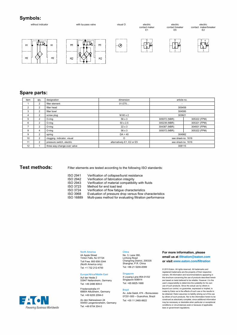
Symbols: without indicator with by-pass valve visual O electric
contact maker E1
electric contact breaker
E5
electric contact maker/breaker
E2
Spare parts: item qty. designation dimension article-no.
1 2 filter element 01.E70… -
2 2 filter head 305459
3 2 filter bowl 304595
4 2 screw plug M 60 x 2 303621
5 2 O-ring 56 x 3 305072 (NBR) 305322 (FPM)
6 2 O-ring 50 x 2,5 305239 (NBR) 305321 (FPM)
7 2 O-ring 22 x 3 304387 (NBR) 304931 (FPM)
8 4 O-ring 56 x 3 305072 (NBR) 305322 (FPM)
9 2 spring DA = 40 304982
10 2 clogging indicator, visual O see sheet-no. 1616
11 2 pressure switch, electric alternatively E1, E2 or E5 see sheet-no. 1616
12 1 three-way-change-over valve 308115
Test methods: Filter elements are tested according to the following ISO standards:
ISO 2941 Verification of collapse/burst resistance ISO 2942 Verification of fabrication integrity ISO 2943 Verification of material compatibility with fluids ISO 3723 Method for end load test ISO 3724 Verification of flow fatigue characteristics ISO 3968 Evaluation of pressure drop versus flow characteristics ISO 16889 Multi-pass method for evaluating filtration performance
North America 44 Apple Street Tinton Falls, NJ 07724
Toll Free: 800 656-3344 (North America only)
Tel: +1 732 212-4700 Europe/Africa/Middle East Auf der Heide 2 53947 Nettersheim, Germany
Tel: +49 2486 809-0
Friedensstraße 41 68804 Altlußheim, Germany
Tel: +49 6205 2094-0
An den Nahewiesen 24 55450 Langenlonsheim, Germany
Tel: +49 6704 204-0
China No. 3, Lane 280, Linhong Road Changning District, 200335 Shanghai, P.R. China
Tel: +86 21 5200-0099 Singapore 4 Loyang Lane #04-01/02 Singapore 508914
Tel: +65 6825-1668 Brazil Av. Julia Gaioli, 474 – Bonsucesso 07251-500 – Guarulhos, Brazil
Tel: +55 11 2465-8822
For more information, please email us at [email protected]
or visit www.eaton.com/filtration
© 2015 Eaton. All rights reserved. All trademarks and registered trademarks are the property of their respective owners. All information and recommendations appearing in this brochure concerning the use of products described herein are based on tests believed to be reliable. However, it is the user’s responsibility to determine the suitability for his own use of such products. Since the actual use by others is beyond our control, no guarantee, expressed or implied, is made by Eaton as to the effects of such use or the results to be obtained. Eaton assumes no liability arising out of the use by others of such products. Nor is the information herein to be construed as absolutely complete, since additional information may be necessary or desirable when particular or exceptional conditions or circumstances exist or because of applicable laws or government regulations.

Series DTEF 120
145 PSI
RETURN LINE FILTER, change over
Sheet No. 1022 H
EDV 09/15
Weight: approx. 13 lbs.
Dimensions: inches Designs and performance values are subject to change.
Position I: left filter-side in operation Position II: right filter-side in operation
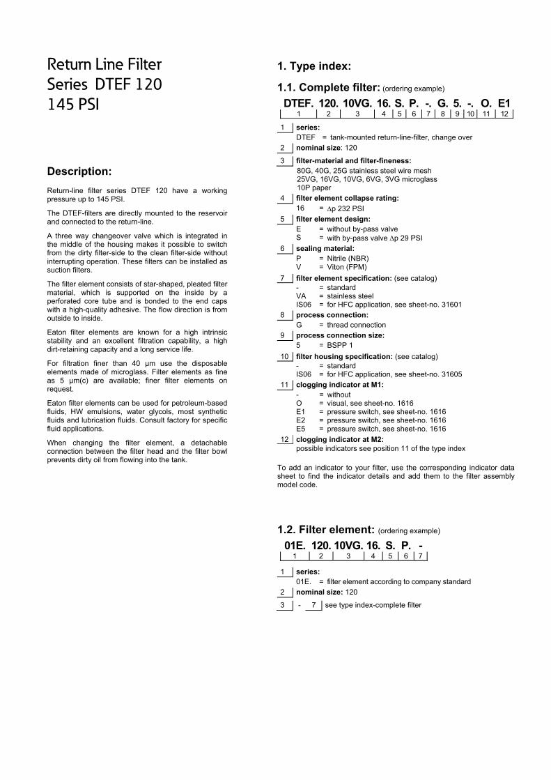
Return Line Filter
Series DTEF 120
145 PSI
Description:
Return-line filter series DTEF 120 have a working pressure up to 145 PSI.
The DTEF-filters are directly mounted to the reservoir and connected to the return-line.
A three way changeover valve which is integrated in the middle of the housing makes it possible to switch from the dirty filter-side to the clean filter-side without interrupting operation. These filters can be installed as suction filters.
The filter element consists of star-shaped, pleated filter material, which is supported on the inside by a perforated core tube and is bonded to the end caps with a high-quality adhesive. The flow direction is from outside to inside.
Eaton filter elements are known for a high intrinsic stability and an excellent filtration capability, a high dirt-retaining capacity and a long service life.
For filtration finer than 40 μm use the disposable elements made of microglass. Filter elements as fine as 5 μm(c) are available; finer filter elements on request.
Eaton filter elements can be used for petroleum-based fluids, HW emulsions, water glycols, most synthetic fluids and lubrication fluids. Consult factory for specific fluid applications.
When changing the filter element, a detachable connection between the filter head and the filter bowl prevents dirty oil from flowing into the tank.
1. Type index:
1.1. Complete filter: (ordering example)
DTEF. 120. 10VG. 16. S. P. -. G. 5. -. O. E11 2 3 4 5 6 7 8 9 10 11 12
1 series: DTEF = tank-mounted return-line-filter, change over
2 nominal size: 120
3 filter-material and filter-fineness: 80G, 40G, 25G stainless steel wire mesh 25VG, 16VG, 10VG, 6VG, 3VG microglass 10P paper
4 filter element collapse rating: 16 = p 232 PSI
5 filter element design: E = without by-pass valve S = with by-pass valve p 29 PSI
6 sealing material: P = Nitrile (NBR) V = Viton (FPM)
7 filter element specification: (see catalog) - = standard VA = stainless steel IS06 = for HFC application, see sheet-no. 31601
8 process connection: G = thread connection
9 process connection size: 5 = BSPP 1
10 filter housing specification: (see catalog) - = standard IS06 = for HFC application, see sheet-no. 31605
11 clogging indicator at M1: - = without O = visual, see sheet-no. 1616 E1 = pressure switch, see sheet-no. 1616 E2 = pressure switch, see sheet-no. 1616 E5 = pressure switch, see sheet-no. 1616
12 clogging indicator at M2: possible indicators see position 11 of the type index
To add an indicator to your filter, use the corresponding indicator data sheet to find the indicator details and add them to the filter assembly model code.
1.2. Filter element: (ordering example)
01E. 120. 10VG. 16. S. P. - 1 2 3 4 5 6 7
1 series: 01E. = filter element according to company standard
2 nominal size: 120
3 - 7 see type index-complete filter

Technical data:
design temperature: 14 °F to +212 °F operating temperature: 14 °F to +176 °F operating medium mineral oil, other media on request max. operating pressure: 145 PSI opening pressure by-pass valve: 29 PSI process connection: thread connection housing material standard: Al-casting, glass fiber reinforced polyamide sealing material: Nitrile (NBR) or Viton (FPM), other materials on request installation position: vertical volume tank: 2x .16 Gal.
Classified under the Pressure Equipment Directive 2014/68/EC for mineral oil (fluid group 2), Article 4, Para. 3. Classified under ATEX Directive 2014/34/EC according to specific application (see questionnaire sheet-no. 34279-4).
Pressure drop flow curves:
Filter calculation/sizing
The pressure drop of the assembly at a given flow rate Q is the sum of the housing ∆p and the element ∆p and is calculated as follows:
p assembly = p housing + p element p housing = (see p = f (Q) - characteristics)
p element (PSI) = .
³
For ease of calculation our Filter Selection tool is available online at www.eatonpowersource.com/calculators/filtration/
Material gradient coefficients (MSK) for filter elements
The material gradient coefficients in psi/gpm apply to mineral oil (HLP) with a density of 0.876 kg/dm³ and a kinematic viscosity of 139 SUS (30 mm²/s). The pressure drop changes proportionally to the change in kinematic viscosity and density.
DTEF VG G P
3VG 6VG 10VG 16VG 25VG 25G 40G 80G 10P
120 3.162 2.195 1.405 1.224 0.836 0.1144 0.1068 0.0731 0.690
∆p = f(Q) – characteristics according to ISO 3968
The pressure drop characteristics apply to mineral oil (HLP) with a density of 0.876 kg/dm³. The pressure drop changes proportionally to the density.

Symbols: without indicator with by-pass valve visual O electric
contact maker E1
electric contact breaker
E5
electric contact maker/breaker
E2
Spare parts: item qty. designation dimension article-no.
1 2 filter element 01.E120…
2 2 filter head 305467
3 2 filter bowl 303041
4 2 screw plug M 60 x 2 302069
5 2 O-ring 75 x 3 302215 (NBR) 304729 (FPM)
6 2 O-ring 68 x 4 303037 (NBR) 313046 (FPM)
7 2 O-ring 24 x 3 303038 (NBR) 304397 (FPM)
8 4 O-ring 86 x 3 305470 (NBR) 313047 (FPM)
9 2 spring DA = 52 302144
10 2 clogging indicator, visual O see sheet-no. 1616
11 2 pressure switch, electric alternatively E1, E2 or E5 see sheet-no. 1616
12 1 three-way-change-over valve 308123
Test methods: Filter elements are tested according to the following ISO standards:
ISO 2941 Verification of collapse/burst resistance ISO 2942 Verification of fabrication integrity ISO 2943 Verification of material compatibility with fluids ISO 3723 Method for end load test ISO 3724 Verification of flow fatigue characteristics ISO 3968 Evaluation of pressure drop versus flow characteristics ISO 16889 Multi-pass method for evaluating filtration performance
North America 44 Apple Street Tinton Falls, NJ 07724
Toll Free: 800 656-3344 (North America only)
Tel: +1 732 212-4700 Europe/Africa/Middle East Auf der Heide 2 53947 Nettersheim, Germany
Tel: +49 2486 809-0
Friedensstraße 41 68804 Altlußheim, Germany
Tel: +49 6205 2094-0
An den Nahewiesen 24 55450 Langenlonsheim, Germany
Tel: +49 6704 204-0
China No. 3, Lane 280, Linhong Road Changning District, 200335 Shanghai, P.R. China
Tel: +86 21 5200-0099 Singapore 4 Loyang Lane #04-01/02 Singapore 508914
Tel: +65 6825-1668 Brazil Av. Julia Gaioli, 474 – Bonsucesso 07251-500 – Guarulhos, Brazil
Tel: +55 11 2465-8822
For more information, please email us at [email protected] or visit www.eaton.com/filtration
© 2015 Eaton. All rights reserved. All trademarks and registered trademarks are the property of their respective owners. All information and recommendations appearing in this brochure concerning the use of products described herein are based on tests believed to be reliable. However, it is the user’s responsibility to determine the suitability for his own use of such products. Since the actual use by others is beyond our control, no guarantee, expressed or implied, is made by Eaton as to the effects of such use or the results to be obtained. Eaton assumes no liability arising out of the use by others of such products. Nor is the information herein to be construed as absolutely complete, since additional information may be necessary or desirable when particular or exceptional conditions or circumstances exist or because of applicable laws or government regulations.
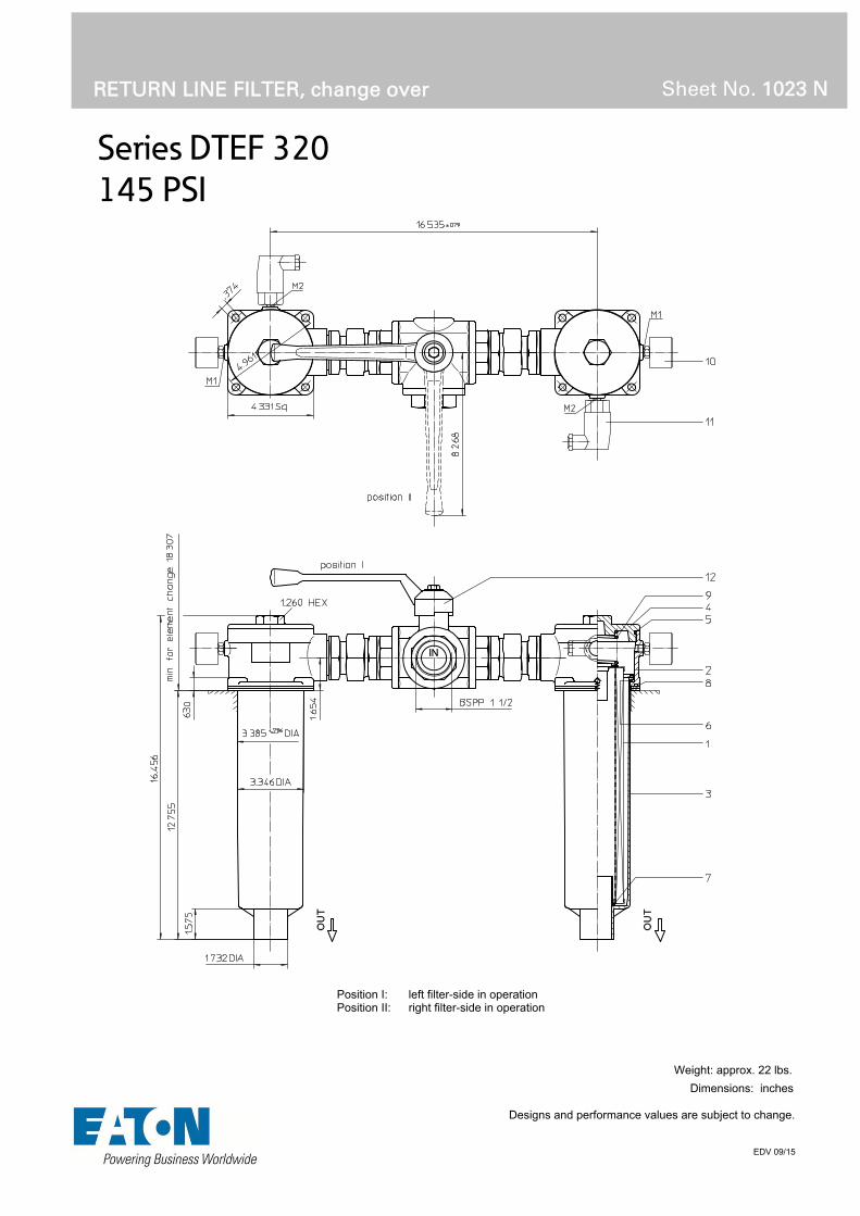
Series DTEF 320
145 PSI
RETURN LINE FILTER, change over
Sheet No. 1023 N
EDV 09/15
Weight: approx. 22 lbs.
Dimensions: inches Designs and performance values are subject to change.
Position I: left filter-side in operation Position II: right filter-side in operation

Return Line Filter
Series DTEF 320
145 PSI
Description:
Return-line filter series DTEF 320 have a working pressure up to 145 PSI.
The DTEF-filters are directly mounted to the reservoir and connected to the return-line.
A three way changeover valve which is integrated in the middle of the housing makes it possible to switch from the dirty filter-side to the clean filter-side without interrupting operation. These filters can be installed as suction filters.
The filter element consists of star-shaped, pleated filter material, which is supported on the inside by a perforated core tube and is bonded to the end caps with a high-quality adhesive. The flow direction is from outside to inside.
Eaton filter elements are known for a high intrinsic stability and an excellent filtration capability, a high dirt-retaining capacity and a long service life.
For filtration finer than 40 μm use the disposable elements made of microglass. Filter elements as fine as 5 μm(c) are available; finer filter elements on request.
Eaton filter elements can be used for petroleum-based fluids, HW emulsions, water glycols, most synthetic fluids and lubrication fluids. Consult factory for specific fluid applications.
When changing the filter element, a detachable connection between the filter head and the filter bowl prevents dirty oil from flowing into the tank.
1. Type index:
1.1. Complete filter: (ordering example)
DTEF. 320. 10VG. 16. S. P. -. G. 7. -. O. E11 2 3 4 5 6 7 8 9 10 11 12
1 series: DTEF = tank-mounted return-line-filter, change over
2 nominal size: 320
3 filter-material and filter-fineness: 80G, 40G, 25G stainless steel wire mesh 25VG, 16VG, 10VG, 6VG, 3VG microglass 10P paper
4 filter element collapse rating: 16 = p 232 PSI
5 filter element design: E = without by-pass valve S = with by-pass valve p 29 PSI
6 sealing material: P = Nitrile (NBR) V = Viton (FPM)
7 filter element specification: (see catalog) - = standard VA = stainless steel IS06 = for HFC application, see sheet-no. 31601
8 process connection: G = thread connection
9 process connection size: 7 = BSPP 1 ½
10 filter housing specification: (see catalog) - = standard IS06 = for HFC application, see sheet-no. 31605
11 clogging indicator at M1: - = without O = visual, see sheet-no. 1616 E1 = pressure switch, see sheet-no. 1616 E2 = pressure switch, see sheet-no. 1616 E5 = pressure switch, see sheet-no. 1616
12 clogging indicator at M2: possible indicators see position 11 of the type index
To add an indicator to your filter, use the corresponding indicator data sheet to find the indicator details and add them to the filter assembly model code.
1.2. Filter element: (ordering example)
01E. 320. 10VG. 16. S. P. - 1 2 3 4 5 6 7
1 series: 01E. = filter element according to company standard
2 nominal size: 320
3 - 7 see type index-complete filter

Technical data:
design temperature: 14 °F to +212 °F operating temperature: 14 °F to +176 °F operating medium mineral oil, other media on request max. operating pressure: 145 PSI opening pressure by-pass valve: 29 PSI process connection: thread connection housing material standard: Al-casting, glass fibre reinforced polyamide sealing material: Nitrile (NBR) or Viton (FPM), other materials on request installation position: vertical volume tank: 2x .48 Gal.
Classified under the Pressure Equipment Directive 2014/68/EC for mineral oil (fluid group 2), Article 4, Para. 3. Classified under ATEX Directive 2014/34/EC according to specific application (see questionnaire sheet-no. 34279-4).
Pressure drop flow curves:
Filter calculation/sizing
The pressure drop of the assembly at a given flow rate Q is the sum of the housing ∆p and the element ∆p and is calculated as follows:
p assembly = p housing + p element p housing = (see p = f (Q) - characteristics)
p element (PSI) = .
³
For ease of calculation our Filter Selection tool is available online at www.eatonpowersource.com/calculators/filtration/
Material gradient coefficients (MSK) for filter elements
The material gradient coefficients in psi/gpm apply to mineral oil (HLP) with a density of 0.876 kg/dm³ and a kinematic viscosity of 139 SUS (30 mm²/s). The pressure drop changes proportionally to the change in kinematic viscosity and density.
DTEF VG G P
3VG 6VG 10VG 16VG 25VG 25G 40G 80G 10P
320 1.148 0.797 0.510 0.444 0.304 0.0337 0.0314 0.0215 0.253
∆p = f(Q) – characteristics according to ISO 3968
The pressure drop characteristics apply to mineral oil (HLP) with a density of 0.876 kg/dm³. The pressure drop changes proportionally to the density.

Symbols: without indicator with by-pass valve visual O electric
contact maker E1
electric contact breaker
E5
electric contact maker/breaker
E2
Spare parts: item qty. designation dimension article-no.
1 2 filter element 01.E320…
2 2 filter head 305475
3 2 filter bowl 302145
4 2 screw plug M 100 x 2 302338
5 2 O-ring 96 x 3 305292 (NBR) 305297 (FPM)
6 2 O-ring 82 x 3 305191 (NBR) 305298 (FPM)
7 2 O-ring 40 x 3 304389 (NBR) 304391 (FPM)
8 4 gasket 110 x 110 x 3 304456 (NBR) 314138 (FPM)
9 2 spring DA = 52 305053
10 2 clogging indicator, visual O see sheet-no. 1616
11 2 pressure switch, electric alternatively E1, E2 or E5 see sheet-no. 1616
12 1 three-way-change-over valve 308128
Test methods: Filter elements are tested according to the following ISO standards:
ISO 2941 Verification of collapse/burst resistance ISO 2942 Verification of fabrication integrity ISO 2943 Verification of material compatibility with fluids ISO 3723 Method for end load test ISO 3724 Verification of flow fatigue characteristics ISO 3968 Evaluation of pressure drop versus flow characteristics ISO 16889 Multi-pass method for evaluating filtration performance
North America 44 Apple Street Tinton Falls, NJ 07724
Toll Free: 800 656-3344 (North America only)
Tel: +1 732 212-4700 Europe/Africa/Middle East Auf der Heide 2 53947 Nettersheim, Germany
Tel: +49 2486 809-0
Friedensstraße 41 68804 Altlußheim, Germany
Tel: +49 6205 2094-0
An den Nahewiesen 24 55450 Langenlonsheim, Germany
Tel: +49 6704 204-0
China No. 3, Lane 280, Linhong Road Changning District, 200335 Shanghai, P.R. China
Tel: +86 21 5200-0099 Singapore 4 Loyang Lane #04-01/02 Singapore 508914
Tel: +65 6825-1668 Brazil Av. Julia Gaioli, 474 – Bonsucesso 07251-500 – Guarulhos, Brazil
Tel: +55 11 2465-8822
For more information, please email us at [email protected]
or visit www.eaton.com/filtration
© 2015 Eaton. All rights reserved. All trademarks and registered trademarks are the property of their respective owners. All information and recommendations appearing in this brochure concerning the use of products described herein are based on tests believed to be reliable. However, it is the user’s responsibility to determine the suitability for his own use of such products. Since the actual use by others is beyond our control, no guarantee, expressed or implied, is made by Eaton as to the effects of such use or the results to be obtained. Eaton assumes no liability arising out of the use by others of such products. Nor is the information herein to be construed as absolutely complete, since additional information may be necessary or desirable when particular or exceptional conditions or circumstances exist or because of applicable laws or government regulations.

Series DTEF 426
145 PSI
RETURN LINE FILTER, change over
Sheet No. 1035 F
EDV 09/15
Weight: approx. 27.5 lbs.
Dimensions: inches Designs and performance values are subject to change.
Position I: left filter-side in operation Position II: right filter-side in operation

Return Line Filter
Series DTEF 426
145 PSI
Description:
Return-line filter series DTEF 426 have a working pressure up to 145 PSI.
The DTEF-filters are directly mounted to the reservoir and connected to the return-line.
A three way changeover valve which is integrated in the middle of the housing makes it possible to switch from the dirty filter-side to the clean filter-side without interrupting operation. These filters can be installed as suction filters.
The filter element consists of star-shaped, pleated filter material, which is supported on the inside by a perforated core tube and is bonded to the end caps with a high-quality adhesive. The flow direction is from outside to inside.
Eaton filter elements are known for a high intrinsic stability and an excellent filtration capability, a high dirt-retaining capacity and a long service life.
For filtration finer than 40 μm use the disposable elements made of microglass. Filter elements as fine as 5 μm(c) are available; finer filter elements on request.
Eaton filter elements can be used for petroleum-based fluids, HW emulsions, water glycols, most synthetic fluids and lubrication fluids. Consult factory for specific fluid applications.
When changing the filter element, a detachable connection between the filter head and the filter bowl prevents dirty oil from flowing into the tank.
1. Type index:
1.1. Complete filter: (ordering example)
DTEF. 426. 10VG. 16. S. P. -. G. 7. -. O. E1. -1 2 3 4 5 6 7 8 9 10 11 12 13
1 series: DTEF = tank-mounted return-line-filter, change over
2 nominal size: 426
3 filter-material and filter-fineness: 80G, 40G, 25G stainless steel wire mesh 25VG, 16VG, 10VG, 6VG, 3VG microglass 10P paper
4 filter element collapse rating: 16 = p 232 PSI
5 filter element design: E = without by-pass valve S = with by-pass valve p 29 PSI
6 sealing material: P = Nitrile (NBR) V = Viton (FPM)
7 filter element specification: (see catalog) - = standard VA = stainless steel IS06 = for HFC application, see sheet-no. 31601
8 process connection: G = thread connection
9 process connection size: 7 = BSPP 1 ½
10 filter housing specification: (see catalog) - = standard IS06 = for HFC application, see sheet-no. 31605
11 clogging indicator at M1: - = without O = visual, see sheet-no. 1616 E1 = pressure switch, see sheet-no. 1616 E2 = pressure switch, see sheet-no. 1616 E5 = pressure switch, see sheet-no. 1616
12 clogging indicator at M2: possible indicators see position 11 of the type index
13 clogging indicator at M3: possible indicators see position 11 of the type index
To add an indicator to your filter, use the corresponding indicator data sheet to find the indicator details and add them to the filter assembly model code.
1.2. Filter element: (ordering example)
01E. 425. 10VG. 16. S. P. - 1 2 3 4 5 6 7
1 series: 01E. = filter element according to company standard
2 nominal size: 425
3 - 7 see type index-complete filter

Technical data:
design temperature: 14 °F to +212 °F operating temperature: 14 °F to +176 °F operating medium mineral oil, other media on request max. operating pressure: 145 PSI opening pressure by-pass valve: 29 PSI process connection: thread connection housing material standard: Al-casting, glass fibre reinforced polyamide sealing material: Nitrile (NBR) or Viton (FPM), other materials on request installation position: vertical volume tank: 2x .70 Gal.
Classified under the Pressure Equipment Directive 2014/68/EC for mineral oil (fluid group 2), Article 4, Para. 3. Classified under ATEX Directive 2014/34/EC according to specific application (see questionnaire sheet-no. 34279-4).
Pressure drop flow curves:
Filter calculation/sizing
The pressure drop of the assembly at a given flow rate Q is the sum of the housing ∆p and the element ∆p and is calculated as follows:
p assembly = p housing + p element p housing = (see p = f (Q) - characteristics)
p element (PSI) = .
³
For ease of calculation our Filter Selection tool is available online at www.eatonpowersource.com/calculators/filtration/
Material gradient coefficients (MSK) for filter elements
The material gradient coefficients in psi/gpm apply to mineral oil (HLP) with a density of 0.876 kg/dm³ and a kinematic viscosity of 139 SUS (30 mm²/s). The pressure drop changes proportionally to the change in kinematic viscosity and density.
DTEF VG G P
3VG 6VG 10VG 16VG 25VG 25G 40G 80G 10P
426 0.849 0.589 0.377 0.328 0.224 0.0270 0.0252 0.0172 0.182
∆p = f(Q) – characteristics according to ISO 3968
The pressure drop characteristics apply to mineral oil (HLP) with a density of 0.876 kg/dm³. The pressure drop changes proportionally to the density.

Symbols: without indicator with by-pass valve visual O electric
contact maker E1
electric contact breaker
E5
electric contact maker/breaker
E2
Spare parts: item qty. designation dimension article-no.
1 2 filter element 01.E425…
2 2 filter head 313434
3 2 filter bowl 303732
4 2 screw plug M 120 x 3 313649
5 2 O-ring 128 x 3 304602 (NBR) 308140 (FPM)
6 2 O-ring 98 x 4 301914 (NBR) 304765 (FPM)
7 2 O-ring 44 x 6 302222 (NBR) 304384 (FPM)
8 4 O-ring 115 x 3 303963 (NBR) 307762 (FPM)
9 2 spring DA = 63,5 304983
10 2 clogging indicator. visual O see sheet-no. 1616
11 2 pressure switch, electric alternatively E1, E2 or E5 see sheet-no. 1616
12 1 three-way-change-over valve 308128
Test methods: Filter elements are tested according to the following ISO standards:
ISO 2941 Verification of collapse/burst resistance ISO 2942 Verification of fabrication integrity ISO 2943 Verification of material compatibility with fluids ISO 3723 Method for end load test ISO 3724 Verification of flow fatigue characteristics ISO 3968 Evaluation of pressure drop versus flow characteristics ISO 16889 Multi-pass method for evaluating filtration performance
North America 44 Apple Street Tinton Falls, NJ 07724
Toll Free: 800 656-3344 (North America only)
Tel: +1 732 212-4700 Europe/Africa/Middle East Auf der Heide 2 53947 Nettersheim, Germany
Tel: +49 2486 809-0
Friedensstraße 41 68804 Altlußheim, Germany
Tel: +49 6205 2094-0
An den Nahewiesen 24 55450 Langenlonsheim, Germany
Tel: +49 6704 204-0
China No. 3, Lane 280, Linhong Road Changning District, 200335 Shanghai, P.R. China
Tel: +86 21 5200-0099 Singapore 4 Loyang Lane #04-01/02 Singapore 508914
Tel: +65 6825-1668 Brazil Av. Julia Gaioli, 474 – Bonsucesso 07251-500 – Guarulhos, Brazil
Tel: +55 11 2465-8822
For more information, please email us at [email protected]
or visit www.eaton.com/filtration
© 2015 Eaton. All rights reserved. All trademarks and registered trademarks are the property of their respective owners. All information and recommendations appearing in this brochure concerning the use of products described herein are based on tests believed to be reliable. However, it is the user’s responsibility to determine the suitability for his own use of such products. Since the actual use by others is beyond our control, no guarantee, expressed or implied, is made by Eaton as to the effects of such use or the results to be obtained. Eaton assumes no liability arising out of the use by others of such products. Nor is the information herein to be construed as absolutely complete, since additional information may be necessary or desirable when particular or exceptional conditions or circumstances exist or because of applicable laws or government regulations.

Series DTEF 625
145 PSI
RETURN LINE FILTER, change over
Sheet No. 1074 D
EDV 09/15
Weight: approx. 33 lbs.
Dimensions: inches Designs and performance values are subject to change.
Position I: left filter-side in operation Position II: right filter-side in operation

Return Line Filter
Series DTEF 625
145 PSI
Description:
Return-line filter series DTEF 625 have a working pressure up to 145 PSI.
The DTEF-filters are directly mounted to the reservoir and connected to the return-line.
A rotary slide valve which is integrated in the middle of the housing makes it possible to switch from the dirty filter-side to the clean filter-side without interrupting operation. These filters can be installed as suction filters.
The filter element consists of star-shaped, pleated filter material, which is supported on the inside by a perforated core tube and is bonded to the end caps with a high-quality adhesive. The flow direction is from outside to inside.
Eaton filter elements are known for a high intrinsic stability and an excellent filtration capability, a high dirt-retaining capacity and a long service life.
For filtration finer than 40 μm use the disposable elements made of microglass. Filter elements as fine as 5 μm(c) are available; finer filter elements on request.
Eaton filter elements can be used for petroleum-based fluids, HW emulsions, water glycols, most synthetic fluids and lubrication fluids. Consult factory for specific fluid applications.
When changing the filter element, a detachable connection between the filter head and the filter bowl prevents dirty oil from flowing into the tank.
1. Type index:
1.1. Complete filter: (ordering example)
DTEF. 625. 10VG. 16. S. P. -. FS. 8. -. E1. -. -. -. -1 2 3 4 5 6 7 8 9 10 11 12 13 14 15
1 series: DTEF = tank-mounted return-line-filter, change over
2 nominal size: 625
3 filter-material and filter-fineness: 80G, 40G, 25G stainless steel wire mesh 25VG, 16VG, 10VG, 6VG, 3VG microglass 10P paper
4 filter element collapse rating: 16 = p 232 PSI
5 filter element design: E = without by-pass valve S = with by-pass valve p 29 PSI
6 sealing material: P = Nitrile (NBR) V = Viton (FPM)
7 filter element specification: (see catalog) - = standard VA = stainless steel IS06 = for HFC application, see sheet-no. 31601
8 process connection: FS = SAE-flange 3000 PSI
9 process connection size: 8 = 2“
10 filter housing specification: (see catalog) - = standard IS06 = for HFC application, see sheet-no. 31605
11 clogging indicator at M1: - = without O = visual, see sheet-no. 1616 E1 = pressure switch, see sheet-no. 1616 E2 = pressure switch, see sheet-no. 1616 E5 = pressure switch, see sheet-no. 1616
12 clogging indicator at M2: possible indicators see position 11 of the type index
13 clogging indicator at M3: possible indicators see position 11 of the type index
14 clogging indicator at M4: possible indicators see position 11 of the type index
15 discharge pipe: - = without 1 = with discharge pipe
To add an indicator to your filter, use the corresponding indicator data sheet to find the indicator details and add them to the filter assembly model code.
1.2. Filter element: (ordering example)
01E. 631. 10VG. 16. S. P. - 1 2 3 4 5 6 7
1 series: 01E. = filter element according to company standard
2 nominal size: 631
3 - 7 see type index-complete filter

Technical data:
design temperature: 14 °F to +212 °F operating temperature: 14 °F to +176 °F operating medium mineral oil, other media on request max. operating pressure: 145 PSI opening pressure by-pass valve: 29 PSI process connection: SAE-flange 3000 PSI housing material standard: Al-casting, C-steel sealing material: Nitrile (NBR) or Viton (FPM), other materials on request installation position: vertical volume tank: 2x 1.0 Gal.
Classified under the Pressure Equipment Directive 2014/68/EC for mineral oil (fluid group 2), Article 4, Para. 3. Classified under ATEX Directive 2014/34/EC according to specific application (see questionnaire sheet-no. 34279-4).
Pressure drop flow curves:
Filter calculation/sizing
The pressure drop of the assembly at a given flow rate Q is the sum of the housing ∆p and the element ∆p and is calculated as follows:
p assembly = p housing + p element p housing = (see p = f (Q) - characteristics)
p element (PSI) = .
³
For ease of calculation our Filter Selection tool is available online at www.eatonpowersource.com/calculators/filtration/
Material gradient coefficients (MSK) for filter elements
The material gradient coefficients in psi/gpm apply to mineral oil (HLP) with a density of 0.876 kg/dm³ and a kinematic viscosity of 139 SUS (30 mm²/s). The pressure drop changes proportionally to the change in kinematic viscosity and density.
DTEF VG G P
3VG 6VG 10VG 16VG 25VG 25G 40G 80G 10P
625 0.643 0.446 0.286 0.249 0.170 0.0236 0.0220 0.0151 0.142
∆p = f(Q) – characteristics according to ISO 3968
The pressure drop characteristics apply to mineral oil (HLP) with a density of 0.876 kg/dm³. The pressure drop changes proportionally to the density.

Symbols: without indicator with by-pass valve visual O electric
contact maker E1
electric contact breaker
E5
electric contact maker/breaker
E2
Spare parts: item qty. designation dimension article-no.
1 2 filter element 01.E631…
2 2 filter head 316414
3 2 filter cover 32571-4
4 2 filter bowl without discharge pipe 316416
2 filter bowl with discharge pipe
5 2 O-ring 140 x 3 304604 (NBR) 307514 (FPM)
6 2 O-ring 120 x 4 305300 (NBR) 307991 (FPM)
7 2 O-ring 63 x 3,5 311189 (NBR) 311592 (FPM)
8 2 O-ring 135 x 3,5 318386 (NBR) 318387 (FPM)
9 1 O-ring 56,75 x 3,53 306035 (NBR) 310264 (FPM)
10 1 O-ring 75 x 3 302215 (NBR) 304729 (FPM)
11 2 O-ring 18 x 3 304359 (NBR) 304399 (FPM)
12 2 screw plug ¼ BSPP 305003
13 1 pressure switch, electric alternatively E1, E2 or E5 see sheet-no. 1616
14 1 clogging indicator, visual O see sheet-no. 1616
Test methods: Filter elements are tested according to the following ISO standards:
ISO 2941 Verification of collapse/burst resistance ISO 2942 Verification of fabrication integrity ISO 2943 Verification of material compatibility with fluids ISO 3723 Method for end load test ISO 3724 Verification of flow fatigue characteristics ISO 3968 Evaluation of pressure drop versus flow characteristics ISO 16889 Multi-pass method for evaluating filtration performance
North America 44 Apple Street Tinton Falls, NJ 07724
Toll Free: 800 656-3344 (North America only)
Tel: +1 732 212-4700 Europe/Africa/Middle East Auf der Heide 2 53947 Nettersheim, Germany
Tel: +49 2486 809-0
Friedensstraße 41 68804 Altlußheim, Germany
Tel: +49 6205 2094-0
An den Nahewiesen 24 55450 Langenlonsheim, Germany
Tel: +49 6704 204-0
China No. 3, Lane 280, Linhong Road Changning District, 200335 Shanghai, P.R. China
Tel: +86 21 5200-0099 Singapore 4 Loyang Lane #04-01/02 Singapore 508914
Tel: +65 6825-1668 Brazil Av. Julia Gaioli, 474 – Bonsucesso 07251-500 – Guarulhos, Brazil
Tel: +55 11 2465-8822
For more information, please email us at [email protected]
or visit www.eaton.com/filtration
© 2015 Eaton. All rights reserved. All trademarks and registered trademarks are the property of their respective owners. All information and recommendations appearing in this brochure concerning the use of products described herein are based on tests believed to be reliable. However, it is the user’s responsibility to determine the suitability for his own use of such products. Since the actual use by others is beyond our control, no guarantee, expressed or implied, is made by Eaton as to the effects of such use or the results to be obtained. Eaton assumes no liability arising out of the use by others of such products. Nor is the information herein to be construed as absolutely complete, since additional information may be necessary or desirable when particular or exceptional conditions or circumstances exist or because of applicable laws or government regulations.

Series DTEF 952
145 PSI
RETURN LINE FILTER, change over
Sheet No. 1075 D
EDV 09/15
Weight: approx. 119 lbs.
Dimensions: inches Designs and performance values are subject to change.
Position I: left filter-side in operation Position II: right filter-side in operation

Return Line Filter
Series DTEF 952
145 PSI
Description:
Return-line filter series DTEF 952 have a working pressure up to 145 PSI.
The DTEF-filters are directly mounted to the reservoir and connected to the return-line.
A rotary slide valve which is integrated in the middle of the housing makes it possible to switch from the dirty filter-side to the clean filter-side without interrupting operation. These filters can be installed as suction filters.
The filter element consists of star-shaped, pleated filter material, which is supported on the inside by a perforated core tube and is bonded to the end caps with a high-quality adhesive. The flow direction is from outside to inside.
Eaton filter elements are known for a high intrinsic stability and an excellent filtration capability, a high dirt-retaining capacity and a long service life.
For filtration finer than 40 μm use the disposable elements made of microglass. Filter elements as fine as 5 μm(c) are available; finer filter elements on request.
Eaton filter elements can be used for petroleum-based fluids, HW emulsions, water glycols, most synthetic fluids and lubrication fluids. Consult factory for specific fluid applications.
When changing the filter element, a detachable connection between the filter head and the filter bowl prevents dirty oil from flowing into the tank.
1. Type index:
1.1. Complete filter: (ordering example)
DTEF. 952. 10VG. 10. S. P. -. FS. A. -. E2. -. -. -. -1 2 3 4 5 6 7 8 9 10 11 12 13 14 15
1 series: DTEF = tank-mounted return-line-filter, change over
2 nominal size: 952
3 filter-material and filter-fineness: 80G, 40G, 25G stainless steel wire mesh 25VG, 16VG, 10VG, 6VG, 3VG microglass 10P paper
4 filter element collapse rating: 10 = p 145 PSI
5 filter element design: E = without by-pass valve S = with by-pass valve p 29 PSI
6 sealing material: P = Nitrile (NBR) V = Viton (FPM)
7 filter element specification: (see catalog) - = standard VA = stainless steel IS06 = for HFC application, see sheet-no. 31601
8 process connection: FS = SAE-flange 3000 PSI
9 process connection size: A = 3“
10 filter housing specification: (see catalog) - = standard IS06 = for HFC application, see sheet-no. 31605
11 clogging indicator at M1: - = without O = visual, see sheet-no. 1616 E1 = pressure switch, see sheet-no. 1616 E2 = pressure switch, see sheet-no. 1616 E5 = pressure switch, see sheet-no. 1616
12 clogging indicator at M2: possible indicators see position 11 of the type index
13 clogging indicator at M3: possible indicators see position 11 of the type index
14 clogging indicator at M4: possible indicators see position 11 of the type index
15 discharge pipe: - = without 1 = with discharge pipe
To add an indicator to your filter, use the corresponding indicator data sheet to find the indicator details and add them to the filter assembly model code.
1.2. Filter element: (ordering example)
01E. 950. 10VG. 10. S. P. - 1 2 3 4 5 6 7
1 series: 01E. = filter element according to company standard
2 nominal size: 950
3 - 7 see type index-complete filter

Technical data:
design temperature: 14 °F to +212 °F operating temperature: 14 °F to +176 °F operating medium mineral oil, other media on request max. operating pressure: 145 PSI opening pressure by-pass valve: 29 PSI process connection: SAE-flange 3000 PSI housing material standard: Al, glass fiber reinforced polyamide sealing material: Nitrile (NBR) or Viton (FPM), other materials on request installation position: vertical volume tank: 2x 2.6 Gal.
Classified under the Pressure Equipment Directive 2014/68/EC for mineral oil (fluid group 2), Article 4, Para. 3. Classified under ATEX Directive 2014/34/EC according to specific application (see questionnaire sheet-no. 34279-4).
Pressure drop flow curves:
Filter calculation/sizing
The pressure drop of the assembly at a given flow rate Q is the sum of the housing ∆p and the element ∆p and is calculated as follows:
p assembly = p housing + p element p housing = (see p = f (Q) - characteristics)
p element (PSI) = .
³
For ease of calculation our Filter Selection tool is available online at www.eatonpowersource.com/calculators/filtration/
Material gradient coefficients (MSK) for filter elements
The material gradient coefficients in psi/gpm apply to mineral oil (HLP) with a density of 0.876 kg/dm³ and a kinematic viscosity of 139 SUS (30 mm²/s). The pressure drop changes proportionally to the change in kinematic viscosity and density.
DTEF VG G P
3VG 6VG 10VG 16VG 25VG 25G 40G 80G 10P
952 0.364 0.253 0.162 0.141 0.096 0.0179 0.0167 0.0115 0.076
∆p = f(Q) – characteristics according to ISO 3968
The pressure drop characteristics apply to mineral oil (HLP) with a density of 0.876 kg/dm³. The pressure drop changes proportionally to the density.

Symbols: without indicator with by-pass valve visual O electric
contact maker E1
electric contact breaker
E5
electric contact maker/breaker
E2
Spare parts: item qty. designation dimension article-no.
1 2 filter element 01.E950…
2 2 filter bowl without discharge pipe 327460
2 filter bowl with discharge pipe 327461
3 2 O-ring 195 x 3,5 301831(NBR) 306528 (FPM)
4 2 O-ring 170 x 6 304799 (NBR) 306529 (FPM)
5 2 O-ring 190 x 5 305432 (NBR) 310283 (FPM)
6 2 O-ring 78 x 10 305017 (NBR) 305552 (FPM)
7 2 O-ring 85,32 x 3,53 305590 (NBR) 306308 (FPM)
8 2 screw plug ¼ BSPP 305003
90 1 O-ring 18 x 3 304359 (NBR) 304399 (FPM)
10 1 O-ring 105 x 5 310003 (NBR) 323080 (FPM)
11 1 pressure switch, electric alternatively E1, E2 or E5 see sheet-no. 1616
12 1 clogging indicator, visual O see sheet-no. 1616
Test methods: Filter elements are tested according to the following ISO standards:
ISO 2941 Verification of collapse/burst resistance ISO 2942 Verification of fabrication integrity ISO 2943 Verification of material compatibility with fluids ISO 3723 Method for end load test ISO 3724 Verification of flow fatigue characteristics ISO 3968 Evaluation of pressure drop versus flow characteristics ISO 16889 Multi-pass method for evaluating filtration performance
North America 44 Apple Street Tinton Falls, NJ 07724
Toll Free: 800 656-3344 (North America only)
Tel: +1 732 212-4700 Europe/Africa/Middle East Auf der Heide 2 53947 Nettersheim, Germany
Tel: +49 2486 809-0
Friedensstraße 41 68804 Altlußheim, Germany
Tel: +49 6205 2094-0
An den Nahewiesen 24 55450 Langenlonsheim, Germany
Tel: +49 6704 204-0
China No. 3, Lane 280, Linhong Road Changning District, 200335 Shanghai, P.R. China
Tel: +86 21 5200-0099 Singapore 4 Loyang Lane #04-01/02 Singapore 508914
Tel: +65 6825-1668 Brazil Av. Julia Gaioli, 474 – Bonsucesso 07251-500 – Guarulhos, Brazil
Tel: +55 11 2465-8822
For more information, please email us at [email protected]
or visit www.eaton.com/filtration
© 2015 Eaton. All rights reserved. All trademarks and registered trademarks are the property of their respective owners. All information and recommendations appearing in this brochure concerning the use of products described herein are based on tests believed to be reliable. However, it is the user’s responsibility to determine the suitability for his own use of such products. Since the actual use by others is beyond our control, no guarantee, expressed or implied, is made by Eaton as to the effects of such use or the results to be obtained. Eaton assumes no liability arising out of the use by others of such products. Nor is the information herein to be construed as absolutely complete, since additional information may be necessary or desirable when particular or exceptional conditions or circumstances exist or because of applicable laws or government regulations.

Series RF 210-320
145 PSI
RETURN LINE FILTER
Sheet No. 1102 J
EDV 09/15
Dimensions: inches Designs and performance values are subject to change.
Dimensions:
Type A B weight volume tank RF 210 13.26 8.07 6.0 lbs. .30 Gal. RF 320 16.61 11.41 7.7 lbs. .45 Gal.
1) additional connection „IN“ max. -12 SAE, by agreement

Return Line Filter
Series RF 210-320
145 PSI
Description: Return-line filter series RF 210-320 have a working pressure up to 145 PSI. The RF filter is mounted in the return line.
The return pipes at the outlet connection must be less than 39 inches long. The pressure measured at the clogging indicator is the back pressure of the element and the return line hose.
For cleaning the mesh element or changing the glass fiberelement, remove the cover and take out the element. The mesh elements are not guaranteed to maintain 100% performance after cleaning.
The filter element consists of star-shaped, pleated filter material which is supported on the inside by a perforated core tube and is bonded to the end caps with a high-quality adhesive. The flow direction is from outside to inside.
For filtration finer than 40 μm, use the disposable elements made of microglass or paper. Filter elements as fine as5 μm(c) are available; finer filter elements upon request.
Eaton-filter elements are known for a high intrinsic stability and an excellent filtration capability, a high dirt-retaining capacity and a long service life.
Eaton filter elements are suitable for all petroleum based fluids, HW-emulsions, most synthetic hydraulic fluids and lubrication oils.
1. Type index:
1.1. Complete filter: (ordering example)
RF. 210. 10VG. 16. S. P. -. UG. 4. -. O1 2 3 4 5 6 7 8 9 10 11
1 series: RF = return-line filter
2 nominal size: 210, 320
3 filter-material and filter-fineness: 80G, 40G, 25G, 10G stainless steel wire mesh 25VG, 16VG, 10VG, 6VG, 3VG microglass
4 filter element collapse rating: 16 = p 232 PSI
5 filter element design: E = without by-pass valve S = with by-pass valve, p 29 PSI
6 sealing material: P = Nitrile (NBR) V = Viton (FPM)
7 filter element specification: (see catalog) - = standard VA = stainless steel IS06 = for HFC applications, see sheet-no. 31601 IS07 = for oil/ammonia mixtures (NH3), see sheet-no. 31602
8 connection: UG = thread connection
9 no. of version: version 3 4 connection R type UG UG size 6 6 connection T type UG SA size 6 42 or 40
type: UG = thread SA = hose nozzle
size: 6 = -20 SAE 42 = 1.65 dia (RF 210) 40 = 1.57 dia (RF 320)
10 filter housing specification: (see catalog) - = standard IS06 = for HFC applications, see sheet-no. 31605
11 clogging indicator: - = without O = visual, see sheet-no. 1616 E1 = pressure switch, see sheet-no. 1616 E2 = pressure switch, see sheet-no. 1616 E5 = pressure switch, see sheet-no. 1616
To add an indicator to your filter, use the corresponding indicator data sheet to find the indicator details and add them to the filter assembly model code.
1.2. Filter element: (ordering example)
01E. 210. 10VG. 16. S. P. -. D 1 2 3 4 5 6 7 8
1 series: 01E. = filter element according to company standard
2 nominal size: 210, 320
3 - 7 see type index-complete filter
8 accessories: D = with wire strap

Technical data:
design temperature: 14 °F to +212 °F operating temperature: 14 °F to +176 °F operating medium mineral oil, other media on request max. operating pressure: 145 PSI opening pressure by-pass valve: 29 PSI process connection: thread connection output: hose nozzle or thread connection housing material: Al-cast, glass fiber reinforced polyamide (filter cover) sealing material: Nitrile (NBR) or Viton (FPM), other materials on request installation position: vertical
Classified under the Pressure Equipment Directive 2014/68/EC for mineral oil (fluid group 2), Article 4, Para. 3. Classified under ATEX Directive 2014/34/EC according to specific application (see questionnaire sheet-no. 34279-4).
Pressure drop flow curves: Filter calculation/sizing
The pressure drop of the assembly at a given flow rate Q is the sum of the housing ∆p and the element ∆p and is calculated as follows:
p assembly = p housing + p element p housing = (see p = f (Q) - characteristics)
p element (PSI) = .
³
For ease of calculation our Filter Selection tool is available online at www.eatonpowersource.com/calculators/filtration/
Material gradient coefficients (MSK) for filter elements
The material gradient coefficients in psi/gpm apply to mineral oil (HLP) with a density of 0.876 kg/dm³ and a kinematic viscosity of 139 SUS (30 mm²/s). The pressure drop changes proportionally to the change in kinematic viscosity and density.
RF VG G P
3VG 6VG 10VG 16VG 25VG 25G 40G 80G 10P
210 1.600 1.111 0.711 0.619 0.423 0.0588 0.0549 0.0376 0.353
320 1.148 0.797 0.510 0.444 0.304 0.0337 0.0314 0.0215 0.253
∆p = f(Q) – characteristics according to ISO 3968
The pressure drop characteristics apply to mineral oil (HLP) with a density of 0.876 kg/dm³. The pressure drop changes proportionally to the density.

Symbols: without indicator with by-pass valve visual
O electric
contact maker E1electric
contact breaker E5 electric
contact maker/breaker E2
Spare parts: item qty. designation dimension article-no.
RF 210 RF 320 1 1 filter element 01E.210… 01E.320… 2 1 filter housing NG 210 NG 320 3 1 screw plug M90 x 2 301910 4 1 spring 302144 5 1 O-ring 82 x 3 305191 (NBR) 305298 (FPM) 6 1 O-ring 40 x 3 304389 (NBR) 304391 (FPM) 7 1 screw plug ¼ BSPP 305003 8 1 clogging indicator, visual O 301721 9 1 pressure switch, electric E1, E2 or E5 see sheet-no. 1616
Test methods: Filter elements are tested according to the following ISO standards:
ISO 2941 Verification of collapse/burst resistance ISO 2942 Verification of fabrication integrity ISO 2943 Verification of material compatibility with fluids ISO 3723 Method for end load test ISO 3724 Verification of flow fatigue characteristics ISO 3968 Evaluation of pressure drop versus flow characteristics ISO 16889 Multi-pass method for evaluating filtration performance
North America 44 Apple Street Tinton Falls, NJ 07724
Toll Free: 800 656-3344 (North America only)
Tel: +1 732 212-4700 Europe/Africa/Middle East Auf der Heide 2 53947 Nettersheim, Germany
Tel: +49 2486 809-0
Friedensstraße 41 68804 Altlußheim, Germany
Tel: +49 6205 2094-0
An den Nahewiesen 24 55450 Langenlonsheim, Germany
Tel: +49 6704 204-0
China No. 3, Lane 280, Linhong Road Changning District, 200335 Shanghai, P.R. China
Tel: +86 21 5200-0099 Singapore 4 Loyang Lane #04-01/02 Singapore 508914
Tel: +65 6825-1668 Brazil Av. Julia Gaioli, 474 – Bonsucesso 07251-500 – Guarulhos, Brazil
Tel: +55 11 2465-8822
For more information, please email us at [email protected]
or visit www.eaton.com/filtration
© 2015 Eaton. All rights reserved. All trademarks and registered trademarks are the property of their respective owners. All information and recommendations appearing in this brochure concerning the use of products described herein are based on tests believed to be reliable. However, it is the user’s responsibility to determine the suitability for his own use of such products. Since the actual use by others is beyond our control, no guarantee, expressed or implied, is made by Eaton as to the effects of such use or the results to be obtained. Eaton assumes no liability arising out of the use by others of such products. Nor is the information herein to be construed as absolutely complete, since additional information may be necessary or desirable when particular or exceptional conditions or circumstances exist or because of applicable laws or government regulations.

Series TEF 41
145 PSI
RETURN LINE FILTER
Sheet No. 1040 F
EDV 09/15
Use connection M1 if only one indicator is required.
Weight: approx. 1.76 lbs.
Dimensions: inches Designs and performance values are subject to change.

Return Line Filter
Series TEF 41
145 PSI
Description:
Return-line TEF series filters have a working pressure up to 145 PSI. Pressure peaks can be absorbed with a sufficient safety margin.
The TEF-filters are directly mounted to the reservoir and connected to the return-line.
The filter element consists of star-shaped, pleated filter material, which is supported on the inside by a perforated core tube and is bonded to the end caps with a high-quality adhesive. The flow direction is from outside to inside. Filter elements are available down to 4 µm(c).
Eaton filter elements are suitable for all petroleum based fluids, HW-emulsions, most synthetic hydraulic fluids and lubrication oils.
Eaton filter elements are known for high intrinsic stability and an excellent filtration capability, a high dirt-retaining capacity and a long service life. Due to its practical design, the return-line filter is easy to service.
When changing the filter element, a detachable connection between the filter head and the filter bowl prevents a flow back of dirty oil into the tank.
1. Type index:
1.1. Complete filter: (ordering example)
TEF. 41. 10VG. 16. S. P. -. UG. 3. -. E1. O1 2 3 4 5 6 7 8 9 10 11 12
1 series: TEF = tank-mounted return-line-filter
2 nominal size: 41
3 filter-material and filter-fineness: 80G, 40G, 25G stainless steel wire mesh 25VG, 16VG, 10VG, 6VG, 3VG microglass 10P paper (only with 01E.41)
4 filter element collapse rating: 16 = 01E.41 for p 232 PSI (standard with by-pass valve) 30 = 01E.60 for p 435 PSI (standard without by-pass valve)
5 filter element design: S = with by-pass valve ( 01E.41) p 29 PSI E = without by-pass valve ( 01E.60)
6 sealing material: P = Nitrile (NBR) V = Viton (FPM)
7 filter element specification: (see catalog) - = standard VA = stainless steel IS06 = for HFC applications, see sheet-no. 31601
8 process connection: UG = thread connection
9 process connection size: 3 = - 8 SAE
10 filter housing specification: (see catalog) - = standard IS06 = for HFC applications, see sheet-no. 31605
11 clogging indicator at M1: - = without O = visual, see sheet-no. 1616 E1 = pressure switch, see sheet-no. 1616 E2 = pressure switch, see sheet-no. 1616 E5 = pressure switch, see sheet-no. 1616
12 clogging indicator at M2: see position 11 of the type index for indicator options
To add an indicator to your filter, use the corresponding indicator data sheet to find the indicator details and add them to the filter assembly model code.
1.2. Filter element: (ordering example)
01E. 41. 10VG. 16. S. P. - 1 2 3 4 5 6 7
1 series: 01E. = filter element according to company standard
2 nominal size: 41, 60
3 - 7 see type index-complete filter

Technical data:
design temperature: 14 °F to +212 °F operating temperature: 14 °F to +176 °F operating medium mineral oil, other media on request max. operating pressure: 145 PSI opening pressure by-pass valve: 29 PSI process connection: thread connection housing material: Al-cast, glass fiber reinforced polyamide sealing material: Nitrile (NBR) or Viton (FPM), other materials on request installation position: vertical volume tank: .05 Gal
Classified under the Pressure Equipment Directive 2014/68/EC for mineral oil (fluid group 2), Article 4, Para. 3. Classified under ATEX Directive 2014/34/EC according to specific application (see questionnaire sheet-no. 34279-4).
Pressure drop flow curves:
Filter calculation/sizing
The pressure drop of the assembly at a given flow rate Q is the sum of the housing ∆p and the element ∆p and is calculated as follows:
p assembly = p housing + p element p housing = (see p = f (Q) - characteristics)
p element (PSI) = .
³
For ease of calculation our Filter Selection tool is available online at www.eatonpowersource.com/calculators/filtration/
Material gradient coefficients (MSK) for filter elements
The material gradient coefficients in psi/gpm apply to mineral oil (HLP) with a density of 0.876 kg/dm³ and a kinematic viscosity of 139 SUS (30 mm²/s). The pressure drop changes proportionally to the change in kinematic viscosity and density.
TEF VG G P
3VG 6VG 10VG 16VG 25VG 25G 40G 80G 10P
41 (without bypass) 6.748 4.685 2.999 2.577 1.760 0.2002 0.1868 0.1280 1.469
41 (with bypass) 6.748 4.685 2.999 2.577 1.760 0.2002 0.1868 0.1280 -
∆p = f(Q) – characteristics according to ISO 3968
The pressure drop characteristics apply to mineral oil (HLP) with a density of 0.876 kg/dm³. The pressure drop changes proportionally to the density.

Symbols: without indicator with by-pass valve visual O electric
contact maker E1
electric contact breaker
E5
electric contact maker/breaker
E2
Spare parts: item qty. designation dimension article-no.
1 1 filter element with by-pass 01.E41…
1 filter element without by-pass 01.E60…
2 1 filter head TEF 41 - 55 308646
3 1 filter cover M 60 x 2 303621
4 1 filter bowl TEF 41 306673
5 2 O-ring 56 x 3 305072 (NBR) 305322 (FPM)
6 1 O-ring 50 x 2,5 305239 (NBR) 305321 (FPM)
7 1 O-ring 22 x 3,5 304341 (NBR) 304392 (FPM)
8 1 spring DA = 40 304982
9 1 clogging indicator visual O 301721
10 1 clogging indicator electrical E1, E2 or E5 see sheet-no. 1616
Test methods: Filter elements are tested according to the following ISO standards:
ISO 2941 Verification of collapse/burst resistance ISO 2942 Verification of fabrication integrity ISO 2943 Verification of material compatibility with fluids ISO 3723 Method for end load test ISO 3724 Verification of flow fatigue characteristics ISO 3968 Evaluation of pressure drop versus flow characteristics ISO 16889 Multi-pass method for evaluating filtration performance
North America 44 Apple Street Tinton Falls, NJ 07724
Toll Free: 800 656-3344 (North America only)
Tel: +1 732 212-4700 Europe/Africa/Middle East Auf der Heide 2 53947 Nettersheim, Germany
Tel: +49 2486 809-0
Friedensstraße 41 68804 Altlußheim, Germany
Tel: +49 6205 2094-0
An den Nahewiesen 24 55450 Langenlonsheim, Germany
Tel: +49 6704 204-0
China No. 3, Lane 280, Linhong Road Changning District, 200335 Shanghai, P.R. China
Tel: +86 21 5200-0099 Singapore 4 Loyang Lane #04-01/02 Singapore 508914
Tel: +65 6825-1668 Brazil Av. Julia Gaioli, 474 – Bonsucesso 07251-500 – Guarulhos, Brazil
Tel: +55 11 2465-8822
For more information, please email us at [email protected]
or visit www.eaton.com/filtration
© 2015 Eaton. All rights reserved. All trademarks and registered trademarks are the property of their respective owners. All information and recommendations appearing in this brochure concerning the use of products described herein are based on tests believed to be reliable. However, it is the user’s responsibility to determine the suitability for his own use of such products. Since the actual use by others is beyond our control, no guarantee, expressed or implied, is made by Eaton as to the effects of such use or the results to be obtained. Eaton assumes no liability arising out of the use by others of such products. Nor is the information herein to be construed as absolutely complete, since additional information may be necessary or desirable when particular or exceptional conditions or circumstances exist or because of applicable laws or government regulations.

Series TEF 55-320
145 PSI
Dimensions:
type connection A B C D E F G H J K weight volume tank TEF 55 -8 SAE 10.11 7.64 10.63 1.77 .87 .39 2.05 .87 - 2.08 1.98 lbs. .08 Gal. TEF 70 -12 SAE 10.11 7.64 10.63 1.77 .87 .39 2.05 .87 - 2.08 1.98 lbs. .08 Gal. TEF 120 -16 SAE 11.30 8.39 11.80 2.56 1.06 .39 2.76 .97 - 2.83 +.39 3.30 lbs. .15 Gal. TEF 210 -20 SAE 12.00 9.06 13.78 .98 1.18 .39 3.15 1.50 2.86 3.22 +.11 4.60 lbs. .29 Gal. TEF 310 -20 SAE 15.25 12.26 15.94 .98 1.18 .39 3.15 1.50 2.86 3.22 +.11 5.50 lbs. .36 Gal. TEF 320 -24 SAE 16.54 13.00 18.31 1.57 1.42 .39 3.35 1.73 2.79 3.38 +.23 6.20 lbs. .45 Gal.
RETURN LINE FILTER
Sheet No. 1002 W
EDV 09/15
Use connection M1 if only one indicator is required.
1) Connect the stand grounding tab to a suitable earth ground point.
Dimensions: inches Designs and performance values are subject to change.

Return Line Filter
Series TEF 55-320
145 PSI
Description:
Return-line TEF series filters have a working pressure up to 145 PSI. Pressure peaks can be absorbed with a sufficient safety margin.
The TEF-filters are directly mounted to the reservoir and connected to the return-line.
The filter element consists of star-shaped, pleated filter material, which is supported on the inside by a perforated core tube and is bonded to the end caps with a high-quality adhesive. The flow direction is from outside to inside. Filter elements are available down to 4 µm(c).
Eaton filter elements are suitable for all petroleum based fluids, HW-emulsions, most synthetic hydraulic fluids and lubrication oils.
Eaton filter elements are known for high intrinsic stability and an excellent filtration capability, a high dirt-retaining capacity and a long service life. Due to its practical design, the return-line filter is easy to service.
When changing the filter element, a detachable connection between the filter head and the filter bowl prevents a flow back of dirty oil into the tank.
1. Type index:
1.1. Complete filter: (ordering example)
TEF. 70. 10VG. 16. S. P. -. UG. 4. -. E1. O. -1 2 3 4 5 6 7 8 9 10 11 12 13
1 series: TEF = tank-mounted return-line-filter
2 nominal size: 55, 70, 120, 210, 310, 320
3 filter-material and filter-fineness: 80G, 40G, 25G stainless steel wire mesh 25VG, 16VG, 10VG, 6VG, 3VG microglass 10P paper
4 filter element collapse rating: 16 = p 232 PSI
5 filter element design: E = without by-pass valve S = with by-pass valve p 29 PSI S1 = with by-pass valve p 51 PSI
6 sealing material: P = Nitrile (NBR) V = Viton (FPM)
7 filter element specification: (see catalog) - = standard VA = stainless steel IS06 = For HFC applications, see sheet-no. 31601
8 process connection: UG = thread connection
9 process connection size: 3 = - 8 SAE TEF 55 4 = - 12 SAE TEF 70 5 = - 16 SAE TEF 120 6 = - 20 SAE TEF 210/310 7 = - 24 SAE TEF 320
10 filter housing specification: (see catalog) - = standard IS06 = for HFC applications, see sheet-no. 31605 IS11 = for mining applications, see sheet-no. 40530
11 clogging indicator at M1: - = without O = visual, see sheet-no. 1616 E1 = pressure switch, see sheet-no. 1616 E2 = pressure switch, see sheet-no. 1616 E5 = pressure switch, see sheet-no. 1616 PA = electrical grounding connection
12 clogging indicator at M2: possible indicators see position 11 of the type index
13 permanent magnet: - = without M = with permanent magnet
To add an indicator to your filter, use the corresponding indicator data sheet to find the indicator details and add them to the filter assembly model code.
1.2. Filter element: (ordering example)
01E. 70. 10VG. 16. S. P. - 1 2 3 4 5 6 7
1 series: 01E. = filter element according to company standard
2 nominal size: 70 (TEF55/70), 120 (TEF120), 210 (TEF210), 320 (TEF310/320)
3 - 7 see type index-complete filter

Technical data: design temperature: 14 °F to +212 °F operating temperature: 14 °F to +176 °F operating medium mineral oil, other media on request max. operating pressure: 145 PSI opening pressure by-pass valve: 29 PSI, 51 PSI process connection: thread connection housing material standard: filter head AL , filter cover / filter bowl microglass reinforced polyamide housing material IS11, category M2: filter head GG, filter cover steel, filter bowl carbon fibre reinforced polyamide housing material IS11, category 2: filter head AL, filter cover / filter bowl carbon fibre reinforced polyamide sealing material: Nitrile (NBR) or Viton (FPM), other materials on request installation position: vertical
Classified under the Pressure Equipment Directive 2014/68/EC for mineral oil (fluid group 2), Article 4, Para. 3. Classified under ATEX Directive 2014/34/EC according to specific application (see questionnaire sheet-no. 34279-4).
Pressure drop flow curves:
Filter calculation/sizing The pressure drop of the assembly at a given flow rate Q is the sum of the housing ∆p and the element ∆p and is calculated as follows:
p assembly = p housing + p element p housing = (see p = f (Q) - characteristics)
p element (PSI) = .
³
For ease of calculation our Filter Selection tool is available online at www.eatonpowersource.com/calculators/filtration/
Material gradient coefficients (MSK) for filter elements The material gradient coefficients in psi/gpm apply to mineral oil (HLP) with a density of 0.876 kg/dm³ and a kinematic viscosity of 139 SUS (30 mm²/s). The pressure drop changes proportionally to the change in kinematic viscosity and density.
TEF VG G P
3VG 6VG 10VG 16VG 25VG 25G 40G 80G 10P
55 3.535 2.454 1.571 1.368 0.935 0.1196 0.1117 0.0765 0.797
70 3.535 2.454 1.571 1.368 0.935 0.1196 0.1117 0.0765 0.797
120 3.162 2.195 1.405 1.224 0.836 0.1144 0.1068 0.0731 0.690
210 1.600 1.111 0.711 0.619 0.423 0.0588 0.0549 0.0376 0.353
310 1.148 0.797 0.510 0.444 0.304 0.0337 0.0314 0.0215 0.253
320 1.148 0.797 0.510 0.444 0.304 0.0337 0.0314 0.0215 0.253
∆p = f(Q) – characteristics according to ISO 3968
The pressure drop characteristics apply to mineral oil (HLP) with a density of 0.876 kg/dm³. The pressure drop changes proportionally to the density. Viscosity key:
139 SUS 464 SUS

Symbols: without indicator with by-pass valve visual O electric
contact maker E1
electric contact breaker
E5
electric contact maker/breaker
E2
Spare parts: item qty. designation dimension and article-no.
TEF 55 TEF 70 TEF 120 TEF 210 TEF 310 TEF 320
1 1 filter element 01E.70… 01E.120… 01E.210… 01E.320… 01E.320…
2 1 filter head
3 1 filter bowl
4 1 filter cover M 60 x 2 M 82 x 2 M 90 x 2 M100 x 2
5 1 O-ring 56 x 3 305072 (NBR) 305322 (FPM)
75 x 3 302215 (NBR) 304729 (FPM)
82 x 3 305191 (NBR) 305298 (FPM)
96 x 3 305292 (NBR) 305297 (FPM)
6 1 O-ring 50 x 2,5 305239 (NBR) 305321 (FPM)
68 x 4 303037 (NBR) 313046 (FPM)
75 x 3 302215 (NBR) 304729 (FPM)
82 x 3 305191 (NBR) 305298 (FPM)
7 1 O-ring 22 x 3 304387 (NBR) 304931 (FPM)
24 x 3 303038 (NBR) 304397 (FPM)
40 x 3 304389 (NBR) 304391 (FPM)
40 x 3 304389 (NBR) 304391 (FPM)
8 1 O-ring 56 x 3 305072 (NBR) 305322 (FPM)
86 x 3 305470 (NBR) 313047 (FPM)
88 x 3 304417 (NBR) 310266 (FPM)
96 x 3 305292 (NBR) 305297 (FPM)
9 1 spring DA = 40 304982
DA = 52 302144
DA = 52 302144
DA = 52 305053
10 1 clogging indicator O 301721
11 1 clogging indicator electric alternatively E1, E2 or E5 see sheet-no. 1616
Test methods: Filter elements are tested according to the following ISO standards:
ISO 2941 Verification of collapse/burst resistance ISO 2942 Verification of fabrication integrity ISO 2943 Verification of material compatibility with fluids ISO 3723 Method for end load test ISO 3724 Verification of flow fatigue characteristics ISO 3968 Evaluation of pressure drop versus flow characteristics ISO 16889 Multi-pass method for evaluating filtration performance
North America 44 Apple Street Tinton Falls, NJ 07724
Toll Free: 800 656-3344 (North America only)
Tel: +1 732 212-4700 Europe/Africa/Middle East Auf der Heide 2 53947 Nettersheim, Germany
Tel: +49 2486 809-0
Friedensstraße 41 68804 Altlußheim, Germany
Tel: +49 6205 2094-0
An den Nahewiesen 24 55450 Langenlonsheim, Germany
Tel: +49 6704 204-0
China No. 3, Lane 280, Linhong Road Changning District, 200335 Shanghai, P.R. China
Tel: +86 21 5200-0099 Singapore 4 Loyang Lane #04-01/02 Singapore 508914
Tel: +65 6825-1668 Brazil Av. Julia Gaioli, 474 – Bonsucesso 07251-500 – Guarulhos, Brazil
Tel: +55 11 2465-8822
For more information, please email us at [email protected]
or visit www.eaton.com/filtration
© 2015 Eaton. All rights reserved. All trademarks and registered trademarks are the property of their respective owners. All information and recommendations appearing in this brochure concerning the use of products described herein are based on tests believed to be reliable. However, it is the user’s responsibility to determine the suitability for his own use of such products. Since the actual use by others is beyond our control, no guarantee, expressed or implied, is made by Eaton as to the effects of such use or the results to be obtained. Eaton assumes no liability arising out of the use by others of such products. Nor is the information herein to be construed as absolutely complete, since additional information may be necessary or desirable when particular or exceptional conditions or circumstances exist or because of applicable laws or government regulations.

Series TEF 426
145 PSI
RETURN LINE FILTER
Sheet No. 1043 H
EDV 09/15
Use connection M1 if only one indicator is required.
Weight: approx. 5.7 lbs.
Dimensions: inches Designs and performance values are subject to change.

Return Line Filter
Series TEF 426
145 PSI
Description:
Return-line TEF series filters have a working pressure up to 145 PSI. Pressure peaks can be absorbed with a sufficient safety margin.
The TEF-filters are directly mounted to the reservoir and connected to the return-line.
The filter element consists of star-shaped, pleated filter material, which is supported on the inside by a perforated core tube and is bonded to the end caps with a high-quality adhesive. The flow direction is from outside to inside. Filter elements are available down to 4 µm(c).
Eaton filter elements are suitable for all petroleum based fluids, HW-emulsions, most synthetic hydraulic fluids and lubrication oils.
Eaton filter elements are known for high intrinsic stability and an excellent filtration capability, a high dirt-retaining capacity and a long service life. Due to its practical design, the return-line filter is easy to service.
When changing the filter element, a detachable connection between the filter head and the filter bowl prevents a flow back of dirty oil into the tank.
Type index:
Complete filter: (ordering example)
TEF. 426. 10VG. 16. S. P. -. FS. 7. -. E1. O. -1 2 3 4 5 6 7 8 9 10 11 12 13
1 series: TEF = tank-mounted return-line-filter
2 nominal size: 426
3 filter-material and filter-fineness: 80G, 40G, 25G stainless steel wire mesh 25VG, 16VG, 10VG, 6VG, 3VG microglass 10P paper
4 filter element collapse rating: 16 = p 232 PSI
5 filter element design: E = without by-pass valve S = with by-pass valve p 29 PSI
6 sealing material: P = Nitrile (NBR) V = Viton (FPM)
7 filter element specification: (see catalog) - = standard VA = stainless steel IS06 = for HFC applications, see sheet-no. 31601
8 process connection: FS = SAE-flange 3000 PSI
9 process connection size: 7 = 1 ½“
10 filter housing specification: (see catalog) - = standard IS06 = for HFC applications,see sheet-no. 31605
11 clogging indicator at M1: - = without O = visual, see sheet-no. 1616 E1 = pressure switch, see sheet-no. 1616 E2 = pressure switch, see sheet-no. 1616 E5 = pressure switch, see sheet-no. 1616
12 clogging indicator at M2: see position 11 of the type index for indicator options
13 clogging indicator at M3: see position 11 of the type index for indicator options
To add an indicator to your filter, use the corresponding indicator data sheet to find the indicator details and add them to the filter assembly model code.
1.2. Filter element: (ordering example)
01E. 425. 10VG. 16. S. P. - 1 2 3 4 5 6 7
1 series: 01E. = filter element according to company standard
2 nominal size: 425
3 - 7 see type index-complete filter
Accessories:
- SAE-counter flange, see sheet-no. 1652

Technical data:
design temperature: 14 °F to +212 °F operating temperature: 14 °F to +176 °F operating medium mineral oil, other media on request max. operating pressure: 145 PSI opening pressure by-pass valve: 29 PSI process connection: SAE-flange 3000 PSI housing material: AL-casting; glass fiber reinforced polyamide sealing material: Nitrile (NBR) or Viton (FPM), other materials on request installation position: vertical volume tank: .65 Gal
Classified under the Pressure Equipment Directive 2014/68/EC for mineral oil (fluid group 2), Article 4, Para. 3. Classified under ATEX Directive 2014/34/EC according to specific application (see questionnaire sheet-no. 34279-4).
Pressure drop flow curves:
Filter calculation/sizing
The pressure drop of the assembly at a given flow rate Q is the sum of the housing ∆p and the element ∆p and is calculated as follows:
p assembly = p housing + p element p housing = (see p = f (Q) - characteristics)
p element (PSI) = .
³
For ease of calculation our Filter Selection tool is available online at www.eatonpowersource.com/calculators/filtration/
Material gradient coefficients (MSK) for filter elements
The material gradient coefficients in psi/gpm apply to mineral oil (HLP) with a density of 0.876 kg/dm³ and a kinematic viscosity of 139 SUS (30 mm²/s). The pressure drop changes proportionally to the change in kinematic viscosity and density.
TEF VG G P
3VG 6VG 10VG 16VG 25VG 25G 40G 80G 10P
426 0.849 0.589 0.377 0.328 0.224 0.0270 0.0252 0.0172 0.182
∆p = f(Q) – characteristics according to ISO 3968
The pressure drop characteristics apply to mineral oil (HLP) with a density of 0.876 kg/dm³. The pressure drop changes proportionally to the density.

Symbols: without indicator with by-pass valve visual O electric
contact maker E1
electric contact breaker
E5
electric contact maker/breaker
E2
Spare parts: item qty. designation dimension article-no.
1 1 filter element 01.E425… -
2 1 filter head nominal size 426 313571
3 1 filter bowl nominal size 425 303732
4 1 screw plug M 120 x 3 313649
5 1 O-ring 128 x 3 304602 (NBR) 308140 (FPM)
6 1 O-ring 98 x 4 301914 (NBR) 304765 (FPM)
7 1 O-ring 44 x 6 302222 (NBR) 304384 (FPM)
8 1 O-ring 115 x 3 303963 (NBR) 307762 (FPM)
9 1 spring DA = 63,5 304983
10 1 clogging indicator visual O see sheet-no. 1616
11 1 clogging indicator electrical alternatively E1, E2 or E5 see sheet-no. 1616
Test methods: Filter elements are tested according to the following ISO standards:
ISO 2941 Verification of collapse/burst resistance ISO 2942 Verification of fabrication integrity ISO 2943 Verification of material compatibility with fluids ISO 3723 Method for end load test ISO 3724 Verification of flow fatigue characteristics ISO 3968 Evaluation of pressure drop versus flow characteristics ISO 16889 Multi-pass method for evaluating filtration performance
North America 44 Apple Street Tinton Falls, NJ 07724
Toll Free: 800 656-3344 (North America only)
Tel: +1 732 212-4700 Europe/Africa/Middle East Auf der Heide 2 53947 Nettersheim, Germany
Tel: +49 2486 809-0
Friedensstraße 41 68804 Altlußheim, Germany
Tel: +49 6205 2094-0
An den Nahewiesen 24 55450 Langenlonsheim, Germany
Tel: +49 6704 204-0
China No. 3, Lane 280, Linhong Road Changning District, 200335 Shanghai, P.R. China
Tel: +86 21 5200-0099 Singapore 4 Loyang Lane #04-01/02 Singapore 508914
Tel: +65 6825-1668 Brazil Av. Julia Gaioli, 474 – Bonsucesso 07251-500 – Guarulhos, Brazil
Tel: +55 11 2465-8822
For more information, please email us at [email protected]
or visit www.eaton.com/filtration
© 2015 Eaton. All rights reserved. All trademarks and registered trademarks are the property of their respective owners. All information and recommendations appearing in this brochure concerning the use of products described herein are based on tests believed to be reliable. However, it is the user’s responsibility to determine the suitability for his own use of such products. Since the actual use by others is beyond our control, no guarantee, expressed or implied, is made by Eaton as to the effects of such use or the results to be obtained. Eaton assumes no liability arising out of the use by others of such products. Nor is the information herein to be construed as absolutely complete, since additional information may be necessary or desirable when particular or exceptional conditions or circumstances exist or because of applicable laws or government regulations.
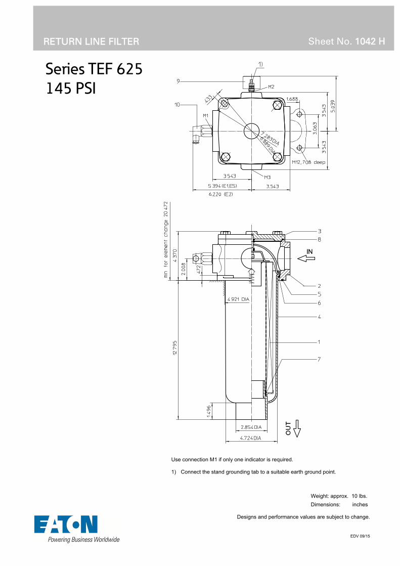
Series TEF 625
145 PSI
RETURN LINE FILTER
Sheet No. 1042 H
EDV 09/15
Use connection M1 if only one indicator is required. 1) Connect the stand grounding tab to a suitable earth ground point.
Weight: approx. 10 lbs.
Dimensions: inches Designs and performance values are subject to change.

Return Line Filter
Series TEF 625
145 PSI
Description:
Return-line TEF series filters have a working pressure up to 145 PSI. Pressure peaks can be absorbed with a sufficient safety margin.
The TEF-filters are directly mounted to the reservoir and connected to the return-line.
The filter element consists of star-shaped, pleated filter material, which is supported on the inside by a perforated core tube and is bonded to the end caps with a high-quality adhesive. The flow direction is from outside to inside. Filter elements are available down to 4 µm(c).
Eaton filter elements are suitable for all petroleum based fluids, HW-emulsions, most synthetic hydraulic fluids and lubrication oils.
Eaton filter elements are known for high intrinsic stability and an excellent filtration capability, a high dirt-retaining capacity and a long service life. Due to its practical design, the return-line filter is easy to service.
When changing the filter element, a detachable connection between the filter head and the filter bowl prevents a flow back of dirty oil into the tank.
Type index:
Complete filter: (ordering example)
TEF. 625. 10VG. 16. S. P. -. FS. 8. -. E1. O. -1 2 3 4 5 6 7 8 9 10 11 12 13
1 series: TEF = tank-mounted return-line-filter
2 nominal size: 625
3 filter-material and filter-fineness: 80G, 40G, 25G stainless steel wire mesh 25VG, 16VG, 10VG, 6VG, 3VG microglass 10P paper
4 filter element collapse rating: 16 = p 232 PSI
5 filter element design: E = without by-pass valve S = with by-pass valve p 29 PSI
6 sealing material: P = Nitrile (NBR) V = Viton (FPM)
7 filter element specification: (see catalog) - = standard VA = stainless steel IS06 = for HFC applications, see sheet-no. 31601
8 process connection: FS = SAE-flange 3000 PSI
9 process connection size: 8 = 2“
10 filter housing specification: (see catalog) - = standard IS06 = for HFC applications, see sheet-no. 31605 IS11 = for mining applications, see sheet-no. 40530
11 clogging indicator at M1: - = without O = visual, see sheet-no. 1616 E1 = pressure switch, see sheet-no. 1616 E2 = pressure switch, see sheet-no. 1616 E5 = pressure switch, see sheet-no. 1616 PA = electrical grounding connection
12 clogging indicator at M2: possible indicators see position 11 of the type index
13 clogging indicator at M3: possible indicators see position 11 of the type index
To add an indicator to your filter, use the corresponding indicator data sheet to find the indicator details and add them to the filter assembly model code.
1.2. Filter element: (ordering example)
01E. 631. 10VG. 16. S. P. - 1 2 3 4 5 6 7
1 series: 01E. = filter element according to company standard
2 nominal size: 631
3 - 7 see type index-complete filter
Accessories:
- SAE-counter flange see sheet-no 1652
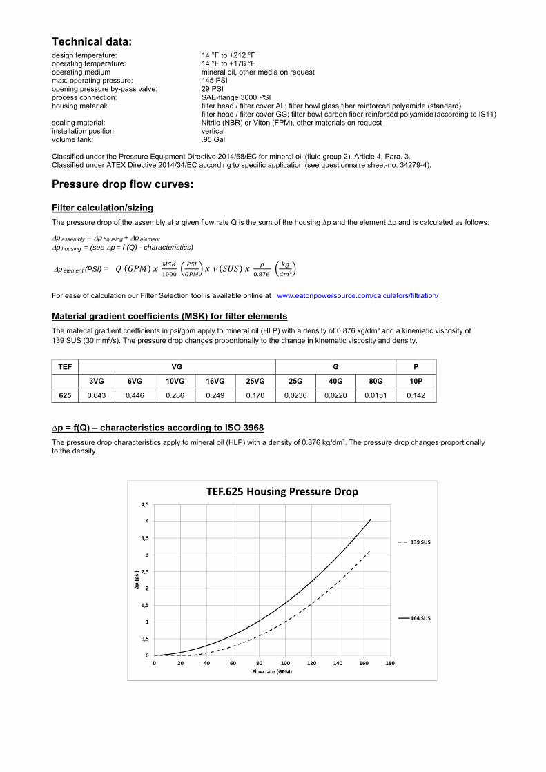
Technical data:
design temperature: 14 °F to +212 °F operating temperature: 14 °F to +176 °F operating medium mineral oil, other media on request max. operating pressure: 145 PSI opening pressure by-pass valve: 29 PSI process connection: SAE-flange 3000 PSI housing material: filter head / filter cover AL; filter bowl glass fiber reinforced polyamide (standard) filter head / filter cover GG; filter bowl carbon fiber reinforced polyamide (according to IS11) sealing material: Nitrile (NBR) or Viton (FPM), other materials on request installation position: vertical volume tank: .95 Gal
Classified under the Pressure Equipment Directive 2014/68/EC for mineral oil (fluid group 2), Article 4, Para. 3. Classified under ATEX Directive 2014/34/EC according to specific application (see questionnaire sheet-no. 34279-4).
Pressure drop flow curves:
Filter calculation/sizing
The pressure drop of the assembly at a given flow rate Q is the sum of the housing ∆p and the element ∆p and is calculated as follows:
p assembly = p housing + p element p housing = (see p = f (Q) - characteristics)
p element (PSI) = .
³
For ease of calculation our Filter Selection tool is available online at www.eatonpowersource.com/calculators/filtration/
Material gradient coefficients (MSK) for filter elements
The material gradient coefficients in psi/gpm apply to mineral oil (HLP) with a density of 0.876 kg/dm³ and a kinematic viscosity of 139 SUS (30 mm²/s). The pressure drop changes proportionally to the change in kinematic viscosity and density.
TEF VG G P
3VG 6VG 10VG 16VG 25VG 25G 40G 80G 10P
625 0.643 0.446 0.286 0.249 0.170 0.0236 0.0220 0.0151 0.142
∆p = f(Q) – characteristics according to ISO 3968
The pressure drop characteristics apply to mineral oil (HLP) with a density of 0.876 kg/dm³. The pressure drop changes proportionally to the density.
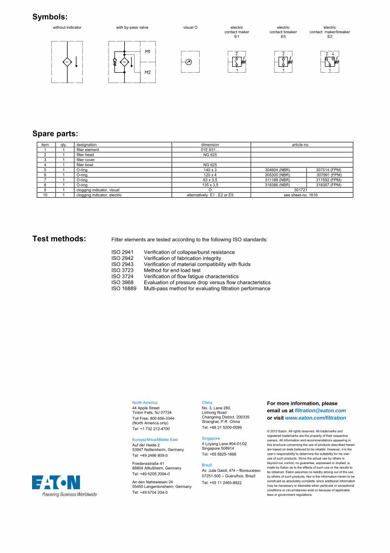
Symbols: without indicator with by-pass valve visual O electric
contact maker E1
electric contact breaker
E5
electric contact maker/breaker
E2
Spare parts: item qty. designation dimension article-no.
1 1 filter element 01E.631… 2 1 filter head NG 625 3 1 filter cover 4 1 filter bowl NG 625 5 1 O-ring 140 x 3 304604 (NBR) 307514 (FPM) 6 1 O-ring 120 x 4 305300 (NBR) 307991 (FPM) 7 1 O-ring 63 x 3,5 311189 (NBR) 311592 (FPM) 8 1 O-ring 135 x 3,5 318386 (NBR) 318387 (FPM) 9 1 clogging indicator, visual O 301721 10 1 clogging indicator, electric alternatively E1 , E2 or E5 see sheet-no. 1616
Test methods: Filter elements are tested according to the following ISO standards:
ISO 2941 Verification of collapse/burst resistance ISO 2942 Verification of fabrication integrity ISO 2943 Verification of material compatibility with fluids ISO 3723 Method for end load test ISO 3724 Verification of flow fatigue characteristics ISO 3968 Evaluation of pressure drop versus flow characteristics ISO 16889 Multi-pass method for evaluating filtration performance
North America 44 Apple Street Tinton Falls, NJ 07724
Toll Free: 800 656-3344 (North America only)
Tel: +1 732 212-4700 Europe/Africa/Middle East Auf der Heide 2 53947 Nettersheim, Germany
Tel: +49 2486 809-0
Friedensstraße 41 68804 Altlußheim, Germany
Tel: +49 6205 2094-0
An den Nahewiesen 24 55450 Langenlonsheim, Germany
Tel: +49 6704 204-0
China No. 3, Lane 280, Linhong Road Changning District, 200335 Shanghai, P.R. China
Tel: +86 21 5200-0099 Singapore 4 Loyang Lane #04-01/02 Singapore 508914
Tel: +65 6825-1668 Brazil Av. Julia Gaioli, 474 – Bonsucesso 07251-500 – Guarulhos, Brazil
Tel: +55 11 2465-8822
For more information, please email us at [email protected]
or visit www.eaton.com/filtration
© 2015 Eaton. All rights reserved. All trademarks and registered trademarks are the property of their respective owners. All information and recommendations appearing in this brochure concerning the use of products described herein are based on tests believed to be reliable. However, it is the user’s responsibility to determine the suitability for his own use of such products. Since the actual use by others is beyond our control, no guarantee, expressed or implied, is made by Eaton as to the effects of such use or the results to be obtained. Eaton assumes no liability arising out of the use by others of such products. Nor is the information herein to be construed as absolutely complete, since additional information may be necessary or desirable when particular or exceptional conditions or circumstances exist or because of applicable laws or government regulations.
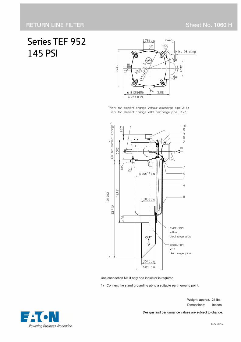
Series TEF 952
145 PSI
RETURN LINE FILTER
Sheet No. 1060 H
EDV 09/15
Use connection M1 if only one indicator is required. 1) Connect the stand grounding ab to a suitable earth ground point.
Weight: approx. 24 lbs.
Dimensions: inches Designs and performance values are subject to change.

Return Line Filter
Series TEF 952
145 PSI
Description:
Return-line TEF series filters have a working pressure up to 145 PSI. Pressure peaks can be absorbed with a sufficient safety margin.
The TEF-filters are directly mounted to the reservoir and connected to the return-line.
The filter element consists of star-shaped, pleated filter material, which is supported on the inside by a perforated core tube and is bonded to the end caps with a high-quality adhesive. The flow is from outside to inside. Filters finer than 40 µm should use disposable elements made of paper or microglass. Filter elements as fine as 5 µm(c) are available; finer filter elements on request.
Eaton filter elements are suitable for all petroleum based fluids, HW-emulsions, most synthetic hydraulic fluids and lubrication oils.
Eaton filter elements are known for high intrinsic stability and an excellent filtration capability, a high dirt-retaining capacity and a long service life. Due to its practical design, the return-line filter is easy to service.
When changing the filter element, a detachable connection between the filter head and the filter bowl prevents a flow back of dirty oil into the tank.
Type index:
Complete filter: (ordering example)
TEF. 952. 10VG. 10. S. P. -. FS. A. -.1 2 3 4 5 6 7 8 9 10
E1. O. -. -. - 11 12 13 14 15
1 series: TEF = tank-mounted return-line-filter
2 nominal size: 952
3 filter-material and filter-fineness: 80G, 40G, 25G stainless steel wire mesh 25VG, 16VG, 10VG, 6VG, 3VG microglass 10P paper
4 resistance of pressure difference for filter element: 10 = p 145 PSI
5 filter element design: E = without by-pass valve S = with by-pass valve p 29 PSI S1 = with by-pass valve p 51 PSI
6 sealing material: P = Nitrile (NBR) V = Viton (FPM)
7 filter element specification: (see catalog) - = standard VA = stainless steel IS06 = For HFC applications, see sheet-no. 31601
8 process connection: FS = SAE-flange 3000 PSI
9 process connection size: A = 3“
10 filter housing specification: (see catalog) - = standard IS06 = for HFC applications, see sheet-no. 31605 IS11 = for mining applications, see sheet-no. 40530
11 clogging indicator at M1: - = without O = visual, see sheet-no. 1616 E1 = pressure switch, see sheet-no. 1616 E2 = pressure switch, see sheet-no. 1616 E5 = pressure switch, see sheet-no. 1616
12 clogging indicator at M2: possible indicators see position 11 of the type index
13 clogging indicator at M3: possible indicators see position 11 of the type index
14 clogging indicator at M4: possible indicators see position 11 of the type index
15 discharge pipe: - = without 1 = with discharge pipe
To add an indicator to your filter, use the corresponding indicator data sheet to find the indicator details and add them to the filter assembly model code.
1.2. Filter element: (ordering example)
01E. 950. 10VG. 10. S. P. - 1 2 3 4 5 6 7
1 series: 01E. = filter element according to company standard
2 nominal size: 950
3 - 7 see type index-complete filter
Accessories:
- SAE-counter flange, see sheet-no. 1652

Technical data:
design temperature: 14 °F to +212 °F operating temperature: 14 °F to +176 °F operating medium mineral oil, other media on request max. operating pressure: 145 PSI opening pressure by-pass valve: 29 PSI, 51 PSI process connection: SAE-flange 3000 PSI housing material: filter head / filter cover AL; filter bowl glass fiber reinforced polyamide (standard) filter head / filter cover GG; filter bowl carbon fiber reinforced polyamide (according to IS11) sealing material: Nitrile (NBR) or Viton (FPM), other materials on request installation position: vertical volume tank: 2.60 Gal
Classified under the Pressure Equipment Directive 2014/68/EC for mineral oil (fluid group 2), Article 4, Para. 3. Classified under ATEX Directive 2014/34/EC according to specific application (see questionnaire sheet-no. 34279-4).
Pressure drop flow curves:
Filter calculation/sizing
The pressure drop of the assembly at a given flow rate Q is the sum of the housing ∆p and the element ∆p and is calculated as follows:
p assembly = p housing + p element p housing = (see p = f (Q) - characteristics)
p element (PSI) = .
³
For ease of calculation our Filter Selection tool is available online at www.eatonpowersource.com/calculators/filtration/
Material gradient coefficients (MSK) for filter elements
The material gradient coefficients in psi/gpm apply to mineral oil (HLP) with a density of 0.876 kg/dm³ and a kinematic viscosity of 139 SUS (30 mm²/s). The pressure drop changes proportionally to the change in kinematic viscosity and density.
TEF VG G P
3VG 6VG 10VG 16VG 25VG 25G 40G 80G 10P
952 0.364 0.253 0.162 0.141 0.096 0.0179 0.0167 0.0115 0.076
∆p = f(Q) – characteristics according to ISO 3968
The pressure drop characteristics apply to mineral oil (HLP) with a density of 0.876 kg/dm³. The pressure drop changes proportionally to the density.

Symbols: without indicator with by-pass valve visual O electric
contact maker E1
electric contact breaker
E5
electric contact maker/breaker
E2
Spare parts: item qty. designation dimension article-no.
1 1 filter element 01.E 950...
2 1 filter head
3 1 filter cover
4 1 filter bowl without discharge pipe
1 filter bowl with discharge pipe
5 1 O-ring 195 x 3,5 301831 (NBR) 306528 (FPM)
6 1 O-ring 170 x 6 304799 (NBR) 306529 (FPM)
7 1 O-ring 190 x 5 305432 (NBR) 310283 (FPM)
8 1 O-ring 78 x 10 305017 (NBR) 305552 (FPM)
9 1 clogging indicator visual O 301721
10 1 clogging indicator electric alternatively E1, E2 or E5 see sheet-no. 1616
Test methods: Filter elements are tested according to the following ISO standards:
ISO 2941 Verification of collapse/burst resistance ISO 2942 Verification of fabrication integrity ISO 2943 Verification of material compatibility with fluids ISO 3723 Method for end load test ISO 3724 Verification of flow fatigue characteristics ISO 3968 Evaluation of pressure drop versus flow characteristics ISO 16889 Multi-pass method for evaluating filtration performance
North America 44 Apple Street Tinton Falls, NJ 07724
Toll Free: 800 656-3344 (North America only)
Tel: +1 732 212-4700 Europe/Africa/Middle East Auf der Heide 2 53947 Nettersheim, Germany
Tel: +49 2486 809-0
Friedensstraße 41 68804 Altlußheim, Germany
Tel: +49 6205 2094-0
An den Nahewiesen 24 55450 Langenlonsheim, Germany
Tel: +49 6704 204-0
China No. 3, Lane 280, Linhong Road Changning District, 200335 Shanghai, P.R. China
Tel: +86 21 5200-0099 Singapore 4 Loyang Lane #04-01/02 Singapore 508914
Tel: +65 6825-1668 Brazil Av. Julia Gaioli, 474 – Bonsucesso 07251-500 – Guarulhos, Brazil
Tel: +55 11 2465-8822
For more information, please email us at [email protected]
or visit www.eaton.com/filtration
© 2015 Eaton. All rights reserved. All trademarks and registered trademarks are the property of their respective owners. All information and recommendations appearing in this brochure concerning the use of products described herein are based on tests believed to be reliable. However, it is the user’s responsibility to determine the suitability for his own use of such products. Since the actual use by others is beyond our control, no guarantee, expressed or implied, is made by Eaton as to the effects of such use or the results to be obtained. Eaton assumes no liability arising out of the use by others of such products. Nor is the information herein to be construed as absolutely complete, since additional information may be necessary or desirable when particular or exceptional conditions or circumstances exist or because of applicable laws or government regulations.

Series TEFB 41
145 PSI
RETURN LINE FILTER, with breather filter
Sheet No. 1041 G
EDV 09/15
Weight: approx. 2.0 lbs.
Dimensions: inches Designs and performance values are subject to change.
When selecting only one indicator, use connection M2.

Return Line Filter
Series TEFB 41
145 PSI
Description:
Return-line filter series TEFB 41 have a working pressure up to 145 PSI.
The TEFB filters are directly mounted to the reservoir and connected to the return-line. No connection is needed for the built-in air filter. The air filter has a 10µm disposable element.
The filter element consists of star-shaped, pleated filter material, which is supported on the inside by a perforated core tube and is bonded to the end caps with a high-quality adhesive. The flow direction is from outside to inside.
Eaton filter elements are known for a high intrinsic stability and an excellent filtration capability, a high dirt-retaining capacity and a long service life.
For filtration finer than 40 μm use the disposable elements made of microglass. Filter elements as fine as 5 μm(c) are available; finer filter elements on request.
Eaton filter elements can be used for petroleum-based fluids, HW emulsions, water glycols, most synthetic fluids and lubrication fluids. Consult factory for specific fluid applications.
When changing the filter element, a detachable connection between the filter head and the filter bowl prevents dirty oil from flowing into the tank.
1. Type index:
1.1. Complete filter: (ordering example)
TEFB.41.10VG.16. S. P. -. UG. 3. -. E1. O1 2 3 4 5 6 7 8 9 10 11 12
TEFB.41.10VG.30. E. P. -. UG. 3. -. E1. O1 2 3 4 5 6 7 8 9 10 11 12
1 series: TEFB = tank-mounted return-line-filter with breather filter
2 nominal size: 41
3 filter-material and filter-fineness: 80G, 40G, 25G stainless steel wire mesh 25VG, 16VG, 10VG, 6VG, 3VG microglass 10P paper (only with 01E.41)
4 filter element collapse rating: 16 = 01E.41 for p 232 PSI (standard with by-pass valve) 30 = 01E.60 for p 435 PSI (standard without by-pass valve)
5 filter element design: S = with by-pass valve ( 01E.41) p 29 PSI E = without by-pass valve ( 01E.60)
6 sealing material: P = Nitrile (NBR) V = Viton (FPM)
7 filter element specification: (see catalog) - = standard VA = stainless steel IS06 = for HFC application, see sheet-no. 31601
8 process connection: UG = thread connection
9 process connection size: 3 = - 8 SAE
10 filter housing specification: (see catalog) - = standard IS06 = for HFC application, see sheet-no. 31605
11 clogging indicator at M1: - = without O = visual, see sheet-no. 1616 E1 = pressure switch, see sheet-no. 1616 E2 = pressure switch, see sheet-no. 1616 E5 = pressure switch, see sheet-no. 1616
12 clogging indicator at M2: possible indicators see position 11 of the type index
To add an indicator to your filter, use the corresponding indicator data sheet to find the indicator details and add them to the filter assembly model code.
1.2. Filter element: (ordering example)
01E. 41. 10VG. 16. S. P. - 1 2 3 4 5 6 7
01E. 60. 10VG. 30. E. P. - 1 2 3 4 5 6 7
1 series: 01E. = filter element according to company standard
2 nominal size: 41, 60
3 - 7 see type index-complete filter

Technical data:
design temperature: 14 °F to +212 °F operating temperature: 14 °F to +176 °F operating medium mineral oil, other media on request max. operating pressure: 145 PSI opening pressure by-pass valve: 29 PSI process connection: thread connection housing material standard: Al-cast, glass fiber reinforced polyamide sealing material: Nitrile (NBR) or Viton (FPM), other materials on request installation position: vertical volume tank: .05 Gal.
Classified under the Pressure Equipment Directive 2014/68/EC for mineral oil (fluid group 2), Article 4, Para. 3. Classified under ATEX Directive 2014/34/EC according to specific application (see questionnaire sheet-no. 34279-4).
Pressure drop flow curves:
Filter calculation/sizing
The pressure drop of the assembly at a given flow rate Q is the sum of the housing ∆p and the element ∆p and is calculated as follows:
p assembly = p housing + p element p housing = (see p = f (Q) - characteristics)
p element (PSI) = .
³
For ease of calculation our Filter Selection tool is available online at www.eatonpowersource.com/calculators/filtration/
Material gradient coefficients (MSK) for filter elements
The material gradient coefficients in psi/gpm apply to mineral oil (HLP) with a density of 0.876 kg/dm³ and a kinematic viscosity of 139 SUS (30 mm²/s). The pressure drop changes proportionally to the change in kinematic viscosity and density.
TEFB VG G P
3VG 6VG 10VG 16VG 25VG 25G 40G 80G 10P
41 (without bypass) 6.748 4.685 2.999 2.577 1.760 0.2002 0.1868 0.1280 1.469
41 (with bypass) 6.748 4.685 2.999 2.577 1.760 0.2002 0.1868 0.1280 -
∆p = f(Q) – characteristics according to ISO 3968
The pressure drop characteristics apply to mineral oil (HLP) with a density of 0.876 kg/dm³. The pressure drop changes proportionally to the density.

Symbols: without indicator with by-pass valve visual O electrical
contact maker E1
electrical contact breaker
E5
electrical contact maker/breaker
E2
Spare parts: item qty. designation dimension article-no.
1 1 filter element with by-pass 01E.41…
filter element without by-pass 01E.60…
2 1 filter head TEFB 41 - 55 308751
3 1 filter cover M 60 x 2 303621
4 1 filter bowl TEF 41 306673
5 1 O-ring 56 x 3 305072 (NBR) 305322 (FPM)
6 1 O-ring 50 x 2,5 305239 (NBR) 305321 (FPM)
7 1 O-ring 22 x 3,5 304341 (NBR) 304392 (FPM)
8 1 gasket .08 thick 303039
9 1 spring DA = 40 304982
10 1 clogging indicator visual O 301721
11 1 clogging indicator electrical alternatively E1, E2 or E5 see sheet-no. 1616
12 1 filter element breather 01BFE.70 301865
13 1 protection cap 305312
Test methods: Filter elements are tested according to the following ISO standards:
ISO 2941 Verification of collapse/burst resistance ISO 2942 Verification of fabrication integrity ISO 2943 Verification of material compatibility with fluids ISO 3723 Method for end load test ISO 3724 Verification of flow fatigue characteristics ISO 3968 Evaluation of pressure drop versus flow characteristics ISO 16889 Multi-pass method for evaluating filtration performance
North America 44 Apple Street Tinton Falls, NJ 07724
Toll Free: 800 656-3344 (North America only)
Tel: +1 732 212-4700 Europe/Africa/Middle East Auf der Heide 2 53947 Nettersheim, Germany
Tel: +49 2486 809-0
Friedensstraße 41 68804 Altlußheim, Germany
Tel: +49 6205 2094-0
An den Nahewiesen 24 55450 Langenlonsheim, Germany
Tel: +49 6704 204-0
China No. 3, Lane 280, Linhong Road Changning District, 200335 Shanghai, P.R. China
Tel: +86 21 5200-0099 Singapore 4 Loyang Lane #04-01/02 Singapore 508914
Tel: +65 6825-1668 Brazil Av. Julia Gaioli, 474 – Bonsucesso 07251-500 – Guarulhos, Brazil
Tel: +55 11 2465-8822
For more information, please email us at [email protected]
or visit www.eaton.com/filtration
© 2015 Eaton. All rights reserved. All trademarks and registered trademarks are the property of their respective owners. All information and recommendations appearing in this brochure concerning the use of products described herein are based on tests believed to be reliable. However, it is the user’s responsibility to determine the suitability for his own use of such products. Since the actual use by others is beyond our control, no guarantee, expressed or implied, is made by Eaton as to the effects of such use or the results to be obtained. Eaton assumes no liability arising out of the use by others of such products. Nor is the information herein to be construed as absolutely complete, since additional information may be necessary or desirable when particular or exceptional conditions or circumstances exist or because of applicable laws or government regulations.

Series TEFB 55-120
145 PSI
RETURN LINE FILTER, with breather filter
Sheet No. 1061 M
EDV 09/15
Dimensions: inches Designs and performance values are subject to change.
Dimensions:
type TEFB 55 TEFB 70 TEFB 120 connection - 8 SAE -12 SAE -16 SAE
A 10.24 10.24 11.42 B 7.56 7.56 8.27 C 10.63 10.63 11.81 D 1.77 1.77 2.56 E .94 .94 1.18 F 2.05 2.05 2.76 G .87 .87 .94 H 2.38 2.38 3.09 J 2.40 2.40 3.11 K 1.25 1.25 1.65
weight 2.20 lbs. 2.20 lbs. 3.30 lbs. volume tank .08 Gal. .08 Gal. .15 Gal.
When selecting only one indicator, use connection M2. 1) Connect the stand grounding tab to a suitable earth ground point.

Return Line Filter
Series TEFB 55-120
145 PSI
Description:
Return-line filter series TEFB 55-120 have a working pressure up to 145 PSI.
The TEFB filters are directly mounted to the reservoir and connected to the return-line. No connection is needed for the built-in air filter. The air filter has a 10µm disposable element.
The filter element consists of star-shaped, pleated filter material, which is supported on the inside by a perforated core tube and is bonded to the end caps with a high-quality adhesive. The flow direction is from outside to inside.
Eaton filter elements are known for a high intrinsic stability and an excellent filtration capability, a high dirt-retaining capacity and a long service life.
For filtration finer than 40 μm use the disposable elements made of microglass. Filter elements as fine as 5 μm(c) are available; finer filter elements on request.
Eaton filter elements can be used for petroleum-based fluids, HW emulsions, water glycols, most synthetic fluids and lubrication fluids. Consult factory for specific fluid applications.
When changing the filter element, a detachable connection between the filter head and the filter bowl prevents dirty oil from flowing into the tank.
1. Type index:
1.1. Complete filter: (ordering example)
TEFB. 120. 10VG.16. S. P. -. UG. 5. -. E1. O. 11 2 3 4 5 6 7 8 9 10 11 12 13
1 series: TEFB = tank-mounted return-line-filter with breather filter
2 nominal size: 55, 70, 120
3 filter-material and filter-fineness: 80G, 40G, 25G stainless steel wire mesh 25VG, 16VG, 10VG, 6VG, 3VG microglass 10P paper
4 filter element collapse rating: 16 = p 232 PSI
5 filter element design: E = without by-pass valve S = with by-pass valve p 29 PSI
6 sealing material: P = Nitrile (NBR) V = Viton (FPM)
7 filter element specification: (see catalog) - = standard VA = stainless steel IS06 = for HFC application, see sheet-no. 31601
8 process connection: UG = thread connection
9 process connection size: 3 = - 8 SAE (TEFB 55) 4 = -12 SAE (TEFB 70) 5 = -16 SAE (TEFB 120)
10 filter housing specification: (see catalog) - = standard IS06 = for HFC application, see sheet-no. 31605
IS11 = for filter head and filter cover, see sheet-no. 40530
11 clogging indicator at M1: - = without O = visual, see sheet-no. 1616 E1 = pressure switch, see sheet-no. 1616 E2 = pressure switch, see sheet-no. 1616 E5 = pressure switch, see sheet-no. 1616 PA = ground connection
12 clogging indicator at M2: possible indicators see position 11 of the type index
13 oil separator: - = without 1 = with oil separator
To add an indicator to your filter, use the corresponding indicator data sheet to find the indicator details and add them to the filter assembly model code.
1.2. Filter element: (ordering example)
01E. 120. 10VG. 16. S. P. - 1 2 3 4 5 6 7
1 series: 01E. = filter element according to company standard
2 nominal size: 70, 120
3 - 7 see type index-complete filter

Technical data:
design temperature: 14 °F to +212 °F operating temperature: 14 °F to +176 °F operating medium mineral oil, other media on request max. operating pressure: 145 PSI opening pressure by-pass valve: 29 PSI process connection: thread connection housing material standard: filter head AL, filter cover / filter bowl glass fibre reinforced polyamide housing material IS11, category M2: filter head GG, filter cover steel / filter bowl carbon fibre reinforced polyamide housing material IS11, category 2: filter head AL, filter cover / filter bowl carbon fibre reinforced polyamide sealing material: Nitrile (NBR) or Viton (FPM), other materials on request installation position: vertical
Classified under the Pressure Equipment Directive 2014/68/EC for mineral oil (fluid group 2), Article 4, Para. 3. Classified under ATEX Directive 2014/34/EC according to specific application (see questionnaire sheet-no. 34279-4).
Pressure drop flow curves:
Filter calculation/sizing
The pressure drop of the assembly at a given flow rate Q is the sum of the housing ∆p and the element ∆p and is calculated as follows:
p assembly = p housing + p element p housing = (see p = f (Q) - characteristics)
p element (PSI) = .
³
For ease of calculation our Filter Selection tool is available online at www.eatonpowersource.com/calculators/filtration/
Material gradient coefficients (MSK) for filter elements
The material gradient coefficients in psi/gpm apply to mineral oil (HLP) with a density of 0.876 kg/dm³ and a kinematic viscosity of 139 SUS (30 mm²/s). The pressure drop changes proportionally to the change in kinematic viscosity and density.
TEFB VG G P
3VG 6VG 10VG 16VG 25VG 25G 40G 80G 10P
55 3.535 2.454 1.571 1.368 0.935 0.1196 0.1117 0.0765 0.797
70 3.535 2.454 1.571 1.368 0.935 0.1196 0.1117 0.0765 0.797
120 3.162 2.195 1.405 1.224 0.836 0.1144 0.1068 0.0731 0.690
∆p = f(Q) – characteristics according to ISO 3968
The pressure drop characteristics apply to mineral oil (HLP) with a density of 0.876 kg/dm³. The pressure drop changes proportionally to the density.
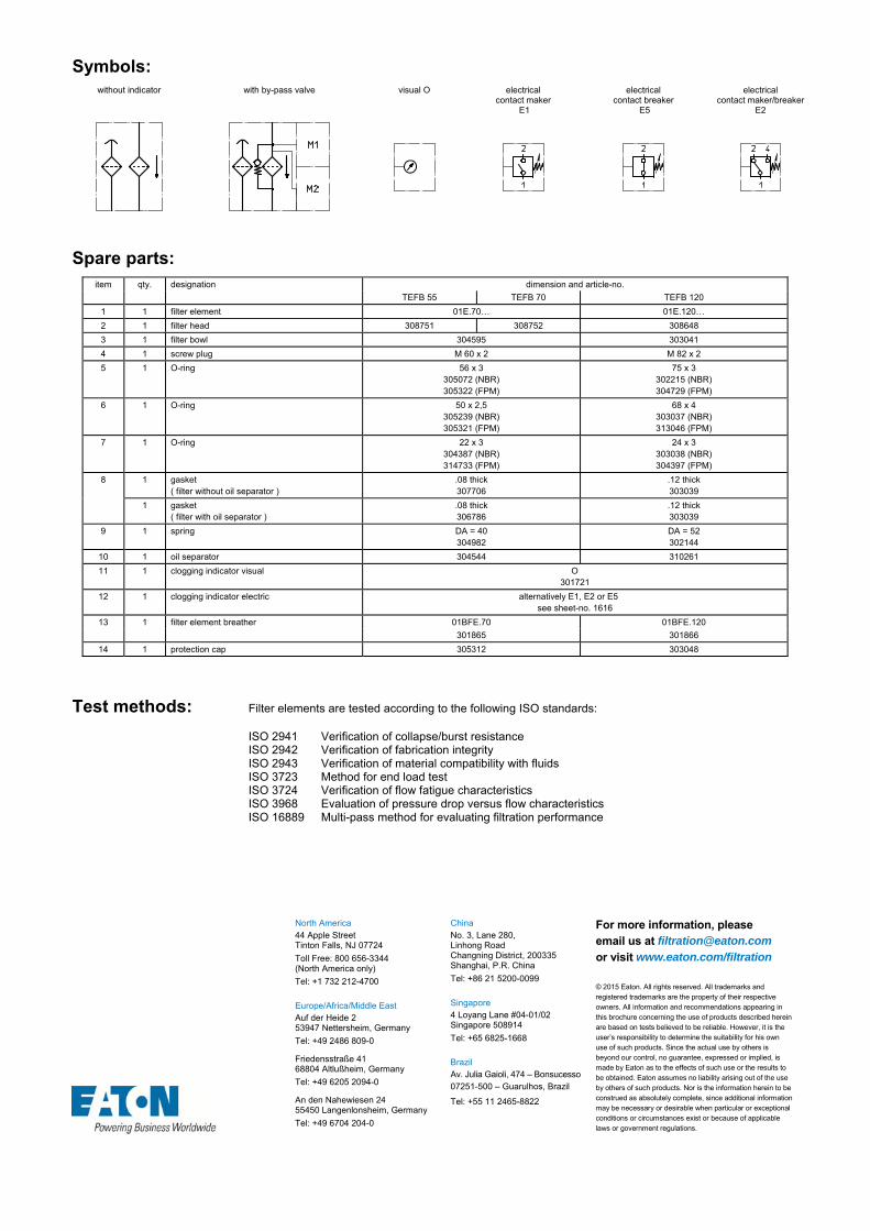
Symbols: without indicator with by-pass valve visual O electrical
contact maker E1
electrical contact breaker
E5
electrical contact maker/breaker
E2
Spare parts: item qty. designation dimension and article-no.
TEFB 55 TEFB 70 TEFB 120
1 1 filter element 01E.70… 01E.120…
2 1 filter head 308751 308752 308648
3 1 filter bowl 304595 303041
4 1 screw plug M 60 x 2 M 82 x 2
5 1 O-ring 56 x 3 305072 (NBR) 305322 (FPM)
75 x 3 302215 (NBR) 304729 (FPM)
6 1 O-ring 50 x 2,5 305239 (NBR) 305321 (FPM)
68 x 4 303037 (NBR) 313046 (FPM)
7 1 O-ring 22 x 3 304387 (NBR) 314733 (FPM)
24 x 3 303038 (NBR) 304397 (FPM)
8 1 gasket ( filter without oil separator )
.08 thick 307706
.12 thick 303039
1 gasket ( filter with oil separator )
.08 thick 306786
.12 thick 303039
9 1 spring DA = 40 304982
DA = 52 302144
10 1 oil separator 304544 310261
11 1 clogging indicator visual O 301721
12 1 clogging indicator electric alternatively E1, E2 or E5 see sheet-no. 1616
13 1 filter element breather 01BFE.70 01BFE.120
301865 301866
14 1 protection cap 305312 303048
Test methods: Filter elements are tested according to the following ISO standards:
ISO 2941 Verification of collapse/burst resistance ISO 2942 Verification of fabrication integrity ISO 2943 Verification of material compatibility with fluids ISO 3723 Method for end load test ISO 3724 Verification of flow fatigue characteristics ISO 3968 Evaluation of pressure drop versus flow characteristics ISO 16889 Multi-pass method for evaluating filtration performance
North America 44 Apple Street Tinton Falls, NJ 07724
Toll Free: 800 656-3344 (North America only)
Tel: +1 732 212-4700 Europe/Africa/Middle East Auf der Heide 2 53947 Nettersheim, Germany
Tel: +49 2486 809-0
Friedensstraße 41 68804 Altlußheim, Germany
Tel: +49 6205 2094-0
An den Nahewiesen 24 55450 Langenlonsheim, Germany
Tel: +49 6704 204-0
China No. 3, Lane 280, Linhong Road Changning District, 200335 Shanghai, P.R. China
Tel: +86 21 5200-0099 Singapore 4 Loyang Lane #04-01/02 Singapore 508914
Tel: +65 6825-1668 Brazil Av. Julia Gaioli, 474 – Bonsucesso 07251-500 – Guarulhos, Brazil
Tel: +55 11 2465-8822
For more information, please email us at [email protected]
or visit www.eaton.com/filtration
© 2015 Eaton. All rights reserved. All trademarks and registered trademarks are the property of their respective owners. All information and recommendations appearing in this brochure concerning the use of products described herein are based on tests believed to be reliable. However, it is the user’s responsibility to determine the suitability for his own use of such products. Since the actual use by others is beyond our control, no guarantee, expressed or implied, is made by Eaton as to the effects of such use or the results to be obtained. Eaton assumes no liability arising out of the use by others of such products. Nor is the information herein to be construed as absolutely complete, since additional information may be necessary or desirable when particular or exceptional conditions or circumstances exist or because of applicable laws or government regulations.
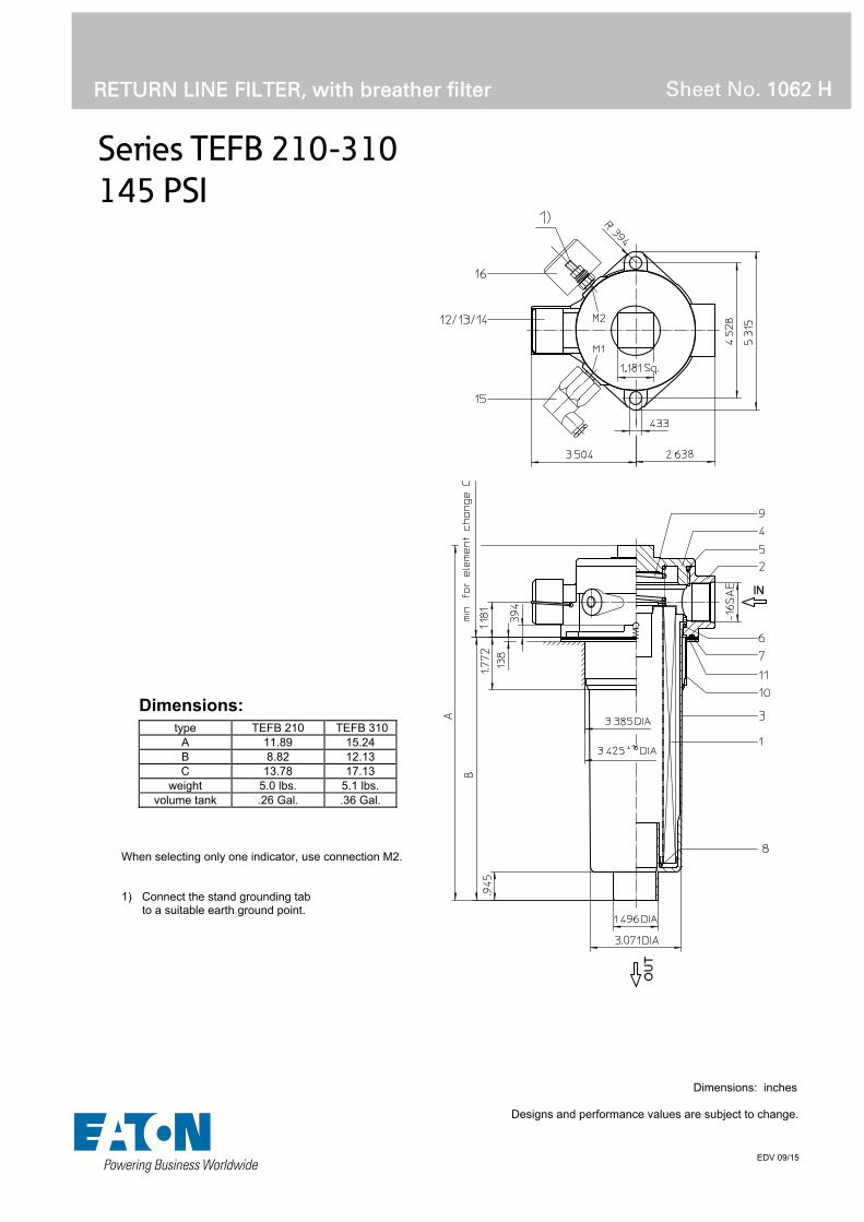
Series TEFB 210-310
145 PSI
RETURN LINE FILTER, with breather filter
Sheet No. 1062 H
EDV 09/15
Dimensions: inches Designs and performance values are subject to change.
Dimensions:
type TEFB 210 TEFB 310 A 11.89 15.24 B 8.82 12.13 C 13.78 17.13
weight 5.0 lbs. 5.1 lbs. volume tank .26 Gal. .36 Gal.
When selecting only one indicator, use connection M2. 1) Connect the stand grounding tab to a suitable earth ground point.

Return Line Filter
Series TEFB 210-310
145 PSI
Description:
Return-line filter series TEFB 210-310 have a working pressure up to 145 PSI.
The TEFB filters are directly mounted to the reservoir and connected to the return-line. No connection is needed for the built-in air filter. The air filter has a 10µm disposable element.
The filter element consists of star-shaped, pleated filter material, which is supported on the inside by a perforated core tube and is bonded to the end caps with a high-quality adhesive. The flow direction is from outside to inside.
Eaton filter elements are known for a high intrinsic stability and an excellent filtration capability, a high dirt-retaining capacity and a long service life.
For filtration finer than 40 μm use the disposable elements made of microglass. Filter elements as fine as 5 μm(c) are available; finer filter elements on request.
Eaton filter elements can be used for petroleum-based fluids, HW emulsions, water glycols, most synthetic fluids and lubrication fluids. Consult factory for specific fluid applications.
When changing the filter element, a detachable connection between the filter head and the filter bowl prevents dirty oil from flowing into the tank.
1. Type index:
1.1. Complete filter: (ordering example)
TEFB. 210. 10VG.16. S. P. -. UG. 5. -. E1. O. 11 2 3 4 5 6 7 8 9 10 11 12 13
1 series: TEFB = tank-mounted return-line-filter with breather filter
2 nominal size: 310, 310
3 filter-material and filter-fineness: 80G, 40G, 25G stainless steel wire mesh 25VG, 16VG, 10VG, 6VG, 3VG microglass 10P paper
4 filter element collapse rating: 16 = p 232 PSI
5 filter element design: E = without by-pass valve S = with by-pass valve p 29 PSI
6 sealing material: P = Nitrile (NBR) V = Viton (FPM)
7 filter element specification: (see catalog) - = standard VA = stainless steel IS06 = for HFC application, see sheet-no. 31601
8 process connection: UG = thread connection
9 process connection size: 5 = -16 SAE
10 filter housing specification: (see catalog) - = standard IS06 = for HFC application, see sheet-no. 31605
IS11 = for filter head and filter cover, see sheet-no. 40530
11 clogging indicator at M1: - = without O = visual, see sheet-no. 1616 E1 = pressure switch, see sheet-no. 1616 E2 = pressure switch, see sheet-no. 1616 E5 = pressure switch, see sheet-no. 1616 PA = ground connection
12 clogging indicator at M2: possible indicators see position 11 of the type index
13 oil separator: - = without 1 = with oil separator
To add an indicator to your filter, use the corresponding indicator data sheet to find the indicator details and add them to the filter assembly model code.
1.2. Filter element: (ordering example)
01E. 210. 10VG. 16. S. P. - 1 2 3 4 5 6 7
1 series: 01E. = filter element according to company standard
2 nominal size: 210, 320
3 - 7 see type index-complete filter

Technical data:
design temperature: 14 °F to +212 °F operating temperature: 14 °F to +176 °F operating medium mineral oil, other media on request max. operating pressure: 145 PSI opening pressure by-pass valve: 29 PSI process connection: thread connection housing material standard: filter head AL, filter cover / filter bowl glass fibre reinforced polyamide housing material IS11, category M2: filter head GG, filter cover steel / filter bowl carbon fibre reinforced polyamide housing material IS11, category 2: filter head AL, filter cover / filter bowl carbon fibre reinforced polyamide sealing material: Nitrile (NBR) or Viton (FPM), other materials on request installation position: vertical
Classified under the Pressure Equipment Directive 2014/68/EC for mineral oil (fluid group 2), Article 4, Para. 3. Classified under ATEX Directive 2014/34/EC according to specific application (see questionnaire sheet-no. 34279-4).
Pressure drop flow curves:
Filter calculation/sizing
The pressure drop of the assembly at a given flow rate Q is the sum of the housing ∆p and the element ∆p and is calculated as follows:
p assembly = p housing + p element p housing = (see p = f (Q) - characteristics)
p element (PSI) = .
³
For ease of calculation our Filter Selection tool is available online at www.eatonpowersource.com/calculators/filtration/
Material gradient coefficients (MSK) for filter elements
The material gradient coefficients in psi/gpm apply to mineral oil (HLP) with a density of 0.876 kg/dm³ and a kinematic viscosity of 139 SUS (30 mm²/s). The pressure drop changes proportionally to the change in kinematic viscosity and density.
TEFB VG G P
3VG 6VG 10VG 16VG 25VG 25G 40G 80G 10P
210 1.600 1.111 0.711 0.619 0.423 0.0588 0.0549 0.0376 0.353
310 1.148 0.797 0.510 0.444 0.304 0.0337 0.0314 0.0215 0.253
∆p = f(Q) – characteristics according to ISO 3968
The pressure drop characteristics apply to mineral oil (HLP) with a density of 0.876 kg/dm³. The pressure drop changes proportionally to the density.

Symbols: without indicator with by-pass valve visual O electric
contact maker E1
electric contact breaker
E5
electric contact maker/breaker
E2
Spare parts: item qty. designation dimension
TEFB 210 TEFB 310
1 1 filter element 01.E 210… 01E.320…
2 1 filter head TNR 100 313952
3 1 filter bowl NG 210 304518
NG 310 305471
4 1 filter cover M 92 x 3
317014
5 1 O-ring 82 x 3,5 304403 (NBR) 308745 (FPM)
6 1 O-ring 75 x 3 302215 (NBR) 304729 (FPM)
7 1 O-ring 95 x 3 305808 (NBR) 304828 (FPM)
8 1 O-ring 40 x 3 304991 (NBR) 304997 (FPM)
9 1 spring DA = 52 305053
10 1 oil separator
11 1 gasket (with execution oil separator) .078 thick 325389
12 1 filter element breather 01BFE. 120 301866
13 1 protection cap 303048
14 1 clip 303046
15 1 clogging indicator electric alternatively E1, E2 or E5 see sheet-no. 1616
16 1 clogging indicator visual O 301721
Test methods: Filter elements are tested according to the following ISO standards:
ISO 2941 Verification of collapse/burst resistance ISO 2942 Verification of fabrication integrity ISO 2943 Verification of material compatibility with fluids ISO 3723 Method for end load test ISO 3724 Verification of flow fatigue characteristics ISO 3968 Evaluation of pressure drop versus flow characteristics ISO 16889 Multi-pass method for evaluating filtration performance
North America 44 Apple Street Tinton Falls, NJ 07724
Toll Free: 800 656-3344 (North America only)
Tel: +1 732 212-4700 Europe/Africa/Middle East Auf der Heide 2 53947 Nettersheim, Germany
Tel: +49 2486 809-0
Friedensstraße 41 68804 Altlußheim, Germany
Tel: +49 6205 2094-0
An den Nahewiesen 24 55450 Langenlonsheim, Germany
Tel: +49 6704 204-0
China No. 3, Lane 280, Linhong Road Changning District, 200335 Shanghai, P.R. China
Tel: +86 21 5200-0099 Singapore 4 Loyang Lane #04-01/02 Singapore 508914
Tel: +65 6825-1668 Brazil Av. Julia Gaioli, 474 – Bonsucesso 07251-500 – Guarulhos, Brazil
Tel: +55 11 2465-8822
For more information, please email us at [email protected]
or visit www.eaton.com/filtration
© 2015 Eaton. All rights reserved. All trademarks and registered trademarks are the property of their respective owners. All information and recommendations appearing in this brochure concerning the use of products described herein are based on tests believed to be reliable. However, it is the user’s responsibility to determine the suitability for his own use of such products. Since the actual use by others is beyond our control, no guarantee, expressed or implied, is made by Eaton as to the effects of such use or the results to be obtained. Eaton assumes no liability arising out of the use by others of such products. Nor is the information herein to be construed as absolutely complete, since additional information may be necessary or desirable when particular or exceptional conditions or circumstances exist or because of applicable laws or government regulations.

Series TNRS 101
145 PSI
RETURN LINE FILTER, with suction connection
Sheet No. 1070 H
EDV 09/15
Weight: approx. 4.62 lbs.
Dimensions: inches Designs and performance values are subject to change.

1. Type index:
1.1. Complete filter: (ordering example)
TNRS. 101. 10VG.10.B. P. -. UG. 5. -. S2,5. Z. O. E21 2 3 4 5 6 7 8 9 10 11 12 13 14
1 series: TNRS = tank-mounted return-line filter with suction connection
2 nominal size: 101
3 filter-material and filter-fineness: 80G, 40G, 25G stainless steel wire mesh 25VG, 16VG, 10VG, 6VG, 3VG microglass 10P paper
4 filter element collapse rating: 10 = p 145 PSI
5 filter element design: B = both sides open
6 sealing material: P = Nitrile (NBR) V = Viton (FPM)
7 filter element specification: - = standard VA = stainless steel
8 process connection: UG = thread connection
9 process connection size: 5 = -16 SAE
10 filter housing specification: - = standard
11 internal valve: S2,5 = with by-pass valve p 36 PSI
12 suction valve: Z = with suction valve
13 clogging indicator at M1: - = without O = visual, see sheet-no. 1616 E1 = pressure switch, see sheet-no. 1616 E2 = pressure switch, see sheet-no. 1616 E5 = pressure switch, see sheet-no. 1616
14 preload pressure indicator at M2: - = without E2 = pressure switch, see sheet-no. 1616
To add an indicator to your filter, use the corresponding indicator data sheet to find the indicator details and add them to the filter assembly model code.
1.2. Filter element: (ordering example)
01NR. 100. 10VG. 10. B. P. - 1 2 3 4 5 6 7
1 series: 01NR. = standard-return-line filter element according to
DIN 24550, T4
2 nominal size: 100
3 - 7 see type index-complete filter
Return Line Filter
Series TNRS 101
145 PSI
Description:
Return-line filter series TNRS 101 have a working pressure up to 145 PSI.
TNRS series are tank-top mounted in-line filters. In addition to the return-line connection, they have a suction connection on the clean-side. This suction connection has a preload pressure (fitting pressure) of 7.25 PSI.
This combination, return-line and suction filter, is for hydraulic circuits which are equipped with a minimum 2 feed pumps (2 hydraulic circuits). The preload suction connection is for the full volume flow filtration of the pump with the smaller volume flow.
The filter element according to DIN 24550, T4 consists of star-shaped, pleated filter material, which is supported on the inside by a perforated core tube and is bonded to the end caps with a high-quality adhesive. The flow direction is from outside to inside. Filter elements are available down to 4 µm(c).
Eaton filter elements are known for high intrinsic stability and an excellent filtration capability, a high dirt-retaining capacity and a long service life.
Eaton filter elements can be used for petroleum-based fluids, HW emulsions, water glycols, most synthetic fluids and lubrication fluids. Consult factory for specific fluid applications.
When changing the filter element, a detachable connection between the filter head and the filter bowl prevents a flow back of dirty oil into the tank.
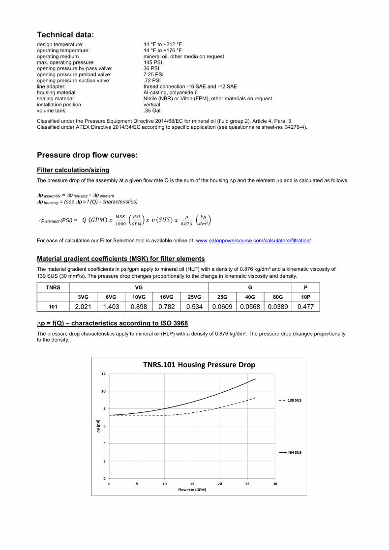
Technical data:
design temperature: 14 °F to +212 °F operating temperature: 14 °F to +176 °F operating medium mineral oil, other media on request max. operating pressure: 145 PSI opening pressure by-pass valve: 36 PSI opening pressure preload valve: 7.25 PSI opening pressure suction valve: .72 PSI line adapter: thread connection -16 SAE and -12 SAE housing material: Al-casting, polyamide 6 sealing material: Nitrile (NBR) or Viton (FPM), other materials on request installation position: vertical volume tank: .35 Gal.
Classified under the Pressure Equipment Directive 2014/68/EC for mineral oil (fluid group 2), Article 4, Para. 3. Classified under ATEX Directive 2014/34/EC according to specific application (see questionnaire sheet-no. 34279-4).
Pressure drop flow curves:
Filter calculation/sizing
The pressure drop of the assembly at a given flow rate Q is the sum of the housing ∆p and the element ∆p and is calculated as follows:
p assembly = p housing + p element p housing = (see p = f (Q) - characteristics)
p element (PSI) = .
³
For ease of calculation our Filter Selection tool is available online at www.eatonpowersource.com/calculators/filtration/
Material gradient coefficients (MSK) for filter elements
The material gradient coefficients in psi/gpm apply to mineral oil (HLP) with a density of 0.876 kg/dm³ and a kinematic viscosity of 139 SUS (30 mm²/s). The pressure drop changes proportionally to the change in kinematic viscosity and density.
TNRS VG G P
3VG 6VG 10VG 16VG 25VG 25G 40G 80G 10P
101 2.021 1.403 0.898 0.782 0.534 0.0609 0.0568 0.0389 0.477
∆p = f(Q) – characteristics according to ISO 3968
The pressure drop characteristics apply to mineral oil (HLP) with a density of 0.876 kg/dm³. The pressure drop changes proportionally to the density.
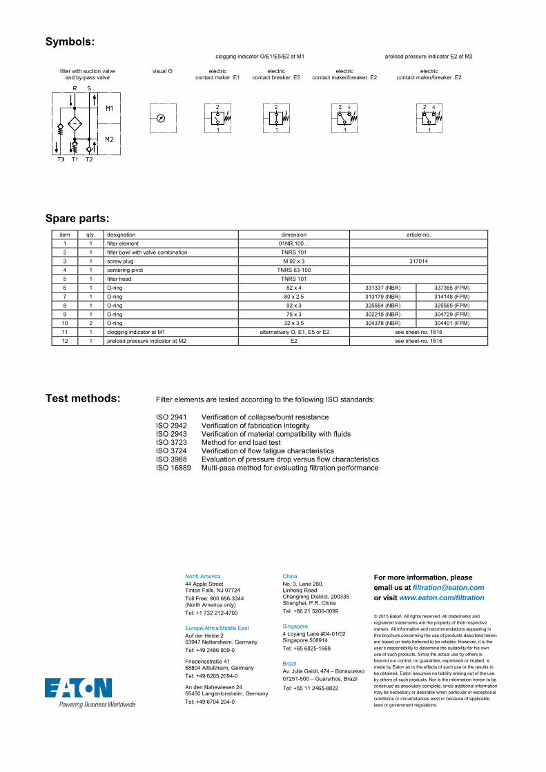
Symbols: clogging indicator O/E1/E5/E2 at M1
preload pressure indicator E2 at M2
filter with suction valve
and by-pass valve visual O electric
contact maker E1electric
contact breaker E5electric
contact maker/breaker E2 electric
contact maker/breaker E2
Spare parts: item qty. designation dimension article-no.
1 1 filter element 01NR.100…
2 1 filter bowl with valve combination TNRS 101
3 1 screw plug M 92 x 3 317014
4 1 centering pivot TNRS 63-100
5 1 filter head TNRS 101
6 1 O-ring 82 x 4 331337 (NBR) 337365 (FPM)
7 1 O-ring 80 x 2,5 313179 (NBR) 314148 (FPM)
8 1 O-ring 92 x 3 325584 (NBR) 325585 (FPM)
9 1 O-ring 75 x 3 302215 (NBR) 304729 (FPM)
10 2 O-ring 32 x 3,5 304378 (NBR) 304401 (FPM)
11 1 clogging indicator at M1 alternatively O, E1, E5 or E2 see sheet-no. 1616
12 1 preload pressure indicator at M2 E2 see sheet-no. 1616
Test methods: Filter elements are tested according to the following ISO standards:
ISO 2941 Verification of collapse/burst resistance ISO 2942 Verification of fabrication integrity ISO 2943 Verification of material compatibility with fluids ISO 3723 Method for end load test ISO 3724 Verification of flow fatigue characteristics ISO 3968 Evaluation of pressure drop versus flow characteristics ISO 16889 Multi-pass method for evaluating filtration performance
North America 44 Apple Street Tinton Falls, NJ 07724
Toll Free: 800 656-3344 (North America only)
Tel: +1 732 212-4700 Europe/Africa/Middle East Auf der Heide 2 53947 Nettersheim, Germany
Tel: +49 2486 809-0
Friedensstraße 41 68804 Altlußheim, Germany
Tel: +49 6205 2094-0
An den Nahewiesen 24 55450 Langenlonsheim, Germany
Tel: +49 6704 204-0
China No. 3, Lane 280, Linhong Road Changning District, 200335 Shanghai, P.R. China
Tel: +86 21 5200-0099 Singapore 4 Loyang Lane #04-01/02 Singapore 508914
Tel: +65 6825-1668 Brazil Av. Julia Gaioli, 474 – Bonsucesso 07251-500 – Guarulhos, Brazil
Tel: +55 11 2465-8822
For more information, please email us at [email protected]
or visit www.eaton.com/filtration
© 2015 Eaton. All rights reserved. All trademarks and registered trademarks are the property of their respective owners. All information and recommendations appearing in this brochure concerning the use of products described herein are based on tests believed to be reliable. However, it is the user’s responsibility to determine the suitability for his own use of such products. Since the actual use by others is beyond our control, no guarantee, expressed or implied, is made by Eaton as to the effects of such use or the results to be obtained. Eaton assumes no liability arising out of the use by others of such products. Nor is the information herein to be construed as absolutely complete, since additional information may be necessary or desirable when particular or exceptional conditions or circumstances exist or because of applicable laws or government regulations.

Series TRS 226
145 PSI
RETURN LINE FILTER, with suction connection
Sheet No. 1065 E
EDV 09/15
Weight: approx. 7.0 lbs.
Dimensions: inches Designs and performance values are subject to change.

1. Type index:
1.1. Complete filter: (ordering example)
TRS. 226. 10VG.10.B. P. -. UG. 6. -. S2,5. Z. O. E21 2 3 4 5 6 7 8 9 10 11 12 13 14
1 series: TRS = tank-mounted return-line filter with suction connection
2 nominal size: 101
3 filter-material and filter-fineness: 80G, 40G, 25G stainless steel wire mesh 25VG, 16VG, 10VG, 6VG, 3VG microglass 10P paper
4 filter element collapse rating: 10 = p 145 PSI
5 filter element design: B = both sides open
6 sealing material: P = Nitrile (NBR) V = Viton (FPM)
7 filter element specification: - = standard VA = stainless steel
8 process connection: UG = thread connection
9 process connection size: 6 = -20 SAE
10 filter housing specification: - = standard
11 internal valve: S2,5 = with by-pass valve p 36 PSI
12 suction valve: Z = with suction valve
13 clogging indicator at M1: - = without O = visual, see sheet-no. 1616 E1 = pressure switch, see sheet-no. 1616 E2 = pressure switch, see sheet-no. 1616 E5 = pressure switch, see sheet-no. 1616
14 preload pressure indicator at M2: - = without O1 = visual, see sheet-no. 1606 E2 = pressure switch, see sheet-no. 1616
To add an indicator to your filter, use the corresponding indicator data sheet to find the indicator details and add them to the filter assembly model code.
1.2. Filter element: (ordering example)
01RS. 225. 10VG. 10. B. P. - 1 2 3 4 5 6 7
1 series: 01RS. = return-line suction filter element
2 nominal size: 225
3 - 7 see type index-complete filter
Return Line Filter
Series TRS 226
145 PSI
Description:
TRS series return line filters are suitable for a working pressure up to 145 PSI.
TRS series are tank-top mounted in-line filters. In addition to the return-line connection, they have a suction connection on the clean-side. This suction connection has a preload pressure (fitting pressure) of 7.25 PSI.
This combination, return-line and suction filter, is for hydraulic circuits which are equipped with a minimum 2 feed pumps (2 hydraulic circuits). The preload suction connection is for the full volume flow filtration of the pump with the smaller volume flow.
The filter element consists of star-shaped, pleated filter material, which is supported on the inside by a perforated core tube and is bonded to the end caps with a high-quality adhesive. The flow direction is from outside to inside. Filter elements are available down to 4 µm(c).
Eaton filter elements are known for high intrinsic stability and an excellent filtration capability, a high dirt-retaining capacity and a long service life.
Eaton filters can be used for petroleum-based fluids, HW emulsions, water glycols, most synthetic fluids and lubrication fluids. Consult factory for specific fluid applications.
When changing the filter element, a detachable connection between the filter head and the filter bowl prevents a flow back of dirty oil into the tank.

Technical data:
design temperature: 14 °F to +212 °F operating temperature: 14 °F to +176 °F operating medium mineral oil, other media on request max. operating pressure: 145 PSI opening pressure by-pass valve: 36 PSI opening pressure preload valve: 7.25 PSI opening pressure suction valve: .72 PSI line adapter: thread connection -20 SAE housing material: Al-casting, polyamide 6 sealing material: Nitrile (NBR) or Viton (FPM), other materials on request installation position: vertical volume tank: .45 Gal.
Classified under the Pressure Equipment Directive 2014/68/EC for mineral oil (fluid group 2), Article 4, Para. 3. Classified under ATEX Directive 2014/34/EC according to specific application (see questionnaire sheet-no. 34279-4).
Pressure drop flow curves:
Filter calculation/sizing
The pressure drop of the assembly at a given flow rate Q is the sum of the housing ∆p and the element ∆p and is calculated as follows:
p assembly = p housing + p element p housing = (see p = f (Q) - characteristics)
p element (PSI) = .
³
For ease of calculation our Filter Selection tool is available online at www.eatonpowersource.com/calculators/filtration/
Material gradient coefficients (MSK) for filter elements
The material gradient coefficients in psi/gpm apply to mineral oil (HLP) with a density of 0.876 kg/dm³ and a kinematic viscosity of 139 SUS (30 mm²/s). The pressure drop changes proportionally to the change in kinematic viscosity and density.
TRS VG G P
3VG 6VG 10VG 16VG 25VG 25G 40G 80G 10P
226 0.917 0.636 0.407 0.355 0.242 0.0209 0.0195 0.0134 0.182
∆p = f(Q) – characteristics according to ISO 3968
The pressure drop characteristics apply to mineral oil (HLP) with a density of 0.876 kg/dm³. The pressure drop changes proportionally to the density.
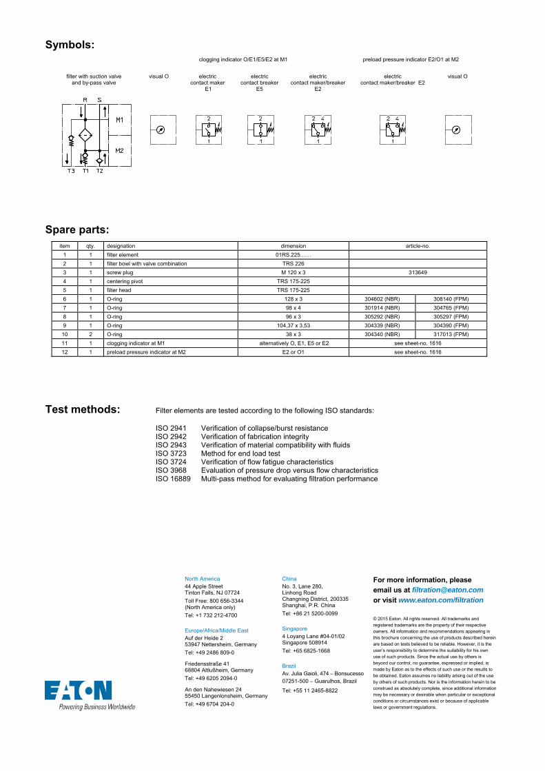
Symbols: clogging indicator O/E1/E5/E2 at M1 preload pressure indicator E2/O1 at M2
filter with suction valve and by-pass valve
visual O electric contact maker
E1
electric contact breaker
E5
electric contact maker/breaker
E2
electric contact maker/breaker E2
visual O
Spare parts: item qty. designation dimension article-no.
1 1 filter element 01RS.225……
2 1 filter bowl with valve combination TRS 226
3 1 screw plug M 120 x 3 313649
4 1 centering pivot TRS 175-225
5 1 filter head TRS 175-225
6 1 O-ring 128 x 3 304602 (NBR) 308140 (FPM)
7 1 O-ring 98 x 4 301914 (NBR) 304765 (FPM)
8 1 O-ring 96 x 3 305292 (NBR) 305297 (FPM)
9 1 O-ring 104,37 x 3,53 304339 (NBR) 304390 (FPM)
10 2 O-ring 38 x 3 304340 (NBR) 317013 (FPM)
11 1 clogging indicator at M1 alternatively O, E1, E5 or E2 see sheet-no. 1616
12 1 preload pressure indicator at M2 E2 or O1 see sheet-no. 1616
Test methods: Filter elements are tested according to the following ISO standards:
ISO 2941 Verification of collapse/burst resistance ISO 2942 Verification of fabrication integrity ISO 2943 Verification of material compatibility with fluids ISO 3723 Method for end load test ISO 3724 Verification of flow fatigue characteristics ISO 3968 Evaluation of pressure drop versus flow characteristics ISO 16889 Multi-pass method for evaluating filtration performance
North America 44 Apple Street Tinton Falls, NJ 07724
Toll Free: 800 656-3344 (North America only)
Tel: +1 732 212-4700 Europe/Africa/Middle East Auf der Heide 2 53947 Nettersheim, Germany
Tel: +49 2486 809-0
Friedensstraße 41 68804 Altlußheim, Germany
Tel: +49 6205 2094-0
An den Nahewiesen 24 55450 Langenlonsheim, Germany
Tel: +49 6704 204-0
China No. 3, Lane 280, Linhong Road Changning District, 200335 Shanghai, P.R. China
Tel: +86 21 5200-0099 Singapore 4 Loyang Lane #04-01/02 Singapore 508914
Tel: +65 6825-1668 Brazil Av. Julia Gaioli, 474 – Bonsucesso 07251-500 – Guarulhos, Brazil
Tel: +55 11 2465-8822
For more information, please email us at [email protected]
or visit www.eaton.com/filtration
© 2015 Eaton. All rights reserved. All trademarks and registered trademarks are the property of their respective owners. All information and recommendations appearing in this brochure concerning the use of products described herein are based on tests believed to be reliable. However, it is the user’s responsibility to determine the suitability for his own use of such products. Since the actual use by others is beyond our control, no guarantee, expressed or implied, is made by Eaton as to the effects of such use or the results to be obtained. Eaton assumes no liability arising out of the use by others of such products. Nor is the information herein to be construed as absolutely complete, since additional information may be necessary or desirable when particular or exceptional conditions or circumstances exist or because of applicable laws or government regulations.

Series TRS 625
145 PSI
RETURN LINE FILTER, with suction connection
Sheet No. 1066 F
EDV 09/15
Weight: approx. 13.2 lbs.
Dimensions: inches Designs and performance values are subject to change.

Return Line Filter
Series TRS 625
145 PSI
Description:
TRS series return line filters are suitable for a working pressure up to 145 PSI.
TRS series are tank-top mounted in-line filters. In addition to the return-line connection, they have a suction connection on the clean-side. This suction connection has a preload pressure (fitting pressure) of 7.25 PSI.
This combination, return-line and suction filter, is for hydraulic circuits which are equipped with a minimum 2 feed pumps (2 hydraulic circuits). The preload suction connection is for the full volume flow filtration of the pump with the smaller volume flow.
The filter element consists of star-shaped, pleated filter material, which is supported on the inside by a perforated core tube and is bonded to the end caps with a high-quality adhesive. The flow direction is from outside to inside. Filter elements are available down to 4 µm(c).
Eaton filter elements are known for high intrinsic stability and an excellent filtration capability, a high dirt-retaining capacity and a long service life.
Eaton filters can be used for petroleum-based fluids, HW emulsions, water glycols, most synthetic fluids and lubrication fluids. Consult factory for specific fluid applications.
When changing the filter element, a detachable connection between the filter head and the filter bowl prevents a flow back of dirty oil into the tank.
1. Type index:
1.1. Complete filter: (ordering example)
TRS. 625. 10VG.10.B. P. -. FS. 8. -. S2,5. Z. O. E21 2 3 4 5 6 7 8 9 10 11 12 13 14
1 series: TRS = tank-mounted return-line filter with suction connection
2 nominal size: 625
3 filter-material and filter-fineness: 80G, 40G, 25G stainless steel wire mesh 25VG, 16VG, 10VG, 6VG, 3VG microglass 10P paper
4 filter element collapse rating: 10 = p 145 PSI
5 filter element design: B = both sides open
6 sealing material: P = Nitrile (NBR) V = Viton (FPM)
7 filter element specification: - = standard VA = stainless steel
8 process connection: FS = SAE-flange 3000 PSI
9 process connection size: 8 = 2“
10 filter housing specification: - = standard
11 internal valve: S2,5 = with by-pass valve p 36 PSI
12 suction valve: Z = with suction valve
13 clogging indicator at M1: - = without O = visual, see sheet-no. 1616 E1 = pressure switch, see sheet-no. 1616 E2 = pressure switch, see sheet-no. 1616 E5 = pressure switch, see sheet-no. 1616
14 preload pressure indicator at M2: - = without E2 = pressure switch, see sheet-no. 1616
To add an indicator to your filter, use the corresponding indicator data sheet to find the indicator details and add them to the filter assembly model code.
1.2. Filter element: (ordering example)
01E. 625. 10VG. 10. B. P. - 1 2 3 4 5 6 7
1 series: 01E. = filter element according to company standard
2 nominal size: 625
3 - 7 see type index-complete filter

Technical data:
design temperature: 14 °F to +212 °F operating temperature: 14 °F to +176 °F operating medium mineral oil, other media on request max. operating pressure: 145 PSI opening pressure by-pass valve: 36 PSI opening pressure preload valve: 7.25 PSI opening pressure suction valve: .72 PSI line adapter: SAE 2” and 1 ½” housing material: Al-casting, polyamide 6 sealing material: Nitrile (NBR) or Viton (FPM), other materials on request installation position: vertical volume tank: 1.0 Gal.
Classified under the Pressure Equipment Directive 2014/68/EC for mineral oil (fluid group 2), Article 4, Para. 3. Classified under ATEX Directive 2014/34/EC according to specific application (see questionnaire sheet-no. 34279-4).
Pressure drop flow curves:
Filter calculation/sizing
The pressure drop of the assembly at a given flow rate Q is the sum of the housing ∆p and the element ∆p and is calculated as follows:
p assembly = p housing + p element p housing = (see p = f (Q) - characteristics)
p element (PSI) = .
³
For ease of calculation our Filter Selection tool is available online at www.eatonpowersource.com/calculators/filtration/
Material gradient coefficients (MSK) for filter elements
The material gradient coefficients in psi/gpm apply to mineral oil (HLP) with a density of 0.876 kg/dm³ and a kinematic viscosity of 139 SUS (30 mm²/s). The pressure drop changes proportionally to the change in kinematic viscosity and density.
TRS VG G P
3VG 6VG 10VG 16VG 25VG 25G 40G 80G 10P
625 0.696 0.483 0.309 0.269 0.184 0.0236 0.0220 0.0151 0.142
∆p = f(Q) – characteristics according to ISO 3968
The pressure drop characteristics apply to mineral oil (HLP) with a density of 0.876 kg/dm³. The pressure drop changes proportionally to the density.

Symbols:
clogging indicator O/E1/E5/E2 at M1
preload pressure indicator E2 at M2
filter with suction valve
and by-pass valve visual O electric
contact maker E1electric
contact breaker E5electric
contact maker/breaker E2 electric
contact maker/breaker E2
Spare parts: item qty. designation Abmessung article-no.
1 1 filter element 01E.625…
2 1 filter bowl with suction valve and by-pass valve TRS 625
3 1 filter cover TRS 625
4 1 filter head TRS 625
5 1 O-ring 135 x 3,5 318386 (NBR) 318387 (FPM)
6 1 O-ring 120 x 4 305300 (NBR) 307991 (FPM)
7 1 O-ring 125 x 3 306025 (NBR) 307358 (FPM)
8 1 O-ring 140 x 3 304604 (NBR) 307514 (FPM)
8 2 O-ring 63 x 3,5 311189 (NBR) 311592 (FPM)
10 1 clogging indicator at M1 alternatively O, E1, E5 or E2 see sheet-no. 1616
11 1 preload pressure indicator at M2 E2 see sheet-no. 1616
Test methods: Filter elements are tested according to the following ISO standards:
ISO 2941 Verification of collapse/burst resistance ISO 2942 Verification of fabrication integrity ISO 2943 Verification of material compatibility with fluids ISO 3723 Method for end load test ISO 3724 Verification of flow fatigue characteristics ISO 3968 Evaluation of pressure drop versus flow characteristics ISO 16889 Multi-pass method for evaluating filtration performance
North America 44 Apple Street Tinton Falls, NJ 07724
Toll Free: 800 656-3344 (North America only)
Tel: +1 732 212-4700 Europe/Africa/Middle East Auf der Heide 2 53947 Nettersheim, Germany
Tel: +49 2486 809-0
Friedensstraße 41 68804 Altlußheim, Germany
Tel: +49 6205 2094-0
An den Nahewiesen 24 55450 Langenlonsheim, Germany
Tel: +49 6704 204-0
China No. 3, Lane 280, Linhong Road Changning District, 200335 Shanghai, P.R. China
Tel: +86 21 5200-0099 Singapore 4 Loyang Lane #04-01/02 Singapore 508914
Tel: +65 6825-1668 Brazil Av. Julia Gaioli, 474 – Bonsucesso 07251-500 – Guarulhos, Brazil
Tel: +55 11 2465-8822
For more information, please email us at [email protected]
or visit www.eaton.com/filtration
© 2015 Eaton. All rights reserved. All trademarks and registered trademarks are the property of their respective owners. All information and recommendations appearing in this brochure concerning the use of products described herein are based on tests believed to be reliable. However, it is the user’s responsibility to determine the suitability for his own use of such products. Since the actual use by others is beyond our control, no guarantee, expressed or implied, is made by Eaton as to the effects of such use or the results to be obtained. Eaton assumes no liability arising out of the use by others of such products. Nor is the information herein to be construed as absolutely complete, since additional information may be necessary or desirable when particular or exceptional conditions or circumstances exist or because of applicable laws or government regulations.

Series TRW 310
145 PSI
RETURN LINE FILTER, horizontal tank mounted
Sheet No. 1068 E
EDV 09/15
Weight: approx. 6.20 lbs.
Dimensions: inches Designs and performance values are subject to change.
mounting surface surface quality flatness tolerance
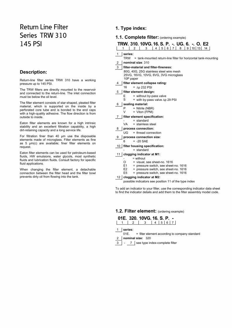
Return Line Filter
Series TRW 310
145 PSI
Description:
Return-line filter series TRW 310 have a working pressure up to 145 PSI.
The TRW filters are directly mounted to the reservoir and connected to the return-line. The inlet connection must be below the oil level.
The filter element consists of star-shaped, pleated filter material, which is supported on the inside by a perforated core tube and is bonded to the end caps with a high-quality adhesive. The flow direction is from outside to inside.
Eaton filter elements are known for a high intrinsic stability and an excellent filtration capability, a high dirt-retaining capacity and a long service life.
For filtration finer than 40 μm use the disposable elements made of microglass. Filter elements as fine as 5 μm(c) are available; finer filter elements on request.
Eaton filter elements can be used for petroleum-based fluids, HW emulsions, water glycols, most synthetic fluids and lubrication fluids. Consult factory for specific fluid applications.
When changing the filter element, a detachable connection between the filter head and the filter bowl prevents dirty oil from flowing into the tank.
1. Type index:
1.1. Complete filter: (ordering example)
TRW. 310. 10VG.16. S. P. -. UG. 6. -. O. E21 2 3 4 5 6 7 8 9 10 13 14
1 series: TRW = tank-mounted return-line filter for horizontal tank-mounting
2 nominal size: 310
3 filter-material and filter-fineness: 80G, 40G, 25G stainless steel wire mesh 25VG, 16VG, 10VG, 6VG, 3VG microglass 10P paper
4 filter element collapse rating: 16 = p 232 PSI
5 filter element design: E = without by-pass valve S = with by-pass valve p 29 PSI
6 sealing material: P = Nitrile (NBR) V = Viton (FPM)
7 filter element specification: - = standard VA = stainless steel
8 process connection: UG = thread connection
9 process connection size: 6 = -20 SAE
10 filter housing specification: - = standard
11 clogging indicator at M1: - = without O = visual, see sheet-no. 1616 E1 = pressure switch, see sheet-no. 1616 E2 = pressure switch, see sheet-no. 1616 E5 = pressure switch, see sheet-no. 1616
12 clogging indicator at M2: possible indicators see position 11 of the type index
To add an indicator to your filter, use the corresponding indicator data sheet to find the indicator details and add them to the filter assembly model code.
1.2. Filter element: (ordering example)
01E. 320. 10VG. 16. S. P. - 1 2 3 4 5 6 7
1 series: 01E. = filter element according to company standard
2 nominal size: 320
3 - 7 see type index-complete filter

Technical data:
design temperature: 14 °F to +212 °F operating temperature: 14 °F to +176 °F operating medium mineral oil, other media on request max. operating pressure: 145 PSI opening pressure by-pass valve: 29 PSI process connection: thread connection housing material: Al-cast, glass fiber reinforced polyamide sealing material: Nitrile (NBR) or Viton (FPM), other materials on request installation position: horizontal volume tank: .40 Gal.
Classified under the Pressure Equipment Directive 2014/68/EC for mineral oil (fluid group 2), Article 4, Para. 3. Classified under ATEX Directive 2014/34/EC according to specific application (see questionnaire sheet-no. 34279-4).
Pressure drop flow curves:
Filter calculation/sizing
The pressure drop of the assembly at a given flow rate Q is the sum of the housing ∆p and the element ∆p and is calculated as follows:
p assembly = p housing + p element p housing = (see p = f (Q) - characteristics)
p element (PSI) = .
³
For ease of calculation our Filter Selection tool is available online at www.eatonpowersource.com/calculators/filtration/
Material gradient coefficients (MSK) for filter elements
The material gradient coefficients in psi/gpm apply to mineral oil (HLP) with a density of 0.876 kg/dm³ and a kinematic viscosity of 139 SUS (30 mm²/s). The pressure drop changes proportionally to the change in kinematic viscosity and density.
TRW VG G P
3VG 6VG 10VG 16VG 25VG 25G 40G 80G 10P
310 1.148 0.797 0.510 0.444 0.304 0.0337 0.0314 0.0215 0.253
∆p = f(Q) – characteristics according to ISO 3968
The pressure drop characteristics apply to mineral oil (HLP) with a density of 0.876 kg/dm³. The pressure drop changes proportionally to the density.

Symbols:
without indicator with by-pass valve visual O electric contact maker
E1
electric contact breaker
E5
electric contact maker/breaker
E2
Spare parts: item qty. designation dimension article-no.
1 1 filter element 01E.320…
2 1 filter head NG 210-310 304423
3 1 filter bowl NG 310
4 1 screw plug M 90 x 2 316637
5 1 O-ring 53 x 4 309143 (NBR) 332434 (FPM)
6 1 O-ring 62 x 4 308045 (NBR) 311472 (FPM)
7 2 O-ring 44 x 6 302222 (NBR) 304384 (FPM)
8 1 O-ring 88 x 3 304417 (NBR) 310266 (FPM)
9 1 O-ring 75 x 3 302215 (NBR) 304729 (FPM)
10 1 O-ring 82 x 3 305191 (NBR) 305298 (FPM)
11 1 sheet metal screw DIN 7976-F 6,3x13 316641
12 1 clogging indicator, visual O 301721
13 1 clogging indicator, electric alternatively E1, E2 or E5 see sheet-no. 1616
Test methods: Filter elements are tested according to the following ISO standards:
ISO 2941 Verification of collapse/burst resistance ISO 2942 Verification of fabrication integrity ISO 2943 Verification of material compatibility with fluids ISO 3723 Method for end load test ISO 3724 Verification of flow fatigue characteristics ISO 3968 Evaluation of pressure drop versus flow characteristics ISO 16889 Multi-pass method for evaluating filtration performance
North America 44 Apple Street Tinton Falls, NJ 07724
Toll Free: 800 656-3344 (North America only)
Tel: +1 732 212-4700 Europe/Africa/Middle East Auf der Heide 2 53947 Nettersheim, Germany
Tel: +49 2486 809-0
Friedensstraße 41 68804 Altlußheim, Germany
Tel: +49 6205 2094-0
An den Nahewiesen 24 55450 Langenlonsheim, Germany
Tel: +49 6704 204-0
China No. 3, Lane 280, Linhong Road Changning District, 200335 Shanghai, P.R. China
Tel: +86 21 5200-0099 Singapore 4 Loyang Lane #04-01/02 Singapore 508914
Tel: +65 6825-1668 Brazil Av. Julia Gaioli, 474 – Bonsucesso 07251-500 – Guarulhos, Brazil
Tel: +55 11 2465-8822
For more information, please email us at [email protected]
or visit www.eaton.com/filtration
© 2015 Eaton. All rights reserved. All trademarks and registered trademarks are the property of their respective owners. All information and recommendations appearing in this brochure concerning the use of products described herein are based on tests believed to be reliable. However, it is the user’s responsibility to determine the suitability for his own use of such products. Since the actual use by others is beyond our control, no guarantee, expressed or implied, is made by Eaton as to the effects of such use or the results to be obtained. Eaton assumes no liability arising out of the use by others of such products. Nor is the information herein to be construed as absolutely complete, since additional information may be necessary or desirable when particular or exceptional conditions or circumstances exist or because of applicable laws or government regulations.

Series DWF 1505
232 PSI
EDV 09/15
PRESSURE FILTER, change over
Sheet No. 2227
Weight: approx. 551 lbs
Dimensions: inches Designs and performance values are subject to change.
Position I: Filter 1 in operation Position II: Filter 2 in operation
1) Connect the stand grounding tab to a suitable earth ground point.

Duplex Pressure Filter
Series DWF 1505
232 PSI
Description: Duplex filter series DWF 1505 have a working pressure up to 232 PSI. Pressure peaks can be absorbed with a sufficient safety margin.
A changeover ball valve between the two filter housings makes it possible to switch from the dirty filter side to the clean filter side without interrupting operation. The filters can be installed as a suction filter, pressure filter or return line filter.
The filter element consists of star-shaped, pleated filter material, which is supported on the inside by a perforated core tube and is bonded to the end caps with a high-quality adhesive. Additionally, the depth filter has a metal outer core to protect the filter media. The flow direction is from outside to inside.
For cleaning the mesh element or changing the glass fiber element, remove the cover and take out the element. The mesh elements are not guaranteed to maintain 100% performance after cleaning.
For filtration finer than 40 μm, use the disposable elements made of glass fiber. Filter elements as fine as 5 μm(c) are available; finer filter elements are available upon request.
Eaton filter elements are known for high intrinsic stability and an excellent filtration capability, a high dirt-retaining capacity and a long service life.
Eaton filter elements are suitable for all petroleum based fluids, HW-emulsions, most synthetic hydraulic fluids and lubrication oils.
Ship classifications available upon request.
Type index:
Complete filter: (ordering example)
DWF. 1505. 10VG. 10. E. P. -. FS. B. -. OP1 2 3 4 5 6 7 8 9 10 11
1 series: DWF = double welded filter
2 nominal size: 1505
3 filter-material and filter-fineness: stainless steel wire mesh: 80G, 40G, 25G, 10G glass fiber: 25VG, 16VG, 10VG, 6VG, 3VG glass fiber according to API: 25API, 10API
4 filter element collapse rating: 10 = p 145 PSI
5 filter element design: E = without by-pass S = with by-pass valve p 29 PSI
6 sealing material: P = Nitrile (NBR) V = Viton (FPM)
7 filter element specification: (see catalog) - = standard VA = stainless steel IS06 = see sheet-no. 31601
8 process connection: FS = flange SAE 3000 PSI
9 process connection size: B = 4“
10 filter housing specification: (see catalog) - = standard IS06 = see sheet-no. 31605
11 clogging indicator or clogging sensor: - = without AE = visual-electric, see sheet-no.1615 OP = visual, see sheet-no.1614 OE = visual-electric, see sheet-no.1614 VS5 = electronic, see sheet-no.1619
Filter element: (ordering example)
01E. 1501. 10VG. 10. E. P. - 1 2 3 4 5 6 7
1 series: 01E. = filter element according to company standard
2 nominal size : 1501
3 - 7 see type index complete filter
Accessories:
- measure- and bleeder connection, see sheet-no. 1650 - drain- and bleeder connection, see sheet-no. 1651 - shut-off valve, see sheet-no. 1655 - lifting mechanism, see sheet-no. 1661

T
Technical
design temperaoperating tempoperating medmax. operatingtest pressure: process connehousing matersealing materiainstallation posdrain- and bleemeasure connevolume tank:
Classified undeClassified unde
Pressure
Filter calcu
The pressure d
p assembly = pp housing = (se
For ease of cawww.eatonpow
Material gra
The material g139 SUS (30 m
DWF
DWF 1505
∆p = f(Q) –
The pressure dto the density.
data: ature: perature: ium
g pressure:
ection: ial: al: sition: eder connectionections:
er the Pressureer ATEX Directi
drop flow
ulation/sizin
drop of the asse
p housing + p elem
ee p = f (Q) - ch
∆
lculation our Filwersource.com/
adient coeff
radient coefficiemm²/s). The pre
3VG 6
5 0,193 0
characteris
drop characteris
ns:
Equipment Direive 2014/34/EC
w curves:
Performa
g
embly at a given
ment haracteristics)
ter Selection to/calculators/filtra
ficients (MS
ents in PSI/GPMssure drop chan
VG
6VG 10VG
0,134 0,08
stics accord
stics apply to mi
14 °F to +21214 °F to +176mineral oil, oth232 PSI 334 PSI flange SAE 30C-steel Nitrile (NBR) overtical ½ BSPP ¼ BSPP 2x 8,6 Gal.
ective 2014/68/according to sp
nce charact
n flow rate Q is t
ol is available oation/
SK) for filter
M apply to minernges proportion
G
G 16VG
86 0,075
ing to ISO 3
ineral oil (HLP)
°F °F
her media on re
000 PSI
or Viton (FPM),
EC for mineral opecific applicatio
teristics of D
the sum of the h
1000
online at
elements
ral oil (HLP) witnally to the chan
25VG 1
0,051 0,0
3968
with a density o
equest
other materials
oil (fluid group 2on (see question
DWF 1505 (D
housing ∆p and
h a density of 0nge in kinematic
10G 25G
0071 0,005
of 0,876 kg/dm³
on request
2), Article 4, Parnnaire sheet-no
Data sheet 2
the element ∆p
0
,876 kg/dm³ anc viscosity and d
G
G 40G
53 0,0049
. The pressure d
ra. 3. o. 34279-4).
2227)
p and is calculat
0,876 ³
d a kinematic vidensity.
80G 1
0,0034 0
drop changes p
ted as follows:
iscosity of
API
10API 25A
0,048 0,02
proportionally
PI
22

Symbols: without indicator
with
electric indicator
AE 30 and AE 40
with visual- electric
indicator AE 50 and AE 62
with visual-electric
indicator AE 70 and AE 80
with visual
indicator OP
with visual-electric
indicator OE
with electronic
sensor VS5
Spare parts: item qty. designation dimension Article-no.
1 2 filter element 01E.1501… 2 2 O-ring 93 x 5 307588 (NBR) 307589 (FPM) 3 2 O-ring 250 x 5 xxxxxx (NBR) xxxxxx (FPM) 4 4 gasket kit of change over UKK DN100 (4“) 322721 (NBR) 322722 (FPM) 5 6 screw plug ½ BSPP 304678 6 1 clogging indicator, visual-electric AE see sheet-no.1615 7 1 clogging indicator, visual OP see sheet-no 1614 8 1 clogging indicator, visual-electric OE see sheet-no 1614 9 1 clogging sensor, electronic VS5 see sheet-no 1619 10 1 O-ring 22 x 2 304708 (NBR) 304721 (FPM) 11 1 O-ring 14 x 2 304342 (NBR) 304722 (FPM)
Test methods: Filter elements are tested according to the following ISO standards:
ISO 2941 Verification of collapse/burst resistance ISO 2942 Verification of fabrication integrity ISO 2943 Verification of material compatibility with fluids ISO 3723 Method for end load test ISO 3724 Verification of flow fatigue characteristics ISO 3968 Evaluation of pressure drop versus flow characteristics ISO 16889 Multi-pass method for evaluating filtration performance
North America 44 Apple Street Tinton Falls, NJ 07724
Toll Free: 800 656-3344 (North America only)
Tel: +1 732 212-4700 Europe/Africa/Middle East Auf der Heide 2 53947 Nettersheim, Germany
Tel: +49 2486 809-0
Friedensstraße 41 68804 Altlußheim, Germany
Tel: +49 6205 2094-0
An den Nahewiesen 24 55450 Langenlonsheim, Germany
Tel: +49 6704 204-0
China No. 3, Lane 280, Linhong Road Changning District, 200335 Shanghai, P.R. China
Tel: +86 21 5200-0099 Singapore 4 Loyang Lane #04-01/02 Singapore 508914
Tel: +65 6825-1668 Brazil Av. Julia Gaioli, 474 – Bonsucesso 07251-500 – Guarulhos, Brazil
Tel: +55 11 2465-8822
For more information, please email us at [email protected]
or visit www.eaton.com/filtration
© 2015 Eaton. All rights reserved. All trademarks and registered trademarks are the property of their respective owners. All information and recommendations appearing in
this brochure concerning the use of products described herein are based on tests believed to be reliable. However, it is the user’s responsibility to determine the suitability for his own use of such products. Since the actual use by others is beyond our control, no guarantee, expressed or implied, is
made by Eaton as to the effects of such use or the results to be obtained. Eaton assumes no liability arising out of the use by others of such products. Nor is the information herein to be construed as absolutely complete, since additional information may be necessary or desirable when particular or exceptional
conditions or circumstances exist or because of applicable laws or government regulations.

Series DWF 3005
232 PSI
EDV 07/15
PRESSURE FILTER, change over
Sheet No. 2228
Position I: Filter 1 in operation Position II: Filter 2 in operation
1) Connect the stand grounding tab to a suitable earth ground point.
Weight: approx. 683 lbs
Dimensions: inches Designs and performance values are subject to change.

Duplex Pressure Filter
Series DWF 3005
232 PSI
Description: Duplex filter series DWF 3005 have a working pressure up to 232 PSI. Pressure peaks can be absorbed with a sufficient safety margin.
A changeover ball valve between the two filter housings makes it possible to switch from the dirty filter side to the clean filter side without interrupting operation. The filters can be installed as a suction filter, pressure filter or return line filter.
The filter element consists of star-shaped, pleated filter material, which is supported on the inside by a perforated core tube and is bonded to the end caps with a high-quality adhesive. Additionally, the depth filter has a metal outer core to protect the filter media. The flow direction is from outside to inside.
For cleaning the mesh element or changing the glass fiber element, remove the cover and take out the element. The mesh elements are not guaranteed to maintain 100% performance after cleaning.
For filtration finer than 40 μm, use the disposable elements made of glass fiber. Filter elements as fine as 5 μm(c) are available; finer filter elements are available upon request.
Eaton filter elements are known for high intrinsic stability and an excellent filtration capability, a high dirt-retaining capacity and a long service life.
Eaton filter elements are suitable for all petroleum based fluids, HW-emulsions, most synthetic hydraulic fluids and lubrication oils.
Ship classifications available upon request.
Type index:
Complete filter: (ordering example)
DWF. 3005. 10VG. 10. E. P. -. FS. C. -. OP1 2 3 4 5 6 7 8 9 10 11
1 series: DWF = double welded filter
2 nominal size: 3005
3 filter-material and filter-fineness: stainless steel wire mesh: 80G, 40G, 25G, 10G glass fiber: 25VG, 16VG, 10VG, 6VG, 3VG glass fiber according to API: 25API, 10API
4 filter element collapse rating: 10 = p 145 PSI
5 filter element design: E = without by-pass S = with by-pass valve p 29 PSI
6 sealing material: P = Nitrile (NBR) V = Viton (FPM)
7 filter element specification: (see catalog) - = standard VA = stainless steel IS06 = see sheet-no. 31601
8 process connection: FS = flange SAE 3000 PSI
9 process connection size: C = 5“
10 filter housing specification: (see catalog) - = standard IS06 = see sheet-no. 31605
11 clogging indicator or clogging sensor: - = without AE = visual-electric, see sheet-no.1615 OP = visual, see sheet-no.1614 OE = visual-electric, see sheet-no.1614 VS5 = electronic, see sheet-no.1619
Filter element: (ordering example)
01E. 1501. 10VG. 10. E. P. - 1 2 3 4 5 6 7
1 series: 01E. = filter element according to company standard
2 Nominal size: 1501
3 - 7 see type index complete filter
Accessories:
- measure- and bleeder connection, see sheet-no. 1650 - drain- and bleeder connection, see sheet-no. 1651 - shut-off valve, see sheet-no. 1655 - lifting mechanism, see sheet-no. 1661

Technica
design temperaoperating tempoperating medmax. operatingtest pressure: process connehousing materhousing matersealing materiainstallation posdrain- and bleemeasure connevolume tank:
Classified undeClassified unde
Pressure
Filter calcu
The pressure d
p assembly = pp housing = (se
For ease of cawww.eatonpow
Material gra
The material g139 SUS (30 m
DWF
DWF 3005
∆p = f(Q) –
The pressure dto the density.
al data: ature: perature: ium
g pressure:
ection: ial: ial change overal: sition: eder connectionections:
er the Pressureer ATEX Directi
drop flow
ulation/sizin
drop of the asse
p housing + p elem
ee p = f (Q) - ch
∆
lculation our Filwersource.com/
adient coeff
radient coefficiemm²/s). The pre
3VG 6
5 0,096 0
characteris
drop characteris
r:
ns:
Equipment Direive 2014/34/EC
w curves:
Performa
g
embly at a given
ment haracteristics)
ter Selection to/calculators/filtra
ficients (MS
ents in PSI/GPMssure drop chan
VG
6VG 10VG
0,067 0,04
stics accord
stics apply to mi
14 °F to +21214 °F to +176mineral oil, oth232 PSI 334 PSI flange SAE 30C-steel EN-GJS-400-1Nitrile (NBR) overtical ½ BSPP ¼ BSPP 2x 18,2 Gal.
ective 2014/68/according to sp
nce charact
n flow rate Q is t
ol is available oation/
SK) for filter
M apply to minernges proportion
G
G 16VG
43 0,037
ing to ISO 3
ineral oil (HLP)
°F °F
her media on re
000 PSI
18-LT or Viton (FPM),
EC for mineral opecific applicatio
teristics of D
the sum of the h
1000
online at
elements
ral oil (HLP) witnally to the chan
25VG 1
0,025 0,0
3968
with a density o
equest
other materials
oil (fluid group 2on (see question
DWF 3005 (D
housing ∆p and
h a density of 0nge in kinematic
10G 25G
0035 0,002
of 0,876 kg/dm³
on request
2), Article 4, Parnnaire sheet-no
Data sheet 2
the element ∆p
0
,876 kg/dm³ anc viscosity and d
G
G 40G
26 0,0025
. The pressure d
ra. 3. o. 34279-4).
2228)
p and is calculat
0,876 ³
d a kinematic vidensity.
80G 1
0,0017 0
drop changes p
ted as follows:
iscosity of
API
10API 25A
0,024 0,01
proportionally
PI
11

Symbols: without indicator
with
electric indicator
AE 30 and AE 40
with visual- electric
indicator AE 50 and AE 62
with visual-electric
indicator AE 70 and AE 80
with visual
indicator OP
with visual-electric
indicator OE
with electronic
sensor VS5
Spare parts: item qty. designation dimension Article-no.
1 4 filter element 01E.1501… 2 4 O-ring 93 x 5 307588 (NBR) 307589 (FPM) 3 2 O-ring 330 x 5 xxxxxx (NBR) 310275 (FPM) 4 4 gasket kit of change over UKK DN125 (5“) 322726 (NBR) 322727 (FPM) 5 6 screw plug ½ BSPP 304678 6 1 clogging indicator, visual-electric AE see sheet-no.1615 7 1 clogging indicator, visual OP see sheet-no 1614 8 1 clogging indicator, visual-electric OE see sheet-no 1614 9 1 clogging sensor, electronic VS5 see sheet-no 1619 10 1 O-ring 22 x 2 304708 (NBR) 304721 (FPM) 11 1 O-ring 14 x 2 304342 (NBR) 304722 (FPM)
Test methods: Filter elements are tested according to the following ISO standards:
ISO 2941 Verification of collapse/burst resistance ISO 2942 Verification of fabrication integrity ISO 2943 Verification of material compatibility with fluids ISO 3723 Method for end load test ISO 3724 Verification of flow fatigue characteristics ISO 3968 Evaluation of pressure drop versus flow characteristics ISO 16889 Multi-pass method for evaluating filtration performance
North America 44 Apple Street Tinton Falls, NJ 07724
Toll Free: 800 656-3344 (North America only)
Tel: +1 732 212-4700 Europe/Africa/Middle East Auf der Heide 2 53947 Nettersheim, Germany
Tel: +49 2486 809-0
Friedensstraße 41 68804 Altlußheim, Germany
Tel: +49 6205 2094-0
An den Nahewiesen 24 55450 Langenlonsheim, Germany
Tel: +49 6704 204-0
China No. 3, Lane 280, Linhong Road Changning District, 200335 Shanghai, P.R. China
Tel: +86 21 5200-0099 Singapore 4 Loyang Lane #04-01/02 Singapore 508914
Tel: +65 6825-1668 Brazil Av. Julia Gaioli, 474 – Bonsucesso 07251-500 – Guarulhos, Brazil
Tel: +55 11 2465-8822
For more information, please email us at [email protected]
or visit www.eaton.com/filtration
© 2015 Eaton. All rights reserved. All trademarks and registered trademarks are the property of their respective owners. All information and recommendations appearing in this brochure concerning the use of products described herein are based on tests believed to be reliable. However, it is the
user’s responsibility to determine the suitability for his own use of such products. Since the actual use by others is beyond our control, no guarantee, expressed or implied, is made by Eaton as to the effects of such use or the results to be obtained. Eaton assumes no liability arising out of the use
by others of such products. Nor is the information herein to be construed as absolutely complete, since additional information may be necessary or desirable when particular or exceptional conditions or circumstances exist or because of applicable laws or government regulations.

Series DWF 4505
232 PSI
EDV 07/15
PRESSURE FILTER, changeover
Sheet No. 2229
Position I: Filter 1 in operation Position II: Filter 2 in operation
1) Connect the stand grounding tab to a suitable earth ground point.
Weight: approx. 1323 lbs.
Dimensions: inches Designs and performance values are subject to change.
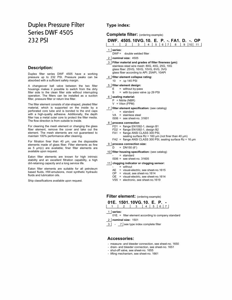
Duplex Pressure Filter
Series DWF 4505
232 PSI
Description: Duplex filter series DWF 4505 have a working pressure up to 232 PSI. Pressure peaks can be absorbed with a sufficient safety margin.
A changeover ball valve between the two filter housings makes it possible to switch from the dirty filter side to the clean filter side without interrupting operation. The filters can be installed as a suction filter, pressure filter or return line filter.
The filter element consists of star-shaped, pleated filter material, which is supported on the inside by a perforated core tube and is bonded to the end caps with a high-quality adhesive. Additionally, the depth filter has a metal outer core to protect the filter media. The flow direction is from outside to inside.
For cleaning the mesh element or changing the glass fiber element, remove the cover and take out the element. The mesh elements are not guaranteed to maintain 100% performance after cleaning.
For filtration finer than 40 μm, use the disposable elements made of glass fiber. Filter elements as fine as 5 μm(c) are available; finer filter elements are available upon request.
Eaton filter elements are known for high intrinsic stability and an excellent filtration capability, a high dirt-retaining capacity and a long service life.
Eaton filter elements are suitable for all petroleum based fluids, HW-emulsions, most synthetic hydraulic fluids and lubrication oils.
Ship classifications available upon request.
Type index:
Complete filter: (ordering example)
DWF. 4505. 10VG. 10. E. P. -. FA1. D. -. OP1 2 3 4 5 6 7 8 9 10 11
1 series: DWF = double welded filter
2 nominal size: 4505
3 Filter material and grades of filter fineness (µm): stainless steel wire mesh: 80G, 40G, 25G, 10G glass fiber: 25VG, 16VG, 10VG, 6VG, 3VG glass fiber according to API: 25API, 10API
4 filter element collapse rating: 10 = p 145 PSI
5 filter element design: E = without by-pass S = with by-pass valve p 29 PSI
6 sealing material: P = Nitrile (NBR) V = Viton (FPM)
7 filter element specification: (see catalog) - = standard VA = stainless steel IS06 = see sheet-no. 31601
8 process connection FD1 = flange EN1092-1, design B1 FD2 = flange EN1092-1, design B2 FA1 = flange ANSI CLASS 300 PSI,
sealing surface Rz = 160 μm (not finer than 40 μm) FA2 = flange ANSI CLASS 300 PSI, sealing surface Rz = 16 μm
9 process connection size: D = DN150 (6“)
10 filter housing specification: (see catalog) - = standard IS06 = see sheet-no. 31605
11 clogging indicator or clogging sensor: - = without AE = visual-electric, see sheet-no.1615 OP = visual, see sheet-no.1614 OE = visual-electric, see sheet-no.1614 VS5 = electronic, see sheet-no.1619
Filter element: (ordering example)
01E. 1501. 10VG. 10. E. P. - 1 2 3 4 5 6 7
1 series: 01E. = filter element according to company standard
2 nominal size: 1501
3 - 7 see type index complete filter
Accessories:
- measure- and bleeder connection, see sheet-no. 1650 - drain- and bleeder connection, see sheet-no. 1651 - shut-off valve, see sheet-no. 1655 - lifting mechanism, see sheet-no. 1661

Technica
design temperaoperating tempoperating medmax. operatingtest pressure: process connehousing materhousing matersealing materiainstallation posdrain- and bleemeasure connevolume tank: Classified undeClassified unde
Pressure
Filter calcu
The pressure d
p assembly = pp housing = (se
For ease of cawww.eatonpow
Material gra
The material g139 SUS (30 m
DWF
DWF 4505
∆p = f(Q) –
The pressure dto the density.
al data: ature: perature: ium
g pressure:
ection: ial: ial change overal: sition: eder connectionections:
er the Pressureer ATEX Directi
drop flow
ulation/sizin
drop of the asse
p housing + p elem
ee p = f (Q) - ch
∆
lculation, our Fiwersource.com/
adient coeff
radient coefficiemm²/s). The pre
3VG 6
5 0.064 0
characteris
drop characteris
r:
ns:
Equipment Direive 2014/34/EC
w curves:
Performa
g
embly at a given
ment haracteristics)
ilter Selection to/calculators/filtra
ficients (MS
ents in PSI/GPMssure drop chan
VG
6VG 10VG
0.045 0.02
stics accord
stics apply to mi
14 °F to +21214 °F to +176mineral oil, oth232 PSI 334 PSI flange EN1092C-steel EN-GJS-400-1Nitrile (NBR) overtical ½ BSPP ¼ BSPP 2x 23,8 Gal.
ective 2014/68/according to sp
nce charact
n flow rate Q is t
ool is available oation/
SK) for filter
M apply to minernges proportion
G
G 16VG
29 0.025
ing to ISO 3
ineral oil (HLP)
°F °F
her media on re
2-1, 232 PSI or
18-LT or Viton (FPM),
EC for mineral opecific applicatio
teristics of D
the sum of the h
1000
online at:
elements
ral oil (HLP) witnally to the chan
25VG 1
0.017 0.0
3968
with a density o
equest
r flange ANSI B
other materials
oil (fluid group 2on (see question
DWF 4505 (D
housing ∆p and
h a density of 0nge in kinematic
10G 25G
0024 0.001
of 0,876 kg/dm³
16.5 CLASS 30
on request
2), Article 4, Parnnaire sheet-no
Data sheet 2
the element ∆p
0
,876 kg/dm³ anc viscosity and d
G
G 40G
18 0.0016
. The pressure d
00 PSI
ra. 3. o. 34279-4).
2229)
p and is calculat
0,876 ³
d a kinematic vidensity.
80G 1
0.0011 0
drop changes p
ted as follows:
iscosity of
API
10API 25A
0.016 0.00
proportionally
PI
07

Symbols: without indicator
with
electric indicator
AE 30 and AE 40
with visual- electric
indicator AE 50 and AE 62
with visual-electric
indicator AE 70 and AE 80
with visual
indicator OP
with visual-electric
indicator OE
with electronic
sensor VS5
Spare parts: item qty. designation dimension Article-no.
1 6 filter element 01E.1501… 2 6 O-ring 93 x 5 307588 (NBR) 307589 (FPM) 3 2 O-ring 372 x 5 347195 (NBR) xxxxxx (FPM) 4 4 gasket kit of change over UKK DN150 (6“) 319929 (NBR) 322725 (FPM) 5 6 screw plug ½ BSPP 304678 6 1 clogging indicator, visual-electric AE see sheet-no.1615 7 1 clogging indicator, visual OP see sheet-no 1614 8 1 clogging indicator, visual-electric OE see sheet-no 1614 9 1 clogging sensor, electronic VS5 see sheet-no 1619 10 1 O-ring 22 x 2 304708 (NBR) 304721 (FPM) 11 1 O-ring 14 x 2 304342 (NBR) 304722 (FPM)
Test methods: Filter elements are tested according to the following ISO standards:
ISO 2941 Verification of collapse/burst resistance ISO 2942 Verification of fabrication integrity ISO 2943 Verification of material compatibility with fluids ISO 3723 Method for end load test ISO 3724 Verification of flow fatigue characteristics ISO 3968 Evaluation of pressure drop versus flow characteristics ISO 16889 Multi-pass method for evaluating filtration performance
North America 44 Apple Street Tinton Falls, NJ 07724
Toll Free: 800 656-3344 (North America only)
Tel: +1 732 212-4700 Europe/Africa/Middle East Auf der Heide 2 53947 Nettersheim, Germany
Tel: +49 2486 809-0
Friedensstraße 41 68804 Altlußheim, Germany
Tel: +49 6205 2094-0
An den Nahewiesen 24 55450 Langenlonsheim, Germany
Tel: +49 6704 204-0
China No. 3, Lane 280, Linhong Road Changning District, 200335 Shanghai, P.R. China
Tel: +86 21 5200-0099 Singapore 4 Loyang Lane #04-01/02 Singapore 508914
Tel: +65 6825-1668 Brazil Av. Julia Gaioli, 474 – Bonsucesso 07251-500 – Guarulhos, Brazil
Tel: +55 11 2465-8822
For more information, please email us at [email protected]
or visit www.eaton.com/filtration
© 2015 Eaton. All rights reserved. All trademarks and registered trademarks are the property of their respective
owners. All information and recommendations appearing in this brochure concerning the use of products described herein are based on tests believed to be reliable. However, it is the user’s responsibility to determine the suitability for his own use of such products. Since the actual use by others is
beyond our control, no guarantee, expressed or implied, is made by Eaton as to the effects of such use or the results to be obtained. Eaton assumes no liability arising out of the use by others of such products. Nor is the information herein to be construed as absolutely complete, since additional information
may be necessary or desirable when particular or exceptional conditions or circumstances exist or because of applicable laws or government regulations.

Series DWF 6005
232 PSI
EDV 09/15
PRESSURE FILTER, change over
Sheet No. 2230
Position I: Filter 1 in operation Position II: Filter 2 in operation
1) Connect the stand grounding tab to a suitable earth ground point.
Weight: approx. 1504 lbs.
Dimensions: inches Designs and performance values are subject to change.

Duplex Pressure Filter
Series DWF 6005
232 PSI
Description: Duplex filter series DWF 6005 have a working pressure up to 232 PSI. Pressure peaks can be absorbed with a sufficient safety margin.
A change over ball valve between the two filter housings makes it possible to switch from the dirty filter-side to the clean filter-side without interrupting operation. The filters can be installed as a suction filter, pressure filter or return-line filter.
The filter element consists of star-shaped, pleated filter material, which is supported on the inside by a perforated core tube and is bonded to the end caps with a high-quality adhesive. Additionally, the depth filter has a metal outer core to protect the filter media. The flow direction is from outside to inside.
For cleaning the mesh element or changing the glass fiber element, remove the cover and take out the element. The mesh elements are not guaranteed to maintain 100% performance after cleaning.
For filtration finer than 40 μm, use the disposable elements made of glass fiber. Filter elements as fine as 5 μm(c) are available; finer filter elements are available upon request.
Eaton filter elements are known for high intrinsic stability and an excellent filtration capability, a high dirt-retaining capacity and a long service life.
Eaton filter elements are suitable for all petroleum based fluids, HW-emulsions, most synthetic hydraulic fluids and lubrication oils.
Ship classifications available upon request.
Type index:
Complete filter: (ordering example)
DWF. 6005. 10VG. 10. E. P. -. FA1. E. -. OP1 2 3 4 5 6 7 8 9 10 11
1 series: DWF = double welded filter
2 nominal size: 6005
3 filter-material and filter-fineness: stainless steel: 80G, 40G, 25G, 10G glass fiber: 25VG, 16VG, 10VG, 6VG, 3VG glass fiber according to API: 25API, 10API
4 filter element collapse rating: 10 = p 145 PSI
5 filter element design: E = without by-pass S = with by-pass valve p 29 PSI
6 sealing material: P = Nitrile (NBR) V = Viton (FPM)
7 filter element specification: (see catalog) - = standard VA = stainless steel IS06 = see sheet-no. 31601
8 process connection: FD1 = flange EN1092-1, design B1 FD2 = flange EN1092-1, design B2 FA1 = flange ANSI CLASS 300 PSI,
sealing surface Rz = 160 μm (not finer than 40 μm) FA2 = flange ANSI CLASS 300 PSI, sealing surface Rz = 16 μm
9 process connection size: E = DN200 (8”)
10 filter housing specification: (see catalog) - = standard IS06 = see sheet-no. 31605
11 clogging indicator or clogging sensor: - = without AE = visual-electric, see sheet-no.1615 OP = visual, see sheet-no.1614 OE = visual-electric, see sheet-no.1614 VS5 = electronic, see sheet-no.1619
Filter element: (ordering example)
01E. 1501. 10VG. 10. E. P. - 1 2 3 4 5 6 7
1 series: 01E. = filter element according to company standard
2 nominal size: 1501
3 - 7 see type index complete filter
Accessories:
- measure- and bleeder connection, see sheet-no. 1650 - drain- and bleeder connection, see sheet-no. 1651 - shut-off valve, see sheet-no. 1655 - lifting mechanism, see sheet-no. 1661

Technica
design temperaoperating tempoperating medmax. operatingtest pressure: process connehousing materhousing matersealing materiainstallation posdrain- and bleemeasure connevolume tank:
Classified undeClassified unde
Pressure
Filter calcu
The pressure d
p assembly = pp housing = (se
For ease of cawww.eatonpow
Material gra
The material g139 SUS (30 m
DWF
DWF 6005
∆p = f(Q) –
The pressure dto the density.
al data: ature: perature: ium
g pressure:
ection: ial: ial change overal: sition: eder connectionections:
er the Pressureer ATEX Directi
drop flow
ulation/sizin
drop of the asse
p housing + p elem
ee p = f (Q) - ch
∆
lculation our Filwersource.com/
adient coeff
radient coefficiemm²/s). The pre
3VG 6
5 0,048 0
characteris
drop characteris
r:
ns:
Equipment Direive 2014/34/EC
w curves:
Performa
g
embly at a given
ment haracteristics)
ter Selection to/calculators/filtra
ficients (MS
ents in PSI/GPMssure drop chan
VG
6VG 10VG
0,033 0,02
stics accord
stics apply to mi
14 °F to +21214 °F to +176mineral oil, oth232 PSI 334 PSI flange EN1092C-steel EN-GJS-400-1Nitrile (NBR) overtical ½ BSPP ¼ BSPP 2x 31,2 Gal.
ective 2014/68/according to sp
nce charact
n flow rate Q is t
ol is available oation/
SK) for filter
M apply to minernges proportion
G
G 16VG
21 0,019
ing to ISO 3
ineral oil (HLP)
°F °F
her media on re
2-1, 232 psi or f
18-LT or Viton (FPM),
EC for mineral opecific applicatio
teristics of D
the sum of the h
1000
online at
elements
ral oil (HLP) witnally to the chan
25VG 1
0,013 0,0
3968
with a density o
equest
flange ANSI B16
other materials
oil (fluid group 2on (see question
DWF 6005 (D
housing ∆p and
h a density of 0nge in kinematic
10G 25G
0018 0,001
of 0,876 kg/dm³
6.5 CLASS 300
on request
2), Article 4, Parnnaire sheet-no
Data sheet 2
the element ∆p
0
,876 kg/dm³ anc viscosity and d
G
G 40G
13 0,0012
. The pressure d
0 PSI
ra. 3. o. 34279-4).
2230)
p and is calculat
0,876 ³
d a kinematic vidensity.
80G 1
0,0008 0
drop changes p
ted as follows:
iscosity of
API
10API 25A
0,012 0,00
proportionally
PI
05

Symbols: without indicator
with
electric indicator
AE 30 and AE 40
with visual- electric
indicator AE 50 and AE 62
with visual-electric
indicator AE 70 and AE 80
with visu
indicator OP
with visual-electric
indicator OE
with electronical
sensor VS5
Spare parts: item qty. designation dimension Article-no.
1 8 filter element 01E.1501… 2 8 O-ring 93 x 5 307588 (NBR) 307589 (FPM) 3 2 O-ring 429 x 6 308659 (NBR) 310273 (FPM) 4 4 gasket kit of change over UKK DN200 (8“) 322723 (NBR) 322724 (FPM) 5 6 screw plug ½ BSPP 304678 6 1 clogging indicator, visual-electric AE see sheet-no.1615 7 1 clogging indicator, visual OP see sheet-no 1614 8 1 clogging indicator, visual-electric OE see sheet-no 1614 9 1 clogging sensor, electronic VS5 see sheet-no 1619 10 1 O-ring 22 x 2 304708 (NBR) 304721 (FPM) 11 1 O-ring 14 x 2 304342 (NBR) 304722 (FPM)
Test methods: Filter elements are tested according to the following ISO standards:
ISO 2941 Verification of collapse/burst resistance ISO 2942 Verification of fabrication integrity ISO 2943 Verification of material compatibility with fluids ISO 3723 Method for end load test ISO 3724 Verification of flow fatigue characteristics ISO 3968 Evaluation of pressure drop versus flow characteristics ISO 16889 Multi-pass method for evaluating filtration performance
North America 44 Apple Street Tinton Falls, NJ 07724
Toll Free: 800 656-3344 (North America only)
Tel: +1 732 212-4700 Europe/Africa/Middle East Auf der Heide 2 53947 Nettersheim, Germany
Tel: +49 2486 809-0
Friedensstraße 41 68804 Altlußheim, Germany
Tel: +49 6205 2094-0
An den Nahewiesen 24 55450 Langenlonsheim, Germany
Tel: +49 6704 204-0
China No. 3, Lane 280, Linhong Road Changning District, 200335 Shanghai, P.R. China
Tel: +86 21 5200-0099 Singapore 4 Loyang Lane #04-01/02 Singapore 508914
Tel: +65 6825-1668 Brazil Av. Julia Gaioli, 474 – Bonsucesso 07251-500 – Guarulhos, Brazil
Tel: +55 11 2465-8822
For more information, please email us at [email protected]
or visit www.eaton.com/filtration
© 2015 Eaton. All rights reserved. All trademarks and registered trademarks are the property of their respective owners. All information and recommendations appearing in
this brochure concerning the use of products described herein are based on tests believed to be reliable. However, it is the user’s responsibility to determine the suitability for his own use of such products. Since the actual use by others is beyond our control, no guarantee, expressed or implied, is
made by Eaton as to the effects of such use or the results to be obtained. Eaton assumes no liability arising out of the use by others of such products. Nor is the information herein to be construed as absolutely complete, since additional information may be necessary or desirable when particular or exceptional
conditions or circumstances exist or because of applicable laws or government regulations.

Series DWF 1505
232 PSI
PRESSURE FILTER, changeover according to ASME
Sheet No. 2231
Weight: approx.: 714 lbs.
Dimensions: inches
Designs and performance values are subject to change.
EDV 04/16
Switch lever standard in the front.
2) On request: The switch lever can be moved to backside of the changeover valve, opposite to the inlet and outlet.
Please specify this configuration on the order.
Position I: Filter 1 in operation Position II: Filter 2 in operation
1) Connect the stand grounding tab to a suitable earth ground point.

Duplex Pressure Filter
Series DWF 1505
232 PSI
Description: Duplex filter series DWF 1505 have a working pressure up to 232 PSI. Pressure peaks can be absorbed with a sufficient safety margin.
A changeover ball valve between the two filter housings makes it possible to switch from the dirty filter side to the clean filter side without interrupting operation. The filters can be installed as a suction filter, pressure filter or return line filter.
The filter element consists of star-shaped, pleated filter material, which is supported on the inside by a perforated core tube and is bonded to the end caps with a high-quality adhesive. Additionally, the depth filter has a metal outer core to protect the filter media. The flow direction is from outside to inside.
For cleaning the stainless steel mesh element or changing the glass fiber element, remove the cover and take out the element. The mesh elements are not guaranteed to maintain 100% performance after cleaning.
For filtration finer than 25 μm, use the disposable elements made of microglass. Filter elements as fine as 3 μm are available; finer filter elements are available upon request.
Eaton filter elements are known for high intrinsic stability and an excellent filtration capability, a high dirt-retaining capacity and a long service life.
Eaton filter elements are suitable for all petroleum based fluids, HW-emulsions, most synthetic hydraulic fluids and lubrication oils.
Ship classifications available upon request.
Type index:
Complete filter: (ordering example)
DWF. 1505. 10VG. 10. E. P. -. FS. B. -. IS21.1 2 3 4 5 6 7 8 9 10 11
KH. OE12 13
1 series: DWF = double welded filter, according to ASME-code
2 nominal size: 1505
3 filter material: 80G, 40G, 25G, 10G stainless steel wire mesh 25VG, 16VG, 10VG, 6VG, 3VG microglass 25API, 10API microglass according to API
4 filter element collapse rating: 10 = p 145 PSI
5 filter element design: E = without by-pass S = with by-pass valve p 29 PSI
6 sealing material: P = Nitrile (NBR) V = Viton (FPM)
7 filter element specification: - = standard VA = stainless steel IS06 = for HFC application, see sheet-no. 31601
8 process connection: FS = SAE-flange 3000 PSI FA11 = flange ANSI CLASS 150 PSI,
sealing surface Rz = 160 μm (not finer than 40 μm) (only with connection 5”)
FA12 = flange ANSI CLASS 150 PSI, sealing surface Rz = 16 μm (only with connection 5”)
9 process connection size: B = 4“ (standard) C = 5“
10 filter housing specification: - = standard IS12 = internal parts of change over armature stainless steel,
see sheet-no. 41028
11 specification pressure vessel: IS21 = ASME VIII Div.1 with U-stamp, see sheet-no. 43415
12 shut-off : - = without KH = with shut-off ball valve
13 clogging indicator or clogging sensor: - = without AE = visual-electrical, see sheet-no. 1609 OP = visual, see sheet-no. 1614 OE = visual-electrical, see sheet-no. 1614 VS5 = sensor, see sheet-no. 1641
To add an indicator/sensor to your filter, use the corresponding indicator data sheet to find the indicator details and add them to the filter assembly model code.
Filter element: (ordering example)
01E. 1501.10VG. 10. E. P. - 1 2 3 4 5 6 7
1 series: 01E = filter element according to company standard
2 nominal size: 1501
3 - 7 see type index-complete filter
Accessories: - drain- and bleeder connection, see sheet-no. 1651 - lifting mechanism, see sheet-no. 1662

Technical data:
design temperature: 14 °F to +212 °F operating temperature: 14 °F to +176 °F operating medium mineral oil, other media on request max. operating pressure: 232 PSI test pressure acc. to ASME VIII Div. 1: 1,3 x operating pressure = 302 PSI test pressure acc. to API 614, Chapter 1: 1,5 x operating pressure = 348 PSI standard process connection: SAE-flange 3000 PSI housing material: carbon steel (ASTM) housing material change over 4”: carbon steel housing material change over 5”: EN-GJS-400-18-LT sealing material: Nitrile (NBR) or Viton (FPM), other materials on request installation position: vertical drain- and bleeder connections: NPT ½” measure connections: BSPP ¼” operating pressure adapter flanges: according to B16.5 CLASS 150 PSI Classified under the Pressure Equipment Directive 2014/68/EC for mineral oil (fluid group 2), Article 4, Para. 3. Classified under ATEX Directive 2014/34/EC according to specific application (see questionnaire sheet-no. 34279-4).
Pressure drop flow curves:
Filter calculation/sizing
The pressure drop of the assembly at a given flow rate Q is the sum of the housing ∆p and the element ∆p and is calculated as follows:
p assembly = p housing + p element p housing = (see p = f (Q) - characteristics)
For ease of calculation, our Filter Selection tool is available online at: www.eatonpowersource.com/calculators/filtration/
Material gradient coefficients (MSK) for filter elements
The material gradient coefficients in PSI/GPM apply to mineral oil (HLP) with a density of 0.876 kg/dm³ and a kinematic viscosity of 139 SUS (30 mm²/s). The pressure drop changes proportionally to the change in kinematic viscosity and density.
DWF VG G API
3VG 6VG 10VG 16VG 25VG 10G 25G 40G 80G 10 API 25 API
1505 0.160 0.111 0.071 0.062 0.042 0.0058 0.0043 0.0040 0.0027 0.039 0.018
∆p = f(Q) – characteristics according to ISO 3968
The pressure drop characteristics apply to mineral oil (HLP) with a density of 0,876 kg/dm³. The pressure drop changes proportionally to the density. The flow curve for 5” available on request.

Symbols: without indicator with
shut-off ball valve with electric
indicator AE 30 and AE 40
with visual-electric indicator
AE 50 and AE 62
with visual-electric indicator
AE 70 and AE 80
with visual indicator
OP
with visual-electric indicator
OE
with electronic sensor
VS5
Spare parts: item qty. designation dimension Article-no.
1 2 filter element 01E.1501… 2 2 O-ring 93 x 5 307588 (NBR) 307589 (FPM) 3 2 O-ring 9.975" ID x 0.210 CS ST521Z6B (BUNA-N) 4 4 gasket kit of change over UKK 4” 4“ (DN100) 347922 (FPM) 4 gasket kit of change over UKK 5” 5“ (DN125) 347921 (FPM)
5 6 screw plug NPT ½“ ST260Z35 6 1 clogging indicator, visual-electric AE see sheet-no.1609 7 1 clogging indicator, visual OP see sheet-no 1614 8 1 clogging indicator, visual-electric OE see sheet-no 1614 9 1 clogging sensor, electronic VS5 see sheet-no 1641 10 3 O-ring 14 x 2 304342 (NBR) 304722 (FPM) 11 1 O-ring 22 x 2 304708 (NBR) 304721 (FPM)
Test methods: Filter elements are tested according to the following ISO standards:
ISO 2941 Verification of collapse/burst resistance ISO 2942 Verification of fabrication integrity ISO 2943 Verification of material compatibility with fluids ISO 3723 Method for end load test ISO 3724 Verification of flow fatigue characteristics ISO 3968 Evaluation of pressure drop versus flow characteristics ISO 16889 Multi-pass method for evaluating filtration performance
North America 44 Apple Street Tinton Falls, NJ 07724
Toll Free: 800 656-3344 (North America only)
Tel: +1 732 212-4700 Europe/Africa/Middle East Auf der Heide 2 53947 Nettersheim, Germany
Tel: +49 2486 809-0
Friedensstraße 41 68804 Altlußheim, Germany
Tel: +49 6205 2094-0
An den Nahewiesen 24 55450 Langenlonsheim, Germany
Tel: +49 6704 204-0
China No. 3, Lane 280, Linhong Road Changning District, 200335 Shanghai, P.R. China
Tel: +86 21 5200-0099 Singapore 4 Loyang Lane #04-01/02 Singapore 508914
Tel: +65 6825-1668 Brazil Av. Julia Gaioli, 474 – Bonsucesso 07251-500 – Guarulhos, Brazil
Tel: +55 11 2465-8822
For more information, please email us at [email protected]
or visit www.eaton.com/filtration
© 2015 Eaton. All rights reserved. All trademarks and registered trademarks are the property of their respective owners. All information and recommendations appearing in this brochure concerning the use of products described herein are based on tests believed to be reliable. However, it is the user’s responsibility to determine the suitability for his own use of such products. Since the actual use by others is beyond our control, no guarantee, expressed or implied, is made by Eaton as to the effects of such use or the results to be obtained. Eaton assumes no liability arising out of the use by others of such products. Nor is the information herein to be construed as absolutely complete, since additional information may be necessary or desirable when particular or exceptional conditions or circumstances exist or because of applicable laws or government regulations.

Series DWF 3005
232 PSI
PRESSURE FILTER, changeover according to ASME
Sheet No. 2232
Dimensions: inches
Designs and performance values are subject to change.
EDV 04/16
Dimensions:
DWF 3005 A B C D E F G H J K L weight lbs. volume tank connection 4“ 51.22 50.00 18.50 14.37 23.50 46.37 40.41 28.66 12.91 5.,00 14.56 2x 20 Gal. connection 5“ 51.22 50.00 18.50 15.55 23.50 47.79 45.82 30.07 14.33 5.31 14.56 1093 2x 20 Gal. connection 6“ 52.12 50.90 19.40 17.32 24.40 48.97 47.00 31.25 15.51 8.15 16.92 2x 21 Gal.
Switch lever standard in the front.
2) On request: The switch lever can be moved to backside of the changeover valve, opposite to the inlet and outlet.
Please specify this configuration on the order.
Position I: Filter 1 in operation Position II: Filter 2 in operation
1) Connect the stand grounding tab to a suitable earth ground point.

Duplex Pressure Filter
Series DWF 3005
232 PSI
Description: Duplex filter series DWF 3005 have a working pressure up to 232 PSI. Pressure peaks can be absorbed with a sufficient safety margin.
A changeover ball valve between the two filter housings makes it possible to switch from the dirty filter side to the clean filter side without interrupting operation. The filters can be installed as a suction filter, pressure filter or return line filter.
The filter element consists of star-shaped, pleated filter material, which is supported on the inside by a perforated core tube and is bonded to the end caps with a high-quality adhesive. Additionally, the depth filter has a metal outer core to protect the filter media. The flow direction is from outside to inside.
For cleaning the stainless steel mesh element or changing the glass fiber element, remove the cover and take out the element. The mesh elements are not guaranteed to maintain 100% performance after cleaning.
For filtration finer than 25 μm, use the disposable elements made of microglass. Filter elements as fine as 3 μm are available; finer filter elements are available upon request.
Eaton filter elements are known for high intrinsic stability and an excellent filtration capability, a high dirt-retaining capacity and a long service life.
Eaton filter elements are suitable for all petroleum based fluids, HW-emulsions, most synthetic hydraulic fluids and lubrication oils.
Ship classifications available upon request.
Type index:
Complete filter: (ordering example)
DWF. 3005. 10VG. 10. E. P. -. FS. C. -. IS21.1 2 3 4 5 6 7 8 9 10 11
KH. OE12 13
1 series: DWF = double welded filter, according to ASME-code
2 nominal size: 3005
3 filter material: 80G, 40G, 25G, 10G stainless steel wire mesh 25VG, 16VG, 10VG, 6VG, 3VG microglass 25API, 10API microglass according to API
4 filter element collapse rating: 10 = p 145 PSI
5 filter element design: E = without by-pass S = with by-pass valve p 29 PSI
6 sealing material: P = Nitrile (NBR) V = Viton (FPM)
7 filter element specification: - = standard VA = stainless steel IS06 = for HFC application, see sheet-no. 31601
8 process connection: FS = SAE-flange 3000 PSI (only with connection 4” and 5”) FA11 = flange ANSI CLASS 150 PSI,
sealing surface Rz = 160 μm (not finer than 40 μm) (only with connection 5” and 6”)
FA12 = flange ANSI CLASS 150 PSI, sealing surface Rz = 16 μm (only with connection 5” and 6”)
9 process connection size: B = 4“ C = 5“ (standard) D = 6“
10 filter housing specification: - = standard IS12 = internal parts of change over armature stainless steel,
see sheet-no. 41028
11 specification pressure vessel: IS21 = ASME VIII Div.1 with U-stamp, see sheet-no. 43415
12 shut-off : - = without KH = with shut-off ball valve
13 clogging indicator or clogging sensor: - = without AE = visual-electrical, see sheet-no. 1609 OP = visual, see sheet-no. 1614 OE = visual-electrical, see sheet-no. 1614 VS5 = sensor, see sheet-no. 1641
To add an indicator/sensor to your filter, use the corresponding indicator data sheet to find the indicator details and add them to the filter assembly model code.
Filter element: (ordering example)
01E. 1501.10VG. 10. E. P. - 1 2 3 4 5 6 7
1 series: 01E = filter element according to company standard
2 nominal size: 1501
3 - 7 see type index-complete filter
Accessories: - drain- and bleeder connection, see sheet-no. 1651 - lifting mechanism, see sheet-no. 1662

Technical data:
design temperature: 14 °F to +212 °F operating temperature: 14 °F to +176 °F operating medium mineral oil, other media on request max. operating pressure: 232 PSI test pressure acc. to ASME VIII Div. 1: 1,3 x operating pressure = 302 PSI test pressure acc. to API 614, Chapter 1: 1,5 x operating pressure = 348 PSI standard process connection: SAE-flange 3000 PSI housing material: carbon steel (ASTM) housing material change over 4”: carbon steel housing material change over 5” and 6”: EN-GJS-400-18-LT sealing material: Nitrile (NBR) or Viton (FPM), other materials on request installation position: vertical drain- and bleeder connections: NPT ½” measure connections: BSPP ¼” operating pressure adapter flanges: according to B16.5 CLASS 150 PSI Classified under the Pressure Equipment Directive 2014/68/EC for mineral oil (fluid group 2), Article 4, Para. 3. Classified under ATEX Directive 2014/34/EC according to specific application (see questionnaire sheet-no. 34279-4).
Pressure drop flow curves:
Filter calculation/sizing
The pressure drop of the assembly at a given flow rate Q is the sum of the housing ∆p and the element ∆p and is calculated as follows:
p assembly = p housing + p element p housing = (see p = f (Q) - characteristics)
For ease of calculation, our Filter Selection tool is available online at: www.eatonpowersource.com/calculators/filtration/
Material gradient coefficients (MSK) for filter elements
The material gradient coefficients in PSI/GPM apply to mineral oil (HLP) with a density of 0.876 kg/dm³ and a kinematic viscosity of 139 SUS (30 mm²/s). The pressure drop changes proportionally to the change in kinematic viscosity and density.
DWF VG G API
3VG 6VG 10VG 16VG 25VG 10G 25G 40G 80G 10 API 25 API
3005 0.080 0.056 0.036 0.031 0.021 0.0029 0.0021 0.0020 0.0014 0.019 0.009
∆p = f(Q) – characteristics according to ISO 3968
The pressure drop characteristics apply to mineral oil (HLP) with a density of 0,876 kg/dm³. The pressure drop changes proportionally to the density. The flow curves for 4” and 6” available on request.

Symbols:
without indicator with shut-off ball valve
with electric indicator
AE 30 and AE 40
with visual-electric indicator
AE 50 and AE 62
with visual-electric indicator
AE 70 and AE 80
with visual indicator
OP
with visual-electric indicator
OE
with electronic sensor
VS5
Spare parts: item qty. designation dimension Article-no.
1 4 filter element 01E.1501… 2 4 O-ring 93 x 5 307588 (NBR) 307589 (FPM) 3 2 O-ring 13.975" ID x 0.210 CS 2375017893 (BUNA-N) 4 4 gasket kit of change over UKK 4” 4“ (DN100) 347922 (FPM) 4 gasket kit of change over UKK 5” 5“ (DN125) 347921 (FPM) 4 gasket kit of change over UKK 6” 6” (DN150) 347916 (FPM)
5 6 screw plug NPT ½“ ST260Z35 6 1 clogging indicator, visual-electric AE see sheet-no.1609 7 1 clogging indicator, visual OP see sheet-no 1614 8 1 clogging indicator, visual-electric OE see sheet-no 1614 9 1 clogging sensor, electronic VS5 see sheet-no 1641 10 3 O-ring 14 x 2 304342 (NBR) 304722 (FPM) 11 1 O-ring 22 x 2 304708 (NBR) 304721 (FPM)
Test methods: Filter elements are tested according to the following ISO standards:
ISO 2941 Verification of collapse/burst resistance ISO 2942 Verification of fabrication integrity ISO 2943 Verification of material compatibility with fluids ISO 3723 Method for end load test ISO 3724 Verification of flow fatigue characteristics ISO 3968 Evaluation of pressure drop versus flow characteristics ISO 16889 Multi-pass method for evaluating filtration performance
North America 44 Apple Street Tinton Falls, NJ 07724
Toll Free: 800 656-3344 (North America only)
Tel: +1 732 212-4700 Europe/Africa/Middle East Auf der Heide 2 53947 Nettersheim, Germany
Tel: +49 2486 809-0
Friedensstraße 41 68804 Altlußheim, Germany
Tel: +49 6205 2094-0
An den Nahewiesen 24 55450 Langenlonsheim, Germany
Tel: +49 6704 204-0
China No. 3, Lane 280, Linhong Road Changning District, 200335 Shanghai, P.R. China
Tel: +86 21 5200-0099 Singapore 4 Loyang Lane #04-01/02 Singapore 508914
Tel: +65 6825-1668 Brazil Av. Julia Gaioli, 474 – Bonsucesso 07251-500 – Guarulhos, Brazil
Tel: +55 11 2465-8822
For more information, please email us at [email protected]
or visit www.eaton.com/filtration
© 2015 Eaton. All rights reserved. All trademarks and registered trademarks are the property of their respective owners. All information and recommendations appearing in this brochure concerning the use of products described herein are based on tests believed to be reliable. However, it is the user’s responsibility to determine the suitability for his own use of such products. Since the actual use by others is beyond our control, no guarantee, expressed or implied, is made by Eaton as to the effects of such use or the results to be obtained. Eaton assumes no liability arising out of the use by others of such products. Nor is the information herein to be construed as absolutely complete, since additional information may be necessary or desirable when particular or exceptional conditions or circumstances exist or because of applicable laws or government regulations.

Series DWF 4505
232 PSI
PRESSURE FILTER, changeover according to ASME
Sheet No. 2233
Dimensions: inches
Designs and performance values are subject to change.
EDV 04/16
Dimensions:
DWF 4505 A B C D E F G H J K L weight lbs. volume tank connection 5“ 53.22 51.85 19.40 15.55 25.31 51.02 49.05 31.33 13.62 5.31 14.56 2x 26 Gal. connection 6“ 53.22 51.85 19.40 17.32 25.31 52.20 50.23 32.52 14.80 8.15 16.92 1521 2x 26 Gal. connection 8“ 55.31 53.93 20.47 20.47 27.36 54.37 52.40 34.68 16.97 9.61 21.33 2x 28 Gal.
Switch lever standard in the front.
2) On request: The switch lever can be moved to backside of the changeover valve, opposite to the inlet and outlet.
Please specify this configuration on the order.
Position I: Filter 1 in operation Position II: Filter 2 in operation
1) Connect the stand grounding tab to a suitable earth ground point.

Duplex Pressure Filter
Series DWF 4505
232 PSI
Description: Duplex filter series DWF 4505 have a working pressure up to 232 PSI. Pressure peaks can be absorbed with a sufficient safety margin.
A changeover ball valve between the two filter housings makes it possible to switch from the dirty filter side to the clean filter side without interrupting operation. The filters can be installed as a suction filter, pressure filter or return line filter.
The filter element consists of star-shaped, pleated filter material, which is supported on the inside by a perforated core tube and is bonded to the end caps with a high-quality adhesive. Additionally, the depth filter has a metal outer core to protect the filter media. The flow direction is from outside to inside.
For cleaning the stainless steel mesh element or changing the glass fiber element, remove the cover and take out the element. The mesh elements are not guaranteed to maintain 100% performance after cleaning.
For filtration finer than 25 μm, use the disposable elements made of microglass. Filter elements as fine as 3 μm are available; finer filter elements are available upon request.
Eaton filter elements are known for high intrinsic stability and an excellent filtration capability, a high dirt-retaining capacity and a long service life.
Eaton filter elements are suitable for all petroleum based fluids, HW-emulsions, most synthetic hydraulic fluids and lubrication oils.
Ship classifications available upon request.
Type index:
Complete filter: (ordering example)
DWF. 4505. 10VG. 10. E. P. -. FA11. D. -. IS21.1 2 3 4 5 6 7 8 9 10 11
KH. OE12 13
1 series: DWF = double welded filter, according to ASME-code
2 nominal size: 4505
3 filter material: 80G, 40G, 25G, 10G stainless steel wire mesh 25VG, 16VG, 10VG, 6VG, 3VG microglass 25API, 10API microglass according to API
4 filter element collapse rating: 10 = p 145 PSI
5 filter element design: E = without by-pass S = with by-pass valve p 29 PSI
6 sealing material: P = Nitrile (NBR) V = Viton (FPM)
7 filter element specification: - = standard VA = stainless steel IS06 = for HFC application, see sheet-no. 31601
8 process connection: FS = SAE-flange 3000 PSI (only with connection 5”) FA11 = flange ANSI CLASS 150 PSI,
sealing surface Rz = 160 μm (not finer than 40 μm) FA12 = flange ANSI CLASS 150 PSI,
sealing surface Rz = 16 μm
9 process connection size: C = 5“ D = 6“ (standard) E = 8“
10 filter housing specification: - = standard IS12 = internal parts of change over armature stainless steel,
see sheet-no. 41028
11 specification pressure vessel: IS21 = ASME VIII Div.1 with U-stamp, see sheet-no. 43415
12 shut-off : - = without KH = with shut-off ball valve
13 clogging indicator or clogging sensor: - = without AE = visual-electrical, see sheet-no. 1609 OP = visual, see sheet-no. 1614 OE = visual-electrical, see sheet-no. 1614 VS5 = sensor, see sheet-no. 1641
To add an indicator/sensor to your filter, use the corresponding indicator data sheet to find the indicator details and add them to the filter assembly model code.
Filter element: (ordering example)
01E. 1501.10VG. 10. E. P. - 1 2 3 4 5 6 7
1 series: 01E = filter element according to company standard
2 nominal size: 1501
3 - 7 see type index-complete filter
Accessories: - drain- and bleeder connection, see sheet-no. 1651 - lifting mechanism, see sheet-no. 1662

Technical data:
design temperature: 14 °F to +212 °F operating temperature: 14 °F to +176 °F operating medium mineral oil, other media on request max. operating pressure: 232 PSI test pressure acc. to ASME VIII Div. 1: 1,3 x operating pressure = 302 PSI test pressure acc. to API 614, Chapter 1: 1,5 x operating pressure = 348 PSI standard process connection: flange ANSI B16.5 CLASS 150 PSI housing material: carbon steel (ASTM) housing material change over: EN-GJS-400-18-LT sealing material: Nitrile (NBR) or Viton (FPM), other materials on request installation position: vertical drain- and bleeder connections: NPT ½” measure connections: BSPP ¼” operating pressure adapter flanges: according to B16.5 CLASS 150 PSI Classified under the Pressure Equipment Directive 2014/68/EC for mineral oil (fluid group 2), Article 4, Para. 3. Classified under ATEX Directive 2014/34/EC according to specific application (see questionnaire sheet-no. 34279-4).
Pressure drop flow curves:
Filter calculation/sizing
The pressure drop of the assembly at a given flow rate Q is the sum of the housing ∆p and the element ∆p and is calculated as follows:
p assembly = p housing + p element p housing = (see p = f (Q) - characteristics)
For ease of calculation, our Filter Selection tool is available online at: www.eatonpowersource.com/calculators/filtration/
Material gradient coefficients (MSK) for filter elements
The material gradient coefficients in PSI/GPM apply to mineral oil (HLP) with a density of 0.876 kg/dm³ and a kinematic viscosity of 139 SUS (30 mm²/s). The pressure drop changes proportionally to the change in kinematic viscosity and density.
DWF VG G API
3VG 6VG 10VG 16VG 25VG 10G 25G 40G 80G 10 API 25 API
4505 0.064 0.045 0.029 0.025 0.017 0.0024 0.0018 0.0016 0.0011 0.016 0.007
∆p = f(Q) – characteristics according to ISO 3968
The pressure drop characteristics apply to mineral oil (HLP) with a density of 0,876 kg/dm³. The pressure drop changes proportionally to the density. The flow curves for 5” and 8” available on request.

Symbols: without indicator with
shut-off ball valve with electric
indicator AE 30 and AE 40
with visual-electric indicator
AE 50 and AE 62
with visual-electric indicator
AE 70 and AE 80
with visual indicator
OP
with visual-electric indicator
OE
with electronic sensor
VS5
Spare parts: item qty. designation dimension Article-no.
1 6 filter element 01E.1501… 2 6 O-ring 93 x 5 307588 (NBR) 307589 (FPM) 3 2 O-ring 14.975" ID x 0.210 CS 2375017993 (BUNA-N) 4 4 gasket kit of change over UKK 5” 5“ (DN125) 347921 (FPM) 4 gasket kit of change over UKK 6” 6“ (DN150) 347916 (FPM) 4 gasket kit of change over UKK 8” 8” (DN200) 347931 (FPM)
5 6 screw plug NPT ½“ ST260Z35 6 1 clogging indicator, visual-electric AE see sheet-no.1609 7 1 clogging indicator, visual OP see sheet-no 1614 8 1 clogging indicator, visual-electric OE see sheet-no 1614 9 1 clogging sensor, electronic VS5 see sheet-no 1641 10 3 O-ring 14 x 2 304342 (NBR) 304722 (FPM) 11 1 O-ring 22 x 2 304708 (NBR) 304721 (FPM)
Test methods: Filter elements are tested according to the following ISO standards:
ISO 2941 Verification of collapse/burst resistance ISO 2942 Verification of fabrication integrity ISO 2943 Verification of material compatibility with fluids ISO 3723 Method for end load test ISO 3724 Verification of flow fatigue characteristics ISO 3968 Evaluation of pressure drop versus flow characteristics ISO 16889 Multi-pass method for evaluating filtration performance
North America 44 Apple Street Tinton Falls, NJ 07724
Toll Free: 800 656-3344 (North America only)
Tel: +1 732 212-4700 Europe/Africa/Middle East Auf der Heide 2 53947 Nettersheim, Germany
Tel: +49 2486 809-0
Friedensstraße 41 68804 Altlußheim, Germany
Tel: +49 6205 2094-0
An den Nahewiesen 24 55450 Langenlonsheim, Germany
Tel: +49 6704 204-0
China No. 3, Lane 280, Linhong Road Changning District, 200335 Shanghai, P.R. China
Tel: +86 21 5200-0099 Singapore 4 Loyang Lane #04-01/02 Singapore 508914
Tel: +65 6825-1668 Brazil Av. Julia Gaioli, 474 – Bonsucesso 07251-500 – Guarulhos, Brazil
Tel: +55 11 2465-8822
For more information, please email us at [email protected]
or visit www.eaton.com/filtration
© 2015 Eaton. All rights reserved. All trademarks and registered trademarks are the property of their respective owners. All information and recommendations appearing in this brochure concerning the use of products described herein are based on tests believed to be reliable. However, it is the user’s responsibility to determine the suitability for his own use of such products. Since the actual use by others is beyond our control, no guarantee, expressed or implied, is made by Eaton as to the effects of such use or the results to be obtained. Eaton assumes no liability arising out of the use by others of such products. Nor is the information herein to be construed as absolutely complete, since additional information may be necessary or desirable when particular or exceptional conditions or circumstances exist or because of applicable laws or government regulations.

Series DWF 6005
232 PSI
PRESSURE FILTER, changeover according to ASME Sheet No. 2234
Weight: approx. 1990 lbs.
Dimensions: inches
Designs and performance values are subject to change.
EDV 04/16
Switch lever standard in the front.
2) On request: The switch lever canbe moved to backside of thechangeover valve, opposite to theinlet and outlet.
Please specify this configuration on the order.
Position I: Filter 1 in operation Position II: Filter 2 in operation
1) Connect the stand grounding tabto a suitable earth ground point.

Duplex Pressure Filter
Series DWF 6005
232 PSI
Description: Duplex filter series DWF 6005 have a working pressure up to 232 PSI. Pressure peaks can be absorbed with a sufficient safety margin.
A changeover ball valve between the two filter housings makes it possible to switch from the dirty filter side to the clean filter side without interrupting operation. The filters can be installed as a suction filter, pressure filter or return line filter.
The filter element consists of star-shaped, pleated filter material, which is supported on the inside by a perforated core tube and is bonded to the end caps with a high-quality adhesive. Additionally, the depth filter has a metal outer core to protect the filter media. The flow direction is from outside to inside.
For cleaning the stainless steel mesh element or changing the glass fiber element, remove the cover and take out the element. The mesh elements are not guaranteed to maintain 100% performance after cleaning.
For filtration finer than 25 μm, use the disposable elements made of microglass. Filter elements as fine as 3 μm are available; finer filter elements are available upon request.
Eaton filter elements are known for high intrinsic stability and an excellent filtration capability, a high dirt-retaining capacity and a long service life.
Eaton filter elements are suitable for all petroleum based fluids, HW-emulsions, most synthetic hydraulic fluids and lubrication oils.
Ship classifications available upon request.
Type index:
Complete filter: (ordering example)
DWF. 6005. 10VG. 10. E. P. -. FA11. E. -. IS21.1 2 3 4 5 6 7 8 9 10 11
KH. OE12 13
1 series: DWF = double welded filter, according to ASME-code
2 nominal size: 6005
3 filter material: 80G, 40G, 25G, 10G stainless steel wire mesh 25VG, 16VG, 10VG, 6VG, 3VG microglass 25API, 10API microglass according to API
4 filter element collapse rating: 10 = p 145 PSI
5 filter element design: E = without by-pass S = with by-pass valve p 29 PSI
6 sealing material: P = Nitrile (NBR) V = Viton (FPM)
7 filter element specification: - = standard VA = stainless steel IS06 = for HFC application, see sheet-no. 31601
8 process connection: FA11 = flange ANSI CLASS 150 PSI,
sealing surface Rz = 160 μm (not finer than 40 μm) FA12 = flange ANSI CLASS 150 PSI,
sealing surface Rz = 16 μm
9 process connection size: D = 6“ E = 8“ (standard)
10 filter housing specification: - = standard IS12 = internal parts of change over armature stainless steel,
see sheet-no. 41028
11 specification pressure vessel: IS21 = ASME VIII Div.1 with U-stamp, see sheet-no. 43415
12 shut-off : - = without KH = with shut-off ball valve
13 clogging indicator or clogging sensor: - = without AE = visual-electrical, see sheet-no. 1609 OP = visual, see sheet-no. 1614 OE = visual-electrical, see sheet-no. 1614 VS5 = sensor, see sheet-no. 1641
To add an indicator/sensor to your filter, use the corresponding indicator data sheet to find the indicator details and add them to the filter assembly model code.
Filter element: (ordering example)
01E. 1501.10VG. 10. E. P. - 1 2 3 4 5 6 7
1 series: 01E = filter element according to company standard
2 nominal size: 1501
3 - 7 see type index-complete filter
Accessories: - drain- and bleeder connection, see sheet-no. 1651 - lifting mechanism, see sheet-no. 1662
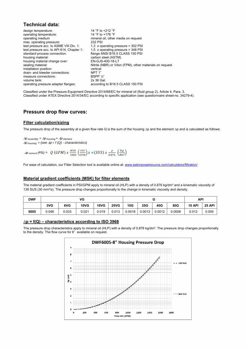
Technical data:
design temperature: 14 °F to +212 °F operating temperature: 14 °F to +176 °F operating medium mineral oil, other media on request max. operating pressure: 232 PSI test pressure acc. to ASME VIII Div. 1: 1,3 x operating pressure = 302 PSI test pressure acc. to API 614, Chapter 1: 1,5 x operating pressure = 348 PSI standard process connection: flange ANSI B16.5 CLASS 150 PSI housing material: carbon steel (ASTM) housing material change over: EN-GJS-400-18-LT sealing material: Nitrile (NBR) or Viton (FPM), other materials on request installation position: vertical drain- and bleeder connections: NPT 1” measure connections: BSPP ¼” volume tank: 2x 36 Gal. operating pressure adapter flanges: according to B16.5 CLASS 150 PSI Classified under the Pressure Equipment Directive 2014/68/EC for mineral oil (fluid group 2), Article 4, Para. 3. Classified under ATEX Directive 2014/34/EC according to specific application (see questionnaire sheet-no. 34279-4).
Pressure drop flow curves:
Filter calculation/sizing
The pressure drop of the assembly at a given flow rate Q is the sum of the housing ∆p and the element ∆p and is calculated as follows:
p assembly = p housing + p element p housing = (see p = f (Q) - characteristics)
For ease of calculation, our Filter Selection tool is available online at: www.eatonpowersource.com/calculators/filtration/
Material gradient coefficients (MSK) for filter elements
The material gradient coefficients in PSI/GPM apply to mineral oil (HLP) with a density of 0.876 kg/dm³ and a kinematic viscosity of 139 SUS (30 mm²/s). The pressure drop changes proportionally to the change in kinematic viscosity and density.
DWF VG G API
3VG 6VG 10VG 16VG 25VG 10G 25G 40G 80G 10 API 25 API
6005 0.048 0.033 0.021 0.019 0.013 0.0018 0.0013 0.0012 0.0008 0.012 0.005
∆p = f(Q) – characteristics according to ISO 3968
The pressure drop characteristics apply to mineral oil (HLP) with a density of 0,876 kg/dm³. The pressure drop changes proportionally to the density. The flow curve for 6” available on request.

Symbols: without indicator with
shut-off ball valve with electric
indicator AE 30 and AE 40
with visual-electric indicator
AE 50 and AE 62
with visual-electric indicator
AE 70 and AE 80
with visual indicator
OP
with visual-electric indicator
OE
with electronic sensor
VS5
Spare parts: item qty. designation dimension Article-no.
1 8 filter element 01E.1501… 2 8 O-ring 93 x 5 307588 (NBR) 307589 (FPM) 3 2 O-ring 17" ID x 0.210 CS 2375017093 (BUNA-N) 4 4 gasket kit of change over UKK 6” 6“ (DN150) 347916 (FPM) 4 gasket kit of change over UKK 8” 8” (DN200) 347931 (FPM)
5 6 screw plug NPT 1“ ST501Z35 6 1 clogging indicator, visual-electric AE see sheet-no.1609 7 1 clogging indicator, visual OP see sheet-no 1614 8 1 clogging indicator, visual-electric OE see sheet-no 1614 9 1 clogging sensor, electronic VS5 see sheet-no 1641 10 3 O-ring 14 x 2 304342 (NBR) 304722 (FPM) 11 1 O-ring 22 x 2 304708 (NBR) 304721 (FPM)
Test methods: Filter elements are tested according to the following ISO standards:
ISO 2941 Verification of collapse/burst resistance ISO 2942 Verification of fabrication integrity ISO 2943 Verification of material compatibility with fluids ISO 3723 Method for end load test ISO 3724 Verification of flow fatigue characteristics ISO 3968 Evaluation of pressure drop versus flow characteristics ISO 16889 Multi-pass method for evaluating filtration performance
North America 44 Apple Street Tinton Falls, NJ 07724
Toll Free: 800 656-3344 (North America only)
Tel: +1 732 212-4700 Europe/Africa/Middle East Auf der Heide 2 53947 Nettersheim, Germany
Tel: +49 2486 809-0
Friedensstraße 41 68804 Altlußheim, Germany
Tel: +49 6205 2094-0
An den Nahewiesen 24 55450 Langenlonsheim, Germany
Tel: +49 6704 204-0
China No. 3, Lane 280, Linhong Road Changning District, 200335 Shanghai, P.R. China
Tel: +86 21 5200-0099 Singapore 4 Loyang Lane #04-01/02 Singapore 508914
Tel: +65 6825-1668 Brazil Av. Julia Gaioli, 474 – Bonsucesso 07251-500 – Guarulhos, Brazil
Tel: +55 11 2465-8822
For more information, please email us at [email protected]
or visit www.eaton.com/filtration
© 2015 Eaton. All rights reserved. All trademarks and registered trademarks are the property of their respective owners. All information and recommendations appearing in this brochure concerning the use of products described herein are based on tests believed to be reliable. However, it is the user’s responsibility to determine the suitability for his own use of such products. Since the actual use by others is beyond our control, no guarantee, expressed or implied, is made by Eaton as to the effects of such use or the results to be obtained. Eaton assumes no liability arising out of the use by others of such products. Nor is the information herein to be construed as absolutely complete, since additional information may be necessary or desirable when particular or exceptional conditions or circumstances exist or because of applicable laws or government regulations.

Series DSF 176-331
363 PSI
PRESSURE FILTER, change over
Sheet No. 2148 C
EDV 09/15
Dimensions: inches Designs and performance values are subject to change.
Position. I: left filter-side in operation Position. II: right filter-side in operation
Dimensions:
type DSF 176 DSF 331 A 16.35 21.85 B 8.58 13.89 C 9.84 15.35
weight approx. 79 lbs. 84 lbs. volume tank 2x .31 Gal. 2x .52 Gal.

Pressure Filter
Series DSF 176-331
363 PSI
Description: Duplex pressure filter series DSF 176-331 are suitable for a working pressure up to 363 PSI. Pressure peaks can be absorbed with a sufficient safety margin.
A three-way-change-over valve integrated in the middle of the housing makes it possible to switch from the dirty filter-side to the clean filter-side without interruptingoperation. The filters can be installed as a suction filter, pressure filter or return-line filter. Filter elements are available down to a filter fineness of 4 µm(c).
Eaton filter elements are known for high intrinsic stability and an excellent filtration capability, a high dirt-retaining capacity and a long service life.
Eaton filter elements can be used for petroleum-based fluids, HW emulsions, water glycols, most synthetic fluids and lubrication fluids. Consult factory for specific fluid applications.
Eaton filter elements are available up to a pressure resistance of p 2320 PSI and a rupture strength of p 3625 PSI.
The internal valve is integrated into the filter head. After reaching the bypass pressure setting, the bypass valve will send unfiltered partial flow around the filter.
1. Type index:
1.1. Complete filter: (ordering example)
DSF. 176. 10VG. 16. E. P. -. FS. 7. -. -. AE1 2 3 4 5 6 7 8 9 10 11 12
1 series: DSF = duplex filter, change-over
2 nominal size: 176, 331
3 filter-material and filter-fineness: 80G, 40G, 25G stainless steel wire mesh 25VG, 16VG, 10VG, 6VG, 3VG microglass 25API, 10API microglass according to API 10P paper
4 filter element collapse rating: 16 = p 232 PSI
5 filter element design: E = single-end open
6 sealing material: P = Nitrile (NBR) V = Viton (FPM)
7 filter element specification: - = standard VA = stainless steel
8 process connection: FS = SAE-flange 3000 PSI UG = thread connection
9 process connection size: 7 = 1 ½“
10 filter housing specification: - = standard
11 internal valve: - = without S1 = with by-pass valve p 51 PSI S2 = with by-pass valve p 102 PSI
12 clogging indicator or clogging sensor: - = without AOR = visual, see sheet-no. 1606 AOC = visual, see sheet-no. 1606 AE = visual-electric, see sheet-no. 1615 VS5 = electronic, see sheet-no. 1619
To add an indicator to your filter, use the corresponding indicator data sheet to find the indicator details and add them to the filter assembly model code.
1.2. Filter element: (ordering example)
01E. 175. 10VG. 16. E. P. - 1 2 3 4 5 6 7
1 series: 01E. = filter element according to company standard
2 nominal size: 175, 330
3 - 7 see type index-complete filter
Accessories:
- SAE-counter flange, see sheet-no. 1652
.

Technical data:
design temperature: 14 °F to +212 °F operating temperature: 14 °F to +176 °F operating medium mineral oil, other media on request max. operating pressure: 363PSI test pressure: 725 PSI process connection: SAE-flange 3000 PSI or thread housing material: EN-GJS-400-18-LT sealing material: Nitrile (NBR) or Viton (FPM), other materials on request installation position: vertical
Classified under the Pressure Equipment Directive 2014/68/EC for mineral oil (fluid group 2), Article 4, Para. 3. Classified under ATEX Directive 2014/34/EC according to specific application (see questionnaire sheet-no. 34279-4).
Pressure drop flow curves:
Filter calculation/sizing
The pressure drop of the assembly at a given flow rate Q is the sum of the housing ∆p and the element ∆p and is calculated as follows:
p assembly = p housing + p element p housing = (see p = f (Q) - characteristics)
p element (PSI) = .
³
For ease of calculation our Filter Selection tool is available online at www.eatonpowersource.com/calculators/filtration/
Material gradient coefficients (MSK) for filter elements
The material gradient coefficients in PSI/GPM apply to mineral oil (HLP) with a density of 0.876 kg/dm³ and a kinematic viscosity of 139 SUS (30 mm²/s). The pressure drop changes proportionally to the change in kinematic viscosity and density.
DSF VG G P
3VG 6VG 10VG 16VG 25VG 25G 40G 80G 10P
176 2.078 1.443 0.923 0.804 0.549 0.0743 0.0694 0.0475 0.446
331 1.152 0.800 0.512 0.446 0.305 0.0421 0.0393 0.0269 0.247
∆p = f(Q) – characteristics according to ISO 3968
The pressure drop characteristics apply to mineral oil (HLP) with a density of 0.876 kg/dm³. The pressure drop changes proportionally to the density.

Symbols: without indicator with electric
indicator AE 30 and AE 40
with visual-electric indicator
AE 50 and AE 62
with visual-electric indicator
AE 70 and AE 80
with visual indicator
AOR/AOC
with electronic clogging sensor
VS5 filter without internal valve
filter with by-pass valve
Spare parts:
item qty. designation dimension article-no. DSF 176 DSF 331
1 2 filter element 01E.175… 01E.330… 2 2 O-ring 100 x 4 320540 (NBR) 332740 (FPM) 3 2 O-ring 75 x 3 302215 (NBR) 304729 (FPM) 4 2 O-ring 44 x 6 302222 (NBR) 304384 (FPM) 5 2 O-ring 18 x 3 304359 (NBR) 304399 (FPM) 6 2 spring Da = 52 304989 7 2 screw plug 1 BSPP 305303 8 4 screw plug ½ BSPP 304678 9 1 clogging indicator, visual AOR or AOC see sheet-no.1606
10 1 clogging indicator, visual-electric AE see sheet-no.1615 11 1 clogging sensor, electronic VS5 see sheet-no.1619 12 1 O-ring 15 x 1,5 315357 (NBR) 315427 (FPM) 13 1 O-ring 22 x 2 304708 (NBR) 304721 (FPM) 14 1 O-ring 14 x 2 304342 (NBR) 304722 (FPM) 15 1 screw plug 20913-4 309817 16 1 pressure balance valve 3/8“ 305000
item 15 execution only without clogging indicator or clogging sensor
Test methods: Filter elements are tested according to the following ISO standards:
ISO 2941 Verification of collapse/burst resistance ISO 2942 Verification of fabrication integrity ISO 2943 Verification of material compatibility with fluids ISO 3723 Method for end load test ISO 3724 Verification of flow fatigue characteristics ISO 3968 Evaluation of pressure drop versus flow characteristics ISO 16889 Multi-pass method for evaluating filtration performance
North America 44 Apple Street Tinton Falls, NJ 07724
Toll Free: 800 656-3344 (North America only)
Tel: +1 732 212-4700 Europe/Africa/Middle East Auf der Heide 2 53947 Nettersheim, Germany
Tel: +49 2486 809-0
Friedensstraße 41 68804 Altlußheim, Germany
Tel: +49 6205 2094-0
An den Nahewiesen 24 55450 Langenlonsheim, Germany
Tel: +49 6704 204-0
China No. 3, Lane 280, Linhong Road Changning District, 200335 Shanghai, P.R. China
Tel: +86 21 5200-0099 Singapore 4 Loyang Lane #04-01/02 Singapore 508914
Tel: +65 6825-1668 Brazil Av. Julia Gaioli, 474 – Bonsucesso 07251-500 – Guarulhos, Brazil
Tel: +55 11 2465-8822
For more information, please email us at [email protected]
or visit www.eaton.com/filtration
© 2015 Eaton. All rights reserved. All trademarks and registered trademarks are the property of their respective owners. All information and recommendations appearing in this brochure concerning the use of products described herein are based on tests believed to be reliable. However, it is the user’s responsibility to determine the suitability for his own use of such products. Since the actual use by others is beyond our control, no guarantee, expressed or implied, is made by Eaton as to the effects of such use or the results to be obtained. Eaton assumes no liability arising out of the use by others of such products. Nor is the information herein to be construed as absolutely complete, since additional information may be necessary or desirable when particular or exceptional conditions or circumstances exist or because of applicable laws or government regulations.
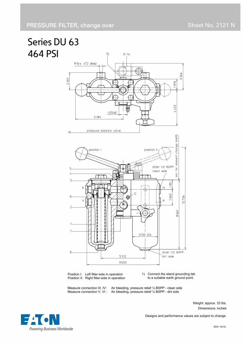
Series DU 63
464 PSI
PRESSURE FILTER, change over
Sheet No. 2121 N
EDV 10/15
Position I: Left filter-side in operation Position II: Right filter-side in operation
1) Connect the stand grounding tab to a suitable earth ground point.
Weight: approx. 33 lbs.
Dimensions: inches Designs and performance values are subject to change.
Measure connection III, IV: Air bleeding, pressure relief ½ BSPP - clean side Measure connection V, VI : Air bleeding, pressure relief ½ BSPP - dirt side

Pressure Filter
Series DU 63
464 PSI
Description: Duplex filter series DU63 have a working pressure up to 464 PSI. Pressure peaks can be absorbed with a sufficient safety margin.
A rotary slide valve integrated in the middle of the housing makes it possible to switch from the dirty filter-side to the clean filter-side without interrupting operation. These filters can be installed as suction filters.
The filter element consists of star-shaped, pleated filter material, which is supported on the inside by a perforated core tube and is bonded to the end caps with a high-quality adhesive. The flow direction is from outside to inside.
For cleaning the mesh element or changing the microglasselement, remove the cover and take out the element. The mesh elements are not guaranteed to maintain 100% performance after cleaning.
For filtration finer than 40 μm, use the disposable elements made of microglass. Filter elements as fine as 5 μm(c) are available; finer filter elements are available upon request.
Eaton-filter elements are known for a high intrinsic stability and an excellent filtration capability, a high dirt-retaining capacity and a long service life.
Eaton filter elements are suitable for all petroleum based fluids, HW-emulsions, most synthetic hydraulic fluids and lubrication oils.
The bypass valve is integrated in the filter cover. After reaching the bypass pressure setting, the bypass valve will send unfiltered partial flow around the filter.
Ship classifications available upon request.
Type index:
Complete filter: (ordering example)
DU. 63. 10VG. 30. E. P. -. UG. 4. -. -. AE1 2 3 4 5 6 7 8 9 10 11 12
1 series: DU = pressure filter, change over
2 nominal size: 63
3 filter-material and filter-fineness: 80G, 40G, 25G, 10G stainless steel wire mesh 25VG, 16VG, 10VG, 6VG, 3VG microglass 25API, 10API microglass according to API 10P paper
4 filter element collapse rating: 30 = p 435 PSI
5 filter element design: E = single end open
6 sealing material: P = Nitrile (NBR) V = Viton (FPM)
7 filter element specification: - = standard VA = stainless steel
8 process connection: UG = thread connection
9 process connection size: 4 = -12 SAE
10 filter housing specification: - = standard
11 internal valve: - = without S1 = with bypass valve p 51 PSI
12 clogging indicator or clogging sensor: - = without AOR = visual-electric, see sheet-no.1606 AOC = visual-electric, see sheet-no.1606 AE = visual-electric, see sheet-no.1615 VS5 = electronic, see sheet-no.1619
To add an indicator to your filter, use the corresponding indicator data sheet to find the indicator details and add them to the filter assembly model code.
Filter element: (ordering example)
01NL. 63. 10VG. 30. E. P. - 1 2 3 4 5 6 7
1 series: 01NL. = standard filter element according to DIN 24550, T3
2 nominal size: 63
3 - 7 see type index complete filter
Accessories:
- gauge port and bleeder connection, see sheet-no. 1650 - drain- and bleeder connection, see sheet-no. 1651

Technical data:
design temperature: 14 °F to +212 °F operating temperature: 14 °F to +176 °F operating medium mineral oil, other media on request max. operating pressure: 464 PSI test pressure: 900 PSI process connection: thread connection housing material: EN-GJS-400-18-LT sealing material: Nitrile (NBR) or Viton (FPM), other materials on request installation position: vertical measure connections: BSPP ¼ drain- and bleeder connections: BSPP ½ volume tank: 2x 0.17 Gal.
Classified under the Pressure Equipment Directive 2014/68/EC for mineral oil (fluid group 2), Article 4, Para. 3. Classified under ATEX Directive 2014/34/EC according to specific application (see questionnaire sheet-no. 34279-4).
Pressure drop flow curves:
Filter calculation/sizing
The pressure drop of the assembly at a given flow rate Q is the sum of the housing ∆p and the element ∆p and is calculated as follows:
p assembly = p housing + p element p housing = (see p = f (Q) - characteristics)
p element (PSI) = .
³
For ease of calculation our Filter Selection tool is available online at www.eatonpowersource.com/calculators/filtration/
Material gradient coefficients (MSK) for filter elements
The material gradient coefficients in psi/gpm apply to mineral oil (HLP) with a density of 0.876 kg/dm³ and a kinematic viscosity of 139 SUS (30 mm²/s). The pressure drop changes proportionally to the change in kinematic viscosity and density.
DU VG G P API
3VG 6VG 10VG 16VG 25VG 25G 40G 80G 10P 10API 25API
63 4.214 2.926 1.873 1.631 1.114 0.1131 0.1056 0.0723 0.946 0.993 0.455
∆p = f(Q) – characteristics according to ISO 3968
The pressure drop characteristics apply to mineral oil (HLP) with a density of 0.876 kg/dm³. The pressure drop changes proportionally to the density.

Symbols: without indicator with by-pass valve with electric
indicator AE 30 and AE 40
with visual-electric indicator
AE 50 and AE 62
with visual-electric indicator
AE 70 and AE 80
with visual indicator
AOR/AOC
with electronic clogging sensor
VS5
Spare parts:
item qty. designation dimension article-no. 1 2 filter element 01NL.63… 2 2 O-ring 22 x 3,5 304341 (NBR) 304392 (FPM) 3 2 O-ring 56 x 3 305072 (NBR) 305322 (FPM) 4 1 O-ring 42,52 x 2,62 304352 (NBR) 304393 (FPM) 5 2 O-ring 18 x 3 304359 (NBR) 304399 (FPM) 6 2 O-ring 48 x 3 304357 (NBR) 304404 (FPM) 7 1 screw plug 1 ¼ BSPP 308530 8 6 screw plug ½ BSPP 304678 9 1 clogging indicator, visual AOR or AOC see sheet-no. 1606 10 1 clogging indicator, visual-electric AE see sheet-no. 1615 11 1 clogging sensor, electronic VS5 see sheet-no. 1619 12 1 O-ring 15 x 1,5 315357 (NBR) 315427 (FPM) 13 1 O-ring 22 x 2 304708 (NBR) 304721 (FPM) 14 3 O-ring 14 x 2 304342 (NBR) 304722 (FPM) 15 2 screw plug ¼ BSPP 305003 16 1 pressure balance valve 3/8“ 305000
item 15 execution only without clogging indicator or clogging sensor
Test methods: Filter elements are tested according to the following ISO standards:
ISO 2941 Verification of collapse/burst resistance ISO 2942 Verification of fabrication integrity ISO 2943 Verification of material compatibility with fluids ISO 3723 Method for end load test ISO 3724 Verification of flow fatigue characteristics ISO 3968 Evaluation of pressure drop versus flow characteristics ISO 16889 Multi-pass method for evaluating filtration performance
North America 44 Apple Street Tinton Falls, NJ 07724
Toll Free: 800 656-3344 (North America only)
Tel: +1 732 212-4700 Europe/Africa/Middle East Auf der Heide 2 53947 Nettersheim, Germany
Tel: +49 2486 809-0
Friedensstraße 41 68804 Altlußheim, Germany
Tel: +49 6205 2094-0
An den Nahewiesen 24 55450 Langenlonsheim, Germany
Tel: +49 6704 204-0
China No. 3, Lane 280, Linhong Road Changning District, 200335 Shanghai, P.R. China
Tel: +86 21 5200-0099 Singapore 4 Loyang Lane #04-01/02 Singapore 508914
Tel: +65 6825-1668 Brazil Av. Julia Gaioli, 474 – Bonsucesso 07251-500 – Guarulhos, Brazil
Tel: +55 11 2465-8822
For more information, please email us at [email protected]
or visit www.eaton.com/filtration
© 2015 Eaton. All rights reserved. All trademarks and registered trademarks are the property of their respective owners. All information and recommendations appearing in this brochure concerning the use of products described herein are based on tests believed to be reliable. However, it is the user’s responsibility to determine the suitability for his own use of such products. Since the actual use by others is beyond our control, no guarantee, expressed or implied, is made by Eaton as to the effects of such use or the results to be obtained. Eaton assumes no liability arising out of the use by others of such products. Nor is the information herein to be construed as absolutely complete, since additional information may be necessary or desirable when particular or exceptional conditions or circumstances exist or because of applicable laws or government regulations.

Series DU 101-401
464 PSI
PRESSURE FILTER, change over
Sheet No. 2117 U
EDV 10/15
Position I: Left filter-side in operation Position II: Right filter-side in operation
1) Connect the stand grounding tab to a suitable earth ground point.
Dimensions: type SAE-
connection A B C D E F G H J K L M N O P Q R S T U V weight
DU 101 SAE 1 ¼“1) 18.23 12.20 8.27 10.43 2.17 3.15 .87 .63 3.74 7.09 2.36 3.94 1.96 5.51 4.53 5.51 4.53 .47 1.19 2.31 M10/.75 dp. 51 lbs. DU 101 SAE 1 ¼“ DU 251 SAE 2“ 2) 20.55 14.97 10.23 12.56 3.31 3.94 - .75 5.12 9.45 3.82 4.33 2.99 6.10 5.12 7.28 6.30 .53 1.69 3.10 M12/.71 dp. 88 lbs. DU 251 SAE 2“ DU 401 SAE 2“ 24.88 20.87 16.14 18.46 3.31 3.94 - .75 5.12 9.45 3.82 4.33 2.99 6.10 5.12 7.28 6.30 .53 1.69 3.10 M12/.71 dp. 110 lbs.
1) by counter flange BFS.6.A.33,7x2,6.St.P.3000
2) by counter flange BFS.8.A.48,3x3,7.St.P.3000
Dimensions: inches Designs and performance values are subject to change.

Pressure Filter
Series DU 101-401
464 PSI
Description: Duplex filter series DU 101-401 have a working pressure up to 464 PSI. Pressure peaks can be absorbed with a sufficient safety margin.
A three way changeover valve which is integrated in the middle of the housing makes it possible to switch from the dirty filter-side to the clean filter-side without interrupting operation. These filters can be installed as suction filters.
The filter element consists of star-shaped, pleated filter material, which is supported on the inside by a perforated core tube and is bonded to the end caps with a high-quality adhesive. The flow direction is from outside to inside.
For cleaning the mesh element or changing the microglass element, remove the cover and take out the element. The mesh elements are not guaranteed to maintain 100% performance after cleaning.
For filtration finer than 40 μm use the disposable elements made of microglass. Filter elements as fine as 5 μm(c) are available; finer filter elements on request.
Eaton filter elements are known for a high intrinsic stability and an excellent filtration capability, a high dirt-retaining capacity and a long service life.
Eaton filter elements are suitable for all petroleum based fluids, HW-emulsions, most synthetic hydraulic fluids and lubrication oils.
Ship classifications available upon request.
Type index:
Complete filter: (ordering example)
DU. 251. 10VG. 30. E. P. -. FS. 8. -. -. AE1 2 3 4 5 6 7 8 9 10 11 12
1 series: DU = pressure filter, change over
2 nominal size: 101, 251, 401
3 filter-material and filter-fineness: 80G, 40G, 25G, 10G stainless steel wire mesh 25VG, 16VG, 10VG, 6VG, 3VG microglass 25API, 10API microglass according to API 10P paper
4 filter element collapse rating: 16 = p 232 PSI (01N.100)
30 = p 435 PSI (01NL.250/400)
5 filter element design: E = single end open S = with by-pass valve p 29 PSI S1 = with by-pass valve p 51 PSI
6 sealing material: P = Nitrile (NBR) V = Viton (FPM)
7 filter element specification: (see catalog) - = standard VA = stainless steel IS06 = for HFC application, see sheet-no. 31601
8 process connection: FS = SAE-flange 3000 PSI
9 process connection size: 6 = 1 ¼” (DU 101) 8 = 2“ (DU 251/401)
10 filter housing specification: (see catalog) - = standard IS12 = for stainless steel ball valve, see sheet-no. 41028 IS20 = ASME VIII Div.1 with ASME equivalent material,
see sheet-no. 55217 (operating pressure max. 232 PSI)
11 internal valve: - = without
12 clogging indicator or clogging sensor: - = without AOR = visual-electric, see sheet-no.1606 AOC = visual-electric, see sheet-no.1606 AE = visual-electric, see sheet-no.1609 OP = visual, see sheet-no.1628 OE = visual-electric, see sheet-no.1628 VS5 = electronic, see sheet-no.1641
To add an indicator to your filter, use the corresponding indicator data sheet to find the indicator details and add them to the filter assembly model code.
Filter element: (ordering example)
01NL. 250. 10VG. 30. E. P. - 1 2 3 4 5 6 7
1 series: 01N. = standard filter element according to EATON specification
01NL. = standard filter element according to DIN 24550, T3
2 Nominal size: 100 (01N.), 250,400 (01NL.)
3 - 7 see type index for complete filter
Accessories:
- gauge port and bleeder connection, see sheet-no. 1650 - drain- and bleeder connection, see sheet-no. 1651 - SAE-counter flange, see sheet-no. 1652 - shut-off valve, see sheet-no. 1655

Technical data:
design temperature: 14 °F to +212 °F operating temperature: 14 °F to +176 °F operating medium mineral oil, other media on request max. operating pressure: 464 PSI max. operating pressure at IS20: 232 PSI test pressure: 900 PSI test pressure at IS20: 464 PSI process connection: SAE-flange 3000 PSI housing material: EN-GJS-400-18-LT sealing material: Nitrile (NBR) or Viton (FPM), other materials on request installation position: vertical measure connections: BSPP ¼ drain- and bleeder connections: BSPP ½ volume tank DU 101: 2x .23 Gal. DU 251: 2x .66 Gal. DU 401: 2x .97 Gal.
Classified under the Pressure Equipment Directive 2014/68/EC for mineral oil (fluid group 2), Article 4, Para. 3. Classified under ATEX Directive 2014/34/EC according to specific application (see questionnaire sheet-no. 34279-4).
Pressure drop flow curves:
Filter calculation/sizing
The pressure drop of the assembly at a given flow rate Q is the sum of the housing ∆p and the element ∆p and is calculated as follows:
p assembly = p housing + p element p housing = (see p = f (Q) - characteristics)
p element (PSI) = .
³
For ease of calculation our Filter Selection tool is available online at www.eatonpowersource.com/calculators/filtration/
Material gradient coefficients (MSK) for filter elements
The material gradient coefficients in psi/gpm apply to mineral oil (HLP) with a density of 0.876 kg/dm³ and a kinematic viscosity of 139 SUS (30 mm²/s). The pressure drop changes proportionally to the change in kinematic viscosity and density.
DU VG G P API
3VG 6VG 10VG 16VG 25VG 25G 40G 80G 10P 10API 25API
101 2.473 1.717 1.099 0.957 0.654 0.0651 0.0607 0.0416 0.504 0.582 0.266
251 1.140 0.792 0.507 0.441 0.301 0.0339 0.0316 0.0217 0.231 0.260 0.119
401 0.700 0.486 0.311 0.271 0.185 0.0207 0.0194 0.0133 0.121 0.159 0.073
∆p = f(Q) – characteristics according to ISO 3968
The pressure drop characteristics apply to mineral oil (HLP) with a density of 0.876 kg/dm³. The pressure drop changes proportionally to the density.
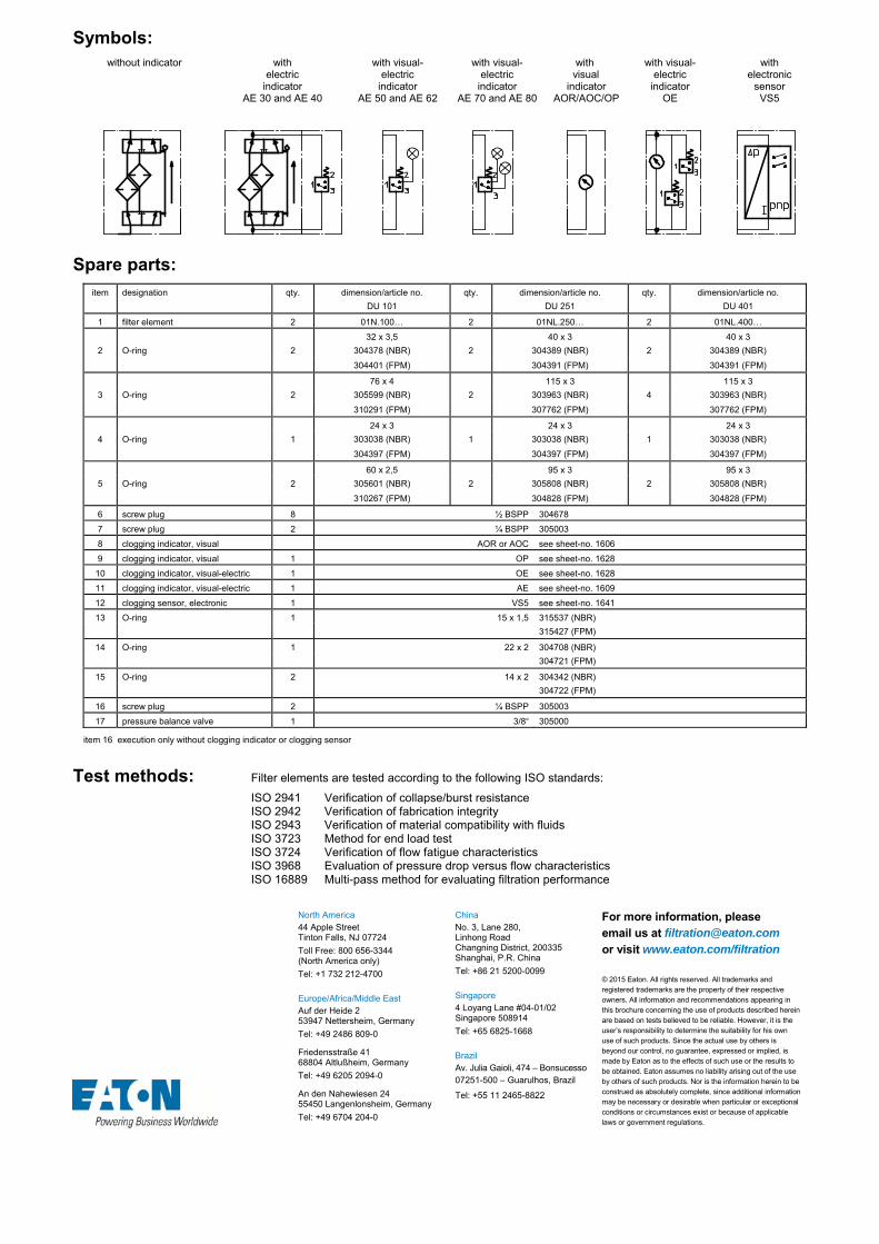
Symbols: without indicator
with
electric indicator
AE 30 and AE 40
with visual- electric
indicator AE 50 and AE 62
with visual-electric
indicator AE 70 and AE 80
with visual
indicator AOR/AOC/OP
with visual-electric
indicator OE
with electronic
sensor VS5
Spare parts:
item designation qty. dimension/article no. qty. dimension/article no. qty. dimension/article no.
DU 101 DU 251 DU 401
1 filter element 2 01N.100… 2 01NL.250… 2 01NL.400…
32 x 3,5 40 x 3 40 x 3
2 O-ring 2 304378 (NBR) 2 304389 (NBR) 2 304389 (NBR)
304401 (FPM) 304391 (FPM) 304391 (FPM)
76 x 4 115 x 3 115 x 3
3 O-ring 2 305599 (NBR) 2 303963 (NBR) 4 303963 (NBR)
310291 (FPM) 307762 (FPM) 307762 (FPM)
24 x 3 24 x 3 24 x 3
4 O-ring 1 303038 (NBR) 1 303038 (NBR) 1 303038 (NBR)
304397 (FPM) 304397 (FPM) 304397 (FPM)
60 x 2,5 95 x 3 95 x 3
5 O-ring 2 305601 (NBR) 2 305808 (NBR) 2 305808 (NBR)
310267 (FPM) 304828 (FPM) 304828 (FPM)
6 screw plug 8 ½ BSPP 304678
7 screw plug 2 ¼ BSPP 305003
8 clogging indicator, visual AOR or AOC see sheet-no. 1606
9 clogging indicator, visual 1 OP see sheet-no. 1628
10 clogging indicator, visual-electric 1 OE see sheet-no. 1628
11 clogging indicator, visual-electric 1 AE see sheet-no. 1609
12 clogging sensor, electronic 1 VS5 see sheet-no. 1641
13 O-ring 1 15 x 1,5 315537 (NBR)
315427 (FPM)
14 O-ring 1 22 x 2 304708 (NBR)
304721 (FPM)
15 O-ring 2 14 x 2 304342 (NBR)
304722 (FPM)
16 screw plug 2 ¼ BSPP 305003
17 pressure balance valve 1 3/8“ 305000
item 16 execution only without clogging indicator or clogging sensor
Test methods: Filter elements are tested according to the following ISO standards:
ISO 2941 Verification of collapse/burst resistance ISO 2942 Verification of fabrication integrity ISO 2943 Verification of material compatibility with fluids ISO 3723 Method for end load test ISO 3724 Verification of flow fatigue characteristics ISO 3968 Evaluation of pressure drop versus flow characteristics ISO 16889 Multi-pass method for evaluating filtration performance
North America 44 Apple Street Tinton Falls, NJ 07724
Toll Free: 800 656-3344 (North America only)
Tel: +1 732 212-4700 Europe/Africa/Middle East Auf der Heide 2 53947 Nettersheim, Germany
Tel: +49 2486 809-0
Friedensstraße 41 68804 Altlußheim, Germany
Tel: +49 6205 2094-0
An den Nahewiesen 24 55450 Langenlonsheim, Germany
Tel: +49 6704 204-0
China No. 3, Lane 280, Linhong Road Changning District, 200335 Shanghai, P.R. China
Tel: +86 21 5200-0099 Singapore 4 Loyang Lane #04-01/02 Singapore 508914
Tel: +65 6825-1668 Brazil Av. Julia Gaioli, 474 – Bonsucesso 07251-500 – Guarulhos, Brazil
Tel: +55 11 2465-8822
For more information, please email us at [email protected]
or visit www.eaton.com/filtration
© 2015 Eaton. All rights reserved. All trademarks and registered trademarks are the property of their respective owners. All information and recommendations appearing in this brochure concerning the use of products described herein are based on tests believed to be reliable. However, it is the user’s responsibility to determine the suitability for his own use of such products. Since the actual use by others is beyond our control, no guarantee, expressed or implied, is made by Eaton as to the effects of such use or the results to be obtained. Eaton assumes no liability arising out of the use by others of such products. Nor is the information herein to be construed as absolutely complete, since additional information may be necessary or desirable when particular or exceptional conditions or circumstances exist or because of applicable laws or government regulations.

Series DU 631-1950
464 PSI
Dimensions: type SAE-
connection A B C D E F G H J K L M N O P Q R S T weight
DU 631 SAE 2 ½“ 27.28 22.36 19.56 4.33 4.52 .94 6.29 11.29 3.26 4.76 5.23 5.51 4.52 8.26 7.28 .53 2.00 3.50 M12, .71 dp. 198 lbs.DU 1001 SAE 3“ 28.22 23.07 19.88 3.68 5.51 1.12 8.07 14.96 3.97 5.39 5.94 8.26 6.69 10.43 8.85 .70 2.44 4.18 M16, .91 dp. 255 lbs.DU 1950 SAE 3“ 44.05 38.89 35.70 3.68 5.51 1.12 8.07 14.96 3.97 5.39 5.94 8.26 6.69 10.43 8.85 .70 2.44 4.18 M16, .91 dp. 374 lbs.
PRESSURE FILTER, change over
Sheet No. 2118 M
EDV 10/15
Position I: Left filter-side in operation Position II: Right filter-side in operation
1) Connect the stand grounding tab to a suitable earth ground point.
Dimensions: inches Designs and performance values are subject to change.

Pressure Filter
Series DU 631-1950
464 PSI
Description: Duplex filter series DU 631-1950 have a working pressure up to 464 PSI. Pressure peaks can be absorbed with a sufficient safety margin.
A three way changeover valve integrated in the middle of the housing makes it possible to switch from the dirty filter-side to the clean filter-side without interrupting operation. These filters can be installed as suction filters.
The filter element consists of star-shaped, pleated filter material, which is supported on the inside by a perforated core tube and is bonded to the end caps with a high-quality adhesive. The flow direction is from outside to inside.
For cleaning the mesh element or changing the microglass element, remove the cover and take out the element. The mesh elements are not guaranteed to maintain 100% performance after cleaning.
For filtration finer than 40 μm use the disposable elements made of microglass. Filter elements as fine as 5 μm(c) are available; finer filter elements on request.
Eaton filter elements are known for a high intrinsic stability and an excellent filtration capability, a high dirt-retaining capacity and a long service life.
Eaton filter elements are suitable for all petroleum based fluids, HW-emulsions, most synthetic hydraulic fluids and lubrication oils.
The internal valve is integrated in the filter cover. After reaching the bypass pressure setting, the bypass valve will send unfiltered partial flow around the filter.
Ship classifications available upon request.
Type index:
Complete filter: (ordering example)
DU. 631. 10VG. 30. E. P. -. FS. 9. -. -. AE1 2 3 4 5 6 7 8 9 10 11 12
1 series: DU = pressure filter, change over
2 nominal size: 631, 1001, 1950
3 filter-material and filter-fineness: 80G, 40G, 25G, 10G stainless steel wire mesh 25VG, 16VG, 10VG, 6VG, 3VG microglass 25API, 10API microglass according to API 10P paper
4 filter element collapse rating: 30 = p 435 PSI (01NL.630) 10 = p 146 PSI (01NR.1000/1001)
5 filter element design: E = single end open (01NL.630) S = with bypass valve p 29 PSI (01NL.630) S1 = with bypass valve p 51 PSI (01NL.630) B = both sides open (01NR.1001)
6 sealing material: P = Nitrile (NBR) V = Viton (FPM)
7 filter element specification: (see catalog) - = standard VA = stainless steel IS06 = for HFC applications, see sheet-no. 31601 IS07 = for oil/amonia mixtures (NH3), see sheet-no. 31602
8 process connection: FS = SAE-flange 3000 PSI
9 process connection size: 9 = 2 ½” (DU 631) A = 3“ (DU 1001/1950)
10 filter housing specification: (see catalog) - = standard IS06 = for HFC applications, see sheet-no. 31605 IS12 = for stainless steel ball valve, see sheet-no. 41028 IS20 = ASME VIII Div.1 with ASME equivalent material,
see sheet-no. 55217 (operating pressure max. 232 PSI)
11 internal valve: - = without S = with bypass valve p 29 PSI (DU 1001/1950) S1 = with bypass valve p 51 PSI (DU 1001/1950)
12 clogging indicator or clogging sensor: - = without AOR = visual-electric, see sheet-no.1606 AOC = visual-electric, see sheet-no.1606 AE = visual-electric, see sheet-no.1609 OP = visual, see sheet-no.1628 OE = visual-electric, see sheet-no.1628 VS5 = electronic, see sheet-no.1641
To add an indicator to your filter, use the corresponding indicator data sheet to find the indicator details and add them to the filter assembly model code.
Filter element: (ordering example)
01NL. 630. 10VG. 30. E. P. - 1 2 3 4 5 6 7
1 series: 01NL. = standard filter element according to DIN 24550, T3 01NR. = standard-return-line filter element according to DIN 24550, T4
2 nominal size: 630 (01NL.), 1000 (01NR.)
3 - 7 see type index for complete filter
Accessories:
- gauge port and bleeder connection, see sheet-no. 1650 - drain- and bleeder connection, see sheet-no. 1651 - SAE-counter flange, see sheet-no. 1652 - shut-off valve, see sheet-no. 1655

Technical data:
design temperature: 14 °F to +212 °F operating temperature: 14 °F to +176 °F operating medium mineral oil, other media on request max. operating pressure: 464 PSI max. operating pressure at IS20: 232 PSI test pressure: 900 PSI test pressure at IS20: 464 PSI process connection: SAE-flange 3000 PSI housing material: EN-GJS-400-18-LT sealing material: Nitrile (NBR) or Viton (FPM), other materials on request installation position: vertical measure connections: BSPP ¼ drain- and bleeder connections: BSPP ½ volume tank DU 631: 2x 1.5 Gal. DU 1001: 2x 3.4 Gal. DU 1950: 2x 6.1 Gal.
Classified under the Pressure Equipment Directive 2014/68/EC for mineral oil (fluid group 2), Article 4, Para. 3. Classified under ATEX Directive 2014/34/EC according to specific application (see questionnaire sheet-no. 34279-4).
Pressure drop flow curves:
Filter calculation/sizing
The pressure drop of the assembly at a given flow rate Q is the sum of the housing ∆p and the element ∆p and is calculated as follows:
p assembly = p housing + p element p housing = (see p = f (Q) - characteristics)
p element (PSI) = .
³
For ease of calculation our Filter Selection tool is available online at www.eatonpowersource.com/calculators/filtration/
Material gradient coefficients (MSK) for filter elements
The material gradient coefficients in psi/gpm apply to mineral oil (HLP) with a density of 0.876 kg/dm³ and a kinematic viscosity of 139 SUS (30 mm²/s). The pressure drop changes proportionally to the change in kinematic viscosity and density.
DU VG G P API
3VG 6VG 10VG 16VG 25VG 25G 40G 80G 10P 10API 25API
631 0.534 0.371 0.237 0.207 0.141 0.1735 0.1619 0.1109 0.112 0.121 0.056
1001 0.237 0.165 0.105 0.092 0.063 0.0061 0.0057 0.0039 0.051 0.053 0.024
1950 0.118 0.082 0.053 0.046 0.031 0.0030 0.0028 0.0019 0.026 0.027 0.012
∆p = f(Q) – characteristics according to ISO 3968
The pressure drop characteristics apply to mineral oil (HLP) with a density of 0.876 kg/dm³. The pressure drop changes proportionally to the density.

Symbols: without indicator with by-pass valve with electric
indicator AE 30 and AE 40
with visual-electric indicator
AE 50 and AE 62
with visual-electric indicator
AE 70 and AE 80
with visual indicator
OP/AOR/AOC
with visual-electrical indicator
OE
with electronic clogging sensor VS5
Spare parts:
item designation qty. dimension and qty. dimension and qty. dimension and article-no. DU 631 article-no. DU 1001 article-no. DU 1950
1 filter element 2 01NL.630… 2 01NR.1000… 4 01NR.1000…
60 x 3,5 90 x 4 90 x 42 O-ring 2 304377 (NBR) 4 306941 (NBR) 8 306941 (NBR)
304398 (FPM) 307031 (FPM) 307031 (FPM)
125 x 3 185 x 4 185 x 43 O-ring 2 306025 (NBR) 2 305593 (NBR) 4 305593 (NBR)
307358 (FPM) 306309 (FPM) 306309 (FPM)
4 O-ring 1 24 x 3 304038 (NBR) 304397 (FPM)
5 O-ring 2 115 x 3 303963 (NBR) 307762 (FPM) 140 x 3 304604 (NBR) 307541 (FPM)
6 O-ring 1 96 x 4 305190 (NBR) 308148 (FPM) 120 x 4 305300 (NBR) 307991 (FPM)
7 O-ring 1 32 x 2,5 306843 (NBR) 308268 (FPM) 32 x 2,5 306843 (NBR) 308268 (FPM)
8 O-ring 2 69,45 x 3,53 85,32 x 3,53 305868 (NBR) 305590 (NBR)
307357 (FPM) 306308 (FPM)
9 screw plug 8 ½ BSPP 304678 8 ½ BSPP 304678 10 ½ BSPP 304678
10 screw plug 2 ¼ BSPP 305003
11 connecting pipe 2 - 3.543 dia 313233
12 clogging indicator, visual 1 AOR or AOC see sheet-no. 1606
13 clogging indicator, visual 1 OP see sheet-no. 1628
14 clogging indicator, visual-electric 1 OE see sheet-no. 1628
15 clogging indicator, visual-electric 1 AE see sheet-no. 1609
16 clogging sensor, electronic 1 VS5 see sheet-no. 1641
17 O-ring 1 15 x 1,5 315357 (NBR) 315427 (FPM)
18 O-ring 1 22 x 2 304708 (NBR) 304721 (FPM)
19 O-ring 2 14 x 2 304342 (NBR) 304722 (FPM)
20 screw plug 2 ¼ BSPP 305003
21 pressure balance valve 1 3/8“ 305000
item 20 execution only without clogging indicator or clogging sensor
Test methods: Filter elements are tested according to the following ISO standards:
ISO 2941 Verification of collapse/burst resistance ISO 2942 Verification of fabrication integrity ISO 2943 Verification of material compatibility with fluids ISO 3723 Method for end load test ISO 3724 Verification of flow fatigue characteristics ISO 3968 Evaluation of pressure drop versus flow characteristics ISO 16889 Multi-pass method for evaluating filtration performance
North America 44 Apple Street Tinton Falls, NJ 07724
Toll Free: 800 656-3344 (North America only)
Tel: +1 732 212-4700 Europe/Africa/Middle East Auf der Heide 2 53947 Nettersheim, Germany
Tel: +49 2486 809-0
Friedensstraße 41 68804 Altlußheim, Germany
Tel: +49 6205 2094-0
An den Nahewiesen 24 55450 Langenlonsheim, Germany
Tel: +49 6704 204-0
China No. 3, Lane 280, Linhong Road Changning District, 200335 Shanghai, P.R. China
Tel: +86 21 5200-0099 Singapore 4 Loyang Lane #04-01/02 Singapore 508914
Tel: +65 6825-1668 Brazil Av. Julia Gaioli, 474 – Bonsucesso 07251-500 – Guarulhos, Brazil
Tel: +55 11 2465-8822
For more information, please email us at [email protected]
or visit www.eaton.com/filtration
© 2015 Eaton. All rights reserved. All trademarks and registered trademarks are the property of their respective owners. All information and recommendations appearing in this brochure concerning the use of products described herein are based on tests believed to be reliable. However, it is the user’s responsibility to determine the suitability for his own use of such products. Since the actual use by others is beyond our control, no guarantee, expressed or implied, is made by Eaton as to the effects of such use or the results to be obtained. Eaton assumes no liability arising out of the use by others of such products. Nor is the information herein to be construed as absolutely complete, since additional information may be necessary or desirable when particular or exceptional conditions or circumstances exist or because of applicable laws or government regulations.

Series DU 635
464 PSI
PRESSURE FILTER, change over
Sheet No. 2128 K
EDV 10/15
Position I: Left filter-side in operation Position II: Right filter-side in operation
1) Connect the stand grounding tab to a suitable earth ground point.
Weight: approx. 200 lbs.
Dimensions: inches Designs and performance values are subject to change.

Pressure Filter
Series DU 635
464 PSI
Description: Duplex filter series DU635 have a working pressure up to 464 PSI. Pressure peaks can be absorbed with a sufficient safety margin.
Change-over ball valve between the two filter housings makes it possible to switch from the dirty filter-side to the clean filter-side without interruting operation.These filters can be installed as suction filters.
The filter element consists of star-shaped, pleated filter material, which is supported on the inside by a perforated core tube and is bonded to the end caps with a high-quality adhesive. The flow direction is from outside to inside.
For cleaning the mesh element or changing the microglass element, remove the cover and take out the element. The mesh elements are not guaranteed to maintain 100% performance after cleaning.
For filtration finer than 40 μm, use the disposable elements made of microglass. Filter elements as fine as 5 μm(c) are available; finer filter elements are available upon request.
Eaton-filter elements are known for a high intrinsic stability and an excellent filtration capability, a high dirt-retaining capacity and a long service life.
Eaton filter elements are suitable for all petroleum based fluids, HW-emulsions, most synthetic hydraulic fluids and lubrication oils.
Ship classifications available upon request.
Type index:
Complete filter: (ordering example)
DU. 635.10VG. 30. E. P. -. FS. 9. -. -. AE1 2 3 4 5 6 7 8 9 10 11 12
1 series: DU = pressure filter, change over
2 nominal size: 635
3 filter-material and filter-fineness: 80G, 40G, 25G, 10G stainless steel wire mesh 25VG, 16VG, 10VG, 6VG, 3VG microglass 25API, 10API microglass according to API 10P paper
4 filter element collapse rating: 30 = p 435 PSI
5 filter element design: E = single end open S = with by-pass valve p 29 PSI S1 = with by-pass valve p 51 PSI
6 sealing material: P = Nitrile (NBR) V = Viton (FPM)
7 filter element specification: (see catalog) - = standard VA = stainless steel IS06 = for HFC applications, see sheet-no. 31601 IS07 = for oil/amonia mixtures (NH3), see sheet-no. 31602
8 process connection: FS = SAE-flange 3000 PSI
9 process connection size: 9 = 2 ½“
10 filter housing specification: (see catalog) - = standard IS06 = for HFC applications, see sheet-no. 31605 IS12 = for stainless steel ball valve, see sheet-no. 41028 IS20 = ASME VIII Div.1 with ASME equivalent material,
see sheet-no. 55217 (operating pressure max. 232 PSI)
11 internal valve: - = without
12 clogging indicator or clogging sensor: - = without AOR = visual-electric, see sheet-no.1606 AOC = visual-electric, see sheet-no.1606 AE = visual-electric, see sheet-no.1609 OP = visual, see sheet-no.1628 OE = visual-electric, see sheet-no.1628 VS5 = electronic, see sheet-no.1641
To add an indicator to your filter, use the corresponding indicator data sheet to find the indicator details and add them to the filter assembly model code.
Filter element: (ordering example)
01NL. 630. 10VG. 30. E. P. - 1 2 3 4 5 6 7
1 series: 01NL. = standard filter element according to DIN 24550, T3
2 nominal size: 630
3 - 7 see type index complete filter
Accessories:
- gauge port and bleeder connection, see sheet-no. 1650 - drain- and bleeder connection, see sheet-no. 1651 - SAE-counter flange, see sheet-no. 1652 - shut-off valve, see sheet-no. 1655

Technical data:
design temperature: 14 °F to +212 °F operating temperature: 14 °F to +176 °F operating medium mineral oil, other media on request max. operating pressure: 464 PSI max. operating pressure at IS20: 232 PSI test pressure: 900 PSI test pressure at IS20: 464 PSI process connection: SAE-flange 3000 PSI housing material: EN-GJS-400-18-LT switching housing material: S355J2+N sealing material: Nitrile (NBR) or Viton (FPM), other materials on request installation position: vertical measure connections: BSPP ¼ drain- and bleeder connections: BSPP ½ volume tank: 2x 1.5 Gal.
Classified under the Pressure Equipment Directive 2014/68/EC for mineral oil (fluid group 2), Article 4, Para. 3. Classified under ATEX Directive 2014/34/EC according to specific application (see questionnaire sheet-no. 34279-4).
Pressure drop flow curves: Filter calculation/sizing
The pressure drop of the assembly at a given flow rate Q is the sum of the housing ∆p and the element ∆p and is calculated as follows:
p assembly = p housing + p element p housing = (see p = f (Q) - characteristics)
p element (PSI) = .
³
For ease of calculation our Filter Selection tool is available online at www.eatonpowersource.com/calculators/filtration/
Material gradient coefficients (MSK) for filter elements
The material gradient coefficients in psi/gpm apply to mineral oil (HLP) with a density of 0,876 kg/dm³ and a kinematic viscosity of 139 SUS (30 mm²/s). The pressure drop changes proportionally to the change in kinematic viscosity and density.
DU VG G P API
3VG 6VG 10VG 16VG 25VG 25G 40G 80G 10P 10API 25API
635 0.534 0.371 0.237 0.207 0.141 0.1735 0.1619 0.1109 0.112 0.121 0.056
∆p = f(Q) – characteristics according to ISO 3968
The pressure drop characteristics apply to mineral oil (HLP) with a density of 0.876 kg/dm³. The pressure drop changes proportionally to the density.
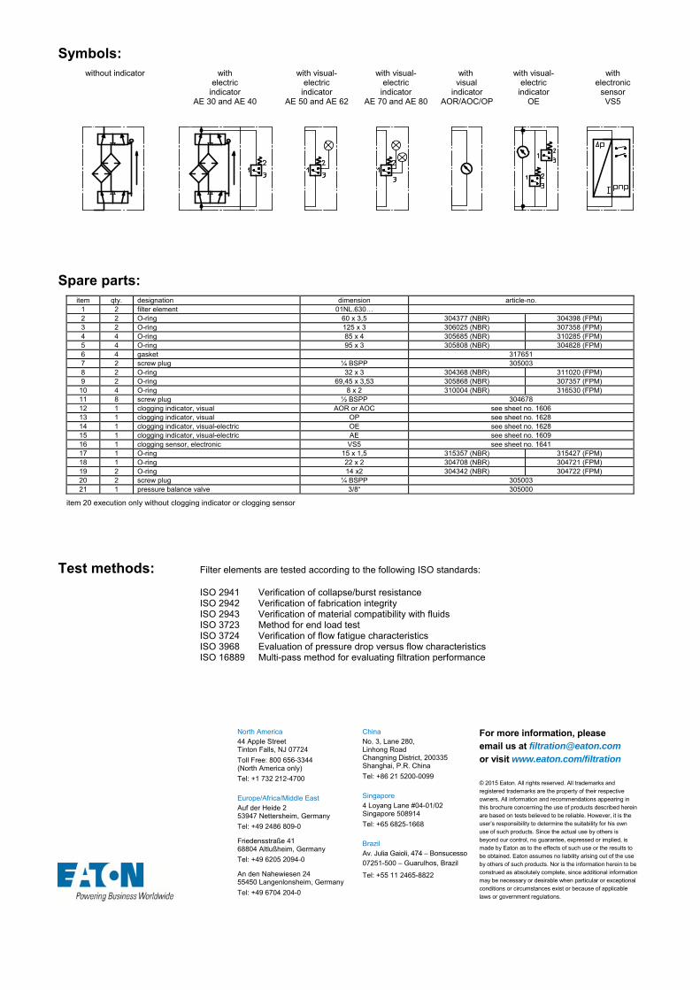
Symbols: without indicator
with
electric indicator
AE 30 and AE 40
with visual- electric
indicator AE 50 and AE 62
with visual-electric
indicator AE 70 and AE 80
with visual
indicator AOR/AOC/OP
with visual-electric
indicator OE
with electronic
sensor VS5
Spare parts: item qty. designation dimension article-no.
1 2 filter element 01NL.630… 2 2 O-ring 60 x 3,5 304377 (NBR) 304398 (FPM) 3 2 O-ring 125 x 3 306025 (NBR) 307358 (FPM) 4 4 O-ring 85 x 4 305685 (NBR) 310285 (FPM) 5 4 O-ring 95 x 3 305808 (NBR) 304828 (FPM) 6 4 gasket 317651 7 2 screw plug ¼ BSPP 305003 8 2 O-ring 32 x 3 304368 (NBR) 311020 (FPM) 9 2 O-ring 69,45 x 3,53 305868 (NBR) 307357 (FPM)
10 4 O-ring 8 x 2 310004 (NBR) 316530 (FPM) 11 8 screw plug ½ BSPP 304678 12 1 clogging indicator, visual AOR or AOC see sheet no. 1606 13 1 clogging indicator, visual OP see sheet no. 1628 14 1 clogging indicator, visual-electric OE see sheet no. 1628 15 1 clogging indicator, visual-electric AE see sheet no. 1609 16 1 clogging sensor, electronic VS5 see sheet no. 1641 17 1 O-ring 15 x 1,5 315357 (NBR) 315427 (FPM) 18 1 O-ring 22 x 2 304708 (NBR) 304721 (FPM) 19 2 O-ring 14 x2 304342 (NBR) 304722 (FPM) 20 2 screw plug ¼ BSPP 305003 21 1 pressure balance valve 3/8“ 305000
item 20 execution only without clogging indicator or clogging sensor
Test methods: Filter elements are tested according to the following ISO standards:
ISO 2941 Verification of collapse/burst resistance ISO 2942 Verification of fabrication integrity ISO 2943 Verification of material compatibility with fluids ISO 3723 Method for end load test ISO 3724 Verification of flow fatigue characteristics ISO 3968 Evaluation of pressure drop versus flow characteristics ISO 16889 Multi-pass method for evaluating filtration performance
North America 44 Apple Street Tinton Falls, NJ 07724
Toll Free: 800 656-3344 (North America only)
Tel: +1 732 212-4700 Europe/Africa/Middle East Auf der Heide 2 53947 Nettersheim, Germany
Tel: +49 2486 809-0
Friedensstraße 41 68804 Altlußheim, Germany
Tel: +49 6205 2094-0
An den Nahewiesen 24 55450 Langenlonsheim, Germany
Tel: +49 6704 204-0
China No. 3, Lane 280, Linhong Road Changning District, 200335 Shanghai, P.R. China
Tel: +86 21 5200-0099 Singapore 4 Loyang Lane #04-01/02 Singapore 508914
Tel: +65 6825-1668 Brazil Av. Julia Gaioli, 474 – Bonsucesso 07251-500 – Guarulhos, Brazil
Tel: +55 11 2465-8822
For more information, please email us at [email protected]
or visit www.eaton.com/filtration
© 2015 Eaton. All rights reserved. All trademarks and registered trademarks are the property of their respective owners. All information and recommendations appearing in this brochure concerning the use of products described herein are based on tests believed to be reliable. However, it is the user’s responsibility to determine the suitability for his own use of such products. Since the actual use by others is beyond our control, no guarantee, expressed or implied, is made by Eaton as to the effects of such use or the results to be obtained. Eaton assumes no liability arising out of the use by others of such products. Nor is the information herein to be construed as absolutely complete, since additional information may be necessary or desirable when particular or exceptional conditions or circumstances exist or because of applicable laws or government regulations.

Series DU 1050-2050
464 PSI
PRESSURE FILTER, change over
Sheet No. 2119 S
EDV 10/15
Position I: Left filter-side in operation Position II: Right filter-side in operation
1) Connect the stand grounding tab to a suitable earth ground point.
Dimensions: inches Designs and performance values are subject to change.
Dimensions: type connection SAE-connection size weight
DU 1050 SAE 3“ 1) SAE 4“ 3000 PSI 330 lbs. DU 1050 SAE 4“ SAE 4“ 3000 PSI 330 lbs. DU 2050 SAE 3“ 1) SAE 4“ 3000 PSI 440 lbs. DU 2050 SAE 4“ SAE 4“ 3000 PSI 440 lbs.
1) with reducing flange BFS.B.E.88,9x3,2.St.P.3000 / V (Viton) can be used instead P (Nitrile)

Pressure Filter
Series DU1050-2050
464 PSI
Description: Duplex filter series DU1050-2050 have a working pressure up to 464 PSI. Pressure peaks can be absorbed with a sufficient safety margin.
A changeover ball valve between the housings makes it possible to switch from the dirty filter-side to the clean filter-side without interrupting operation. These filters can be installed as suction filters..
The filter element consists of star-shaped, pleated filter material, which is supported on the inside by a perforated core tube and is bonded to the end caps with a high-quality adhesive. The flow direction is from outside to inside.
For cleaning the mesh element or changing the microglasselement, remove the cover and take out the element. The mesh elements are not guaranteed to maintain 100% performance after cleaning.
For filtration finer than 40 μm, use the disposable elements made of microglass. Filter elements as fine as 5 μm(c) are available; finer filter elements are available upon request.
Eaton-filter elements are known for a high intrinsic stability and an excellent filtration capability, a high dirt-retaining capacity and a long service life.
Eaton filter elements are suitable for all petroleum based fluids, HW-emulsions, most synthetic hydraulic fluids and lubrication oils.
The internal valve is integrated in the filter cover. After reaching the bypass pressure setting, the bypass valve will send unfiltered partial flow around the filter.
Ship classifications available upon request..
Type index:
Complete filter: (ordering example)
DU. 1005. 10VG. 10. B. P. -. FS. B. -. -. AE1 2 3 4 5 6 7 8 9 10 11 12
1 series: DU = pressure filter, change over
2 nominal size: 1050, 2050
3 filter-material and filter-fineness: 80G, 40G, 25G, 10G stainless steel wire mesh 25VG, 16VG, 10VG, 6VG, 3VG microglass 25API, 10API microglass according to API 10P paper
4 filter element collapse rating: 10 = p 145 PSI
5 filter element design: B = both sides open
6 sealing material: P = Nitrile (NBR) V = Viton (FPM)
7 filter element specification: (see catalog) - = standard VA = stainless steel IS06 = for HFC applications, see sheet-no. 31601 IS07 = for oil/amonia mixtures (NH3), see sheet-no. 31602
8 process connection: FS = SAE-flange 3000 PSI
9 process connection size: B = 4“
10 filter housing specification: (see catalog) - = standard IS06 = for HFC applications, see sheet-no. 31605 IS12 = for stainless steel ball valve, see sheet-no. 41028 IS20 = ASME VIII Div.1 with ASME equivalent material,
see sheet-no. 55217 (operating pressure max. 232 PSI)
11 internal valve: - = without S = with bypass valve p 29 PSI S1 = with bypass valve p 51 PSI
12 clogging indicator or clogging sensor: - = without AOR = visual-electric, see sheet-no.1606 AOC = visual-electric, see sheet-no.1606 AE = visual-electric, see sheet-no.1609 OP = visual, see sheet-no.1628 OE = visual-electric, see sheet-no.1628 VS5 = electronic, see sheet-no.1641
To add an indicator to your filter, use the corresponding indicator data sheet to find the indicator details and add them to the filter assembly model code.
Filter element: (ordering example)
01NR. 1000. 10VG. 10. B. P. - 1 2 3 4 5 6 7
1 series: 01NR. = standard-return-line filter element
according to DIN 24550, T4
2 nominal size: 1000
3 - 7 see type index complete filter
Accessories:
- gauge port- and bleeder connection, see sheet-no. 1650 - evacuation- and bleeder connection, see sheet-no. 1651 - SAE-counter flange, see sheet-no. 1652 - shut-off valve, see sheet-no. 1655

Technical data:
design temperature: 14 °F to +212 °F operating temperature: 14 °F to +176 °F operating medium mineral oil, other media on request max. operating pressure: 464 PSI max. operating pressure at IS20: 232 PSI test pressure: 900 PSI test pressure at IS20: 464 PSI process connection: SAE-flange 3000 PSI housing material: EN-GJS-400-18-LT sealing material: Nitrile (NBR) or Viton (FPM), other materials on request installation position: vertical measure connections: BSPP ¼ drain- and bleeder connections: BSPP ½ volume tank DU 1050: 2x 3.6 Gal. DU 2050: 2x 6.3 Gal.
Classified under the Pressure Equipment Directive 2014/68/EC for mineral oil (fluid group 2), Article 4, Para. 3. Classified under ATEX Directive 2014/34/EC according to specific application (see questionnaire sheet-no. 34279-4).
Pressure drop flow curves:
Filter calculation/sizing
The pressure drop of the assembly at a given flow rate Q is the sum of the housing ∆p and the element ∆p and is calculated as follows:
p assembly = p housing + p element p housing = (see p = f (Q) - characteristics)
p element (PSI) = .
³
For ease of calculation our Filter Selection tool is available online at www.eatonpowersource.com/calculators/filtration/
Material gradient coefficients (MSK) for filter elements
The material gradient coefficients in psi/gpm apply to mineral oil (HLP) with a density of 0.876 kg/dm³ and a kinematic viscosity of 139 SUS (30 mm²/s). The pressure drop changes proportionally to the change in kinematic viscosity and density.
DU VG G P API
3VG 6VG 10VG 16VG 25VG 25G 40G 80G 10P 10API 25API
1050 0.237 0.165 0.105 0.092 0.063 0.0061 0.0057 0.0039 0.051 0.053 0.024
2050 0.118 0.082 0.053 0.046 0.031 0.0030 0.0028 0.0019 0.026 0.027 0.012
∆p = f(Q) – characteristics according to ISO 3968
The pressure drop characteristics apply to mineral oil (HLP) with a density of 0.876 kg/dm³. The pressure drop changes proportionally to the density.

Symbols: without indicator with by-pass valve with electric
indicator AE 30 and AE 40
with visual-electric indicator
AE 50 and AE 62
with visual-electric indicator
AE 70 and AE 80
with visual indicator
OP/AOR/AOC
with visual-electrical indicator
OE
with electronic clogging sensor VS5
Spare parts: item designation qty. dimension and article-no. qty. dimension and article-no.
DU 1050 DU 2050 1 filter element 2 01NR.1000… 4 01NR.1000… 2 O-ring 4 90 x 4 306941 (NBR) 307031 (FPM) 8 90 x 4 306941 (NBR) 307031 (FPM) 3 O-ring 2 185 x 4 305593 (NBR) 306309 (FPM) 4 185 x 4 305593 (NBR) 306309 (FPM) 4 O-ring 4 114 x 6 314419 (NBR) 316531 (FPM) 4 114 x 6 314419 (NBR) 316531 (FPM) 5 O-ring 4 140 x 4 305145 (NBR) 305201 (FPM) 4 140 x 4 305145 (NBR) 305201 (FPM) 6 screw plug 2 ¼ BSPP 305003 2 ¼ BSPP 305003 7 O-ring 2 38 x 3 304340 (NBR) 317013 (FPM) 2 38 x 3 304340 (NBR) 317013 (FPM) 8 O-ring 2 85,32 x 3,53 305590 (NBR) 306308 (FPM) 2 85,32 x 3,53 305590 (NBR) 306308 (FPM) 9 O-ring 4 8 x 2 310004 (NBR) 316530 (FPM) 4 8 x 2 310004 (NBR) 316530 (FPM) 10 screw plug 8 ½ BSPP 304678 10 ½ BSPP 304678 11 slip coupling - - 2 3.543 dia 313233 12 clogging indicator visual 1 AOR or AOC see sheet-no. 1606 13 clogging indicator visual 1 OP see sheet-no. 1628 14 clogging indicator visual-electric 1 OE see sheet-no. 1628 15 clogging indicator visual-electric 1 AE see sheet-no. 1609 16 clogging sensor electronic 1 VS5 see sheet-no. 1641 17 O-ring 1 15 x 1,5 315357 (NBR) 315427 (FPM) 18 O-ring 1 22 x 2 304708 (NBR) 304721 (FPM) 19 O-ring 2 14 x 2 304342 (NBR) 304722 (FPM) 20 screw plug 2 ¼ BSPP 305003 21 pressure balance valve 1 3/8“ 305000 22 gasket 4 DN 90 312275
item 20 execution only without clogging indicator or clogging sensor
Test methods: Filter elements are tested according to the following ISO standards:
ISO 2941 Verification of collapse/burst resistance ISO 2942 Verification of fabrication integrity ISO 2943 Verification of material compatibility with fluids ISO 3723 Method for end load test ISO 3724 Verification of flow fatigue characteristics ISO 3968 Evaluation of pressure drop versus flow characteristics ISO 16889 Multi-pass method for evaluating filtration performance
North America 44 Apple Street Tinton Falls, NJ 07724
Toll Free: 800 656-3344 (North America only)
Tel: +1 732 212-4700 Europe/Africa/Middle East Auf der Heide 2 53947 Nettersheim, Germany
Tel: +49 2486 809-0
Friedensstraße 41 68804 Altlußheim, Germany
Tel: +49 6205 2094-0
An den Nahewiesen 24 55450 Langenlonsheim, Germany
Tel: +49 6704 204-0
China No. 3, Lane 280, Linhong Road Changning District, 200335 Shanghai, P.R. China
Tel: +86 21 5200-0099 Singapore 4 Loyang Lane #04-01/02 Singapore 508914
Tel: +65 6825-1668 Brazil Av. Julia Gaioli, 474 – Bonsucesso 07251-500 – Guarulhos, Brazil
Tel: +55 11 2465-8822
For more information, please email us at [email protected]
or visit www.eaton.com/filtration
© 2015 Eaton. All rights reserved. All trademarks and registered trademarks are the property of their respective owners. All information and recommendations appearing in this brochure concerning the use of products described herein are based on tests believed to be reliable. However, it is the user’s responsibility to determine the suitability for his own use of such products. Since the actual use by others is beyond our control, no guarantee, expressed or implied, is made by Eaton as to the effects of such use or the results to be obtained. Eaton assumes no liability arising out of the use by others of such products. Nor is the information herein to be construed as absolutely complete, since additional information may be necessary or desirable when particular or exceptional conditions or circumstances exist or because of applicable laws or government regulations.

Series DU 2005-4005
464 PSI
PRESSURE FILTER, change over
Sheet No. 2153 F
EDV 10/15
Position I: Left filter-side in operation Position II: Right filter-side in operation
1) Connect the stand grounding tab to a suitable earth ground point.
Weight DU 2005: approx. 750 lbs. Weight DU 3005: approx. 886 lbs. Weight DU 4005: approx. 961 lbs. Dimensions: inches Designs and performance values are subject to change.

Pressure Filter
Series DU2005-4005
464 PSI
Description: Duplex filter series DU 2005-4005 have a working pressure up to 464 PSI. Pressure peaks can be absorbed with a sufficient safety margin.
A changeover ball valve between the housings makes it possible to switch from the dirty filter-side to the clean filter-side without interrupting operation. These filters can be installed as suction filters.
The filter element consists of star-shaped, pleated filter material, which is supported on the inside by a perforated core tube and is bonded to the end caps with a high-quality adhesive. The flow direction is from outside to inside.
For cleaning the mesh element or changing the microglasselement, remove the cover and take out the element. The mesh elements are not guaranteed to maintain 100% performance after cleaning.
For filtration finer than 40 μm, use the disposable elements made of microglass. Filter elements as fine as 5 μm(c) are available; finer filter elements are available upon request.
Eaton-filter elements are known for a high intrinsic stability and an excellent filtration capability, a high dirt-retaining capacity and a long service life.
Eaton filter elements are suitable for all petroleum based fluids, HW-emulsions, most synthetic hydraulic fluids and lubrication oils.
Ship classifications available upon request.
Type index:
Complete filter: (ordering example)
DU. 2005. 10VG. 10. E. P. -. FS. C. -. AE1 2 3 4 5 6 7 8 9 10 11
1 series: DU = pressure filter, change over
2 nominal size: 2005, 3005, 4005
3 filter-material and filter-fineness: 80G, 40G, 25G, 10G stainless steel wire mesh 25VG, 16VG, 10VG, 6VG, 3VG microglass 25API, 10API microglass according to API 10P paper
4 filter element collapse rating: 10 = p 145 PSI
5 filter element design: E = without by-pass S = with by-pass valve p 29 PSI S1 = with by-pass valve p 51 PSI
6 sealing material: P = Nitrile (NBR) V = Viton (FPM)
7 filter element specification: (see catalog) - = standard VA = stainless steel IS06 = for HFC applications, see sheet-no. 31601
8 process connection: FS = SAE-flange 3000 PSI
9 process connection size: C = 5“
10 filter housing specification: (see catalog) - = standard IS06 = for HFC applications, see sheet-no. 31605 IS12 = for stainless ball valve, see sheet-no. 41028 IS20 = ASME VIII Div.1 with ASME equivalent material,
see sheet-no. 55217 (operating pressure max. 232 PSI)
11 clogging indicator or clogging sensor: - = without AOR = visual-electric, see sheet-no.1606 AOC = visual-electric, see sheet-no.1606 AE = visual-electric, see sheet-no.1609 OP = visual, see sheet-no.1628 OE = visual-electric, see sheet-no.1628 VS5 = electronic, see sheet-no.1641
To add an indicator to your filter, use the corresponding indicator data sheet to find the indicator details and add them to the filter assembly model code. Filter element: (ordering example)
01E. 2001. 10VG. 10. E. P. - 1 2 3 4 5 6 7
1 series: 01E. = filter element according to company standard
2 nominal size: 2001, 3001, 4001
3 - 7 see type index complete filter
Accessories:
- gauge port- and bleeder connection, see sheet-no. 1650 - drain- and bleeder connection, see sheet-no. 1651 - SAE-counter flange, see sheet-no. 1652 - shut-off valve, see sheet-no. 1655

Technical data:
design temperature: 14 °F to +212 °F operating temperature: 14 °F to +176 °F operating medium mineral oil, other media on request max. operating pressure: 464 PSI max. operating pressure at IS20: 232 PSI test pressure: 900 PSI test pressure at IS20: 464 PSI process connection: SAE-flange 3000 PSI housing material: EN-GJS-400-18-LT sealing material: Nitrile (NBR) or Viton (FPM), other materials on request installation position: vertical measure connections: BSPP ¼ drain- and bleeder connections: BSPP ½ volume tank DU 2005: 2x 8 Gal. DU 3005: 2x 10 Gal. DU 4005: 2x 12 Gal.
Classified under the Pressure Equipment Directive 2014/68/EC for mineral oil (fluid group 2), Article 4, Para. 3. Classified under ATEX Directive 2014/34/EC according to specific application (see questionnaire sheet-no. 34279-4).
Pressure drop flow curves: Filter calculation/sizing
The pressure drop of the assembly at a given flow rate Q is the sum of the housing ∆p and the element ∆p and is calculated as follows:
p assembly = p housing + p element p housing = (see p = f (Q) - characteristics)
p element (PSI) = ,
³
For ease of calculation our Filter Selection tool is available online at www.eatonpowersource.com/calculators/filtration/
Material gradient coefficients (MSK) for filter elements
The material gradient coefficients in psi/gpm apply to mineral oil (HLP) with a density of 0.876 kg/dm³ and a kinematic viscosity of 139 SUS (30 mm²/s). The pressure drop changes proportionally to the change in kinematic viscosity and density.
DU VG G P API
3VG 6VG 10VG 16VG 25VG 25G 40G 80G 10P 10API 25API
2005 0.177 0.123 0.079 0.068 0.047 0.0059 0.0055 0.0038 0.041 0.040 0.018
3005 0.118 0.082 0.052 0.046 0.031 0.0040 0.0037 0.0025 0.027 0.027 0.012
4005 0.088 0.061 0.039 0.034 0.023 0.0030 0.0028 0.0019 0.020 0.020 0.009
∆p = f(Q) – characteristics according to ISO 3968
The pressure drop characteristics apply to mineral oil (HLP) with a density of 0.876 kg/dm³. The pressure drop changes proportionally to the density.

Symbols: without indicator
with
electric indicator
AE 30 and AE 40
with visual- electric
indicator AE 50 and AE 62
with visual-electric
indicator AE 70 and AE 80
with visual
indicator AOR/AOC/OP
with visual-electric
indicator OE
with electronic
sensor VS5
Spare parts:
item qty. designation dimension and article-no.
dimension and article-no.
dimension and article-no.
DU 2005 DU 3005 DU 4005 1 2 filter element 01E.2001… 01E.3001… 01E.4001… 2 1 gasket kit of change over 5“ 322726 (NBR) 322727 (FPM) 3 2 O-ring (DU 2005) 240 x 5 307592 (NBR) 328793 (FPM) 4 O-ring (DU 3005/4005)
4 2 O-ring 135 x 10 306016 (NBR) 307045 (FPM) 5 2 O-ring 125 x 10 304388 (NBR) 306006 (FPM) 6 2 O-ring 136,12 x 3,53 320162 (NBR) 320163 (FPM) 7 8 screw plug (DU 2005) BSPP ½ 304678 10 screw plug (DU 3005/4005)
8 1 clogging indicator visual AOR or AOC see seet-no. 1606 9 1 clogging indicator visual-electric OE see seet-no. 1628
10 1 clogging indicator visual OP see seet-no. 1628 11 1 clogging indicator visual-electric AE see seet-no. 1609 12 1 clogging sensor electronic VS5 see seet-no. 1641 13 1 O-ring 15 x 1,5 315357 (NBR) 315427 (FPM) 14 1 O-ring 22 x 2 304708 (NBR) 304721 (FPM) 15 2 O-ring 14 x 2 304342 (NBR) 304722 (FPM) 16 2 screw plug BSPP ¼ 305003 17 1 pressure balance valve 3/8“ 305000
item 16 execution only without clogging indicator or clogging sensor
Test methods: Filter elements are tested according to the following ISO standards:
ISO 2941 Verification of collapse/burst resistance ISO 2942 Verification of fabrication integrity ISO 2943 Verification of material compatibility with fluids ISO 3723 Method for end load test ISO 3724 Verification of flow fatigue characteristics ISO 3968 Evaluation of pressure drop versus flow characteristics ISO 16889 Multi-pass method for evaluating filtration performance
North America 44 Apple Street Tinton Falls, NJ 07724
Toll Free: 800 656-3344 (North America only)
Tel: +1 732 212-4700 Europe/Africa/Middle East Auf der Heide 2 53947 Nettersheim, Germany
Tel: +49 2486 809-0
Friedensstraße 41 68804 Altlußheim, Germany
Tel: +49 6205 2094-0
An den Nahewiesen 24 55450 Langenlonsheim, Germany
Tel: +49 6704 204-0
China No. 3, Lane 280, Linhong Road Changning District, 200335 Shanghai, P.R. China
Tel: +86 21 5200-0099 Singapore 4 Loyang Lane #04-01/02 Singapore 508914
Tel: +65 6825-1668 Brazil Av. Julia Gaioli, 474 – Bonsucesso 07251-500 – Guarulhos, Brazil
Tel: +55 11 2465-8822
For more information, please email us at [email protected]
or visit www.eaton.com/filtration
© 2015 Eaton. All rights reserved. All trademarks and registered trademarks are the property of their respective owners. All information and recommendations appearing in this brochure concerning the use of products described herein are based on tests believed to be reliable. However, it is the user’s responsibility to determine the suitability for his own use of such products. Since the actual use by others is beyond our control, no guarantee, expressed or implied, is made by Eaton as to the effects of such use or the results to be obtained. Eaton assumes no liability arising out of the use by others of such products. Nor is the information herein to be construed as absolutely complete, since additional information may be necessary or desirable when particular or exceptional conditions or circumstances exist or because of applicable laws or government regulations.

Series DUV 635
464 PSI
PRESSURE FILTER, change over
Sheet No. 2146 F
EDV 09/15
Position I: Left filter-side in operation Position II: Right filter-side in operation
1) Connect the stand grounding tab to a suitable earth ground point.
Weight: approx. 200 lbs.
Dimensions: inches Designs and performance values are subject to change.

Pressure Filter
Series DUV 635
464 PSI
Description: Duplex filter series DUV 635 have a working pressure up to 464 PSI. Pressure peaks can be absorbed with a sufficient safety margin.
A change over ball valve between the two filter housings makes it possible to switch from the dirty filter-side to the clean filter-side without interrupting operation.
The filter element consists of star-shaped, pleated filter material, which is supported on the inside by a perforated core tube and is bonded to the end caps with a high-quality adhesive. The flow direction is from outside to inside.
For cleaning the mesh element or changing the microglass element, remove the cover and take out the element. The mesh elements are not guaranteed to maintain 100% performance after cleaning.
For filtration finer than 40 μm, use the disposable elements made of microglass. Filter elements as fine as 5 μm(c) are available; finer filter elements are available upon request.
Eaton-filter elements are known for a high intrinsic stability and an excellent filtration capability, a high dirt-retaining capacity and a long service life.
Eaton filter elements are suitable for all petroleum based fluids, HW-emulsions, most synthetic hydraulic fluids and lubrication oils.
Ship classifications available upon request.
Type index:
Complete filter: (ordering example)
DUV. 635.10VG. 30. E. P. -. FS. 9. -. -. AE1 2 3 4 5 6 7 8 9 10 11 12
1 series: DUV = pressure filter, change over with vertical connecting pipe
2 nominal size: 635
3 filter-material and filter-fineness: 80G, 40G, 25G, 10G stainless steel wire mesh 25VG, 16VG, 10VG, 6VG, 3VG microglass 25API, 10API microglass according to API 10P paper
4 filter element collapse rating: 30 = p 435 PSI
5 filter element design: E = single end open
6 sealing material: P = Nitrile (NBR) V = Viton (FPM)
7 filter element specification: (see catalog) - = standard VA = stainless steel IS06 = for HFC application, see sheet-no. 31601 IS07 = for oil/amonia mixtures (NH3), see sheet-no. 31602
8 process connection: FS = SAE-flange 3000 PSI
9 process connection size: 9 = 2 ½“
10 filter housing specification: (see catalog) - = standard IS06 = for HFC application, see sheet-no. 31605 IS12 = for stailess steel ball valve, see sheet-no. 41028 IS20 = ASME VIII Div.1 with ASME equivalent material,
see sheet-no. 55217 (operating pressure max. 232 PSI)
11 internal valve: - = without S = with by-pass valve p 29 PSI S1 = with by-pass valve p 51 PSI
12 clogging indicator or clogging sensor: - = without AE = visual-electric, see sheet-no.1609 OP = visual, see sheet-no.1628 OE = visual-electric, see sheet-no.1628 VS5 = electronic, see sheet-no.1641
To add an indicator to your filter, use the corresponding indicator data sheet to find the indicator details and add them to the filter assembly model code.
Filter element: (ordering example)
01NL. 630. 10VG. 30. E. P. - 1 2 3 4 5 6 7
1 series: 01NL. = standard filter element according to DIN 24550, T3
2 nominal size: 630
3 - 7 see type index complete filter
Accessories:
- gauge port and bleeder connection, see sheet-no. 1650 - drain- and bleeder connection, see sheet-no. 1651 - SAE-counter flange, see sheet-no. 1652 - shut-off valve, see sheet-no. 1655

Technical data:
design temperature: 14 °F to +212 °F operating temperature: 14 °F to +176 °F operating medium mineral oil, other media on request max. operating pressure: 464 PSI max. operating pressure at IS20: 232 PSI test pressure: 900 PSI test pressure at IS20: 464 PSI process connection: SAE-flange 3000 PSI housing material: EN-GJS-400-18-LT switching housing material: S355J2+N sealing material: Nitrile (NBR) or Viton (FPM), other materials on request installation position: vertical measure connections: BSPP ¼ drain- and bleeder connections: BSPP ½ volume tank: 2x 1.5 Gal.
Classified under the Pressure Equipment Directive 2014/68/EC for mineral oil (fluid group 2), Article 4, Para. 3. Classified under ATEX Directive 2014/34/EC according to specific application (see questionnaire sheet-no. 34279-4).
Pressure drop flow curves: Filter calculation/sizing
The pressure drop of the assembly at a given flow rate Q is the sum of the housing ∆p and the element ∆p and is calculated as follows:
p assembly = p housing + p element p housing = (see p = f (Q) - characteristics)
p element (PSI) = ,
³
For ease of calculation our Filter Selection tool is available online at www.eatonpowersource.com/calculators/filtration/
Material gradient coefficients (MSK) for filter elements
The material gradient coefficients in psi/gpm apply to mineral oil (HLP) with a density of 0,876 kg/dm³ and a kinematic viscosity of 139 SUS (30 mm²/s). The pressure drop changes proportionally to the change in kinematic viscosity and density.
DUV VG G P API
3VG 6VG 10VG 16VG 25VG 25G 40G 80G 10P 10API 25API
635 0.534 0.371 0.237 0.207 0.141 0.1735 0.1619 0.1109 0.112 0.121 0.056
∆p = f(Q) – characteristics according to ISO 3968
The pressure drop characteristics apply to mineral oil (HLP) with a density of 0,876 kg/dm³. The pressure drop changes proportionally to the density.

Symbols: without indicator
with
electric indicator
AE 30 and AE 40
with visual- electric
indicator AE 50 and AE 62
with visual-electric
indicator AE 70 and AE 80
with visual
indicator AOR/AOC/OP
with visual-electric
indicator OE
with electronic
sensor VS5
Spare parts: item qty. designation dimension article-no.
1 2 filter element 01NL.630… 2 2 O-ring 60 x 3,5 304377 (NBR) 304398 (FPM) 3 2 O-ring 125 x 3 306025 (NBR) 307358 (FPM) 4 4 O-ring 85 x 4 305685 (NBR) 310285 (FPM) 5 4 O-ring 95 x 3 305808 (NBR) 304828 (FPM) 6 4 gasket 317651 7 2 screw plug ¼ BSPP 305003 8 2 O-ring 54 x 3 304657 (NBR) 304720 (FPM) 9 2 O-ring 69,45 x 3,53 305868 (NBR) 307357 (FPM)
10 4 O-ring 8 x 2 310004 (NBR) 316530 (FPM) 11 8 screw plug ½ BSPP 304678 12 1 clogging indicator, visual OP see sheet no. 1628 13 1 clogging indicator, visual-electric OE see sheet no. 1628 14 1 clogging indicator, visual-electric AE see sheet no. 1609 15 1 clogging sensor, electronic VS5 see sheet no. 1641 16 2 O-ring 14 x2 304342 (NBR) 304722 (FPM) 17 2 screw plug ¼ BSPP 305003 18 1 pressure balance valve 3/8“ 305000
item 17 execution only without clogging indicator or clogging sensor
Test methods: Filter elements are tested according to the following ISO standards:
ISO 2941 Verification of collapse/burst resistance ISO 2942 Verification of fabrication integrity ISO 2943 Verification of material compatibility with fluids ISO 3723 Method for end load test ISO 3724 Verification of flow fatigue characteristics ISO 3968 Evaluation of pressure drop versus flow characteristics ISO 16889 Multi-pass method for evaluating filtration performance
North America 44 Apple Street Tinton Falls, NJ 07724
Toll Free: 800 656-3344 (North America only)
Tel: +1 732 212-4700 Europe/Africa/Middle East Auf der Heide 2 53947 Nettersheim, Germany
Tel: +49 2486 809-0
Friedensstraße 41 68804 Altlußheim, Germany
Tel: +49 6205 2094-0
An den Nahewiesen 24 55450 Langenlonsheim, Germany
Tel: +49 6704 204-0
China No. 3, Lane 280, Linhong Road Changning District, 200335 Shanghai, P.R. China
Tel: +86 21 5200-0099 Singapore 4 Loyang Lane #04-01/02 Singapore 508914
Tel: +65 6825-1668 Brazil Av. Julia Gaioli, 474 – Bonsucesso 07251-500 – Guarulhos, Brazil
Tel: +55 11 2465-8822
For more information, please email us at [email protected] or visit www.eaton.com/filtration
© 2015 Eaton. All rights reserved. All trademarks and registered trademarks are the property of their respective owners. All information and recommendations appearing in this brochure concerning the use of products described herein are based on tests believed to be reliable. However, it is the user’s responsibility to determine the suitability for his own use of such products. Since the actual use by others is beyond our control, no guarantee, expressed or implied, is made by Eaton as to the effects of such use or the results to be obtained. Eaton assumes no liability arising out of the use by others of such products. Nor is the information herein to be construed as absolutely complete, since additional information may be necessary or desirable when particular or exceptional conditions or circumstances exist or because of applicable laws or government regulations.

Series DUV 1050-2050
464 PSI
PRESSURE FILTER, change over
Sheet No. 2147 F
EDV 09/15
Position I: Left filter-side in operation Position II: Right filter-side in operation
2) Connect the stand grounding tab to a suitable earth ground point.
.
Dimensions: inches Designs and performance values are subject to change.
Dimensions:
type connection SAE-connection size weight DUV 1050 SAE 3“ 1) SAE 4“ 3000 PSI 330 lbs. DUV 1050 SAE 4“ SAE 4“ 3000 PSI 330 lbs. DUV 2050 SAE 3“ 1) SAE 4“ 3000 PSI 440 lbs. DUV 2050 SAE 4“ SAE 4“ 3000 PSI 440 lbs.
1) with reducing flange BFS.B.E.88,9x3,2.St.P.3000 / Instead of P (Nitrile) also V (Viton) can be chosen.
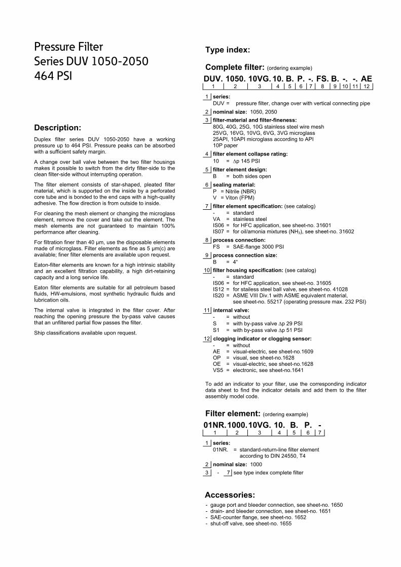
Pressure Filter
Series DUV 1050-2050
464 PSI
Description: Duplex filter series DUV 1050-2050 have a working pressure up to 464 PSI. Pressure peaks can be absorbed with a sufficient safety margin.
A change over ball valve between the two filter housings makes it possible to switch from the dirty filter-side to the clean filter-side without interrupting operation.
The filter element consists of star-shaped, pleated filter material, which is supported on the inside by a perforated core tube and is bonded to the end caps with a high-quality adhesive. The flow direction is from outside to inside.
For cleaning the mesh element or changing the microglasselement, remove the cover and take out the element. The mesh elements are not guaranteed to maintain 100% performance after cleaning.
For filtration finer than 40 μm, use the disposable elements made of microglass. Filter elements as fine as 5 μm(c) are available; finer filter elements are available upon request.
Eaton-filter elements are known for a high intrinsic stability and an excellent filtration capability, a high dirt-retaining capacity and a long service life.
Eaton filter elements are suitable for all petroleum based fluids, HW-emulsions, most synthetic hydraulic fluids and lubrication oils.
The internal valve is integrated in the filter cover. After reaching the opening pressure the by-pass valve causes that an unfiltered partial flow passes the filter.
Ship classifications available upon request.
Type index:
Complete filter: (ordering example)
DUV. 1050. 10VG. 10. B. P. -. FS. B. -. -. AE1 2 3 4 5 6 7 8 9 10 11 12
1 series: DUV = pressure filter, change over with vertical connecting pipe
2 nominal size: 1050, 2050
3 filter-material and filter-fineness: 80G, 40G, 25G, 10G stainless steel wire mesh 25VG, 16VG, 10VG, 6VG, 3VG microglass 25API, 10API microglass according to API 10P paper
4 filter element collapse rating: 10 = p 145 PSI
5 filter element design: B = both sides open
6 sealing material: P = Nitrile (NBR) V = Viton (FPM)
7 filter element specification: (see catalog) - = standard VA = stainless steel IS06 = for HFC application, see sheet-no. 31601 IS07 = for oil/amonia mixtures (NH3), see sheet-no. 31602
8 process connection: FS = SAE-flange 3000 PSI
9 process connection size: B = 4“
10 filter housing specification: (see catalog) - = standard IS06 = for HFC application, see sheet-no. 31605 IS12 = for stailess steel ball valve, see sheet-no. 41028 IS20 = ASME VIII Div.1 with ASME equivalent material,
see sheet-no. 55217 (operating pressure max. 232 PSI)
11 internal valve: - = without S = with by-pass valve p 29 PSI S1 = with by-pass valve p 51 PSI
12 clogging indicator or clogging sensor: - = without AE = visual-electric, see sheet-no.1609 OP = visual, see sheet-no.1628 OE = visual-electric, see sheet-no.1628 VS5 = electronic, see sheet-no.1641
To add an indicator to your filter, use the corresponding indicator data sheet to find the indicator details and add them to the filter assembly model code.
Filter element: (ordering example)
01NR.1000.10VG. 10. B. P. - 1 2 3 4 5 6 7
1 series: 01NR. = standard-return-line filter element
according to DIN 24550, T4
2 nominal size: 1000
3 - 7 see type index complete filter
Accessories:
- gauge port and bleeder connection, see sheet-no. 1650 - drain- and bleeder connection, see sheet-no. 1651 - SAE-counter flange, see sheet-no. 1652 - shut-off valve, see sheet-no. 1655

Technical data:
design temperature: 14 °F to +212 °F operating temperature: 14 °F to +176 °F operating medium mineral oil, other media on request max. operating pressure: 464 PSI max. operating pressure at IS20: 232 PSI test pressure: 900 PSI test pressure at IS20: 464 PSI process connection: SAE-flange 3000 PSI housing material: EN-GJS-400-18-LT switching housing material: S355J2+N sealing material: Nitrile (NBR) or Viton (FPM), other materials on request installation position: vertical measure connections: BSPP ¼ drain- and bleeder connections: BSPP ½ volume tank DUV 1050: 2x 3.6 Gal. DUV 2050: 2x 6.3 Gal.
Classified under the Pressure Equipment Directive 2014/68/EC for mineral oil (fluid group 2), Article 4, Para. 3. Classified under ATEX Directive 2014/34/EC according to specific application (see questionnaire sheet-no. 34279-4).
Pressure drop flow curves:
Filter calculation/sizing
The pressure drop of the assembly at a given flow rate Q is the sum of the housing ∆p and the element ∆p and is calculated as follows:
p assembly = p housing + p element p housing = (see p = f (Q) - characteristics)
p element (PSI) = ,
³
For ease of calculation our Filter Selection tool is available online at www.eatonpowersource.com/calculators/filtration/
Material gradient coefficients (MSK) for filter elements
The material gradient coefficients in psi/gpm apply to mineral oil (HLP) with a density of 0,876 kg/dm³ and a kinematic viscosity of 139 SUS (30 mm²/s). The pressure drop changes proportionally to the change in kinematic viscosity and density.
DUV VG G P API
3VG 6VG 10VG 16VG 25VG 25G 40G 80G 10P 10API 25API
1050 0.237 0.165 0.105 0.092 0.063 0.0061 0.0057 0.0039 0.051 0.053 0.024
2050 0.118 0.082 0.053 0.046 0.031 0.0030 0.0028 0.0019 0.026 0.027 0.012
∆p = f(Q) – characteristics according to ISO 3968
The pressure drop characteristics apply to mineral oil (HLP) with a density of 0,876 kg/dm³. The pressure drop changes proportionally to the density.

Symbols: without indicator with by-pass valve with electric
indicator AE 30 and AE 40
with visual-electric indicator
AE 50 and AE 62
with visual-electric indicator
AE 70 and AE 80
with visual indicator
OP/AOR/AOC
with visual-electrical indicator
OE
with electronic clogging sensor VS5
Spare parts:
item designation qty. dimension and article-no. qty. dimension and article-no. DUV 1050 DUV 2050 1 filter element 2 01NR.1000… 4 01NR.1000… 2 O-ring 4 90 x 4 306941 (NBR) 307031 (FPM) 8 90 x 4 306941 (NBR) 307031 (FPM) 3 O-ring 2 185 x 4 305593 (NBR) 306309 (FPM) 4 185 x 4 305593 (NBR) 306309 (FPM) 4 O-ring 4 114 x 6 314419 (NBR) 316531 (FPM) 4 114 x 6 314419 (NBR) 316531 (FPM) 5 O-ring 4 140 x 4 305145 (NBR) 305201 (FPM) 4 140 x 4 305145 (NBR) 305201 (FPM) 6 screw plug 2 ¼ BSPP 305003 2 ¼ BSPP 305003 7 O-ring 2 54 x 3 304657 (NBR) 304720 (FPM) 2 54 x 3 304657 (NBR) 304720 (FPM) 8 O-ring 2 85,32 x 3,53 305590 (NBR) 306308 (FPM) 2 85,32 x 3,53 305590 (NBR) 306308 (FPM) 9 O-ring 8 8 x 2 310004 (NBR) 316530 (FPM) 8 8 x 2 310004 (NBR) 316530 (FPM) 10 O-ring 4 115 x 5 306640 (NBR) 310287 (FPM) 4 115 x 5 306640 (NBR) 310287 (FPM) 11 screw plug 8 ½ BSPP 304678 10 ½ BSPP 304678 12 slip coupling - - 2 3.543 dia 313233 13 clogging indicator visual 1 OP see sheet-no. 1628 14 clogging indicator visual-electric 1 OE see sheet-no. 1628 15 clogging indicator visual-electric 1 AE see sheet-no. 1609 16 clogging sensor electronic 1 VS5 see sheet-no. 1641 17 O-ring 2 14 x 2 304342 (NBR) 304722 (FPM) 18 screw plug 2 ¼ BSPP 305003 19 gasket 4 DN 90 312275 20 pressure balance valve 1 3/8“ 305000
item 18 execution only without clogging indicator or clogging sensor
Test methods: Filter elements are tested according to the following ISO standards:
ISO 2941 Verification of collapse/burst resistance ISO 2942 Verification of fabrication integrity ISO 2943 Verification of material compatibility with fluids ISO 3723 Method for end load test ISO 3724 Verification of flow fatigue characteristics ISO 3968 Evaluation of pressure drop versus flow characteristics ISO 16889 Multi-pass method for evaluating filtration performance
North America 44 Apple Street Tinton Falls, NJ 07724
Toll Free: 800 656-3344 (North America only)
Tel: +1 732 212-4700 Europe/Africa/Middle East Auf der Heide 2 53947 Nettersheim, Germany
Tel: +49 2486 809-0
Friedensstraße 41 68804 Altlußheim, Germany
Tel: +49 6205 2094-0
An den Nahewiesen 24 55450 Langenlonsheim, Germany
Tel: +49 6704 204-0
China No. 3, Lane 280, Linhong Road Changning District, 200335 Shanghai, P.R. China
Tel: +86 21 5200-0099 Singapore 4 Loyang Lane #04-01/02 Singapore 508914
Tel: +65 6825-1668 Brazil Av. Julia Gaioli, 474 – Bonsucesso 07251-500 – Guarulhos, Brazil
Tel: +55 11 2465-8822
For more information, please email us at [email protected]
or visit www.eaton.com/filtration
© 2015 Eaton. All rights reserved. All trademarks and registered trademarks are the property of their respective owners. All information and recommendations appearing in this brochure concerning the use of products described herein are based on tests believed to be reliable. However, it is the user’s responsibility to determine the suitability for his own use of such products. Since the actual use by others is beyond our control, no guarantee, expressed or implied, is made by Eaton as to the effects of such use or the results to be obtained. Eaton assumes no liability arising out of the use by others of such products. Nor is the information herein to be construed as absolutely complete, since additional information may be necessary or desirable when particular or exceptional conditions or circumstances exist or because of applicable laws or government regulations.

Series DUV 2005-4005
493 PSI
PRESSURE FILTER, change over
Sheet No. 2154 A
EDV 09/15
Position I: Filter 1 in operation Position II: Filter 2 filter-side in operation
1) Connect the stand grounding tab to a suitable earth ground point.
Weight DUV 2005: approx. 750 lbs. Weight DUV 3005: approx. 886 lbs. Weight DUV 4005: approx. 961 lbs. Dimensions: inches Designs and performance values are subject to change.

Pressure Filter
Series DUV 2005-4005
493 PSI
Description: Duplex filter series DUV 1050-2050 have a working pressure up to 493 PSI. Pressure peaks can be absorbed with a sufficient safety margin.
A change over ball valve between the two filter housings makes it possible to switch from the dirty filter-side to the clean filter-side without interrupting operation.
The filter element consists of star-shaped, pleated filter material, which is supported on the inside by a perforated core tube and is bonded to the end caps with a high-quality adhesive. The flow direction is from outside to inside.
For cleaning the mesh element or changing the microglasselement, remove the cover and take out the element. The mesh elements are not guaranteed to maintain 100% performance after cleaning.
For filtration finer than 40 μm, use the disposable elements made of microglass. Filter elements as fine as 5 μm(c) are available; finer filter elements are available upon request.
Eaton-filter elements are known for a high intrinsic stability and an excellent filtration capability, a high dirt-retaining capacity and a long service life.
Eaton filter elements are suitable for all petroleum based fluids, HW-emulsions, most synthetic hydraulic fluids and lubrication oils.
Ship classifications available upon request.
Type index:
Complete filter: (ordering example)
DUV. 2005. 10VG. 10. E. P. -. FS. C. -. AE1 2 3 4 5 6 7 8 9 10 11
1 series: DUV = pressure filter, change over with vertical connecting pipe
2 nominal size: 2005, 3005, 4005
3 filter-material and filter-fineness: 80G, 40G, 25G, 10G stainless steel wire mesh 25VG, 16VG, 10VG, 6VG, 3VG microglass 25API, 10API microglass according to API 10P paper
4 filter element collapse rating: 10 = p 145 PSI
5 filter element design: E = single end open S = with by-pass valve p 29 PSI
6 sealing material: P = Nitrile (NBR) V = Viton (FPM)
7 filter element specification: (see catalog) - = standard VA = stainless steel IS06 = for HFC application, see sheet-no. 31601
8 process connection: FS = SAE-flange 3000 PSI
9 process connection size: C = 5“
10 filter housing specification: (see catalog) - = standard IS06 = for HFC application, see sheet-no. 31605 IS12 = for stailess steel ball valve, see sheet-no. 41028 IS20 = ASME VIII Div.1 with ASME equivalent material,
see sheet-no. 55217 (operating pressure max. 232 PSI)
11 clogging indicator or clogging sensor: - = without AOR = visual, see sheet-no.1606 AOC = visual, see sheet-no.1606 AE = visual-electric, see sheet-no.1609 OP = visual, see sheet-no.1628 OE = visual-electric, see sheet-no.1628 VS5 = electronic, see sheet-no.1641
To add an indicator to your filter, use the corresponding indicator data sheet to find the indicator details and add them to the filter assembly model code.
Filter element: (ordering example)
01E. 2001.10VG. 10. E. P. - 1 2 3 4 5 6 7
1 series: 01E. = filter element according to company standard
2 nominal size: 2001, 3001, 4001
3 - 7 see type index complete filter
Accessories:
- gauge port and bleeder connection, see sheet-no. 1650 - drain- and bleeder connection, see sheet-no. 1651 - SAE-counter flange, see sheet-no. 1652 - shut-off valve, see sheet-no. 1655

Technical data:
design temperature: 14 °F to +212 °F operating temperature: 14 °F to +176 °F operating medium mineral oil, other media on request max. operating pressure: 493 PSI max. operating pressure at IS20: 232 PSI test pressure: 986 PSI test pressure at IS20: 464 PSI process connection: SAE-flange 3000 PSI housing material: EN-GJS-400-18-LT switching housing material: S355J2+N sealing material: Nitrile (NBR) or Viton (FPM), other materials on request installation position: vertical measure connections: BSPP ¼ drain- and bleeder connections: BSPP ½ volume tank DUV 2005: 2x 8 Gal. DUV 3005: 2x 10 Gal. DUV 4005 2x 12 Gal.
Classified under the Pressure Equipment Directive 2014/68/EC for mineral oil (fluid group 2), Article 4, Para. 3. Classified under ATEX Directive 2014/34/EC according to specific application (see questionnaire sheet-no. 34279-4).
Pressure drop flow curves:
Filter calculation/sizing
The pressure drop of the assembly at a given flow rate Q is the sum of the housing ∆p and the element ∆p and is calculated as follows:
p assembly = p housing + p element p housing = (see p = f (Q) - characteristics)
p element (PSI) = ,
³
For ease of calculation our Filter Selection tool is available online at www.eatonpowersource.com/calculators/filtration/
Material gradient coefficients (MSK) for filter elements
The material gradient coefficients in psi/gpm apply to mineral oil (HLP) with a density of 0,876 kg/dm³ and a kinematic viscosity of 139 SUS (30 mm²/s). The pressure drop changes proportionally to the change in kinematic viscosity and density.
DUV VG G P API
3VG 6VG 10VG 16VG 25VG 25G 40G 80G 10P 10API 25API
2005 0.177 0.123 0.079 0.068 0.047 0.0059 0.0055 0.0038 0.041 0.040 0.018
3005 0.118 0.082 0.052 0.046 0.031 0.0040 0.0037 0.0025 0.027 0.027 0.012
4005 0.088 0.061 0.039 0.034 0.023 0.0030 0.0028 0.0019 0.020 0.020 0.009
∆p = f(Q) – characteristics according to ISO 3968
The pressure drop characteristics apply to mineral oil (HLP) with a density of 0,876 kg/dm³. The pressure drop changes proportionally to the density.

Symbols: without indicator with by-pass valve with electric
indicator AE 30 and AE 40
with visual-electric indicator
AE 50 and AE 62
with visual-electric indicator
AE 70 and AE 80
with visual indicator
OP/AOR/AOC
with visual-electrical indicator
OE
with electronic clogging sensor VS5
Spare parts:
item qty. designation dimension and article-no.
dimension and article-no.
dimension and article-no.
DUV 2005 DUV 3005 DUV 4005 1 2 filter element 01E.2001… 01E.3001… 01E.4001… 2 1 gasket kit of change over 5“ 322726 (NBR) 322727 (FPM) 3 2 O-ring (DU 2005) 240 x 5 307592 (NBR) 328793 (FPM) 4 O-ring (DU 3005/4005)
4 2 O-ring 135 x 10 306016 (NBR) 307045 (FPM) 5 2 O-ring 125 x 10 304388 (NBR) 306006 (FPM) 6 2 O-ring 136,12 x 3,53 320162 (NBR) 320163 (FPM) 7 8 screw plug (DU 2005) BSPP ½ 304678 10 screw plug (DU 3005/4005)
8 1 clogging indicator visual AOR or AOC see seet-no. 1606 9 1 clogging indicator visual-electric OE see seet-no. 1628 10 1 clogging indicator visual OP see seet-no. 1628 11 1 clogging indicator visual-electric AE see seet-no. 1609 12 1 clogging sensor electronic VS5 see seet-no. 1641 13 1 O-ring 15 x 1,5 315357 (NBR) 315427 (FPM) 14 1 O-ring 22 x 2 304708 (NBR) 304721 (FPM) 15 2 O-ring 14 x 2 304342 (NBR) 304722 (FPM) 16 2 screw plug BSPP ¼ 305003 17 1 pressure balance valve 3/8“ 305000
item 16 execution only without clogging indicator or clogging sensor
Test methods: Filter elements are tested according to the following ISO standards:
ISO 2941 Verification of collapse/burst resistance ISO 2942 Verification of fabrication integrity ISO 2943 Verification of material compatibility with fluids ISO 3723 Method for end load test ISO 3724 Verification of flow fatigue characteristics ISO 3968 Evaluation of pressure drop versus flow characteristics ISO 16889 Multi-pass method for evaluating filtration performance
North America 44 Apple Street Tinton Falls, NJ 07724
Toll Free: 800 656-3344 (North America only)
Tel: +1 732 212-4700 Europe/Africa/Middle East Auf der Heide 2 53947 Nettersheim, Germany
Tel: +49 2486 809-0
Friedensstraße 41 68804 Altlußheim, Germany
Tel: +49 6205 2094-0
An den Nahewiesen 24 55450 Langenlonsheim, Germany
Tel: +49 6704 204-0
China No. 3, Lane 280, Linhong Road Changning District, 200335 Shanghai, P.R. China
Tel: +86 21 5200-0099 Singapore 4 Loyang Lane #04-01/02 Singapore 508914
Tel: +65 6825-1668 Brazil Av. Julia Gaioli, 474 – Bonsucesso 07251-500 – Guarulhos, Brazil
Tel: +55 11 2465-8822
For more information, please email us at [email protected]
or visit www.eaton.com/filtration
© 2015 Eaton. All rights reserved. All trademarks and registered trademarks are the property of their respective owners. All information and recommendations appearing in this brochure concerning the use of products described herein are based on tests believed to be reliable. However, it is the user’s responsibility to determine the suitability for his own use of such products. Since the actual use by others is beyond our control, no guarantee, expressed or implied, is made by Eaton as to the effects of such use or the results to be obtained. Eaton assumes no liability arising out of the use by others of such products. Nor is the information herein to be construed as absolutely complete, since additional information may be necessary or desirable when particular or exceptional conditions or circumstances exist or because of applicable laws or government regulations.

Series MDD 40-63
2900 PSI
PRESSURE FILTER, change over
Sheet No. 2516 F
EDV 09/15
1) Connect the stand grounding tab to a suitable earth ground point.
Dimensions: inches Designs and performance values are subject to change.
Dimensions:
type MDD 40 MDD 63 connection - 8 SAE -12 SAE
A 8.11 10.47 B 11.22 13.58
weight approx. 34 lbs. 36 lbs. volume tank 2x .06 Gal. 2x .09 Gal.
Position. I: left filter-side in operation Position. II: right filter-side in operation
Connection V and VI should be used to bleed filter or to relieve pressure.

Pressure Filter
Series MDD 40-63
2900 PSI
Description: Duplex pressure filter series MDD 40-63 with change-over valve have a working pressure up to 2900 PSI. Pressure peaks can be absorbed with a sufficient safety margin. Duplex filters can be serviced without interruption of operation.
The filter head has a three-way-change-over valve which diverts the flow from the dirty filter-side to the clean filter-side without interrupting operation of the filter. All filter housings have an integrated pressure balance valve to make main valve operation from one filter side to the other easier. Filter elements are available down to 5 µm(c). Finer filtration is available upon request.
Eaton filter elements are known for high intrinsic stability and an excellent filtration capability, a high dirt-retaining capacity and a long service life.
Eaton filter elements are suitable for all petroleum based fluids, HW-emulsions, most synthetic hydraulic fluids and lubrication oils.
Eaton filter elements are available up to a pressure resistance of p 2320 PSI and a rupture strength ofp 3625 PSI.
The internal valve is integrated into the filter head. After reaching the bypass pressure setting, the bypass valve will send unfiltered partial flow around the filter. The reversing valve provides another level of protection for the filter element. The reverse flow will not be filtered.
1. Type index:
1.1. Complete filter: (ordering example)
MDD. 40. 10VG. HR. E. P. -. UG. 3. -. -. AE1 2 3 4 5 6 7 8 9 10 11 12
1 series: MDD = medium pressure filter, change over
2 nominal size: 40, 63
3 filter-material and filter-fineness: 25VG, 16VG, 10VG, 6VG, 3VG microglass
4 filter element collapse rating: 30 = p 435 PSI HR = p 2320 PSI (rupture strength p 3625 PSI)
5 filter element design: E = single-end open
6 sealing material: P = Nitrile (NBR) V = Viton (FPM)
7 filter element specification: (see catalog) - = standard VA = stainless steel IS06 = for HFC applications, see sheet-no. 31601
8 process connection: UG = thread connection
9 process connection size: 3 = -8 SAE (MDD 40) 4 = -12 SAE (MDD 63)
10 filter housing specification: (see catalog) - = standard IS06 = for HFC applications, see sheet-no. 31605 IS12 = for stainless steel ball valve, see sheet-no. 41028
11 internal valve: - = without S1 = with by-pass valve p 51 PSI S2 = with by-pass valve p 102 PSI R = reversing valve, Q ≤ 18.50 GPM
12 clogging indicator or clogging sensor: - = without AOR = visual, see sheet-no. 1606 AOC = visual, see sheet-no. 1606 AE = visual-electric, see sheet-no. 1615 VS5 = electronic, see sheet-no. 1619
To add an indicator to your filter, use the corresponding indicator data sheet to find the indicator details and add them to the filter assembly model code.
1.2. Filter element: (ordering example)
01NL. 40. 10VG. HR. E. P. - 1 2 3 4 5 6 7
1 series: 01NL. = standard filter element according to DIN 24550, T3
2 nominal size: 40, 63
3 - 7 see type index-complete filter
Accessories:
- gauge port- and bleeder connection, see sheet-no. 1650
.

Technical data:
design temperature: 14 °F to +212 °F operating temperature: 14 °F to +176 °F operating medium mineral oil, other media on request max. operating pressure: 2900 PSI test pressure: 4147 PSI process connection: thread connection housing material: C-steel sealing material: Nitrile (NBR) or Viton (FPM), other materials on request installation position: vertical air bleeding and measure connections dirt side: BSPP ¼ measure connections clean side: BSPP ½
Classified under the Pressure Equipment Directive 2014/68/EC for mineral oil (fluid group 2), Article 4, Para. 3. Classified under ATEX Directive 2014/34/EC according to specific application (see questionnaire sheet-no. 34279-4).
Pressure drop flow curves:
Filter calculation/sizing
The pressure drop of the assembly at a given flow rate Q is the sum of the housing ∆p and the element ∆p and is calculated as follows:
p assembly = p housing + p element p housing = (see p = f (Q) - characteristics)
p element (PSI) = .
³
For ease of calculation our Filter Selection tool is available online at www.eatonpowersource.com/calculators/filtration/
Material gradient coefficients (MSK) for filter elements
The material gradient coefficients in PSI/GPM apply to mineral oil (HLP) with a density of 0.876 kg/dm³ and a kinematic viscosity of 139 SUS (30 mm²/s). The pressure drop changes proportionally to the change in kinematic viscosity and density.
MDD VG
3VG 6VG 10VG 16VG 25VG
40 6.991 4.853 3.107 2.705 1.848
63 4.214 2.926 1.873 1.631 1.114
∆p = f(Q) – characteristics according to ISO 3968
The pressure drop characteristics apply to mineral oil (HLP) with a density of 0.876 kg/dm³. The pressure drop changes proportionally to the density.

Symbols:
without indicator with electric indicator
AE 30 and AE 40
with visual-electric indicator
AE 50 and AE 62
with visual-electric indicator
AE 70 and AE 80
with visual indicator
AOR/AOC
with electronic clogging sensor
VS5 filter without internal valve
filter with by-pass valve
filter with reversing valve
Spare parts:
item qty. designation dimension article-no. MDD 40 MDD 63
1 2 filter element 01NL.40… 01NL.63… 2 2 O-ring 22 x 3,5 304341 (NBR) 304392 (FPM) 3 2 O-ring 54 x 3 304657 (NBR) 304720 (FPM) 4 2 support ring 60 x 2,6 x 1 311779 5 3 O-ring 26 x 3 304379 (NBR) 318576 (FPM) 6 4 O-ring 28 x 3 316778 (NBR) 318366 (FPM) 7 4 O-ring 18 x 3 304359 (NBR) 304399 (FPM) 8 4 O-ring 6,5 x 2 313553 (NBR) 318577 (FPM) 9 2 screw plug ½ BSPP 304678
10 2 screw plug ¼ BSPP 305003 11 1 clogging indicator, visual AOR or AOC see sheet-no. 1606 12 1 clogging indicator, visual-electric AE see sheet-no. 1615 13 1 clogging sensor, electronic VS5 see sheet-no. 1619 14 1 O-ring 15 x 1,5 315357 (NBR) 315427 (FPM) 15 1 O-ring 22 x 2 304708 (NBR) 304721 (FPM) 16 1 O-ring 14 x 2 304342 (NBR) 304722 (FPM) 17 1 screw plug 20913-4 309817 18 1 pressure balance valve 3/8“ 305000
item 17 execution only without clogging indicator or clogging sensor
Test methods: Filter elements are tested according to the following ISO standards:
ISO 2941 Verification of collapse/burst resistance ISO 2942 Verification of fabrication integrity ISO 2943 Verification of material compatibility with fluids ISO 3723 Method for end load test ISO 3724 Verification of flow fatigue characteristics ISO 3968 Evaluation of pressure drop versus flow characteristics ISO 16889 Multi-pass method for evaluating filtration performance
North America 44 Apple Street Tinton Falls, NJ 07724
Toll Free: 800 656-3344 (North America only)
Tel: +1 732 212-4700 Europe/Africa/Middle East Auf der Heide 2 53947 Nettersheim, Germany
Tel: +49 2486 809-0
Friedensstraße 41 68804 Altlußheim, Germany
Tel: +49 6205 2094-0
An den Nahewiesen 24 55450 Langenlonsheim, Germany
Tel: +49 6704 204-0
China No. 3, Lane 280, Linhong Road Changning District, 200335 Shanghai, P.R. China
Tel: +86 21 5200-0099 Singapore 4 Loyang Lane #04-01/02 Singapore 508914
Tel: +65 6825-1668 Brazil Av. Julia Gaioli, 474 – Bonsucesso 07251-500 – Guarulhos, Brazil
Tel: +55 11 2465-8822
For more information, please email us at [email protected]
or visit www.eaton.com/filtration
© 2015 Eaton. All rights reserved. All trademarks and registered trademarks are the property of their respective owners. All information and recommendations appearing in this brochure concerning the use of products described herein are based on tests believed to be reliable. However, it is the user’s responsibility to determine the suitability for his own use of such products. Since the actual use by others is beyond our control, no guarantee, expressed or implied, is made by Eaton as to the effects of such use or the results to be obtained. Eaton assumes no liability arising out of the use by others of such products. Nor is the information herein to be construed as absolutely complete, since additional information may be necessary or desirable when particular or exceptional conditions or circumstances exist or because of applicable laws or government regulations.
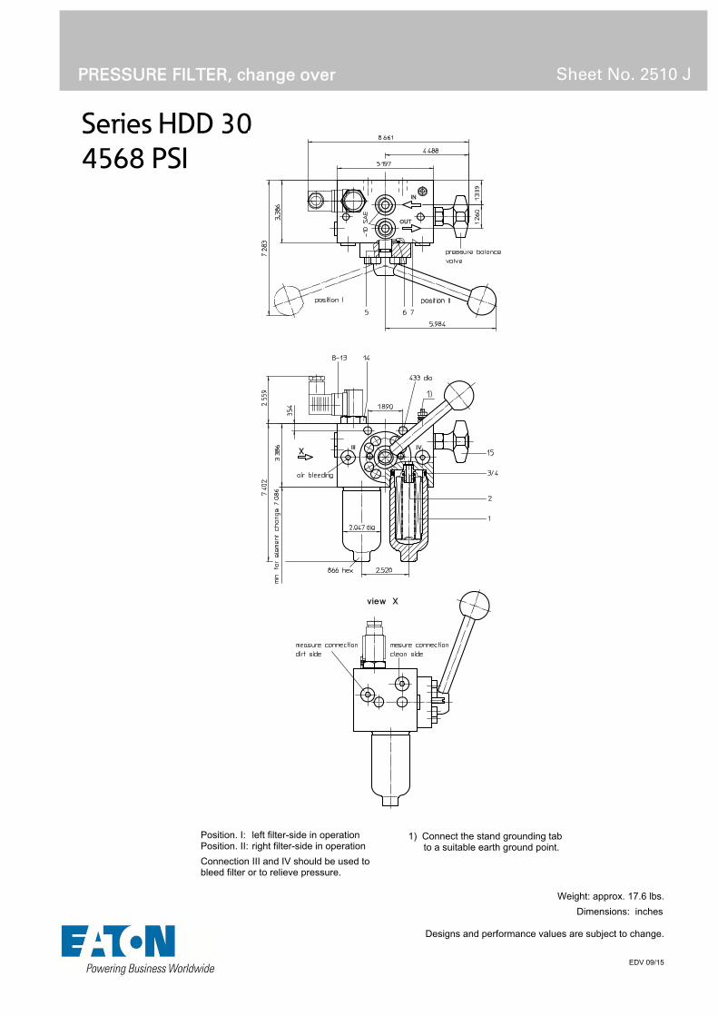
Series HDD 30
4568 PSI
PRESSURE FILTER, change over
Sheet No. 2510 J
EDV 09/15
1) Connect the stand grounding tab to a suitable earth ground point.
Weight: approx. 17.6 lbs.
Dimensions: inches Designs and performance values are subject to change.
Position. I: left filter-side in operation Position. II: right filter-side in operation
Connection III and IV should be used to bleed filter or to relieve pressure.

Pressure Filter
Series HDD 30
4568 PSI
Description: Duplex pressure filter series HDD 30 with change-over valve have a working pressure up to 4568 PSI. Pressure peaks can be absorbed with a sufficient safety margin. Duplex filters can be serviced without interruption of operation.
The filter head has a three-way-change-over valve which diverts the flow from the dirty filter-side to the clean filter-side without interrupting operation of the filter. All filter housings have an integrated pressure balance valve to make main valve operation from one filter side to the other easier. Filter elements are available down to 5 µm(c). Finer filtration is available upon request.
Eaton filter elements are known for high intrinsic stability and an excellent filtration capability, a high dirt-retaining capacity and a long service life.
Eaton filter elements are suitable for all petroleum based fluids, HW-emulsions, most synthetic hydraulic fluids and lubrication oils.
Eaton filter elements are available up to a pressure resistance of p 2320 PSI and a rupture strength ofp 3625 PSI.
1. Type index:
1.1. Complete filter: (ordering example)
HDD. 30. 10VG. HR. E. P. -. UG. 3A. -. AE1 2 3 4 5 6 7 8 9 10 11
1 series: HDD = pressure filter, change over
2 nominal size: 30
3 filter-material and filter-fineness: 25VG, 16VG, 10VG, 6VG, 3VG microglass
4 filter element collapse rating: 30 = p 435 PSI HR = p 2320 PSI (rupture strength p 3625 PSI)
5 filter element design: E = single-end open
6 sealing material: P = Nitrile (NBR) V = Viton (FPM)
7 filter element specification: - = standard VA = stainless steel
8 process connection: UG = thread connection
9 process connection size: 3A = -10 SAE
10 filter housing specification: - = standard
11 clogging indicator or clogging sensor: - = without AOR = visual, see sheet-no. 1606 AOC = visual, see sheet-no. 1606 AE = visual-electric, see sheet-no. 1615 VS5 = electronic, see sheet-no. 1619
To add an indicator to your filter, use the corresponding indicator data sheet to find the indicator details and add them to the filter assembly model code.
1.2. Filter element: (ordering example)
01E. 30. 10VG. HR. E. P. - 1 2 3 4 5 6 7
1 series: 01E. = filter element according to company standard
2 nominal size: 30
3 - 7 see type index-complete filter
Accessories:
- gauge port- and bleeder connection, see sheet-no. 1650
.

Technical data:
design temperature: 14 °F to +212 °F operating temperature: 14 °F to +176 °F operating medium mineral oil, other media on request max. operating pressure: 4568 PSI test pressure: 6525 PSI process connection: thread connection housing material: EN-GJS-400-18-LT, C-steel sealing material: Nitrile (NBR) or Viton (FPM), other materials on request installation position: vertical air bleeding and measure connections dirt side: BSPP ¼ measure connections clean side: BSPP ½
Classified under the Pressure Equipment Directive 2014/68/EC for mineral oil (fluid group 2), Article 4, Para. 3. Classified under ATEX Directive 2014/34/EC according to specific application (see questionnaire sheet-no. 34279-4).
Pressure drop flow curves:
Filter calculation/sizing
The pressure drop of the assembly at a given flow rate Q is the sum of the housing ∆p and the element ∆p and is calculated as follows:
p assembly = p housing + p element p housing = (see p = f (Q) - characteristics)
p element (PSI) = .
³
For ease of calculation our Filter Selection tool is available online at www.eatonpowersource.com/calculators/filtration/
Material gradient coefficients (MSK) for filter elements
The material gradient coefficients in PSI/GPM apply to mineral oil (HLP) with a density of 0.876 kg/dm³ and a kinematic viscosity of 139 SUS (30 mm²/s). The pressure drop changes proportionally to the change in kinematic viscosity and density.
HDD VG
3VG 6VG 10VG 16VG 25VG
30 12.554 8.716 5.580 4.794 3.275
∆p = f(Q) – characteristics according to ISO 3968
The pressure drop characteristics apply to mineral oil (HLP) with a density of 0.876 kg/dm³. The pressure drop changes proportionally to the density.

Symbols:
without indicator with electric indicator
AE 30 and AE 40
with visual-electric indicator
AE 50 and AE 62
with visual-electric indicator
AE 70 and AE 80
with visual indicator
AOR/AOC
with electronic clogging sensor
VS5
Spare parts:
item qty. designation dimension article-no. 1 2 filter element 01E.30... 2 2 O-ring 12,37 x 2,62 304356 (NBR) 304396 (FPM) 3 2 O-ring 40 x 3 304389 (NBR) 304391 (FPM) 4 2 support ring 48 x 2,6 x 1 305391 5 2 O-ring 10 x 3 307285 (NBR) 311019 (FPM) 6 2 O-ring 32 x 3 304368 (NBR) 311020 (FPM) 7 4 screw plug ¼ BSPP 305003 8 1 clogging indicator, visual AOR or AOC see sheet-no. 1606 9 1 clogging indicator, visual-electric AE see sheet-no. 1615
10 1 clogging sensor, electronic VS5 see sheet-no. 1619 11 1 O-ring 15 x 1,5 315357 (NBR) 315427 (FPM) 12 1 O-ring 22 x 2 304708 (NBR) 304721 (FPM) 13 1 O-ring 14 x 2 304342 (NBR) 304722 (FPM) 14 1 screw plug 20913-4 309817 15 1 pressure balance valve 3/8“ 305000
item 14 execution only without clogging indicator or clogging sensor
Test methods: Filter elements are tested according to the following ISO standards:
ISO 2941 Verification of collapse/burst resistance ISO 2942 Verification of fabrication integrity ISO 2943 Verification of material compatibility with fluids ISO 3723 Method for end load test ISO 3724 Verification of flow fatigue characteristics ISO 3968 Evaluation of pressure drop versus flow characteristics ISO 16889 Multi-pass method for evaluating filtration performance
North America 44 Apple Street Tinton Falls, NJ 07724
Toll Free: 800 656-3344 (North America only)
Tel: +1 732 212-4700 Europe/Africa/Middle East Auf der Heide 2 53947 Nettersheim, Germany
Tel: +49 2486 809-0
Friedensstraße 41 68804 Altlußheim, Germany
Tel: +49 6205 2094-0
An den Nahewiesen 24 55450 Langenlonsheim, Germany
Tel: +49 6704 204-0
China No. 3, Lane 280, Linhong Road Changning District, 200335 Shanghai, P.R. China
Tel: +86 21 5200-0099 Singapore 4 Loyang Lane #04-01/02 Singapore 508914
Tel: +65 6825-1668 Brazil Av. Julia Gaioli, 474 – Bonsucesso 07251-500 – Guarulhos, Brazil
Tel: +55 11 2465-8822
For more information, please email us at [email protected]
or visit www.eaton.com/filtration
© 2015 Eaton. All rights reserved. All trademarks and registered trademarks are the property of their respective owners. All information and recommendations appearing in this brochure concerning the use of products described herein are based on tests believed to be reliable. However, it is the user’s responsibility to determine the suitability for his own use of such products. Since the actual use by others is beyond our control, no guarantee, expressed or implied, is made by Eaton as to the effects of such use or the results to be obtained. Eaton assumes no liability arising out of the use by others of such products. Nor is the information herein to be construed as absolutely complete, since additional information may be necessary or desirable when particular or exceptional conditions or circumstances exist or because of applicable laws or government regulations.

Series HDD 61-151
4568 PSI
PRESSURE FILTER, change over
Sheet No. 2517 F
EDV 09/15
1) Connect the stand grounding tab to a suitable earth ground point.
Dimensions: inches Designs and performance values are subject to change.
Position. I: left filter-side in operation Position. II: right filter-side in operation
Connection V and VI should be used to bleed filter or to relieve pressure.
Dimensions:
type HDD 61 HDD 91 HDD 151 connection -16 SAE
A 8.97 11.53 15.82 B 10.82 13.38 17.71
weight approx. 53 lbs. 55 lbs. 59 lbs. volume tank 2x .08 Gal. 2x .10 Gal. 2x .16 Gal.
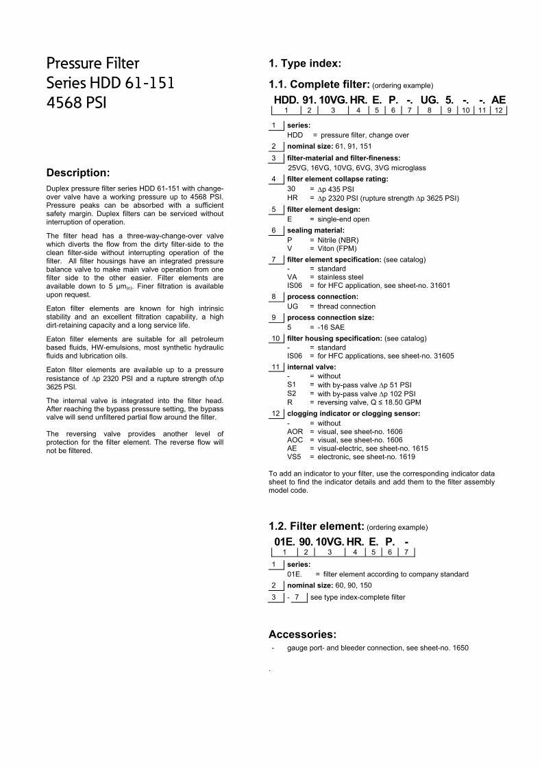
Pressure Filter
Series HDD 61-151
4568 PSI
Description: Duplex pressure filter series HDD 61-151 with change-over valve have a working pressure up to 4568 PSI. Pressure peaks can be absorbed with a sufficient safety margin. Duplex filters can be serviced without interruption of operation.
The filter head has a three-way-change-over valve which diverts the flow from the dirty filter-side to the clean filter-side without interrupting operation of the filter. All filter housings have an integrated pressure balance valve to make main valve operation from one filter side to the other easier. Filter elements are available down to 5 µm(c). Finer filtration is available upon request.
Eaton filter elements are known for high intrinsic stability and an excellent filtration capability, a high dirt-retaining capacity and a long service life.
Eaton filter elements are suitable for all petroleum based fluids, HW-emulsions, most synthetic hydraulic fluids and lubrication oils.
Eaton filter elements are available up to a pressure resistance of p 2320 PSI and a rupture strength ofp 3625 PSI.
The internal valve is integrated into the filter head. After reaching the bypass pressure setting, the bypass valve will send unfiltered partial flow around the filter. The reversing valve provides another level of protection for the filter element. The reverse flow will not be filtered.
1. Type index:
1.1. Complete filter: (ordering example)
HDD. 91. 10VG. HR. E. P. -. UG. 5. -. -. AE1 2 3 4 5 6 7 8 9 10 11 12
1 series: HDD = pressure filter, change over
2 nominal size: 61, 91, 151
3 filter-material and filter-fineness: 25VG, 16VG, 10VG, 6VG, 3VG microglass
4 filter element collapse rating: 30 = p 435 PSI HR = p 2320 PSI (rupture strength p 3625 PSI)
5 filter element design: E = single-end open
6 sealing material: P = Nitrile (NBR) V = Viton (FPM)
7 filter element specification: (see catalog) - = standard VA = stainless steel IS06 = for HFC application, see sheet-no. 31601
8 process connection: UG = thread connection
9 process connection size: 5 = -16 SAE
10 filter housing specification: (see catalog) - = standard IS06 = for HFC applications, see sheet-no. 31605
11 internal valve: - = without S1 = with by-pass valve p 51 PSI S2 = with by-pass valve p 102 PSI R = reversing valve, Q ≤ 18.50 GPM
12 clogging indicator or clogging sensor: - = without AOR = visual, see sheet-no. 1606 AOC = visual, see sheet-no. 1606 AE = visual-electric, see sheet-no. 1615 VS5 = electronic, see sheet-no. 1619
To add an indicator to your filter, use the corresponding indicator data sheet to find the indicator details and add them to the filter assembly model code.
1.2. Filter element: (ordering example)
01E. 90. 10VG. HR. E. P. - 1 2 3 4 5 6 7
1 series: 01E. = filter element according to company standard
2 nominal size: 60, 90, 150
3 - 7 see type index-complete filter
Accessories:
- gauge port- and bleeder connection, see sheet-no. 1650
.

Technical data:
design temperature: 14 °F to +212 °F operating temperature: 14 °F to +176 °F operating medium mineral oil, other media on request max. operating pressure: 4538 PSI test pressure: 6525 PSI process connection: thread connection housing material: C-steel sealing material: Nitrile (NBR) or Viton (FPM), other materials on request installation position: vertical air bleeding and measure connections dirt side: BSPP ¼ measure connections clean side: BSPP ¾
Classified under the Pressure Equipment Directive 2014/68/EC for mineral oil (fluid group 2), Article 4, Para. 3. Classified under ATEX Directive 2014/34/EC according to specific application (see questionnaire sheet-no. 34279-4).
Pressure drop flow curves:
Filter calculation/sizing
The pressure drop of the assembly at a given flow rate Q is the sum of the housing ∆p and the element ∆p and is calculated as follows:
p assembly = p housing + p element p housing = (see p = f (Q) - characteristics)
p element (PSI) = .
³
For ease of calculation our Filter Selection tool is available online at www.eatonpowersource.com/calculators/filtration/
Material gradient coefficients (MSK) for filter elements
The material gradient coefficients in PSI/GPM apply to mineral oil (HLP) with a density of 0.876 kg/dm³ and a kinematic viscosity of 139 SUS (30 mm²/s). The pressure drop changes proportionally to the change in kinematic viscosity and density.
HDD VG
3VG 6VG 10VG 16VG 25VG
61 6.748 4.685 2.999 2.577 1.760
91 4.059 2.818 1.804 1.550 1.059
151 2.422 1.681 1.076 0.925 0.632
∆p = f(Q) – characteristics according to ISO 3968
The pressure drop characteristics apply to mineral oil (HLP) with a density of 0.876 kg/dm³. The pressure drop changes proportionally to the density.

Symbols:
without indicator with electric indicator
AE 30 and AE 40
with visual-electric indicator
AE 50 and AE 62
with visual-electric indicator
AE 70 and AE 80
with visual indicator
AOR/AOC
with electronic clogging sensor
VS5 filter without internal valve
filter with by-pass valve
filter with reversing valve
Spare parts:
item qty. designation dimension article-no. HDD 61 HDD 91 HDD 151
1 2 filter element 01E.60… 01E.90… 01E.150… 2 2 O-ring 22 x 3,5 304341 (NBR) 304392 (FPM) 3 2 O-ring 54 x 3 304657 (NBR) 304720 (FPM) 4 2 support ring 61 x 2,6 x 1 304660 5 3 O-ring 45 x 3 304991 (NBR) 304997 (FPM) 6 2 support ring 49,7 x 2,4 x 1 317709 7 4 O-ring 38 x 3 304340 (NBR) 317013 (FPM) 8 4 O-ring 28 x 3 316778 (NBR) 318366 (FPM) 9 4 O-ring 8 x 2 310004 (NBR) 316530 (FPM)
10 2 screw plug ¾ BSPP 308529 11 2 screw plug ¼ BSPP 305003 12 1 clogging indicator, visual AOR or AOC see sheet-no. 1606 13 1 clogging indicator, visual-electric AE see sheet-no. 1615 14 1 clogging sensor, electronic VS5 see sheet-no. 1619 15 1 O-ring 15 x 1,5 315357 (NBR) 315427 (FPM) 16 1 O-ring 22 x 2 304708 (NBR) 304721 (FPM) 17 1 O-ring 14 x 2 304342 (NBR) 304722 (FPM) 18 1 screw plug 20913-4 309817 19 1 pressure balance valve 3/8“ 305000
item 18 execution only without clogging indicator or clogging sensor
Test methods: Filter elements are tested according to the following ISO standards:
ISO 2941 Verification of collapse/burst resistance ISO 2942 Verification of fabrication integrity ISO 2943 Verification of material compatibility with fluids ISO 3723 Method for end load test ISO 3724 Verification of flow fatigue characteristics ISO 3968 Evaluation of pressure drop versus flow characteristics ISO 16889 Multi-pass method for evaluating filtration performance
North America 44 Apple Street Tinton Falls, NJ 07724
Toll Free: 800 656-3344 (North America only)
Tel: +1 732 212-4700 Europe/Africa/Middle East Auf der Heide 2 53947 Nettersheim, Germany
Tel: +49 2486 809-0
Friedensstraße 41 68804 Altlußheim, Germany
Tel: +49 6205 2094-0
An den Nahewiesen 24 55450 Langenlonsheim, Germany
Tel: +49 6704 204-0
China No. 3, Lane 280, Linhong Road Changning District, 200335 Shanghai, P.R. China
Tel: +86 21 5200-0099 Singapore 4 Loyang Lane #04-01/02 Singapore 508914
Tel: +65 6825-1668 Brazil Av. Julia Gaioli, 474 – Bonsucesso 07251-500 – Guarulhos, Brazil
Tel: +55 11 2465-8822
For more information, please email us at [email protected]
or visit www.eaton.com/filtration
© 2015 Eaton. All rights reserved. All trademarks and registered trademarks are the property of their respective owners. All information and recommendations appearing in this brochure concerning the use of products described herein are based on tests believed to be reliable. However, it is the user’s responsibility to determine the suitability for his own use of such products. Since the actual use by others is beyond our control, no guarantee, expressed or implied, is made by Eaton as to the effects of such use or the results to be obtained. Eaton assumes no liability arising out of the use by others of such products. Nor is the information herein to be construed as absolutely complete, since additional information may be necessary or desirable when particular or exceptional conditions or circumstances exist or because of applicable laws or government regulations.

Series HDD 170-450
4568 PSI
PRESSURE FILTER, change over
Sheet No. 2514 R
EDV 09/15
1) Connect the stand grounding tab to a suitable earth ground point.
Dimensions: inches Designs and performance values are subject to change.
Position. I: left filter-side in operation Position. II: right filter-side in operation
Connection III and IV should be used to bleed filter or to relieve pressure.
Dimensions:
type HDD 170 HDD 240 HDD 360 HDD 450 connection SAE 1 ½“
A 14.96 16.93 20.08 24.21 B 7.48 9.45 12.60 16.73 C 13.78 15.75 18.90 23.03
weight approx. 86 lbs. 90 lbs. 99 lbs. 110 lbs. volume tank 2x .18 Gal. 2x .23 Gal. 2x .31 Gal. 2x .42 Gal.

Pressure Filter
Series HDD 170-450
4568 PSI
Description: Duplex pressure filter series HDD 170-450 with change-over valve have a working pressure up to 4568 PSI. Pressure peaks can be absorbed with a sufficient safety margin. Duplex filters can be serviced without interruption of operation.
The filter head has a three-way-change-over valve which diverts the flow from the dirty filter-side to the clean filter-side without interrupting operation of the filter. All filter housings have an integrated pressure balance valve to make main valve operation from one filter side to the other easier. Filter elements are available down to 5 µm(c). Finer filtration is available upon request.
Eaton filter elements are known for high intrinsic stability and an excellent filtration capability, a high dirt-retaining capacity and a long service life.
Eaton filter elements are suitable for all petroleum based fluids, HW-emulsions, most synthetic hydraulic fluids and lubrication oils.
Eaton filter elements are available up to a pressure resistance of p 2320 PSI and a rupture strength ofp 3625 PSI.
The internal valve is integrated into the filter head. After reaching the bypass pressure setting, the bypass valve will send unfiltered partial flow around the filter. The reversing valve provides another level of protection for the filter element. The reverse flow will not be filtered.
1. Type index:
1.1. Complete filter: (ordering example)
HDD. 170.10VG. HR. E. P. -. FS. 7. -. -. AE1 2 3 4 5 6 7 8 9 10 11 12
1 series: HDD = pressure filter, change over
2 nominal size: 170, 240, 360, 450
3 filter-material and filter-fineness: 25VG, 16VG, 10VG, 6VG, 3VG microglass
4 filter element collapse rating: 30 = p 435 PSI HR = p 2320 PSI (rupture strength p 3625 PSI)
5 filter element design: E = single-end open
6 sealing material: P = Nitrile (NBR) V = Viton (FPM)
7 filter element specification: - = standard VA = stainless steel
8 process connection: FS = SAE-flange 6000 PSI
9 process connection size: 7 = 1 ½“
10 filter housing specification: - = standard
11 internal valve: - = without S1 = with by-pass valve p 51 PSI S2 = with by-pass valve p 102 PSI R = reversing valve, Q ≤ 55.75 GPM
12 clogging indicator or clogging sensor: - = without AOR = visual, see sheet-no. 1606 AOC = visual, see sheet-no. 1606 AE = visual-electric, see sheet-no. 1615 VS5 = electronic, see sheet-no. 1619
To add an indicator to your filter, use the corresponding indicator data sheet to find the indicator details and add them to the filter assembly model code.
1.2. Filter element: (ordering example)
01E. 170. 10VG. HR. E. P. - 1 2 3 4 5 6 7
1 series: 01E. = filter element according to company standard
2 nominal size: 170, 240, 360, 450
3 - 7 see type index-complete filter
Accessories:
- gauge port- and bleeder connection, see sheet-no. 1650
.

Technical data:
design temperature: 14 °F to +212 °F operating temperature: 14 °F to +176 °F operating medium mineral oil, other media on request max. operating pressure: 4538 PSI test pressure: 6525 PSI process connection: SAE-flange 6000 PSI housing material: EN-GJS-400-18-LT, C-steel sealing material: Nitrile (NBR) or Viton (FPM), other materials on request installation position: vertical air bleeding connections: BSPP ½ measure connections: BSPP ¼
Classified under the Pressure Equipment Directive 2014/68/EC for mineral oil (fluid group 2), Article 4, Para. 3. Classified under ATEX Directive 2014/34/EC according to specific application (see questionnaire sheet-no. 34279-4).
Pressure drop flow curves:
Filter calculation/sizing
The pressure drop of the assembly at a given flow rate Q is the sum of the housing ∆p and the element ∆p and is calculated as follows:
p assembly = p housing + p element p housing = (see p = f (Q) - characteristics)
p element (PSI) = .
³
For ease of calculation our Filter Selection tool is available online at www.eatonpowersource.com/calculators/filtration/
Material gradient coefficients (MSK) for filter elements
The material gradient coefficients in PSI/GPM apply to mineral oil (HLP) with a density of 0.876 kg/dm³ and a kinematic viscosity of 139 SUS (30 mm²/s). The pressure drop changes proportionally to the change in kinematic viscosity and density.
HDD VG
3VG 6VG 10VG 16VG 25VG
170 2.714 1.884 1.206 1.036 0.708
240 2.092 1.452 0.930 0.799 0.546
360 1.530 1.062 0.680 0.584 0.399
450 1.126 0.782 0.500 0.430 0.294
∆p = f(Q) – characteristics according to ISO 3968
The pressure drop characteristics apply to mineral oil (HLP) with a density of 0.876 kg/dm³. The pressure drop changes proportionally to the density.

Symbols:
without indicator with electric indicator
AE 30 and AE 40
with visual-electric indicator
AE 50 and AE 62
with visual-electric indicator
AE 70 and AE 80
with visual indicator
AOR/AOC
with electronic clogging sensor
VS5 filter without internal valve
filter with by-pass valve
filter with reversing valve
Spare parts:
item qty. designation dimension article-no. HDD 170 HDD 240 HDD 360 HDD 450
1 2 filter element 01E.170… 01E.240… 01E.360… 01E.450… 2 2 O-ring 34 x 3,5 304338 (NBR) 304730 (FPM) 3 2 O-ring 75 x 3 302215 (NBR) 304729 (FPM) 4 2 support ring 81 x 2,6 x 1 304581 5 2 O-ring 18 x 3 304359 (NBR) 304399 (FPM) 6 2 support ring 25 x 2,5 x 0,5 311311 7 2 O-ring 56 x 3 305072 (NBR) 305322 (FPM) 8 2 screw plug ½ BSPP 304678 9 2 screw plug ¼ BSPP 305003
10 1 clogging indicator visual AOR or AOC see sheet-no. 1606 11 1 clogging indicator visual-electric AE see sheet-no. 1615 12 1 clogging sensor electronic VS 5 see sheet-no. 1619 13 1 O-ring 15 x 1,5 315357 (NBR) 315427 (FPM) 14 1 O-ring 22 x 2 304708 (NBR) 304721 (FPM) 15 1 O-ring 14 x 2 304342 (NBR) 304722 (FPM) 16 1 screw plug 20913-4 309817 17 1 pressure balance valve 3/8“ 305000
item 16 execution only without clogging indicator or clogging sensor
Test methods: Filter elements are tested according to the following ISO standards:
ISO 2941 Verification of collapse/burst resistance ISO 2942 Verification of fabrication integrity ISO 2943 Verification of material compatibility with fluids ISO 3723 Method for end load test ISO 3724 Verification of flow fatigue characteristics ISO 3968 Evaluation of pressure drop versus flow characteristics ISO 16889 Multi-pass method for evaluating filtration performance
North America 44 Apple Street Tinton Falls, NJ 07724
Toll Free: 800 656-3344 (North America only)
Tel: +1 732 212-4700 Europe/Africa/Middle East Auf der Heide 2 53947 Nettersheim, Germany
Tel: +49 2486 809-0
Friedensstraße 41 68804 Altlußheim, Germany
Tel: +49 6205 2094-0
An den Nahewiesen 24 55450 Langenlonsheim, Germany
Tel: +49 6704 204-0
China No. 3, Lane 280, Linhong Road Changning District, 200335 Shanghai, P.R. China
Tel: +86 21 5200-0099 Singapore 4 Loyang Lane #04-01/02 Singapore 508914
Tel: +65 6825-1668 Brazil Av. Julia Gaioli, 474 – Bonsucesso 07251-500 – Guarulhos, Brazil
Tel: +55 11 2465-8822
For more information, please email us at [email protected]
or visit www.eaton.com/filtration
© 2015 Eaton. All rights reserved. All trademarks and registered trademarks are the property of their respective owners. All information and recommendations appearing in this brochure concerning the use of products described herein are based on tests believed to be reliable. However, it is the user’s responsibility to determine the suitability for his own use of such products. Since the actual use by others is beyond our control, no guarantee, expressed or implied, is made by Eaton as to the effects of such use or the results to be obtained. Eaton assumes no liability arising out of the use by others of such products. Nor is the information herein to be construed as absolutely complete, since additional information may be necessary or desirable when particular or exceptional conditions or circumstances exist or because of applicable laws or government regulations.

Series HDD 601-1351
4568 PSI
PRESSURE FILTER, change over
Sheet No. 2525 N
EDV 09/15
1) Connect the stand grounding tab to a suitable earth ground point.
Dimensions: inches Designs and performance values are subject to change.
Position. I: left filter-side in operation Position. II: right filter-side in operation
Connection III and IV should be used to bleed filter or to relieve pressure.
Dimensions:
type HDD 601 HDD 901 HDD 1351 connection SAE 2“
A 22.32 28.22 37.99 B 14.65 20.55 30.30 C 12.20 18.11 27.95
weight approx. 315 lbs. 330 lbs. 356 lbs. volume tank 2x .55 Gal. 2x .82 Gal. 2x .1.21 Gal.
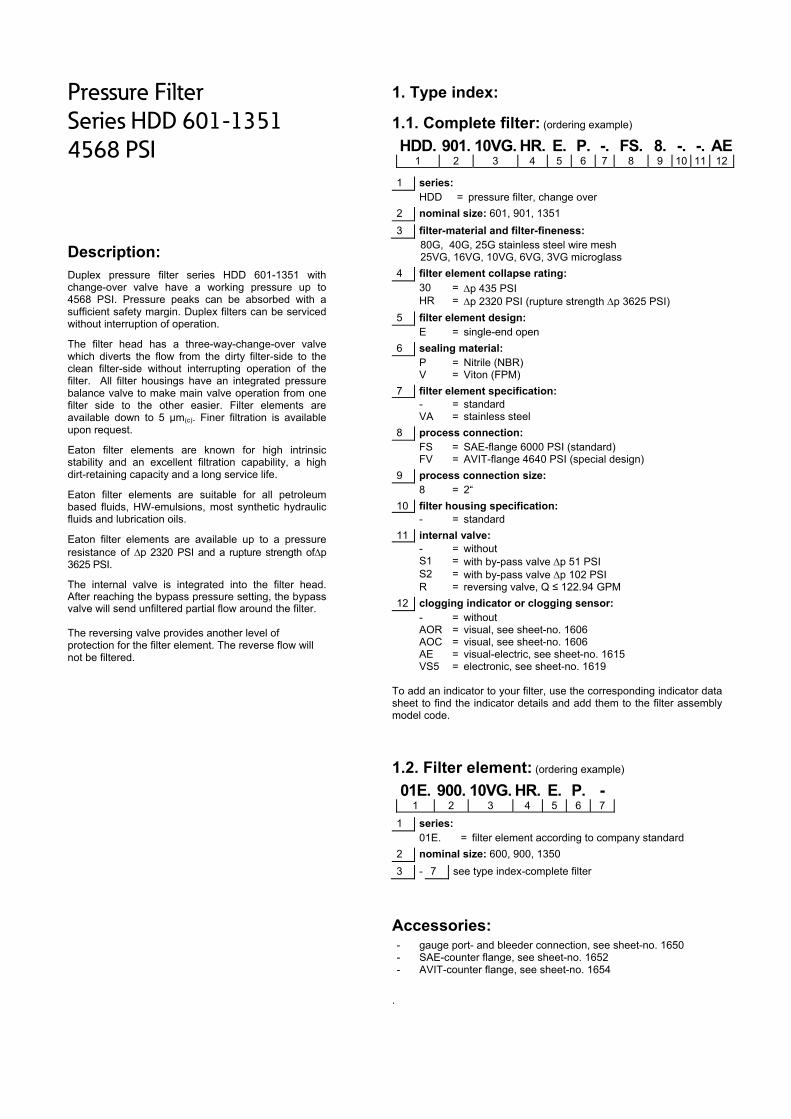
Pressure Filter
Series HDD 601-1351
4568 PSI
Description: Duplex pressure filter series HDD 601-1351 with change-over valve have a working pressure up to 4568 PSI. Pressure peaks can be absorbed with a sufficient safety margin. Duplex filters can be serviced without interruption of operation.
The filter head has a three-way-change-over valve which diverts the flow from the dirty filter-side to the clean filter-side without interrupting operation of the filter. All filter housings have an integrated pressure balance valve to make main valve operation from one filter side to the other easier. Filter elements are available down to 5 µm(c). Finer filtration is available upon request.
Eaton filter elements are known for high intrinsic stability and an excellent filtration capability, a high dirt-retaining capacity and a long service life.
Eaton filter elements are suitable for all petroleum based fluids, HW-emulsions, most synthetic hydraulic fluids and lubrication oils.
Eaton filter elements are available up to a pressure resistance of p 2320 PSI and a rupture strength ofp 3625 PSI.
The internal valve is integrated into the filter head. After reaching the bypass pressure setting, the bypass valve will send unfiltered partial flow around the filter. The reversing valve provides another level of protection for the filter element. The reverse flow will not be filtered.
1. Type index:
1.1. Complete filter: (ordering example)
HDD. 901. 10VG. HR. E. P. -. FS. 8. -. -. AE1 2 3 4 5 6 7 8 9 10 11 12
1 series: HDD = pressure filter, change over
2 nominal size: 601, 901, 1351
3 filter-material and filter-fineness: 80G, 40G, 25G stainless steel wire mesh 25VG, 16VG, 10VG, 6VG, 3VG microglass
4 filter element collapse rating: 30 = p 435 PSI HR = p 2320 PSI (rupture strength p 3625 PSI)
5 filter element design: E = single-end open
6 sealing material: P = Nitrile (NBR) V = Viton (FPM)
7 filter element specification: - = standard VA = stainless steel
8 process connection: FS = SAE-flange 6000 PSI (standard) FV = AVIT-flange 4640 PSI (special design)
9 process connection size: 8 = 2“
10 filter housing specification: - = standard
11 internal valve: - = without S1 = with by-pass valve p 51 PSI S2 = with by-pass valve p 102 PSI R = reversing valve, Q ≤ 122.94 GPM
12 clogging indicator or clogging sensor: - = without AOR = visual, see sheet-no. 1606 AOC = visual, see sheet-no. 1606 AE = visual-electric, see sheet-no. 1615 VS5 = electronic, see sheet-no. 1619
To add an indicator to your filter, use the corresponding indicator data sheet to find the indicator details and add them to the filter assembly model code.
1.2. Filter element: (ordering example)
01E. 900. 10VG. HR. E. P. - 1 2 3 4 5 6 7
1 series: 01E. = filter element according to company standard
2 nominal size: 600, 900, 1350
3 - 7 see type index-complete filter
Accessories:
- gauge port- and bleeder connection, see sheet-no. 1650 - SAE-counter flange, see sheet-no. 1652 - AVIT-counter flange, see sheet-no. 1654
.

Technical data:
design temperature: 14 °F to +212 °F operating temperature: 14 °F to +176 °F operating medium mineral oil, other media on request max. operating pressure: 4538 PSI test pressure: 6525 PSI process connection: SAE-flange 6000 PSI (standard) or AVIT-flange 4640 PSI (special design) housing material: EN-GJS-400-18-LT, C-steel sealing material: Nitrile (NBR) or Viton (FPM), other materials on request installation position: vertical air bleeding connections: BSPP ¼ measure connections: BSPP ¼
Classified under the Pressure Equipment Directive 2014/68/EC for mineral oil (fluid group 2), Article 4, Para. 3. Classified under ATEX Directive 2014/34/EC according to specific application (see questionnaire sheet-no. 34279-4).
Pressure drop flow curves:
Filter calculation/sizing
The pressure drop of the assembly at a given flow rate Q is the sum of the housing ∆p and the element ∆p and is calculated as follows:
p assembly = p housing + p element p housing = (see p = f (Q) - characteristics)
p element (PSI) = .
³
For ease of calculation our Filter Selection tool is available online at www.eatonpowersource.com/calculators/filtration/
Material gradient coefficients (MSK) for filter elements
The material gradient coefficients in PSI/GPM apply to mineral oil (HLP) with a density of 0.876 kg/dm³ and a kinematic viscosity of 139 SUS (30 mm²/s). The pressure drop changes proportionally to the change in kinematic viscosity and density.
HDD VG G
3VG 6VG 10VG 16VG 25VG 25G 40G 80G
601 0.963 0.669 0.428 0.368 0.251 0.0303 0.0282 0.0193
901 0.668 0.464 0.297 0.225 0.174 0.0189 0.0177 0.0121
1351 0.417 0.290 0.185 0.185 0.109 0.0122 0.0114 0.0078
∆p = f(Q) – characteristics according to ISO 3968
The pressure drop characteristics apply to mineral oil (HLP) with a density of 0.876 kg/dm³. The pressure drop changes proportionally to the density.

Symbols: without indicator with electric
indicator AE 30 and AE 40
with visual-electric indicator
AE 50 and AE 62
with visual-electric indicator
AE 70 and AE 80
with visual indicator
AOR/AOC
with electronic clogging sensor
VS5 filter without internal valve
filter with by-pass valve
filter with reversing valve
Spare parts:
item qty. designation dimension article-no. HDD 601 HDD 901 HDD 1351
1 2 filter element 01E.600… 01E.900… 01E.1350… 2 2 O-ring 48 x 3 304357 (NBR) 304404 (FPM) 3 2 O-ring 98 x 4 301914 (NBR) 304765 (FPM) 4 2 support ring 110 x 3,5 x 2 304802 5 2 O-ring 18 x 3 304359 (NBR) 304399 (FPM) 6 2 support ring 25 x 2,5 x 0,5 311311 7 2 O-ring 71 x 3 306451 (NBR) 306897 (FPM) 8 2 screw plug ½ BSPP 304678 9 1 clogging indicator, visual AOR or AOC see sheet no. 1606
10 1 clogging indicator, visual-electric AE see sheet no. 1615 11 1 clogging sensor, electronic VS5 see sheet no. 1619 12 1 O-ring 15 x 1,5 315457 (NBR) 315427 (FPM) 13 1 O-ring 22 x 2 304708 (NBR) 304721 (FPM) 14 1 O-ring 14 x 2 304342 (NBR) 304722 (FPM) 15 1 screw plug 20913-4 309817 16 4 screw plug ¼ BSPP 305003 17 1 pressure balance valve 3/8“ 305000 18 1 O-ring (only with counter flange SAE) 56,75 x 3,53 306035 (NBR) 310264 (FPM) 19 1 O-ring (only with counter flange AVIT) 61 x 5 20 8 screw plug 1½ BSPP 311475
item 15 execution only without clogging indicator or clogging sensor
Test methods: Filter elements are tested according to the following ISO standards:
ISO 2941 Verification of collapse/burst resistance ISO 2942 Verification of fabrication integrity ISO 2943 Verification of material compatibility with fluids ISO 3723 Method for end load test ISO 3724 Verification of flow fatigue characteristics ISO 3968 Evaluation of pressure drop versus flow characteristics ISO 16889 Multi-pass method for evaluating filtration performance
North America 44 Apple Street Tinton Falls, NJ 07724
Toll Free: 800 656-3344 (North America only)
Tel: +1 732 212-4700 Europe/Africa/Middle East Auf der Heide 2 53947 Nettersheim, Germany
Tel: +49 2486 809-0
Friedensstraße 41 68804 Altlußheim, Germany
Tel: +49 6205 2094-0
An den Nahewiesen 24 55450 Langenlonsheim, Germany
Tel: +49 6704 204-0
China No. 3, Lane 280, Linhong Road Changning District, 200335 Shanghai, P.R. China
Tel: +86 21 5200-0099 Singapore 4 Loyang Lane #04-01/02 Singapore 508914
Tel: +65 6825-1668 Brazil Av. Julia Gaioli, 474 – Bonsucesso 07251-500 – Guarulhos, Brazil
Tel: +55 11 2465-8822
For more information, please email us at [email protected]
or visit www.eaton.com/filtration
© 2015 Eaton. All rights reserved. All trademarks and registered trademarks are the property of their respective owners. All information and recommendations appearing in this brochure concerning the use of products described herein are based on tests believed to be reliable. However, it is the user’s responsibility to determine the suitability for his own use of such products. Since the actual use by others is beyond our control, no guarantee, expressed or implied, is made by Eaton as to the effects of such use or the results to be obtained. Eaton assumes no liability arising out of the use by others of such products. Nor is the information herein to be construed as absolutely complete, since additional information may be necessary or desirable when particular or exceptional conditions or circumstances exist or because of applicable laws or government regulations.
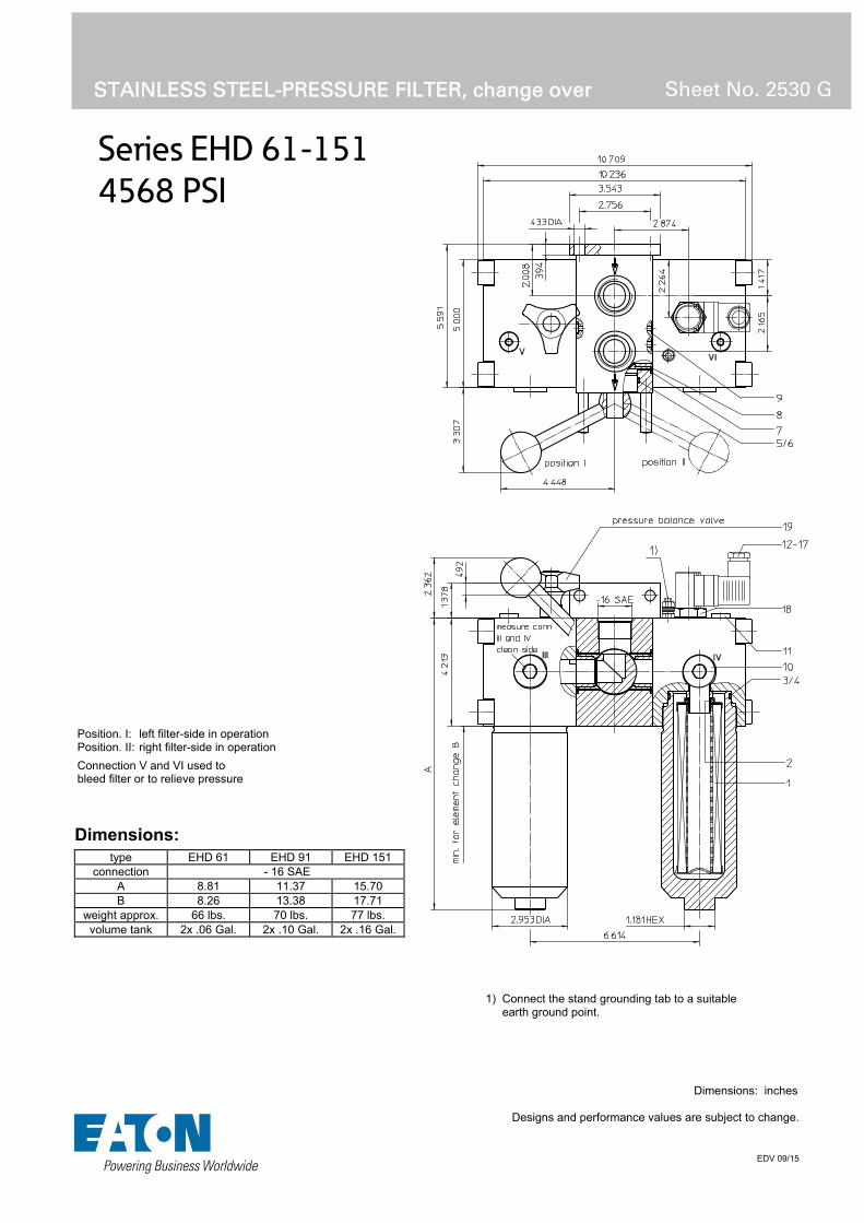
Series EHD 61-151
4568 PSI
STAINLESS STEEL-PRESSURE FILTER, change over Sheet No. 2530 G
EDV 09/15
1) Connect the stand grounding tab to a suitableearth ground point.
Dimensions: inches
Designs and performance values are subject to change.
Dimensions:
type EHD 61 EHD 91 EHD 151 connection - 16 SAE
A 8.81 11.37 15.70B 8.26 13.38 17.71
weight approx. 66 lbs. 70 lbs. 77 lbs. volume tank 2x .06 Gal. 2x .10 Gal. 2x .16 Gal.
Position. I: left filter-side in operation Position. II: right filter-side in operation
Connection V and VI used to bleed filter or to relieve pressure

Stainless Steel-Pressure Filter
Series EHD 61-151
4568 PSI
Description: Stainless steel duplex filters series EHD have a working pressure up to 4568 PSI. Duplex filters can be serviced without interruption of operation.
The filter head has a three-way-change-over valve which diverts the flow from the dirty filter-side to the clean filter-side without interrupting operation of the filter. All filter housings have an integrated pressure balance valve to make main valve operation from one filter side to the other easier. Filter elements are available down to 5 µm(c). Finer filtration is available upon request.
Eaton filter elements are known for high intrinsic stability and an excellent filtration capability, a high dirt-retaining capacity and a long service life.
Eaton filter elements are suitable for all petroleum based fluids, HW-emulsions, most synthetic hydraulic fluids and lubrication oils.
Eaton filter elements are available up to a pressure resistance of p 2320 PSI and a rupture strength ofp 3625 PSI.
The internal valve is integrated into the filter head. After reaching the bypass pressure setting, the bypass valve will send unfiltered partial flow around the filter. The reversing valve provides another level of protection for the filter element. The reverse flow will not be filtered.
1. Type index:
1.1. Complete filter: (ordering example)
EHD. 91. 10VG. HR. E. P. VA. UG. 5. VA. -. AE1 2 3 4 5 6 7 8 9 10 11 12
1 series: ÉHD = stainless steel-pressure filter, change over
2 nominal size: 61, 91, 151
3 filter-material and filter-fineness: 80G, 40G, 25G stainless steel wire mesh 25VG, 16VG, 10VG, 6VG, 3VG microglass
4 filter element collapse rating: 30 = p 435 PSI HR = p 2320 PSI (rupture strength p 3625 PSI)
5 filter element design: E = single-end open
6 sealing material: P = Nitrile (NBR) V = Viton (FPM)
7 filter element specification: (see catalog) - = standard VA = stainless steel
8 process connection: UG = thread connection
9 process connection size: 5 = -16 SAE
10 filter housing specification: VA = stainless steel
11 internal valve: - = without S1 = with by-pass valve p 51 PSI S2 = with by-pass valve p 102 PSI R = reversing valve, Q ≤ 18.50 GPM
12 clogging indicator or clogging sensor: - = without AOR = visual, see sheet-no. 1606 AOC = visual, see sheet-no. 1606 AE = visual-electric, see sheet-no. 1615 VS5 = electronic, see sheet-no. 1619
To add an indicator to your filter, use the corresponding indicator data sheet to find the indicator details and add them to the filter assembly model code.
1.2. Filter element: (ordering example)
01E. 90. 10VG. HR. E. P. VA 1 2 3 4 5 6 7
1 series: 01E. = filter element according to company standard
2 nominal size: 60, 90, 150
3 - 7 see type index-complete filter
Accessories:
- gauge port- and bleeder connection, see sheet-no. 1650
.

Technical data:
design temperature: 14 °F to +212 °F operating temperature: 14 °F to +176 °F operating medium mineral oil, other media on request max. operating pressure: 4568 PSI test pressure: 6532 PSI process connection: thread connection housing material: EN 10088-3-1.4571 (316 Ti according to AISI) sealing material: Nitrile (NBR) or Viton (FPM), other materials on request installation position: vertical air bleeding and measure connections dirt side: BSPP ¼ measure connections clean side: BSPP ¾
Classified under the Pressure Equipment Directive 2014/68/EC for mineral oil (fluid group 2), Article 4, Para. 3. Classified under ATEX Directive 2014/34/EC according to specific application (see questionnaire sheet-no. 34279-4).
Pressure drop flow curves:
Filter calculation/sizing
The pressure drop of the assembly at a given flow rate Q is the sum of the housing ∆p and the element ∆p and is calculated as follows:
p assembly = p housing + p element p housing = (see p = f (Q) - characteristics)
p element (PSI) = .
³
For ease of calculation our Filter Selection tool is available online at www.eatonpowersource.com/calculators/filtration/
Material gradient coefficients (MSK) for filter elements
The material gradient coefficients in PSI/GPM apply to mineral oil (HLP) with a density of 0.876 kg/dm³ and a kinematic viscosity of 139 SUS (30 mm²/s). The pressure drop changes proportionally to the change in kinematic viscosity and density.
EHD VG G
3VG 6VG 10VG 16VG 25VG 25G 40G 80G
61 6.748 4.685 2.999 2.577 1.760 0.2002 0.1868 0.1280
91 4.059 2.818 1.804 1.550 1.059 0.1210 0.1130 0.0774
151 2.422 1.681 1.076 0.925 0.632 0.0723 0.0675 0.0462
∆p = f(Q) – characteristics according to ISO 3968
The pressure drop characteristics apply to mineral oil (HLP) with a density of 0.876 kg/dm³. The pressure drop changes proportionally to the density.

Symbols:
without indicator with electric indicator
AE 30 and AE 40
with visual-electric indicator
AE 50 and AE 62
with visual-electric indicator
AE 70 and AE 80
with visual indicator
AOR/AOC
with electronic clogging sensor
VS5 filter without internal valve
filter with by-pass valve
filter with reversing valve
Spare parts:
item qty. designation dimension article-no. EHD 61 EHD 91 EHD 151
1 2 filter element 01E.60… 01E.90… 01E.150 … 2 2 O-ring 22 x 3,5 304341 (NBR) 304392 (FPM) 3 2 O-ring 56 x 3 305072 (NBR) 305322 (FPM) 4 2 support ring 63 x 2,6 x 1 312309 5 3 O-ring 45 x 3 304991 (NBR) 304997 (FPM) 6 2 support ring 49,7 x 2,4 x 1 317709 7 4 O-ring 38 x 3 304340 (NBR) 317013 (FPM) 8 4 O-ring 28 x 3 316778 (NBR) 318366 (FPM) 9 4 O-ring 8 x 2 310004 (NBR) 316530 (FPM)
10 2 screw plug ¾ BSPP 313815 11 2 screw plug ¼ BSPP 306968 12 1 clogging indicator, visual AOR or AOC see sheet-no. 1606 13 1 clogging indicator, visual-electric AE see sheet-no. 1615 14 1 clogging sensor, electronic VS5 see sheet-no. 1619 15 1 O-ring 15 x 1,5 315357 (NBR) 315427 (FPM) 16 1 O-ring 22 x 2 304708 (NBR) 304721 (FPM) 17 1 O-ring 14 x 2 304342 (NBR) 304722 (FPM) 18 1 screw plug 20913-4 314442 19 1 pressure balance valve 3/8“ 310316
item 18 execution only without clogging indicator or clogging sensor
Test methods: Filter elements are tested according to the following ISO standards:
ISO 2941 Verification of collapse/burst resistance ISO 2942 Verification of fabrication integrity ISO 2943 Verification of material compatibility with fluids ISO 3723 Method for end load test ISO 3724 Verification of flow fatigue characteristics ISO 3968 Evaluation of pressure drop versus flow characteristics ISO 16889 Multi-pass method for evaluating filtration performance
North America 44 Apple Street Tinton Falls, NJ 07724
Toll Free: 800 656-3344 (North America only)
Tel: +1 732 212-4700 Europe/Africa/Middle East Auf der Heide 2 53947 Nettersheim, Germany
Tel: +49 2486 809-0
Friedensstraße 41 68804 Altlußheim, Germany
Tel: +49 6205 2094-0
An den Nahewiesen 24 55450 Langenlonsheim, Germany
Tel: +49 6704 204-0
China No. 3, Lane 280, Linhong Road Changning District, 200335 Shanghai, P.R. China
Tel: +86 21 5200-0099 Singapore 4 Loyang Lane #04-01/02 Singapore 508914
Tel: +65 6825-1668 Brazil Av. Julia Gaioli, 474 – Bonsucesso 07251-500 – Guarulhos, Brazil
Tel: +55 11 2465-8822
For more information, please email us at [email protected]
or visit www.eaton.com/filtration
© 2015 Eaton. All rights reserved. All trademarks and registered trademarks are the property of their respective owners. All information and recommendations appearing in this brochure concerning the use of products described herein are based on tests believed to be reliable. However, it is the user’s responsibility to determine the suitability for his own use of such products. Since the actual use by others is beyond our control, no guarantee, expressed or implied, is made by Eaton as to the effects of such use or the results to be obtained. Eaton assumes no liability arising out of the use by others of such products. Nor is the information herein to be construed as absolutely complete, since additional information may be necessary or desirable when particular or exceptional conditions or circumstances exist or because of applicable laws or government regulations.

Series EHD 241-451
4568 PSI
STAINLESS STEEL-PRESSURE FILTER, change over
Sheet No. 2533 F
EDV 09/15
1) Connect the stand grounding tab to a suitable earth ground point.
Dimensions: inches Designs and performance values are subject to change.
Dimensions:
type EHD 241 EHD 451 connection SAE 1 ½“
A 15.67 22.95 B 13.88 30.67
weight approx. 224 lbs. 255 lbs. volume tank 2x .22 Gal. 2x .40 Gal.
Position. I: left filter-side in operation Position. II: right filter-side in operation
Connection III and IV used to bleed filter or to relieve pressure

Stainless Steel-Pressure Filter
Series EHD 241-451
4568 PSI
Description: Stainless steel duplex filters series EHD have a working pressure up to 4568 PSI. Duplex filters can be serviced without interruption of operation.
The filter head has a three-way-change-over valve which diverts the flow from the dirty filter-side to the clean filter-side without interrupting operation of the filter. All filter housings have an integrated pressure balance valve to make main valve operation from one filter side to the other easier. Filter elements are available down to 5 µm(c). Finer filtration is available upon request.
Eaton filter elements are known for high intrinsic stability and an excellent filtration capability, a high dirt-retaining capacity and a long service life.
Eaton filter elements are suitable for all petroleum based fluids, HW-emulsions, most synthetic hydraulic fluids and lubrication oils.
Eaton filter elements are available up to a pressure resistance of p 2320 PSI and a rupture strength ofp 3625 PSI.
The internal valve is integrated into the filter head. After reaching the bypass pressure setting, the bypass valve will send unfiltered partial flow around the filter. The reversing valve provides another level of protection for the filter element. The reverse flow will not be filtered.
1. Type index:
1.1. Complete filter: (ordering example)
EHD. 241. 10VG. HR. E. P. VA. FS. 7. VA. -. AE1 2 3 4 5 6 7 8 9 10 11 12
1 series: ÉHD = stainless steel-pressure filter, change over
2 nominal size: 241, 451
3 filter-material and filter-fineness: 80G, 40G, 25G stainless steel wire mesh 25VG, 16VG, 10VG, 6VG, 3VG microglass
4 filter element collapse rating: 30 = p 435 PSI HR = p 2320 PSI (rupture strength p 3625 PSI)
5 filter element design: E = single-end open
6 sealing material: P = Nitrile (NBR) V = Viton (FPM)
7 filter element specification: (see catalog) - = standard VA = stainless steel
8 process connection: FS = SAE-flange 3000 PSI
9 process connection size: 7 = 1 ½“
10 filter housing specification: VA = stainless steel
11 internal valve: - = without S1 = with by-pass valve p 51 PSI S2 = with by-pass valve p 102 PSI R = reversing valve, Q ≤ 55.75 GPM
12 clogging indicator or clogging sensor: - = without AOR = visual, see sheet-no. 1606 AOC = visual, see sheet-no. 1606 AE = visual-electric, see sheet-no. 1615 VS5 = electronic, see sheet-no. 1619
To add an indicator to your filter, use the corresponding indicator data sheet to find the indicator details and add them to the filter assembly model code.
1.2. Filter element: (ordering example)
01E. 240. 10VG. HR. E. P. VA 1 2 3 4 5 6 7
1 series: 01E. = filter element according to company standard
2 nominal size: 240, 450
3 - 7 see type index-complete filter
Accessories:
- gauge port- and bleeder connection, see sheet-no. 1650
.

Technical data:
design temperature: 14 °F to +212 °F operating temperature: 14 °F to +176 °F operating medium mineral oil, other media on request max. operating pressure: 4568 PSI test pressure: 6532 PSI process connection: SAE-flange 3000 PSI housing material: EN 10088-3-1.4571 (316 Ti according to AISI) sealing material: Nitrile (NBR) or Viton (FPM), other materials on request installation position: vertical air bleeding and measure connections: BSPP ¼
Classified under the Pressure Equipment Directive 2014/68/EC for mineral oil (fluid group 2), Article 4, Para. 3. Classified under ATEX Directive 2014/34/EC according to specific application (see questionnaire sheet-no. 34279-4).
Pressure drop flow curves:
Filter calculation/sizing
The pressure drop of the assembly at a given flow rate Q is the sum of the housing ∆p and the element ∆p and is calculated as follows:
p assembly = p housing + p element p housing = (see p = f (Q) - characteristics)
p element (PSI) = .
³
For ease of calculation our Filter Selection tool is available online at www.eatonpowersource.com/calculators/filtration/
Material gradient coefficients (MSK) for filter elements
The material gradient coefficients in PSI/GPM apply to mineral oil (HLP) with a density of 0.876 kg/dm³ and a kinematic viscosity of 139 SUS (30 mm²/s). The pressure drop changes proportionally to the change in kinematic viscosity and density.
EHD VG G
3VG 6VG 10VG 16VG 25VG 25G 40G 80G
241 2.092 1.452 0.930 0.799 0.546 0.0651 0.0607 0.0416
451 1.126 0.782 0.500 0.430 0.294 0.0349 0.0326 0.0223
∆p = f(Q) – characteristics according to ISO 3968
The pressure drop characteristics apply to mineral oil (HLP) with a density of 0.876 kg/dm³. The pressure drop changes proportionally to the density.

Symbols: without indicator with electric
indicator AE 30 and AE 40
with visual-electric indicator
AE 50 and AE 62
with visual-electric indicator
AE 70 and AE 80
with visual indicator
AOR/AOC
with electronic clogging sensor
VS5 filter without internal valve
filter with by-pass valve
filter with reversing valve
Spare parts:
item qty. designation dimension article-no. EHD 241 EHD 451
1 2 filter element 01E.240… 01E.450… 2 2 O-ring 34 x 3,5 304338 (NBR) 304730 (FPM) 3 2 O-ring 76 x 4 305599 (NBR) 310291 (FPM) 4 2 support ring 84 x 3,2 x 1,5 312307 5 3 O-ring 70 x 4 306253 (NBR) 310280 (FPM) 6 2 sliding ring 076 x70 x 45° 318070 7 4 O-ring 56 x 3 305072 (NBR) 305322 (FPM) 8 4 O-ring 42,52 x 2,62 304352 (NBR) 304393 (FPM) 9 4 O-ring 10 x 2 309998 (NBR) 310272 (FPM)
10 4 screw plug ¼ BSPP 306968 11 1 clogging indicator visual AOR or AOC see sheet-no. 1606 12 1 clogging indicator visual-electric AE see sheet-no. 1615 13 1 clogging sensor electronic VS5 see sheet-no. 1619 14 1 O-ring 15 x 1,5 315357 (NBR) 315427 (FPM) 15 1 O-ring 22 x 2 304708 (NBR) 304721 (FPM) 16 1 O-ring 14 x 2 304342 (NBR) 304722 (FPM) 17 1 screw plug 20913-4 314442 18 1 pressure balance valve 3/8“ 310316 19 4 screw plug 1 BSPP 308498
item 17 execution only without clogging indicator or clogging sensor
Test methods: Filter elements are tested according to the following ISO standards:
ISO 2941 Verification of collapse/burst resistance ISO 2942 Verification of fabrication integrity ISO 2943 Verification of material compatibility with fluids ISO 3723 Method for end load test ISO 3724 Verification of flow fatigue characteristics ISO 3968 Evaluation of pressure drop versus flow characteristics ISO 16889 Multi-pass method for evaluating filtration performance
North America 44 Apple Street Tinton Falls, NJ 07724
Toll Free: 800 656-3344 (North America only)
Tel: +1 732 212-4700 Europe/Africa/Middle East Auf der Heide 2 53947 Nettersheim, Germany
Tel: +49 2486 809-0
Friedensstraße 41 68804 Altlußheim, Germany
Tel: +49 6205 2094-0
An den Nahewiesen 24 55450 Langenlonsheim, Germany
Tel: +49 6704 204-0
China No. 3, Lane 280, Linhong Road Changning District, 200335 Shanghai, P.R. China
Tel: +86 21 5200-0099 Singapore 4 Loyang Lane #04-01/02 Singapore 508914
Tel: +65 6825-1668 Brazil Av. Julia Gaioli, 474 – Bonsucesso 07251-500 – Guarulhos, Brazil
Tel: +55 11 2465-8822
For more information, please email us at [email protected] or visit www.eaton.com/filtration
© 2015 Eaton. All rights reserved. All trademarks and registered trademarks are the property of their respective owners. All information and recommendations appearing in this brochure concerning the use of products described herein are based on tests believed to be reliable. However, it is the user’s responsibility to determine the suitability for his own use of such products. Since the actual use by others is beyond our control, no guarantee, expressed or implied, is made by Eaton as to the effects of such use or the results to be obtained. Eaton assumes no liability arising out of the use by others of such products. Nor is the information herein to be construed as absolutely complete, since additional information may be necessary or desirable when particular or exceptional conditions or circumstances exist or because of applicable laws or government regulations.

Series EHPF 60-150
4568 PSI
STAINLESS STEEL-PRESSURE FILTER
Sheet No. 1440 B
EDV 09/15
Dimensions: inches Designs and performance values are subject to change.
Dimensions:
type EHPF 60 EHPF 90 EHPF 150 connection ¾“
A 8.38 10.95 12.27 B 8.50 11.00 15.35
weight approx. 22 lbs. 24 lbs. 27 lbs. volume tank .08 Gal. .10 Gal. .16 Gal.

Stainless Steel-Pressure Filter
Series EHPF 60-150
4568 PSI
Description: Stainless steel pressure filter series EHPF 60-150 have a working pressure up to 4568 PSI. Pressure peaks can be absorbed with a sufficient safety margin. The EHPF-filters are flanged to the mounting-surface.
The filter element consists of star-shaped, pleated filter material, which is supported on the inside by a perforated core tube and is bonded to the end caps with a high-quality adhesive. The flow direction is from outside to inside. Filter elements are available down to 5 µm(c). Finer filtration is available upon request.
Eaton filter elements are known for high intrinsic stability and an excellent filtration capability, a high dirt-retaining capacity and a long service life.
Eaton filter elements are suitable for all petroleum based fluids, HW-emulsions, most synthetic hydraulic fluids and lubrication oils.
Eaton filter elements are available up to a pressure resistance of p 2320 PSI and a rupture strength ofp 3625 PSI.
The internal valve is integrated into the filter head. After reaching the bypass pressure setting, the bypass valve will send unfiltered partial flow around the filter.
The reversing valve provides another level of protection for the filter element. The reverse flow will not be filtered.
1. Type index:
1.1. Complete filter: (ordering example)
EHPF. 90. 10VG. HR. E. P. VA. F. 4. VA. -. AE1 2 3 4 5 6 7 8 9 10 11 12
1 series: EHPF = stainless steel-pressure filter, manifold mounted
2 nominal size: 60, 90, 150
3 filter-material and filter-fineness: 80G, 40G, 25G, 10G stainless steel wire mesh 25VG, 16VG, 10VG, 6VG, 3VG microglass
4 filter element collapse rating: 30 = p 435 PSI HR = p 2320 PSI (rupture strength p 3625 PSI)
5 filter element design: E = single-end open
6 sealing material: P = Nitrile (NBR) V = Viton (FPM)
7 filter element specification: (see catalog) - = standard VA = stainless steel IS06 = for HFC applications, see sheet-no. 31601
8 process connection: F = manifold mounted
9 process connection size: 4 = ¾“
10 filter housing specification: VA = standard
11 internal valve: - = without S1 = with bypass valve p 51 PSI S2 = with bypass valve p 102 PSI R = reversing valve, Q ≤ 18.50 GPM
12 clogging indicator or clogging sensor: - = without AOR = visual, see sheet-no. 1606 AOC = visual, see sheet-no. 1606 AE = visual-electric, see sheet-no. 1615 VS5 = electronic, see sheet-no. 1619
To add an indicator to your filter, use the corresponding indicator data sheet to find the indicator details and add them to the filter assembly model code.
1.2. Filter element: (ordering example)
01E. 90. 10VG. HR. E. P. VA 1 2 3 4 5 6 7
1 series: 01E. = filter element according to company standard
2 nominal size: 60, 90, 150
3 - 7 see type index-complete filter

Technical data:
design temperature: 14 °F to +212 °F operating temperature: 14 °F to +176 °F operating medium mineral oil, other media on request max. operating pressure: 4568 PSI test pressure: 6525 PSI process connection: manifold mounted housing material: EN10088-3 1.4571 (316 Ti according to AISI) sealing material: Nitrile (NBR) or Viton (FPM), other materials on request installation position: vertical
Classified under the Pressure Equipment Directive 2014/68/EC for mineral oil (fluid group 2), Article 4, Para. 3. Classified under ATEX Directive 2014/34/EC according to specific application (see questionnaire sheet-no. 34279-4)
Pressure drop flow curves:
Filter calculation/sizing
The pressure drop of the assembly at a given flow rate Q is the sum of the housing ∆p and the element ∆p and is calculated as follows:
p assembly = p housing + p element p housing = (see p = f (Q) - characteristics)
p element (PSI) = .
³
For ease of calculation our Filter Selection tool is available online at www.eatonpowersource.com/calculators/filtration/
Material gradient coefficients (MSK) for filter elements
The material gradient coefficients in PSI/GPM apply to mineral oil (HLP) with a density of 0.876 kg/dm³ and a kinematic viscosity of 139 SUS (30 mm²/s). The pressure drop changes proportionally to the change in kinematic viscosity and density.
EHPF VG G
3VG 6VG 10VG 16VG 25VG 25G 40G 80G
60 6.748 4.685 2.999 2.577 1.760 0.2002 0.1868 0.1280
90 4.059 2.818 1.804 1.550 1.059 0.1210 0.1130 0.0774
150 2.422 1.681 1.076 0.925 0.632 0.0723 0.0675 0.0462
∆p = f(Q) – characteristics according to ISO 3968
The pressure drop characteristics apply to mineral oil (HLP) with a density of 0.876 kg/dm³. The pressure drop changes proportionally to the density.

Symbols:
without indicator with electric indicator
AE 30 and AE 40
with visual-electric indicator
AE 50 and AE 62
with visual-electric indicator
AE 70 and AE 80
with visual indicator
AOR/AOC
with electronic clogging sensor
VS5
filter without internal valve
filter with by-pass valve
filter with reversing valve
Spare parts:
item qty. designation dimension article-no. EHPF 60 EHPF 90 EHPF 150
1 1 filer element 01E.60… 01E.90… 01E.150… 2 1 O-ring 22 x 3,5 304341 (NBR) 304392 (FPM) 3 1 O-ring 56 x 3 305072 (NBR) 305322 (FPM) 4 1 support ring 63 x 2,6 x 1 312309 5 2 O-ring 22 x 3 304387 (NBR) 304931 (FPM) 6 1 clogging indicator, visual AOR or AOC see sheet no. 1606 7 1 clogging indicator, visual-electric AE see sheet no. 1615 8 1 clogging sensor, electronic VS5 see sheet no. 1619 9 1 O-ring 15 x 1,5 315357 (NBR) 315427 (FPM)
10 1 O-ring 22 x 2 304708 (NBR) 304721 (FPM) 11 1 O-ring 14 x 2 304342 (NBR) 304722 (FPM) 12 1 screw plug 40171-4 314442
item 12 execution only without clogging indicator or clogging sensor
Test methods: Filter elements are tested according to the following ISO standards:
ISO 2941 Verification of collapse/burst resistance ISO 2942 Verification of fabrication integrity ISO 2943 Verification of material compatibility with fluids ISO 3723 Method for end load test ISO 3724 Verification of flow fatigue characteristics ISO 3968 Evaluation of pressure drop versus flow characteristics ISO 16889 Multi-pass method for evaluating filtration performance
North America 44 Apple Street Tinton Falls, NJ 07724
Toll Free: 800 656-3344 (North America only)
Tel: +1 732 212-4700 Europe/Africa/Middle East Auf der Heide 2 53947 Nettersheim, Germany
Tel: +49 2486 809-0
Friedensstraße 41 68804 Altlußheim, Germany
Tel: +49 6205 2094-0
An den Nahewiesen 24 55450 Langenlonsheim, Germany
Tel: +49 6704 204-0
China No. 3, Lane 280, Linhong Road Changning District, 200335 Shanghai, P.R. China
Tel: +86 21 5200-0099 Singapore 4 Loyang Lane #04-01/02 Singapore 508914
Tel: +65 6825-1668 Brazil Av. Julia Gaioli, 474 – Bonsucesso 07251-500 – Guarulhos, Brazil
Tel: +55 11 2465-8822
For more information, please email us at [email protected]
or visit www.eaton.com/filtration
© 2015 Eaton. All rights reserved. All trademarks and registered trademarks are the property of their respective owners. All information and recommendations appearing in this brochure concerning the use of products described herein are based on tests believed to be reliable. However, it is the user’s responsibility to determine the suitability for his own use of such products. Since the actual use by others is beyond our control, no guarantee, expressed or implied, is made by Eaton as to the effects of such use or the results to be obtained. Eaton assumes no liability arising out of the use by others of such products. Nor is the information herein to be construed as absolutely complete, since additional information may be necessary or desirable when particular or exceptional conditions or circumstances exist or because of applicable laws or government regulations.

Series EHPF 170-450
4568 PSI
STAINLESS STEEL-PRESSURE FILTER
Sheet No. 1441 B
EDV 09/15
Dimensions: inches Designs and performance values are subject to change.
Dimensions:
type EHPF 170 EHPF 240 EHPF 360 EHPF 450 connection 1“
A 13.11 15.07 18.22 22.36 B 13.00 14.00 18.00 22.00
weight approx. 48 lbs. 53 lbs. 57 lbs. 66 lbs. volume tank .18 Gal. .23 Gal. .31 Gal. .42 Gal.

Stainless Steel-Pressure Filter
Series EHPF 170-450
4568 PSI
Description: Stainless steel pressure filter series EHPF 170-450 have a working pressure up to 4568 PSI. Pressure peaks can be absorbed with a sufficient safety margin. The EHPF-filters are flanged to the mounting-surface.
The filter element consists of star-shaped, pleated filter material, which is supported on the inside by a perforated core tube and is bonded to the end caps with a high-quality adhesive. The flow direction is from outside to inside. Filter elements are available down to 5 µm(c). Finer filtration is available upon request.
Eaton filter elements are known for high intrinsic stability and an excellent filtration capability, a high dirt-retaining capacity and a long service life.
Eaton filter elements are suitable for all petroleum based fluids, HW-emulsions, most synthetic hydraulic fluids and lubrication oils.
Eaton filter elements are available up to a pressure resistance of p 2320 PSI and a rupture strength ofp 3625 PSI.
The internal valve is integrated into the filter head. After reaching the bypass pressure setting, the bypass valve will send unfiltered partial flow around the filter.
The reversing valve provides another level of protection for the filter element. The reverse flow will not be filtered.
1. Type index:
1.1. Complete filter: (ordering example)
EHPF. 360.10VG. HR. E. P. VA. F. 5. VA. -. AE1 2 3 4 5 6 7 8 9 10 11 12
1 series: EHPF = stainless steel-pressure filter, manifold mounted
2 nominal size: 170, 240, 360, 450
3 filter-material and filter-fineness: 80G, 40G, 25G, 10G stainless steel wire mesh 25VG, 16VG, 10VG, 6VG, 3VG microglass
4 filter element collapse rating: 30 = p 435 PSI HR = p 2320 PSI (rupture strength p 3625 PSI)
5 filter element design: E = single-end open
6 sealing material: P = Nitrile (NBR) V = Viton (FPM)
7 filter element specification: (see catalog) - = standard VA = stainless steel IS06 = for HFC applications, see sheet-no. 31601
8 process connection: F = manifold mounted
9 process connection size: 5 = 1“
10 filter housing specification: VA = standard
11 internal valve: - = without S1 = with bypass valve p 51 PSI S2 = with bypass valve p 102 PSI R = reversing valve, Q ≤ 55.75 GPM
12 clogging indicator or clogging sensor: - = without AOR = visual, see sheet-no. 1606 AOC = visual, see sheet-no. 1606 AE = visual-electric, see sheet-no. 1615 VS5 = electronic, see sheet-no. 1619
To add an indicator to your filter, use the corresponding indicator data sheet to find the indicator details and add them to the filter assembly model code.
1.2. Filter element: (ordering example)
01E. 360.10VG. HR. E. P. VA 1 2 3 4 5 6 7
1 series: 01E. = filter element according to company standard
2 nominal size: 170, 240, 360, 450
3 - 7 see type index-complete filter

Technical data:
design temperature: 14 °F to +212 °F operating temperature: 14 °F to +176 °F operating medium mineral oil, other media on request max. operating pressure: 4568 PSI test pressure: 6525 PSI process connection: manifold mounted housing material: EN10088-3 1.4571 (316 Ti according to AISI) sealing material: Nitrile (NBR) or Viton (FPM), other materials on request installation position: vertical
Classified under the Pressure Equipment Directive 2014/68/EC for mineral oil (fluid group 2), Article 4, Para. 3. Classified under ATEX Directive 2014/34/EC according to specific application (see questionnaire sheet-no. 34279-4)
Pressure drop flow curves:
Filter calculation/sizing
The pressure drop of the assembly at a given flow rate Q is the sum of the housing ∆p and the element ∆p and is calculated as follows:
p assembly = p housing + p element p housing = (see p = f (Q) - characteristics)
p element (PSI) = .
³
For ease of calculation our Filter Selection tool is available online at www.eatonpowersource.com/calculators/filtration/
Material gradient coefficients (MSK) for filter elements
The material gradient coefficients in PSI/GPM apply to mineral oil (HLP) with a density of 0.876 kg/dm³ and a kinematic viscosity of 139 SUS (30 mm²/s). The pressure drop changes proportionally to the change in kinematic viscosity and density.
EHPF VG G
3VG 6VG 10VG 16VG 25VG 25G 40G 80G
170 2.714 1.884 1.206 1.036 0.708 0.0839 0.0783 0.0537
240 2.092 1.452 0.930 0.799 0.546 0.0651 0.0607 0.0416
360 1.530 1.062 0.680 0.584 0.399 0.0475 0.0444 0.0304
450 1.126 0.782 0.500 0.430 0.294 0.0349 0.0326 0.0223
∆p = f(Q) – characteristics according to ISO 3968
The pressure drop characteristics apply to mineral oil (HLP) with a density of 0.876 kg/dm³. The pressure drop changes proportionally to the density.
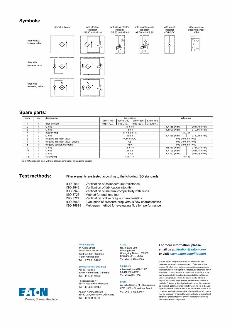
Symbols: without indicator with electric
indicator AE 30 and AE 40
with visual-electric indicator
AE 50 and AE 62
with visual-electric indicator
AE 70 and AE 80
with visual indicator
AOR/AOC
with electronic clogging sensor
VS5 filter without internal valve
filter with by-pass valve
filter with reversing valve
Spare parts:
item qty. designation dimensions article-no. EHPF 170 EHPF 240 EHPF 360 EHPF 450
1 1 filter element 01E.170… 01E.240… 01E.360… 01E.450… 2 1 O-ring 34 x 3,5 304338 (NBR) 304730 (FPM) 3 1 O-ring 76 x 4 305599 (NBR) 310291 (FPM) 4 1 support ring 84 x 3,2 x 1,5 312307 5 2 O-ring 32 x 3 304368 (NBR) 311020 (FPM) 6 1 clogging indicator, visual AOR or AOC see sheet-no. 1606 7 1 clogging indicator, visual-electric AE see sheet-no. 1615 8 1 clogging sensor, electronic VS5 see sheet-no. 1619 9 1 O-ring 15 x 1,5 315357 (NBR) 315427 (FPM)
10 1 O-ring 22 x 2 304708 (NBR) 304721 (FPM) 11 1 O-ring 14 x 2 304342 (NBR) 304722 (FPM) 12 1 screw plug 40171-4 314442
item 12 execution only without clogging indicator or clogging sensor
Test methods: Filter elements are tested according to the following ISO standards:
ISO 2941 Verification of collapse/burst resistance ISO 2942 Verification of fabrication integrity ISO 2943 Verification of material compatibility with fluids ISO 3723 Method for end load test ISO 3724 Verification of flow fatigue characteristics ISO 3968 Evaluation of pressure drop versus flow characteristics ISO 16889 Multi-pass method for evaluating filtration performance
North America 44 Apple Street Tinton Falls, NJ 07724
Toll Free: 800 656-3344 (North America only)
Tel: +1 732 212-4700 Europe/Africa/Middle East Auf der Heide 2 53947 Nettersheim, Germany
Tel: +49 2486 809-0
Friedensstraße 41 68804 Altlußheim, Germany
Tel: +49 6205 2094-0
An den Nahewiesen 24 55450 Langenlonsheim, Germany
Tel: +49 6704 204-0
China No. 3, Lane 280, Linhong Road Changning District, 200335 Shanghai, P.R. China
Tel: +86 21 5200-0099 Singapore 4 Loyang Lane #04-01/02 Singapore 508914
Tel: +65 6825-1668 Brazil Av. Julia Gaioli, 474 – Bonsucesso 07251-500 – Guarulhos, Brazil
Tel: +55 11 2465-8822
For more information, please email us at [email protected]
or visit www.eaton.com/filtration
© 2015 Eaton. All rights reserved. All trademarks and registered trademarks are the property of their respective owners. All information and recommendations appearing in this brochure concerning the use of products described herein are based on tests believed to be reliable. However, it is the user’s responsibility to determine the suitability for his own use of such products. Since the actual use by others is beyond our control, no guarantee, expressed or implied, is made by Eaton as to the effects of such use or the results to be obtained. Eaton assumes no liability arising out of the use by others of such products. Nor is the information herein to be construed as absolutely complete, since additional information may be necessary or desirable when particular or exceptional conditions or circumstances exist or because of applicable laws or government regulations.

Series EH 31
6000 PSI
STAINLESS STEEL-PRESSURE FILTER
Sheet No. 1435 G
EDV 10/15
1) Connect the stand grounding tab to a suitable earth ground point.
Weight: approx. 7 lbs.
Dimensions: inches Designs and performance values are subject to change.

Pressure Filter
Series EH 31
6000 PSI
Description: The stainless steel pressure filters series EH 31 have a working pressure up to 6000 PSI. The EH-filter is in-line mounted.
The filter element consists of star-shaped, pleated filter material, which is supported on the inside by a perforated core tube and is bonded to the end caps with a high-quality adhesive. The flow direction is from outside to inside. Filter elements are available down to 4 µm(c).
Eaton filter elements are known for high intrinsic stability and an excellent filtration capability, a high dirt-retaining capacity and a long service life.
Eaton filter elements can be used for petroleum-based fluids, HW emulsions, water glycols, most synthetic fluids and lubrication fluids. Consult factory for specific fluid applications.
Eaton filter elements are available up to a pressure resistance of p 2320 PSI and a rupture strength ofp 3625 PSI.
The internal valve is integrated into the filter head. After reaching the bypass pressure setting, the bypass valve will send unfiltered partial flow around the filter.
1. Type index:
1.1. Complete filter: (ordering example)
EH. 31. 10VG. HR. E. P. VA. UG. 3. VA. -. AE1 2 3 4 5 6 7 8 9 10 11 12
1 series: EH = stainless steel-pressure filter
2 nominal size: 31
3 filter-material and filter-fineness: 80G, 40G, 25G, 10G stainless steel wire mesh 25VG, 16VG, 10VG, 6VG, 3VG microglass
4 filter element collapse rating: 30 = p 435 PSI HR = p 2320 PSI (rupture strength p 3625 PSI)
5 filter element design: E = single-end open
6 sealing material: P = Nitrile (NBR) V = Viton (FPM)
7 filter element specification: (see catalog) - = standard VA = stainless steel IS06 = for HFC applications, see sheet-no. 31601
8 process connection: UG = thread connection NPT = thread connection according to ANSI B1.20.1
9 process connection size: 3 = -8 SAE or ½“ NPT
10 filter housing specification: VA = stainless steel
11 internal valve: - = without S1 = with by-pass valve p 51 PSI S2 = with by-pass valve p 102 PSI
12 clogging indicator or clogging sensor: - = without AOR = visual, see sheet-no. 1606 AOC = visual, see sheet-no. 1606 AE = visual-electric, see sheet-no. 1615 VS5 = electronic, see sheet-no. 1619
To add an indicator to your filter, use the corresponding indicator data sheet to find the indicator details and add them to the filter assembly model code.
1.2. Filter element: (ordering example)
01E. 30. 10VG. HR. E. P. VA 1 2 3 4 5 6 7
1 series: 01E. = filter element according to company standard
2 nominal size: 30
3 - 7 see type index-complete filter
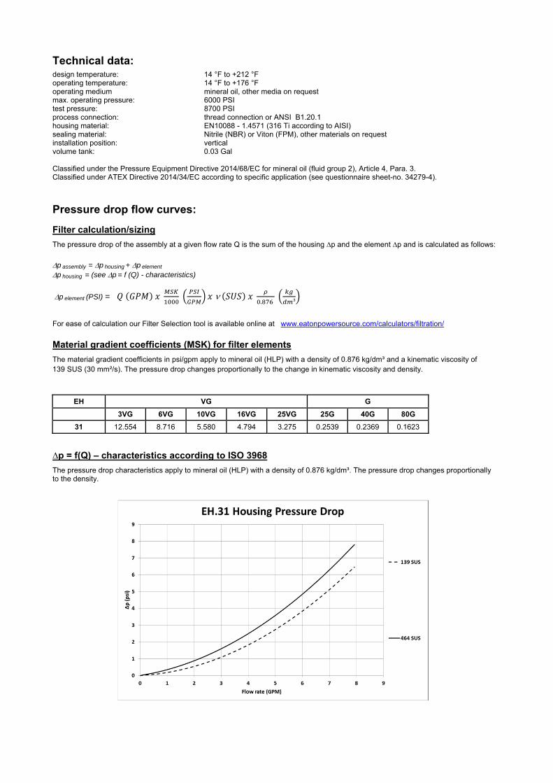
Technical data:
design temperature: 14 °F to +212 °F operating temperature: 14 °F to +176 °F operating medium mineral oil, other media on request max. operating pressure: 6000 PSI test pressure: 8700 PSI process connection: thread connection or ANSI B1.20.1 housing material: EN10088 - 1.4571 (316 Ti according to AISI) sealing material: Nitrile (NBR) or Viton (FPM), other materials on request installation position: vertical volume tank: 0.03 Gal
Classified under the Pressure Equipment Directive 2014/68/EC for mineral oil (fluid group 2), Article 4, Para. 3. Classified under ATEX Directive 2014/34/EC according to specific application (see questionnaire sheet-no. 34279-4).
Pressure drop flow curves: Filter calculation/sizing
The pressure drop of the assembly at a given flow rate Q is the sum of the housing ∆p and the element ∆p and is calculated as follows:
p assembly = p housing + p element p housing = (see p = f (Q) - characteristics)
p element (PSI) = .
³
For ease of calculation our Filter Selection tool is available online at www.eatonpowersource.com/calculators/filtration/
Material gradient coefficients (MSK) for filter elements
The material gradient coefficients in psi/gpm apply to mineral oil (HLP) with a density of 0.876 kg/dm³ and a kinematic viscosity of 139 SUS (30 mm²/s). The pressure drop changes proportionally to the change in kinematic viscosity and density.
EH VG G
3VG 6VG 10VG 16VG 25VG 25G 40G 80G
31 12.554 8.716 5.580 4.794 3.275 0.2539 0.2369 0.1623
∆p = f(Q) – characteristics according to ISO 3968
The pressure drop characteristics apply to mineral oil (HLP) with a density of 0.876 kg/dm³. The pressure drop changes proportionally to the density.

Symbols: without indicator with electric
indicator AE 30 and AE 40
with visual-electric indicator
AE 50 and AE 62
with visual-electric indicator
AE 70 and AE 80
with visual indicator
AOR/AOC
with electronic clogging sensor
VS5 filter without internal valve
filter with by-pass valve
Spare parts:
item qty. designation dimension article-no. 1 1 filter element 01E.90… 2 1 O-ring 11 x 3 312603 (NBR) 312727 (FPM) 3 1 O-ring 42 x 3,5 329381 (NBR) 338204 (FPM) 4 1 support ring 48 x 2,6 x 1 305391 5 1 clogging indicator, visual AOR or AOC see sheet-no. 1606 6 1 clogging indicator, visual-electric AE see sheet-no. 1615 7 1 clogging sensor, electronic VS5 see sheet-no. 1619 8 1 O-ring 15 x 1,5 315357 (NBR) 315427 (FPM) 9 1 O-ring 22 x 2 304708 (NBR) 304721 (FPM)
10 1 O-ring 14 x 2 304342 (NBR) 304722 (FPM) 11 1 screw plug 20913-4 314442
item 11 execution only without clogging indicator or clogging sensor
Test methods: Filter elements are tested according to the following ISO standards:
ISO 2941 Verification of collapse/burst resistance ISO 2942 Verification of fabrication integrity ISO 2943 Verification of material compatibility with fluids ISO 3723 Method for end load test ISO 3724 Verification of flow fatigue characteristics ISO 3968 Evaluation of pressure drop versus flow characteristics ISO 16889 Multi-pass method for evaluating filtration performance
North America 44 Apple Street Tinton Falls, NJ 07724
Toll Free: 800 656-3344 (North America only)
Tel: +1 732 212-4700 Europe/Africa/Middle East Auf der Heide 2 53947 Nettersheim, Germany
Tel: +49 2486 809-0
Friedensstraße 41 68804 Altlußheim, Germany
Tel: +49 6205 2094-0
An den Nahewiesen 24 55450 Langenlonsheim, Germany
Tel: +49 6704 204-0
China No. 3, Lane 280, Linhong Road Changning District, 200335 Shanghai, P.R. China
Tel: +86 21 5200-0099 Singapore 4 Loyang Lane #04-01/02 Singapore 508914
Tel: +65 6825-1668 Brazil Av. Julia Gaioli, 474 – Bonsucesso 07251-500 – Guarulhos, Brazil
Tel: +55 11 2465-8822
For more information, please email us at [email protected]
or visit www.eaton.com/filtration
© 2015 Eaton. All rights reserved. All trademarks and registered trademarks are the property of their respective owners. All information and recommendations appearing in this brochure concerning the use of products described herein are based on tests believed to be reliable. However, it is the user’s responsibility to determine the suitability for his own use of such products. Since the actual use by others is beyond our control, no guarantee, expressed or implied, is made by Eaton as to the effects of such use or the results to be obtained. Eaton assumes no liability arising out of the use by others of such products. Nor is the information herein to be construed as absolutely complete, since additional information may be necessary or desirable when particular or exceptional conditions or circumstances exist or because of applicable laws or government regulations.

Series EH 60-150
6000 PSI
STAINLESS STEEL-PRESSURE FILTER
Sheet No. 1430 N
EDV 10/15
1) Connect the stand grounding tab to a suitable earth ground point.
Dimensions: inches Designs and performance values are subject to change.
Dimensions:
type EH 60 EH 90 EH 150
connection - 8 SAE
or NPT ½“
-12 SAE or
NPT ¾“
-16 SAE or
NPT 1“ A 7.67 10.23 14.56 B 3.07 3.07 3.30 C 8.46 11.02 15.35 D .78 .78 .90 E 3.54 3.54 3.74 F 3.22 3.22 3.30
weight approx. 18.70 lbs. 20.95 lbs. 27.55 lbs. volume tank .08 Gal. .10 Gal. .16 Gal.
Connection assignments as shown in the table are standard. To exchange connections see item 9 in type index.

Pressure Filter
Series EH 60-150
6000 PSI
Description: The stainless steel pressure filters series EH 60-150 have a working pressure up to 6000 PSI. The EH-filter is in-line mounted.
The filter element consists of star-shaped, pleated filter material, which is supported on the inside by a perforated core tube and is bonded to the end caps with a high-quality adhesive. The flow direction is from outside to inside. Filter elements are available down to 4 µm(c).
Eaton filter elements are known for high intrinsic stability and an excellent filtration capability, a high dirt-retaining capacity and a long service life.
Eaton filter elements can be used for petroleum-based fluids, HW emulsions, water glycols, most synthetic fluids and lubrication fluids. Consult factory for specific fluid applications.
Eaton filter elements are available up to a pressure resistance of p 2320 PSI and a rupture strength ofp 3625 PSI.
The internal valve is integrated into the filter head. After reaching the bypass pressure setting, the bypass valve will send unfiltered partial flow around the filter.
The reversing valve provides another level of protection for the filter element. The reverse flow will not be filtered.
1. Type index:
1.1. Complete filter: (ordering example)
EH. 90. 10VG. HR. E. P. VA. UG. 4. VA. -. AE1 2 3 4 5 6 7 8 9 10 11 12
1 series: EH = stainless steel-pressure filter
2 nominal size: 60, 90, 150
3 filter-material and filter-fineness: 80G, 40G, 25G, 10G stainless steel wire mesh 25VG, 16VG, 10VG, 6VG, 3VG microglass
4 filter element collapse rating: 30 = p 435 PSI HR = p 2320 PSI (rupture strength p 3625 PSI)
5 filter element design: E = single-end open
6 sealing material: P = Nitrile (NBR) V = Viton (FPM)
7 filter element specification: (see catalog) - = standard VA = stainless steel IS06 = for HFC applications, see sheet-no. 31601
8 process connection: UG = thread connection NPT = thread connection according to ANSI B1.20.1
9 process connection size: 3 = -8 SAE or ½“ NPT 4 = -12 SAE or ¾“ NPT 5 = -16 SAE or 1 NPT
10 filter housing specification: (see catalog) VA = stainless steel
11 internal valve: - = without S1 = with by-pass valve p 51 PSI S2 = with by-pass valve p 102 PSI R = with reversing valve, Q ≤ 55.75 GPM
12 clogging indicator or clogging sensor: - = without AOR = visual, see sheet-no. 1606 AOC = visual, see sheet-no. 1606 AE = visual-electric, see sheet-no. 1615 VS5 = electronic, see sheet-no. 1619
To add an indicator to your filter, use the corresponding indicator data sheet to find the indicator details and add them to the filter assembly model code.
1.2. Filter element: (ordering example)
01E. 90. 10VG. HR. E. P. VA 1 2 3 4 5 6 7
1 series: 01E. = filter element according to company standard
2 nominal size: 60, 90, 150
3 - 7 see type index-complete filter
.

Technical data:
design temperature: 14 °F to +212 °F operating temperature: 14 °F to +176 °F operating medium mineral oil, other media on request max. operating pressure: 6000 PSI test pressure: 8700 PSI process connection: thread connection or ANSI B1.20.1 housing material: EN10088 - 1.4571 (316 Ti according to AISI) sealing material: Nitrile (NBR) or Viton (FPM), other materials on request installation position: vertical
Classified under the Pressure Equipment Directive 2014/68/EC for mineral oil (fluid group 2), Article 4, Para. 3. Classified under ATEX Directive 2014/34/EC according to specific application (see questionnaire sheet-no. 34279-4).
Pressure drop flow curves: Filter calculation/sizing
The pressure drop of the assembly at a given flow rate Q is the sum of the housing ∆p and the element ∆p and is calculated as follows:
p assembly = p housing + p element p housing = (see p = f (Q) - characteristics)
p element (PSI) = .
³
For ease of calculation our Filter Selection tool is available online at www.eatonpowersource.com/calculators/filtration/
Material gradient coefficients (MSK) for filter elements
The material gradient coefficients in psi/gpm apply to mineral oil (HLP) with a density of 0.876 kg/dm³ and a kinematic viscosity of 139 SUS (30 mm²/s). The pressure drop changes proportionally to the change in kinematic viscosity and density.
EH VG G
3VG 6VG 10VG 16VG 25VG 25G 40G 80G
60 6.748 4.685 2.999 2.577 1.760 0.2002 0.1868 0.1280
90 4.059 2.818 1.804 1.550 1.059 0.1210 0.1130 0.0774
150 2.422 1.681 1.076 0.925 0.632 0.0723 0.0675 0.0462
∆p = f(Q) – characteristics according to ISO 3968
The pressure drop characteristics apply to mineral oil (HLP) with a density of 0.876 kg/dm³. The pressure drop changes proportionally to the density.

Symbols: without indicator with electric
indicator AE 30 and AE 40
with visual-electric indicator
AE 50 and AE 62
with visual-electric indicator
AE 70 and AE 80
with visual indicator
AOR/AOC
with electronic clogging sensor
VS5 filter without internal valve
filter with by-pass valve
filter with reversing valve
Spare parts:
item qty. designation dimension article-no. EH 60 EH 90 EH 150
1 1 filer element 01E.60… 01E.90… 01E.150… 2 1 O-ring 22 x 3,5 304341 (NBR) 304392 (FPM) 3 1 O-ring 56 x 3 305072 (NBR) 305322 (FPM) 4 1 support ring 63 x 2,6 x 1 312309 5 1 clogging indicator, visual AOR or AOC see sheet no. 1606 6 1 clogging indicator, visual-electric AE see sheet no. 1615 7 1 clogging sensor, electronic VS5 see sheet no. 1619 8 1 O-ring 15 x 1,5 315357 (NBR) 315427 (FPM) 9 1 O-ring 22 x 2 304708 (NBR) 304721 (FPM)
10 1 O-ring 14 x 2 304342 (NBR) 304722 (FPM) 11 1 screw plug 20913-4 314442
item 11 execution only without clogging indicator or clogging sensor
Test methods: Filter elements are tested according to the following ISO standards:
ISO 2941 Verification of collapse/burst resistance ISO 2942 Verification of fabrication integrity ISO 2943 Verification of material compatibility with fluids ISO 3723 Method for end load test ISO 3724 Verification of flow fatigue characteristics ISO 3968 Evaluation of pressure drop versus flow characteristics ISO 16889 Multi-pass method for evaluating filtration performance
North America 44 Apple Street Tinton Falls, NJ 07724
Toll Free: 800 656-3344 (North America only)
Tel: +1 732 212-4700 Europe/Africa/Middle East Auf der Heide 2 53947 Nettersheim, Germany
Tel: +49 2486 809-0
Friedensstraße 41 68804 Altlußheim, Germany
Tel: +49 6205 2094-0
An den Nahewiesen 24 55450 Langenlonsheim, Germany
Tel: +49 6704 204-0
China No. 3, Lane 280, Linhong Road Changning District, 200335 Shanghai, P.R. China
Tel: +86 21 5200-0099 Singapore 4 Loyang Lane #04-01/02 Singapore 508914
Tel: +65 6825-1668 Brazil Av. Julia Gaioli, 474 – Bonsucesso 07251-500 – Guarulhos, Brazil
Tel: +55 11 2465-8822
For more information, please email us at [email protected]
or visit www.eaton.com/filtration
© 2015 Eaton. All rights reserved. All trademarks and registered trademarks are the property of their respective owners. All information and recommendations appearing in this brochure concerning the use of products described herein are based on tests believed to be reliable. However, it is the user’s responsibility to determine the suitability for his own use of such products. Since the actual use by others is beyond our control, no guarantee, expressed or implied, is made by Eaton as to the effects of such use or the results to be obtained. Eaton assumes no liability arising out of the use by others of such products. Nor is the information herein to be construed as absolutely complete, since additional information may be necessary or desirable when particular or exceptional conditions or circumstances exist or because of applicable laws or government regulations.

Series EH 240-450
6000 PSI
STAINLESS STEEL-PRESSURE FILTER
Sheet No. 1431 J
EDV 10/15
1) Connect the stand grounding tab to a suitable earth ground point.
Dimensions: inches Designs and performance values are subject to change.
Dimensions:
type EH 240 EH 450
connection -24 SAE
or SAE 1 ½“
A 14.96 22.24 B 12.90 20.27 C 12.59 19.68
weight approx. 48 lbs. 66 lbs. volume tank .22 Gal. .40 Gal.

Pressure Filter
Series EH 240-450
6000 PSI
Description: The stainless steel pressure filters series EH 240-450 have a working pressure up to 6000 PSI. The EH-filter is in-line mounted.
The filter element consists of star-shaped, pleated filter material, which is supported on the inside by a perforated core tube and is bonded to the end caps with a high-quality adhesive. The flow direction is from outside to inside. Filter elements are available down to 4 µm(c).
Eaton filter elements are known for high intrinsic stability and an excellent filtration capability, a high dirt-retaining capacity and a long service life.
Eaton filter elements can be used for petroleum-based fluids, HW emulsions, water glycols, most synthetic fluids and lubrication fluids. Consult factory for specific fluid applications.
Eaton filter elements are available up to a pressure resistance of p 2320 PSI and a rupture strength ofp 3625 PSI.
The internal valve is integrated into the filter head. After reaching the bypass pressure setting, the bypass valve will send unfiltered partial flow around the filter.
The reversing valve provides another level of protection for the filter element. The reverse flow will not be filtered.
1. Type index:
1.1. Complete filter: (ordering example)
EH. 240.10VG. HR. E. P. VA. FS. 7. VA. -. AE1 2 3 4 5 6 7 8 9 10 11 12
1 series: EH = stainless steel-pressure filter
2 nominal size: 240, 450
3 filter-material and filter-fineness: 80G, 40G, 25G, 10G stainless steel wire mesh 25VG, 16VG, 10VG, 6VG, 3VG microglass
4 filter element collapse rating: 30 = p 435 PSI HR = p 2320 PSI (rupture strength p 3625 PSI)
5 filter element design: E = single-end open
6 sealing material: P = Nitrile (NBR) V = Viton (FPM)
7 filter element specification: (see catalog) - = standard VA = stainless steel IS06 = for HFC applications, see sheet-no. 31601
8 process connection: UG = thread connection FS = SAE-flange 6000 PSI
9 process connection size: 7 = 1 ½“
10 filter housing specification: VA = stainless steel
11 internal valve: - = without S1 = with by-pass valve p 51 PSI S2 = with by-pass valve p 102 PSI R = with reversing valve, Q ≤ 55.75 GPM
12 clogging indicator or clogging sensor: - = without AOR = visual, see sheet-no. 1606 AOC = visual, see sheet-no. 1606 AE = visual-electric, see sheet-no. 1615 VS5 = electronic, see sheet-no. 1619
To add an indicator to your filter, use the corresponding indicator data sheet to find the indicator details and add them to the filter assembly model code.
1.2. Filter element: (ordering example)
01E. 240.10VG. HR. E. P. VA 1 2 3 4 5 6 7
1 series: 01E. = filter element according to company standard
2 nominal size: 240, 450
3 - 7 see type index-complete filter
.

Technical data:
design temperature: 14 °F to +212 °F operating temperature: 14 °F to +176 °F operating medium mineral oil, other media on request max. operating pressure: 6000 PSI test pressure: 8700 PSI process connection: thread connection or SAE-flange 6000 PSI housing material: EN10088 - 1.4571 (316 Ti according to AISI) sealing material: Nitrile (NBR) or Viton (FPM), other materials on request installation position: vertical
Classified under the Pressure Equipment Directive 2014/68/EC for mineral oil (fluid group 2), Article 4, Para. 3. Classified under ATEX Directive 2014/34/EC according to specific application (see questionnaire sheet-no. 34279-4).
Pressure drop flow curves: Filter calculation/sizing
The pressure drop of the assembly at a given flow rate Q is the sum of the housing ∆p and the element ∆p and is calculated as follows:
p assembly = p housing + p element p housing = (see p = f (Q) - characteristics)
p element (PSI) = .
³
For ease of calculation our Filter Selection tool is available online at www.eatonpowersource.com/calculators/filtration/
Material gradient coefficients (MSK) for filter elements
The material gradient coefficients in psi/gpm apply to mineral oil (HLP) with a density of 0.876 kg/dm³ and a kinematic viscosity of 139 SUS (30 mm²/s). The pressure drop changes proportionally to the change in kinematic viscosity and density.
EH VG G
3VG 6VG 10VG 16VG 25VG 25G 40G 80G
240 2.092 1.452 0.930 0.799 0.546 0.0651 0.0607 0.0416
450 1.126 0.782 0.500 0.430 0.294 0.0349 0.0326 0.0223
∆p = f(Q) – characteristics according to ISO 3968
The pressure drop characteristics apply to mineral oil (HLP) with a density of 0.876 kg/dm³. The pressure drop changes proportionally to the density.

Symbols: without indicator with electric
indicator AE 30 and AE 40
with visual-electric indicator
AE 50 and AE 62
with visual-electric indicator
AE 70 and AE 80
with visual indicator
AOR/AOC
with electronic clogging sensor
VS5 filter without internal valve
filter with by-pass valve
filter with reversing valve
Spare parts:
item qty. designation dimension article-no. EH 240 EH 450
1 1 filter element 01E.240… 01E.450… 2 1 O-ring 34 x 3,5 304338 (NBR) 304730 (FPM) 3 1 O-ring 76 x 4 305599 (NBR) 310291 (FPM) 4 1 support ring 84 x 3,2 x 1,5 312307 5 2 O-ring (only with counter flange) 47,22 x 3,53 305078 (NBR) 310269 (FPM) 6 2 counter flange 6000 PSI SAE 1 ½“ 322274 7 1 clogging indicator, visual AOR or AOC see sheet no. 1606 8 1 clogging indicator, visual-electric AE see sheet no. 1615 9 1 clogging sensor, electronic VS5 see sheet no. 1619
10 1 O-ring 15 x 1,5 315357 (NBR) 315427 (FPM) 11 1 O-ring 22 x 2 304708 (NBR) 304721 (FPM) 12 1 O-ring 14 x 2 304342 (NBR) 304722 (FPM) 13 1 screw plug 20913-4 314442
item 13 execution only without clogging indicator or clogging sensor
Test methods: Filter elements are tested according to the following ISO standards:
ISO 2941 Verification of collapse/burst resistance ISO 2942 Verification of fabrication integrity ISO 2943 Verification of material compatibility with fluids ISO 3723 Method for end load test ISO 3724 Verification of flow fatigue characteristics ISO 3968 Evaluation of pressure drop versus flow characteristics ISO 16889 Multi-pass method for evaluating filtration performance
North America 44 Apple Street Tinton Falls, NJ 07724
Toll Free: 800 656-3344 (North America only)
Tel: +1 732 212-4700 Europe/Africa/Middle East Auf der Heide 2 53947 Nettersheim, Germany
Tel: +49 2486 809-0
Friedensstraße 41 68804 Altlußheim, Germany
Tel: +49 6205 2094-0
An den Nahewiesen 24 55450 Langenlonsheim, Germany
Tel: +49 6704 204-0
China No. 3, Lane 280, Linhong Road Changning District, 200335 Shanghai, P.R. China
Tel: +86 21 5200-0099 Singapore 4 Loyang Lane #04-01/02 Singapore 508914
Tel: +65 6825-1668 Brazil Av. Julia Gaioli, 474 – Bonsucesso 07251-500 – Guarulhos, Brazil
Tel: +55 11 2465-8822
For more information, please email us at [email protected]
or visit www.eaton.com/filtration
© 2015 Eaton. All rights reserved. All trademarks and registered trademarks are the property of their respective owners. All information and recommendations appearing in this brochure concerning the use of products described herein are based on tests believed to be reliable. However, it is the user’s responsibility to determine the suitability for his own use of such products. Since the actual use by others is beyond our control, no guarantee, expressed or implied, is made by Eaton as to the effects of such use or the results to be obtained. Eaton assumes no liability arising out of the use by others of such products. Nor is the information herein to be construed as absolutely complete, since additional information may be necessary or desirable when particular or exceptional conditions or circumstances exist or because of applicable laws or government regulations.

Series EH 601-1351
4568 PSI
STAINLESS STEEL-PRESSURE FILTER
Sheet No. 1434 J
EDV 10/15
1) Connect the stand grounding tab to a suitable earth ground point.
Dimensions: inches Designs and performance values are subject to change.
Dimensions:
type EH 601 EH 901 EH 1351 connection SAE 2“
A 20.47 23.37 36.14 B 12.20 18.11 27.95
weight approx. 108 lbs. 123 lbs. 150 lbs. volume tank .55 Gal. .82 Gal. 1.21 Gal.

Pressure Filter
Series EH 601-1351
4568 PSI
Description: The stainless steel pressure filters series EH 601-1351have a working pressure up to 4568 PSI. . The EH-filter is in-line mounted.
The filter element consists of star-shaped, pleated filter material, which is supported on the inside by a perforated core tube and is bonded to the end caps with a high-quality adhesive. The flow direction is from outside to inside. Filter elements are available down to 4 µm(c).
Eaton filter elements are known for high intrinsic stability and an excellent filtration capability, a high dirt-retaining capacity and a long service life.
Eaton filter elements can be used for petroleum-based fluids, HW emulsions, water glycols, most synthetic fluids and lubrication fluids. Consult factory for specific fluid applications.
Eaton filter elements are available up to a pressure resistance of p 2320 PSI and a rupture strength ofp 3625 PSI.
The internal valve is integrated into the filter head. After reaching the bypass pressure setting, the bypass valve will send unfiltered partial flow around the filter.
The reversing valve provides another level of protection for the filter element. The reverse flow will not be filtered.
1. Type index:
1.1. Complete filter: (ordering example)
EH. 901.10VG. HR. E. P. VA. FS. 8. VA. -. AE1 2 3 4 5 6 7 8 9 10 11 12
1 series: EH = stainless steel-pressure filter
2 nominal size: 601, 901, 1351
3 filter-material and filter-fineness: 80G, 40G, 25G, 10G stainless steel wire mesh 25VG, 16VG, 10VG, 6VG, 3VG microglass
4 filter element collapse rating: 30 = p 435 PSI HR = p 2320 PSI (rupture strength p 3625 PSI)
5 filter element design: E = single-end open
6 sealing material: P = Nitrile (NBR) V = Viton (FPM)
7 filter element specification: (see catalog) - = standard VA = stainless steel IS06 = for HFC applications, see sheet-no. 31601
8 process connection: FS = SAE-flange 6000 PSI
9 process connection size: 8 = 2“
10 filter housing specification: VA = stainless steel
11 internal valve: - = without S1 = with by-pass valve p 51 PSI S2 = with by-pass valve p 102 PSI R = with reversing valve, Q ≤ 122.94 GPM
12 clogging indicator or clogging sensor: - = without AOR = visual, see sheet-no. 1606 AOC = visual, see sheet-no. 1606 AE = visual-electric, see sheet-no. 1615 VS5 = electronic, see sheet-no. 1619
To add an indicator to your filter, use the corresponding indicator data sheet to find the indicator details and add them to the filter assembly model code.
1.2. Filter element: (ordering example)
01E. 900.10VG. HR. E. P. VA 1 2 3 4 5 6 7
1 series: 01E. = filter element according to company standard
2 nominal size: 600, 900, 1350
3 - 7 see type index-complete filter
.

Technical data:
design temperature: 14 °F to +212 °F operating temperature: 14 °F to +176 °F operating medium mineral oil, other media on request max. operating pressure: 4568 PSI test pressure: 6525 PSI process connection: SAE-flange 6000 PSI housing material: EN10088 - 1.4571 (316 Ti according to AISI) sealing material: Nitrile (NBR) or Viton (FPM), other materials on request installation position: vertical
Classified under the Pressure Equipment Directive 2014/68/EC for mineral oil (fluid group 2), Article 4, Para. 3. Classified under ATEX Directive 2014/34/EC according to specific application (see questionnaire sheet-no. 34279-4).
Pressure drop flow curves: Filter calculation/sizing
The pressure drop of the assembly at a given flow rate Q is the sum of the housing ∆p and the element ∆p and is calculated as follows:
p assembly = p housing + p element p housing = (see p = f (Q) - characteristics)
p element (PSI) = .
³
For ease of calculation our Filter Selection tool is available online at www.eatonpowersource.com/calculators/filtration/
Material gradient coefficients (MSK) for filter elements
The material gradient coefficients in psi/gpm apply to mineral oil (HLP) with a density of 0.876 kg/dm³ and a kinematic viscosity of 139 SUS (30 mm²/s). The pressure drop changes proportionally to the change in kinematic viscosity and density.
EH VG G
3VG 6VG 10VG 16VG 25VG 25G 40G 80G
601 0.963 0.669 0.428 0.368 0.251 0.0303 0.0282 0.0193
901 0.668 0.464 0.297 0.225 0.174 0.0189 0.0177 0.0121
1351 0.417 0.290 0.185 0.185 0.109 0.0122 0.0114 0.0078
∆p = f(Q) – characteristics according to ISO 3968
The pressure drop characteristics apply to mineral oil (HLP) with a density of 0.876 kg/dm³. The pressure drop changes proportionally to the density.

Symbols:
without indicator with electric indicator
AE 30 and AE 40
with visual-electric indicator
AE 50 and AE 62
with visual-electric indicator
AE 70 and AE 80
with visual indicator
AOR/AOC
with electronic clogging sensor
VS5 filter without internal valve
filter with by-pass valve
filter with reversing valve
Spare parts:
item qty. designation dimension article-no. EH 601 EH 901 EH 1351
1 1 filer element 01E.600… 01E.900… 01E.1350… 2 1 O-ring 48 x 3 304357 (NBR) 304404 (FPM) 3 1 O-ring 98 x 4 301914 (NBR) 304765 (FPM) 4 1 support ring 110 x 3,5 x 2 304802 5 1 clogging indicator, visual AOR or AOC see sheet no. 1606 6 1 clogging indicator, visual-electrical AE see sheet no. 1615 7 1 clogging sensor, electronical VS1 see sheet no. 1617 8 1 O-ring 15 x 1,5 315357 (NBR) 315427 (FPM) 9 1 O-ring 22 x 2 304708 (NBR) 304721 (FPM)
10 1 O-ring 14 x 2 304342 (NBR) 304722 (FPM) 11 1 screw plug 20913-4 314442 12 1 screw plug ½ BSPP 306966
item 11 execution only without clogging indicator or clogging sensor
Test methods: Filter elements are tested according to the following ISO standards:
ISO 2941 Verification of collapse/burst resistance ISO 2942 Verification of fabrication integrity ISO 2943 Verification of material compatibility with fluids ISO 3723 Method for end load test ISO 3724 Verification of flow fatigue characteristics ISO 3968 Evaluation of pressure drop versus flow characteristics ISO 16889 Multi-pass method for evaluating filtration performance
North America 44 Apple Street Tinton Falls, NJ 07724
Toll Free: 800 656-3344 (North America only)
Tel: +1 732 212-4700 Europe/Africa/Middle East Auf der Heide 2 53947 Nettersheim, Germany
Tel: +49 2486 809-0
Friedensstraße 41 68804 Altlußheim, Germany
Tel: +49 6205 2094-0
An den Nahewiesen 24 55450 Langenlonsheim, Germany
Tel: +49 6704 204-0
China No. 3, Lane 280, Linhong Road Changning District, 200335 Shanghai, P.R. China
Tel: +86 21 5200-0099 Singapore 4 Loyang Lane #04-01/02 Singapore 508914
Tel: +65 6825-1668 Brazil Av. Julia Gaioli, 474 – Bonsucesso 07251-500 – Guarulhos, Brazil
Tel: +55 11 2465-8822
For more information, please email us at [email protected]
or visit www.eaton.com/filtration
© 2015 Eaton. All rights reserved. All trademarks and registered trademarks are the property of their respective owners. All information and recommendations appearing in this brochure concerning the use of products described herein are based on tests believed to be reliable. However, it is the user’s responsibility to determine the suitability for his own use of such products. Since the actual use by others is beyond our control, no guarantee, expressed or implied, is made by Eaton as to the effects of such use or the results to be obtained. Eaton assumes no liability arising out of the use by others of such products. Nor is the information herein to be construed as absolutely complete, since additional information may be necessary or desirable when particular or exceptional conditions or circumstances exist or because of applicable laws or government regulations.

Series EHP 31
11600/20300 PSI
STAINLESS STEEL-PRESSURE FILTER
Sheet No. 1438 C
EDV 09/15
Weight: approx. 6.5 lbs
Dimensions: inches Designs and performance values are subject to change.
1) Connect the stand grounding tab to a suitable earth ground point.

Stainless Steel-Pressure Filter
Series EHP 31
11600/20300 PSI
Description: Stainless steel pressure filter series EHP 31 have a working pressure up to 11600 or 20300 PSI. Pressure peaks can be absorbed with a sufficient safety margin. The HP-filter is in-line mounted.
The filter element consists of star-shaped, pleated filter material, which is supported on the inside by a perforated core tube and is bonded to the end caps with a high-quality adhesive. The flow direction is from outside to inside. Filter elements are available down to 4 µm(c).
Eaton filter elements are known for high intrinsic stability and an excellent filtration capability, a high dirt-retaining capacity and a long service life.
Eaton filter elements are suitable for all petroleum based fluids, HW-emulsions, most synthetic hydraulic fluids and lubrication oils.
Eaton filter elements are available up to a pressure resistance of p 2320 PSI and a rupture strength ofp 3625 PSI.
The bypass valve is integrated into the filter head. After reaching the bypass pressure setting, the bypass valve will send unfiltered partial flow around the filter.
1. Type index:
1.1. Complete filter: (ordering example)
EHP. 31. 10VG. HR. E. P. VA. NPT. 3. -. VA. -. 8001 2 3 4 5 6 7 8 9 10 11 12 13
1 series: EHP = stainless steel-pressure filter
2 nominal size: 31
3 filter-material and filter-fineness: 80G, 40G, 25G, 10G stainless steel wire mesh 25VG, 16VG, 10VG, 6VG, 3VG microglass
4 filter element collapse rating: 30 = p 435 PSI HR = p 2320 PSI (rupture strength p 3625 PSI)
5 filter element design: E = single-end open
6 sealing material: P = Nitrile (NBR) V = Viton (FPM)
7 filter element specification: (see catalog) - = standard VA = stainless steel IS06 = for HFC application, see sheet-no. 31601
8 process connection: UG2 = autoclave medium pressure NPT = thread connection
9 process connection size: 2 = MP 3/8“ (9/16“-18UNF) 3 = NPT ½
10 internal valve: - = without S1 = with by-pass valve p 51 PSI S2 = with by-pass valve p 102 PSI
11 filter housing specification: VA = stainless steel
12 clogging indicator or clogging sensor: - = without AOR = visual, see sheet-no. 46041 AOC = visual, see sheet-no. 61565 AE10 = visual-electric, see sheet-no. 46042
13 pressure level: 800 = max. operating pressure 11600 PSI 1400 = max. operating pressure 20300 PSI
To add an indicator to your filter, use the corresponding indicator data sheet to find the indicator details and add them to the filter assembly model code.
1.2. Filter element: (ordering example)
01E. 30. 10VG. HR. E. P. VA 1 2 3 4 5 6 7
1 series: 01E. = filter element according to company standard
2 nominal size: 30
3 - 7 see type index-complete filter
.

Technical data:
design temperature: 14 °F to +212 °F operating temperature: 14 °F to +176 °F operating medium: mineral oil, other media on request max. operating pressure: 11600 PSI 20300 PSI test pressure: 16600 PSI 29000 PSI process connection: thread connection housing material: EN10088-3 - 1.4462 11600 PSI EN10088-3 - 1.4418 + QT900 20300 PSI sealing material: Nitrile (NBR) or Viton (FPM), other materials on request installation position: vertical
Pressure stage 11600: Classified under the Pressure Equipment Directive 2014/68/EC for mineral oil (fluid group 2), Article 4, Para. 3. Pressure stage 20300: Classified under the Pressure Equipment Directive 2014/68/EC for mineral oil (fluid group 2), Article 4, Para. 1.1.b) Category I (Modul A) Classified under ATEX Directive 2014/34/EC according to specific application (see questionnaire sheet-no. 34279-4).
Pressure drop flow curves:
Filter calculation/sizing
The pressure drop of the assembly at a given flow rate Q is the sum of the housing ∆p and the element ∆p and is calculated as follows:
p assembly = p housing + p element p housing = (see p = f (Q) - characteristics)
p element (PSI) = .
³
For ease of calculation our Filter Selection tool is available online at www.eatonpowersource.com/calculators/filtration/
Material gradient coefficients (MSK) for filter elements
The material gradient coefficients in psi/gpm apply to mineral oil (HLP) with a density of 0.876 kg/dm³ and a kinematic viscosity of 139 SUS (30 mm²/s). The pressure drop changes proportionally to the change in kinematic viscosity and density.
EHP VG G
3VG 6VG 10VG 16VG 25VG 25G 40G 80G
31 12.554 8.716 5.580 4.794 3.275 0.2539 0.2369 0.1623

Symbols:
filter without internal valve filter with by-pass valve filter with visual clogging indicator filter with electrical clogging indicator
Spare parts:
item qty. designation dimension article-no. 1 1 filer element 01E.30…. 328344 2 1 O-ring 11 x 3 312603 (NBR) 312727 (FPM) 3 1 O-ring 34 x 3 330601 (NBR) 340165 (FPM) 4 2 support ring 40 x 2,6 x 1 330602 5 1 clogging indicator, visual AOR.46041 see sheet-no. 46041 6 1 clogging indicator, visual AOC.61565 see sheet-no. 61565 7 1 clogging indicator, electric AE.10.46042 see sheet-no. 46042 8 2 O-ring (only with execution clogging indicator) 4 x 1,5 326913 (NBR) 329675 (FPM)
Test methods: Filter elements are tested according to the following ISO standards:
ISO 2941 Verification of collapse/burst resistance ISO 2942 Verification of fabrication integrity ISO 2943 Verification of material compatibility with fluids ISO 3723 Method for end load test ISO 3724 Verification of flow fatigue characteristics ISO 3968 Evaluation of pressure drop versus flow characteristics ISO 16889 Multi-pass method for evaluating filtration performance
North America 44 Apple Street Tinton Falls, NJ 07724
Toll Free: 800 656-3344 (North America only)
Tel: +1 732 212-4700 Europe/Africa/Middle East Auf der Heide 2 53947 Nettersheim, Germany
Tel: +49 2486 809-0
Friedensstraße 41 68804 Altlußheim, Germany
Tel: +49 6205 2094-0
An den Nahewiesen 24 55450 Langenlonsheim, Germany
Tel: +49 6704 204-0
China No. 3, Lane 280, Linhong Road Changning District, 200335 Shanghai, P.R. China
Tel: +86 21 5200-0099 Singapore 4 Loyang Lane #04-01/02 Singapore 508914
Tel: +65 6825-1668 Brazil Av. Julia Gaioli, 474 – Bonsucesso 07251-500 – Guarulhos, Brazil
Tel: +55 11 2465-8822
For more information, please email us at [email protected]
or visit www.eaton.com/filtration
© 2015 Eaton. All rights reserved. All trademarks and registered trademarks are the property of their respective owners. All information and recommendations appearing in this brochure concerning the use of products described herein are based on tests believed to be reliable. However, it is the user’s responsibility to determine the suitability for his own use of such products. Since the actual use by others is beyond our control, no guarantee, expressed or implied, is made by Eaton as to the effects of such use or the results to be obtained. Eaton assumes no liability arising out of the use by others of such products. Nor is the information herein to be construed as absolutely complete, since additional information may be necessary or desirable when particular or exceptional conditions or circumstances exist or because of applicable laws or government regulations.

Series EHP 60-90
10150/20300 PSI
STAINLESS STEEL-PRESSURE FILTER
Sheet No. 1436 E
EDV 09/15
Weight: approx. 6.5 lbs
Dimensions: inches Designs and performance values are subject to change.
1) Connect the stand grounding tab to a suitable earth ground point.
Dimensions:
type EHP 60 EHP 90 A 10.27 12.83 B 9.37 11.93 C 14.17 16.73
weight 18 lbs. 22 lbs. volume tank .08 Gal. .10 Gal.

Stainless Steel-Pressure Filter
Series EHP 60-90
10150/20300 PSI
Description: Stainless steel pressure filter series EHP 60-90 have a working pressure up to 11600 or 20300 PSI. Pressure peaks can be absorbed with a sufficient safety margin. The EHP-filter is in-line mounted.
The filter element consists of star-shaped, pleated filter material, which is supported on the inside by a perforated core tube and is bonded to the end caps with a high-quality adhesive. The flow direction is from outside to inside. Filter elements are available down to 4 µm(c).
Eaton filter elements are known for high intrinsic stability and an excellent filtration capability, a high dirt-retaining capacity and a long service life.
Eaton filter elements are suitable for all petroleum based fluids, HW-emulsions, most synthetic hydraulic fluids and lubrication oils.
Eaton filter elements are available up to a pressure resistance of p 2320 PSI and a rupture strength ofp 3625 PSI.
1. Type index:
1.1. Complete filter: (ordering example)
EHP. 90. 10VG. HR. E. P. VA. NPT. 3. VA. 7001 2 3 4 5 6 7 8 9 10 11
1 series: EHP = stainless steel-pressure filter
2 nominal size: 60, 90
3 filter-material and filter-fineness: 80G, 40G, 25G, 10G stainless steel wire mesh 25VG, 16VG, 10VG, 6VG, 3VG microglass
4 filter element collapse rating: 30 = p 435 PSI HR = p 2320 PSI (rupture strength p 3625 PSI)
5 filter element design: E = single-end open
6 sealing material: P = Nitrile (NBR) V = Viton (FPM)
7 filter element specification: (see catalog) - = standard VA = stainless steel IS06 = for HFC application, see sheet-no. 31601
8 process connection: NPT = thread connection
9 process connection size: 3 = NPT ½
10 filter housing specification: VA = stainless steel
11 pressure level: 700 = max. operating pressure 10150 PSI 1400 = max. operating pressure 20300 PSI
To add an indicator to your filter, use the corresponding indicator data sheet to find the indicator details and add them to the filter assembly model code.
1.2. Filter element: (ordering example)
01E. 90. 10VG. HR. E. P. VA 1 2 3 4 5 6 7
1 series: 01E. = filter element according to company standard
2 nominal size: 60, 90
3 - 7 see type index-complete filter
.
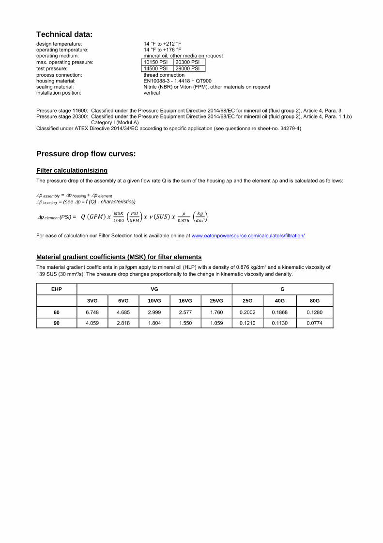
Technical data:
design temperature: 14 °F to +212 °F operating temperature: 14 °F to +176 °F operating medium: mineral oil, other media on request max. operating pressure: 10150 PSI 20300 PSI test pressure: 14500 PSI 29000 PSI process connection: thread connection housing material: EN10088-3 - 1.4418 + QT900 sealing material: Nitrile (NBR) or Viton (FPM), other materials on request installation position: vertical
Pressure stage 11600: Classified under the Pressure Equipment Directive 2014/68/EC for mineral oil (fluid group 2), Article 4, Para. 3. Pressure stage 20300: Classified under the Pressure Equipment Directive 2014/68/EC for mineral oil (fluid group 2), Article 4, Para. 1.1.b) Category I (Modul A) Classified under ATEX Directive 2014/34/EC according to specific application (see questionnaire sheet-no. 34279-4).
Pressure drop flow curves:
Filter calculation/sizing
The pressure drop of the assembly at a given flow rate Q is the sum of the housing ∆p and the element ∆p and is calculated as follows:
p assembly = p housing + p element p housing = (see p = f (Q) - characteristics)
p element (PSI) = .
³
For ease of calculation our Filter Selection tool is available online at www.eatonpowersource.com/calculators/filtration/
Material gradient coefficients (MSK) for filter elements
The material gradient coefficients in psi/gpm apply to mineral oil (HLP) with a density of 0.876 kg/dm³ and a kinematic viscosity of 139 SUS (30 mm²/s). The pressure drop changes proportionally to the change in kinematic viscosity and density.
EHP VG G
3VG 6VG 10VG 16VG 25VG 25G 40G 80G
60 6.748 4.685 2.999 2.577 1.760 0.2002 0.1868 0.1280
90 4.059 2.818 1.804 1.550 1.059 0.1210 0.1130 0.0774
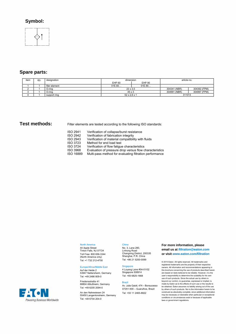
Symbol:
Spare parts:
item qty. designation dimension article-no. EHP 60 EHP 90
1 1 filer element 01E.60… 01E.90… 2 1 O-ring 22 x 3,5 304341 (NBR) 304392 (FPM) 3 1 O-ring 45 x 3 304991 (NBR) 304997 (FPM) 4 1 support ring 52 x 2,6 x 1 311013
Test methods: Filter elements are tested according to the following ISO standards:
ISO 2941 Verification of collapse/burst resistance ISO 2942 Verification of fabrication integrity ISO 2943 Verification of material compatibility with fluids ISO 3723 Method for end load test ISO 3724 Verification of flow fatigue characteristics ISO 3968 Evaluation of pressure drop versus flow characteristics ISO 16889 Multi-pass method for evaluating filtration performance
North America 44 Apple Street Tinton Falls, NJ 07724
Toll Free: 800 656-3344 (North America only)
Tel: +1 732 212-4700 Europe/Africa/Middle East Auf der Heide 2 53947 Nettersheim, Germany
Tel: +49 2486 809-0
Friedensstraße 41 68804 Altlußheim, Germany
Tel: +49 6205 2094-0
An den Nahewiesen 24 55450 Langenlonsheim, Germany
Tel: +49 6704 204-0
China No. 3, Lane 280, Linhong Road Changning District, 200335 Shanghai, P.R. China
Tel: +86 21 5200-0099 Singapore 4 Loyang Lane #04-01/02 Singapore 508914
Tel: +65 6825-1668 Brazil Av. Julia Gaioli, 474 – Bonsucesso 07251-500 – Guarulhos, Brazil
Tel: +55 11 2465-8822
For more information, please email us at [email protected]
or visit www.eaton.com/filtration
© 2015 Eaton. All rights reserved. All trademarks and registered trademarks are the property of their respective owners. All information and recommendations appearing in this brochure concerning the use of products described herein are based on tests believed to be reliable. However, it is the user’s responsibility to determine the suitability for his own use of such products. Since the actual use by others is beyond our control, no guarantee, expressed or implied, is made by Eaton as to the effects of such use or the results to be obtained. Eaton assumes no liability arising out of the use by others of such products. Nor is the information herein to be construed as absolutely complete, since additional information may be necessary or desirable when particular or exceptional conditions or circumstances exist or because of applicable laws or government regulations.

Series AS 220
SUCTION FILTER
Sheet No. 1903 J
EDV 09/15
Weight: approx. 10 lbs.
Dimensions: inches Designs and performance values are subject to change.
mounting surface surface quality flatness tolerance

Suction Filter
Series AS 220
Description:
The AS suction filters are horizontally or vertically mounted to the reservoir and connected directly to the suction-line. The filter housing consists of high quality aluminum material.
The filter element consists of a star-shaped, pleated filter material which is supported on the inside by a perforated core tube and is bonded to the end caps with a high-quality adhesive.
Eaton filter elements are known for a high intrinsic stability and an excellent filtration capability, a high dirt-retaining capacity and a long service life.
The suction filter is easy to service. When releasing the filter lid, a plate valve closes the suction-inlet of the filter and prevents the return flow of dirty oil to the reservoir. When mounted horizontally, it is not possible to drain the reservoir. After cleaning the element, the filter is ready for operation.
Eaton filter elements can be used for petroleum-based fluids, HW emulsions, water glycols, most synthetic fluids and lubrication fluids. Consult factory for specific fluid applications.
1. Type index:
1.1. Complete filter: (ordering example)
AS. 220. 40G. -. B. P. -. FS. 8. -. O1. -1 2 3 4 5 6 7 8 9 10 11 12
1 series: AS = suction filter
2 nominal size: 220
3 filter-material and filter-fineness: 40G stainless steel wire mesh
4 filter element collapse rating: - = not specified
5 filter element design: B = both sides open
6 sealing material: P = Nitrile (NBR) V = Viton (FPM)
7 filter element specification: - = standard VA = stainless steel
8 process connection: FS = SAE-flange 3000 PSI
9 no. of version: version 7 4 8 connection A type - FS FS size - 7 7 connection B type FS - FS size 8 - 8
type: FS = SAE-flange 3000 PSI size: - = no connection 7 = 1 ½” 8 = 2”
10 filter housing specification: - = standard
11 clogging indicator at M1: - = without O1 = visual, see sheet-no. 1616 E4.-0,25 = pressure switch, see sheet-no. 1616
12 clogging indicator at M2: possible indicators see position 11 of the type index
To add an indicator to your filter, use the corresponding indicator data sheet to find the indicator details and add them to the filter assembly model code.
1.2. Filter element: (ordering example)
01AS. 220. 40G. -. B. -. - 1 2 3 4 5 6 7
1 series: 01AS. = suction filter element according to company standard
2 nominal size: 220
3 - 5 / 7 see type index-complete filter
6 seling material: - = without
Accessories:
- SAE-counter flanges, see sheet-no. 1652

Technical data:
design temperature: 14 °F to +212 °F operating temperature: 14 °F to +176 °F operating medium mineral oil, other media on request process connection: SAE-flange 3000 PSI housing material: G-AlSi10Mgwa DIN 1725 (3.2381.61) sealing material: Nitrile (NBR) or Viton (FPM), other materials on request installation position: optional volume tank: .42 Gal.
Classified under the Pressure Equipment Directive 2014/68/EC for mineral oil (fluid group 2), Article 4, Para. 3. Classified under ATEX Directive 2014/34/EC according to specific application (see questionnaire sheet-no. 34279-4).
Pressure drop flow curves:
Filter calculation/sizing
The pressure drop of the assembly at a given flow rate Q is the sum of the housing ∆p and the element ∆p and is calculated as follows:
p assembly = p housing + p element p housing = (see p = f (Q) - characteristics)
p element (PSI) = .
³
For ease of calculation our Filter Selection tool is available online at www.eatonpowersource.com/calculators/filtration/
Material gradient coefficients (MSK) for filter elements
The material gradient coefficients in psi/gpm apply to mineral oil (HLP) with a density of 0.876 kg/dm³ and a kinematic viscosity of 139 SUS (30 mm²/s). The pressure drop changes proportionally to the change in kinematic viscosity and density.
AS G
40G
220 0.0491
∆p = f(Q) – characteristics according to ISO 3968
The pressure drop characteristics apply to mineral oil (HLP) with a density of 0.876 kg/dm³. The pressure drop changes proportionally to the density.

Symbols: without indicator visual O1 electrical E4.-0,25
Spare parts: item qty. designation dimension article-no.
1 1 filter element 01AS.220… 2 1 O-ring 75 x 3 302215 (NBR) 304729 (FPM) 3 1 O-ring 88 x 3 304417 (NBR) 310266 (FPM) 4 1 O-ring 96 x 4 305190 (NBR) 308148 (FPM) 5 1 O-ring 78 x 3,5 311610 (NBR) 314696 (FPM) 6 1 sliding ring 20165-4 305194 7 1 gasket .079 thick 305135 8 1 sliding ring 20164-4 305199 9 2 screw plug ½ BSPP 309730
10 2 gasket A 21 x 26 309815 11 1 clogging indicator, visual O1 301722 12 1 clogging indicator, electric E4.-0,25 301725
Test methods: Filter elements are tested according to the following ISO standards:
ISO 2941 Verification of collapse/burst resistance ISO 2942 Verification of fabrication integrity ISO 2943 Verification of material compatibility with fluids ISO 3723 Method for end load test ISO 3724 Verification of flow fatigue characteristics ISO 3968 Evaluation of pressure drop versus flow characteristics ISO 16889 Multi-pass method for evaluating filtration performance
North America 44 Apple Street Tinton Falls, NJ 07724
Toll Free: 800 656-3344 (North America only)
Tel: +1 732 212-4700 Europe/Africa/Middle East Auf der Heide 2 53947 Nettersheim, Germany
Tel: +49 2486 809-0
Friedensstraße 41 68804 Altlußheim, Germany
Tel: +49 6205 2094-0
An den Nahewiesen 24 55450 Langenlonsheim, Germany
Tel: +49 6704 204-0
China No. 3, Lane 280, Linhong Road Changning District, 200335 Shanghai, P.R. China
Tel: +86 21 5200-0099 Singapore 4 Loyang Lane #04-01/02 Singapore 508914
Tel: +65 6825-1668 Brazil Av. Julia Gaioli, 474 – Bonsucesso 07251-500 – Guarulhos, Brazil
Tel: +55 11 2465-8822
For more information, please email us at [email protected]
or visit www.eaton.com/filtration
© 2015 Eaton. All rights reserved. All trademarks and registered trademarks are the property of their respective owners. All information and recommendations appearing in this brochure concerning the use of products described herein are based on tests believed to be reliable. However, it is the user’s responsibility to determine the suitability for his own use of such products. Since the actual use by others is beyond our control, no guarantee, expressed or implied, is made by Eaton as to the effects of such use or the results to be obtained. Eaton assumes no liability arising out of the use by others of such products. Nor is the information herein to be construed as absolutely complete, since additional information may be necessary or desirable when particular or exceptional conditions or circumstances exist or because of applicable laws or government regulations.

Series AS 632
SUCTION FILTER
Sheet No. 1909 H
EDV 09/15
Weight: approx. 26 lbs.
Dimensions: inches Designs and performance values are subject to change.
mounting surface surface quality flatness tolerance
Dimensions:
connection size 2“ 2 ½“ 3“ 3 ½“ dimension A 3.07 3.50 4.18 4.76 dimension B 1.69 2.01 2.44 2.76 thread C M12,
.71 deep M12,
.71 deep M16,
.87 deep M16
.87 deep

Suction Filter
Series AS 632
Description:
The AS suction filters are horizontally or vertically mounted to the reservoir and connected directly to the suction-line. The filter housing consists of high quality aluminum material.
The filter element consists of a star-shaped, pleated filter material which is supported on the inside by a perforated core tube and is bonded to the end caps with a high-quality adhesive.
Eaton filter elements are known for a high intrinsic stability and an excellent filtration capability, a high dirt-retaining capacity and a long service life.
The suction filter is easy to service. When releasing the filter lid, a plate valve closes the suction-inlet of the filter and prevents the return flow of dirty oil to the reservoir. When mounted horizontally, it is not possible to drain the reservoir. After cleaning the element, the filter is ready for operation.
Eaton filter elements can be used for petroleum-based fluids, HW emulsions, water glycols, most synthetic fluids and lubrication fluids. Consult factory for specific fluid applications.
1. Type index:
1.1. Complete filter: (ordering example)
AS. 632. 40G. -. B. P. -. FS. 11. -. O11 2 3 4 5 6 7 8 9 10 11
1 series: AS = suction filter
2 nominal size: 632
3 filter-material and filter-fineness: 40G stainless steel wire mesh
4 filter element collapse rating: - = not specified
5 filter element design: B = both sides open
6 sealing material: P = Nitrile (NBR) V = Viton (FPM)
7 filter element specification: - = standard VA = stainless steel
8 process connection: FS = SAE-flange 3000 PSI
9 no. of version: version 1 5 6 10 11 12 14 21 connection A type XY XY XY FS FS FS - FS size A1 A1 A1 A connection B type Y M M FS FS - FS Y size 8 9 8 connection C type FS FS FS Y Y Y FS Y size 8 9 9 8 connection D type FS FS - Y M M FS FS size 8 9 8 8
type: FS = SAE-flange 3000 PSI size: 8 = 2” M = adapter M18x1,5 – R1/8 9 = 2 ½” Y = drain M18x1,5 A = 3” X = adapter SAE 3” – M18x1,5 A1 = 3 ½” - = no connection
10 filter housing specification: - = standard
11 clogging indicator at M1: - = without O1 = visual, see sheet-no. 1616 E4.-0,25 = pressure switch, see sheet-no. 1616
To add an indicator to your filter, use the corresponding indicator data sheet to find the indicator details and add them to the filter assembly model code.
1.2. Filter element: (ordering example)
01AS. 631. 40G. -. B. -. - 1 2 3 4 5 6 7
1 series: 01AS. = suction filter element according to company standard
2 nominal size: 631
3 - 5 / 7 see type index-complete filter
6 seling material: - = without
Accessories:

Technical data:
design temperature: 14 °F to +212 °F operating temperature: 14 °F to +176 °F operating medium mineral oil, other media on request process connection: SAE-flange 3000 PSI housing material: G-AlSi10Mgwa DIN 1725 (3.2381.61) sealing material: Nitrile (NBR) or Viton (FPM), other materials on request installation position: optional volume tank: 1.6 Gal.
Classified under the Pressure Equipment Directive 2014/68/EC for mineral oil (fluid group 2), Article 4, Para. 3. Classified under ATEX Directive 2014/34/EC according to specific application (see questionnaire sheet-no. 34279-4).
Pressure drop flow curves:
Filter calculation/sizing
The pressure drop of the assembly at a given flow rate Q is the sum of the housing ∆p and the element ∆p and is calculated as follows:
p assembly = p housing + p element p housing = (see p = f (Q) - characteristics)
p element (PSI) = .
³
For ease of calculation our Filter Selection tool is available online at www.eatonpowersource.com/calculators/filtration/
Material gradient coefficients (MSK) for filter elements
The material gradient coefficients in psi/gpm apply to mineral oil (HLP) with a density of 0.876 kg/dm³ and a kinematic viscosity of 139 SUS (30 mm²/s). The pressure drop changes proportionally to the change in kinematic viscosity and density.
AS G
40G
632 0.0193
∆p = f(Q) – characteristics according to ISO 3968
The pressure drop characteristics apply to mineral oil (HLP) with a density of 0.876 kg/dm³. The pressure drop changes proportionally to the density.

Symbols: without indicator visual O1 electrical E4.-0,25
Spare parts: item qty. designation dimension article-no.
1 1 filter element 01AS.631… 2 1 O-ring 115 x 3 303963 (NBR) 307762 (FPM) 3 1 O-ring 125 x 3 306025 (NBR) 307358 (FPM) 4 1 O-ring 115 x 5 306640 (NBR) 310287 (FPM) 5 1 O-ring 104,37 x 3,53 304339 (NBR) 304390 (FPM) 6 1 gasket .078 thick 305160 7 1 adapter M18 x 1,5 - 1/8 BSPP 30505-4 317114 8 2 gasket A18 x 24x1,5 305136 9 1 clogging indicator, visual O1 301722
10 1 clogging indicator, electrical E4.-0,25 301725 11 1 O-ring 85,32 x 3,53 305590 (NBR) 306308 (FPM) 12 1 adapter SAE 3“ - M18 x 1,5 30294-3 317048 13 1 screw plug M18 x 1,5 305193
Test methods: Filter elements are tested according to the following ISO standards:
ISO 2941 Verification of collapse/burst resistance ISO 2942 Verification of fabrication integrity ISO 2943 Verification of material compatibility with fluids ISO 3723 Method for end load test ISO 3724 Verification of flow fatigue characteristics ISO 3968 Evaluation of pressure drop versus flow characteristics ISO 16889 Multi-pass method for evaluating filtration performance
North America 44 Apple Street Tinton Falls, NJ 07724
Toll Free: 800 656-3344 (North America only)
Tel: +1 732 212-4700 Europe/Africa/Middle East Auf der Heide 2 53947 Nettersheim, Germany
Tel: +49 2486 809-0
Friedensstraße 41 68804 Altlußheim, Germany
Tel: +49 6205 2094-0
An den Nahewiesen 24 55450 Langenlonsheim, Germany
Tel: +49 6704 204-0
China No. 3, Lane 280, Linhong Road Changning District, 200335 Shanghai, P.R. China
Tel: +86 21 5200-0099 Singapore 4 Loyang Lane #04-01/02 Singapore 508914
Tel: +65 6825-1668 Brazil Av. Julia Gaioli, 474 – Bonsucesso 07251-500 – Guarulhos, Brazil
Tel: +55 11 2465-8822
For more information, please email us at [email protected]
or visit www.eaton.com/filtration
© 2015 Eaton. All rights reserved. All trademarks and registered trademarks are the property of their respective owners. All information and recommendations appearing in this brochure concerning the use of products described herein are based on tests believed to be reliable. However, it is the user’s responsibility to determine the suitability for his own use of such products. Since the actual use by others is beyond our control, no guarantee, expressed or implied, is made by Eaton as to the effects of such use or the results to be obtained. Eaton assumes no liability arising out of the use by others of such products. Nor is the information herein to be construed as absolutely complete, since additional information may be necessary or desirable when particular or exceptional conditions or circumstances exist or because of applicable laws or government regulations.

Series TS 210-310
SUCTION FILTER, vertical tank mounted
Sheet No. 1904 J
EDV 09/15
Dimensions: inches Designs and performance values are subject to change.
Dimensions:
type TS 210 TS 310 connection - 20 SAE -20 SAE
A 12.09 15.47 B 11.57 14.96 C 11.42 14.76 D 8.62 12.00 E .26 .30
weight 5.10 lbs. 6.60 lbs. volume tank .30 Gal. .40 Gal.

1. Type index:
1.1. Complete filter: (ordering example)
TS. 210. 10VG. -. B. P. -. UG. 6. -. -. O1. E41 2 3 4 5 6 7 8 9 10 11 12 13
1 series: TS = suction filter for vertical tank-mounting
2 nominal size: 210, 310
3 filter-material and filter-fineness: 80G, 40G, 25G stainless steel wire mesh 25VG, 16VG, 10VG, 6VG, 3VG microglass 10P paper
4 resistance of pressure difference for filter element: - = not specified
5 filter element design: B = both sides open
6 sealing material: P = Nitrile (NBR) V = Viton (FPM)
7 filter element specification: - = standard VA = stainless steel
8 process connection: UG = thread connection
9 process connection size: 6 = -20 SAE
10 filter housing specification: - = standard
11 internal valve: - = without S = with by-pass valve p 4.1 PSI
12 clogging indicator at M1: - = without O1 = visual, see sheet-no. 1616 E4 = pressure switch, see sheet-no. 1616
13 clogging indicator at M2: possible indicators see position 12 of the type index
To add an indicator to your filter, use the corresponding indicator data sheet to find the indicator details and add them to the filter assembly model code.
1.2. Filter element: (ordering example)
01TS. 210. 10VG. -. B. -. - 1 2 3 4 5 6 7
1 series: 01TS. = suction filter element according to company standard
2 nominal size: 210, 310
3 - 5 / 7 see type index-complete filter
6 seling material: - = without
Suction Filter
Series TS 210-310
Description:
The TS-filters are directly mounted to the reservoir and connected to the suction-line. The suction inlet connection must be below the oil level.
The filter element consists of star-shaped, pleated filter material, which is supported on the inside by a perforated core tube and is bonded to the end caps with a high-quality adhesive. The flow direction is from outside to inside.
Eaton filter elements are known for a high intrinsic stability and an excellent filtration capability, a high dirt-retaining capacity and a long service life.
For filtration finer than 40 μm use the disposable elements made of microglass. Filter elements as fine as 5 μm(c) are available; finer filter elements on request.
Eaton filter elements can be used for petroleum-based fluids, HW emulsions, water glycols, most synthetic fluids and lubrication fluids. Consult factory for specific fluid applications.
When removing the filter cover, a plate-shaped valve closes the suction-inlet of the filter bowl and prevents dirty oil from flowing into the tank. For cleaning, the filter bowl and the filter element can be taken out of the filter head.

Technical data:
design temperature: 14 °F to +212 °F operating temperature: 14 °F to +176 °F operating medium mineral oil, other media on request process connection: thread connection housing material: Al-casting, glass fiber reinforced polyamide sealing material: Nitrile (NBR) or Viton (FPM), other materials on request installation position: vertical
Classified under the Pressure Equipment Directive 2014/68/EC for mineral oil (fluid group 2), Article 4, Para. 3. Classified under ATEX Directive 2014/34/EC according to specific application (see questionnaire sheet-no. 34279-4).
Pressure drop flow curves:
Filter calculation/sizing
The pressure drop of the assembly at a given flow rate Q is the sum of the housing ∆p and the element ∆p and is calculated as follows:
p assembly = p housing + p element p housing = (see p = f (Q) - characteristics)
p element (PSI) = .
³
For ease of calculation our Filter Selection tool is available online at www.eatonpowersource.com/calculators/filtration/
Material gradient coefficients (MSK) for filter elements
The material gradient coefficients in psi/gpm apply to mineral oil (HLP) with a density of 0.876 kg/dm³ and a kinematic viscosity of 139 SUS (30 mm²/s). The pressure drop changes proportionally to the change in kinematic viscosity and density.
TS VG G P
3VG 6VG 10VG 16VG 25VG 25G 40G 80G 10P
210 2.250 1.562 1.000 0.871 0.595 0.0826 0.0612 0.0571 0.443
310 1.628 1.130 0.724 0.630 0.430 0.0598 0.0443 0.0413 0.321
∆p = f(Q) – characteristics according to ISO 3968
The pressure drop characteristics apply to mineral oil (HLP) with a density of 0.876 kg/dm³. The pressure drop changes proportionally to the density.

Symbols:
without indicator
visual O
electric E4
filter without internal valve
filter with internal valve
Spare parts: item qty. designation dimension article-no.
TS 210 TS 310 1 1 filter element 01TS.210… 01TS.310… 2 1 filter head 304423 3 1 filter bowl 304518.1 4 1 filter cover M 90 x 2 5 1 O-ring 53 x 4 309143 (NBR) 332434 (FPM) 6 1 O-ring 62 x 4 308045 (NBR) 311472 (FPM) 7 1 O-ring 75 x 3 302215 (NBR) 304729 (FPM) 8 1 O-ring 82 x 3 305191 (NBR) 305298 (FPM) 9 1 O-ring 88 x 3 304417 (NBR) 310266 (FPM)
10 1 sheet metal screw B 6,3 x 13 316641 11 1 clogging indicator, visual O1 301722 12 1 pressure switch, electric E4 311016
Test methods: Filter elements are tested according to the following ISO standards:
ISO 2941 Verification of collapse/burst resistance ISO 2942 Verification of fabrication integrity ISO 2943 Verification of material compatibility with fluids ISO 3723 Method for end load test ISO 3724 Verification of flow fatigue characteristics ISO 3968 Evaluation of pressure drop versus flow characteristics ISO 16889 Multi-pass method for evaluating filtration performance
North America 44 Apple Street Tinton Falls, NJ 07724
Toll Free: 800 656-3344 (North America only)
Tel: +1 732 212-4700 Europe/Africa/Middle East Auf der Heide 2 53947 Nettersheim, Germany
Tel: +49 2486 809-0
Friedensstraße 41 68804 Altlußheim, Germany
Tel: +49 6205 2094-0
An den Nahewiesen 24 55450 Langenlonsheim, Germany
Tel: +49 6704 204-0
China No. 3, Lane 280, Linhong Road Changning District, 200335 Shanghai, P.R. China
Tel: +86 21 5200-0099 Singapore 4 Loyang Lane #04-01/02 Singapore 508914
Tel: +65 6825-1668 Brazil Av. Julia Gaioli, 474 – Bonsucesso 07251-500 – Guarulhos, Brazil
Tel: +55 11 2465-8822
For more information, please email us at [email protected]
or visit www.eaton.com/filtration
© 2015 Eaton. All rights reserved. All trademarks and registered trademarks are the property of their respective owners. All information and recommendations appearing in this brochure concerning the use of products described herein are based on tests believed to be reliable. However, it is the user’s responsibility to determine the suitability for his own use of such products. Since the actual use by others is beyond our control, no guarantee, expressed or implied, is made by Eaton as to the effects of such use or the results to be obtained. Eaton assumes no liability arising out of the use by others of such products. Nor is the information herein to be construed as absolutely complete, since additional information may be necessary or desirable when particular or exceptional conditions or circumstances exist or because of applicable laws or government regulations.

Series TS 426
SUCTION FILTER, vertical tank mounted
Sheet No. 1908 F
EDV 09/15
Weight: approx. 12.5 lbs.
Dimensions: inches Designs and performance values are subject to change.
1) The bypass valve is contained in the screw plug. For filters without a by-pass valve, the opening pressure is p 14.5 PSI.
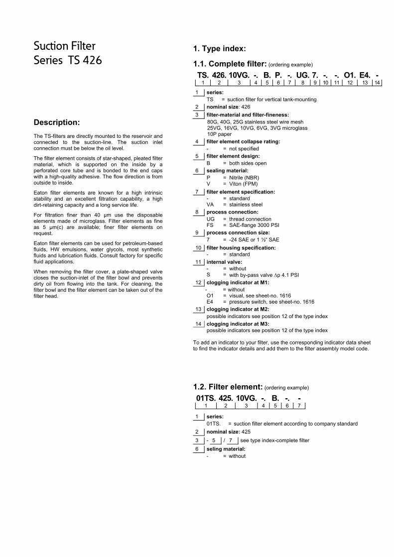
Suction Filter
Series TS 426
Description:
The TS-filters are directly mounted to the reservoir and connected to the suction-line. The suction inlet connection must be below the oil level.
The filter element consists of star-shaped, pleated filter material, which is supported on the inside by a perforated core tube and is bonded to the end caps with a high-quality adhesive. The flow direction is from outside to inside.
Eaton filter elements are known for a high intrinsic stability and an excellent filtration capability, a high dirt-retaining capacity and a long service life.
For filtration finer than 40 μm use the disposable elements made of microglass. Filter elements as fine as 5 μm(c) are available; finer filter elements on request.
Eaton filter elements can be used for petroleum-based fluids, HW emulsions, water glycols, most synthetic fluids and lubrication fluids. Consult factory for specific fluid applications.
When removing the filter cover, a plate-shaped valve closes the suction-inlet of the filter bowl and prevents dirty oil from flowing into the tank. For cleaning, the filter bowl and the filter element can be taken out of the filter head.
1. Type index:
1.1. Complete filter: (ordering example)
TS. 426. 10VG. -. B. P. -. UG. 7. -. -. O1. E4. -1 2 3 4 5 6 7 8 9 10 11 12 13 14
1 series: TS = suction filter for vertical tank-mounting
2 nominal size: 426
3 filter-material and filter-fineness: 80G, 40G, 25G stainless steel wire mesh 25VG, 16VG, 10VG, 6VG, 3VG microglass 10P paper
4 filter element collapse rating: - = not specified
5 filter element design: B = both sides open
6 sealing material: P = Nitrile (NBR) V = Viton (FPM)
7 filter element specification: - = standard VA = stainless steel
8 process connection: UG = thread connection FS = SAE-flange 3000 PSI
9 process connection size: 7 = -24 SAE or 1 ½“ SAE
10 filter housing specification: - = standard
11 internal valve: - = without S = with by-pass valve p 4.1 PSI
12 clogging indicator at M1: - = without O1 = visual, see sheet-no. 1616 E4 = pressure switch, see sheet-no. 1616
13 clogging indicator at M2: possible indicators see position 12 of the type index
14 clogging indicator at M3: possible indicators see position 12 of the type index
To add an indicator to your filter, use the corresponding indicator data sheet to find the indicator details and add them to the filter assembly model code.
1.2. Filter element: (ordering example)
01TS. 425. 10VG. -. B. -. - 1 2 3 4 5 6 7
1 series: 01TS. = suction filter element according to company standard
2 nominal size: 425
3 - 5 / 7 see type index-complete filter
6 seling material: - = without

Technical data:
design temperature: 14 °F to +212 °F operating temperature: 14 °F to +176 °F operating medium mineral oil, other media on request process connection: thread connection or SAE-flange 3000 PSI housing material: Al-casting, glass fiber reinforced polyamide sealing material: Nitrile (NBR) or Viton (FPM), other materials on request installation position: vertical volume tank: .70 Gal.
Classified under the Pressure Equipment Directive 2014/68/EC for mineral oil (fluid group 2), Article 4, Para. 3. Classified under ATEX Directive 2014/34/EC according to specific application (see questionnaire sheet-no. 34279-4).
Pressure drop flow curves:
Filter calculation/sizing
The pressure drop of the assembly at a given flow rate Q is the sum of the housing ∆p and the element ∆p and is calculated as follows:
p assembly = p housing + p element p housing = (see p = f (Q) - characteristics)
p element (PSI) = .
³
For ease of calculation our Filter Selection tool is available online at www.eatonpowersource.com/calculators/filtration/
Material gradient coefficients (MSK) for filter elements
The material gradient coefficients in psi/gpm apply to mineral oil (HLP) with a density of 0.876 kg/dm³ and a kinematic viscosity of 139 SUS (30 mm²/s). The pressure drop changes proportionally to the change in kinematic viscosity and density.
TS VG G P
3VG 6VG 10VG 16VG 25VG 25G 40G 80G 10P
426 0.887 0.616 0.394 0.343 0.235 0.0226 0.0211 0.0144 0.188
∆p = f(Q) – characteristics according to ISO 3968
The pressure drop characteristics apply to mineral oil (HLP) with a density of 0.876 kg/dm³. The pressure drop changes proportionally to the density.

Symbols:
without indicator
visual O
electric E4
filter without internal valve
filter with internal valve
Spare parts: item qty. designation dimension article-no.
1 1 filter element 01TS.425… 2 1 filter head NG 426 3 1 filter bowl NG 426 4 1 screw plug with by-pass M 120 x 3 1 screw plug without by-pass M 120 x 3
5 1 valve disc 311892 6 1 valve bushing 307548 7 1 O-ring 128 x 3 304602 (NBR) 308140 (FPM) 8 1 O-ring 115 x 3 303963 (NBR) 307762 (FPM) 9 1 O-ring 98 x 4 301914 (NBR) 304765 (FPM)
10 1 O-ring 70 x 4 306253 (NBR) 310280 (FPM) 11 2 O-ring 76 x 4 305599 (NBR) 310291 (FPM) 12 1 sliding ring 307547 13 1 pressure ring 307549 14 1 fillister head cap screw M 6 x 60 307534 15 1 spring 1,6 x 10 x 53 x 12.5 311847 16 1 O-ring 50 x 3 307398 (NBR) 314682 (FPM) 17 1 clogging indicator, visual O1 301722 18 1 clogging indicator, electric E4 311016
Test methods: Filter elements are tested according to the following ISO standards:
ISO 2941 Verification of collapse/burst resistance ISO 2942 Verification of fabrication integrity ISO 2943 Verification of material compatibility with fluids ISO 3723 Method for end load test ISO 3724 Verification of flow fatigue characteristics ISO 3968 Evaluation of pressure drop versus flow characteristics ISO 16889 Multi-pass method for evaluating filtration performance
North America 44 Apple Street Tinton Falls, NJ 07724
Toll Free: 800 656-3344 (North America only)
Tel: +1 732 212-4700 Europe/Africa/Middle East Auf der Heide 2 53947 Nettersheim, Germany
Tel: +49 2486 809-0
Friedensstraße 41 68804 Altlußheim, Germany
Tel: +49 6205 2094-0
An den Nahewiesen 24 55450 Langenlonsheim, Germany
Tel: +49 6704 204-0
China No. 3, Lane 280, Linhong Road Changning District, 200335 Shanghai, P.R. China
Tel: +86 21 5200-0099 Singapore 4 Loyang Lane #04-01/02 Singapore 508914
Tel: +65 6825-1668 Brazil Av. Julia Gaioli, 474 – Bonsucesso 07251-500 – Guarulhos, Brazil
Tel: +55 11 2465-8822
For more information, please email us at [email protected]
or visit www.eaton.com/filtration
© 2015 Eaton. All rights reserved. All trademarks and registered trademarks are the property of their respective owners. All information and recommendations appearing in this brochure concerning the use of products described herein are based on tests believed to be reliable. However, it is the user’s responsibility to determine the suitability for his own use of such products. Since the actual use by others is beyond our control, no guarantee, expressed or implied, is made by Eaton as to the effects of such use or the results to be obtained. Eaton assumes no liability arising out of the use by others of such products. Nor is the information herein to be construed as absolutely complete, since additional information may be necessary or desirable when particular or exceptional conditions or circumstances exist or because of applicable laws or government regulations.
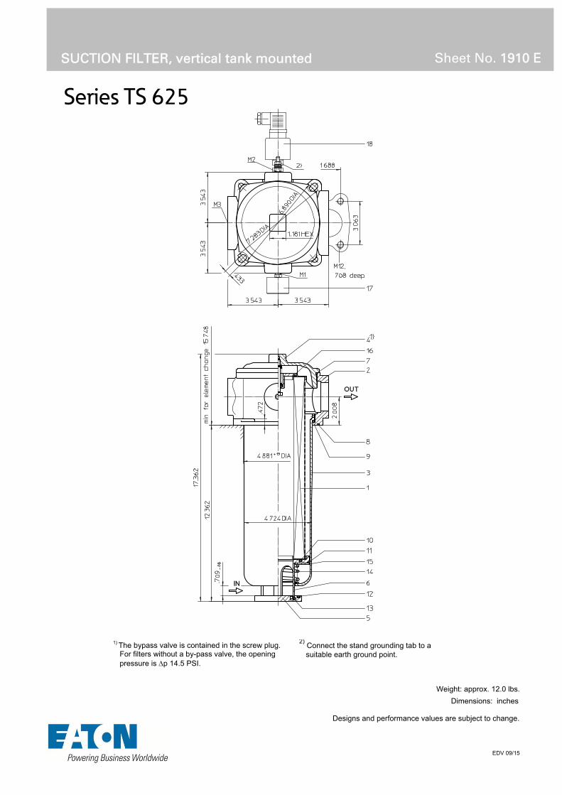
Series TS 625
EDV 09/15
SUCTION FILTER, vertical tank mounted
Sheet No. 1910 E
Weight: approx. 12.0 lbs.
Dimensions: inches Designs and performance values are subject to change.
1) The bypass valve is contained in the screw plug. For filters without a by-pass valve, the opening pressure is p 14.5 PSI.
2) Connect the stand grounding tab to a
suitable earth ground point.

Suction Filter
Series TS 625
Description:
The TS-filters are directly mounted to the reservoir and connected to the suction-line. The suction inlet connection must be below the oil level.
The filter element consists of star-shaped, pleated filter material, which is supported on the inside by a perforated core tube and is bonded to the end caps with a high-quality adhesive. The flow direction is from outside to inside.
Eaton filter elements are known for a high intrinsic stability and an excellent filtration capability, a high dirt-retaining capacity and a long service life.
For filtration finer than 40 μm use the disposable elements made of microglass. Filter elements as fine as 5 μm(c) are available; finer filter elements on request.
Eaton filter elements can be used for petroleum-based fluids, HW emulsions, water glycols, most synthetic fluids and lubrication fluids. Consult factory for specific fluid applications.
When removing the filter cover, a plate-shaped valve closes the suction-inlet of the filter bowl and prevents dirty oil from flowing into the tank. For cleaning, the filter bowl and the filter element can be taken out of the filter head.
1. Type index:
1.1. Complete filter: (ordering example)
TS. 625. 10VG. -. B. P. -. FS. 8. -. -. O1. E4. -1 2 3 4 5 6 7 8 9 10 11 12 13 14
1 series: TS = suction filter for vertical tank-mounting
2 nominal size: 625
3 filter-material and filter-fineness: 80G, 40G, 25G stainless steel wire mesh 25VG, 16VG, 10VG, 6VG, 3VG microglass 10P paper
4 filter element collapse rating: - = not specified
5 filter element design: B = both sides open
6 sealing material: P = Nitrile (NBR) V = Viton (FPM)
7 filter element specification: - = standard VA = stainless steel
8 process connection: FS = SAE-flange 3000 PSI
9 process connection size: 8 = 2“
10 filter housing specification: - = standard IS11 = for filter head and filter cover, see sheet-no. 40530
11 internal valve: - = without S = with by-pass valve p 4.1 PSI
12 clogging indicator at M1: - = without O1 = visual, see sheet-no. 1616 E4 = pressure switch, see sheet-no. 1616 PA = ground connection
13 clogging indicator at M2: possible indicators see position 12 of the type index
14 clogging indicator at M3: possible indicators see position 12 of the type index
1.2. Filter element: (ordering example)
01TS. 625. 10VG. -. B. -. - 1 2 3 4 5 6 7
1 series: 01TS. = suction filter element according to company standard
2 nominal size: 625
3 - 5 / 7 see type index-complete filter
6 seling material: - = without

Technical data:
design temperature: 14 °F to +212 °F operating temperature: 14 °F to +176 °F operating medium mineral oil, other media on request process connection: SAE-flange 3000 PSI housing material standard: filter head, filter cover AL / filter bowl glass fibre reinforced polyamide housing material IS11: filter head, filter cover GG / filter bowl carbon fibre reinforced polyamide sealing material: Nitrile (NBR) or Viton (FPM), other materials on request installation position: vertical volume tank: 1.0 Gal.
Classified under the Pressure Equipment Directive 2014/68/EC for mineral oil (fluid group 2), Article 4, Para. 3. Classified under ATEX Directive 2014/34/EC according to specific application (see questionnaire sheet-no. 34279-4).
Pressure drop flow curves:
Filter calculation/sizing
The pressure drop of the assembly at a given flow rate Q is the sum of the housing ∆p and the element ∆p and is calculated as follows:
p assembly = p housing + p element p housing = (see p = f (Q) - characteristics)
p element (PSI) = .
³
For ease of calculation our Filter Selection tool is available online at www.eatonpowersource.com/calculators/filtration/
Material gradient coefficients (MSK) for filter elements
The material gradient coefficients in psi/gpm apply to mineral oil (HLP) with a density of 0.876 kg/dm³ and a kinematic viscosity of 139 SUS (30 mm²/s). The pressure drop changes proportionally to the change in kinematic viscosity and density.
TS VG G P
3VG 6VG 10VG 16VG 25VG 25G 40G 80G 10P
625 0.733 0.509 0.326 0.284 0.194 0.0170 0.0159 0.0109 0.160
∆p = f(Q) – characteristics according to ISO 3968
The pressure drop characteristics apply to mineral oil (HLP) with a density of 0.876 kg/dm³. The pressure drop changes proportionally to the density.

Symbols:
without indicator
visual O
electric E4
filter without internal valve
filter with internal valve
Spare parts: item qty. designation dimension article-no.
1 1 filter element 01TS.625… 2 1 filter head NG 625 3 1 filter bowl NG 625 4 1 screw plug with by-pass valve M 140 x 3 1 screw plug without by-pass valve M 140 x 3
5 1 valve disc 318740 6 1 valve bushing 318739 7 1 O-ring 135 x 3,5 318386 (NBR) 318387 (FPM) 8 1 O-ring 140 x 3 304604 (NBR) 307514 (FPM) 9 1 O-ring 120 x 4 305300 (NBR) 307991 (FPM)
10 1 O-ring 76 x 4 305599 (NBR) 310291 (FPM) 11 1 O-ring 104,37 x 3,53 304339 (NBR) 304390 (FPM) 12 1 O-ring 70 x 4 306253 (NBR) 310280 (FPM) 13 1 snap ring B 55 311976 14 1 spring 5,0 x 70 x 117 x 3,5 318742 15 1 disc 318741 16 1 O-ring 56 x 3 307398 (NBR) 314682 (FPM) 17 1 clogging indicator, visual E4 311016 18 1 clogging indicator, electrical O1 301722
Test methods: Filter elements are tested according to the following ISO standards:
ISO 2941 Verification of collapse/burst resistance ISO 2942 Verification of fabrication integrity ISO 2943 Verification of material compatibility with fluids ISO 3723 Method for end load test ISO 3724 Verification of flow fatigue characteristics ISO 3968 Evaluation of pressure drop versus flow characteristics ISO 16889 Multi-pass method for evaluating filtration performance
North America 44 Apple Street Tinton Falls, NJ 07724
Toll Free: 800 656-3344 (North America only)
Tel: +1 732 212-4700 Europe/Africa/Middle East Auf der Heide 2 53947 Nettersheim, Germany
Tel: +49 2486 809-0
Friedensstraße 41 68804 Altlußheim, Germany
Tel: +49 6205 2094-0
An den Nahewiesen 24 55450 Langenlonsheim, Germany
Tel: +49 6704 204-0
China No. 3, Lane 280, Linhong Road Changning District, 200335 Shanghai, P.R. China
Tel: +86 21 5200-0099 Singapore 4 Loyang Lane #04-01/02 Singapore 508914
Tel: +65 6825-1668 Brazil Av. Julia Gaioli, 474 – Bonsucesso 07251-500 – Guarulhos, Brazil
Tel: +55 11 2465-8822
For more information, please email us at [email protected]
or visit www.eaton.com/filtration
© 2015 Eaton. All rights reserved. All trademarks and registered trademarks are the property of their respective owners. All information and recommendations appearing in this brochure concerning the use of products described herein are based on tests believed to be reliable. However, it is the user’s responsibility to determine the suitability for his own use of such products. Since the actual use by others is beyond our control, no guarantee, expressed or implied, is made by Eaton as to the effects of such use or the results to be obtained. Eaton assumes no liability arising out of the use by others of such products. Nor is the information herein to be construed as absolutely complete, since additional information may be necessary or desirable when particular or exceptional conditions or circumstances exist or because of applicable laws or government regulations.

Series TSW 210-310
SUCTION FILTER, horizontal tank mounted
Sheet No. 1905 J
EDV 09/15
Dimensions: inches Designs and performance values are subject to change.
Dimensions:
type TSW 210 TSW 310 connection - 20 SAE -20 SAE
A 12.09 15.47 B 11.57 14.96 C 11.42 14.76 D 8.62 12.00 E .26 .30
weight 5.10 lbs. 6.60 lbs. volume tank .30 Gal. .40 Gal.
mounting surface surface quality flatness tolerance
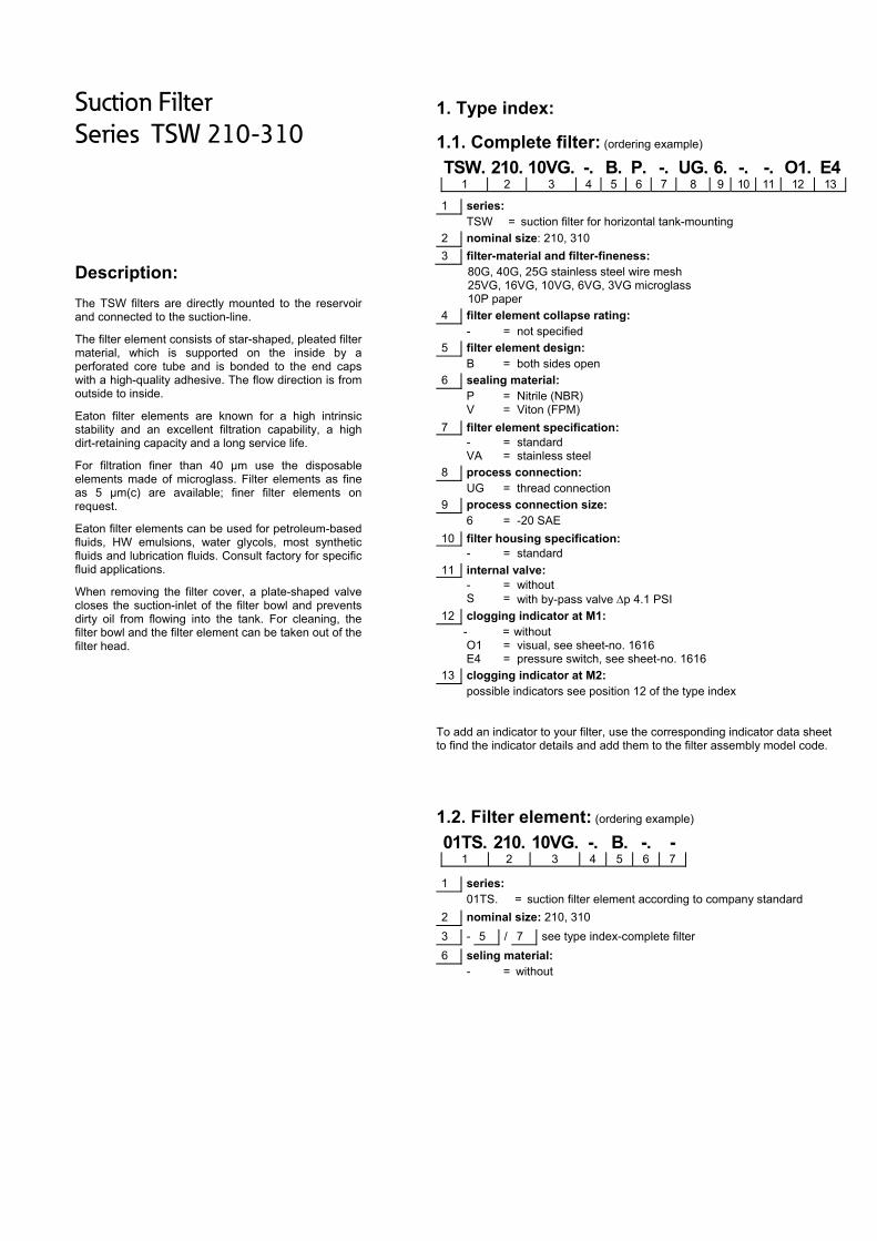
Suction Filter
Series TSW 210-310
Description:
The TSW filters are directly mounted to the reservoir and connected to the suction-line.
The filter element consists of star-shaped, pleated filter material, which is supported on the inside by a perforated core tube and is bonded to the end caps with a high-quality adhesive. The flow direction is from outside to inside.
Eaton filter elements are known for a high intrinsic stability and an excellent filtration capability, a high dirt-retaining capacity and a long service life.
For filtration finer than 40 μm use the disposable elements made of microglass. Filter elements as fine as 5 μm(c) are available; finer filter elements on request.
Eaton filter elements can be used for petroleum-based fluids, HW emulsions, water glycols, most synthetic fluids and lubrication fluids. Consult factory for specific fluid applications.
When removing the filter cover, a plate-shaped valve closes the suction-inlet of the filter bowl and prevents dirty oil from flowing into the tank. For cleaning, the filter bowl and the filter element can be taken out of the filter head.
1. Type index:
1.1. Complete filter: (ordering example)
TSW. 210. 10VG. -. B. P. -. UG. 6. -. -. O1. E41 2 3 4 5 6 7 8 9 10 11 12 13
1 series: TSW = suction filter for horizontal tank-mounting
2 nominal size: 210, 310
3 filter-material and filter-fineness: 80G, 40G, 25G stainless steel wire mesh 25VG, 16VG, 10VG, 6VG, 3VG microglass 10P paper
4 filter element collapse rating: - = not specified
5 filter element design: B = both sides open
6 sealing material: P = Nitrile (NBR) V = Viton (FPM)
7 filter element specification: - = standard VA = stainless steel
8 process connection: UG = thread connection
9 process connection size: 6 = -20 SAE
10 filter housing specification: - = standard
11 internal valve: - = without S = with by-pass valve p 4.1 PSI
12 clogging indicator at M1: - = without O1 = visual, see sheet-no. 1616 E4 = pressure switch, see sheet-no. 1616
13 clogging indicator at M2: possible indicators see position 12 of the type index
To add an indicator to your filter, use the corresponding indicator data sheet to find the indicator details and add them to the filter assembly model code.
1.2. Filter element: (ordering example)
01TS. 210. 10VG. -. B. -. - 1 2 3 4 5 6 7
1 series: 01TS. = suction filter element according to company standard
2 nominal size: 210, 310
3 - 5 / 7 see type index-complete filter
6 seling material: - = without

Technical data:
design temperature: 14 °F to +212 °F operating temperature: 14 °F to +176 °F operating medium mineral oil, other media on request process connection: thread connection housing material: Al-casting, glass fiber reinforced polyamide sealing material: Nitrile (NBR) or Viton (FPM), other materials on request installation position: vertical
Classified under the Pressure Equipment Directive 2014/68/EC for mineral oil (fluid group 2), Article 4, Para. 3. Classified under ATEX Directive 2014/34/EC according to specific application (see questionnaire sheet-no. 34279-4).
Pressure drop flow curves:
Filter calculation/sizing
The pressure drop of the assembly at a given flow rate Q is the sum of the housing ∆p and the element ∆p and is calculated as follows:
p assembly = p housing + p element p housing = (see p = f (Q) - characteristics)
p element (PSI) = .
³
For ease of calculation our Filter Selection tool is available online at www.eatonpowersource.com/calculators/filtration/
Material gradient coefficients (MSK) for filter elements
The material gradient coefficients in psi/gpm apply to mineral oil (HLP) with a density of 0.876 kg/dm³ and a kinematic viscosity of 139 SUS (30 mm²/s). The pressure drop changes proportionally to the change in kinematic viscosity and density.
TSW VG G P
3VG 6VG 10VG 16VG 25VG 25G 40G 80G 10P
210 2.250 1.562 1.000 0.871 0.595 0.0826 0.0612 0.0571 0.443
310 1.628 1.130 0.724 0.630 0.430 0.0598 0.0443 0.0413 0.321
∆p = f(Q) – characteristics according to ISO 3968
The pressure drop characteristics apply to mineral oil (HLP) with a density of 0.876 kg/dm³. The pressure drop changes proportionally to the density.

Symbols:
without indicator
visual O
electric E4
filter without internal valve
filter with internal valve
Spare parts: item qty. designation dimension article-no.
TSW 210 TSW 310 1 1 filter element 01TS.210… 01TS.310… 2 1 filter head 304423 3 1 filter bowl 304518.1 4 1 filter cover M 90 x 2 5 1 O-ring 53 x 4 309143 (NBR) 332434 (FPM) 6 1 O-ring 62 x 4 308045 (NBR) 311472 (FPM) 7 1 O-ring 75 x 3 302215 (NBR) 304729 (FPM) 8 1 O-ring 82 x 3 305191 (NBR) 305298 (FPM) 9 1 O-ring 88 x 3 304417 (NBR) 310266 (FPM)
10 1 sheet metal screw B 6,3 x 13 316641 11 1 clogging indicator, visual O1 301722 12 1 pressure switch, electric E4 311016
Test methods: Filter elements are tested according to the following ISO standards:
ISO 2941 Verification of collapse/burst resistance ISO 2942 Verification of fabrication integrity ISO 2943 Verification of material compatibility with fluids ISO 3723 Method for end load test ISO 3724 Verification of flow fatigue characteristics ISO 3968 Evaluation of pressure drop versus flow characteristics ISO 16889 Multi-pass method for evaluating filtration performance
North America 44 Apple Street Tinton Falls, NJ 07724
Toll Free: 800 656-3344 (North America only)
Tel: +1 732 212-4700 Europe/Africa/Middle East Auf der Heide 2 53947 Nettersheim, Germany
Tel: +49 2486 809-0
Friedensstraße 41 68804 Altlußheim, Germany
Tel: +49 6205 2094-0
An den Nahewiesen 24 55450 Langenlonsheim, Germany
Tel: +49 6704 204-0
China No. 3, Lane 280, Linhong Road Changning District, 200335 Shanghai, P.R. China
Tel: +86 21 5200-0099 Singapore 4 Loyang Lane #04-01/02 Singapore 508914
Tel: +65 6825-1668 Brazil Av. Julia Gaioli, 474 – Bonsucesso 07251-500 – Guarulhos, Brazil
Tel: +55 11 2465-8822
For more information, please email us at [email protected]
or visit www.eaton.com/filtration
© 2015 Eaton. All rights reserved. All trademarks and registered trademarks are the property of their respective owners. All information and recommendations appearing in this brochure concerning the use of products described herein are based on tests believed to be reliable. However, it is the user’s responsibility to determine the suitability for his own use of such products. Since the actual use by others is beyond our control, no guarantee, expressed or implied, is made by Eaton as to the effects of such use or the results to be obtained. Eaton assumes no liability arising out of the use by others of such products. Nor is the information herein to be construed as absolutely complete, since additional information may be necessary or desirable when particular or exceptional conditions or circumstances exist or because of applicable laws or government regulations.
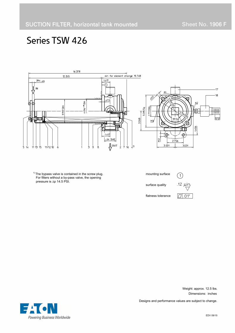
Series TSW 426
SUCTION FILTER, horizontal tank mounted
Sheet No. 1906 F
EDV 09/15
Weight: approx. 12.5 lbs.
Dimensions: inches Designs and performance values are subject to change.
1) The bypass valve is contained in the screw plug. For filters without a by-pass valve, the opening pressure is p 14.5 PSI.
mounting surface surface quality flatness tolerance

Suction Filter
Series TSW 426
Description:
The TSW-filters are directly mounted to the reservoir and connected to the suction-line.
The filter element consists of star-shaped, pleated filter material, which is supported on the inside by a perforated core tube and is bonded to the end caps with a high-quality adhesive. The flow direction is from outside to inside.
Eaton filter elements are known for a high intrinsic stability and an excellent filtration capability, a high dirt-retaining capacity and a long service life.
For filtration finer than 40 μm use the disposable elements made of microglass. Filter elements as fine as 5 μm(c) are available; finer filter elements on request.
Eaton filter elements can be used for petroleum-based fluids, HW emulsions, water glycols, most synthetic fluids and lubrication fluids. Consult factory for specific fluid applications.
When removing the filter cover, a plate-shaped valve closes the suction-inlet of the filter bowl and prevents dirty oil from flowing into the tank. For cleaning, the filter bowl and the filter element can be taken out of the filter head.
1. Type index:
1.1. Complete filter: (ordering example)
TSW. 426. 10VG. -. B. P. -. UG. 7. -. -. O1. E4. -1 2 3 4 5 6 7 8 9 10 11 12 13 14
1 series: TSW = suction filter for horizontal tank-mounting
2 nominal size: 426
3 filter-material and filter-fineness: 80G, 40G, 25G stainless steel wire mesh 25VG, 16VG, 10VG, 6VG, 3VG microglass 10P paper
4 filter element collapse rating: - = not specified
5 filter element design: B = both sides open
6 sealing material: P = Nitrile (NBR) V = Viton (FPM)
7 filter element specification: - = standard VA = stainless steel
8 process connection: UG = thread connection FS = SAE-flange 3000 PSI
9 process connection size: 7 = -24 SAE or 1 ½“ SAE
10 filter housing specification: - = standard
11 internal valve: - = without S = with by-pass valve p 4.1 PSI
12 clogging indicator at M1: - = without O1 = visual, see sheet-no. 1616 E4 = pressure switch, see sheet-no. 1616
13 clogging indicator at M2: possible indicators see position 12 of the type index
14 clogging indicator at M3: possible indicators see position 12 of the type index
1.2. Filter element: (ordering example)
01TS. 425. 10VG. -. B. -. - 1 2 3 4 5 6 7
1 series: 01TS. = suction filter element according to company standard
2 nominal size: 425
3 - 5 / 7 see type index-complete filter
6 seling material: - = without

Technical data:
design temperature: 14 °F to +212 °F operating temperature: 14 °F to +176 °F operating medium mineral oil, other media on request process connection: thread connection or SAE-flange 3000 PSI housing material: Al-casting, glass fiber reinforced polyamide sealing material: Nitrile (NBR) or Viton (FPM), other materials on request installation position: vertical volume tank: .70 Gal.
Classified under the Pressure Equipment Directive 2014/68/EC for mineral oil (fluid group 2), Article 4, Para. 3. Classified under ATEX Directive 2014/34/EC according to specific application (see questionnaire sheet-no. 34279-4).
Pressure drop flow curves:
Filter calculation/sizing
The pressure drop of the assembly at a given flow rate Q is the sum of the housing ∆p and the element ∆p and is calculated as follows:
p assembly = p housing + p element p housing = (see p = f (Q) - characteristics)
p element (PSI) = .
³
For ease of calculation our Filter Selection tool is available online at www.eatonpowersource.com/calculators/filtration/
Material gradient coefficients (MSK) for filter elements
The material gradient coefficients in psi/gpm apply to mineral oil (HLP) with a density of 0.876 kg/dm³ and a kinematic viscosity of 139 SUS (30 mm²/s). The pressure drop changes proportionally to the change in kinematic viscosity and density.
TSW VG G P
3VG 6VG 10VG 16VG 25VG 25G 40G 80G 10P
426 0.887 0.616 0.394 0.343 0.235 0.0226 0.0211 0.0144 0.188
∆p = f(Q) – characteristics according to ISO 3968
The pressure drop characteristics apply to mineral oil (HLP) with a density of 0.876 kg/dm³. The pressure drop changes proportionally to the density.

Symbols:
without indicator
visual O
electric E4
filter without internal valve
filter with internal valve
Spare parts: item qty. designation dimension article-no.
1 1 filter element 01TS.425… 2 1 filter head NG 426 3 1 filter bowl NG 426 4 1 screw plug with by-pass M 120 x 3 1 screw plug without by-pass M 120 x 3
5 1 valve disc 311892 6 1 valve bushing 307548 7 1 O-ring 128 x 3 304602 (NBR) 308140 (FPM) 8 1 O-ring 115 x 3 303963 (NBR) 307762 (FPM) 9 1 O-ring 98 x 4 301914 (NBR) 304765 (FPM)
10 1 O-ring 70 x 4 306253 (NBR) 310280 (FPM) 11 2 O-ring 76 x 4 305599 (NBR) 310291 (FPM) 12 1 sliding ring 307547 13 1 pressure ring 307549 14 1 fillister head cap screw M 6 x 60 307534 15 1 spring 1,6 x 10 x 53 x 12.5 311847 16 1 O-ring 50 x 3 307398 (NBR) 314682 (FPM) 17 1 clogging indicator, visual O1 301722 18 1 clogging indicator, electric E4 311016
Test methods: Filter elements are tested according to the following ISO standards:
ISO 2941 Verification of collapse/burst resistance ISO 2942 Verification of fabrication integrity ISO 2943 Verification of material compatibility with fluids ISO 3723 Method for end load test ISO 3724 Verification of flow fatigue characteristics ISO 3968 Evaluation of pressure drop versus flow characteristics ISO 16889 Multi-pass method for evaluating filtration performance
North America 44 Apple Street Tinton Falls, NJ 07724
Toll Free: 800 656-3344 (North America only)
Tel: +1 732 212-4700 Europe/Africa/Middle East Auf der Heide 2 53947 Nettersheim, Germany
Tel: +49 2486 809-0
Friedensstraße 41 68804 Altlußheim, Germany
Tel: +49 6205 2094-0
An den Nahewiesen 24 55450 Langenlonsheim, Germany
Tel: +49 6704 204-0
China No. 3, Lane 280, Linhong Road Changning District, 200335 Shanghai, P.R. China
Tel: +86 21 5200-0099 Singapore 4 Loyang Lane #04-01/02 Singapore 508914
Tel: +65 6825-1668 Brazil Av. Julia Gaioli, 474 – Bonsucesso 07251-500 – Guarulhos, Brazil
Tel: +55 11 2465-8822
For more information, please email us at [email protected]
or visit www.eaton.com/filtration
© 2015 Eaton. All rights reserved. All trademarks and registered trademarks are the property of their respective owners. All information and recommendations appearing in this brochure concerning the use of products described herein are based on tests believed to be reliable. However, it is the user’s responsibility to determine the suitability for his own use of such products. Since the actual use by others is beyond our control, no guarantee, expressed or implied, is made by Eaton as to the effects of such use or the results to be obtained. Eaton assumes no liability arising out of the use by others of such products. Nor is the information herein to be construed as absolutely complete, since additional information may be necessary or desirable when particular or exceptional conditions or circumstances exist or because of applicable laws or government regulations.

Series TSW 625
SUCTION FILTER, horizontal tank mounted
Sheet No. 1911 E
EDV 09/15
Weight: approx. 12.0 lbs.
Dimensions: inches Designs and performance values are subject to change.
1) The bypass valve is contained in the screw plug. For filters without a by-pass valve, the opening pressure is p 14.5 PSI.
2)
Connect the stand grounding tab to a suitable earth ground point.
mounting surface surface quality flatness tolerance

Suction Filter
Series TSW 625
Description:
The TSW-filters are directly mounted to the reservoir and connected to the suction-line.
The filter element consists of star-shaped, pleated filter material, which is supported on the inside by a perforated core tube and is bonded to the end caps with a high-quality adhesive. The flow direction is from outside to inside.
Eaton filter elements are known for a high intrinsic stability and an excellent filtration capability, a high dirt-retaining capacity and a long service life.
For filtration finer than 40 μm use the disposable elements made of microglass. Filter elements as fine as 5 μm(c) are available; finer filter elements on request.
Eaton filter elements can be used for petroleum-based fluids, HW emulsions, water glycols, most synthetic fluids and lubrication fluids. Consult factory for specific fluid applications.
When removing the filter cover, a plate-shaped valve closes the suction-inlet of the filter bowl and prevents dirty oil from flowing into the tank. For cleaning, the filter bowl and the filter element can be taken out of the filter head.
1. Type index:
1.1. Complete filter: (ordering example)
TSW. 625. 10VG. -. B. P. -. FS. 8. -. -. O1. E4. -1 2 3 4 5 6 7 8 9 10 11 12 13 14
1 series: TSW = suction filter for horizontal tank-mounting
2 nominal size: 625
3 filter-material and filter-fineness: 80G, 40G, 25G stainless steel wire mesh 25VG, 16VG, 10VG, 6VG, 3VG microglass 10P paper
4 filter element collapse rating: - = not specified
5 filter element design: B = both sides open
6 sealing material: P = Nitrile (NBR) V = Viton (FPM)
7 filter element specification: - = standard VA = stainless steel
8 process connection: FS = SAE-flange 3000 PSI
9 process connection size: 8 = 2“
10 filter housing specification: - = standard IS11 = for filter head and filter cover, see sheet-no. 40530
11 internal valve: - = without S = with by-pass valve p 4.1 PSI
12 clogging indicator at M1: - = without O1 = visual, see sheet-no. 1616 E4 = pressure switch, see sheet-no. 1616 PA = potential equalisation
13 clogging indicator at M2: possible indicators see position 12 of the type index
14 clogging indicator at M3: possible indicators see position 12 of the type index
To add an indicator to your filter, use the corresponding indicator data sheet to find the indicator details and add them to the filter assembly model code.
1.2. Filter element: (ordering example)
01TS. 625. 10VG. -. B. -. - 1 2 3 4 5 6 7
1 series: 01TS. = suction filter element according to company standard
2 nominal size: 625
3 - 5 / 7 see type index-complete filter
6 seling material: - = without
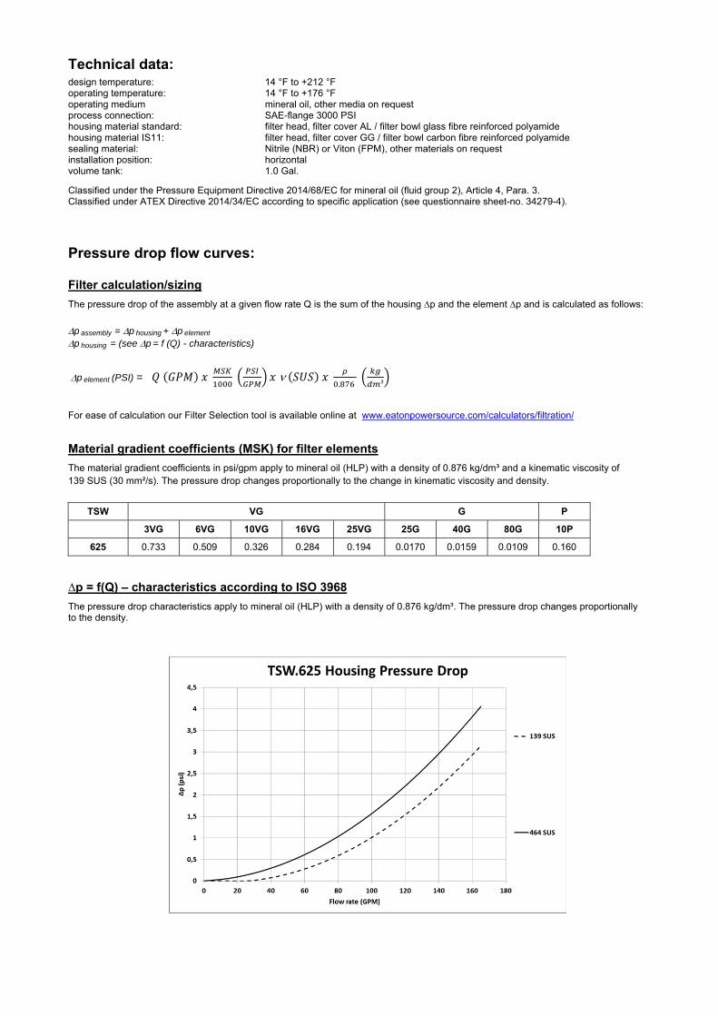
Technical data:
design temperature: 14 °F to +212 °F operating temperature: 14 °F to +176 °F operating medium mineral oil, other media on request process connection: SAE-flange 3000 PSI housing material standard: filter head, filter cover AL / filter bowl glass fibre reinforced polyamide housing material IS11: filter head, filter cover GG / filter bowl carbon fibre reinforced polyamide sealing material: Nitrile (NBR) or Viton (FPM), other materials on request installation position: horizontal volume tank: 1.0 Gal.
Classified under the Pressure Equipment Directive 2014/68/EC for mineral oil (fluid group 2), Article 4, Para. 3. Classified under ATEX Directive 2014/34/EC according to specific application (see questionnaire sheet-no. 34279-4).
Pressure drop flow curves:
Filter calculation/sizing
The pressure drop of the assembly at a given flow rate Q is the sum of the housing ∆p and the element ∆p and is calculated as follows:
p assembly = p housing + p element p housing = (see p = f (Q) - characteristics)
p element (PSI) = .
³
For ease of calculation our Filter Selection tool is available online at www.eatonpowersource.com/calculators/filtration/
Material gradient coefficients (MSK) for filter elements
The material gradient coefficients in psi/gpm apply to mineral oil (HLP) with a density of 0.876 kg/dm³ and a kinematic viscosity of 139 SUS (30 mm²/s). The pressure drop changes proportionally to the change in kinematic viscosity and density.
TSW VG G P
3VG 6VG 10VG 16VG 25VG 25G 40G 80G 10P
625 0.733 0.509 0.326 0.284 0.194 0.0170 0.0159 0.0109 0.160
∆p = f(Q) – characteristics according to ISO 3968
The pressure drop characteristics apply to mineral oil (HLP) with a density of 0.876 kg/dm³. The pressure drop changes proportionally to the density.

Symbols:
without indicator
visual O
electric E4 filter without internal valve
filter with internal valve
Spare parts: item qty. designation dimension article-no.
1 1 filter element 01TS.625… 2 1 filter head NG 625 3 1 filter bowl NG 625 4 1 screw plug with by-pass valve M 140 x 3 1 screw plug without by-pass valve M 140 x 3
5 1 valve disc 318740 6 1 valve bushing 318739 7 1 O-ring 135 x 3,5 318386 (NBR) 318387 (FPM) 8 1 O-ring 140 x 3 304604 (NBR) 307514 (FPM) 9 1 O-ring 120 x 4 305300 (NBR) 307991 (FPM)
10 1 O-ring 76 x 4 305599 (NBR) 310291 (FPM) 11 1 O-ring 104,37 x 3,53 304339 (NBR) 304390 (FPM) 12 1 O-ring 70 x 4 306253 (NBR) 310280 (FPM) 13 1 snap ring B 55 311976 14 1 spring 5,0 x 70 x 117 x 3,5 318742 15 1 disc 318741 16 1 O-ring 56 x 3 307398 (NBR) 314682 (FPM) 17 1 clogging indicator, visual E4 311016 18 1 clogging indicator, electric O1 301722
Test methods: Filter elements are tested according to the following ISO standards:
ISO 2941 Verification of collapse/burst resistance ISO 2942 Verification of fabrication integrity ISO 2943 Verification of material compatibility with fluids ISO 3723 Method for end load test ISO 3724 Verification of flow fatigue characteristics ISO 3968 Evaluation of pressure drop versus flow characteristics ISO 16889 Multi-pass method for evaluating filtration performance
North America 44 Apple Street Tinton Falls, NJ 07724
Toll Free: 800 656-3344 (North America only)
Tel: +1 732 212-4700 Europe/Africa/Middle East Auf der Heide 2 53947 Nettersheim, Germany
Tel: +49 2486 809-0
Friedensstraße 41 68804 Altlußheim, Germany
Tel: +49 6205 2094-0
An den Nahewiesen 24 55450 Langenlonsheim, Germany
Tel: +49 6704 204-0
China No. 3, Lane 280, Linhong Road Changning District, 200335 Shanghai, P.R. China
Tel: +86 21 5200-0099 Singapore 4 Loyang Lane #04-01/02 Singapore 508914
Tel: +65 6825-1668 Brazil Av. Julia Gaioli, 474 – Bonsucesso 07251-500 – Guarulhos, Brazil
Tel: +55 11 2465-8822
For more information, please email us at [email protected]
or visit www.eaton.com/filtration
© 2015 Eaton. All rights reserved. All trademarks and registered trademarks are the property of their respective owners. All information and recommendations appearing in this brochure concerning the use of products described herein are based on tests believed to be reliable. However, it is the user’s responsibility to determine the suitability for his own use of such products. Since the actual use by others is beyond our control, no guarantee, expressed or implied, is made by Eaton as to the effects of such use or the results to be obtained. Eaton assumes no liability arising out of the use by others of such products. Nor is the information herein to be construed as absolutely complete, since additional information may be necessary or desirable when particular or exceptional conditions or circumstances exist or because of applicable laws or government regulations.

Series NF 250
232 PSI
OFFLINE FILTER
Sheet No. 1100 F
EDV 09/15
Weight: approx. 16 lbs.
Dimensions: inches Designs and performance values are subject to change.
M2, p1 = measure connection dirt side M2, p2 = measure connection clean side E1 = air bleeding dirt side E2 = drain dirt side E3 = drain clean side
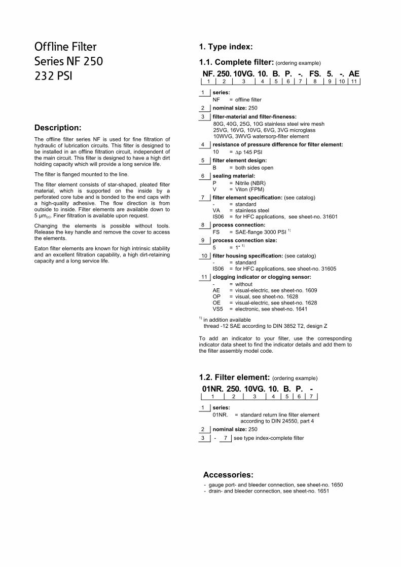
Offline Filter
Series NF 250
232 PSI
Description: The offline filter series NF is used for fine filtration of hydraulic of lubrication circuits. This filter is designed to be installed in an offline filtration circuit, independent of the main circuit. This filter is designed to have a high dirt holding capacity which will provide a long service life.
The filter is flanged mounted to the line.
The filter element consists of star-shaped, pleated filter material, which is supported on the inside by a perforated core tube and is bonded to the end caps with a high-quality adhesive. The flow direction is from outside to inside. Filter elements are available down to 5 µm(c). Finer filtration is available upon request.
Changing the elements is possible without tools. Release the key handle and remove the cover to access the elements.
Eaton filter elements are known for high intrinsic stability and an excellent filtration capability, a high dirt-retaining capacity and a long service life.
1. Type index:
1.1. Complete filter: (ordering example)
NF. 250. 10VG. 10. B. P. -. FS. 5. -. AE1 2 3 4 5 6 7 8 9 10 11
1 series: NF = offline filter
2 nominal size: 250
3 filter-material and filter-fineness: 80G, 40G, 25G, 10G stainless steel wire mesh 25VG, 16VG, 10VG, 6VG, 3VG microglass 10WVG, 3WVG watersorp-filter element
4 resistance of pressure difference for filter element: 10 = p 145 PSI
5 filter element design: B = both sides open
6 sealing material: P = Nitrile (NBR) V = Viton (FPM)
7 filter element specification: (see catalog) - = standard VA = stainless steel IS06 = for HFC applications, see sheet-no. 31601
8 process connection: FS = SAE-flange 3000 PSI 1)
9 process connection size: 5 = 1“ 1)
10 filter housing specification: (see catalog) - = standard IS06 = for HFC applications, see sheet-no. 31605
11 clogging indicator or clogging sensor: - = without AE = visual-electric, see sheet-no. 1609 OP = visual, see sheet-no. 1628 OE = visual-electric, see sheet-no. 1628 VS5 = electronic, see sheet-no. 1641
1) in addition available thread -12 SAE according to DIN 3852 T2, design Z To add an indicator to your filter, use the corresponding indicator data sheet to find the indicator details and add them to the filter assembly model code.
1.2. Filter element: (ordering example)
01NR. 250. 10VG. 10. B. P. - 1 2 3 4 5 6 7
1 series: 01NR. = standard return line filter element
according to DIN 24550, part 4
2 nominal size: 250
3 - 7 see type index-complete filter
Accessories:
- gauge port- and bleeder connection, see sheet-no. 1650 - drain- and bleeder connection, see sheet-no. 1651

Technical data:
design temperature: 14 °F to +212 °F operating temperature: 14 °F to +176 °F operating medium mineral oil, other media on request max. operating pressure: 232 PSI test pressure: 333 PSI process connection: SAE-flange 3000 PSI housing material: aluminium forging alloy sealing material: Nitrile (NBR) or Viton (FPM), other materials on request installation position: vertical measure connections: BSPP 1/8 drain- and bleeder connections: BSPP 1/4 volume tank: .87 Gal.
Classified under the Pressure Equipment Directive 2014/68/EC for mineral oil (fluid group 2), Article 4, Para. 3. Classified under ATEX Directive 2014/34/EC according to specific application (see questionnaire sheet-no. 34279-4).
Pressure drop flow curves:
Filter calculation/sizing
The pressure drop of the assembly at a given flow rate Q is the sum of the housing ∆p and the element ∆p and is calculated as follows:
p assembly = p housing + p element p housing = (see p = f (Q) - characteristics)
p element (PSI) = .
³
For ease of calculation our Filter Selection tool is available online at www.eatonpowersource.com/calculators/filtration/
Material gradient coefficients (MSK) for filter elements
The material gradient coefficients in psi/gpm apply to mineral oil (HLP) with a density of 0.876 kg/dm³ and a kinematic viscosity of 139 SUS (30 mm²/s). The pressure drop changes proportionally to the change in kinematic viscosity and density.
NF VG
3VG 6VG 10VG 16VG 25VG
250 0.669 0.464 0.297 0.259 0.177
∆p = f(Q) – characteristics according to ISO 3968
The pressure drop characteristics apply to mineral oil (HLP) with a density of 0.876 kg/dm³. The pressure drop changes proportionally to the density.

Symbols: without indicator with electric
indicator AE 30 and AE 40
with visual-electric indicator
AE 50 and AE 62
with visual-electric indicator
AE 70 and AE 80
with visual indicator
OP
with visual-electric indicator
OE
with electronic clogging sensor
VS5
Spare parts: item qty. designation dimension article-no.
1 1 filter element 01NR.250… 2 1 filter cover 30615-3 315437 3 1 mini-measuring connection MA.1.ST 305453 4 2 screw plug ¼ BSPP 305003 5 1 straining screw 30631-3 316404 6 1 O-ring 110 x 6 337001 (NBR) 337002 (FPM) 7 2 O-ring 52 x 3 314206 (NBR) 316698 (FPM) 8 1 O-ring 18 x 3 304359 (NBR) 304399 (FPM) 9 1 clogging indicator, visual OP see sheet-no. 1628
10 1 clogging indicator, visual-electric OE see sheet-no. 1628 11 1 clogging indicator, visual-electric AE see sheet-no. 1609 12 1 clogging sensor, electronic VS5 see sheet-no. 1641 13 2 O-ring 14 x 2 304342 (NBR) 304722 (FPM) 14 2 screw plug 1/8 BSPP 304791 15 1 screw plug 1/8 BSPP 305496 16 1 O-ring 123 x 4 337003 (NBR) 337004 (FPM)
item 14 execution only without clogging indicator or clogging sensor
Test methods: Filter elements are tested according to the following ISO standards:
ISO 2941 Verification of collapse/burst resistance ISO 2942 Verification of fabrication integrity ISO 2943 Verification of material compatibility with fluids ISO 3723 Method for end load test ISO 3724 Verification of flow fatigue characteristics ISO 3968 Evaluation of pressure drop versus flow characteristics ISO 16889 Multi-pass method for evaluating filtration performance
North America 44 Apple Street Tinton Falls, NJ 07724
Toll Free: 800 656-3344 (North America only)
Tel: +1 732 212-4700 Europe/Africa/Middle East Auf der Heide 2 53947 Nettersheim, Germany
Tel: +49 2486 809-0
Friedensstraße 41 68804 Altlußheim, Germany
Tel: +49 6205 2094-0
An den Nahewiesen 24 55450 Langenlonsheim, Germany
Tel: +49 6704 204-0
China No. 3, Lane 280, Linhong Road Changning District, 200335 Shanghai, P.R. China
Tel: +86 21 5200-0099 Singapore 4 Loyang Lane #04-01/02 Singapore 508914
Tel: +65 6825-1668 Brazil Av. Julia Gaioli, 474 – Bonsucesso 07251-500 – Guarulhos, Brazil
Tel: +55 11 2465-8822
For more information, please email us at [email protected]
or visit www.eaton.com/filtration
© 2015 Eaton. All rights reserved. All trademarks and registered trademarks are the property of their respective owners. All information and recommendations appearing in this brochure concerning the use of products described herein are based on tests believed to be reliable. However, it is the user’s responsibility to determine the suitability for his own use of such products. Since the actual use by others is beyond our control, no guarantee, expressed or implied, is made by Eaton as to the effects of such use or the results to be obtained. Eaton assumes no liability arising out of the use by others of such products. Nor is the information herein to be construed as absolutely complete, since additional information may be necessary or desirable when particular or exceptional conditions or circumstances exist or because of applicable laws or government regulations.

Series NF 631
232 PSI
OFFLINE FILTER
Sheet No. 1115 L
EDV 09/15
Weight: approx. 37 lbs.
Dimensions: inches Designs and performance values are subject to change.
M2, p1 = measure connection dirt side M2, p2 = measure connection clean side E1 = air bleeding dirt side E2 = drain dirt side E3 = drain clean side

Offline Filter
Series NF 631
232 PSI
Description: The offline filter series NF is used for fine filtration of hydraulic of lubrication circuits. This filter is designed to be installed in an offline filtration circuit, independent of the main circuit. This filter is designed to have a high dirt holding capacity which will provide a long service life.
The filter is flanged mounted to the line.
The filter element consists of star-shaped, pleated filter material, which is supported on the inside by a perforated core tube and is bonded to the end caps with a high-quality adhesive. The flow direction is from outside to inside. Filter elements are available down to 5 µm(c). Finer filtration is available upon request.
Changing the elements is possible without tools. Release the key handle and remove the cover to access the elements.
Eaton filter elements are known for high intrinsic stability and an excellent filtration capability, a high dirt-retaining capacity and a long service life.
1. Type index:
1.1. Complete filter: (ordering example)
NF. 631. 10VG. 10. B. P. -. FS. 6. -. AE1 2 3 4 5 6 7 8 9 10 11
1 series: NF = offline filter
2 nominal size: 631
3 filter-material and filter-fineness: 80G, 40G, 25G, 10G stainless steel wire mesh 25VG, 16VG, 10VG, 6VG, 3VG microglass 10WVG, 3WVG watersorp-filter element
4 filter element collapse rating: 10 = p 145 PSI
5 filter element design: B = both sides open
6 sealing material: P = Nitrile (NBR) V = Viton (FPM)
7 filter element specification: (see catalog) - = standard VA = stainless steel IS06 = for HFC applications, see sheet-no. 31601
8 process connection: FS = SAE-flange 3000 PSI 1)
9 process connection size: 6 = 1 ¼“ 1)
10 filter housing specification: (see catalog) - = standard IS06 = for HFC applications, see sheet-no. 31605
11 clogging indicator or clogging sensor: - = without AE = visual-electric, see sheet-no. 1609 OP = visual, see sheet-no. 1628 OE = visual-electric, see sheet-no. 1628 VS5 = electronic, see sheet-no. 1641
1) in addition available thread -16 SAE according to DIN 3852 T2, design Z To add an indicator to your filter, use the corresponding indicator data sheet to find the indicator details and add them to the filter assembly model code.
1.2. Filter element: (ordering example)
01NR. 630. 10VG. 10. B. P. - 1 2 3 4 5 6 7
1 series: 01NR. = standard return line filter element
according to DIN 24550, part 4
2 nominal size: 630
3 - 7 see type index-complete filter
Accessories:
- gauge port- and bleeder connection, see sheet-no. 1650 - drain- and bleeder connection, see sheet-no. 1651 - SAE-counter flange, see sheet no. 1652
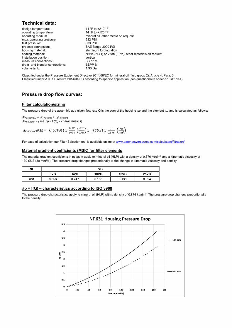
Technical data:
design temperature: 14 °F to +212 °F operating temperature: 14 °F to +176 °F operating medium mineral oil, other media on request max. operating pressure: 232 PSI test pressure: 333 PSI process connection: SAE-flange 3000 PSI housing material: aluminum forging alloy sealing material: Nitrile (NBR) or Viton (FPM), other materials on request installation position: vertical measure connections: BSPP ¼ drain- and bleeder connections: BSPP ½ volume tank: 1.90 Gal.
Classified under the Pressure Equipment Directive 2014/68/EC for mineral oil (fluid group 2), Article 4, Para. 3. Classified under ATEX Directive 2014/34/EC according to specific application (see questionnaire sheet-no. 34279-4).
Pressure drop flow curves:
Filter calculation/sizing
The pressure drop of the assembly at a given flow rate Q is the sum of the housing ∆p and the element ∆p and is calculated as follows:
p assembly = p housing + p element p housing = (see p = f (Q) - characteristics)
p element (PSI) = .
³
For ease of calculation our Filter Selection tool is available online at www.eatonpowersource.com/calculators/filtration/
Material gradient coefficients (MSK) for filter elements
The material gradient coefficients in psi/gpm apply to mineral oil (HLP) with a density of 0.876 kg/dm³ and a kinematic viscosity of 139 SUS (30 mm²/s). The pressure drop changes proportionally to the change in kinematic viscosity and density.
NF VG
3VG 6VG 10VG 16VG 25VG
631 0.356 0.247 0.158 0.138 0.094
∆p = f(Q) – characteristics according to ISO 3968
The pressure drop characteristics apply to mineral oil (HLP) with a density of 0.876 kg/dm³. The pressure drop changes proportionally to the density.

Symbols: without indicator with electric
indicator AE 30 and AE 40
with visual-electric indicator
AE 50 and AE 62
with visual-electric indicator
AE 70 and AE 80
with visual indicator
OP
with visual-electric indicator
OE
with electronic clogging sensor
VS5
Spare parts: item qty. designation dimension article-no.
1 1 filter element 01NR.630… 2 1 filter cover 30600-3 315492 3 1 mini-measuring connection MA.1.St 305453 4 2 screw plug ½ BSPP 304678 5 1 straining screw 30595-3 316312 6 1 O-ring 140 x 6 315392 (NBR) 316322 (FPM) 7 2 O-ring 70 x 4 306253 (NBR) 310280 (FPM) 8 1 O-ring 22 x 3 304387 (NBR) 304931 (FPM) 9 1 clogging indicator, visual OP see sheet-no. 1628
10 1 clogging indicator, visual-electric OE see sheet-no. 1628 11 1 clogging indicator, visual-electric AE see sheet-no. 1609 12 1 clogging sensor, electronic VS5 see sheet-no. 1641 13 2 O-ring 14 x 2 304342 (NBR) 304722 (FPM) 14 2 screw plug 1/8 BSPP 304791 15 1 screw plug 1/8 BSPP 305496 16 1 O-ring 153 x 4 320763 (NBR) 322368 (FPM)
item 14 execution only without clogging indicator or clogging sensor
Test methods: Filter elements are tested according to the following ISO standards:
ISO 2941 Verification of collapse/burst resistance ISO 2942 Verification of fabrication integrity ISO 2943 Verification of material compatibility with fluids ISO 3723 Method for end load test ISO 3724 Verification of flow fatigue characteristics ISO 3968 Evaluation of pressure drop versus flow characteristics ISO 16889 Multi-pass method for evaluating filtration performance
North America 44 Apple Street Tinton Falls, NJ 07724
Toll Free: 800 656-3344 (North America only)
Tel: +1 732 212-4700 Europe/Africa/Middle East Auf der Heide 2 53947 Nettersheim, Germany
Tel: +49 2486 809-0
Friedensstraße 41 68804 Altlußheim, Germany
Tel: +49 6205 2094-0
An den Nahewiesen 24 55450 Langenlonsheim, Germany
Tel: +49 6704 204-0
China No. 3, Lane 280, Linhong Road Changning District, 200335 Shanghai, P.R. China
Tel: +86 21 5200-0099 Singapore 4 Loyang Lane #04-01/02 Singapore 508914
Tel: +65 6825-1668 Brazil Av. Julia Gaioli, 474 – Bonsucesso 07251-500 – Guarulhos, Brazil
Tel: +55 11 2465-8822
For more information, please email us at [email protected]
or visit www.eaton.com/filtration
© 2015 Eaton. All rights reserved. All trademarks and registered trademarks are the property of their respective owners. All information and recommendations appearing in this brochure concerning the use of products described herein are based on tests believed to be reliable. However, it is the user’s responsibility to determine the suitability for his own use of such products. Since the actual use by others is beyond our control, no guarantee, expressed or implied, is made by Eaton as to the effects of such use or the results to be obtained. Eaton assumes no liability arising out of the use by others of such products. Nor is the information herein to be construed as absolutely complete, since additional information may be necessary or desirable when particular or exceptional conditions or circumstances exist or because of applicable laws or government regulations.
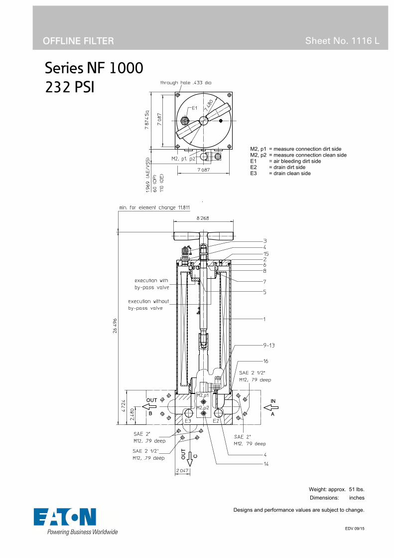
Series NF 1000
232 PSI
OFFLINE FILTER
Sheet No. 1116 L
EDV 09/15
Weight: approx. 51 lbs.
Dimensions: inches Designs and performance values are subject to change.
M2, p1 = measure connection dirt side M2, p2 = measure connection clean side E1 = air bleeding dirt side E2 = drain dirt side E3 = drain clean side

Offline Filter
Series NF 1000
232 PSI
Description: The offline filter series NF is used for fine filtration of hydraulic of lubrication circuits. This filter is designed to be installed in an offline filtration circuit, independent of the main circuit. This filter is designed to have a high dirt holding capacity which will provide a long service life.
The filter is flanged mounted to the line.
The filter element consists of star-shaped, pleated filter material, which is supported on the inside by a perforated core tube and is bonded to the end caps with a high-quality adhesive. The flow direction is from outside to inside. Filter elements are available down to 5 µm(c). Finer filtration is available upon request.
Changing the elements is possible without tools. Release the key handle and remove the cover to access the elements.
Eaton filter elements are known for high intrinsic stability and an excellent filtration capability, a high dirt-retaining capacity and a long service life.
1. Type index:
1.1. Complete filter: (ordering example)
NF. 1000. 10VG. 10. B. P. -. FS. 3. -. -. AE1 2 3 4 5 6 7 8 9 10 11 12
1 series: NF = offline filter
2 nominal size: 1000
3 filter-material and filter-fineness: 80G, 40G, 25G, 10G stainless steel wire mesh 25VG, 16VG, 10VG, 6VG, 3VG microglass 10WVG, 3WVG watersorp-filter element 4 filter element collapse rating: 10 = p 145 PSI
5 filter element design: B = both sides open
6 sealing material: P = Nitrile (NBR) V = Viton (FPM)
7 filter element specification: (see catalog) - = standard VA = stainless steel IS06 = for HFC applications, see sheet-no. 31601
8 connection: FS = SAE-flange 3000 PSI
9 no. of version:
connection version A B C
connection size connection size connection size1 8 8 - 2 8 8 8 3 9 9 - 4 9 9 9
connection size: 8 = 2“ 9 = 2 ½“ - = without connection
10 filter housing specification: (see catalog) - = standard IS06 = for HFC applications, see sheet-no. 31605
11 internal valve: - = without S1 = with by-pass valve p 51 PSI
12 clogging indicator or clogging sensor : - = without AE = visual-electrical, see sheet-no. 1609 OP = visual, see sheet-no. 1628 OE = visual-electrical, see sheet-no. 1628 VS5 = electrical, see sheet-no. 1641
To add an indicator to your filter, use the corresponding indicator data sheet to find the indicator details and add them to the filter assembly model code.
1.2. Filter element: (ordering example)
01NR. 1000. 10VG. 10. B. P. - 1 2 3 4 5 6 7
1 series: 01NR. = standard return line filter element
according to DIN 24550, T4
2 nominal size: 1000
3 - 7 see type index-complete filter
Accessories:
- gauge port- and bleeder connection, see sheet-no. 1650 - drain- and bleeder-connections, see sheet-no. 1651 - counter flange, see sheet-no. 1652

Technical data:
design temperature: 14 °F to +212 °F operating temperature: 14 °F to +176 °F operating medium mineral oil, other media on request max. operating pressure: 232 PSI test pressure: 333 PSI process connection: SAE-flange 3000 PSI housing material: aluminium forging alloy sealing material: Nitrile (NBR) or Viton (FPM), other materials on request installation position: vertical measure connections: BSPP ¼ drain- and bleeder connections: BSPP ½ volume tank: 3.0 Gal.
Classified under the Pressure Equipment Directive 2014/68/EC for mineral oil (fluid group 2), Article 4, Para. 3. Classified under ATEX Directive 2014/34/EC according to specific application (see questionnaire sheet-no. 34279-4).
Pressure drop flow curves:
Filter calculation/sizing
The pressure drop of the assembly at a given flow rate Q is the sum of the housing ∆p and the element ∆p and is calculated as follows:
p assembly = p housing + p element p housing = (see p = f (Q) - characteristics)
p element (PSI) = .
³
For ease of calculation our Filter Selection tool is available online at www.eatonpowersource.com/calculators/filtration/
Material gradient coefficients (MSK) for filter elements
The material gradient coefficients in psi/gpm apply to mineral oil (HLP) with a density of 0.876 kg/dm³ and a kinematic viscosity of 139 SUS (30 mm²/s). The pressure drop changes proportionally to the change in kinematic viscosity and density.
NF VG
3VG 6VG 10VG 16VG 25VG
1000 0.237 0.165 0.105 0.092 0.063
∆p = f(Q) – characteristics according to ISO 3968
The pressure drop characteristics apply to mineral oil (HLP) with a density of 0.876 kg/dm³. The pressure drop changes proportionally to the density.

Symbols: without indicator with electric
indicator AE 30 and AE 40
with visual-electric indicator
AE 50 and AE 62
with visual-electric indicator
AE 70 and AE 80
with visual indicator
AOR/AOC/OP
with visual-electric indicator
OE
with electronic clogging sensor
VS5 filter without internal valve
filter with by-pass valve
Spare parts: item qty. designation dimension article-no.
1 1 filter element 01NR.1000… 2 1 filter cover without by-pass valve 31065-3 1 filter cover with by-pass valve S1 31461-3
3 1 mini-measuring connection MA.3.ST 308630 4 3 screw plug ½ BSPP 304678 5 1 O-ring (only with by-pass valve) 22 x 3 304387 (NBR) 304931 (FPM) 6 1 O-ring 170 x 6 304799 (NBR) 306529 (FPM) 7 2 O-ring 90 x 4 306941(NBR) 307031(FPM) 8 1 O-ring 22 x 3 304387(NBR) 304931(FPM) 9 1 clogging indicator, visual OP see sheet-no. 1628
10 1 clogging indicator, visual-electric OE see sheet-no. 1628 11 1 clogging indicator, visual-electric AE see sheet-no. 1609 12 1 clogging sensor, electronic VS5 see sheet-no. 1641 13 2 O-ring 14 x 2 304342 (NBR) 304722 (FPM) 14 2 screw plug 1/8 BSPP 304791 15 1 screw plug 1/8 BSPP 305496 16 1 O-ring 183 x 4 3337005(NBR) 337006(FPM)
item 14 execution only without clogging indicator or clogging sensor
Test methods: Filter elements are tested according to the following ISO standards:
ISO 2941 Verification of collapse/burst resistance ISO 2942 Verification of fabrication integrity ISO 2943 Verification of material compatibility with fluids ISO 3723 Method for end load test ISO 3724 Verification of flow fatigue characteristics ISO 3968 Evaluation of pressure drop versus flow characteristics ISO 16889 Multi-pass method for evaluating filtration performance
North America 44 Apple Street Tinton Falls, NJ 07724
Toll Free: 800 656-3344 (North America only)
Tel: +1 732 212-4700 Europe/Africa/Middle East Auf der Heide 2 53947 Nettersheim, Germany
Tel: +49 2486 809-0
Friedensstraße 41 68804 Altlußheim, Germany
Tel: +49 6205 2094-0
An den Nahewiesen 24 55450 Langenlonsheim, Germany
Tel: +49 6704 204-0
China No. 3, Lane 280, Linhong Road Changning District, 200335 Shanghai, P.R. China
Tel: +86 21 5200-0099 Singapore 4 Loyang Lane #04-01/02 Singapore 508914
Tel: +65 6825-1668 Brazil Av. Julia Gaioli, 474 – Bonsucesso 07251-500 – Guarulhos, Brazil
Tel: +55 11 2465-8822
For more information, please email us at [email protected]
or visit www.eaton.com/filtration
© 2015 Eaton. All rights reserved. All trademarks and registered trademarks are the property of their respective owners. All information and recommendations appearing in this brochure concerning the use of products described herein are based on tests believed to be reliable. However, it is the user’s responsibility to determine the suitability for his own use of such products. Since the actual use by others is beyond our control, no guarantee, expressed or implied, is made by Eaton as to the effects of such use or the results to be obtained. Eaton assumes no liability arising out of the use by others of such products. Nor is the information herein to be construed as absolutely complete, since additional information may be necessary or desirable when particular or exceptional conditions or circumstances exist or because of applicable laws or government regulations.
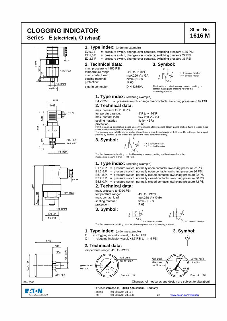
1. Type index: (ordering example)
E2.0,3.P = pressure switch, change over contacts, switching pressure 4.35 PSI E2.1,5.P = pressure switch, change over contacts, switching pressure 22 PSIE2.2,5.P = pressure switch, change over contacts, switching pressure 36 PSI
2. Technical data: 3. Symbol:
max. pressure to 1450 PSI temperature range: max. contact load: sealing material: protection:
-4°F to +176°F max.250 V /5A nitrile (NBR) IP 65
1 + 2 contact breaker 1 + 4 contact maker
plug-in connector: DIN 43650A The functions contact making, contact breaking or contact making and breaking refer to the increasing pressure.
1. Type index: (ordering example)
E4.-0,25.P = pressure switch, change over contacts, switching pressure -3.62 PSI 2. Technical data:
max. pressure to 1160 PSI temperature range: -4°F to +176°F max. contact load: max.250 V /5A sealing material: nitrile (NBR) protection: IP 65 For the electrical connection please use only enclosed utensil socket. Other utensil sockets have a longer fixing screw which can destroy the inside micro switch. The screw of an available utensil socket should have a max. thread reach of 1.10 inch. Do not forget the shaped packing by sticking up the utensil and tighten the fixing screw moderately.
3. Symbol: 1 + 2 contact maker 1 + 3 contact breaker
The functions contact making, contact breaking or contact making and breaking refer to the increasing pressure (0 PSI -.01 PSI) .
1. Type index: (ordering example)
E1.1,5.P = pressure switch, normally open contacts, switching pressure 22 PSI E1.2,5.P = pressure switch, normally open contacts, switching pressure 36 PSI E5.1,5.P = pressure switch, normally closed contacts, switching pressure 22 PSI E5.2,5.P = pressure switch, normally closed contacts, switching pressure 36 PSI E5.5,0.P = pressure switch, normally closed contacts, switching pressure 72 PSI 2. Technical data:
max. pressure to 4350 PSI temperature range: -4°F to +212°F max. contact load: max.250 V /0,5A sealing material: nitrile (NBR) protection: IP 65
3. Symbol:
1 + 2 contact maker 1 + 2 contact breaker
The function contact making or contact breaking refer to the increasing pressure.
1. Type index: (ordering example) 3. Symbol: O O1
==
clogging indicator visual, 0 to 145 PSI clogging indicator visual, +8.7 PSI to -14.5 PSI
CLOGGING INDICATOR Series E (electrical), O (visual)
Sheet No. 1616 M
Changes of measures and design are subject to alteration!
EDV 03/15
2. Technical data:
temperature range: -4°F to +212°F
+49 (0)6205 2094-0 +49 (0)6205 2094-40
phone fax
Friedensstrasse 41, 68804 Altlussheim, Germany url
www.eaton.com/filtration

CLOGGING INDICATOR Series AOR, AOC (thread execution)
Sheet No. 1606 D
1. Clogging indicator AOR, AOC
1.1. Type index: (ordering example)
AOR. 1,5. P. - 1 2 3 4
1 series: AOR = clogging indicator, visual with reset function AOC = clogging indicator, visual with control function 2 indicator-pressure difference: p-nominal 1,5 = 22 PSI 2,5 = 36 PSI 5,0 = 73 PSI 3 sealing material: P = Nitrile (NBR) V = Viton (FPM) 4 material: - = Standard (aluminium) VA = stainless steel
2. Technical data:
temperature ranges - operating temperature: + 14°F to +176° F
(for a short time +212°F) - resistant to compression: -22°F to +212°F - survival temperature: -40°F to +212°F max. operating pressure: 6000 PSI (stainless steel)
3200 PSI (aluminium) max. pressure difference: 2320 PSI reset condition: < 60% p-nominal control condition: < 80% p-nominal max. display error: ± 10% fatigue strength: max. 1 Mio load cycles for aluminium
3. Spare parts:
item qty. designation dimension article-no. 1 1 O-ring 15 x 1,5 315357 (NBR)
315427 (FPM) 2 1 O-ring 22 x 2 304708 (NBR)
304721 (FPM) 3 1 cap 315325 (PUR)
4. Symbol:
p1 = measure connection supply p2 = measure connection output
Changes of measures and design are subject to alteration!
EDV 02/15
+49 (0)6205 2094-0 +49 (0)6205 2094-40
phone fax
Friedensstrasse 41, 68804 Altlussheim, Germany url
www.eaton.com/filtration

5. Description:
The clogging indicators with designation AOR and AOC are visual pressure difference indicators with a reset function or control function. These pressure difference indicators can be built on to all pressure filters where (p≤ 6000 PSI stainless steel, p≤ 3200 PSI aluminium) , and for which a corresponding allocation is provided on the respective dimension sheet. As the filter element becomes increasingly clogged, the difference between the inflow pressure p1 and the outflow pressure p2 of the filter will become larger. The display function is triggered at the switching pressure difference: this depends on the pressure difference just mentioned, and is independent of the operating pressure. A measuring piston which is subject to the inflow and outflow pressure moves against a measuring spring in a manner which depends on the pressure difference. The tractive force between two magnets in the measuring piston and in the display cylinder changes according to the distance moved. At the switching point, the tractive force between the magnets and the force of the spring on the display cylinder are equally large, and are opposed. In the range ± 10% of the set switching pressure, the spring on the display cylinder causes the display cylinder to move suddenly into the „filter element clogged“ display position. This means that the colour in the display field changes from green to red. In the case of the clogging indicator AOR the display position „filter element clogged“ is fixed, and continues to be maintained even if the pressure difference returns to permissible values, dependent on the viscosity or the rate of flow. The fixed „element clogged“ display position can be canceled by operating the reset button, provided that the reset condition is satisfied. In the case of the clogging indicator AOC the display position „filter element clogged“ is only fixed in the pressure difference range 30 10% of the switching pressure difference. In the range < 30 10% of the switching pressure difference occurs a self-instructed shift down to the display position „permissible range“. In the range > 30%,< 80% of the switching pressure difference, the display position „filter element clogged“ can be restored for control functions with the control button. The reset- or control button is located in a position where it is protected from dirt, underneath the elastic cap, item 3, and should be operated with slight manual pressure < 10N. Note on functional behaviour: The „filter element clogged“ display will also be triggered if the pressure difference exceeds the switching pressure difference for only a brief period (> 100ms). The „filter element clogged“ display is triggered in the event of oscillatory or impulse excitations > 1g at values < 90% of the switching pressure difference.
6. Operating instructions:
Normally filters are supplied with mounted clogging indicator. When retrofitting - the filter is to be discharged of the operating pressure. - dismantling the screw plug out of the bare hole which is foreseen for the clogging indicator - screw in the clogging indicator into the bare hole (starting torque 74 lb.-ft. stainless steel, starting torque 59 lb.-ft. aluminium) It is necessary to make sure the availability and the right positioning of sealing parts - O-ring 22 x 2 and - O-ring 15 x 1,5 as well as a dirt-free mounting.
7. Maintenance:
This device is maintenance-free; however, care should be taken to ensure that no cleaning agent or solvents reach the transparent hood and the elastic cap over the reset button or control button.
US 1606 D

CLOGGING INDICATOR Series AE (electrical / visual-electrical, block execution)
Sheet No. 1609 I
1. Clogging indicator AE
1.1. Type index: (ordering example)
AE. 30. 1,5. P. -. B. - 1 2 3 4 5 6 7
1 series: AE = clogging indicator, electrical /
visual-electrical 2 version: 30-80 = see table below 3 indicator-pressure difference: p-nominal 1,5 = 22 PSI 2,5 = 36 PSI 5,0 = 73 PSI 4 sealing material: P = Nitrile (NBR) V = Viton (FPM) 5 material: (block) - = standard VA = stainless steel 6 execution: B = block execution 7 damper: - = standard with hydraulic damper 1 = without hydraulic damper
2. Technical data:
temperature ranges - operating temperature: + 14°F to +176° F
(for a short time +212°F) - resistant to compression: -22°F to +212°F - survival temperature: -40°F to +212°F max. operating pressure: 6000 PSI max. pressure difference: 2320 PSI
version luminous indication
contact voltage max. rupturing capacity (resistive load)
max. switching current (resistive load)
connection protection
30 - ...... 175V DC 3 VA 0,25 A ...... 125V AC 3 Watt 0,25 A
40 - contact maker ...... 175V DC 20 VA 1,0 A line adapter according to and contact breaker ...... 230V AC 10 Watt 0,5 A DIN 43650-designA/ISO4400
50 1x LED 1) 120V AC/DC 3 Watt/VA 0,025 A with 120V AC/DC
62 1x LED 110....230V AC/DC 20 Watt/VA 0,180 A with 110V AC/DC IP 65 according to 0,090 A with 230V AC/DC DIN EN 60529
70 2x LED 24V DC 3 VA 0,080 A with 24V DC 80 2x LED 24V DC 20 VA 0,750 A with 24V DC
1) LED = light emitting diode
Changes of measures and design are subject to alteration! EDV 08/12
+49 (0)6205 2094-0 +49 (0)6205 2094-40
phone fax
Friedensstrasse 41, 68804 Altlussheim, Germany url
www.eaton.com/filtration

3. Spare parts:
item qty. designation dimension article-no. type 1 2 O-ring 14 x 2 304342 (NBR) versions 30 - 80 304722 (FPM)
2 1 line adapter 312492 versions 30 and 40 1 line adapter
with LED 24V 315012 versions 70 and 80
1 line adapter with LED 120V
DIN 43650-designA/ISO4400 315010 version 50
1 line adapter with LED 110...230V
332235 version 62
4. Symbols:
hydraulic-electrical symbol connection configuration for LED
versions versions versions version version versions 30 and 40 50 and 62 70 and 80 50 62 70 and 80
p1 = measure connection supply p2 = measure connection output
5. Description:
The AE 30 and AE 40 pollution indicators are electrical differential pressure indicators. The AE 50 to AE 80 pollution indicators are combined optical and electrical differential pressure indicators. These differential pressure indicators can be fitted to all pressure filters p 6000 PSI for which there is a corresponding assignment on the relevant dimension drawing. As the degree of pollution of the filter element rises, so the difference between the entry pressure p1 and the exit pressure p2 of the filter increases. Depending on this pressure difference and irrespective of the operating pressure, in the pollution indicators - AE 30 and AE 40, two electrical signals (contact maker/contact breaker) are triggered - AE 50 and AE 62, two electrical signals (contact maker/contact breaker) are triggered and one optical signal is formed - AE 70 and AE 80, two electrical signals (contact maker/contact breaker) are triggered and two optical signals are formed. A metering piston subjected to the entry and exit pressure moves against a metering spring according to the pressure differential. Depending on the path, a permanent magnet integrated in the metering piston activates a reed contact (electromagnetic switch) and triggers the electrical signal. The electrical and optical indication is effected as a digital signal at the given switching pressure. Versions 50 to 80 of the pollution indicator are fitted with additional LED displays. The optical LED signal becomes visible according to the selected version in the translucent cover plate of the line box on the pollution indicator. In the pollution indicators - AE 50 and AE 62, the red LED signals that the filter element needs to be changed - AE 70 and AE 80, the green LED signals the normal operating state ( filter element not yet polluted to an unacceptable level), while the red LED signals that the filter element needs to be changed.
6. Operating instructions:
Normally filters are supplied with mounted clogging indicators. It is necessary to make sure the availability and the right positioning of sealing parts O-ring 14 x 2 as well as a dirt-free mounting. The electrical contacts are to be connected according to the graphical symbol shown on the type plate of the clogging indicator.
7. Maintenance:
The device is maintenance-free, however, note that no cleaning fluids and solvents get on the transparent cap of the optical indicator.
US 1609 I

CLOGGING INDICATOR Series AE (electrical / visual-electrical, thread execution)
1. Clogging indicator AE
1.1. Type index: (ordering example)
AE. 30. 1,5. P. -. -. - 1 2 3 4 5 6 7
1 series:
AE = clogging indicator, electrical / visual-electrical
2 version:
30-80 = see table below 3 indicator-pressure difference: ∆p-nominal
1,5 = 22 PSI 2,5 = 36 PSI 5,0 = 73 PSI 4 sealing material:
P = Nitrile (NBR) V = Viton (FPM) 5 material:
- = standard (aluminium) VA = stainless steel 6 execution:
- = standard 7 damper:
- = standard with hydraulic damper 1 = without hydraulic damper
2. Technical data:
temperature ranges - operating temperature: + 14°F to +176° F
(for a short time +212°F) - resistant to compression: -22°F to +212°F - survival temperature: -40°F to +212°F max. operating pressure: 6000 PSI (stainless steel)
3200 PSI (aluminium) max. pressure difference: 2320 PSI fatigue strength: max. 1 Mio load cycles
Clogging indicator AE with redundant switches, see data sheet-no. 40968-4
Changes of measures and design are subject to alteration!
Sheet No.
1615 L
version luminous indication
contact voltage max. rupturing capacity (resistive load)
max. switching current (resistive load)
connection protection
30 - ...... 175V DC 3 VA 0,25 A ...... 125V AC 3 Watt 0,25 A line adapter according to
40 - contact maker ...... 175V DC 20 VA 1,0 A DIN 43650-designA/ISO4400 and contact breaker ...... 230V AC 10 Watt 0,5 A
50 1x LED 1) 120V AC/DC 3 Watt/VA 0,025 A with 120V AC/DC
IP 65 accordingt to
62 1x LED 110....230V AC/DC 20 Watt/VA 0,180 A with 110V AC/DC DIN EN 60529 0,090 A with 230V AC/DC
70 2x LED 24V DC 3 VA 0,080 A with 24V DC
80 2x LED 24V DC 20 VA 0,750 A with 24V DC
1) LED = light emitting diode
EDV 12/14
+49 (0)6205 2094-0 +49 (0)6205 2094-40
phone
fax
Friedensstrasse 41, 68804 Altlussheim, Germany
url
www.eaton.com/filtration

3. Spare parts:
item qty. designation dimension article-no. type
1 1 O-ring 14 x 2 304342 (NBR)
304722 (FPM) versions 30 - 80
2 1 O-ring 22 x 2 304708 (NBR)
304721 (FPM)
3 1 line adapter 312492 versions 30 and 40
1 line adapter
with LED 24V
315012 versions 70 and 80
1 line adapter
with LED 120V
DIN 43650-designA/ISO4400 315010 version 50
1 line adapter
with LED 110...230V
332235 version 62
4. Symbols:
hydraulic-electrical symbol connection configuration for LED
versions versions versions version version versions 30 and 40 50 and 62 70 and 80 50 62 70 and 80
p1 = measure connection supply p2 = measure connection output
5. Description:
The AE 30 and AE 40 pollution indicators are electrical differential pressure indicators. The AE 50 to AE 80 pollution indicators are combined optical and electrical differential pressure indicators. These differential pressure
indicators can be fitted to all pressure filters (p ≤ 6000 PSI stainless steel, p ≤ 3200 PSI aluminium) for which there is a corresponding assignment on the relevant dimension drawing. As the degree of pollution of the filter element rises, so the difference between the entry pressure p1 and the exit pressure p2 of the filter increases. Depending on this pressure difference and irrespective of the operating pressure, in the pollution indicators - AE 30 and AE 40, two electrical signals (contact maker/contact breaker) are triggered - AE 50 and AE 62, two electrical signals (contact maker/contact breaker) are triggered and one optical signal is formed - AE 70 and AE 80, two electrical signals (contact maker/contact breaker) are triggered and two optical signals are formed. A metering piston subjected to the entry and exit pressure moves against a metering spring according to the pressure differential. Depending on the path a permanent magnet integrated in the metering piston activates a reed contact (electromagnetic switch) and triggers the electrical signal. The electrical and optical indication is effected as a digital signal at the given switching pressure. Versions 50 to 80 of the pollution indicator are fitted with additional LED displays. The optical LED signal becomes visible according to the selected version in the translucent cover plate of the line box on the pollution indicator. In the pollution indicators - AE 50 and AE 62, the red LED signal that the filter element needs to be changed - AE 70 and AE 80, the green LED signal the normal operating state ( filter element not yet polluted to an unacceptable level), while the red LED signal that the filter element needs to be changed.
6. Operating instructions:
Normally filters are supplied with mounted clogging indicator. When retrofitting - the filter is to be discharged of the operating pressure. - dismantling the screw plug out of the bare hole which is foreseen for the clogging indicator - screw in the clogging inidcator into the bare hole (starting torque 59 lb.-ft. stainless steel, starting torque 37 lb.-ft. aluminium) It is necessary to make sure the availability and the right positioning of sealing parts - O-ring 22 x 2 and - O-ring 14 x 2 as well as a dirt-free mounting. The electrical contacts are to be connected according to the graphical symbol shown on the type plate of the clogging indicator.
7. Maintenance:
The device is maintenance-free, however, note that no cleaning fluids and solvents get on the transparent cap of the optical indicator.
US 1615 L
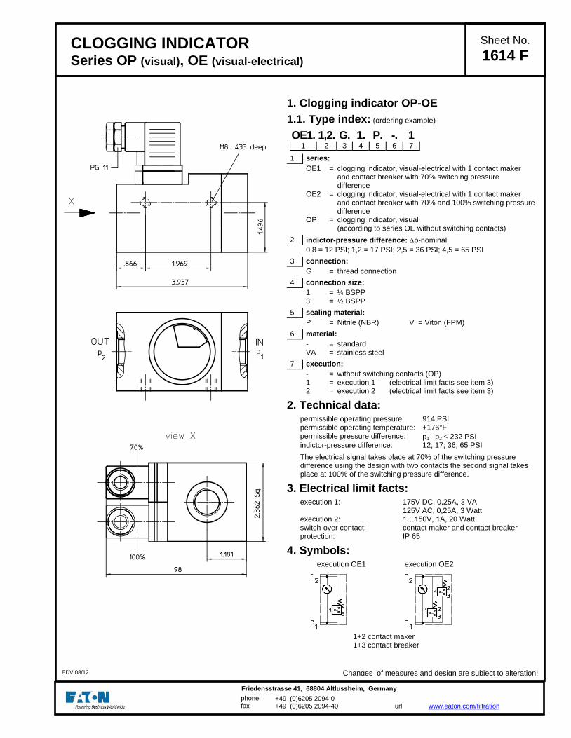
CLOGGING INDICATOR Series OP (visual), OE (visual-electrical)
Sheet No.
1614 F
1. Clogging indicator OP-OE
1.1. Type index: (ordering example)
OE1. 1,2. G. 1. P. -. 1 1 2 3 4 5 6 7
1 series:
OE1 = clogging indicator, visual-electrical with 1 contact maker and contact breaker with 70% switching pressure difference
OE2 = clogging indicator, visual-electrical with 1 contact maker and contact breaker with 70% and 100% switching pressure difference
OP = clogging indicator, visual (according to series OE without switching contacts)
2 indictor-pressure difference: p-nominal
0,8 = 12 PSI; 1,2 = 17 PSI; 2,5 = 36 PSI; 4,5 = 65 PSI 3 connection:
G = thread connection 4 connection size:
1 = ¼ BSPP 3 = ½ BSPP 5 sealing material:
P = Nitrile (NBR) V = Viton (FPM) 6 material:
- = standard VA = stainless steel 7 execution:
- = without switching contacts (OP) 1 = execution 1 (electrical limit facts see item 3) 2 = execution 2 (electrical limit facts see item 3)
2. Technical data:
permissible operating pressure: 914 PSI permissible operating temperature: +176°F permissible pressure difference: p1 - p2 232 PSI indictor-pressure difference: 12; 17; 36; 65 PSI
The electrical signal takes place at 70% of the switching pressure difference using the design with two contacts the second signal takes place at 100% of the switching pressure difference.
3. Electrical limit facts:
execution 1: 175V DC, 0,25A, 3 VA 125V AC, 0,25A, 3 Watt
execution 2: 1…150V, 1A, 20 Watt switch-over contact: contact maker and contact breaker protection: IP 65
4. Symbols:
execution OE1 execution OE2
1+2 contact maker 1+3 contact breaker
Changes of measures and design are subject to alteration! EDV 08/12
+49 (0)6205 2094-0 +49 (0)6205 2094-40
phone fax
Friedensstrasse 41, 68804 Altlussheim, Germany
url
www.eaton.com/filtration

5. Functioning:
The clogging indicator OE is a combined visual and electrical pressure difference indicator.
This type of pressure difference indicator can be mounted on all pressure filters with operating pressure 914 PSI, if the corresponding measuring ports on the filter housing are available. With contamination of the filter element the difference between the supply pressure and the output pressure of the filter is increasing. Depending on this pressure difference but independent of the operating pressure, visual and electrical signals are released. A pressure difference dependent measuring piston, charged with supply pressure and output pressure, moves towards a measuring spring. Concerning the OE1 a permanent magnet which is integrated in the measuring piston switches - depending on the gauge length - a Reed-contact (magnetic-switch) and releases electrical control signals upon reaching a pressure difference of 70%. The OE2 is equiped with two magnetic switches which release electrical control signals in a sequence of 70% and 100% of the switching pressure. The visual control signal is indicated by a blue-red scale which is connected to the magnetic measuring piston. In the range of low pressure differences - depending on the gauge length of the measuring piston - the blue range of the scale appears first. The indicated switching pressure difference is reached when the dividing line between the red and the blue range of the scale points to the marking on the display window.
6. Operating instruction:
- Connection
Upon connecting the indicator to the filter make sure that the connection marked „+“ is connected to the dirt oil side (IN) and the connection marked „-“ is connected to the clean oil side (OUT). Note: Consider data and connecting conditions mentioned in items 2 to 4.
7. Maintenance:
The device is maintenance-free. However, make sure that no solvents get in touch with the display window visual indicator nor with the piston-spring-system of the clogging indicator.
US 1614 F
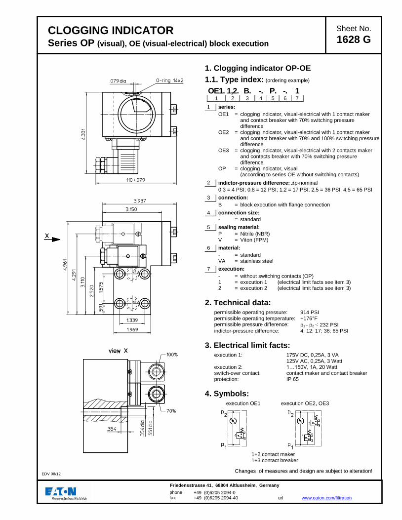
CLOGGING INDICATOR Series OP (visual), OE (visual-electrical) block execution
Sheet No.
1628 G
1. Clogging indicator OP-OE
1.1. Type index: (ordering example)
OE1. 1,2. B. -. P. -. 1 1 2 3 4 5 6 7
1 series:
OE1 = clogging indicator, visual-electrical with 1 contact maker and contact breaker with 70% switching pressure difference
OE2 = clogging indicator, visual-electrical with 1 contact maker and contact breaker with 70% and 100% switching pressure difference
OE3 = clogging indicator, visual-electrical with 2 contacts maker and contacts breaker with 70% switching pressure difference
OP = clogging indicator, visual (according to series OE without switching contacts)
2 indictor-pressure difference: p-nominal
0,3 = 4 PSI; 0,8 = 12 PSI; 1,2 = 17 PSI; 2,5 = 36 PSI; 4,5 = 65 PSI 3 connection:
B = block execution with flange connection 4 connection size:
- = standard 5 sealing material:
P = Nitrile (NBR) V = Viton (FPM) 6 material:
- = standard VA = stainless steel 7 execution:
- = without switching contacts (OP) 1 = execution 1 (electrical limit facts see item 3) 2 = execution 2 (electrical limit facts see item 3)
2. Technical data:
permissible operating pressure: 914 PSI permissible operating temperature: +176°F permissible pressure difference: p1 - p2 232 PSI indictor-pressure difference: 4; 12; 17; 36; 65 PSI
3. Electrical limit facts:
execution 1: 175V DC, 0,25A, 3 VA 125V AC, 0,25A, 3 Watt
execution 2: 1…150V, 1A, 20 Watt switch-over contact: contact maker and contact breaker protection: IP 65
4. Symbols:
execution OE1 execution OE2, OE3
1+2 contact maker 1+3 contact breaker
Changes of measures and design are subject to alteration! EDV 08/12
+49 (0)6205 2094-0 +49 (0)6205 2094-40
phone
fax
Friedensstrasse 41, 68804 Altlussheim, Germany
url
www.eaton.com/filtration

5. Functioning:
The clogging indicator OE is a combined visual and electrical pressure difference indicator.
This type of pressure difference indicator can be mounted on all pressure filters with operating pressure 914 PSI, if the corresponding measuring ports on the filter housing are available. With contamination of the filter element the difference between the supply pressure and the output pressure of the filter is increasing. Depending on this pressure difference but independent of the operating pressure, visual and electrical signals are released. A pressure difference dependent measuring piston, charged with supply pressure and output pressure, moves towards a measuring spring. Concerning the OE1 a permanent magnet which is integrated in the measuring piston switches - depending on the gauge length - a Reed-contact (magnetic-switch) and releases electrical control signals upon reaching a pressure difference of 70%. The OE2 is equiped with two magnetic switches which release electrical control signals in a sequence of 70% and 100% of the switching pressure. The OE3 is equiped with two magnetic switches triggering electrical control signals at 70% of the switching pressure (redudance of the switches). The visual control signal is indicated by a blue-red scale which is connected to the magnetic measuring piston. In the range of low pressure differences - depending on the gauge length of the measuring piston - the blue range of the scale appears first. The indicated switching pressure difference is reached when the dividing line between the red and the blue range of the scale points to the marking on the display window.
6. Operating instruction:
Note: Consider data and connecting conditions mentioned in items 2 to 4.
7. Maintenance:
The device is maintenance-free. However, make sure that no solvents get in touch with the display window visual indicator nor with the piston-spring-system of the clogging indicator.
US 1628 G

1. Type index: (ordering example)
VS5. 1,5. V. -. NO. CS. B. - 1 2 3 4 5 6 7 8
1 series: VS5 = electronical clogging indicator with analog
output 6...20mA and 2x PNP-switching contacts (75% and 100%)
2 indicator-pressure difference: p-nominal 1,5 = 22 PSI 5,0 = 73 PSI 2,5 = 36 PSI 6,0 = 87 PSI 3 sealing material: P = Nitrile (NBR) V = Viton (FPM) 4 material:(block) - = standard (aluminium) VA = stainless steel 5 contact: NO = normally opened, NC = normally closed 6 cold start: CS = with cold start suppression up to 77°F - = without cold start suppression 7 execution: B = block execution 8 connection: - = without GS5 = M12, 8-pole female connector SS5 = M12, 8-pol. female connector with 197 inch cable and
3 installed LED’s red/yellow/green (only in combination with contact “NO = normally opened”)
2. Technical data: max. operating pressure: 6000 PSI (stainless steel) 3200 PSI (aluminium) max. pressure difference: 2320 PSI operating temperature: -40°F…176FC temperature range of fluid: -13°F…212°F (NBR)
14°F…212°F (FPM) other temperature ranges on request
sealing material: NBR / FPM, further seals on request power voltage: +24VDC ±20% current consumption: approx.. 25mA + current signal output
(measured with 24VDC) output signal: p: 6...20mA, max load: 400
5mA by cold start suppression 75% and 100% from pnominal as 24VDC
error of measurement: 5% v. pnominal operating ability: 400mA at closed state
1mA at opened state protection: IP65 (IP67 on request)
Changes of measures and design are subject to alteration!
ELECTRONICAL CLOGGING INDICATOR Series VS5 (block execution)
Sheet No. 1641 A
EDV 07/15
3. Spare parts:
item qty. designation dimension article-no. 1 3 O-ring 14 x 2 304342 (NBR) 304722 (FPM) 2 1 O-ring 22 x 2 304708 (NBR) 304721 (FPM)
Configuration of M12 connector at VS5
Connection configuration
+49 (0)6205 2094-0 +49 (0)6205 2094-40
phone fax
Friedensstrasse 41, 68804 Altlussheim, Germany url
www.eaton.com/filtration

4. Functions:
- continuous pressure difference measuring - cold start indication up to approx. + 77°F - suppression of pressure peaks - dust-proof and splash-proof aluminium or stainless steel housing - interference-free signal transmission over longer distances - optimal utilization of the filter elements based on a high definition of the measure value within the final measure range - interchangeable with clogging indicator type AE
5. Connection: GS5 = M12, 8-pole female connector (article-no. 345742) temperature range: -40°F … +176°F
SS5 = M12, 8-pole female connector with 197 inch cable and 3 installed LED’s red/yellow/green (article-no. 347370) temperature range: -13°F … +176°C
6. Accessories: (spare part for VS1 / VS2) - an adapter plug GSA1 (article-no. 347425) is required when replacing a VS1 through the VS5 - an adapter plug GSA2 (article-no. 347428) is required when replacing a VS2 through the VS5
US 1641 A
Connection configuration

1. Type index: (ordering example)
VS5. 1,5. V. -. NO. CS. -. - 1 2 3 4 5 6 7 8
1 series: VS5 = electronical clogging indicator with analog
output 6...20mA and 2x PNP-switching contacts (75% and 100%)
2 indicator-pressure difference: p-nominal 1,5 = 22 PSI 5,0 = 73 PSI 2,5 = 36 PSI 6,0 = 87 PSI 3 sealing material: P = Nitrile (NBR) V = Viton (FPM) 4 material:(screw-in-housing) - = standard (aluminium) VA = stainless steel 5 contact: NO = normally opened, NC = normally closed 6 cold start: CS = with cold start suppression up to 77°F - = without cold start suppression 7 execution: - = standard 8 connection: - = without GS5 = M12, 8-pole female connector SS5 = M12, 8-pol. female connector with 197 inch cable and
3 installed LED’s red/yellow/green (only in combination with contact “NO = normally opened”)
2. Technical data: max. operating pressure: 6000 PSI (stainless steel) 3200 PSI (aluminium) max. pressure difference: 2320 PSI operating temperature: -40°F…176FC temperature range of fluid: -13°F…212°F (NBR)
14°F…212°F (FPM) other temperature ranges on request
sealing material: NBR / FPM, further seals on request power voltage: +24VDC ±20% current consumption: approx.. 25mA + current signal output
(measured with 24VDC) output signal: p: 6...20mA, max load: 400
5mA by cold start suppression 75% and 100% from pnominal as 24VDC
error of measurement: 5% v. pnominal operating ability: 400mA at closed state
1mA at opened state protection: IP65 (IP67 on request)
fatigue strength: max. 1 Mio load cycles for aluminium
Changes of measures and design are subject to alteration!
ELECTRONICAL CLOGGING INDICATOR Series VS5 (thread execution)
Sheet No. 1619 C
EDV 07/15
3. Spare parts:
item qty. designation dimension article-no. 1 1 O-ring 14 x 2 304342 (NBR) 304722 (FPM) 2 1 O-ring 22 x 2 304708 (NBR) 304721 (FPM)
Configuration of M12 connector at VS5
Connection configuration
+49 (0)6205 2094-0 +49 (0)6205 2094-40
phone fax
Friedensstrasse 41, 68804 Altlussheim, Germany url
www.eaton.com/filtration

4. Functions:
- continuous pressure difference measuring - cold start indication up to approx. + 77°F - suppression of pressure peaks - dust-proof and splash-proof aluminium or stainless steel housing - interference-free signal transmission over longer distances - optimal utilization of the filter elements based on a high definition of the measure value within the final measure range - interchangeable with clogging indicator type AE
5. Connection: GS5 = M12, 8-pole female connector (article-no. 345742) temperature range: -40°F … +176°F
SS5 = M12, 8-pole female connector with 197 inch cable and 3 installed LED’s red/yellow/green (article-no. 347370) temperature range: -13°F … +176°C
6. Accessories: (spare part for VS1 / VS2) - an adapter plug GSA1 (article-no. 347425) is required when replacing a VS1 through the VS5 - an adapter plug GSA2 (article-no. 347428) is required when replacing a VS2 through the VS5
US 1619 C
Connection configuration


