
iglide® A181• Compliant with EC Directive 10/2011 EC
• FDA compliant
• Universally applicable
• Good media resistance
• Wear resistant
431

Compliant with EC Directive 10/2011 EC
Compliant with FDA regulations
Good media resistance
iglide®
A181 iglide® A181 - FDA and EC Directive compliantFood grade material
l If FDA compliance is requiredl When 10/2011 EC Directive compliance is requiredl When a material suitable for direct contact with food
or pharmaceuticals is required
l When FDA compliance or 10/2011 EC Directive is not needed
➤ iglide® Jl When temperatures are continuously greater than
194°F ➤ iglide® A350l When a cost-effective universal bearing is desired ➤ iglide® G300 ➤ iglide® P
Bearings made of iglide® A181 are suitable for application in direct contact with food. Therefore, they are the ideal solution for bearing applications on machines for the food and packaging industries, medical equipment manufacturing, and for small equipment for households, etc. The blue color also facilitates the often required “optical detectability” in the food industry.
max. +194°Fmin. –58°FF
Available from stock Detailed information about delivery time online.
l Food industryl Beverage technologyl Medical etc.
Ø 6 to 20 mmmore dimensions on requestmm
Typical application areas
Price breaks online No minimum order.$
Lifetime calculation, configuration and more ➤ www.igus.com/A181
Universally applicable
432
iglide® A181 material complies with EC Directive 10/2011 EC and also with FDA (Food and Drug Administration) specifications for repeated contact with food.

iglide®
A181
4333D-CAD files, prices and delivery time ➤ www.igus.com/A181
iglide® A181 - Technical Data
Maximum surface speeds
Material Properties Table
General Properties Unit iglide® A181 Testing MethodDensity g/cm3 1.38Color blueMax. moisture absorption at 73°F / 50% r.h. % weight 0.2 DIN 53495Max. moisture absorption % weight 1.3Coefficient of friction, dynamic against steel µ 0.10 - 0.21pv value, max. (dry) psi x fpm 8,750
Mechanical PropertiesModulus of elasticity psi 277,500 DIN 53457Tensile strength at 68°F psi 6,962 DIN 53452Compressive strength psi 8,702Permissible static surface pressure (68°F) psi 4,496Shore D-hardness 76 DIN 53505
Physical and Thermal PropertiesMax. long-term application temperature °F 194Max. application temperature, short-term °F 230Min. application temperature °F -58Thermal conductivity W/m x K 0.25 ASTM C 177Coefficient of thermal expansion K-1 x 10⁻⁵ 11 DIN 53752
Electrical PropertiesSpecific volume resistance Ωcm < 1012 DIN IEC 93Surface resistance Ω < 1012 DIN 53482
Pre
ssur
e (p
si)
Surface Speed (fpm)
.197 1.97 19.7 197 1,96914.5
145
1,450
14,500
Permissible pv values for iglide® A181 running dry against a steel shaft, at 68°F
Compressive StrengthWith increasing temperatures, the compressive strength of iglide® A181 plain bearings decreases. The recommended maximum surface pressure is a mechanical material para meter. No conclusions regarding the tribological properties can be drawn from this.The graph at the right shows the elastic deformation of iglide® A181 during radial loading. At the recommended maximum surface pressure of 4,496 psi the deformation is less than 3 %.Plastic deformation is minimal up to this radial load. However, it is also a result of the service time.
➤ Compressive strength, Page 63 Deformation under load and temperature
1
234
5
6
7
8
9
10
00 725 1,450 2,176 2,901 3,626 4,351 5,076
Pressure (psi)
140°F 73°F
Def
orm
atio
n in
%
Permissible Surface Speeds
iglide® A181 is developed for low surface speeds. Maximum speeds up to 158 fpm (rotating) and 689 fpm (linear) respectively are permitted for continuous use in dry operation. These given values indicate the limits at which an increase up to the continuous permissible temperature occurs. In practice these limit values are not always reached due to interactions.
➤ Surface speed, Page 64 ➤ pv value, Page 65
Continuous Short Term
fpm fpm
Rotating 158 236
Oscillating 118 197
Linear 689 984
434
iglide®
A181
Lifetime calculation, configuration and more ➤ www.igus.com/A181
iglide® A181 - Technical Data
0,26
0,23
0,20
0,17
0,14
0,11
0,08
0,050 725 1,450 2,176 2,901 3,626 4,351
Co
effic
ient
of
fric
tion
µ
Load (psi)
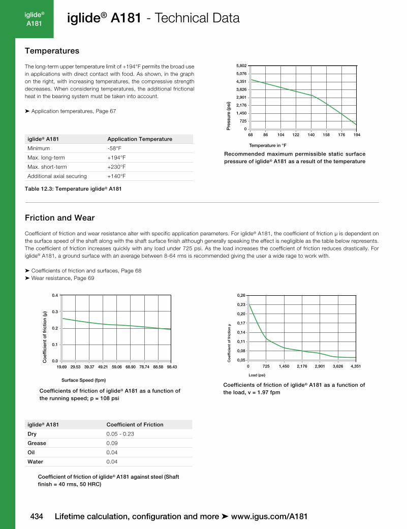
Coefficients of friction of iglide® A181 as a function of the load, v = 1.97 fpm
Coefficient of friction of iglide® A181 against steel (Shaft finish = 40 rms, 50 HRC)
0.0
0.2
0.4
19.69 29.53 39.37 49.21 59.06 98.43
0.1
0.3
68.90 78.74 88.58
Co
effic
ient
of
fric
tion
(µ)
Surface Speed (fpm)
Coefficients of friction of iglide® A181 as a function of the running speed; p = 108 psi
Friction and Wear
Coefficient of friction and wear resistance alter with specific application parameters. For iglide® A181, the coefficient of friction µ is dependent on the surface speed of the shaft along with the shaft surface finish although generally speaking the effect is negligible as the table below represents. The coefficient of friction increases quickly with any load under 725 psi. As the load increases the coefficient of friction reduces drastically. For iglide® A181, a ground surface with an average between 8-64 rms is recommended giving the user a wide rage to work with.
➤ Coefficients of friction and surfaces, Page 68 ➤ Wear resistance, Page 69
Temperatures
The long-term upper temperature limit of +194°F permits the broad use in applications with direct contact with food. As shown, in the graph on the right, with increasing temperatures, the compressive strength decreases. When considering temperatures, the additional frictional heat in the bearing system must be taken into account.
➤ Application temperatures, Page 67
Table 12.3: Temperature iglide® A181
68 122 176 1940
725
1,450
2,176
2,901
3,626
4,351
5,076
5,802
86 140104 158
Temperature in °F
Pre
ssur
e (p
si)
Recommended maximum permissible static surface pressure of iglide® A181 as a result of the temperature
iglide® A181 Application Temperature
Minimum -58°F
Max. long-term +194°F
Max. short-term +230°F
Additional axial securing +140°F
iglide® A181 Coefficient of Friction
Dry 0.05 - 0.23
Grease 0.09
Oil 0.04
Water 0.04

iglide®
A181
4353D-CAD files, prices and delivery time ➤ www.igus.com/A181
iglide® A181 - Technical Data
Installation Tolerancesiglide® A181 plain bearings are meant to be oversized before being pressfit. After proper installation into a recommended housing bore, the inner diameter adjusts to meet our specified tolerances. Please adhere to the catalog specifications for housing bore and recommended shaft sizes. This will help to ensure optimal performance of iglide® plain bearings.
➤ Tolerance table, Page 75 ➤ Testing methods, Page 76
.0197”(0.5 mm)
b1
A
30°
f
A
Length of chamfer Length30°
Wear of iglide® A181, rotating applications with different shaft materials, p = 145 psi, v = 59 fpm
0.0
0.5
1.0
1.5
2.0
2.5
3.0
Har
d a
nod
ized
alu
min
um
Aut
om
atic
scr
ew s
teel
1050
Ste
el
1050
, har
d c
hro
med
HR
Car
bo
n S
teel
304
Sta
inle
ss
440B
Ste
el
Wea
r (µ
m/k
m)
0
20
40
60
80
100
120
0 725 1,450 2,176 2,901 3,626 4,351
Wea
r (µ
m/k
m)
Pressure (psi)
Rotating Oscillating
0
5.0
4.0
3.0
725580435290145
1.0
2.0
Pressure (psi)
Wea
r (µ
m/k
m)
1050 Steel
440B Hardened Steel
Hard anodized Aluminum
1050, Hard chromed
Wear of iglide® A181 with different shaft materials in rotational applications
Wear with different shaft materials, oscillating and rotating movement p = 290 psi
Shaft Materials
The graphs show the test results of iglide® A181 bearings running against various shaft materials.Particular attention is paid in the food industry to the corrosion-resistant shafts. The chart below shows that very low wear rates can be achieved in combination with these shafts. As with many of the iglide® materials, wear rate increases with otherwise identical parameters in rotation.
➤ Shaft Materials, Page 71
For Inch Size Bearings
Length Tolerance (b1)Length of Chamfer (f)
Based on d1Length(inches)
Tolerance (h13)(inches)
0.1181 to 0.2362 -0.0000 /-0.0071 f = .012 ➝ d1 .040” - .236”
f = .019 ➝ d1 > .236” - .472”
f = .031 ➝ d1 > .472” - 1.18”
f = .047 ➝ d1 > 1.18”
0.2362 to 0.3937 -0.0000 /-0.00870.3937 to 0.7086 -0.0000 /-0.01060.7086 to 1.1811 -0.0000 /-0.01301.1811 to 1.9685 -0.0000 /-0.01541.9685 to 3.1496 -0.0000 /-0.0181
For Metric Size Bearings
Length Tolerance (b1)Length of Chamfer (f)
Based on d1Length
(mm)Tolerance (h13)
(mm)
1 to 3 -0 /-140 f = 0.3 ➝ d1 1 - 6 mmf = 0.5 ➝ d1 > 6 - 12 mmf = 0.8 ➝ d1 > 12 - 30 mmf = 1.2 ➝ d1 > 30 mm
> 3 to 6 -0 /-180> 6 to 10 -0 /-220>10 to 18 -0 /-270>18 to 30 -0 /-330>30 to 50 -0 /-390>50 to 80 -0 /-460

436
iglide®
A181
Lifetime calculation, configuration and more ➤ www.igus.com/A181
iglide® A181 - Technical Data
Electrical properties of iglide® A181
Electrical Properties
iglide® A181 bearings are electrically insulating.
Vacuum
When used in a vacuum environment, the iglide® A181 bearings release moisture as a vapor. Therefore, only dehumidified bearings are suitable in a vacuum environment.
UV-Resistance
iglide® A181 bearings are only conditionally resistant to UV radiation.
Radiation Resistance
Plain bearings made of iglide® A181 are resistant to radiation up to an intensity of 2 · 102 Gy.
0.00
0.02
0.04
0.06
0.08
0.10
0.00 0.13 0.26 0.39 0.52 0.65 0.78 0.91 1.04 1.17 1.30
Red
uctio
n o
f th
e in
ner
dia
met
er (%
)
Moisture absorption (weight %)
Effect of moisture absorption on iglide® A181 plain bearings
Chemical & Moisture Resistance
iglide® A181 bearings can be used under various environmental conditions and in contact with numerous chemicals. The table gives an overview of the chemical resistance of iglide® A181 bearings at room temperature. The moisture absorption of iglide® A181 bearings is approximately 0.2% in standard atmosphere. The saturation limit submerged in water is 1.3%. This must be taken into account for these types of applications.
➤ Chemical table, Page 1364
Chemical resistance of iglide® A181 All data given concerns the chemical resistance at room temperature (68°F). For a complete list, see Page 1364
Medium Resistance
Alcohol +
Hydrocarbon, chlorinated +
Greases, oils without additives +
Fuels +
Weak acids 0 to –
Strong acids –
Weak alkaline +
Strong alkaline + to 0
+ resistant, 0 conditionally resistant, – not resistant
iglide® A181
Specific volume resistance > 1012 Ωcm
Surface resistance > 1012 Ω

iglide®
A181
437
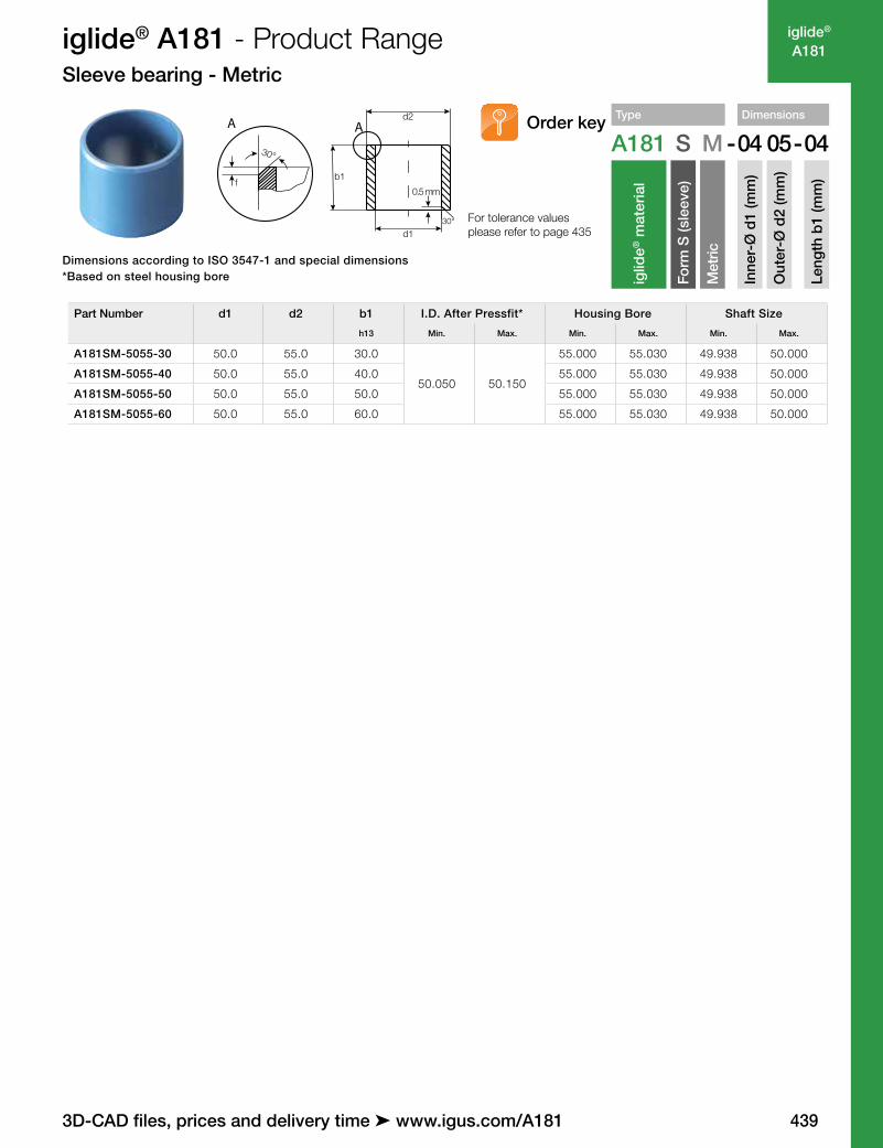
iglide® A181 - Product RangeSleeve bearing - Metric
Type Dimensions
A181 S M -04 05-04
iglid
e® m
ater
ial
Form
S (s
leev
e)
Met
ric
Inne
r-Ø
d1
(mm
)
Out
er-Ø
d2
(mm
)
Leng
th b
1 (m
m)
Order key
0.5 mm
30°
fb1
d1
d2AA
30° For tolerance values please refer to page 435
Dimensions according to ISO 3547-1 and special dimensions*Based on steel housing bore
3D-CAD files, prices and delivery time ➤ www.igus.com/A181
Part Number d1 d2 b1 I.D. After Pressfit* Housing Bore Shaft Size
h13 Min. Max. Min. Max. Min. Max.
A181SM-0405-04 4.0 5.0 4.04.020 4.068
4.000 4.012 3.970 4.000
A181SM-0405-06 4.0 5.0 6.0 5.000 5.012 3.970 4.000
A181SM-0507-05 5.0 7.0 5.05.020 5.068
7.000 7.015 4.970 5.000
A181SM-0507-10 5.0 7.0 10.0 7.000 7.015 4.970 5.000
A181SM-0608-06 6.0 8.0 6.0
6.020 6.068
8.000 8.015 5.970 6.000
A181SM-0608-08 6.0 8.0 8.0 8.000 8.015 5.970 6.000
A181SM-0608-10 6.0 8.0 10.0 8.000 8.015 5.970 6.000
A181SM-0810-08 8.0 10.0 8.0
8.025 8.083
10.000 10.015 7.964 8.000
A181SM-0810-10 8.0 10.0 10.0 10.000 10.015 7.964 8.000
A181SM-0810-12 8.0 10.0 12.0 10.000 10.015 7.964 8.000
A181SM-1012-08 10.0 12.0 8.0
10.025 10.083
12.000 12.018 9.964 10.000
A181SM-1012-10 10.0 12.0 10.0 12.000 12.018 9.964 10.000
A181SM-1012-12 10.0 12.0 12.0 12.000 12.018 9.964 10.000
A181SM-1012-15 10.0 12.0 15.0 12.000 12.018 9.964 10.000
A181SM-1012-20 10.0 12.0 20.0 12.000 12.018 9.964 10.000
A181SM-1214-10 12.0 14.0 10.0
12.032 12.102
14.000 14.018 11.957 12.000
A181SM-1214-12 12.0 14.0 12.0 14.000 14.018 11.957 12.000
A181SM-1214-15 12.0 14.0 15.0 14.000 14.018 11.957 12.000
A181SM-1214-20 12.0 14.0 20.0 14.000 14.018 11.957 12.000
A181SM-1315-10 13.0 15.0 10.0 15.000 15.018 12.957 13.000
A181SM-1315-20 13.0 15.0 20.0 15.000 15.018 12.957 13.000
A181SM-1416-15 14.0 16.0 15.0
14.032 14.102
16.000 16.018 13.957 14.000
A181SM-1416-20 14.0 16.0 20.0 16.000 16.018 13.957 14.000
A181SM-1416-25 14.0 16.0 25.0 16.000 16.018 13.957 14.000
A181SM-1517-15 15.0 17.0 15.0
15.032 15.102
17.000 17.018 14.957 15.000
A181SM-1517-20 15.0 17.0 20.0 17.000 17.018 14.957 15.000
A181SM-1517-25 15.0 17.0 25.0 17.000 17.018 14.957 15.000
A181SM-1618-15 16.0 18.0 15.0
16.032 16.102
18.000 18.018 15.957 16.000
A181SM-1618-20 16.0 18.0 15.0 18.000 18.018 15.957 16.000
A181SM-1618-25 16.0 18.0 25.0 18.000 18.018 15.957 16.000
A181SM-1820-15 18.0 20.0 15.0
18.032 18.102
20.000 20.021 17.957 18.000
A181SM-1820-20 18.0 20.0 20.0 20.000 20.021 17.957 18.000
A181SM-1820-25 18.0 20.0 25.0 20.000 20.021 17.957 18.000
A181SM-2023-10 20.0 23.0 10.0
20.040 20.124
23.000 23.021 19.948 20.000
A181SM-2023-15 20.0 23.0 15.0 23.000 23.021 19.948 20.000
A181SM-2023-20 20.0 23.0 20.0 23.000 23.021 19.948 20.000
A181SM-2023-25 20.0 23.0 25.0 23.000 23.021 19.948 20.000

438
iglide®
A181 iglide® A181 - Product RangeSleeve bearing - Metric
0.5 mm
30°
fb1
d1
d2AA
30° For tolerance values please refer to page 435
Type Dimensions
A181 S M -04 05-04
iglid
e® m
ater
ial
Form
S (s
leev
e)
Met
ric
Inne
r-Ø
d1
(mm
)
Out
er-Ø
d2
(mm
)
Leng
th b
1 (m
m)
Order key
Dimensions according to ISO 3547-1 and special dimensions*Based on steel housing bore
Lifetime calculation, configuration and more ➤ www.igus.com/A181
Part Number d1 d2 b1 I.D. After Pressfit* Housing Bore Shaft Size
h13 Min. Max. Min. Max. Min. Max.
A181SM-2023-30 20.0 23.0 30.0 20.040 20.124 23.000 23.021 19.948 20.000
A181SM-2225-15 22.0 25.0 15.0
22.040 22.124
25.000 25.021 21.948 22.000
A181SM-2225-20 22.0 25.0 20.0 25.000 25.021 21.948 22.000
A181SM-2225-25 22.0 25.0 25.0 25.000 25.021 21.948 22.000
A181SM-2225-30 22.0 25.0 30.0 25.000 25.021 21.948 22.000
A181SM-2427-15 24.0 27.0 15.0
24.040 24.124
27.000 27.021 23.948 24.000
A181SM-2427-20 24.0 27.0 20.0 27.000 27.021 23.948 24.000
A181SM-2427-25 24.0 27.0 25.0 27.000 27.021 23.948 24.000
A181SM-2427-30 24.0 27.0 30.0 27.000 27.021 23.948 24.000
A181SM-2428-30 24.0 28.0 30.0 24.040 24.124 28.000 28.021 23.948 24.000
A181SM-2528-15 25.0 28.0 15.0
25.040 25.124
28.000 28.021 24.948 25.000
A181SM-2528-20 25.0 28.0 20.0 28.000 28.021 24.948 25.000
A181SM-2528-25 25.0 28.0 25.0 28.000 28.021 24.948 25.000
A181SM-2528-30 25.0 28.0 30.0 28.000 28.021 24.948 25.000
A181SM-2832-20 28.0 32.0 20.0
28.040 28.124
32.000 32.025 27.948 28.000
A181SM-2832-25 28.0 32.0 25.0 32.000 32.025 27.948 28.000
A181SM-2832-30 28.0 32.0 30.0 32.000 32.025 27.948 28.000
A181SM-3034-20 30.0 34.0 20.0
30.040 30.124
34.000 34.025 29.948 30.000
A181SM-3034-25 30.0 34.0 25.0 34.000 34.025 29.948 30.000
A181SM-3034-30 30.0 34.0 30.0 34.000 34.025 29.948 30.000
A181SM-3034-40 30.0 34.0 40.0 34.000 34.025 29.948 30.000
A181SM-3236-20 32.0 36.0 20.0
32.050 32.150
36.000 36.025 31.938 32.000
A181SM-3236-30 32.0 36.0 30.0 36.000 36.025 31.938 32.000
A181SM-3236-40 32.0 36.0 40.0 36.000 36.025 31.938 32.000
A181SM-3539-20 35.0 39.0 20.0
35.050 35.150
39.000 39.025 34.938 35.000
A181SM-3539-30 35.0 39.0 30.0 39.000 39.025 34.938 35.000
A181SM-3539-40 35.0 39.0 40.0 39.000 39.025 34.938 35.000
A181SM-3539-50 35.0 39.0 50.0 39.000 39.025 34.938 35.000
A181SM-4044-20 40.0 44.0 20.0
40.050 40.150
44.000 44.025 39.938 40.000
A181SM-4044-30 40.0 44.0 30.0 44.000 44.025 39.938 40.000
A181SM-4044-40 40.0 44.0 40.0 44.000 44.025 39.938 40.000
A181SM-4044-50 40.0 44.0 50.0 44.000 44.025 39.938 40.000
A181SM-4550-20 45.0 50.0 20.0
45.050 50.150
50.000 50.025 44.938 45.000
A181SM-4550-30 45.0 50.0 30.0 50.000 50.025 44.938 45.000
A181SM-4550-40 45.0 50.0 40.0 50.000 50.025 44.938 45.000
A181SM-4550-50 45.0 50.0 50.0 50.000 50.025 44.938 45.000
A181SM-5055-20 50.0 55.0 20.0 50.050 50.150 55.000 55.030 49.938 50.000
iglide®
A181
439
iglide® A181 - Product RangeSleeve bearing - Metric
Type Dimensions
A181 S M -04 05-04
iglid
e® m
ater
ial
Form
S (s
leev
e)
Met
ric
Inne
r-Ø
d1
(mm
)
Out
er-Ø
d2
(mm
)
Leng
th b
1 (m
m)
Order key
0.5 mm
30°
fb1
d1
d2AA
30° For tolerance values please refer to page 435
Dimensions according to ISO 3547-1 and special dimensions*Based on steel housing bore
3D-CAD files, prices and delivery time ➤ www.igus.com/A181
Part Number d1 d2 b1 I.D. After Pressfit* Housing Bore Shaft Size
h13 Min. Max. Min. Max. Min. Max.
A181SM-5055-30 50.0 55.0 30.0
50.050 50.150
55.000 55.030 49.938 50.000
A181SM-5055-40 50.0 55.0 40.0 55.000 55.030 49.938 50.000
A181SM-5055-50 50.0 55.0 50.0 55.000 55.030 49.938 50.000
A181SM-5055-60 50.0 55.0 60.0 55.000 55.030 49.938 50.000

440
iglide®
R
Lifetime calculation, configuration and more ➤ www.igus.com/A181
iglide®
A181
r = max. 0.5
iglide® A181 - Product RangeFlange bearing - Metric
d3
d1
d2
b1r
30°
f
A A
b2For tolerance values please refer to page 435
Type Dimensions
A181 F M -01 03-02
iglid
e® m
ater
ial
Form
F (fl
ange
)
Met
ric
Inne
r-Ø
d1
(mm
)
Out
er-Ø
d2
(mm
)
Leng
th b
1 (m
m)
Order key
Dimensions according to ISO 3547-1 and special dimensions*Based on steel housing bore
Part Number d11) d2 d3 b1 b2 I.D. After Pressfit* Housing Bore Shaft Size
d13 h13 -0.14 Min. Max. Min. Max. Min. Max.
A181FM-0608-04 6.0 8.0 12.0 4.0 1.0
6.020 6.068
8.000 8.015 5.970 6.000
A181FM-0608-06 6.0 8.0 12.0 6.0 1.0 8.000 8.015 5.970 6.000
A181FM-0608-08 6.0 8.0 12.0 8.0 1.0 8.000 8.015 5.970 6.000
A181FM-0810-05 8.0 10.0 15.0 5.5 1.0
8.025 8.083
10.000 10.015 7.964 8.000
A181FM-0810-07 8.0 10.0 15.0 7.5 1.0 10.000 10.015 7.964 8.000
A181FM-0810-09 8.0 10.0 15.0 9.5 1.0 10.000 10.015 7.964 8.000
A181FM-0810-10 8.0 10.0 15.0 10.0 1.0 10.000 10.015 7.964 8.000
A181FM-1012-07 10.0 12.0 18.0 7.0 1.0
10.025 10.083
122.000 12.018 9.964 10.000
A181FM-1012-09 10.0 12.0 18.0 9.0 1.0 122.000 12.018 9.964 10.000
A181FM-1012-10 10.0 12.0 18.0 10.0 1.0 12.000 12.018 9.964 10.000
A181FM-1012-12 10.0 12.0 18.0 12.0 1.0 122.000 12.018 9.964 10.000
A181FM-1012-17 10.0 12.0 18.0 17.0 1.0 122.000 12.018 9.964 10.000
A181FM-1214-07 12.0 14.0 20.0 7.0 1.0
12.032 12.102
14.000 14.018 11.957 12.000
A181FM-1214-09 12.0 14.0 20.0 9.0 1.0 14.000 14.018 11.957 12.000
A181FM-1214-12 12.0 14.0 20.0 12.0 1.0 14.000 14.018 11.957 12.000
A181FM-1214-17 12.0 14.0 20.0 17.0 1.0 14.000 14.018 11.957 12.000
A181FM-1416-12 14.0 16.0 22.0 12.0 1.014.032 14.102
16.000 16.018 13.957 14.000
A181FM-1416-17 14.0 16.0 22.0 17.0 1.0 16.000 16.018 13.957 14.000
A181FM-1517-09 15.0 17.0 23.0 9.0 1.0
14.032 14.102
16.000 16.018 13.957 14.000
A181FM-1517-12 15.0 17.0 23.0 12.0 1.0 16.000 16.018 13.957 14.000
A181FM-1517-17 15.0 17.0 23.0 17.0 1.0 16.000 16.018 13.957 14.000
A181FM-1618-12 16.0 18.0 24.0 12.0 1.016.032 16.102
18.000 18.018 15.957 16.000
A181FM-1618-17 16.0 18.0 24.0 17.0 1.0 18.000 18.018 15.957 16.000
A181FM-1820-12 18.0 20.0 26.0 12.0 1.0
18.032 18.102
20.000 20.021 17.957 18.000
A181FM-1820-17 18.0 20.0 26.0 17.0 1.0 20.000 20.021 17.957 18.000
A181FM-1820-22 18.0 20.0 26.0 22.0 1.0 20.000 20.021 17.957 18.000
A181FM-2023-11 20.0 23.0 30.0 11.5 1.5
20.040 20.124
23.000 23.021 19.948 20.000
A181FM-2023-16 20.0 23.0 30.0 16.5 1.5 23.000 23.021 19.948 20.000
A181FM-2023-21 20.0 23.0 30.0 21.5 1.5 23.000 23.021 19.948 20.000
A181FM-2528-11 25.0 28.0 35.0 11.5 1.5
25.040 25.124
28.000 28.021 24.948 25.000
A181FM-2528-16 25.0 28.0 35.0 16.5 1.5 28.000 28.021 24.948 25.000
A181FM-2528-21 25.0 28.0 35.0 21.5 1.5 28.000 28.021 24.948 25.000
A181FM-3034-16 30.0 34.0 42.0 16.0 2.030.040 30.124
34.000 34.025 29.948 30.000
A181FM-3034-26 30.0 34.0 42.0 26.0 2.0 34.000 34.025 29.948 30.000
A181FM-3539-16 35.0 39.0 47.0 16.0 2.035.050 35.150
39.000 39.025 34.938 35.000
A181FM-3539-26 35.0 39.0 47.0 26.0 2.0 39.000 39.025 34.938 35.000
A181FM-4044-30 40.0 44.0 52.0 30.0 2.0
40.050 40.150
44.000 44.025 39.938 40.000
A181FM-4044-40 40.0 44.0 52.0 40.0 2.0 44.000 44.025 39.938 40.000
A181FM-4550-50 45.0 50.0 58.0 50.0 2.5 50.000 50.025 44.938 45.000


