
POWER MIG™ 300
OPERATOR’S MANUAL
IM736-DFebruary, 2004
Safety Depends on YouLincoln arc welding and cuttingequipment is designed and builtwith safety in mind. However, youroverall safety can be increased byproper installation ... and thought-ful operation on your part. DONOT INSTALL, OPERATE ORREPAIR THIS EQUIPMENTWITHOUT READING THISMANUAL AND THE SAFETYPRECAUTIONS CONTAINEDTHROUGHOUT. And, mostimportantly, think before you actand be careful.
For use with machine Code Numbers: 10562, 10952, 10958, 11000, 11097, 11098For use with machine
• Sales and Service through Subsidiaries and Distributors Worldwide •
Cleveland, Ohio 44117-1199 U.S.A. TEL: 216.481.8100 FAX: 216.486.1751 WEB SITE: www.lincolnelectric.com
• World's Leader in Welding and Cutting Products •
Copyright © 2004 Lincoln Global Inc.
This manual covers equipment which is no longer in production by The Lincoln Electric Co. Speci�cations and availability of optional features may have changed.

FOR ENGINEpowered equipment.
1.a. Turn the engine off before troubleshooting and maintenancework unless the maintenance work requires it to be running.
____________________________________________________1.b. Operate engines in open, well-ventilated
areas or vent the engine exhaust fumes outdoors.
____________________________________________________1.c. Do not add the fuel near an open flame
welding arc or when the engine is running.Stop the engine and allow it to cool beforerefueling to prevent spilled fuel from vaporiz-ing on contact with hot engine parts andigniting. Do not spill fuel when filling tank. Iffuel is spilled, wipe it up and do not startengine until fumes have been eliminated.
____________________________________________________1.d. Keep all equipment safety guards, covers and devices in
position and in good repair.Keep hands, hair, clothing andtools away from V-belts, gears, fans and all other movingparts when starting, operating or repairing equipment.
____________________________________________________
1.e. In some cases it may be necessary to remove safetyguards to perform required maintenance. Removeguards only when necessary and replace them when themaintenance requiring their removal is complete.Always use the greatest care when working near movingparts.
___________________________________________________1.f. Do not put your hands near the engine fan.
Do not attempt to override the governor oridler by pushing on the throttle control rodswhile the engine is running.
___________________________________________________1.g. To prevent accidentally starting gasoline engines while
turning the engine or welding generator during maintenancework, disconnect the spark plug wires, distributor cap ormagneto wire as appropriate.
iSAFETYi
ARC WELDING CAN BE HAZARDOUS. PROTECT YOURSELF AND OTHERS FROM POSSIBLE SERIOUS INJURY OR DEATH.KEEP CHILDREN AWAY. PACEMAKER WEARERS SHOULD CONSULT WITH THEIR DOCTOR BEFORE OPERATING.
Read and understand the following safety highlights. For additional safety information, it is strongly recommended that youpurchase a copy of “Safety in Welding & Cutting - ANSI Standard Z49.1” from the American Welding Society, P.O. Box351040, Miami, Florida 33135 or CSA Standard W117.2-1974. A Free copy of “Arc Welding Safety” booklet E205 is availablefrom the Lincoln Electric Company, 22801 St. Clair Avenue, Cleveland, Ohio 44117-1199.
BE SURE THAT ALL INSTALLATION, OPERATION, MAINTENANCE AND REPAIR PROCEDURES AREPERFORMED ONLY BY QUALIFIED INDIVIDUALS.
WARNING
Mar ‘95
ELECTRIC AND MAGNETIC FIELDSmay be dangerous
2.a. Electric current flowing through any conductor causes localized Electric and Magnetic Fields (EMF). Welding current creates EMF fields around welding cables and welding machines
2.b. EMF fields may interfere with some pacemakers, andwelders having a pacemaker should consult their physicianbefore welding.
2.c. Exposure to EMF fields in welding may have other healtheffects which are now not known.
2.d. All welders should use the following procedures in order tominimize exposure to EMF fields from the welding circuit:
2.d.1. Route the electrode and work cables together - Securethem with tape when possible.
2.d.2. Never coil the electrode lead around your body.
2.d.3. Do not place your body between the electrode andwork cables. If the electrode cable is on your right side, the work cable should also be on your right side.
2.d.4. Connect the work cable to the workpiece as close aspossible to the area being welded.
2.d.5. Do not work next to welding power source.
1.h. To avoid scalding, do not remove theradiator pressure cap when the engine ishot.
CALIFORNIA PROPOSITION 65 WARNINGS
Diesel engine exhaust and some of its constituentsare known to the State of California to cause can-cer, birth defects, and other reproductive harm.
The engine exhaust from this product containschemicals known to the State of California to causecancer, birth defects, or other reproductive harm.
The Above For Diesel Engines The Above For Gasoline Engines

iiSAFETYii
ARC RAYS can burn.4.a. Use a shield with the proper filter and cover
plates to protect your eyes from sparks andthe rays of the arc when welding or observingopen arc welding. Headshield and filter lensshould conform to ANSI Z87. I standards.
4.b. Use suitable clothing made from durable flame-resistantmaterial to protect your skin and that of your helpers fromthe arc rays.
4.c. Protect other nearby personnel with suitable, non-flammablescreening and/or warn them not to watch the arc nor exposethemselves to the arc rays or to hot spatter or metal.
ELECTRIC SHOCK cankill.3.a. The electrode and work (or ground) circuits
are electrically “hot” when the welder is on.Do not touch these “hot” parts with your bareskin or wet clothing. Wear dry, hole-free
gloves to insulate hands.
3.b. Insulate yourself from work and ground using dry insulation.Make certain the insulation is large enough to cover your fullarea of physical contact with work and ground.
In addition to the normal safety precautions, if weldingmust be performed under electrically hazardousconditions (in damp locations or while wearing wetclothing; on metal structures such as floors, gratings orscaffolds; when in cramped positions such as sitting,kneeling or lying, if there is a high risk of unavoidable oraccidental contact with the workpiece or ground) usethe following equipment:
• Semiautomatic DC Constant Voltage (Wire) Welder.• DC Manual (Stick) Welder.• AC Welder with Reduced Voltage Control.
3.c. In semiautomatic or automatic wire welding, the electrode,electrode reel, welding head, nozzle or semiautomaticwelding gun are also electrically “hot”.
3.d. Always be sure the work cable makes a good electricalconnection with the metal being welded. The connectionshould be as close as possible to the area being welded.
3.e. Ground the work or metal to be welded to a good electrical(earth) ground.
3.f. Maintain the electrode holder, work clamp, welding cable andwelding machine in good, safe operating condition. Replacedamaged insulation.
3.g. Never dip the electrode in water for cooling.
3.h. Never simultaneously touch electrically “hot” parts ofelectrode holders connected to two welders because voltagebetween the two can be the total of the open circuit voltageof both welders.
3.i. When working above floor level, use a safety belt to protectyourself from a fall should you get a shock.
3.j. Also see Items 6.c. and 8.
Mar ‘95
FUMES AND GASEScan be dangerous.5.a. Welding may produce fumes and gases
hazardous to health. Avoid breathing thesefumes and gases.When welding, keepyour head out of the fume. Use enoughventilation and/or exhaust at the arc to keep
fumes and gases away from the breathing zone. Whenwelding with electrodes which require specialventilation such as stainless or hard facing (seeinstructions on container or MSDS) or on lead orcadmium plated steel and other metals or coatingswhich produce highly toxic fumes, keep exposure aslow as possible and below Threshold Limit Values (TLV)using local exhaust or mechanical ventilation. Inconfined spaces or in some circumstances, outdoors, arespirator may be required. Additional precautions arealso required when welding on galvanized steel.
5.b. Do not weld in locations near chlorinated hydrocarbon vaporscoming from degreasing, cleaning or spraying operations.The heat and rays of the arc can react with solvent vapors toform phosgene, a highly toxic gas, and other irritating prod-ucts.
5.c. Shielding gases used for arc welding can displace air andcause injury or death. Always use enough ventilation,especially in confined areas, to insure breathing air is safe.
5.d. Read and understand the manufacturer’s instructions for thisequipment and the consumables to be used, including thematerial safety data sheet (MSDS) and follow youremployer’s safety practices. MSDS forms are available fromyour welding distributor or from the manufacturer.
5.e. Also see item 1.b.

4
FOR ELECTRICALLYpowered equipment.
8.a. Turn off input power using the disconnectswitch at the fuse box before working onthe equipment.
8.b. Install equipment in accordance with the U.S. NationalElectrical Code, all local codes and the manufacturer’srecommendations.
8.c. Ground the equipment in accordance with the U.S. NationalElectrical Code and the manufacturer’s recommendations.
CYLINDER may explodeif damaged.7.a. Use only compressed gas cylinders
containing the correct shielding gas for theprocess used and properly operatingregulators designed for the gas and
pressure used. All hoses, fittings, etc. should be suitable forthe application and maintained in good condition.
7.b. Always keep cylinders in an upright position securelychained to an undercarriage or fixed support.
7.c. Cylinders should be located:• Away from areas where they may be struck or subjected tophysical damage.
• A safe distance from arc welding or cutting operations andany other source of heat, sparks, or flame.
7.d. Never allow the electrode, electrode holder or any otherelectrically “hot” parts to touch a cylinder.
7.e. Keep your head and face away from the cylinder valve outletwhen opening the cylinder valve.
7.f. Valve protection caps should always be in place and handtight except when the cylinder is in use or connected foruse.
7.g. Read and follow the instructions on compressed gascylinders, associated equipment, and CGA publication P-l,“Precautions for Safe Handling of Compressed Gases inCylinders,” available from the Compressed Gas Association1235 Jefferson Davis Highway, Arlington, VA 22202.
iiiSAFETYiii
Mar ‘95
WELDING SPARKS cancause fire or explosion.6.a. Remove fire hazards from the welding area.
If this is not possible, cover them to preventthe welding sparks from starting a fire.Remember that welding sparks and hot
materials from welding can easily go through small cracksand openings to adjacent areas. Avoid welding nearhydraulic lines. Have a fire extinguisher readily available.
6.b. Where compressed gases are to be used at the job site,special precautions should be used to prevent hazardoussituations. Refer to “Safety in Welding and Cutting” (ANSIStandard Z49.1) and the operating information for theequipment being used.
6.c. When not welding, make certain no part of the electrodecircuit is touching the work or ground. Accidental contactcan cause overheating and create a fire hazard.
6.d. Do not heat, cut or weld tanks, drums or containers until theproper steps have been taken to insure that such procedureswill not cause flammable or toxic vapors from substancesinside. They can cause an explosion even though they havebeen “cleaned”. For information, purchase “RecommendedSafe Practices for the Preparation for Welding and Cutting ofContainers and Piping That Have Held HazardousSubstances”, AWS F4.1 from the American Welding Society(see address above).
6.e. Vent hollow castings or containers before heating, cutting orwelding. They may explode.
6.f. Sparks and spatter are thrown from the welding arc. Wear oilfree protective garments such as leather gloves, heavy shirt,cuffless trousers, high shoes and a cap over your hair. Wearear plugs when welding out of position or in confined places.Always wear safety glasses with side shields when in awelding area.
6.g. Connect the work cable to the work as close to the weldingarea as practical. Work cables connected to the buildingframework or other locations away from the welding areaincrease the possibility of the welding current passingthrough lifting chains, crane cables or other alternate cir-cuits. This can create fire hazards or overheat lifting chainsor cables until they fail.
6.h. Also see item 1.c.
ivSAFETYiv
Mar. ‘93
PRÉCAUTIONS DE SÛRETÉPour votre propre protection lire et observer toutes les instructionset les précautions de sûreté specifiques qui parraissent dans cemanuel aussi bien que les précautions de sûreté générales suiv-antes:
Sûreté Pour Soudage A L’Arc1. Protegez-vous contre la secousse électrique:
a. Les circuits à l’électrode et à la piéce sont sous tensionquand la machine à souder est en marche. Eviter toujourstout contact entre les parties sous tension et la peau nueou les vétements mouillés. Porter des gants secs et sanstrous pour isoler les mains.
b. Faire trés attention de bien s’isoler de la masse quand onsoude dans des endroits humides, ou sur un planchermetallique ou des grilles metalliques, principalement dans les positions assis ou couché pour lesquelles une grandepartie du corps peut être en contact avec la masse.
c. Maintenir le porte-électrode, la pince de masse, le câblede soudage et la machine à souder en bon et sûr étatdefonctionnement.
d.Ne jamais plonger le porte-électrode dans l’eau pour lerefroidir.
e. Ne jamais toucher simultanément les parties sous tensiondes porte-électrodes connectés à deux machines à souderparce que la tension entre les deux pinces peut être letotal de la tension à vide des deux machines.
f. Si on utilise la machine à souder comme une source decourant pour soudage semi-automatique, ces precautionspour le porte-électrode s’applicuent aussi au pistolet desoudage.
2. Dans le cas de travail au dessus du niveau du sol, se protégercontre les chutes dans le cas ou on recoit un choc. Ne jamaisenrouler le câble-électrode autour de n’importe quelle partiedu corps.
3. Un coup d’arc peut être plus sévère qu’un coup de soliel,donc:
a. Utiliser un bon masque avec un verre filtrant appropriéainsi qu’un verre blanc afin de se protéger les yeux du ray-onnement de l’arc et des projections quand on soude ouquand on regarde l’arc.
b. Porter des vêtements convenables afin de protéger lapeau de soudeur et des aides contre le rayonnement del‘arc.
c. Protéger l’autre personnel travaillant à proximité ausoudage à l’aide d’écrans appropriés et non-inflammables.
4. Des gouttes de laitier en fusion sont émises de l’arc desoudage. Se protéger avec des vêtements de protection libresde l’huile, tels que les gants en cuir, chemise épaisse, pan-talons sans revers, et chaussures montantes.
5. Toujours porter des lunettes de sécurité dans la zone desoudage. Utiliser des lunettes avec écrans lateraux dans leszones où l’on pique le laitier.
6. Eloigner les matériaux inflammables ou les recouvrir afin deprévenir tout risque d’incendie dû aux étincelles.
7. Quand on ne soude pas, poser la pince à une endroit isolé dela masse. Un court-circuit accidental peut provoquer unéchauffement et un risque d’incendie.
8. S’assurer que la masse est connectée le plus prés possiblede la zone de travail qu’il est pratique de le faire. Si on placela masse sur la charpente de la construction ou d’autresendroits éloignés de la zone de travail, on augmente le risquede voir passer le courant de soudage par les chaines de lev-age, câbles de grue, ou autres circuits. Cela peut provoquerdes risques d’incendie ou d’echauffement des chaines et descâbles jusqu’à ce qu’ils se rompent.
9. Assurer une ventilation suffisante dans la zone de soudage.Ceci est particuliérement important pour le soudage de tôlesgalvanisées plombées, ou cadmiées ou tout autre métal quiproduit des fumeés toxiques.
10. Ne pas souder en présence de vapeurs de chlore provenantd’opérations de dégraissage, nettoyage ou pistolage. Lachaleur ou les rayons de l’arc peuvent réagir avec les vapeursdu solvant pour produire du phosgéne (gas fortement toxique)ou autres produits irritants.
11. Pour obtenir de plus amples renseignements sur la sûreté,voir le code “Code for safety in welding and cutting” CSAStandard W 117.2-1974.
PRÉCAUTIONS DE SÛRETÉ POURLES MACHINES À SOUDER ÀTRANSFORMATEUR ET ÀREDRESSEUR
1. Relier à la terre le chassis du poste conformement au code del’électricité et aux recommendations du fabricant. Le dispositifde montage ou la piece à souder doit être branché à unebonne mise à la terre.
2. Autant que possible, I’installation et l’entretien du poste seronteffectués par un électricien qualifié.
3. Avant de faires des travaux à l’interieur de poste, la debranch-er à l’interrupteur à la boite de fusibles.
4. Garder tous les couvercles et dispositifs de sûreté à leurplace.

vv
Thank You for selecting a QUALITY product by Lincoln Electric. We want youto take pride in operating this Lincoln Electric Company product••• as much pride as we have in bringing this product to you!
Read this Operators Manual completely before attempting to use this equipment. Save this manual and keep ithandy for quick reference. Pay particular attention to the safety instructions we have provided for your protection.The level of seriousness to be applied to each is explained below:
WARNINGThis statement appears where the information must be followed exactly to avoid serious personal injury orloss of life.
This statement appears where the information must be followed to avoid minor personal injury or damage tothis equipment.
CAUTION
Please Examine Carton and Equipment For Damage ImmediatelyWhen this equipment is shipped, title passes to the purchaser upon receipt by the carrier. Consequently, Claimsfor material damaged in shipment must be made by the purchaser against the transportation company at thetime the shipment is received.
Please record your equipment identification information below for future reference. This information can befound on your machine nameplate.
Product _________________________________________________________________________________
Model Number ___________________________________________________________________________
Code Number or Date Code_________________________________________________________________
Serial Number____________________________________________________________________________
Date Purchased___________________________________________________________________________
Where Purchased_________________________________________________________________________
Whenever you request replacement parts or information on this equipment, always supply the information youhave recorded above. The code number is especially important when identifying the correct replacement parts.
On-Line Product Registration
- Register your machine with Lincoln Electric either via fax or over the Internet.
• For faxing: Complete the form on the back of the warranty statement included in the literature packetaccompanying this machine and fax the form per the instructions printed on it.
• For On-Line Registration: Go to our WEB SITE at www.lincolnelectric.com. Choose “Quick Links” and then“Product Registration”. Please complete the form and submit your registration.

vi viTABLE OF CONTENTS Page
________________________________________________________________________Installation.......................................................................................................................Section A
Technical Specifications.......................................................................................................A-1Safety Precautions ...............................................................................................................A-2Uncrating the POWER MIG 300...........................................................................................A-2Location................................................................................................................................A-2Input Power, Grounding and Connection Diagrams .....................................................A-2, A-3Gun and Cable Installation ...................................................................................................A-4Shielding Gas .........................................................................................................A-4 thru A-5
________________________________________________________________________________Operation.........................................................................................................................Section B
Safety Precautions ...............................................................................................................B-1Definition Of Welding Modes...............................................................................................B-1Common Welding Abbreviations ..........................................................................................B-1Product Description ..............................................................................................................B-2Controls and Settings ...................................................................................................B-2, B-3Setting and Configuring the POWER MIG 300 for welding ..................................................B-4Multi-Process Panel Functions .....................................................................................B-5, B-6Wire Drive Roll .....................................................................................................................B-7Procedure for Changing Drive and Idle Roll Sets................................................................B-8Wire Reel Loading................................................................................................................B-8Mounting of 10 to 44 lbs. Spools ..........................................................................................B-8Feeding Wire Electrode........................................................................................................B-9Idle Roll Pressure Setting.....................................................................................................B-9Avoiding Wire Feeding Problems .........................................................................................B-9Special Welding Processes Available ................................................................................B-10Pulse On Pulse, and Benefits of Pulse On Pulse...............................................................B-11Power Mode .......................................................................................................................B-12
________________________________________________________________________________Accessories ....................................................................................................................Section C
Drive Roll Kits.......................................................................................................................C-1Aluminum Feeding Kit .........................................................................................................C-1Readi-Reel Adapter..............................................................................................................C-1Dual Cylinder Mounting Kit...................................................................................................C-1Alternative Magnum GMAW Gun and Cable Assemblies ....................................................C-1Magnum Gun Connection Kit ..............................................................................................C-1Spool Gun PrinceTM XL.........................................................................................................C-1Push-Pull Feeding Connection Adapter Kit ..........................................................................C-2Making a Weld with the Prince XL or Cobra Gold Torch Installed .......................................C-2
________________________________________________________________________________Maintenance....................................................................................................................Section D
Safety Precautions, General Maintenance...........................................................................D-1Drive Rolls and Guide Plates ...............................................................................................D-1Contact Tip and Gas Nozzle Installation ..............................................................................D-1Gun Tubes and Nozzles, Gun Cable Cleaning ....................................................................D-1Liner Removal and Replacement.........................................................................................D-2
________________________________________________________________________________Troubleshooting .............................................................................................................Section E
How to Use Troubleshooting Guide .....................................................................................E-1Troubleshooting .....................................................................................................E-2 thru E-5Fault Codes ..........................................................................................................................E-6Push / Pull Gun Wire Feeder Troubleshooting ....................................................E-7 thru E-10
________________________________________________________________________________Diagrams..........................................................................................................................Section F
Wiring Diagrams and Dimension Print ...................................................................F-1 thru F-5________________________________________________________________________________
Parts Manual ...................................................................................................................AppendixPOWER MIG 300 Parts Pages .............................................................................P409 SeriesMagnum 300 & 400 GMAW Gun, Connector Assembly.....................................P202-C Series
________________________________________________________________________________

A-1 A-1INSTALLATION
Input Voltage/ 230Amps @ 300Amps @ 75°C Copper Wire Fuse
Frequency (Hz) 29 Volts 32 Volts AWG (IEC) or
(100% Duty Cycle) (60% Duty Cycle) Sizes (MM2) Breaker Size
208/60* 48 A 72 A 6 (16 mm2) 90 A230/60 43 A 62 A 6 (16 mm2) 80 A460/60 22 A 31 A 10 (6 mm2) 50 A575/60 17 A 25 A 12 (2.5 mm2) 35 A
NOTE: Use #10 AWG Grounding Wire*For 208V Input ONLY: The duty Cycle Rating at 300 Amps is 40%
TECHNICAL SPECIFICATIONS – POWER MIG 300INPUT – SINGLE PHASE ONLY
RATED OUTPUT
OUTPUT
RECOMMENDED INPUT WIRE AND FUSE SIZES - SINGLE PHASE
Height Width Depth Weight31.79 in 18.88 in 38.78 in 255 Ibs808 mm 480 mm 985 mm 116 kg
PHYSICAL DIMENSIONS
Wire Speed 50 – 700 IPM (1.27 – 17.8 m/minute)WIRE SPEED RANGE
Standard Voltage/Frequency Input Current @ 230Amp Rated Output Input Current @ 300 Amp Rated Output208/230/460/575/60 Hz 48/43/22/17 Amps 72/62/31/25 Amps
Input Voltage Duty Cycle Amps Volts at Rated Amperes208 40% 300 Amps 32 Volts
230/460/575 60% 300 Amps 32 Volts208/230/460/575 100% 230Amps 29 Volts
Welding Current Range (Continuous) Maximum Open Circuit Voltage Welding Voltage Range5 – 350 Amps 67 Volts 10-45 Volts
POWER MIG 300

A-2A-2 INSTALLATIONONLY QUALIFIED PERSONNEL SHOULDINSTALL, USE OR SERVICE THIS EQUIP-MENT.
UNCRATING THE POWER MIG 300
Cut banding and lift off cardboard carton. Cut bandingholding the machine to the skid. Remove foam andcorrugated packing material. Untape accessories fromGas Bottle Platform. Unscrew the two wood screws(at the Gas Bottle Platform) holding the machine tothe skid. Roll the machine off the skid assembly.
LOCATION
Locate the welder in a dry location where there is freecirculation of clean air into the louvers in the back andout the front. A location that minimizes the amount ofsmoke and dirt drawn into the rear louvers reducesthe chance of dirt accumulation that can block air pas-sages and cause overheating.
INPUT POWER, GROUNDING ANDCONNECTION DIAGRAMS
1. Before starting the installation, check with the localpower company if there is any question aboutwhether your power supply is adequate for the volt-age, amperes, phase, and frequency specified onthe welder nameplate. Also be sure the plannedinstallation will meet the U.S. National ElectricalCode and local code requirements. This weldermay be operated from a single phase line or fromone phase of a two or three phase line.
2. The POWER MIG 300 is supplied connected for230 Volt Input. If the welder is to be operated onanother voltage, it must be reconnected accordingto the instructions in Figure A.1
Read entire installation section before startinginstallation.
SAFETY PRECAUTIONS
POWER MIG 300
ELECTRIC SHOCK can kill.• Do not touch electrically live
parts or electrode with skin orwet clothing.
• Insulate yourself from work andground.
• Always wear dry insulatinggloves.
• Do not use AC welder if yourclothing, cloves or work area isdamp or if working on, under orinside work piece.
Use the following equipment:- Semiautomatic DC constant volt-
age (wire) welder.- DC manual (stick) welder.- AC welder with reduced voltage
control.• Do not operate with panels
removed.• Disconnect input power before
servicing.
FUMES AND GASES can bedangerous.• Keep your head out of fumes.
• Use ventilation or exhaust toremove fumes from breathingzone and general area.
WELDING SPARKS cancause fire or explosion.• Keep flammable material away.
• Do not weld on closed contain-ers.
ARC RAYS can burn eyesand skin.• Wear eye, ear and body protec-
tion.
Observe all safety information through-out this manual.-----------------------------------------------------------
WARNING

A-3 A-3INSTALLATION
FIGURE A.2 — Receptacle Diagram
CONNECT TO A SYSTEMGROUNDING WIRE. SEETHE UNITED STATESNATIONAL ELECTRICALCODE AND/OR LOCALCODES FOR OTHERDETAILS AND MEANS FORPROPER GROUNDING.
CONNECT TO HOT WIRESOF A THREE-WIRE, SINGLEPHASE SYSTEM OR TO ONEPHASE OF A TWO ORTHREE PHASE SYSTEM.
3. The POWER MIG is shipped with a 10ft.(3.05m)input cable and plug connected to the welder.Using the instructions in Figure A.2, have a quali-fied electrician connect the receptacle or cable tothe input power lines and the system ground perthe U.S. National Electrical Code and any applica-ble local codes. See “Technical Specifications” atthe beginning of this chapter for proper wire sizes.For long runs over 100ft. (30.48m), larger copperwires should be used. Fuse the two hot lines withsuper lag type fuses as shown in the following dia-gram. The center contact in the receptacle is for thegrounding connection. A green wire in the inputcable connects this contact to the frame of thewelder. This ensures proper grounding of thewelder frame when the welder plug is inserted intothe receptacle.
FIGURE A.1 — Triple Voltage Machine Input Connections
POWER MIG 300

A-4
GUN AND CABLE INSTALLATION
A Magnum 300 gun and 15Ft.(4.6m) cable(12Ft.(3.7m) for Codes 11000 and below) are provid-ed with the POWER MIG 300. A Magnum cable linerfor .035-.045" (0.9-1.2 mm) electrode and contact tipsfor .035” (0.9mm) and .045” (1.2mm) are included for15Ft..
Turn the welder power switch off before installinggun and cable.
LINER INSTALLATION AND TRIMMINGINSTRUCTION (SEE FIGURE A.3)
1. Remove the gas nozzle.
2. Remove the gas diffuser from the gun tube. If gasdiffuser contains a small set screw, loosen the setscrew.
3. Lay gun and cable out straight on a flat surface.Loosen set screw of the connector on the back endof the gun.
4. Insert the untrimmed Liner into the back end of thegun.
5. Seat Liner bushing into back of gun. Secure Linerby tightening set screw. Do not install the gas dif-fuser at this time.
6. Lay the cable straight and trim Liner to 9/16”.Remove burrs.
7. Secure the gas diffuser into the tube.
8. Tighten the set screw against the Liner.
This screw should only be gently tightened. Overtightening will split or collapse the liner and causepoor wire feeding.------------------------------------------------------------------------
WARNING
A-4INSTALLATIONGUN & CABLE ASSEMBLY INSTALLEDINTO THE POWER MIG
1. Unscrew knurled screw on the drive unit front end(inside wire feed compartment) until tip of screw nolonger protrudes into gun opening as seen fromfront of machine.
2. Insert the male end of gun cable into the femalecasting through opening in front panel. Make sureconnector is fully inserted and tighten knurledscrew.
3. Connect the gun trigger connector from the gunand cable to the mating receptacle inside the com-partment located above the gun connection madein step 2 above. Make sure that the key ways arealigned, insert and tighten retaining ring.
SHIELDING GAS(For Gas Metal Arc Welding Processes)
Customer must provide cylinder of appropriate typeshielding gas for the process being used.
A gas flow regulator, for CO2 or Argon blend gas, andan inlet gas hose are factory provided with thePOWER MIG 300.
Install shielding gas supply as follows:1. Set gas cylinder on rear platform of POWER MIG
300. Hook chain in place to secure cylinder to rearof welder.
2. Remove the cylinder cap. Inspect the cylindervalves and regulator for damaged threads, dirt,dust, oil or grease. Remove dust and dirt with aclean cloth.
WARNINGCYLINDER may explode if damaged.
• Gas under pressure is explosive. Alwayskeep gas cylinders in an upright positionand always keep chained to undercarriageor stationary support. See AmericanNational Standard Z-49.1, “Safety inWelding and Cutting” published by theAmerican Welding Society.
GUN HANDLE
SET SCREW
SET SCREW
INSULATION TUBE
FEEDR ENDCABLE HANDLE
CLAMPING SCREW
GUN TUBE
9/16 (14.3mm)
GAS DIFFUSER
NOZZLE INSULATION
GAS NOZZLE
MOLDED GAS PLUG
LINER ASSEMBLY (LINER BUSHING TO BE SEATEDTIGHT AGIANST BRASS CABLE CONNECTOR)
BRASS CABLECONNECTOR
LINER TRIMLENGTH
FIGURE A.3
CAUTION
POWER MIG 300

A-5 A-5INSTALLATIONDO NOT ATTACH THE REGULATOR IF OIL,GREASE OR DAMAGE IS PRESENT! Inform yourgas supplier of this condition. Oil or grease in thepresence of high pressure oxygen is explosive.
3. Stand to one side away from the outlet and openthe cylinder valve for an instant. This blows awayany dust or dirt which may have accumulated in thevalve outlet.
Be sure to keep your face away from the valveoutlet when “cracking” the valve.
4. Attach the flow regulator to the cylinder valve andtighten the union nut(s) securely with a wrench.
NOTE: If connecting to 100% CO2 cylinder, insertregulator adapter between regulator and cylindervalve. If adapter is equipped with a plastic washer,be sure it is seated for connection to the CO2 cylin-der.
5. Attach one end of the inlet gas hose to the outletfitting of the flow regulator, the other end to thePOWER MIG 300 rear fitting, and tighten the unionnuts securely with a wrench.
6. Before opening the cylinder valve, turn the regula-tor adjusting knob counterclockwise until theadjusting spring pressure is released.
7. Standing to one side, open the cylinder valve slow-ly a fraction of a turn. When the cylinder pressuregauge pointer stops moving, open the valve fully.
Never stand directly in front of or behind the flowregulator when opening the cylinder valve. Alwaysstand to one side.------------------------------------------------------------------------8. The flow regulator is adjustable. Adjust it to the flow
rate recommended for the procedure and processbeing used before making the weld.
WARNING
WARNING
POWER MIG 300

B-1 B-1OPERATIONCOMMON WELDING ABBREVIA-TIONS
WFS• Wire Feed Speed
CC• Constant Current
CV• Constant Voltage
GMAW (MIG)• Gas Metal Arc welding
GMAW-P (MIG)• Gas Metal Arc welding-(Pulse)
GMAW-PP (MIG)• Gas Metal Arc welding-(Pulse-on-Pulse)
GTAW (TIG)• Gas Tungsten Arc welding
SMAW (STICK)• Shielded Metal Arc welding
FCAW (INNERSHIELD)• Flux Core Arc Welding
POWER MIG 300
Read entire Operation section beforeoperating the POWER MIG 300.
ELECTRIC SHOCK can kill.• Do not touch electrically live
parts or electrode with skin orwet clothing. Insulate yourselffrom work and ground.
• Always wear dry insulatinggloves.
FUMES AND GASES can bedangerous.• Keep your head out of fumes.
• Use ventilation or exhaust toremove fumes from breathingzone.
WELDING SPARKS cancause fire or explosion.• Keep flammable material away.
• Do not weld on closed contain-ers.
ARC RAYS can burn eyesand skin.• Wear eye, ear and body protec-
tion.
Observe all safety information throughoutthis manual.
DEFINITIONS OF WELDING MODES
NON-SYNERGIC WELDING MODES
• A Non-synergic welding mode requires all weldingprocess variables to be set by the operator.
SYNERGIC WELDING MODES
• A Synergic welding mode offers the simplicity ofsingle knob control. The machine will select the cor-rect voltage and amperage based on the wire feedspeed (WFS) set by the operator.
WARNING

B-2B-2 OPERATION
POWER MIG 300
PRODUCT DESCRIPTION
The POWER MIG 300 is a complete semiautomaticmulti-process DC arc welding machine offering CVand CC DC welding. It is rated for 300 amps, 32 voltsat a 60% duty cycle. The standard machine isequipped to weld CC-Stick, CC-GTAW, CV-FCAW,and synergic and non-synergic CV-GMAW / GMAW-Pand Pulse-on-Pulse and Power Mode weldingprocesses. See the descriptions for Pulse onPulse™and Power Mode welding processes later inthis section.
Mode #5 and mode #6 are non-synergic CV GMAWmodes for bare and flux cored wires, respectively. Inthese modes, the user presets the wire feed speed(WFS) on the left meter and the welding voltage onthe right. These two settings are independent; that is,if the WFS is changed the voltage will remain con-stant, or vice versa.
All of the other mode numbers designated as "CV" aresynergic. Again, WFS is shown on the left meter andvoltage is shown on the right meter. However, in usingthese modes, the WFS is preset and the voltage ispreset only once. Now, when the WFS is changed, thevoltage will change with it, so that the arc appearanceand arc length will stay the same without the necessityto re-adjust the voltage.
The modes shown as "GMAW-P" or " GMAW-PP" areall synergic pulsed modes. In these modes WFS isshown on the left meter and "Trim" is shown on theright meter. The user adjusts WFS to obtain an arcwith the correct arc energy for the material thicknessbeing welded. The Trim, which is adjustable from val-ues of –1.5 to 0 (OFF) and up to +1.5 controls the arclength. Higher values of Trim give longer arc lengths.Once the user has adjusted the Trim for one WFS, thepower supply will synergically change many variablesso that, as the WFS is changed, the arc length andarc appearance will remain the same. The synergicmodes are usable with both push and push – pulltorches, as described later in this Manual. When usinga spool gun, however, although the synergic pulsedmodes are still accessible, they must be used in anon-synergic manner as described in the AccessorySection.
The digital microcomputer based control systemallows easy and accurate adjustment of weld parame-ters through the multi-process panel located on thefront of the machine. The POWER MIG 300 isequipped with a 6-pin and 7-pin connector to allowoperation of a push-pull gun for feeding aluminumwires, a spool gun, remotes, and a foot amptrol.
Other featuresOptional kits are available for push-pull welding, spoolgun operation, push feeding of 3/64 aluminum with thestandard POWER MIG 300 gun and wire feeder. ADual Cylinder Mounting Kit is also offered.
CONTROLS AND SETTINGS(See Figure B.1)
1. WIRE FEED SPEED (WFS) / AMP METER - Thismeter displays either the WFS or current value(Amps) depending on the status of the machine.Located below the display is the text "WFS" and"Amps." An LED light is illuminated to the left of oneof these units to indicate the units of the value dis-played on the meter.
• Prior to CV operation, the meter displays thedesired preset WFS value.
• Prior to CC-Stick and CC-GTAW operation, themeter displays the preset current value.
• During Welding, the meter displays actual averageamps.
• After welding, the meter holds the actual currentvalue for 5 seconds. During this time, the displayis blinking to indicate that the machine is in the"Hold" period. Output adjustment while in the"Hold" period results in the "prior to operation"characteristics stated above.
• After the 5 second "Hold" period, the meter dis-plays the set WFS (CV modes) or Amp (CCmodes) value.
Figure B.1
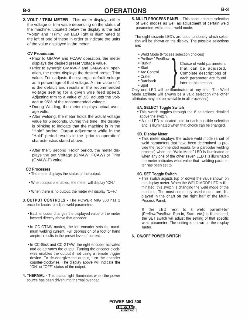
5. MULTI-PROCESS PANEL - This panel enables selectionof weld modes as well as adjustment of certain weldparameters within each weld mode.
The eight discrete LED’s are used to identify which selec-tion will be shown on the display. The possible selectionsare:
• Weld Mode (Process selection choices)• Preflow / Postflow• Run-In• Start• Arc Control• Crater• Burnback• Spot
Only one LED will be illuminated at any time. The WeldMode attribute will always be a valid selection (the otherattributes may not be available in all processes).
5A. SELECT Toggle Switch• This switch toggles through the 8 selections detailed
above the switch.• A red LED is located next to each possible selection
and is illuminated when that choice can be changed.
5B. Display Meter• This meter displays the active weld mode (a set of
weld parameters that have been determined to pro-vide the recommended results for a particular weldingprocess) when the “Weld Mode” LED is illuminated orwhen any one of the other seven LED’s is illuminatedthe meter indicates what value that welding parame-ter has been set to.
5C. SET Toggle Switch• This switch adjusts (up or down) the value shown on
the display meter. When the WELD MODE LED is illu-minated, this switch is changing the weld mode of themachine. The most commonly used modes are dis-played in the chart on the right half of the Multi-Process Panel.
If the LED next to a weld parameter(Preflow/Postflow, Run-In, Start, etc.) is illuminated,the SET switch will adjust the setting of that specificweld parameter. The setting is shown on the displaymeter.
6. ON/OFF POWER SWITCH
B-3B-3 OPERATIONS
POWER MIG 300
} Choice of weld parametersthat can be adjusted.Complete descriptions ofeach parameter are foundlater in this section.
2. VOLT / TRIM METER - This meter displays eitherthe voltage or trim value depending on the status ofthe machine. Located below the display is the text"Volts" and "Trim." An LED light is illuminated tothe left of one of these in order to indicate the unitsof the value displayed in the meter.
CV Processes• Prior to GMAW and FCAW operation, the meter
displays the desired preset Voltage value. • Prior to synergic GMAW-P and GMAW-PP oper-
ation, the meter displays the desired preset Trimvalue. Trim adjusts the synergic default voltageas a percentage of that voltage. A trim value of 1is the default and results in the recommendedvoltage setting for a given wire feed speed.Adjusting trim to a value of .95, adjusts the volt-age to 95% of the recommended voltage.
• During Welding, the meter displays actual aver-age volts.
• After welding, the meter holds the actual voltagevalue for 5 seconds. During this time , the displayis blinking to indicate that the machine is in the"Hold" period. Output adjustment while in the"Hold" period results in the "prior to operation"characteristics stated above.
• After the 5 second "Hold" period, the meter dis-plays the set Voltage (GMAW, FCAW) or Trim(GMAW-P) value.
CC Processes• The meter displays the status of the output.
• When output is enabled, the meter will display "ON."
• When there is no output, the meter will display "OFF."
3. OUTPUT CONTROLS - The POWER MIG 300 has 2encoder knobs to adjust weld parameters.
• Each encoder changes the displayed value of the meterlocated directly above that encoder.
• In CC-GTAW modes, the left encoder sets the maxi-mum welding current. Full depression of a foot or handamptrol results in the preset level of current.
• In CC-Stick and CC-GTAW, the right encoder activatesand de-activates the output. Turning the encoder clock-wise enables the output if not using a remote triggerdevice. To de-energize the output, turn the encodercounter-clockwise. The display above will indicate the"ON" or "OFF" status of the output.
4. THERMAL - This status light illuminates when the powersource has been driven into thermal overload.

B-4 B-4OPERATION
POWER MIG 300
SETTING AND CONFIGURING THE POWERMIG 300 FOR WELDING
• Check that the electrode polarity is correct for the processand turn the Power Switch to the "ON" position. After the"boot-up" period (approximately 20 seconds), the POWERMIG 300 will default to the last preset weld mode that wasactive when the machine was powered down. The Multi-Process Panel defaults with the "Weld Mode" active.
• Toggle the SET switch to the desired "Weld Mode" opera-tion. The Multi-Process Meter displays a weld mode num-ber corresponding to a CC or CV welding process asdetailed by the chart on the right side of the panel. In theexample shown in Figure B.2 “3” is displayed above theSET switch. This means that the machine is set for CC-GTAW (TIG) welding.
• Toggle the SELECT switch to activate the "weld parame-ters" for the selected weld mode.
• Set each parameter using the SET switch to adjust theparameter displayed on the display meter.
NOTE: If the LED next to the weld parameter is flashing, theWFS/AMP and/or the Volt/Trim values can also be adjustedfor that parameter using the control knobs below each dis-play meter. An LED below each of the displays will also beflashing to indicate which value is adjustable.
The Table B.1 shows which weld parameters are adjustablefor a given weld mode. The weld parameters are detailedlater in this section.
PREFLOW / RUN IN START ARC CONTROL CRATER BURNBACK SPOTPOSTFLOW
CC-STICK ----- ----- Yes Yes ----- ----- -----CC-GTAW Yes ----- Yes ----- ----- ----- -----CV-FCAW ----- Yes Yes Yes Yes Yes YesCV-GMAW Yes Yes Yes Yes Yes Yes YesCV-GMAW-P Yes Yes Yes Yes Yes Yes YesPOWER Yes Yes Yes Yes Yes Yes Yes
3
FIGURE B.2
TABLE B.1

B-5 B-5OPERATION
POWER MIG 300
MULTI-PROCESS PANEL FUNCTIONS
Weld ModeSetting the Weld Mode is selecting the proper programfrom the ones available in the machine’s memory for aparticular welding application. The table on the right sideof the front panel (See Figure B.2) gives information onthe different programs available in this machine. Itdescribes the type of process (CV, CC, synergicGMAW), type of metal (mild steel, stainless steel, alu-minum), type of shielding gas and size of electrode rec-ommended for a particular mode.
The Weld Mode selection is enabled by toggling theSELECT switch until the LED next to Weld Mode is lit. AWeld Mode number will be displayed on the displaymeter. Toggling the SET switch up or down will increaseor decrease the WELD MODE number displayed. Themachine will change to the selected weld mode after twoseconds of SET switch inactivity. If the SELECT switch ischanged before two seconds of SET switch inactivity, themachine will not change modes. The last active WeldMode will be saved at power down so that it will beselected with the next power up of the machine.
Preflow / Postflow• The Preflow setting allows a time to be selected for
shielding gas to flow after the trigger is pulled and priorto wire feeding and establishing an arc.
• The Postflow setting allows a time to be selected forshielding gas to continue to flow after the trigger isreleased and output current is turned off.
• The Preflow timer will be selected by toggling theSELECT switch until the LED next to PREFLOW/POSTFLOW is lit. The display meter will read Pre. Thepresent Preflow time will be displayed and can bechanged by positioning the SET switch up or down.
• The Postflow timer will be selected by pressing downthe SELECT switch an additional time. The LED nextto PREFLOW / POSTFLOW will remain lit; but the dis-play meter will now read Pos. The present Postflowtime will be displayed and can be changed by position-ing the SET switch up or down.
• The default value for both Preflow and Postflow is"OFF" (0 seconds).
• Preflow can be adjusted from 0 to 2.5 seconds in 0.1second increments.
• Postflow can be adjusted from 0 to 10.0 seconds in 0.1second increments.
Run-In• The Run-In function offers the ability to set a wire feed
speed, from trigger until an arc is established, that is inde-pendent of the Welding or Start wire feed speed. Setting aRun-In WFS lower than the welding WFS avoids stubbingproblems when starting the arc.
• Run-In is selected by toggling the SELECT switch until theLED next to RUN-IN is lit. A Run-In WFS may be adjustedusing the SET switch on the Multi-Process Panel. TheDisplay meter on the Multi-Process Panel will indicate therun-in speed. Do not use the Output Control Knob on theupper case front to adjust the WFS. This will change thewelding WFS displayed in the meters on the upper casefront.
• The default value for Run-In is "OFF."
• Run-In speed is adjustable from 50 ipm to 150 ipm(Inches per Minute).
Start ProcedureThis machine provides the option of setting a StartingProcedure to start the weld, and from there, to ramp to thewelding procedure over a specified amount of time.Typically starting on a higher starting procedure than thewelding procedure is known as a “Hot Start”. Setting a start-ing procedure lower than the welding procedure is known asa “Cold Start”.
For SMAW (Stick) welding setting a “Hot Start” helps tominimize stubbing the electrode.
For GTAW (TIG) welding setting a “Cold Start” minimizesburn-through of thin materials when not using a manualamperage control.
For Wire Feed welding using a start procedure can helpimprove starting characteristics. A good example is whenwelding aluminum. Aluminum’s high thermal conductivityresults in heat spreading around the plate very fast.Therefore more energy is necessary at the very beginning toheat up the starting point of the weld. Once the weldingbegins, it is not necessary to give this extra heat anymoreso a ramp down to the welding procedure is necessary.
To set a Start Procedure begin by using the SELECT switchto select the Start LED. Using the SET switch, enter thedesired Start ramp time duration (its available values rangefrom 0.01 seconds to 0.50 seconds in increments of 0.01seconds or the default value of OFF). This value will be dis-played on the digital meter of the multiprocess panel (SeeFigure B.2).
After setting the Start time also set the WFS, andvoltage/trim. The way to know what information needsto be entered is to look for flashing LED’s. If an LED isflashing that parameter value needs to be entered.

B-6 B-6OPERATION
POWER MIG 300
Arc Control (See Table B.2)There are no specific unit values offered because the settingof this feature largely depends upon operator preference.Arc Control has a different effect on the character of the arcdepending upon the welding process applied.
In SMAW (STICK mode), arc control adjusts the arc force. Itcan be set to the lower range for a soft and less penetratingarc characteristic (negative numeric values) or to the higherrange (positive numeric values) for a crisp and more pene-trating arc. Normally, when welding with cellulosic types ofelectrodes (E6010, E7010, E6011), a higher energy arc isrequired to maintain arc stability. This is usually indicatedwhen the electrode sticks to the work-piece or when the arcpops-out during manipulative technique. For low hydrogentypes of electrodes (E7018, E8018, E9018, etc.) a softer arcis usually desirable and the lower end of the Arc Controlsuits these types of electrodes. In either case the arc con-trol is available to increase or decrease the energy leveldelivered to the arc.
In GMAW-S, the short-circuiting mode of metal transfer, theArc Control features the ability to increase or decrease theenergy level at the arc. Setting the arc control from 1 to 10decreases energy, and setting the Arc Control from 0 to –10increases the energy delivered to the arc.
Solid carbon steel electrodes in a range from .025"- .045" (.6mm – 1.1 mm) are nominally used, and the shielding gasblend for GMAW-S is usually 100% carbon dioxide or ablend of argon and carbon dioxide. The Arc Control in thisscenario is set to control the droplet size and more pinch isadded (increasing pinch reduces energy to the arc) toachieve the "bacon frying" sound associated with this modeof metal transfer.
Carbon steel electrodes employed in GMAW-S usually per-form best when the droplet size is regulated by pinch toreduce the droplet size transferred with each short-circuitevent.
When welding with solid stainless steel types of electrodes itis usually desirable to increase the energy delivered to thearc. High percentage argon blends with a 2 % addition ofoxygen or a three part shielding gas blend comprised of90% Helium + 7.5% Argon + 2.5 % carbon dioxide are usu-ally employed. The added energy is associated, in this sce-nario, with increasing the inductance (negative numeric val-ues). By adding to the energy level the weld bead appear-ance improves – spatter levels decrease and wetting actionat the toes of a fillet weld increases. The arc is softer withthe higher inductance setting and the arc lends itself tofaster travel speed.
In GMAW-P, the pulsed spray mode of metal transfer, theArc Control is, once again, used to increase and decreasethe focus of the energy delivered to the arc. Increasing thesetting in the range of +1 to +10 results in an increase inpulsed frequency, and the effect is to narrow the arc coneand concentrate the available energy to a smaller area.Decreasing the Arc Control setting from –1 to –10 results ina reduction of pulsed frequency – the result is a broader arccone, which creates a wider weld bead.
Important to note here is that if a component of a pulsedwaveform is increased, then another must be decreased.Adding pulsed frequency through an increase in the ArcControl setting, then also results in a proportional decreasein background current. If this were not the case, then the arcwould become too long, with too much energy, and the arcwould be unusable.
PROCESS ARC SETTING APPLICATION ANDCONTROL RESULTSYNONYM
SMAW (STICK) Arc Force Lower (-1 to -10) for Minus settings are softlow hydrogen types of and buttery for low electrodes. Higher (+1 hydrogen electrodes.to +10) for cellulosic Plus settings are harshand other types. and digging for other
types of electrodes.GMAW – S (Short Inductance or Setting -1 to -10 for The minus settingscircuiting metal Pinch Control softer higher energy result a more fluid transfer arc. Setting +1 to +10 puddle and larger
for a crisper lower droplet size. The lowerenergy arc. settings reduce the
droplet size and reduceenergy to the arc.
GMAW – P (Pulsed Pulsed frequency Minus settings reduces Wider arc cone andspray metal transfer) control frequency. Plus weld bead. Narrower
settings increase arc cone and narrowerfrequency. weld bead.
Pulse – on –Pulse™ Pulsed frequency Minus settings result in Minus settings result in(Aluminum Only) array control lower array frequency a wider bead with more
and the plus settings distinct ripples. Plusincrease the array settings narrow thefrequency. resultant bead and the
ripples are less distinct.
TABLE B.2-Arc control settings by process

B-7 B-7OPERATION
POWER MIG 300
In the case of special waveforms designed for pulsed weld-ing aluminum, Pulse on Pulse™, the effect is similar to whatoccurs with standard pulse. As the Arc Control is increasedfrom +1 to +10 the frequency of the Pulse on Pulse arrayincreases. As the frequency increases the weld bead ripplesbecome less distinct and the arc cone narrows. When theArc Control is set from -1 to -10 the Pulse on Pulse arraysdecrease in frequency, the weld bead ripples become moredistinct, and the bead width increases.
In GMAW-PP mode, arc control adjusts the modulation fre-quency, which means the speed at which the ripples areproduced in the weld. (See Pulse-on-pulse description laterin this section.) When faster travel speeds are desired, arccontrol needs to be set higher. When slower travel speedsare desired, arc control needs to be set lower.
• The Arc-control adjustment is selected by toggling theSELECT switch until the LED next to ARC CONTROL islit. The Arc-control value will be displayed. Arc-control canbe adjusted by toggling the SET switch up or down.
• The default value is "OFF."
CraterThe crater is the end of the weld, which normally solidifiescreating a concave surface. This can result in stresses thatcan cause cracks in the center of the crater. The purpose ofthe Crater control is to fill up the crater, so that its surfacebecomes flat.
Crater control in this machine is more efficient than in othermachines. Normally, in other machines, the crater filling pro-cedure is a step down from the welding WFS to the craterfilling WFS. In this machine instead of a step down, the tran-sition is a ramp down, which results in a more controlled fill-ing up of the crater and so, less stresses present in it.
The values to enter are first the desired time to stay at theCrater settings and the desired WFS and voltage/trim to fillthe crater.
• The Crater timer is selected by toggling the SELECTswitch until the LED next to CRATER is lit and flashing. Acrater time may be set using the SET switch.
• The available values for crater control time go from "Off"to 0.1 seconds and from there to 10.0 seconds in incre-ments of 0.1 seconds.
• The Crater function offers the ability to set an endpoint forWFS and Voltage that will be reached over a specifiedtime period. At the end of the weld when the trigger isreleased, the crater timer will begin and the WFS andVolts settings will ramp down from the Weld Mode WFSand Voltage settings to the Crater WFS and Voltage set-tings over the time selected. This creates a ramp down ofthe WFS and Volts during the Crater time.
• In the GMAW, FCAW, and Power weld modes, craterWFS and voltage are adjustable using the control knobson the upper case front. This in indicated by the flashingLED’s next to "WFS" and "VOLTS."
• In the GMAW-P weld modes, Crater WFS and trim areadjustable. This is indicated by the flashing LEDs next to"WFS" and "TRIM."
BurnbackSetting the Burnback means setting the adjustable timedelay between turning off the wire feeding and turning offthe arc. Burnback helps to prevent wire sticking to the pud-dle.
• The Burnback feature will allow current to continue to flowfor a specified time period at the end of a weld after wirefeeding has stopped.
• The Burnback timer will be selected by toggling theSELECT switch until the LED next to BURNBACK is lit. Aburnback time may be set using the SET switch.
• The default value is "OFF" (0 seconds).
• Burnback time is adjustable from 0 to 0.25 seconds in0.01 second increments.
SpotThe Spot Timer adjusts arc on-time for spot or tack welds.
• With the Spot feature active (Spot time selected), whenthe trigger is pulled and the arc is established, the weldwill continue until the expiration of the spot timer and thenext active state will be enabled (crater or burnback). Thetrigger must be released and pulled again for another Spotcycle.
• The Spot timer is selected by toggling the SELECT switchuntil the LED next to SPOT is lit. The present SPOT timewill be displayed and can be changed by toggling the SETswitch up or down.
• The default value is "OFF" (0 seconds).
• Spot can be adjusted from 0 to 10.0 seconds in 0.1 sec-ond increments.
WIRE DRIVE ROLL
The drive rolls installed with the POWER MIG 300 have twogrooves, one side for .030" (0.8mm) solid steel electrode,and the other for the .045”(1.2mm) electrode. The actualdrive roll size is stenciled on the side opposite of its groove.If feeding problems occur, a check may be required to makesure that the wire size and the drive roll size matches. See"Procedure for Changing Drive Rolls" in this section.

B-8 B-8OPERATION
POWER MIG 300
5. Rotate the spindle and adapter so the retainingspring is at the 12 o'clock position.
6. Position the Readi-Reel so that it will rotate in a direc-tion when feeding so as to be de-reeled from top theof the coil.
7. Set one of the Readi-Reel inside cage wires on theslot in the retaining spring tab.
8. Lower the Readi-Reel to depress the retaining springand align the other inside cage wires with the groovesin the molded adapter.
9. Slide cage all the way onto the adapter until theretaining spring "pops up" fully.
Check to be sure the retaining ring has fully returned to the lockingposition and has securely locked the Readi-Reel cage in place.Retaining spring must rest on the cage, not the welding electrode.-----------------------------------------------------------------------------------------------10. To remove Readi-Reel from Adapter, depress retain-
ing spring tab with thumb while pulling the Readi-Reel cage from the molded adapter with both hands.Do not remove adapter from spindle.
FIGURE B.4
TO MOUNT 10 to 44 Lb. (4.5-20 kg) SPOOLS (12"/300mm Diameter) or 14Lb.(6 Kg) Innershield Coils:
(For 13-14 lb. (6 Kg) Innershield coils, a K435 CoilAdapter must be used).
1. Open the Wire Drive Compartment Door
2. Depress the Release Bar on the Retaining Collarand remove it from the spindle.
3. Place the spool on the spindle making certain thespindle brake pin enters one of the holes in theback side of the spool (Note: an arrow mark on thespindle lines up with the brake holding pin to assistin lining up a hole). Be certain the wire comes offthe reel in a direction so as to de-reel from the topof the coil.
CAUTION
PROCEDURE FOR CHANGINGDRIVE AND IDLE ROLL SETS1. Turn off the power source.
2. Release the pressure on the idle roll by swingingthe adjustable pressure arm down toward the backof the machine. Lift the cast idle roll assembly andallow it to sit in an upright position.
3. Remove the outside wire guide retaining plate byloosening the two large knurled screws.
4. Twist the drive roll retaining mechanism to theunlocked position as shown below and remove thedrive roll. (See Figure B.3)
5. Remove the inside wire guide plate.
6. Replace the drive and idle rolls and inside wireguide with a set marked for the new wire size.NOTE: Be sure that the gun liner and contact tipare also sized to match the selected wire size.
7. Manually feed the wire from the wire reel, over thedrive roll groove and through the wire guide andthen into the brass bushing of the gun and cableassembly.
8. Replace the outside wire guide retaining plate bytightening the two large knurled screws. Repositionthe adjustable pressure arm to its original positionto apply pressure. Adjust pressure as necessary.
WIRE REEL LOADING - READI-REELS,SPOOLS OR COILS To Mount a 30 Lb. (14 kg) Readi-Reel Package(Using the Molded Plastic K363-P Readi-ReelAdapter):
1. Open the Wire Drive Compartment Door
2. Depress the Release Bar on the Retaining Collarand remove it from the spindle.
3. Place the Optional Adapter on the spindle
4. Re-install the Retaining Collar. Make sure that theRelease Bar “pops up” and that the collar retainersfully engage the retaining ring groove on the spin-dle.
LOCKED POSITIONUNLOCKED POSITION
FIGURE B.3

B-9B-9 OPERATION
POWER MIG 300
4. Re-install the Retaining Collar. Make sure that theRelease Bar “pops up” and that the collar retainersfully engage the retaining ring groove on the spin-dle.
FEEDING WIRE ELECTRODE
When triggered, the electrode and drive mecha-nism are electrically “hot” relative to work andground and remain “hot” several seconds afterthe gun trigger is released.------------------------------------------------------------------------
NOTE: Check that drive rolls, guide plates and gunparts are proper for the wire size and type being used.Refer to Table C.1 in ACCESSORIES section.
1. Turn the Readi-Reel or spool until the free end ofthe electrode is accessible.
2. While securely holding the electrode, cut off thebent end and straighten the first six inches. (If theelectrode is not properly straightened, it may notfeed properly through the wire drive system).
3. Release the pressure on the idle roll by swingingthe adjustable pressure arm down toward the backof the machine. Lift the cast idle roll assembly andallow it to sit in an upright position. Leave the outerwire guide plate installed. Manually feed the wirethrough the incoming guide bushing and throughthe guide plates (over the drive roll groove). Push asufficient wire length to assure that the wire has fedinto the gun and cable assembly without restriction.Reposition the adjustable pressure arm to its origi-nal position to apply pressure to the wire.
4. Press gun trigger to feed the electrode wire throughthe gun.
IDLE ROLL PRESSURE SETTING
The idle roll pressure adjustment knob is set at thefactory at the #2 hash mark. This is an approximatesetting. The optimum idle roll pressure varies withtype of wire, wire diameter, surface conditions, lubri-cation, and hardness. As a general rule, hard wiresmay require greater pressure, and soft, or aluminumwire, may require less pressure than the factory set-ting. The optimum idle roll setting can be determinedas follows:
1. Press end of gun against a solid object that is elec-trically isolated from the welder output and pressthe gun trigger for several seconds.
2. If the wire “birdnests”, jams or breaks at the driveroll, the idle roll pressure is too great. Back theadjustment knob out 1/2 turn, run new wire throughgun, and repeat above steps.
3. If the only result was drive roll slippage, loosen theadjustment knob on the conductor plate and pullthe gun cable forward about 6" (15 cm). Thereshould be a slight waviness in the expose wire. Ifthere is not waviness, the pressure is too low.Tighten the adjustment knob 1/4 turn, reinstall thegun cable and repeat the above steps.
AVOIDING WIRE FEEDING PROBLEMS
Wire feeding problems can be avoided by observingthe following gun handling procedures:
a. Do not kink or pull cable around sharp corners.
b. Keep the gun cable as straight as possible whenwelding or loading electrode through cable.
c. Do not allow dolly wheels or trucks to run overcables.
d. Keep cable clean by following maintenance instruc-tions.
e. Use only clean, rust-free electrode. Lincoln elec-trodes have proper surface lubrication.
f. Replace the contact tip when the arc starts tobecome unstable or the contact tip end is fused ordeformed.
g. Keep wire reel spindle brake tension to the mini-mum required to prevent excess reel over-travelwhich may cause wire “loop-offs” from the coil.
h. Use proper drive rolls and wire drive/idle roll pres-sure for wire size and type being used.
WARNING
B-10 B-10OPERATION
POWER MIG 300
SPECIAL WELDING PROCESSESAVAILABLE ON THE POWER MIG 300
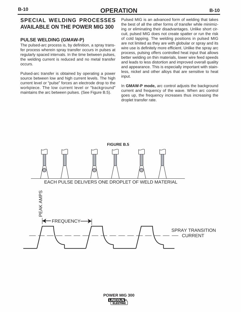
PULSE WELDING (GMAW-P)The pulsed-arc process is, by definition, a spray trans-fer process wherein spray transfer occurs in pulses atregularly spaced intervals. In the time between pulses,the welding current is reduced and no metal transferoccurs.
Pulsed-arc transfer is obtained by operating a powersource between low and high current levels. The highcurrent level or “pulse” forces an electrode drop to theworkpiece. The low current level or “background”maintains the arc between pulses. (See Figure B.5).
FIGURE B.5
PE
AK
AM
PS
FREQUENCY
SPRAY TRANSITIONCURRENT
EACH PULSE DELIVERS ONE DROPLET OF WELD MATERIAL
Pulsed MIG is an advanced form of welding that takesthe best of all the other forms of transfer while minimiz-ing or eliminating their disadvantages. Unlike short cir-cuit, pulsed MIG does not create spatter or run the riskof cold lapping. The welding positions in pulsed MIGare not limited as they are with globular or spray and itswire use is definitely more efficient. Unlike the spray arcprocess, pulsing offers controlled heat input that allowsbetter welding on thin materials, lower wire feed speedsand leads to less distortion and improved overall qualityand appearance. This is especially important with stain-less, nickel and other alloys that are sensitive to heatinput.
In GMAW-P mode, arc control adjusts the backgroundcurrent and frequency of the wave. When arc controlgoes up, the frequency increases thus increasing thedroplet transfer rate.
B-11 B-11 OPERATION
POWER MIG 300
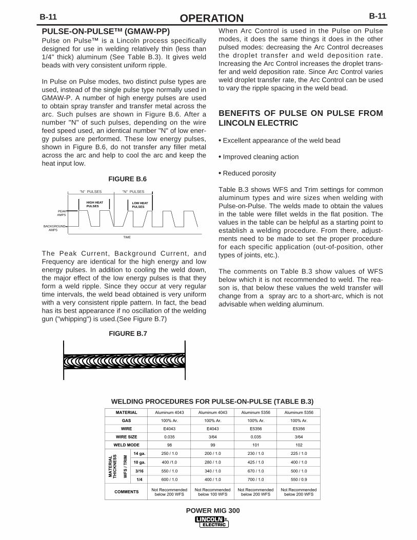
PULSE-ON-PULSE™ (GMAW-PP)Pulse on Pulse™ is a Lincoln process specificallydesigned for use in welding relatively thin (less than1/4" thick) aluminum (See Table B.3). It gives weldbeads with very consistent uniform ripple.
In Pulse on Pulse modes, two distinct pulse types areused, instead of the single pulse type normally used inGMAW-P. A number of high energy pulses are usedto obtain spray transfer and transfer metal across thearc. Such pulses are shown in Figure B.6. After anumber "N" of such pulses, depending on the wirefeed speed used, an identical number "N" of low ener-gy pulses are performed. These low energy pulses,shown in Figure B.6, do not transfer any filler metalacross the arc and help to cool the arc and keep theheat input low.
The Peak Current, Background Current, andFrequency are identical for the high energy and lowenergy pulses. In addition to cooling the weld down,the major effect of the low energy pulses is that theyform a weld ripple. Since they occur at very regulartime intervals, the weld bead obtained is very uniformwith a very consistent ripple pattern. In fact, the beadhas its best appearance if no oscillation of the weldinggun ("whipping") is used.(See Figure B.7)
When Arc Control is used in the Pulse on Pulsemodes, it does the same things it does in the otherpulsed modes: decreasing the Arc Control decreasesthe droplet transfer and weld deposit ion rate.Increasing the Arc Control increases the droplet trans-fer and weld deposition rate. Since Arc Control variesweld droplet transfer rate, the Arc Control can be usedto vary the ripple spacing in the weld bead.
BENEFITS OF PULSE ON PULSE FROMLINCOLN ELECTRIC
• Excellent appearance of the weld bead
• Improved cleaning action
• Reduced porosity
Table B.3 shows WFS and Trim settings for commonaluminum types and wire sizes when welding withPulse-on-Pulse. The welds made to obtain the valuesin the table were fillet welds in the flat position. Thevalues in the table can be helpful as a starting point toestablish a welding procedure. From there, adjust-ments need to be made to set the proper procedurefor each specific application (out-of-position, othertypes of joints, etc.).
The comments on Table B.3 show values of WFSbelow which it is not recommended to weld. The rea-son is, that below these values the weld transfer willchange from a spray arc to a short-arc, which is notadvisable when welding aluminum.
PEAK AMPS
BACKGROUND AMPS
TIME
HIGH HEATPULSES
LOW HEATPULSES
"N" PULSES "N" PULSES
FIGURE B.6
FIGURE B.7
Aluminum 4043 Aluminum 4043 Aluminum 5356 Aluminum 5356
100% Ar. 100% Ar. 100% Ar. 100% Ar.
E4043 E4043 E5356 E5356
0.035 3/64 0.035 3/64
98 99 101 102
14 ga. 250 / 1.0 200 / 1.0 230 / 1.0 225 / 1.0
10 ga. 400 /1.0 280 / 1.0 425 / 1.0 400 / 1.0
3/16 550 / 1.0 340 / 1.0 670 / 1.0 500 / 1.0
1/4 600 / 1.0 400 / 1.0 700 / 1.0 550 / 0.9
WF
S /
TR
IM
MA
TE
RIA
L
TH
ICK
NE
SS
MATERIAL
GAS
WIRE
WIRE SIZE
WELD MODE
Not Recommended below 200 WFSCOMMENTS Not Recommended
below 200 WFSNot Recommended
below 100 WFSNot Recommended
below 200 WFS
WELDING PROCEDURES FOR PULSE-ON-PULSE (TABLE B.3)

B-12B-12 OPERATION
POWER MIG 300
POWER MODE™The Power Mode™ process was developed byLincoln to maintain a stable and smooth arc at lowprocedure settings which are needed to weld thinmetal without pop-outs or burning-through. ForAluminum welding, it provides excellent control andthe ability to maintain constant arc length. This resultsin improved welding performance in two primary typesof applications.
• Short Arc MIG at low procedure settings.
• Aluminum MIG welding.
Power Mode™ is a method of high speed regulationof the output power whenever an arc is established. Itprovides a fast response to changes in the arc. Thehigher the Power Mode Setting, the longer the arc. If awelding procedure is not established, the best way todetermine the Power Mode Setting is by experimenta-tion until the desired output result is established.
In the Power Mode two variables need to be set:
• Wire Feed Speed
• Power Mode Trim
Setting up a Power Mode procedure is similar to set-ting a CV MIG procedure. Select a shielding gasappropriate for a short arc process.
• For steel, use 75/25 Ar/CO2 shield gas.
• For Stainless, select a Helium blend Tri-Mix.
• For Aluminum, use 100% Ar.
Start by setting the wire feed speed based upon mate-rial thickness and appropriate travel speed. Thenadjust the Volts/Trim knob as follows:
• For steel, listen for the traditional “frying egg”sound of a good short-arc MIG procedure to knowyou have the process set correctly.
• For aluminum, simply adjust the Volts/Trim knobuntil the desired arc length is obtained.
Note the Volts/Trim display is simply a relative numberand DOES NOT correspond to voltage.
Some procedure recommendations appear in TableB.4.
Aluminum 4043 Aluminum 5356 Mild Steel Mild Steel Mild Steel Mild Steel Mild Steel Mild Steel Stainless Steel Stainless Steel
E4043 E5356 L56 L56 L56 L56 L56 L56 E308L E308L
0.035 0.035 0.025 0.025 0.030 0.030 0.035 0.035 0.030 0.035
100% Ar. 100% Ar. 100% CO2 75/25 Ar/CO2 100% CO2 75/25 Ar/CO2 100% CO2 75/25 Ar/CO2 Tri-mix Tri-mix
22 ga. Not Recommended 100 / 0.8 Not Recommended 90 / 1.0
20 ga. 120 / 1.0 120 / 1.0 100 / 0.7 100 /1.0 80 / 1.5 50 / 0.5
18 ga. 140 / 1.7 140 / 1.5 110 / 1.5 110 / 1.5 100 / 2.5 100 / 2.5 110 / 2.0 110 / 2.0
16 ga. 190 / 2.0 190 / 2.0 125 / 2.0 125 / 2.0 125 / 3.0 125 / 3.0 140 / 2.5 130 / 2.7
14 ga. 400 / 2.0 400 / 2.5 260 / 3.0 260 / 3.0 160 / 2.3 160 / 2.3 160 / 3.8 160 / 3.5 210 / 3.0 190 / 3.5
12 ga. 330 / 5.0 330 / 4.5 230 / 3.5 230 / 3.5 200 / 5.0 200 / 4.5 270 / 5.0 230 / 6.0
10 ga. 500 / 7.0 500 / 7.0 300 / 6.0 300 / 6.0 240 / 6.5 240 / 7.0 325 / 6.5 300 / 7.0
3/16 570 / 9.0 600 / 7.8 400 / 7.5 400 / 7.0
1/4 700 / 9.1 700 / 8.5
MA
TE
RIA
L T
HIC
KN
ES
S
WF
S /
PO
WE
R M
OD
E S
ET
TIN
G
COMMENTS
Not Recommended
below 400 WFS
MATERIAL
WIRE
WIRE SIZE
GAS
Not Recommended
below 400 WFS
Recommended Welding Procedures for Power Mode - Table B.4

C-1 C-1ACCESSORIES
DRIVE ROLL KITS
Refer to Table C.1 for various drive roll kits that areavailable for the POWER MIG. All items in Bold aresupplied standard with the POWER MIG.
TABLE C.1
*.035 Aluminum recommended for Push-Pull systems only.
3/64" (1.2 mm) ALUMINUM FEEDING KIT (K2153-1)This kit helps push feeding aluminum through stan-dard machine feeder and gun. It provides gun andwire drive conversion parts to weld with 3/64" (1.2mm) aluminum wire. 5356 alloy aluminum wire is rec-ommended for best push feeding performance.
Kit includes drive rolls and wire guide plate for thewire drive, liner and two contact tips for the gun, alongwith installation instructions.
K363P READI-REEL ADAPTERThe K363P Readi-Reel Adapter mounts to the 2"spindle. It is needed to mount the 22-30 lb. Readi-Reels.
DUAL CYLINDER MOUNTING KIT(K1702-1)Permits stable side-by-side mounting of two full size(9" dia. x 5' high) gas cylinders with “no lift” loading.Simple installation and easy instructions provided.Includes upper and lower cylinder supports, wheelaxles and mounting hardware.
ALTERNATIVE MAGNUM GMAWGUN AND CABLE ASSEMBLIES
The following Magnum 300 gun and cable assembliesare separately available for use with the POWER MIG300. Each is rated 300 amps 60% duty cycle (or 300amps 40% duty) and is equipped with the integratedconnector, twist-lock trigger connector, fixed nozzleand insulator, and includes a liner, diffuser, and con-tact tips for the wire sizes specified:
MAGNUM GUN CONNECTION KIT(Optional K466-6)Using the optional K466-6 Magnum Connection kit forthe POWER MIG permits use of standard Magnum200, 300 or 400 gun and cable assemblies.
K1692-2 SPOOL GUN (PRINCETM XL)When the POWER MIG Gun Selector Switch is in the“Standard / Spool Gun” position, the POWER MIG pro-vides gun trigger switch transfer between the Magnumgun or the spool gun for the same polarity welding withdifferent wire and gas processes.
Closing either gun trigger will cause the electrode ofboth guns to be electrically “HOT”. Be sure unusedgun is positioned so electrode or tip will not contactmetal case or other metal common to work.-----------------------------------------------------------------------Because the control circuitry senses each gun throughits trigger leads, weld parameters are displayed andadjustable for the last gun that was triggered.
1. Pulling the trigger for the built-in feeder gun(Magnum 300):• Disables spool gun operation.• Changes the displays of the POWER MIG 300 to
correspond to feeder gun operation.• Closing feeder gun trigger starts feeder gun weld-
ing and makes both electrodes electrically “HOT”.
2. Pulling SPOOL GUN Trigger:• Disables built-in feeder gun operation.• Changes the displays of the POWER MIG 300 to
correspond to Spool Gun operation.• Closing spool gun trigger starts spool gun welding
and makes both electrodes electrically “HOT”.
3. Operation with POWER MIG 300:• Install the spool gun per the installation instructions• Turn the POWER MIG 300 input power ON.• Make sure that the Gun Selector Switch is in the
“Standard / Spool Gun” position.• Pull and release the trigger of the Spool Gun. The
Power Mig recognizes the spool gun as active and weldparameters are adjustable for welding with the SpoolGun
Wire Size Drive Roll Kit
.023”-.030” (0.6-0.8 mm) KP1696-030SSolid.035” (0.9 mm) KP1696-035SSteel.045” (1.2 mm) KP1696-045S.040” (1.0mm) KP-1696-2
.035-.045” (0.9-0.2mm) KP-1696-1Cored .035” (0.9 mm) KP1697-035C
.045” (1.2 mm) KP1697-045CAluminum 3/64” (1.2 mm) KP1695-3/64A
English Wire Metric WireLength Part No. Size Size
10' (3.0 m) K470-112' (3.6 m) K470-7 .035 – .045" 0.9 – 1.2 mm15' (4.5 m) K470-3
CAUTION
POWER MIG 300

C-2C-2 ACCESSORIESNon-Synergic Weld Modes (Mode 5)
• Voltage is adjustable at the power source. Theright control knob on the power source willadjust the voltage that is displayed in the meterdirectly above it.
• The left Display (WFS / AMPS) on the POWERMIG 300 will have 4 dashes (----) to indicatethat the left control knob on the power source isinactive. Wire Feed Speed is set at the SpoolGun.
• The following procedure settings for Aluminum4043 can be used as initial settings for makingtest welds to determine final settings:Wire Dia. WFS Setting Arc VoltageIn. (mm) Spool Gun Setting
.030" (.8 mm) 270 15V
.035" (.9 mm) 250 16V3/64" (1.2 mm) 240 20V
4. Synergic Weld Modes
The POWER MIG 300 is designed to enable synergicweld modes and synergic pulse processes with thespool gun. The actual wire feed speed (WFS) of thespool gun must be measured and manually set on thePOWER MIG 300 as a work point for the POWERMIG 300 (SPD).
• In synergic modes when the spool gun trigger ispulled, an adjustable value for the SPD workpoint is displayed in the left meter. The lettersSPD are displayed in the right meter.
• The left control knob adjusts the SPD value.The right control knob is inactive.
• Measure the actual WFS, in inches per minute,at the spool gun and set the SPD at thePOWER MIG 300 to match this value. WFS canbe measured by pulling the trigger of the spoolgun and feeding wire for 6 seconds. Measurethe length of wire (in inches) that was fed andmultiply by 10.
• The POWER MIG 300 is now configured andready to weld in the synergic mode.
• Adjustment of the SPD value from the set valuehas the affect of adjusting trim or arc length.
• To increase the arc length; increase the SPDvalue at the POWER MIG 300 to a value higherthan the actual WFS.
Remember; do not change the WFS at the spoolgun.
• To decrease the arc length; decrease the SPDvalue at the POWER MIG 300 to a value lowerthan the actual WFS.
Remember: The dialed in SPD value at the POWERMIG 300 does not control the WFS at the spool gun.Rather, it is adjusting the POWER MIG 300 synergicwork point. Therefore, adjusting the SPD value willnot change your actual WFS at the spool gun.WFS can only be changed at the spool gun.
PUSH-PULL FEEDING CONNECTIONADAPTER KIT (K2154-1)
The push-pull adapter kit provides direct connection ofa Cobra Gold or Prince XL torch to the POWER MIG 300wire feeder welder.
The kit is intended for use with the following CobraGold or Prince XL torches:
Cobra GoldAir Cooled 15’(5m) K1589-1 Water-Cooled 15’(5m) K1590-1Air Cooled 25’(8m) K1589-2 Water-Cooled 25’(8m) K1590-2Air Cooled 50’(15m) K1589-3 Water-Cooled 50’(15m) K1590-3
Prince XLAir Cooled 15’(5m) K1591-1 Water-Cooled 15’(5m) K1592-1Air Cooled 25’(8m) K1591-2 Water-Cooled 25’(8m) K1592-2Air Cooled 50’(15m) K1591-3 Water-Cooled 50’(15m) K1592-3
Remove all input power to the POWER MIG 300before installing the Connection Adapter Kit.------------------------------------------------------------------------
Refer to the Owner’s Manual of the Torch forAmperage and Duty Cycle rating information. Thetorch rating may not match the rating of the powersource.------------------------------------------------------------------------MAKING A WELD WITH THE PRINCE XLOR COBRA GOLD TORCH INSTALLED
• Set the idle roll pressure on the wire drive betweenan indicator reading of 0-2. A recommended startpoint is 1.5.
• Set the Gun Selection toggle switch located insidethe wire drive compartment directly above the push-pull control cable connector to "PUSH-PULL GUN."
• Depending on the weld mode, set the Voltage orTrim at the POWER MIG 300 using the right controlknob located on the upper case front panel.
• The Wire Feed Speed (WFS) is set using the controlknob on the Torch. The left control knob on thePOWER MIG 300 is inactive. The actual WFS being setat the torch is displayed on the POWER MIG 300.
• All weld parameters normally available for the activeweld mode are available during push-pull operation.Refer to the Operation Section of this manual.
WARNING
CAUTION
POWER MIG 300

D-1D-1 MAINTENANCE
CONTACT TIP AND GAS NOZZLEINSTALLATION
a. Choose the correct size contact tip for the elec-trode being used (wire size is stenciled on the sideof the contact tip) and screw it snugly into the gasdiffuser.
b. Be sure the nozzle insulator is fully screwed ontothe gun tube and does not block the gas holes inthe diffuser. (NOTE: Insulator is not required whenusing the optional fixed gas nozzles.)
c. Slip the appropriate gas nozzle onto the nozzleinsulator. Adjustable gas nozzles are available witha .62” (15.9 mm) or .50” (12.7 mm) I.D., and in bothstandard (flush) and recessed design. The propernozzle should be selected based on the weldingapplication. Different length fixed nozzles are alsoavailable to fit 300 and 400 amp gun tubes to alloweither spray or short-circuiting transfer welding.
Choose the gas nozzle as appropriate for theGMAW process to be used. Typically, the contacttip end should be flush to .12” (3.1 mm) extendedfor the short-circuiting transfer process and .12”(3.1 mm) recessed for spray transfer. For theOutershield (FCAW) process, 1/8” (3 mm) recess isrecommended.
GUN TUBES AND NOZZLES
a. Replace worn contact tips as required.
b. Remove spatter from inside of gas nozzle and fromtip after each 10 minutes of arc time or as required.
GUN CABLE CLEANING
To help prevent feeding problems, clean cable linerafter using approximately 300 pounds (136 kg) ofelectrode. Remove the cable from the wire feeder andlay it out straight on the floor. Remove the contact tipfrom the gun. Using an air hose and only partial pres-sure, gently blow out the cable liner from the gas dif-fuser end.
SAFETY PRECAUTIONS
ELECTRIC SHOCK can kill.• Have an electrician install and
service this equipment.
• Turn the input power off at thefuse box before working onequipment
• Do not touch electrically hotparts.
GENERAL MAINTENANCE
In extremely dusty locations, dirt may clog the air pas-sages causing the welder to run hot. Blow dirt out ofthe welder with low-pressure air at regular intervals toeliminate excessive dirt and dust build-up on internalparts.
The fan motors have sealed ball bearings whichrequire no service.
DRIVE ROLLS AND GUIDE PLATES
After every coil of wire, inspect the wire drive mecha-nism. Clean it as necessary by blowing with low pres-sure compressed air. Do not use solvents for cleaningthe idle roll because it may wash the lubricant out ofthe bearing. All drive rolls are stamped with the wiresizes they will feed. If a wire size other than thatstamped on the roll is used, the drive roll must bechanged.
For instructions on replacing or changing drive roll,see “Wire Drive Rolls” in Operation section.
WARNING
POWER MIG 300
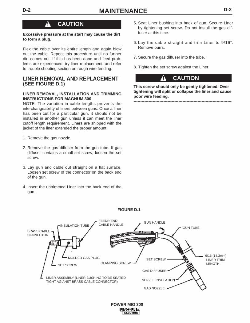
D-2D-2 MAINTENANCE
5. Seat Liner bushing into back of gun. Secure Linerby tightening set screw. Do not install the gas dif-fuser at this time.
6. Lay the cable straight and trim Liner to 9/16”.Remove burrs.
7. Secure the gas diffuser into the tube.
8. Tighten the set screw against the Liner.
This screw should only be gently tightened. Overtightening will split or collapse the liner and causepoor wire feeding.------------------------------------------------------------------------
Excessive pressure at the start may cause the dirtto form a plug.
Flex the cable over its entire length and again blowout the cable. Repeat this procedure until no furtherdirt comes out. If this has been done and feed prob-lems are experienced, try liner replacement, and referto trouble shooting section on rough wire feeding.
LINER REMOVAL AND REPLACEMENT(SEE FIGURE D.1)
LINER REMOVAL, INSTALLATION AND TRIMMINGINSTRUCTIONS FOR MAGNUM 300NOTE: The variation in cable lengths prevents theinterchangeability of liners between guns. Once a linerhas been cut for a particular gun, it should not beinstalled in another gun unless it can meet the linercutoff length requirement. Liners are shipped with thejacket of the liner extended the proper amount.
1. Remove the gas nozzle.
2. Remove the gas diffuser from the gun tube. If gasdiffuser contains a small set screw, loosen the setscrew.
3. Lay gun and cable out straight on a flat surface.Loosen set screw of the connector on the back endof the gun.
4. Insert the untrimmed Liner into the back end of thegun.
CAUTION
CAUTION
GUN HANDLE
SET SCREW
SET SCREW
INSULATION TUBEFEEDR ENDCABLE HANDLE
CLAMPING SCREW
GUN TUBE
9/16 (14.3mm)
GAS DIFFUSER
NOZZLE INSULATION
GAS NOZZLE
MOLDED GAS PLUG
LINER ASSEMBLY (LINER BUSHING TO BE SEATEDTIGHT AGIANST BRASS CABLE CONNECTOR)
BRASS CABLECONNECTOR
LINER TRIMLENGTH
FIGURE D.1
POWER MIG 300

E-1 E-1TROUBLESHOOTING
If for any reason you do not understand the test procedures or are unable to perform the tests/repairs safely, contact yourLocal Lincoln Authorized Field Service Facility for technical troubleshooting assistance before you proceed.
CAUTION
This Troubleshooting Guide is provided to help youlocate and repair possible machine malfunctions.Simply follow the three-step procedure listed below.
Step 1. LOCATE PROBLEM (SYMPTOM).Look under the column labeled “PROBLEM (SYMP-TOMS)”. This column describes possible symptomsthat the machine may exhibit. Find the listing thatbest describes the symptom that the machine isexhibiting.
Step 2. POSSIBLE CAUSE.The second column labeled “POSSIBLE CAUSE” liststhe obvious external possibilities that may contributeto the machine symptom.
Step 3. RECOMMENDED COURSE OF ACTIONThis column provides a course of action for thePossible Cause, generally it states to contact yourlocal Lincoln Authorized Field Service Facility.
If you do not understand or are unable to perform theRecommended Course of Action safely, contact yourlocal Lincoln Authorized Field Service Facility.
Service and Repair should only be performed by Lincoln Electric Factory Trained Personnel.Unauthorized repairs performed on this equipment may result in danger to the technician andmachine operator and will invalidate your factory warranty. For your safety and to avoid ElectricalShock, please observe all safety notes and precautions detailed throughout this manual.
__________________________________________________________________________
WARNING
POWER MIG 300

E-2TROUBLESHOOTINGE-2
If for any reason you do not understand the test procedures or are unable to perform the tests/repairs safely, contact yourLocal Lincoln Authorized Field Service Facility for technical troubleshooting assistance before you proceed.
CAUTION
Observe all Safety Guidelines detailed throughout this manualPROBLEMS
(SYMPTOMS)POSSIBLE AREAS OFMISADJUSTMENT(S)
RECOMMENDEDCOURSE OF ACTION
Major physical or electrical damageis evident when the sheet metalcovers are removed.
Input fuses keep blowing, or inputbreaker keeps tripping
Machine will not power up (No lights)
Machine won’t weld, can’t get anyoutput.
Thermal symbol is lit
1. Contact your local authorizedLincoln Electric Field Servicefacility for technical assistance.
1. Make certain that the fuses orbreakers are properly sized. Seeinstallation section of the manualfor recommended fuse andbreaker sizes.
2. Welding procedure is drawing toomuch output current, or dutycycle is too high. Reduce outputcurrent, duty cycle or both.
3. There is internal damage to thepower source. Contact an autho-rized Lincoln Electric Servicefacility.
1. Make certain that the powerswitch is in the "ON" position.
2. Input voltage selection madeimproperly. Power down, checkinput voltage reconnect accord-ing to diagram on reconnectcover.
1. If the displays show an Err ###see the fault section for correc-tive action.
2. If the displays are not lit refer tomachine will not power up sec-tion.
3. If the thermal symbol is lit refer tothe thermal section.
1. Check for proper fan operation2. Check for material blocking
intake or exhaust louvers.
If all recommended possible areasof misadjustment have beenchecked and the problem persists,Contact your local LincolnAuthorized Field Service Facility.
POWER MIG 300

POWER MIG 300
E-3E-3 TROUBLESHOOTINGObserve Safety Guideline detailed in the beginning of this manual.
PROBLEMS(SYMPTOMS)
Output voltage and wire feed is pre-sent when gun trigger is not pulled(not activated).
Machine output is low. Welds are“cold”, weld bead is rounded orbumped up demonstrating poor wet-ting into plate.
Poor arc striking with electrodesticking or blasting off.
POSSIBLE AREAS OFMISADJUSTMENT(S)
1. Check Weld Mode to make surethe unit is in a CV Mode And nota CC Mode.
2. Remove gun assembly frommachine. If problem is solvedgun assembly is faulty. Repair orreplace.
3. If problem persists when gunassembly is removed frommachine then the problem iswithin the POWER MIG 300.
1. Check input voltage. Make sureinput voltage matches name-plate rating and reconnect panelconfiguration.
2. Make sure settings for wire feedspeed and voltage are correctfor process being used.
3. Make sure output polarity is cor-rect for process being used.
4. Check welding cables and gunassembly for loose or faulty con-nections.
1. Make sure settings for wire feedspeed and voltage are correctfor process being used.
2. The Run-In (Fast or Slow) speedmay be wrong for process andtechnique being used. SeeOperation Section.
3. The gas shielding may beimproper for process being used.
RECOMMENDEDCOURSE OF ACTION
If all recommended possible areasof misadjustment have beenchecked and the problem persists,Contact your local LincolnAuthorized Field Service Facility.
OUTPUT PROBLEMS
If for any reason you do not understand the test procedures or are unable to perform the tests/repairs safely, contact yourLOCAL AUTHORIZED LINCOLN ELECTRIC FIELD SERVICE FACILITY for assistance before you proceed.
CAUTION

POWER MIG 300
E-4E-4 TROUBLESHOOTINGObserve Safety Guidelines detailed in the beginning of this manual.
If for any reason you do not understand the test procedures or are unable to perform the tests/repairs safely, contact yourLOCAL AUTHORIZED LINCOLN ELECTRIC FIELD SERVICE FACILITY for assistance before you proceed.
CAUTION
PROBLEMS(SYMPTOMS)
Rough wire feeding or wire will notfeed but drive rolls are turning.
The wire feed stops while welding.When trigger is released and pulledagain the wire feed starts.
POSSIBLE AREAS OFMISADJUSTMENT(S)
1. The gun cable may be kinked or twisted.2. The wire may be jammed in the gun
cable, or gun cable may be dirty.3. Check drive roll tension and
position of grooves.4. Check for worn or loose drive rolls.5. The electrode may be rusty or dirty.6. Check for damaged or incorrect
contact tip.7. Check wire spindle for ease of
rotation and adjust break ten-sion knob if necessary.
1. Check the wire feed drive rollsand motor for smooth operation.
2. Check for restrictions in the wirefeed path. Check the gun andcable for restrictions.
3. Make sure gun liner and tip arecorrect for wire size being used.
4. Make sure drive rolls and guide platesare clean and are the correct size.
5. Check spindle for ease of rotation.
RECOMMENDEDCOURSE OF ACTION
If all recommended possible areasof misadjustment have beenchecked and the problem persists,Contact your local LincolnAuthorized Field Service Facility.
FEEDING PROBLEMS

POWER MIG 300
E-5E-5 TROUBLESHOOTING
PROBLEMS(SYMPTOMS)
Gas does not flow when gun triggeris pulled.
POSSIBLE AREAS OFMISADJUSTMENT(S)
1. Make sure gas supply is con-nected properly and turned “on”.
2. If the gas solenoid does actuate(click) when the gun trigger ispulled there may be a restrictionin the gas supply line.
3. The gun cable assembly may befaulty. Check or replace.
4. If gas solenoid does not operatewhen gun trigger is pulled theproblem is within the POWERMIG 300.
5. Make sure the gun is pushed allthe way into gun mount and isproperly seated.
RECOMMENDEDCOURSE OF ACTION
If all recommended possible areasof misadjustment have beenchecked and the problem persists,Contact your local LincolnAuthorized Field Service Facility.
GAS FLOW PROBLEMS
If for any reason you do not understand the test procedures or are unable to perform the tests/repairs safely, contact yourLOCAL AUTHORIZED LINCOLN ELECTRIC FIELD SERVICE FACILITY for assistance before you proceed.
CAUTION
Observe Safety Guidelines detailed in the beginning of this manual.

E-6TROUBLESHOOTINGE-6
POWER MIG 300
Observe all Safety Guidelines detailed throughout this manual
If for any reason you do not understand the test procedures or are unable to perform the tests/repairs safely, contact yourLocal Lincoln Authorized Field Service Facility for technical troubleshooting assistance before you proceed.
CAUTION
Fault Codes
Code Description Misadjustment(s) Corrective Action39 Glitch on the primary over Check the machine ground. Self-clearing as
current fault interrupt; possibly If problem persists contact an condition ceases.caused by noise or a signal level authorized Lincoln Field Service (misc. hardware fault #1) Shop.
44 Main CPU problem. The DSP Check the machine ground.has detected a problem with the CPU.
47 Glitch on the CAP/heart beat If problem persists contact aninterrupt; possibly caused by authorized Shop.noise or a signal level right at the trip threshold.(misc. hardware fault #2)
81 Motor overload-average motor Verify motor armature is notcurrent exceeded 8.00 amps for binding. Verify Wire Spoolmore than 0.50 seconds is not binding.
82 Motor overcurrent-average motor Verify wire can move freely incurrent exceeded 3.50 amps for cable. Verify Spool Brake is notmore than 10.0 seconds set to tight.
Displays Description
Scrolling dash Appears at power up while the machine is going through its self configu-ration
"Err" "####" Fault code display. The first fault to occur will be displayed for threeseconds. The display will cycle through fault codes for all faults thatpersist after the initial three-second period are displayed for 1 sec-ond each.
"----" "----" Weld mode is changing
"####" "####"(on steady) Machine output is on. Left display is current, right display is voltage.If actively welding, the displays are arc current and arc voltage. Ifnot actively welding, the display will show work point.
"####" "####" (blinking) Weld just finished – the average arc voltage and current will beblinked for 5 seconds following a weld. If the work point changesduring this 5 second period, the display will revert to the abovemode.

E-7TROUBLESHOOTINGE-7
POWER MIG 300
Observe all Safety Guidelines detailed throughout this manual
If for any reason you do not understand the test procedures or are unable to perform the tests/repairs safely, contact yourLocal Lincoln Authorized Field Service Facility for technical troubleshooting assistance before you proceed.
CAUTION
PROBLEMS(SYMPTOMS)
While loading wire, the rear driverolls stop while pushing wirethrough the torch.
While loading wire, the wire birdnests before the wire gets all theway through the torch.
POSSIBLE AREAS OFMISADJUSTMENT(S)
1. Check torch cable for kinks.Torch cable should be laid outrelatively straight.
2. Check to see that the spindlebrake is not set too tight. Thereshould be an aluminum spacerbehind the spindle brake. Referto the push-pull connection kit forthis spacer.
3. Check the wire at the spool.Make sure wire is not crossedand is de-reeling properly.
4. Increase wire feed speed to 350-400 ipm.
5. If problem continues after a thrud are checked then the StallFactor Number needs to beincreased. (See: Stall FactorNumber Adjustment)
1. Check torch cable for kinks.Torch cable should be laid outrelatively straight.
2. Make sure liner conduit is insert-ed all the way into the rear wiredrive so that it is up against theinner black plastic wire guide.
3. Inner black plastic wire guide isworn out. Replace guide.
4. Slow down wire feed speed whilepushing wire up through theliner. Recommended setting =350 ipm.
5. Clean or replace contact tip.
RECOMMENDEDCOURSE OF ACTION
If all recommended possible areasof misadjustment have beenchecked and the problem persists,Contact your local LincolnAuthorized Field Service Facility.
PUSH PULL WIRE FEEDING PROBLEMS

E-8TROUBLESHOOTINGE-8
POWER MIG 300
Observe all Safety Guidelines detailed throughout this manual
If for any reason you do not understand the test procedures or are unable to perform the tests/repairs safely, contact yourLocal Lincoln Authorized Field Service Facility for technical troubleshooting assistance before you proceed.
CAUTION
PROBLEMS(SYMPTOMS)
While loading wire the wire birdnests if the wire misses the outletguide while shooting the gap in thetorch.
Arc length varies while welding (arclength is not constant).
POSSIBLE AREAS OFMISADJUSTMENT(S)
1. Straighten the first six inches ofthe wire before feeding it into therear wire drive.
2. Make sure the torch drive rollsare tightened slightly to help thewire jump the gap.
3. Slow down wire feed speed whilepushing wire through torch liner.Recommend setting = 350 ipm.
4. If problem continues after a thruc are checked then the StallFactor Number needs to bedecreased. (See: Stall FactorNumber Adjustment)
1. PM 300 drive rolls set too tight.The tension arm should be set at1 to 1-1/2.
2. Check to see that the spindlebrake is not set too tight. Thereshould be an aluminum spacerbehind the spindle brake. Referto the push-pull connection kit forthis spacer.
3. Clean or replace contact tip.
4. If problem continues after a andc are checked then the StallFactor Number needs to beincreased. (See Stall FactorNumber Adjustment)
RECOMMENDEDCOURSE OF ACTION
If all recommended possible areasof misadjustment have beenchecked and the problem persists,Contact your local LincolnAuthorized Field Service Facility.
PUSH PULL WIRE FEEDING PROBLEMS

E-9TROUBLESHOOTINGE-9
POWER MIG 300
Observe all Safety Guidelines detailed throughout this manual
If for any reason you do not understand the test procedures or are unable to perform the tests/repairs safely, contact yourLocal Lincoln Authorized Field Service Facility for technical troubleshooting assistance before you proceed.
CAUTION
PROBLEMS(SYMPTOMS)
During Welding the wire continuesto burn back to the tip.
Wire bird nests while welding.
POSSIBLE AREAS OFMISADJUSTMENT(S)
1. Check to see that the spindlebrake is not set too tight. Thereshould be an aluminum spacerbehind the spindle brake. Referto the push-pull connection kit forthis spacer.
2. POWER MIG 300 drive rolls set tootight. The tension arm should beset at 1 to 1-1/2.
3. Push-Pull torch drive rolls set tootight. Refer to owners manual forproper setting.
4. If pulse welding the trim valuemay be set too high.
5. Clean or replace contact tip.
6. If problem continues after a thrue are checked then the StallFactor Number needs to beincreased. (See Stall FactorNumber Adjustment)
1. Torch liner conduit not insertedall the way so that it is touchingthe inner black plastic wire guide.
2. Inner black plastic wire guide isworn out. Replace guide.
3. Push-Pull torch drive rolls set tootight. Refer to owners manual forproper setting.
4. If problem continues after a thruc are checked then lower yourStall Factor Number. (See: StallFactor Number Adjustment)
RECOMMENDEDCOURSE OF ACTION
If all recommended possible areasof misadjustment have beenchecked and the problem persists,Contact your local LincolnAuthorized Field Service Facility.
PUSH PULL WIRE FEEDING PROBLEMS

E-10TROUBLESHOOTINGE-10
POWER MIG 300
Observe all Safety Guidelines detailed throughout this manual
If for any reason you do not understand the test procedures or are unable to perform the tests/repairs safely, contact yourLocal Lincoln Authorized Field Service Facility for technical troubleshooting assistance before you proceed.
CAUTION
PUSH PULL WIRE FEEDING PROBLEMSSTALL FACTOR - an adjustment on the POWER MIG 300 that allows the welder to adjust the maximum amount ofpower going to the rear drive motor. The purpose is to send only enough power to the rear drive motor to pull thewire off the spool and get the wire up the torch liner.
STALL FACTOR NUMBER ADJUSTMENT
1. Turn the POWER MIG 300 off.
2. Hold the Push-Pull Torch trigger in and turn the power back on. Continue to hold the trigger in while machinepowers up.
3. Once the machine displays "SF" in the left display and a number 5 to 35 in the right display the trigger can bereleased.
4. Use the volts / trim knob to adjust the Stall Factor Number.
5. Once the Stall Factor Number is adjusted push the select switch up.
6. The display should scroll the word “SAVEd” if the number was changed. The display will scroll "no CHANGE" ifthe SF number was not changed.
7. The machine should automatically switch back to normal operation after it is done saving the SF number.
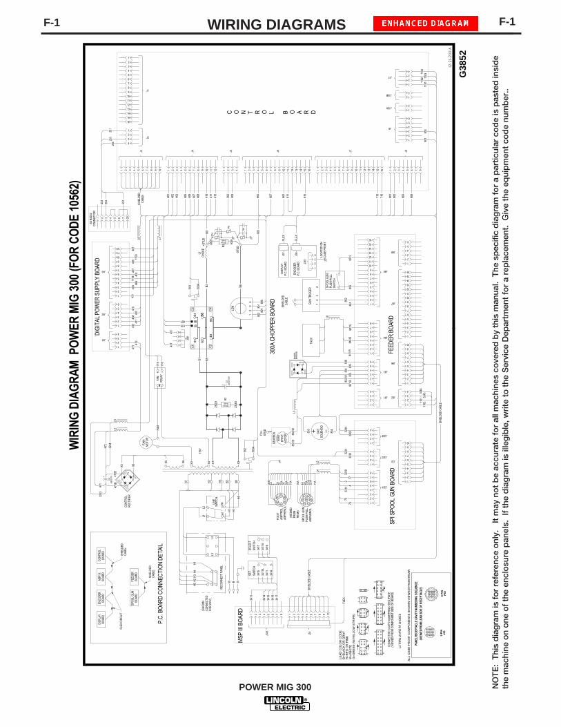
POWER MIG 300
F-1 F-1WIRING DIAGRAMS
NO
TE
: T
his
dia
gra
m is
fo
r re
fere
nce
onl
y.
It m
ay n
ot
be
accu
rate
fo
r al
l mac
hine
s co
vere
d b
y th
is m
anua
l. T
he s
pec
ific
dia
gra
m f
or
a p
artic
ular
co
de
is p
aste
d in
sid
eth
e m
achi
ne o
n o
ne o
f th
e en
clo
sure
pan
els.
If
the
dia
gra
m is
ille
gib
le, w
rite
to
the
Ser
vice
Dep
artm
ent
for
a re
pla
cem
ent.
Giv
e th
e eq
uip
men
t co
de
num
ber
..
ALL
CA
SE
FR
ONT
CO
MP
ON
EN
TS S
HO
WN
VIE
WE
D F
RO
M R
EA
R.
PAN
EL R
ECEP
TAC
LE C
AVI
TY N
UM
BER
ING
SEQ
UEN
CE
(VIE
WED
FRO
M L
EAD
SID
E O
F R
ECEP
TAC
LE)
9 P
INJ5
0
12
3 65
49
87
32
1 45
67
89
9 P
INP
50
LEA
D C
OLO
R C
OD
E:
B=B
LAC
K O
R G
RAY
R=R
ED
OR
PIN
KW
=WH
ITE
G=G
RE
EN
(W/Y
ELL
OW
STR
IPE
)
12-21-2001A
G38
52
WIR
ING
DIA
GR
AM
PO
WER
MIG
300
(FO
R C
OD
E 10
562)
6 12
CON
NEC
TOR
CAV
ITY
NUM
BERI
NG
SEQ
UEN
CE
(VIE
WED
FRO
M C
OM
PON
ENT
SID
E O
F BO
ARD)
1 7
4 8
1 5
3 6
1 4
21
43
6
5 10
1
8 16
1 9
21
6
7 14
1
J4
1 2 3 4 5 6 7 8 9 10 11 12
J3
1 2 3 4 5 6 7 8 9 10
J7
1 2 3 4 5 6 7 8 9 10 11 12 13 14 15 16
J9
1
2
3
4
5
6
J8
1 2 3 4 5 6 7 8
J2
1
2
3
4
J10B1
2
J11
1
2
3
4
1
2
J6
1 2 3 4 5 6 7 8 9 10 11 12 13 14 15 16
J5
1 2 3 4
J1
1
2
3
4
5
6
7
8
9
10
11
12
13
14
15
16
J10A
C O N T R O L B O A R D
J81
1
2
3
4
J82
1
2
3
4
J83
1
2
3
4
5
6 J86
1
2
3
4
5
6
7
8
9
10
J85
1
2
3
4
5
6
7
8
9
10
11
12
13
14
15
16
J87
1
2
3
4
5
6
7
8
9
10
11
12
13
14
15
16
J84
1
2
3
4
5
6
7
8
110111
02 110311
0411
021101
J41
1
2
3
4
J43
1
2
3
4
5
6
7
8
9
10
11
12
J42
1
2
3
4
5
6
DIG
ITAL
PO
WER
SU
PPLY
BO
ARD
FEED
ER B
OAR
D
844:
B84
7:U
841:
R
TACH
GU
N T
RIG
GER
12
34
85185
2
855
832:
W83
1:B
834
833
836
835
GAS
SOLE
NO
ID
833
834
806
804
802
801
716
715
615
604
607
604
412
411
410
408
407
406
405
403
402
401
WIR
EDR
IVE
MO
TOR
GEA
RBO
X
TO +
STU
D
901
903
502
-
+
BR
IDG
ED
IOD
E
FAN
MO
TOR
ENC
OD
ERP.
C. B
OAR
D
DISP
LAY
P.C.
BO
ARD
FLEX
50watts500ohms
2520
2530
471 47
241
2 41140
8 407
403 40
640
240
541
040
1
901
903
715
716
+ -
LEM
12
34
802 80
4801 80
6
+STU
D
-STU
D
502
503A
FAN
REL
AY~
FAN
L1C
HOKE
REC
ON
NEC
T PA
NEL
LIN
ESW
ITC
H
H1
H2
H5
H3
H4
115V
X3 X4 X1 X2
H1
H4
L2L1
H1
W B G
L1L2
H5
H2H
3H4
1
2
3
4
5
6
J88
ENC
OD
ERBO
ARD
MSP
III
BOAR
DD
ISPL
AYBO
ARD
611
503
E
FA
BC
D
R2
CONT
ROL
REC
TIFI
ER
TP6
903B
901B
TP5
TP4
R1
50watts500ohms
8512
J32
1
2
3
4
5
6
7
8
9
101
2
3
4
3244
3243
1
2
3
4
3234
3233
1
2
3
4
5
6
7576
3214
24
SPI S
POO
L GU
N B
OAR
D
3244
3243
J34
1 2 3 4 5 6 7 8 9 10
FLEX
J341
1 2 3 4 5 6 7 8
J321
7
8
J323
J324
3218
77
EF A
BCD
SPO
OL G
UN
/PU
SH-P
ULL
SWIT
CH
G
GND
4A 4 2 76A
4A 2A 75A
3218
3214
77A
2A 75 75A
76 76A
77 77A
FOO
TAM
PTRO
LAM
PHEN
OL
SPO
OL G
UN
/PU
SH-P
ULL
AMPH
ENO
L
(VIE
WED
FRO
MR
EAR
)
MSP
III B
OAR
D
3414
3411
3411
A34
15SW
ITC
HSE
T
3416
3411
A34
17SW
ITCH
SELE
CT
3411
3414
3415
3416
3417
X5 X6
-+
C6
+
X6X5
6800
/75
C5
+ 2400
/100
615607 B8
B7
C1
C2
C3
C4
B1
B3
B2
B4
B6
B5
300A
CH
OPP
ER B
OAR
D
(SHO
WN
CO
NN
ECTE
DFO
R 23
0V)
3234
472
471
3233
471B
472B
SHIE
LDED
CAB
LE
L5L4
L8
L383
1:B
832:
WL2
L7L6
1104
1103
503
503A B6B2
B5B1 B5
L2 T
HRU
L9
ARE
RF
CHO
KES
SHIE
LDED
CAB
LE
437
431
J99
1
2
3
4
437
431
1 2 3 4 5 6 7 20
253
254
251
254
253
251
SHIE
LDED
CAB
LE
S3 R
S232
CO
NN
ECTO
R
SHIE
LDED
CAB
LE
P.C.
BO
ARD
CO
NNEC
TIO
N D
ETAI
L
SPO
OL G
UNBO
ARD
FEED
ERBO
ARD
J37
J36
FLEX
J361
1
2
3
4
LOC
ATED
ON
CAS
E FR
ON
T
CO
NTR
OL
BOAR
D
FLEX
CIR
CU
ITSH
IELD
EDC
ABLE
SHIE
LDED
CAB
LE
H1
H4
H1
L9

F-2 F-2WIRING DIAGRAMS
NO
TE
: T
his
dia
gra
m is
fo
r re
fere
nce
onl
y.
It m
ay n
ot
be
accu
rate
fo
r al
l mac
hine
s co
vere
d b
y th
is m
anua
l. T
he s
pec
ific
dia
gra
m f
or
a p
artic
ular
co
de
is p
aste
d in
sid
eth
e m
achi
ne o
n o
ne o
f th
e en
clo
sure
pan
els.
If
the
dia
gra
m is
ille
gib
le, w
rite
to
the
Ser
vice
Dep
artm
ent
for
a re
pla
cem
ent.
Giv
e th
e eq
uip
men
t co
de
num
ber
..
ALL
CA
SE F
RO
NT
CO
MPO
NEN
TS S
HO
WN
VIE
WED
FR
OM
RE
AR.
PAN
EL R
ECEP
TAC
LE C
AVI
TY N
UM
BER
ING
SEQ
UEN
CE
(VIE
WED
FR
OM
LEAD
SID
E O
F R
ECEP
TAC
LE)
9 P
INJ5
0
12
3 65
49
87
32
1 45
67
89
9 P
INP
50
LEAD
CO
LOR
CO
DE:
B=BL
ACK
OR
GRA
YR=
RED
OR
PIN
KW
=WH
ITE
G=G
REEN
(W/Y
ELLO
W S
TRIP
E)
WIR
ING
DIA
GR
AM
PO
WER
MIG
300
(FO
R C
OD
ES 1
0952
ON
LY)
6 12
CO
NNE
CTO
R C
AVIT
Y N
UM
BER
ING
SEQ
UEN
CE(V
IEW
ED F
RO
M C
OM
PONE
NT
SIDE
OF
BOAR
D)
1 74 8
1 5
3 6
1 4
21
43 6
5 10
18 16
1 9
21
6
7 14
1
J4
1 2 3 4 5 6 7 8 9 10 11 12
J3
1 2 3 4 5 6 7 8 9 10
J7
1 2 3 4 5 6 7 8 9 10 11 12 13 14 15 16
J9
1
2
3
4
5
6
J8
1 2 3 4 5 6 7 8
J2
1
2
3
4
J10B1
2
J11
1
2
3
4
1
2
J6
1 2 3 4 5 6 7 8 9 10 11 12 13 14 15 16
J5
1 2 3 4
J1
1
2
3
4
5
6
7
8
9
10
11
12
13
14
15
16
J10A
C O N T R O L B O A R D
J81
1
2
3
4
J82
1
2
3
4
J83
1
2
3
4
5
6 J86
1
2
3
4
5
6
7
8
9
10
J87
1
2
3
4
5
6
7
8
9
10
11
12
13
14
15
16
J84
1
2
3
4
5
6
7
8
110111
02 110311
0411
021101
J41
1
2
3
4
J43
1
2
3
4
5
6
7
8
9
10
11
12
J42
1
2
3
4
5
6
DIG
ITAL
PO
WER
SU
PPLY
BO
ARD
FEED
ER B
OAR
D
844:
B84
7:U
841:
R
TAC
H
832
831
834
833
836
835
GAS
SOLE
NO
ID
833
834
806
804
802
801
716
715
615
604
607
604
412
411
410
408
407
406
405
403
402
401
WIR
ED
RIVE
MO
TOR
GEA
RBO
X
TO +
STU
D
901
903
502
-
+
BR
IDG
ED
IOD
E
FAN
MO
TOR
DIS
PLAY
P.C.
BO
ARD
50watts500ohms
2520
2530
471 47
241
2 41140
8 407
403 40
640
240
541
040
1
901
903
715
716
+ -
LEM
12
34
802 80
4801 80
6
+STU
D
-STU
D
502
503A
FAN
REL
AY~
FAN
L1C
HOKE
REC
ON
NEC
T PA
NEL
LINE
SWIT
CH
H1
H2
H5
H3
H4
115V
X3 X4 X1 X2
H1
H4
L2L1
H1
W B G
L1L2
H5
H2
H3
H4
1
2
3
4
5
6
J88
MSP
III
BOAR
DD
ISPL
AYBO
ARD
611
503
E
FA
B
C
D
R2
CO
NTR
OL
REC
TIFI
ER
TP6
903B
901B
TP5
TP4
R1
50watts500ohms
J32
1
2
3
4
5
6
7
8
9
101
2
3
4
3244
3243
1
2
3
4
3234
3233
1
2
3
4
5
6
7576
3214
24
SPI S
POO
L G
UN B
OAR
D
3244
3243
J34
2 3 4 5 6 7 8 9 10
FLEX
J341
1 2 3 4 5 6 7 8
J321
7
8
J323
J324
3218
77
EF A
BCD
G
GN
D4A 4 2 76
A
4A 2A 75A
3218
3214
77A
2A 75 75A
76 76A
77 77A
FOO
TAM
PTR
OL
AMPH
ENO
L
SPO
OL
GUN
/PU
SH-P
ULL
AMPH
ENO
L
(VIE
WED
FRO
MRE
AR)
MSP
III B
OAR
D
3414
3411
3411
A34
15SW
ITC
HSE
T
3416
3411
A34
17SW
ITC
HSE
LEC
T34
11
3414
3415
3416
3417
X5 X6
-+
C6
+
X6X5
6800
/75
C5
+ 2400
/100
615607 B8
B7
C1
C2
C3
C4
B1
B3
B2
B4
B6
B5
300A
CHO
PPER
BO
ARD
(SH
OWN
CO
NNE
CTE
DFO
R 2
30V)
3234
472
471
3233
471B
472B
SHIE
LDED
CAB
LE
L5L4
L8
L383
1:B
832:
WL2
L7L6
1104
1103
503
503A B6B2
B5B1 B5
L2 T
HR
U L
9 AR
E R
F CH
OKE
S
437
431
J99
1
2
3
4
437
431
1 2 3 4 5 6 7 20
253
254
251
254
253
251
SHIE
LDED
CAB
LE
S3 R
S232
CO
NNE
CTO
R
SHIE
LDED
CABL
E
P.C.
BO
ARD
CONN
ECTI
ON
DETA
IL
SPO
OL
GUN
BOAR
DFE
EDER
BOAR
D
J37
FLEX
CO
NTR
OL
BOAR
D
FLEX
CIR
CUI
TSH
IELD
EDC
ABLE
SHIE
LDED
CAB
LE
H1
H4
H1
L9
PANE
L EN
CODE
RSVO
LTS/
TRIM
WFS
/AM
PS
858
857 85
985101
23
12
3 16
15
14
13
12
11
10
9
8
7
6
5
4
3
2
1
J85
SPO
OL
GUN
/PU
SH-P
ULL
SWIT
CH
8512
855
852
851
43
21
GUN
TRIG
GER
8511
855A
A
G40
68
POWER MIG 300

F-3 F-3WIRING DIAGRAMS
NO
TE
: T
his
dia
gra
m is
fo
r re
fere
nce
onl
y.
It m
ay n
ot
be
accu
rate
fo
r al
l mac
hine
s co
vere
d b
y th
is m
anua
l. T
he s
pec
ific
dia
gra
m f
or
a p
artic
ular
co
de
is p
aste
d in
sid
eth
e m
achi
ne o
n o
ne o
f th
e en
clo
sure
pan
els.
If
the
dia
gra
m is
ille
gib
le, w
rite
to
the
Ser
vice
Dep
artm
ent
for
a re
pla
cem
ent.
Giv
e th
e eq
uip
men
t co
de
num
ber
..
WIR
ING
DIA
GR
AM
PO
WE
R M
IG 3
00 (
FO
R C
OD
ES
109
58 A
ND
110
00)
POWER MIG 300
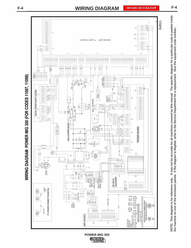
F-4F-4 WIRING DIAGRAM
POWER MIG 300
WIR
ING
DIA
GR
AM
PO
WER
MIG
300
(FO
R C
OD
ES 1
1097
, 110
98)
J4
1 2 3 4 5 6 7 8 9 10 11 12
J3
1 2 3 4 5 6 7 8 9 10
J7
1 2 3 4 5 6 7 8 9 10 11 12 13 14 15 16
J9
1
2
3
4
5
6
J8
1 2 3 4 5 6 7 8
J2
1
2
3
4
J10B1
2
J11
1
2
3
4
1
2
J6
1 2 3 4 5 6 7 8 9 10 11 12 13 14 15 16
J5
1 2 3 4
J1
1
2
3
4
5
6
7
8
9
10
11
12
13
14
15
16
J10A
C O N T R O L B O A R D
J81
1
2
3
4
J82
J83
1
2
3
4
5
6
J86
1 2 3 4 5 6 7 8 9 10
J87
1
2
3
4
5
6
7
8
9
10
11
12
13
14
15
16
J84
1
2
3
4
5
6
7
8
110111
02 110311
04
1102 11
01
J41
1
2
3
4
J43
1
2
3
4
5
6
7
8
9
10
11
12
J42
1
2
3
4
5
6
DIG
ITAL
PO
WER
SU
PPLY
BO
ARD
FEED
ER B
OAR
D
844:
B84
7:U
841:
R83
283
183
483
383
683
5
806
804
802
801
716
715
615
604
607
604
412
411
410
408
407
406
405
403
402
401
WIR
E D
RIV
EM
OTO
R
GEA
RBO
X
TO +
STU
D
901
903
502
FAN
MO
TOR
DIS
PLAY
P.C
. BOA
RD
50watts500ohms
2520
2530
471 47
241
2 41140
8 407
403 40
640
240
541
040
1
901
903
715
716
+ -
LEM
12
34
802 80
4801 80
6
+STU
D
-STU
D50
2
503A
FAN
REL
AY~
FAN
L1C
HO
KE
REC
ON
NEC
T PA
NEL
LINE
SWIT
CH
H1
H2
H5
H3
H4
115V
X3 X4 X1 X2
H1
H4
L2L1
H1
W B G
L1L2
H5
H2
H3
H4
1
2
3
4
5
6
J88
MSP
III
BOAR
DD
ISPL
AYBO
ARD
611
503
R2
CO
NTR
OL
REC
TIFI
ER
TP6
903B
901B
TP5
TP4
R1
50watts500ohms
3234
3233
J34
2 3 4 5 6 7 8 9 10
FLEX
J341
1 2 3 4 5 6 7 8
MSP
III B
OAR
D
3414
3411
3411
A34
15SW
ITC
HSE
T34
11
3414
3415
3416
3417
X5 X6
-+
C6
+
X6X5
6800
/75
C5
+ 2400
/100
615607 B8
B7
C1
C2
C3
C4
B1
B3
B2
B4
B6
B5
300A
CHO
PPER
BO
ARD
(SH
OW
NC
ON
NEC
TED
FOR
230
V)
3234
472
471
3233
471B
472B
L3
BW
L2
L7L6
1104
1103
503
503A B6B2
B5B1 B5
1 2 3 4 5 6 7 20
253
254
251
254
253
251
SHIE
LDED
CAB
LE
S3 R
S232
CO
NNE
CTO
R
SHIE
LDED
CAB
LE
P.C.
BO
ARD
CO
NNE
CTI
ON
DET
AIL
J37
FLEX
CO
NTR
OL
BOAR
D
FLEX
CIR
CUIT
SHIE
LDED
CABL
E
H1
H4
H1
L9
PAN
EL E
NC
ODE
RS
VOLT
S/TR
IMW
FS/A
MPS
858
857 85
985101
23
12
3 16
15
14
13
12
11
10
9
8
7
6
5
4
3
2
1
J85
8512
852
851
8511
855A
G45
11
1
2
3
4
5
6
7
8
BW
A
P86
12345678910
SPI S
POO
LG
UN B
OAR
D
J89J811
J810
123456789101 2
L2 T
HR
U L
9 ARE
RF
CH
OKE
S
1
147
6
1 2
91
1681
105
634
12
41
63
51
84 71
(VIE
WED
FR
OM
CO
MPO
NEN
T SI
DE O
F BO
ARD
)C
ON
NEC
TOR
CAV
ITY
NU
MBER
ING
SEQ
UEN
CE
126
LEAD
CO
LOR
CO
DE:
B=BL
ACK
OR
GR
AYR
=RED
OR
PIN
KW
=WH
ITE
G=G
REE
N (W
/YEL
LOW
STR
IPE)
9 P
INP
50
98
76
541
23
78
94
563
21
9 P
INJ5
0
PAN
EL R
ECEP
TAC
LE C
AVI
TY N
UM
BER
ING
SEQ
UEN
CE
(VIE
WED
FRO
M L
EAD
SID
E OF
REC
EPTA
CLE
)
ALL
CA
SE F
RO
NT
CO
MPO
NE
NTS
SH
OW
N V
IEW
ED
FR
OM
RE
AR
.
3218
75
-
+
BRID
GE
DIO
DE
1 2 3 4 5 6
3214
TAC
H
L8
855
SPO
OL
GU
N/
PUSH
-PU
LLSW
ITC
H
853
2B
TRIG
GER
DU
AL
PRO
CED
URE
43
21
4
834
833
GAS
SOLE
NO
ID
853
8514
L4L5
(VIE
WED
FRO
M R
EAR
)
SPO
OL
GU
NPU
SH-P
ULL
AMPH
ENO
L
FOO
TAM
PTR
OL
AMPH
ENO
L77
A7776
A7675
A752A
77A
321432
1875
A2A4A
76A
244A
GD C
BAF
E
D
C
BA
FE
GND
SELE
CT
SWIT
CH
3417
3411
A34
16
8514
8111
8115
8111
836
8115
1
2
3
4
7 8
77 76 846A
846
846
851A
2
NO
TE
: T
his
dia
gra
m is
fo
r re
fere
nce
onl
y.
It m
ay n
ot
be
accu
rate
fo
r al
l mac
hine
s co
vere
d b
y th
is m
anua
l. T
he s
pec
ific
dia
gra
m f
or
a p
artic
ular
co
de
is p
aste
d in
sid
eth
e m
achi
ne o
n o
ne o
f th
e en
clo
sure
pan
els.
If
the
dia
gra
m is
ille
gib
le, w
rite
to
the
Ser
vice
Dep
artm
ent
for
a re
pla
cem
ent.
Giv
e th
e eq
uip
men
t co
de
num
ber
..

DIMENSION PRINTF-5
POWER MIG 300
F-5
3-00
F
M19
231

NOTES
POWER MIG 300

NOTES
POWER MIG 300

WARNING
AVISO DEPRECAUCION
ATTENTION
WARNUNG
ATENÇÃO
Spanish
French
German
Portuguese
Japanese
Chinese
Korean
Arabic
READ AND UNDERSTAND THE MANUFACTURER’S INSTRUCTION FOR THIS EQUIPMENT AND THE CONSUMABLES TO BEUSED AND FOLLOW YOUR EMPLOYER’S SAFETY PRACTICES.
SE RECOMIENDA LEER Y ENTENDER LAS INSTRUCCIONES DEL FABRICANTE PARA EL USO DE ESTE EQUIPO Y LOSCONSUMIBLES QUE VA A UTILIZAR, SIGA LAS MEDIDAS DE SEGURIDAD DE SU SUPERVISOR.
LISEZ ET COMPRENEZ LES INSTRUCTIONS DU FABRICANT EN CE QUI REGARDE CET EQUIPMENT ET LES PRODUITS AETRE EMPLOYES ET SUIVEZ LES PROCEDURES DE SECURITE DE VOTRE EMPLOYEUR.
LESEN SIE UND BEFOLGEN SIE DIE BETRIEBSANLEITUNG DER ANLAGE UND DEN ELEKTRODENEINSATZ DES HER-STELLERS. DIE UNFALLVERHÜTUNGSVORSCHRIFTEN DES ARBEITGEBERS SIND EBENFALLS ZU BEACHTEN.
● Do not touch electrically live parts orelectrode with skin or wet clothing.
● Insulate yourself from work andground.
● No toque las partes o los electrodosbajo carga con la piel o ropa moja-da.
● Aislese del trabajo y de la tierra.
● Ne laissez ni la peau ni des vête-ments mouillés entrer en contactavec des pièces sous tension.
● Isolez-vous du travail et de la terre.
● Berühren Sie keine stromführendenTeile oder Elektroden mit IhremKörper oder feuchter Kleidung!
● Isolieren Sie sich von denElektroden und dem Erdboden!
● Não toque partes elétricas e elec-trodos com a pele ou roupa molha-da.
● Isole-se da peça e terra.
● Keep flammable materials away.
● Mantenga el material combustiblefuera del área de trabajo.
● Gardez à l’écart de tout matérielinflammable.
● Entfernen Sie brennbarres Material!
● Mantenha inflamáveis bem guarda-dos.
● Wear eye, ear and body protection.
● Protéjase los ojos, los oídos y elcuerpo.
● Protégez vos yeux, vos oreilles etvotre corps.
● Tragen Sie Augen-, Ohren- und Kör-perschutz!
● Use proteção para a vista, ouvido ecorpo.

WARNING
AVISO DEPRECAUCION
ATTENTION
WARNUNG
ATENÇÃO
Spanish
French
German
Portuguese
Japanese
Chinese
Korean
Arabic
LEIA E COMPREENDA AS INSTRUÇÕES DO FABRICANTE PARA ESTE EQUIPAMENTO E AS PARTES DE USO, E SIGA ASPRÁTICAS DE SEGURANÇA DO EMPREGADOR.
● Keep your head out of fumes.● Use ventilation or exhaust to
remove fumes from breathing zone.
● Los humos fuera de la zona de res-piración.
● Mantenga la cabeza fuera de loshumos. Utilice ventilación oaspiración para gases.
● Gardez la tête à l’écart des fumées.● Utilisez un ventilateur ou un aspira-
teur pour ôter les fumées des zonesde travail.
● Vermeiden Sie das Einatmen vonSchweibrauch!
● Sorgen Sie für gute Be- undEntlüftung des Arbeitsplatzes!
● Mantenha seu rosto da fumaça.● Use ventilação e exhaustão para
remover fumo da zona respiratória.
● Turn power off before servicing.
● Desconectar el cable de ali-mentación de poder de la máquinaantes de iniciar cualquier servicio.
● Débranchez le courant avant l’entre-tien.
● Strom vor Wartungsarbeitenabschalten! (Netzstrom völlig öff-nen; Maschine anhalten!)
● Não opere com as tampas removidas.● Desligue a corrente antes de fazer
serviço.● Não toque as partes elétricas nuas.
● Do not operate with panel open orguards off.
● No operar con panel abierto oguardas quitadas.
● N’opérez pas avec les panneauxouverts ou avec les dispositifs deprotection enlevés.
● Anlage nie ohne Schutzgehäuseoder Innenschutzverkleidung inBetrieb setzen!
● Mantenha-se afastado das partesmoventes.
● Não opere com os paineis abertosou guardas removidas.

• Sales and Service through Subsidiaries and Distributors Worldwide •Cleveland, Ohio 44117-1199 U.S.A. TEL: 216.481.8100 FAX: 216.486.1751 WEB SITE: www.lincolnelectric.com
• World's Leader in Welding and Cutting Products •


