
Brigham Young University Brigham Young University
BYU ScholarsArchive BYU ScholarsArchive
Theses and Dissertations
2011-03-17
Increasing Design Productivity for FPGAs Through IP Reuse and Increasing Design Productivity for FPGAs Through IP Reuse and
Meta-Data Encapsulation Meta-Data Encapsulation
Adam T. Arnesen Brigham Young University - Provo
Follow this and additional works at: https://scholarsarchive.byu.edu/etd
Part of the Electrical and Computer Engineering Commons
BYU ScholarsArchive Citation BYU ScholarsArchive Citation Arnesen, Adam T., "Increasing Design Productivity for FPGAs Through IP Reuse and Meta-Data Encapsulation" (2011). Theses and Dissertations. 2614. https://scholarsarchive.byu.edu/etd/2614
This Thesis is brought to you for free and open access by BYU ScholarsArchive. It has been accepted for inclusion in Theses and Dissertations by an authorized administrator of BYU ScholarsArchive. For more information, please contact [email protected], [email protected].

Increasing Design Productivity for FPGAs Through Intellectual
Property Reuse and Meta-Data Encapsulation
Adam Arnesen
A thesis submitted to the faculty ofBrigham Young University
in partial fulfillment of the requirements for the degree of
Master of Science
Michael J. Wirthlin, ChairBrad L. HutchingsBrent E. Nelson
Department of Electrical and Computer Engineering
Brigham Young University
April 2011
Copyright c© 2011 Adam Arnesen
All Rights Reserved


ABSTRACT
Increasing Design Productivity for FPGAs Through Intellectual
Property Reuse and Meta-Data Encapsulation
Adam Arnesen
Department of Electrical and Computer Engineering
Master of Science
As Moore’s law continues to progress, it is becoming increasingly difficult for hardwaredesigners to fully utilize the increasing number of transistors available semiconductor devicesincluding FPGAs. This design productivity gap must be addressed to allow designs to takefull advantage of the increased logic density that results from rising transistor density.
The reuse of previously developed and verified intellectual property (IP) is one ap-proach that has claimed to narrow the design productivity gap. Reuse, however, has proveddifficult to realize in practice because of the complexity of IP and the reluctance of designersto reuse IP that they do not understand. This thesis proposes to narrow the design pro-ductivity gap for FPGAs by simplifying the reuse problem by encapsulating IP with extramachine-readable information or meta-data. This meta-data simplifies reuse by providing alanguage independent format for composing complex systems, providing a parameter repre-sentation system, defining high-level data types for FPGA IP, and allowing arbitrary IP tobe described as actors in the homogeneous synchronous dataflow model of computation.
This work implements meta-data in XML and presents two XML schemas that enablereuse. A new XML schema known as CHREC XML is presented as well as extensions thatenable IP-XACT to be used to describe FPGA dataflow IP. Two tools developed in thiswork are also presented that leverage meta-data to simplify reuse of arbitrary IP. Thesetools simplify structural composition of IP, allow designers to manipulate parameters, checkand validate high-level data types, and automatically synthesize control circuitry for dataflowdesigns. Productivity improvements are also demonstrated by reusing IP to quickly composesoftware radio receivers.
Keywords: meta-data, FPGA, intellectual property reuse, interface synthesis, IP-XACT,synchronous dataflow, architectural synthesis


ACKNOWLEDGMENTS
I would like to thank my advisor, Mike Wirthlin, and my committee members Brent
Nelson and Brad Hutchings who have encouraged me in my work. I would also like to
thank my other professors at BYU who have mentored me through my undergraduate and
graduate studies and who have provided opportunities for learning and inspiration for my
studies. I am grateful for the support and help of Marc Padilla who helped me design
communication systems, Derrick Gibelyou for helping with algorithms and data structures,
and the other students in the BYU Configurable Computing Laboratory who have helped
me in my research
My family also deserves thanks for supporting me throughout my education. My
parents have encouraged my academic work from my elementary school years and have
always helped me to push myself to be my best. My loving wife Sarah also deserves my
deepest thanks. She has been patient and supportive as I have spent long hours in school
and research. She has been an unfailing source of love and support.
I would also like to thank Newton Peterson, HoJin Kee, and Jeff Washington at
National Instruments for their support of my ideas and their encouragement of me to pursue
my education.
This work was supported by a grant from The Rocky Mountain NASA Space Grant
Consortium, as well as by Brigham Young University CHREC center funded by the I/UCRC
Program of the National Science Foundation under Grant No. 0801876.


Table of Contents
List of Tables xiii
List of Figures xvi
1 Introduction: Design Productivity and Reuse 1
1.1 The Design Productivity Gap for FPGAs . . . . . . . . . . . . . . . . . . . . 2
1.2 Increasing Design Productivity . . . . . . . . . . . . . . . . . . . . . . . . . . 4
1.3 IP Reuse . . . . . . . . . . . . . . . . . . . . . . . . . . . . . . . . . . . . . . 5
1.4 Enabling Reuse with Meta-Data . . . . . . . . . . . . . . . . . . . . . . . . . 7
1.5 Thesis Contributions . . . . . . . . . . . . . . . . . . . . . . . . . . . . . . . 7
2 IP Reuse and Meta-Data Descriptions 11
2.1 Meta-Data for HDL Reuse . . . . . . . . . . . . . . . . . . . . . . . . . . . . 12
2.2 Meta-Data in Commercial Design Tools . . . . . . . . . . . . . . . . . . . . . 13
2.2.1 Xilinx CORE Generator . . . . . . . . . . . . . . . . . . . . . . . . . 13
2.2.2 Xilinx EDK . . . . . . . . . . . . . . . . . . . . . . . . . . . . . . . . 14
2.2.3 Xilinx System Generator . . . . . . . . . . . . . . . . . . . . . . . . . 14
2.2.4 National Instruments LabVIEW FPGA . . . . . . . . . . . . . . . . . 15
3 XML-Based Meta-Data for Reuse 17
3.1 XML as a Meta-Data Format . . . . . . . . . . . . . . . . . . . . . . . . . . 18
3.2 CHREC XML . . . . . . . . . . . . . . . . . . . . . . . . . . . . . . . . . . . 19
vii

3.2.1 Segment 1: The Structural Segment . . . . . . . . . . . . . . . . . . . 20
3.2.2 Segment 2: High-Level Datatype Segment . . . . . . . . . . . . . . . 20
3.2.3 Segment 3: Temporal Behavior . . . . . . . . . . . . . . . . . . . . . 21
3.2.4 Weaknesses of CHREC XML . . . . . . . . . . . . . . . . . . . . . . 21
3.3 IP-XACT and Extensions . . . . . . . . . . . . . . . . . . . . . . . . . . . . 23
3.3.1 Parameterization and Mathematical Expressions . . . . . . . . . . . . 24
3.3.2 Ports and Structural Interface . . . . . . . . . . . . . . . . . . . . . . 25
3.3.3 Generator Chains . . . . . . . . . . . . . . . . . . . . . . . . . . . . . 27
3.3.4 Modifying IP-XACT for FPGA IP . . . . . . . . . . . . . . . . . . . 28
3.3.5 Extensions for High-Level Datatypes . . . . . . . . . . . . . . . . . . 29
3.3.6 Extensions for Temporal Interface Behavior . . . . . . . . . . . . . . 31
4 Meta-Data Enabled Design Environment 33
4.1 A Structural Design GUI . . . . . . . . . . . . . . . . . . . . . . . . . . . . . 33
4.2 Parameter Representation and Manipulation . . . . . . . . . . . . . . . . . . 37
4.2.1 Traditional Low-Level Parameterization . . . . . . . . . . . . . . . . 37
4.2.2 High-Level Parameterization . . . . . . . . . . . . . . . . . . . . . . . 38
4.2.3 Parameter Dependencies and Translation . . . . . . . . . . . . . . . . 39
4.2.4 A Parameter Manipulation GUI . . . . . . . . . . . . . . . . . . . . . 40
4.3 Language-Specific Wrapper Generation . . . . . . . . . . . . . . . . . . . . . 43
5 Meta-Data Enabled H-SDF Synthesis Using IP 45
5.1 Numerical Datatypes . . . . . . . . . . . . . . . . . . . . . . . . . . . . . . . 47
5.1.1 Representing Datatypes . . . . . . . . . . . . . . . . . . . . . . . . . 48
5.1.2 Utilizing Numerical Types . . . . . . . . . . . . . . . . . . . . . . . . 49
5.2 Representing Coarse-Grained IP as H-SDF Actors . . . . . . . . . . . . . . . 50
viii

5.2.1 The H-SDF Model of Computation . . . . . . . . . . . . . . . . . . . 50
5.2.2 Latency . . . . . . . . . . . . . . . . . . . . . . . . . . . . . . . . . . 53
5.2.3 Data Introduction Interval . . . . . . . . . . . . . . . . . . . . . . . . 54
5.2.4 Sample Delay . . . . . . . . . . . . . . . . . . . . . . . . . . . . . . . 54
5.2.5 IP-XACT Extensions for H-SDF . . . . . . . . . . . . . . . . . . . . . 55
5.3 Applying H-SDF Synthesis Techniques to Coarse-Grain IP . . . . . . . . . . 56
5.3.1 Translating Schematics to H-SDF Graphs . . . . . . . . . . . . . . . 57
5.3.2 Applying Iterative Modulo Scheduling . . . . . . . . . . . . . . . . . 59
5.3.3 Control Synthesis . . . . . . . . . . . . . . . . . . . . . . . . . . . . . 61
6 Meta-Data Enabled Rapid Radio Development 65
6.1 A Highly Parameterized IP Library . . . . . . . . . . . . . . . . . . . . . . . 65
6.2 Manually Constructing Radios . . . . . . . . . . . . . . . . . . . . . . . . . . 68
6.3 Automatic Radio Generation . . . . . . . . . . . . . . . . . . . . . . . . . . . 70
7 Conclusion: Productivity Gains from Meta-Data-Assisted Reuse 73
7.1 Productivity Increases Demonstrated . . . . . . . . . . . . . . . . . . . . . . 73
7.2 The Role of Meta-Data in Reuse . . . . . . . . . . . . . . . . . . . . . . . . . 75
7.3 Future Work . . . . . . . . . . . . . . . . . . . . . . . . . . . . . . . . . . . . 77
7.4 The Need for Increased Design Productivity . . . . . . . . . . . . . . . . . . 79
Bibliography 81
A CHREC XML Extensions to IP-XACT 85
A.1 Extending IP-XACT . . . . . . . . . . . . . . . . . . . . . . . . . . . . . . . 85
A.2 Parameter Extensions . . . . . . . . . . . . . . . . . . . . . . . . . . . . . . . 86
A.3 Port Description Extensions . . . . . . . . . . . . . . . . . . . . . . . . . . . 87
ix

A.4 High Level Datatypes Extension . . . . . . . . . . . . . . . . . . . . . . . . . 88
A.4.1 Bit Vector . . . . . . . . . . . . . . . . . . . . . . . . . . . . . . . . . 89
A.4.2 Integer . . . . . . . . . . . . . . . . . . . . . . . . . . . . . . . . . . . 89
A.4.3 Floating Point . . . . . . . . . . . . . . . . . . . . . . . . . . . . . . . 89
A.4.4 Fixed Point . . . . . . . . . . . . . . . . . . . . . . . . . . . . . . . . 89
A.4.5 Custom Type . . . . . . . . . . . . . . . . . . . . . . . . . . . . . . . 89
A.5 Behavioral Layer Extension . . . . . . . . . . . . . . . . . . . . . . . . . . . 90
A.5.1 Pipeline Depth . . . . . . . . . . . . . . . . . . . . . . . . . . . . . . 90
A.5.2 Data Introduction Interval . . . . . . . . . . . . . . . . . . . . . . . . 91
A.5.3 Sample Delay . . . . . . . . . . . . . . . . . . . . . . . . . . . . . . . 91
A.5.4 Signal Associations . . . . . . . . . . . . . . . . . . . . . . . . . . . . 92
B Dataflow Interface Automata 93
B.1 Introduction . . . . . . . . . . . . . . . . . . . . . . . . . . . . . . . . . . . . 93
B.2 Definition and Examples . . . . . . . . . . . . . . . . . . . . . . . . . . . . . 93
B.3 Visualizing DIA’s . . . . . . . . . . . . . . . . . . . . . . . . . . . . . . . . . 102
C The IP-XACT Extensions Schema 105
C.1 CHREC Extensions . . . . . . . . . . . . . . . . . . . . . . . . . . . . . . . . 105
C.2 Parameters . . . . . . . . . . . . . . . . . . . . . . . . . . . . . . . . . . . . 106
C.3 High-Level Datatypes . . . . . . . . . . . . . . . . . . . . . . . . . . . . . . . 108
C.4 H-SDF Interface Definitions . . . . . . . . . . . . . . . . . . . . . . . . . . . 114
C.5 Port Extensions . . . . . . . . . . . . . . . . . . . . . . . . . . . . . . . . . . 116
C.6 Supporting Code . . . . . . . . . . . . . . . . . . . . . . . . . . . . . . . . . 117
D Generated VHDL from Ogre 123
x

D.1 Top-Level VHDL . . . . . . . . . . . . . . . . . . . . . . . . . . . . . . . . . 123
D.2 Finite State Machine . . . . . . . . . . . . . . . . . . . . . . . . . . . . . . . 137
xi

xii
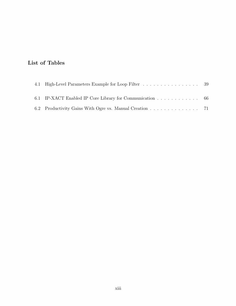
List of Tables
4.1 High-Level Parameters Example for Loop Filter . . . . . . . . . . . . . . . . 39
6.1 IP-XACT Enabled IP Core Library for Communication . . . . . . . . . . . . 66
6.2 Productivity Gains With Ogre vs. Manual Creation . . . . . . . . . . . . . . 71
xiii

xiv

List of Figures
1.1 The Design Productivity Gap . . . . . . . . . . . . . . . . . . . . . . . . . . 2
1.2 A Basic FPGA Fabric . . . . . . . . . . . . . . . . . . . . . . . . . . . . . . 3
3.1 A Generic Design Flow Using Meta-Data . . . . . . . . . . . . . . . . . . . . 17
3.2 Independent Segments of XML in CHREC XML . . . . . . . . . . . . . . . . 19
3.3 The IP-XACT Design Environment . . . . . . . . . . . . . . . . . . . . . . . 24
3.4 Datatype Mismatch Caused by Matching Bitwidths . . . . . . . . . . . . . . 30
4.1 Tool Flow for Creating Wrappers from Multi-Segment CHREC XML . . . . 34
4.2 The CHREC XML Design Composition Tool . . . . . . . . . . . . . . . . . . 35
4.3 High Level Parameters Translated to Low-Level Parameters . . . . . . . . . 40
4.4 Parameter Manipulation GUI Based on CHREC XML . . . . . . . . . . . . 41
5.1 The Ogre Tool-Flow . . . . . . . . . . . . . . . . . . . . . . . . . . . . . . . 46
5.2 The Simulink Front End to Ogre . . . . . . . . . . . . . . . . . . . . . . . . 47
5.3 Tools Synthesis of Datatype Conversion Logic . . . . . . . . . . . . . . . . . 50
5.4 The Homogeneous Synchronous Dataflow Model of Computation . . . . . . . 51
5.5 H-SDF Initial Conditions . . . . . . . . . . . . . . . . . . . . . . . . . . . . . 52
5.6 Design Represented as H-SDF Graphs . . . . . . . . . . . . . . . . . . . . . 58
5.7 Scheduling H-SDF Graphs . . . . . . . . . . . . . . . . . . . . . . . . . . . . 60
6.1 A QPSK System For Input to Ogre . . . . . . . . . . . . . . . . . . . . . . . 69
xv

6.2 Bit Error Rate Curves for Software Radios . . . . . . . . . . . . . . . . . . . 70
B.1 Deterministic Dataflow Interface Automata (DIA) . . . . . . . . . . . . . . . 94
B.2 Deterministic DIA With Control . . . . . . . . . . . . . . . . . . . . . . . . . 96
B.3 Non-deterministic DIA . . . . . . . . . . . . . . . . . . . . . . . . . . . . . . 97
B.4 Non-deterministic DIA for core with required clear . . . . . . . . . . . . . . 99
B.5 A DIA for an Upsampling Core . . . . . . . . . . . . . . . . . . . . . . . . . 100
B.6 A DIA for a Downsampling Core . . . . . . . . . . . . . . . . . . . . . . . . 101
B.7 Full Example of Dataflow Interface Automata Operation . . . . . . . . . . . 103
xvi

Chapter 1
Introduction: Design Productivity and Reuse
As the density of transistors on a semiconductor device continues to increase following
Moore’s Law, designers in the electronics industry have found it increasingly difficult to
utilize the increasing transistor density that is available on silicon devices. The disparity
between the capability of technology and the designer’s ability to utilize it is called the
“design productivity gap.” The increase in the design productivity gap has concerned the
electronics industry for several years. If the gap is not closed significantly, then despite the
improvements in technology the designs the industry produces will not scale at the same
rate as the technology upon which they are implemented.
The trends in productivity and device capability when viewed on their own are en-
couraging because improvements are being observed in both areas as shown in Figure 1.1 [1].
Figure 1.1 shows that there have been improvements in the productivity of engineers de-
signing systems to be implemented on digital hardware. The productivity improvements
are encouraging because the engineer’s productivity is doubling about every 3.5 years. The
steady increase in design productivity is due in part to the progression of tools (verification
methods, design entry methods, etc.) and the ability of designers to design systems at a
higher level (i.e., System-on-Chip). Figure 1.1 also shows encouraging advances in device
capability. The transistor density is increasing as predicted by Moore’s Law, doubling every
1.5 to 2 years.
While both productivity and device capability are improving, comparing the rate of
improvement of productivity and of transistor density reveals the design productivity gap.
For each year that designer productivity increases at its current rate, the transistor density
is increasing at more than double that rate. If this gap continues to increase at its current
1

Figure 1.1: The Design productivity gap for hardware systems [1]. The gap between produc-tivity and technology capability is increasing.
rate, the ability of electronic systems designers to utilize the increasing computing resources
on available platforms will not be able to keep up with the increases in density.
1.1 The Design Productivity Gap for FPGAs
The design productivity gap observed for digital hardware circuits also exists for
field programmable gate arrays (FPGA) and other reconfigurable devices. FPGAs “allow
the computational capacity of the machine to be highly customized to the instantaneous
needs of an application while allowing the computational capacity to be reused many times
for different applications” [2]. FPGAs offer a flexible design implementation solution that
occupies a niche between software implementations that run on a processor and application
specific integrated circuits (ASIC) and other custom silicon solutions.
FPGAs provide an array of customizable hardware blocks and programmable inter-
connect as shown in Figure 1.2 [3]. The logic elements and interconnect can be configured
repeatedly to implement many different hardware designs. Designing for FPGAs is like de-
2

signing software in the sense that in FPGA designs hardware description language (HDL)
code is compiled and then “run” on a the device. The compiled FPGA code represents a
set of configuration instructions that define the behavior of logic blocks and the interconnect
routing in the FPGA fabric.
Figure 1.2: A basic FPGA fabric. Interconnect and logic block contents are both pro-grammable. Dots on interconnect represent programmable connections between wires thatenable signals to route between logic blocks.
Data-flow systems such as digital signal processing are often straight-forward to im-
plement on modern FPGAs because of the natural mapping of these types of systems onto
the FPGA fabric. Because of the abundance of resources, DSP systems can be pipelined and
logically optimized to perform at high clock frequencies. The reconfigurable nature of FPGAs
also allows for data-flow systems to be quickly upgraded as technology demands change. This
work will focus primarily on increasing designer productivity in designing data-flow systems,
particularly on DSP and communication systems implemented on FPGAs.
3

Design productivity challenges for FPGAs are different from the productivity chal-
lenges facing the electronics industry in general. Historically the design challenges for FPGA
design have included meeting timing closure and making designs compact enough that they
will fit on the fabric of a single device. This was especially true for early FPGAs which had
such a small logic density that even basic designs or sometimes a single complex core easily
consumed all of the computational resource available on the device. However, in recent years,
as FPGAs and other reconfigurable devices continue to increase their computing capability
following Moore’s law, the design productivity problem has become more pronounced. The
increase in transistor density has enabled production of devices with many more logic ele-
ments. As the number of available logic elements increases, it becomes increasingly difficult
to utilize all available FPGA logic with a single design.
Low design productivity continues to be a primary barrier to the more widespread
adoption of FPGAs as a computing platform. Unless design productivity for FPGAs signif-
icantly increases, FPGA adoption will be limited to a relatively few dedicated application
and hardware development experts who have the skills necessary to create low-level FPGA
circuits.
1.2 Increasing Design Productivity
The International Technology Roadmap for Semiconductors (ITRS) [1] has outlined
several ways of addressing the increasing design productivity gap for digital semiconductor
systems as well as for FPGAs. These ways include migrating to platform based design,
improving and simplifying high level synthesis, and increasing intellectual property (IP)
reuse.
Platform-based design is essentially a form of component or IP reuse. Platform-based
design is “a meeting-in-the-middle process”, where “successive refinements of specifications
meet with abstractions of potential implementations and the identification of precisely de-
fined layers where the refinement and abstraction processes take place [4].” This means that
platform-based design simplifies the process of mapping a concept system onto an implemen-
tation by providing a large variety of functionality on a single circuit board or even in a single
integrated circuit package. Because of the large amount of pre-built design implementation
4
circuitry, the mapping of ideas to that circuitry as well as the design space exploration are
simplified.
High level synthesis is generally defined as the process of automatically creating dig-
ital circuits by starting with an abstract behavioral specification of a digital system and
finding a register-transfer level (RTL) structure that realizes the behavioral specification [5].
These abstract systems can be specified in a traditional software language such as C and
then translated into a high performance hardware system [6, 7]. High level synthesis gen-
erally maps behavioral specifications to small-sized low-level primitives such as adders and
multipliers. This is a powerful approach to increasing design productivity [5].
Design reuse is the process of designing robust verified, IP and reusing that IP in
future designs. Reuse increases design productivity by avoiding duplication of core design
effort. If a core has been used successfully in an application in the past, the effort spent
designing and testing that IP should not be duplicated when the same functionality is needed
for another application. Leveraging IP reuse to increase productivity is the primary approach
used in this thesis.
1.3 IP Reuse
Reuse of previously verified and tested soft and hard intellectual property (IP) has
long been touted as a primary method of improving design productivity [8] because there
already exists an enormous amount of previously verified and tested hard and soft IP in
the electronic design industry. Easy access to this IP and the ability to quickly and easily
integrate it into designs would drastically narrow the design productivity gap.
Despite the potential of reuse to increase productivity, reuse has been hampered be-
cause it is often difficult to reuse IP. In most current design environments and methodologies,
in order for a designer to successfully reuse IP the designer must 1) manually find and select
the appropriate IP, 2) understand the details of the implementation of the core, and 3) un-
derstand the interface and timing protocol used in order to integrate the IP into an overall
system. Control and interface circuitry often must be manually generated. This is a complex
and time-consuming process that must be done very quickly in order for reuse to be feasible.
IP also often comes from many sources and in many formats, making reuse an intimidating
5

prospect. In fact, in order for any reuse process to be feasible, the entire process must not
require more than 30% of the effort required to create the same IP from scratch [9].
Reuse based on standard platforms and formats has long been used in software en-
gineering and has resulted in significant productivity improvements [10]. Software reuse, in
the form of libraries, is so commonplace that most programmers do not even realize they are
in fact reusing IP when they program. Programmers are able to develop systems by simply
reusing previously developed IP from a library to implement their software system with little
or no knowledge of how the underlying implementation of the IP operates. It is this reuse
and standard method of representing software of IP that has most significantly increased the
design productivity level in software development [11]. The success of this reuse scheme and
the role of standard methods are important to remember as reuse schemes are developed for
hardware IP.
The issues to be overcome to facilitate reuse of IP for general hardware design are
somewhat analogous to those that have been addressed for software reuse. In most hardware
design and integration methodologies, hardware designers are required to operate at a very
low level of abstraction; traditionally design is done at the hardware description language
(HDL) layer. This abstraction level could be considered analogous to assembly or low-level
C that was yesterday’s design entry level for software engineering. HDL code for hardware
and C for software both require an understanding of the underlying hardware. Raising the
abstraction, even slightly, away from the RTL layer and allowing tools to translate from the
abstraction to HDL can contribute to design productivity for hardware just as high-level
compilers have done for software. This increase in abstraction would provide part of the
common reuse scheme that is currently lacking for hardware design.
Despite the difficulty of reusing arbitrary hardware IP, IP reuse has been success-
fully used to increase design productivity. Designers often reuse their own previously de-
veloped IP in other designs. Design paradigms such as System-on-Chip (SoC), in which
cores are integrated using well-defined bus interfaces such as AMBA, PLB (core connect),
and Wishbone [12], have also helped increase reuse. Tools such as Xilinx EDK [13], System
Generator [14], and LabVIEW FPGA [15] have also leveraged reuse to obtain productivity
improvements in a particular design space. Even though it is difficult to reuse arbitrary IP
6

in FPGA designs, design productivity has improved through direct IP reuse and through
select tools that leverage reuse.
1.4 Enabling Reuse with Meta-Data
Successful reuse of IP depends on having extra information about IP in addition to
its actual implementation code. Such extra information constitutes meta-data about a piece
of IP. Reuse of IP for FPGAs can be enabled by encapsulating IP in meta-data that describe
the interface and other details of a core in a generic way. Meta-data can be used to describe
basic interfaces and low-level details of a core. Meta-data can also be used to define a higher
level more abstract view of the IP. Meta-data encapsulation and abstraction can enable the
development of tools to automatically manipulate, instance, and interconnect cores within a
design thereby removing this responsibility from the human designer.
All hardware IP have similar characteristics that can be represented in meta-data. IP
is developed in many languages and comes from many different sources. Despite this variety
in representation and source all hardware IP are similar in their fundamental makeup. All
have input and output ports, all have some representation in an external file, all have a name,
etc. Many reusable cores also have parameters and these parameters’ values often depend
on each other. Much of the IP for FPGAs operates on numerical data and communicates
its data in high-level numerical types (i.e., fixed point or floating point). Capturing these
types of information in meta-data allows for the interface or external view of the core to
be represented in a standard way that is independent of any particular hardware design
language (HDL) or design environment.
1.5 Thesis Contributions
This work introduces several techniques that exploit the common elements of IP in
meta-data to increase design productivity of FPGA-based systems. The meta-data encap-
sulation can enable reuse by removing low-level IP implementation details from designers
and allowing them to design at a higher level. This higher level view can be achieved by
leveraging meta-data to enable tools to do many of the low-level design tasks that have tra-
ditionally been time consuming for human designers, such as interface and control circuitry
7

generation. This work will discuss and demonstrate several ways that this encapsulation can
be done and discuss the benefits of such meta-data encapsulation.
Toward this end this thesis contributes several techniques that enable the develop-
ment of tools to increase design productivity by exploiting novel meta-data encapsulation
techniques. The specific contributions of this thesis include the following:
• This work demonstrates the benefits of representing the interface components of IP in
a standard, language independent format by automatically composing complex systems
based on IP from several different languages. A structural design tool is presented in
Chapter 4 that demonstrates the ability of meta-data to enable this type of language
independent structural composition.
• This thesis demonstrates the ability of meta-data to simplify resolution of complex
IP parameters. Complex parameter resolution is facilitated by meta-data that de-
scribes IP parameters and their relationships via mathematical expressions. Chapter 4
demonstrates the ability of a tool to leverage meta-data to automatically create param-
eterization interfaces. This parameterization manipulation tool also leverages mathe-
matical parameter dependencies to ensure proper parameterization of cores with many
inter-related parameters.
• Much of the IP for FPGA operates on numerical values. This work contributes a
meta-data description of high-level numerical data types for data-flow IP that enables
tools to check and resolve numerical datatypes between connected IP. This datatype
description is used as part of a design tool named Ogre presented in Chapter 5 to
verify compatibility of types in data-flow systems. The meta-data descriptions enable
designers to know when datatypes need to be converted to avoid data corruption.
• Many systems that are implemented in FPGAs can be modeled with the homogeneous
synchronous dataflow (H-SDF) model of computation. This work contributes meta-
data descriptions that allow coarse-grain IP to be represented as actors in H-SDF.
These descriptions enable architectural synthesis algorithms to use coarse grained IP
as “primitive” operators in much the same was as more fine-grained IP (i.e., adders,
8

multipliers) are traditionally used. Chapter 5 will discuss how meta-data is used in
Ogre to enable synthesis of control and interface circuitry based on an iterative-modulo
scheduling [16] approach.
• To demonstrate the productivity improvements provided by meta-data and meta-data
enabled tools, this work presents a study of the rapid construction of digital commu-
nications radio receivers. Radio receivers were built using synthesis techniques with
reusable IP described in meta-data. This rapid construction, discussed in Chapter 6,
demonstrates the ability of the contributed meta-data descriptions to enable improve-
ments in designer productivity. For radios developed in this work, design time was
reduced from 3 days to under an hour.
This thesis addresses the need to increase design productivity for FPGAs by intro-
ducing meta-data that enables tools to perform much of the work that has traditionally
been required of human designers. A standard meta-data description of the structure of IP
interfaces allows tools to structurally interconnect IP from different languages and sources.
A robust parameterization resolution mechanism based on mathematical expressions allows
tools to ensure valid parameterization of IP. Meta-data that describes the high-level numer-
ical datatypes associated with the inputs and outputs of IP can allow tools to ensure correct
representation of communicated data. Meta-data that describes coarse-grain IP as actors in
a an H-SDF system enables synthesis algorithms to automatically construct control circuitry
for data-flow systems. These meta-data elements enable tools to significantly decrease the
design time for complex data-flow systems for FPGA.
9

10
Chapter 2
IP Reuse and Meta-Data Descriptions
Meta-data descriptions of IP are essential to enabling reuse. Meta-data is any infor-
mation describing an IP core that exists separately from the actual IP implementation code.
Meta-data can include in-code comments, human-readable documentation, and any other
extra information regarding an IP’s interface or internal operation. Meta-data enables reuse
by providing designers and computer aided design (CAD) tools with the information needed
to properly integrate a piece of IP into a complete system. Without meta-data, the designer
would be left with only the raw HDL code which may be difficult to integrate without the
extra information meta-data provides.
Various existing design approaches leverage IP reuse. All of these reuse approaches
have leveraged some type of meta-data to enable reuse and design composition. Traditional
HDL-based IP reuse requires meta-data in the form of in-code comments and written doc-
umentation to be successful. Tools such as Xilinx CoreGen [17] require meta-data that
describes the parameters for generating a particular piece of IP. Design composition tools
such as Xilinx EDK, Xilinx System Generator, and National Instruments LabVIEW FPGA
all require meta-data that describes the IP that can be used in these systems.
While there are existing tools that exploit reuse by using meta-data, the meta-data
in these approaches are all proprietary and limited to a specific tool environment. This
thesis introduces a more general approach to representing IP meta-data and demonstrates
the ability of this approach to enable the construction of design tools that simplify the task
of reusing arbitrary IP. This chapter will present the use of meta-data in existing reuse
approaches and tools. The development of a standard XML-based meta-data format for
describing data-flow IP for FPGA will be presented. The CHREC XML representation
11

format developed in this work will be discussed along with the transition in this work from
using CHREC XML to extending the IP-XACT [18] standard.
2.1 Meta-Data for HDL Reuse
The most common way to reuse IP is to simply reuse HDL code that was previously
developed in a new design. Meta-data is essential to enabling this type of reuse. Meta-data
for HDL reuse primarily consists of written documentation. This documentation describes
the purpose for the different inputs and outputs on the core. It describes the proper timing
protocols to be used to communicate with the IP. For FPGA design this documentation will
also often contain information about the timing and area characteristics for IP implemented
in a particular device. For open-source HDL IP, meta-data also comes in the form of in-code
comments and in readable well-written HDL code.
Highly parameterized IP requires comprehensive documentation to enable the de-
signer to properly reuse that IP. Many IP cores are highly parameterized because com-
prehensive parameterization of HDL-based IP significantly increases their reusability [19].
Parameters allow IP to used in a variety of situations with no manual changes to the core’s
internal HDL code. Without exhaustive documentation describing valid parameter values
and the affect of the parameter’s on the core’s operation, it can be difficult or even impossible
to reuse parameterized IP.
Inconveniences arise when trying to reuse a core that was developed in one language
in a system primarily based on another. Reusable cores are commonly written in VHDL,
Verilog or other languages and when reusing these IP wrappers must be manually created
to include the IP in the system’s language. Machine-readable meta-data could simplify the
task of integrating IP from multiple HDL languages by enabling the automatic creation of
wrappers in the designer’s preferred language.
Meta-data in the form of documentation and in-code comments is essential when
reusing HDL directly. While HDL itself is often human readable, if the designer only has
access to the HDL code and no accompanying documentation, reuse will be nearly impos-
sible. However if that HDL is accompanied with meta-data in the form of comments and
documentation, reuse will be simplified and possible.
12

2.2 Meta-Data in Commercial Design Tools
Commercial design tools often leverage reuse. These tools typically target a specific
type of user and design domain and attempt to make the design process simpler by providing
a library of IP with associated meta-data and a design environment capable of composing
cores from the library into complete designs. This section will discuss the use of meta-data
in the Xilinx CORE Generator tool, Xilinx EDK, Xilinx System Generator and National
Instruments’ LabVIEW FPGA.
2.2.1 Xilinx CORE Generator
Xilinx CORE Generator tool is a tool that generates reusable IP based on a set of user
parameter [17]. CORE Generator facilitates the delivery of IP cores by allowing designers
to generate IP in a language or format that enables their reuse in a vendor-specific design
tool. This type of tool is essential to reuse because it provides easy access to a large variety
of IP. IP from generation tools such as CORE Generator also tends to be well tested and
verified and therefore can be reused without requiring additional testing.
CORE Generator and other IP generation tools use meta-data to describe a particular
IP that is to be generated. This meta-data describes the variety of IP available for generation
and also captures the different variations that can be created for a core. Meta-data for these
generation tools may also include code templates for different output languages as well as
directives on how to implement specific parts of IP. For example, meta-data may describe
that VHDL is to be generated, provide a template for that VHDL, and direct that all names
are to be case-insensitive. Meta-data may also be used to describe project- and IP-specific
parameters and the values that should be used for generation. The CORE Generator tool
describes this type of parameterization in two meta-data files. The .xco file describes the
parameters for the current CORE Generator project. This includes data about the target
device, the HDL synthesis tool that will be used, the implementation language that should
be generated, etc. The .xcp file also describes parameter used in generation but these
parameters are specific to a particular IP. For example, for the CORE Generator’s FIR filter
these parameters include the number of taps for the filter, the pipeline depth that should be
generated, and the type of memory that should be used in the design. CORE Generator also
13

uses a set of IP-specific .tcl files to generate a GUI that allows a designer to parameterize
the IP. These .tcl scripts are also a form of meta-data.
Meta-data is essential to the CORE Generator tool. Meta-data provides all of the
necessary information to generate a core in any number of languages or formats. Without
this meta-data the reuse facilitated by generation tools such as CORE Generator would be
impossible.
2.2.2 Xilinx EDK
Both of the large FPGA vendors, Xilinx and Altera, have design tools that leverage
reuse of IP to create System-on-Chip designs. The Xilinx Embedded Developers Kit (EDK)
[13] is a good example of such a tool. Xilinx states that the EDK is “a suite of tools and
Intellectual Property that enables you to design a complete embedded processor system
for implementation in an FPGA device.” [13]. The EDK environment provides a way for
designers to quickly access hardware IP and to integrate it into a complete SoC system.
EDK accelerates construction of designs that have a processor, a communication bus, and
peripherals that communicate over that bus. In EDK the designer selects processors, busses
and I/O components from a library and uses these to create an SoC system. The EDK also
enables the designer to reuse software components in the SoC.
The EDK uses meta-data to describe the reusable IP. An example of the meta-data
in the EDK is the files required when using custom IP in the EDK environment. When
a designer imports reusable IP into the EDK system they are required to create two files
the microprocessor peripheral definition (MPD) and peripheral analyze order (PAO) files.
These files define the mapping between different bus interfaces in the EDK to the ports on
the reusable IP. These files make it possible for the EDK to recognize reusable IP. These two
files are meta-data that are necessary to reuse IP in the EDK.
2.2.3 Xilinx System Generator
In addition to the EDK, Xilinx also has the System Generator design environment
which is intended for design and deployment of DSP systems to FPGAs [14]. System Gen-
erator allows designers to choose from a large library of generated and hard IP and to stitch
14

them together using point to point connections. System Generator utilizes the Xilinx CORE
Generator [17] system for many of its blocks and also allows users to specify “black box”
components that can contain arbitrary IP. In order for System Generator to correctly gener-
ate synchronous systems, it requires that all cores are clocked and have a clock enable signal.
System Generator uses these signals to control the flow of data between IP in the system.
System Generator uses meta-data both for “native” IP from CORE Generator and
for arbitrary IP in black boxes. When using CORE Generator IP, System Generator requires
that there be a mapping between the ports of the generated IP and the graphical represen-
tation presented to the user. This mapping is done with .m code that defines which ports
are presented to the user and which signals are the clock, reset, and clock enable signals.
When using a black box the designer must create a .m file that specifies meta-data about
the IP to System Generator. This .m file defines the mapping between ports on the HDL
and the ports that are needed for the System Generator simulation and synthesis tools. For
example, if designing a clocked system, the .m file defines which ports on the IP are clock,
clock enable, and reset. In order to use any type of IP in System Generator, meta-data in
.m code is required.
2.2.4 National Instruments LabVIEW FPGA
LabVIEW FPGA from National Instruments [20, 15] is a design environment that
allows a domain expert to access the computational power of FPGAs by providing the
user with a set of easily understood operations in a graphical programming environment.
Because these operations are not necessarily hardware operations nor are they tightly coupled
to a specific piece of IP, there must be a mapping between the user operation and some
synthesizable IP.
LabVIEW leverages meta-data to define the mappings between the high-level descrip-
tion of the algorithm and operations and the low-level implementing IP. This meta-data is
not defined in a user-editable file; however, the user is able to use the IP without having to
worry about implementation details because those are understood implicitly by the tool.
Efficient IP reuse always depends on meta-data. Direct reuse of RTL is simplified by
having documentation and comments in code. Each of the tools discussed in this chapter,
15

CORE Generator, EDK, System Generator, and LabVIEW FPGA, utilize meta-data to
facilitate reuse. Each tool defines meta-data in its own format and the meta-data does not
always contain the same information. While these differences in format can make it difficult
to migrate IP from one tool to another, the meta-data is a primary enabler of the tools for
which it was designed.
16

Chapter 3
XML-Based Meta-Data for Reuse
Because of the importance of meta-data in reuse, it is important that standard meth-
ods of representing meta-data be developed. Standard meta-data descriptions can enable
design environments to be built that depend only on the standard to simplify and enable
reuse. A standard would allow these tools to not rely directly on HDL implementations or
on proprietary or tool-specific meta-data.
An example of an environment that depends only on standard meta-data is shown
in Figure 3.1. This type of design environment would require that all IP are wrapped
in standard meta-data format. This format would enable a generic, language- and IP-
source-independent, design environment to compose designs from meta-data wrapped IP.
This design environment could also produce designs in such a way that the result is reusable
again in a meta-data enabled environment.
Figure 3.1: Meta-data encapsulating of IP enables a generic design tool to reason with thecores and integrate them in a common framework.
17

Several research and industry projects have addressed different aspects of standard
meta-data encapsulation of cores. MetaRTL is a language that was created from scratch to
describe the protocol information for a piece of IP [21]. MetaRTL describes only a high-level
view of a core and does not translate directly to a common implementation format. The
dataflow interchange format (DIF) is a similar attempt to capture the semantics of data-
driven computation using blocks of IP [22]. While these specifications address some of the
meta-data needs for reusable IP, they require custom parsers and tools to understand and
manipulate that meta-data and have not gain widespread acceptance.
3.1 XML as a Meta-Data Format
Any meta-data standard for IP reuse should depend on commonly available languages
and software tools. Extensible markup language (XML) is a powerful mechanism for rep-
resenting meta-data. Because XML is the standard for data transmission on the web [23],
it has the advantage of being widely known and used. Its real power is that it is extensible
and in conjunction with XML Schema [24] can represent virtually any type of data. XML is
also a good choice for meta-data representations because there are existing tools for reading,
manipulating, and saving XML data in almost any programming language. This base of ex-
isting code enables engineers to easily develop design environments using common software
techniques without the need to interpret custom meta-data formats.
The development meta-data done in this work leverages XML. This development
was done in two stages with the second stage building on the successes of the first stage
and correcting its weaknesses. The initial meta-data development attempt was an XML
schema called CHREC XML. This schema was built completely from scratch and attempted
to address specifically the needs of FPGA IP. Before developing this schema, the emerging
IP-XACT standard was reviewed and it was decided that it did not sufficiently represent
the description needs of FPGA IP [25]. CHREC XML is introduced and briefly discussed
in section 3.2. Upon completion of CHREC XML and its associated tools, the updated
versions of IP-XACT were reviewed and the determination was made that many of the
inadequacies of earlier versions had now been corrected. Because of these corrections, this
work chose to continue its meta-data description efforts by leveraging the IP-XACT schema
18

and augmenting it slightly to suit the needs of FPGA IP. The IP-XACT schema and the
extensions developed in this work are introduced in section 3.3.
3.2 CHREC XML
The CHREC XML schema organizes the core meta-data into several distinct segments
of abstraction: the structural segment, the datatype segment, and the temporal interface
segment. Organizing IP meta-data in segments that represent different levels of abstraction
allows IP core providers and tool vendors to support the integration of IP at different levels of
abstraction and to do this integration independently of other meta-data segments as shown
in Figure 3.2. For example, low level tools such as a netlisting tool may require only low-
level information such as port naming and bitwidths. High level synthesis tools, however, are
better served with a more abstract, higher level view of the interface, datatypes and timing
information of a core.
Figure 3.2: CHREC XML defines separate “segments” that represent different parts of meta-data descriptions. These segments are independent of each other in their interpretation andimplementation. Tools that use this type of representation need only understand segmentsapplicable to their own operation.
19

Figure 3.2 shows the three CHREC XML segments. Each of the segments of CHREC
XML is defined and used independently of the other segments, and when implemented each
segment is defined in a separate XML file. The segmentation approach allows for additional
segments of encapsulation information to be easily added without the need to modify the
other, unrelated segments. CHREC XML also supports describing cores from any source
language or environment. The abstraction segments of CHREC XML is described in detail
as follows.
3.2.1 Segment 1: The Structural Segment
The Structural Segment provides all of the needed information to instance and use
cores in a basic composition environment and is very similar to the schema described in
[25]. The Structural Segment is responsible for IP library taxonomy and naming of IP.
This segment also includes the naming of ports and a mapping of these ports to the actual
HDL ports. It further includes a list of parameters for the core as well as mathematical
expressions and enumerated values that these parameters may depend on. This segment also
contains a list of files required to simulate or synthesize the core. The structural segment is
especially useful to low-level simulation and hardware synthesis tools whose primary purpose
is the structural interconnection of cores and low-level communication between them. This
segment of CHREC XML defines the primary meta-data elements that enabled construction
of the IP language and source independent design environment and the parameterization
manipulation and dependency enforcement tool discussed in Chapter 4.
3.2.2 Segment 2: High-Level Datatype Segment
The high-level datatype segment primarily defines and associates high-level numerical
datatypes with their bit-level implementations. Types are specifically defined for bit vector,
integer, fixed point, floating point, and custom types. Separate XML element sets specify
each type. Each high-level type defines the mapping between fields of that type and bits in
the underlying signal. This meta-data segment defines the relationship between fields and
bits for each type and lists each of the signals from the HDL segment that are of that type.
20

The datatype segment is independently useful to a tool which reasons about the
details of actually wiring cores together and preserving data integrity. Other details of the
core such as parameters and naming are not important to this type of tool. The data typing
of signals and the associated bit-based signals described in this segment allow the tool to
correctly match bits from one signal to another and to automatically perform any needed
conversions of datatypes.
3.2.3 Segment 3: Temporal Behavior
Very little of this segment was actually implemented in CHREC XML. Some initial
attempts were made to describe interfaces as finite automata as described in Appendix B, but
these proved to be overly complex. This segment of CHREC XML represent the pipeline
depth, or latency, of a core and provided a starting point for the further development of
interface descriptions in extensions to IP-XACT.
3.2.4 Weaknesses of CHREC XML
There were two primary weaknesses in CHREC XML.
1. Support for parameter dependencies and mathematical relations was complicated and
difficult to use.
2. The method used for representing the bitwidth of ports was inadequate.
The method of representing the mathematical dependencies between parameters was
weak in CHREC XML. This weakness came primarily from the complex nature of represent-
ing dependent parameters. There were several reasons that parameter dependencies were
complex.
1. Variables in expressions were based on parameter names. There is no way in current
XML to enforce matching between the contents of an arbitrary XML element and text
elsewhere in the XML file. Because of this lack of enforcement, it is impossible to
verify if the parameter names used in expressions actually exist as parameters in the
meta-data description.
21

2. The mathematical operations defined for CHREC XML did not take into account the
syntactical structure of XML. Only expressions involving +, −, ×, /, and = were
experimented with in IP described in CHREC XML; however, if an expression needs
to use > or <, these would cause syntactical errors in XML.
3. The method of doing conditional statements in CHREC XML was incomplete and
complex. It involved a long series of overly-verbose XML tags that were difficult to
understand and write.
XML 1 CHREC XML allows for bitwidths to be described as constant values. This doesnot allow for determination of which bits of the underlying bit-vector should be treated asthe most significant bits.<chrec:rtlCore>
. . .
<chrec:port>
<chrec:name>x</chrec:name>
<chrec:sourceName>x</chrec:sourceName>
<chrec:direction>in</chrec:direction>
<chrec:portWidth>
<chrec:bitWidth chrec:resolve="static">31</chrec:bitWidth>
</chrec:portWidth>
</chrec:port>
. . .
</chrec:rtlCore>
The representation of port bitwidths was also weak in CHREC XML. Bitwidths in
CHREC XML were represented by a single integer value as shown in XML 1. While this may
be adequate for some uses, it did not describe which bit in the signal was the most significant
bit. Even with attached numerical types, this discrepancy was not addressed fully because
the high-level type simply stated how many bits were in each portion of the signal. This
detail was overlooked in CHREC XML because an assumption was made that the left-most
bit was always the most significant. While CHREC XML did allow for bitwidths to be
represented as a VHDL-style vector (left downto right), the allowance was made for a single
value description of bitwidth. This allowance created an ambiguity in the description that
was difficult to reconcile.
22
When evaluating newer versions of IP-XACT after the completion of CHREC XML,
these weaknesses were used as some of the evaluation criteria. IP-XACT addresses these
weaknesses well, influencing the decision to migrate to IP-XACT as the basis for meta-data
descriptions.
3.3 IP-XACT and Extensions
IP-XACT is a standard XML schema which defines meta-data for describing reusable
circuit cores in a vendor and language neutral manner. The IP-XACT [26, 18] standard was
developed by The Spirit Consortium and standardized as IEEE 1685 [27]. Targeted primarily
for System-on-Chip (SoC) design, IP-XACT defines the busses, ports, configuration, and
properties of a reusable core to facilitate core reuse in higher-level designs. IP-XACT enables
tools to allow designers to drag-and-drop arbitrary complex IP into an SoC design and
automatically use third party tools to generate and verify SoC designs. This type of design
paradigm simplifies the process of reusing IP by enabling a domain expert to quickly and
easily integrate IP from any environment into a new design.
Figure 3.3 provides an overview of the IP-XACT strategy for SoC IP reuse. Reusable
cores in IP-XACT are defined as components in XML and exist in a library accessible by an
IP-XACT enabled design environment. A designer can select IP from this component library
and create complex SoC designs with relative ease. After composing the design, external
third party tools, generators, are run in sequence as defined by generator chains to verify,
simulate, and synthesize the design.
The strength of IP-XACT is in describing cores that are intended for use in System-
on-Chip (SoC) designs, which are typically characterized by a centralized processor that is
connected to peripheral devices via a standard bus structure [12]. More recently SoCs are also
characterized by network-on-chip interconnection schemes [28]. The common denominator
between all SoC designs is that they leverage a standard interconnection scheme and protocol
for inter-core communication. The IP-XACT standard is specifically designed to describe
this scheme.
While the intent of IP-XACT was to describe IP for SoC, many of the strengths of
IP-XACT are easily adapted to the description of data-flow IP typically used on FPGAs.
23
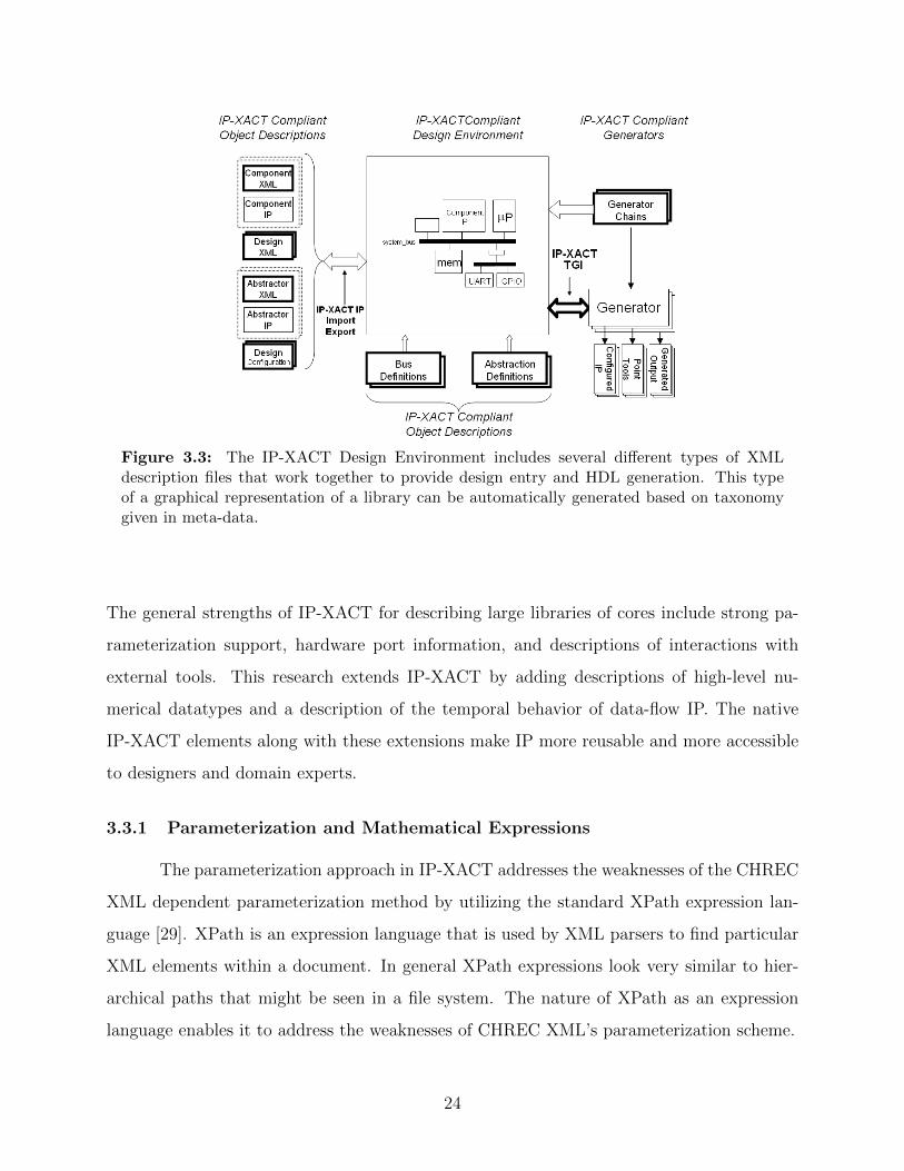
Figure 3.3: The IP-XACT Design Environment includes several different types of XMLdescription files that work together to provide design entry and HDL generation. This typeof a graphical representation of a library can be automatically generated based on taxonomygiven in meta-data.
The general strengths of IP-XACT for describing large libraries of cores include strong pa-
rameterization support, hardware port information, and descriptions of interactions with
external tools. This research extends IP-XACT by adding descriptions of high-level nu-
merical datatypes and a description of the temporal behavior of data-flow IP. The native
IP-XACT elements along with these extensions make IP more reusable and more accessible
to designers and domain experts.
3.3.1 Parameterization and Mathematical Expressions
The parameterization approach in IP-XACT addresses the weaknesses of the CHREC
XML dependent parameterization method by utilizing the standard XPath expression lan-
guage [29]. XPath is an expression language that is used by XML parsers to find particular
XML elements within a document. In general XPath expressions look very similar to hier-
archical paths that might be seen in a file system. The nature of XPath as an expression
language enables it to address the weaknesses of CHREC XML’s parameterization scheme.
24

1. XPath provides the ability to add an identification tag to any XML element. XML
validation tools enforce uniqueness on these tags. This uniqueness enables expressions
to reference variables based on their ID as defined in XPath and removes the need for
expressions to have their variables based solely on parameter names.
2. Because XPath defines syntax for expressions and because that syntax is meant to be
used in conjunction with XML documents, there are never collisions with XML syntax.
For example, instead of using > and < XPath uses > and <.
3. XPath provides a standard way for doing conditional expressions. These conditionals
are based on datatypes and use common operators such as “*” and “+” to determine
values based on conditionals. An example of this type of conditional in IP-XACT is
shown in XML 2. This expression means that if Sregsize ≥ 2 then the value should be
Sregsize else if Sregsize < 2 then the value should be 2. Although this representation
may not be immediately intuitive, it is standard and can be easily evaluated when
parsed by a tool.
XML 2 Definition of a dependent parameter value that is evaluated based on a high-levelparameter named Sregsize and has a default value of 2. This dependent parameter utilizesthe XPath expression language [29].<spirit:value spirit:resolve="dependent"
spirit:dependency=
"(id(’Sregsize’) >= 2) * id(’Sregsize’) + (id(’Sregsize’) < 2) * 2">2
</spirit:value>
3.3.2 Ports and Structural Interface
In addition to providing a standardized, robust, parameterization framework, IP-
XACT also provides information about the structural interface of a core. IP-XACT describes
the structural nature of the ports with several important elements: a name, a direction, a
width, and a low-level type.
25

Port Naming
IP-XACT defines several naming elements for ports. It defines a mapping between
the meta-data description of the port and the name in the actual HDL with the ‘‘display
name’’ and ‘‘name’’ elements.. The ‘‘display name’’ provides easy understanding to
the user. An extra description element is also provided. An example of the port naming
meta-data is shown in XML 3.
XML 3 A port description in IP-XACT. Elements of interest include naming and vectorelements as well as mathematical dependencies and low-level types.<spirit:port>
<spirit:name>preMu</spirit:name>
<spirit:displayName>Previous Mu</spirit:displayName>
<spirit:description>The value of mu from the previous iteration</spirit:description>
<spirit:wire>
<spirit:direction>in</spirit:direction>
<spirit:vector>
<spirit:left spirit:resolve="dependent"
spirit:dependency="id(’preMu_length’) - 1">18</spirit:left>
<spirit:right spirit:resolve="immediate">0</spirit:right>
</spirit:vector>
<spirit:wireTypeDefs>
<spirit:wireTypeDef>
<spirit:typeName>unsigned</spirit:typeName>
<spirit:typeDefinition>ieee.numeric_std.all</spirit:typeDefinition>
<spirit:viewNameRef>source</spirit:viewNameRef>
</spirit:wireTypeDef>
</spirit:wireTypeDefs>
</spirit:wire>
</spirit:port>
Port Direction
The direction of the port is essential when connecting IP together. Input ports must
be connected to output ports and vice versa. Is is also important that inputs are not driven
by multiple outputs. There is also the possibility of having bi-directional, in/out ports.
This information is especially important when attempting to enable automatic synthesis
26

and verification of point-to-point connections. IP-XACT provides this description in its port
description as shown in XML 3.
Port Widths
In addition to naming and direction, it is essential to know how many bits wide each
port is. Typical HDL is written at a level of abstraction that allows a single logical port
to contain multiple bits. This is also an appropriate level for representation in meta-data.
There are two basic pieces of information that need to be represented: the number of bits in
the port and which side of the port contains the most significant bit (MSB).
Both the number of bits and the MSB information is contained in IP-XACT in a
‘‘vector’’ element. The ‘‘vector’’ defines the left and right ends of the vector with an
integer. The greater of these two integers defines which end of the vector is the MSB and the
absolute width of the port is given by width = left-right. The values of left and right can
be parameterized to provide flexibility in implementation. An example of how port widths
are represented in IP-XACT is shown in XML 3.
Low-Level Types
For meta-data wrapping of certain types of HDL, the low-level type of the signal
is important. For example, if the IP being wrapped is VHDL, it is important to know
the VHDL bit vector type. It is important, for example to differentiate between a VHDL
std logic vector and a VHDL unsigned signal. This information allows connections to
be made with the proper VHDL or other low-level HDL types to ensure that a completed
system will compile and build properly. Not all core wrappers will require a low-level type,
but for typed HDLs this is appropriate to represent in meta-data.
3.3.3 Generator Chains
One of the primary advantages of using meta-data to encapsulate core details is that
cores from any source can be composed and manipulated in a common environment which
is aware of that meta-data. While this is a large advantage, if there is no way to compile
27

or convert the various IP into a common synthesizable language, the meta-data descriptions
and the accompanying environment are worthless.
IP-XACT addresses this need with “generator chains” as shown in Figure 3.3. A
generator chain in IP-XACT defines sequences of external tools that should be run in order
to convert IP from its HDL to a low-level standard format for implementation or simulation.
Each IP then can point to one or more tool chains. A single IP may be compatible with
several different generator chains depending on the end implementation. For example, a
generator chain for a piece of IP in VHDL that is intended for implementation on a Xilinx
FPGA might include tools such as XST, PAR, and Xilinx bit-gen. This particular chain also
defines commands to download a completed bit file to an FPGA device.
The overall goal of IP-XACT is to encapsulate IP in a vendor and implementation
neutral manner in order to facilitate reuse. System-on-Chip is the primary target for IP that
are supported by IP-XACT, which provides appropriate meta-data wrappers for this type of
design. Native IP-XACT allows SoC designs to be created from arbitrary IP in any language
from any environment and allows generic environments to be created to allow designers to
reason with these designs.
3.3.4 Modifying IP-XACT for FPGA IP
Because IP-XACT is designed to support SoC design, new methods are needed to
meet the description needs of arbitrary non-SoC IP for FPGAs. Two primary concerns
need to be addressed in this description. First, many designs that are typically targeted
to FPGAs consist of fine-grained IP. They do not tend to fit the SoC design paradigm but
tend to be data-flow designs such as DSP applications in which cores communicate through
computational data dependencies rather than communicating on a standard interconnect
bus [30]. Second, the increasing availability of FPGAs has driven the development of tools
that make FPGAs available to users without a digital hardware development background [15].
The SoC model is not suitable and may be too complex for simple use by many of these
domain experts. In order to make the computing power of FPGAs available to these domain
experts, reusable cores should be encapsulated in meta-data in such a way that they can be
easily used in a non-SoC system.
28

Both of these inadequacies in IP-XACT can be addressed by representing wrapped
IP at a higher level of abstraction using meta-data. The abstraction chosen for a particular
piece of IP should be appropriate to its intended use [31]. For many FPGA designs and cores
a DSP-compatible abstraction is appropriate.
Increasing design productivity by increasing abstraction is not new. The concept
of raising abstraction to increase productivity was also used when HDLs were originally
created [32]. Before HDL, schematic capture was used and designers often had to work at
a very low level, sometimes having to design with individual transistors. With HDL came
the ability to synthesize logic from a higher-level description without having to manually
construct the logic. The concept of raising abstraction to increase productivity can be
applied to existing HDL IP with proper meta-data wrappers.
The meta-data that is included in basic IP-XACT is fundamentally structural in its
encapsulation approach and does not significantly increase abstraction over a standard HDL
description. The structural description provided by IP-XACT can be supplemented and
expanded by using IP-XACT as a base description and adding high-level datatypes and
temporal behavior information as extensions to the schema. These additional description
elements are similar to those that were originally represented in CHREC XML and provide
a method of raising the abstraction level through encapsulation and are easily applied to
common FPGA IP used for data-flow computation.
3.3.5 Extensions for High-Level Datatypes
Many data-flow FPGA IP communicate numerical data. A difficulty with the IP-
XACT representation of ports is that it does not reflect this higher-level data typing. If
datatypes are nor represented, data corruption can occur between cores when only bit-widths
are required to match on connected ports. Figure 3.4 shows an example of this problem.
Here two 16-bit ports are connected to each other and the most and least significant bits are
properly aligned. However, by naively connecting these ports by bitwidth only, there has
been a data corruption; the 5.9124 that was transmitted has been interpreted as a 4.4781.
This problem becomes more pronounced when floating point or other complex types are
used. In order to ensure correctness of data transfer between cores with arbitrary interfaces
29

and to avoid the problem caused by naive bitwidth-only connections, higher-level datatypes
should be associated with port bit-vectors.
Figure 3.4: The two fixed-point numbers shown have the same bitwidth; however, if only thebitwidths are matched the data transferred between these types will be incorrectly interpreted.
This work extends the IP-XACT standard to include several numerical and other
high-level types that can be associated with signals. This research proposes meta-data
descriptions for bit vector, integer, fixed point, floating point, and custom datatypes. These
types are briefly discussed here and described in detail in Appendix A.
Bit Vector: Bit Vector types have no associated numerical data and are simply
represented as a vector of bits.
Integer: This datatype is basic for standard integer representations of any bitwidth.
It can describe unsigned, 1’s compliment, 2’s compliment, and signed magnitude integer
types.
Fixed Point: This type defines either a number of integer bits or a number of
fractional bits to be included. The total distribution of bits between integer and fractional
bits can be determined from either of these along with the entire bitwidth of the signal. All
of the cores used in the radios built in this study utilize the fixed point representation.
Floating Point: This datatype is highly parameterizable to represent possible divi-
sions of bits in floating point number representations. The floating point type is similar to
the IEEE standard for floating point representations. It has three fields, {1 sign bit}{k bits
for exponent}{n bits for fraction of significand} which can be arbitrarily mapped to bits in
the underlying signal.
Custom Types: Custom types contain a list of fields which associate a name and a
sub-vector of bits from the underlying bit representation.
30

These datatypes are used in the architectural synthesis tool presented in chapter 5 to
ensure that data transfer between cores is correct.
3.3.6 Extensions for Temporal Interface Behavior
Because IP-XACT was originally intended to describe IP that is used in SoC systems,
it does not have a mechanism for describing the temporal behavior of IP interfaces. There
are many ways of representing these interfaces and several methods have been developed
for representing IP interfaces mathematically. Finite automata, both deterministic (DFA)
and nondeterministic (NFA), have been used to describe the protocol and timing behavior of
cores with handshaking protocols which interface with various bus protocols. Several of these
include those discussed in [33], [34], [35], [36], [37], [38], and [9]. While these specifications
are important to many types of IP, they do not meet the requirements of data-flow DSP
and FPGA IP which tend to be data-driven pipelined computational cores and often do not
have handshaking type protocols. An attempt at creating an automata-based description for
DSP IP is given in Appendix B; however, there has not yet been an attempt to implement
this description or to describe it in meta-data.
This work attempts to match the temporal interface behavior of data-flow IP for
FPGAs to the homogeneous synchronous dataflow (H-SDF) model of computation. This is
done by defining three extensions to IP-XACT that allow IP to be described as actors in an
H-SDF graph. These parameters are latency, data introduction interval, and sample delay.
These parameters are important in creating a synthesis system that is able to apply archi-
tectural synthesis algorithms to systems composed of coarse-grain IP. A complete discussion
of these parameters and their use in architectural synthesis is given in chapter 5.
The meta-data formats described in this section, both CHREC XML and IP-XACT
with extensions, propose a standard way of representing meta-data to describe data-flow
FPGA IP. Because meta-data is important to reuse, it is helpful to have a standard way of
representing that meta-data. A standard mechanism enables tools to be built that can work
with the standard and thereby expand the number of IP that are reusable in a tool to all
IP that are described in this standard way. The following chapters will address such tools.
Chapter 4 will present a structural design tool and a parameterization manipulation interface
31

based on CHREC XML that demonstrate the use of standard meta-data. Chapter 5 will
present a different tool called Ogre that utilized IP-XACT and the high-level extensions to
enable architectural synthesis.
32

Chapter 4
Meta-Data Enabled Design Environment
This chapter presents a structural design tool that demonstrates the ability of the
meta-data developed in this work to represent the structural interface of FPGA IP in a
language and source independent manner. This tool enables IP cores from any language to
be instanced and connected independently of their underlying representation.
In addition to the ability to structurally interconnect cores, this tool demonstrates
the ability of meta-data to represent parameterization and the interdependency of param-
eters in IP in a standard way. The parameterization manipulation interface presented in
section 4.2 leverages meta-data descriptions to automatically create a custom parameteriza-
tion interface for individual IP. This GUI demonstrates the usage of parameter relationships
via mathematical expressions by automatically adjusting parameter values and the graphical
representation of the IP when a user makes adjustment to parameter values. This structural
design tool is based primarily on concepts developed in CHREC XML. However, the meta-
data enabled techniques demonstrated in this chapter can also be accomplished by leveraging
IP-XACT and the extensions contributed by this work.
4.1 A Structural Design GUI
Meta-data that defines a standard IP naming scheme and that represents the basic
structural interface of IP can be used as the basis for a language and IP source independent
design composition tool. To enable IP reuse, meta-data can define standard naming methods
that enable a designer to rapidly find desired IP. All hardware IP have common elements
in their structural interface. When these elements are represented in standard meta-data, a
tool can use these elements to represent IP to a designer in a language independent manner.
33

Meta-data can also enable design composition by defining the structural nature of IP input
and output ports.
In addition to enabling language and source independent representation of libraries
of IP, CHREC XML also enabled the building of a generic structural design tool. This
tool allowed a designer to structurally interconnect IP from the library and automatically
generate bitstreams for download to an FPGA. The structural interconnection of IP and the
use of tools to create completed, downloadable designs were enabled by meta-data.
The general flow for this structural design tool is shown in Figure 4.1. IP in any
language could be imported into the library. For VHDL cores, this research developed a
parser that automatically created much of the CHREC XML meta-data that was required
for representation in the library. Once this basic XML was created by the parser, the user
was prompted to add extra information not contained in HDL but required for a complete
CHREC XML description.
Figure 4.1: The CHREC XML schema supported a library structure, allowed for basic com-position of IP, and allowed appropriate vendor tools to be automatically run as generators onIP. The XML also enabled automatic generation of wrappers for the created core in multiplecommon languages.
34

Once IP was imported into the library, the CHREC XML meta-data allowed this
IP to be dragged and dropped onto a design canvas where their ports were connected as
shown in Figure 4.2. The graphical representation for the IP on the design canvas was
automatically generated by the tool based on the meta-data descriptions. The XML was
queried to determine the names and widths of the input and output ports and the graphical
representation was created based on this data. Because the GUI’s representation of cores
depended only on the meta-data in XML, any IP represented in XML could be used in this
structural composition GUI.
Figure 4.2: The GUI tool demonstrates the ability of CHREC XML to standardize descrip-tions for cores from multiple environments and enable them to communicate. The two matchedfilters in this design are from Xilinx CoreGen and the PLL circuit from JHDL.
35

Figure 4.2 shows the structural design of part of a QPSK demodulator in the composi-
tion GUI. This QPSK fragment used two filter circuits generated by the Xilinx CoreGen tool
and a PLL circuit created from JHDL. Because of the different representation languages and
sources of these IP, connecting them in a design would normally require significant manual
manipulation. However, because of the meta-data wrappers defined in CHREC XML, the
composition of these cores could be achieved in a straight forward manner. Once cores were
instanced in the GUI, each core icon showed the ports and the tool allowed the designer to
parameterize the cores (if parameters exist) and to connect ports graphically.
Once the designer had connected the cores in the GUI as desired, the entire design
could be synthesized and a downloadable bitstream created automatically. This was done
based on the file sets and the external tools that were defined as generators in CHREC
XML as shown in Figure 4.1. For the IP in the QPSK segment shown in Figure 4.2, the
Xilinx CoreGen tools were automatically run to create an EDIF version of the filter circuits.
The JHDL compilation tools were run to create a structural VHDL representation of the
PLL. These two cores were automatically instanced and connected in a top-level VHDL
file and this VHDL was then passed by the tool to the Xilinx tool chain. The tool issued
the commands to Xilinx to synthesize, place and route the design and generate a complete
bitstream.
The language and source independent design environment was enabled by meta-data
in CHREC XML. The meta-data enabled a standard representation of libraries of IP and
allowed that library to be easily searched. Structural composition of IP was also enabled by
the meta-data that allowed the design environment to represent IP graphically regardless of
its implementation language or source environment. While these demonstrations are simple,
they show the ability of meta-data to enable tools to organize IP from different sources into a
new design. Other tools could also be created that leverage the meta-data in CHREC XML.
One such tool that performs architectural synthesis based on IP described in meta-data will
be presented in Chapter 5.
36

4.2 Parameter Representation and Manipulation
In addition to providing the ability to structurally interconnect IP in a graphical envi-
ronment, the structural design environment also enabled core parameters to be manipulated
in a generic GUI. Because reusable IP tends to be highly parameterized, it is important to
be able to correctly set parameter values [19]. Two types of parameters were represented
in CHREC XML and in IP-XACT with extensions. Traditional low-level parameters such
as those traditionally included in HDL were listed in XML. Higher-level, domain specific
parameters that did no exist on the original HDL were also listed. Mathematical expres-
sions enabled the tool to set low-level parameters based on higher-level parameter values.
This section discusses the concepts of low-level parameterization, high-level parameteriza-
tion, the translation between levels enabled by mathematical expressions, and the parameter
manipulation GUI that utilized these types of parameterizations.
4.2.1 Traditional Low-Level Parameterization
Hardware cores have traditionally been parameterized with low-level parameters such
as bit-widths and operating modes which are typically represented in HDL. These param-
eters describe relatively low-level changes that can be applied to the core. This low-level
parameterization increases the reusability of a core by allowing it to be used in designs that
require different bit-widths. Low-level parameters typically defined by a name-value pair.
Their values typically have little or no direct dependency or affect on other parameters. Low-
level parameterization is quite common and is fairly simple to implement and meta-data can
represent this type of parameterization quite simply.
Traditional parameterization can significantly increase IP reusability for experienced
hardware designers; however, this low-level, HDL parameterization can be difficult to under-
stand and use for a non-hardware expert. Even experienced hardware designers still have to
understand the low-level implementation of the core in order to integrate it properly into a
system even when the IP has extensive low-level parameterization on a core. The designer
must understand how each of the parameters affects the other parameters and the core’s
behavior. Extensive low-level parameterization presents a greater challenge to a domain ex-
pert, the domain expert may be more confused by a highly parameterized core that has only
37
low-level parameterization. For example, a core with several parameterizable bit-widths that
the designer must manually select without a knowledge of how these will affect the operation
of the IP may be less attractive than a core with no parameterization at all [19].
4.2.2 High-Level Parameterization
Encapsulating low-level parameters in higher-level, more domain specific parameters
can further increase the reusability of cores without causing user confusion. Meta-data
can be used to create high-level parameters that did not exist in the original HDL but
which are more applicable and understandable to a particular domain. For example, for
IP for digital communication systems, high-level parameters that are readily understood by
communication systems experts could be defined. These high-level parameters allow the
designer to interact with the core at a higher level of abstraction and therefore increase the
reusability of the core. This reusability can also be realized both for the experienced hardware
designer and for the inexperienced domain expert. The need for experienced designers to
manipulate the low level details is removed and the ability of the domain expert to understand
the operation of the core is increased because the parameters are more familiar.
Examples of high-level parameters are shown in the Table 4.1 for a typical loop filter
core from the communications IP library developed in this work [39]. This is a simple
first-order loop filter consisting of a multiplier and an accumulator. This core has low-level
parameters for signal bit-widths and constant multiplication coefficients; however, high-level
parameters specific to communication receivers are presented in the meta-data wrapper. The
parameters shown in Table 4.1 are used to perform a non-trivial calculation which determines
both bit-widths and coefficients necessary for a given signal processing function.
In addition, this core contains a parameter named ‘‘samplesPerSymbol’’, which
allows the core to be quickly used in different radio personalities that each operate on a
different number of samples for each output symbol computed. Changing this parameter
fundamentally changes the core’s internal behavior and structure. This high level of param-
eterization significantly improves the ease of reuse for this IP by allowing users to quickly
adapt it to a number of similar but significantly different designs.
38

Table 4.1: High-level parameterization for loop filter core.
Parameter DescriptionloopBandwidth BnT used in calculating constant multiplicand valuesloopDampingFactor ζ used in calculating constant multiplicand valuesphaseDetectorGain Kp used in calculating constant multiplicand valuesaccumulationWidth Number of bits right of radix point for internal accumulatorkPrecision Number of fractional bits used for constant multiplicand valuesddsGain K0 used in calculating constant multiplicand valuessamplesPerSymbol Norder Loop order: first (no accumulator) or second (with accumulation)
4.2.3 Parameter Dependencies and Translation
Because not all IP is designed with high-level parameters, reusability can be improved
by providing a mechanism for enabling IP with robust low-level parameterization to be
parameterized at a high level in a meta-data wrapper. Once high-level parameters have
been set in meta-data they can be translated to more traditional, low-level parameters as
shown in Figure 4.3. High-level parameters can exist in meta-data alone and the meta-
data description itself can describe the relationship between derived high-level parameters
and actual low-level parameters on the IP. This type of dependency is supported by both
CHREC XML and IP-XACT which both provide mathematical dependency relationships
between parameters values.
Meta-data can be used to compute lower level parameters based on the higher-level
parameters defined exclusively in meta-data. For example, if low-level parameters for the
bitwidth of a core are available in HDL, meta-data wrapping that IP could present the user
with a parameter that asked for the minimum and maximum values expected by the IP. The
meta data could then define the mathematical relationship between this given parameter
range and the proper bitwidth parameter that should be set. The ability to parameterized
exclusively in meta-data allows higher-level parameters to be created that did not originally
exist for a core.
The encapsulation of complex, low-level parameters in higher level parameters and
accompanying mathematical relationships reduces the number of unique parameters that
39

Figure 4.3: The high-level parameters represented only in meta-data can be translated toexisting low-level, HDL parameters using mathematical and dependency relationships betweenparameters.
must be set by the user, while still allowing for powerful, deep parameterization. It should
be noted here that not all of the dependencies between high- and low-level parameters must
be expressed in meta-data—VHDL functions (in corresponding core module generators) may
also be leveraged for the computation of some low-level parameters.
Because IP can be extensively parameterized it is important for meta-data descrip-
tions to robustly support this parameterization. The meta-data developed in this work, both
CHREC XML and extended IP-XACT, supports parameterization. Both low- and high-level
parameters can be described in meta-data. The meta-data also describes the relationship
between these parameters methematically and allows higher-level parameters to be defined
exclusively in meta-data and be translated into low-level parameters.
4.2.4 A Parameter Manipulation GUI
A parameter manipulation GUI was created to demonstrate the ability of the CHREC
XML meta-data to represent parameters. The parameterization of IP used in this GUI was
often complicated with some IP having many interrelating parameters. Because of the meta-
data, the parameter manipulation tool was able to automatically set and correct parameter
40

values based on mathematical expressions was demonstrated by the parameter manipulation
GUI.
Figure 4.4: Each core instance can be individually opened and its parameters modified to fitit to a particular use. The parameterization manipulation window is automatically generatedon the fly from the meta-data descriptions.
The parameter manipulation GUI was generated on the fly from meta-data describing
IP that had been instanced in the structural design tool. After an instance had been created
for a core as shown in the GUI in Figure 4.2, the designer could “open” an individual instan-
41

tiated core and edit that core’s parameters as shown in Figure 4.4. The parameterization
interface shown in Figure 4.4 is the FIR filter that was used in the QPSK segment shown in
Figure 4.2.
Meta-data was leveraged to generate the left panel of the GUI shown in Figure 4.4.
This panel displayed the different parameters that could be changed by the user. The pa-
rameter names and their default values were extracted from the meta-data and appropriately
represented on the parameter panel. The GUI presented only the high-level parameters that
should be set by the user; all others were automatically calculated and set as defined in
XML.
The meta-data also enabled the tools to correctly represent the parameter input
method. Some parameter values could be typed in a field, while others required selecting
a value from a drop-down menu. This reflected the definition of valid parameter values as
defined in meta-data. In CHREC XML some parameters were allowed to fall in a given range
of numerical values. Other parameter values were to be selected from a set of choices. These
value types were reflected in the manipulation GUI with ranged numerical values being input
via a field and choices via a combo-box.
The mathematical expressions defined in meta-data were used by the GUI to ensure
proper parameterization of the IP. When users manipulated parameter values, the GUI
responded to these manipulations by altering other parameter values to ensure a valid core
parameterization. For example, when setting the parameters for the FIR filter shown in
Figure 4.4, if the value of the parameter CSETPassbandMin changed, then the minimum
valid value for the parameter passband max also changed. If the user had already set a value
for this parameter that is now outside of the valid range, the GUI corrected that value to
be within the range and notified the user. Other parameters that were dependent on user-
set parameters were also modified as the user changed the parameter values. Parameters
in some IP, especially IP from Xilinx CoreGen [17], affected which ports would exist on a
particular IP when it was generated. When these parameters were changed in the GUI, the
representation in the right panel of the GUI changed to reflect these changes. This right
pane also reflected changes in bitwidths of signals as parameter values changed.
42

The ability of the parameter manipulation GUI to represent parameters was based
solely on meta-data from CHREC XML. None of the manipulation GUI was specific to any
particular IP. The parameterization of IP from any hardware description language or IP
generated by a tool could be represented in this GUI because it depended on meta-data.
The GUI was able to update parameter values and change the graphical representation of
the IP because of the mathematical parameter relationships in CHREC XML. This type of
HDL-independent parameter manipulation is important to describing large libraries of IP
from different sources because it provides a common method for setting parameters based
on mathematical relationships described in meta-data.
4.3 Language-Specific Wrapper Generation
In addition to manipulation of parameters, the CHREC XML meta-data enabled the
tool to create custom wrappers for a single piece of IP and composed designs in a variety
of languages. The structural design tool allowed the designer to export this particular IP
with its parameterization in a VHDL, Verilog, or EDIF wrapper. The generation of wrap-
pers in multiple languages demonstrated the ability of the meta-data to represent sufficient
information to duplicate the interface of an IP core in any language.
Wrapper generation was performed by by querying the XML for port data and using
this data to create a proper wrapper in different languages. If the IP described in XML
had parameters, the tool was able to use this meta-data to properly set the parameters in
the appropriate wrapper languages. The tool also allowed the designer to export a CHREC
XML file that contained the current parameterization for a particular core and allowed the
designer to change the naming of the IP to reflect any customization that may have been
made. The generation of wrappers and the ability to export the core in several formats
all depended on the meta-data in CHREC XML. This meta-data allowed tools to generate
wrappers and run tools regardless of the original implementation language because all needed
data was encapsulated in the XML.
Meta-data enabled design composition and parameter manipulation in a language
independent manner. The tool presented in this chapter leveraged the CHREC XML de-
scriptions of IP to enable structural composition of IP. The graphical representation of cores
43

in the GUI was generated based on the XML descriptions. CHREC XML meta-data also
enabled the automatic generation of top level design VHDL and synthesis of complete de-
signs to bitstreams by automatically running vendor tools specific to different pieces of IP
in the design. Manipulation of parameters was also enabled by meta-data. The parameter
manipulation interface was generated based on meta-data descriptions and the mathemat-
ical dependencies in CHREC XML enabled the GUI to enforce validity of parameter sets.
Meta-data was the key factor in enabling these language- and source-independent design
methods.
44

Chapter 5
Meta-Data Enabled H-SDF Synthesis Using IP
As demonstrated in Chapter 4, it is relatively easy to instance, specialize (i.e., set
parameters), and connect arbitrary IP that is described using XML-based meta-data. This
type of structural design was simple because all of the data required to perform these tasks
was readily available in XML. This chapter introduces another tool that can compose FPGA
designs based on XML IP. This tool, however, operates at a higher level of abstraction and
uses meta-data to reason about correctness of data transfer between connected IP and to
automatically synthesize control circuitry for dataflow designs in FPGAs.
Traditionally control synthesis systems have used fine-grain IP such as multipliers and
adders as its primitive operators. When more coarse-grain IP have been used for synthesis,
the set of possible IP was often limited to a small set of IP that is native to the synthesis
tool. This work, however, allows any coarse-grain IP that is described in meta-data to be
used in synthesis thus allowing the set of operations for synthesis to include any arbitrary
IP from any source.
The addition of two primary types of information to a meta-data description for
FPGA IP were required for the construction of this synthesis tool: high-level numeri-
cal datatypes and temporal behavior specifications. Meta-data for high-level numerical
datatypes describes the datatypes that are represented on input and output ports for IP. This
information enables tools to assist a designer in ensuring that datatypes are correctly ma-
nipulated as data flows through a design. Meta-data specifying the temporal behavior of IP
allows tools to automatically synthesize control circuitry that enforces the proper sequences
of IP operation and ensures that no data is lost in communication.
This chapter will introduce a design tool known as Ogre that uses datatype and
temporal behavior specifications in meta-data to enable the synthesis of dataflow systems.
45

Figure 5.1: An overview of the Ogre System. There are four primary components: libraryrepresentation, translation of schematic information to H-SDF graphs, scheduling the H-SDFgraph, and synthesizing control and interface circuitry to create a complete downloadablebitstream.
The general flow of the Ogre system is shown in Figure 5.1. Ogre utilizes the Simulink
GUI and model file to represent models of systems composed of reusable IP as shown in
Figure 5.2. These models are understood by the underlying synthesis system which can then
reason about high-level datatypes and synthesize control circuitry. This chapter will discuss
the use of high-level datatypes to help a user properly match datatypes between IP in Ogre.
It will also present the method used by Ogre to leverage the H-SDF model of computation to
schedule IP operation and synthesize control and interface circuitry by leveraging meta-data
descriptions.
46

Figure 5.2: Simulink is used as a front end for design entry by the Ogre tool. IP blocksdescribed in IP-XACT XML are automatically included in a Simulink library and can bedropped onto the simulink design pallet to create complete designs.
5.1 Numerical Datatypes
The Ogre tool used high-level numerical datatypes to check for valid data transfer
between IP that have been connected in a design. Much of the IP that is used in data-
flow designs for FPGA operates on numerical data. Because of this, signals in data-flow
computations are also often meant to be interpreted as some type of number such as an
integer or a fractional number represented as fixed or floating point. When composing data-
flow designs and attempting to reuse IP, it is vital to know the mapping of bits in a signal
to the numerical data being represented by this signal. If this mapping data is not available,
blindly tying cores together will almost certainly result in incorrect data transmission. This
is especially important when working with fractional numbers and their fixed and floating
point representations. Ogre utilized the meta-data descriptions developed as extensions to
47

IP-XACT which define a standard way of mapping high-level datatypes to their underlying
bit-vector implementations.
5.1.1 Representing Datatypes
The extension to IP-XACT that allows for the representation of datatypes defines
mappings between high-level datatypes and the bits that implement those types on a partic-
ular signal. There are two components to this representation: the definition of the underlying
bit-vector and the mapping of these bits to a high-level type.
The bit-vector representation is contained in the meta-data description of each port
in XML. The port is defined by the XML ‘‘vector’’ element with the width of the port
being defined as the left side of the vector minus the right side of the vector (left− right).
XML 4 This code snippet shows an example of a high-level datatype extension. Thisexample shows a signed fixed-point type where two bits are used to represent the integerpart.<spirit:component>
. . .
<spirit:vendorExtensions>
<chrec:highLevelDataTypes>
<chrec:portDataType>
<chrec:name>SFix_2_a</chrec:name>
<chrec:fixedPoint
chrec:sign="2sComplement">
<chrec:intBits chrec:resolve="static">
2
</chrec:intBits>
</chrec:fixedPoint>
</chrec:portDataType>
</chrec:highLevelDataTypes>
. . .
</spirit:vendorExtensions>
. . .
</spirit:component>
The high-level type is defined separately from the description of the port. Each port
points to the high-level type that should be used to represent it allowing multiple ports to
be defined by the same type without the need to duplicate the description of the type. An
48

example of a high-level type definition is shown in XML 4. This particular definition is for
a fixed-point datatype. It defines that the two most significant bits should be interpreted as
integer bits and the rest of the bits of a signal should be interpreted as fractional bits. For
fixed-point datatypes it is also possible to specify the number of fractional bits that should
exist on a signal and assume that the rest are integer bits. The extensions to IP-XACT for
datatypes and the details of their implementation are discussed at length in Appendix A
and in [39].
5.1.2 Utilizing Numerical Types
The IP-XACT extensions developed in this research that describe high-level types
were used in the Ogre design synthesis system to assist designers in ensuring that datatypes
matched between IP. Ogre ensures first that bitwidths between IP match and then checks the
datatypes of these connections. If there is a mismatch, Ogre alerts the user to the problem.
Before Ogre checks data-types, Ogre first ensures that bitwidths match between IP.
Bitwidth matching is done by performing a traversal of the diagram starting at the inputs
and propagating the input bitwidths through the design. Mathematical relationships between
parameters and port widths enable the tool to properly set parameters to make bitwidths
match between IP. Once all bitwidth matching has been done, the tool iterates over all nets
in the design and checks that the high-level datatypes are compatible between the ports on
that net. If one of the ports does not match the others, an error is reported to the user,
advising the user of which net had the offending port.
Although the functionality of Ogre leveraged high-level types only for checking of
proper data connections, these meta-data defined types provide the ability for a tool to per-
form more sophisticated datatype synthesis. For example, a tool could leverage the datatypes
in meta-data to automatically synthesize datatype conversions between IP when it detects
that there is a datatype mismatch. When a tool detects a mismatch, a parameterized block
of IP could be inserted between the incompatible ports, making their datatypes compatible
as shown in Figure 5.3.
The high-level datatypes developed in this work are essential for any tool that will
automatically compose cores for data-flow designs on FPGAs. If the high-level numerical
49

Figure 5.3: Datatype-aware tools can use high-level datatype information to synthesize con-version logic between incompatible datatypes and thereby ensure correct data transmission.
datatypes are not defined, there will most likely be corruption of data as it moves between IP
in a design. The meta-data high-level types included in CHREC XML and in extensions to
IP-XACT provide the necessary mapping between the bits of an IP port and the high-level
type which that port’s data belongs to.
5.2 Representing Coarse-Grained IP as H-SDF Actors
In order to automatically compose arbitrary IP in a dataflow system, a description
of the timing behavior of the IP’s interface is required. If temporal core behavior for IP can
be matched to a particular model of computation, tools will be able to reason with these
cores and automatically generate control circuitry for designs. The meta-data proposed in
this work to describe timing behavior is based on the homogeneous synchronous dataflow
(H-SDF) model of computation [40]. This section will briefly describe the H-SDF model and
describe how meta-data implemented as extensions to IP-XACT enabled cores to be mapped
as H-SDF actors.
5.2.1 The H-SDF Model of Computation
The H-SDF model of computation defines the execution semantics for a system based
on the dataflow relationships between portions of the system. H-SDF is represented by a
50

directed, vertex weighted, graph G = {V,E}. Each vertex v ∈ V is called an H-SDF actor
and each edge (x, y) ∈ E represents the operation precedence between two actors.
The edges in E are used to enforce execution semantics on the H-SDF graph. For
example, the presence of edge (a, b) in G means that all computation must be done in vertex
a before vertex b can start its computation. Computation in H-SDF is done by the actors.
When an an actor performs a computation, it is said that the actor “fires.” The weight of
the vertex v represents the number of steps required for that particular actor to fire.
In addition to simply defining edges between vertices, H-SDF also uses the notion of
tokens to enforce semantics. Each edge in G can contain multiple tokens at any given time.
In order for any actor in H-SDF to “fire,” or perform computations, it must have an input
token on each of its inputs. If there are no input edges to an actor, it may fire at any time.
When an actor “fires” it produces tokens on all of its output edges.
(a) Actors A and B fire and pro-duce tokens on outgoing edges.
(b) Actor C fires consuming allinput tokens and producing anoutput token on outgoing edges.
(c) Actor D fires and consumesall inputs. Computation is nowfinished.
Figure 5.4: The homogeneous synchronous dataflow model of computation allows each nodeto “fire” when one token is available on each of its inputs. Each firing produces one token onthe node’s output.
Homogeneous synchronous dataflow is a subset of standard synchronous dataflow
(SDF) because when H-SDF actors “fire” they consume only one token from their inputs
and produce one token on their outputs. In general SDF, actors are allowed to consume and
produce multiple tokens when they fire(i.e., multi-rate dataflow). In this work H-SDF was
51

chosen as the model of computation because many single-rate systems can be represented
as actors that consume and produce single tokens when they perform computations. H-SDF
was also chosen because it is easier to use than general SDF.
Figure 5.4 shows an example of an H-SDF model and a valid sequence of actors firing.
Because actors A and B have no inputs they can fire at any time. When they fire, they each
produce tokens on their output edges. Actor C is allowed to fire once tokens produced by A
and B are both present on its inputs. When C fires, it also produces a single output token
which is consumed by actor D when it fires. Actor D’s firing completes a valid computation
from this H-SDF model.
(a) Invalid H-SDF initialconditions
(b) Valid H-SDF initial con-dition with one initial tokenin the loop
(c) Valid H-SDF initial con-dition with two tokens in theloop
Figure 5.5: A cyclic H-SDF graph must have proper initial conditions. Each cycle in the graphmust start with at least one token already on an edge in the cycle. The graph in figure 5.5(a) isinvalid because it has no such initial condition. Figure 5.5(b) shows the simple case of a validinitial condition with one token initially in the loop. Multiple initial tokens are valid as shownin Figure 5.5(c).
The H-SDF model of computation also supports cyclic data dependency graphs. How-
ever, when an H-SDF graph is cyclic, care must be taken to correctly satisfy the initial con-
ditions for the computation. For each cycle in an H-SDF graph there must be at least one
token on an edge in that cycle. If there is no token in the cycle, the computation will not
be able to start because no actor will have the needed inputs. Multiple tokens may exist in
the cycle or even on a single edge, but at least one token must be in the cycle. An example
of proper and improper initialization of H-SDF graphs is shown in Figure 5.5.
52

The execution semantics of H-SDF allow a static schedule to be computed for the
graph. This schedule will be a repeating schedule that defines the relative start times for
each of the actors. When using H-SDF to represent hardware systems, the schedule can be
mapped on to clock cycles for pipelined IP.
Because H-SDF enforces execution semantics on a dataflow graph, it is useful in
describing the execution of single-rate dataflow systems for FPGAs. If each IP core in a
system can be interpreted as an actor using H-SDF semantics, then the execution semantics
of H-SDF can be used to determine how the hardware system should execute by creating
a static schedule for the operation of IP in the system. This research defines three meta-
data elements that allow coarse-grain IP to be described in a way that allows them to be
interpreted as actors onto the H-SDF graph. This meta-data defines the latency, the data
introduction interval, and the sample delay for IP.
5.2.2 Latency
The latency of an IP core is the number of clock cycles that elapse from the time that
data is consumed on the inputs of the core to the time that the corresponding results are
produced on the outputs. This does not mean that the core is pipelined in the traditional
sense or that data can be accepted by the core on every cycle. For example, cores that accept
data only every 8 cycles and take 9 cycles to compute a result would be given a latency value
of 9.
When mapping a IP core onto an H-SDF actor the latency of IP is represented in
H-SDF graph by the weight of an actor. Because this weight defines the amount of time that
elapses while an actor is performing a computation, this weight can interpreted as the number
of latency clock cycles. This information can be used by H-SDF scheduling algorithms to
to determine the time that data will appear on the output of a core. The latency can also
allow synthesis algorithms to appropriately control IP downstream to wait until valid data
has been produced by the IP.
53

5.2.3 Data Introduction Interval
The data introduction interval for a core describes how many clock cycles must elapse
between the introduction of data for each new sample. Cores with a data introduction interval
of one can accept new samples each clock cycle. The data introduction interval of a core is
independent of its latency. For example a core that has a data introduction interval of 3 can
consume data on clock cycle 0 but then will not consume data again until clock cycle 3 and
then again on cycle 6. This same core may take 9 cycles to compute a result from a set of
inputs.
The data introduction interval imposes an additional constraint on the scheduling
algorithms that generate control for H-SDF execution. If tools are aware that a core can
only accept new data every n clock cycles, then any synthesized control circuitry must ensure
that data is given to a core only when it is able to receive it.
5.2.4 Sample Delay
Sample delay is perhaps the most complected parameter used to describe IP as H-
SDF actors. The sample delay is the number of cycle iterations separating an actor from the
downstream actors. In other words, the sample delay defines how many cycle iterations later
the data produced by an IP will be needed for computation. Sample delay is important when
IP are going to be used in a cyclic manner. For example, in the design shown in Figure 5.2
there is a cycle in the design. The sample delay defines the break between iterations of the
cycle.
Sample delay can also be thought of as the number of initial tokens in a cycle in an
H-SDF graph. If we consider a design to be represented as a H-SDF graph, we know that
there must be at least one initial token on an edge in the cycle in order to enable this loop to
execute properly according to H-SDF semantics. It is this initial condition that the sample
delay represents.The sample delay parameter indicates the number of H-SDF initial tokens
existing on the outputs of a particular IP.
Another way to conceptualize sample delay is that it represents the state generated
by the previous iteration of the loop. For example in Figure 5.5(b) the token that exists on
54

the arc ~ba represents the result of the computation done by the previous execution sequence
{a, c, b}.
This research chose to represent sample delay as a property of a piece of IP. While the
proper way of representing sample delay in cyclic models is an open research question, there
are several advantages to representing it as a property of a particular IP block. Representing
sample delay as a property of a block of IP is especially useful when IP cores are used
in situations that are closely related to their original design. When the sample delay is a
property of particular communications IP, for example, these blocks need only be inserted in a
cycle and the sample delay of that cycle is automatically satisfied. This type of representation
is also logical when thinking of sample delay simply as the state from the previous iteration
of the cycle. If the IP with the sample delay also has internal registers to maintain state,
these registers contain the result of all upstream computation in the cycle. This type of
representation, however, is now without its weaknesses. It breaks down if a core is used in a
situation that is not similar to its original use. This may cause the sample delay on the IP
to be in an incorrect location.
The demonstration avenue for these techniques was communication systems. IP that
are defined to have sample delay in these communication systems are rarely if ever used in
a situation different from their initial usage. There may be models, however, that require a
computation cycle but do not have any IP with an implicit sample delay. For this purpose, a
sample-delay marker that could be used in Simulink models was also created in this research.
5.2.5 IP-XACT Extensions for H-SDF
The meta-data description elements needed to represent coarse-grain IP as actors in
H-SDF was implemented as a set of XML elements called the ‘‘behavioral layer’’. This
set of elements was added to IP-XACT as a vendor extension. XML 5 shows the definition
of a temporal H-SDF interface as it appears as an IP-XACT extension. This particular
interface has a data introduction interval of 7, a pipeline depth of 8, and a sample delay of
0. This representation method allows sample delay to be represented as part of the IP core
and does not require the user to understand the complex concept of sample delay.
55
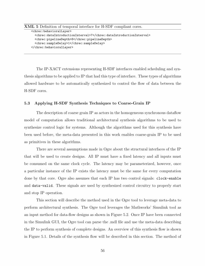
XML 5 Definition of temporal interface for H-SDF compliant cores.<chrec:behavioralLayer>
<chrec:dataIntroductionInterval>7</chrec:dataIntroductionInterval>
<chrec:pipelineDepth>8</chrec:pipelineDepth>
<chrec:sampleDelay>1</chrec:sampleDelay>
</chrec:behavioralLayer>
The IP-XACT extensions representing H-SDF interfaces enabled scheduling and syn-
thesis algorithms to be applied to IP that had this type of interface. These types of algorithms
allowed hardware to be automatically synthesized to control the flow of data between the
H-SDF cores.
5.3 Applying H-SDF Synthesis Techniques to Coarse-Grain IP
The description of coarse grain IP as actors in the homogeneous synchronous dataflow
model of computation allows traditional architectural synthesis algorithms to be used to
synthesize control logic for systems. Although the algorithms used for this synthesis have
been used before, the meta-data presented in this work enables coarse-grain IP to be used
as primitives in these algorithms.
There are several assumptions made in Ogre about the structural interfaces of the IP
that will be used to create designs. All IP must have a fixed latency and all inputs must
be consumed on the same clock cycle. The latency may be parameterized, however, once
a particular instance of the IP exists the latency must be the same for every computation
done by that core. Ogre also assumes that each IP has two control signals: clock-enable
and data-valid. These signals are used by synthesized control circuitry to properly start
and stop IP operation.
This section will describe the method used in the Ogre tool to leverage meta-data to
perform architectural synthesis. The Ogre tool leverages the Mathworks’ Simulink tool as
an input method for data-flow designs as shown in Figure 5.2. Once IP have been connected
in the Simulink GUI, the Ogre tool can parse the .mdl file and use the meta-data describing
the IP to perform synthesis of complete designs. An overview of this synthesis flow is shown
in Figure 5.1. Details of the synthesis flow will be described in this section. The method of
56

constructing an H-SDF dataflow dependency graph will be presented as well as an overview
of the iterative modulo scheduling algorithm that was used as a first step toward creating
control circuitry. The method of converting schedules to finite state machines will also be
presented.
5.3.1 Translating Schematics to H-SDF Graphs
Before architectural synthesis algorithms could be applied to systems composed of IP
described in meta-data, the interconnection of the IP were represented as an H-SDF graph.
This translation used the structural interconnection between IP described in the Simulink
GUI and the meta-data describing each of the blocks to create the H-SDF graph.
An intermediate netlist data structure was used as part of the translation that repre-
sented the connectivity of the complete design. This netlist structure, shown in Figure 5.1
as the Ogre Netlist, represented all of the data that was contained in the extended IP-XACT
meta-data. The netlist structure was connected to a library of IP meta-data that it queried
to determine the structural interface of a core, its parameters, its datatypes, and its temporal
behavior. Each of these description elements was encapsulated in an “instance” of each core
in the design. Each of these instances contained ports that could be connected in the netlist
structure to represent a full or partial design.
The first step in translating a Simulink model file to an H-SDF graph was to populate
the Ogre netlist structure with instances of the IP that were in the design and to connect the
data ports as represented in the model. Many of these IP were parameterized, and the pa-
rameter values set in Simulink were translated into the IP instance in the Ogre netlist. Once
parameter values were set, Ogre verified the correctness of the provided parameter set by
using the mathematical expressions provided in the meta-data. Once these parameters were
validated, mathematical expressions were used to properly set all of the low-level parameters
on each of the IP instances.
Datatype checking was a two-step process. First the bitwidths were set to be com-
patible across the design. The bitwidths set by the user on the input ports in Simulink were
used as a starting point to propagate the bitwidths throughout the design. Many of the
IP used had parameterizable bitwidths. Because of this parameterization, making bitwidths
57

compatible was often a simple matter of setting the correct parameter to match bitwidths.
When parameters could not be set to correctly resolve bitwidths, Ogre would report this
to the user who would have to resolve the conflict. While resolving bitwidth values in the
design, Ogre also checked for conflicting high-level datatypes. Mismatches identified using
the datatypes defined in meta-data were also reported to the user.
(a) The initial translation of design to H-SDFrepresents initial conditions (sample delay) asa distance on the edge after the IP with thesample delay. Node weights reflect the latencyof IP.
(b) After scheduling, nodes are annotated withthe start time determined by the iterative moduloscheduling algorithm.
Figure 5.6: The 2 H-SDF graphs shown here represent the graph that is created to representthe design shown in Figure 5.2. Before scheduling, only weights and sample delay are presenton nodes. Scheduling applies a start time to each node.
Once the Ogre netlist was completely populated from the Simulink description, an
H-SDF graph was produced that represented the temporal behavior of the computation
system defined in Simulink. For each of the instances of IP in the netlist an H-SDF actor
was created. The weight of this actor was the latency of that particular IP. For each wire
in the netlist the corresponding edge was created in the H-SDF graph. These edges were
58
weighted according to the sample delay description of their source actor. Because sample
delay occurs infrequently in blocks, the weight of most edges was 0. Input and output ports
were also represented as actors but their weight was always 0. They were include only as a
means for determining consistent starting position for the scheduling algorithm discussed in
subsection 5.3.2.
An example of the result of this translation is shown in Figure 5.6. This particular
example shows the H-SDF graph that results when the design shown in Figure 5.2 was
translated to H-SDF. Note the translation of the pipeline depth to the latency or weight of
each of the nodes. Also note that because the “nco” has a sample delay value of 1 there is
a weight of 1 applied to the edge from the “nco” to “CMult1.”
The translation from dataflow block diagram to H-SDF graph was enabled by the
Ogre netlist structure that was based on meta-data contained in the extended IP-XACT
specification developed in this work. This meta-data allowed a simple H-SDF graph to be
created that represented coarse-grain IP from a library to be represented as actors in H-SDF
and allowed a correct representation of the connections between them in the data path of a
design.
5.3.2 Applying Iterative Modulo Scheduling
The H-SDF model of computation defines its execution semantics, but the implemen-
tation of these semantics must be properly represented in hardware in order to produce a
working design. As a first step in translating the semantics of H-SDF to hardware, Ogre
applied a scheduling technique to determine the relative start times of each of the IP in
a design based on a global clock signal. Ogre used an iterative modulo scheduling (IMS)
approach to this schedule as described in [16].
The IMS algorithm described in [16] was intended for general scheduling of multi-cycle
actors onto available processors. Ogre simply needed to determine the clock cycle that data
would be ready for each IP to use to do computation. The power of IMS for this use was that
IMS computed a minimum initiation interval (II) for cyclic H-SDF graphs. The initiation
interval was the number of clock cycles that must elapse between times that the design was
able to consume new data. Minimizing the initiation interval was important because lower
59

initiation intervals corresponded to higher throughput for cyclic data-flow designs. Because
many of the designs developed for this work were cyclic in nature, this was an appropriate
algorithm choice.
(a) Most common scheduling algorithms require that a completed compu-tation iteration be finished before beginning another. The II produced bythis type of scheduling generally does not produce the minimum II, in thiscase the II=8
(b) The IMS schedule allows for iterations of a loop to overlap each other.Each color represents the progression of a complete computation throughthe H-SDF Graph. This produces a schedule with a II=4 which is muchbetter than the minimum possible for the H-SDF graph shown in 5.6(a)
(c) The kernel of theIMS schedule repre-sents the repeatedstart times for IP ina cycle.
Figure 5.7: Scheduling possibilities for the design shown in Figure 5.2 and the H-SDF graphshown in Figures 5.6(a). Scheduling algorithms determine the start times for H-SDF actors.The iterative modulo scheduling algorithm defines the start times for IP in a kernel that allowsiterations of a cycle to overlap and computes the minimum initial interval for an H-SDF graph.
Many scheduling algorithms, when applied to cyclic H-SFD graphs, did not allow for
the minimum initiation interval. For example, many algorithms required that a complete
computation through the graph be complete before beginning a new computation as shown
in Figure 5.7(a). IMS allowed a schedule to be created that overlaps different computational
iterations as shown in Figure 5.7(b). To produced this type of a schedule the sample delay
characteristic of IP was very important. Because sample-delay in H-SDF represented initial
60

values available to an actor, IP that are downstream from a sample delay could be scheduled
before nodes that came before them in strict dataflow. The schedule in Figure 5.7(b) is
the generated schedule for the H-SDF graph shown in Figure 5.6(a). Notice that in the
schedule in Figure 5.7(b) “CMult1” started before the “nco” even though the dataflow edges
in Figure 5.6(a) seem to require that the “nco” run first.
The IMS algorithm computed a schedule “kernel” that described the repetitive sched-
ule that should be used to continually operate the H-SDF graph properly. An example of
this kernel is shown in Figure 5.7(c). The ability of sample delay to allow IMS to fold long
schedules into shorter schedules allowed Ogre to compute the minimum II for a H-SDF graph.
This minimum II allowed for maximum throughput on data-flow hardware designs. Once
Ogre had completed the scheduling process through IMS, the nodes of the H-SDF graph
were labeled with their start times as shown in Figure 5.6(b). The schedule kernel produced
by IMS allowed control circuitry to be created to control the passage of data through the
hardware.
5.3.3 Control Synthesis
Once a schedule had been generated for the design, this schedule could be used to
generate control circuitry for the system. The Ogre synthesis system used the schedule
generated by the IMS algorithm to create a finite state machine (FSM) that controlled when
each of the IP in the design was active. By ensuring that IP are active only during their
scheduled times, this FSM was able to ensure that data moved between IP during the correct
clock cycle.
The FSM generated by the Ogre system assumes that clock-enable and data-valid
signals exist on the IP. Which hardware ports on the IP correspond to these types of signals
was described in meta-data. The FSM controlled the flow by properly manipulating the
values on the clock enable and data-valid signals. When the schedule indicated that an
IP should start, the FSM would raise the data-valid signal for a single clock, signaling to
the IP that it should begin computation because there was real data on its inputs. This
data-valid signal often was connected to an enable signal on the first bank of pipeline
registers in the IP block. In addition to starting the computation with the data-valid
61

signal, the FSM raised the clock-enable signal on the IP for each of the clock cycles that
the IP should be running as determined by the length of the schedule time.
Ogre synthesized the FSM and other interface circuitry in VHDL. When synthesizing
the FSM, a VHDL file was produced to implement the proper behavior. The FSM was also
added to the Ogre netlist structure as an instance of a component. The FSM was connected
to the proper signals in the netlist based on the port names determined from the meta-data.
Once the FSM had been connected to the IP in the system, global clock and reset signals
were also added and connected to IP as needed. An example of the generated VHDL for a
state machine is shown in Appendix D.2.
At this point, the Ogre netlist structure represented a complete and correct hardware
design. Synthesizable VHDL was automatically created from the netlist structure. The
data path between IP was created and the control from the FSM was connected in VHDL.
This generated, top-level VHDL file was then passed to a traditional synthesis flow to cre-
ate a downloadable bitstream. An example of the generated top-level VHDL is shown in
Appendix D.1.
Creation of the synthesis algorithms used in Ogre was possible because of the meta-
data in IP-XACT with the extensions describing datatypes and temporal behavior. Meta-
data enabled data-flow designs captured in Simulink to be translated into a structural netlist
in Ogre. This netlist and the meta-data was then used to create an H-SDF graph that
enabled the IMS algorithm to produce a schedule that minimized the II for the design. The
IMS schedule was used to synthesize a finite state machine that ensured that data moved
through the design correctly. This FSM was included in a top-level VHDL file that could be
synthesized to a bitstream and downloaded to an FPGA.
Ogre demonstrates the ability of meta-data to enable tools to increase design produc-
tivity by performing tasks that are traditionally required of human designers when reusing
IP. Using Ogre, a designer no longer has to manually create control circuitry to ensure correct
flow of data. The designer does not have to worry about bitwidth and datatype correctness.
While Ogre may not be suitable for all types of designs, the ability of Ogre to synthesize
fully functional data-flow designs shows that meta-data can enable tools that can increase
design productivity by performing complex architectural synthesis.
62

Several radio receivers were developed using the Ogre system. This development
leveraged a library of IP cores that were described in IP-XACT and that were able to be
used as H-SDF actors. Ogre was used to develop several different radio personalities. The
development of radios in Ogre and the design productivity improvements observed in this
development will be presented in the next chapter.
63

64

Chapter 6
Meta-Data Enabled Rapid Radio Development
To demonstrate the usefulness of the Ogre design environment and show the potential
design productivity gains, several radio designs were developed. These designs were based on
a library of IP and the designs were created both by hand in VHDL and by using the Ogre
synthesis system. The results of this radio construction demonstrate that the meta-data,
in particular IP-XACT extensions, and the accompanying Ogre design flow reduced design
time for the selected radios from a few days to less than an hour per radio.
To further test the flexibility of the meta-data and the Ogre synthesis system, seven
different QPSK designs, each of which use a different set of IP and occupy a different location
in the area/time trade-off space were created. This variety of designs demonstrated the
ability of Ogre to support rapid design space exploration and find a variety of solutions to a
problem instance by automatically handling many of the timing details for the designer.
6.1 A Highly Parameterized IP Library
The design of digital radio receivers was chosen as the demonstration vehicle for
this work because of the close correlation of digital radio designs to the H-SDF model of
computation. To that end, a library of building blocks suitable for the creation of a variety
of radio personalities was developed. The blocks were first created as parameterized VHDL
modules. The development of these modules and the decisions about how to parameterize
and partition the IP took approximately 3 months.
Meta-data descriptions of the IP cores were created in the IP-XACT with extensions
discussed in Chapter 5. The temporal characteristics of the cores were specified to facilitate
their use within the H-SDF model of computation. High-level datatypes were also used to
describe the input and output data for the IP.
65

Table 6.1: A listing of different versions of blocks that were created and their timing/areacharacteristics. Latency is measured in clock cycles and is therefore omitted in
combinational versions which have no input clock. Block Delay is the totaltime from when the input is presented to when the corresponding output
appears. (These results are based on a Virtex 4-SX35 FPGA.)
Block Type Latency Block Delay Max Freq. Area
(cycles) (ns) (MHz) Slices DSP 48s
Cubic Interpolators 16 43.8 365 119 1
9 54.6 164 156 4
8 43.1 185 53 12
0 34.5 N/A 22 12
Decision (QPSK) 0 0.9 N/A 0 0
Timing Error Detectors 0 9.6 N/A 53 2
1 12.5 159 53 2
2 10.5 284 55 2
Loop Filters 0 11.1 N/A 66 5
2 18 167 74 5
3 18 223 74 5
NCO 0 3.1 319 53 0
Calculate Mu 0 1.7 567 55 0
Phase Error Detectors 0 5.5 182 15 2
1 5.9 338 17 2
Clockwise Rotations 0 5.4 183 12 4
1 5.3 371 13 4
DDS 1 8.5 235 58 0
66

The radio receiver personalities targeted in this research include QPSK, Offset QPSK,
PCM/FM, 16QAM, 8PSK, and 16APSK, although other desired constellations may also be
possible with slight adjustments to the developed block set. The creation of the block
set took advantage of the fact that there are many recurring blocks in these different radio
types [41]. These recurring blocks include interpolators, timing error detectors (TEDs), phase
error detectors (PEDs), loop filters, direct digital synthesis (DDS) blocks, and numerically
controlled oscillators (NCOs). A list of some of the created blocks and their functions is as
follows:
Clockwise Rotation: Rotates a complex signal by a certain angle, determined by
sine and cosine inputs.
Interpolator: FIR filter which outputs an approximation of the desired sample based
on available sample values.
Decision Block: Finds and outputs the constellation point for a given modulation
scheme that is closest to the processed input value.
Timing Error Detector: Computes the sample timing error. The rest of the blocks
in a typical timing loop attempt to drive this error to zero.
Loop Filter: A proportional-plus-integrator filter. This is commonly used to smooth
the output error signals coming from the TED and PED cores.
Numerically Controlled Oscillator: Part of a typical timing loop control; generates
control signals for TED and PED.
Calculate Mu: Generates fractional interval, µ, typically for use by an interpolator.
Phase Error Detector: Computes a sample phase error. The rest of the blocks in a
typical phase loop attempt to drive this error to zero.
Direct Digital Synthesizer: Generates sine and cosine outputs based on an input
phase value.
67

One of the goals of this work was to support the exploration of cost/performance
points in the overall solution space for each radio personality selected. Thus, multiple ver-
sions of each block were designed which differ in their temporal behavior as well as in their
timing and area characteristics. For each block there are combinational versions as well
as heavily pipelined versions to facilitate different radio implementation requirements. In
addition, the various blocks exhibit different data consumption rates based on their internal
design. Table 6.1 lists the blocks in the library and their variations. For example, four cubic
interpolator blocks are available to support a range of latencies, clock rates, and resource
requirements.
6.2 Manually Constructing Radios
The meta-data enabled library of cores was used to manually construct two different
radios in VHDL. This was done by manually selecting IP from the library, manually deter-
mining the proper datatype conversions between the IP, and manually creating a finite state
machine to control the flow of data through the design.
The first manually build VHDL design was a basic combinational QPSK demodulator
which consumed one data sample per clock cycle. Construction of the combinational QPSK
radio was fairly straightforward. Connecting the cores in VHDL, it took about a day to
produce a working radio that could run on hardware with a zero bit error rate. This radio
test was fairly uninteresting, but it proved that the VHDL cores were functionally correct.
The second VHDL design was more difficult to create. This design consisted of
pipelined versions of many of the cores and was thus able to run at a much higher clock
rate. However, the pipelined cores increased the complexity of the radio design because of
feedback in the design and the difficulty of aligning data dependencies in the loop. After
determining the desired timing and sequencing required, a finite state machine controller was
created manually to control and sequence the blocks in the new design. Finally, a number
of manual design iterations were required to find a solution in the design space which was
able to meet both sample and cycle-level timing. The final design required 15 clock cycles
per loop iteration (input sample) and the design time was approximately three days.
68

Figure
6.1:
Asi
mp
leQ
PS
Kra
dio
blo
ckd
iagr
amin
Sim
uli
nk
that
can
be
use
din
Ogr
e.T
he
colo
ron
the
wir
essh
ows
the
loca
tion
of
the
sam
ple
del
ayb
lock
s.N
ote
that
only
dat
ap
ath
sign
als
are
con
nec
ted
inth
ed
iagr
am.
Con
trol
sign
als
nee
dn
otb
eco
nn
ecte
d.
Th
eBYUInterfaceSynthesis
blo
ckp
rovid
esac
cess
toth
eO
gre
syst
em.
69

Figure 6.2: Bit error rate tests were performed on the generated and hand built radios toverify correctness.
6.3 Automatic Radio Generation
The same radio designs that were created by hand were also implemented in Ogre
along with several additional radio personalities. The first design created using the Ogre
tool flow was the combinational QPSK receiver. The design time, which was a day for the
hand-connected design, was reduced to less than an hour when using the tool. The blocks
were simply interconnected in Simulink, and the Ogre tool completed the design. This
implementation also had a zero bit-error rate.
The pipelined version of the QPSK receiver discussed above was also implemented
using the Ogre design environment (see Figure 6.1). Ogre enabled the production of a
functional radio in less than an hour, a significant improvement over the previous three-day
design time. Not only was design productivity improved, but the loop schedule or latency,
which was 15 clock cycles in the hand-built design, was shortened to 13 cycles without a
decrease in reachable clock frequency. This decrease in loop latency was due to the IMS
scheduling used in Ogre [16].
70

Table 6.2: Design time comparisons between radios created by hand and generated radios.
Design Time
Radio Types By Hand Generated
QPSK (comb) 1 day < 1 hour
QPSK (pipelined) 3 days < 1 hour
BPSK Did not build < 1 hour
8PSK Did not build < 1 hour
16QAM Did not build < 1 hour
Design space exploration was also facilitated by this rapid design generation. Instead
of taking a few days to get one design working, it was now possible to get many designs
working in a single day. This drastically changed the design process. The question changed
from “How can I get this combination of cores to function correctly?” to “Which core
combination is best for my application?”
The Ogre system was also leveraged to rapidly create an entire suite of radios with
different characteristics while further demonstrating short design times and high productiv-
ity. Using the entire reuse system, this research was able to produce seven different QPSK
implementations, a BPSK design, and 8PSK and 16QAM designs in a single day as shown
in Table 6.2. Each of these designs was implemented and downloaded to the XTremeDSP
board and demonstrated to correctly produce a constellation. Bit error plots were generated
for several QPSK designs as shown in Figure 6.2. These plots show that the generated QPSK
design performed comparably to the hand-built design and no performance decrease was ob-
served. This demonstrated design time improvement can contribute not only to an increase
in design productivity but also to the feasibility and ease of use for rapidly reconfigurable
radio and other data-driven designs. For example, radio systems implemented in FPGAs
could be rapidly designed and configured on the fly to meet current needs in the field.
The Ogre tool and the productivity improvements demonstrate the ability of meta-
data to enable tools to perform tasks that have normally been done by the designer. The
meta-data extensions to IP-XACT that describe parameterization, high-level datatypes, and
71

temporal behavior enabled the Ogre tool to perform control and interface synthesis, thus
removing the need for designers to do the work manually. Removing these lower-level tasks
from the designer allows the designer to worry less about how to get a particular application
working and more about what is the best design for a particular application.
72

Chapter 7
Conclusion: Productivity Gains from Meta-Data-Assisted Reuse
This work has presented productivity improvements by using tools that leverage meta-
data descriptions of IP cores. Meta-data wrappers were key in enabling the productivity
increases because the meta-data described both the low and high-level details of a core. The
meta-data allowed tools to perform tasks such as setting parameters, evaluating datatype
compatibility, and synthesizing interface and control circuitry. Removing these low-level
design tasks from the designer was the key contributor to increased design productivity.
7.1 Productivity Increases Demonstrated
This work has made five primary contributions that help to improve the design pro-
ductivity for FPGA by simplifying the reuse of coarse-grain IP. These contributions have
been demonstrated by specific meta-data descriptions implemented in CHREC XML and in
IP-XACT with extensions and by the tools that accompany these descriptions.
• This work demonstrated the benefits of representing the interface components of IP in
a standard way. This meta-data enabled the construction of a design composition tool
to structurally interconnect IP in a language and source independent manner. This tool
was based on meta-data descriptions defined in CHREC XML and was demonstrated
in Chapter 4.
• This thesis demonstrated the ability of meta-data, both in CHREC XML and in IP-
XACT with extensions, to describe parameters and leverage mathematical expressions
to translate high-level parameters to lower-level parameters. This contribution was
discussed in Chapter 4.
73
• A technique for describing high-level numerical datatypes in meta-data was also pre-
sented. These high-level types were used in the Ogre system to determine compatibility
of signals on IP before attempting to compose a complete design. The use of these
meta-data-defined datatypes was discussed in Chapter 5.
• This thesis also contributes a method for describing coarse-grain IP in meta data
that allows these IP to be modeled as actors in the H-SDF model of computation.
This model for IP enabled architectural synthesis algorithms to synthesize controllers
and interface circuitry for designs composed of this IP. This description method was
demonstrated in the Ogre tool described in Chapter 5.
• Productivity gains were demonstrated by construction of digital communication radio
receivers. Construction of these receivers was done in the Ogre system and leveraged
the meta-data to dramatically decrease design time from 3 days to less than an hour
for a single receiver.
In demonstrating these contributions two XML schemas were built. CHREC XML
was an initial attempt at meta-data descriptions for FPGA and many of the lessons learned
from CHREC XML translated to the extensions implemented in IP-XACT.
The CHREC XML schema enabled a demonstration of the ability to represent a large
library of cores from different sources in a common library environment. It also demonstrated
the ability to manipulate parameter values for wrapped cores as well as the ability to generate
HDL and other wrappers for these cores. In addition this tool supported the basic automation
of interconnection between cores. These three demonstrated abilities together provide the
basic framework for an IP reuse system and increase the reusability of cores that are wrapped
in the CHREC XML meta-data by removing the need for the designer to understand all of
the low level details of the core.
The IP-XACT standard and accompanying extensions enabled the reuse of hardware
cores in an end-to-end design environment called Ogre. The Ogre environment demonstrated
significant design productivity improvements when used to create digital radio receivers. The
IP-XACT standard was leveraged and extended to create a meta-data description for each
library core which encapsulated all of the details of the cores’ operation. Parameterization
74

native to IP-XACT was extensively used and extensions were added to fully specify the
temporal behavior of the core within the H-SDF model.
This research extended the productivity improvements, seen previously in SoC design,
to data-driven design by developing a library of standard cores for digital communication
systems, describing these cores in meta-data, and leveraging the library and its core de-
scriptions in the Ogre design environment. The library of cores developed in this research
consisted primarily of cores for use in digital communication systems. These cores were
parameterized at both a high and low level to provide flexibility and to allow the designer
to reason with the cores at a higher level of abstraction. These cores also differed in their
latency, data introduction interval and sample delay characteristics, and each functioned as
an actor in an H-SDF graph.
The combination of reusable cores, meta-data describing these cores, and an end-to-
end synthesis flow enabled significant improvements in design productivity. Designs that
took days to build manually were built in a matter of hours using the library, descriptions,
and tools. These productivity benefits were observed and demonstrated on several different
radio designs.
7.2 The Role of Meta-Data in Reuse
Many of the barriers to reuse can be overcome by using meta-data to describe details
of IP cores that must otherwise be understood by the system designer. The encapsulation
of core interface and behavior details in meta-data allows tools to automatically perform
much of the work that has traditionally been required of system designers. There are several
basic items that should be included in meta-data descriptions of FPGA IP, including the
following:
Component Naming: The naming scheme should enable a library to be easily rep-
resented and searched. It should also allow for naming in a language and platform
independent manner.
75

Port Information: Basic information about the low-level hardware implementation
of input and output ports should include bit-widths and bit-vector directions. These
values should be parameterizable.
File Sets: A pointer to the actual implementation files that are wrapped by the meta-
data should be included to enable tools to automatically generate implementation files
from RTL or other languages.
Component Generators: Meta-data for a core should define the tools that should
be run on files listed in the the file sets to produce standard implementation files such
as EDIF netlists, bitstreams for FPGA, or even hard macros [42].
Low-Level Parameterization: This is most closely related to conventional VHDL-
level parameterization. That is, it is used to declare bit-widths on inputs and outputs,
rounding modes, pipelining directives, etc.
Domain-Specific Parameterization: This is used to provide a level of parameteri-
zation usable by a domain expert who is not necessarily a hardware designer. It allows
a domain expert to deal with cores at the levels of abstraction he or she typically deals
with when designing application-specific models.
Dependent Parameterization: This describes the link between domain-specific and
low-level parameterization. It allows low-level parameters to be computed based on
domain-specific parameter values set by an application expert.
Datatypes: The datatypes of the core should be described in the meta-data in such
a way that the integrity of numerical or other data transmitted or received by a port
is not compromised.
Temporal Behavior: This refers to the descriptions of the temporal behavior of
a core with respect to its consumption and production of data and the latency of
computations.
XML [23] provides an ideal method for representing meta-data for reuse because of
its extensibility and the ability to define meta-data elements and their relationships with
76

standard XML Schema [24]. The IP-XACT standard IEEE 1685 [27] provides some of these
basic elements in XML and can be directly used for descriptions of FPGA IP. However, the
description elements specific to FPGA require extensions to IP-XACT which were imple-
mented separately in this work. The combination of meta-data and tools supporting that
meta-data provides significant increases in design productivity.
7.3 Future Work
Much work still remains to be done to enable the reuse of arbitrary IP through meta-
data encapsulation. The end goal of meta-data encapsulation should be to simplify reuse of
arbitrary IP for both experienced digital hardware designers and for domain experts with
no previous hardware experience. To achieve this end, several advances need to be made
in addition to those presented in this work. Two of these advances include the ability to
describe and reason with truly arbitrary interfaces and the expansion and standardization
of high-level datatypes.
Description methods for arbitrary interfaces do not yet exist; yet this description is
a primary element in enabling reuse. This problem is constrained slightly when the design
space is limited to DSP designs. This constraint is appropriate because of the large size
of the DSP design space and its fundamental difference from the SoC model. While the
interface descriptions presented in this work to describe H-SDF type systems can describe a
significant subset of common interface behaviors for DSP designs, they do not describe the
temporal behavior of all DSP IP.
One particularly interesting type of IP that cannot be described with the presented
methods is multi-rate IP. These are IP that expect multiple tokens on their inputs before
firing or that produce multiple tokens on their outputs when they do fire. These cores
directly match the synchronous data flow (SDF) model of computation. Down-sampling
and up-sampling DSP filters are good examples of this SDF type behavior. The description
of these IP can be quite complicated as it needs to contain not only the number of tokens
consumed and produced by the core but also some notion of how they are produced and
consumed. For example, if an output produces two tokens when it fires does that mean that
there are two data values produced serially on the port or that the port somehow represents
77

both of those datum in parallel? Should a synthesis system understand these rate changes
as changes in clock rate, or should it simply be a change in the control structure? Multi-rate
and other interface behavior description requirements present a challenge to both meta-data
representations and to the tools that support reuse.
In addition to expanding the description of temporal interfaces, the implementation of
high-level datatypes in meta-data needs expansion and standardization. This work assumes
that high-level datatypes on ports will be strictly numeric; however, this may not always
be the case. For example, if the port is an output of an Ethernet core, a more appropriate
datatype to use would be a description of the packet that is produced by that port. There
may be other types of cores whose interfaces are more appropriately described by structural
datatypes rather than simple numerical types as described in [31]. While this work has not
addressed all possible description needs for reusable IP, it has shown that using meta-data
to encapsulate needed descriptions is a reasonable way to use descriptions to increase design
productivity.
Verification both of individual IP cores and of complete designs is critical to the
success of any reuse scheme. One of the underlying assumptions of the reuse model is that the
IP being reused is verified and functional. Because much reusable IP is highly parameterized,
the verification problem is complicated. It may be impossible to completely test all possible
combinations of parameters on a core; however, perhaps meta-data can be leveraged to
simplify the problem. Most hardware IP can be modeled with software. If meta-data can
define the relationship between the software model and the hardware implementation then
perhaps this model can be used to verify correctness of design and IP at the same time.
Once a design has been completed, the function of the combined software models can be
compared with the complete hardware design. The IP-XACT standard already implements
this type of an idea with its transactional level modeling meta-data; however, this approach
likely should be extended to dataflow designs for FPGAs. Further research in this area may
show the ability of meta-data to facilitate this type of approach.
78

7.4 The Need for Increased Design Productivity
The electronics industry has seen an increase in the design productivity gap in recent
years due to the slow progression of design productivity relative to the progression of Moore’s
Law. If the gap is not closed significantly, then despite the improvements in technology,
performance of designs produced by the industry will not scale at the same rate as the
technology upon which they are implemented.
The design productivity gap is especially apparent for FPGAs which are often used to
implement DSP or digital communication type systems. In the past, reconfigurable FPGA
architectures have been small enough that a simple DSP system would easily consume all
available resources thereby using all available computing power. However, as the density of
resources on FPGAs has increased, the ability of designers to utilize all available resources
has decreased. If this disparity between design productivity and device capability continues
to increase, it is foreseeable that designers simply will not be able to take advantage of the
computing power available to them on the FPGA fabrics of the future.
Reusing previously verified and tested soft and hard intellectual property (IP) is one
way of narrowing the design productivity gap [8]. There is an enormous amount of previously
verified and tested hard and soft IP in the electronic design industry. Providing easy access to
this IP and enabling designers to quickly and easily integrate it into designs would drastically
narrow the design productivity gap. Reuse of hard IP is becoming more prevalent in modern
FPGAs as the trend is toward providing more high-performance hard cores in the FPGA
fabric. Reuse of soft IP, however, is still difficult.
There are several barriers to reusing soft IP. Soft IP is developed in many languages
and integrating from these many sources can be difficult. IP for FPGAs and other data-
flow based platforms often have non-standard interconnection protocols that require designer
understanding and effort when including them in a design. The datatypes used for commu-
nication on FPGA IP are often numerical in nature, but this is not captured in the bit-level
descriptions that are provided by most HDL formats. The existence of these barriers makes
IP reuse difficult especially when, in order for the reuse process to be feasible, it must not
require more than 30% of the effort to create the same IP from scratch [9].
79

While significant work still remains to be done to enable reuse of arbitrary IP by uti-
lizing meta-data wrappers, this work has demonstrated that significant productivity gains
are possible with this approach. As Moore’s Law continues to progress, it is increasingly im-
portant that these types of productivity gains continue to be demonstrated and implemented.
As the IP-XACT standard is implemented and extended for DSP and other FPGA applica-
tions as outlined in this work, the design productivity gap can be narrowed and designers
and domain experts will more easily be able to take advantage of the rapidly increasing
computational power of FPGA-based systems.
80

Bibliography
[1] International Technology Roadmap for Semiconductors 2009 Edition: Design, Interna-tional Semiconductor Industry Association, 2009. 1, 2, 4
[2] A. DeHon and J. Wawrzynek, “Reconfigurable computing: what, why, andimplications for design automation,” in Proceedings of the 36th annual ACM/IEEEDesign Automation Conference, ser. DAC ’99. New York, NY, USA: ACM, 1999, pp.610–615. [Online]. Available: http://doi.acm.org/10.1145/309847.310009 2
[3] K. Compton and S. Hauck, “Reconfigurable computing: a survey of systems andsoftware,” ACM Comput. Surv., vol. 34, pp. 171–210, June 2002. [Online]. Available:http://doi.acm.org/10.1145/508352.508353 2
[4] A. Sangiovanni-Vincentelli, L. Carloni, F. De Bernardinis, and M. Sgroi, “Benefits andchallenges for platform-based design,” in DAC ’04: Proceedings of the 41st annual De-sign Automation Conference. New York, NY, USA: ACM, 2004, pp. 409–414. 4
[5] M. McFarland, A. Parker, and R. Camposano, “The high-level synthesis of digital sys-tems,” Proceedings of the IEEE, vol. 78, no. 2, pp. 301 –318, Feb. 1990. 5
[6] J. Zhu, “Introduction to c-based high level synthesis,” in ASIC, 2009. ASICON ’09.IEEE 8th International Conference on, October 2009, p. 15. 5
[7] A. Shatnawi, J. Ghanim, and M. O. Ahmad, “High level synthesis of integrated het-erogeneous pipelined processing elements for DSP applications,” Comput. Electr. Eng.,vol. 30, no. 8, pp. 543–562, 2004. [Online]. Available: http://portal.acm.org/citation.cfm?id=1651877&dl=&coll=GUIDE&CFID=80171792&CFTOKEN=69326439 5
[8] E. Girczyc and S. Carlson, “Increasing Design Quality and Engineering ProductivityThrough Design Reuse,” in ACM IEEE Design Automation Conference (DAC), 1993.5, 79
[9] R. Passerone and J. A. Rowson, “Automatic Synthesis of Interfaces Between Incompat-ible Protocols,” in Proceedings of the 35th Design Automation Conference (DAC 1998),June 1998, pp. 8–13. 6, 31, 79, 93
[10] B. Boehm, “Managing Software Productivity and Reuse,” in IEEE Computer, vol. 32,no. 9, September 1999, pp. 111–113. 6
[11] C. W. Krueger, “Software Reuse,” ACM Comput. Surv., vol. 24, pp. 131–183, June1992. [Online]. Available: http://doi.acm.org/10.1145/130844.130856 6
81

[12] R. Bergamaschi, S. Bhattacharya, R. Wagner, C. Fellenz, M. Muhlada, F. White, J.-M.Daveau, and W. Lee, “Automating the Design of SOCs Using Cores,” Design & Test ofComputers, IEEE, vol. 18, no. 5, pp. 32–45, Sep-Oct 2001. 6, 23
[13] EDK Concepts, Tools, and Techniques, Xilinx Inc, 2009. 6, 14
[14] System Generator for DSP User Guide, Xilinx, Inc., 9 2010. 6, 14
[15] LabVIEW 8.6 FPGA Module Help, National Instruments, June 2008,http://zone.ni.com/reference/en-XX/help/371599D-01/. 6, 15, 28, 87, 116
[16] B. R. Rau, “Iterative Modulo Scheduling,” The International Journal of Parallel Pro-cessing, vol. 24, no. 1, February 1996. 9, 59, 70, 92
[17] CORE Generator Guide, Xilinx, Inc., 2009. 11, 13, 15, 42
[18] IP-XACT Draft/D5: A specification for XML meta-data and tool interfaces, SPIRITconsortium, 1370 Trancas Street #184, Napa, CA, 94558, May 2009. 12, 23
[19] D. D. Gajski, A. C. H. Wu, V. Chaiyakul, S. Mori, T. Nukiyama, and P. Bricaud,“Essential Issues for IP Reuse,” Asia and South Pacific Design Automation Conference,pp. 37+, 2000. [Online]. Available: http://dx.doi.org/10.1109/ASPDAC.2000.83506712, 37, 38
[20] J. Falcon and M. Trimborn, “Graphical Programming for Field Programmable GateArrays: Applications in Control and Mechatronics,” in American Control Conference,2006, 2006, p. 7. 15
[21] J. Zhu, “MetaRTL: raising the abstraction level of RTL design,” in DATE ’01:Proceedings of the conference on Design, automation and test in Europe. Piscataway,NJ, USA: IEEE Press, 2001, p. 7176. [Online]. Available: http://portal.acm.org/citation.cfm?id=367072.367096 18
[22] C. Hsu, F. Keceli, M. Ko, S. Shahparnia, and S. S. Bhattacharyya, “DIF:An Interchange Format for Dataflow-Based Design Tools,” in Computer Systems:Architectures, Modeling, and Simulation. Springer Berlin / Heidelberg, 2004, pp.3–32. [Online]. Available: http://www.springerlink.com/content/cu1jkcfg5v0f4t3e 18
[23] World Wide Web Consortium (W3C), “Extensible Markup Language (XML),” http://www.w3.org/XML/, January 2011. 18, 76
[24] ——, “XML Schema,” http://www.w3.org/XML/Schema, January 2011. 18, 77
[25] N. Rollins, A. Arnesen, and M. Wirthlin, “An XML Schema for Representing ReuableIP Cores for Reconfigurable Computing,” in Proceedings of the National Aerospace andElectronics Conference (NAECON 2008), July 2008. 18, 20
[26] IP-XACT v1.4: A Specification for XML Meta-Data and Tool Interfaces, SPIRIT con-sortium, 2008. 23, 85
82
[27] “IEEE Standard for IP-XACT, Standard Structure for Packaging, Integrating, andReusing IP within Tools Flows,” 2010. [Online]. Available: http://ieeexplore.ieee.org/servlet/opac?punumber=5417307 23, 77
[28] L. Benini and G. De Micheli, “Networks on chips: a new SoC paradigm,” Computer,vol. 35, no. 1, pp. 70–78, Jan 2002. 23
[29] World Wide Web Consortium (W3C), “XML Path Language (XPath) 2.0,” http://www.w3.org/TR/xpath20/, January 2007. 24, 25, 86
[30] A. Arnesen, N. Rollins, and M. Wirthlin, “A Multi-Layered XML Schema and DesignTool for Reusing and Integrating FPGA IP,” in 19th International Conference on FieldProgrammable Logic and Applications (FPL 2009), August 2009. 28
[31] T. P. Perry, K. Benkrid, and R. Walke, “An Extensible Code Generation Frameworkfor Heterogeneous Architectures Based on IP-XACT,” in Proc. of VII Southern Pro-grammable Logic Conference (SPL 2011), April 2011. 29, 78
[32] C. Spackman, “Esl anyone?” EE Times & Open-Silicon, Tech. Rep., February 2011. 29
[33] L. de Alfaro and T. A. Henzinger, “Interface Automata,” in ESEC/FSE-9: Proceedings of the 8th European software engineering conference held jointly with9th ACM SIGSOFT international symposium on Foundations of software engineering.New York, NY, USA: ACM Press, 2001, pp. 109–120. [Online]. Available:http://dx.doi.org/10.1145/503209.503226 31, 93, 94
[34] D. Drusinsky and D. Harel, “Using Statecharts for Hardware Descriptionand Synthesis,” Computer-Aided Design of Integrated Circuits and Systems, IEEETransactions on, vol. 8, no. 7, pp. 798–807, 1989. [Online]. Available: http://dx.doi.org/10.1109/43.31537 31, 93
[35] A. Seawright and F. Brewer, “Clairvoyant: a Synthesis System for Production-BasedSpecification,” Very Large Scale Integration (VLSI) Systems, IEEE Transactions on,vol. 2, no. 2, pp. 172–185, 1994. [Online]. Available: http://dx.doi.org/10.1109/92.285744 31, 93
[36] P. Bhaduri and S. Ramesh, “Interface Synthesis and Protocol Conversion,” FormalAspects of Computing, vol. 20, no. 2, pp. 205–224, 2008. [Online]. Available:http://dx.doi.org/10.1007/s00165-007-0045-4 31, 93
[37] L. de Alfaro and T. Henzinger, “Interface Theories for Component-Based Design,” inEmbedded Software. Springer Berlin / Heidelberg, 2001, pp. 148–165. 31, 93
[38] V. D’Silva, A. Sowmya, and S. Ramesh, “Automated Interface Synthesis,” Universityof New South Wales. School of Computer Science and Engineering, Tech. Rep.,September 2003. [Online]. Available: http://www.worldcat.org/oclc/224267365 31, 93
83
[39] A. Arnesen, K. Ellsworth, D. Gibelyou, T. Haroldsen, J. Havican, M. Padilla, B. Nelson,M. Rice, and M. Wirthlin, “Increasing Design Productivity Through Core Reuse, Meta-Data Encapsulation, and Synthesis,” in Proc. of 20th International Conference on Field-Programmable Logic and Applications (FPL 2010), September 2010, pp. 538–543. 38,49
[40] E. Lee and D. Messerschmitt, “Synchronous data flow,” Proceedings of the IEEE, vol. 75,no. 9, pp. 1235–1245, 1987. 50
[41] M. Padilla, “FM Demodulators in Software-Defined Radio using FPGAs with RapidPrototyping,” Master’s thesis, Brigham Young University, 2011. 67
[42] C. Lavin, M. Padilla, S. Ghosh, B. Nelson, B. Hutchings, and M. Wirthlin, “Using HardMacros to Reduce FPGA Compilation Time,” in Proc. of 20th International Conferenceon Field-Programmable Logic and Applications (FPL 2010), September 2010, pp. 438–441. 76
[43] A. Arnesen, “Dataflow Interface Automata: Interface Specification for DSP Cores,”November 2009, NSF Center for High-Performance Reconfigurable Computing(CHREC). 90
[44] M. Sipser, Introduction to the Theory of Computation. PWS Publishing Company,1997. 93
84

Appendix A
CHREC XML Extensions to IP-XACT
A.1 Extending IP-XACT
Vendor extensions are allowed natively by IP-XACT to support extra informationnot included in the basic schema [26]. The documentation for IP-XACT v1.4 states that“the vendorExtensions element is a place in the description in which any vendor specificinformation can be stored. The ‘‘vendorExtensions’’ element allows any well-formeddescription”[26]. Vendors may need to add extensions to the schema to support specialoperations of their tools or to add extra description for a type of core not natively supportedin IP-XACT.
In order for custom elements to be used in vendor extensions elements, these exten-sions must be well formed, meaning that they must have correct XML syntax. While thiscan be accomplished simply by typing syntactically correct XML, this research has chosen toenforce correctness by defining extension elements in another XML schema file. Rather thanre-create an entire schema set simply for the extensions, hooks are provided into the originalCHREC XML schema to provide access to needed elements from CHREC XML. These ex-tension elements are defined in the file chrecExtension.xsd. These extension hooks simplyallow access to the needed elements from CHREC XML and allow them to be syntacticallyverified within the IP-XACT framework.
Because the extension elements remain in the chrec namespace, in order to allowthese elements to be included in the IP-XACT file and still maintain syntactical correctness,additional header information must be added to the file. This header information is shownin XML Code 6 and defines the namespaces that are valid for the file as well as the locationof the schemas that define elements from those namespaces. This information is included inthe first element as attributes on the <spirit:component> element. Each namespace thathas elements in the file must have an xmlns attribute which defines the prefix for elementsfrom that namespace. XML Code 6 shows three namespaces: the spirit namespace, thechrec namespace, and the xsi namespace which is the basic XML namespace. Each names-pace, excluding the xsi namespace, must specify a location for the schema containing thedefinitions of elements from that namespace. This is done in a single xsi:schemaLocation
attribute. Each namespace except for the xsi namespace is listed indexed by its url andthen associated with a relative path to the schema file from the implementing XML file.
IP-XACT defines many places in its schema where vendor extensions are allowedto be inserted. Because of this flexibility, some of the rigor of the schema is lost becauseany element from the extending schema can be inserted in any available vendor extensionelement. For example, extension elements meant to extend the description of a port could
85

XML 6 This code snippet shows the xmlns and xsk:schemaLocation additions that mustbe added to the spirit:component element of IP-XACT XML to support extensions from theCHREC namespace.<spirit:component
xmlns:spirit="http://www.spiritconsortium.org
/XMLSchema/SPIRIT/1.4"
xmlns:chrec="http://ccl.ee.byu.edu"
xmlns:xsi="http://www.w3.org/2001/XMLSchema-instance"
xsi:schemaLocation= "http://www.spiritconsortium.org/XMLSchema/SPIRIT/1.4
../../Schema/IP-XACT/index.xsd
http://ccl.ee.byu.edu
../../Schema/CHREC/chrecExtension.xsd">
. . .
</spirit:component>
be placed inside a vendor extension element that is associated with a parameter and still besyntactically correct. Because of this arbitrary placement of extending elements, it can bedifficult to parse IP-XACT files that implement extensions. This problem must be addressedby extensive documentation. The following sections provide that documentation for theCHREC XML extensions.
A.2 Parameter Extensions
While IP-XACT does provide robust parameterization support, there are some ele-ments of CHREC XML that are not present in IP-XACT as well as some that are neededfor synthesis of HDL designs. In cores described by IP-XACT, all port information as wellas all parameterization information is provided inside of the <spirit:model> element. The<spirit:modelParameter> element, a child of <spirit:model>, can contain a vendorEx-tensions element. If this element is present, it is expected that only CHREC XML elementscontained inside of the <chrec:parameterExtension> element are inserted at this point.These elements are shown in XML Code 7.
The <chrec:dependendentMinimum> and <chrec:dependentMaximum> elementsshown in XML Code 7 extend the parameterization flexibility. IP-XACT natively allows forparameter values to be constrained by a minimum and maximum value; however, these valuesmust be hard coded. There are instances where the maximum value of a parameter maydepend on the value of another parameter. These extension elements allow that flexibility.The proper syntax for these parameters is the same as the syntax for other dependencyattributes in IP-XACT. The value in these elements should be an XPath [29] expressionwhich references other parameter values by ID and uses valid XPath operators and functionsto manipulate the values.
The <chrec:isHDLParameter/> tag allows parameters to be flagged as ones that ac-tually exist in HDL and therefore need to be set or overridden when HDL cores are instancedin a top-level design. For complex cores it can be valuable to have complex parameter res-olution done in the design tools rather than by implementing complex parameter resolution
86

XML 7 This code snippet shows the syntax of a parameter extension inserted inside ofa model parameter element. This example includes dependent minimum and maximumexpressions as well as the isHDLParameter tag.<spirit:modelParameter spirit:dataType="positive">
<spirit:name>accumulationWidth</spirit:name>
. . .
<spirit:vendorExtensions>
<chrec:parameterExtension>
<chrec:isHDLParameter />
<chrec:dependentMinimum>id(’accumulationWidth’) div 10</chrec:dependentMinimum>
<chrec:dependentMaximum>id(’accumulationWidth’)</chrec:dependentMaximum>
</chrec:parameterExtension>
</spirit:vendorExtensions>
</spirit:modelParameter>
in HDL. This allows parameters in HDL, which can be confusing and not intuitive, to beproperly set by evaluating high level parameters listed in meta-data. Allowing this func-tionality, however, requires that the design tool know which parameters listed in XML areactually parameters in the HDL core. This element allows for that differentiation. If the<chrec:isHDLParameter/> tag is present on a parameter, it is included in HDL instancesof the core; if it is absent it is treated as only an intermediate parameter.
A.3 Port Description Extensions
The descriptions of ports in IP-XACT are also fairly robust and currently require only3 extensions to be compatible with CHREC XML. In IP-XACT, <spirit:port> is a childof the <spirit:model> element. The <spirit:port> element allows a vendor extension.Only extensions that are contained within the <chrec:portExtension> element should beinserted at this point. Elements available in this element are shown in XML Code 8.
The <chrec:highLevelType> element provides a reference to the high level type thatshould be applied to this port. High level types are essential when doing interface synthesisand core stitching. If only bitwidths and low-level types are available, data between cores canpotentially become corrupted if ports whose bitwidths and low-level types match are simplywired together. Defining high level types for a port allows tools to correctly manipulate theinterface between cores to ensure proper transmission of data values. A particular high leveldatatype is often applied to several ports on a core and therefore the actual definition forthe type is listed elsewhere and each port contains just a reference to the high level typethat it implements. More on high-level types is discussed in Section A.4.
In addition to the high level type, port descriptions are also extended by assigning theport to a classification. The motivation for this extension comes from LabVIEW FPGA’sCLIP node XML [15]. CHREC XML allows ports to be classified as one of the following:clock, reset, control, data, address, or unknown. This extension is shown in XML Code 8where the port shown is classified as a data port.
87

XML 8 This code snippet shows the syntax of a port extension including a high level typereference and a classification.<spirit:port>
<spirit:name>y</spirit:name>
<spirit:wire>
. . .
</spirit:wire>
<spirit:vendorExtensions>
<chrec:portExtension>
<chrec:highLevelType>
SFix_2_a
</chrec:highLevelType>
<chrec:portCategory>
data
</chrec:portCategory>
</chrec:portExtension>
</spirit:vendorExtensions>
</spirit:port>
In addition to the extensions shown in XML Code 8, CHREC extensions to IP-XACTalso include a reset value element that can be applied to the port. This element allows thecore designer to specify what particular value should be present at this port when the systemis booted or receives a global reset.
A.4 High Level Datatypes Extension
High level datatype descriptions are one of the major elements missing in IP-XACT.Because IP-XACT compliant cores are expected to be used in an SoC environment andbecause they are compliant with standard bus interfaces, there is little need for this type ofdetail. However, when reasoning about dataflow driven designs and the cores used in them,it is vital to know the mapping of bits in a signal to the actual data being represented by thissignal. If this data is not available, blindly tying cores together will almost certainly resultin incorrect data transmission. This is especially important when working with fractionalnumbers and their fixed and floating point representations. The descriptions for high leveltypes must be robust and able to describe any possible way of dividing bits into differentportions of a data representation.
The CHREC XML vendor extension for IP-XACT is shown in part in XML Code 9.All elements that are included in this extension are children of the<chrec:highLevelDataTypes> element. This should be inserted in IP-XACT XML in thevendor extension element that is a child of the <spirit:component> element.
The high level datatypes extension defines several types that are each customizable.The <chrec:highLevelDataTypes> element contains a list of <chrec:portDataType> ele-ments each of which defines a different type. Each <chrec:portDataType> includes a nameand a single type definition element. The type definition elements that can be included andcustomized include the following:
88

A.4.1 Bit Vector
This datatype is declared by including the <chrec:bitVector> element in the ex-tension. Bit Vector types are types that have no significant data associated with them thatcannot be represented simply as a vector of bits.
A.4.2 Integer
This datatype is the basic type for all standard integer representations. This datatypeis used by including the <chrec:int> element. This element has a required sign attributewhich defines the signed representation for this particular integer type. It can describeunsigned, 1’s compliment, 2’s compliment, and signed magnitude integer types.
A.4.3 Floating Point
This datatype is highly parameterizable to represent possible divisions of bits in float-ing point number representations. To use this type the <chrec:floatingPoint> element isincluded. The floating point type is similar to the IEEE standard for floating point represen-tations. It has three fields, [1 sign bit][k bits for exponent][n bits for fraction of significand].We assume 1 sign bit at the beginning of the vector and either the exponent or fraction bitscan be specified in the type. With these pieces of information in addition to the bitwidthof ports implementing these types, all information about the type mapping can be inferred.This type also includes elements that specify that the type uses a guard bit, a round bit, ora sticky bit. The rounding scheme can also be specified as one of the following: round tonearest even, round toward zero, round toward ∞, or round toward −∞. While this typeexists in the schema and has been implemented on a few of the cores in the library, it hasnot yet been tested or used in synthesis tools.
A.4.4 Fixed Point
To use this datatype the <chrec:fixedPoint> element is included. This elementallows the definition to include either a number of integer bits or a number of fractional bitsto be included in the type. The total distribution of bits between integer and fractional bitscan be determined from either of these elements along with the entire bitwidth of the signal.This element also includes the same sign attribute that exists on the integer type.
A.4.5 Custom Type
This allows fully custom types to be defined. This type contains a list of fields whicheach contain a name as well as a vector of bits that are associated with that name. Thenaming can be related to parameters from the IP-XACT XML or from the original sourceHDL. While this type exists at this point, it has not been tested or used in practice.
XML Code 9 shows an example of the fixed-point type being defined in XML. Notethat there is a sign attribute that states that this type should be interpreted as a signed-fixedpoint value with 2’s compliment encoding. Also note that there should always be 2 integerbits in this type regardless of the length of the bit vector implementing the type.
89
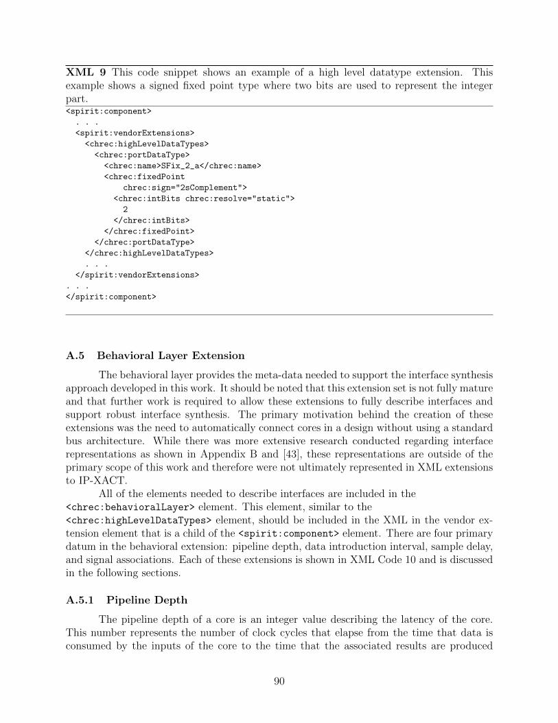
XML 9 This code snippet shows an example of a high level datatype extension. Thisexample shows a signed fixed point type where two bits are used to represent the integerpart.<spirit:component>
. . .
<spirit:vendorExtensions>
<chrec:highLevelDataTypes>
<chrec:portDataType>
<chrec:name>SFix_2_a</chrec:name>
<chrec:fixedPoint
chrec:sign="2sComplement">
<chrec:intBits chrec:resolve="static">
2
</chrec:intBits>
</chrec:fixedPoint>
</chrec:portDataType>
</chrec:highLevelDataTypes>
. . .
</spirit:vendorExtensions>
. . .
</spirit:component>
A.5 Behavioral Layer Extension
The behavioral layer provides the meta-data needed to support the interface synthesisapproach developed in this work. It should be noted that this extension set is not fully matureand that further work is required to allow these extensions to fully describe interfaces andsupport robust interface synthesis. The primary motivation behind the creation of theseextensions was the need to automatically connect cores in a design without using a standardbus architecture. While there was more extensive research conducted regarding interfacerepresentations as shown in Appendix B and [43], these representations are outside of theprimary scope of this work and therefore were not ultimately represented in XML extensionsto IP-XACT.
All of the elements needed to describe interfaces are included in the<chrec:behavioralLayer> element. This element, similar to the<chrec:highLevelDataTypes> element, should be included in the XML in the vendor ex-tension element that is a child of the <spirit:component> element. There are four primarydatum in the behavioral extension: pipeline depth, data introduction interval, sample delay,and signal associations. Each of these extensions is shown in XML Code 10 and is discussedin the following sections.
A.5.1 Pipeline Depth
The pipeline depth of a core is an integer value describing the latency of the core.This number represents the number of clock cycles that elapse from the time that data isconsumed by the inputs of the core to the time that the associated results are produced
90

XML 10 This code snippet is an example of the extension used to define the temporalinterface behavior of the core.<spirit:component>
. . .
<spirit:vendorExtensions>
. . .
<chrec:behavioralLayer>
<chrec:dataIntroductionInterval>
7
</chrec:dataIntroductionInterval>
<chrec:pipelineDepth>
8
</chrec:pipelineDepth>
<chrec:dataValid>
<chrec:signal>validIn</chrec:signal>
</chrec:dataValid>
<chrec:clockEnable>
<chrec:signal>ce</chrec:signal>
</chrec:clockEnable>
<chrec:sampleDelay>0</chrec:sampleDelay>
</chrec:behavioralLayer>
</spirit:vendorExtensions>
. . .
</spirit:component>
on the outputs. The fact that this element exists in XML does not mean that the core ispipelined in the traditional sense or that data can be accepted by the core on every cycle.Cores that accept data only every 8 cycles and take 9 to compute a result should also be givena pipeline depth value of 9. A core that is purely combinational should have a pipeline depthvalue of 0. One with a single register breaking the critical path should have a pipeline depthof 1 and so on. It is important when setting the pipeline depth to carefully consider whichregisters in a particular core actually contribute to the latency and which simply performstate functions.
A.5.2 Data Introduction Interval
The data introduction interval for a core is an integer value describing how many clockcycles must elapse between times that the core is able to accept input data. For examplea core that has a data introduction interval of 3 can consume data on clock cycle 0 butthen will not consume data again until clock cycle 3 and then again on cycle 6. This datais important when automatically interfacing cores because the interface system has to makesure that data is not introduced too quickly to the core.
A.5.3 Sample Delay
In any hardware systems involving feedback, this feedback allows samples later in adata stream to be compared to results of computations on earlier samples in the same stream.
91

A sample delay is listed on a core whose outputs will be used in calculations involving sampleslater in the data stream. For example, the outputs of a core with a sample delay of 1 wouldbe used in computations with the sample immediately following the one that produced thatparticular output. Similarly, a core with a sample delay of 2 would have its outputs used incomputations involving samples which were two later than the sample which produced thoseoutputs.
Figure 6.1 shows an example of sample delay in a QPSK radio design. In this designthere are essentially two loops, one through the NCO and another through the DDS. Thecolors on each of the cores show which sample in the stream the outputs of that core areassociated with. The outputs of the NCO and the DDS are one sample delayed from theirinputs as are the outputs on the calculateMu block. Each of these cores has a sample delayof 1 listed in their XML. It is notable that cores with sample delay can be chained andmultiple sample delays can exist in a feedback loop.
Any feedback loop in a circuit must be broken by at least one core with a sample delay.This is most obvious when considering a design that uses purely combinational cores. If thereis a feedback path and all cores are strictly combinational, an unstable system will result. Inorder to correct this problem, a register must be inserted in that loop to allow the feedbackto be properly used in a synchronous system. When creating high performance designs withpipelined cores, each of the registers inserted in the combinational design become a core witha sample delay.
The need for this behavior is also demonstrated by the system shown in figure 6.1.The large numbers next to blocks in the diagram represent clock cycles in which the registersin that particular block are clocked. These times are computed using a modification of theiterative modulo scheduling algorithm from [16]. This algorithm takes into account thesample delay and uses it to fold computations in the hardware loop into a short time. Notethat the core calculateMu block has a sample delay attribute of 1. This attribute allows it tobe scheduled in time slot 1 which is the same time slot that the y interpolator core begins.
A.5.4 Signal Associations
The final meta-data required to fully define the behavior of a core are several signalassociations. The interface synthesis system developed in this work requires that data validand clock enable signals exist on cores. The data valid signal indicates that the data on theinputs of the core is valid and that the core can consume them. The clock enable signalessentially is tied to the clock enable signal on all registers in the design. This allows coresin the design to be turned on and off at will by centralized control circuitry. These two dataallow the interface synthesis system to ensure that data flows correctly in the design. Theexample in XML Code 10 shows that for this particular core the clock enable signal is called“ce” and that the data valid signal is called “validIn.” The XML extension also allows formultiple clock enable signals and multiple data valid signals. If there are multiples of eithertype of signal, these signals must be associated in XML with the particular data or clocksignals that they control.
92

Appendix B
Dataflow Interface Automata
B.1 Introduction
Finite automata, both deterministic (DFA) and nondeterministic (NFA), have beenused to describe the protocol and timing behavior of cores with handshaking protocols whichinterface with various bus protocols. Several of these include those discussed in [33], [34], [35],[36], [37], [38], and [9]. A good discussion of automata theory for beginners is found in [44].This report introduces Dataflow Interface Automata (DIA). Dataflow Interface Automatadiffer from the automata described in the above cited works in that they are specificallyuseful in describing cores typically used for digital signal processing. Their strength is inmodeling feed forward cores with varying data introduction intervals and varying latenciesor pipeline depths.
B.2 Definition and Examples
A dataflow interface automaton can be modeled as two deterministic finite automata(DFA) which are connected by a transition function from a single state in one to a single statein the other. The first automata, called D, essentially models the input data introductionpattern while the second automata, called P , models the pipeline or latency from data inputto data output.
The overall automata is non-deterministic because the connection from d ∈ D top ∈ P should be the same as one of the transitions from the state d ∈ D to another statedn ∈ D. Despite the fact that this nondeterminism exists, dataflow interface automata donot experience the state explosion associated with traditional fully nondeterministic DFA’s.The definition of this automata as well as some mathematical examples are included below.
Definition 1: A dataflow interface automata (DIA) is the quadruple
A = 〈D,P,Σcontrol, δ〉
where
1. D = 〈Q,ΣinCtrld ,ΣinData, δd, η, q0〉 is a data introduction interval automata where
(a) Q is a finite set of states
(b) ΣinCtrld ∈ Σcontrol is a finite set of input control signals
(c) ΣinData is a finite set of input data signals
93

(d) δd : Q× Σcontrold → Q is the transition function
(e) η : Q× Σcontrold → ΣinData is a mapping of transitions to data inputs
(f) q0 ∈ Q is the start state
2. P = 〈Q,ΣinCtrlp ,ΣoutCtrlp ,ΣoutData, δp, ζ, F 〉 is a pipeline automata where
(a) Q is a finite set of states
(b) ΣinCtrlp ∈ Σcontrol is a finite set of input control signals
(c) ΣoutCtrlp ∈ Σcontrol is a finite set of output control signals
(d) ΣoutData is a finite set of output data signals
(e) δp : Q× Σcontrolp → Q is the transition function
(f) F ⊆ Q is the set of data output states and
(g) ζ : F → ΣoutData
3. Σcontrol is a finite set of control signals
4. δ : d ∈ D × Σcontrol → p ∈ P × ΣinData is the single transition from D to P
Example 1: Pure Functional Figure B.1 shows a diagram of a DIA (D1) that is notparameterized. This particular DIA represents a pipelined multiplier that accepts dataevery 2 clock cycles and has a pipeline depth of 3. In the diagram, input data signals thatare being sampled are followed by a ‘?’ (ex. xin?), and output signals that are asserted ina state are followed by a ‘!’ (ex. zout!). This syntax is similar to that used in [33]. Othersignals are control and are simply listed by name.
Figure B.1: A DIA (D1) showing a data introduction interval of 2 and a pipeline depth of 2.
The formal definition of D1 is 〈D,P,Σcontrol, δ〉 :
1. D = 〈Q,ΣinCtrld ,ΣinData, δd, η, q0〉 :
(a) Q = {d0, d1}
94

(b) ΣinCtrld = {clk}(c) ΣinData = {xin, yin}(d) δd is given as
clk
d0 {d1}
d1 {d0}
(e) η is given as
clk
d0 {xin, yin}
d1 ∅
(f) q0 = d0
2. P = 〈Q,ΣinCtrlp ,ΣoutCtrlp ,ΣoutData, δp, ζ, F 〉 :
(a) Q = {p0, p1, p2}(b) ΣinCtrlp = {clk}(c) ΣoutCtrlp = {∅}(d) ΣoutData = {zout}(e) δp is given as
clk
p0 p1
p1 p2
p2 ∅
(f) F = {p2}(g) ζ is given as p2 → {zout}
3. Σcontrol = {clk}
4. δ : d0 ∪ clk → p0 ∪ {xin, yin}
Example 2: Deterministic With Control Figure B.2 shows the diagram of DIA (D2)with an extra input control signal in addition to the clock signal. Similar to Figure B.1 itis an example for a pipelined multiplier that can accept input only every 2 clock cycles butalso requires that the dataV alid signal be asserted before data is read.
The formal definition of D2 is D2 = 〈D,P,Σcontrol, δ〉 :
1. D = 〈Q,ΣinCtrld ,ΣinData, δd, η, q0〉 :
95
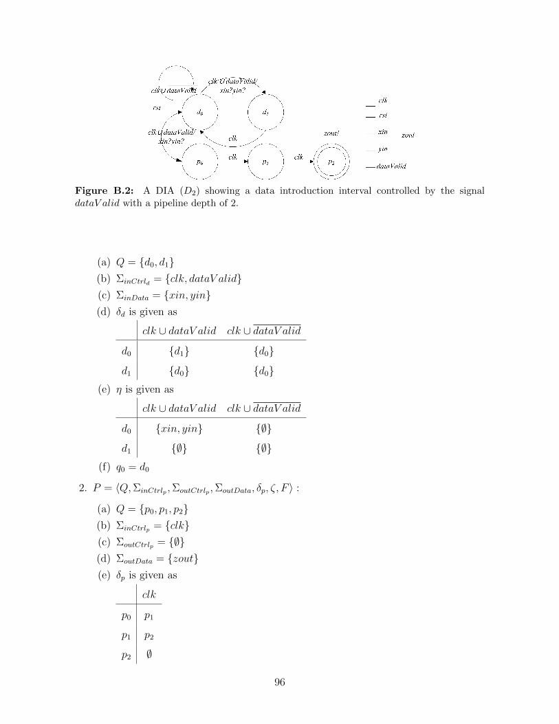
Figure B.2: A DIA (D2) showing a data introduction interval controlled by the signaldataV alid with a pipeline depth of 2.
(a) Q = {d0, d1}(b) ΣinCtrld = {clk, dataV alid}(c) ΣinData = {xin, yin}(d) δd is given as
clk ∪ dataV alid clk ∪ dataV alid
d0 {d1} {d0}
d1 {d0} {d0}(e) η is given as
clk ∪ dataV alid clk ∪ dataV alid
d0 {xin, yin} {∅}
d1 {∅} {∅}(f) q0 = d0
2. P = 〈Q,ΣinCtrlp ,ΣoutCtrlp ,ΣoutData, δp, ζ, F 〉 :
(a) Q = {p0, p1, p2}(b) ΣinCtrlp = {clk}(c) ΣoutCtrlp = {∅}(d) ΣoutData = {zout}(e) δp is given as
clk
p0 p1
p1 p2
p2 ∅
96

(f) F = {p2}(g) ζ is given as p2 → {zout}
3. Σcontrol = {clk}
4. δ : d0 ∪ clk → p0 ∪ {xin, yin}
Example 3: Non-deterministic Figure B.3 shows a DIA that models the behavior of acore that non deterministically processes input data and indicates that it is done processingand that data is ready with the dataRdy signal. The difficulty with this type of core is thatit cannot be statically scheduled.
Figure B.3: A DIA D3 showing the representation for a non-deterministic core that signalsits data is valid with a dataRdy signal.
The formal definition of D3 is D3 = 〈D,P,Σcontrol, δ〉 :
1. D = 〈Q,ΣinCtrld ,ΣinData, δd, η, q0〉 :
(a) Q = {d0, d1}(b) ΣinCtrld = {clk}(c) ΣinData = {xin, yin}(d) δd is given as
clk
d0 {d1}
d1 {d0}
(e) η is given as
97

clk
d0 {xin, yin}
d1 {∅}(f) q0 = d0
2. P = 〈Q,ΣinCtrlp ,ΣoutCtrlp ,ΣoutData, δp, ζ, F 〉 :
(a) Q = {p0, p1, p2}(b) ΣinCtrlp = {clk}(c) ΣoutCtrlp = {dataReady}(d) ΣoutData = {zout}(e) δp is given as
clk clk ∪ dataReady clk ∪ dataReady
p0 p1 − −
p1 − p1 p2
p2 {∅} − −(f) F = {p2}(g) ζ is given as p2 → {zout}
3. Σcontrol = {clk}
4. δ : d0 ∪ clk → p0 ∪ {xin, yin}
Example 4: Non-deterministic with required clear This is the DIA model for a corethat has a non-deteministic latency and requires that the user clear the core before introduc-ing new data to the core. This core also requires that this clear come at least one clock cycleafter the previous data is consumed. Essentially this core has a data introduction intervalof 2 with a required clear and a non-deterministic latency.
The formal definition of D4 is D4 = 〈D,P,Σcontrol, δ〉 :
1. D = 〈Q,ΣinCtrld ,ΣinData, δd, η, q0〉 :
(a) Q = {d0, d1, d3}(b) ΣinCtrld = {clk, clr}(c) ΣinData = {xin, yin}(d) δd is given as
clr clk ∪ clr clk ∪ clr
d0 − d1 d0
d1 d0 d3 −
d2 d0 d2 −
98

Figure B.4: A DIA D4 which models a core with a data introduction interval of 2 with arequired clear before data can be consumed. It also has a non-deterministic latency.
(e) η is given as
clk ∪ clr
d0 {xin, yin}
d1 {∅}
d2 {∅}
(f) q0 = d0
2. P = 〈Q,ΣinCtrlp ,ΣoutCtrlp ,ΣoutData, δp, ζ, F 〉 :
(a) Q = {p0, p1, p2}(b) ΣinCtrlp = {clk, clr}(c) ΣoutCtrlp = {dataRdy}(d) ΣoutData = {zout}(e) δp is given as
clk clr clk ∪ dataReady clk ∪ dataReady
p0 p1 {∅} − −
p1 − {∅} p1 p2
p2 {∅} {∅} {∅} {∅}
(f) F = {p2}(g) ζ is given as p2 → {zout}
3. Σcontrol = {clk}
4. δ : d0 ∪ clk → p0 ∪ {xin, yin}
99

Example 5: Multi-rate Systems (Upsample) This is the DIA model for a multi-ratesystem that does an upsample. Functionally, upsampling means that a core consumes dataat a slower rate than it produces corresponding output data. This is a common occurrencefor DSP cores.
Figure B.5: A DIA D5 which models a core which consumes data every other clock cycle butoutputs data every clock cycle. This is typical behavior for an upsampling core.
The formal definition for D5 is D5 = 〈D,P,Σcontrol, δ〉:
1. D = 〈Q,ΣinCtrld ,ΣinData, δd, η, q0〉 :
(a) Q = {d0, d1}(b) ΣinCtrld = {clk}(c) ΣinData = {data}(d) δd is given as
clk
d0 d1
d1 d0
(e) η is given as
clk
d0 {data}
d1 {∅}
(f) q0 = d0
100

2. P = 〈Q,ΣinCtrlp ,ΣoutCtrlp ,ΣoutData, δp, ζ, F 〉 :
(a) Q = {p0, p1}(b) ΣinCtrlp = {clk}(c) ΣoutCtrlp = {∅}(d) ΣoutData = {zout}(e) δp is given as
clk
p0 p1
p1 {∅}
(f) F = {p0, p1}(g) ζ is given as p0 → {zout} and p1 → {zout}
3. Σcontrol = {clk}
4. δ : d0 → p0 ∪ {data}
Example 6: Multi-rate Systems (Downsample) This is the DIA model for a multi ratesystem that does a downsample. Functionally, downsampling means that a core consumesdata at a faster rate than it produces corresponding output data. In this example(d6), thecore consumes data every clock cycle but only produces output data every other clock cycle.This is a common occurrence for DSP cores.
Figure B.6: A DIA D6 which models a core which consumes data every clock cycle andoutputs data every other clock. This is typical behavior for a downsampler.
The formal definition for D6 is D6 = 〈D,P,Σcontrol, δ〉:
101

1. D = 〈Q,ΣinCtrld ,ΣinData, δd, η, q0〉 :
(a) Q = {d0, d1}(b) ΣinCtrld = {clk}(c) ΣinData = {data}(d) δd is given as
clk
d0 d1
d1 d0
(e) η is given as
clk
d0 {data}
d1 {data}
(f) q0 = d0
2. P = 〈Q,ΣinCtrlp ,ΣoutCtrlp ,ΣoutData, δp, ζ, F 〉 :
(a) Q = {p0}(b) ΣinCtrlp = {∅}(c) ΣoutCtrlp = {∅}(d) ΣoutData = {zout}(e) δp is given as δp = {∅}(f) F = {p0}(g) ζ is given as p0 → {zout}
3. Σcontrol = {clk}
4. δ : d0 → p0 ∪ {data}
B.3 Visualizing DIA’s
It can be difficult to understand how these automata work by simply looking at math-ematics and diagrams. This section contains a series of figures which shows the operation ofthe DIA as different signals occur on the core. The DIA is functionally equivalent to D1.
102

d1d0
p1p0 p2
rst
clk/
xin?yin?
clk
clk/
xin?yin? clk clk
zout!
d1d0
p1p0 p2
rst
clk/
xin?yin?
clk
clk/
xin?yin? clk clk
zout!
d1d0
p1p0 p2
rst
clk/
xin?yin?
clk
clk/
xin?yin? clk clk
zout!
p2
d1d0
p1p0
rst
clk/
xin?yin?
clk
clk/
xin?yin? clk clk
zout!
Signals
rst
clk
clk
clk
Signals
rst
clk
clk
clk
Signals
rst
clk
clk
clk
Signals
rst
clk
clk
clk
Figure B.7: This series of DIA’s shows the progression through the machine D1 as signalsoccur on the core. The red states are active and the red arrows are the transitions that wereused to activate that state. The progression of signals is shown on the right of each segmentwith the arrow pointing to the signal last used.
103

104

Appendix C
The IP-XACT Extensions Schema
This appendix contains the verbatim code from the schema that defines extensions toIP-XACT for higher levels of abstraction. The code is well documented and is included asan example of how these extensions can be implemented. The implementation of the schemaconsists of several schema (.xsd) files and each is listed here.
C.1 CHREC Extensions
The chrecExtensions.xsd file is the file that should be referenced in XML thatrequires extensions defined in this schema. It defines the set of extension elements andallows user access to them.
CHRECExt/chrecExtension.xsd
1 <?xml version=” 1 .0 ” encoding=”UTF−8” ?>< !−−// Des c r i p t i on : chrecExtens ions . xsd// Author: Brigham Young Univers i t y , CHREC B1 , Adam Arnesen// Vers ion: 2 .0
6 // Date: 2010/12/20//// Copyright ( c ) 2010 , Brigham Young Un i v e r s i t y Con f i gurab l e Computing Lab
, A l l r i g h t s r e s e rved .// h t t p : // c c l . ee . byu . edu//
11 // This source f i l e i s prov ided on an AS IS ba s i s . Brigham YoungUn i ve r s i t y d i s c l a ims
// ANYWARRANTY EXPRESS OR IMPLIED INCLUDING ANYWARRANTY OF// MERCHANTABILITY AND FITNESS FOR USE FOR A PARTICULAR PURPOSE.// The user o f the source f i l e s h a l l indemnify and ho ld Brigham Young
Un i ve r s i t y harmless// from any damages or l i a b i l i t y a r i s i n g out o f the use t h e r e o f or the
performance or16 // implementat ion or p a r t i a l implementat ion o f the schema .−−>
<xs:schema targetNamespace=” h t t p : // c c l . ee . byu . edu”elementFormDefault=” q u a l i f i e d ” attr ibuteFormDefaul t=” q u a l i f i e d ”xmlns :xs=” h t t p : //www. w3 . org /2001/XMLSchema” xmlns :chrec=” h t t p : // c c l . ee .
byu . edu”>21 <x s : i n c l u d e schemaLocation=” h s d f I n t e r f a c e . xsd” />
<x s : i n c l u d e schemaLocation=” highLevelDataTypes . xsd” /><x s : i n c l u d e schemaLocation=” parameter . xsd” /><x s : i n c l u d e schemaLocation=” por t s . xsd” />
105

26 <xs : e l ement name=” highLevelDataTypes ” type=” chrec:portsDataTypeType ”><xs : annota t i on>
<xs :documentat ion>This d e f i n e s the high l e v e l data types . One o fthe se should be a s s o c i a t e d with each port on an IP core .
31 </ xs :documentat ion></ xs : annota t i on>
</ xs : e l ement>
<xs : e l ement name=” behav iora lLayer ” type=”chrec :hsd fBehav iora lExtens ionType ”>
36 <xs : annota t i on><xs :documentat ion>
This d e f i n e s the i n t e r f a c e parameters f o r H−SDFCores .
</ xs :documentat ion>41 </ xs : annota t i on>
</ xs : e l ement>
<xs : e l ement name=” portExtens ion ” type=” chrec :portExtens ionType ”>46 <xs : annota t i on>
<xs :documentat ion>This ex t ens i on prov ide s a high l e v e l typer e f e r e n c e , a r e s e t value , and a c a t e g o r i z a t i o n o f a port .
</ xs :documentat ion>51 </ xs : annota t i on>
</ xs : e l ement>
<xs : e l ement name=” parameterExtension ” type=” chrec :parameterExtens ionType”>
56 <xs : annota t i on><xs :documentat ion>
The parameter ex tens i on adds three e lements toparameter va lue s . I t i n d i c a t e s i f a parameter i s an ac tua l
parameter( i . e . g e n e r i c ) inc luded in HDL sources , and a l l ows f o r parameters
to61 have dependent minimum and maximum va lues .
</ xs :documentat ion></ xs : annota t i on>
</ xs : e l ement></ xs:schema>
C.2 Parameters
This file provides extensions for resolving minimum and maximum values on param-eters. IP-XACT 1.4 allows parameters only to have static minimum and maximum values.This extensions allows min and max values to depend on other elements’ values or on math-ematical expressions as defined by an XPath Expression. It also allows parameters to be
106

tagged as HDL parameters. This means that the parameter is an actual parameter thatmust be set in generated HDL. In VHDL this means that the parameter is a generic in theVHDL and must be properly overwritten in generated code.
CHRECExt/parameter.xsd
<?xml version=” 1 .0 ” encoding=”UTF−8”?>< !−−// Des c r i p t i on : parameter . xsd// Author: Brigham Young Univers i t y , CHREC B1 , Adam Arnesen
5 // Vers ion: 2 .0// Date: 2010/12/20//// Copyright ( c ) 2010 , Brigham Young Un i v e r s i t y Con f i gurab l e Computing Lab
, A l l r i g h t s r e s e rved .// h t t p : // c c l . ee . byu . edu
10 //// This source f i l e i s prov ided on an AS IS ba s i s . Brigham Young
Un i ve r s i t y d i s c l a ims// ANYWARRANTY EXPRESS OR IMPLIED INCLUDING ANYWARRANTY OF// MERCHANTABILITY AND FITNESS FOR USE FOR A PARTICULAR PURPOSE.// The user o f the source f i l e s h a l l indemnify and ho ld Brigham Young
Un i ve r s i t y harmless15 // from any damages or l i a b i l i t y a r i s i n g out o f the use t h e r e o f or the
performance or// implementat ion or p a r t i a l implementat ion o f the schema .−−>
<xs:schema targetNamespace=” h t t p : // c c l . ee . byu . edu”elementFormDefault=” q u a l i f i e d ” attr ibuteFormDefaul t=” q u a l i f i e d ”
20 xmlns :xs=” h t t p : //www. w3 . org /2001/XMLSchema” xmlns :chrec=” h t tp : // c c l . ee .byu . edu”>
<xs:complexType name=” parameterExtensionType ”><xs : annota t i on>
<xs :documentat ion>25 This type prov ide s CHREC XML ext en s i on s to IP−XACT
f o r r e s o l v i n g minimum and maximum va lues on parameters . IP−XACT1.4
only a l l ows parameters to have s t a t i c minimum and maximum va lues .This ex t en s i on s a l l ows min and max va lues to depend on othere lements va lue s or on mathematical e x p r e s s i o n s as de f ined by an
30 XPath Express ion . I t a l s o a l l ows parameters to be tagged as HDLparameters . This means that the parameter i s an ac tua l parameterthat must be s e t in generated HDL. In VHDL t h i s means that theparameter i s a g e n e r i c in the VHDL and must be proper ly
ove rwr i t t en .</ xs :documentat ion>
35 </ xs : annota t i on><xs : s equence>
<xs : e l ement name=”isHDLParameter” maxOccurs=”1” minOccurs=”0”><xs : annota t i on>
<xs :documentat ion>40 This i s a tag that has no content . I f the tag i s
107

present in the XML f o r a p a r t i c u l a r parameter i t i si n t e r p r e t e d
that that parameter i s an HDL parameter and should beove rwr i t t en
in generated code .</ xs :documentat ion>
45 </ xs : annota t i on></ xs : e l ement><xs : e l ement name=”dependentMinimum” type=” x s : s t r i n g ”
maxOccurs=”1” minOccurs=”0”><xs : annota t i on>
50 <xs :documentat ion>This i s an XPath expr e s s i on supply ing ther e s u l t a n t va lue f o r the conta in ing element in terms o f otherp r o p e r t i e s in the conta in ing f i l e .
</ xs :documentat ion>55 </ xs : annota t i on>
</ xs : e l ement><xs : e l ement name=”dependentMaximum” type=” x s : s t r i n g ”
maxOccurs=”1” minOccurs=”0”><xs : annota t i on>
60 <xs :documentat ion>This i s an XPath expr e s s i on supply ing ther e s u l t a n t va lue f o r the conta in ing element in terms o f otherp r o p e r t i e s in the conta in ing f i l e .
</ xs :documentat ion>65 </ xs : annota t i on>
</ xs : e l ement></ xs : s equence>
</ xs:complexType></ xs:schema>
C.3 High-Level Datatypes
This file the high-level datatypes. It shows types for bit vector, strings, integers,floating point, fixed point, character, Boolean and user custom types.
CHRECExt/highLevelDataTypes.xsd
1 <?xml version=” 1 .0 ” encoding=”UTF−8”?>< !−−// Des c r i p t i on : highLevelDataTypes . xsd// Author: Brigham Young Univers i t y , CHREC B1 , Adam Arnesen// Vers ion: 2 .0
6 // Date: 2010/12/20//// Copyright ( c ) 2010 , Brigham Young Un i v e r s i t y Con f i gurab l e Computing Lab
, A l l r i g h t s r e s e rved .// h t t p : // c c l . ee . byu . edu//
11 // This source f i l e i s prov ided on an AS IS ba s i s . Brigham YoungUn i ve r s i t y d i s c l a ims
// ANYWARRANTY EXPRESS OR IMPLIED INCLUDING ANYWARRANTY OF// MERCHANTABILITY AND FITNESS FOR USE FOR A PARTICULAR PURPOSE.
108

// The user o f the source f i l e s h a l l indemnify and ho ld Brigham YoungUn i ve r s i t y harmless
// from any damages or l i a b i l i t y a r i s i n g out o f the use t h e r e o f or theperformance or
16 // implementat ion or p a r t i a l implementat ion o f the schema .−−>
<xs:schema targetNamespace=” h t t p : // c c l . ee . byu . edu”elementFormDefault=” q u a l i f i e d ” attr ibuteFormDefaul t=” q u a l i f i e d ”xmlns :xs=” h t t p : //www. w3 . org /2001/XMLSchema” xmlns :chrec=” h t t p : // c c l . ee .
byu . edu”>21 <x s : i n c l u d e schemaLocation=” c o n f i g u r a b l e . xsd”></ x s : i n c l u d e>
<x s : i n c l u d e schemaLocation=”commonElements . xsd”></ x s : i n c l u d e>< !−− ============================= −−>< !−− complexType: portsDataTypeType −−>< !−− ============================= −−>
26 <xs:complexType name=”portsDataTypeType”><xs : annota t i on>
<xs :documentat ion>This type conta in s a s e t o f high−l e v e l port datatypes .</ xs :documentat ion>
</ xs : annota t i on>31 <xs : s equence>
<xs : e l ement name=”portDataType” type=” chrec:portDataTypeType ”maxOccurs=”unbounded” />
</ xs : s equence></ xs:complexType>
36< !−− ============================= −−>< !−− complexType: portDataTypeType −−>< !−− ============================= −−><xs:complexType name=”portDataTypeType”>
41 <xs : annota t i on><xs :documentat ion>
This type d e s c r i b e s a core data type . For a datatype there are 2 mandatory e l ement s :1) name −> a name f o r the data type used to r e f e r e n c e the type
with in the XML ( Ex: s ing l eB i tWire ) .46 Data types can be de s c r ibed with more d e t a i l .
The f o l l o w i n g can a l s o d e s c r i b e the data type :1) types −> the port can be a s s o c i a t e d with one o f the f o l l o w i n g
pre−de f ined data t y p e s :a ) s t r i n gb) i n t −> has a ’ s i gn ’ a s s o c i a t e d
51 c ) f l o a t i n g po int −> assumes 1 b i t f o r s ign , c o n f i g u r a b l e numbero f f r a c t i o n / exponent b i t s
d) f i x e d po int −> has a ’ s i gn ’ and c o n f i g u r a b l e number o ff r a c t i o n b i t s
e ) charac t e r (8 b i t ASCI)f ) booleang ) a custom type −> any number o f custom bit−maping f i e l d s can
be c rea ted .56 </ xs :documentat ion>
</ xs : annota t i on><xs : s equence>
<xs :group r e f=”chrec:nameOnlyGroup” />
109

<x s : c h o i c e minOccurs=”1”>61 <xs : e l ement name=” bi tVector ” n i l l a b l e=” true ” />
<xs : e l ement name=” s t r i n g ” type=” chre c : s t r i ngType ” /><xs : e l ement name=” i n t ” type=” chrec : in tType ” /><xs : e l ement name=” f l o a t i n g P o i n t ” type=” chr e c : f l o a t i ngPo in tType ” /><xs : e l ement name=” f i x edPo in t ” type=” chrec : f i xedPo intType ” />
66 <xs : e l ement name=” charac t e r ” type=” chrec : characte rType ” /><xs : e l ement name=” boolean ” type=” chrec :booleanType ” /><xs : e l ement name=”custom” type=” chrec:customType ” />
</ x s : c h o i c e></ xs : s equence>
71 </ xs:complexType>
< !−− ============================= −−>< !−− complexType: corePortDataTypes −−>< !−− ============================= −−>
76 <xs:complexType name=” str ingType ”><xs : annota t i on>
<xs :documentat ion>I f t h i s element i s pre sent the port i s o f types t r i n g as per VHDL s t r i n g typing .
81 </ xs :documentat ion></ xs : annota t i on>
</ xs:complexType>
< !−− ============================= −−>86 < !−− complexType: corePortDataTypes −−>
< !−− ============================= −−><xs:complexType name=” intType ”>
<xs : annota t i on><xs :documentat ion>
91 This type d e s c r i b e s the i n t data type . A ’ s i gn ’a t t r i b u t e i s r equ i r ed . I f the s i gn i s dependent on a parameter ( asi s the case with many COREGen co r e s ) , @dependent and @dependencya t t r i b u t e s should be used .
</ xs :documentat ion>96 </ xs : annota t i on>
<xs :a t t r ibuteGroup r e f=” c h r e c : c o n f i g u r a b l e ” /><x s : a t t r i b u t e name=” s i gn ” type=” chrec : in tS ignType ” use=” requ i r ed ” />
</ xs:complexType>
101 < !−− ============================= −−>< !−− complexType: corePortDataTypes −−>< !−− ============================= −−><xs:complexType name=” f loat ingPo intType ”>
<xs : annota t i on>106 <xs :documentat ion>
The f l o a t i n g po int type i s s i m i l a r to the IEEE standard f o rf l o a t i n g po int
r e p r e s e n t a t i o n s . I t has three f i e l d s , [ 1 s i gn b i t ] [ k b i t s f o rexponent ] [ n b i t s f o r f r a c t i o n o f s i g n i f i c a n d ] . The only s p e c i f i e r
weneed i s the k b i t s f o r the exponent ( s i n c e we assume only 1 s i gn
bit ,
110

111 and the t o t a l b i twidth i s s p e c i f i e d by the ’ b i tVector ’ )</ xs :documentat ion>
</ xs : annota t i on><xs : s equence>
<x s : c h o i c e>116 <xs : e l ement name=”numExponentBits” type=” chre c : con f i gu rab l eType ”
default=”8” /><xs : e l ement name=” numFractionBits ” type=” chrec : con f i gu rab l eType ”
default=”23” /></ x s : c h o i c e>
121 <xs : e l ement name=” guardBit ” minOccurs=”0” /><xs : e l ement name=” roundBit ” minOccurs=”0” /><xs : e l ement name=” s t i c k y B i t ” minOccurs=”0” /><xs : e l ement name=”roundingScheme” type=” chrec :roundingType ”
minOccurs=”0” />126 </ xs : s equence>
</ xs:complexType>
< !−− ============================= −−>< !−− complexType: corePortDataTypes −−>
131 < !−− ============================= −−><xs:complexType name=” f ixedPointType ”>
<xs : annota t i on><xs :documentat ion>
The f i x e d po int has three important a t t r i b u t e s : b i t s be f o r edecimal
136 ( i n t B i t s ) , b i t s a f t e r decimal ( f r a c B i t s ) , and t o t a l b i t s ( Ex:11010.11110100010) S ince the t o t a l number i f b i t s i s known (
s p e c i f i e dby the ’ b i tVector ’ ) , only ’ i n t B i t s ’ or ’ f r a c B i t s ’ i s r equ i r ed . Thevalue o f both ’ i n t B i t s ’ and ’ f r a c B i t s ’ can be determined by a
parameter( ’ i n tB i t s Re f ’ and ’ f r a c B i t s R e f ’ ) or by a math expr e s s i on
141 ( ’ i n tB i t sEx pr e s s i on ’ and ’ f r a c B i t s E x p r e s s i o n ’ ) . A ’ s i gn ’ a t t r i b u t ei s
r equ i r ed . I f the s i gn i s dependent on a parameter ( as i s the casewith
many COREGen co r e s ) , the ’ s i gn ’ i s s e t to ’ dependent ’ and the’ dependentSigns ’ element i s used .
</ xs :documentat ion>146 </ xs : annota t i on>
<xs : s equence><x s : c h o i c e>
<xs : e l ement name=” i n t B i t s ” type=” chrec : con f i gu rab l eType ” /><xs : e l ement name=” f r a c B i t s ” type=” chrec : con f i gu rab l eType ” />
151 </ x s : c h o i c e><xs : e l ement name=” s ignRef ” type=” chrec : con f i gu rab l eType ”
minOccurs=”0” maxOccurs=”1”/><xs : e l ement name=”roundingScheme” type=” chrec :roundingType ”
minOccurs=”0” maxOccurs=”1”/>156 </ xs : s equence>
<x s : a t t r i b u t e name=” s i gn ” type=” chrec : in tS ignType ” use=” requ i r ed ” /></ xs:complexType>
111

< !−− ============================= −−>161 < !−− complexType: corePortDataTypes −−>
< !−− ============================= −−><xs:complexType name=” characterType ”>
<xs : annota t i on><xs :documentat ion>
166 I f t h i s element i s pre sent the port i s o f typecharac t e r as per VHDL charac t e r typing .
</ xs :documentat ion></ xs : annota t i on>
</ xs:complexType>171
< !−− ============================= −−>< !−− complexType: corePortDataTypes −−>< !−− ============================= −−><xs:complexType name=”booleanType”>
176 <xs : annota t i on><xs :documentat ion>
I f t h i s element i s pre sent the port i s o f typeboolean as per VHDL s t r i n g typing .
</ xs :documentat ion>181 </ xs : annota t i on>
</ xs:complexType>
< !−− ============================= −−>< !−− complexType: corePortDataTypes −−>
186 < !−− ============================= −−><xs:complexType name=”customType”>
<xs : annota t i on><xs :documentat ion>
This type i s to be used f o r types that are not191 commonly found or are types that are s p e c i f i c to a
c e r t a i n HDL f i l e .This type i s b u i l t o f a s e t o f ’ f i e l d s ’ . A f i e l d i s s imply a s e t
o fb i t s with a name .A f i e l d a l s o has a s p e c i f i e d b i t range which
196 i n d i c a t e s the l o c a t i o n o f the f i e l d with in the o v e r a l lword .
</ xs :documentat ion></ xs : annota t i on><xs : s equence>
201 <xs : e l ement name=” f i e l d s ” type=” c h r e c : f i e l d s T y p e ” /></ xs : s equence>
</ xs:complexType>
< !−− ============================= −−>206 < !−− s impleType: intSignType −−>
< !−− ============================= −−><xs :s impleType name=” intSignType ”>
<xs : annota t i on><xs :documentat ion>This type l i s t s a l l b inary i n t e g e r unsigned / s igned
211 types .</ xs :documentat ion></ xs : annota t i on>
112

<x s : r e s t r i c t i o n base=” xs : token ”><xs :enumerat ion value=” unsigned ” /><xs :enumerat ion value=”1sComplement” />
216 <xs :enumerat ion value=”2sComplement” /><xs :enumerat ion value=” signMagnitude ” /><xs :enumerat ion value=” dependent ” />
</ x s : r e s t r i c t i o n></ xs :s impleType>
221< !−− ============================= −−>< !−− s impleType: roundingType −−>< !−− ============================= −−><xs :s impleType name=”roundingType”>
226 <xs : annota t i on><xs :documentat ion>This type l i s t s a l l p o s s i b l e rounding types .</ xs :documentat ion>
</ xs : annota t i on><x s : r e s t r i c t i o n base=” xs : token ”>
231 <xs :enumerat ion value=”RoundToNearestEven” /><xs :enumerat ion value=”RoundToward0” /><xs :enumerat ion value=”RoundToward+I n f i n i t y ” /><xs :enumerat ion value=”RoundToward−I n f i n i t y ” />
</ x s : r e s t r i c t i o n>236 </ xs :s impleType>
< !−− ============================= −−>< !−− complexType: f i e l d sType −−>< !−− ============================= −−>
241 <xs:complexType name=” f i e l d sType ”><xs : annota t i on>
<xs :documentat ion>This type i n c l u d e s a s e t o f custom data typef i e l d s .</ xs :documentat ion>
</ xs : annota t i on>246 <xs : s equence>
<xs : e l ement name=” f i e l d ” type=” c h r e c : f i e l d T y p e ” maxOccurs=”unbounded” />
</ xs : s equence></ xs:complexType>
251 < !−− ============================= −−>< !−− complexType: corePortDataTypes −−>< !−− ============================= −−><xs:complexType name=” f i e ldType ”>
<xs : annota t i on>256 <xs :documentat ion>
This type d e s c r i b e s a custom data type f i e l d . Thef i e l d has a name and one or more i d e n t i f i e d abso lu t e b i t ranges .
Inother words a s i n g l e f i e l d can be i n t e r s p e r s e d among other f i e l d s( Ex: a s i n g l e f i e l d can be a l l even b i t s − which would r e q u i r e a
261 number o f ’ f i e ldRange ’ e lements ) . Note that a ’ f i e ldRange ’r e q u i r e s
a ’ l e f t ’ and a ’ r i g h t ’ and i s not merely a b i twidth . The ’ l e f t ’and
113

’ r i g h t ’ va lue s are abso lu t e in terms o f the f u l l port b i twidth .</ xs :documentat ion>
</ xs : annota t i on>266 <xs : s equence>
<xs :group r e f=” chrec:nameGroupOptional ” /><xs : e l ement name=” f i e ldRange ” type=” chrec :vectorType ”
maxOccurs=”1” minOccurs=”1”/></ xs : s equence>
271 </ xs:complexType></ xs:schema>
C.4 H-SDF Interface Definitions
This file defines the description of the H-SDF model of the core. It includes thelatency, data introduction interval and sample delay on a core.
CHRECExt/hsdfInterface.xsd
<?xml version=” 1 .0 ” encoding=”UTF−8”?>< !−−
3 // Des c r i p t i on : h s d f I n t e r f a c e . xsd// Author: Brigham Young Univers i t y , CHREC B1 , Adam Arnesen// Vers ion: 2 .0// Date: 2010/12/20//
8 // Copyright ( c ) 2010 , Brigham Young Un i v e r s i t y Con f i gurab l e Computing Lab, A l l r i g h t s r e s e rved .
// h t t p : // c c l . ee . byu . edu//// This source f i l e i s prov ided on an AS IS ba s i s . Brigham Young
Un i ve r s i t y d i s c l a ims// ANYWARRANTY EXPRESS OR IMPLIED INCLUDING ANYWARRANTY OF
13 // MERCHANTABILITY AND FITNESS FOR USE FOR A PARTICULAR PURPOSE.// The user o f the source f i l e s h a l l indemnify and ho ld Brigham Young
Un i ve r s i t y harmless// from any damages or l i a b i l i t y a r i s i n g out o f the use t h e r e o f or the
performance or// implementat ion or p a r t i a l implementat ion o f the schema .−−>
18 <xs:schema targetNamespace=” h t t p : // c c l . ee . byu . edu”elementFormDefault=” q u a l i f i e d ” attr ibuteFormDefaul t=” q u a l i f i e d ”xmlns :xs=” h t t p : //www. w3 . org /2001/XMLSchema” xmlns :chrec=” h t t p : // c c l . ee .
byu . edu”>
<xs:complexType name=” hsdfBehaviora lExtens ionType ”>23 <xs : annota t i on>
<xs :documentat ion>This type should be used f o r H−SDF with a f i x e dla t ency and data i n t r o d u c t i o n i n t e r v a l .
</ xs :documentat ion>28 </ xs : annota t i on>
<xs : s equence><xs : e l ement name=” d a t a I n t r o d u c t i o n I n t e r v a l ” type=” x s : i n t ”
maxOccurs=”1” minOccurs=”1”>
114

<xs : annota t i on>33 <xs :documentat ion>
This i s the number o f c y c l e s that e l a p s e betweent imes that data i s expected on the inputs to the core .
</ xs :documentat ion></ xs : annota t i on>
38 </ xs : e l ement><xs : e l ement name=” la t ency ” type=” x s : i n t ” maxOccurs=”1”
minOccurs=”1”><xs : annota t i on>
<xs :documentat ion>43 This i s the number o f c l o ck c y c l e s that e l a p s e
from the time that data i s consumed on inputs u n t i lcor re spond ing
data i s produced on output por t s .</ xs :documentat ion>
</ xs : annota t i on>48 </ xs : e l ement>
<xs : e l ement name=” sampleDelay ” type=” x s : i n t ” maxOccurs=”1”minOccurs=”0”><xs : annota t i on>
< !−− TODO: This shou ld be removed when we t r a n s i t i o n to samplede lay
53 b l o c k s . −−><xs :documentat ion>
DEPRECATED: This w i l l be r ep laced with the samplede lay b locks . In cur rent work t h i s i s the element that says i f
theoutputs should be delayed a sample c y c l e from i t s inputs .
58 </ xs :documentat ion></ xs : annota t i on>
</ xs : e l ement><xs : e l ement name=” dataVal id ” type=” c h r e c : s i g n a l A s s o c i a t i o n T y p e ”
maxOccurs=”unbounded” minOccurs=”0”>63 <xs : annota t i on>
<xs :documentat ion>This a s s o c i a t e s the data v a l i d s i g n a l f o r thecore . This i s not a r equ i r ed element , however , i f i t i s notpre sent and a data v a l i d s i g n a l does e x i s t on the core ,
68 f u n c t i o n a l i t y i s not guaranteed .</ xs :documentat ion>
</ xs : annota t i on></ xs : e l ement><xs : e l ement name=” clockEnable ” type=” c h r e c : s i g n a l A s s o c i a t i o n T y p e ”
73 maxOccurs=”1” minOccurs=”0”><xs : annota t i on>
<xs :documentat ion>This a s s o c i a t e s the c l o ck enable s i g n a l f o r thecore . This i s not a r equ i r ed element , however , i f i t i s not
78 pre sent and a c l o ck enable s i g n a l does e x i s t on the core ,f u n c t i o n a l i t y i s not guaranteed f o r the core or f o r the des ign
.</ xs :documentat ion>
</ xs : annota t i on>
115

</ xs : e l ement>83 </ xs : s equence>
</ xs:complexType>
<xs:complexType name=” s igna lAssoc ia t i onType ”><xs : annota t i on>
88 <xs :documentat ion>Used to a s s o c i a t e s i g n a l s .</ xs :documentat ion></ xs : annota t i on><xs : s equence>
<xs : e l ement name=” s i g n a l ” type=” x s : s t r i n g ” maxOccurs=”1”minOccurs=”1” />
93 <xs : e l ement name=” s i g n a l A s s o c i a t i o n ” type=” x s : s t r i n g ”maxOccurs=”unbounded” minOccurs=”0” />
</ xs : s equence></ xs:complexType>
</ xs:schema>
C.5 Port Extensions
The extensions described in this file are included on a port in IP-XACT to categorizeit as a clock, reset, control, data, address, or unknown category. These categories are usedto interface with the LabVIEW FPGA CLIP node [15].
CHRECExt/ports.xsd
<?xml version=” 1 .0 ” encoding=”UTF−8”?>2 < !−−
// Des c r i p t i on : po r t s . xsd// Author: Brigham Young Univers i t y , CHREC B1 , Adam Arnesen// Vers ion: 2 .0// Date: 2010/12/20
7 //// Copyright ( c ) 2010 , Brigham Young Un i v e r s i t y Con f i gurab l e Computing Lab
, A l l r i g h t s r e s e rved .// h t t p : // c c l . ee . byu . edu//// This source f i l e i s prov ided on an AS IS ba s i s . Brigham Young
Un i ve r s i t y d i s c l a ims12 // ANYWARRANTY EXPRESS OR IMPLIED INCLUDING ANYWARRANTY OF
// MERCHANTABILITY AND FITNESS FOR USE FOR A PARTICULAR PURPOSE.// The user o f the source f i l e s h a l l indemnify and ho ld Brigham Young
Un i ve r s i t y harmless// from any damages or l i a b i l i t y a r i s i n g out o f the use t h e r e o f or the
performance or// implementat ion or p a r t i a l implementat ion o f the schema .
17 −−><xs:schema targetNamespace=” h t t p : // c c l . ee . byu . edu”
elementFormDefault=” q u a l i f i e d ” attr ibuteFormDefaul t=” q u a l i f i e d ”xmlns :xs=” h t t p : //www. w3 . org /2001/XMLSchema” xmlns :chrec=” h t t p : // c c l . ee .
byu . edu”><x s : i n c l u d e schemaLocation=”commonElements . xsd” />
22<xs:complexType name=” portExtensionType ”>
116
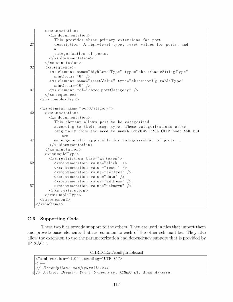
<xs : annota t i on><xs :documentat ion>
This prov ide s three primary ex t en s i on s f o r port27 d e s c r i p t i o n . A high−l e v e l type , r e s e t va lue s f o r ports , and
ac a t e g o r i z a t i o n o f por t s .
</ xs :documentat ion></ xs : annota t i on>
32 <xs : s equence><xs : e l ement name=” highLevelType ” type=” chrec :ba s i cS t r ingType ”
minOccurs=”0” /><xs : e l ement name=” rese tVa lue ” type=” chrec : con f i gu rab l eType ”
minOccurs=”0” />37 <xs : e l ement r e f=” chrec :por tCategory ” />
</ xs : s equence></ xs:complexType>
<xs : e l ement name=” portCategory ”>42 <xs : annota t i on>
<xs :documentat ion>This element a l l ows port to be c a t e g o r i z e daccord ing to t h e i r usage type . These c a t e g o r i z a t i o n s aroseo r i g i n a l l y from the need to match LabVIEW FPGA CLIP node XML but
are47 more g e n e r a l l y a p p l i c a b l e f o r c a t e g o r i z a t i o n o f pro t s . .
</ xs :documentat ion></ xs : annota t i on><xs :s impleType>
<x s : r e s t r i c t i o n base=” xs : token ”>52 <xs :enumerat ion value=” c l o ck ” />
<xs :enumerat ion value=” r e s e t ” /><xs :enumerat ion value=” c o n t r o l ” /><xs :enumerat ion value=” data ” /><xs :enumerat ion value=” address ” />
57 <xs :enumerat ion value=”unknown” /></ x s : r e s t r i c t i o n>
</ xs :s impleType></ xs : e l ement>
</ xs:schema>
C.6 Supporting Code
These two files provide support to the others. They are used in files that import themand provide basic elements that are common to each of the other schema files. They alsoallow the extension to use the parameterization and dependency support that is provided byIP-XACT.
CHRECExt/configurable.xsd
<?xml version=” 1 .0 ” encoding=”UTF−8”?>< !−−// Des c r i p t i on : c on f i g u r a b l e . xsd
4 // Author: Brigham Young Univers i t y , CHREC B1 , Adam Arnesen
117

// Vers ion: 2 .0// Date: 2010/12/20//// Copyright ( c ) 2010 , Brigham Young Un i v e r s i t y Con f i gurab l e Computing Lab
, A l l r i g h t s r e s e rved .9 // h t t p : // c c l . ee . byu . edu
//// This source f i l e i s prov ided on an AS IS ba s i s . Brigham Young
Un i ve r s i t y d i s c l a ims// ANYWARRANTY EXPRESS OR IMPLIED INCLUDING ANYWARRANTY OF// MERCHANTABILITY AND FITNESS FOR USE FOR A PARTICULAR PURPOSE.
14 // The user o f the source f i l e s h a l l indemnify and ho ld Brigham YoungUn i ve r s i t y harmless
// from any damages or l i a b i l i t y a r i s i n g out o f the use t h e r e o f or theperformance or
// implementat ion or p a r t i a l implementat ion o f the schema .−−>
<xs:schema targetNamespace=” h t t p : // c c l . ee . byu . edu”19 elementFormDefault=” q u a l i f i e d ” attr ibuteFormDefau l t=” q u a l i f i e d ”
xmlns :xs=” h t t p : //www. w3 . org /2001/XMLSchema” xmlns :chrec=” h t t p : // c c l . ee .byu . edu”>
<x s : i n c l u d e schemaLocation=”commonElements . xsd” />
<x s : a t t r i b u t e name=” r e s o l v e ” type=” chrec : r e so l v eType ”24 default=” s t a t i c ”>
<xs : annota t i on><xs :documentat ion>Determines how a property value i s r e s o l v e d .</ xs :documentat ion>
</ xs : annota t i on>29 </ x s : a t t r i b u t e>
<x s : a t t r i b u t e name=” id ” type=” xs : ID ”><xs : annota t i on>
<xs :documentat ion>34 ID a t t r i b u t e f o r unique ly i d e n t i f y i n g an element
with in i t s document .</ xs :documentat ion>
</ xs : annota t i on></ x s : a t t r i b u t e>
39<x s : a t t r i b u t e name=”dependency” type=” x s : s t r i n g ”>
<xs : annota t i on><xs :documentat ion>Required on p r o p e r t i e s with a r e s o l v e = ” dependent
”a t t r i b u t e . This i s an XPath expr e s s i on supply ing the r e s u l t a n t
value44 f o r the conta in ing element in terms o f other p r o p e r t i e s in the
conta in ing f i l e . </ xs :documentat ion></ xs : annota t i on>
</ x s : a t t r i b u t e>
49 <xs :a t t r ibuteGroup name=” c o n f i g u r a b l e ”><xs : annota t i on>
<xs :documentat ion>
118

Base s e t o f a t t r i b u t e s f o r an element to bec o n f i g u r a b l e . This i s from IP−XACT
54 </ xs :documentat ion></ xs : annota t i on><x s : a t t r i b u t e r e f=” c h r e c : r e s o l v e ” /><x s : a t t r i b u t e r e f=” c h r e c : i d ” /><x s : a t t r i b u t e r e f=” chrec :dependency ” />
59 </ xs :a t t r ibuteGroup></ xs:schema>
CHRECExt/commonElements.xsd
<?xml version=” 1 .0 ” encoding=”UTF−8”?>< !−−// Des c r i p t i on : commonElements . xsd// Author: Brigham Young Univers i t y , CHREC B1 , Adam Arnesen
5 // Vers ion: 2 .0// Date: 2010/12/20//// Copyright ( c ) 2010 , Brigham Young Un i v e r s i t y Con f i gurab l e Computing Lab
, A l l r i g h t s r e s e rved .// h t t p : // c c l . ee . byu . edu
10 //// This source f i l e i s prov ided on an AS IS ba s i s . Brigham Young
Un i ve r s i t y d i s c l a ims// ANYWARRANTY EXPRESS OR IMPLIED INCLUDING ANYWARRANTY OF// MERCHANTABILITY AND FITNESS FOR USE FOR A PARTICULAR PURPOSE.// The user o f the source f i l e s h a l l indemnify and ho ld Brigham Young
Un i ve r s i t y harmless15 // from any damages or l i a b i l i t y a r i s i n g out o f the use t h e r e o f or the
performance or// implementat ion or p a r t i a l implementat ion o f the schema .−−>
<xs:schema targetNamespace=” h t t p : // c c l . ee . byu . edu”elementFormDefault=” q u a l i f i e d ” attr ibuteFormDefaul t=” q u a l i f i e d ”
20 xmlns :xs=” h t t p : //www. w3 . org /2001/XMLSchema” xmlns :chrec=” h t tp : // c c l . ee .byu . edu”>
<x s : i n c l u d e schemaLocation=” c o n f i g u r a b l e . xsd”></ x s : i n c l u d e>
< !−− ============================= −−>< !−− complexType: con f i gurab l eType −−>
25 < !−− ============================= −−><xs:complexType name=” conf igurab leType ”>
<xs : annota t i on><xs :documentat ion>
This type prov ide s a c o n f i g u r a b l e type f o r any30 non−s t a t i c va lue . This type i s s t r o n g l y based on the IP−XACT
c o n f i g u r a b l e type .</ xs :documentat ion>
</ xs : annota t i on><xs : s impleContent>
35 <x s : e x t e n s i o n base=” chre c :ba s i cS t r ingType ”><xs :a t t r ibuteGroup r e f=” c h r e c : c o n f i g u r a b l e ” />
</ x s : e x t e n s i o n>
119

</ xs : s impleContent></ xs:complexType>
40< !−− ============================= −−>< !−− s impleType: bas i cS t r ingType −−>< !−− ============================= −−><xs :s impleType name=” bas icStr ingType ”>
45 <xs : annota t i on><xs :documentat ion>
This i s s imply a wrapper f o r the normal XML s t r i n gtype except that i t r e q u i r e s that the re i s no white space .
</ xs :documentat ion>50 </ xs : annota t i on>
<x s : r e s t r i c t i o n base=” x s : s t r i n g ”><xs :whi teSpace value=” c o l l a p s e ” />
</ x s : r e s t r i c t i o n></ xs :s impleType>
55< !−− ============================= −−>< !−− group: nameOnlyGroup −−>< !−− ============================= −−><xs :group name=”nameOnlyGroup”>
60 <xs : annota t i on><xs :documentat ion>
This group simply prov ide s a name and d e s c r i p t i o nf o r any element .
</ xs :documentat ion>65 </ xs : annota t i on>
<xs : s equence><xs : e l ement name=”name” type=” chrec :ba s i cS t r ingType ” /><xs : e l ement name=” d e s c r i p t i o n ” type=” chrec :ba s i cS t r ingType ”
minOccurs=”0” />70 </ xs : s equence>
</ xs :group>
< !−− ============================= −−>< !−− s impleType: reso lveType −−>
75 < !−− ============================= −−><xs :s impleType name=” reso lveType ”>
<xs : annota t i on><xs :documentat ion>
Determines how a property i s r e s o l v e d .80 1) s t a t i c −
Property value i s inc luded in the XML f i l e . I t cannot becon f i gu r ed .2) user − Property content can be modi f i ed throughc o n f i g u r a t i o n .
85 Mod i f i c a t i on s w i l l be saved with core i n s t a n t i a t i o n s with in ades ign
or can be used a f t e r being dynamical ly s e t by the user ingene ra t ing
a s i n g l e core .3) dependent − The value i s supp l i ed by anotherparameter .
120

90 4) genera tor − Generators may modify t h i s property .Mod i f i c a t i on s aresaved in i n s t a n t i a t i o n s o f the core with in ades ign .
</ xs :documentat ion>95 </ xs : annota t i on>
<x s : r e s t r i c t i o n base=” xs : token ”><xs :enumerat ion value=” s t a t i c ” /><xs :enumerat ion value=” user ” /><xs :enumerat ion value=” dependent ” />
100 <xs :enumerat ion value=” generato r ” /></ x s : r e s t r i c t i o n>
</ xs :s impleType>
< !−− ============================= −−>105 < !−− group: nameGroupOptional −−>
< !−− ============================= −−><xs :group name=”nameGroupOptional”>
<xs : annota t i on><xs :documentat ion>
110 This group a l l ows a source name to be attached to aname group .1) name −> a unique name2) sourceName −> Thiselement i s
115 o p t i o na l .E i ther the use o f t h i s element doesn ’ t makesense (EX: af i l e ) , or i ti s used f o r d i s p l a y purposes . When used
120 f o r d i s p l a ypurposes ,t y p i c a l l y i t i n c l u d e s a few words prov id ing amore d e t a i l e dand/ or
125 user−f r i e n d l y name than the ’name ’ .3) d e s c r i p t i o n −> Ful ld e s c r i p t i o n s t r i ng , t y p i c a l l y f o r documentation .
</xs:documentation></xs :annotat ion>
130 <xs : sequence><xs : e l ement name=”name” type=”chrec :ba s i cS t r ingType ” /><xs : e l ement name=”sourceName” type=”chrec :ba s i cS t r ingType ”
minOccurs=”0” /><xs : e l ement name=”d e s c r i p t i o n ” type=”chrec :ba s i cS t r ingType ”
135 minOccurs=”0” /></xs : sequence>
</xs :group>
<!−− ============================= −−>140 <!−− complexType: vectorType −−>
<!−− ============================= −−><xs:complexType name=”vectorType”>
<xs :annotat ion>
121
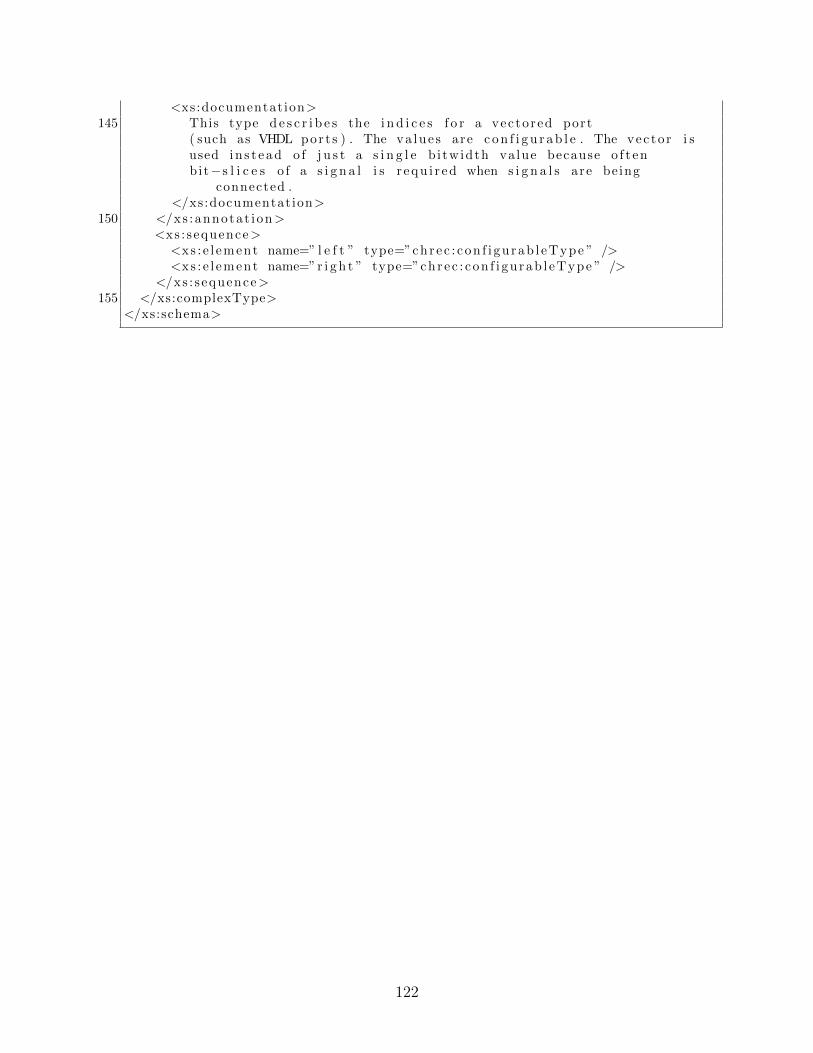
<xs:documentation>145 This type d e s c r i b e s the i n d i c e s f o r a vectored port
( such as VHDL port s ) . The va lues are c o n f i g u r a b l e . The vec tor i sused in s t ead o f j u s t a s i n g l e b i twidth value because o f t enbit−s l i c e s o f a s i g n a l i s r equ i r ed when s i g n a l s are being
connected .</xs:documentation>
150 </xs :annotat ion><xs : sequence>
<xs : e l ement name=” l e f t ” type=”chrec : con f i gu rab l eType ” /><xs : e l ement name=”r i g h t ” type=”chrec : con f i gu rab l eType ” />
</xs : sequence>155 </xs:complexType>
</xs:schema>
122

Appendix D
Generated VHDL from Ogre
This appendix contains the top-level VHDL and the FSM for a radio design that weregenerated by the Ogre system discussed in Chapter 5. Pains were taken in the Ogre systemto create human-readable VHDL as demonstrate by the files below.
D.1 Top-Level VHDL
vhdl/chrec qpsk S15 mod.vhd
l ibrary i e e e ;use i e e e . s t d l o g i c 1 1 6 4 . a l l ;use i e e e . numer ic std . a l l ;
4entity chrec qpsk S15 mod i s
port (c l k : in s t d l o g i c ;r e a l i n : in s t d l o g i c v e c t o r (11 downto 0) ;
9 r s t : in s t d l o g i c ;v a l i d I n : in s t d l o g i c ;imag in : in s t d l o g i c v e c t o r (11 downto 0) ;y1 : out s t d l o g i c v e c t o r (11 downto 0) ;s t robe : out s t d l o g i c ;
14 x1 : out s t d l o g i c v e c t o r (11 downto 0) ;dec y : out s t d l o g i c v e c t o r (1 downto 0) ;dec x : out s t d l o g i c v e c t o r (1 downto 0)) ;
end chrec qpsk S15 mod ;19
architecture Generated of chrec qpsk S15 mod i s
24 component s i g t o s l v i sgeneric (
WIDTH : i n t e g e r := 8) ;
port (29 s i g I n : in s igned (WIDTH − 1 downto 0) ;
slvOut : out s t d l o g i c v e c t o r (WIDTH − 1 downto 0)) ;
end component ;
34
123

component decis ionParam i sgeneric (
RADIO TYPE : i n t e g e r := 2) ;
39 port (y : in s igned ;x : in s igned ;d e c i s i o n y : out s igned ;d e c i s i o n x : out s igned
44 ) ;end component ;
component nco v2 0 i s49 generic (
SAMPLES PER SYMBOL : i n t e g e r := 2) ;
port (r s t : in s t d l o g i c ;
54 x : in s igned ;c l k : in s t d l o g i c ;v a l i d I n : in s t d l o g i c ;ce : in s t d l o g i c ;mu : out unsigned ;
59 s t robe : out s t d l o g i c) ;
end component ;
64 component regEnSigned i sgeneric (
width : i n t e g e r := 8) ;
port (69 c l k : in s t d l o g i c ;
en : in s t d l o g i c ;d : in s igned ( width − 1 downto 0) ;r s t : in s t d l o g i c ;q : out s igned ( width − 1 downto 0)
74 ) ;end component ;
component s l v t o s i g i s79 generic (
WIDTH : i n t e g e r := 8) ;
port (s l v I n : in s t d l o g i c v e c t o r (WIDTH − 1 downto 0) ;
84 sigOut : out s igned (WIDTH − 1 downto 0)) ;
end component ;
124

89 component l o o p f i l t e r l a t 2 v 2 0 i sgeneric (
kPrec i s i on : i n t e g e r := 44 ;phaseDetectorGain : r e a l := 6 . 0 ;samplesPerSymbol : i n t e g e r := 2 ;
94 accumulationWidth : i n t e g e r := 32 ;order : i n t e g e r := 2 ;loopBandwidth : r e a l := 0 . 0 1 ;loopDampingFactor : r e a l := 1 . 0 ;DDSGain : r e a l := −1.0
99 ) ;port (
e r r o r I n : in s igned ;c l k : in s t d l o g i c ;ce : in s t d l o g i c ;
104 v a l i d I n : in s t d l o g i c ;r s t : in s t d l o g i c ;e s t imate : out s igned ( accumulationWidth downto 0)) ;
end component ;109
component calculateMu i sgeneric (
samplesPerSymbol : i n t e g e r := 2114 ) ;
port (v a l i d I n : in s t d l o g i c ;c l k : in s t d l o g i c ;r s t : in s t d l o g i c ;
119 ce : in s t d l o g i c ;s t robe : in s t d l o g i c ;preMu : in unsigned ;mu : out unsigned) ;
124 end component ;
component DDS AdjustableFrequency i sgeneric (
129 phaseOf f s e t : r e a l := 0 . 0 ;romAddrWidth : i n t e g e r := 12 ;ga in : r e a l := 1 .0) ;
port (134 ce : in s t d l o g i c ;
r s t : in s t d l o g i c ;c l k : in s t d l o g i c ;v a l i d I n : in s t d l o g i c ;data : in s igned ;
139 cos : out s igned (17 downto 0) ;s i n : out s igned (17 downto 0)) ;
end component ;
125

144component i n t e r p o l a t o r c u b i c 1 2 d s p 4 8 s p i p e d i s
port (ce : in s t d l o g i c ;x : in s igned ;
149 r s t : in s t d l o g i c ;mu : in unsigned ;c l k : in s t d l o g i c ;v a l i d I n : in s t d l o g i c ;y : out s igned
154 ) ;end component ;
component s i g n e d f i x e d p o i n t r e s i z e i s159 generic (
output l ength : i n t e g e r := 12 ;o u t p u t i n t e g r a l b i t s : i n t e g e r := 2 ;i n p u t i n t e g r a l b i t s : i n t e g e r := 2 ;i nput l eng th : i n t e g e r := 12
164 ) ;port (
x : in s igned ( input l eng th − 1 downto 0) ;y : out s igned ( output l ength − 1 downto 0)) ;
169 end component ;
component ped i sport (
174 d e c i s i o n y : in s igned ;x : in s igned ;y : in s igned ;s t robe : in s t d l o g i c ;d e c i s i o n x : in s igned ;
179 phaseError : out s igned) ;
end component ;
184 component regEnStdLogic i sport (
en : in s t d l o g i c ;c l k : in s t d l o g i c ;d : in s t d l o g i c ;
189 r s t : in s t d l o g i c ;q : out s t d l o g i c) ;
end component ;
194component TED zero c ro s s ing l a t1 v2 0 i s
generic (
126

samplesPerSymbol : i n t e g e r := 2 ;numOfInputs : i n t e g e r := 2
199 ) ;port (
d e c i s i o n y : in s igned ;c l k : in s t d l o g i c ;d e c i s i o n x : in s igned ;
204 ce : in s t d l o g i c ;x : in s igned ;y : in s igned ;r s t : in s t d l o g i c ;s t robe : in s t d l o g i c ;
209 v a l i d I n : in s t d l o g i c ;t imingError : out s igned) ;
end component ;
214component chrec qpsk S15 mod FSM i s
port (v a l i d I n : in s t d l o g i c ;r s t : in s t d l o g i c ;
219 c l k : in s t d l o g i c ;reg1EN : out s t d l o g i c ;phase f i l terVALIDIN : out s t d l o g i c ;dec x regEN : out s t d l o g i c ;t i m i n g f i l t e r C E : out s t d l o g i c ;
224 x interpolatorVALIDIN : out s t d l o g i c ;ncoVALIDIN : out s t d l o g i c ;x inte rpo la torCE : out s t d l o g i c ;y1RegEN : out s t d l o g i c ;dec y regEN : out s t d l o g i c ;
229 reg2EN : out s t d l o g i c ;reg4EN : out s t d l o g i c ;calculateMuVALIDIN : out s t d l o g i c ;TEDVALIDIN : out s t d l o g i c ;DDSCE : out s t d l o g i c ;
234 reg3EN : out s t d l o g i c ;strobe regEN : out s t d l o g i c ;y interpolatorVALIDIN : out s t d l o g i c ;reg6EN : out s t d l o g i c ;t iming f i l terVALIDIN : out s t d l o g i c ;
239 TEDCE : out s t d l o g i c ;ncoCE : out s t d l o g i c ;y inte rpo la torCE : out s t d l o g i c ;p h a s e f i l t e r C E : out s t d l o g i c ;reg5EN : out s t d l o g i c ;
244 x1RegEN : out s t d l o g i c ;calculateMuCE : out s t d l o g i c ;DDSVALIDIN : out s t d l o g i c) ;
end component ;249
127

component cwRotation i sport (
x : in s igned ;254 y : in s igned ;
s i n : in s igned ;cos : in s igned ;y out : out s igned ;x out : out s igned
259 ) ;end component ;
signal y1Reg q y1 inReg : s igned (11 downto 0) ;signal r e g 4 q r e s i z e 2 x : s igned (12 downto 0) ;
264 signal r e a l i n o u t R e g r e a l i n c o n v e r t e r s l v I n : s t d l o g i c v e c t o r (11downto 0) ;
signal imag in outReg cwRotat ion y : s igned (11 downto 0) ;signal r s t o u t R e g n c o r s t : s t d l o g i c ;signal FSM x inte rpo l a to rCE x in t e rpo l a to r c e : s t d l o g i c ;signal FSM reg5EN reg5 en : s t d l o g i c ;
269 signal FSM DDSVALIDIN DDS validIn : s t d l o g i c ;signal reg5 q DDS data : s igned (18 downto 0) ;signal ca lcu lateMu mu y interpo lator mu : unsigned (16 downto 0) ;signal r eg6 q nco x : s igned (17 downto 0) ;signal nco mu calculateMu preMu : unsigned (17 downto 0) ;
274 signal de c y r eg q dec y inR eg : s igned (1 downto 0) ;signal d e c i s i o n d e c i s i o n x r e s i z e 3 x : s igned (11 downto 0) ;signal s t r o b e r e g q s t r o b e i n R e g : s t d l o g i c ;signal FSM reg1EN reg1 en : s t d l o g i c ;signal FSM t im ing f i l t e rVALIDIN t im ing f i l t e r va l i d In : s t d l o g i c ;
279 signal FSM TEDCE TED ce : s t d l o g i c ;signal val idIn outReg FSM val idIn : s t d l o g i c ;signal FSM reg2EN reg2 en : s t d l o g i c ;signal r e s i z e 3 y d e c x r e g d : s igned (1 downto 0) ;signal ped phaseError reg4 d : s igned (12 downto 0) ;
284 signal FSM calculateMuCE calculateMu ce : s t d l o g i c ;signal FSM dec x regEN dec x reg en : s t d l o g i c ;signal dec yconve r t e r s l vOut dec y inReg : s t d l o g i c v e c t o r (1 downto 0)
;signal FSM y1RegEN y1Reg en : s t d l o g i c ;signal de c x r eg q dec x inR eg : s igned (1 downto 0) ;
289 signal FSM reg4EN reg4 en : s t d l o g i c ;signal t i m i n g f i l t e r e s t i m a t e r e s i z e 1 x : s igned (18 downto 0) ;signal dec xconve r t e r s l vOut dec x inReg : s t d l o g i c v e c t o r (1 downto 0)
;signal y1conver te r s lvOut y1 inReg : s t d l o g i c v e c t o r (11 downto 0) ;signal DDS sin cwRotat ion s in : s i gned (17 downto 0) ;
294 signal F S M p h a s e f i l t e r C E p h a s e f i l t e r c e : s t d l o g i c ;signal FSM reg3EN reg3 en : s t d l o g i c ;signal p h a s e f i l t e r e s t i m a t e r e g 5 d : s igned (18 downto 0) ;signal imag in ou tReg imag inconve r t e r s l v In : s t d l o g i c v e c t o r (11
downto 0) ;signal FSM y interpo latorVALIDIN y interpo lator va l id In : s t d l o g i c ;
299 signal FSM calculateMuVALIDIN calculateMu validIn : s t d l o g i c ;signal FSM phase f i l t e rVALIDIN phase f i l t e r va l i d In : s t d l o g i c ;
128

signal FSM ncoVALIDIN nco validIn : s t d l o g i c ;signal n c o s t r o b e c a l cu l a t eM u s t r o b e : s t d l o g i c ;signal FSM DDSCE DDS ce : s t d l o g i c ;
304 signal DDS cos cwRotation cos : s i gned (17 downto 0) ;signal cwRotat ion y out reg2 d : s igned (11 downto 0) ;signal cwRotat ion x out reg1 d : s igned (11 downto 0) ;signal c l k ou tReg nco c l k : s t d l o g i c ;signal x i n t e r p o l a t o r y d e c i s i o n x : s igned (11 downto 0) ;
309 signal FSM x interpo latorVALIDIN x interpo lator va l id In : s t d l o g i c ;signal F S M t i m i n g f i l t e r C E t i m i n g f i l t e r c e : s t d l o g i c ;signal FSM ncoCE nco ce : s t d l o g i c ;signal r e g 1 q x i n t e r p o l a t o r x : s igned (11 downto 0) ;signal r e g 2 q y i n t e r p o l a t o r x : s igned (11 downto 0) ;
314 signal r e s i z e 4 y d e c y r e g d : s igned (1 downto 0) ;signal x1conver te r s lvOut x1 inReg : s t d l o g i c v e c t o r (11 downto 0) ;signal d e c i s i o n d e c i s i o n y r e s i z e 4 x : s igned (11 downto 0) ;signal r e s i z e 1 y r e g 6 d : s igned (17 downto 0) ;signal TED timingError reg3 d : s igned (11 downto 0) ;
319 signal FSM y inte rpo l a to rCE y in t e rpo l a to r c e : s t d l o g i c ;signal FSM TEDVALIDIN TED validIn : s t d l o g i c ;signal FSM x1RegEN x1Reg en : s t d l o g i c ;signal FSM strobe regEN strobe reg en : s t d l o g i c ;signal FSM dec y regEN dec y reg en : s t d l o g i c ;
324 signal r e g 3 q t i m i n g f i l t e r e r r o r I n : s i gned (11 downto 0) ;signal r ea l in outReg cwRotat i on x : s igned (11 downto 0) ;signal FSM reg6EN reg6 en : s t d l o g i c ;signal r e s i z e 2 y p h a s e f i l t e r e r r o r I n : s igned (14 downto 0) ;signal y i n t e r po l a t o r y y 1R e g d : s igned (11 downto 0) ;
329 signal x1Reg q x1 inReg : s igned (11 downto 0) ;begin
dec yconve r t e r : s i g t o s l vgeneric map(
334 WIDTH => 2)port map(
s i g I n => dec y reg q dec y inReg ,slvOut => dec yconve r t e r s l vOut dec y inReg
339 ) ;
d e c i s i o n : decis ionParamgeneric map(
RADIO TYPE => 4344 )
port map(d e c i s i o n x => d e c i s i o n d e c i s i o n x r e s i z e 3 x ,x => x i n t e r p o l a t o r y d e c i s i o n x ,d e c i s i o n y => d e c i s i o n d e c i s i o n y r e s i z e 4 x ,
349 y => y i n t e r po l a t o r y y 1R e g d) ;
nco : nco v2 0generic map(
354 SAMPLES PER SYMBOL => 2
129

)port map(
r s t => r s t ou tReg nco r s t ,x => reg6 q nco x ,
359 mu => nco mu calculateMu preMu ,v a l i d I n => FSM ncoVALIDIN nco validIn ,s t robe => nco s t robe ca l cu l a t eMu s t robe ,c l k => c lk outReg nco c lk ,ce => FSM ncoCE nco ce
364 ) ;
y1Reg : regEnSignedgeneric map(
width => 12369 )
port map(q => y1Reg q y1 inReg ,r s t => r s t ou tReg nco r s t ,en => FSM y1RegEN y1Reg en ,
374 c l k => c lk outReg nco c lk ,d => y i n t e r po l a t o r y y 1R e g d
) ;
r e a l i n c o n v e r t e r : s l v t o s i g379 generic map(
WIDTH => 12)port map(
s l v I n => r e a l i n o u t R e g r e a l i n c o n v e r t e r s l v I n ,384 sigOut => r ea l in outReg cwRotat i on x
) ;
p h a s e f i l t e r : l o o p f i l t e r l a t 2 v 2 0generic map(
389 phaseDetectorGain => 2 . 0 ,kPre c i s i on => 35 ,samplesPerSymbol => 2 ,accumulationWidth => 18 ,order => 2 ,
394 loopBandwidth => 0 . 03 ,loopDampingFactor => 1 . 0 ,DDSGain => 1 .0
)port map(
399 r s t => r s t ou tReg nco r s t ,ce => F S M p h a s e f i l t e r C E p h a s e f i l t e r c e ,e s t imate => p h a s e f i l t e r e s t i m a t e r e g 5 d ,v a l i d I n => FSM phase f i l t e rVALIDIN phase f i l t e r va l id In ,c l k => c lk outReg nco c lk ,
404 e r r o r I n => r e s i z e 2 y p h a s e f i l t e r e r r o r I n) ;
calculateMu1 : calculateMugeneric map(
130

409 samplesPerSymbol => 2)port map(
r s t => r s t ou tReg nco r s t ,mu => ca lcu lateMu mu y interpo lator mu ,
414 preMu => nco mu calculateMu preMu ,ce => FSM calculateMuCE calculateMu ce ,v a l i d I n => FSM calculateMuVALIDIN calculateMu validIn ,s t robe => nco s t robe ca l cu l a t eMu s t robe ,c l k => c l k ou tReg nco c l k
419 ) ;
x1conver ter : s i g t o s l vgeneric map(
WIDTH => 12424 )
port map(slvOut => x1converter s lvOut x1 inReg ,s i g I n => x1Reg q x1 inReg
) ;429
t i m i n g f i l t e r : l o o p f i l t e r l a t 2 v 2 0generic map(
phaseDetectorGain => 6 . 0 ,kPre c i s i on => 35 ,
434 samplesPerSymbol => 2 ,accumulationWidth => 18 ,order => 2 ,loopBandwidth => 0 . 01 ,loopDampingFactor => 1 . 0 ,
439 DDSGain => −1.0)port map(
r s t => r s t ou tReg nco r s t ,v a l i d I n => FSM t iming f i l t e rVALIDIN t im ing f i l t e r va l i d In ,
444 es t imate => t i m i n g f i l t e r e s t i m a t e r e s i z e 1 x ,c l k => c lk outReg nco c lk ,ce => F S M t i m i n g f i l t e r C E t i m i n g f i l t e r c e ,e r r o r I n => r e g 3 q t i m i n g f i l t e r e r r o r I n
) ;449
DDS : DDS AdjustableFrequencygeneric map(
phaseOf f s e t => 0 . 0 ,ga in => 1 . 0 ,
454 romAddrWidth => 12)port map(
r s t => r s t ou tReg nco r s t ,v a l i d I n => FSM DDSVALIDIN DDS validIn ,
459 data => reg5 q DDS data ,s i n => DDS sin cwRotation sin ,ce => FSM DDSCE DDS ce ,cos => DDS cos cwRotation cos ,
131

c l k => c l k ou tReg nco c l k464 ) ;
d e c y r eg : regEnSignedgeneric map(
width => 2469 )
port map(r s t => r s t ou tReg nco r s t ,q => dec y reg q dec y inReg ,c l k => c lk outReg nco c lk ,
474 d => r e s i z e 4 y d e c y r e g d ,en => FSM dec y regEN dec y reg en
) ;
x i n t e r p o l a t o r : i n t e r p o l a t o r c u b i c 1 2 d s p 4 8 s p i p e d479 port map(
r s t => r s t ou tReg nco r s t ,ce => FSM x inte rpo la to rCE x inte rpo la to r ce ,mu => ca lcu lateMu mu y interpo lator mu ,c l k => c lk outReg nco c lk ,
484 y => x i n t e r p o l a t o r y d e c i s i o n x ,v a l i d I n => FSM x interpo latorVALIDIN x interpo lator va l id In ,x => r e g 1 q x i n t e r p o l a t o r x
) ;
489 reg6 : regEnSignedgeneric map(
width => 18)port map(
494 r s t => r s t ou tReg nco r s t ,q => reg6 q nco x ,c l k => c lk outReg nco c lk ,d => r e s i z e 1 y r e g 6 d ,en => FSM reg6EN reg6 en
499 ) ;
x1Reg : regEnSignedgeneric map(
width => 12504 )
port map(r s t => r s t ou tReg nco r s t ,c l k => c lk outReg nco c lk ,d => x i n t e r p o l a t o r y d e c i s i o n x ,
509 en => FSM x1RegEN x1Reg en ,q => x1Reg q x1 inReg
) ;
y i n t e r p o l a t o r : i n t e r p o l a t o r c u b i c 1 2 d s p 4 8 s p i p e d514 port map(
r s t => r s t ou tReg nco r s t ,mu => ca lcu lateMu mu y interpo lator mu ,
132

v a l i d I n => FSM y interpo latorVALIDIN y interpo lator va l id In ,c l k => c lk outReg nco c lk ,
519 x => r e g 2 q y i n t e r p o l a t o r x ,ce => FSM y inte rpo la to rCE y inte rpo la to r ce ,y => y i n t e r po l a t o r y y 1R e g d
) ;
524 r e s i z e 4 : s i g n e d f i x e d p o i n t r e s i z egeneric map(
output l ength => 2 ,i nput l eng th => 12 ,i n p u t i n t e g r a l b i t s => 2 ,
529 o u t p u t i n t e g r a l b i t s => 2)port map(
y => r e s i z e 4 y d e c y r e g d ,x => d e c i s i o n d e c i s i o n y r e s i z e 4 x
534 ) ;
ped1 : pedport map(
d e c i s i o n x => r e s i z e 3 y d e c x r e g d ,539 phaseError => ped phaseError reg4 d ,
s t robe => nco s t robe ca l cu l a t eMu s t robe ,x => x i n t e r p o l a t o r y d e c i s i o n x ,d e c i s i o n y => r e s i z e 4 y d e c y r e g d ,y => y i n t e r po l a t o r y y 1R e g d
544 ) ;
r e s i z e 2 : s i g n e d f i x e d p o i n t r e s i z egeneric map(
output l ength => 15 ,549 input l eng th => 13 ,
i n p u t i n t e g r a l b i t s => 1 ,o u t p u t i n t e g r a l b i t s => 3
)port map(
554 x => r e g 4 q r e s i z e 2 x ,y => r e s i z e 2 y p h a s e f i l t e r e r r o r I n
) ;
r e s i z e 3 : s i g n e d f i x e d p o i n t r e s i z e559 generic map(
output l ength => 2 ,i nput l eng th => 12 ,i n p u t i n t e g r a l b i t s => 2 ,o u t p u t i n t e g r a l b i t s => 2
564 )port map(
x => d e c i s i o n d e c i s i o n x r e s i z e 3 x ,y => r e s i z e 3 y d e c x r e g d
) ;569
dec xconve r t e r : s i g t o s l v
133

generic map(WIDTH => 2
)574 port map(
s i g I n => dec x reg q dec x inReg ,slvOut => dec xconve r t e r s l vOut dec x inReg
) ;
579 r e s i z e 1 : s i g n e d f i x e d p o i n t r e s i z egeneric map(
output l ength => 18 ,i nput l eng th => 19 ,i n p u t i n t e g r a l b i t s => 1 ,
584 o u t p u t i n t e g r a l b i t s => 0)port map(
x => t i m i n g f i l t e r e s t i m a t e r e s i z e 1 x ,y => r e s i z e 1 y r e g 6 d
589 ) ;
reg2 : regEnSignedgeneric map(
width => 12594 )
port map(r s t => r s t ou tReg nco r s t ,en => FSM reg2EN reg2 en ,d => cwRotat ion y out reg2 d ,
599 c l k => c lk outReg nco c lk ,q => r e g 2 q y i n t e r p o l a t o r x
) ;
reg3 : regEnSigned604 generic map(
width => 12)port map(
r s t => r s t ou tReg nco r s t ,609 en => FSM reg3EN reg3 en ,
c l k => c lk outReg nco c lk ,d => TED timingError reg3 d ,q => r e g 3 q t i m i n g f i l t e r e r r o r I n
) ;614
s t r o b e r e g : regEnStdLogicport map(
r s t => r s t ou tReg nco r s t ,q => s t r o b e r e g q s t r o b e i n R e g ,
619 d => nco s t robe ca l cu l a t eMu s t robe ,c l k => c lk outReg nco c lk ,en => FSM strobe regEN strobe reg en
) ;
624 reg4 : regEnSigned
134

generic map(width => 13
)port map(
629 q => r e g 4 q r e s i z e 2 x ,r s t => r s t ou tReg nco r s t ,d => ped phaseError reg4 d ,en => FSM reg4EN reg4 en ,c l k => c l k ou tReg nco c l k
634 ) ;
reg5 : regEnSignedgeneric map(
width => 19639 )
port map(r s t => r s t ou tReg nco r s t ,en => FSM reg5EN reg5 en ,q => reg5 q DDS data ,
644 d => p h a s e f i l t e r e s t i m a t e r e g 5 d ,c l k => c l k ou tReg nco c l k
) ;
y1conver ter : s i g t o s l v649 generic map(
WIDTH => 12)port map(
s i g I n => y1Reg q y1 inReg ,654 slvOut => y1conver te r s lvOut y1 inReg
) ;
TED : TED ze ro c ro s s ing l a t1 v2 0generic map(
659 numOfInputs => 2 ,samplesPerSymbol => 2
)port map(
r s t => r s t ou tReg nco r s t ,664 ce => FSM TEDCE TED ce ,
d e c i s i o n x => r e s i z e 3 y d e c x r e g d ,s t robe => nco s t robe ca l cu l a t eMu s t robe ,c l k => c lk outReg nco c lk ,x => x i n t e r p o l a t o r y d e c i s i o n x ,
669 d e c i s i o n y => r e s i z e 4 y d e c y r e g d ,t imingError => TED timingError reg3 d ,v a l i d I n => FSM TEDVALIDIN TED validIn ,y => y i n t e r po l a t o r y y 1R e g d
) ;674
reg1 : regEnSignedgeneric map(
width => 12)
135

679 port map(r s t => r s t ou tReg nco r s t ,en => FSM reg1EN reg1 en ,d => cwRotat ion x out reg1 d ,c l k => c lk outReg nco c lk ,
684 q => r e g 1 q x i n t e r p o l a t o r x) ;
FSM : chrec qpsk S15 mod FSMport map(
689 r s t => r s t ou tReg nco r s t ,x inte rpo la torCE => FSM x inte rpo la to rCE x inte rpo la to r ce ,reg5EN => FSM reg5EN reg5 en ,DDSVALIDIN => FSM DDSVALIDIN DDS validIn ,reg1EN => FSM reg1EN reg1 en ,
694 t iming f i l terVALIDIN =>FSM t iming f i l t e rVALIDIN t im ing f i l t e r va l i d In ,
TEDCE => FSM TEDCE TED ce ,v a l i d I n => val idIn outReg FSM val idIn ,reg2EN => FSM reg2EN reg2 en ,calculateMuCE => FSM calculateMuCE calculateMu ce ,
699 dec x regEN => FSM dec x regEN dec x reg en ,y1RegEN => FSM y1RegEN y1Reg en ,reg4EN => FSM reg4EN reg4 en ,p h a s e f i l t e r C E => F S M p h a s e f i l t e r C E p h a s e f i l t e r c e ,reg3EN => FSM reg3EN reg3 en ,
704 y interpolatorVALIDIN =>FSM y interpo latorVALIDIN y interpo lator va l id In ,
calculateMuVALIDIN => FSM calculateMuVALIDIN calculateMu validIn ,phase f i l terVALIDIN => FSM phase f i l t e rVALIDIN phase f i l t e r va l id In ,ncoVALIDIN => FSM ncoVALIDIN nco validIn ,DDSCE => FSM DDSCE DDS ce ,
709 c l k => c lk outReg nco c lk ,x interpolatorVALIDIN =>
FSM x interpo latorVALIDIN x interpo lator va l id In ,t i m i n g f i l t e r C E => F S M t i m i n g f i l t e r C E t i m i n g f i l t e r c e ,ncoCE => FSM ncoCE nco ce ,y inte rpo la torCE => FSM y inte rpo la to rCE y inte rpo la to r ce ,
714 TEDVALIDIN => FSM TEDVALIDIN TED validIn ,x1RegEN => FSM x1RegEN x1Reg en ,strobe regEN => FSM strobe regEN strobe reg en ,dec y regEN => FSM dec y regEN dec y reg en ,reg6EN => FSM reg6EN reg6 en
719 ) ;
d e c x r eg : regEnSignedgeneric map(
width => 2724 )
port map(r s t => r s t ou tReg nco r s t ,d => r e s i z e 3 y d e c x r e g d ,en => FSM dec x regEN dec x reg en ,
729 q => dec x reg q dec x inReg ,
136

c l k => c l k ou tReg nco c l k) ;
imag inconver t e r : s l v t o s i g734 generic map(
WIDTH => 12)port map(
s igOut => imag in outReg cwRotat ion y ,739 s l v I n => imag in ou tReg imag inconve r t e r s l v In
) ;
cwRotation1 : cwRotationport map(
744 y => imag in outReg cwRotat ion y ,s i n => DDS sin cwRotation sin ,cos => DDS cos cwRotation cos ,y out => cwRotat ion y out reg2 d ,x out => cwRotat ion x out reg1 d ,
749 x => r ea l in outReg cwRotat i on x) ;
r e a l i n o u t R e g r e a l i n c o n v e r t e r s l v I n <= r e a l i n ;r s t o u t R e g n c o r s t <= r s t ;
754 s t robe <= s t r o b e r e g q s t r o b e i n R e g ;va l idIn outReg FSM val idIn <= v a l i d I n ;dec y <= dec yconve r t e r s l vOut dec y inReg ;dec x <= dec xconve r t e r s l vOut dec x inReg ;y1 <= y1conver te r s lvOut y1 inReg ;
759 imag in ou tReg imag inconve r t e r s l v In <= imag in ;c l k ou tReg nco c l k <= c lk ;x1 <= x1conver te r s lvOut x1 inReg ;
end Generated ;
D.2 Finite State Machine
vhdl/chrec qpsk S15 mod FSM.vhd
1 l ibrary i e e e ;use i e e e . s t d l o g i c 1 1 6 4 . a l l ;
entity chrec qpsk S15 mod FSM i sport (
6 c l k : in s t d l o g i c ;r s t : in s t d l o g i c ;v a l i d I n : in s t d l o g i c ;y inte rpo la torCE : out s t d l o g i c ;TEDVALIDIN : out s t d l o g i c ;
11 reg6EN : out s t d l o g i c ;y1RegEN : out s t d l o g i c ;TEDCE : out s t d l o g i c ;DDSVALIDIN : out s t d l o g i c ;
137

reg1EN : out s t d l o g i c ;16 y interpolatorVALIDIN : out s t d l o g i c ;
ncoCE : out s t d l o g i c ;p h a s e f i l t e r C E : out s t d l o g i c ;x inte rpo la torCE : out s t d l o g i c ;calculateMuVALIDIN : out s t d l o g i c ;
21 phase f i l terVALIDIN : out s t d l o g i c ;dec y regEN : out s t d l o g i c ;t i m i n g f i l t e r C E : out s t d l o g i c ;dec x regEN : out s t d l o g i c ;reg5EN : out s t d l o g i c ;
26 DDSCE : out s t d l o g i c ;calculateMuCE : out s t d l o g i c ;strobe regEN : out s t d l o g i c ;ncoVALIDIN : out s t d l o g i c ;reg3EN : out s t d l o g i c ;
31 reg2EN : out s t d l o g i c ;t iming f i l terVALIDIN : out s t d l o g i c ;x1RegEN : out s t d l o g i c ;x interpolatorVALIDIN : out s t d l o g i c ;reg4EN : out s t d l o g i c
36 ) ;end chrec qpsk S15 mod FSM ;
architecture behav io ra l of chrec qpsk S15 mod FSM i s41
type s t a t e t y p e i s ( s t a t e 0 , s t a t e 1 , s t a t e 2 , s t a t e 3 , s t a t e 4 , s t a t e 5, s t a t e 6 , s t a t e 7 , s t a t e 8 , s t a t e 9 , s ta t e 10 , s ta t e 11 , s ta t e 12 ,s ta t e 13 , s ta t e 14 , s t a t e 1 5 ) ;
signal cs : s t a t e t y p e ;signal ns : s t a t e t y p e ;
begin46
process ( c lk , ns , r s t ) i sbegin
i f r s t = ’1 ’ thencs <= s t a t e 1 5 ;
51 e l s i f r i s i n g e d g e ( c l k ) thencs <= ns ;
end i f ;end process ;
56 process ( cs , v a l i d I n ) i sbegin
ns <= s t a t e 1 5 ;y inte rpo la torCE <= ’ 0 ’ ;TEDVALIDIN <= ’ 0 ’ ;
61 reg6EN <= ’ 0 ’ ;y1RegEN <= ’ 0 ’ ;TEDCE <= ’ 0 ’ ;DDSVALIDIN <= ’ 0 ’ ;reg1EN <= ’ 0 ’ ;
66 y interpolatorVALIDIN <= ’ 0 ’ ;
138

ncoCE <= ’ 0 ’ ;p h a s e f i l t e r C E <= ’ 0 ’ ;x inte rpo la torCE <= ’ 0 ’ ;calculateMuVALIDIN <= ’ 0 ’ ;
71 phase f i l terVALIDIN <= ’ 0 ’ ;dec y regEN <= ’ 0 ’ ;t i m i n g f i l t e r C E <= ’ 0 ’ ;dec x regEN <= ’ 0 ’ ;reg5EN <= ’ 0 ’ ;
76 DDSCE <= ’ 0 ’ ;calculateMuCE <= ’ 0 ’ ;strobe regEN <= ’ 0 ’ ;ncoVALIDIN <= ’ 0 ’ ;reg3EN <= ’ 0 ’ ;
81 reg2EN <= ’ 0 ’ ;t iming f i l terVALIDIN <= ’ 0 ’ ;x1RegEN <= ’ 0 ’ ;x interpolatorVALIDIN <= ’ 0 ’ ;reg4EN <= ’ 0 ’ ;
86 case cs i swhen s t a t e 0 =>
y inte rpo la torCE <= ’ 0 ’ ;TEDVALIDIN <= ’ 0 ’ ;reg6EN <= ’ 0 ’ ;
91 y1RegEN <= ’ 0 ’ ;TEDCE <= ’ 0 ’ ;DDSVALIDIN <= ’ 0 ’ ;reg1EN <= ’ 1 ’ ;y interpolatorVALIDIN <= ’ 0 ’ ;
96 ncoCE <= ’ 0 ’ ;p h a s e f i l t e r C E <= ’ 0 ’ ;x inte rpo la torCE <= ’ 0 ’ ;calculateMuVALIDIN <= ’ 1 ’ ;phase f i l terVALIDIN <= ’ 0 ’ ;
101 dec y regEN <= ’ 0 ’ ;t i m i n g f i l t e r C E <= ’ 0 ’ ;dec x regEN <= ’ 0 ’ ;reg5EN <= ’ 0 ’ ;DDSCE <= ’ 0 ’ ;
106 calculateMuCE <= ’ 1 ’ ;strobe regEN <= ’ 1 ’ ;ncoVALIDIN <= ’ 0 ’ ;reg3EN <= ’ 0 ’ ;reg2EN <= ’ 1 ’ ;
111 t iming f i l terVALIDIN <= ’ 0 ’ ;x1RegEN <= ’ 0 ’ ;x interpolatorVALIDIN <= ’ 0 ’ ;reg4EN <= ’ 0 ’ ;ns <= s t a t e 1 ;
116 when s t a t e 1 =>y inte rpo la torCE <= ’ 1 ’ ;TEDVALIDIN <= ’ 0 ’ ;reg6EN <= ’ 0 ’ ;y1RegEN <= ’ 0 ’ ;
139

121 TEDCE <= ’ 0 ’ ;DDSVALIDIN <= ’ 0 ’ ;reg1EN <= ’ 0 ’ ;y interpolatorVALIDIN <= ’ 1 ’ ;ncoCE <= ’ 0 ’ ;
126 p h a s e f i l t e r C E <= ’ 0 ’ ;x inte rpo la torCE <= ’ 1 ’ ;calculateMuVALIDIN <= ’ 0 ’ ;phase f i l terVALIDIN <= ’ 0 ’ ;dec y regEN <= ’ 0 ’ ;
131 t i m i n g f i l t e r C E <= ’ 0 ’ ;dec x regEN <= ’ 0 ’ ;reg5EN <= ’ 0 ’ ;DDSCE <= ’ 0 ’ ;calculateMuCE <= ’ 0 ’ ;
136 strobe regEN <= ’ 0 ’ ;ncoVALIDIN <= ’ 0 ’ ;reg3EN <= ’ 0 ’ ;reg2EN <= ’ 0 ’ ;t iming f i l terVALIDIN <= ’ 0 ’ ;
141 x1RegEN <= ’ 0 ’ ;x interpolatorVALIDIN <= ’ 1 ’ ;reg4EN <= ’ 0 ’ ;ns <= s t a t e 2 ;
when s t a t e 2 =>146 y inte rpo la torCE <= ’ 1 ’ ;
TEDVALIDIN <= ’ 0 ’ ;reg6EN <= ’ 0 ’ ;y1RegEN <= ’ 0 ’ ;TEDCE <= ’ 0 ’ ;
151 DDSVALIDIN <= ’ 0 ’ ;reg1EN <= ’ 0 ’ ;y interpolatorVALIDIN <= ’ 0 ’ ;ncoCE <= ’ 0 ’ ;p h a s e f i l t e r C E <= ’ 0 ’ ;
156 x inte rpo la torCE <= ’ 1 ’ ;calculateMuVALIDIN <= ’ 0 ’ ;phase f i l terVALIDIN <= ’ 0 ’ ;dec y regEN <= ’ 0 ’ ;t i m i n g f i l t e r C E <= ’ 0 ’ ;
161 dec x regEN <= ’ 0 ’ ;reg5EN <= ’ 0 ’ ;DDSCE <= ’ 0 ’ ;calculateMuCE <= ’ 0 ’ ;strobe regEN <= ’ 0 ’ ;
166 ncoVALIDIN <= ’ 0 ’ ;reg3EN <= ’ 0 ’ ;reg2EN <= ’ 0 ’ ;t iming f i l terVALIDIN <= ’ 0 ’ ;x1RegEN <= ’ 0 ’ ;
171 x interpolatorVALIDIN <= ’ 0 ’ ;reg4EN <= ’ 0 ’ ;ns <= s t a t e 3 ;
when s t a t e 3 =>
140

y inte rpo la torCE <= ’ 1 ’ ;176 TEDVALIDIN <= ’ 0 ’ ;
reg6EN <= ’ 0 ’ ;y1RegEN <= ’ 0 ’ ;TEDCE <= ’ 0 ’ ;DDSVALIDIN <= ’ 0 ’ ;
181 reg1EN <= ’ 0 ’ ;y interpolatorVALIDIN <= ’ 0 ’ ;ncoCE <= ’ 0 ’ ;p h a s e f i l t e r C E <= ’ 0 ’ ;x inte rpo la torCE <= ’ 1 ’ ;
186 calculateMuVALIDIN <= ’ 0 ’ ;phase f i l terVALIDIN <= ’ 0 ’ ;dec y regEN <= ’ 0 ’ ;t i m i n g f i l t e r C E <= ’ 0 ’ ;dec x regEN <= ’ 0 ’ ;
191 reg5EN <= ’ 0 ’ ;DDSCE <= ’ 0 ’ ;calculateMuCE <= ’ 0 ’ ;strobe regEN <= ’ 0 ’ ;ncoVALIDIN <= ’ 0 ’ ;
196 reg3EN <= ’ 0 ’ ;reg2EN <= ’ 0 ’ ;t iming f i l terVALIDIN <= ’ 0 ’ ;x1RegEN <= ’ 0 ’ ;x interpolatorVALIDIN <= ’ 0 ’ ;
201 reg4EN <= ’ 0 ’ ;ns <= s t a t e 4 ;
when s t a t e 4 =>y inte rpo la torCE <= ’ 1 ’ ;TEDVALIDIN <= ’ 0 ’ ;
206 reg6EN <= ’ 0 ’ ;y1RegEN <= ’ 0 ’ ;TEDCE <= ’ 0 ’ ;DDSVALIDIN <= ’ 0 ’ ;reg1EN <= ’ 0 ’ ;
211 y interpolatorVALIDIN <= ’ 0 ’ ;ncoCE <= ’ 0 ’ ;p h a s e f i l t e r C E <= ’ 0 ’ ;x inte rpo la torCE <= ’ 1 ’ ;calculateMuVALIDIN <= ’ 0 ’ ;
216 phase f i l terVALIDIN <= ’ 0 ’ ;dec y regEN <= ’ 0 ’ ;t i m i n g f i l t e r C E <= ’ 0 ’ ;dec x regEN <= ’ 0 ’ ;reg5EN <= ’ 0 ’ ;
221 DDSCE <= ’ 0 ’ ;calculateMuCE <= ’ 0 ’ ;strobe regEN <= ’ 0 ’ ;ncoVALIDIN <= ’ 0 ’ ;reg3EN <= ’ 0 ’ ;
226 reg2EN <= ’ 0 ’ ;t iming f i l terVALIDIN <= ’ 0 ’ ;x1RegEN <= ’ 0 ’ ;
141
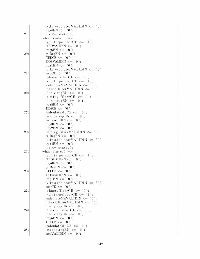
x interpolatorVALIDIN <= ’ 0 ’ ;reg4EN <= ’ 0 ’ ;
231 ns <= s t a t e 5 ;when s t a t e 5 =>
y inte rpo la torCE <= ’ 1 ’ ;TEDVALIDIN <= ’ 0 ’ ;reg6EN <= ’ 0 ’ ;
236 y1RegEN <= ’ 0 ’ ;TEDCE <= ’ 0 ’ ;DDSVALIDIN <= ’ 0 ’ ;reg1EN <= ’ 0 ’ ;y interpolatorVALIDIN <= ’ 0 ’ ;
241 ncoCE <= ’ 0 ’ ;p h a s e f i l t e r C E <= ’ 0 ’ ;x inte rpo la torCE <= ’ 1 ’ ;calculateMuVALIDIN <= ’ 0 ’ ;phase f i l terVALIDIN <= ’ 0 ’ ;
246 dec y regEN <= ’ 0 ’ ;t i m i n g f i l t e r C E <= ’ 0 ’ ;dec x regEN <= ’ 0 ’ ;reg5EN <= ’ 0 ’ ;DDSCE <= ’ 0 ’ ;
251 calculateMuCE <= ’ 0 ’ ;strobe regEN <= ’ 0 ’ ;ncoVALIDIN <= ’ 0 ’ ;reg3EN <= ’ 0 ’ ;reg2EN <= ’ 0 ’ ;
256 t iming f i l terVALIDIN <= ’ 0 ’ ;x1RegEN <= ’ 0 ’ ;x interpolatorVALIDIN <= ’ 0 ’ ;reg4EN <= ’ 0 ’ ;ns <= s t a t e 6 ;
261 when s t a t e 6 =>y inte rpo la torCE <= ’ 1 ’ ;TEDVALIDIN <= ’ 0 ’ ;reg6EN <= ’ 0 ’ ;y1RegEN <= ’ 0 ’ ;
266 TEDCE <= ’ 0 ’ ;DDSVALIDIN <= ’ 0 ’ ;reg1EN <= ’ 0 ’ ;y interpolatorVALIDIN <= ’ 0 ’ ;ncoCE <= ’ 0 ’ ;
271 p h a s e f i l t e r C E <= ’ 0 ’ ;x inte rpo la torCE <= ’ 1 ’ ;calculateMuVALIDIN <= ’ 0 ’ ;phase f i l terVALIDIN <= ’ 0 ’ ;dec y regEN <= ’ 0 ’ ;
276 t i m i n g f i l t e r C E <= ’ 0 ’ ;dec x regEN <= ’ 0 ’ ;reg5EN <= ’ 0 ’ ;DDSCE <= ’ 0 ’ ;calculateMuCE <= ’ 0 ’ ;
281 strobe regEN <= ’ 0 ’ ;ncoVALIDIN <= ’ 0 ’ ;
142

reg3EN <= ’ 0 ’ ;reg2EN <= ’ 0 ’ ;t iming f i l terVALIDIN <= ’ 0 ’ ;
286 x1RegEN <= ’ 0 ’ ;x interpolatorVALIDIN <= ’ 0 ’ ;reg4EN <= ’ 0 ’ ;ns <= s t a t e 7 ;
when s t a t e 7 =>291 y inte rpo la torCE <= ’ 1 ’ ;
TEDVALIDIN <= ’ 0 ’ ;reg6EN <= ’ 0 ’ ;y1RegEN <= ’ 0 ’ ;TEDCE <= ’ 0 ’ ;
296 DDSVALIDIN <= ’ 0 ’ ;reg1EN <= ’ 0 ’ ;y interpolatorVALIDIN <= ’ 0 ’ ;ncoCE <= ’ 0 ’ ;p h a s e f i l t e r C E <= ’ 0 ’ ;
301 x inte rpo la torCE <= ’ 1 ’ ;calculateMuVALIDIN <= ’ 0 ’ ;phase f i l terVALIDIN <= ’ 0 ’ ;dec y regEN <= ’ 0 ’ ;t i m i n g f i l t e r C E <= ’ 0 ’ ;
306 dec x regEN <= ’ 0 ’ ;reg5EN <= ’ 0 ’ ;DDSCE <= ’ 0 ’ ;calculateMuCE <= ’ 0 ’ ;strobe regEN <= ’ 0 ’ ;
311 ncoVALIDIN <= ’ 0 ’ ;reg3EN <= ’ 0 ’ ;reg2EN <= ’ 0 ’ ;t iming f i l terVALIDIN <= ’ 0 ’ ;x1RegEN <= ’ 0 ’ ;
316 x interpolatorVALIDIN <= ’ 0 ’ ;reg4EN <= ’ 0 ’ ;ns <= s t a t e 8 ;
when s t a t e 8 =>y inte rpo la torCE <= ’ 1 ’ ;
321 TEDVALIDIN <= ’ 0 ’ ;reg6EN <= ’ 0 ’ ;y1RegEN <= ’ 0 ’ ;TEDCE <= ’ 0 ’ ;DDSVALIDIN <= ’ 0 ’ ;
326 reg1EN <= ’ 0 ’ ;y interpolatorVALIDIN <= ’ 0 ’ ;ncoCE <= ’ 0 ’ ;p h a s e f i l t e r C E <= ’ 0 ’ ;x inte rpo la torCE <= ’ 1 ’ ;
331 calculateMuVALIDIN <= ’ 0 ’ ;phase f i l terVALIDIN <= ’ 0 ’ ;dec y regEN <= ’ 0 ’ ;t i m i n g f i l t e r C E <= ’ 0 ’ ;dec x regEN <= ’ 0 ’ ;
336 reg5EN <= ’ 0 ’ ;
143

DDSCE <= ’ 0 ’ ;calculateMuCE <= ’ 0 ’ ;strobe regEN <= ’ 0 ’ ;ncoVALIDIN <= ’ 0 ’ ;
341 reg3EN <= ’ 0 ’ ;reg2EN <= ’ 0 ’ ;t iming f i l terVALIDIN <= ’ 0 ’ ;x1RegEN <= ’ 0 ’ ;x interpolatorVALIDIN <= ’ 0 ’ ;
346 reg4EN <= ’ 0 ’ ;ns <= s t a t e 9 ;
when s t a t e 9 =>y inte rpo la torCE <= ’ 0 ’ ;TEDVALIDIN <= ’ 1 ’ ;
351 reg6EN <= ’ 0 ’ ;y1RegEN <= ’ 1 ’ ;TEDCE <= ’ 1 ’ ;DDSVALIDIN <= ’ 0 ’ ;reg1EN <= ’ 0 ’ ;
356 y interpolatorVALIDIN <= ’ 0 ’ ;ncoCE <= ’ 0 ’ ;p h a s e f i l t e r C E <= ’ 0 ’ ;x inte rpo la torCE <= ’ 0 ’ ;calculateMuVALIDIN <= ’ 0 ’ ;
361 phase f i l terVALIDIN <= ’ 0 ’ ;dec y regEN <= ’ 1 ’ ;t i m i n g f i l t e r C E <= ’ 0 ’ ;dec x regEN <= ’ 1 ’ ;reg5EN <= ’ 0 ’ ;
366 DDSCE <= ’ 0 ’ ;calculateMuCE <= ’ 0 ’ ;strobe regEN <= ’ 0 ’ ;ncoVALIDIN <= ’ 0 ’ ;reg3EN <= ’ 0 ’ ;
371 reg2EN <= ’ 0 ’ ;t iming f i l terVALIDIN <= ’ 0 ’ ;x1RegEN <= ’ 1 ’ ;x interpolatorVALIDIN <= ’ 0 ’ ;reg4EN <= ’ 1 ’ ;
376 ns <= s t a t e 1 0 ;when s t a t e 1 0 =>
y inte rpo la torCE <= ’ 0 ’ ;TEDVALIDIN <= ’ 0 ’ ;reg6EN <= ’ 0 ’ ;
381 y1RegEN <= ’ 0 ’ ;TEDCE <= ’ 0 ’ ;DDSVALIDIN <= ’ 0 ’ ;reg1EN <= ’ 0 ’ ;y interpolatorVALIDIN <= ’ 0 ’ ;
386 ncoCE <= ’ 0 ’ ;p h a s e f i l t e r C E <= ’ 1 ’ ;x inte rpo la torCE <= ’ 0 ’ ;calculateMuVALIDIN <= ’ 0 ’ ;phase f i l terVALIDIN <= ’ 1 ’ ;
144

391 dec y regEN <= ’ 0 ’ ;t i m i n g f i l t e r C E <= ’ 0 ’ ;dec x regEN <= ’ 0 ’ ;reg5EN <= ’ 0 ’ ;DDSCE <= ’ 0 ’ ;
396 calculateMuCE <= ’ 0 ’ ;strobe regEN <= ’ 0 ’ ;ncoVALIDIN <= ’ 0 ’ ;reg3EN <= ’ 1 ’ ;reg2EN <= ’ 0 ’ ;
401 t iming f i l terVALIDIN <= ’ 0 ’ ;x1RegEN <= ’ 0 ’ ;x interpolatorVALIDIN <= ’ 0 ’ ;reg4EN <= ’ 0 ’ ;ns <= s t a t e 1 1 ;
406 when s t a t e 1 1 =>y inte rpo la torCE <= ’ 0 ’ ;TEDVALIDIN <= ’ 0 ’ ;reg6EN <= ’ 0 ’ ;y1RegEN <= ’ 0 ’ ;
411 TEDCE <= ’ 0 ’ ;DDSVALIDIN <= ’ 0 ’ ;reg1EN <= ’ 0 ’ ;y interpolatorVALIDIN <= ’ 0 ’ ;ncoCE <= ’ 0 ’ ;
416 p h a s e f i l t e r C E <= ’ 1 ’ ;x inte rpo la torCE <= ’ 0 ’ ;calculateMuVALIDIN <= ’ 0 ’ ;phase f i l terVALIDIN <= ’ 0 ’ ;dec y regEN <= ’ 0 ’ ;
421 t i m i n g f i l t e r C E <= ’ 1 ’ ;dec x regEN <= ’ 0 ’ ;reg5EN <= ’ 0 ’ ;DDSCE <= ’ 0 ’ ;calculateMuCE <= ’ 0 ’ ;
426 strobe regEN <= ’ 0 ’ ;ncoVALIDIN <= ’ 0 ’ ;reg3EN <= ’ 0 ’ ;reg2EN <= ’ 0 ’ ;t iming f i l terVALIDIN <= ’ 1 ’ ;
431 x1RegEN <= ’ 0 ’ ;x interpolatorVALIDIN <= ’ 0 ’ ;reg4EN <= ’ 0 ’ ;ns <= s t a t e 1 2 ;
when s t a t e 1 2 =>436 y inte rpo la torCE <= ’ 0 ’ ;
TEDVALIDIN <= ’ 0 ’ ;reg6EN <= ’ 0 ’ ;y1RegEN <= ’ 0 ’ ;TEDCE <= ’ 0 ’ ;
441 DDSVALIDIN <= ’ 0 ’ ;reg1EN <= ’ 0 ’ ;y interpolatorVALIDIN <= ’ 0 ’ ;ncoCE <= ’ 0 ’ ;
145

p h a s e f i l t e r C E <= ’ 0 ’ ;446 x inte rpo la torCE <= ’ 0 ’ ;
calculateMuVALIDIN <= ’ 0 ’ ;phase f i l terVALIDIN <= ’ 0 ’ ;dec y regEN <= ’ 0 ’ ;t i m i n g f i l t e r C E <= ’ 1 ’ ;
451 dec x regEN <= ’ 0 ’ ;reg5EN <= ’ 1 ’ ;DDSCE <= ’ 0 ’ ;calculateMuCE <= ’ 0 ’ ;strobe regEN <= ’ 0 ’ ;
456 ncoVALIDIN <= ’ 0 ’ ;reg3EN <= ’ 0 ’ ;reg2EN <= ’ 0 ’ ;t iming f i l terVALIDIN <= ’ 0 ’ ;x1RegEN <= ’ 0 ’ ;
461 x interpolatorVALIDIN <= ’ 0 ’ ;reg4EN <= ’ 0 ’ ;ns <= s t a t e 1 3 ;
when s t a t e 1 3 =>y inte rpo la torCE <= ’ 0 ’ ;
466 TEDVALIDIN <= ’ 0 ’ ;reg6EN <= ’ 1 ’ ;y1RegEN <= ’ 0 ’ ;TEDCE <= ’ 0 ’ ;DDSVALIDIN <= ’ 1 ’ ;
471 reg1EN <= ’ 0 ’ ;y interpolatorVALIDIN <= ’ 0 ’ ;ncoCE <= ’ 0 ’ ;p h a s e f i l t e r C E <= ’ 0 ’ ;x inte rpo la torCE <= ’ 0 ’ ;
476 calculateMuVALIDIN <= ’ 0 ’ ;phase f i l terVALIDIN <= ’ 0 ’ ;dec y regEN <= ’ 0 ’ ;t i m i n g f i l t e r C E <= ’ 0 ’ ;dec x regEN <= ’ 0 ’ ;
481 reg5EN <= ’ 0 ’ ;DDSCE <= ’ 1 ’ ;calculateMuCE <= ’ 0 ’ ;strobe regEN <= ’ 0 ’ ;ncoVALIDIN <= ’ 0 ’ ;
486 reg3EN <= ’ 0 ’ ;reg2EN <= ’ 0 ’ ;t iming f i l terVALIDIN <= ’ 0 ’ ;x1RegEN <= ’ 0 ’ ;x interpolatorVALIDIN <= ’ 0 ’ ;
491 reg4EN <= ’ 0 ’ ;ns <= s t a t e 1 4 ;
when s t a t e 1 4 =>y inte rpo la torCE <= ’ 0 ’ ;TEDVALIDIN <= ’ 0 ’ ;
496 reg6EN <= ’ 0 ’ ;y1RegEN <= ’ 0 ’ ;TEDCE <= ’ 0 ’ ;
146

DDSVALIDIN <= ’ 0 ’ ;reg1EN <= ’ 0 ’ ;
501 y interpolatorVALIDIN <= ’ 0 ’ ;ncoCE <= ’ 1 ’ ;p h a s e f i l t e r C E <= ’ 0 ’ ;x inte rpo la torCE <= ’ 0 ’ ;calculateMuVALIDIN <= ’ 0 ’ ;
506 phase f i l terVALIDIN <= ’ 0 ’ ;dec y regEN <= ’ 0 ’ ;t i m i n g f i l t e r C E <= ’ 0 ’ ;dec x regEN <= ’ 0 ’ ;reg5EN <= ’ 0 ’ ;
511 DDSCE <= ’ 0 ’ ;calculateMuCE <= ’ 0 ’ ;strobe regEN <= ’ 0 ’ ;ncoVALIDIN <= ’ 1 ’ ;reg3EN <= ’ 0 ’ ;
516 reg2EN <= ’ 0 ’ ;t iming f i l terVALIDIN <= ’ 0 ’ ;x1RegEN <= ’ 0 ’ ;x interpolatorVALIDIN <= ’ 0 ’ ;reg4EN <= ’ 0 ’ ;
521 i f v a l i d I n = ’1 ’ thenns <= s t a t e 0 ;
elsens <= s t a t e 1 5 ;
end i f ;526 when s t a t e 1 5 =>
y inte rpo la torCE <= ’ 0 ’ ;TEDVALIDIN <= ’ 0 ’ ;reg6EN <= ’ 0 ’ ;y1RegEN <= ’ 0 ’ ;
531 TEDCE <= ’ 0 ’ ;DDSVALIDIN <= ’ 0 ’ ;reg1EN <= ’ 0 ’ ;y interpolatorVALIDIN <= ’ 0 ’ ;ncoCE <= ’ 0 ’ ;
536 p h a s e f i l t e r C E <= ’ 0 ’ ;x inte rpo la torCE <= ’ 0 ’ ;calculateMuVALIDIN <= ’ 0 ’ ;phase f i l terVALIDIN <= ’ 0 ’ ;dec y regEN <= ’ 0 ’ ;
541 t i m i n g f i l t e r C E <= ’ 0 ’ ;dec x regEN <= ’ 0 ’ ;reg5EN <= ’ 0 ’ ;DDSCE <= ’ 0 ’ ;calculateMuCE <= ’ 0 ’ ;
546 strobe regEN <= ’ 0 ’ ;ncoVALIDIN <= ’ 0 ’ ;reg3EN <= ’ 0 ’ ;reg2EN <= ’ 0 ’ ;t iming f i l terVALIDIN <= ’ 0 ’ ;
551 x1RegEN <= ’ 0 ’ ;x interpolatorVALIDIN <= ’ 0 ’ ;
147

reg4EN <= ’ 0 ’ ;i f v a l i d I n = ’1 ’ then
ns <= s t a t e 0 ;556 else
ns <= s t a t e 1 5 ;end i f ;
when others =>end case ;
561 end process ;
end behav io ra l ;
148


