Industrial Automation
Products and Services
We automate your success.
2
Industrial Automation
Software solutions
Controllers
Safety controllers
Expansion modules
Experience | Know-how | Made in Germany
Automation platform
JetSym
STX
JetViewSoft
JetSafe
Industry 4.0
JetControl 340
JetControl 350
JetControl 365 | 365MC
JetControl 440 | 440MC
JetControl 940MC | 945MC
JetControl 970MC | 975MC
JetControl 9xx - Accessories
JetSafeControl 110
JetSafeControl 110-1-RS
JetSafeControl 110-2-RS
JSX1-DIO22
JX3-BN-ETH
JX3-BN-EC
JX3-BN-CAN
JX3-DI16
JX3-DO16
JX3-DIO16
JX3-AI4
JX3-AO4
5
8
9
11
14
18
19
22
24
26
28
30
32
34
38
39
40
41
44
46
48
50
51
52
53
54
We automate your success.
Contents
3
Expansion modules
HMIs | Industrial PCs
Servo amplifiers
Servo motors
Motion control
Professional Services
JetView 1005 | 1007 | 1010
JetView 1004
JetView 1015
JetView 1022
JI-FP 1015 | 1022
JI-PC 601
JI-PC 602 | 603
JetMove-1005 | 1008
JetMove 1000 series
JetMove 3000 series
JetMove 200 series
JetMove 105
JetMove 108
Motor series JL | JHN | JHQ
Seamless integration of axis functions
Your project in focus
66
68
69
70
71
72
73
76
78
80
82
84
85
94
88
98
Specifications are subject to change without notice. Errors and omissions excepted.
JX3-THI2-RTD
JX3-THI-TC
JX3-DMS2
JX3-CNT
JX3-PS1
JX3-COM
JX3-MIX1
JX3 - Accessories
55
56
57
58
59
60
62
63
4
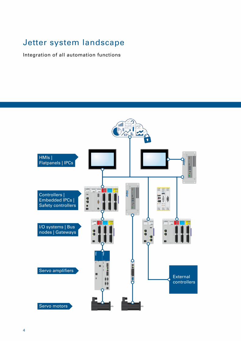
Jetter system landscapeIntegration of all automation functions
External controllers
HMIs | Flatpanels | IPCs
Controllers | Embedded IPCs |Safety controllers
I/O systems | Bus nodes | Gateways
Servo ampli�ers
Servo motors
5
For decades, the name Jetter AG has stood
for the highest standards of automation
solutions that are used in a wide range of
industrial and mobile automation sectors.
Products and components by Jetter AG
stand out thanks to their high degree of
system integrity and diversity. Our in-house
R&D departments (hardware and software),
as well as our production plants in Germany
allow us to always act in a quick and flexible
manner. This, combined with a comprehen-
sive range of Professional Services, enables
us to put almost any customer request into
practice.
In Industrial Automation Jetter AG is fo-
cusing on selected industries. Highly cus-
tomized solutions contributing to decisive
advantages in our customers' business en-
vironment put them into a position to pro-
duce state-of-the-art machines and plants.
In Mobile Automation Jetter AG develops
and manufactures highly complex and ro-
bust automation concepts for controlling a
wide variety of functions in municipal, fire-
fighting, and agricultural vehicles. Thus,
permanent availability of vehicles and im-
plements is ensured.
The Jetter AG mission statement:
Jetter AG is a leading provider of automation systems. Under-
standing your application helps us find the perfect solution in
terms of functionality, sustainability and efficiency.
Industrial AutomationExperience | Know-how | Made in Germany
Radical changes in industry caused by In-
dustry 4.0 and Internet of Things demand
for future-proof solutions. Jetter AG is able
to provide you with well-proven and safe
systems, and to actively support you in im-
plementing all process steps.
The product and networking philosophy at
Jetter AG has always been based on seam-
less integration of all automation compo-
nents into the production processes. Jetter
AG was the first company in the world to
rely on consistent networking with Ether-
net TCP/IP and on using common Internet
protocols. A great number of systems that
already now meet all essential criteria of fu-
ture demands on production processes has
been applied for many years by renowned
customers with great success.
6
Software solutions
7
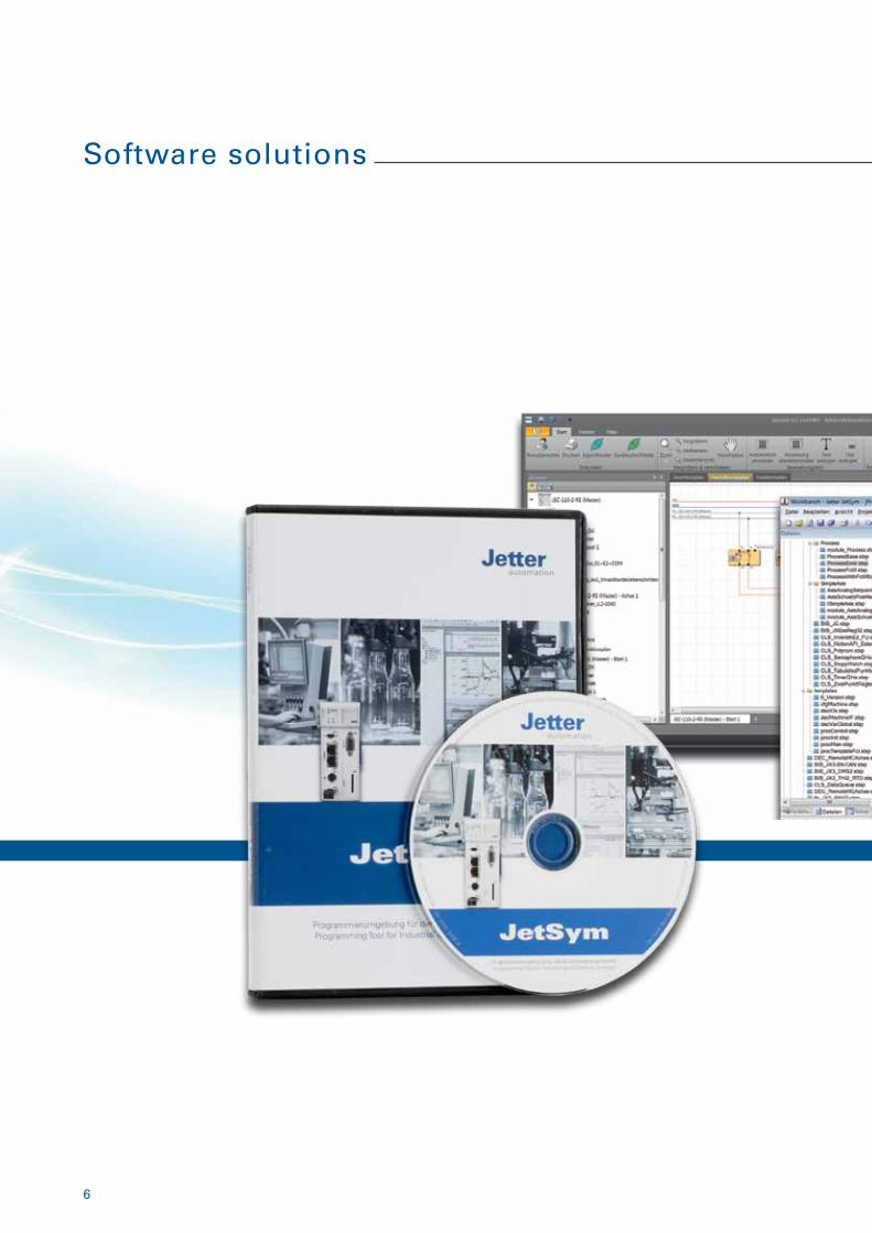
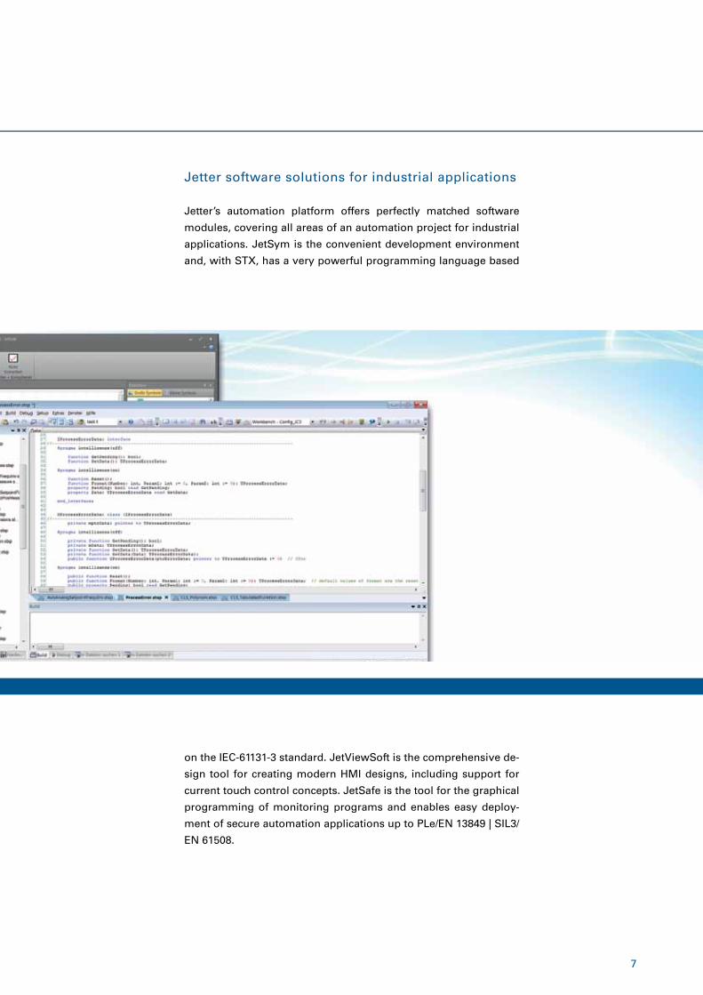
Jetter software solutions for industrial applications
Jetter’s automation platform offers perfectly matched software
modules, covering all areas of an automation project for industrial
applications. JetSym is the convenient development environment
and, with STX, has a very powerful programming language based
on the IEC-61131-3 standard. JetViewSoft is the comprehensive de-
sign tool for creating modern HMI designs, including support for
current touch control concepts. JetSafe is the tool for the graphical
programming of monitoring programs and enables easy deploy-
ment of secure automation applications up to PLe/EN 13849 | SIL3/
EN 61508.
8
Automation platform
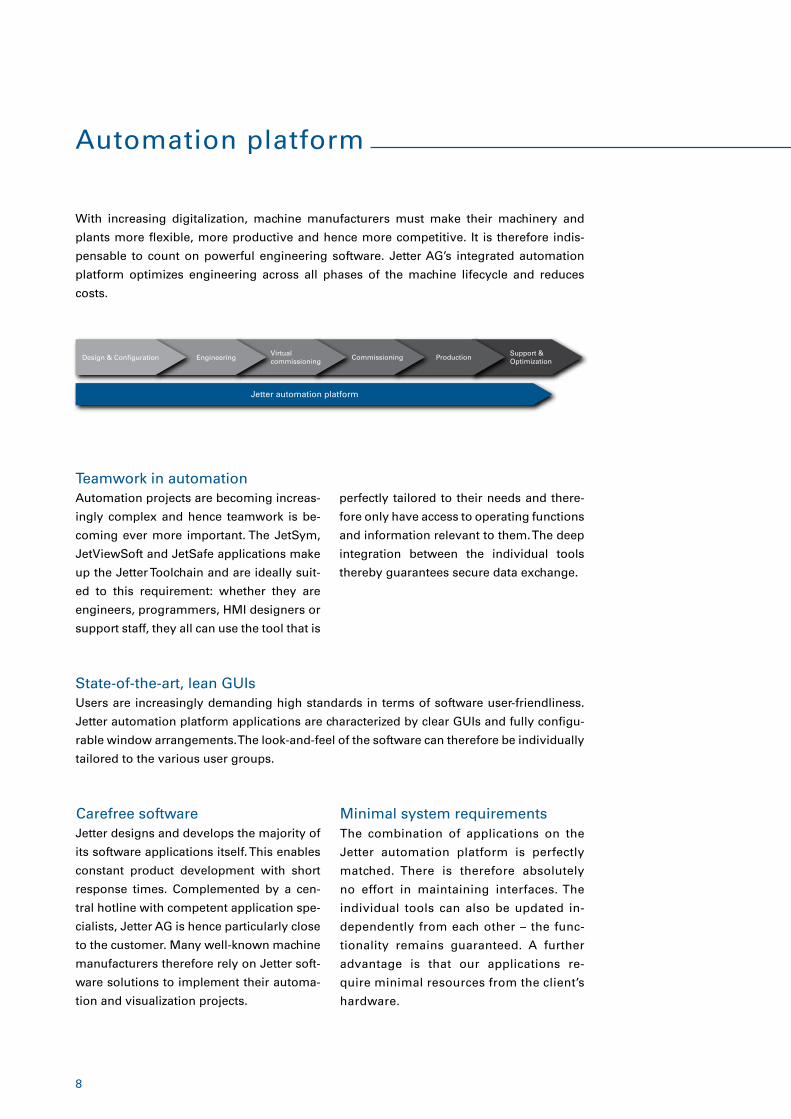
With increasing digitalization, machine manufacturers must make their machinery and
plants more flexible, more productive and hence more competitive. It is therefore indis-
pensable to count on powerful engineering software. Jetter AG’s integrated automation
platform optimizes engineering across all phases of the machine lifecycle and reduces
costs.
Automation projects are becoming increas-
ingly complex and hence teamwork is be-
coming ever more important. The JetSym,
JetViewSoft and JetSafe applications make
up the Jetter Toolchain and are ideally suit-
ed to this requirement: whether they are
engineers, programmers, HMI designers or
support staff, they all can use the tool that is
Users are increasingly demanding high standards in terms of software user-friendliness.
Jetter automation platform applications are characterized by clear GUIs and fully configu-
rable window arrangements. The look-and-feel of the software can therefore be individually
tailored to the various user groups.
The combination of applications on the
Jetter automation platform is perfectly
matched. There is therefore absolutely
no effort in maintaining interfaces. The
individual tools can also be updated in-
dependently from each other – the func-
tionality remains guaranteed. A further
advantage is that our applications re-
quire minimal resources from the client’s
hardware.
Jetter designs and develops the majority of
its software applications itself. This enables
constant product development with short
response times. Complemented by a cen-
tral hotline with competent application spe-
cialists, Jetter AG is hence particularly close
to the customer. Many well-known machine
manufacturers therefore rely on Jetter soft-
ware solutions to implement their automa-
tion and visualization projects.
Teamwork in automation
State-of-the-art, lean GUIs
Minimal system requirementsCarefree software
Design & Con�guration Engineering Commissioning ProductionVirtual commissioning
Support &Optimization
Jetter automation platform
perfectly tailored to their needs and there-
fore only have access to operating functions
and information relevant to them. The deep
integration between the individual tools
thereby guarantees secure data exchange.
9
JetSym – the programming environment
JetSym is Jetter AG’s central programming environment and offers, in addition to writing
pure program code, extensive support in the areas of configuration, debugging, diagnos-
tics and commissioning a machine.
JetSym enables any number of config-
urations of the same project to be cre-
ated. Project configurations differ in the
hardware used and their configuration.
In this way, different machine versions
can be created and tested, particularly
during the commissioning phase of a
machine.
Flexible project configurationJetSym already provides seamless inte-
gration with popular version management
tools, such as Apache Subversion (SVN),
which allows entire automation projects
or their individual components to be ver-
sioned independently. The user is informed
visually of the current object status in the
project overview.
Version management – tool connection
Powerful debuggerJetSym’s extensive debugging capabilities
enhance inline monitoring of STX projects,
making troubleshooting and commission-
ing easier. The program sequence can be in-
terrupted by setting absolute or conditional
breakpoints, and further program execution
can be tracked in individual steps. At the
same time, the setup window helps you to
view and monitor selected symbol values
during debugging.
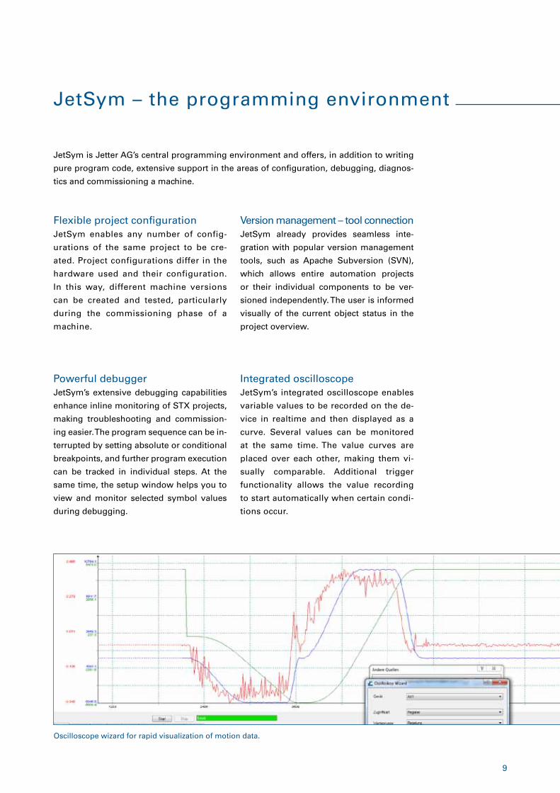
Integrated oscilloscopeJetSym’s integrated oscilloscope enables
variable values to be recorded on the de-
vice in realtime and then displayed as a
curve. Several values can be monitored
at the same time. The value curves are
placed over each other, making them vi-
sually comparable. Additional trigger
functionality allows the value recording
to start automatically when certain condi-
tions occur.
Oscilloscope wizard for rapid visualization of motion data.
10
MultitaskingFor Jetter controllers, multitasking takes
place at the language level, not within the
operating system. This ensures that the time
response of the tasks is identical on differ-
ent controller types. In addition, debugging
is simplified by allowing individual tasks to
be stopped or started separately thanks to
multitasking.
Support for secure codingJetSym greatly helps programmers in their everyday work. The in-
tegrated IntelliSense proposes meaningful attributes and methods
while you type. Together with AutoComplete, programming speed
and accuracy therefore increase. Navigating the code is also simpli-
fied by highlighting syntax and marking matching keywords.
Template managementAutomation projects can be saved in JetSym as a new template at
any time and are therefore then available as a template for future
automation projects. The template includes not only the program
code itself, but also the complete hardware settings and axis con-
figurations, etc. This increases the reusability of projects and proj-
ect components .
Plug-and-play – extpansion modulesUsing Jetter AG’s perfectly matched hard-
ware and software components, automa-
tion projects can be set up very quickly and
easily. JetSym recognizes newly connected
modules immediately, and the basic con-
figuration such as input/output addressing
is handled automatically.
� Clear depiction of all files that are relevant to the project
� Flexible project configuration
� Connection to version management tools
� Powerful debugger
� Extensive tracing and monitoring
� Integrated oscilloscope
� Integrated multitasking
� Support for secure coding
� Simulator and soft PLC for commissioning without hardware
� Connection to Siemens SIMIT for virtual commissioning
� Support of all major fieldbus systems such as EtherCAT®
� Plug and play with expansion modules
Overview of highlights
JetSym – the programming environment
In addition to debugging, JetSym’s tracing and monitoring function offers further assistance in programming and
commissioning automation projects. The Trace function allows values or individual messages to be output without
interrupting the program. Specific conditions can also be defined where the output of a trace message should ap-
pear. Further support is provided by JetSym’s built-in monitoring function, which allows function parameters and
variable values to be displayed at runtime simply by moving the cursor to the code location to be monitored.
Tracing and Monitoring
11
STX is a language the syntax of which is based on IEC 61131-3 ST. Due to numerous en-
hancements, it meets all the requirements of modern programming in the automation en-
vironment. STX is characterized by two key features in program creation:
� The process-oriented approach makes direct mapping of real plant processes possible
� The object-oriented approach greatly reduces development and testing time
The majority of programmable logic controllers on the market are cycle oriented. Accord-
ingly, such a control program queries all values again for each program cycle, while STX
only once queries the values necessary for the current program step. This results in some
crucial differences:
Process-oriented coding
STX – the programming language
Loop coding Process-oriented coding
Individual processes are split into steps and implemented as state machines (se-quences).
The programs are process-oriented, i.e. they run in chronological order.
The order of execution is defined by state changes and not by the order in the program as in traditional programming languages.
The structuring of the tasks is based much more on the actual running processes within the plant/machine.
Extensive functions and loops must be split into tasks to ensure cycle time compli-ance.
STX’s When command allows the program to wait for feedback from various events within a task.
The structuring of the different tasks often has little to do with the actual processes within the plant/machine.
Extensive functions and loops can be implemented exactly where they are required.
Loop coding requires specially trained PLC programmers. In contrast, process-oriented
coding can be learned very easily and quickly by mechanical engineers. There is another
advantage: The structure of the programs is based much more on the program structure of
modern high-level languages.
12
Based on modern high-level languagesThe structured programming language Structured Text, which is
standardized in IEC-61131-3, forms the basis for STX, but the scope
of the language has been significantly expanded. For example, ob-
jects and their properties can be conveniently addressed via dot
notation. This improves the readability of the program code. STX
also offers powerful commands for arithmetic, axis handling and
user guidance. Integrated functions for character string processing
and file operations further simplify controller programming.
STX – the programming language
Object orientationAutomation programs are becoming increasingly powerful as part
of Industrie 4.0, yet also more complex. With its consistent object-
oriented programming approach, the programming language STX
enables the development of modular programs, making the pro-
gram code much more flexible with respect to customizations and
expansions. Due to clearly defined interfaces between the code
blocks, individual blocks can be modified or replaced at any time
without risking undesirable side effects. This can significantly re-
duce development time and testing time.
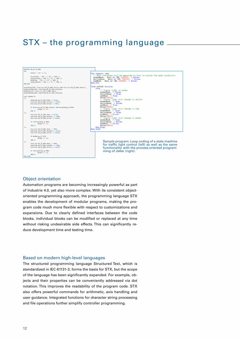
Sample program: Loop coding of a state machine for traffic light control (left) as well as the same functionality with the process-oriented program-ming of Jetter (right).
13
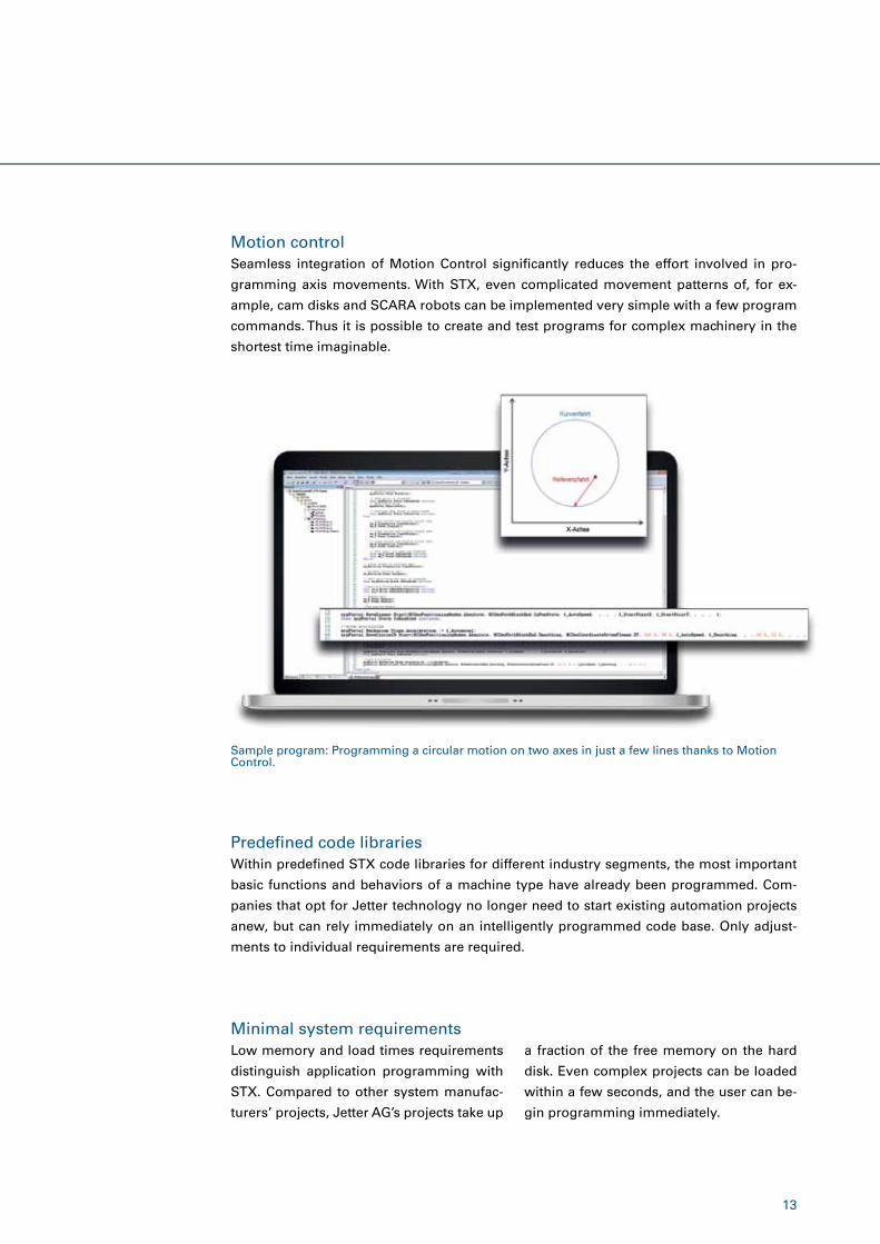
Motion controlSeamless integration of Motion Control significantly reduces the effort involved in pro-
gramming axis movements. With STX, even complicated movement patterns of, for ex-
ample, cam disks and SCARA robots can be implemented very simple with a few program
commands. Thus it is possible to create and test programs for complex machinery in the
shortest time imaginable.
Predefined code librariesWithin predefined STX code libraries for different industry segments, the most important
basic functions and behaviors of a machine type have already been programmed. Com-
panies that opt for Jetter technology no longer need to start existing automation projects
anew, but can rely immediately on an intelligently programmed code base. Only adjust-
ments to individual requirements are required.
Minimal system requirementsLow memory and load times requirements
distinguish application programming with
STX. Compared to other system manufac-
turers’ projects, Jetter AG’s projects take up
Sample program: Programming a circular motion on two axes in just a few lines thanks to Motion Control.
a fraction of the free memory on the hard
disk. Even complex projects can be loaded
within a few seconds, and the user can be-
gin programming immediately.
14
JetViewSoft – the design tool
JetViewSoft is the design tool for state-of-
the-art, professional HMI process visual-
ization. The editor stands out for its high
performance and functionality, while re-
maining very user friendly. Together with
JetViewSoft’s object-oriented approach,
even extensive visualization projects can be
implemented simply and efficiently.
The object-oriented approach of JetViewSoft makes generating
screens a lot easier. Objects such as buttons need to be defined
only once before they can be used as often as they are needed.
Making changes to an object property automatically takes effect
wherever this object has been applied. Various visualization objects
can dynamically be displayed or exchanged during runtime in the
control program by means of pointers.
Object-oriented and efficient
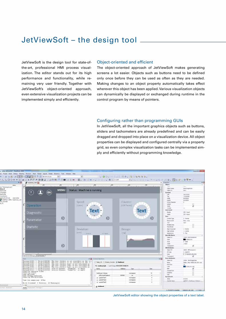
In JetViewSoft, all the important graphics objects such as buttons,
sliders and tachometers are already predefined and can be easily
dragged and dropped into place on a visualization device. All object
properties can be displayed and configured centrally via a property
grid, so even complex visualization tasks can be implemented sim-
ply and efficiently without programming knowledge.
Configuring rather than programming GUIs
JetViewSoft editor showing the object properties of a text label.
15
Vector graphics platformThe vector graphics technology of JetViewSoft allows for complete
and lossless scalability of all objects (except for bitmap graphics).
Projects or project parts that have been designed for a specific tar-
get resolution can therefore be displayed at a different resolution
without loss of quality.
Built-in macro languageFor simple processes, JetViewSoft offers configurable macro func-
tions. More complex processes, calculations or programming of
special functions can also be carried out with the integrated STX
interpreter. The corresponding program code is implemented using
STX in JetSym.
SVG importJetViewSoft supports the graphics format SVG. Cumbersome con-
version of CAD drawings into bitmap format is therefore a thing
of the past. In addition, the foreground and background colors of
SVG objects can be overridden directly within JetViewSoft. Differ-
ent colors, for example of warning or error symbols, can thus be
assigned directly. This greatly minimizes the graphic department’s
costs since corresponding icons only need to be provided and im-
ported in a single color variant.
Simple internationalizationJetViewSoft allows multiple languages to be integrated, maintained
and also translated very easily and conveniently. For this purpose,
the language tags of the different languages can be managed on a
clear user interface. Language tags lists can be exported and reim-
ported in CSV format to facilitate working with translation agencies.
Dynamic IOsUsing dynamic IOs, graphics objects of the HMI can be updated at
runtime without even writing a single line of program code. The
corresponding values are continuously polled from the controller
and the visualization updated accordingly.
16
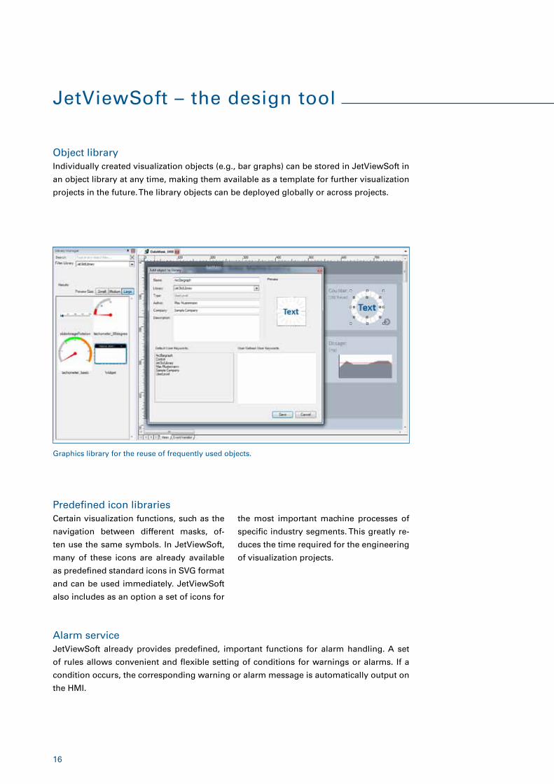
Object libraryIndividually created visualization objects (e.g., bar graphs) can be stored in JetViewSoft in
an object library at any time, making them available as a template for further visualization
projects in the future. The library objects can be deployed globally or across projects.
Predefined icon librariesCertain visualization functions, such as the
navigation between different masks, of-
ten use the same symbols. In JetViewSoft,
many of these icons are already available
as predefined standard icons in SVG format
and can be used immediately. JetViewSoft
also includes as an option a set of icons for
JetViewSoft – the design tool
Graphics library for the reuse of frequently used objects.
Alarm serviceJetViewSoft already provides predefined, important functions for alarm handling. A set
of rules allows convenient and flexible setting of conditions for warnings or alarms. If a
condition occurs, the corresponding warning or alarm message is automatically output on
the HMI.
the most important machine processes of
specific industry segments. This greatly re-
duces the time required for the engineering
of visualization projects.
17
Integrated rights managementIntegrated rights management enables secure access to certain control functions. To do
this, JetViewSoft provides a user interface where different users, passwords and authoriza-
tion levels can be managed. Each interaction object within the visualization may be indi-
vidually assigned to a particular authorization level in order, for example, to make the basic
configuration of a machine accessible only to certain groups of people.
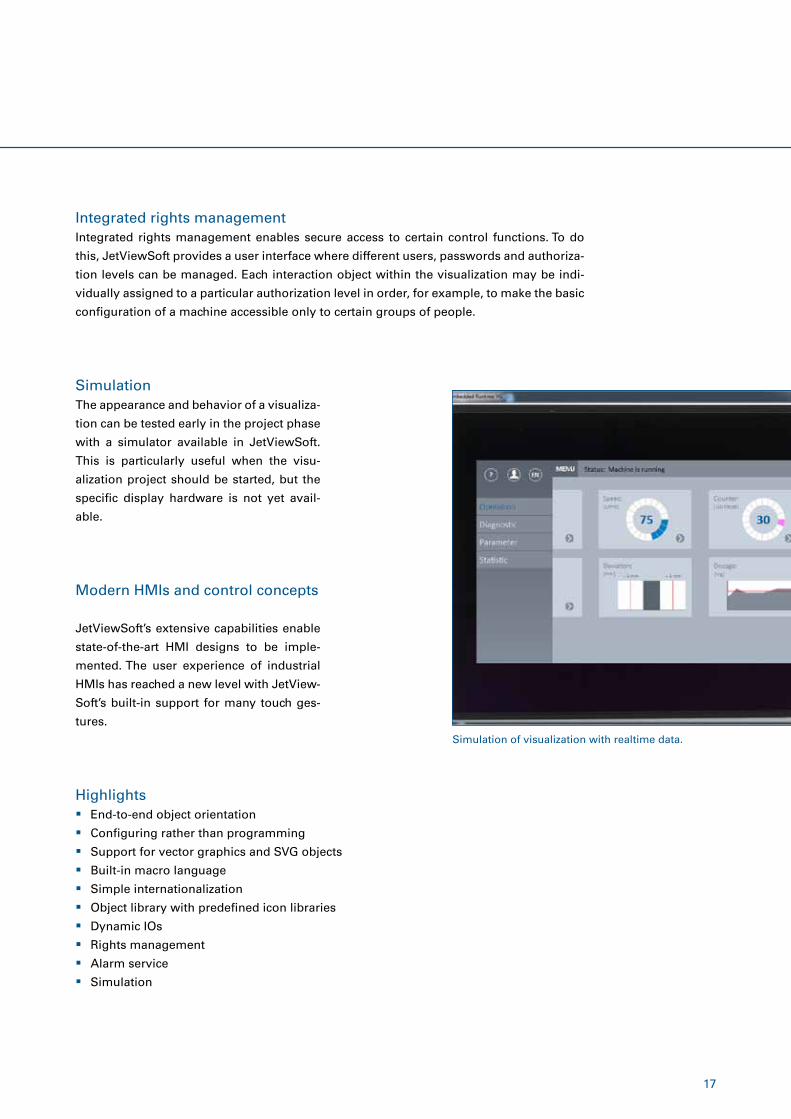
SimulationThe appearance and behavior of a visualiza-
tion can be tested early in the project phase
with a simulator available in JetViewSoft.
This is particularly useful when the visu-
alization project should be started, but the
specific display hardware is not yet avail-
able.
Modern HMIs and control concepts
JetViewSoft’s extensive capabilities enable
state-of-the-art HMI designs to be imple-
mented. The user experience of industrial
HMIs has reached a new level with JetView-
Soft’s built-in support for many touch ges-
tures.
� End-to-end object orientation
� Configuring rather than programming
� Support for vector graphics and SVG objects
� Built-in macro language
� Simple internationalization
� Object library with predefined icon libraries
� Dynamic IOs
� Rights management
� Alarm service
� Simulation
Highlights
Simulation of visualization with realtime data.
18
JetSafe – programming safely
JetSafe is the tool of choice when it comes
to creating safety-compliant control pro-
grams for the PLe/EN 13849 | SIL3/EN 61508
levels. JetSafe is perfectly matched to Jetter
safety controllers.
Module management and device assignmentJetSafe’s clear user interface makes it par-
ticularly easy to assign the individual mod-
ules (IOs and axis monitors) to the sensors
and functions of the machine, taking into
account the required performance level.
Monitoring functionsA comprehensive range of motion monitor-
ing functions is available, such as monitor-
ing of speed, standstill, range, and direction.
These functions can directly be parameter-
ized in a context-oriented way.
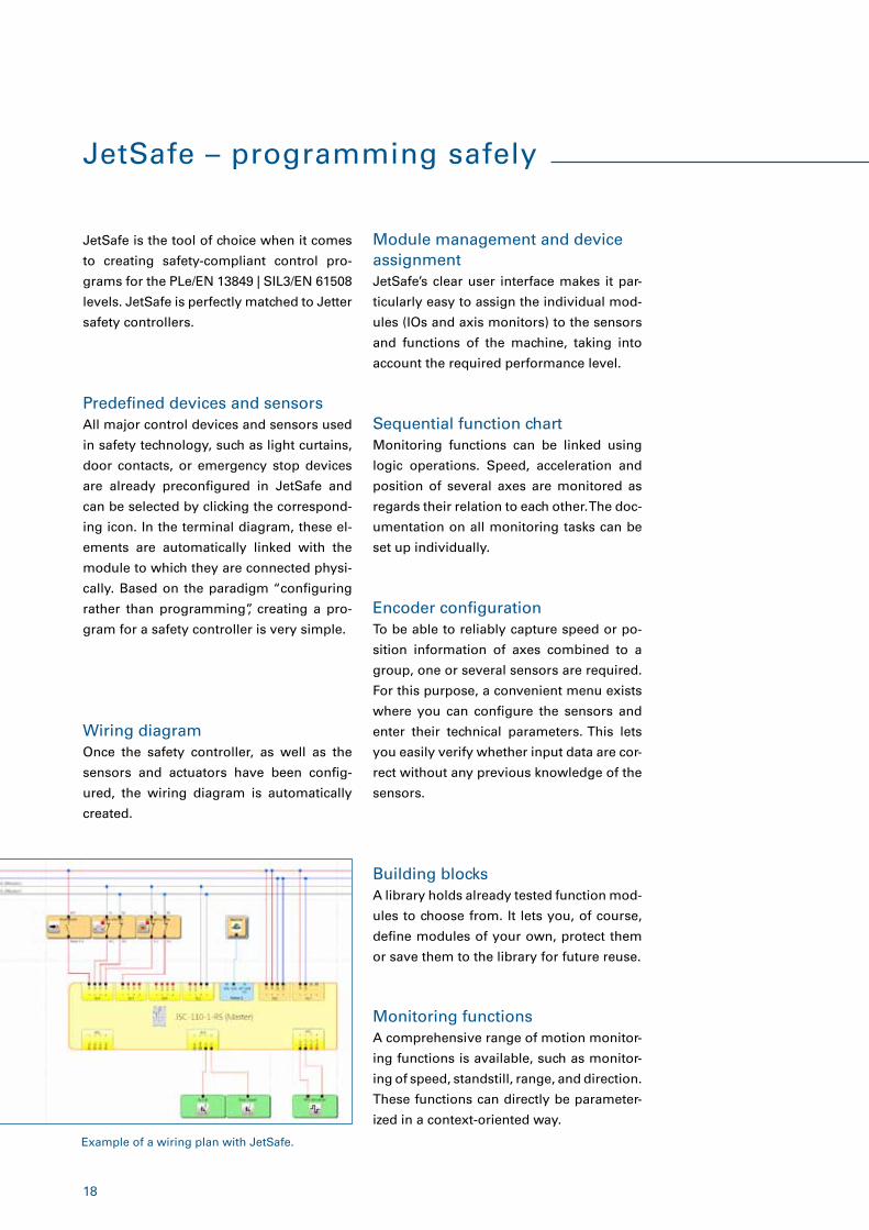
Wiring diagramOnce the safety controller, as well as the
sensors and actuators have been config-
ured, the wiring diagram is automatically
created.
Predefined devices and sensorsAll major control devices and sensors used
in safety technology, such as light curtains,
door contacts, or emergency stop devices
are already preconfigured in JetSafe and
can be selected by clicking the correspond-
ing icon. In the terminal diagram, these el-
ements are automatically linked with the
module to which they are connected physi-
cally. Based on the paradigm “configuring
rather than programming”, creating a pro-
gram for a safety controller is very simple.
Encoder configurationTo be able to reliably capture speed or po-
sition information of axes combined to a
group, one or several sensors are required.
For this purpose, a convenient menu exists
where you can configure the sensors and
enter their technical parameters. This lets
you easily verify whether input data are cor-
rect without any previous knowledge of the
sensors.
Sequential function chartMonitoring functions can be linked using
logic operations. Speed, acceleration and
position of several axes are monitored as
regards their relation to each other. The doc-
umentation on all monitoring tasks can be
set up individually.
Building blocksA library holds already tested function mod-
ules to choose from. It lets you, of course,
define modules of your own, protect them
or save them to the library for future reuse.
Example of a wiring plan with JetSafe.
19
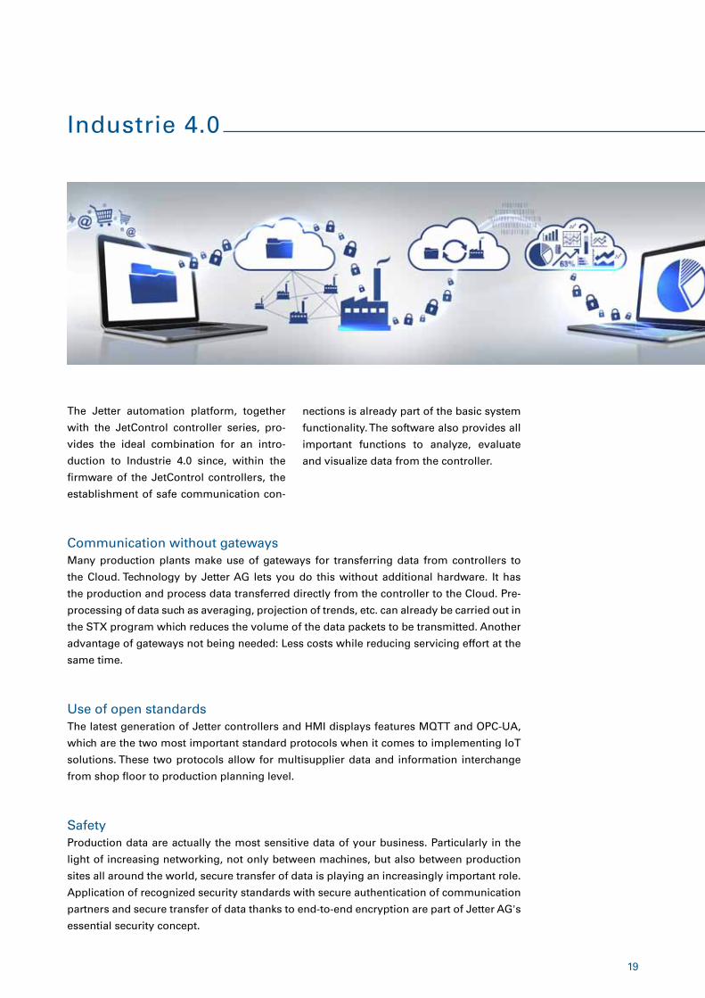
Industrie 4.0
Communication without gatewaysMany production plants make use of gateways for transferring data from controllers to
the Cloud. Technology by Jetter AG lets you do this without additional hardware. It has
the production and process data transferred directly from the controller to the Cloud. Pre-
processing of data such as averaging, projection of trends, etc. can already be carried out in
the STX program which reduces the volume of the data packets to be transmitted. Another
advantage of gateways not being needed: Less costs while reducing servicing effort at the
same time.
The Jetter automation platform, together
with the JetControl controller series, pro-
vides the ideal combination for an intro-
duction to Industrie 4.0 since, within the
firmware of the JetControl controllers, the
establishment of safe communication con-
Use of open standardsThe latest generation of Jetter controllers and HMI displays features MQTT and OPC-UA,
which are the two most important standard protocols when it comes to implementing IoT
solutions. These two protocols allow for multisupplier data and information interchange
from shop floor to production planning level.
SafetyProduction data are actually the most sensitive data of your business. Particularly in the
light of increasing networking, not only between machines, but also between production
sites all around the world, secure transfer of data is playing an increasingly important role.
Application of recognized security standards with secure authentication of communication
partners and secure transfer of data thanks to end-to-end encryption are part of Jetter AG's
essential security concept.
nections is already part of the basic system
functionality. The software also provides all
important functions to analyze, evaluate
and visualize data from the controller.
20
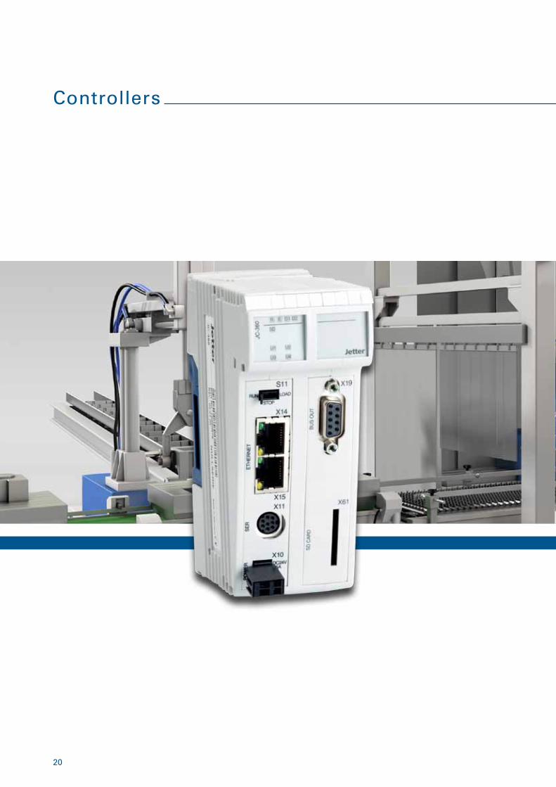
Controllers
21
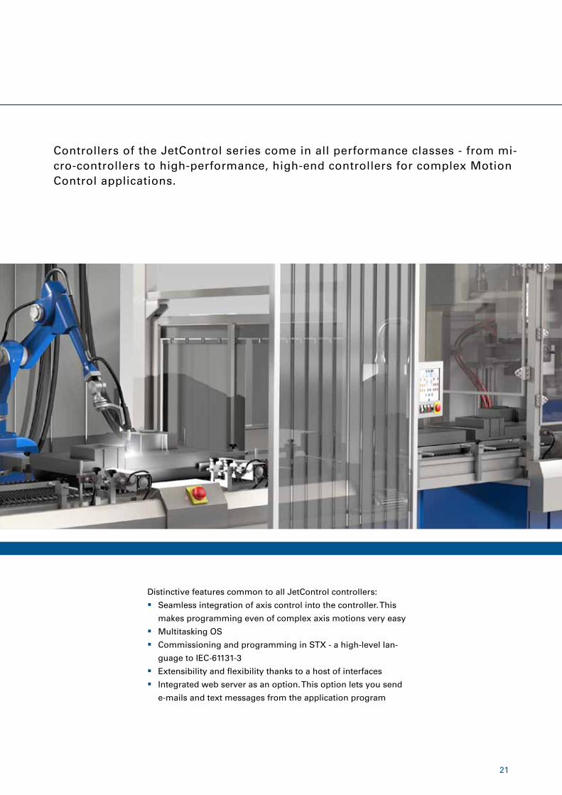
Distinctive features common to all JetControl controllers:
� Seamless integration of axis control into the controller. This
makes programming even of complex axis motions very easy
� Multitasking OS
� Commissioning and programming in STX - a high-level lan-
guage to IEC-61131-3
� Extensibility and flexibility thanks to a host of interfaces
� Integrated web server as an option. This option lets you send
e-mails and text messages from the application program
Controllers of the JetControl series come in all performance classes - from mi-cro-controllers to high-performance, high-end controllers for complex Motion Control applications.
22
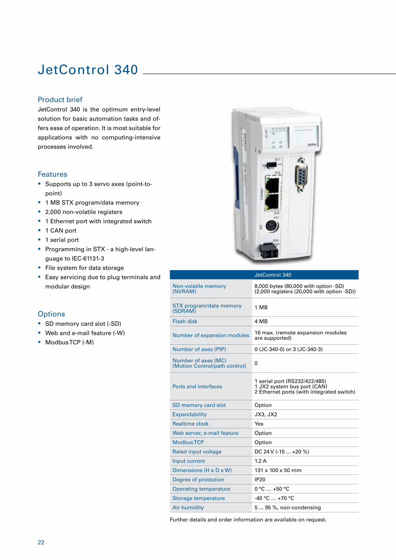
JetControl 340
Product brief
Features
Options
JetControl 340 is the optimum entry-level
solution for basic automation tasks and of-
fers ease of operation. It is most suitable for
applications with no computing-intensive
processes involved.
� Supports up to 3 servo axes (point-to-
point)
� 1 MB STX program/data memory
� 2,000 non-volatile registers
� 1 Ethernet port with integrated switch
� 1 CAN port
� 1 serial port
� Programming in STX - a high-level lan-
guage to IEC-61131-3
� File system for data storage
� Easy servicing due to plug terminals and
modular design
� SD memory card slot (-SD)
� Web and e-mail feature (-W)
� Modbus TCP (-M)
JetControl 340
Non-volatile memory (NVRAM)
8,000 bytes (80,000 with option -SD)(2,000 registers (20,000 with option -SD))
STX program/data memory (SDRAM)
1 MB
Flash disk 4 MB
Number of expansion modules 16 max. (remote expansion modules are supported)
Number of axes (PtP) 0 (JC-340-0) or 3 (JC-340-3)
Number of axes (MC) (Motion Control/path control) 0
Ports and interfaces1 serial port (RS232/422/485) 1 JX2 system bus port (CAN) 2 Ethernet ports (with integrated switch)
SD memory card slot Option
Expandability JX3, JX2
Realtime clock Yes
Web server, e-mail feature Option
Modbus TCP Option
Rated input voltage DC 24 V (-15 ... +20 %)
Input current 1.2 A
Dimensions (H x D x W) 131 x 100 x 50 mm
Degree of protection IP20
Operating temperature 0 °C … +50 °C
Storage temperature -40 °C … +70 °C
Air humidity 5 ... 95 %, non-condensing
Further details and order information are available on request.
23
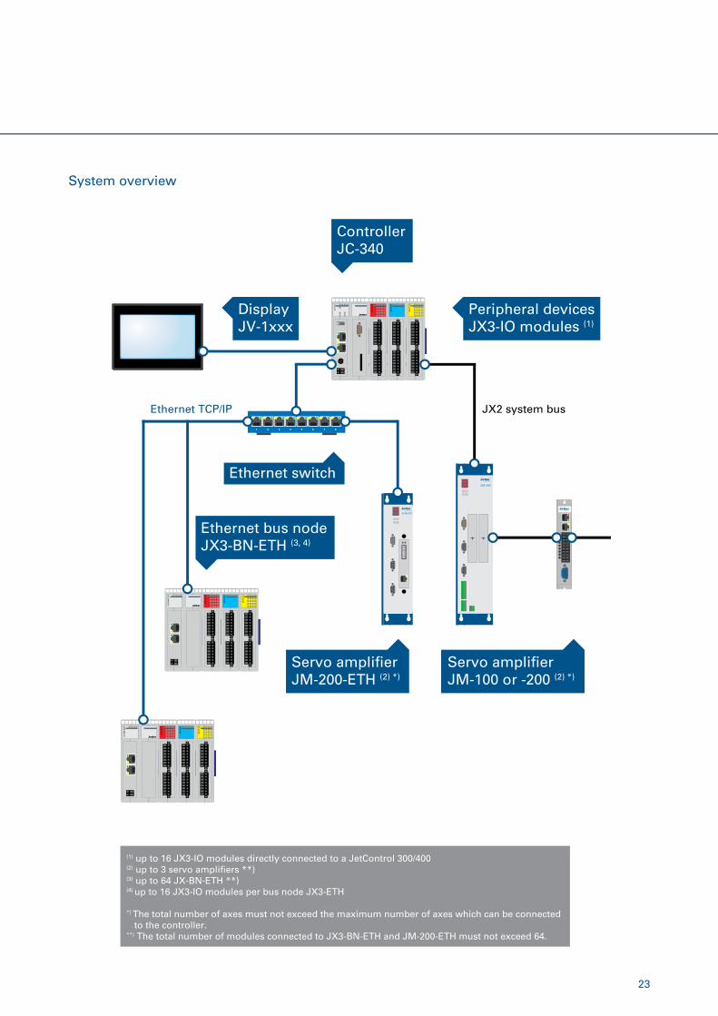
System overview
Servo ampli�erJM-200-ETH (2) *)
(1) up to 16 JX3-IO modules directly connected to a JetControl 300/400(2) up to 3 servo ampli�ers **)(3) up to 64 JX-BN-ETH **)(4) up to 16 JX3-IO modules per bus node JX3-ETH
*) The total number of axes must not exceed the maximum number of axes which can be connected to the controller.**) The total number of modules connected to JX3-BN-ETH and JM-200-ETH must not exceed 64.
Servo ampli�erJM-100 or -200 (2) *)
Ethernet bus nodeJX3-BN-ETH (3, 4)
DisplayJV-1xxx
Peripheral devicesJX3-IO modules (1)
ControllerJC-340
JX2 system bus
Ethernet switch
1 2 3 4 5 6 7 8
Ethernet TCP/IP
24
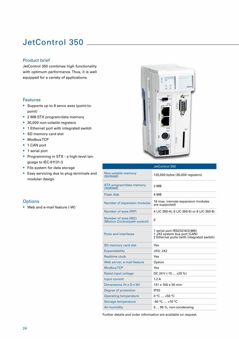
JetControl 350
Product brief
Features
Options
JetControl 350 combines high functionality
with optimum performance. Thus, it is well
equipped for a variety of applications.
� Supports up to 8 servo axes (point-to-
point)
� 2 MB STX program/data memory
� 30,000 non-volatile registers
� 1 Ethernet port with integrated switch
� SD memory card slot
� Modbus TCP
� 1 CAN port
� 1 serial port
� Programming in STX - a high-level lan-
guage to IEC-61131-3
� File system for data storage
� Easy servicing due to plug terminals and
modular design
� Web and e-mail feature (-W)
JetControl 350
Non-volatile memory (NVRAM) 120,000 bytes (30,000 registers)
STX program/data memory (SDRAM)
2 MB
Flash disk 4 MB
Number of expansion modules 16 max. (remote expansion modules are supported)
Number of axes (PtP) 4 (JC-350-4), 6 (JC-350-6) or 8 (JC-350-8)
Number of axes (MC) (Motion Control/path control) 0
Ports and interfaces1 serial port (RS232/422/485) 1 JX2 system bus port (CAN) 2 Ethernet ports (with integrated switch)
SD memory card slot Yes
Expandability JX3, JX2
Realtime clock Yes
Web server, e-mail feature Option
Modbus TCP Yes
Rated input voltage DC 24 V (-15 ... +20 %)
Input current 1.2 A
Dimensions (H x D x W) 131 x 100 x 50 mm
Degree of protection IP20
Operating temperature 0 °C … +50 °C
Storage temperature -40 °C … +70 °C
Air humidity 5 ... 95 %, non-condensing
Further details and order information are available on request.
25
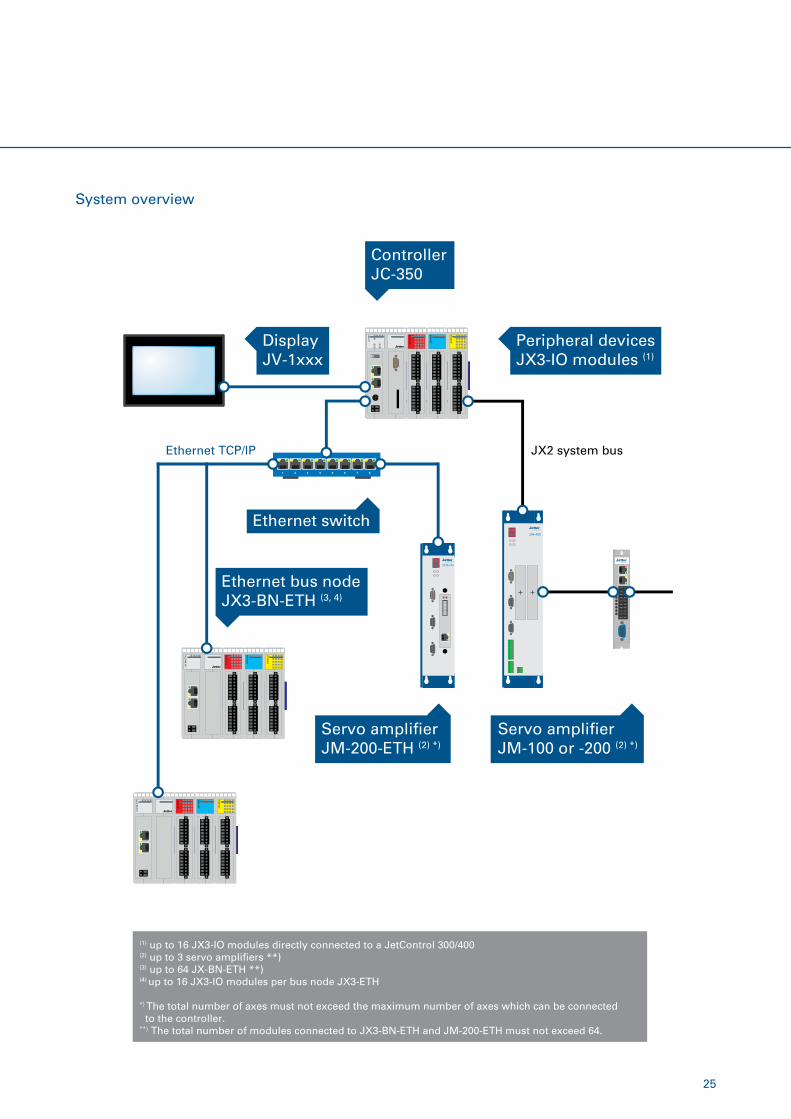
System overview
Servo ampli�erJM-200-ETH (2) *)
(1) up to 16 JX3-IO modules directly connected to a JetControl 300/400(2) up to 3 servo ampli�ers **)(3) up to 64 JX-BN-ETH **)(4) up to 16 JX3-IO modules per bus node JX3-ETH
*) The total number of axes must not exceed the maximum number of axes which can be connected to the controller.**) The total number of modules connected to JX3-BN-ETH and JM-200-ETH must not exceed 64.
Ethernet bus nodeJX3-BN-ETH (3, 4)
DisplayJV-1xxx
Peripheral devicesJX3-IO modules (1)
ControllerJC-350
JX2 system bus
Ethernet switch
1 2 3 4 5 6 7 8
Ethernet TCP/IP
Servo ampli�erJM-100 or -200 (2) *)
26
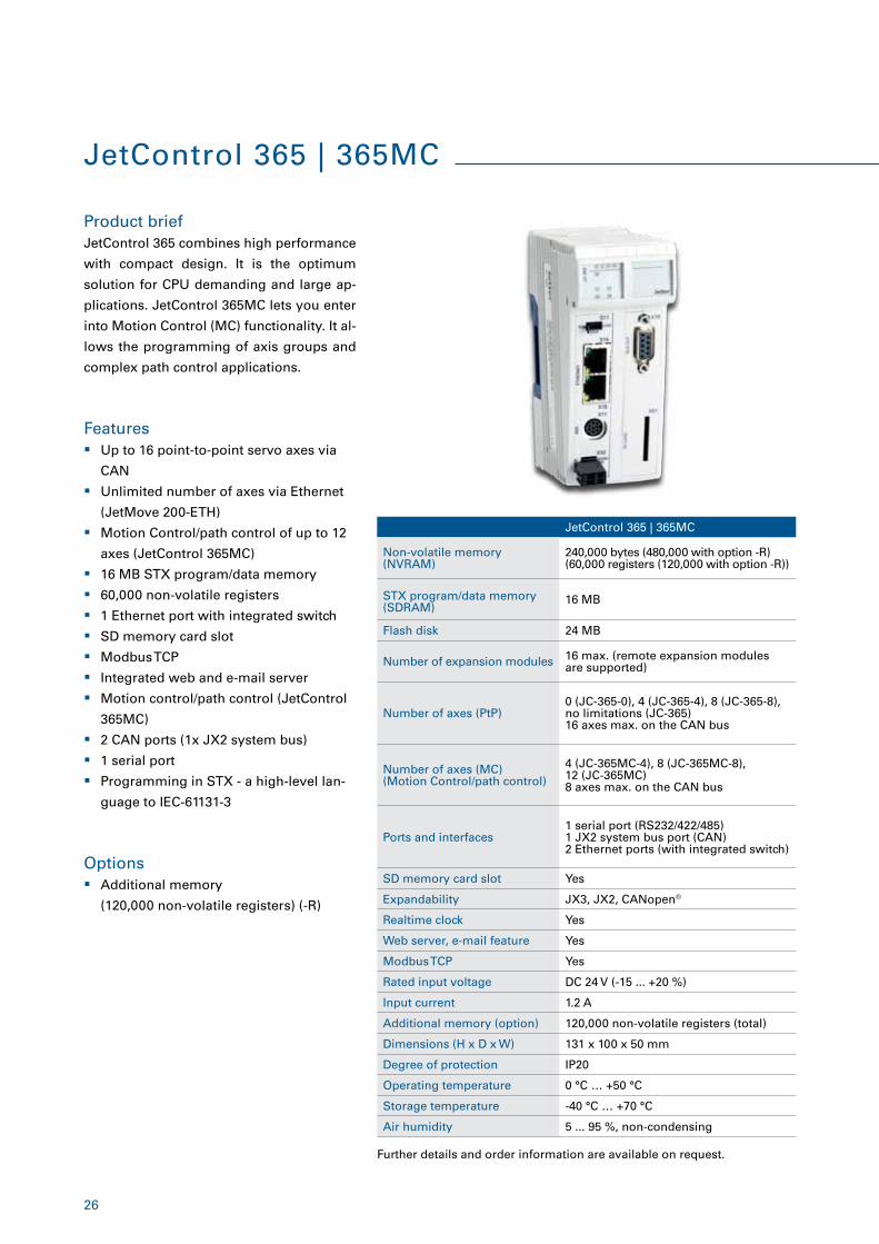
JetControl 365 | 365MC
Product brief
Features
JetControl 365 combines high performance
with compact design. It is the optimum
solution for CPU demanding and large ap-
plications. JetControl 365MC lets you enter
into Motion Control (MC) functionality. It al-
lows the programming of axis groups and
complex path control applications.
� Up to 16 point-to-point servo axes via
CAN
� Unlimited number of axes via Ethernet
(JetMove 200-ETH)
� Motion Control/path control of up to 12
axes (JetControl 365MC)
� 16 MB STX program/data memory
� 60,000 non-volatile registers
� 1 Ethernet port with integrated switch
� SD memory card slot
� Modbus TCP
� Integrated web and e-mail server
� Motion control/path control (JetControl
365MC)
� 2 CAN ports (1x JX2 system bus)
� 1 serial port
� Programming in STX - a high-level lan-
guage to IEC-61131-3
JetControl 365 | 365MC
Non-volatile memory (NVRAM)
240,000 bytes (480,000 with option -R)(60,000 registers (120,000 with option -R))
STX program/data memory (SDRAM)
16 MB
Flash disk 24 MB
Number of expansion modules 16 max. (remote expansion modules are supported)
Number of axes (PtP)0 (JC-365-0), 4 (JC-365-4), 8 (JC-365-8), no limitations (JC-365) 16 axes max. on the CAN bus
Number of axes (MC) (Motion Control/path control)
4 (JC-365MC-4), 8 (JC-365MC-8), 12 (JC-365MC) 8 axes max. on the CAN bus
Ports and interfaces1 serial port (RS232/422/485) 1 JX2 system bus port (CAN) 2 Ethernet ports (with integrated switch)
SD memory card slot Yes
Expandability JX3, JX2, CANopen®
Realtime clock Yes
Web server, e-mail feature Yes
Modbus TCP Yes
Rated input voltage DC 24 V (-15 ... +20 %)
Input current 1.2 A
Additional memory (option) 120,000 non-volatile registers (total)
Dimensions (H x D x W) 131 x 100 x 50 mm
Degree of protection IP20
Operating temperature 0 °C … +50 °C
Storage temperature -40 °C … +70 °C
Air humidity 5 ... 95 %, non-condensing
Options � Additional memory
(120,000 non-volatile registers) (-R)
Further details and order information are available on request.
27
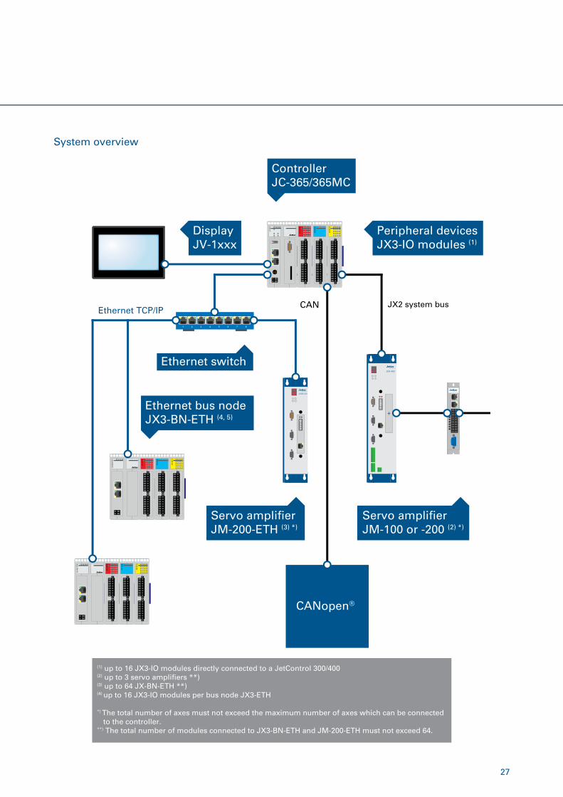
System overview
DisplayJV-1xxx
JX2 system bus
CANopen®
CAN
Peripheral devicesJX3-IO modules (1)
ControllerJC-365/365MC
Servo ampli�erJM-100 or -200 (2) *)
Servo ampli�erJM-200-ETH (3) *)
Ethernet bus nodeJX3-BN-ETH (4, 5)
Ethernet switch
1 2 3 4 5 6 7 8
Ethernet TCP/IP
(1) up to 16 JX3-IO modules directly connected to a JetControl 300/400(2) up to 3 servo ampli�ers **)(3) up to 64 JX-BN-ETH **)(4) up to 16 JX3-IO modules per bus node JX3-ETH
*) The total number of axes must not exceed the maximum number of axes which can be connected to the controller.**) The total number of modules connected to JX3-BN-ETH and JM-200-ETH must not exceed 64.
28
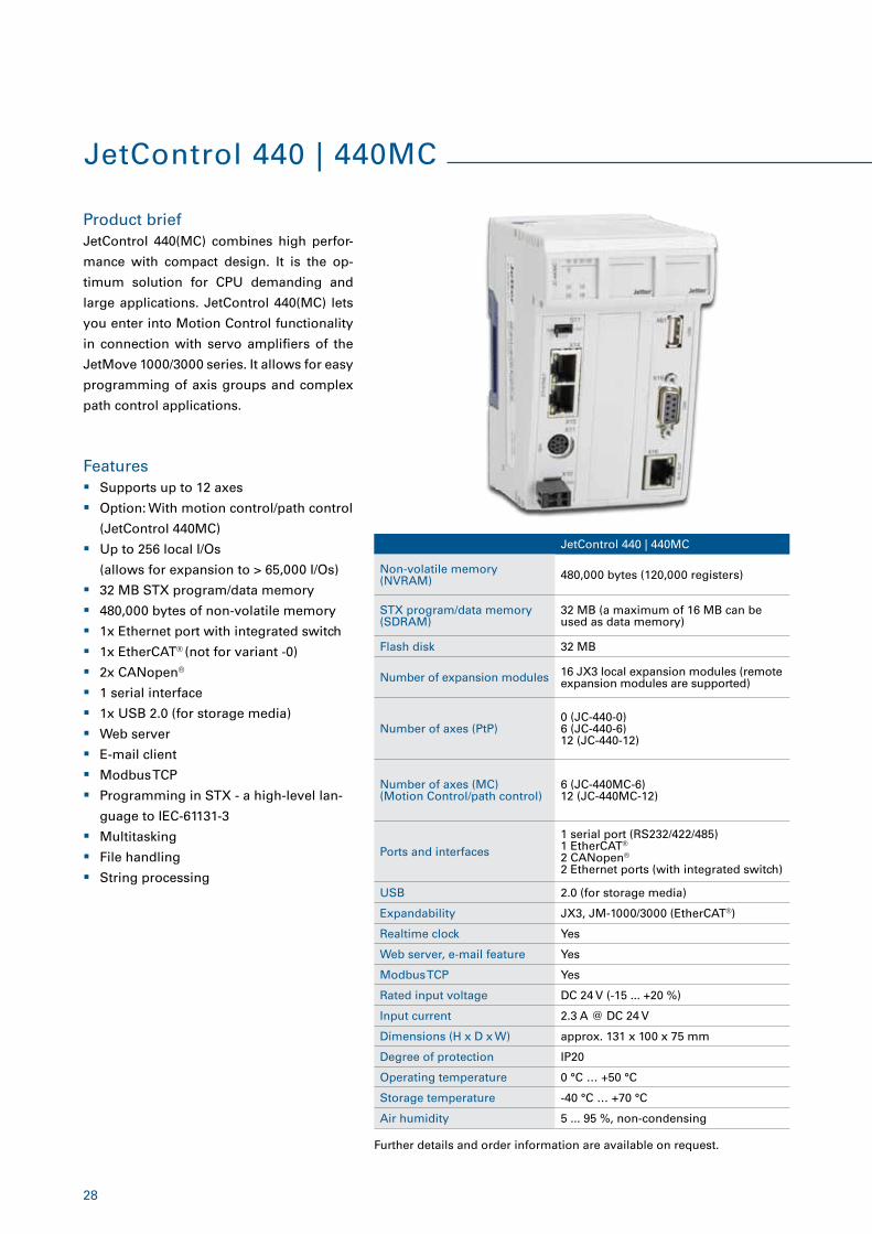
Product brief
Features
JetControl 440(MC) combines high perfor-
mance with compact design. It is the op-
timum solution for CPU demanding and
large applications. JetControl 440(MC) lets
you enter into Motion Control functionality
in connection with servo amplifiers of the
JetMove 1000/3000 series. It allows for easy
programming of axis groups and complex
path control applications.
� Supports up to 12 axes
� Option: With motion control/path control
(JetControl 440MC)
� Up to 256 local I/Os
(allows for expansion to > 65,000 I/Os)
� 32 MB STX program/data memory
� 480,000 bytes of non-volatile memory
� 1x Ethernet port with integrated switch
� 1x EtherCAT® (not for variant -0)
� 2x CANopen®
� 1 serial interface
� 1x USB 2.0 (for storage media)
� Web server
� E-mail client
� Modbus TCP
� Programming in STX - a high-level lan-
guage to IEC-61131-3
� Multitasking
� File handling
� String processing
Further details and order information are available on request.
JetControl 440 | 440MC
Non-volatile memory (NVRAM) 480,000 bytes (120,000 registers)
STX program/data memory (SDRAM)
32 MB (a maximum of 16 MB can be used as data memory)
Flash disk 32 MB
Number of expansion modules 16 JX3 local expansion modules (remote expansion modules are supported)
Number of axes (PtP)0 (JC-440-0)6 (JC-440-6) 12 (JC-440-12)
Number of axes (MC) (Motion Control/path control)
6 (JC-440MC-6)12 (JC-440MC-12)
Ports and interfaces
1 serial port (RS232/422/485)1 EtherCAT®
2 CANopen®
2 Ethernet ports (with integrated switch)
USB 2.0 (for storage media)
Expandability JX3, JM-1000/3000 (EtherCAT®)
Realtime clock Yes
Web server, e-mail feature Yes
Modbus TCP Yes
Rated input voltage DC 24 V (-15 ... +20 %)
Input current 2.3 A @ DC 24 V
Dimensions (H x D x W) approx. 131 x 100 x 75 mm
Degree of protection IP20
Operating temperature 0 °C … +50 °C
Storage temperature -40 °C … +70 °C
Air humidity 5 ... 95 %, non-condensing
JetControl 440 | 440MC
29
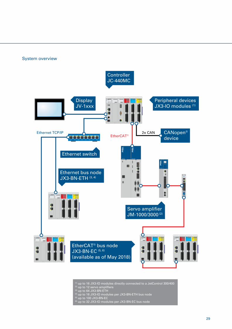
System overview
Servo ampli�erJM-1000/3000 (2)
EtherCAT® bus nodeJX3-BN-EC (5, 6)
(available as of May 2018)
DisplayJV-1xxx
Ethernet switch
CANopen®
deviceEtherCAT®Ethernet TCP/IP 2x CAN
1 2 3 4 5 6 7 8
Ethernet bus nodeJX3-BN-ETH (3, 4)
Peripheral devicesJX3-IO modules (1)
ControllerJC-440MC
(1) up to 16 JX3-IO modules directly connected to a JetControl 300/400(2) up to 12 servo ampli�ers(3) up to 64 JX3-BN-ETH (4) up to 16 JX3-IO modules per JX3-BN-ETH bus node(5) up to 100 JX3-BN-EC(6) up to 32 JX3-IO modules per JX3-BN-EC bus node
30
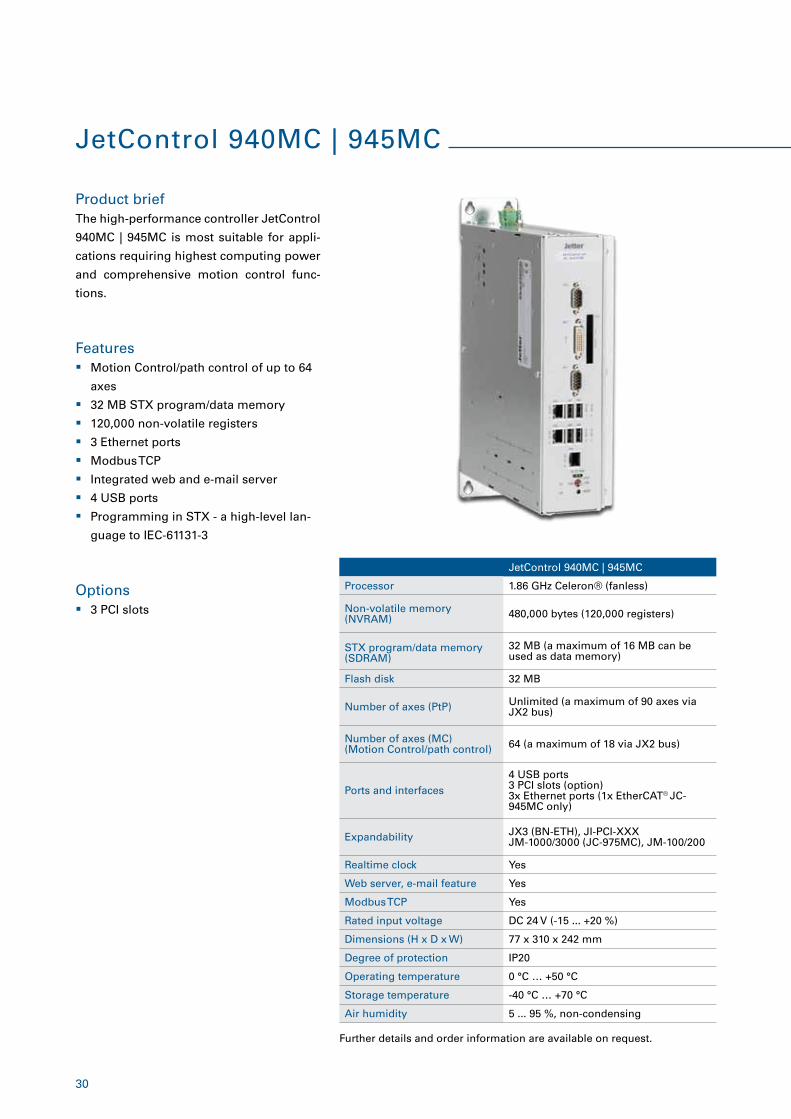
JetControl 940MC | 945MC
Processor 1.86 GHz Celeron® (fanless)
Non-volatile memory (NVRAM) 480,000 bytes (120,000 registers)
STX program/data memory (SDRAM)
32 MB (a maximum of 16 MB can be used as data memory)
Flash disk 32 MB
Number of axes (PtP) Unlimited (a maximum of 90 axes via JX2 bus)
Number of axes (MC) (Motion Control/path control) 64 (a maximum of 18 via JX2 bus)
Ports and interfaces
4 USB ports3 PCI slots (option)3x Ethernet ports (1x EtherCAT® JC-945MC only)
Expandability JX3 (BN-ETH), JI-PCI-XXX JM-1000/3000 (JC-975MC), JM-100/200
Realtime clock Yes
Web server, e-mail feature Yes
Modbus TCP Yes
Rated input voltage DC 24 V (-15 ... +20 %)
Dimensions (H x D x W) 77 x 310 x 242 mm
Degree of protection IP20
Operating temperature 0 °C … +50 °C
Storage temperature -40 °C … +70 °C
Air humidity 5 ... 95 %, non-condensing
Options � 3 PCI slots
JetControl 940MC | 945MC
Product brief
Features
The high-performance controller JetControl
940MC | 945MC is most suitable for appli-
cations requiring highest computing power
and comprehensive motion control func-
tions.
� Motion Control/path control of up to 64
axes
� 32 MB STX program/data memory
� 120,000 non-volatile registers
� 3 Ethernet ports
� Modbus TCP
� Integrated web and e-mail server
� 4 USB ports
� Programming in STX - a high-level lan-
guage to IEC-61131-3
Further details and order information are available on request.
31
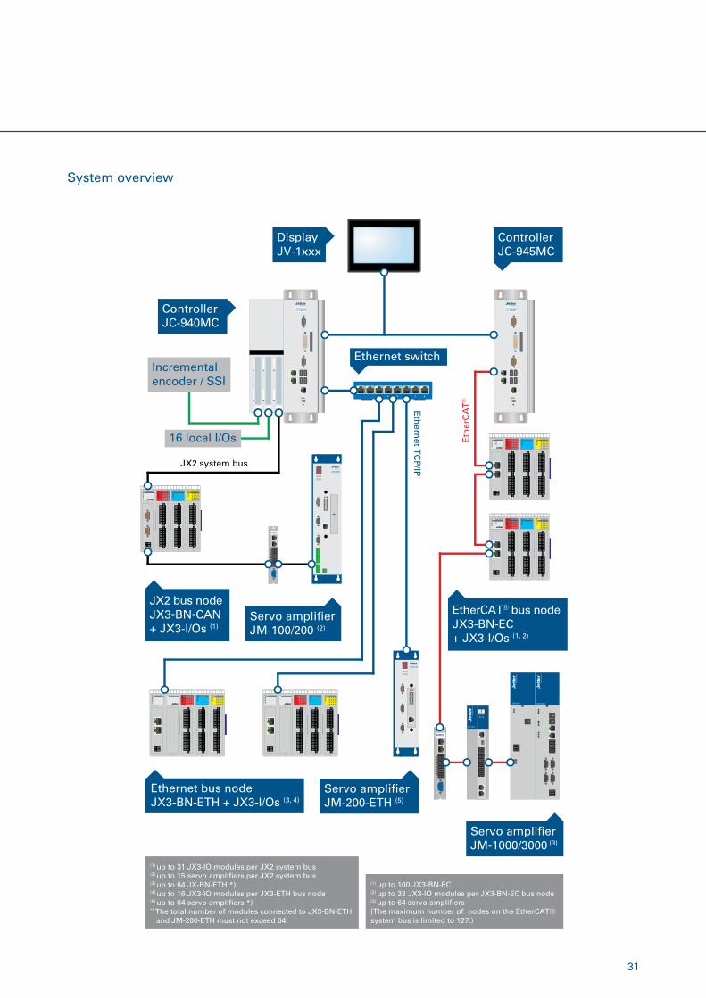
System overview
DisplayJV-1xxx
ControllerJC-940MC
ControllerJC-945MC
Servo ampli�erJM-100/200 (2)
Ethernet switchIncremental encoder / SSI
16 local I/Os Eth
erC
AT
®
Eth
ernet T
CP
/IPJX2 system bus
1 2 3 4 5 6 7 8
Servo ampli�erJM-200-ETH (5)
Servo ampli�erJM-1000/3000 (3)
Ethernet bus nodeJX3-BN-ETH + JX3-I/Os (3, 4)
JX2 bus nodeJX3-BN-CAN + JX3-I/Os (1)
EtherCAT® bus nodeJX3-BN-EC+ JX3-I/Os (1, 2)
(1) up to 31 JX3-IO modules per JX2 system bus(2) up to 15 servo ampli�ers per JX2 system bus(3)
up to 64 JX-BN-ETH *)(4) up to 16 JX3-IO modules per JX3-ETH bus node(5) up to 64 servo ampli�ers *)*) The total number of modules connected to JX3-BN-ETH and JM-200-ETH must not exceed 64.
(1) up to 100 JX3-BN-EC(2) up to 32 JX3-IO modules per JX3-BN-EC bus node(3) up to 64 servo ampli�ers(The maximum number of nodes on the EtherCAT® system bus is limited to 127.)
32
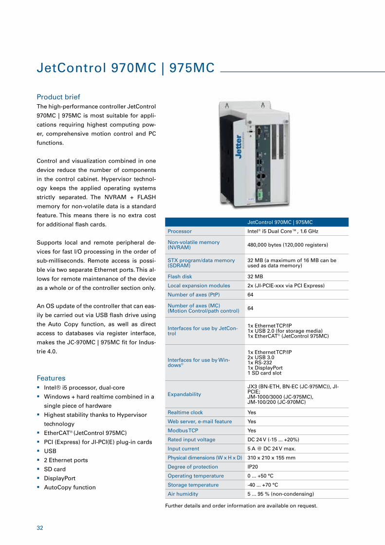
JetControl 970MC | 975MC
Processor Intel® i5 Dual Core™, 1.6 GHz
Non-volatile memory (NVRAM) 480,000 bytes (120,000 registers)
STX program/data memory (SDRAM)
32 MB (a maximum of 16 MB can be used as data memory)
Flash disk 32 MB
Local expansion modules 2x (JI-PCIE-xxx via PCI Express)
Number of axes (PtP) 64
Number of axes (MC) (Motion Control/path control) 64
Interfaces for use by JetCon-trol
1x Ethernet TCP/IP 1x USB 2.0 (for storage media)1x EtherCAT® (JetControl 975MC)
Interfaces for use by Win-dows®
1x Ethernet TCP/IP 2x USB 3.0 1x RS-2321x DisplayPort1 SD card slot
Expandability
JX3 (BN-ETH, BN-EC (JC-975MC)), JI-PCIE; JM-1000/3000 (JC-975MC), JM-100/200 (JC-970MC)
Realtime clock Yes
Web server, e-mail feature Yes
Modbus TCP Yes
Rated input voltage DC 24 V (-15 ... +20%)
Input current 5 A @ DC 24 V max.
Physical dimensions (W x H x D) 310 x 210 x 155 mm
Degree of protection IP20
Operating temperature 0 ... +50 °C
Storage temperature -40 ... +70 °C
Air humidity 5 ... 95 % (non-condensing)
JetControl 970MC | 975MC
Product brief
Features
The high-performance controller JetControl
970MC | 975MC is most suitable for appli-
cations requiring highest computing pow-
er, comprehensive motion control and PC
functions.
Control and visualization combined in one
device reduce the number of components
in the control cabinet. Hypervisor technol-
ogy keeps the applied operating systems
strictly separated. The NVRAM + FLASH
memory for non-volatile data is a standard
feature. This means there is no extra cost
for additional flash cards.
Supports local and remote peripheral de-
vices for fast I/O processing in the order of
sub-milliseconds. Remote access is possi-
ble via two separate Ethernet ports. This al-
lows for remote maintenance of the device
as a whole or of the controller section only.
An OS update of the controller that can eas-
ily be carried out via USB flash drive using
the Auto Copy function, as well as direct
access to databases via register interface,
makes the JC-970MC | 975MC fit for Indus-
trie 4.0.
� Intel® i5 processor, dual-core
� Windows + hard realtime combined in a
single piece of hardware
� Highest stability thanks to Hypervisor
technology
� EtherCAT® (JetControl 975MC)
� PCI (Express) for JI-PCI(E) plug-in cards
� USB
� 2 Ethernet ports
� SD card
� DisplayPort
� AutoCopy function
Further details and order information are available on request.
33
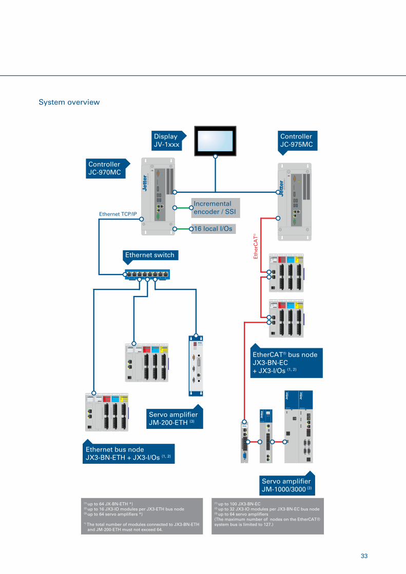
System overview
DisplayJV-1xxx
ControllerJC-970MC
ControllerJC-975MC
Ethernet switch
Incrementalencoder / SSI
16 local I/Os
Eth
erC
AT
®
1 2 3 4 5 6 7 8
Servo ampli�erJM-200-ETH (3)
Servo ampli�erJM-1000/3000 (3)
Ethernet bus nodeJX3-BN-ETH + JX3-I/Os (1, 2)
EtherCAT® bus nodeJX3-BN-EC+ JX3-I/Os (1, 2)
(1) up to 64 JX-BN-ETH *)
(2) up to 16 JX3-IO modules per JX3-ETH bus node(3) up to 64 servo ampli�ers *)
*) The total number of modules connected to JX3-BN-ETH and JM-200-ETH must not exceed 64.
(1) up to 100 JX3-BN-EC(2) up to 32 JX3-IO modules per JX3-BN-EC bus node(3) up to 64 servo ampli�ers(The maximum number of nodes on the EtherCAT® system bus is limited to 127.)
Ethernet TCP/IP
34
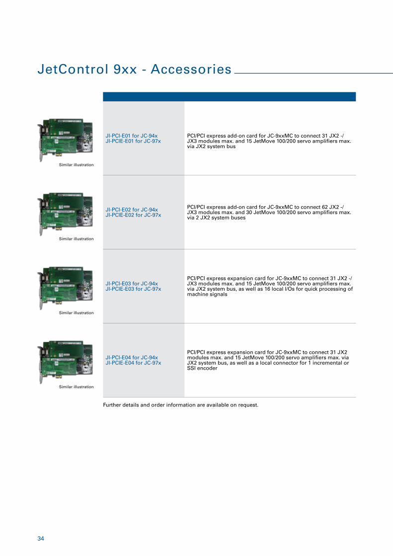
JetControl 9xx - Accessories
JI-PCI-E01 for JC-94xJI-PCIE-E01 for JC-97x
PCI/PCI express add-on card for JC-9xxMC to connect 31 JX2 -/JX3 modules max. and 15 JetMove 100/200 servo amplifiers max. via JX2 system bus
JI-PCI-E02 for JC-94xJI-PCIE-E02 for JC-97x
PCI/PCI express add-on card for JC-9xxMC to connect 62 JX2 -/JX3 modules max. and 30 JetMove 100/200 servo amplifiers max. via 2 JX2 system buses
JI-PCI-E03 for JC-94xJI-PCIE-E03 for JC-97x
PCI/PCI express expansion card for JC-9xxMC to connect 31 JX2 -/JX3 modules max. and 15 JetMove 100/200 servo amplifiers max. via JX2 system bus, as well as 16 local I/Os for quick processing of machine signals
JI-PCI-E04 for JC-94xJI-PCIE-E04 for JC-97x
PCI/PCI express expansion card for JC-9xxMC to connect 31 JX2 modules max. and 15 JetMove 100/200 servo amplifiers max. via JX2 system bus, as well as a local connector for 1 incremental or SSI encoder
Further details and order information are available on request.
Similar illustration
Similar illustration
Similar illustration
Similar illustration
35
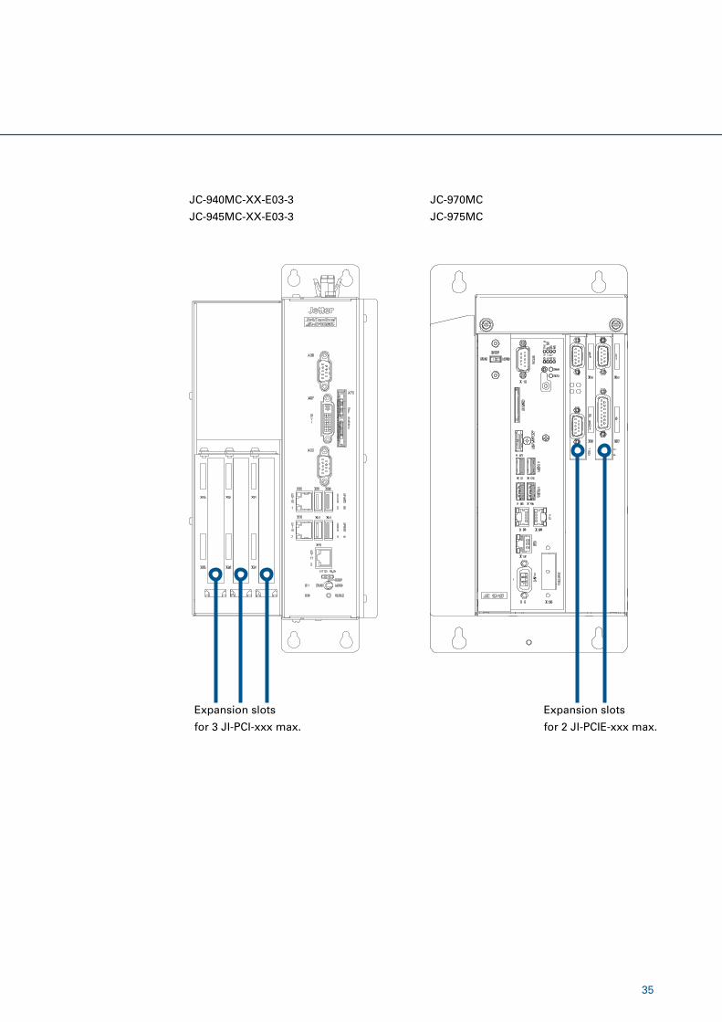
JC-940MC-XX-E03-3
JC-945MC-XX-E03-3
Expansion slots
for 3 JI-PCI-xxx max.
Expansion slots
for 2 JI-PCIE-xxx max.
JC-970MC
JC-975MC
36
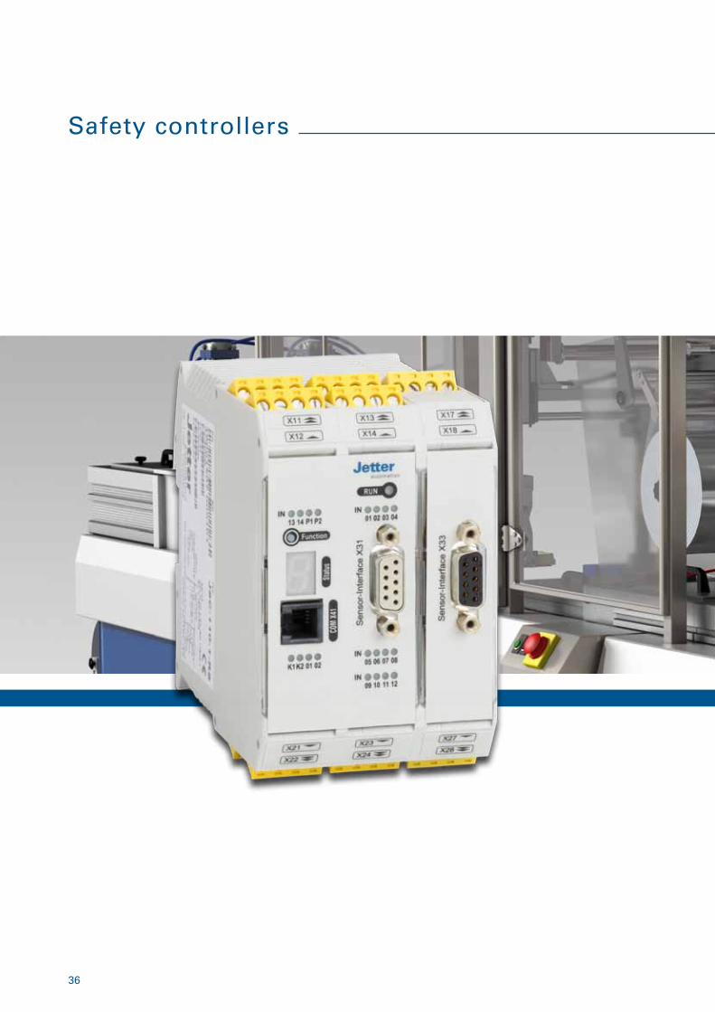
Safety controllers
37
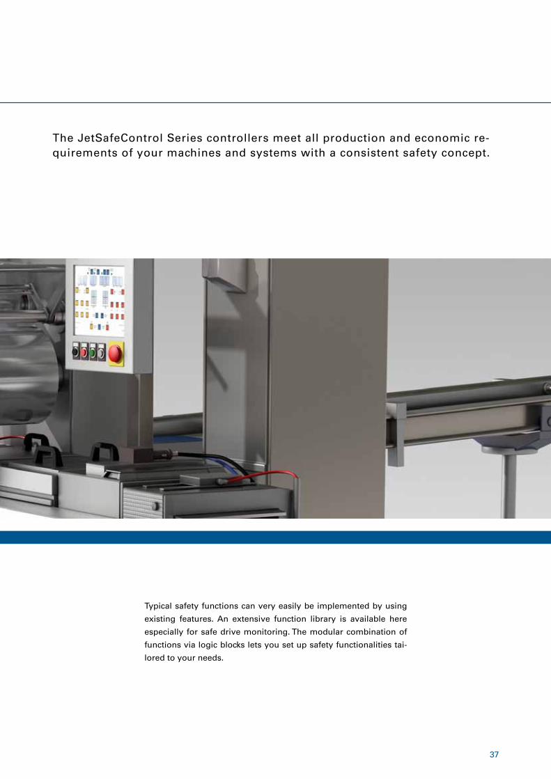
The JetSafeControl Series controllers meet all production and economic re-quirements of your machines and systems with a consistent safety concept.
Typical safety functions can very easily be implemented by using
existing features. An extensive function library is available here
especially for safe drive monitoring. The modular combination of
functions via logic blocks lets you set up safety functionalities tai-
lored to your needs.
Further details and order information are available on request.
JetSafeControl 110
Maximum number of add-on modules
2
Safe digital inputs 14
Safe digital IOs -
Safe digital outputs p-p/p-n switching 2
Safe relay outputs 2
Signaling outputs 2
Clock outputs 2
Safe axis monitoring -
Maximum number of axes -
Encoder interfaces -
Dimensions (H x D x W) 100 x 115 x 45 mm
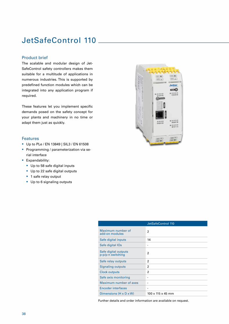
Product brief
Features
The scalable and modular design of Jet-
SafeControl safety controllers makes them
suitable for a multitude of applications in
numerous industries. This is supported by
predefined function modules which can be
integrated into any application program if
required.
These features let you implement specific
demands posed on the safety concept for
your plants and machinery in no time or
adapt them just as quickly.
� Up to PLe / EN 13849 | SIL3 / EN 61508
� Programming / parameterization via se-
rial interface
� Expandability:
� Up to 58 safe digital inputs
� Up to 22 safe digital outputs
� 1 safe relay output
� Up to 6 signaling outputs
JetSafeControl 110
38
Further details and order information are available on request.
39
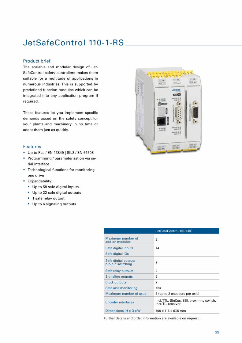
Product brief
Features � Up to PLe / EN 13849 | SIL3 / EN 61508
� Programming / parameterization via se-
rial interface
� Technological functions for monitoring
one drive
� Expandability:
� Up to 58 safe digital inputs
� Up to 22 safe digital outputs
� 1 safe relay output
� Up to 6 signaling outputs
The scalable and modular design of Jet-
SafeControl safety controllers makes them
suitable for a multitude of applications in
numerous industries. This is supported by
predefined function modules which can be
integrated into any application program if
required.
These features let you implement specific
demands posed on the safety concept for
your plants and machinery in no time or
adapt them just as quickly.
JetSafeControl 110-1-RS
Maximum number of add-on modules
2
Safe digital inputs 14
Safe digital IOs -
Safe digital outputs p-p/p-n switching 2
Safe relay outputs 2
Signaling outputs 2
Clock outputs 2
Safe axis monitoring Yes
Maximum number of axes 1 (up to 2 encoders per axis)
Encoder interfaces incl. TTL, SinCos, SSI, proximity switch, incr. TL, resolver
Dimensions (H x D x W) 100 x 115 x 67.5 mm
JetSafeControl 110-1-RS
40
Further details and order information are available on request.
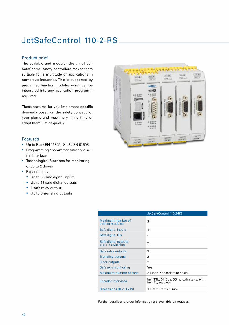
JetSafeControl 110-2-RS
Product brief
Features � Up to PLe / EN 13849 | SIL3 / EN 61508
� Programming / parameterization via se-
rial interface
� Technological functions for monitoring
of up to 2 drives
� Expandability:
� Up to 58 safe digital inputs
� Up to 22 safe digital outputs
� 1 safe relay output
� Up to 6 signaling outputs
The scalable and modular design of Jet-
SafeControl safety controllers makes them
suitable for a multitude of applications in
numerous industries. This is supported by
predefined function modules which can be
integrated into any application program if
required.
These features let you implement specific
demands posed on the safety concept for
your plants and machinery in no time or
adapt them just as quickly.
JetSafeControl 110-2-RS
Maximum number of add-on modules
2
Safe digital inputs 14
Safe digital IOs -
Safe digital outputs p-p/p-n switching 2
Safe relay outputs 2
Signaling outputs 2
Clock outputs 2
Safe axis monitoring Yes
Maximum number of axes 2 (up to 2 encoders per axis)
Encoder interfaces incl. TTL, SinCos, SSI, proximity switch, incr. TL, resolver
Dimensions (H x D x W) 100 x 115 x 112.5 mm
41
Further details and order information are available on request.
JSX1-DIO22
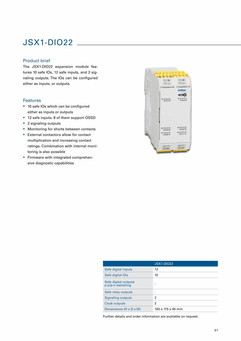
Safe digital inputs 12
Safe digital IOs 10
Safe digital outputs p-p/p-n switching -
Safe relay outputs -
Signaling outputs 2
Clock outputs 2
Dimensions (H x D x W) 100 x 115 x 45 mm
JSX1-DIO22
Product brief
Features
The JSX1-DIO22 expansion module fea-
tures 10 safe IOs, 12 safe inputs, and 2 sig-
naling outputs. The IOs can be configured
either as inputs, or outputs.
� 10 safe IOs which can be configured
either as inputs or outputs
� 12 safe inputs. 8 of them support OSSD
� 2 signaling outputs
� Monitoring for shorts between contacts
� External contactors allow for contact
multiplication and increasing contact
ratings. Combination with internal moni-
toring is also possible
� Firmware with integrated comprehen-
sive diagnostic capabilities
42
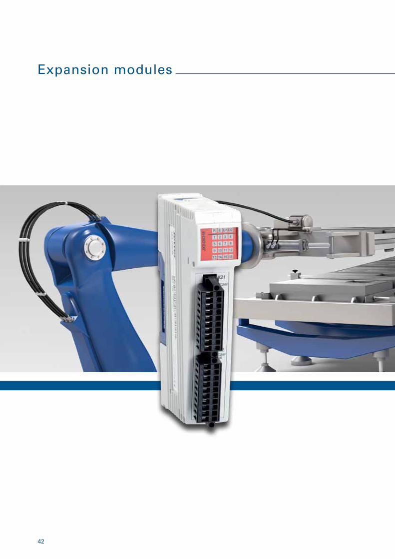
Expansion modules
43
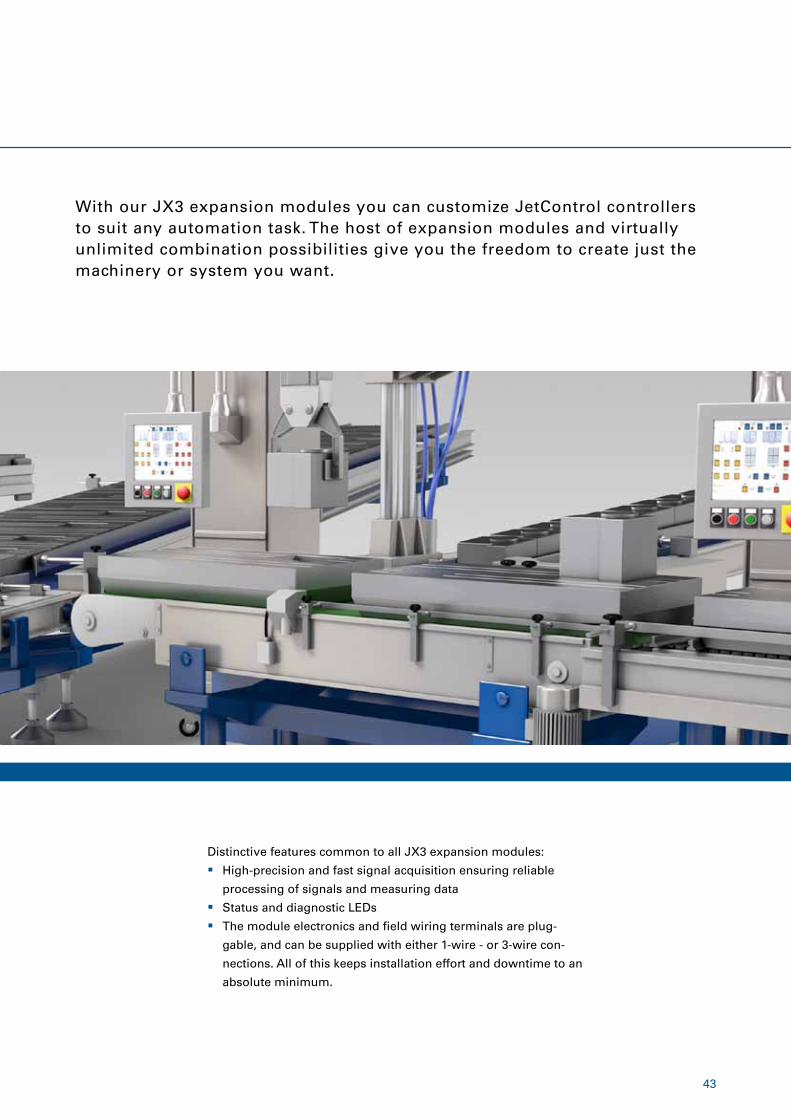
With our JX3 expansion modules you can customize JetControl controllers to suit any automation task. The host of expansion modules and virtually unlimited combination possibilities give you the freedom to create just the machinery or system you want.
� High-precision and fast signal acquisition ensuring reliable
processing of signals and measuring data
� Status and diagnostic LEDs
� The module electronics and field wiring terminals are plug-
gable, and can be supplied with either 1-wire - or 3-wire con-
nections. All of this keeps installation effort and downtime to an
absolute minimum.
Distinctive features common to all JX3 expansion modules:
44
JX3-BN-ETH
Product brief
Features
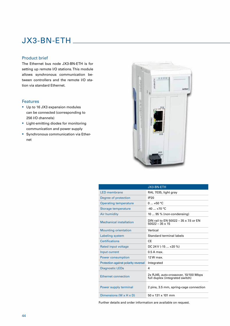
The Ethernet bus node JX3-BN-ETH is for
setting up remote I/O stations. This module
allows synchronous communication be-
tween controllers and the remote I/O sta-
tion via standard Ethernet.
� Up to 16 JX3 expansion modules
can be connected (corresponding to
256 I/O channels)
� Light-emitting diodes for monitoring
communication and power supply
� Synchronous communication via Ether-
net
JX3-BN-ETH
LED membrane RAL 7035, light gray
Degree of protection IP20
Operating temperature 0 ... +50 °C
Storage temperature -40 ... +70 °C
Air humidity 10 ... 95 % (non-condensing)
Mechanical installation DIN rail to EN 50022 – 35 x 7.5 or EN 50022 – 35 x 15
Mounting orientation Vertical
Labeling system Standard terminal labels
Certifications CE
Rated input voltage DC 24 V (-15 ... +20 %)
Input current 0.5 A max.
Power consumption 12 W max.
Protection against polarity reversal Integrated
Diagnostic LEDs 4
Ethernet connection 2x RJ45, auto-crossover, 10/100 Mbps full duplex (integrated switch)
Power supply terminal 2 pins, 3.5 mm, spring-cage connection
Dimensions (W x H x D) 50 x 131 x 101 mm
Further details and order information are available on request.
45
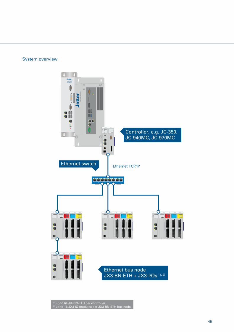
System overview
Controller, e.g. JC-350, JC-940MC, JC-970MC
1 2 3 4 5 6 7 8
Ethernet switch
Ethernet bus nodeJX3-BN-ETH + JX3-I/Os (1, 2)
Ethernet TCP/IP
(1) up to 64 JX-BN-ETH per controller(2) up to 16 JX3-IO modules per JX3-BN-ETH bus node
46
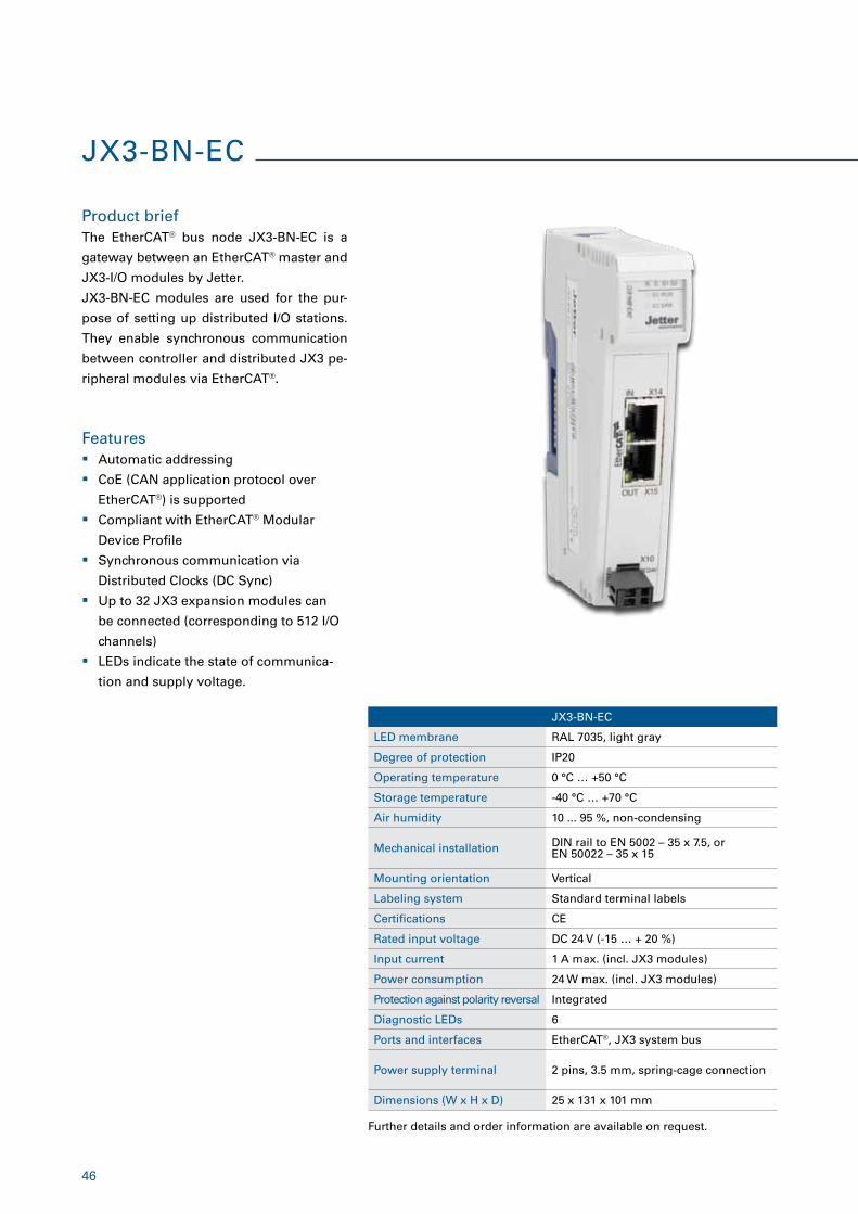
Product briefThe EtherCAT® bus node JX3-BN-EC is a
gateway between an EtherCAT® master and
JX3-I/O modules by Jetter.
JX3-BN-EC modules are used for the pur-
pose of setting up distributed I/O stations.
They enable synchronous communication
between controller and distributed JX3 pe-
ripheral modules via EtherCAT®.
Features � Automatic addressing
� CoE (CAN application protocol over
EtherCAT®) is supported
� Compliant with EtherCAT® Modular
Device Profile
� Synchronous communication via
Distributed Clocks (DC Sync)
� Up to 32 JX3 expansion modules can
be connected (corresponding to 512 I/O
channels)
� LEDs indicate the state of communica-
tion and supply voltage.
JX3-BN-EC
LED membrane RAL 7035, light gray
Degree of protection IP20
Operating temperature 0 °C … +50 °C
Storage temperature -40 °C … +70 °C
Air humidity 10 ... 95 %, non-condensing
Mechanical installation DIN rail to EN 5002 – 35 x 7.5, or EN 50022 – 35 x 15
Mounting orientation Vertical
Labeling system Standard terminal labels
Certifications CE
Rated input voltage DC 24 V (-15 … + 20 %)
Input current 1 A max. (incl. JX3 modules)
Power consumption 24 W max. (incl. JX3 modules)
Protection against polarity reversal Integrated
Diagnostic LEDs 6
Ports and interfaces EtherCAT®, JX3 system bus
Power supply terminal 2 pins, 3.5 mm, spring-cage connection
Dimensions (W x H x D) 25 x 131 x 101 mm
Further details and order information are available on request.
JX3-BN-EC
47
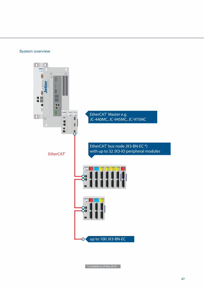
System overview
EtherCAT®
EtherCAT® Master e.g. JC-440MC, JC-945MC, JC-975MC
up to 100 JX3-BN-EC
EtherCAT® bus node JX3-BN-EC *)with up to 32 JX3-IO peripheral modules
*) available as of May 2018
48
JX3-BN-CAN
LED membrane RAL 7035, light gray
Degree of protection IP20
Operating temperature 0 ... +50 °C
Storage temperature -40 ... +70 °C
Air humidity 10 ... 95 % (non-condensing)
Mechanical installation DIN rail to EN 50022 – 35 x 7.5 or EN 50022 – 35 x 15
Mounting orientation Vertical
Labeling system Standard terminal labels
Certifications CE
Rated input voltage DC 24 V (-15 ... +20 %)
Input current 0.5 A max.
Power consumption 12 W max.
Protection against polarity reversal Integrated
Diagnostic LEDs 4
BUS-IN port 9-pin male Sub-D connector
BUS-OUT port 9-pin female Sub-D connector
Power supply terminal 2 pins, 3.5 mm, spring-cage connection
Dimensions (W x H x D) 25 x 131 x 101 mm
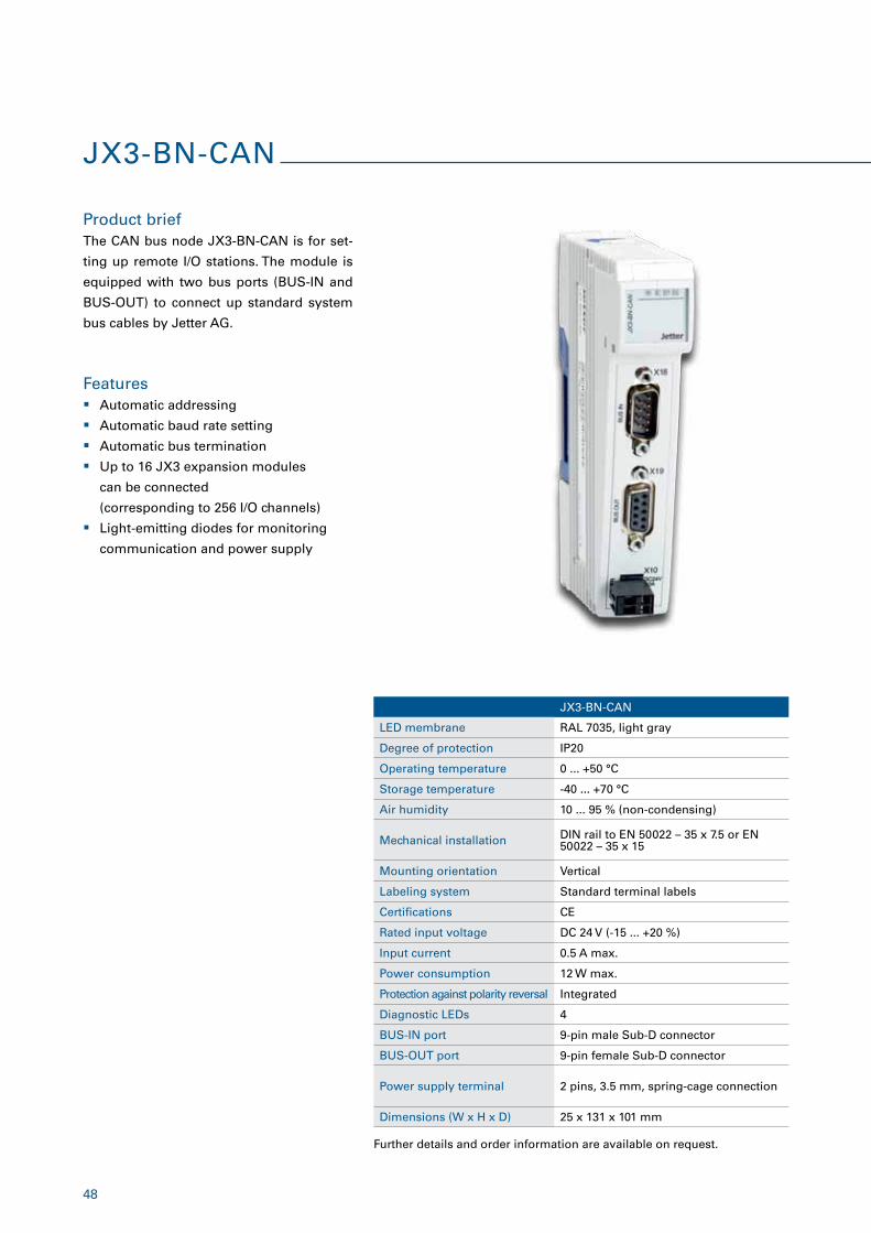
JX3-BN-CAN
Product brief
Features
The CAN bus node JX3-BN-CAN is for set-
ting up remote I/O stations. The module is
equipped with two bus ports (BUS-IN and
BUS-OUT) to connect up standard system
bus cables by Jetter AG.
� Automatic addressing
� Automatic baud rate setting
� Automatic bus termination
� Up to 16 JX3 expansion modules
can be connected
(corresponding to 256 I/O channels)
� Light-emitting diodes for monitoring
communication and power supply
Further details and order information are available on request.
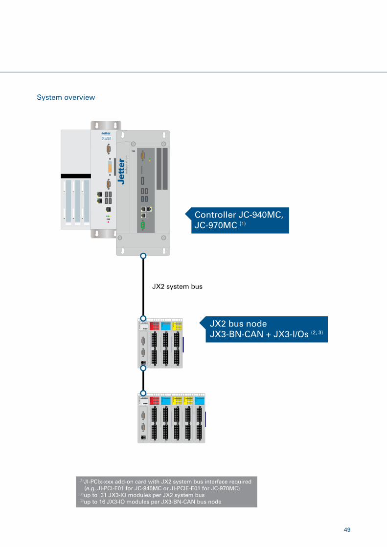
49
System overview
Controller JC-940MC, JC-970MC (1)
JX2 bus nodeJX3-BN-CAN + JX3-I/Os (2, 3)
JX2 system bus
(1) JI-PCIx-xxx add-on card with JX2 system bus interface required (e.g. JI-PCI-E01 for JC-940MC or JI-PCIE-E01 for JC-970MC)(2) up to 31 JX3-IO modules per JX2 system bus(3) up to 16 JX3-IO modules per JX3-BN-CAN bus node
50
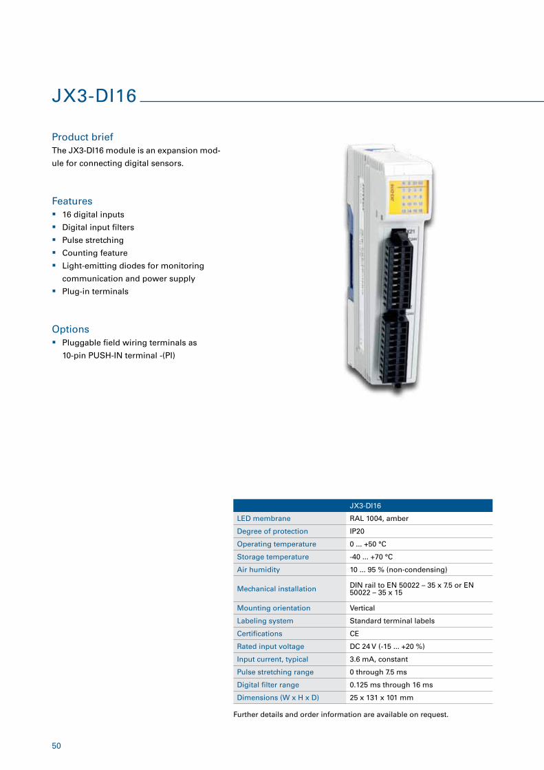
JX3-DI16
Product brief
Features
The JX3-DI16 module is an expansion mod-
ule for connecting digital sensors.
� 16 digital inputs
� Digital input filters
� Pulse stretching
� Counting feature
� Light-emitting diodes for monitoring
communication and power supply
� Plug-in terminals
JX3-DI16
LED membrane RAL 1004, amber
Degree of protection IP20
Operating temperature 0 ... +50 °C
Storage temperature -40 ... +70 °C
Air humidity 10 ... 95 % (non-condensing)
Mechanical installation DIN rail to EN 50022 – 35 x 7.5 or EN 50022 – 35 x 15
Mounting orientation Vertical
Labeling system Standard terminal labels
Certifications CE
Rated input voltage DC 24 V (-15 ... +20 %)
Input current, typical 3.6 mA, constant
Pulse stretching range 0 through 7.5 ms
Digital filter range 0.125 ms through 16 ms
Dimensions (W x H x D) 25 x 131 x 101 mm
Further details and order information are available on request.
Options � Pluggable field wiring terminals as
10-pin PUSH-IN terminal -(PI)
51
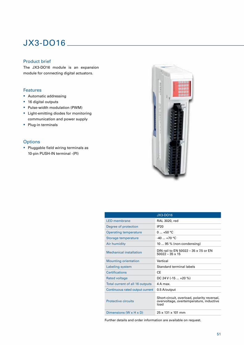
JX3-DO16
LED membrane RAL 3020, red
Degree of protection IP20
Operating temperature 0 ... +50 °C
Storage temperature -40 ... +70 °C
Air humidity 10 ... 95 % (non-condensing)
Mechanical installation DIN rail to EN 50022 – 35 x 7.5 or EN 50022 – 35 x 15
Mounting orientation Vertical
Labeling system Standard terminal labels
Certifications CE
Rated voltage DC 24 V (-15 ... +20 %)
Total current of all 16 outputs 4 A max.
Continuous rated output current 0.5 A/output
Protective circuitsShort-circuit, overload, polarity reversal, overvoltage, overtemperature, inductive load
Dimensions (W x H x D) 25 x 131 x 101 mm
JX3-DO16
Product brief
Features
The JX3-DO16 module is an expansion
module for connecting digital actuators.
� Automatic addressing
� 16 digital outputs
� Pulse-width modulation (PWM)
� Light-emitting diodes for monitoring
communication and power supply
� Plug-in terminals
Further details and order information are available on request.
Options � Pluggable field wiring terminals as
10-pin PUSH-IN terminal -(PI)
52
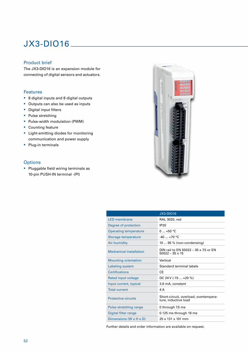
JX3-DIO16
Product brief
Features
The JX3-DIO16 is an expansion module for
connecting of digital sensors and actuators.
� 8 digital inputs and 8 digital outputs
� Outputs can also be used as inputs
� Digital input filters
� Pulse stretching
� Pulse-width modulation (PWM)
� Counting feature
� Light-emitting diodes for monitoring
communication and power supply
� Plug-in terminals
JX3-DIO16
LED membrane RAL 3020, red
Degree of protection IP20
Operating temperature 0 ... +50 °C
Storage temperature -40 ... +70 °C
Air humidity 10 ... 95 % (non-condensing)
Mechanical installation DIN rail to EN 50022 – 35 x 7.5 or EN 50022 – 35 x 15
Mounting orientation Vertical
Labeling system Standard terminal labels
Certifications CE
Rated input voltage DC 24 V (-15 ... +20 %)
Input current, typical 3.6 mA, constant
Total current 4 A
Protective circuits Short-circuit, overload, overtempera-ture, inductive load
Pulse stretching range 0 through 7.5 ms
Digital filter range 0.125 ms through 16 ms
Dimensions (W x H x D) 25 x 131 x 101 mm
Further details and order information are available on request.
Options � Pluggable field wiring terminals as
10-pin PUSH-IN terminal -(PI)
53
JX3-AI4
LED membrane RAL 6018, yellow-green
Degree of protection IP20
Operating temperature 0 ... +50 °C
Storage temperature -40 ... +70 °C
Air humidity 10 ... 95 % (non-condensing)
Mechanical installation DIN rail to EN 50022 – 35 x 7.5 or EN 50022 – 35 x 15
Mounting orientation Vertical
Labeling system Standard terminal labels
Certifications CE
Number of analog inputs 4
Voltage range 0 ... 10 V, -10 ... +10 V
Current range 0 ... 20 mA, 4 ... 20 mA
Resolution 16 bits
Accuracy Better than 0.5 % across the whole operating temperature range
Conversion time 1 ms for all 4 channels (collective con-version)
Maximum input frequency 200 Hz
Electrical isolation Option
Dimensions (W x H x D) 25 x 131 x 101 mm
JX3-AI4
Product brief
Features
Options
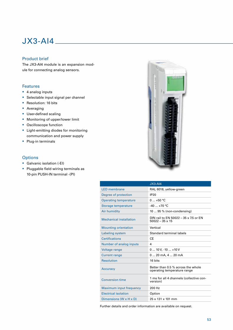
The JX3-AI4 module is an expansion mod-
ule for connecting analog sensors.
� 4 analog inputs
� Selectable input signal per channel
� Resolution: 16 bits
� Averaging
� User-defined scaling
� Monitoring of upper/lower limit
� Oscilloscope function
� Light-emitting diodes for monitoring
communication and power supply
� Plug-in terminals
� Galvanic isolation (-EI)
� Pluggable field wiring terminals as
10-pin PUSH-IN terminal -(PI)
Further details and order information are available on request.
54
JX3-AO4
Product brief
Features
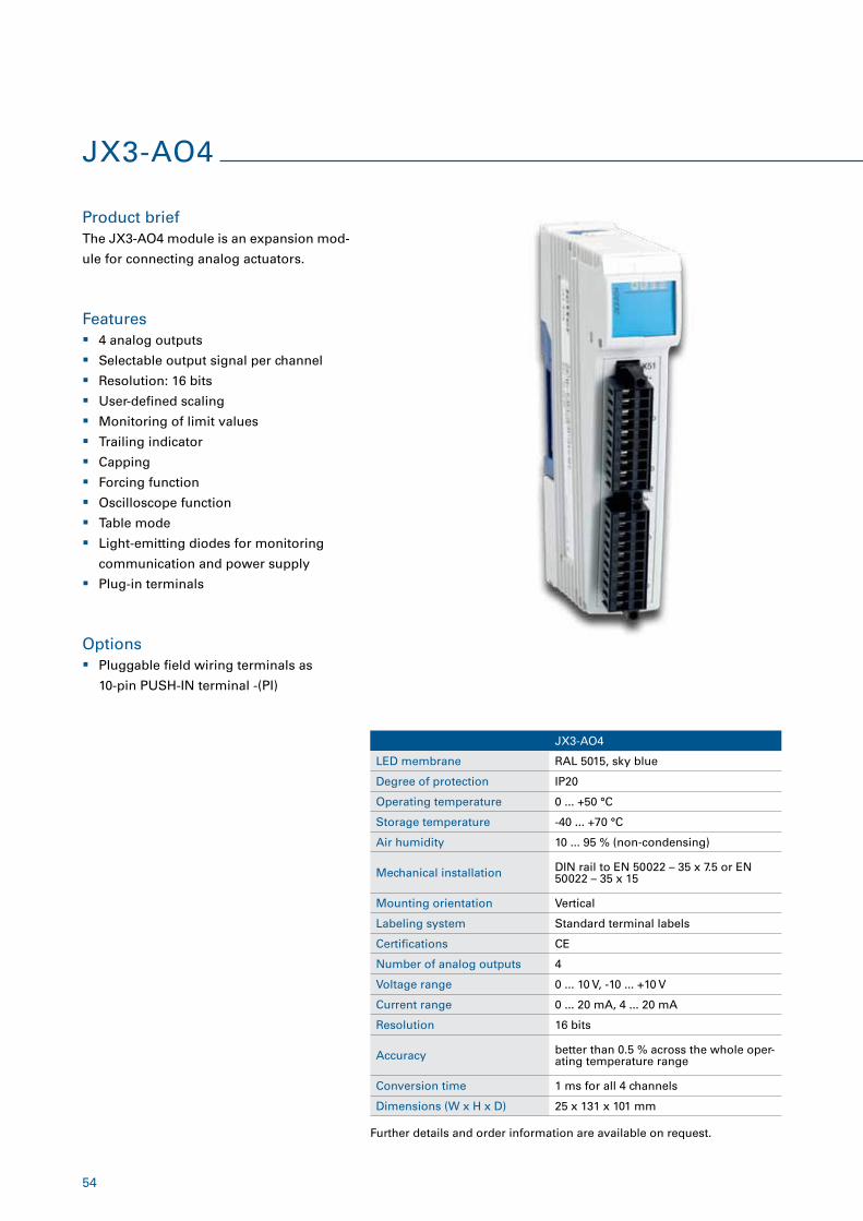
The JX3-AO4 module is an expansion mod-
ule for connecting analog actuators.
� 4 analog outputs
� Selectable output signal per channel
� Resolution: 16 bits
� User-defined scaling
� Monitoring of limit values
� Trailing indicator
� Capping
� Forcing function
� Oscilloscope function
� Table mode
� Light-emitting diodes for monitoring
communication and power supply
� Plug-in terminals
JX3-AO4
LED membrane RAL 5015, sky blue
Degree of protection IP20
Operating temperature 0 ... +50 °C
Storage temperature -40 ... +70 °C
Air humidity 10 ... 95 % (non-condensing)
Mechanical installation DIN rail to EN 50022 – 35 x 7.5 or EN 50022 – 35 x 15
Mounting orientation Vertical
Labeling system Standard terminal labels
Certifications CE
Number of analog outputs 4
Voltage range 0 ... 10 V, -10 ... +10 V
Current range 0 ... 20 mA, 4 ... 20 mA
Resolution 16 bits
Accuracy better than 0.5 % across the whole oper-ating temperature range
Conversion time 1 ms for all 4 channels
Dimensions (W x H x D) 25 x 131 x 101 mm
Further details and order information are available on request.
Options � Pluggable field wiring terminals as
10-pin PUSH-IN terminal -(PI)
55
JX3-THI2-RTD
LED membrane RAL 6018, yellow-green
Degree of protection IP20
Operating temperature 0 ... +50 °C
Storage temperature -40 ... +70 °C
Air humidity 10 ... 95 % (non-condensing)
Mechanical installation DIN rail to EN 50022 – 35 x 7.5 or EN 50022 – 35 x 15
Mounting orientation Vertical
Labeling system Standard terminal labels
Certifications CE
Signal range -50 ... 850 °C
Resolution 0.01 °C
Accuracy0.5 ... 450 °C, 1 °C at 450 °C or higher (typically 0.1 % of the measured value + 0.0025 % of the measuring range)
Effective conversion time for both channels
Pt100: 90 to 150 ms slow mode, 8 to 15 ms fast mode Pt1000: 100 to 200 ms slow mode, 10 to 20 ms fast mode
Connection technology 2-, 3- and 4-wire technology
Electrical isolation Option
Dimensions (W x H x D) 25 x 131 x 101 mm
JX3-THI2-RTD
Product brief
Features
Options
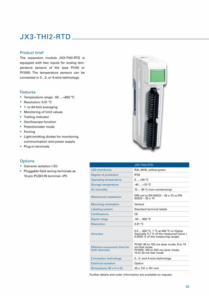
The expansion module JX3-THI2-RTD is
equipped with two inputs for analog tem-
perature sensors of the type Pt100 or
Pt1000. The temperature sensors can be
connected in 2-, 3- or 4-wire technology.
� Temperature range: -50 ... +850 °C
� Resolution: 0.01 °C
� 1- to 64-fold averaging
� Monitoring of limit values
� Trailing indicator
� Oscilloscope function
� Potentiometer mode
� Forcing
� Light-emitting diodes for monitoring
communication and power supply
� Plug-in terminals
� Galvanic isolation (-EI)
� Pluggable field wiring terminals as
10-pin PUSH-IN terminal -(PI)
Further details and order information are available on request.
56
JX3-THI2-TC
Product brief
Features
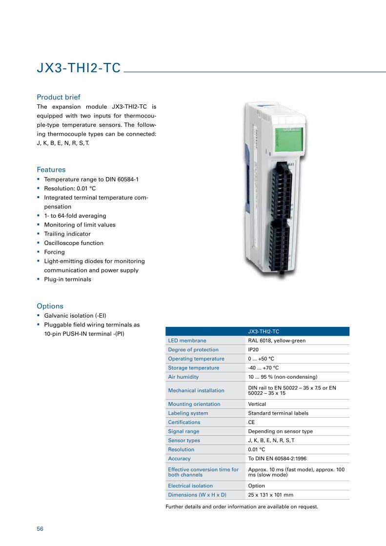
The expansion module JX3-THI2-TC is
equipped with two inputs for thermocou-
ple-type temperature sensors. The follow-
ing thermocouple types can be connected:
J, K, B, E, N, R, S, T.
� Temperature range to DIN 60584-1
� Resolution: 0.01 °C
� Integrated terminal temperature com-
pensation
� 1- to 64-fold averaging
� Monitoring of limit values
� Trailing indicator
� Oscilloscope function
� Forcing
� Light-emitting diodes for monitoring
communication and power supply
� Plug-in terminals
JX3-THI2-TC
LED membrane RAL 6018, yellow-green
Degree of protection IP20
Operating temperature 0 ... +50 °C
Storage temperature -40 ... +70 °C
Air humidity 10 ... 95 % (non-condensing)
Mechanical installation DIN rail to EN 50022 – 35 x 7.5 or EN 50022 – 35 x 15
Mounting orientation Vertical
Labeling system Standard terminal labels
Certifications CE
Signal range Depending on sensor type
Sensor types J, K, B, E, N, R, S, T
Resolution 0.01 °C
Accuracy To DIN EN 60584-2:1996
Effective conversion time for both channels
Approx. 10 ms (fast mode), approx. 100 ms (slow mode)
Electrical isolation Option
Dimensions (W x H x D) 25 x 131 x 101 mm
Options � Galvanic isolation (-EI)
� Pluggable field wiring terminals as
10-pin PUSH-IN terminal -(PI)
Further details and order information are available on request.
57
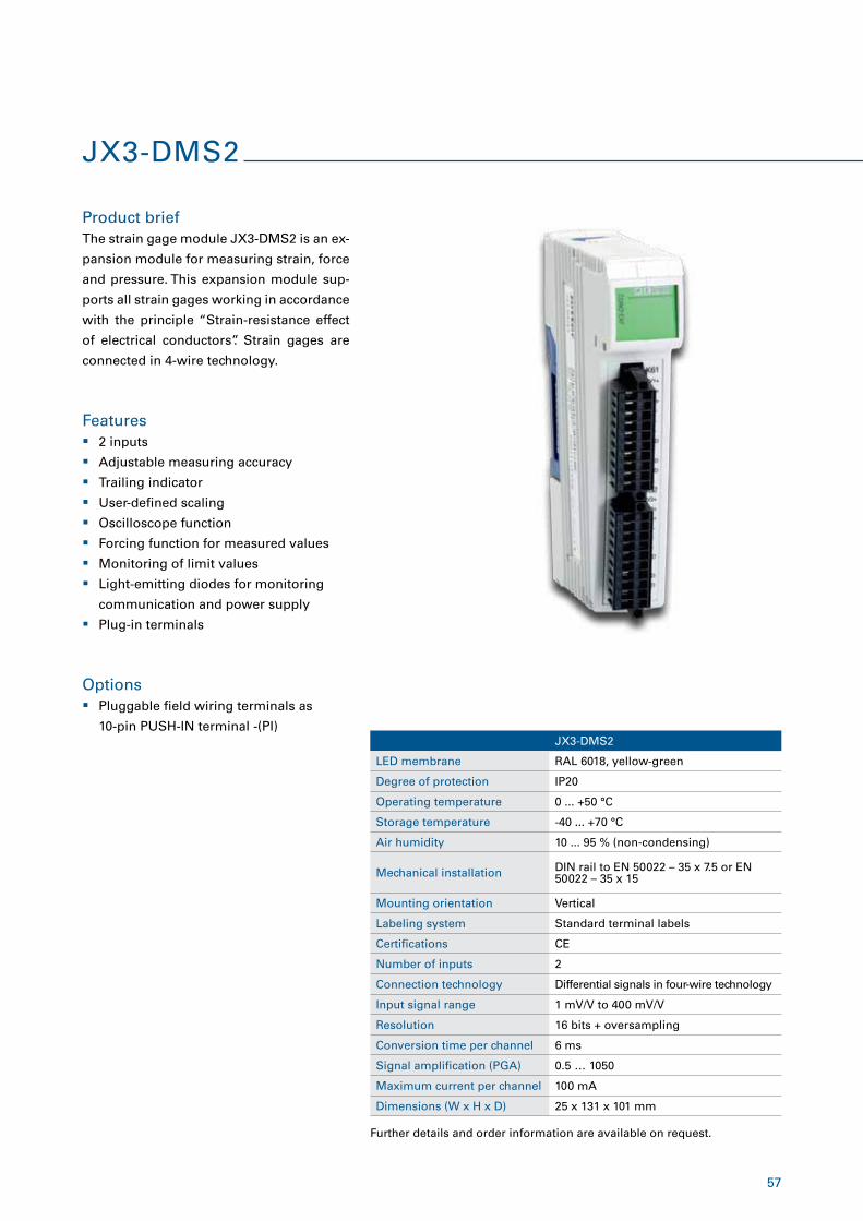
JX3-DMS2
LED membrane RAL 6018, yellow-green
Degree of protection IP20
Operating temperature 0 ... +50 °C
Storage temperature -40 ... +70 °C
Air humidity 10 ... 95 % (non-condensing)
Mechanical installation DIN rail to EN 50022 – 35 x 7.5 or EN 50022 – 35 x 15
Mounting orientation Vertical
Labeling system Standard terminal labels
Certifications CE
Number of inputs 2
Connection technology Differential signals in four-wire technology
Input signal range 1 mV/V to 400 mV/V
Resolution 16 bits + oversampling
Conversion time per channel 6 ms
Signal amplification (PGA) 0.5 … 1050
Maximum current per channel 100 mA
Dimensions (W x H x D) 25 x 131 x 101 mm
JX3-DMS2
Product brief
Features
The strain gage module JX3-DMS2 is an ex-
pansion module for measuring strain, force
and pressure. This expansion module sup-
ports all strain gages working in accordance
with the principle “Strain-resistance effect
of electrical conductors”. Strain gages are
connected in 4-wire technology.
� 2 inputs
� Adjustable measuring accuracy
� Trailing indicator
� User-defined scaling
� Oscilloscope function
� Forcing function for measured values
� Monitoring of limit values
� Light-emitting diodes for monitoring
communication and power supply
� Plug-in terminals
Further details and order information are available on request.
Options � Pluggable field wiring terminals as
10-pin PUSH-IN terminal -(PI)
58
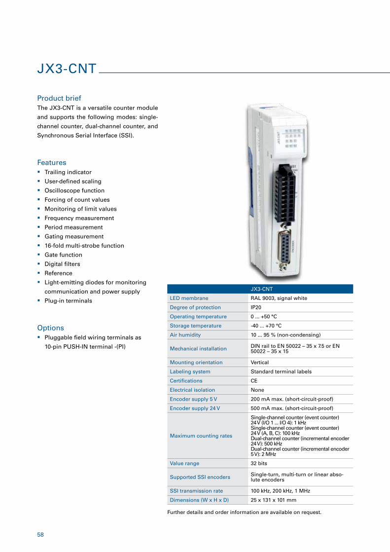
JX3-CNT
Product brief
Features
The JX3-CNT is a versatile counter module
and supports the following modes: single-
channel counter, dual-channel counter, and
Synchronous Serial Interface (SSI).
� Trailing indicator
� User-defined scaling
� Oscilloscope function
� Forcing of count values
� Monitoring of limit values
� Frequency measurement
� Period measurement
� Gating measurement
� 16-fold multi-strobe function
� Gate function
� Digital filters
� Reference
� Light-emitting diodes for monitoring
communication and power supply
� Plug-in terminals
JX3-CNT
LED membrane RAL 9003, signal white
Degree of protection IP20
Operating temperature 0 ... +50 °C
Storage temperature -40 ... +70 °C
Air humidity 10 ... 95 % (non-condensing)
Mechanical installation DIN rail to EN 50022 – 35 x 7.5 or EN 50022 – 35 x 15
Mounting orientation Vertical
Labeling system Standard terminal labels
Certifications CE
Electrical isolation None
Encoder supply 5 V 200 mA max. (short-circuit-proof)
Encoder supply 24 V 500 mA max. (short-circuit-proof)
Maximum counting rates
Single-channel counter (event counter) 24 V (I/O 1 ... I/O 4): 1 kHz Single-channel counter (event counter) 24 V (A, B, C): 100 kHz Dual-channel counter (incremental encoder 24 V): 500 kHz Dual-channel counter (incremental encoder 5 V): 2 MHz
Value range 32 bits
Supported SSI encoders Single-turn, multi-turn or linear abso-lute encoders
SSI transmission rate 100 kHz, 200 kHz, 1 MHz
Dimensions (W x H x D) 25 x 131 x 101 mm
Further details and order information are available on request.
Options � Pluggable field wiring terminals as
10-pin PUSH-IN terminal -(PI)
59
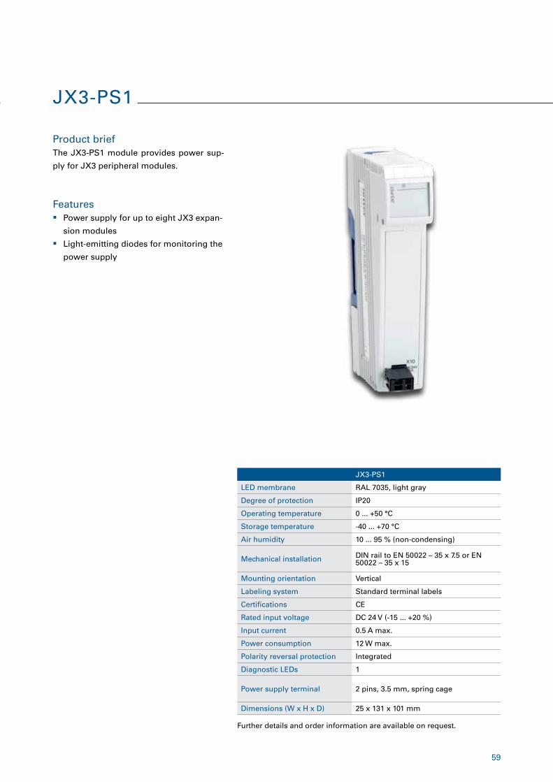
JX3-PS1
LED membrane RAL 7035, light gray
Degree of protection IP20
Operating temperature 0 ... +50 °C
Storage temperature -40 ... +70 °C
Air humidity 10 ... 95 % (non-condensing)
Mechanical installation DIN rail to EN 50022 – 35 x 7.5 or EN 50022 – 35 x 15
Mounting orientation Vertical
Labeling system Standard terminal labels
Certifications CE
Rated input voltage DC 24 V (-15 ... +20 %)
Input current 0.5 A max.
Power consumption 12 W max.
Polarity reversal protection Integrated
Diagnostic LEDs 1
Power supply terminal 2 pins, 3.5 mm, spring cage
Dimensions (W x H x D) 25 x 131 x 101 mm
JX3-PS1
Product brief
Features
The JX3-PS1 module provides power sup-
ply for JX3 peripheral modules.
� Power supply for up to eight JX3 expan-
sion modules
� Light-emitting diodes for monitoring the
power supply
Further details and order information are available on request.
60
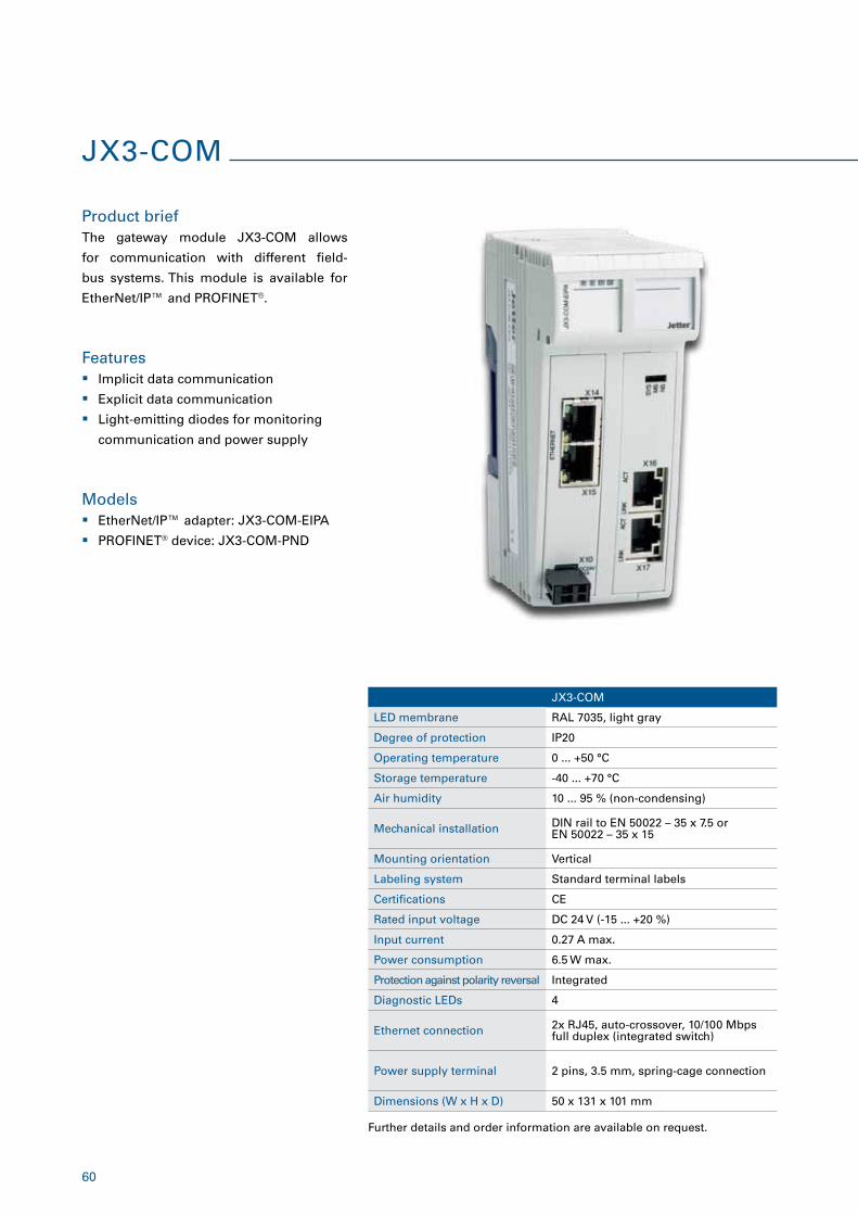
JX3-COM
Product brief
Features
Models
The gateway module JX3-COM allows
for communication with different field-
bus systems. This module is available for
EtherNet/IP™ and PROFINET®.
� Implicit data communication
� Explicit data communication
� Light-emitting diodes for monitoring
communication and power supply
� EtherNet/IP™ adapter: JX3-COM-EIPA
� PROFINET® device: JX3-COM-PND
Further details and order information are available on request.
JX3-COM
LED membrane RAL 7035, light gray
Degree of protection IP20
Operating temperature 0 ... +50 °C
Storage temperature -40 ... +70 °C
Air humidity 10 ... 95 % (non-condensing)
Mechanical installation DIN rail to EN 50022 – 35 x 7.5 or EN 50022 – 35 x 15
Mounting orientation Vertical
Labeling system Standard terminal labels
Certifications CE
Rated input voltage DC 24 V (-15 ... +20 %)
Input current 0.27 A max.
Power consumption 6.5 W max.
Protection against polarity reversal Integrated
Diagnostic LEDs 4
Ethernet connection 2x RJ45, auto-crossover, 10/100 Mbps full duplex (integrated switch)
Power supply terminal 2 pins, 3.5 mm, spring-cage connection
Dimensions (W x H x D) 50 x 131 x 101 mm
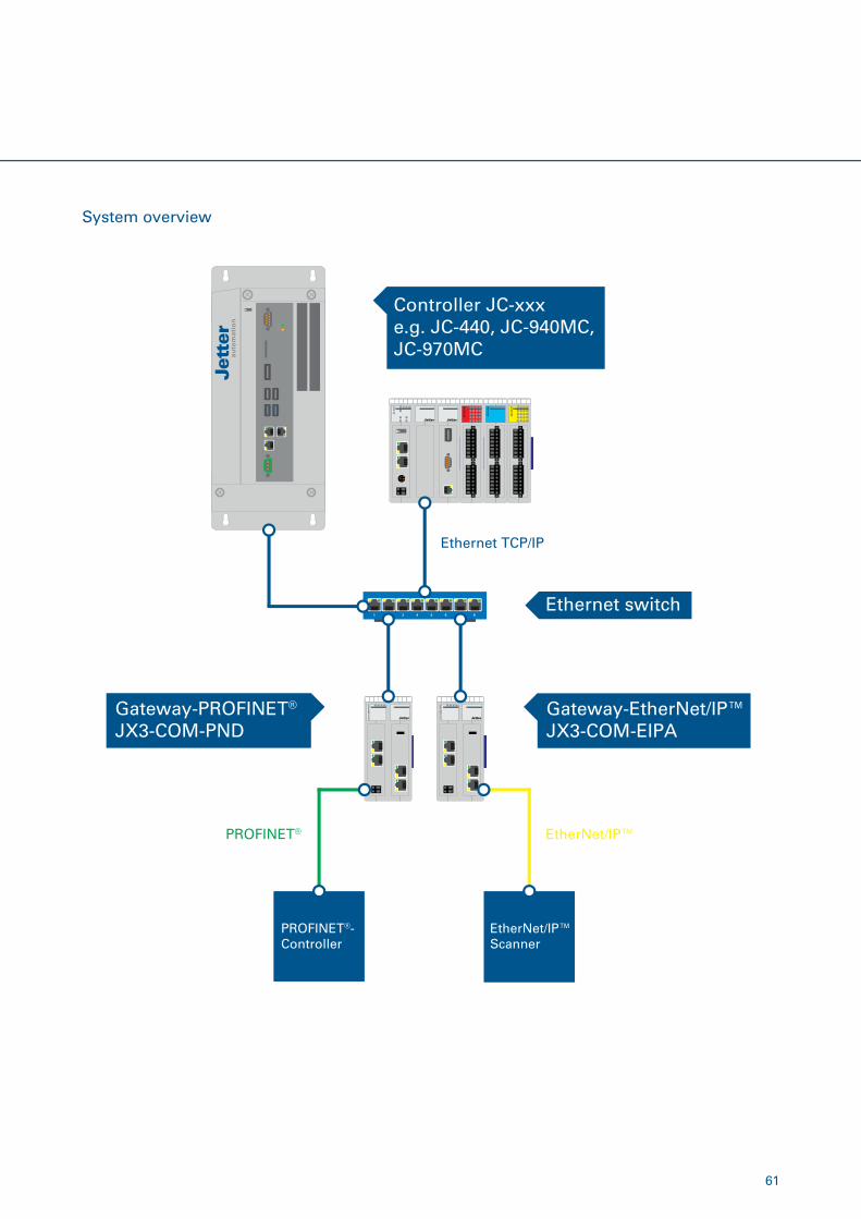
61
System overview
Controller JC-xxxe.g. JC-440, JC-940MC, JC-970MC
Gateway-PROFINET®
JX3-COM-PNDGateway-EtherNet/IP™JX3-COM-EIPA
1 2 3 4 5 6 7 8Ethernet switch
PROFINET®-Controller
EtherNet/IP™Scanner
Ethernet TCP/IP
EtherNet/IP™PROFINET®
62
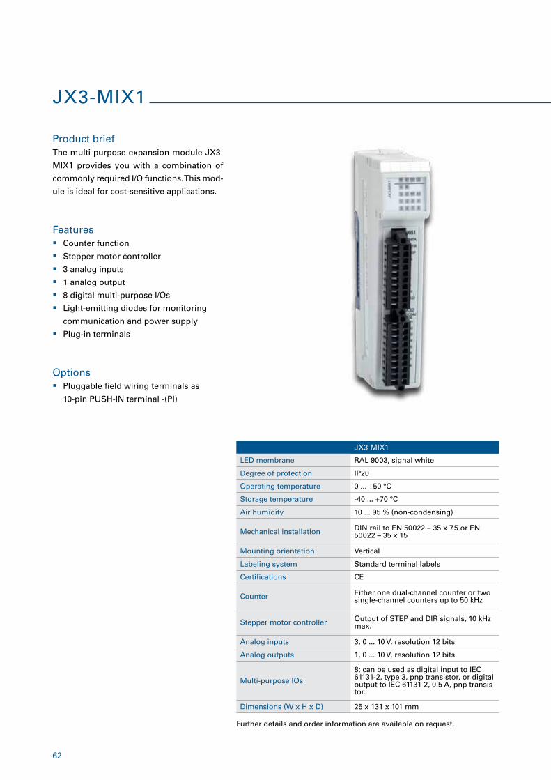
JX3-MIX1
Product brief
Features
The multi-purpose expansion module JX3-
MIX1 provides you with a combination of
commonly required I/O functions. This mod-
ule is ideal for cost-sensitive applications.
� Counter function
� Stepper motor controller
� 3 analog inputs
� 1 analog output
� 8 digital multi-purpose I/Os
� Light-emitting diodes for monitoring
communication and power supply
� Plug-in terminals
JX3-MIX1
LED membrane RAL 9003, signal white
Degree of protection IP20
Operating temperature 0 ... +50 °C
Storage temperature -40 ... +70 °C
Air humidity 10 ... 95 % (non-condensing)
Mechanical installation DIN rail to EN 50022 – 35 x 7.5 or EN 50022 – 35 x 15
Mounting orientation Vertical
Labeling system Standard terminal labels
Certifications CE
Counter Either one dual-channel counter or two single-channel counters up to 50 kHz
Stepper motor controller Output of STEP and DIR signals, 10 kHz max.
Analog inputs 3, 0 ... 10 V, resolution 12 bits
Analog outputs 1, 0 ... 10 V, resolution 12 bits
Multi-purpose IOs
8; can be used as digital input to IEC 61131-2, type 3, pnp transistor, or digital output to IEC 61131-2, 0.5 A, pnp transis-tor.
Dimensions (W x H x D) 25 x 131 x 101 mm
Options � Pluggable field wiring terminals as
10-pin PUSH-IN terminal -(PI)
Further details and order information are available on request.
63
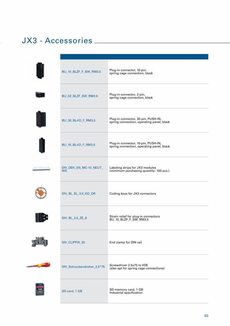
JX3 - Accessories
BU_10_BLZF_F_SW_RM3.5 Plug-in connector, 10-pin,spring cage connection, black
BU_02_BLZF_SW_RM3.5 Plug-in connector, 2-pin,spring cage connection, black
BU_30_BL-I/O_F_RM3.5 Plug-in connector, 30-pin, PUSH-IN,spring connection, operating panel, black
BU_10_BL-I/O_F_RM3.5 Plug-in connector, 10-pin, PUSH-IN, spring connection, operating panel, black
DIV_DEK_5/5_MC-10_NEUT_WS
Labeling strips for JX3 modules(minimum purchasing quantity: 100 pcs.)
DIV_BL_SL_3.5_KO_OR Coding keys for JX3 connectors
DIV_BL_3.5_ZE_8 Strain relief for plug-in connectorsBU_10_BLZF_F_SW_RM3.5
DIV_CLIPFIX_35 End clamp for DIN rail
DIV_Schraubendreher_2,5*75 Screwdriver 2.5x75 to VDE(also apt for spring cage connections)
SD card, 1 GB SD memory card, 1 GB Industrial specification
64
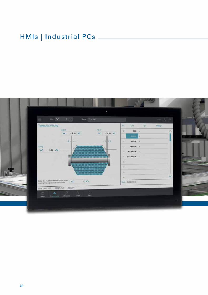
HMIs | Industrial PCs
65
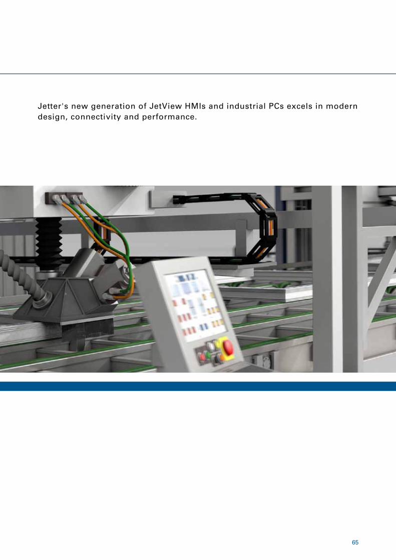
Jetter's new generation of JetView HMIs and industrial PCs excels in modern design, connectivity and performance.
66
JetView 1005 | 1007 | 1010
Product brief
Features
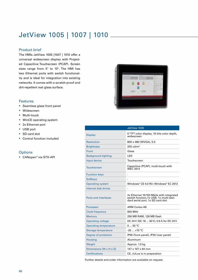
The HMIs JetView 1005 |1007 | 1010 offer a
universal widescreen display with Project-
ed Capacitive Touchscreen (PCAP). Screen
sizes range from 5" to 10". The HMI has
two Ethernet ports with switch functional-
ity and is ideal for integration into existing
networks. It comes with a scratch-proof and
dirt-repellent real glass surface.
� Seamless glass front panel
� Widescreen
� Multi-touch
� WinCE operating system
� 2x Ethernet port
� USB port
� SD card slot
� Control function included
Further details and order information are available on request.
JetView 1005
Display 5" TFT color display, 16 bits color depth, widescreen
Resolution 800 x 480 (WVGA), 5:3
Brightness 200 cd/m²
Front Glass
Background lighting LED
Input device Touchscreen
Touchscreen Capacitive (PCAP), multi-touch with WEC 2013
Function keys -
Softkeys -
Operating system Windows® CE 6.0 R3 / Windows® EC 2013
Internal disk drives -
Ports and interfaces2x Ethernet 10/100 Mbits with integrated switch function,1x USB, 1x multi-stan-dard serial port, 1x SD card slot
Processor ARM Cortex A8
Clock frequency 600 MHz
Memory 256 MB RAM, 128 MB flash
Operating voltage DC 24 V (DC 18 ... 30 V), 0.6 A for DC 24 V
Operating temperature 0 ... 50 °C
Storage temperature -20 ... +70 °C
Degree of protection IP65 (front panel), IP20 (rear panel)
Housing Aluminum
Weight Approx. 1.0 kg
Dimensions (W x H x D) 147 x 107 x 64 mm
Certifications CE, cULus is in preparation
Options � CANopen® via STX-API
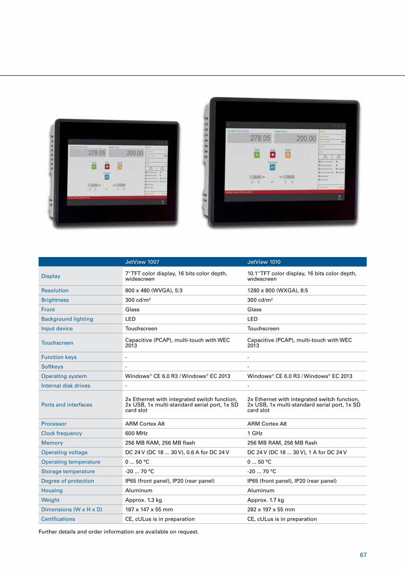
67
Further details and order information are available on request.
JetView 1007 JetView 1010
Display 7" TFT color display, 16 bits color depth, widescreen
10.1" TFT color display, 16 bits color depth, widescreen
Resolution 800 x 480 (WVGA), 5:3 1280 x 800 (WXGA), 8:5
Brightness 300 cd/m² 300 cd/m²
Front Glass Glass
Background lighting LED LED
Input device Touchscreen Touchscreen
Touchscreen Capacitive (PCAP), multi-touch with WEC 2013
Capacitive (PCAP), multi-touch with WEC 2013
Function keys - -
Softkeys - -
Operating system Windows® CE 6.0 R3 / Windows® EC 2013 Windows® CE 6.0 R3 / Windows® EC 2013
Internal disk drives - -
Ports and interfaces2x Ethernet with integrated switch function, 2x USB, 1x multi-standard serial port, 1x SD card slot
2x Ethernet with integrated switch function, 2x USB, 1x multi-standard serial port, 1x SD card slot
Processor ARM Cortex A8 ARM Cortex A8
Clock frequency 600 MHz 1 GHz
Memory 256 MB RAM, 256 MB flash 256 MB RAM, 256 MB flash
Operating voltage DC 24 V (DC 18 ... 30 V), 0.6 A for DC 24 V DC 24 V (DC 18 ... 30 V), 1 A for DC 24 V
Operating temperature 0 ... 50 °C 0 ... 50 °C
Storage temperature -20 ... 70 °C -20 ... 70 °C
Degree of protection IP65 (front panel), IP20 (rear panel) IP65 (front panel), IP20 (rear panel)
Housing Aluminum Aluminum
Weight Approx. 1.3 kg Approx. 1.7 kg
Dimensions (W x H x D) 187 x 147 x 55 mm 282 x 197 x 55 mm
Certifications CE, cULus is in preparation CE, cULus is in preparation
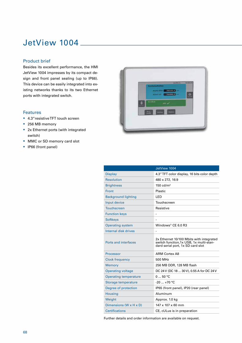
68
JetView 1004
Product brief
Features
Besides its excellent performance, the HMI
JetView 1004 impresses by its compact de-
sign and front panel sealing (up to IP66).
This device can be easily integrated into ex-
isting networks thanks to its two Ethernet
ports with integrated switch.
� 4.3“resistive TFT touch screen
� 256 MB memory
� 2x Ethernet ports (with integrated
switch)
� MMC or SD memory card slot
� IP66 (front panel)
JetView 1004
Display 4.3” TFT color display, 16 bits color depth
Resolution 480 x 272, 16:9
Brightness 150 cd/m²
Front Plastic
Background lighting LED
Input device Touchscreen
Touchscreen Resistive
Function keys -
Softkeys -
Operating system Windows® CE 6.0 R3
Internal disk drives -
Ports and interfaces2x Ethernet 10/100 Mbits with integrated switch function,1x USB, 1x multi-stan-dard serial port, 1x SD card slot
Processor ARM Cortex A8
Clock frequency 500 MHz
Memory 256 MB DDR, 128 MB flash
Operating voltage DC 24 V (DC 18 ... 30 V), 0.55 A for DC 24 V
Operating temperature 0 ... 50 °C
Storage temperature -20 ... +70 °C
Degree of protection IP65 (front panel), IP20 (rear panel)
Housing Aluminum
Weight Approx. 1.0 kg
Dimensions (W x H x D) 147 x 107 x 60 mm
Certifications CE, cULus is in preparation
Further details and order information are available on request.
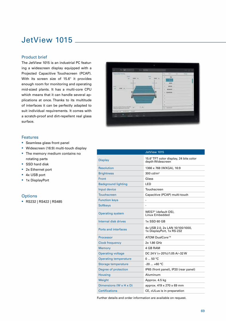
69
JetView 1015
Product brief
Features
Options
The JetView 1015 is an industrial PC featur-
ing a widescreen display equipped with a
Projected Capacitive Touchscreen (PCAP).
With its screen size of 15.6" it provides
enough room for monitoring and operating
mid-sized plants. It has a multi-core CPU
which means that it can handle several ap-
plications at once. Thanks to its multitude
of interfaces it can be perfectly adapted to
suit individual requirements. It comes with
a scratch-proof and dirt-repellent real glass
surface.
� Seamless glass front panel
� Widescreen (16:9) multi-touch display
� The memory medium contains no
rotating parts
� SSD hard disk
� 2x Ethernet port
� 4x USB port
� 1x DisplayPort
� RS232 | RS422 | RS485
Further details and order information are available on request.
JetView 1015
Display 15.6" TFT color display, 24 bits color depth Widescreen
Resolution 1366 x 768 (WXGA), 16:9
Brightness 300 cd/m²
Front Glass
Background lighting LED
Input device Touchscreen
Touchscreen Capacitive (PCAP) multi-touch
Function keys -
Softkeys -
Operating system WES7® (default OS),Linux Embedded
Internal disk drives 1x SSD 60 GB
Ports and interfaces 4x USB 2.0, 2x LAN 10/100/1000, 1x DisplayPort, 1x RS-232
Processor ATOM DualCore™
Clock frequency 2x 1.86 GHz
Memory 4 GB RAM
Operating voltage DC 24 V (+-20%)/1.05 A/~32 W
Operating temperature 0 ... 50 °C
Storage temperature -20 ... +60 °C
Degree of protection IP65 (front panel), IP20 (rear panel)
Housing Aluminum
Weight Approx. 4.5 kg
Dimensions (W x H x D) approx. 419 x 270 x 69 mm
Certifications CE, cULus is in preparation
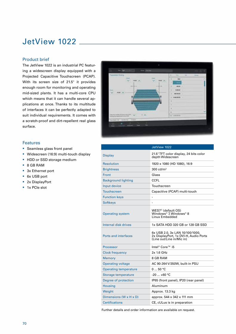
70
JetView 1022
Product brief
Features
The JetView 1022 is an industrial PC featur-
ing a widescreen display equipped with a
Projected Capacitive Touchscreen (PCAP).
With its screen size of 21.5" it provides
enough room for monitoring and operating
mid-sized plants. It has a multi-core CPU
which means that it can handle several ap-
plications at once. Thanks to its multitude
of interfaces it can be perfectly adapted to
suit individual requirements. It comes with
a scratch-proof and dirt-repellent real glass
surface.
� Seamless glass front panel
� Widescreen (16:9) multi-touch display
� HDD or SSD storage medium
� 8 GB RAM
� 3x Ethernet port
� 6x USB port
� 2x DisplayPort
� 1x PCIe slot
Further details and order information are available on request.
JetView 1022
Display 21.5" TFT color display, 24 bits color depth Widescreen
Resolution 1920 x 1080 (HD 1080), 16:9
Brightness 300 cd/m²
Front Glass
Background lighting CCFL
Input device Touchscreen
Touchscreen Capacitive (PCAP) multi-touch
Function keys -
Softkeys -
Operating systemWES7® (default OS)Windows® 7, Windows® 8Linux Embedded
Internal disk drives 1x SATA HDD 320 GB or 128 GB SSD
Ports and interfaces6x USB 2.0, 3x LAN 10/100/1000, 2x DisplayPort, 1x DVI-H, Audio Ports (Line out/Line in/Mic in)
Processor Intel® Core™ i5
Clock frequency 2x 1.6 GHz
Memory 8 GB RAM
Operating voltage AC 90-264 V/350W, built-in PSU
Operating temperature 0 ... 50 °C
Storage temperature -20 ... +60 °C
Degree of protection IP65 (front panel), IP20 (rear panel)
Housing Aluminum
Weight Approx. 13.3 kg
Dimensions (W x H x D) approx. 544 x 342 x 111 mm
Certifications CE, cULus is in preparation
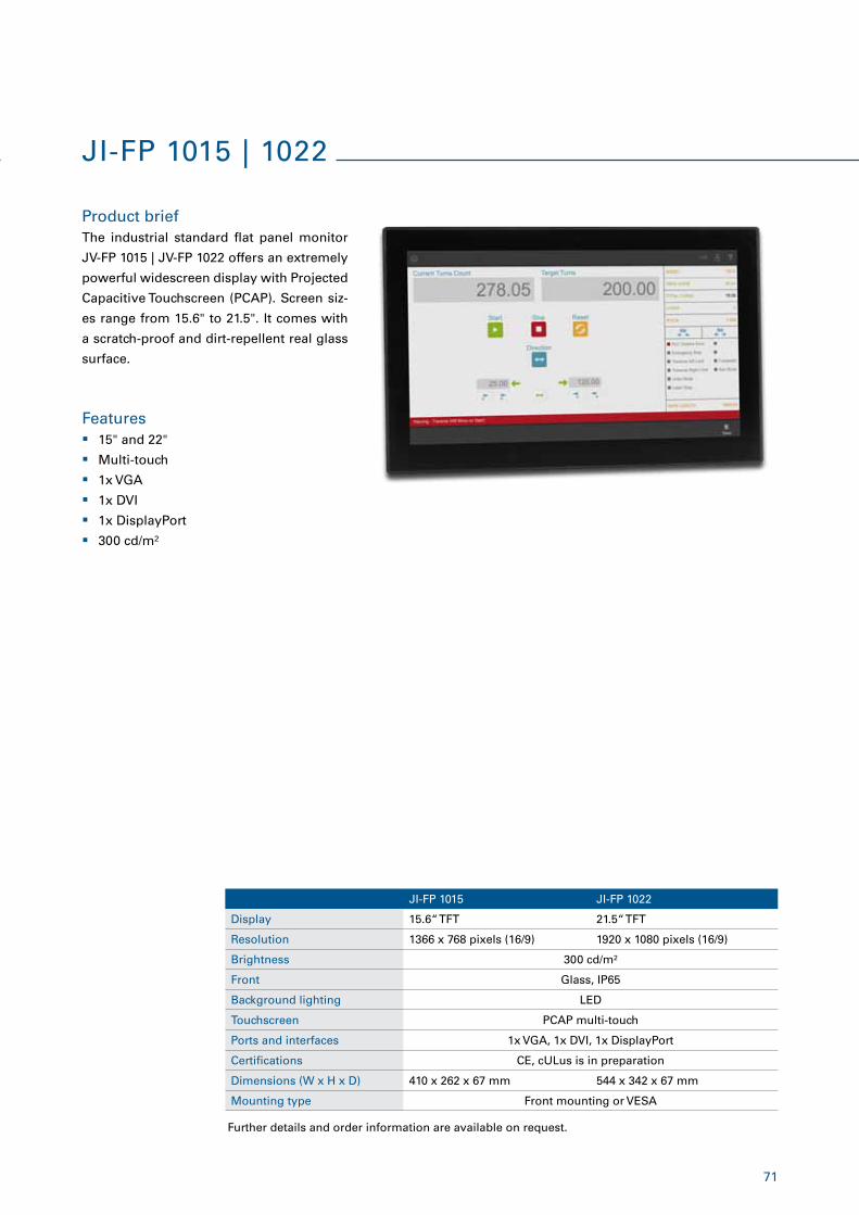
71
Product brief
Features
The industrial standard flat panel monitor
JV-FP 1015 | JV-FP 1022 offers an extremely
powerful widescreen display with Projected
Capacitive Touchscreen (PCAP). Screen siz-
es range from 15.6" to 21.5". It comes with
a scratch-proof and dirt-repellent real glass
surface.
� 15" and 22"
� Multi-touch
� 1x VGA
� 1x DVI
� 1x DisplayPort
� 300 cd/m²
JI-FP 1015 JI-FP 1022
Display 15.6“ TFT 21.5“ TFT
Resolution 1366 x 768 pixels (16/9) 1920 x 1080 pixels (16/9)
Brightness 300 cd/m²
Front Glass, IP65
Background lighting LED
Touchscreen PCAP multi-touch
Ports and interfaces 1x VGA, 1x DVI, 1x DisplayPort
Certifications CE, cULus is in preparation
Dimensions (W x H x D) 410 x 262 x 67 mm 544 x 342 x 67 mm
Mounting type Front mounting or VESA
JI-FP 1015 | 1022
Further details and order information are available on request.
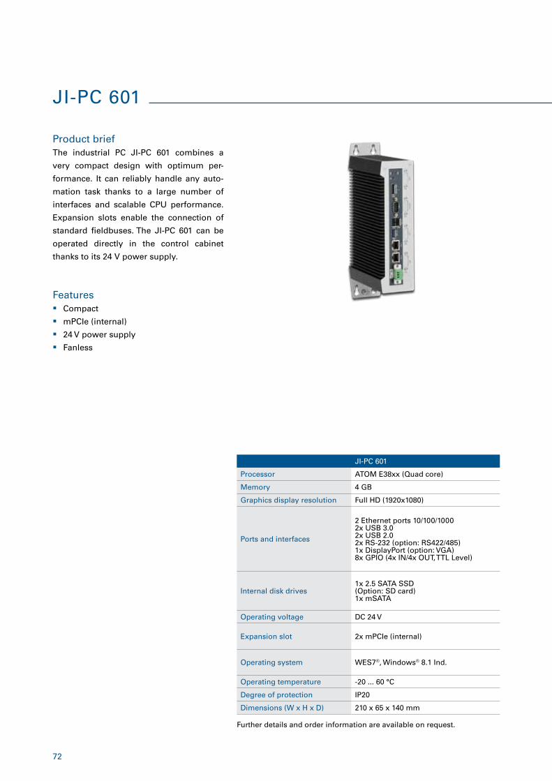
72
JI-PC 601
Processor ATOM E38xx (Quad core)
Memory 4 GB
Graphics display resolution Full HD (1920x1080)
Ports and interfaces
2 Ethernet ports 10/100/10002x USB 3.02x USB 2.02x RS-232 (option: RS422/485)1x DisplayPort (option: VGA)8x GPIO (4x IN/4x OUT, TTL Level)
Internal disk drives 1x 2.5 SATA SSD (Option: SD card)1x mSATA
Operating voltage DC 24 V
Expansion slot 2x mPCIe (internal)
Operating system WES7®, Windows® 8.1 Ind.
Operating temperature -20 ... 60 °C
Degree of protection IP20
Dimensions (W x H x D) 210 x 65 x 140 mm
JI-PC 601
Product brief
Features
The industrial PC JI-PC 601 combines a
very compact design with optimum per-
formance. It can reliably handle any auto-
mation task thanks to a large number of
interfaces and scalable CPU performance.
Expansion slots enable the connection of
standard fieldbuses. The JI-PC 601 can be
operated directly in the control cabinet
thanks to its 24 V power supply.
� Compact
� mPCIe (internal)
� 24 V power supply
� Fanless
Further details and order information are available on request.
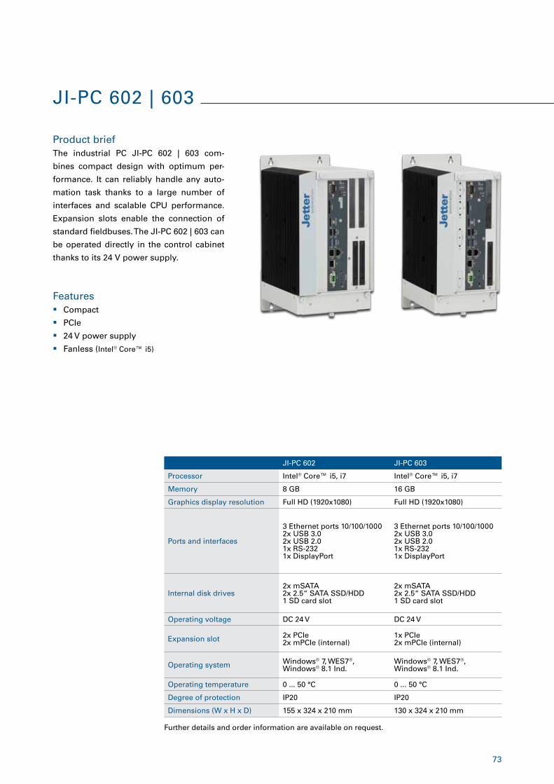
73
JI-PC 602 JI-PC 603
Processor Intel® Core™ i5, i7 Intel® Core™ i5, i7
Memory 8 GB 16 GB
Graphics display resolution Full HD (1920x1080) Full HD (1920x1080)
Ports and interfaces
3 Ethernet ports 10/100/10002x USB 3.02x USB 2.01x RS-2321x DisplayPort
3 Ethernet ports 10/100/10002x USB 3.02x USB 2.01x RS-2321x DisplayPort
Internal disk drives 2x mSATA2x 2.5“ SATA SSD/HDD1 SD card slot
2x mSATA2x 2.5“ SATA SSD/HDD1 SD card slot
Operating voltage DC 24 V DC 24 V
Expansion slot 2x PCIe2x mPCIe (internal)
1x PCIe2x mPCIe (internal)
Operating system Windows® 7, WES7®, Windows® 8.1 Ind.
Windows® 7, WES7®, Windows® 8.1 Ind.
Operating temperature 0 ... 50 °C 0 ... 50 °C
Degree of protection IP20 IP20
Dimensions (W x H x D) 155 x 324 x 210 mm 130 x 324 x 210 mm
JI-PC 602 | 603
Product brief
Features
The industrial PC JI-PC 602 | 603 com-
bines compact design with optimum per-
formance. It can reliably handle any auto-
mation task thanks to a large number of
interfaces and scalable CPU performance.
Expansion slots enable the connection of
standard fieldbuses. The JI-PC 602 | 603 can
be operated directly in the control cabinet
thanks to its 24 V power supply.
� Compact
� PCIe
� 24 V power supply
� Fanless (Intel® Core™ i5)
Further details and order information are available on request.
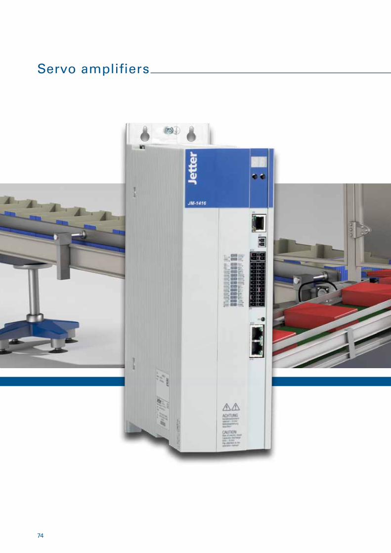
74
Servo amplifiers
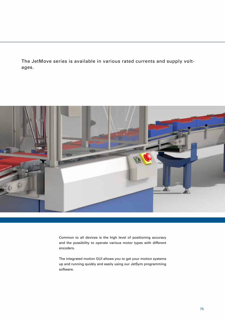
75
The JetMove series is available in various rated currents and supply volt-ages.
Common to all devices is the high level of positioning accuracy
and the possibility to operate various motor types with different
encoders.
The integrated motion GUI allows you to get your motion systems
up and running quickly and easily using our JetSym programming
software.
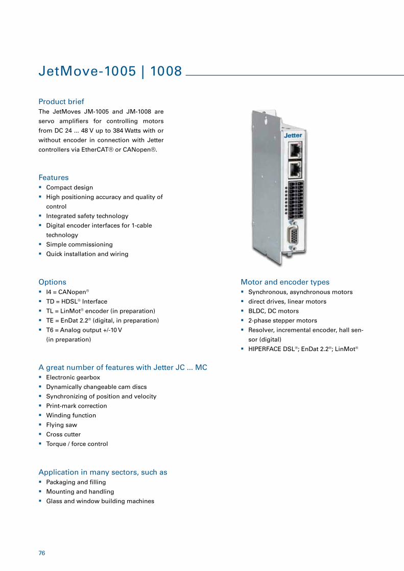
76
JetMove-1005 | 1008
Product brief
Features
Motor and encoder types
A great number of features with Jetter JC ... MC
Options
Application in many sectors, such as
The JetMoves JM-1005 and JM-1008 are
servo amplifiers for controlling motors
from DC 24 ... 48 V up to 384 Watts with or
without encoder in connection with Jetter
controllers via EtherCAT® or CANopen®.
� Compact design
� High positioning accuracy and quality of
control
� Integrated safety technology
� Digital encoder interfaces for 1-cable
technology
� Simple commissioning
� Quick installation and wiring
� Synchronous, asynchronous motors
� direct drives, linear motors
� BLDC, DC motors
� 2-phase stepper motors
� Resolver, incremental encoder, hall sen-
sor (digital)
� HIPERFACE DSL®; EnDat 2.2®; LinMot®
� Electronic gearbox
� Dynamically changeable cam discs
� Synchronizing of position and velocity
� Print-mark correction
� Winding function
� Flying saw
� Cross cutter
� Torque / force control
� I4 = CANopen®
� TD = HDSL® Interface
� TL = LinMot® encoder (in preparation)
� TE = EnDat 2.2® (digital, in preparation)
� T6 = Analog output +/-10 V
(in preparation)
� Packaging and filling
� Mounting and handling
� Glass and window building machines
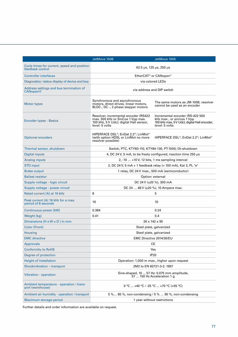
77
Further details and order information are available on request.
JetMove 1008 JetMove 1005
Cycle times for current, speed and position feedback control 62.5 µs, 125 µs, 250 µs
Controller interfaces EtherCAT® or CANopen®
Diagnostics / status display of device and bus via colored LEDs
Address settings and bus termination of CANopen® via address and DIP switch
Motor typesSynchronous and asynchronous motors, direct drives, linear motors, BLDC-, DC -, 2-phase stepper motors
The same motors as JM-1008, resolver cannot be used as an encoder
Encoder types - Basics
Resolver; incremental encoder (RS422 max. 500 kHz or SinCos 1 Vpp max. 100 kHz, 5 V Udc); digital Hall sensor, level: 5 volts
Incremental encoder (RS-422 500 kHz max., or sin/cos 1 Vpp 100 kHz max, 5 V Udc); digital Hall encoder, level: 5 volts
Optional encodersHIPERFACE DSL®; EnDat 2.2®; LinMot® (with option HDSL or LinMot no more resolver possible)
HIPERFACE DSL®; EnDat 2.2®; LinMot®
Thermal sensor, shutdown Switch, PTC, KTY83-110, KTY84-130, PT-1000; I2t-shutdown
Digital inputs 4, DC 24 V, 5 mA, to be freely configured, reaction time 250 µs
Analog inputs 2, -10 … +10 V, 12 bits, 1 ms sampling interval
STO input 2, DC 24 V, 5 mA + 1 feedback relay (< 100 mA), Kat 3, PL "e"
Brake output 1 relay, DC 24 V max., 500 mA (semiconductor)
Ballast resistor Option: external
Supply voltage - logic circuit DC 24 V (±20 %), 300 mA
Supply voltage - power circuit DC 24 … 48 V (±20 %), 10 Ampere max.
Rated current [A] at 16 kHz 8 5
Peak current [A] 16 kHz for a max. period of 8 seconds 16 10
Continuous power [kW] 0.384 0.24
Weight [kg] 0.41 0.4
Dimensions [H x W x D ] in mm 26 x 142 x 95
Color (Front) Steel plate, galvanized
Housing Steel plate, galvanized
EMC directive EMC Directive 2014/30/EU
Approvals CE
Conformity to RoHS Yes
Degree of protection IP20
Height of installation Operation: 1,000 m max., higher upon request
Shock/vibration – transport 2M2 to EN 60721-3-2: 1997
Vibration - operation Sine-shaped, 10 ... 57 Hz: 0.075 mm amplitude, 57 ... 150 Hz Acceleration 1 g
Ambient temperature - operation / trans-port (warehouse) 0 °C ... +40 °C / -25 °C ... +70 °C (+55 °C)
Ambient air humidity - operation / transport 5 %… 85 %, non-condensing / 5 % … 95 %, non-condensing
Maximum storage period 1 year without restrictions
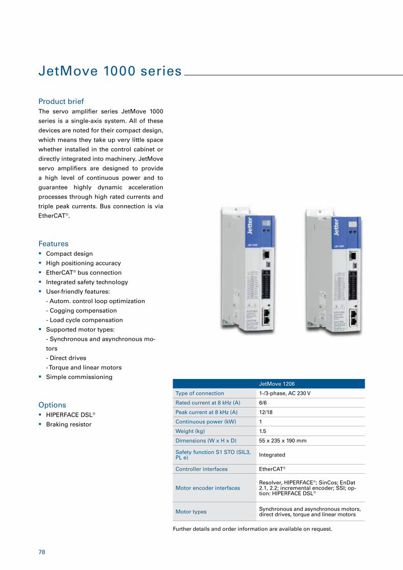
78
JetMove 1000 series
Product brief
Features
Options
The servo amplifier series JetMove 1000
series is a single-axis system. All of these
devices are noted for their compact design,
which means they take up very little space
whether installed in the control cabinet or
directly integrated into machinery. JetMove
servo amplifiers are designed to provide
a high level of continuous power and to
guarantee highly dynamic acceleration
processes through high rated currents and
triple peak currents. Bus connection is via
EtherCAT®.
� Compact design
� High positioning accuracy
� EtherCAT® bus connection
� Integrated safety technology
� User-friendly features:
- Autom. control loop optimization
- Cogging compensation
- Load cycle compensation
� Supported motor types:
- Synchronous and asynchronous mo-
tors
- Direct drives
- Torque and linear motors
� Simple commissioning
� HIPERFACE DSL®
� Braking resistor
Further details and order information are available on request.
JetMove 1206
Type of connection 1-/3-phase, AC 230 V
Rated current at 8 kHz (A) 6/6
Peak current at 8 kHz (A) 12/18
Continuous power (kW) 1
Weight (kg) 1.5
Dimensions (W x H x D) 55 x 235 x 190 mm
Safety function S1 STO (SIL3, PL e) Integrated
Controller interfaces EtherCAT®
Motor encoder interfacesResolver, HIPERFACE®; SinCos; EnDat 2.1, 2.2; incremental encoder; SSI; op-tion: HIPERFACE DSL®
Motor types Synchronous and asynchronous motors, direct drives, torque and linear motors
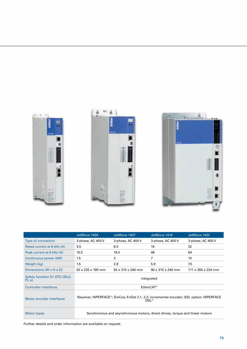
79
Further details and order information are available on request.
JetMove 1404 JetMove 1407 JetMove 1416 JetMove 1432
Type of connection 3-phase, AC 400 V 3-phase, AC 400 V 3-phase, AC 400 V 3-phase, AC 400 V
Rated current at 8 kHz (A) 3.5 6.5 16 32
Peak current at 8 kHz (A) 10.5 19.5 48 64
Continuous power (kW) 1.5 3 7 15
Weight (kg) 1.5 2.8 5.9 7.5
Dimensions (W x H x D) 55 x 235 x 190 mm 55 x 315 x 240 mm 90 x 315 x 240 mm 171 x 355 x 224 mm
Safety function S1 STO (SIL3, PL e) Integrated
Controller interfaces EtherCAT®
Motor encoder interfaces Resolver, HIPERFACE®; SinCos; EnDat 2.1, 2.2; incremental encoder; SSI; option: HIPERFACE DSL®
Motor types Synchronous and asynchronous motors, direct drives, torque and linear motors
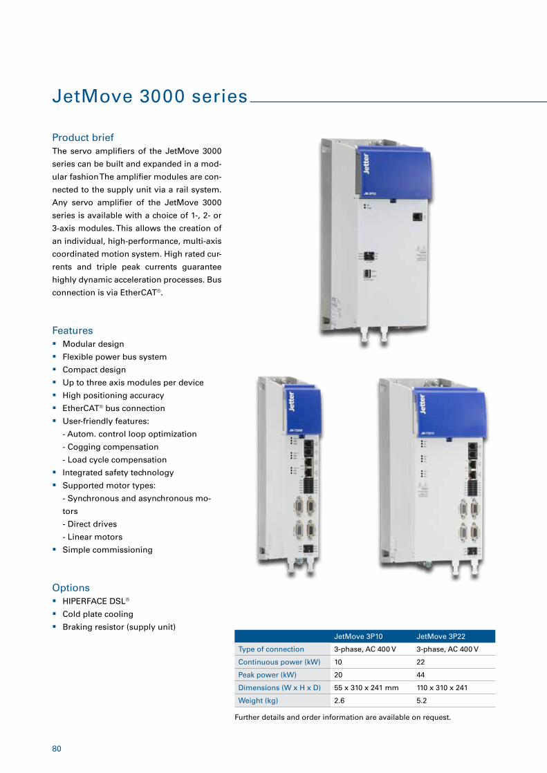
80
JetMove 3000 series
Product brief
Features
Options
The servo amplifiers of the JetMove 3000
series can be built and expanded in a mod-
ular fashion The amplifier modules are con-
nected to the supply unit via a rail system.
Any servo amplifier of the JetMove 3000
series is available with a choice of 1-, 2- or
3-axis modules. This allows the creation of
an individual, high-performance, multi-axis
coordinated motion system. High rated cur-
rents and triple peak currents guarantee
highly dynamic acceleration processes. Bus
connection is via EtherCAT®.
� Modular design
� Flexible power bus system
� Compact design
� Up to three axis modules per device
� High positioning accuracy
� EtherCAT® bus connection
� User-friendly features:
- Autom. control loop optimization
- Cogging compensation
- Load cycle compensation
� Integrated safety technology
� Supported motor types:
- Synchronous and asynchronous mo-
tors
- Direct drives
- Linear motors
� Simple commissioning
� HIPERFACE DSL®
� Cold plate cooling
� Braking resistor (supply unit)JetMove 3P10 JetMove 3P22
Type of connection 3-phase, AC 400 V 3-phase, AC 400 V
Continuous power (kW) 10 22
Peak power (kW) 20 44
Dimensions (W x H x D) 55 x 310 x 241 mm 110 x 310 x 241
Weight (kg) 2.6 5.2
Further details and order information are available on request.
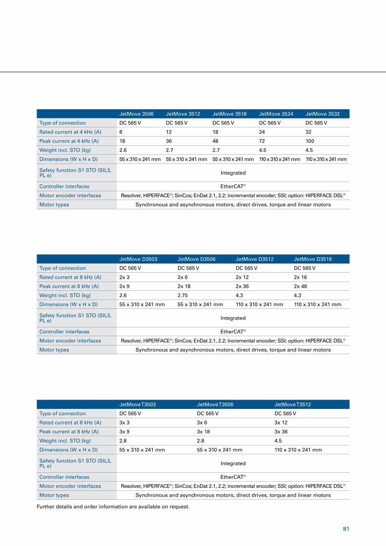
81
JetMove 3506 JetMove 3512 JetMove 3518 JetMove 3524 JetMove 3532
Type of connection DC 565 V DC 565 V DC 565 V DC 565 V DC 565 V
Rated current at 4 kHz (A) 6 12 18 24 32
Peak current at 4 kHz (A) 18 36 48 72 100
Weight incl. STO (kg) 2.6 2.7 2.7 4.5 4.5
Dimensions (W x H x D) 55 x 310 x 241 mm 55 x 310 x 241 mm 55 x 310 x 241 mm 110 x 310 x 241 mm 110 x 310 x 241 mm
Safety function S1 STO (SIL3, PL e) Integrated
Controller interfaces EtherCAT®
Motor encoder interfaces Resolver, HIPERFACE®; SinCos; EnDat 2.1, 2.2; incremental encoder; SSI; option: HIPERFACE DSL®
Motor types Synchronous and asynchronous motors, direct drives, torque and linear motors
Further details and order information are available on request.
JetMove D3503 JetMove D3506 JetMove D3512 JetMove D3516
Type of connection DC 565 V DC 565 V DC 565 V DC 565 V
Rated current at 8 kHz (A) 2x 3 2x 6 2x 12 2x 16
Peak current at 8 kHz (A) 2x 9 2x 18 2x 36 2x 48
Weight incl. STO (kg) 2.6 2.75 4.3 4.3
Dimensions (W x H x D) 55 x 310 x 241 mm 55 x 310 x 241 mm 110 x 310 x 241 mm 110 x 310 x 241 mm
Safety function S1 STO (SIL3, PL e) Integrated
Controller interfaces EtherCAT®
Motor encoder interfaces Resolver, HIPERFACE®; SinCos; EnDat 2.1, 2.2; incremental encoder; SSI; option: HIPERFACE DSL®
Motor types Synchronous and asynchronous motors, direct drives, torque and linear motors
JetMove T3503 JetMove T3506 JetMove T3512
Type of connection DC 565 V DC 565 V DC 565 V
Rated current at 8 kHz (A) 3x 3 3x 6 3x 12
Peak current at 8 kHz (A) 3x 9 3x 18 3x 36
Weight incl. STO (kg) 2.8 2.8 4.5
Dimensions (W x H x D) 55 x 310 x 241 mm 55 x 310 x 241 mm 110 x 310 x 241 mm
Safety function S1 STO (SIL3, PL e) Integrated
Controller interfaces EtherCAT®
Motor encoder interfaces Resolver, HIPERFACE®; SinCos; EnDat 2.1, 2.2; incremental encoder; SSI; option: HIPERFACE DSL®
Motor types Synchronous and asynchronous motors, direct drives, torque and linear motors
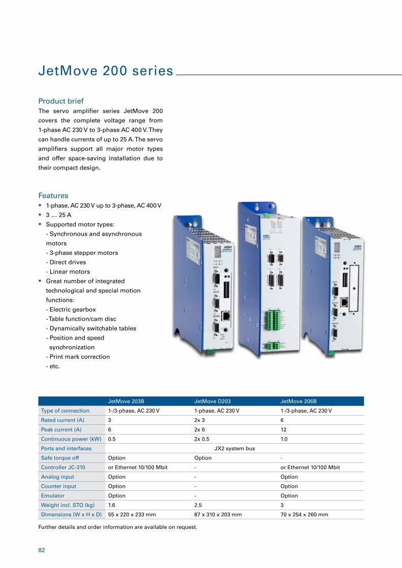
82
JetMove 200 series
Product brief
Features
The servo amplifier series JetMove 200
covers the complete voltage range from
1-phase AC 230 V to 3-phase AC 400 V. They
can handle currents of up to 25 A. The servo
amplifiers support all major motor types
and offer space-saving installation due to
their compact design.
� 1-phase, AC 230 V up to 3-phase, AC 400 V
� 3 … 25 A
� Supported motor types:
- Synchronous and asynchronous
motors
- 3-phase stepper motors
- Direct drives
- Linear motors
� Great number of integrated
technological and special motion
functions:
- Electric gearbox
- Table function/cam disc
- Dynamically switchable tables
- Position and speed
synchronization
- Print mark correction
- etc.
JetMove 203B JetMove D203 JetMove 206B
Type of connection 1-/3-phase, AC 230 V 1-phase, AC 230 V 1-/3-phase, AC 230 V
Rated current (A) 3 2x 3 6
Peak current (A) 6 2x 6 12
Continuous power (kW) 0.5 2x 0.5 1.0
Ports and interfaces JX2 system bus
Safe torque off Option Option -
Controller JC-310 or Ethernet 10/100 Mbit - or Ethernet 10/100 Mbit
Analog input Option - Option
Counter input Option - Option
Emulator Option - Option
Weight incl. STO (kg) 1.6 2.5 3
Dimensions (W x H x D) 55 x 220 x 233 mm 87 x 310 x 203 mm 70 x 254 x 260 mm
Further details and order information are available on request.
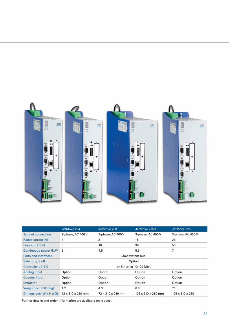
83
Further details and order information are available on request.
JetMove 204 JetMove 208 JetMove 215B JetMove 225
Type of connection 3-phase, AC 400 V 3-phase, AC 400 V 3-phase, AC 400 V 3-phase, AC 400 V
Rated current (A) 4 8 15 25
Peak current (A) 8 16 30 50
Continuous power (kW) 2 4.5 5.5 7
Ports and interfaces JX2 system bus
Safe torque off Option
Controller JC-310 or Ethernet 10/100 Mbit
Analog input Option Option Option Option
Counter input Option Option Option Option
Emulator Option Option Option Option
Weight incl. STO (kg) 4.2 4.3 6.8 7.1
Dimensions (W x H x D) 72 x 310 x 280 mm 72 x 310 x 280 mm 105 x 310 x 280 mm 105 x 310 x 280
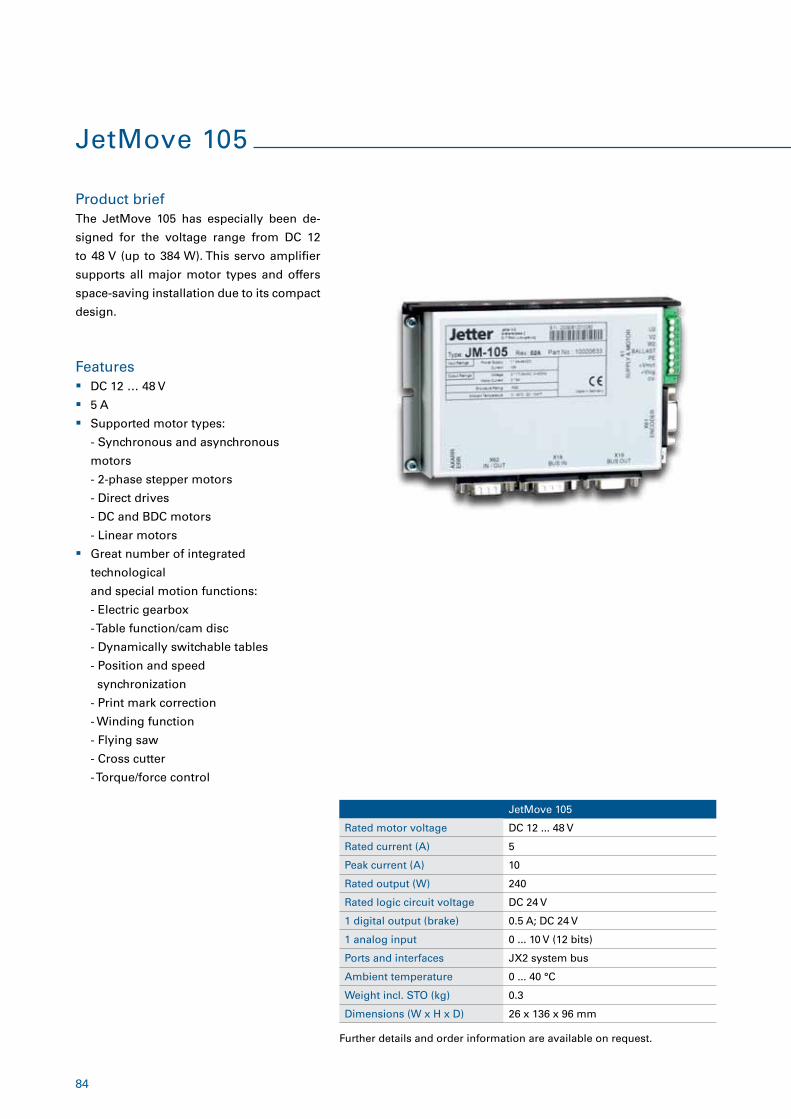
84
JetMove 105
Product brief
Features
The JetMove 105 has especially been de-
signed for the voltage range from DC 12
to 48 V (up to 384 W). This servo amplifier
supports all major motor types and offers
space-saving installation due to its compact
design.
� DC 12 … 48 V
� 5 A
� Supported motor types:
- Synchronous and asynchronous
motors
- 2-phase stepper motors
- Direct drives
- DC and BDC motors
- Linear motors
� Great number of integrated
technological
and special motion functions:
- Electric gearbox
- Table function/cam disc
- Dynamically switchable tables
- Position and speed
synchronization
- Print mark correction
- Winding function
- Flying saw
- Cross cutter
- Torque/force control
JetMove 105
Rated motor voltage DC 12 ... 48 V
Rated current (A) 5
Peak current (A) 10
Rated output (W) 240
Rated logic circuit voltage DC 24 V
1 digital output (brake) 0.5 A; DC 24 V
1 analog input 0 ... 10 V (12 bits)
Ports and interfaces JX2 system bus
Ambient temperature 0 ... 40 °C
Weight incl. STO (kg) 0.3
Dimensions (W x H x D) 26 x 136 x 96 mm
Further details and order information are available on request.
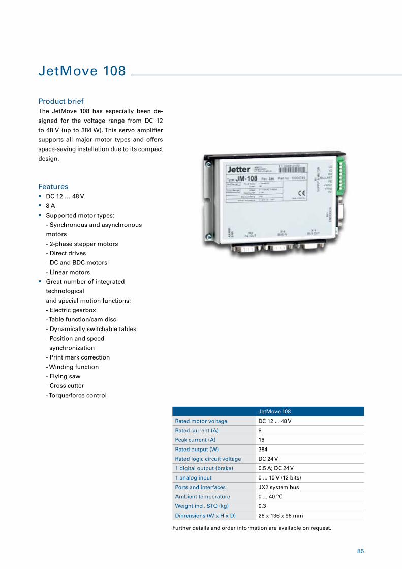
85
JetMove 108
Product brief
Features
The JetMove 108 has especially been de-
signed for the voltage range from DC 12
to 48 V (up to 384 W). This servo amplifier
supports all major motor types and offers
space-saving installation due to its compact
design.
� DC 12 … 48 V
� 8 A
� Supported motor types:
- Synchronous and asynchronous
motors
- 2-phase stepper motors
- Direct drives
- DC and BDC motors
- Linear motors
� Great number of integrated
technological
and special motion functions:
- Electric gearbox
- Table function/cam disc
- Dynamically switchable tables
- Position and speed
synchronization
- Print mark correction
- Winding function
- Flying saw
- Cross cutter
- Torque/force control
JetMove 108
Rated motor voltage DC 12 ... 48 V
Rated current (A) 8
Peak current (A) 16
Rated output (W) 384
Rated logic circuit voltage DC 24 V
1 digital output (brake) 0.5 A; DC 24 V
1 analog input 0 ... 10 V (12 bits)
Ports and interfaces JX2 system bus
Ambient temperature 0 ... 40 °C
Weight incl. STO (kg) 0.3
Dimensions (W x H x D) 26 x 136 x 96 mm
Further details and order information are available on request.
86
Motion Control eXtended - more than movement
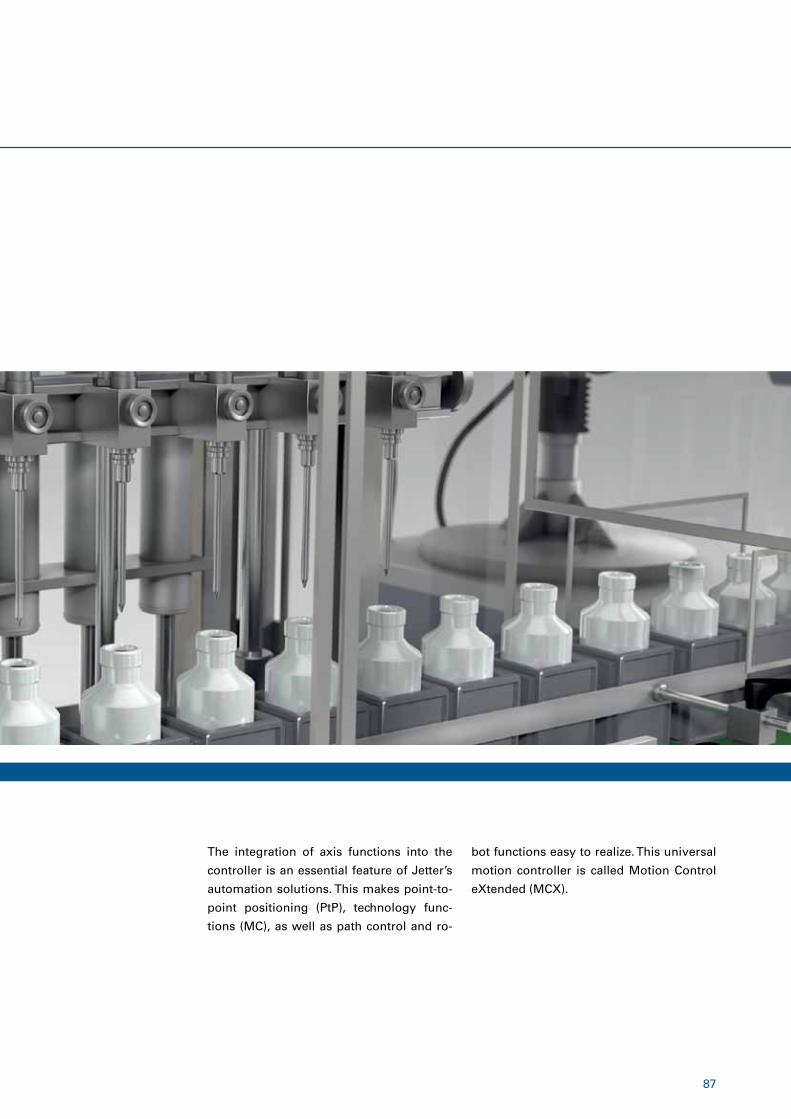
87
The integration of axis functions into the
controller is an essential feature of Jetter’s
automation solutions. This makes point-to-
point positioning (PtP), technology func-
tions (MC), as well as path control and ro-
bot functions easy to realize. This universal
motion controller is called Motion Control
eXtended (MCX).
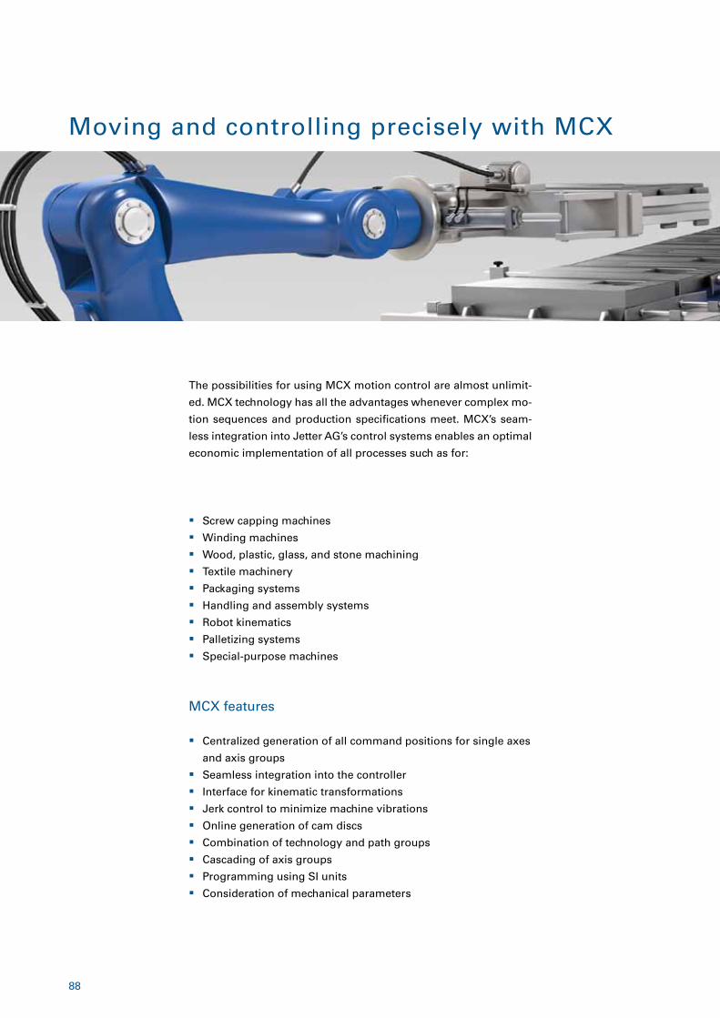
88
� Screw capping machines
� Winding machines
� Wood, plastic, glass, and stone machining
� Textile machinery
� Packaging systems
� Handling and assembly systems
� Robot kinematics
� Palletizing systems
� Special-purpose machines
MCX features
� Centralized generation of all command positions for single axes
and axis groups
� Seamless integration into the controller
� Interface for kinematic transformations
� Jerk control to minimize machine vibrations
� Online generation of cam discs
� Combination of technology and path groups
� Cascading of axis groups
� Programming using SI units
� Consideration of mechanical parameters
Moving and controlling precisely with MCX
The possibilities for using MCX motion control are almost unlimit-
ed. MCX technology has all the advantages whenever complex mo-
tion sequences and production specifications meet. MCX’s seam-
less integration into Jetter AG’s control systems enables an optimal
economic implementation of all processes such as for:
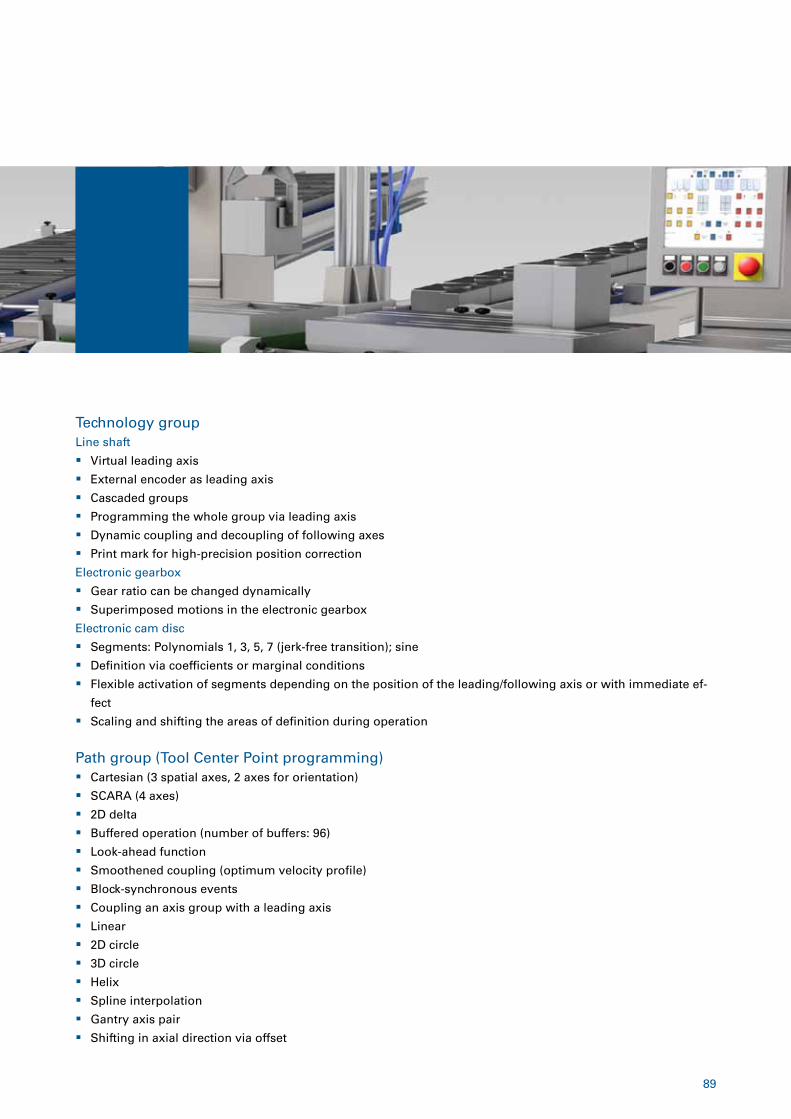
89
Technology groupLine shaft
� Virtual leading axis
� External encoder as leading axis
� Cascaded groups
� Programming the whole group via leading axis
� Dynamic coupling and decoupling of following axes
� Print mark for high-precision position correction
Electronic gearbox
� Gear ratio can be changed dynamically
� Superimposed motions in the electronic gearbox
Electronic cam disc
� Segments: Polynomials 1, 3, 5, 7 (jerk-free transition); sine
� Definition via coefficients or marginal conditions
� Flexible activation of segments depending on the position of the leading/following axis or with immediate ef-
fect
� Scaling and shifting the areas of definition during operation
Path group (Tool Center Point programming) � Cartesian (3 spatial axes, 2 axes for orientation)
� SCARA (4 axes)
� 2D delta
� Buffered operation (number of buffers: 96)
� Look-ahead function
� Smoothened coupling (optimum velocity profile)
� Block-synchronous events
� Coupling an axis group with a leading axis
� Linear
� 2D circle
� 3D circle
� Helix
� Spline interpolation
� Gantry axis pair
� Shifting in axial direction via offset
90
The MCX hardware and software package
JetControl 365MC � Up to 12 axes
� 4 path groups
� 6 technology groups
� 24 cam discs/100 segments
JetControl 440MC � Up to 12 axes
� 4 path groups
� 6 technology groups
� 24 cam discs/100 segments
JetControl 94xMC � Up to 64 axes
� 50 path groups
� 100 technology groups
� 24 cam discs/100 segments
JetControl 97xMC � Up to 64 axes
� 50 path groups
� 100 technology groups
� 24 cam discs/100 segments
� Integrated IPC with Windows OS
Servo amplifiers You will find the right servo amplifier from Page 76 of this catalog.
Servo motorsYou will find the right servo motor from Page 94 of this catalog.
You can select your JetControl controller
with MCX functionality from a scalable plat-
form. Suitable servo amplifiers of the Jet-
Move series with 250 W to 15 kW of continu-
ous power and servo motors with gearbox
round off the system perfectly.
Controllers with MCX feature
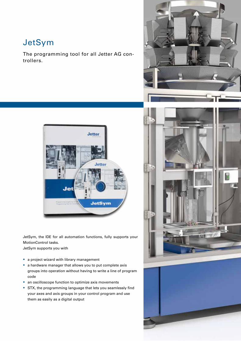
91
JetSym
JetSym, the IDE for all automation functions, fully supports your
MotionControl tasks.
JetSym supports you with
� a project wizard with library management
� a hardware manager that allows you to put complete axis
groups into operation without having to write a line of program
code
� an oscilloscope function to optimize axis movements
� STX, the programming language that lets you seamlessly find
your axes and axis groups in your control program and use
them as easily as a digital output
The programming tool for all Jetter AG con-trollers.
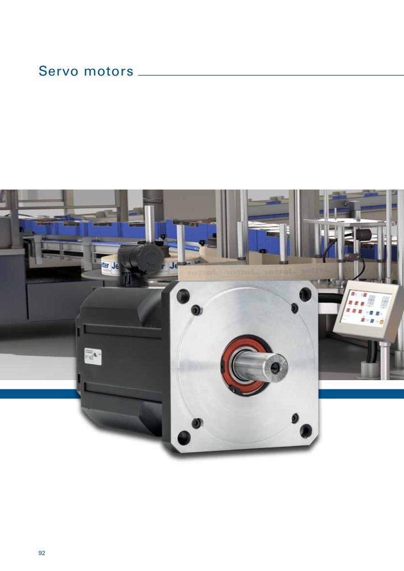
92
Servo motors
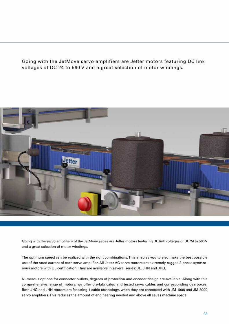
93
Going with the JetMove servo amplifiers are Jetter motors featuring DC link voltages of DC 24 to 560 V and a great selection of motor windings.
Going with the servo amplifiers of the JetMove series are Jetter motors featuring DC link voltages of DC 24 to 560 V
and a great selection of motor windings.
The optimum speed can be realized with the right combinations. This enables you to also make the best possible
use of the rated current of each servo amplifier. All Jetter AG servo motors are extremely rugged 3-phase synchro-
nous motors with UL certification. They are available in several series: JL, JHN and JHQ.
Numerous options for connector outlets, degrees of protection and encoder design are available. Along with this
comprehensive range of motors, we offer pre-fabricated and tested servo cables and corresponding gearboxes.
Both JHQ and JHN motors are featuring 1-cable technology, when they are connected with JM-1000 and JM-3000
servo amplifiers. This reduces the amount of engineering needed and above all saves machine space.
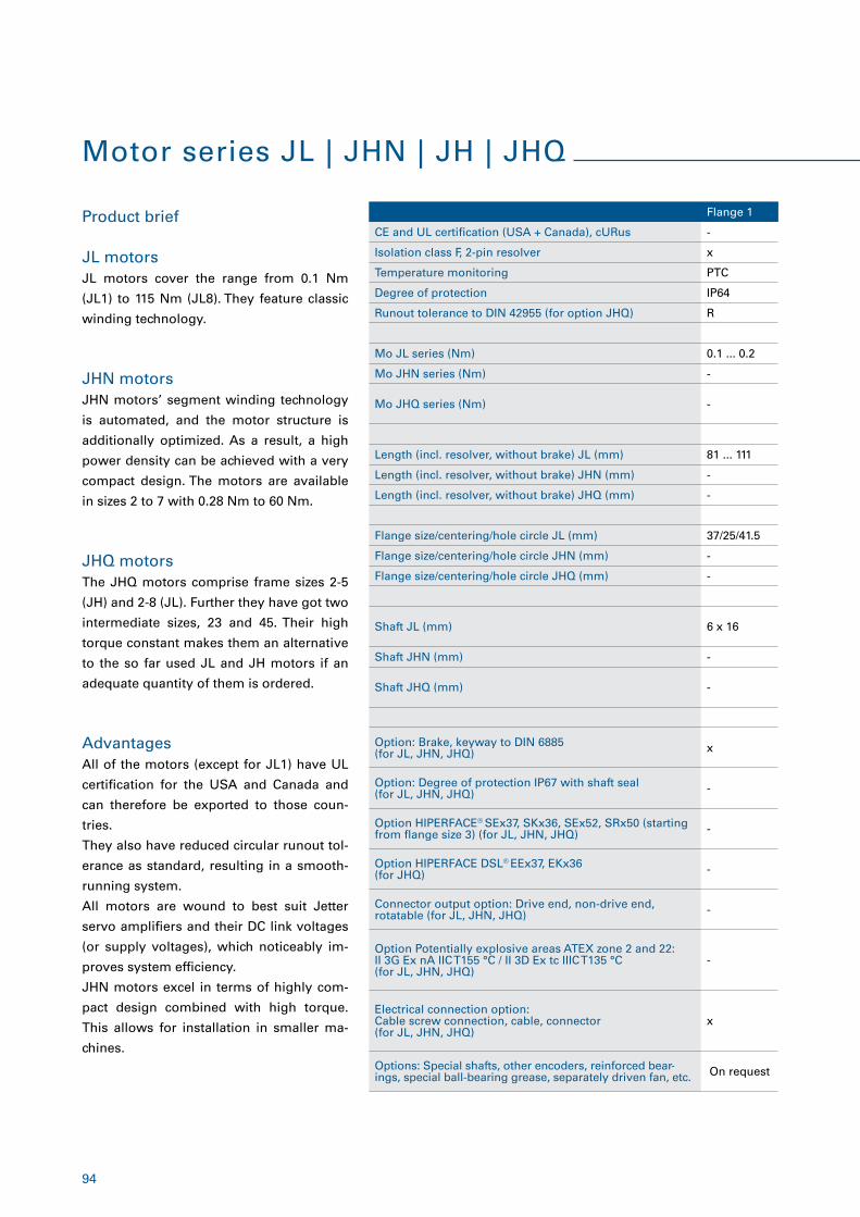
94
Motor series JL | JHN | JH | JHQ
Product brief
Advantages
JL motors cover the range from 0.1 Nm
(JL1) to 115 Nm (JL8). They feature classic
winding technology.
JHN motors’ segment winding technology
is automated, and the motor structure is
additionally optimized. As a result, a high
power density can be achieved with a very
compact design. The motors are available
in sizes 2 to 7 with 0.28 Nm to 60 Nm.
The JHQ motors comprise frame sizes 2-5
(JH) and 2-8 (JL). Further they have got two
intermediate sizes, 23 and 45. Their high
torque constant makes them an alternative
to the so far used JL and JH motors if an
adequate quantity of them is ordered.
JHQ motors
JHN motors
JL motors
All of the motors (except for JL1) have UL
certification for the USA and Canada and
can therefore be exported to those coun-
tries.
They also have reduced circular runout tol-
erance as standard, resulting in a smooth-
running system.
All motors are wound to best suit Jetter
servo amplifiers and their DC link voltages
(or supply voltages), which noticeably im-
proves system efficiency.
JHN motors excel in terms of highly com-
pact design combined with high torque.
This allows for installation in smaller ma-
chines.
Flange 1
CE and UL certification (USA + Canada), cURus -
Isolation class F, 2-pin resolver x
Temperature monitoring PTC
Degree of protection IP64
Runout tolerance to DIN 42955 (for option JHQ) R
Mo JL series (Nm) 0.1 ... 0.2
Mo JHN series (Nm) -
Mo JHQ series (Nm) -
Length (incl. resolver, without brake) JL (mm) 81 ... 111
Length (incl. resolver, without brake) JHN (mm) -
Length (incl. resolver, without brake) JHQ (mm) -
Flange size/centering/hole circle JL (mm) 37/25/41.5
Flange size/centering/hole circle JHN (mm) -
Flange size/centering/hole circle JHQ (mm) -
Shaft JL (mm) 6 x 16
Shaft JHN (mm) -
Shaft JHQ (mm) -
Option: Brake, keyway to DIN 6885(for JL, JHN, JHQ) x
Option: Degree of protection IP67 with shaft seal(for JL, JHN, JHQ) -
Option HIPERFACE® SEx37, SKx36, SEx52, SRx50 (starting from flange size 3) (for JL, JHN, JHQ) -
Option HIPERFACE DSL® EEx37, EKx36(for JHQ) -
Connector output option: Drive end, non-drive end, rotatable (for JL, JHN, JHQ) -
Option Potentially explosive areas ATEX zone 2 and 22: II 3G Ex nA IIC T155 °C / II 3D Ex tc IIIC T135 °C(for JL, JHN, JHQ)
-
Electrical connection option: Cable screw connection, cable, connector(for JL, JHN, JHQ)
x
Options: Special shafts, other encoders, reinforced bear-ings, special ball-bearing grease, separately driven fan, etc. On request
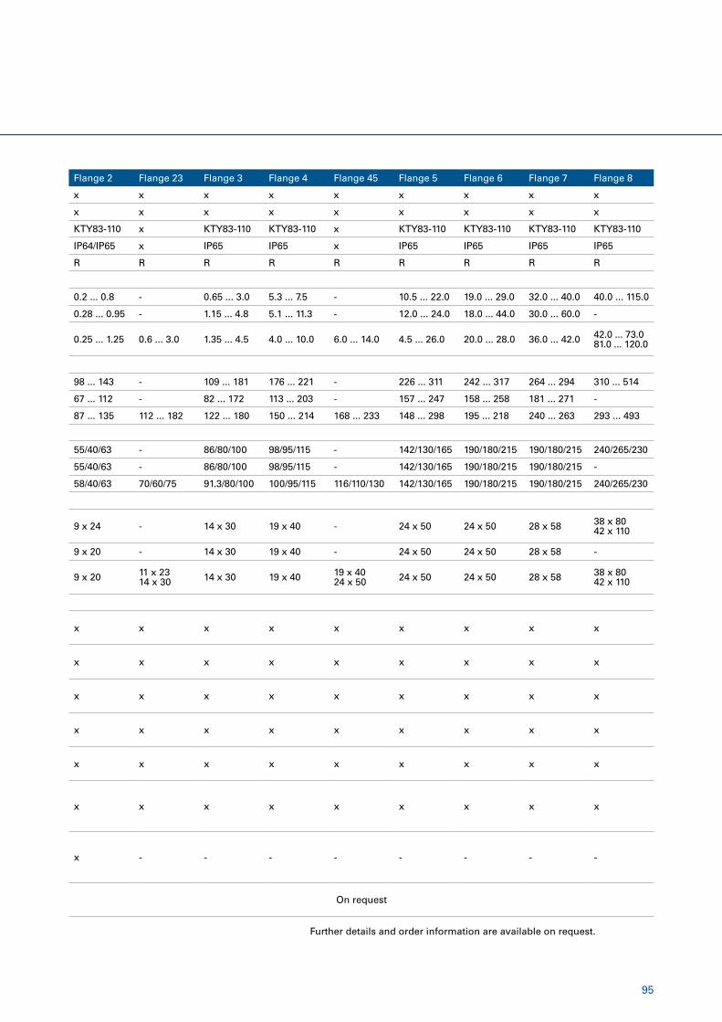
95
Flange 2 Flange 23 Flange 3 Flange 4 Flange 45 Flange 5 Flange 6 Flange 7 Flange 8
x x x x x x x x x
x x x x x x x x x
KTY83-110 x KTY83-110 KTY83-110 x KTY83-110 KTY83-110 KTY83-110 KTY83-110
IP64/IP65 x IP65 IP65 x IP65 IP65 IP65 IP65
R R R R R R R R R
0.2 ... 0.8 - 0.65 ... 3.0 5.3 ... 7.5 - 10.5 ... 22.0 19.0 ... 29.0 32.0 ... 40.0 40.0 ... 115.0
0.28 ... 0.95 - 1.15 ... 4.8 5.1 ... 11.3 - 12.0 ... 24.0 18.0 ... 44.0 30.0 ... 60.0 -
0.25 ... 1.25 0.6 ... 3.0 1.35 ... 4.5 4.0 ... 10.0 6.0 ... 14.0 4.5 ... 26.0 20.0 ... 28.0 36.0 ... 42.0 42.0 ... 73.0 81.0 ... 120.0
98 ... 143 - 109 ... 181 176 ... 221 - 226 ... 311 242 ... 317 264 ... 294 310 ... 514
67 ... 112 - 82 ... 172 113 ... 203 - 157 ... 247 158 ... 258 181 ... 271 -
87 ... 135 112 ... 182 122 ... 180 150 ... 214 168 ... 233 148 ... 298 195 ... 218 240 ... 263 293 ... 493
55/40/63 - 86/80/100 98/95/115 - 142/130/165 190/180/215 190/180/215 240/265/230
55/40/63 - 86/80/100 98/95/115 - 142/130/165 190/180/215 190/180/215 -
58/40/63 70/60/75 91.3/80/100 100/95/115 116/110/130 142/130/165 190/180/215 190/180/215 240/265/230
9 x 24 - 14 x 30 19 x 40 - 24 x 50 24 x 50 28 x 58 38 x 80 42 x 110
9 x 20 - 14 x 30 19 x 40 - 24 x 50 24 x 50 28 x 58 -
9 x 20 11 x 2314 x 30 14 x 30 19 x 40 19 x 40
24 x 50 24 x 50 24 x 50 28 x 58 38 x 8042 x 110
x x x x x x x x x
x x x x x x x x x
x x x x x x x x x
x x x x x x x x x
x x x x x x x x x
x x x x x x x x x
x - - - - - - - -
On request
Further details and order information are available on request.

96
Professional Services

97
Jetter AG provide professional services for the entire field of mechanical and plant engineering. The choice is yours: You can have us manage your entire project, or you can allow us to contribute our know-how for specific solu-tions.
Our services at a glance:
� Consulting | Project management
� Controller programming services
� Creation of visualization applications
� Electrical engineering | Control cabinet production
� Service | Maintenance
� Training
� Retrofit
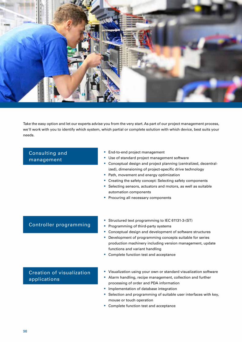
98
� End-to-end project management
� Use of standard project management software
� Conceptual design and project planning (centralized, decentral-
ized), dimensioning of project-specific drive technology
� Path, movement and energy optimization
� Creating the safety concept: Selecting safety components
� Selecting sensors, actuators and motors, as well as suitable
automation components
� Procuring all necessary components
� Structured text programming to IEC 61131-3-(ST)
� Programming of third-party systems
� Conceptual design and development of software structures
� Development of programming concepts suitable for series
production machinery including version management, update
functions and variant handling
� Complete function test and acceptance
� Visualization using your own or standard visualization software
� Alarm handling, recipe management, collection and further
processing of order and PDA information
� Implementation of database integration
� Selection and programming of suitable user interfaces with key,
mouse or touch operation
� Complete function test and acceptance
Consulting andmanagement
Take the easy option and let our experts advise you from the very start. As part of our project management process,
we'll work with you to identify which system, which partial or complete solution with which device, best suits your
needs.
Controller programming
Creation of visualization applications
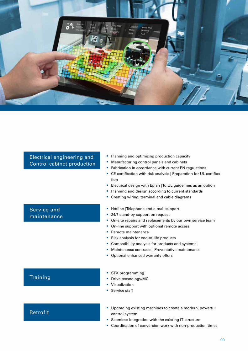
99
� Planning and optimizing production capacity
� Manufacturing control panels and cabinets
� Fabrication in accordance with current EN regulations
� CE certification with risk analysis | Preparation for UL certifica-
tion
� Electrical design with Eplan | To UL guidelines as an option
� Planning and design according to current standards
� Creating wiring, terminal and cable diagrams
� Hotline | Telephone and e-mail support
� 24/7 stand-by support on request
� On-site repairs and replacements by our own service team
� On-line support with optional remote access
� Remote maintenance
� Risk analysis for end-of-life products
� Compatibility analysis for products and systems
� Maintenance contracts | Preventative maintenance
� Optional enhanced warranty offers
� STX programming
� Drive technology/MC
� Visualization
� Service staff
� Upgrading existing machines to create a modern, powerful
control system
� Seamless integration with the existing IT structure
� Coordination of conversion work with non-production times
Service andmaintenance
Training
Retrofit
Electrical engineering andControl cabinet production
We automate your success.
Jetter AG
Graeterstrasse 2
71642 Ludwigsburg | Germany
Phone +49 7141 2550-0
Fax +49 7141 2550-425
www.jetter.de Item
# 6
0876
905
| 11/
2017


