507155-01
������������04/13
������
2013Litho U.S.A.
WARNINGImproper installation, adjustment, alteration, service or maintenance can cause property damage,personal injury or loss of life. Installation and service must be performed by a licensed professionalHVAC installer or equivalent, service agency, or thegas supplier
Table Of Contents
Dimensions Page 2. . . . . . . . . . . . . . . . . . . . . . . . . . . . . . . . .
Parts Arrangements Page 3. . . . . . . . . . . . . . . . . . . . . . . . .
Shipping and Packing List Page 4. . . . . . . . . . . . . . . . . . . .
General Page 4. . . . . . . . . . . . . . . . . . . . . . . . . . . . . . . . . . . .
Requirements Page 4. . . . . . . . . . . . . . . . . . . . . . . . . . . . . . .
Unit Support Page 5. . . . . . . . . . . . . . . . . . . . . . . . . . . . . . . .
Duct Connection Page 5. . . . . . . . . . . . . . . . . . . . . . . . . . . .
Rigging Unit For Lifting Page 5. . . . . . . . . . . . . . . . . . . . . . .
Horizontal Air Discharge Page 6. . . . . . . . . . . . . . . . . . . . . .
Condensate Drains Page 6. . . . . . . . . . . . . . . . . . . . . . . . . .
Gas Piping Page 8. . . . . . . . . . . . . . . . . . . . . . . . . . . . . . . . .
Pressure Test Gas Piping Page 9. . . . . . . . . . . . . . . . . . . . .
INSTALLATIONINSTRUCTIONS
LGH/LCH036, 048,060 & 0723, 4, 5 and 6 Ton
GAS AND COOLING PACKAGED UNITS507155-014/2013Supersedes 507085-01
High Altitude Derate Page 9. . . . . . . . . . . . . . . . . . . . . . . . .
Electrical Connections Page 9. . . . . . . . . . . . . . . . . . . . . . .
Blower Operation and Adjustments Page 12. . . . . . . . . . . .
Cooling Start-Up Page 28. . . . . . . . . . . . . . . . . . . . . . . . . . . .
Gas Heat Start-Up Page 38. . . . . . . . . . . . . . . . . . . . . . . . . . .
Heating Operation and Adjustments Page 39. . . . . . . . . . . .
Electric Heat Start-Up Page 39. . . . . . . . . . . . . . . . . . . . . . . .
Ventilation Control Board Start-Up Page 40. . . . . . . . . . . . .
Hot Gas Reheat Startup Page 42. . . . . . . . . . . . . . . . . . . . . .
Service Page 43. . . . . . . . . . . . . . . . . . . . . . . . . . . . . . . . . . . .
CAUTIONDanger of sharp metallic edges. Can cause injury.Take care when servicing unit to avoid accidentalcontact with sharp edges.
RETAIN THESE INSTRUCTIONS FOR FUTURE REFERENCE
LG SHOWN
LLENOXN
LENOXN
LENOXN

Page 2
LGH/LCH036, 048, 060, 072
LGH/LCH036, 048, 060, & 072 DIMENSIONS in. - Gas heat section shown
45(1143)
END VIEW
1 (25)
47 (1192)BASE
38−
7/8
(987
) 03
6 th
ru 0
4846
−7/
8 (1
191)
060
thru
072
DD CC
BBAA
FF
EE
11(279)
16−1/4(413)
18(457)
20(508)
5 (102)
47 (1192)BASE
BOTTOMSUPPLY
AIROPENING
TOP VIEW (Base)
CENTEROF
GRAVITY
9−1/2(241)6−5/8
(168)
26−1/2(673)
5−5/8(143)
29(737)
7 (178) BOTTOMRETURN
AIROPENING
BOTTOMCONDENSATE OUTLET
25−3/4(654)
BOTTOM POWER ENTRY3 X 8 (76 X 203)
18−3/8(467)
19−1/2(495)
5−1/2(140)
FORKLIFT SLOTS(Front, Back and
Blower End)
HORIZONTALRETURN AIR
OPENING(Without Economizer)
HORIZONTALSUPPLY AIR
OPENING
2 (51)11
(279)
29(737)
20(508)
5−1/2(140)
BACK VIEW
CONDENSATEOUTLET
(EITHER SIDE)
3−1/2 (89)
83−1/4(2115)
85−1/4 (2165)BASE
26−1/2(673)
5−1/2(140)
GASINLET
FLUE/VENTOUTLET
LIFTING HOLES(For rigging)
SIDE VIEW
27(686)
15 (381)
ELECTRICALINLET
1 (25)35−
3/8
(899
) 03
6 th
ru 0
4843
−3/
8 (1
102)
060
thru
072
85−1/4 (2165)BASE
85−1/4 (2165)BASE
38−
7/8
(987
) 03
6 th
ru 0
4846
−7/
8 (1
191)
060
thru
072

Page 3
LGH/LCH036, 048, 060, 072
LGH036, 048, 060, & 072 PARTS ARRANGEMENT
LLENOXN
LENOXN
LENOXN
EVAPORATORCOIL
CONDENSERFAN
CONDENSERCOIL
COMPRESSOR
CONDENSATEDRAIN
FILTERS (4)
036, 048:16 X 20 X 2”060, 072: 20 X 20 X 2”
ECONOMIZER(OPTIONAL)
GAS VALVEBURNERS
COMBUSTIONAIR INDUCER
BLOWERMOTOR
(DIRECT DRIVE SHOWN)
TXV
UNITCONTROLLER
REHEAD COIL(OPTIONAL)
BLOWER COILGUARDS
(OPTIONAL)
LCH036, 048, 060, & 072 PARTS ARRANGEMENT
LLENOXN
LENOXN
LENOXN
ELECTRIC HEAT(Optional)
EVAPORATORCOIL
CONDENSERFAN
CONDENSERCOIL
COMPRESSOR
CONDENSATEDRAIN
ECONOMIZER(OPTIONAL)
BLOWER
BLOWERMOTOR
(BELT DRIVE SHOWN)
FILTERS (4)
036, 048:16 X 20 X 2”060, 072: 20 X 20 X 2”
TXV
UNITCONTROLLER
REHEAT COIL(OPTIONAL)
Page 4
LGH/LCH036, 048, 060, 072
Shipping and Packing List
Package 1 of 1 contains:
1- Assembled unit
Check unit for shipping damage. Receiving party should
contact last carrier immediately if shipping damage is found.
General
These instructions are intended as a general guide
and do not supersede local codes in any way.
Authorities having jurisdiction should be consulted
before installation.
The LGH units are available in three heating inputs. The
LCH cooling packaged rooftop unit is the same basic
design as the LGH unit except for the heating section.
Optional electric heat is available for LCH units. LGH and
LCH units have identical refrigerant circuits with
respective 3, 4, 5, and 6 ton cooling capacities.
Units come standard with a lightweight, all-aluminum
condenser coil. Units are also available with an optional
fin/tube condenser coil.
In addition to standard heating and cooling, hot gas
reheat units provide a dehumidifying mode of operation.
Refer to Reheat Operation section.
An optional factory-installed ventilation control board
(VCB) is available. Units equipped with a VCB allow the
installer to enter the design-specified supply air and
outdoor air CFM into the Unit Controller. See VCB
Start-Up section.
Availability of units and options varies by brand.
Requirements
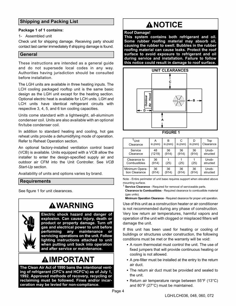
See figure 1 for unit clearances.
WARNINGElectric shock hazard and danger ofexplosion. Can cause injury, death orproduct or property damage. Turn offgas and electrical power to unit beforeperforming any maintenance orservicing operations on the unit. Followlighting instructions attached to unitwhen putting unit back into operationand after service or maintenance.
IMPORTANTThe Clean Air Act of 1990 bans the intentional venting of refrigerant (CFC's and HCFC's) as of July 1,1992. Approved methods of recovery, recycling orreclaiming must be followed. Fines and/or incarceration may be levied for non-compliance.
NOTICERoof Damage!This system contains both refrigerant and oil.Some rubber roofing material may absorb oil,causing the rubber to swell. Bubbles in the rubberroofing material can cause leaks. Protect the roofsurface to avoid exposure to refrigerant and oilduring service and installation. Failure to followthis notice could result in damage to roof surface.
UNIT CLEARANCES
C
D
B
A
FIGURE 1
1Unit
Clearance
Ain.(mm)
Bin.(mm)
Cin.(mm)
Din.(mm)
TopClearance
ServiceClearance
48(1219)
36(914)
36(914)
36(914)
Unobstructed
Clearance toCombustibles
36(914)
1(25)
1(25)
1(25)
Unobstructed
Minimum Operation Clearance
36(914)
36(914)
36(914)
36(914)
Unobstructed
Note - Entire perimeter of unit base requires support when elevated above
mounting surface.
1 Service Clearance - Required for removal of serviceable parts.
Clearance to Combustibles - Required clearance to combustible material
(gas units).
Minimum Operation Clearance - Required clearance for proper unit operation.
Use of this unit as a construction heater or air conditioner
is not recommended during any phase of construction.
Very low return air temperatures, harmful vapors and
operation of the unit with clogged or misplaced filters will
damage the unit.
If this unit has been used for heating or cooling of
buildings or structures under construction, the following
conditions must be met or the warranty will be void:
� A room thermostat must control the unit. The use of
fixed jumpers that will provide continuous heating or
cooling is not allowed.
� A pre-filter must be installed at the entry to the return
air duct.
� The return air duct must be provided and sealed to
the unit.
� Return air temperature range between 55°F (13°C)
and 80°F (27°C) must be maintained.
Page 5
LGH/LCH036, 048, 060, 072
� Air filters must be replaced and pre-filters must be
removed upon construction completion.
� The input rate and temperature rise must be set per
the unit rating plate.
� The heat exchanger, components, duct system, air
filters and evaporator coil must be thoroughly
cleaned following final construction clean-up.
� The unit operating conditions (including airflow,
cooling operation, ignition, input rate, temperature
rise and venting) must be verified according to these
installation instructions.
Unit Support
In downflow discharge installations, install the unit on a
non-combustible surface only. Unit may be installed on
combustible surfaces when used in horizontal discharge
applications or in downflow discharge applications when
installed on an T1CURB / C1CURB / E1CURB roof
mounting frame.
NOTE - Securely fasten roof frame to roof per local codes.
A-Downflow Discharge Application
Roof Mounting with T1CURB / C1CURB / E1CURB
1- The roof mounting frame must be installed, flashed
and sealed in accordance with the instructions
provided with the frame.
2- The roof mounting frame should be square and level
to 1/16” per linear foot (5mm per linear meter) in any
direction.
3- Duct must be attached to the roof mounting frame
and not to the unit; supply and return plenums must
be installed before setting the unit.
Installer's Roof Mounting Frame
Many types of roof frames can be used to install the unit
depending upon different roof structures. Items to keep
in mind when using the building frame or supports are:
1- The base is fully enclosed and insulated, so an
enclosed frame is not required.
2- The frames or supports must be constructed with
non-combustible materials and should be square and
level to 1/16” per linear foot (5mm per linear meter)
in any direction.
3- Frame or supports must be high enough to prevent
any form of moisture from entering unit.
Recommended minimum frame height is 14”
(356mm).
4- Duct must be attached to the roof mounting frame
and not to the unit. Supply and return plenums must
be installed before setting the unit.
5- Units require support along all four sides of unit base.
Supports must be constructed of steel or suitably
treated wood materials.
NOTE-When installing a unit on a combustible surface for
downflow discharge applications, a T1CURB / C1CURB /
E1CURB roof mounting frame is required.
B-Horizontal Discharge Applications
1- Units which are equipped with an optional
economizer and installed in horizontal airflow
applications must use a horizontal conversion kit.
2- Specified installation clearances must be maintained
when installing units. Refer to figure 1.
3- Top of support slab should be approximately 4”
(102mm) above the finished grade and located so no
run-off water from higher ground can collect around
the unit.
4- Units require support along all four sides of unit base.
Supports must be constructed of steel or suitably
treated wood materials.
Duct Connection
All exterior ducts, joints and openings in roof or building
walls must be insulated and weather-proofed with
flashing and sealing compounds in accordance with
applicable codes. Any duct passing through an
unconditioned space must be insulated.
CAUTIONIn downflow applications, do not drill or punchholes in base of unit. Leaking in roof may occur ifunit base is punctured.
Rigging Unit For Lifting
Rig unit for lifting by attaching four cables to holes in unit
base rail. See figure 2.
1- Detach wooden base protection before rigging.
2- Remove all six base protection brackets before
setting unit.
3- Connect rigging to the unit base using both holes in
each corner.
4- All panels must be in place for rigging.
5- Place field‐provided H‐style pick in place just above
top edge of unit. Frame must be of adequate
strength and length. (H-style pick prevents damage
to unit.)

Page 6
LGH/LCH036, 048, 060, 072
LG
LC
FIGURE 2
IMPORTANT - ALLPANELS MUSTBE IN PLACE
FOR RIGGING.
LIFTING POINT SHOULDBE DIRECTLY ABOVECENTER OF GRAVITY
*Maximum weight with all availablefactory-installed accessories.
435
423
Unit*Weight
Lbs. Kg.
CAUTION - Donot walk on unit.
960
933
Horizontal Air Discharge
Unit is shipped with panels covering the horizontal supply
and return air openings. Remove horizontal covers and
place over downflow openings for horizontal air discharge.
See figure 3. Secure in place with sheet metal screws.
Units Equipped With An Optional Economizer
1- Remove the horizontal supply air cover and position
over the downflow supply air opening. Secure with
sheet metal screws.
2- Leave the horizontal return air cover in place.
3- Locate the separately ordered horizontal air
discharge kit. Place the kit panel over the downflow
return air opening.
4- Remove and retain the barometric relief dampers and
lower hood.
FIGURE 3
DOWNFLOWRETURN AIR
OPENING
UNIT SUPPLY AND RETURN AIR OPENINGS
DOWNFLOWSUPPLY AIR
OPENING
HORIZONTALRETURN AIR
OPENING
HORIZONTALSUPPLY AIR
OPENING
5- Install return air duct beneath outdoor air intake. See
figure 4. Install barometric relief damper in lower
hood and install in ductwork as shown in figure 4.
FIGURE 4
HORIZONTAL RETURN AIR DUCTWORKWITH ECONOMIZER
HORIZONTALRETURN AIR
DUCT
INSTALL BAROMETRIC RELIEF DAMPERSAND HOOD IN RETURN AIR DUCT
UNITUNIT
Condensate Drains
Make drain connection to the drain coupling provided on
unit. Older model units have a 3/4” N.P.T. coupling and
newer model units have a 1” N.P.T. coupling.
Note - The drain pan is made with a glass reinforced
engineered plastic capable of withstanding typical joint
torque but can be damaged with excessive force. Tighten
pipe nipple hand tight and turn an additional quarter turn.
A trap must be installed between drain connection and an
open vent for proper condensate removal. See figure 5 or
6. It is sometimes acceptable to drain condensate onto
the roof or grade; however, a tee should be fitted to the
trap to direct condensate downward. The condensate line
must be vented. Check local codes concerning
condensate disposal. Refer to pages 1 and 2 for
condensate drain location.
FIGURE 5
ÁÁÁÁÁÁÁÁÁÁÁÁÁÁÁ
UNIT
Minimum Pitch
1” (25 mm) per
10' (3 m) of line
MOUNTINGFRAME
OPEN VENT
CONDENSATE SIDE DRAIN CONNECTION
NOTE - Allow clearance toopen doors when installingcondensate piping.
CAULK AROUND CONDENSATE COUPLING
Page 7
LGH/LCH036, 048, 060, 072
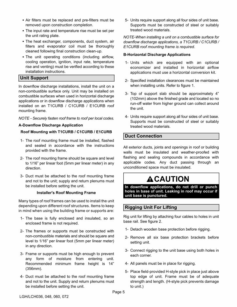
FIGURE 6
UNIT
Minimum Pitch1” (25 mm) per 10'
(3 m) of line
MOUNTINGFRAME
CONDENSATE BOTTOM DRAIN CONNECTION
OPEN VENT
CAULK AROUND
CONDENSATE COUPLING
DRAIN PAN
Units are shipped with the drain coupling facing the front
of the unit. Condensate can be drained from the back or
bottom of the unit with the following modifications. The
unit can be installed in either downflow or horizontal air
discharge regardless of condensate drain location.
Rear Drain Connection
1- Remove the condensate drain mullion. See figure 7.
Remove the two panels on each side of the mullion.
FIGURE 7
CONDENSATEDRAIN MULLION
Two hinge screws must be removed in addition to the
mullion screws. See figure 8.
FIGURE 8
CONDENSATEDRAIN MULLION
REMOVETWO
SCREWS
UNITS WITH HINGED PANELS
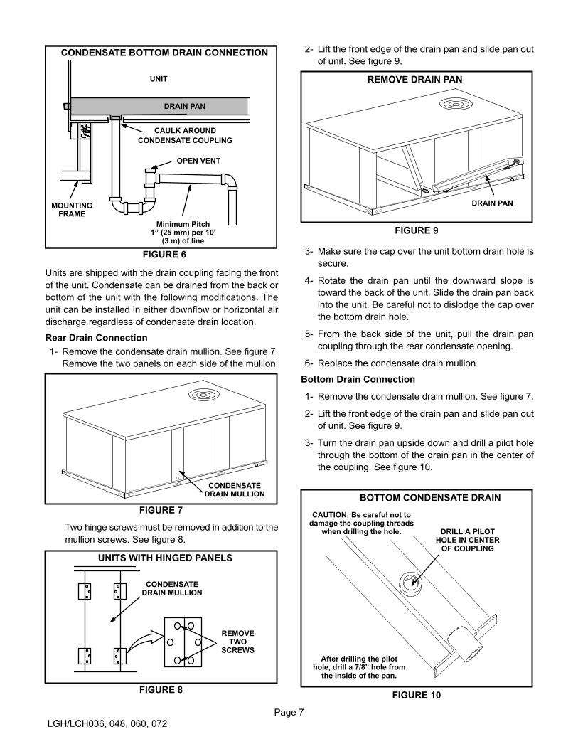
2- Lift the front edge of the drain pan and slide pan out
of unit. See figure 9.
FIGURE 9
REMOVE DRAIN PAN
DRAIN PAN
3- Make sure the cap over the unit bottom drain hole is
secure.
4- Rotate the drain pan until the downward slope is
toward the back of the unit. Slide the drain pan back
into the unit. Be careful not to dislodge the cap over
the bottom drain hole.
5- From the back side of the unit, pull the drain pan
coupling through the rear condensate opening.
6- Replace the condensate drain mullion.
Bottom Drain Connection
1- Remove the condensate drain mullion. See figure 7.
2- Lift the front edge of the drain pan and slide pan out
of unit. See figure 9.
3- Turn the drain pan upside down and drill a pilot hole
through the bottom of the drain pan in the center of
the coupling. See figure 10.
FIGURE 10
BOTTOM CONDENSATE DRAIN
DRILL A PILOTHOLE IN CENTER
OF COUPLING
After drilling the pilothole, drill a 7/8” hole from
the inside of the pan.
CAUTION: Be careful not todamage the coupling threads
when drilling the hole.

Page 8
LGH/LCH036, 048, 060, 072
4- From the inside of the pan, use a Vari-Bit® bit to
enlarge the hole to 7/8”. Do not damage coupling
threads.
5- Remove the cap over the unit bottom drain hole.
6- Slide the drain pan back into the unit.
7- From the back side of the unit, pull the drain pan
coupling through the rear condensate opening.
8- From the front side of the unit, move the drain pan
until the bottom coupling settles into the unit bottom
drain opening. Once in place, check to make sure the
coupling is still positioned through the rear
condensate drain hole.
9- Use a field-provided 3/4” plug to seal side drain
connection.
10- Replace the condensate drain mullion.
Connect Gas Piping (Gas Units)
Before connecting field-provided piping, check with gas
company or authorities having jurisdiction for local code
requirements. When installing gas supply piping, length
of run from gas meter must be considered in determining
pipe size for 0.5” w.c. (.12kPa) maximum pressure drop.
Do not use supply pipe smaller than unit gas connection.
Operating pressures at the unit gas connection must be
as shown in table 1.
TABLE 1OPERATING PRESSURE AT GAS CONNECTION “w.c.
Natural Gas LP / Propane Gas
Min. Max. Min. Max.
036-072 4.5 10.5 11 13
When making piping connections a drip leg should be
installed on vertical pipe runs to serve as a trap for
sediment or condensate. A 1/8” N.P.T. plugged tap is
located on gas valve for test gauge connection. Refer to
Heating Start-Up section for tap location. Install a ground
joint union between the gas control manifold and the
main manual shut-off valve. See figure 11 for gas supply
piping entering outside the unit. Figure 12 shows
complete bottom gas entry piping.
Compounds used on threaded joints of gas piping shall be
resistant to the action of liquified petroleum gases.
Do not use Teflon® tape to seal gas piping. Use a
moderate amount of pipe compound on the gas pipe only.
Make sure the two end threads are bare.
CAUTION
If a flexible gas connector is required or allowed bythe authority that has jurisdiction, black iron pipeshall be installed at the gas valve and extend outside the furnace cabinet.
WARNING
Do not exceed 600 in-lbs (50 ft.-lbs) torque when attaching the gas piping to the gas valve.
IMPORTANT
Compounds used on threaded joints of gas pipingmust be resistant to the actions of liquified petroleum gases.
FIGURE 11
TO GASSUPPLY
MANUAL MAIN
SHUT-OFF VALVE
GAS PIPING
SUPPORT
GROUND
JOINT UNION
(REFER TO
LOCAL CODES)
DRIP LEG
OUTSIDE OF UNIT GAS PIPE CONNECTION
TO GASVALVE

Page 9
LGH/LCH036, 048, 060, 072
DRIP LEG
MANUAL MAIN
SHUT-OFF VALVE
GROUND
JOINT UNION
FIGURE 12
BOTTOM ENTRY GAS PIPING COMPLETED
7” NIPPLE
STREETELBOW
TO GASSUPPLY
TO GASVALVE
Grommets for both gas pipe openings are field provided.
2-1/2” NIPPLE
Pressure Test Gas Piping (Gas Units)
When pressure testing gas lines, the gas valve must
be disconnected and isolated. Gas valves can be
damaged if subjected to more than 0.5 psig (3.48kPa).
See figure 13.
NOTE-Codes may require that manual main shut-off
valve and union (furnished by installer) be installed in
gas line external to unit. Union must be of the ground
joint type.
After all connections have been made, check all piping
connections for gas leaks. Also check existing unit gas
connections up to the gas valve; loosening may occur
during installation. Use a leak detection solution or other
preferred means. Do not use matches candles or other
sources of ignition to check for gas leaks.
CAUTIONSome soaps used for leak detection are corrosiveto certain metals. Carefully rinse piping thoroughlyafter leak test has been completed. Do not usematches, candles, flame or othe sources of ignitionto check for gas leaks.
WARNINGDanger of explosion. Can cause injuryor product or property damage. Do notuse matches, candles, flame or othersources of ignition to check for leaks.
NOTE-In case emergency shut down is required, turn off
the main manual shut-off valve and disconnect main
power to unit. These devices should be properly labeled
by the installer.
GAS VALVE CAP
MANUAL MAIN
SHUT-OFF VALVE
FIGURE 13
PRESSURE TEST GAS LINE
High Altitude Derate
Locate the high altitude conversion sticker in the unit
literature bag. Fill out the conversion sticker and affix next
to the unit nameplate.
Refer to table 2 for high altitude adjustments.
TABLE 2HIGH ALTITUDE DERATE
Altitude Ft.* Gas Manifold Pressure
2000-4500 See Unit Nameplate
4500 And Above Derate 2% / 1000 Ft. Above Sea Level
*Units installed at 0-2000 feet do not need to be modified.
NOTE ‐ This is the only permissible derate for these units.
Electrical Connections
POWER SUPPLY
Do not apply power or close disconnect switch until
installation is complete. Refer to start-up directions.
Refer closely to unit wiring diagram.
Refer to unit nameplate for minimum circuit ampacity
and maximum fuse size.
1- Units are factory-wired for 230,460,575 volt supply.
For 208V supply, remove the insulated terminal
cover from the 208V terminal on the control
transformer. Move the wire from the transformer
240V terminal to the 208V terminal. Place the
insulated terminal cover on the unused 240V
terminal.
2- Route power through the bottom power entry area
and connect to L1, L2, and L3 on the top of K1 in
control area above compressor. Secure power
wiring with factory-installed wire ties provided in

Page 10
LGH/LCH036, 048, 060, 072
control box. Route power to TB2 on units equipped
with electric heat. Route power to S48 or CB10 If
unit is equipped with the optional disconnect
switch or circuit breaker. See unit wiring diagram.
3- Solar-Ready Units Only -
All solar-ready units are equipped with an S48 circuit
breaker and F54 solar fuse block. Connect power
wiring to the top of S48. Connect solar module wiring
to the pigtails provided on the bottom of F54. Solar
equipment must be specified for use with this unit.
CONTROL WIRING
CAUTIONElectrostatic discharge can affect electronic components. Take precautions during unit installationand service to protect the electronic controls. Precautions will help to avoid control exposure to electrostatic discharge by putting the unit, the controland the technician at the same electrostatic potential. Neutralize electrostatic charge by touchinghands and all tools on an unpainted unit surface,such as the gas valve or blower deck, before performing any service procedure.
A-Thermostat Location
Room thermostat mounts vertically on a standard 2” X 4”
handy box or on any non-conductive flat surface.
Locate thermostat approximately 5 feet (1524mm)
above the floor in an area with good air circulation at
average temperature. Avoid locating the room
thermostat where it might be affected by:
-drafts or dead spots behind doors and in corners
-hot or cold air from ducts
-radiant heat from sun or appliances
-concealed pipes and chimneys
B-Control Wiring
The Unit Controller will operate the unit from a
thermostat or zone sensor based on the System Mode.
The default System Mode is the thermostat mode. Refer
to the Unit Controller Installation and Setup Guide to
change the System Mode. Use the menu navigation
arrows and select button; see Settings - Install.
Thermostat Mode
1- Route thermostat cable or wires from subbase to
control area above compressor (refer to unit
dimensions to locate bottom and side power entry).
IMPORTANT - Unless field thermostat wires are rated
for maximum unit voltage, they must be routed away
from line voltage wiring. Use wire ties located near the
lower left corner of the controls hat section to secure
thermostat cable.
Use18 AWG wire for all applications using remotely
installed electro-mechanical and electronic
thermostats.
2- Install thermostat assembly in accordance with
instructions provided with thermostat.
3- Connect thermostat wiring to Unit Controller on the
lower side of the controls hat section.
4- Wire as shown in figure 14 for electro-mechanical
and electronic thermostats. If using other
temperature control devices or energy management
systems see instructions and wiring diagram
provided by manufacturer.
IMPORTANT-Terminal connections at the wall plate or
subbase must be made securely. Loose control wire
connections may allow unit to operate but not with proper
response to room demand.
Zone Sensor Mode
The Unit Controller will operate heating and cooling
based on the Unit Controller internal setpoints and the
temperature from the A2 zone sensor. An optional
Network Control Panel (NCP) can also be used to provide
setpoints. A thermostat or return air sensor can be used
as a back-up mode. Make zone sensor wiring
connections as shown in figure 15.

Page 11
LGH/LCH036, 048, 060, 072
FIGURE 14
FIELD WIRING WITH ELECTRONIC AND ELECTRO-MECHANICAL THERMOSTATS(Thermostat Mode)
K55
B
A
K55−17
5
2
S86
J262
C
10
11
12
P297J297A1
2B
3
4
5
6
7
8C
9
10
R
OCP
C
G
W1
W2
Y1
Y2
24 V POWER
W1
W2
P26
2
A55R
OCP
C
G
W1
W2
Y1
Y2
TO R
TO G
TO Y1
TO PROVIDE SUPERMARKET REHEAT SCHEMEUSE S86 DEHUMIDISTAT AND K55.
ALL OTHER THERMOSTATSIGNALS REMAIN CONNECTEDAS SHOWN ON THE RIGHT.
TO M2 THERMOSTAT INPUTS
2
2
FIGURE 15
FIELD WIRING IN ZONE SENSOR MODE(Zone Sensor Mode)
A2 SENSOR
OUTPUTSSENSOR
SENSOR24VAC
R C
IAQ
HUMAI1 D01TMP D02
UNIT CONTROLLER
J298
C-Hot Gas Reheat Units Only -
1- Install humidity sensor in accordance with
instructions provided with sensor. A DDC input may
be used to initiate dehumidification instead of a
sensor.
2- Make wiring connections as shown in figure 14 for
Thermostat Mode or figure 15 for Zone Sensor
Mode. In addition, connect either a humidity
sensor or a dehumidification input. See figure 16
or 17 for humidity sensor wiring or figure 18 for
dehumidification input wiring.
Humidity Sensor Cable Applications:
Wire runs of 50 feet (mm) or less:
Use two separate shielded cables containing 20AWG
minimum, twisted pair conductors with overall shield.
Belden type 8762 or 88760 (plenum) or equivalent.
Connect both cable shield drain wires to TB1-7 as shown
in figure 16.
Wire runs of 150 feet (mm) or less:
Use two separate shielded cables containing 18AWG
minimum, twisted pair conductors with overall shield.
Belden type 8760 or 88760 (plenum) or equivalent.
Connect both cable shield drain wires to TB1-7 as shown
in figure 16.
Wire runs over 150 feet (mm):
Use a local, isolated 24VAC transformer such as Lennox
cat #18M13 (20VA minimum) to supply power to RH
sensor as shown in figure 17. Use two shielded cables
containing 20AWG minimum, twisted pair conductors
with overall shield. Belden type 8762 or 88760 (plenum)
or equivalent.

Page 12
LGH/LCH036, 048, 060, 072
FIGURE 16
FIELD WIRING REHEAT UNITS (Using A HumiditySensor With Less Than 150 Ft. Wire Runs)
9
8
10
11
122
J262
B
5
P298J298A
6
1
2B
3
4C
5
6
7D
10
A91
VIN
VO
GND
P26
2
R
C
AI−1
HUM
TMP
DO−1
C
DI−1
DO−2
FIGURE 17
FIELD WIRING REHEAT UNITS (Using A HumiditySensor With More than 150 Ft. Wire Runs)
ISOLATED 24V
TRANSFORMER
9
8
P298J298A1
2B
3
4C
5
6
7D
10
A91
VIN
VO
GND
R
C
AI-1
HUM
TMP
DO-1
C
DI-1
DO-2
NOT
CONNECTED
NOTCONNECTED
DRAIN
A55 UNITCONTROLLER
FIGURE 18
FIELD WIRING REHEAT UNITS(Using A Dehumidification Switch)
7
10
8
9
R
DI−4
C
Use 24 VAC (R) from any terminalavailable on J299−2, −5, or −7.
J299
DEHUMIDIFICATIONSWITCH
Blower Operation and Adjustments
Three-, four- and five-ton units are equipped with either
direct drive or multi-pole belt drive blowers. 6-ton units
are available with belt drive blowers only.
IMPORTANTThree phase scroll compressors must be phasedsequentially for correct compressor and blowerrotation. Follow “COOLING START-UP” section ofinstallation instructions to ensure proper compressor and blower operation.
A-Blower Operation
Refer to the Unit Controller Installation and Setup Guide
to energize blower. Use the menu navigation arrows and
select button; see Service - Test.
B-Determining Unit CFM
1- The following measurements must be made with air
filters in place.
IMPORTANT - On units equipped with direct drive
blowers, determine and adjust high speed CFM before
low speed CFM. Low speed CFM should be adjusted to
2/3 of high speed CFM. A low speed adjustment less than
2/3 of high speed will improve humidity removal; refer to
product data for more information.
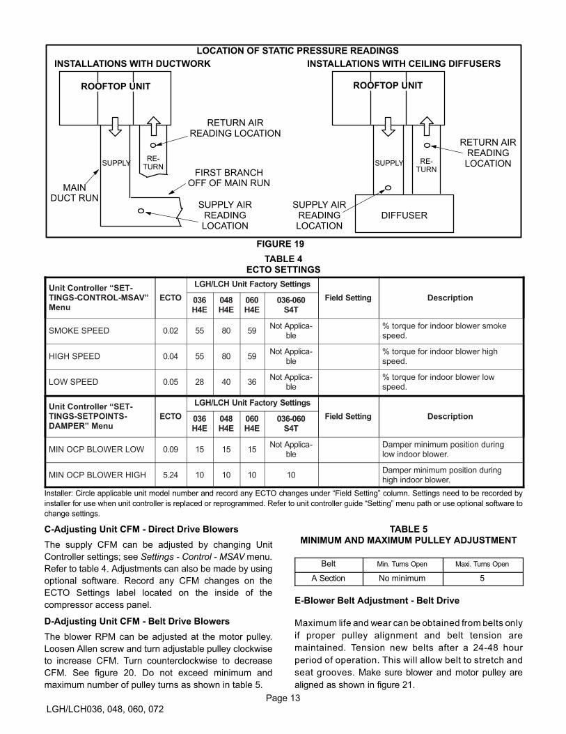
2- With all access panels in place, measure static
pressure external to unit (from supply to return).
Blower performance data is based on static pressure
readings taken in locations shown in figure 19.
Note - Static pressure readings can vary if not taken
where shown.
3- Measure the indoor blower wheel RPM.
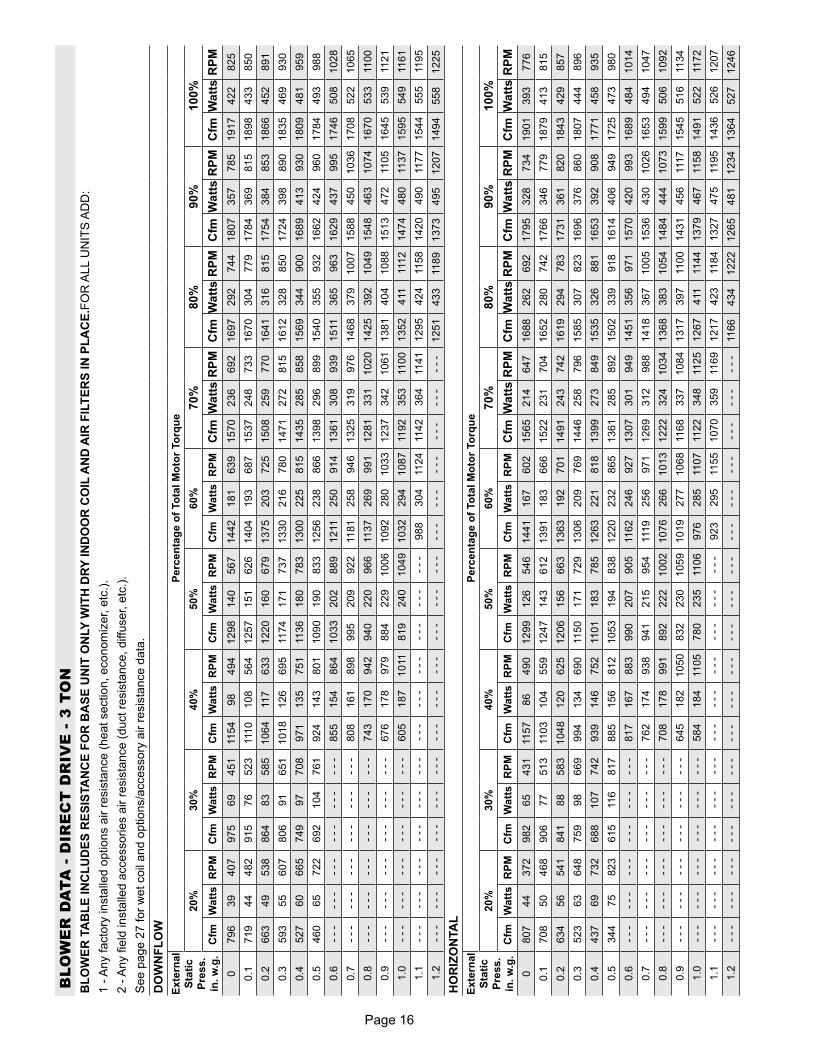
4- Referring to Page 16 through Page 26, use static
pressure and RPM readings to determine unit CFM.
Use Page 27 when installing units with any of the
options or accessories listed. Refer to table 3 for
minimum airflow when electric heat is installed.
TABLE 3MINIMUM AIRFLOW-LC UNITS WITH ELECTRIC HEAT
(BELT DRIVE)
KwCFM
Downflow & Horizontal Airflow
LCH036HE 1080
LCH048HE 1280
LCH060HE 1600
Page 13
LGH/LCH036, 048, 060, 072
FIGURE 19
LOCATION OF STATIC PRESSURE READINGS
SUPPLY AIRREADINGLOCATION
SUPPLYRE
TURN
INSTALLATIONS WITH DUCTWORK
SUPPLY RETURN
INSTALLATIONS WITH CEILING DIFFUSERS
MAINDUCT RUN
FIRST BRANCHOFF OF MAIN RUN
DIFFUSER
ROOFTOP UNIT ROOFTOP UNIT
SUPPLY AIRREADINGLOCATION
RETURN AIRREADING LOCATION
RETURN AIRREADINGLOCATION
TABLE 4ECTO SETTINGS
Unit Controller “SETTINGS-CONTROL-MSAV”Menu
ECTO
LGH/LCH Unit Factory Settings
Field Setting Description036H4E
048H4E
060H4E
036-060S4T
SMOKE SPEED 0.02 55 80 59Not Applica
ble% torque for indoor blower smokespeed.
HIGH SPEED 0.04 55 80 59Not Applica
ble% torque for indoor blower highspeed.
LOW SPEED 0.05 28 40 36Not Applica
ble% torque for indoor blower lowspeed.
Unit Controller “SETTINGS-SETPOINTS-DAMPER” Menu
ECTO
LGH/LCH Unit Factory Settings
Field Setting Description036H4E
048H4E
060H4E
036-060S4T
MIN OCP BLOWER LOW 0.09 15 15 15Not Applica
bleDamper minimum position duringlow indoor blower.
MIN OCP BLOWER HIGH 5.24 10 10 10 10Damper minimum position duringhigh indoor blower.
Installer: Circle applicable unit model number and record any ECTO changes under “Field Setting” column. Settings need to be recorded by
installer for use when unit controller is replaced or reprogrammed. Refer to unit controller guide “Setting” menu path or use optional software to
change settings.
C-Adjusting Unit CFM - Direct Drive Blowers
The supply CFM can be adjusted by changing Unit
Controller settings; see Settings - Control - MSAV menu.
Refer to table 4. Adjustments can also be made by using
optional software. Record any CFM changes on the
ECTO Settings label located on the inside of the
compressor access panel.
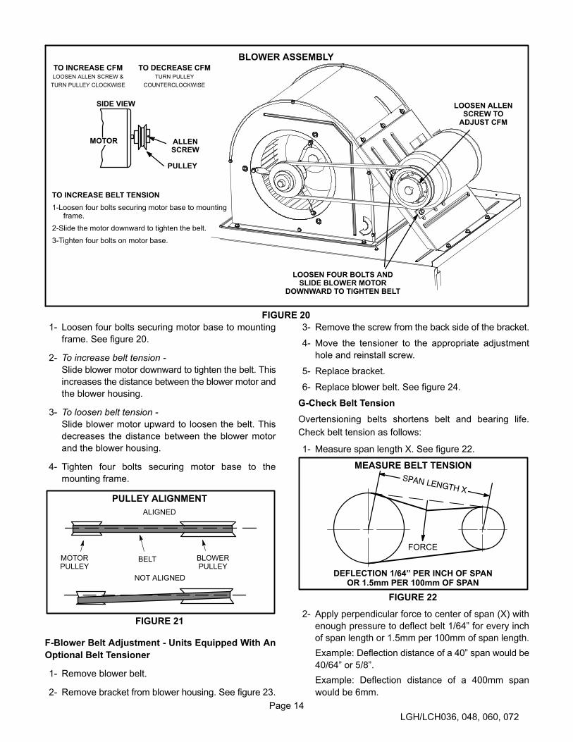
D-Adjusting Unit CFM - Belt Drive Blowers
The blower RPM can be adjusted at the motor pulley.
Loosen Allen screw and turn adjustable pulley clockwise
to increase CFM. Turn counterclockwise to decrease
CFM. See figure 20. Do not exceed minimum and
maximum number of pulley turns as shown in table 5.
TABLE 5
MINIMUM AND MAXIMUM PULLEY ADJUSTMENT
Belt Min. Turns Open Maxi. Turns Open
A Section No minimum 5
E-Blower Belt Adjustment - Belt Drive
Maximum life and wear can be obtained from belts only
if proper pulley alignment and belt tension are
maintained. Tension new belts after a 24-48 hour
period of operation. This will allow belt to stretch and
seat grooves. Make sure blower and motor pulley are
aligned as shown in figure 21.
Page 14
LGH/LCH036, 048, 060, 072
BLOWER ASSEMBLY
TO INCREASE BELT TENSION
1-Loosen four bolts securing motor base to mountingframe.
2-Slide the motor downward to tighten the belt.
3-Tighten four bolts on motor base.
TO INCREASE CFMLOOSEN ALLEN SCREW &
TURN PULLEY CLOCKWISE
TO DECREASE CFMTURN PULLEY
COUNTERCLOCKWISE
FIGURE 20
PULLEY
MOTOR
SIDE VIEW
ALLENSCREW
LOOSEN FOUR BOLTS ANDSLIDE BLOWER MOTOR
DOWNWARD TO TIGHTEN BELT
LOOSEN ALLENSCREW TO
ADJUST CFM
1- Loosen four bolts securing motor base to mounting
frame. See figure 20.
2- To increase belt tension -
Slide blower motor downward to tighten the belt. This
increases the distance between the blower motor and
the blower housing.
3- To loosen belt tension -
Slide blower motor upward to loosen the belt. This
decreases the distance between the blower motor
and the blower housing.
4- Tighten four bolts securing motor base to the
mounting frame.
FIGURE 21
PULLEY ALIGNMENT
BELT BLOWERPULLEY
MOTORPULLEY
NOT ALIGNED
ALIGNED
F-Blower Belt Adjustment - Units Equipped With An
Optional Belt Tensioner
1- Remove blower belt.
2- Remove bracket from blower housing. See figure 23.
3- Remove the screw from the back side of the bracket.
4- Move the tensioner to the appropriate adjustment
hole and reinstall screw.
5- Replace bracket.
6- Replace blower belt. See figure 24.
G-Check Belt Tension
Overtensioning belts shortens belt and bearing life.
Check belt tension as follows:
1- Measure span length X. See figure 22.
MEASURE BELT TENSION
FIGURE 22
DEFLECTION 1/64” PER INCH OF SPANOR 1.5mm PER 100mm OF SPAN
FORCE
2- Apply perpendicular force to center of span (X) with
enough pressure to deflect belt 1/64” for every inch
of span length or 1.5mm per 100mm of span length.
Example: Deflection distance of a 40” span would be
40/64” or 5/8”.
Example: Deflection distance of a 400mm span
would be 6mm.

Page 15
LGH/LCH036, 048, 060, 072
3- Measure belt deflection force. For a used belt, the
deflection force should be 5 lbs. (35kPa). A new belt
deflection force should be 7 lbs. (48kPa).
A force below these values indicates an
undertensioned belt. A force above these values
indicates an overtensioned belt.
H-Field-Furnished Blower Drives
For field-furnished blower drives, use page 19 through 26
to determine BHP and RPM required. Reference Page 27
to determine the drive kit number. Reference table 6 for
manufacturer's drive numbers.
FIGURE 23
ADJUST BELT TENSIONER
MAXIMUM
TENSION
MINIMUM
TENSION
INDICATOR SHOULD BE
BETWEEN MINIMUM AND
MAXIMUM TENSION LINES
FACTORY-SET
POSITION
TIGHTER
BELT
POSITION
TENSIONER
TIGHTEST
BELT
POSITION
BRACKET
INSTALL BELT
FIGURE 24
1
2
3
4
TENSIONERDRIVER
PULLEY
DRIVEN
PULLEY
ROTATE DRIVEN
PULLEY TO SEAT BELT
Page 16
BLO
WE
R D
ATA
- D
IRE
CT
DR
IVE
- 3
TO
NB
LOW
ER T
AB
LE IN
CLU
DES
RES
ISTA
NC
E FO
R B
ASE
UN
IT O
NLY
WIT
H D
RY IN
DO
OR
CO
IL A
ND
AIR
FIL
TER
S IN
PLA
CE.
FOR
ALL
UN
ITS
AD
D:
1 - A
ny fa
ctor
y in
stal
led
optio
ns a
ir re
sist
ance
(hea
t sec
tion,
eco
nom
izer
, etc
.).2
- Any
fiel
d in
stal
led
acce
ssor
ies
air r
esis
tanc
e (d
uct r
esis
tanc
e, d
iffus
er, e
tc.).
See
pag
e 27
for w
et c
oil a
nd o
ptio
ns/a
cces
sory
air
resi
stan
ce d
ata.
DO
WN
FLO
WEx
tern
al
Stat
ic
Pres
s.
in. w
.g.
Perc
enta
ge o
f Tot
al M
otor
Tor
que
20%
30%
40%
50%
60%
70%
80%
90%
100%
Cfm
Wat
tsR
PMC
fmW
atts
RPM
Cfm
Wat
tsR
PMC
fmW
atts
RPM
Cfm
Wat
tsR
PMC
fmW
atts
RPM
Cfm
Wat
tsR
PMC
fmW
atts
RPM
Cfm
Wat
tsR
PM0
796
3940
797
569
451
1154
9849
412
9814
056
714
4218
163
915
7023
669
216
9729
274
418
0735
778
519
1742
282
50.
171
944
482
915
7652
311
1010
856
412
5715
162
614
0419
368
715
3724
873
316
7030
477
917
8436
981
518
9843
385
00.
266
349
538
864
8358
510
6411
763
312
2016
067
913
7520
372
515
0825
977
016
4131
681
517
5438
485
318
6645
289
10.
359
355
607
806
9165
110
1812
669
511
7417
173
713
3021
678
014
7127
281
516
1232
885
017
2439
889
018
3546
993
00.
452
760
665
749
9770
897
113
575
111
3618
078
313
0022
581
514
3528
585
815
6934
490
016
8941
393
018
0948
195
90.
546
065
722
692
104
761
924
143
801
1090
190
833
1256
238
866
1398
296
899
1540
355
932
1662
424
960
1784
493
988
0.6
- - -
- - -
- - -
- - -
- - -
- - -
855
154
864
1033
202
889
1211
250
914
1361
308
939
1511
365
963
1629
437
995
1746
508
1028
0.7
- - -
- - -
- - -
- - -
- - -
- - -
808
161
898
995
209
922
1181
258
946
1325
319
976
1468
379
1007
1588
450
1036
1708
522
1065
0.8
- - -
- - -
- - -
- - -
- - -
- - -
743
170
942
940
220
966
1137
269
991
1281
331
1020
1425
392
1049
1548
463
1074
1670
533
1100
0.9
- - -
- - -
- - -
- - -
- - -
- - -
676
178
979
884
229
1006
1092
280
1033
1237
342
1061
1381
404
1088
1513
472
1105
1645
539
1121
1.0
- - -
- - -
- - -
- - -
- - -
- - -
605
187
1011
819
240
1049
1032
294
1087
1192
353
1100
1352
411
1112
1474
480
1137
1595
549
1161
1.1
- - -
- - -
- - -
- - -
- - -
- - -
- - -
- - -
- - -
- - -
- - -
- - -
988
304
1124
1142
364
1141
1295
424
1158
1420
490
1177
1544
555
1195
1.2
- - -
- - -
- - -
- - -
- - -
- - -
- - -
- - -
- - -
- - -
- - -
- - -
- - -
- - -
- - -
- - -
- - -
- - -
1251
433
1 189
1373
495
1207
1494
558
1225
HO
RIZ
ON
TAL
Exte
rnal
St
atic
Pr
ess.
in
. w.g
.
Perc
enta
ge o
f Tot
al M
otor
Tor
que
20%
30%
40%
50%
60%
70%
80%
90%
100%
Cfm
Wat
tsR
PMC
fmW
atts
RPM
Cfm
Wat
tsR
PMC
fmW
atts
RPM
Cfm
Wat
tsR
PMC
fmW
atts
RPM
Cfm
Wat
tsR
PMC
fmW
atts
RPM
Cfm
Wat
tsR
PM0
807
4437
298
265
431
1157
8649
012
9912
654
614
4116
760
215
6521
464
716
8826
269
217
9532
873
419
0139
377
60.
170
850
468
906
7751
311
0310
455
912
4714
361
213
9118
366
615
2223
170
416
5228
074
217
6634
677
918
7941
381
50.
263
456
541
841
8858
310
4812
062
512
0615
666
313
6319
270
114
9124
374
216
1929
478
317
3136
182
018
4342
985
70.
352
363
648
759
9866
999
413
469
011
5017
172
913
0620
976
914
4625
879
615
8530
782
316
9637
686
018
0744
489
60.
443
769
732
688
107
742
939
146
752
1101
183
785
1263
221
818
1399
273
849
1535
326
881
1653
392
908
1771
458
935
0.5
344
7582
361
511
681
788
515
681
210
5319
483
812
2023
286
513
6128
589
215
0233
991
816
1440
694
917
2547
398
00.
6- -
-- -
-- -
-- -
-- -
-- -
-81
716
788
399
020
790
511
6224
692
713
0730
194
914
5135
697
115
7042
099
316
8948
410
140.
7- -
-- -
-- -
-- -
-- -
-- -
-76
217
493
894
121
595
411
1925
697
112
6931
298
814
1836
710
0515
3643
010
2616
5349
410
470.
8- -
-- -
-- -
-- -
-- -
-- -
-70
817
899
189
222
210
0210
7626
610
1312
2232
410
3413
6838
310
5414
8444
410
7315
9950
610
920.
9- -
-- -
-- -
-- -
-- -
-- -
-64
518
210
5083
223
010
5910
1927
710
6811
6833
710
8413
1739
711
0014
3145
611
1715
4551
611
341.
0- -
-- -
-- -
-- -
-- -
-- -
-58
418
411
0578
023
511
0697
628
511
0711
2234
811
2512
6741
111
4413
7946
711
5814
9152
211
721.
1- -
-- -
-- -
-- -
-- -
-- -
-- -
-- -
-- -
-- -
-- -
-- -
-92
329
511
5510
7035
911
6912
1742
311
8413
2747
511
9514
3652
612
071.
2- -
-- -
-- -
-- -
-- -
-- -
-- -
-- -
-- -
-- -
-- -
-- -
-- -
-- -
-- -
-- -
-- -
-- -
-1 1
6643
412
2212
6548
112
3413
6452
712
46

Page 17
BLO
WE
R D
ATA
- D
IRE
CT
DR
IVE
- 4
TO
NB
LOW
ER T
AB
LE IN
CLU
DES
RES
ISTA
NC
E FO
R B
ASE
UN
IT O
NLY
WIT
H D
RY IN
DO
OR
CO
IL A
ND
AIR
FIL
TER
S IN
PLA
CE.
FOR
ALL
UN
ITS
AD
D:
1 - A
ny fa
ctor
y in
stal
led
optio
ns a
ir re
sist
ance
(hea
t sec
tion,
eco
nom
izer
, etc
.).2
- Any
fiel
d in
stal
led
acce
ssor
ies
air r
esis
tanc
e (d
uct r
esis
tanc
e, d
iffus
er, e
tc.).
See
pag
e 27
for w
et c
oil a
nd o
ptio
ns/a
cces
sory
air
resi
stan
ce d
ata.
DO
WN
FLO
WEx
tern
al
Stat
ic
Pres
s.
in. w
.g.
Perc
enta
ge o
f Tot
al M
otor
Tor
que
20%
30%
40%
50%
60%
70%
80%
90%
100%
Cfm
Wat
tsR
PMC
fmW
atts
RPM
Cfm
Wat
tsR
PMC
fmW
atts
RPM
Cfm
Wat
tsR
PMC
fmW
atts
RPM
Cfm
Wat
tsR
PMC
fmW
atts
RPM
Cfm
Wat
tsR
PM
010
4880
507
1261
135
582
1473
190
657
1655
274
729
1836
359
801
1987
461
863
2137
563
924
2291
698
975
2445
832
1025
0.1
1000
8856
012
1814
663
314
3620
470
616
2428
977
118
1237
483
619
6547
989
621
1858
395
622
6171
610
0424
0384
910
520.
294
497
624
1177
156
683
1409
214
743
1595
304
812
1781
393
881
1940
497
934
2098
602
986
2235
729
1032
2372
856
1077
0.3
906
104
666
1139
166
728
1372
228
790
1561
320
858
1750
412
925
1915
515
970
2079
619
1015
2210
741
1058
2341
863
1100
0.4
849
113
728
1093
177
783
1336
241
837
1531
333
897
1726
425
957
1889
532
1004
2052
639
1051
2177
754
1090
2302
869
1129
0.5
793
121
790
1047
188
837
1300
254
883
1501
346
935
1702
438
987
1864
548
1036
2026
657
1085
2145
766
1120
2263
874
1155
0.6
- - -
- - -
- - -
- - -
- - -
- - -
1263
267
929
1467
361
978
1671
454
1027
1836
564
1071
2000
673
1116
2116
775
1145
2232
876
1175
0.7
- - -
- - -
- - -
- - -
- - -
- - -
1226
280
974
1433
375
1019
1639
470
1065
1807
578
1104
1974
686
1144
2080
782
1173
2186
878
1203
0.8
- - -
- - -
- - -
- - -
- - -
- - -
1195
291
1012
1402
388
1057
1608
485
1101
1778
591
1135
1948
697
1169
2052
787
1195
2155
878
1220
0.9
- - -
- - -
- - -
- - -
- - -
- - -
1162
304
1060
1367
401
1097
1572
498
1134
1741
603
1168
1909
708
1202
2009
792
1223
2109
875
1244
1.0
- - -
- - -
- - -
- - -
- - -
- - -
1133
316
1104
1333
414
1136
1533
511
1167
1702
612
1198
1870
714
1229
1959
791
1251
2047
868
1272
1.1
- - -
- - -
- - -
- - -
- - -
- - -
- - -
- - -
- - -
- - -
- - -
- - -
1490
524
1200
1654
618
1228
1817
713
1256
1909
786
1273
2000
859
1289
1.2
- - -
- - -
- - -
- - -
- - -
- - -
- - -
- - -
- - -
- - -
- - -
- - -
- - -
- - -
- - -
- - -
- - -
- - -
1765
701
1272
1844
771
1293
1923
840
1314
HO
RIZ
ON
TAL
Exte
rnal
St
atic
Pr
ess.
in
. w.g
.
Perc
enta
ge o
f Tot
al M
otor
Tor
que
20%
30%
40%
50%
60%
70%
80%
90%
100%
Cfm
Wat
tsR
PMC
fmW
atts
RPM
Cfm
Wat
tsR
PMC
fmW
atts
RPM
Cfm
Wat
tsR
PMC
fmW
atts
RPM
Cfm
Wat
tsR
PMC
fmW
atts
RPM
Cfm
Wat
tsR
PM
010
2580
472
1238
131
552
1450
182
632
1626
254
702
1802
326
771
1936
414
824
2071
502
878
2231
634
931
2391
767
983
0.1
978
8554
611
9913
861
014
2019
167
516
0126
573
817
8133
980
119
3044
186
220
7954
492
322
2266
396
823
6578
310
130.
292
789
602
1157
145
661
1387
201
720
1568
279
783
1749
357
845
1906
458
897
2062
559
949
2205
679
993
2348
798
1038
0.3
851
9868
410
9815
673
113
4421
477
715
3129
583
317
1737
588
818
7647
893
820
3558
198
821
6669
410
3022
9780
710
720.
480
110
573
810
5116
678
513
0022
783
214
9330
988
116
8539
293
018
4749
697
720
0960
010
2321
2870
710
6422
4781
311
050.
572
511
881
799
117
985
012
5623
988
314
5532
492
616
5340
897
018
1451
610
1919
7462
310
6820
9172
010
9922
0781
711
300.
6- -
-- -
-- -
-- -
-- -
-- -
-12
1225
193
114
1733
796
916
2142
310
0817
8453
110
5319
4763
810
9820
5772
911
2621
6682
011
540.
7- -
-- -
-- -
-- -
-- -
-- -
-11
6926
397
513
8035
010
1015
9043
710
4517
5654
410
8619
2165
111
2720
1473
611
5721
0682
111
870.
8- -
-- -
-- -
-- -
-- -
-- -
-11
1427
710
2713
3136
610
5915
4745
410
9117
1756
011
2618
8666
611
6119
7674
311
8420
6682
112
070.
9- -
-- -
-- -
-- -
-- -
-- -
-10
6229
010
7712
8338
011
0615
0447
011
3516
6957
511
7018
3368
012
0419
1974
912
2020
0581
712
361.
0- -
-- -
-- -
-- -
-- -
-- -
-10
0730
411
2712
4039
211
4714
7348
111
6616
2758
412
0217
8068
712
3818
5374
812
5319
2580
912
691.
1- -
-- -
-- -
-- -
-- -
-- -
-- -
-- -
-- -
-- -
-- -
-- -
-14
2949
712
1115
6959
012
4017
0968
312
6917
8774
112
8018
6479
912
911.
2- -
-- -
-- -
-- -
-- -
-- -
-- -
-- -
-- -
-- -
-- -
-- -
-- -
-- -
-- -
-- -
-- -
-- -
-16
0465
112
8416
8471
413
0317
6377
713
21

Page 18
BLO
WE
R D
ATA
- D
IRE
CT
DR
IVE
- 5
TO
N
BLO
WER
TA
BLE
INC
LUD
ES R
ESIS
TAN
CE
FOR
BA
SE U
NIT
ON
LY W
ITH
DRY
IND
OO
R C
OIL
AN
D A
IR F
ILTE
RS
IN P
LAC
E.FO
R A
LL U
NIT
S A
DD
:1
- Any
fact
ory
inst
alle
d op
tions
air
resi
stan
ce (h
eat s
ectio
n, e
cono
miz
er, e
tc.).
2 - A
ny fi
eld
inst
alle
d ac
cess
orie
s ai
r res
ista
nce
(duc
t res
ista
nce,
diff
user
, etc
.).S
ee p
age
27 fo
r wet
coi
l and
opt
ions
/acc
esso
ry a
ir re
sist
ance
dat
a.
DO
WN
FLO
WEx
tern
al
Stat
ic
Pres
s.
in. w
.g.
Perc
enta
ge o
f Tot
al M
otor
Tor
que
20%
30%
40%
50%
60%
70%
80%
90%
100%
Cfm
Wat
tsR
PMC
fmW
atts
RPM
Cfm
Wat
tsR
PMC
fmW
atts
RPM
Cfm
Wat
tsR
PMC
fmW
atts
RPM
Cfm
Wat
tsR
PMC
fmW
atts
RPM
Cfm
Wat
tsR
PM
011
3279
438
1353
146
524
1575
212
610
1765
300
670
1954
388
730
2126
513
796
2298
638
861
2445
792
913
2591
946
965
0.1
1061
8649
413
0515
556
815
4822
364
117
4331
570
219
3740
776
421
1053
182
322
8265
488
324
2680
893
525
7096
398
70.
299
094
550
1253
165
614
1516
236
678
1716
330
735
1916
423
793
2088
549
851
2260
675
910
2405
827
959
2549
979
1009
0.3
920
102
606
1202
175
659
1484
248
713
1687
345
770
1890
442
828
2065
568
882
2239
694
937
2384
844
983
2528
994
1030
0.4
849
111
662
1151
185
705
1452
260
747
1658
360
804
1863
460
861
2041
586
911
2218
713
962
2363
861
1006
2508
1009
1050
0.5
779
121
718
1094
198
754
1410
275
790
1626
374
838
1842
473
886
2020
601
936
2197
730
987
2342
876
1028
2487
1023
1070
0.6
- - -
- - -
- - -
- - -
- - -
- - -
1368
289
830
1589
390
876
1810
492
921
1993
619
966
2176
746
1010
2316
895
1054
2456
1043
1099
0.7
- - -
- - -
- - -
- - -
- - -
- - -
1325
303
868
1552
406
911
1778
509
954
1966
635
993
2154
761
1033
2295
908
1075
2435
1055
1117
0.8
- - -
- - -
- - -
- - -
- - -
- - -
1261
321
920
1504
423
952
1746
524
984
1934
653
1024
2122
782
1064
2268
925
1100
2414
1067
1135
0.9
- - -
- - -
- - -
- - -
- - -
- - -
1211
337
964
1462
437
988
1714
538
1012
1902
669
1053
2090
801
1094
2237
942
1127
2383
1084
1161
1.0
- - -
- - -
- - -
- - -
- - -
- - -
1151
354
1013
1412
454
1029
1672
553
1045
1871
682
1078
2069
811
1112
2211
955
1149
2352
1099
1185
1.1
- - -
- - -
- - -
- - -
- - -
- - -
- - -
- - -
- - -
- - -
- - -
- - -
1629
566
1073
1828
698
1109
2027
830
1146
2174
971
1177
2321
1112
1208
1.2
- - -
- - -
- - -
- - -
- - -
- - -
- - -
- - -
- - -
- - -
- - -
- - -
- - -
- - -
- - -
- - -
- - -
- - -
1984
844
1175
2137
984
1202
2290
1124
1230
HO
RIZ
ON
TAL
Exte
rnal
St
atic
Pr
ess.
in
. w.g
.
Perc
enta
ge o
f Tot
al M
otor
Tor
que
20%
30%
40%
50%
60%
70%
80%
90%
100%
Cfm
Wat
tsR
PMC
fmW
atts
RPM
Cfm
Wat
tsR
PMC
fmW
atts
RPM
Cfm
Wat
tsR
PMC
fmW
atts
RPM
Cfm
Wat
tsR
PMC
fmW
atts
RPM
Cfm
Wat
tsR
PM
011
2782
426
1367
141
504
1607
200
582
1806
296
644
2005
391
706
2167
495
764
2328
599
822
2463
749
872
2598
899
922
0.1
1071
8647
613
2614
854
315
8021
061
017
8131
167
519
8141
174
021
4551
679
523
0962
084
924
5677
589
826
0293
194
70.
210
1091
529
1268
160
598
1525
229
668
1735
332
724
1945
434
781
2117
537
828
2289
640
875
2438
795
921
2587
949
967
0.3
930
100
597
1214
169
647
1497
239
696
1707
345
755
1917
452
814
2093
556
857
2269
660
900
2417
817
948
2565
975
995
0.4
869
109
646
1156
184
699
1442
258
751
1665
364
798
1888
469
845
2066
577
889
2243
685
933
2393
842
978
2543
998
1022
0.5
813
119
689
1114
193
734
1414
267
778
1637
376
827
1860
485
876
2039
597
920
2217
709
963
2373
861
1002
2528
1013
1040
0.6
- - -
- - -
- - -
- - -
- - -
- - -
1358
286
831
1595
394
868
1832
501
905
2012
616
949
2191
731
993
2349
882
1028
2506
1033
1064
0.7
- - -
- - -
- - -
- - -
- - -
- - -
1330
296
857
1560
409
903
1789
523
949
1977
638
985
2164
753
1020
2324
902
1054
2484
1052
1088
0.8
- - -
- - -
- - -
- - -
- - -
- - -
1275
315
908
1518
426
942
1761
536
977
1950
655
1011
2138
773
1046
2296
923
1081
2454
1073
1116
0.9
- - -
- - -
- - -
- - -
- - -
- - -
1233
329
946
1483
439
975
1732
549
1004
1922
670
1037
2112
792
1071
2272
939
1104
2432
1087
1136
1.0
- - -
- - -
- - -
- - -
- - -
- - -
1192
343
982
1441
455
1012
1690
567
1043
1881
692
1074
2072
818
1105
2237
960
1133
2402
1102
1161
1.1
- - -
- - -
- - -
- - -
- - -
- - -
- - -
- - -
- - -
- - -
- - -
- - -
1662
578
1068
1854
706
1097
2046
833
1126
2206
975
1157
2365
1117
1188
1.2
- - -
- - -
- - -
- - -
- - -
- - -
- - -
- - -
- - -
- - -
- - -
- - -
- - -
- - -
- - -
- - -
- - -
- - -
1994
861
1 163
2165
993
1185
2336
1125
1206

Page 19
BLOWER DATA - BELT DRIVE - 3 TONBLOWER TABLE INCLUDES RESISTANCE FOR BASE UNIT ONLY WITH DRY INDOOR COIL AND AIR FILTERS IN PLACE. FOR ALL UNITS ADD: 1 - Any factory installed options air resistance (heat section, economizer, etc.). 2 - Any field installed accessories air resistance (duct resistance, diffuser, etc.).See page 27 for blower motors and drives and wet coil and options/accessory air resistance data.
DOWNFLOW
Air Volume (cfm)
External Static (in.w.g.)
0.10 0.20 0.30 0.40 0.50 0.60 0.70 0.80 0.9 1.0
RPM BHP RPM BHP RPM BHP RPM BHP RPM BHP RPM BHP RPM BHP RPM BHP RPM BHP RPM BHP
700 453 0.07 523 0.11 596 0.14 679 0.17 762 0.18 828 0.21 878 0.24 927 0.26 979 0.29 1029 0.31
800 471 0.09 542 0.13 614 0.16 696 0.19 777 0.21 841 0.23 889 0.26 938 0.29 990 0.31 1042 0.34
900 493 0.11 563 0.15 634 0.19 715 0.21 793 0.23 854 0.26 902 0.29 950 0.32 1002 0.34 1054 0.36
1000 517 0.14 587 0.18 657 0.21 736 0.24 811 0.26 869 0.29 916 0.32 964 0.35 1015 0.37 1067 0.4
1100 544 0.17 613 0.21 683 0.24 759 0.27 831 0.3 886 0.32 931 0.36 978 0.38 1028 0.41 1078 0.43
1200 574 0.2 643 0.24 711 0.27 784 0.3 852 0.33 904 0.36 947 0.39 993 0.42 1042 0.45 1091 0.47
1300 608 0.24 676 0.28 743 0.31 812 0.34 875 0.37 923 0.4 964 0.44 1010 0.46 1057 0.49 1104 0.51
1400 645 0.28 711 0.31 776 0.35 842 0.38 898 0.41 942 0.44 983 0.48 1028 0.51 1074 0.53 1120 0.56
Air Volume (cfm)
External Static (in.w.g.)
1.1 1.2 1.3 1.4 1.5 1.6 1.7 1.8 1.9 2.0
RPM BHP RPM BHP RPM BHP RPM BHP RPM BHP RPM BHP RPM BHP RPM BHP RPM BHP RPM BHP
700 1078 0.33 1124 0.36 - - - - - - - - - - - - - - - - - - - - - - - - - - - - - - - - - - - - - - - - - - - - - - - -
800 1091 0.36 1137 0.39 1180 0.41 1221 0.44 1260 0.47 - - - - - - - - - - - - - - - - - - - - - - - - - - - - - -
900 1105 0.39 1150 0.42 1192 0.45 1232 0.47 1270 0.5 1307 0.53 1345 0.56 1382 0.59 1420 0.62 - - - - - -
1000 1117 0.42 1162 0.45 1203 0.48 1242 0.51 1279 0.54 1316 0.57 1353 0.6 1390 0.63 1427 0.66 1465 0.7
1100 1126 0.46 1171 0.49 1212 0.52 1251 0.56 1288 0.59 1325 0.62 1361 0.65 1397 0.68 1433 0.71 1470 0.75
1200 1137 0.5 1180 0.54 1222 0.57 1260 0.6 1298 0.64 1334 0.67 1369 0.7 1404 0.73 1440 0.77 1477 0.8
1300 1149 0.55 1191 0.58 1232 0.62 1270 0.65 1307 0.69 1343 0.72 1378 0.76 1413 0.79 1449 0.82 1486 0.86
1400 1163 0.6 1204 0.63 1243 0.67 1281 0.71 1317 0.74 1353 0.78 1388 0.82 1423 0.85 1459 0.89 1496 0.92
Page 20
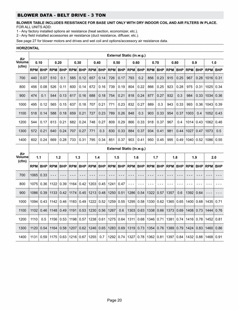
BLOWER DATA - BELT DRIVE - 3 TONBLOWER TABLE INCLUDES RESISTANCE FOR BASE UNIT ONLY WITH DRY INDOOR COIL AND AIR FILTERS IN PLACE. FOR ALL UNITS ADD: 1 - Any factory installed options air resistance (heat section, economizer, etc.). 2 - Any field installed accessories air resistance (duct resistance, diffuser, etc.).See page 27 for blower motors and drives and wet coil and options/accessory air resistance data.
HORIZONTAL
Air Volume (cfm)
External Static (in.w.g.)
0.10 0.20 0.30 0.40 0.50 0.60 0.70 0.80 0.9 1.0
RPM BHP RPM BHP RPM BHP RPM BHP RPM BHP RPM BHP RPM BHP RPM BHP RPM BHP RPM BHP
700 440 0.07 510 0.1 585 0.12 657 0.14 726 0.17 793 0.2 856 0.23 915 0.25 967 0.28 1016 0.31
800 456 0.08 526 0.11 600 0.14 672 0.16 739 0.19 804 0.22 866 0.25 923 0.28 975 0.31 1025 0.34
900 474 0.1 544 0.13 617 0.16 688 0.18 754 0.21 818 0.24 877 0.27 932 0.3 984 0.33 1034 0.36
1000 495 0.12 565 0.15 637 0.18 707 0.21 771 0.23 832 0.27 889 0.3 943 0.33 993 0.36 1043 0.39
1100 518 0.14 588 0.18 659 0.21 727 0.23 789 0.26 848 0.3 903 0.33 954 0.37 1003 0.4 1052 0.43
1200 544 0.17 613 0.21 682 0.24 748 0.27 809 0.29 866 0.33 918 0.37 967 0.4 1014 0.43 1062 0.46
1300 572 0.21 640 0.24 707 0.27 771 0.3 830 0.33 884 0.37 934 0.41 981 0.44 1027 0.47 1073 0.5
1400 602 0.24 669 0.28 733 0.31 795 0.34 851 0.37 903 0.41 950 0.45 995 0.49 1040 0.52 1086 0.55
Air Volume (cfm)
External Static (in.w.g.)
1.1 1.2 1.3 1.4 1.5 1.6 1.7 1.8 1.9 2.0
RPM BHP RPM BHP RPM BHP RPM BHP RPM BHP RPM BHP RPM BHP RPM BHP RPM BHP RPM BHP
700 1065 0.33 - - - - - - - - - - - - - - - - - - - - - - - - - - - - - - - - - - - - - - - - - - - - - - - - - - - - - -
800 1075 0.36 1122 0.39 1164 0.42 1203 0.45 1241 0.47 - - - - - - - - - - - - - - - - - - - - - - - - - - - - - -
900 1086 0.39 1133 0.42 1174 0.45 1213 0.48 1250 0.51 1286 0.54 1322 0.57 1357 0.6 1392 0.64 - - - - - -
1000 1094 0.43 1142 0.46 1183 0.49 1222 0.52 1259 0.55 1295 0.58 1330 0.62 1365 0.65 1400 0.68 1435 0.71
1100 1102 0.46 1148 0.49 1191 0.53 1230 0.56 1267 0.6 1303 0.63 1338 0.66 1373 0.69 1408 0.73 1444 0.76
1200 1110 0.5 1156 0.53 1198 0.57 1238 0.61 1275 0.64 1311 0.68 1346 0.71 1381 0.74 1416 0.78 1452 0.81
1300 1120 0.54 1164 0.58 1207 0.62 1246 0.65 1283 0.69 1319 0.73 1354 0.76 1389 0.79 1424 0.83 1460 0.86
1400 1131 0.59 1175 0.63 1216 0.67 1255 0.7 1292 0.74 1327 0.78 1362 0.81 1397 0.84 1432 0.88 1468 0.91
Page 21
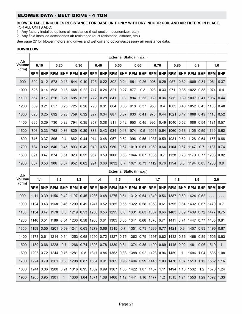
BLOWER DATA - BELT DRIVE - 4 TONBLOWER TABLE INCLUDES RESISTANCE FOR BASE UNIT ONLY WITH DRY INDOOR COIL AND AIR FILTERS IN PLACE. FOR ALL UNITS ADD: 1 - Any factory installed options air resistance (heat section, economizer, etc.). 2 - Any field installed accessories air resistance (duct resistance, diffuser, etc.).See page 27 for blower motors and drives and wet coil and options/accessory air resistance data.
DOWNFLOW
Air Volume (cfm)
External Static (in.w.g.)
0.10 0.20 0.30 0.40 0.50 0.60 0.70 0.80 0.9 1.0
RPM BHP RPM BHP RPM BHP RPM BHP RPM BHP RPM BHP RPM BHP RPM BHP RPM BHP RPM BHP
900 502 0.12 573 0.15 644 0.19 725 0.22 802 0.24 861 0.26 908 0.29 957 0.32 1009 0.34 1061 0.37
1000 528 0.14 598 0.18 668 0.22 747 0.24 821 0.27 877 0.3 923 0.33 971 0.35 1022 0.38 1074 0.4
1100 557 0.17 626 0.21 695 0.25 772 0.28 841 0.3 894 0.33 939 0.36 986 0.39 1037 0.41 1087 0.44
1200 589 0.21 657 0.25 725 0.28 798 0.31 864 0.33 913 0.37 956 0.4 1003 0.43 1052 0.45 1100 0.48
1300 625 0.25 692 0.28 759 0.32 827 0.34 887 0.37 933 0.41 975 0.44 1021 0.47 1068 0.49 1115 0.52
1400 665 0.29 730 0.32 794 0.35 857 0.38 911 0.42 953 0.45 995 0.49 1040 0.52 1086 0.54 1131 0.57
1500 706 0.33 768 0.36 829 0.39 886 0.43 934 0.46 974 0.5 1015 0.54 1060 0.56 1105 0.59 1149 0.62
1600 746 0.37 805 0.4 862 0.44 914 0.48 957 0.52 996 0.55 1037 0.59 1081 0.62 1126 0.64 1167 0.68
1700 784 0.42 840 0.45 893 0.49 940 0.53 980 0.57 1019 0.61 1060 0.64 1104 0.67 1147 0.7 1187 0.74
1800 821 0.47 874 0.51 923 0.55 967 0.59 1006 0.63 1044 0.67 1085 0.7 1128 0.73 1170 0.77 1208 0.82
1900 857 0.53 906 0.57 952 0.62 994 0.66 1032 0.7 1071 0.73 1112 0.76 1154 0.8 1194 0.85 1230 0.9
Air Volume (cfm)
External Static (in.w.g.)
1.1 1.2 1.3 1.4 1.5 1.6 1.7 1.8 1.9 2.0
RPM BHP RPM BHP RPM BHP RPM BHP RPM BHP RPM BHP RPM BHP RPM BHP RPM BHP RPM BHP
900 1111 0.39 1156 0.42 1197 0.45 1236 0.48 1275 0.51 1312 0.54 1349 0.56 1387 0.59 1424 0.62 - - - - - -
1000 1124 0.43 1168 0.46 1209 0.49 1247 0.52 1285 0.55 1322 0.58 1358 0.61 1395 0.64 1432 0.67 1470 0.7
1100 1134 0.47 1178 0.5 1219 0.53 1258 0.56 1295 0.6 1331 0.63 1367 0.66 1403 0.69 1439 0.72 1477 0.75
1200 1146 0.51 1189 0.54 1230 0.58 1268 0.61 1305 0.65 1341 0.68 1376 0.71 1411 0.74 1447 0.77 1485 0.81
1300 1159 0.55 1201 0.59 1241 0.63 1279 0.66 1315 0.7 1351 0.73 1386 0.77 1421 0.8 1457 0.83 1495 0.87
1400 1173 0.61 1214 0.64 1253 0.68 1290 0.72 1327 0.75 1362 0.79 1397 0.82 1432 0.86 1468 0.89 1506 0.93
1500 1189 0.66 1228 0.7 1266 0.74 1303 0.78 1339 0.81 1374 0.85 1409 0.89 1445 0.92 1481 0.96 1519 1
1600 1206 0.72 1244 0.76 1281 0.8 1317 0.84 1353 0.88 1388 0.92 1423 0.96 1459 1 1496 1.04 1535 1.08
1700 1224 0.79 1261 0.83 1298 0.87 1334 0.91 1369 0.95 1404 0.99 1440 1.03 1476 1.07 1513 1.12 1552 1.16
1800 1244 0.86 1280 0.91 1316 0.95 1352 0.99 1387 1.03 1422 1.07 1457 1.11 1494 1.16 1532 1.2 1570 1.24
1900 1265 0.95 1301 1 1336 1.04 1371 1.08 1406 1.12 1441 1.16 1477 1.2 1515 1.24 1553 1.29 1592 1.33
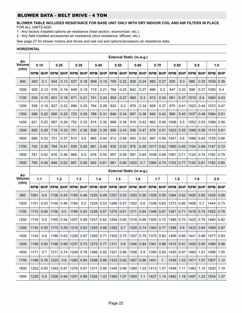
Page 22
BLOWER DATA - BELT DRIVE - 4 TONBLOWER TABLE INCLUDES RESISTANCE FOR BASE UNIT ONLY WITH DRY INDOOR COIL AND AIR FILTERS IN PLACE. FOR ALL UNITS ADD: 1 - Any factory installed options air resistance (heat section, economizer, etc.). 2 - Any field installed accessories air resistance (duct resistance, diffuser, etc.).See page 27 for blower motors and drives and wet coil and options/accessory air resistance data.
HORIZONTAL
Air Volume (cfm)
External Static (in.w.g.)
0.10 0.20 0.30 0.40 0.50 0.60 0.70 0.80 0.9 1.0
RPM BHP RPM BHP RPM BHP RPM BHP RPM BHP RPM BHP RPM BHP RPM BHP RPM BHP RPM BHP
900 483 0.1 554 0.13 627 0.16 699 0.19 765 0.22 826 0.24 882 0.27 935 0.3 986 0.33 1039 0.36
1000 505 0.12 576 0.16 648 0.19 719 0.21 784 0.24 842 0.27 896 0.3 947 0.33 998 0.37 1050 0.4
1100 530 0.15 601 0.18 671 0.21 741 0.24 804 0.27 860 0.3 912 0.34 961 0.37 1010 0.4 1060 0.43
1200 558 0.18 627 0.22 696 0.25 764 0.28 824 0.3 878 0.34 928 0.37 975 0.41 1023 0.44 1072 0.47
1300 588 0.22 656 0.25 723 0.28 788 0.31 846 0.34 897 0.38 945 0.42 990 0.45 1037 0.48 1084 0.51
1400 621 0.25 687 0.29 752 0.32 814 0.35 868 0.38 916 0.42 962 0.46 1006 0.5 1052 0.53 1098 0.56
1500 655 0.29 719 0.33 781 0.36 839 0.39 890 0.43 936 0.47 979 0.51 1023 0.55 1068 0.58 1113 0.61
1600 690 0.33 751 0.37 810 0.4 865 0.44 912 0.48 955 0.52 997 0.56 1041 0.6 1086 0.63 1129 0.66
1700 725 0.38 784 0.41 839 0.45 891 0.49 935 0.53 975 0.58 1017 0.62 1060 0.65 1104 0.68 1147 0.72
1800 761 0.42 816 0.46 868 0.5 916 0.55 957 0.59 997 0.64 1038 0.68 1081 0.71 1124 0.74 1165 0.79
1900 795 0.48 848 0.52 897 0.56 942 0.61 981 0.66 1020 0.7 1060 0.74 1103 0.77 1145 0.81 1183 0.85
Air Volume (cfm)
External Static (in.w.g.)
1.1 1.2 1.3 1.4 1.5 1.6 1.7 1.8 1.9 2.0
RPM BHP RPM BHP RPM BHP RPM BHP RPM BHP RPM BHP RPM BHP RPM BHP RPM BHP RPM BHP
900 1091 0.4 1138 0.43 1180 0.46 1220 0.49 1257 0.53 1293 0.56 1329 0.59 1364 0.62 1400 0.65 1435 0.69
1000 1101 0.43 1149 0.46 1190 0.5 1229 0.53 1266 0.57 1302 0.6 1338 0.63 1373 0.66 1408 0.7 1444 0.73
1100 1110 0.46 1156 0.5 1199 0.54 1238 0.57 1275 0.61 1311 0.64 1346 0.67 1381 0.71 1416 0.74 1452 0.78
1200 1119 0.5 1165 0.54 1207 0.58 1247 0.62 1284 0.65 1319 0.69 1355 0.72 1389 0.75 1425 0.79 1460 0.82
1300 1130 0.55 1175 0.59 1216 0.63 1255 0.66 1292 0.7 1328 0.74 1363 0.77 1398 0.8 1433 0.84 1469 0.87
1400 1143 0.6 1186 0.63 1226 0.67 1265 0.71 1302 0.75 1337 0.79 1372 0.82 1406 0.85 1441 0.89 1477 0.93
1500 1156 0.65 1198 0.69 1237 0.73 1275 0.77 1311 0.8 1346 0.84 1381 0.88 1415 0.91 1450 0.95 1486 0.98
1600 1171 0.7 1211 0.74 1249 0.78 1286 0.82 1321 0.86 1356 0.9 1390 0.93 1425 0.97 1460 1.01 1496 1.05
1700 1186 0.76 1225 0.8 1262 0.84 1298 0.88 1333 0.92 1367 0.96 1401 1 1436 1.03 1471 1.07 1507 1.12
1800 1202 0.83 1240 0.87 1276 0.91 1311 0.95 1345 0.99 1380 1.03 1413 1.07 1448 1.11 1483 1.15 1520 1.19
1900 1220 0.9 1256 0.94 1291 0.99 1326 1.03 1360 1.07 1393 1.1 1427 1.14 1462 1.18 1497 1.22 1534 1.27
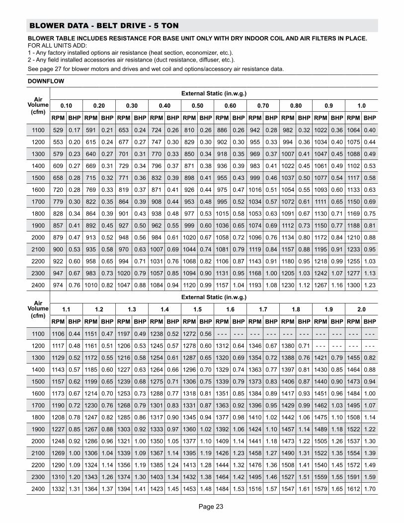
Page 23
BLOWER DATA - BELT DRIVE - 5 TONBLOWER TABLE INCLUDES RESISTANCE FOR BASE UNIT ONLY WITH DRY INDOOR COIL AND AIR FILTERS IN PLACE. FOR ALL UNITS ADD: 1 - Any factory installed options air resistance (heat section, economizer, etc.). 2 - Any field installed accessories air resistance (duct resistance, diffuser, etc.).See page 27 for blower motors and drives and wet coil and options/accessory air resistance data.
DOWNFLOW
Air Volume (cfm)
External Static (in.w.g.)
0.10 0.20 0.30 0.40 0.50 0.60 0.70 0.80 0.9 1.0
RPM BHP RPM BHP RPM BHP RPM BHP RPM BHP RPM BHP RPM BHP RPM BHP RPM BHP RPM BHP
1100 529 0.17 591 0.21 653 0.24 724 0.26 810 0.26 886 0.26 942 0.28 982 0.32 1022 0.36 1064 0.40
1200 553 0.20 615 0.24 677 0.27 747 0.30 829 0.30 902 0.30 955 0.33 994 0.36 1034 0.40 1075 0.44
1300 579 0.23 640 0.27 701 0.31 770 0.33 850 0.34 918 0.35 969 0.37 1007 0.41 1047 0.45 1088 0.49
1400 609 0.27 669 0.31 729 0.34 796 0.37 871 0.38 936 0.39 983 0.41 1022 0.45 1061 0.49 1102 0.53
1500 658 0.28 715 0.32 771 0.36 832 0.39 898 0.41 955 0.43 999 0.46 1037 0.50 1077 0.54 1117 0.58
1600 720 0.28 769 0.33 819 0.37 871 0.41 926 0.44 975 0.47 1016 0.51 1054 0.55 1093 0.60 1133 0.63
1700 779 0.30 822 0.35 864 0.39 908 0.44 953 0.48 995 0.52 1034 0.57 1072 0.61 1111 0.65 1150 0.69
1800 828 0.34 864 0.39 901 0.43 938 0.48 977 0.53 1015 0.58 1053 0.63 1091 0.67 1130 0.71 1169 0.75
1900 857 0.41 892 0.45 927 0.50 962 0.55 999 0.60 1036 0.65 1074 0.69 1112 0.73 1150 0.77 1188 0.81
2000 879 0.47 913 0.52 948 0.56 984 0.61 1020 0.67 1058 0.72 1096 0.76 1134 0.80 1172 0.84 1210 0.88
2100 900 0.53 935 0.58 970 0.63 1007 0.69 1044 0.74 1081 0.79 1119 0.84 1157 0.88 1195 0.91 1233 0.95
2200 922 0.60 958 0.65 994 0.71 1031 0.76 1068 0.82 1106 0.87 1143 0.91 1180 0.95 1218 0.99 1255 1.03
2300 947 0.67 983 0.73 1020 0.79 1057 0.85 1094 0.90 1131 0.95 1168 1.00 1205 1.03 1242 1.07 1277 1.13
2400 974 0.76 1010 0.82 1047 0.88 1084 0.94 1120 0.99 1157 1.04 1193 1.08 1230 1.12 1267 1.16 1300 1.23
Air Volume (cfm)
External Static (in.w.g.)
1.1 1.2 1.3 1.4 1.5 1.6 1.7 1.8 1.9 2.0
RPM BHP RPM BHP RPM BHP RPM BHP RPM BHP RPM BHP RPM BHP RPM BHP RPM BHP RPM BHP
1100 1106 0.44 1151 0.47 1197 0.49 1238 0.52 1272 0.56 - - - - - - - - - - - - - - - - - - - - - - - - - - - - - -
1200 1117 0.48 1161 0.51 1206 0.53 1245 0.57 1278 0.60 1312 0.64 1346 0.67 1380 0.71 - - - - - - - - - - - -
1300 1129 0.52 1172 0.55 1216 0.58 1254 0.61 1287 0.65 1320 0.69 1354 0.72 1388 0.76 1421 0.79 1455 0.82
1400 1143 0.57 1185 0.60 1227 0.63 1264 0.66 1296 0.70 1329 0.74 1363 0.77 1397 0.81 1430 0.85 1464 0.88
1500 1157 0.62 1199 0.65 1239 0.68 1275 0.71 1306 0.75 1339 0.79 1373 0.83 1406 0.87 1440 0.90 1473 0.94
1600 1173 0.67 1214 0.70 1253 0.73 1288 0.77 1318 0.81 1351 0.85 1384 0.89 1417 0.93 1451 0.96 1484 1.00
1700 1190 0.72 1230 0.76 1268 0.79 1301 0.83 1331 0.87 1363 0.92 1396 0.95 1429 0.99 1462 1.03 1495 1.07
1800 1208 0.78 1247 0.82 1285 0.86 1317 0.90 1345 0.94 1377 0.98 1410 1.02 1442 1.06 1475 1.10 1508 1.14
1900 1227 0.85 1267 0.88 1303 0.92 1333 0.97 1360 1.02 1392 1.06 1424 1.10 1457 1.14 1489 1.18 1522 1.22
2000 1248 0.92 1286 0.96 1321 1.00 1350 1.05 1377 1.10 1409 1.14 1441 1.18 1473 1.22 1505 1.26 1537 1.30
2100 1269 1.00 1306 1.04 1339 1.09 1367 1.14 1395 1.19 1426 1.23 1458 1.27 1490 1.31 1522 1.35 1554 1.39
2200 1290 1.09 1324 1.14 1356 1.19 1385 1.24 1413 1.28 1444 1.32 1476 1.36 1508 1.41 1540 1.45 1572 1.49
2300 1310 1.20 1343 1.26 1374 1.30 1403 1.34 1432 1.38 1464 1.42 1495 1.46 1527 1.51 1559 1.55 1591 1.59
2400 1332 1.31 1364 1.37 1394 1.41 1423 1.45 1453 1.48 1484 1.53 1516 1.57 1547 1.61 1579 1.65 1612 1.70

Page 24
BLOWER DATA - BELT DRIVE - 5 TONBLOWER TABLE INCLUDES RESISTANCE FOR BASE UNIT ONLY WITH DRY INDOOR COIL AND AIR FILTERS IN PLACE. FOR ALL UNITS ADD: 1 - Any factory installed options air resistance (heat section, economizer, etc.). 2 - Any field installed accessories air resistance (duct resistance, diffuser, etc.).See page 27 for blower motors and drives and wet coil and options/accessory air resistance data.
HORIZONTAL
Air Volume (cfm)
External Static (in.w.g.)
0.10 0.20 0.30 0.40 0.50 0.60 0.70 0.80 0.9 1.0
RPM BHP RPM BHP RPM BHP RPM BHP RPM BHP RPM BHP RPM BHP RPM BHP RPM BHP RPM BHP
1100 503 0.14 569 0.17 636 0.20 703 0.23 769 0.26 842 0.28 909 0.30 964 0.33 1008 0.36 1049 0.40
1200 525 0.16 590 0.20 657 0.23 722 0.26 787 0.29 857 0.31 921 0.34 974 0.37 1016 0.40 1056 0.43
1300 548 0.19 613 0.23 679 0.26 743 0.29 806 0.32 873 0.35 934 0.37 984 0.41 1026 0.44 1065 0.47
1400 574 0.22 638 0.26 702 0.30 765 0.33 827 0.36 891 0.39 949 0.41 996 0.45 1037 0.48 1076 0.51
1500 609 0.25 671 0.29 733 0.33 793 0.36 851 0.39 911 0.42 965 0.46 1010 0.49 1049 0.53 1088 0.56
1600 654 0.28 712 0.32 769 0.36 825 0.39 879 0.43 933 0.47 982 0.50 1024 0.54 1063 0.58 1101 0.61
1700 703 0.31 756 0.35 807 0.39 858 0.43 906 0.47 955 0.51 999 0.55 1039 0.59 1078 0.63 1117 0.66
1800 752 0.34 798 0.38 844 0.43 889 0.48 933 0.52 977 0.57 1017 0.61 1056 0.65 1094 0.68 1133 0.72
1900 796 0.38 837 0.43 878 0.48 918 0.53 958 0.58 997 0.62 1036 0.67 1074 0.71 1112 0.74 1151 0.77
2000 833 0.43 870 0.48 907 0.54 943 0.59 980 0.64 1018 0.69 1055 0.73 1093 0.77 1131 0.80 1170 0.83
2100 864 0.50 897 0.55 931 0.60 966 0.65 1002 0.71 1038 0.76 1075 0.80 1113 0.83 1151 0.87 1189 0.90
2200 887 0.57 920 0.62 953 0.67 988 0.73 1024 0.78 1060 0.83 1097 0.87 1135 0.90 1173 0.94 1210 0.98
2300 909 0.64 942 0.70 976 0.75 1011 0.81 1046 0.86 1083 0.91 1120 0.95 1157 0.98 1195 1.02 1231 1.06
2400 931 0.72 965 0.78 999 0.83 1035 0.89 1071 0.94 1108 0.99 1144 1.03 1181 1.07 1217 1.10 1252 1.15
Air Volume (cfm)
External Static (in.w.g.)
1.1 1.2 1.3 1.4 1.5 1.6 1.7 1.8 1.9 2.0
RPM BHP RPM BHP RPM BHP RPM BHP RPM BHP RPM BHP RPM BHP RPM BHP RPM BHP RPM BHP
1100 1090 0.42 1132 0.45 1175 0.47 1216 0.50 1257 0.53 1296 0.56 1334 0.59 1370 0.62 1405 0.65 1439 0.69
1200 1097 0.46 1139 0.49 1181 0.51 1222 0.54 1263 0.57 1301 0.60 1338 0.63 1374 0.67 1409 0.70 1443 0.74
1300 1106 0.50 1147 0.53 1189 0.55 1230 0.58 1270 0.61 1307 0.65 1344 0.68 1379 0.72 1414 0.75 1447 0.79
1400 1116 0.54 1157 0.57 1198 0.60 1239 0.63 1278 0.66 1315 0.70 1351 0.74 1385 0.77 1419 0.81 1452 0.85
1500 1128 0.59 1168 0.62 1209 0.64 1249 0.68 1287 0.71 1323 0.75 1358 0.79 1393 0.83 1426 0.87 1458 0.91
1600 1141 0.64 1181 0.67 1222 0.70 1261 0.73 1298 0.77 1333 0.81 1367 0.85 1401 0.89 1433 0.93 1465 0.97
1700 1156 0.69 1196 0.72 1235 0.75 1273 0.79 1309 0.83 1344 0.87 1377 0.91 1410 0.96 1442 1.00 1473 1.04
1800 1172 0.75 1211 0.78 1250 0.81 1287 0.85 1322 0.90 1355 0.94 1388 0.98 1420 1.02 1451 1.07 1482 1.11
1900 1190 0.81 1228 0.84 1265 0.88 1301 0.92 1335 0.97 1367 1.01 1399 1.05 1431 1.10 1462 1.14 1492 1.18
2000 1208 0.87 1245 0.91 1281 0.96 1316 1.00 1349 1.04 1380 1.09 1412 1.13 1443 1.18 1473 1.22 1503 1.26
2100 1227 0.94 1263 0.99 1298 1.04 1331 1.08 1363 1.13 1394 1.17 1425 1.22 1455 1.26 1485 1.31 1515 1.35
2200 1246 1.02 1281 1.07 1315 1.12 1347 1.17 1379 1.22 1409 1.26 1439 1.31 1469 1.36 1499 1.40 1529 1.45
2300 1266 1.11 1300 1.16 1333 1.22 1364 1.27 1395 1.32 1424 1.36 1454 1.41 1484 1.46 1513 1.50 1543 1.55
2400 1286 1.20 1319 1.26 1351 1.32 1382 1.38 1411 1.43 1440 1.48 1470 1.52 1499 1.57 1528 1.61 1558 1.66

Page 25
BLOWER DATA - BELT DRIVE - 6 TONBLOWER TABLE INCLUDES RESISTANCE FOR BASE UNIT ONLY WITH DRY INDOOR COIL AND AIR FILTERS IN PLACE. FOR ALL UNITS ADD: 1 - Any factory installed options air resistance (heat section, economizer, etc.). 2 - Any field installed accessories air resistance (duct resistance, diffuser, etc.).See page 27 for blower motors and drives and wet coil and options/accessory air resistance data.
DOWNFLOW
Air Volume (cfm)
External Static (in.w.g.)
0.10 0.20 0.30 0.40 0.50 0.60 0.70 0.80 0.9 1.0
RPM BHP RPM BHP RPM BHP RPM BHP RPM BHP RPM BHP RPM BHP RPM BHP RPM BHP RPM BHP
1900 510 0.45 544 0.5 579 0.55 614 0.6 649 0.65 684 0.7 718 0.74 752 0.79 784 0.83 812 0.88
2000 526 0.49 560 0.55 595 0.6 629 0.65 663 0.7 697 0.75 730 0.79 763 0.84 794 0.88 820 0.93
2100 542 0.54 576 0.59 610 0.65 644 0.7 678 0.75 711 0.8 743 0.84 775 0.89 804 0.94 830 0.98
2200 560 0.59 593 0.64 627 0.7 660 0.75 693 0.8 725 0.85 757 0.9 787 0.94 814 0.99 840 1.03
2300 578 0.64 610 0.7 644 0.75 676 0.81 709 0.86 740 0.91 770 0.95 799 1 826 1.05 851 1.09
2400 597 0.7 629 0.75 661 0.81 693 0.86 725 0.91 755 0.96 784 1.01 812 1.06 838 1.11 862 1.15
2500 617 0.76 648 0.81 679 0.87 710 0.92 741 0.97 770 1.03 799 1.08 825 1.13 850 1.17 875 1.22
2600 637 0.82 667 0.87 698 0.93 728 0.98 758 1.04 786 1.09 814 1.15 839 1.2 864 1.24 887 1.28
2700 658 0.88 687 0.94 717 1 746 1.05 775 1.11 802 1.16 829 1.22 853 1.27 877 1.31 901 1.36
2800 679 0.95 708 1.01 736 1.07 764 1.12 792 1.18 819 1.24 844 1.3 868 1.35 892 1.39 915 1.43
2900 701 1.02 728 1.08 756 1.14 783 1.2 809 1.26 835 1.32 860 1.38 884 1.43 907 1.47 930 1.52
Air Volume (cfm)
External Static (in.w.g.)
1.1 1.2 1.3 1.4 1.5 1.6 1.7 1.8 1.9 2.0
RPM BHP RPM BHP RPM BHP RPM BHP RPM BHP RPM BHP RPM BHP RPM BHP RPM BHP RPM BHP
1900 837 0.92 861 0.96 886 1 913 1.04 939 1.07 966 1.11 992 1.16 1017 1.21 1041 1.27 1065 1.33
2000 845 0.97 870 1.01 895 1.05 921 1.09 948 1.12 974 1.17 999 1.22 1023 1.27 1047 1.33 1070 1.39
2100 855 1.02 879 1.06 904 1.1 930 1.14 956 1.18 982 1.22 1006 1.28 1030 1.34 1053 1.4 1075 1.46
2200 865 1.08 889 1.12 914 1.15 940 1.19 966 1.24 990 1.29 1014 1.34 1037 1.41 1059 1.47 1081 1.54
2300 875 1.13 900 1.17 925 1.21 951 1.25 976 1.3 999 1.35 1022 1.41 1044 1.48 1066 1.55 1087 1.62
2400 887 1.19 912 1.23 936 1.27 961 1.32 986 1.37 1009 1.43 1031 1.49 1052 1.57 1073 1.64 1094 1.71
2500 899 1.25 923 1.29 948 1.34 973 1.39 996 1.44 1018 1.51 1039 1.58 1060 1.65 1080 1.73 1101 1.8
2600 912 1.32 936 1.36 960 1.41 984 1.46 1007 1.52 1028 1.59 1049 1.67 1069 1.75 1089 1.82 1109 1.89
2700 925 1.4 949 1.44 973 1.49 996 1.55 1018 1.61 1038 1.69 1058 1.76 1078 1.84 1098 1.92 1118 1.99
2800 939 1.47 962 1.52 985 1.57 1008 1.64 1029 1.71 1049 1.79 1069 1.87 1088 1.94 1107 2.02 1127 2.09
2900 953 1.56 976 1.61 998 1.67 1020 1.73 1041 1.81 1060 1.89 1079 1.98 1098 2.06 1117 2.13 1137 2.21

Page 26
BLOWER DATA - BELT DRIVE - 6 TONBLOWER TABLE INCLUDES RESISTANCE FOR BASE UNIT ONLY WITH DRY INDOOR COIL AND AIR FILTERS IN PLACE. FOR ALL UNITS ADD: 1 - Any factory installed options air resistance (heat section, economizer, etc.). 2 - Any field installed accessories air resistance (duct resistance, diffuser, etc.).See page 27 for blower motors and drives and wet coil and options/accessory air resistance data.
HORIZONTAL
Air Volume (cfm)
External Static (in.w.g.)
0.10 0.20 0.30 0.40 0.50 0.60 0.70 0.80 0.9 1.0
RPM BHP RPM BHP RPM BHP RPM BHP RPM BHP RPM BHP RPM BHP RPM BHP RPM BHP RPM BHP
1900 485 0.55 516 0.57 549 0.59 583 0.62 618 0.65 654 0.69 689 0.73 724 0.77 758 0.82 790 0.86
2000 499 0.59 531 0.61 563 0.63 597 0.66 631 0.7 666 0.73 701 0.77 734 0.82 767 0.86 798 0.91
2100 514 0.63 546 0.65 578 0.68 611 0.71 645 0.74 679 0.78 712 0.82 745 0.86 777 0.91 806 0.96
2200 530 0.68 562 0.7 594 0.73 627 0.76 660 0.79 693 0.83 725 0.87 757 0.92 787 0.96 816 1.01
2300 548 0.73 579 0.75 610 0.78 643 0.81 675 0.85 707 0.88 738 0.93 769 0.97 798 1.02 826 1.06
2400 566 0.78 596 0.81 628 0.84 659 0.87 691 0.9 722 0.94 752 0.98 782 1.03 810 1.08 837 1.12
2500 585 0.84 615 0.86 645 0.9 676 0.93 707 0.96 737 1 767 1.05 795 1.09 822 1.14 848 1.19
2600 604 0.9 634 0.93 664 0.96 694 0.99 724 1.03 753 1.07 781 1.11 809 1.15 835 1.2 861 1.25
2700 624 0.96 653 0.99 682 1.02 712 1.06 741 1.09 769 1.13 796 1.18 823 1.22 849 1.27 873 1.32
2800 645 1.02 673 1.05 701 1.09 730 1.12 758 1.16 785 1.2 812 1.25 838 1.29 862 1.34 886 1.39
2900 665 1.09 693 1.12 721 1.16 748 1.19 775 1.23 802 1.27 827 1.32 852 1.36 877 1.41 900 1.46
Air Volume (cfm)
External Static (in.w.g.)
1.1 1.2 1.3 1.4 1.5 1.6 1.7 1.8 1.9 2.0
RPM BHP RPM BHP RPM BHP RPM BHP RPM BHP RPM BHP RPM BHP RPM BHP RPM BHP RPM BHP
1900 819 0.9 846 0.94 871 0.98 897 1.02 922 1.05 948 1.09 974 1.13 999 1.18 1025 1.23 1050 1.28
2000 826 0.95 852 0.99 877 1.03 902 1.06 928 1.1 953 1.14 979 1.18 1004 1.23 1029 1.28 1054 1.34
2100 834 1 859 1.04 884 1.08 909 1.12 934 1.15 960 1.2 985 1.24 1010 1.29 1034 1.35 1058 1.4
2200 842 1.05 868 1.1 892 1.13 917 1.17 942 1.21 967 1.26 992 1.3 1016 1.36 1040 1.41 1063 1.47
2300 852 1.11 877 1.15 901 1.19 926 1.23 950 1.27 975 1.32 999 1.37 1023 1.42 1046 1.48 1069 1.54
2400 862 1.17 887 1.21 911 1.25 935 1.3 959 1.34 983 1.39 1007 1.44 1030 1.5 1053 1.56 1075 1.62
2500 873 1.23 897 1.28 921 1.32 945 1.36 969 1.41 992 1.46 1016 1.52 1038 1.58 1060 1.64 1082 1.7
2600 885 1.3 909 1.34 932 1.39 955 1.43 979 1.49 1002 1.54 1025 1.6 1047 1.66 1069 1.73 1090 1.79
2700 897 1.37 920 1.41 944 1.46 967 1.51 990 1.57 1012 1.62 1034 1.69 1056 1.75 1077 1.82 1098 1.89
2800 910 1.44 933 1.49 955 1.54 978 1.6 1001 1.65 1023 1.72 1044 1.78 1066 1.85 1086 1.92 1107 1.99
2900 923 1.52 945 1.57 968 1.63 990 1.68 1012 1.75 1034 1.81 1055 1.88 1076 1.95 1096 2.02 1116 2.09
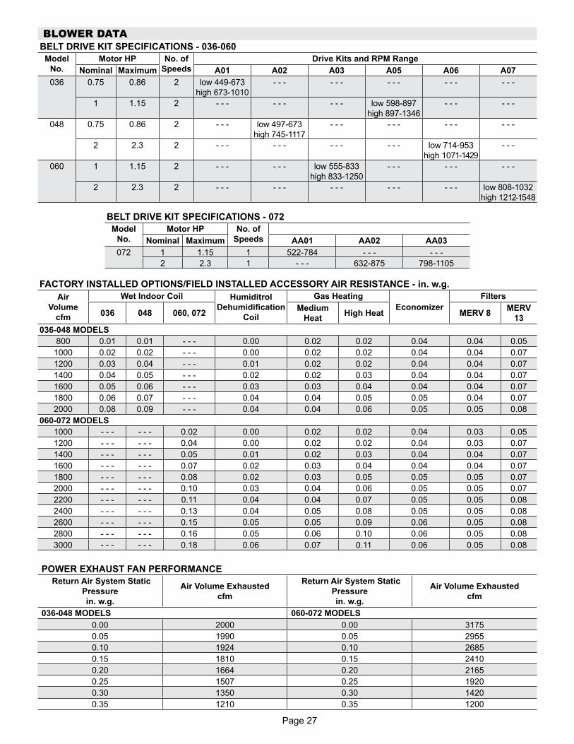
Page 27
BLOWER DATABELT DRIVE KIT SPECIFICATIONS - 036-060
Model No.
Motor HP No. of Speeds
Drive Kits and RPM RangeNominal Maximum A01 A02 A03 A05 A06 A07
036 0.75 0.86 2 low 449-673 high 673-1010
- - - - - - - - - - - - - - -
1 1.15 2 - - - - - - - - - low 598-897 high 897-1346
- - - - - -
048 0.75 0.86 2 - - - low 497-673 high 745-1117
- - - - - - - - - - - -
2 2.3 2 - - - - - - - - - - - - low 714-953 high 1071-1429
- - -
060 1 1.15 2 - - - - - - low 555-833 high 833-1250
- - - - - - - - -
2 2.3 2 - - - - - - - - - - - - - - - low 808-1032 high 1212-1548
BELT DRIVE KIT SPECIFICATIONS - 072Model
No.Motor HP No. of
SpeedsNominal Maximum AA01 AA02 AA03072 1 1.15 1 522-784 - - - - - -
2 2.3 1 - - - 632-875 798-1105
FACTORY INSTALLED OPTIONS/FIELD INSTALLED ACCESSORY AIR RESISTANCE - in. w.g.Air
Volume cfm
Wet Indoor Coil Humiditrol Dehumidification
Coil
Gas HeatingEconomizer
Filters
036 048 060, 072 Medium Heat High Heat MERV 8 MERV
13036-048 MODELS
800 0.01 0.01 - - - 0.00 0.02 0.02 0.04 0.04 0.051000 0.02 0.02 - - - 0.00 0.02 0.02 0.04 0.04 0.071200 0.03 0.04 - - - 0.01 0.02 0.02 0.04 0.04 0.071400 0.04 0.05 - - - 0.02 0.02 0.03 0.04 0.04 0.071600 0.05 0.06 - - - 0.03 0.03 0.04 0.04 0.04 0.071800 0.06 0.07 - - - 0.04 0.04 0.05 0.05 0.04 0.072000 0.08 0.09 - - - 0.04 0.04 0.06 0.05 0.05 0.08
060-072 MODELS1000 - - - - - - 0.02 0.00 0.02 0.02 0.04 0.03 0.051200 - - - - - - 0.04 0.00 0.02 0.02 0.04 0.03 0.071400 - - - - - - 0.05 0.01 0.02 0.03 0.04 0.04 0.071600 - - - - - - 0.07 0.02 0.03 0.04 0.04 0.04 0.071800 - - - - - - 0.08 0.02 0.03 0.05 0.05 0.05 0.072000 - - - - - - 0.10 0.03 0.04 0.06 0.05 0.05 0.072200 - - - - - - 0.11 0.04 0.04 0.07 0.05 0.05 0.082400 - - - - - - 0.13 0.04 0.05 0.08 0.05 0.05 0.082600 - - - - - - 0.15 0.05 0.05 0.09 0.06 0.05 0.082800 - - - - - - 0.16 0.05 0.06 0.10 0.06 0.05 0.083000 - - - - - - 0.18 0.06 0.07 0.11 0.06 0.05 0.08
POWER EXHAUST FAN PERFORMANCE Return Air System Static
Pressure in. w.g.
Air Volume Exhausted cfm
Return Air System Static Pressure in. w.g.
Air Volume Exhausted cfm
036-048 MODELS 060-072 MODELS0.00 2000 0.00 31750.05 1990 0.05 29550.10 1924 0.10 26850.15 1810 0.15 24100.20 1664 0.20 21650.25 1507 0.25 19200.30 1350 0.30 14200.35 1210 0.35 1200
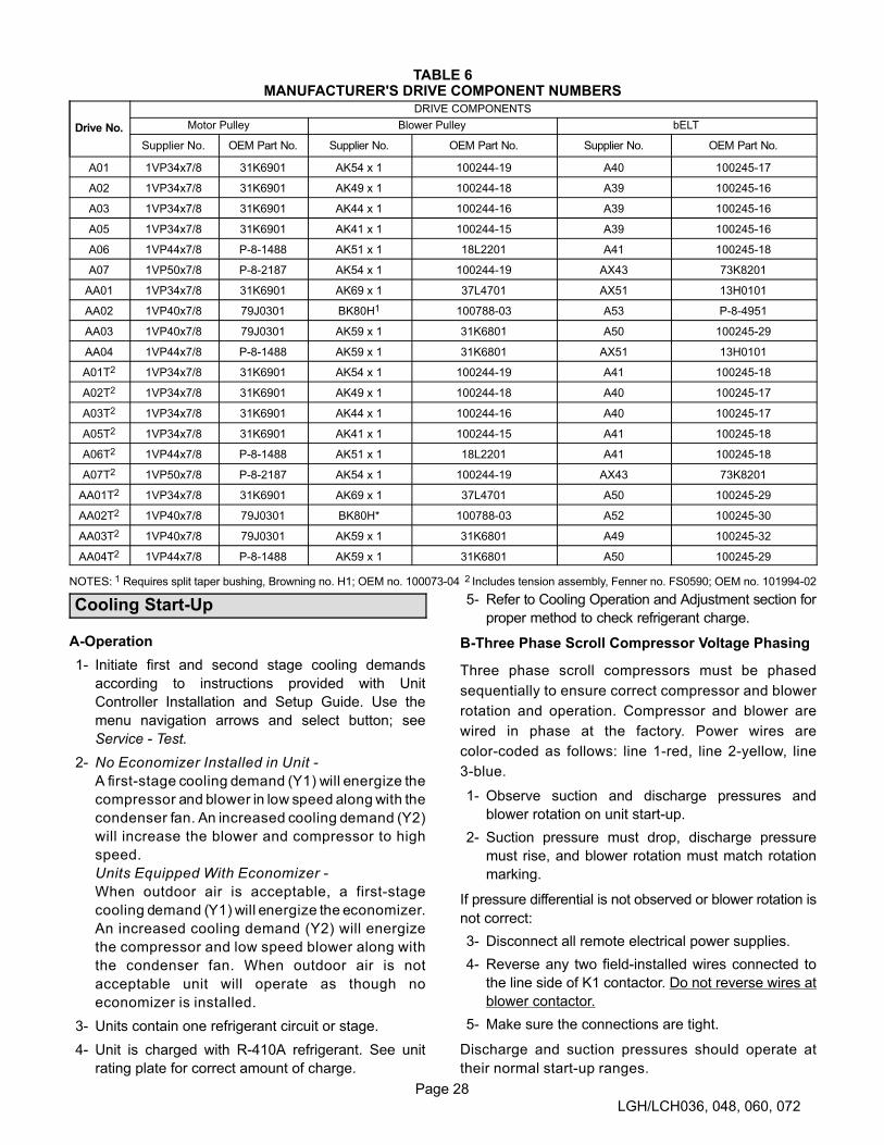
Page 28
LGH/LCH036, 048, 060, 072
TABLE 6MANUFACTURER'S DRIVE COMPONENT NUMBERS
Drive No.
DRIVE COMPONENTS
Motor Pulley Blower Pulley bELT
Supplier No. OEM Part No. Supplier No. OEM Part No. Supplier No. OEM Part No.
A01 1VP34x7/8 31K6901 AK54 x 1 100244-19 A40 100245-17
A02 1VP34x7/8 31K6901 AK49 x 1 100244-18 A39 100245-16
A03 1VP34x7/8 31K6901 AK44 x 1 100244-16 A39 100245-16
A05 1VP34x7/8 31K6901 AK41 x 1 100244-15 A39 100245-16
A06 1VP44x7/8 P-8-1488 AK51 x 1 18L2201 A41 100245-18
A07 1VP50x7/8 P-8-2187 AK54 x 1 100244-19 AX43 73K8201
AA01 1VP34x7/8 31K6901 AK69 x 1 37L4701 AX51 13H0101
AA02 1VP40x7/8 79J0301 BK80H1 100788-03 A53 P-8-4951
AA03 1VP40x7/8 79J0301 AK59 x 1 31K6801 A50 100245-29
AA04 1VP44x7/8 P-8-1488 AK59 x 1 31K6801 AX51 13H0101
A01T2 1VP34x7/8 31K6901 AK54 x 1 100244-19 A41 100245-18
A02T2 1VP34x7/8 31K6901 AK49 x 1 100244-18 A40 100245-17
A03T2 1VP34x7/8 31K6901 AK44 x 1 100244-16 A40 100245-17
A05T2 1VP34x7/8 31K6901 AK41 x 1 100244-15 A41 100245-18
A06T2 1VP44x7/8 P-8-1488 AK51 x 1 18L2201 A41 100245-18
A07T2 1VP50x7/8 P-8-2187 AK54 x 1 100244-19 AX43 73K8201
AA01T2 1VP34x7/8 31K6901 AK69 x 1 37L4701 A50 100245-29
AA02T2 1VP40x7/8 79J0301 BK80H* 100788-03 A52 100245-30
AA03T2 1VP40x7/8 79J0301 AK59 x 1 31K6801 A49 100245-32
AA04T2 1VP44x7/8 P-8-1488 AK59 x 1 31K6801 A50 100245-29
NOTES: 1 Requires split taper bushing, Browning no. H1; OEM no. 100073-04 2 Includes tension assembly, Fenner no. FS0590; OEM no. 101994-02
Cooling Start-Up
A-Operation
1- Initiate first and second stage cooling demands
according to instructions provided with Unit
Controller Installation and Setup Guide. Use the
menu navigation arrows and select button; see
Service - Test.
2- No Economizer Installed in Unit -
A first-stage cooling demand (Y1) will energize the
compressor and blower in low speed along with the
condenser fan. An increased cooling demand (Y2)
will increase the blower and compressor to high
speed.
Units Equipped With Economizer -
When outdoor air is acceptable, a first-stage
cooling demand (Y1) will energize the economizer.
An increased cooling demand (Y2) will energize
the compressor and low speed blower along with
the condenser fan. When outdoor air is not
acceptable unit will operate as though no
economizer is installed.
3- Units contain one refrigerant circuit or stage.
4- Unit is charged with R-410A refrigerant. See unit
rating plate for correct amount of charge.
5- Refer to Cooling Operation and Adjustment section for
proper method to check refrigerant charge.
B-Three Phase Scroll Compressor Voltage Phasing
Three phase scroll compressors must be phased
sequentially to ensure correct compressor and blower
rotation and operation. Compressor and blower are
wired in phase at the factory. Power wires are
color-coded as follows: line 1-red, line 2-yellow, line
3-blue.
1- Observe suction and discharge pressures and
blower rotation on unit start-up.
2- Suction pressure must drop, discharge pressure
must rise, and blower rotation must match rotation
marking.
If pressure differential is not observed or blower rotation is
not correct:
3- Disconnect all remote electrical power supplies.
4- Reverse any two field-installed wires connected to
the line side of K1 contactor. Do not reverse wires at
blower contactor.
5- Make sure the connections are tight.
Discharge and suction pressures should operate at
their normal start‐up ranges.

Page 29
LGH/LCH036, 048, 060, 072
C-Refrigerant Charge and Check - All-Aluminum Coil
WARNING-Do not exceed nameplate charge under
any condition.
This unit is factory charged and should require no further
adjustment. If the system requires additional refrigerant,
reclaim the charge, evacuate the system, and add
required nameplate charge.
NOTE - System charging is not recommended below
60�F (15�C). In temperatures below 60�F (15�C), the
charge must be weighed into the system.
If weighing facilities are not available, or to check the
charge, use the following procedure:
IMPORTANT - Charge unit in standard cooling mode
high stage only.
1- Make sure outdoor coil is clean. Attach gauge
manifolds and operate unit at full CFM in cooling mode
with economizer disabled until system stabilizes
(approximately five minutes). Make sure all outdoor air
dampers are closed.
2- Compare the normal operating pressures (see tables
7 - 13) to the pressures obtained from the gauges.
Check unit components if there are significant
differences.
3- Measure the outdoor ambient temperature and the
suction pressure. Refer to the appropriate circuit
charging curve to determine a target liquid
temperature.
Note - Pressures are listed for sea level applications.
4- Use the same thermometer to accurately measure the
liquid temperature (in the outdoor section).
� If measured liquid temperature is higher than
the target liquid temperature, add refrigerant to
the system.
� If measured liquid temperature is lower than
the target liquid temperature, recover some
refrigerant from the system.
5- Add or remove charge in increments. Allow the
system to stabilize each time refrigerant is added or
removed.
6- Continue the process until measured liquid
temperature agrees with the target liquid
temperature. Do not go below the target liquid
temperature when adjusting charge. Note that
suction pressure can change as charge is adjusted.
7- Example LGH/LCH036H: At 95°F outdoor ambient
and a measured suction pressure of 130psig, the
target liquid temperature is 98°F. For a measured
liquid temperature of 106°F, add charge in
increments until measured liquid temperature agrees
with the target liquid temperature.
TABLE 7LGH/LCH036S NORMAL OPERATING PRESSURES - ALL-ALUMINUM COIL
Outdoor Coil Entering Air Temperature
65 F 75 F 85 F 95 F 105 F 115 F
Suct(psig)
Disc(psig)
Suct(psig)
Disc(psig)
Suct(psig)
Disc(psig)
Suct(psig)
Disc(psig)
Suct(psig)
Disc(psig)
Suct(psig)
Disc(psig)
113 235 117 274 116 329 118 379 121 438 124 497
121 239 122 284 125 327 127 378 129 437 132 506
138 248 141 288 144 329 147 375 151 427 151 497
157 264 160 297 163 339 167 387 172 437 175 492
TABLE 8LGH/LCH036H NORMAL OPERATING PRESSURES - ALL-ALUMINUM COIL
Outdoor Coil Entering Air Temperature
65 F 75 F 85 F 95 F 105 F 115 F
Suct(psig)
Disc(psig)
Suct(psig)
Disc(psig)
Suct(psig)
Disc(psig)
Suct(psig)
Disc(psig)
Suct(psig)
Disc(psig)
Suct(psig)
Disc(psig)
115 242 116 283 119 328 120 382 122 444 124 535
121 245 124 284 126 329 128 379 129 447 131 528
138 255 143 294 146 340 148 389 151 441 152 515
155 267 160 305 165 349 168 399 171 454 175 514

Page 30
LGH/LCH036, 048, 060, 072
TABLE 9LGH/LCH048S NORMAL OPERATING PRESSURES - ALL-ALUMINUM COIL
Outdoor Coil Entering Air Temperature
65 F 75 F 85 F 95 F 105 F 115 F
Suct(psig)
Disc(psig)
Suct(psig)
Disc(psig)
Suct(psig)
Disc(psig)
Suct(psig)
Disc(psig)
Suct(psig)
Disc(psig)
Suct(psig)
Disc(psig)
117 249 120 287 122 330 124 381 126 435 129 493
124 253 128 291 131 332 133 386 135 441 138 499
141 272 145 306 149 345 152 393 155 448 157 515
160 300 163 332 167 367 172 415 176 465 179 520
TABLE 10LGH/LCH048H NORMAL OPERATING PRESSURES - ALL-ALUMINUM COIL
Outdoor Coil Entering Air Temperature
65 F 75 F 85 F 95 F 105 F 115 F
Suct(psig)
Disc(psig)
Suct(psig)
Disc(psig)
Suct(psig)
Disc(psig)
Suct(psig)
Disc(psig)
Suct(psig)
Disc(psig)
Suct(psig)
Disc(psig)
116 251 119 289 121 331 124 377 126 429 129 488
123 256 127 293 130 335 132 382 135 435 137 494
139 277 143 308 148 348 151 395 155 447 158 503
156 306 161 338 165 373 170 416 174 468 178 523
TABLE 11LGH/LCH060S NORMAL OPERATING PRESSURES - ALL-ALUMINUM COIL
Outdoor Coil Entering Air Temperature
65 F 75 F 85 F 95 F 105 F 115 F
Suct(psig)
Disc(psig)
Suct(psig)
Disc(psig)
Suct(psig)
Disc(psig)
Suct(psig)
Disc(psig)
Suct(psig)
Disc(psig)
Suct(psig)
Disc(psig)
114 249 116 287 119 330 121 376 123 425 127 482
122 250 124 290 127 333 129 379 132 435 135 492
140 258 143 293 145 343 148 392 151 449 154 508
158 274 162 311 166 356 169 398 173 462 175 520
TABLE 12LGH/LCH060H NORMAL OPERATING PRESSURES - ALL-ALUMINUM COIL
Outdoor Coil Entering Air Temperature
65 F 75 F 85 F 95 F 105 F 115 F
Suct(psig)
Disc(psig)
Suct(psig)
Disc(psig)
Suct(psig)
Disc(psig)
Suct(psig)
Disc(psig)
Suct(psig)
Disc(psig)
Suct(psig)
Disc(psig)
113 240 116 285 117 329 119 383 120 454 122 533
122 245 125 285 127 322 129 376 130 431 132 516
141 254 143 293 146 334 149 382 151 436 153 498
159 269 163 305 167 351 169 395 172 448 176 507
TABLE 13LGH/LCH072H NORMAL OPERATING PRESSURES - ALL-ALUMINUM COIL
Outdoor Coil Entering Air Temperature
65 F 75 F 85 F 95 F 105 F 115 F
Suct(psig)
Disc(psig)
Suct(psig)
Disc(psig)
Suct(psig)
Disc(psig)
Suct(psig)
Disc(psig)
Suct(psig)
Disc(psig)
Suct(psig)
Disc(psig)
113 261 115 300 116 347 118 402 119 492 123 512
122 266 124 307 126 349 126 402 128 467 132 518
140 277 143 316 145 360 147 411 149 472 151 540
159 291 161 329 164 375 168 423 172 478 174 537

Page 31
LGH/LCH036, 048, 060, 072
LGH/LCH036S CHARGING CURVE - ALL-ALUMINUM COIL
60
70
80
90
100
110
120
130
110 120 130 140 150 160 170 180
Outdoor Temperature (°F)
Suction Pressure (psig)
105°
95°
115°
85°
75°
65°
60
70
80
90
100
110
120
130
110 120 130 140 150 160
Outdoor Temperature (°F)
170 180Suction Pressure (psig)
105°
95°
115°
85°
75°
65°
LGH/LCH036H CHARGING CURVE - ALL-ALUMINUM COIL
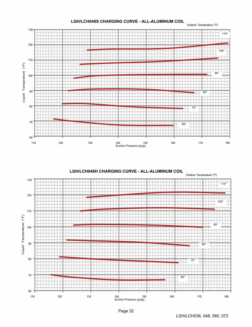
Page 32
LGH/LCH036, 048, 060, 072
LGH/LCH048S CHARGING CURVE - ALL-ALUMINUM COIL
Suction Pressure (psig)
60
70
80
90
100
110
120
130
110 120 130 140 150 160
Outdoor Temperature (°F)
170 180
105°
95°
115°
85°
75°
65°
LGH/LCH048H CHARGING CURVE - ALL-ALUMINUM COIL
Suction Pressure (psig)
60
70
80
90
100
110
120
130
110 120 130 140 150 160
Outdoor Temperature (°F)
170 180
105°
95°
115°
85°
75°
65°
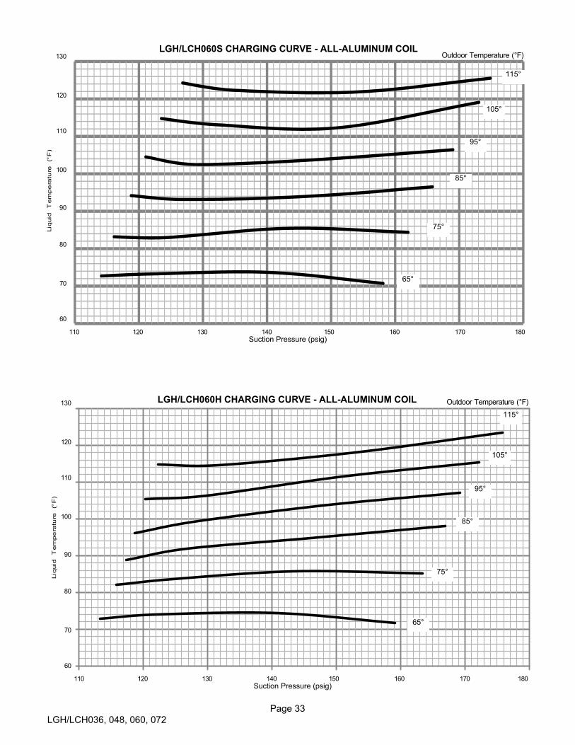
Page 33
LGH/LCH036, 048, 060, 072
LGH/LCH060S CHARGING CURVE - ALL-ALUMINUM COIL
60
70
80
90
100
110
120
130
110 120 130 140 150 160
Outdoor Temperature (°F)
170 180Suction Pressure (psig)
105°
95°
115°
85°
75°
65°
60
70
80
90
100
110
120
130
110 120 130 140 150 160
Outdoor Temperature (°F)
170 180Suction Pressure (psig)
105°
95°
115°
85°
75°
65°
LGH/LCH060H CHARGING CURVE - ALL-ALUMINUM COIL

Page 34
LGH/LCH036, 048, 060, 072
LGH/LCH072H CHARGING CURVE - ALL-ALUMINUM COIL
Suction Pressure (psig)
60
70
80
90
100
110
120
130
110 120 130 140 150 160
Outdoor Temperature (°F)
170 180
105°
95°
115°
85°
75°
65°

Page 35
LGH/LCH036, 048, 060, 072
C-Refrigerant Charge and Check - Fin/Tube Coil
WARNING-Do not exceed nameplate charge underany condition.
This unit is factory charged and should require no further
adjustment. If the system requires additional refrigerant,
reclaim the charge, evacuate the system, and add
required nameplate charge.
NOTE - System charging is not recommended below
60°F (15°C). In temperatures below 60°F (15°C) , the
charge must be weighed into the system.
If weighing facilities are not available, or to check the
charge, use the following procedure:
1- Attach gauge manifolds and operate unit in cooling
mode on HIGH SPEED with economizer disabled
until system stabilizes (approximately five minutes).
Make sure outdoor air dampers are closed.
2- Use a thermometer to accurately measure the
outdoor ambient temperature.
3- Apply the outdoor temperature to tables 14 through
27 to determine normal operating pressures.
Pressures are listed for sea level applications at 80°F
dry bulb and 67°F wet bulb return air.
4- Compare the normal operating pressures to the
pressures obtained from the gauges. Minor
variations in these pressures may be expected due to
differences in installations. Significant differences
could mean that the system is not properly charged
or that a problem exists with some component in the
system. Correct any system problems before
proceeding.
5- If discharge pressure is high, remove refrigerant from
the system. If discharge pressure is low, add
refrigerant to the system.
� Add or remove charge in increments.
� Allow the system to stabilize each time
refrigerant is added or removed.
6- Use the following approach method along with the
normal operating pressures to confirm readings.
TABLE 14LG/LC 036S NORMAL OPERATING PRESSURES
Outdoor CoilEntering Air Temp
Discharge+10 psig
Suction + 5psig
65� F 267 138
75� F 305 140
85� F 350 142
95� F 398 146
105� F 451 147
115� F 507 150
TABLE 15LG/LC 036S REHEAT NORMAL OPERATING
PRESSURES
Outdoor CoilEntering Air Temp
Discharge+10 psig
Suction + 5psig
65� F 261 138
75� F 300 141
85� F 342 144
95� F 387 148
105� F 437 150
115� F 490 153
TABLE 16LG/LC 036H NORMAL OPERATING PRESSURES
Outdoor CoilEntering Air Temp
Discharge+10 psig
Suction + 5psig
65� F 262 142
75� F 293 145
85� F 345 147
95� F 389 149
105� F 439 152
115� F 493 155
TABLE 17LG/LC 036H REHEAT NORMAL OPERATING
PRESSURES
Outdoor CoilEntering Air Temp
Discharge+10 psig
Suction + 5psig
65� F 262 139
75� F 299 141
85� F 342 144
95� F 388 147
105� F 437 150
115� F 491 153
TABLE 18LG/LC 048S NORMAL OPERATING PRESSURES
Outdoor CoilEntering Air Temp
Discharge+10 psig
Suction + 5psig
65� F 259 129
75� F 299 138
85� F 343 146
95� F 390 148
105� F 442 157
115� F 497 160
TABLE 19LG/LC 048S REHEAT NORMAL OPERATING
PRESSURES
Outdoor CoilEntering Air Temp
Discharge+10 psig
Suction + 5psig
65� F 259 139
75� F 298 143
85� F 340 145
95� F 388 148
105� F 439 151
115� F 495 154

Page 36
LGH/LCH036, 048, 060, 072
TABLE 20LG/LC 048H NORMAL OPERATING PRESSURES
Outdoor CoilEntering Air Temp
Discharge+10 psig
Suction + 5psig
65� F 256 122
75� F 299 132
85� F 342 139
95� F 388 145
105� F 437 150
115� F 493 153
TABLE 21LG/LC 048H REHEAT NORMAL OPERATING
PRESSURES
Outdoor CoilEntering Air Temp
Discharge+10 psig
Suction + 5psig
65� F 261 138
75� F 299 142
85� F 342 144
95� F 389 147
105� F 441 150
115� F 497 153
TABLE 22LG/LC 060S NORMAL OPERATING PRESSURES
Outdoor CoilEntering Air Temp
Discharge+10 psig
Suction + 5psig
65� F 264 136
75� F 303 138
85� F 346 140
95� F 395 142
105� F 445 145
115� F 500 148
TABLE 23LG/LC 060S REHEAT NORMAL OPERATING
PRESSURES
Outdoor CoilEntering Air Temp
Discharge+10 psig
Suction + 5psig
65� F 267 135
75� F 307 137
85� F 350 139
95� F 399 142
105� F 451 144
115� F 507 147
TABLE 24LG/LC 060H NORMAL OPERATING PRESSURES
Outdoor CoilEntering Air Temp
Discharge+10 psig
Suction + 5psig
65� F 253 136
75� F 291 137
85� F 334 139
95� F 380 142
105� F 427 145
115� F 479 148
TABLE 25LG/LC 060H REHEAT NORMAL OPERATING
PRESSURES
Outdoor CoilEntering Air Temp
Discharge+10 psig
Suction + 5psig
65� F 256 136
75� F 295 138
85� F 337 140
95� F 384 143
105� F 432 146
115� F 488 147
TABLE 26LG/LC 072H NORMAL OPERATING PRESSURES
Outdoor CoilEntering Air Temp
Discharge+10 psig
Suction + 5psig
65� F 271 136
75� F 312 139
85� F 357 141
95� F 405 144
105� F 458 147
115� F 515 151
TABLE 27LG/LC 072H REHEAT NORMAL OPERATING
PRESSURES
Outdoor CoilEntering Air Temp
Discharge+10 psig
Suction + 5psig
65� F 272 137
75� F 312 139
85� F 356 140
95� F 403 142
105� F 453 145
115� F 507 148
D-Charge Verification - Approach Method - AHRI
TESTING (Fin/Tube Coil Continued)
1- Using the same thermometer, compare liquid
temperature to outdoor ambient temperature.
Approach Temperature = Liquid temperature (at
condenser outlet) minus ambient temperature.
2- Approach temperature should match values in table
28. An approach temperature greater than value
shown indicates an undercharge. An approach
temperature less than value shown indicates an
overcharge.
3- The approach method is not valid for grossly over or
undercharged systems. Use tables 14 through 27 as
a guide for typical operating pressures.

Page 37
LGH/LCH036, 048, 060, 072
TABLE 28APPROACH TEMPERATURE
LGH/LCH Unit Liquid Temp. Minus Ambient Temp.
036S & H Std.036S & H Reheat048H Std.060S & H Reheat060H Std.072H Std.
6°F + 1 (3.3°C + 0.5)
048H Reheat072H Reheat
7°F + 1 (3.9°C + 0.5)
048S Std.060S Std.
8°F + 1 (4.4°C + 0.5)
048S Reheat 9°F + 1 (5.0°C + 0.5)
E-Compressor Controls
See unit wiring diagram to determine which controls are
used on each unit. Optional controls are identified on
wiring diagrams by arrows at junction points.
1- High Pressure Switch (S4)
The compressor circuit is protected by a high
pressure switch which opens at 640 psig + 10 psig
(4413 kPa + 70 kPa) and automatically resets at 475
psig + 20 psig (3275kPa + 138 kPa).
2- Low Pressure Switch (S87)
The compressor circuit is protected by a loss of
charge switch. Switch opens at 40 psig + 5 psig (276
+ 34 kPa) and automatically resets at 90 psig + 5
psig (621 kPa + 34 kPa).
3- Freezestat (S49)
The compressor is protected by a freezestat located
on the indoor coil. The freezestat opens at 29�F+3
(-2�C+2) and closes at 58�F+4 (14�C+2).
4- Compressor Crankcase Heater (HR1)
Crankcase heater must be energized at all times to
prevent compressor damage due to refrigerant
migration. Energize crankcase heater 24 hours before
unit start-up by setting thermostat so that there is no
cooling demand (to prevent compressor from cycling)
and apply power to unit.
5- Low Ambient Pressure Switch (S11)
Switch maintains adequate discharge pressure by
de-energizing condenser fan when liquid pressure
falls below 240 psig +10 (1655 kPa+69). S11 is
installed in the liquid line. Switch closes to energize
condenser fan when pressure rises to 450 psig +10
(3103kPa + 69).
6- Discharge Line Thermostat (S40)
3 through 5 Ton Units Only
Switch opens when discharge line temperature
reaches 94�F+5 (34�C+3) and closes when
temperature falls below 74�F+5 (23�C+3). Prevents
crankcase heater operation in warm weather.
7- High Ambient Pressure Switch (S16)
Switch improves high ambient operation by
activating the TXV assist circuit. Switch closes at
550psig + 10 (3792kPa + 70kPa) and automatically
resets at 400 PSIG (2758kPa + 70kPa).
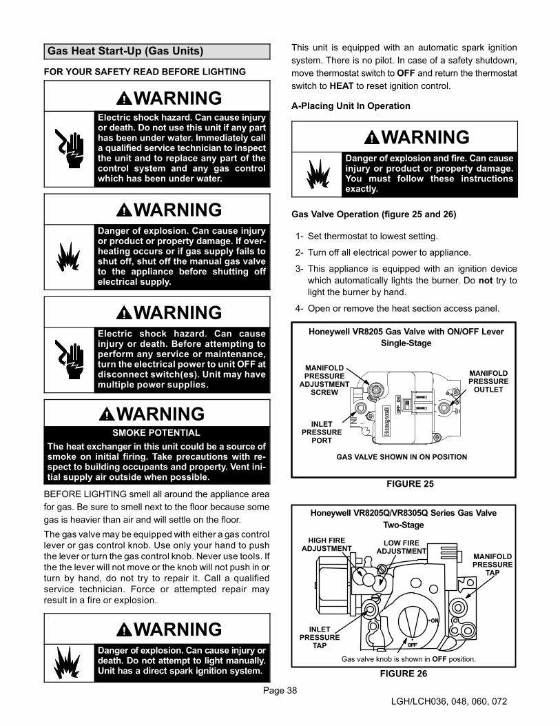
Page 38
LGH/LCH036, 048, 060, 072
Gas Heat Start-Up (Gas Units)
FOR YOUR SAFETY READ BEFORE LIGHTING
WARNINGElectric shock hazard. Can cause injuryor death. Do not use this unit if any parthas been under water. Immediately calla qualified service technician to inspectthe unit and to replace any part of thecontrol system and any gas controlwhich has been under water.
WARNINGDanger of explosion. Can cause injuryor product or property damage. If overheating occurs or if gas supply fails toshut off, shut off the manual gas valveto the appliance before shutting offelectrical supply.
WARNINGElectric shock hazard. Can causeinjury or death. Before attempting toperform any service or maintenance,turn the electrical power to unit OFF atdisconnect switch(es). Unit may havemultiple power supplies.
WARNINGSMOKE POTENTIAL
The heat exchanger in this unit could be a source ofsmoke on initial firing. Take precautions with respect to building occupants and property. Vent initial supply air outside when possible.
BEFORE LIGHTING smell all around the appliance area
for gas. Be sure to smell next to the floor because some
gas is heavier than air and will settle on the floor.
The gas valve may be equipped with either a gas control
lever or gas control knob. Use only your hand to push
the lever or turn the gas control knob. Never use tools. If
the the lever will not move or the knob will not push in or
turn by hand, do not try to repair it. Call a qualified
service technician. Force or attempted repair may
result in a fire or explosion.
WARNINGDanger of explosion. Can cause injury ordeath. Do not attempt to light manually.Unit has a direct spark ignition system.
This unit is equipped with an automatic spark ignition
system. There is no pilot. In case of a safety shutdown,
move thermostat switch to OFF and return the thermostat
switch to HEAT to reset ignition control.
A-Placing Unit In Operation
WARNINGDanger of explosion and fire. Can causeinjury or product or property damage.You must follow these instructionsexactly.
Gas Valve Operation (figure 25 and 26)
1- Set thermostat to lowest setting.
2- Turn off all electrical power to appliance.
3- This appliance is equipped with an ignition device
which automatically lights the burner. Do not try to
light the burner by hand.
4- Open or remove the heat section access panel.
GAS VALVE SHOWN IN ON POSITION
Honeywell VR8205 Gas Valve with ON/OFF Lever
Single-Stage
MANIFOLDPRESSURE
OUTLET
INLETPRESSURE
PORT
MANIFOLDPRESSURE
ADJUSTMENTSCREW
FIGURE 25
Honeywell VR8205Q/VR8305Q Series Gas Valve
Two-Stage
Gas valve knob is shown in OFF position.
FIGURE 26
LOW FIREADJUSTMENT
HIGH FIREADJUSTMENT
INLETPRESSURE
TAP
MANIFOLDPRESSURE
TAP

Page 39
LGH/LCH036, 048, 060, 072
5- Honeywell VR8205 Gas Valve with ON/OFF Lever -
Switch gas valve lever to OFF. See figure 25.
Honeywell VR8205/8305 Gas Valve with Knob - Turn
knob on gas valve clockwise to OFF. Do not force.
See figure 26.
6- Wait five (5) minutes to clear out any gas. If you then
smell gas, STOP! Immediately call your
gas supplier from a neighbor's phone. Follow the gas
supplier's instructions. If you do not smell gas, go to
the next step.
7- Honeywell VR8205 Gas Valve with ON/OFF Lever -
Switch gas valve lever to ON. See figure 25.
Honeywell VR8205/VR8305 Gas Valve with Knob -
Turn knob on gas valve counterclockwise to ON.
Do not force. See figure 26.
8- Close or replace the heat section access panel.
9- Turn on all electrical power to appliance.
10- Set thermostat to desired setting.
NOTE - When unit is initially started, steps 1 through 9
may need to be repeated to purge air from gas line.
11- The ignition sequence will start.
12- If the furnace does not light the first time (gas line not
fully purged), it will attempt up to two more ignitions
before locking out.
13- If lockout occurs, repeat steps 1 through 10.
14- If the appliance will not operate, follow the
instructions “Turning Off Gas to Appliance” and call
your service technician or gas supplier.
Turning Off Gas to Unit
1- If using an electromechanical thermostat, set to the
lowest setting.
2- Before performing any service, turn off all electrical
power to the appliance.
3- Open or remove the heat section access panel.
4- Honeywell VR8205 Gas Valve with ON/OFF Lever -
Switch gas valve lever to OFF.
Honeywell VR8205/VR8305 Gas Valve with Knob -
Turn knob on gas valve clockwise to OFF. Do not
force.
5- Close or replace the heat section access panel.
WARNINGDanger of explosion. Can cause injury ordeath. Do not attempt to light manually.Unit has a direct spark ignition system.
Heating Operation and Adjustments
(Gas Units)
A-Heating Sequence of Operation
1- On a heating demand the combustion air inducer
starts immediately.
2- Combustion air pressure switch proves inducer
operation. After a 30-second pre-purge, power is
allowed to ignition control. Switch is factory set and
requires no adjustment.
3- Spark ignitor energizes and gas valve solenoid
opens.
4- Spark ignites gas, ignition sensor proves the flame
and combustion continues.
5- If flame is not detected after 8 seconds, the ignition
control will repeat steps 3 and 4 two more times. The
ignition control will wait 5 minutes before the ignition
attempt recycles.
B-Ignition Control Diagnostic LED's
TABLE 29IGNITION CONTROL HEARTBEAT LED STATUS
LEDFlashes
Indicates
Steady Off No power or control hardware fault.
Steady On Power applied. Control OK.
3 Flashes Ignition lockout from too many trials.
4 FlashesIgnition lockout from too many flamelosses within single call for heat.
5 Flashes Control hardware fault detected.
C-Limit Controls
Limit controls are factory-set and are not adjustable. The
primary limit is located to the right of the combustion air
inducer. See figure 35.
D-Heating Adjustment
Main burners are factory-set and do not require adjustment.
The following manifold pressures are listed on the gas valve.
Natural Gas Units - Low Fire - 1.7” w.c.
Natural Gas Units - High Fire - 3.5” w.c.
LP Gas Units - Low Fire - 5.1” w.c.
LP Gas Units - High Fire - 10.5” w.c.
Electric Heat Start-Up (LCH Units)
Optional electric heat will stage on and cycle with
thermostat demand. See electric heat wiring diagram on
unit for sequence of operation.

Page 40
LGH/LCH036, 048, 060, 072
VCB Start-Up
Units equipped with an A184 ventilation control board
(VCB) allow the installer to enter the design-specified
supply air CFM into the Unit Controller. In addition, the
outdoor air flow (minimum damper position) can be
entered. These air volumes are typically adjusted by
taking measurements and adjusting settings.
The factory-installed VCB option is available on units
equipped with a direct drive blower and an economizer.
The VCB is located on the Unit Controller. See figure 27.
The economizer is equipped with a PT5 pressure
transducer which provides feedback for damper
minimum position. See figure 28 for PT5 location. Refer to
the economizer installation instructions and Unit
Controller manual for additional economizer set-up.
Note - Modulation of dampers for free cooling does not
change. The outdoor air flow setting determines minimum
damper position instead of adjusting a potentiometer.
ADesign Specifications
Use table 30 to fill in the field-provided,
design-specified supply air CFM and minimum required
outdoor/fresh air CFM.
TABLE 30
FIELD-PROVIDED DESIGN SPECIFICATIONS
Supply Air CFM
Heating CFM
Cooling High CFM
Cooling Low CFM
Ventilation CFM
Economizer Minimum Position
Outdoor Airflow CFM
A184 VENTILATION CONTROL BOARD
VCB BOARD
FIGURE 27
UNIT CONTROLLER
PT5 PRESSURE TRANSDUCER
PRESSURETRANSDUCER
FIGURE 28
ECONOMIZER
BEnter Supply Air CFM Into Unit Controller
Use the following menu path to enter each supply air CFM
into the Unit Controller. Make sure supply air CFM is
within limitations shown in table 31. Refer to the Unit
Controller manual provided with unit.
CAUTIONThe BLOWER CALIBRATION process starts the in
door blower at operational speeds and moves the
economizer damper blades. Before starting this pro
cess, replace any access panels and close all unit
doors except compressor compartment door.
Settings - Control - MSAV - Blower - Heating CFM
(enter value) - Cooling High CFM (enter value) -
Cooling Low CFM (enter value) - Ventilation CFM
(enter value) - Start Blower To Calibrate (yes/no).
Select YES to start calibration. The blower calibration
status is displayed as a % complete. Upon successful
completion, the Unit Controller will display
CALIBRATE COMPLETE, save the entered values
and revert to the MSAV menu.
Select NO and the Unit Controller will display an option to
SAVE SETTINGS (YES / NO). Select YES to save
settings without performing the calibration process.
Select NO to exit the menu without saving entered values.
The display reverts to MSAV menu with either selection.

Page 41
LGH/LCH036, 048, 060, 072
TABLE 31
MINIMUM / MAXIMUM CFM
UNIT SIZE 036 048 060
Cooling High Speed &
Heating Maximum
(480 CFM/ton)
1440 1920 2400
Cooling High Speed
Minimum (280 CFM/ton)840 1120 1400
Cooling Low Minimum CFM
(220 CFM/ton)660 880 1100
Ventilation Minimum CFM
(150 CFM/ton)450 600 750
Standard Gas Heat Minim
um CFM (S,W)970 970 970
Medium Gas Heat Minimum
CFM (M, Q, U, Y)1120 1120 1120
High Gas Heat Minimum
CFM (H, T, X, Z)1310 1310 1310
Electric Heat minimum CFM 1080 1280 1600
Outdoor Airflow Maximum
CFM450 600 750
CEnter Outdoor Airflow Design Specifications Into
Unit Controller
Use the following menu path to enter the outdoor airflow
CFM (replaces minimum damper position set point) into
the Unit Controller. Make sure outdoor airflow CFM is
within limitations shown in table 31. Refer to the Unit
Controller manual provided with unit.
Settings Control MSAV Damper Outdoor Airflow
(enter value) Save Settings (yes / no)
After a YES or NO selection, display reverts back to
MSAV menu.
DOperation
1- After calibration, the indoor blower will supply the
CFM specified based on the thermostat demand
signal received by the Unit Controller:
G – Ventilation CFM
W – Heating CFM
Y1 – Cooling Low CFM
Y2 – Cooling High CFM
2- The Unit Controller, using input from PT5 and the
entered outdoor air flow CFM, will open the fresh
air dampers to minimum position. In addition, the
Unit Controller must have an occupied (OCP)
thermostat demand.

Page 42
LGH/LCH036, 048, 060, 072
SCR Electric Heat Controller (LCH Units)
Optional factory-installed SCR (A38) will provide small
amounts of power to the electric heat elements to
efficiently maintain warm duct air temperatures when
there is no heating demand. The SCR maintains duct
air temperature based on input from a field-provided
and installed thermostat (A104) and duct sensor
(RT20). SCR is located in the compressor section on
the left wall. Use only with a thermostat or Novar
control system.
Use the instructions provided with the thermostat to set
DIP switches as follows: S1 On, S2 Off, S3 Off. Use the
instructions provided with the duct sensor to install sensor
away from electric element radiant heat and in a location
where discharge air is a mixed average temperature.
Once power is supplied to unit, zero SCR as follows:
1- Adjust thermostat (A104) to minimum position.
2- Use a small screwdriver to slowly turn the ZERO
potentiometer on the SCR until the LED turns solid red.
3- Very slowly adjust the potentiometer the opposite
direction until the LED turns off.
Hot Gas Reheat Start-Up And Operation
General
Hot gas reheat units provide a dehumidifying mode of
operation. These units contain a reheat coil adjacent to
and downstream of the evaporator coil. Reheat coil
solenoid valve, L14, routes hot discharge gas from the
compressor to the reheat coil. Return air pulled across
the evaporator coil is cooled and dehumidified; the
reheat coil adds heat to supply air. See figure 29 for
reheat refrigerant routing and figure 30 for standard
cooling refrigerant routing.
L14 Reheat Coil Solenoid Valve
When Unit Controller input (Unit Controller J298-5 or
J299-8) indicates room conditions require
dehumidification, L14 reheat valve is energized (Unit
Controller P269-3) and refrigerant is routed to the
reheat coil.
Reheat Setpoint
Reheat is factory-set to energize when indoor relative
humidity rises above 60% (default). The reheat setpoint
can be adjusted by changing Unit Controller Settings -
Control menu. A setting of 100% will operate reheat from
an energy management system digital output. The reheat
setpoint can also be adjusted using an optional Network
Control Panel (NCP).
Reheat will terminate when the indoor relative humidity
falls 3% (57% default) or the digital output de-energizes.
The reheat deadband can be adjusted at Settings -
Control menu.
REHEAT MODE REFRIGERANT ROUTING
REHEATCOIL
EVAPORATOR
REHEATVALVE
RETURNAIR
CONDENSERCOIL
OUTDOORAIR
COMPRESSOR
SUPPLYAIR
CHECKVALVE
EXPANSIONVALVE
FIGURE 29
COIL

Page 43
LGH/LCH036, 048, 060, 072
COOLING MODE REFRIGERANT ROUTING
REHEATCOIL
EVAPORATOR
REHEATVALVE
RETURNAIR
CONDENSERCOIL
OUTDOORAIR
COMPRESSOR
SUPPLYAIR
CHECKVALVE
EXPANSIONVALVE
FIGURE 30
COIL
Check-Out
Test reheat operation using the following procedure.
1- Make sure reheat is wired as shown in wiring section.
2- Make sure unit is in local thermostat mode.
3- Select Unit Controller Service - Test.
The blower and compressor 1 (reheat) should be
operating. Reheat mode will be appear on the Unit
Controller display.
4- Deselect Unit Controller Service - Test.
Compressor 1 (reheat) and blower should de-energize.
Default Reheat Operation
During reheat mode free cooling is locked out.
No Y1 demand but a call for dehumidification:
Compressor is operating, blower is on, and the reheat
valve is energized.
Y1 demand:
Compressor is operating, blower is on, and the reheat
valve is energized.
Y2 demand:
Compressor is operating, blower is on, and the reheat
valve is de-energized.
Service
The unit should be inspected once a year by a qualified
service technician.
CAUTIONLabel all wires prior to disconnection when servicing controls. Wiring errors can cause improper anddangerous operation. Verify proper operation afterservicing.
WARNINGThe State of California has determined that thisproduct may contain or produce a chemical orchemicals, in very low doses, which may cause serious illness or death. It may also cause cancer,birth defects, or reproductive harm.
A-Filters
Units are equipped with temporary filters which must be
replaced prior to building occupation. See table 32 for
correct filter size. Refer to local codes or appropriate
jurisdiction for approved filters.
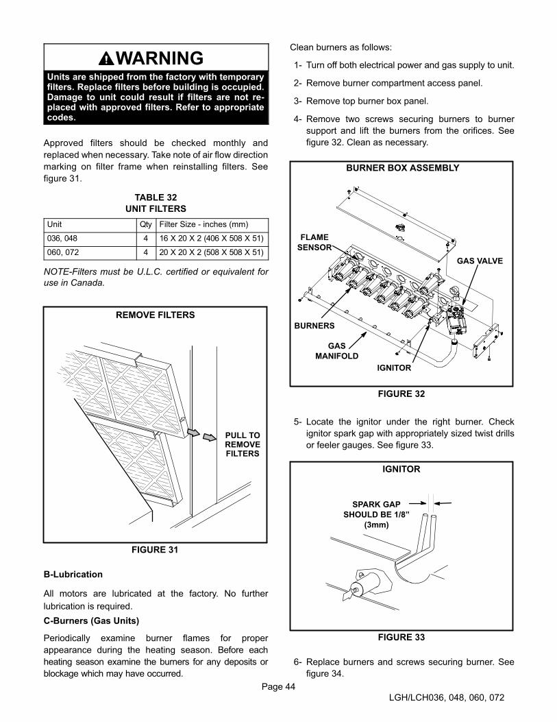
Page 44
LGH/LCH036, 048, 060, 072
WARNINGUnits are shipped from the factory with temporaryfilters. Replace filters before building is occupied.Damage to unit could result if filters are not replaced with approved filters. Refer to appropriatecodes.
Approved filters should be checked monthly and
replaced when necessary. Take note of air flow direction
marking on filter frame when reinstalling filters. See
figure 31.
TABLE 32
UNIT FILTERS
Unit Qty Filter Size - inches (mm)
036, 048 4 16 X 20 X 2 (406 X 508 X 51)
060, 072 4 20 X 20 X 2 (508 X 508 X 51)
NOTE-Filters must be U.L.C. certified or equivalent for
use in Canada.
FIGURE 31
REMOVE FILTERS
PULL TOREMOVEFILTERS
B-Lubrication
All motors are lubricated at the factory. No further
lubrication is required.
C-Burners (Gas Units)
Periodically examine burner flames for proper
appearance during the heating season. Before each
heating season examine the burners for any deposits or
blockage which may have occurred.
Clean burners as follows:
1- Turn off both electrical power and gas supply to unit.
2- Remove burner compartment access panel.
3- Remove top burner box panel.
4- Remove two screws securing burners to burner
support and lift the burners from the orifices. See
figure 32. Clean as necessary.
FIGURE 32
BURNER BOX ASSEMBLY
GAS VALVE
GAS
MANIFOLD
FLAME
SENSOR
BURNERS
IGNITOR
5- Locate the ignitor under the right burner. Check
ignitor spark gap with appropriately sized twist drills
or feeler gauges. See figure 33.
FIGURE 33
IGNITOR
SPARK GAP
SHOULD BE 1/8”
(3mm)
6- Replace burners and screws securing burner. See
figure 34.

Page 45
LGH/LCH036, 048, 060, 072
WARNINGDanger of explosion. Can cause injury ordeath. Do not overtighten main burnermounting screws. Snug tighten only.
7- Replace access panel.
8- Restore electrical power and gas supply. Follow
lighting instructions attached to unit and use
inspection port in access panel to check flame.
FIGURE 34
BURNER ORIENTATION
150,000 BTUH - 7 BURNERS
105,000 BTUH - 5 BURNERS
65,000 BTUH - 3 BURNERS
SENSOR IGNITOR
SENSOR IGNITOR
SENSOR IGNITOR
D-Combustion Air Inducer (Gas Units)
A combustion air proving switch checks combustion air
inducer operation before allowing power to the gas
controller. Gas controller will not operate if inducer is
obstructed.
Under normal operating conditions, the combustion air
inducer wheel should be checked and cleaned prior to the
heating season. However, it should be examined
periodically during the heating season to establish an
ideal cleaning schedule.
Clean combustion air inducer as follows:
1- Shut off power supply and gas to unit.
2- Remove the mullion on the right side of the heat
section.
3- Disconnect pressure switch air tubing from
combustion air inducer port.
4- Remove and retain screws securing combustion
air inducer to flue box. Remove vent connector.
See figure 35.
5- Clean inducer wheel blades with a small brush and
wipe off any dust from housing. Take care not to
damage exposed fan blades. Clean accumulated
dust from front of flue box cover.
HEAT EXCHANGER ASSEMBLY
FIGURE 35
BURNER
COMBUSTIONAIR INDUCER
VENTCONNECTOR
GAS VALVE
HEATEXCHANGER
TUBE
PRIMARYLIMIT
ROLLOUTSWITCH
FLUE BOXCOVER
6- Return combustion air inducer motor and vent
connector to original location and secure with
retained screws. It is recommended that gaskets be
replaced during reassembly.
7- Replace mullion.
8- Clean combustion air inlet louvers on heat access
panel using a small brush.
E-Flue Box (Gas Units)
Remove flue box cover only when necessary for
equipment repair. Clean inside of flue box cover and heat
exchanger tubes with a wire brush when flue box cover
has to be removed. Install a new flue box cover gasket
and replace cover. Make sure edges around flue box
cover are tightly sealed.
F-Evaporator Coil
Inspect and clean coil at beginning of each cooling season.
Clean using mild detergent or commercial coil cleaner.
Flush coil and condensate drain with water taking care not
to get insulation, filters and return air ducts wet.

Page 46
LGH/LCH036, 048, 060, 072
G-Condenser Coil
All-Aluminum Coils -
Clean condenser coil annually with water and inspect
monthly during the cooling season.
Clean the all-aluminum coil by spraying the coil steadily
and uniformly from top to bottom. Do not exceed 900 psi
or a 45� angle; nozzle must be at least 12 inches from the
coil face. Take care not to fracture the braze between the
fins and refrigerant tubes. Reduce pressure and work
cautiously to prevent damage.
Fin/Tube Coils -
Clean condenser coil annually with detergent or
commercial coil cleaner and inspect monthly during the
cooling season.
Condenser coils are made of single and two formed slabs.
On units with two slabs, dirt and debris may become
trapped between the slabs. To clean between slabs,
carefully separate coil slabs and wash them thoroughly.
See figure 36. Flush coils with water following cleaning.
Note - Remove all screws and gaskets prior to cleaning
procedure and replace upon completion.
H-Supply Air Blower Wheel
Annually inspect supply air blower wheel for accumulated
dirt or dust. Turn off power before attempting to remove
access panel or to clean blower wheel.
TOP VIEW
CONDENSERCOILS
BLOWER
CONDENSER ACCESS PANEL
FIGURE 36
ENDPLATE IS SECUREDTO MULLION
1- Remove unit top panel and condenser section access
panel.
2- Remove screws securing coil end plate to mullion.
3- Remove wire ties connecting coils slabs and separate
slabs 3-4” (76-102mm).
4- Clean coils with detergent or commercial coil cleaner.
5- Rinse thoroughly with water and reassemble. Use
field-provided wire ties to connect coil slabs.
CLEAN CONDENSER COIL - UNITS WITH FIN/TUBE COILS
SUPPLYAIR


