INSTALLATION MANUAL
Fan coil units
Cover Cover
Type numbers
FWC06B7TV1B FWC07B7TV1B FWC08B7TV1B FWC09B7TV1B
FWC06B7FV1B FWC07B7FV1B FWC08B7FV1B FWC09B7FV1B
Dai
kin
Eu
rop
e N
.V.
CE -
DECL
ARAT
ION-
OF-C
ONFO
RMIT
YCE
- KO
NFOR
MIT
ÄTSE
RKLÄ
RUNG
CE -
DECL
ARAT
ION-
DE-C
ONFO
RMIT
ECE
- CO
NFOR
MIT
EITS
VERK
LARI
NG
CE -
DECL
ARAC
ION-
DE-C
ONFO
RMID
ADCE
- DI
CHIA
RAZI
ONE-
DI-C
ONFO
RMIT
ACE
- ¢H
§ø™H
™YM
MOP
ºø™H
™
CE -
DECL
ARAÇ
ÃO-D
E-CO
NFOR
MID
ADE
СЕ -
ЗАЯВ
ЛЕНИ
Е-О
-СО
ОТВ
ЕТСТ
ВИИ
CE -
OPFY
LDEL
SESE
RKLÆ
RING
CE -
FÖRS
ÄKRA
N-OM
-ÖVE
RENS
TÄMM
ELSE
CE -
ERKL
ÆRI
NG O
M-S
AMSV
ARCE
- IL
MOI
TUS-
YHDE
NMUK
AISU
UDES
TACE
- PR
OHL
ÁŠEN
Í-O-S
HODĚ
CE -
IZJA
VA-O
-USK
LAĐE
NOST
ICE
- M
EGFE
LELŐ
SÉG
I-NYI
LATK
OZA
TCE
- DE
KLAR
ACJA
-ZG
ODN
OŚC
ICE
- DE
CLAR
AŢIE
-DE-
CONF
ORM
ITAT
E
CE -
IZJA
VA O
SKL
ADNO
STI
CE -
VAST
AVUS
DEKL
ARAT
SIO
ON
CE -
ДЕКЛ
АРАЦ
ИЯ-З
А-СЪ
ОТВЕ
ТСТВ
ИЕ
CE -
ATIT
IKTI
ES-D
EKLA
RACI
JACE
- AT
BILS
TĪBA
S-DE
KLAR
ĀCIJ
ACE
- VY
HLÁS
ENIE
-ZHO
DYCE
- UY
UMLU
LUK-
BİLD
İRİS
İ
01ar
e in
confo
rmity
with
the
follo
wing
sta
ndar
d(s)
or o
ther
nor
mat
ive d
ocum
ent(s
), pr
ovide
d th
at th
ese
are
used
in a
ccor
danc
e wi
th o
urins
tructi
ons:
02de
r/den
folge
nden
Nor
m(e
n) o
der e
inem
and
eren
Nor
mdo
kum
ent o
der -
doku
men
ten
entsp
richt
/ent
spre
chen
, unt
er d
er V
orau
sset
zung
,da
ß sie
gem
äß u
nser
en A
nweis
unge
n ein
gese
tzt w
erde
n:03
sont
confo
rmes
à la/
aux n
orm
e(s)
ou au
tre(s
) doc
umen
t(s) n
orm
atif(
s), p
our a
utan
t qu'i
ls so
ient u
tilisé
s con
form
émen
t à no
s ins
tructi
ons:
04co
nform
de vo
lgend
e nor
m(e
n) of
één o
f mee
r and
ere b
inden
de do
cum
ente
n zijn
, op v
oorw
aard
e dat
ze w
orde
n geb
ruikt
over
eenk
omsti
gon
ze in
struc
ties:
05es
tán
en co
nfor
mida
d co
n la(
s) si
guien
te(s
) nor
ma(
s) u
otro
(s) d
ocum
ento
(s) n
orm
ativo
(s),
siem
pre
que
sean
utili
zado
s de
acue
rdo
con
nues
tras i
nstru
ccion
es:
06so
no c
onfor
mi a
l(i) s
egue
nte(
i) sta
ndar
d(s)
o a
ltro(
i) do
cum
ento
(i) a
car
atte
re n
orm
ativo
, a p
atto
che
ven
gano
usa
ti in
conf
orm
ità a
lleno
stre
istru
zioni:
07›ӷ
È Û‡
Ìʈӷ
ÌÂ
ÙÔ(·
) ·Î
fiÏÔ˘
ıÔ(·
) Ú
fiÙ˘
Ô(·)
‹ ¿
ÏÏÔ
¤ÁÁÚ
·ÊÔ(
·) Î
·ÓÔÓ
ÈÛÌÒ
Ó, ˘
fi Ù
ËÓ
ÚÔ¸
fiıÂÛ
Ë fiÙ
È ¯Ú
ËÛÈÌÔ
ÔÈÔ‡
ÓÙ·È
Û‡ÌÊ
ˆÓ·
ÌÂ
ÙȘ
Ô‰ËÁ
›Â˜
Ì·˜:
08es
tão
em c
onfo
rmida
de c
om a
(s) s
eguin
te(s
) nor
ma(
s) o
u ou
tro(s
) doc
umen
to(s
) nor
mat
ivo(s
), de
sde
que
este
s se
jam u
tiliza
dos
deac
ordo
com
as n
ossa
s ins
truçõ
es:
09со
отве
тств
уют
след
ующи
м ст
анда
ртам
или
дру
гим
норм
атив
ным
доку
мент
ам, п
ри у
слов
ии и
х ис
поль
зова
ния
согл
асно
наш
имин
стру
кция
м:10
over
holde
r fø
lgend
e sta
ndar
d(er
) ell
er a
ndet
/and
re r
etnin
gsgiv
ende
dok
umen
t(er),
for
udsa
t at
diss
e an
vend
es i
henh
old t
il vo
reins
truks
er:
11re
spek
tive
utru
stning
är u
tförd
i öv
eren
sstä
mm
else
med
och
följe
r följ
ande
sta
ndar
d(er
) elle
r and
ra n
orm
givan
de d
okum
ent,
unde
rfö
rutsä
ttning
att
anvä
ndnin
g sk
er i ö
vere
nsstä
mm
else
med
våra
instr
uktio
ner:
12re
spek
tive
utsty
r er i
ove
rens
stem
mels
e m
ed fø
lgend
e sta
ndar
d(er
) elle
r and
re n
orm
given
de d
okum
ent(e
r), u
nder
foru
tsset
ning
av a
tdis
se b
ruke
s i h
enho
ld til
våre
instr
ukse
r:13
vasta
avat
seu
raav
ien s
tand
ardie
n ja
muid
en o
hjeell
isten
dok
umen
ttien
vaat
imuk
sia e
delly
ttäen
, et
tä n
iitä k
äyte
tään
ohje
idem
me
muk
aises
ti:14
za p
ředp
oklad
u, že
jsou
využ
ívány
v so
uladu
s na
šimi p
okyn
y, o
dpov
ídají
nás
ledují
cím n
orm
ám n
ebo
norm
ativn
ím d
okum
entů
m:
15u
sklad
u sa
slije
dećim
stan
dard
om(im
a) ili
dru
gim n
orm
ativn
im d
okum
ento
m(im
a), u
z uvje
t da
se o
ni ko
riste
u sk
ladu
s naš
im u
puta
ma:
16m
egfe
lelne
k az a
lábbi
szab
vány
(ok)
nak v
agy e
gyéb
irán
yadó
dok
umen
tum
(ok)
nak,
ha a
zoka
t előí
rás s
zerin
t has
ználj
ák:
17sp
ełniaj
ą wy
mog
i nas
tępu
jącyc
h no
rm i
innyc
h do
kum
entó
w no
rmali
zacy
jnych
, pod
war
unkie
m ż
e uż
ywan
e są
zgo
dnie
z na
szym
iins
trukc
jami:
18su
nt în
conf
orm
itate
cu u
rmăt
orul
(urm
ătoa
rele)
stan
dard
(e) s
au a
lt(e)
doc
umen
t(e) n
orm
ativ(
e), c
u co
ndiţia
ca a
ceste
a să
fie u
tiliza
te în
conf
orm
itate
cu in
struc
ţiunil
e no
astre
19sk
ladni
z nas
lednji
mi s
tand
ardi
in dr
ugim
i nor
mat
ivi, p
od p
ogoje
m, d
a se
upo
rablj
ajo v
sklad
u z n
ašim
i nav
odili:
20on
vasta
vuse
s jär
gmis(
t)e st
anda
rdi(t
e)ga
või te
iste
norm
atiiv
sete
dok
umen
tideg
a, ku
i neid
kasu
tata
kse
vasta
valt m
eie ju
hend
itele:
21съ
отве
тств
ат н
а сл
едни
те с
танд
арти
или
дру
ги н
орма
тивн
и до
куме
нти,
при
усл
овие
, че
се
изпо
лзва
т съ
глас
но н
ашит
еин
стру
кции
:22
atitin
ka že
miau
nur
odytu
s sta
ndar
tus i
r (ar
ba) k
itus n
orm
inius
dok
umen
tus s
u są
lyga,
kad
yra
naud
ojam
i pag
al m
ūsų
nuro
dym
us:
23ta
d, ja
lieto
ti atb
ilsto
ši ra
žotā
ja no
rādī
jumiem
, atb
ilst s
ekojo
šiem
stan
darti
em u
n cit
iem n
orm
atīvi
em d
okum
entie
m:
24sú
v zh
ode
s nas
ledov
nou(
ými)
norm
ou(a
mi)
alebo
iným
(i) n
orm
atívn
ym(i)
dok
umen
tom
(am
i), za
pre
dpok
ladu,
že sa
pou
žívajú
v sú
lade
s naš
im n
ávod
om:
25ür
ünün
, tali
mat
larım
ıza g
öre
kulla
nılm
ası k
oşulu
yla a
şağı
daki
stand
artla
r ve
norm
beli
rten
belge
lerle
uyum
ludur
:
01Di
recti
ves,
as a
men
ded.
02Di
rekti
ven,
gem
äß Ä
nder
ung.
03Di
recti
ves,
telle
s que
mod
ifiées
.04
Rich
tlijne
n, zo
als g
eam
ende
erd.
05Di
recti
vas,
segú
n lo
enm
enda
do.
06Di
rettiv
e, co
me
da m
odific
a.07
√‰Ë
ÁÈÒv, fi
ˆ˜
¤¯Ô˘
Ó ÙÚ
ÔÔ
ÔÈËı
›.
08Di
recti
vas,
confo
rme
alter
ação
em
.09
Дире
ктив
со в
семи
поп
равк
ами.
10Di
rekti
ver,
med
sene
re æ
ndrin
ger.
11Di
rekti
v, m
ed fö
reta
gna
ändr
ingar
.12
Dire
ktive
r, m
ed fo
reta
tte e
ndrin
ger.
13Di
rektiiv
ejä, s
ellais
ina ku
in ne
ovat
muute
ttuina
.14
v plat
ném
zněn
í.15
Smjer
nice,
kako
je iz
mije
njeno
.16
irány
elv(e
k) és
mód
osítá
saik
rend
elkez
éseit
.17
z póź
niejsz
ymi p
opra
wkam
i.18
Dire
ctive
lor, c
u am
enda
men
tele
resp
ectiv
e.
19Di
rekti
ve z
vsem
i spr
emem
bam
i.20
Dire
ktiivi
d ko
os m
uuda
tuste
ga.
21Ди
рект
иви,
с те
хнит
е из
мене
ния.
22Di
rekty
vose
su p
apild
ymais
.23
Dire
ktīvā
s un
to p
apild
inājum
os.
24Sm
ernic
e, v
platn
om zn
ení.
25De
ğiştir
ilmiş
halle
riyle
Yöne
tmeli
kler.
01fol
lowing
the
prov
ision
s of:
02ge
mäß
den
Vor
schr
iften
der:
03co
nform
émen
t aux
stipu
lation
s des
:04
over
eenk
omsti
g de
bep
aling
en va
n:05
siguie
ndo
las d
ispos
icion
es d
e:06
seco
ndo
le pr
escr
izion
i per
:07
ÌÂ Ù
‹ÚËÛ
Ë Ùˆ
v ‰È·Ù
¿Íˆ
v Ùˆ
v:
08de
aco
rdo
com
o p
revis
to e
m:
09в
соот
ветс
твии
с по
ложе
ниям
и:
10un
der i
agtta
gelse
af b
este
mm
elser
ne i:
11en
ligt v
illkor
en i:
12git
t i he
nhold
til b
este
mm
elsen
e i:
13no
udat
taen
mää
räyk
siä:
14za
dod
ržen
í usta
nove
ní p
ředp
isu:
15pr
ema
odre
dbam
a:16
köve
ti a(z
):17
zgod
nie z
posta
nowi
eniam
i Dyr
ektyw
:18
în u
rma
prev
eder
ilor:
19ob
upo
števa
nju d
oločb
:20
vasta
valt n
õuet
ele:
21сл
едва
йки
клау
зите
на:
22lai
kant
is nu
osta
tų, p
ateik
iamų:
23iev
ērojo
t pra
sības
, kas
not
eikta
s:24
održ
iavajú
c usta
nove
nia:
25bu
nun
koşu
lların
a uy
gun
olara
k:
01
Note
*as
set o
ut in
<A> a
nd ju
dged
posit
ively
by <B
> ac
cordi
ng to
the
Certi
ficate
<C>.
02
Hinw
eis *
wie i
n der
<A> a
ufgefü
hrt u
nd vo
n <B>
posit
iv be
urtei
lt gem
äß Ze
rtifik
at <C
>.03
Re
marq
ue *
tel qu
e défi
ni da
ns <A
> et é
valué
posit
iveme
nt pa
r <B
> con
formé
ment
au C
ertifi
cat <
C>.
04
Beme
rk *
zoals
verm
eld in
<A> e
n pos
itief b
eoord
eeld
door
<B> o
veree
nkom
stig C
ertifi
caat
<C>.
05
Nota
*co
mo se
estab
lece e
n <A>
y es
valor
ado
posit
ivame
nte po
r <B>
de ac
uerdo
con e
l Ce
rtific
ado <
C>.
06
Nota
*de
linea
to ne
l <A>
e giu
dicato
posit
ivame
nte
da <B
> sec
ondo
il Ce
rtific
ato <C
>.07
™Ë
Ì›ˆ
ÛË *
fiˆ˜
ηıÔ
Ú›˙Â
Ù·È Û
ÙÔ <
A> Î
·È Î
Ú›ÓÂ
Ù·È ı
ÂÙÈο
·fi
ÙÔ <
B> Û
‡Ìʈ
Ó· Ì
 ÙÔ
¶ÈÛÙ
ÔÔÈË
ÙÈÎfi
<C>.
08
Nota
*tal
como
estab
elecid
o em
<A> e
com
o pare
cer
posit
ivo de
<B> d
e aco
rdo co
m o C
ertifi
cado
<C>.
09
Прим
ечан
ие *
как у
каза
но в
<A>
и в со
отве
тств
ии с
поло
жите
льны
м ре
шени
ем <
B> со
глас
но
Свид
етел
ьств
у <C>
.10
Be
mærk
*so
m an
ført i
<A> o
g pos
itivt v
urdere
t af <
B> i
henh
old til
Cer
tifika
t <C>
.
11
Infor
matio
n *en
ligt <
A> oc
h god
känts
av <B
> enli
gt Ce
rtifik
atet <
C>.
12
Merk
*so
m de
t frem
komm
er i <
A> og
gjen
nom
posit
iv be
dømm
else a
v <B>
ifølge
Ser
tifika
t <C>
.13
Hu
om *
jotka
on es
itetty
asiak
irjass
a <A>
ja jo
tka <B
> on
hyvä
ksyn
yt Se
rtifik
aatin
<C> m
ukais
esti.
14
Pozn
ámka
*jak
bylo
uved
eno v
<A> a
pozit
ivně z
jištěn
o <B>
v so
uladu
s os
vědč
ením
<C>.
15
Napo
mena
*ka
ko je
izlož
eno u
<A> i
pozit
ivno o
cijen
jeno o
d str
ane <
B> pr
ema C
ertif
ikatu
<C>.
16
Megje
gyzé
s *a(
z) <A
> alap
ján, a
(z) <B
> iga
zolta
a me
gfelel
ést,
a(z)
<C> t
anús
ítván
y sze
rint.
17
Uwag
a *zg
odnie
z do
kume
ntacją
<A>,
pozy
tywną
opini
ą <B
> i Ś
wiad
ectw
em <C
>.18
No
tă *
aşa c
um es
te sta
bilit î
n <A>
şi ap
recia
t poz
itiv
de <B
> în c
onfor
mitat
e cu C
ertif
icatu
l <C>
.19
Op
omba
*ko
t je do
ločen
o v <A
> in o
dobr
eno s
stra
ni <B
> v
sklad
u s ce
rtifik
atom
<C>.
20
Märk
us *
nagu
on nä
idatud
doku
mend
is <A
> ja h
eaks
kii
detud
<B> j
ärgi
vasta
valt s
ertif
ikaad
ile <C
>.
21
Забе
лежк
а *ка
кто е
изло
жено
в <A
> и о
цене
но
поло
жите
лно о
т <B>
съгл
асно
Cе
ртиф
икат
а <C>
.22
Pa
staba
*ka
ip nu
statyt
a <A>
ir ka
ip tei
giama
i nus
pręs
ta <B
> pa
gal S
ertif
ikatą
<C>.
23
Piez
īmes
*kā
norā
dīts <
A> un
atbil
stoši
<B> p
ozitīv
ajam
vērtē
jumam
sask
aņā a
r ser
tifikā
tu <C
>.24
Po
znám
ka *
ako b
olo uv
eden
é v <A
> a po
zitívn
e zist
ené <
B> v
súlad
e s o
sved
čením
<C>.
25
Not *
<A>‘d
a be
lirtild
iği g
ibi v
e <C
> Se
rtifik
asın
agö
re
<B>
tara
fında
n olu
mlu
olara
kde
ğerle
ndiril
diği g
ibi.
<A>
DA
IKIN
.TC
F.02
8/10
-201
0
<B>
KE
MA
(N
B03
44)
<C>
2134
252.
0551
-QU
A/E
MC
01 a
dec
lares
und
er its
sole
resp
onsib
ility t
hat t
he a
ir co
nditio
ning
mod
els to
whic
h th
is de
clarat
ion re
lates
:02
d e
rklär
t auf
seine
alle
inige
Ver
antw
ortu
ng d
aß d
ie M
odell
e de
r Klim
ager
äte
für d
ie die
se E
rklär
ung
besti
mm
t ist:
03 f
déc
lare
sous
sa se
ule re
spon
sabil
ité q
ue le
s app
areil
s d'ai
r con
dition
né vi
sés p
ar la
pré
sent
e dé
clarat
ion:
04 l
ver
klaar
t hier
bij o
p eig
en e
xclus
ieve
vera
ntwo
orde
lijkhe
id da
t de
airco
nditio
ning
units
waa
rop
deze
verk
laring
bet
rekk
ing h
eeft:
05 e
dec
lara
baja
su ú
nica
resp
onsa
bilida
d qu
e los
mod
elos d
e air
e ac
ondic
ionad
o a
los cu
ales h
ace
refer
encia
la d
eclar
ación
:06
i d
ichiar
a so
tto su
a re
spon
sabil
ità ch
e i c
ondiz
ionat
ori m
odell
o a
cui è
rifer
ita q
uesta
dich
iaraz
ione:
07 g
‰ËÏ
ÒÓÂ
È ÌÂ
·ÔÎ
ÏÂÈÛÙÈ΋
Ù˘
¢ı
‡ÓË
fiÙÈ Ù
· ÌÔ
ÓÙ¤Ï
· Ùˆ
Ó ÎÏ
ÈÌ·Ù
ÈÛÙÈÎÒ
Ó Û˘
Û΢
ÒÓ
ÛÙ·
ÔÔ›·
·Ó·Ê
¤ÚÂÙ
·È Ë
·Ú
Ô‡Û·
‰‹Ï
ˆÛË
:
08 p
dec
lara
sob
sua
exclu
siva
resp
onsa
bilida
de q
ue o
s mod
elos d
e ar
cond
icion
ado
a qu
e es
ta d
eclar
ação
se re
fere:
09 u
заяв
ляет
, иск
лючи
тель
но по
д сво
ю от
ветс
твен
ност
ь, чт
о мод
ели к
онди
цион
еров
возд
уха,
к кот
орым
отно
ситс
я нас
тоящ
ее за
явле
ние:
10 q
erk
lære
r und
er e
nean
svar
, at k
limaa
nlægm
odell
erne
, som
den
ne d
eklar
ation
vedr
ører
:11
s d
eklar
erar
i ege
nska
p av
huv
udan
svar
ig, a
tt luf
tkond
itione
rings
mod
eller
na so
m b
erör
s av d
enna
dek
larat
ion in
nebä
r att:
12 n
erk
lære
r et f
ullste
ndig
ansv
ar fo
r at d
e luf
tkond
isjon
ering
smod
eller
som
ber
øres
av d
enne
dek
laras
jon in
nebæ
rer a
t:13
j ilm
oitta
a yk
sinom
aan
omall
a va
stuull
aan,
että
täm
än ilm
oituk
sen
tark
oitta
mat
ilmas
toint
ilaitte
iden
mall
it:14
c p
rohla
šuje
ve sv
é pln
é od
pově
dnos
ti, že
mod
ely kl
imat
izace
, k n
imž s
e to
to p
rohlá
šení
vzta
huje:
15 y
izjav
ljuje
pod
isklju
čivo
vlasti
tom
odg
ovor
nošć
u da
su m
odeli
klim
a ur
eđaja
na
koje
se o
va iz
java
odno
si:16
h te
ljes f
elelős
sége
tuda
tába
n kij
elent
i, hog
y a kl
ímab
eren
dezé
s mod
ellek
, mely
ekre
e n
yilat
koza
t von
atko
zik:
17 m
dek
laruje
na
włas
ną i w
yłącz
ną o
dpow
iedzia
lność
, że
mod
ele kl
imat
yzat
orów
, któ
rych
dot
yczy
nini
ejsza
dek
larac
ja:18
r d
eclar
ă pe
pro
prie
răsp
unde
re că
apa
rate
le de
aer
cond
iţiona
t la ca
re se
refe
ră a
ceas
tă d
eclar
aţie:
19 o
z vs
o od
govo
rnos
tjo iz
javlja
, da
so m
odeli
klim
atsk
ih na
prav
, na
kate
re se
izjav
a na
naša
:20
x ki
nnita
b om
a tä
ieliku
l vas
tutu
sel, e
t käe
solev
a de
klara
tsioo
ni all
a ku
uluva
d kli
imas
eadm
ete
mud
elid:
21 b
дек
лари
ра н
а св
оя о
тгов
орно
ст, ч
е мо
дели
те к
лима
тичн
а ин
стал
ация
, за
коит
о се
отн
ася
тази
дек
лара
ция:
22 t
visiš
ka sa
vo a
tsako
myb
e sk
elbia,
kad
oro
kond
icion
avim
o pr
ietais
ų m
odeli
ai, ku
riem
s yra
taiko
ma
ši de
klara
cija:
23 v
ar p
ilnu
atbil
dību
apli
ecina
, ka
tālāk
uzs
kaitīt
o m
odeĮ
u ga
isa ko
ndici
onēt
āji, u
z kur
iem a
ttieca
s šī d
eklar
ācija
:24
k vy
hlasu
je na
vlas
tnú
zodp
oved
nosť
, že
tieto
klim
atiza
čné
mod
ely, n
a kto
ré sa
vzťa
huje
toto
vyhlá
senie
:25
w ta
mam
en ke
ndi s
orum
luluğ
unda
olm
ak ü
zere
bu
bildir
inin
ilgili
olduğ
u kli
ma
mod
eller
inin
aşağ
ıdak
i gibi
oldu
ğunu
bey
an e
der:
EN
6033
5-2-
40,
3PW66183-2
Jean
-Pie
rre
Beu
selin
ckG
ener
al M
anag
erO
sten
d, 2
nd o
f Nov
embe
r 20
10
01**
Daik
in Eu
rope
N.V
. is a
utho
rised
to co
mpil
e th
e Tec
hnica
l Con
struc
tion
File.
02**
Daik
in Eu
rope
N.V
. hat
die
Bere
chtig
ung
die Te
chnis
che
Kons
trukti
onsa
kte zu
sam
men
zuste
llen.
03**
Daik
in Eu
rope
N.V
. est
auto
risé
à co
mpil
er le
Dos
sier d
e Co
nstru
ction
Tech
nique
.04
** D
aikin
Euro
pe N
.V. is
bev
oegd
om
het
Tech
nisch
Con
struc
tiedo
ssier
sam
en te
stell
en.
05**
Daik
in Eu
rope
N.V
. está
aut
oriza
do a
com
pilar
el A
rchiv
o de
Con
struc
ción T
écnic
a.06
** D
aikin
Euro
pe N
.V. è
aut
orizz
ata
a re
diger
e il F
ile Te
cnico
di C
ostru
zione
.
07**
∏ D
aikin
Eur
ope
N.V
. ›ӷ
È ÂÍ
Ô˘ÛÈÔ‰
ÔÙËÌ
¤ÓË
Ó· Û
˘ÓÙ¿
ÍÂÈ ÙÔ
Ó ∆Â
¯ÓÈÎfi
Ê¿Î
ÂÏÔ
ηٷ
Û΢
‹˜.
08**
A D
aikin
Euro
pe N
.V. e
stá a
utor
izada
a co
mpil
ar a
doc
umen
taçã
o té
cnica
de
fabr
ico.
09**
Ком
пани
я Da
ikin
Euro
pe N
.V. уп
олно
моче
на со
став
ить К
омпл
ект т
ехни
ческ
ой д
окум
ента
ции.
10**
Daik
in Eu
rope
N.V
. er a
utor
isere
t til a
t uda
rbejd
e de
tekn
iske
kons
trukti
onsd
ata.
11**
Daik
in Eu
rope
N.V
. är b
emyn
digad
e at
t sam
man
ställa
den
tekn
iska
kons
trukti
onsfi
len.
12**
Daik
in Eu
rope
N.V
. har
tillat
else
til å
kom
piler
e de
n Tek
niske
kons
truks
jonsfi
len.
13**
Daik
in Eu
rope
N.V
. on
valtu
utet
tu la
atim
aan T
eknis
en a
siakir
jan.
14**
Spo
lečno
st Da
ikin
Euro
pe N
.V. m
á op
rávn
ění k
e ko
mpil
aci s
oubo
ru te
chnic
ké ko
nstru
kce.
15**
Daik
in Eu
rope
N.V
. je o
vlašte
n za
izra
du D
atot
eke
o te
hničk
oj ko
nstru
kciji.
16**
A D
aikin
Euro
pe N
.V. jo
gosu
lt a m
űsza
ki ko
nstru
kciós
dok
umen
táció
öss
zeáll
ításá
ra.
17**
Daik
in Eu
rope
N.V
. ma
upow
ażnie
nie d
o zb
ieran
ia i o
prac
owyw
ania
doku
men
tacji
kons
trukc
yjnej.
18**
Daik
in Eu
rope
N.V
. este
aut
oriza
t să
com
pilez
e Do
saru
l tehn
ic de
cons
trucţi
e.
19**
Daik
in Eu
rope
N.V
. je p
oobla
ščen
za se
stavo
dat
otek
e s t
ehnič
no m
apo.
20
** D
aikin
Euro
pe N
.V. o
n vo
litatu
d ko
osta
ma
tehn
ilist d
okum
enta
tsioo
ni.21
** D
aikin
Euro
pe N
.V. е
ото
ризи
рана
да
съст
ави А
кта
за те
хнич
еска
конс
трук
ция.
22**
Daik
in Eu
rope
N.V
. yra
įgali
ota
suda
ryti š
į tech
ninės
kons
trukc
ijos f
ailą.
23**
Daik
in Eu
rope
N.V
. ir a
utor
izēts
sastā
dīt t
ehnis
ko d
okum
entā
ciju.
24**
Spo
ločno
sť D
aikin
Euro
pe N
.V. je
opr
ávne
ná vy
tvoriť
súbo
r tec
hnick
ej ko
nštru
kcie.
25**
Daik
in Eu
rope
N.V
. Tek
nik Y
apı D
osya
sını d
erlem
eye
yetki
lidir.
Low
Vol
tage
200
6/95
/EC
Mac
hine
ry 2
006/
42/E
CE
lect
rom
agne
tic C
ompa
tibili
ty 2
004/
108/
EC
** *
FW
C06
B7T
V1B
*, F
WC
07B
7TV
1B*,
FW
C08
B7T
V1B
*, F
WC
09B
7TV
1B*,
FW
C06
B7F
V1B
*, F
WC
07B
7FV
1B*,
FW
C08
B7F
V1B
*, F
WC
09B
7FV
1B*,
* =
,
, 1,
2, 3
, ...,
9
3PW66183-2_FWC_B7T+FV1B.fm Page 1 Friday, October 1, 2010 2:48 PM
Table of contents
1 Introduction 1
1.1 About fan coil units 1
1.2 About this fan coil unit 1
1.3 About this document 2
1.3.1 Meaning of warnings and symbols 2
2 Precautions for installation 3
3 Prepare the installation of the fan coil unit 4
3.1 Check that you have all optional equipment 4
3.2 Verify the appropriate installation location 5
3.3 Prepare the installation space 6
3.4 Prepare the water piping work 6
3.5 Prepare the electrical wiring work 7
3.6 Prepare the installation of optional equipment 9
4 Install the fan coil unit 10
4.1 Unpack the unit 10
4.2 Check if all accessories are included 10
4.3 Prepare the ceiling opening 11
4.4 Fix the unit 12
4.5 Perform the water piping work 15
4.5.1 Connect the water pipes 15
4.5.2 Insulate the water pipes 16
4.5.3 Fill the water circuit 16
4.6 Connect the electrical wiring 17
4.6.1 Connect the power supply 20
4.6.2 Connect the remote controller and unit transmission wiring 21
4.6.3 Close the control box 21
4.7 Perform the drain piping work 21
4.7.1 Install the drain piping in the building 21
4.7.2 Connect the drain piping to the unit 23
4.7.3 Test the drain piping 24
4.8 Install optional equipment 25
5 Commission the fan coil unit 27
5.1 Verify completion of installation 27
5.2 Configure the unit 28
5.3 Test the installation 29
5.4 Handover to the user 30
6 Service and maintenance 31
6.1 Maintenance tasks 31
6.2 Service to the unit 33
7 Glossary 34
FWCFan coil units4PW64525-1 – 09.2010
Installation manual
1
1 Introduction
1 IntroductionAbout fan coil units
1.1 About fan coil units
A fan coil unit provides heating and cooling to individual spaces. It creates a comfortable environment in both commercial and residential applications. Fan coil units are widely used for the air conditioning of offices, hotels and houses.
The main components of fan coil units are:
■ a fan,
■ a coil (heat exchanger).
The heat exchanger receives hot or cold water from a heating or cooling source. The fan spreads the heat or coolness in order to condition the space.
DAIKIN offers a wide range of fan coil units for both concealed and exposed applications. Contact your DAIKIN dealer for a list of related products.About this fan coil unit
1.2 About this fan coil unit
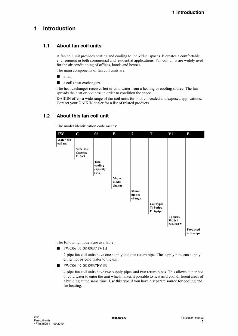
The model identification code means:
The following models are available:
■ FWC06-07-08-09B7TV1B
2-pipe fan coil units have one supply and one return pipe. The supply pipe can supply either hot or cold water to the unit.
■ FWC06-07-08-09B7FV1B
4-pipe fan coil units have two supply pipes and two return pipes. This allows either hot or cold water to enter the unit which makes it possible to heat and cool different areas of a building at the same time. Use this type if you have a separate source for cooling and for heating.
About this document
FW C 06 B 7 T V1 B
Water fan coil unit
Subclass:CassetteC: 3x3
Total cooling capacity (kW)
Major modelchange
Minor modelchange
Coil type:T: 2-pipeF: 4-pipe
1 phase / 50 Hz / 220-240 V
Produced in Europe
Installation manual
2FWC
Fan coil units4PW64525-1 – 09.2010
1 Introduction
1.3 About this document
This document is an installation manual. It is intended for the installer of this product. It describes the procedures for installing, commissioning and maintaining the unit, and it will provide help if problems occur. Carefully read the relevant parts of the manual.
How to get the manual?
■ A printed version of the manual is delivered with the unit.
■ Contact your local DAIKIN dealer for an electronic version of the manual.
For detailed instructions about how to install and operate the associated products and/or optional equipment, refer to the relevant catalogues, technical literature or product manuals for those products.
The original documentation is written in English. All other languages are translations of the original documentation.About this document
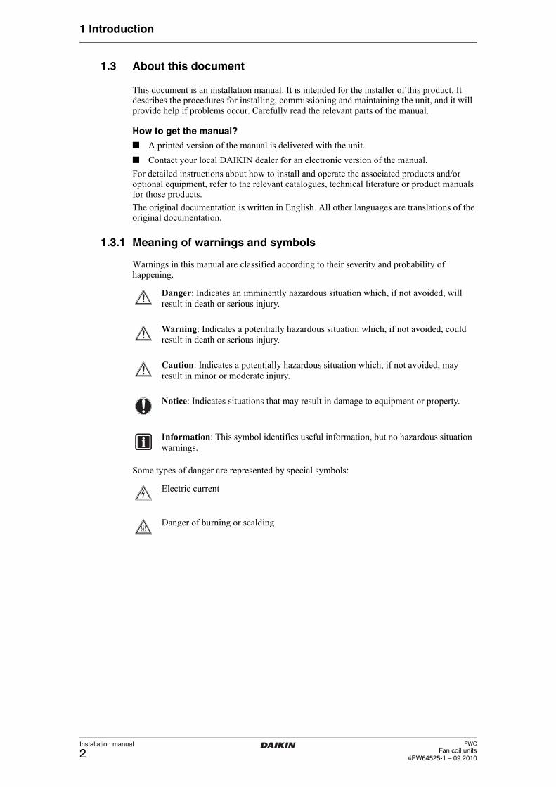
1.3.1 Meaning of warnings and symbols
Warnings in this manual are classified according to their severity and probability of happening.
Some types of danger are represented by special symbols:
Danger: Indicates an imminently hazardous situation which, if not avoided, will result in death or serious injury.
Warning: Indicates a potentially hazardous situation which, if not avoided, could result in death or serious injury.
Caution: Indicates a potentially hazardous situation which, if not avoided, may result in minor or moderate injury.
Notice: Indicates situations that may result in damage to equipment or property.
Information: This symbol identifies useful information, but no hazardous situation warnings.
Electric current
Danger of burning or scalding
FWCFan coil units4PW64525-1 – 09.2010
Installation manual
3
2 Precautions for installation
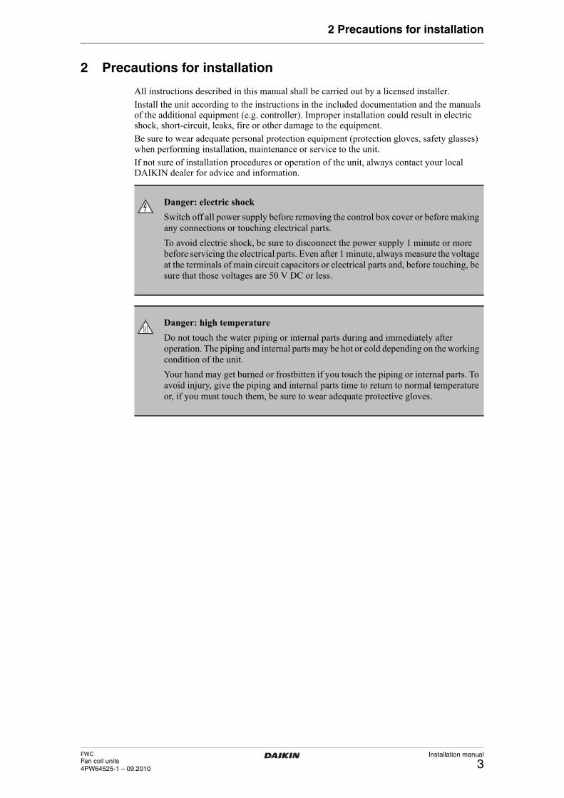
2 Precautions for installation
All instructions described in this manual shall be carried out by a licensed installer.
Install the unit according to the instructions in the included documentation and the manuals of the additional equipment (e.g. controller). Improper installation could result in electric shock, short-circuit, leaks, fire or other damage to the equipment.
Be sure to wear adequate personal protection equipment (protection gloves, safety glasses) when performing installation, maintenance or service to the unit.
If not sure of installation procedures or operation of the unit, always contact your local DAIKIN dealer for advice and information.
Danger: electric shock
Switch off all power supply before removing the control box cover or before making any connections or touching electrical parts.
To avoid electric shock, be sure to disconnect the power supply 1 minute or more before servicing the electrical parts. Even after 1 minute, always measure the voltage at the terminals of main circuit capacitors or electrical parts and, before touching, be sure that those voltages are 50 V DC or less.
Danger: high temperature
Do not touch the water piping or internal parts during and immediately after operation. The piping and internal parts may be hot or cold depending on the working condition of the unit.
Your hand may get burned or frostbitten if you touch the piping or internal parts. To avoid injury, give the piping and internal parts time to return to normal temperature or, if you must touch them, be sure to wear adequate protective gloves.
Installation manual
4FWC
Fan coil units4PW64525-1 – 09.2010
3 Prepare the installation of the fan coil unit
3 Prepare the installation of the fan coil unitCheck that you have all optional equipment
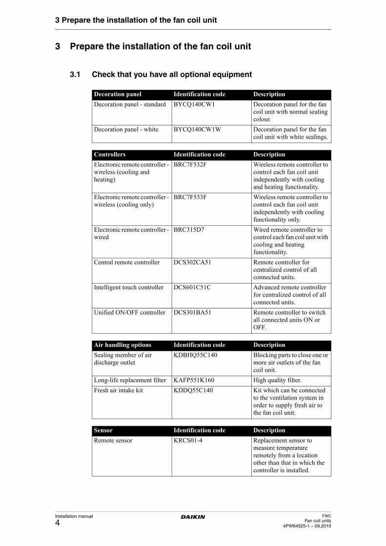
3.1 Check that you have all optional equipment
Decoration panel Identification code Description
Decoration panel - standard BYCQ140CW1 Decoration panel for the fan coil unit with normal sealing colour.
Decoration panel - white BYCQ140CW1W Decoration panel for the fan coil unit with white sealings.
Controllers Identification code Description
Electronic remote controller - wireless (cooling and heating)
BRC7F532F Wireless remote controller to control each fan coil unit independently with cooling and heating functionality.
Electronic remote controller - wireless (cooling only)
BRC7F533F Wireless remote controller to control each fan coil unit independently with cooling functionality only.
Electronic remote controller - wired
BRC315D7 Wired remote controller to control each fan coil unit with cooling and heating functionality.
Central remote controller DCS302CA51 Remote controller for centralized control of all connected units.
Intelligent touch controller DCS601C51C Advanced remote controller for centralized control of all connected units.
Unified ON/OFF controller DCS301BA51 Remote controller to switch all connected units ON or OFF.
Air handling options Identification code Description
Sealing member of air discharge outlet
KDBHQ55C140 Blocking parts to close one or more air outlets of the fan coil unit.
Long-life replacement filter KAFP551K160 High quality filter.
Fresh air intake kit KDDQ55C140 Kit which can be connected to the ventilation system in order to supply fresh air to the fan coil unit.
Sensor Identification code Description
Remote sensor KRCS01-4 Replacement sensor to measure temperature remotely from a location other than that in which the controller is installed.
FWCFan coil units4PW64525-1 – 09.2010
Installation manual
5
3 Prepare the installation of the fan coil unit
Verify the appropriate installation location
3.2 Verify the appropriate installation location
When selecting the installation location, take into account the instructions as mentioned in the following paragraphs of this chapter.
Select an installation location where the following conditions are fulfilled:
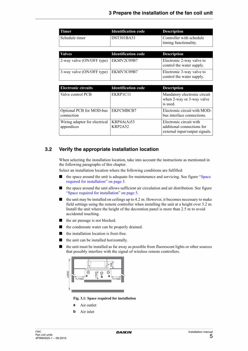
■ the space around the unit is adequate for maintenance and servicing. See figure “Space required for installation” on page 5.
■ the space around the unit allows sufficient air circulation and air distribution. See figure “Space required for installation” on page 5.
■ the unit may be installed on ceilings up to 4.2 m. However, it becomes necessary to make field settings using the remote controller when installing the unit at a height over 3.2 m.Install the unit where the height of the decoration panel is more than 2.5 m to avoid accidental touching.
■ the air passage is not blocked.
■ the condensate water can be properly drained.
■ the installation location is frost-free.
■ the unit can be installed horizontally.
■ the unit must be installed as far away as possible from fluorescent lights or other sources that possibly interfere with the signal of wireless remote controllers.
Fig. 3.1: Space required for installation
Timer Identification code Description
Schedule timer DST301BA51 Controller with schedule timing functionality.
Valves Identification code Description
2-way valve (ON/OFF type) EKMV2C09B7 Electronic 2-way valve to control the water supply.
3-way valve (ON/OFF type) EKMV3C09B7 Electronic 3-way valve to control the water supply.
Electronic circuits Identification code Description
Valve control PCB EKRP1C11 Mandatory electronic circuit when 2-way or 3-way valve is used.
Optional PCB for MOD-bus connection
EKFCMBCB7 Electronic circuit with MOD-bus interface connections.
Wiring adaptor for electrical appendices
KRP4A(A)53 KRP2A52
Electronic circuit with additional connections for external input/output signals.
a ab≥250
0
≥150
0
298
*≥1500 *≥1500
a Air outlet
b Air inlet
Installation manual
6FWC
Fan coil units4PW64525-1 – 09.2010
3 Prepare the installation of the fan coil unit
Prepare the installation space
3.3 Prepare the installation space
■ When preparing the installation space, use the paper pattern for installation which is delivered with the unit. More information on how to prepare the ceiling opening can be found in chapter “Prepare the ceiling opening” on page 11.
■ When the conditions in the built-in space are exceeding 30°C and exceeding a relative humidity of 80%, or when fresh air is inducted into the ceiling, an additional insulation is required on the outside of the unit (minimum 10 mm thickness polyethylene foam).
Prepare the water piping work
3.4 Prepare the water piping work
The unit is equipped with a water inlet and water outlet for connection to a water circuit. The water circuit must be provided by an installer and must comply with the applicable legislation.
Before performing the water piping work, check the following points:
■ the maximum water pressure is 10 bar,
■ the minimum water temperature is 5°C,
■ the maximum water temperature is 70°C,
■ be sure to install components in the field piping that can withstand the water pressure and temperature,
■ provide adequate safeguards in the water circuit to be sure that the water pressure will never exceed the maximum allowable working pressure,
■ provide a proper drain for the pressure relief valve (if installed) to avoid any water coming into contact with electrical parts,
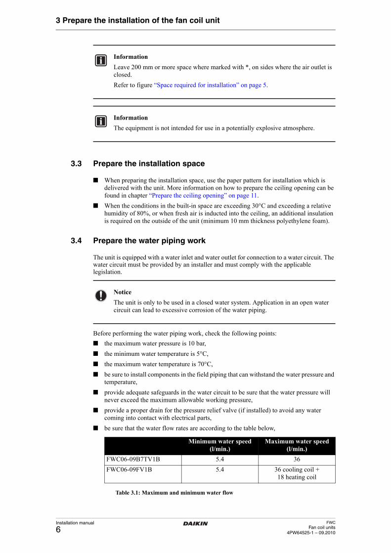
■ be sure that the water flow rates are according to the table below,
Table 3.1: Maximum and minimum water flow
Information
Leave 200 mm or more space where marked with *, on sides where the air outlet is closed.
Refer to figure “Space required for installation” on page 5.
Information
The equipment is not intended for use in a potentially explosive atmosphere.
Notice
The unit is only to be used in a closed water system. Application in an open water circuit can lead to excessive corrosion of the water piping.
Minimum water speed (l/min.)
Maximum water speed (l/min.)
FWC06-09B7TV1B 5.4 36
FWC06-09FV1B 5.4 36 cooling coil + 18 heating coil
FWCFan coil units4PW64525-1 – 09.2010
Installation manual
7
3 Prepare the installation of the fan coil unit
■ provide shut-off valves at the unit so that normal servicing can be accomplished without draining the system,
■ provide drain taps at all low points of the system to permit complete drainage of the circuit during maintenance or service to the unit,
■ provide air purge valves at all high points of the system. The valves shall be located at points which are easily accessible for servicing. A manual air purge valve is mounted onto the unit,
■ always use materials which are compatible with the water and 40% volume glycol,
■ select piping diameter in relation to required water flow and available ESP (External Static Pressure) of the pump.
Prepare the electrical wiring work
3.5 Prepare the electrical wiring work
The unit must be connected to the power supply. All field wiring and components must be installed by an installer and must comply with the applicable legislation.
Before connecting the electrical wiring, check the following points:
■ use copper wires only,
■ all field wiring must be carried out in accordance with the wiring diagram delivered with the unit,
■ never squeeze bundled cables and be sure that cables do not come in contact with the piping and sharp edges. Be sure no external pressure is applied to the terminal connections,
■ be sure to establish an earth. Do not earth the unit to a utility pipe, surge absorber, or telephone earth. Incomplete earth may cause electrical shock,
■ be sure to install an earth leakage detector in accordance with the applicable legislation. Failure to do so may cause electric shock or fire. The earth leakage detector is a field supplied part,
■ be sure to install the required fuses or circuit breakers. The fuse or circuit breakers are field supplied parts.
Warning
A main switch or other means for disconnection, having a contact separation in all poles, must be incorporated in the fixed wiring in accordance with the applicable legislation.
Information
The equipment described in this manual may cause electronic noise generated from radio-frequency energy. The equipment complies to specifications that are designed to provide reasonable protection against such interference. However, there is no guarantee that interference will not occur in a particular installation.
It is therefore recommended to install the equipment and electric wires keeping proper distances away from stereo equipment, personal computers, etc.
In extreme circumstances a distance of 3 m or more is required.
Installation manual
8FWC
Fan coil units4PW64525-1 – 09.2010
3 Prepare the installation of the fan coil unit
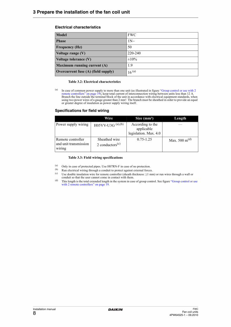
Electrical characteristics
Table 3.2: Electrical characteristics
(a) In case of common power supply to more than one unit (as illustrated in figure “Group control or use with 2 remote controllers” on page 19), keep total current of interconnection wiring between units less than 12 A. Branch the line outside the terminal block of the unit in accordance with electrical equipment standards, when using two power wires of a gauge greater than 2 mm². The branch must be sheathed in order to provide an equal or greater degree of insulation as power supply wiring itself.
Specifications for field wiring
Table 3.3: Field wiring specifications
(a) Only in case of protected pipes. Use H07RN-F in case of no protection.(b) Run electrical wiring through a conduit to protect against external forces.(c) Use double insulation wire for remote controller (sheath thickness: ≥1 mm) or run wires through a wall or
conduit so that the user cannot come in contact with them.(d) This length is the total extended length in the system in case of group control. See figure “Group control or use
with 2 remote controllers” on page 19.Prepare the installation of optional equipment
Model FWC
Phase 1N~
Frequency (Hz) 50
Voltage range (V) 220-240
Voltage tolerance (V) ±10%
Maximum running current (A) 1.9
Overcurrent fuse (A) (field supply) 16 (a)
Wire Size (mm²) Length
Power supply wiring H05VV-U3G (a),(b) According to the applicable
legislation. Max. 4.0
—
Remote controller and unit transmission wiring
Sheathed wire
2 conductors(c)0.75-1.25 Max. 500 m(d)
FWCFan coil units4PW64525-1 – 09.2010
Installation manual
9
3 Prepare the installation of the fan coil unit
3.6 Prepare the installation of optional equipment
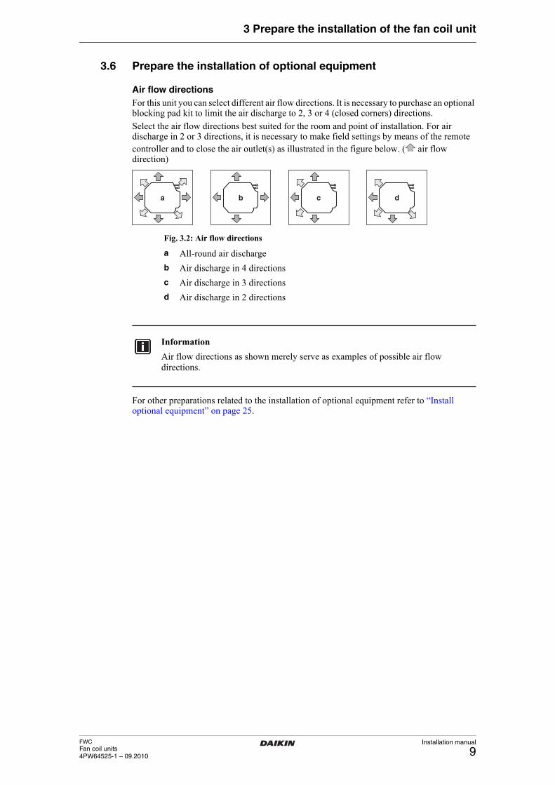
Air flow directionsFor this unit you can select different air flow directions. It is necessary to purchase an optional blocking pad kit to limit the air discharge to 2, 3 or 4 (closed corners) directions.
Select the air flow directions best suited for the room and point of installation. For air discharge in 2 or 3 directions, it is necessary to make field settings by means of the remote controller and to close the air outlet(s) as illustrated in the figure below. ( air flow direction)
Fig. 3.2: Air flow directions
For other preparations related to the installation of optional equipment refer to “Install optional equipment” on page 25.
a b c d
a All-round air discharge
b Air discharge in 4 directions
c Air discharge in 3 directions
d Air discharge in 2 directions
Information
Air flow directions as shown merely serve as examples of possible air flow directions.
Installation manual
10FWC
Fan coil units4PW64525-1 – 09.2010
4 Install the fan coil unit
4 Install the fan coil unitUnpack the unit
4.1 Unpack the unit
When receiving the unit, please check its state. Verify if any damage occurred during transport. If the unit and/or packing are damaged at delivery, report this immediately to the carrier’s claims agent.
Identify model and version of the unit from the indications stated on the carton packing.
Leave the unit inside its packing until you reach the installation site. Where unpacking is unavoidable, use a sling of soft material or protective plates together with a rope when lifting, this to avoid damage or scratches to the unit.
When unpacking the unit or when moving the unit after unpacking, be sure to lift the unit by holding on to the hanger bracket without exerting any pressure on other parts. Check if all accessories are included
4.2 Check if all accessories are included
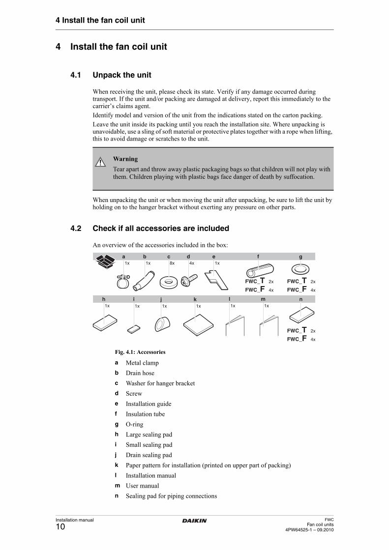
An overview of the accessories included in the box:
Fig. 4.1: Accessories
Prepare the ceiling opening
Warning
Tear apart and throw away plastic packaging bags so that children will not play with them. Children playing with plastic bags face danger of death by suffocation.
1x
a b c ed1x 1x 8x 4x 1x
f g
1xh n
1x 1x
i j1x
k l1x
m
FWC_T 2x
FWC_F 4x
FWC_T 2x
FWC_F 4x
FWC_T 2x
FWC_F 4x
a Metal clamp
b Drain hose
c Washer for hanger bracket
d Screw
e Installation guide
f Insulation tube
g O-ring
h Large sealing pad
i Small sealing pad
j Drain sealing pad
k Paper pattern for installation (printed on upper part of packing)
l Installation manual
m User manual
n Sealing pad for piping connections
FWCFan coil units4PW64525-1 – 09.2010
Installation manual
11
4 Install the fan coil unit
4.3 Prepare the ceiling opening
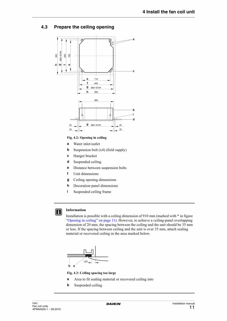
Fig. 4.2: Opening in ceiling
Fig. 4.3: Ceiling spacing too large
710
840
860~910*
860
860~910*
950
20
35
20
35
780
840
860~910 *
950
a
c
efg
g
h
h g f e
b
di
a Water inlet/outlet
b Suspension bolt (x4) (field supply)
c Hanger bracket
d Suspended ceiling
e Distance between suspension bolts
f Unit dimensions
g Ceiling opening dimensions
h Decoration panel dimensions
i Suspended ceiling frame
Information
Installation is possible with a ceiling dimension of 910 mm (marked with * in figure “Opening in ceiling” on page 11). However, to achieve a ceiling-panel overlapping dimension of 20 mm, the spacing between the ceiling and the unit should be 35 mm or less. If the spacing between ceiling and the unit is over 35 mm, attach sealing material or recovered ceiling in the area marked below.
≤35
b a
a Area to fit sealing material or recovered ceiling into
b Suspended ceiling
Installation manual
12FWC
Fan coil units4PW64525-1 – 09.2010
4 Install the fan coil unit
1 Make the ceiling opening needed for installation where applicable. (For existing ceilings.)
■ Refer to the paper pattern for installation (delivered with the unit) for the ceiling opening dimensions.
■ Create the ceiling opening required for installation.
■ After making an opening in the ceiling, it may be necessary to reinforce the suspended ceiling frame to keep the ceiling level and to prevent it from vibrating. Consult the builder for details.
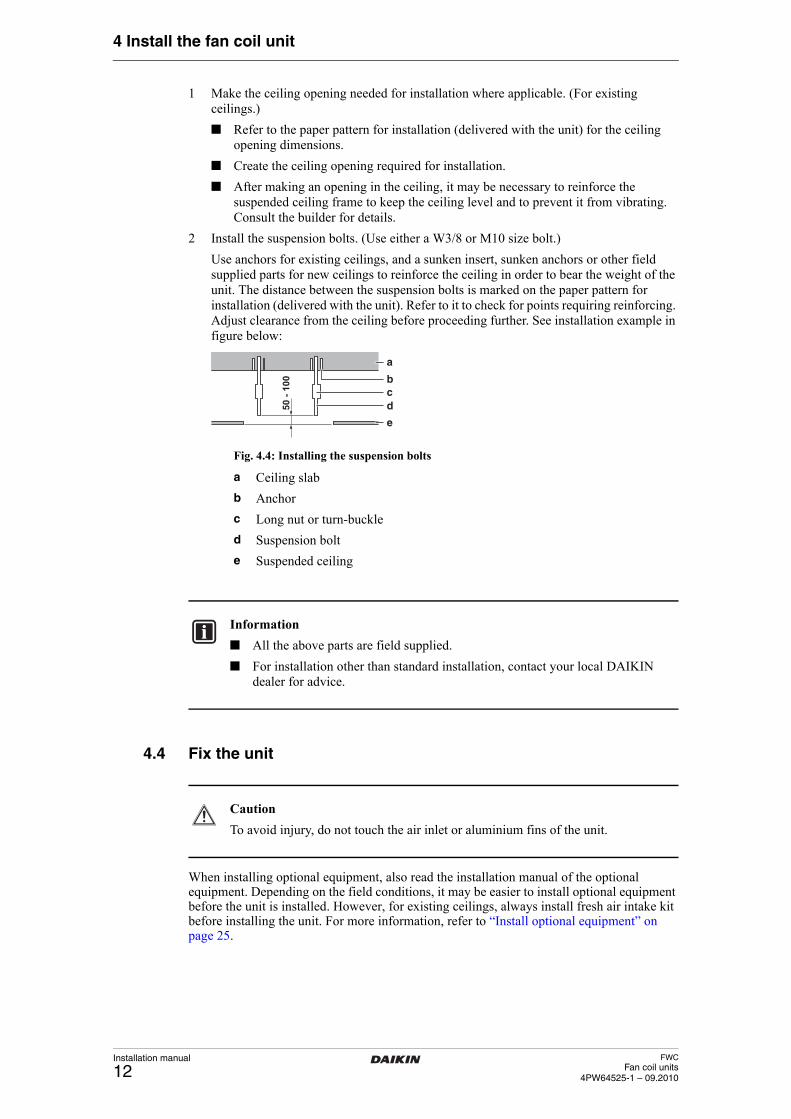
2 Install the suspension bolts. (Use either a W3/8 or M10 size bolt.)
Use anchors for existing ceilings, and a sunken insert, sunken anchors or other field supplied parts for new ceilings to reinforce the ceiling in order to bear the weight of the unit. The distance between the suspension bolts is marked on the paper pattern for installation (delivered with the unit). Refer to it to check for points requiring reinforcing. Adjust clearance from the ceiling before proceeding further. See installation example in figure below:
Fig. 4.4: Installing the suspension bolts
Fix the unit
4.4 Fix the unit
When installing optional equipment, also read the installation manual of the optional equipment. Depending on the field conditions, it may be easier to install optional equipment before the unit is installed. However, for existing ceilings, always install fresh air intake kit before installing the unit. For more information, refer to “Install optional equipment” on page 25.
cb
d
e
a
50 -
100
a Ceiling slab
b Anchor
c Long nut or turn-buckle
d Suspension bolt
e Suspended ceiling
Information
■ All the above parts are field supplied.
■ For installation other than standard installation, contact your local DAIKIN dealer for advice.
Caution
To avoid injury, do not touch the air inlet or aluminium fins of the unit.
FWCFan coil units4PW64525-1 – 09.2010
Installation manual
13
4 Install the fan coil unit
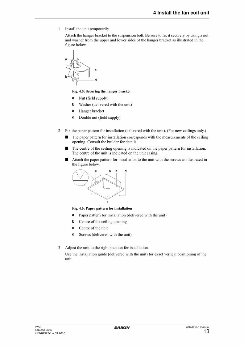
1 Install the unit temporarily.
Attach the hanger bracket to the suspension bolt. Be sure to fix it securely by using a nut and washer from the upper and lower sides of the hanger bracket as illustrated in the figure below.
Fig. 4.5: Securing the hanger bracket
2 Fix the paper pattern for installation (delivered with the unit). (For new ceilings only.)
■ The paper pattern for installation corresponds with the measurements of the ceiling opening. Consult the builder for details.
■ The centre of the ceiling opening is indicated on the paper pattern for installation. The centre of the unit is indicated on the unit casing.
■ Attach the paper pattern for installation to the unit with the screws as illustrated in the figure below.
Fig. 4.6: Paper pattern for installation
3 Adjust the unit to the right position for installation.
Use the installation guide (delivered with the unit) for exact vertical positioning of the unit.
b
a
c
d
a Nut (field supply)
b Washer (delivered with the unit)
c Hanger bracket
d Double nut (field supply)
c ab d
a Paper pattern for installation (delivered with the unit)
b Centre of the ceiling opening
c Centre of the unit
d Screws (delivered with the unit)
Installation manual
14FWC
Fan coil units4PW64525-1 – 09.2010
4 Install the fan coil unit
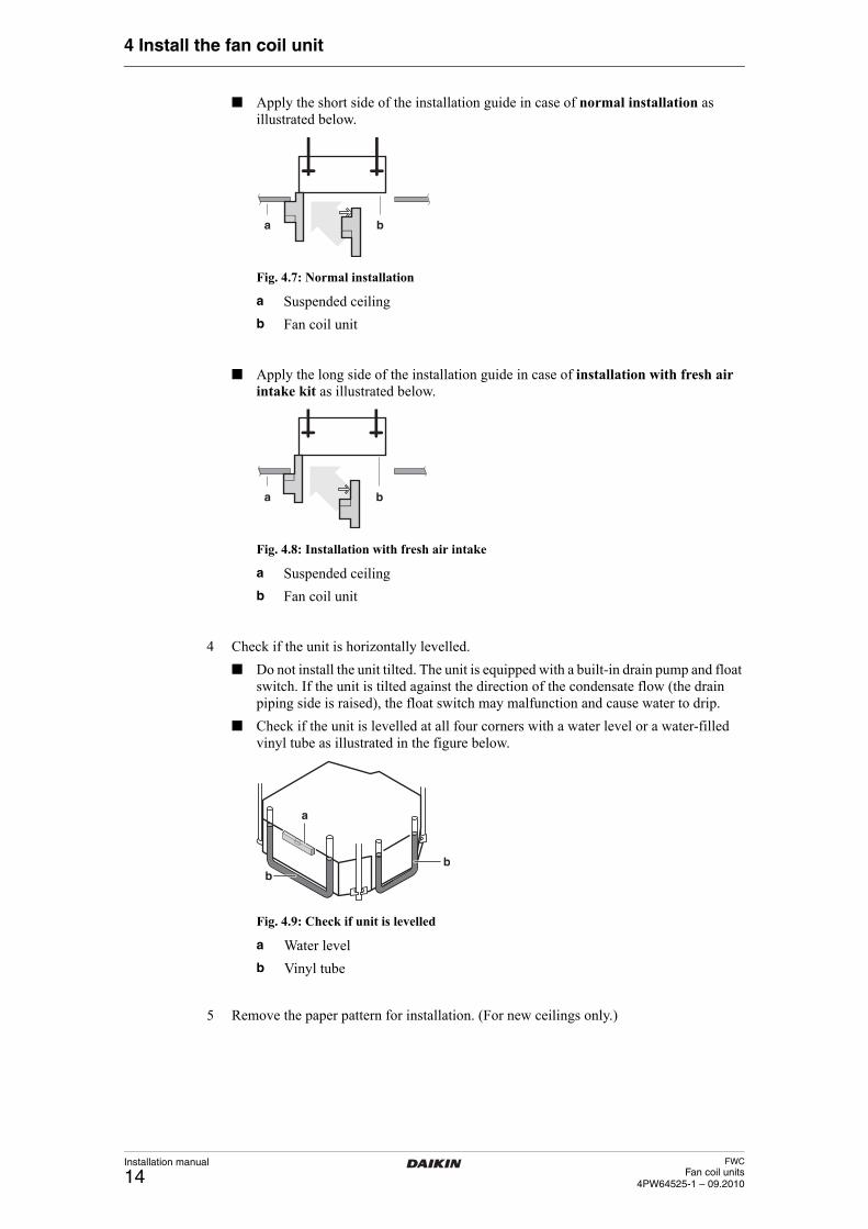
■ Apply the short side of the installation guide in case of normal installation as illustrated below.
Fig. 4.7: Normal installation
■ Apply the long side of the installation guide in case of installation with fresh air intake kit as illustrated below.
Fig. 4.8: Installation with fresh air intake
4 Check if the unit is horizontally levelled.
■ Do not install the unit tilted. The unit is equipped with a built-in drain pump and float switch. If the unit is tilted against the direction of the condensate flow (the drain piping side is raised), the float switch may malfunction and cause water to drip.
■ Check if the unit is levelled at all four corners with a water level or a water-filled vinyl tube as illustrated in the figure below.
Fig. 4.9: Check if unit is levelled
5 Remove the paper pattern for installation. (For new ceilings only.)Perform the water piping work
a b
a Suspended ceiling
b Fan coil unit
a b
a Suspended ceiling
b Fan coil unit
bb
a
a Water level
b Vinyl tube
FWCFan coil units4PW64525-1 – 09.2010
Installation manual
15
4 Install the fan coil unit
4.5 Perform the water piping work
Perform the water piping work
4.5.1 Connect the water pipes
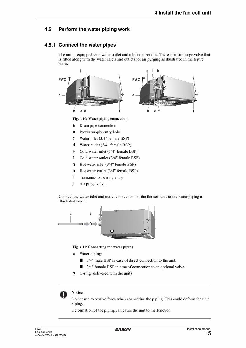
The unit is equipped with water outlet and inlet connections. There is an air purge valve that is fitted along with the water inlets and outlets for air purging as illustrated in the figure below.
Fig. 4.10: Water piping connection
Connect the water inlet and outlet connections of the fan coil unit to the water piping as illustrated below.
Fig. 4.11: Connecting the water piping
a
i
j j
ib c d
a
b e f
g h
FWC_T FWC_FFWC_T FWC_F
a Drain pipe connection
b Power supply entry hole
c Water inlet (3/4" female BSP)
d Water outlet (3/4" female BSP)
e Cold water inlet (3/4" female BSP)
f Cold water outlet (3/4" female BSP)
g Hot water inlet (3/4" female BSP)
h Hot water outlet (3/4" female BSP)
i Transmission wiring entry
j Air purge valve
ba
a Water piping:
■ 3/4" male BSP in case of direct connection to the unit,
■ 3/4" female BSP in case of connection to an optional valve.
b O-ring (delivered with the unit)
Notice
Do not use excessive force when connecting the piping. This could deform the unit piping.
Deformation of the piping can cause the unit to malfunction.
Installation manual
16FWC
Fan coil units4PW64525-1 – 09.2010
4 Install the fan coil unit
In case the optional valve is used, refer to the installation manual of the valve kit to install the field piping.Perform the water piping work
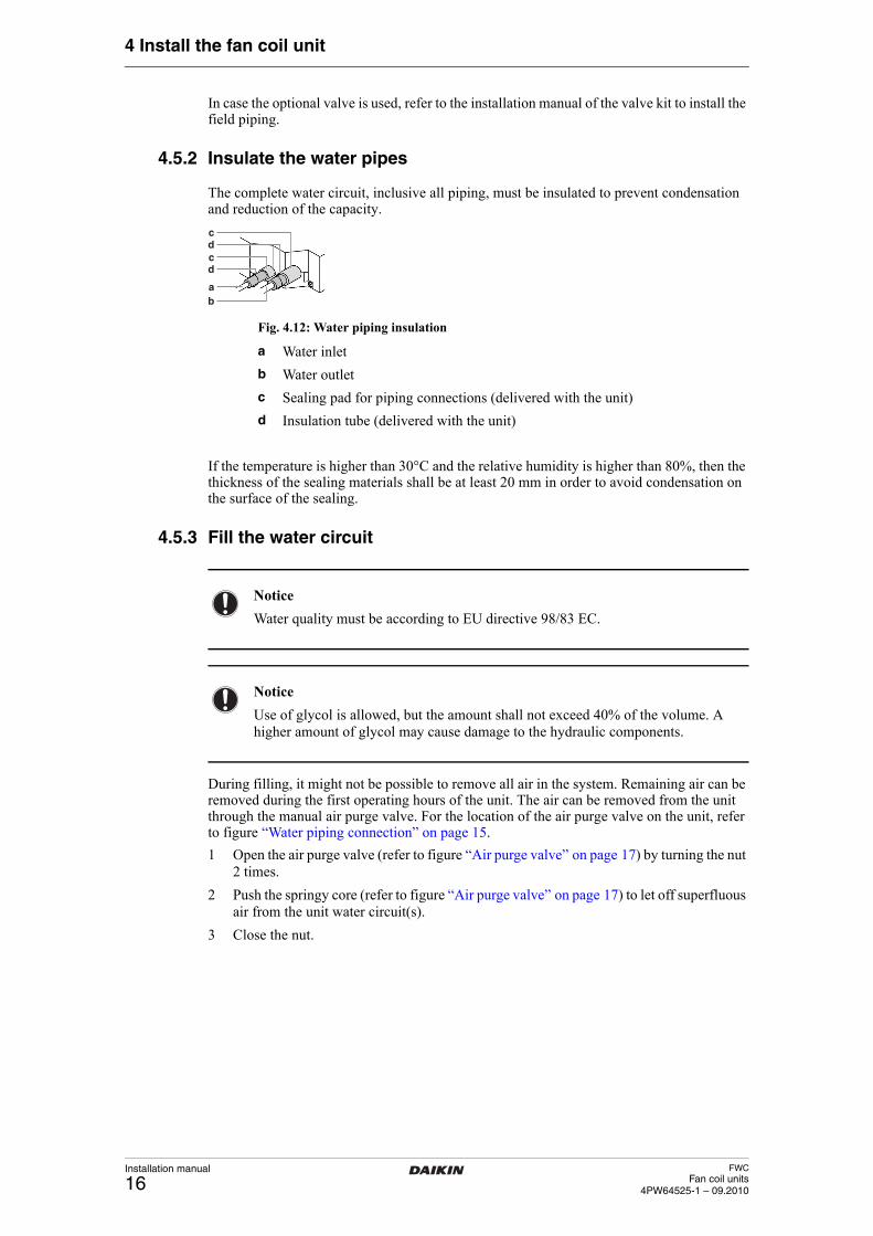
4.5.2 Insulate the water pipes
The complete water circuit, inclusive all piping, must be insulated to prevent condensation and reduction of the capacity.
Fig. 4.12: Water piping insulation
If the temperature is higher than 30°C and the relative humidity is higher than 80%, then the thickness of the sealing materials shall be at least 20 mm in order to avoid condensation on the surface of the sealing.Perform the water piping work
4.5.3 Fill the water circuit
During filling, it might not be possible to remove all air in the system. Remaining air can be removed during the first operating hours of the unit. The air can be removed from the unit through the manual air purge valve. For the location of the air purge valve on the unit, refer to figure “Water piping connection” on page 15.
1 Open the air purge valve (refer to figure “Air purge valve” on page 17) by turning the nut 2 times.
2 Push the springy core (refer to figure “Air purge valve” on page 17) to let off superfluous air from the unit water circuit(s).
3 Close the nut.
ab
dc
cd
a Water inlet
b Water outlet
c Sealing pad for piping connections (delivered with the unit)
d Insulation tube (delivered with the unit)
Notice
Water quality must be according to EU directive 98/83 EC.
Notice
Use of glycol is allowed, but the amount shall not exceed 40% of the volume. A higher amount of glycol may cause damage to the hydraulic components.
FWCFan coil units4PW64525-1 – 09.2010
Installation manual
17
4 Install the fan coil unit
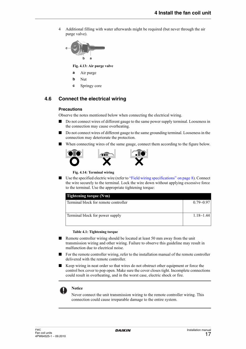
4 Additional filling with water afterwards might be required (but never through the air purge valve).
Fig. 4.13: Air purge valve
Connect the electrical wiring
4.6 Connect the electrical wiring
PrecautionsObserve the notes mentioned below when connecting the electrical wiring.
■ Do not connect wires of different gauge to the same power supply terminal. Looseness in the connection may cause overheating.
■ Do not connect wires of different gauge to the same grounding terminal. Looseness in the connection may deteriorate the protection.
■ When connecting wires of the same gauge, connect them according to the figure below.
Fig. 4.14: Terminal wiring
■ Use the specified electric wire (refer to “Field wiring specifications” on page 8). Connect the wire securely to the terminal. Lock the wire down without applying excessive force to the terminal. Use the appropriate tightening torque:
Table 4.1: Tightening torque
■ Remote controller wiring should be located at least 50 mm away from the unit transmission wiring and other wiring. Failure to observe this guideline may result in malfunction due to electrical noise.
■ For the remote controller wiring, refer to the installation manual of the remote controller delivered with the remote controller.
■ Keep wiring in neat order so that wires do not obstruct other equipment or force the control box cover to pop open. Make sure the cover closes tight. Incomplete connections could result in overheating, and in the worst case, electric shock or fire.
ab
c
a Air purge
b Nut
c Springy core
Tightening torque (N·m)
Terminal block for remote controller 0.79~0.97
Terminal block for power supply 1.18~1.44
Notice
Never connect the unit transmission wiring to the remote controller wiring. This connection could cause irreparable damage to the entire system.
Installation manual
18FWC
Fan coil units4PW64525-1 – 09.2010
4 Install the fan coil unit
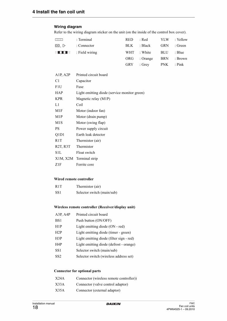
Wiring diagramRefer to the wiring diagram sticker on the unit (on the inside of the control box cover).
Wired remote controller
Wireless remote controller (Receiver/display unit)
Connector for optional parts
: Terminal RED : Red YLW : Yellow
: Connector BLK : Black GRN : Green
: Field wiring WHT : White BLU : Blue
ORG : Orange BRN : Brown
GRY : Grey PNK : Pink
A1P, A2P Printed circuit board
C1 Capacitor
F1U Fuse
HAP Light emitting diode (service monitor green)
KPR Magnetic relay (M1P)
L1 Coil
M1F Motor (indoor fan)
M1P Motor (drain pump)
M1S Motor (swing flap)
PS Power supply circuit
Q1D1 Earth leak detector
R1T Thermistor (air)
R2T, R3T Thermistor
S1L Float switch
X1M, X2M Terminal strip
Z1F Ferrite core
R1T Thermistor (air)
SS1 Selector switch (main/sub)
A3P, A4P Printed circuit board
BS1 Push button (ON/OFF)
H1P Light emitting diode (ON - red)
H2P Light emitting diode (timer - green)
H3P Light emitting diode (filter sign - red)
H4P Light emitting diode (defrost - orange)
SS1 Selector switch (main/sub)
SS2 Selector switch (wireless address set)
X24A Connector (wireless remote controller))
X33A Connector (valve control adaptor)
X35A Connector (external adaptor)
FWCFan coil units4PW64525-1 – 09.2010
Installation manual
19
4 Install the fan coil unit
Notes
1 If a central remote controller is used, connect it to the unit in accordance with the controller installation manual.
2 X24A, X33A and X35A are connected when optional accessories are used.
3 Confirm the method of setting the selector switch (SS1, SS2) using the installation manual, engineering data, etc.
4 Availability of R2T and/or R3T is depending on model type.
System examples
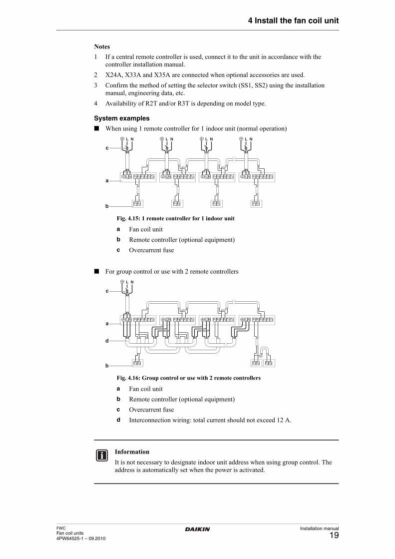
■ When using 1 remote controller for 1 indoor unit (normal operation)
Fig. 4.15: 1 remote controller for 1 indoor unit
■ For group control or use with 2 remote controllers
Fig. 4.16: Group control or use with 2 remote controllers
P1L
NL
aN P2 F1 F2 T1 T2 P1L
NL
N P2 F1 F2 T1 T2P1L
NL
N P2
P1 P2 P1 P2 P1 P2 P1 P2
F1 F2 T1 T2 P1L
NL
N P2 F1 F2 T1 T2
c
b
a Fan coil unit
b Remote controller (optional equipment)
c Overcurrent fuse
P1La
N P2 F1 F2 T1 T2 P1L N P2 F1 F2 T1 T2P1L
NL
N P2
P1 P2 P1 P2 P1 P2
F1 F2 T1 T2 P1L N P2 F1 F2 T1 T2
b
d
c
a Fan coil unit
b Remote controller (optional equipment)
c Overcurrent fuse
d Interconnection wiring: total current should not exceed 12 A.
Information
It is not necessary to designate indoor unit address when using group control. The address is automatically set when the power is activated.
Installation manual
20FWC
Fan coil units4PW64525-1 – 09.2010
4 Install the fan coil unit
■ For forced OFF and ON/OFF operation, connect input wires from the outside to terminals T1 and T2 of the terminal board (remote controller to transmission wiring).
Table 4.2: Forced OFF and ON/OFF wiring specificationsConnect the electrical wiring
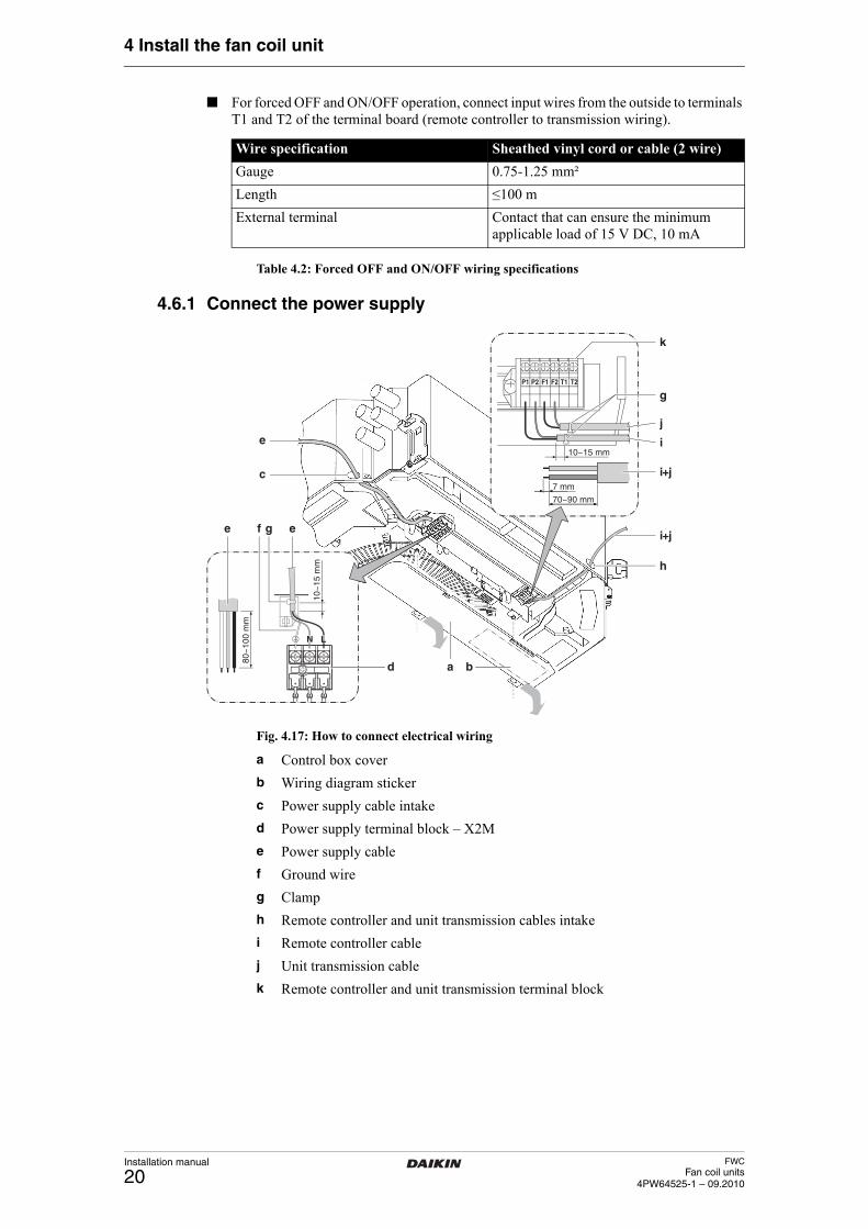
4.6.1 Connect the power supply
Fig. 4.17: How to connect electrical wiring
Wire specification Sheathed vinyl cord or cable (2 wire)
Gauge 0.75-1.25 mm²
Length ≤100 m
External terminal Contact that can ensure the minimum applicable load of 15 V DC, 10 mA
80~
100
mm
10~
15 m
m
a b
e
c
e egi+j
h
f
d
LN
70~90 mm
7 mm
10~15 mm
F1 F2P1 P2 T1 T2
k
i+j
j
i
g
a Control box cover
b Wiring diagram sticker
c Power supply cable intake
d Power supply terminal block – X2M
e Power supply cable
f Ground wire
g Clamp
h Remote controller and unit transmission cables intake
i Remote controller cable
j Unit transmission cable
k Remote controller and unit transmission terminal block
FWCFan coil units4PW64525-1 – 09.2010
Installation manual
21
4 Install the fan coil unit
1 Remove the control box cover (a) as illustrated in figure “How to connect electrical wiring” on page 20.
2 Pull the power supply cable (e) (or interconnection wiring in case of common power supply) inside through the power supply cable intake (c).
3 Strip the wires to the recommended length.
4 Connect the power supply wires to the power supply terminal block (d).
5 Connect the ground wire (f) to the grounding terminal.
6 Securely fix the wiring using a clamp (g).
7 Install an earth leakage detector and fuse in the power supply line (field supply). Select the earth leakage detector in accordance with the applicable legislation. To select the fuse, refer to “Electrical characteristics” on page 8.
Connect the electrical wiring
4.6.2 Connect the remote controller and unit transmission wiring
1 Remove the control box cover (a) as illustrated in figure “How to connect electrical wiring” on page 20.
2 Pull the cables (i, j) inside through the remote controller and unit transmission cables intake (h).
3 Strip the wires to the recommended length.
4 Connect the remote controller wires to (P1, P2) terminals of the terminal block (k).
5 Connect the unit transmission wires to (F1, F2) terminals.
6 Securely fix the wiring using a clamp (g).Connect the electrical wiring
4.6.3 Close the control box
1 After all wiring connections are executed, fill gaps in the casing cable intakes with the small sealing pad (delivered with the unit) to prevent small animals, water or dirt from entering the unit causing short circuits in the control box.
2 Fit the control box cover (a) back in place like illustrated in figure “How to connect electrical wiring” on page 20. When attaching the control box cover, make sure not to pinch any wires.
Perform the drain piping work
4.7 Perform the drain piping work
Perform the drain piping work
4.7.1 Install the drain piping in the building
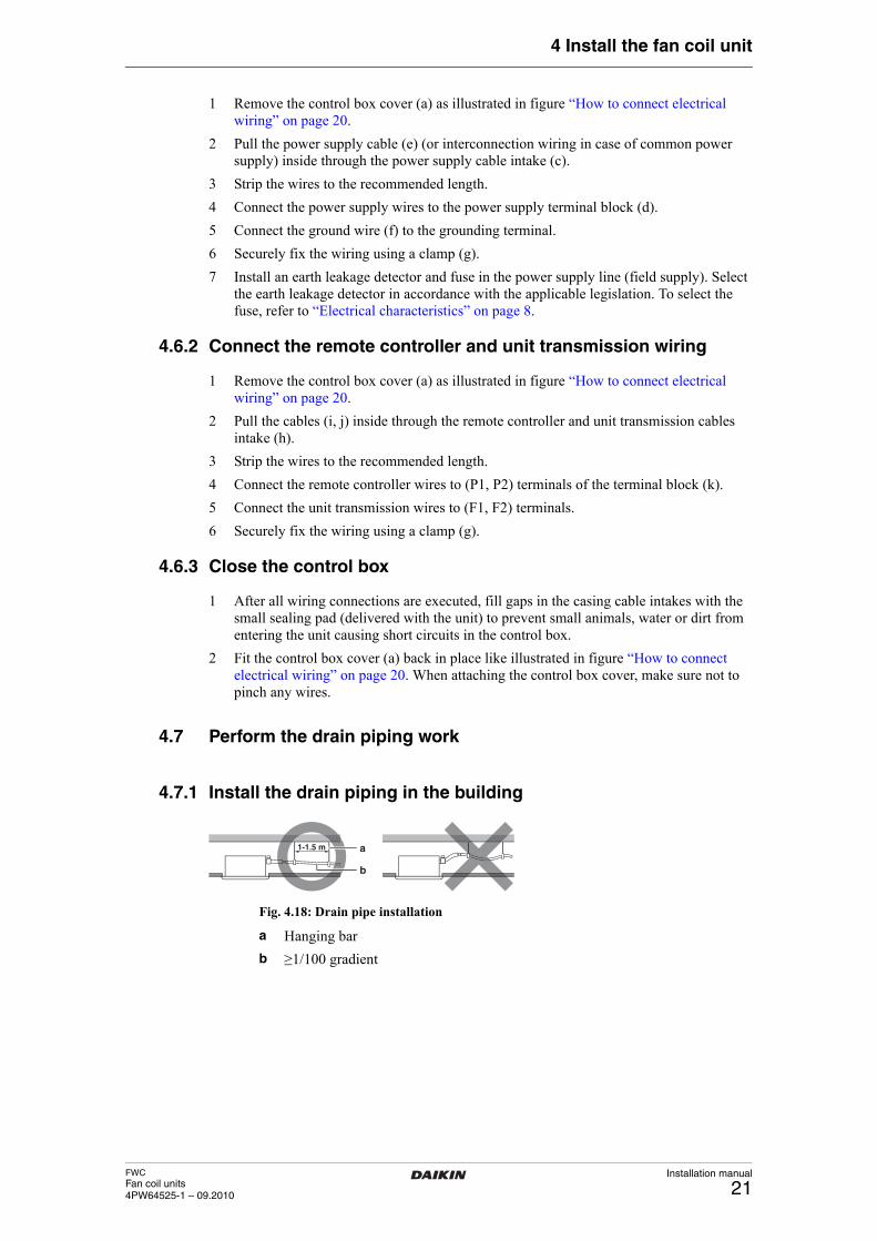
Fig. 4.18: Drain pipe installation
1-1.5 m a
b
a Hanging bar
b ≥1/100 gradient
Installation manual
22FWC
Fan coil units4PW64525-1 – 09.2010
4 Install the fan coil unit
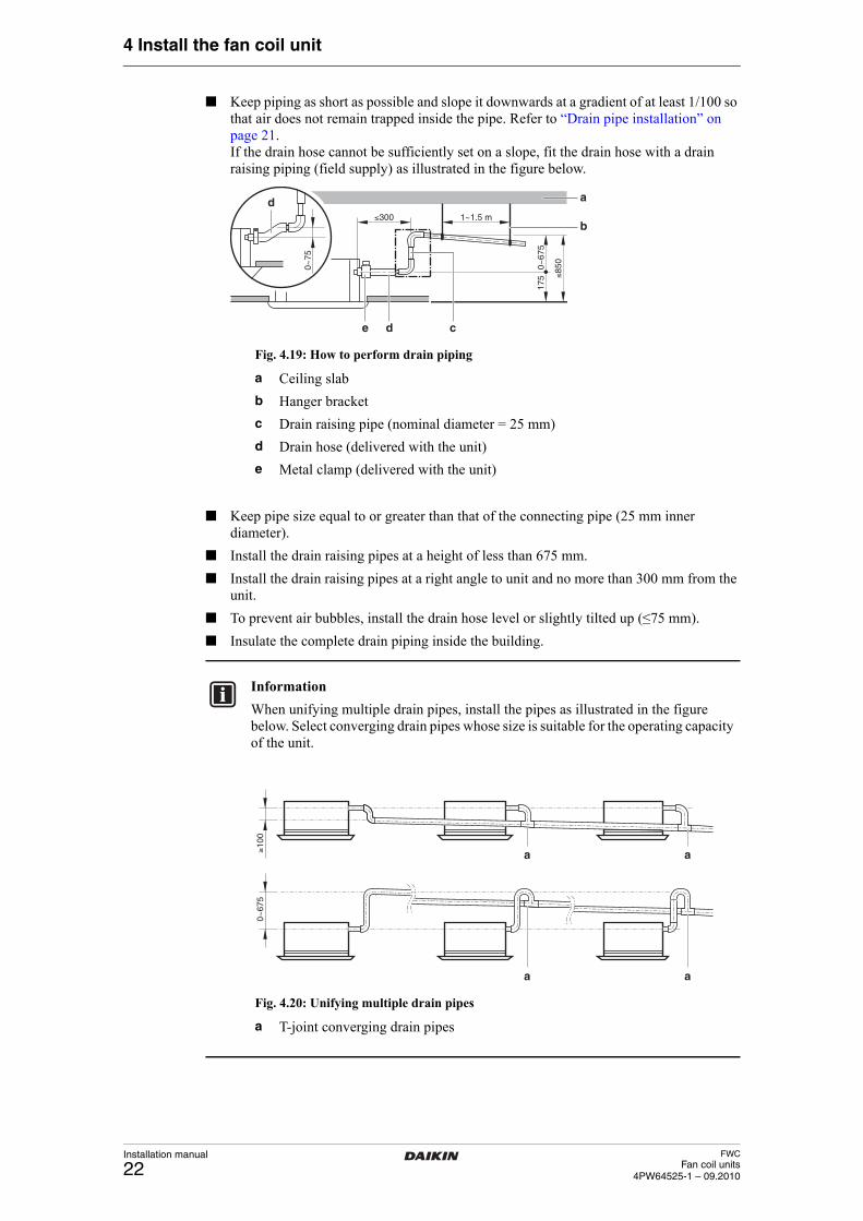
■ Keep piping as short as possible and slope it downwards at a gradient of at least 1/100 so that air does not remain trapped inside the pipe. Refer to “Drain pipe installation” on page 21.If the drain hose cannot be sufficiently set on a slope, fit the drain hose with a drain raising piping (field supply) as illustrated in the figure below.
Fig. 4.19: How to perform drain piping
■ Keep pipe size equal to or greater than that of the connecting pipe (25 mm inner diameter).
■ Install the drain raising pipes at a height of less than 675 mm.
■ Install the drain raising pipes at a right angle to unit and no more than 300 mm from the unit.
■ To prevent air bubbles, install the drain hose level or slightly tilted up (≤75 mm).
■ Insulate the complete drain piping inside the building.
Fig. 4.20: Unifying multiple drain pipes
Perform the drain piping work
≤300
0~67
517
5 ≤85
0
1~1.5 m
0~75
a
b
d
d
ce
a Ceiling slab
b Hanger bracket
c Drain raising pipe (nominal diameter = 25 mm)
d Drain hose (delivered with the unit)
e Metal clamp (delivered with the unit)
Information
When unifying multiple drain pipes, install the pipes as illustrated in the figure below. Select converging drain pipes whose size is suitable for the operating capacity of the unit.
≥10
0 0
~67
5
a a
a a
a T-joint converging drain pipes
FWCFan coil units4PW64525-1 – 09.2010
Installation manual
23
4 Install the fan coil unit
4.7.2 Connect the drain piping to the unit
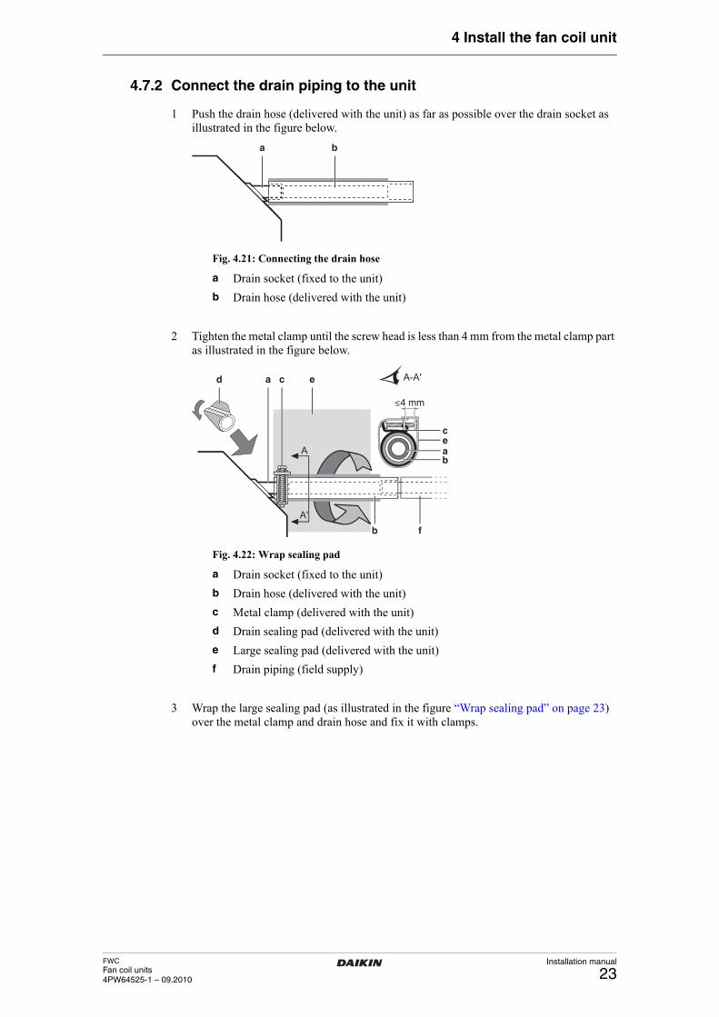
1 Push the drain hose (delivered with the unit) as far as possible over the drain socket as illustrated in the figure below.
Fig. 4.21: Connecting the drain hose
2 Tighten the metal clamp until the screw head is less than 4 mm from the metal clamp part as illustrated in the figure below.
Fig. 4.22: Wrap sealing pad
3 Wrap the large sealing pad (as illustrated in the figure “Wrap sealing pad” on page 23) over the metal clamp and drain hose and fix it with clamps.
Perform the drain piping work
ba
a Drain socket (fixed to the unit)
b Drain hose (delivered with the unit)
a
fb
d c e
≤4 mm
ce
bA
A'
A-A'
a
a Drain socket (fixed to the unit)
b Drain hose (delivered with the unit)
c Metal clamp (delivered with the unit)
d Drain sealing pad (delivered with the unit)
e Large sealing pad (delivered with the unit)
f Drain piping (field supply)
Installation manual
24FWC
Fan coil units4PW64525-1 – 09.2010
4 Install the fan coil unit
4.7.3 Test the drain piping
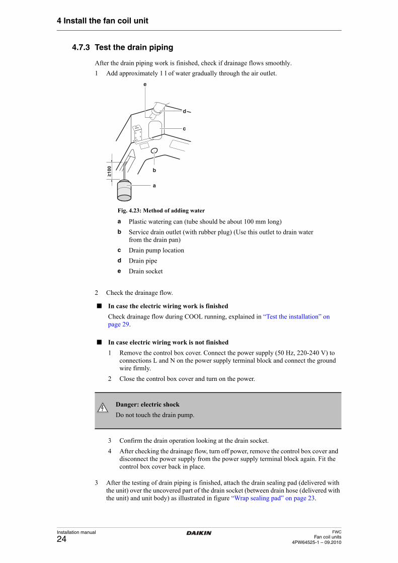
After the drain piping work is finished, check if drainage flows smoothly.
1 Add approximately 1 l of water gradually through the air outlet.
Fig. 4.23: Method of adding water
2 Check the drainage flow.
3 After the testing of drain piping is finished, attach the drain sealing pad (delivered with the unit) over the uncovered part of the drain socket (between drain hose (delivered with the unit) and unit body) as illustrated in figure “Wrap sealing pad” on page 23.
Install optional equipment
�100
d
c
a
b
e
a Plastic watering can (tube should be about 100 mm long)
b Service drain outlet (with rubber plug) (Use this outlet to drain water from the drain pan)
c Drain pump location
d Drain pipe
e Drain socket
■ In case the electric wiring work is finished
Check drainage flow during COOL running, explained in “Test the installation” on page 29.
■ In case electric wiring work is not finished
1 Remove the control box cover. Connect the power supply (50 Hz, 220-240 V) to connections L and N on the power supply terminal block and connect the ground wire firmly.
2 Close the control box cover and turn on the power.
Danger: electric shock
Do not touch the drain pump.
3 Confirm the drain operation looking at the drain socket.
4 After checking the drainage flow, turn off power, remove the control box cover and disconnect the power supply from the power supply terminal block again. Fit the control box cover back in place.
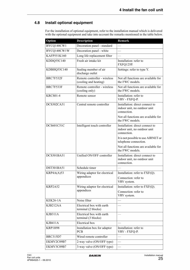
FWCFan coil units4PW64525-1 – 09.2010
Installation manual
25
4 Install the fan coil unit
4.8 Install optional equipment
For the installation of optional equipment, refer to the installation manual which is delivered with the optional equipment and take into account the remarks mentioned in the table below.
Option Description Remark
BYCQ140CW1 Decoration panel - standard —
BYCQ140CW1W Decoration panel - white —
KAFP551K160 Long life replacement filter —
KDDQ55C140 Fresh air intake kit Installation: refer toFXFQ125P.
KDBHQ55C140 Sealing member of air discharge outlet
Settings: refer to type Y.
BRC7F532F Remote controller - wireless (cooling and heating)
Not all functions are available for the FWC models.
BRC7F533F Remote controller - wireless (cooling only)
Not all functions are available for the FWC models.
KRCS01-4 Remote sensor Installation: refer to VRV - FXFQ-P.
DCS302CA51 Central remote controller Installation: direct connect to indoor unit, no outdoor unit connection.
Not all functions are available for the FWC models.
DCS601C51C Intelligent touch controller Installation: direct connect to indoor unit, no outdoor unit connection.
It is not possible to use AIRNET or telephone connection.
Not all functions are available for the FWC models.
DCS301BA51 Unified ON/OFF controller Installation: direct connect to indoor unit, no outdoor unit connection.
DST301BA51 Schedule timer —
KRP4A(A)53 Wiring adaptor for electrical appendices
Installation: refer to FXF(Q).
Connection: refer toVRV system.
KRP2A52 Wiring adaptor for electrical appendices
Installation: refer to FXF(Q).
Connection: refer to VRV system.
KEK26-1A Noise filter —
KJB212AA Electrical box with earth terminal (2 blocks)
—
KJB311A Electrical box with earth terminal (3 blocks)
—
KJB411A Electrical box —
KRP1H98 Installation box for adaptor PCB
Installation: refer to VRV - FXFQ-P.
BRC315D7 Wired remote controller —
EKMV2C09B7 2-way valve (ON/OFF type) —
EKMV3C09B7 3-way valve (ON/OFF type) —
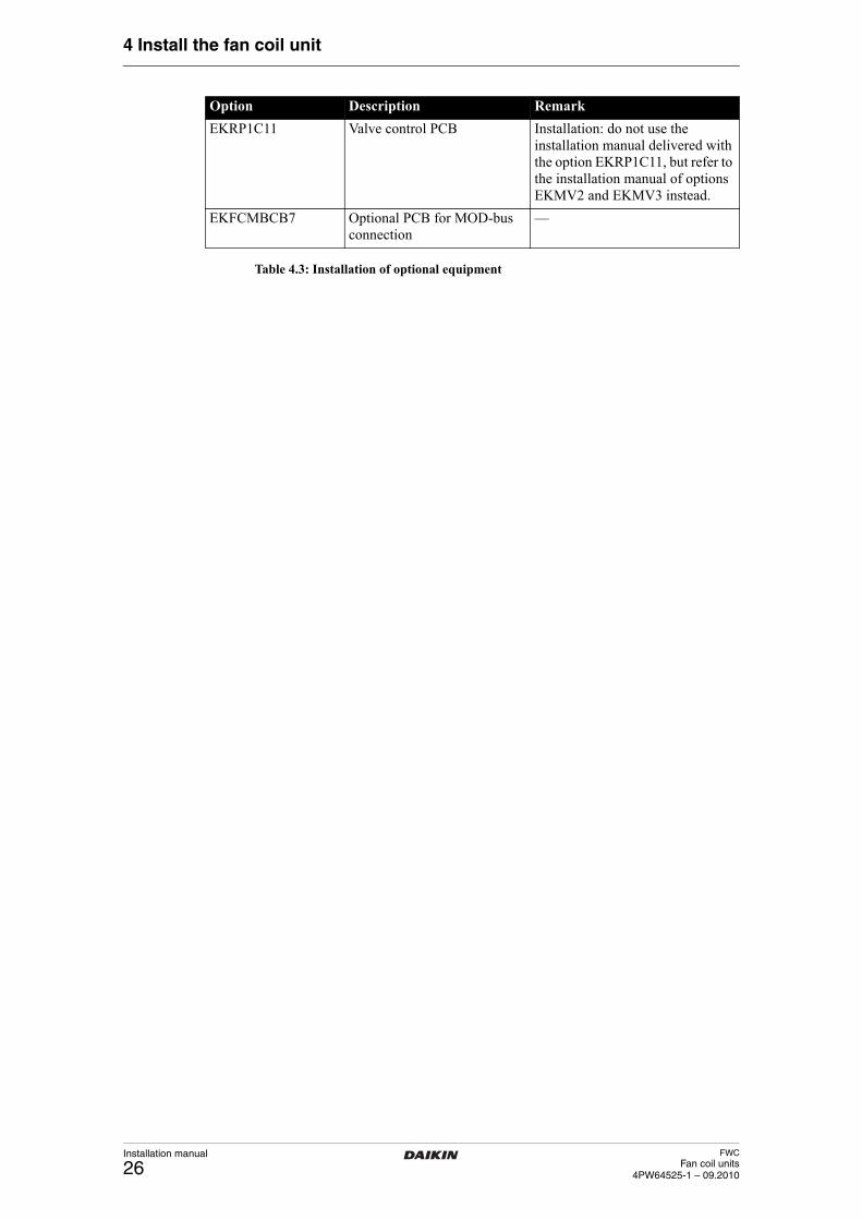
Installation manual
26FWC
Fan coil units4PW64525-1 – 09.2010
4 Install the fan coil unit
Table 4.3: Installation of optional equipment
EKRP1C11 Valve control PCB Installation: do not use the installation manual delivered with the option EKRP1C11, but refer to the installation manual of options EKMV2 and EKMV3 instead.
EKFCMBCB7 Optional PCB for MOD-bus connection
—
Option Description Remark
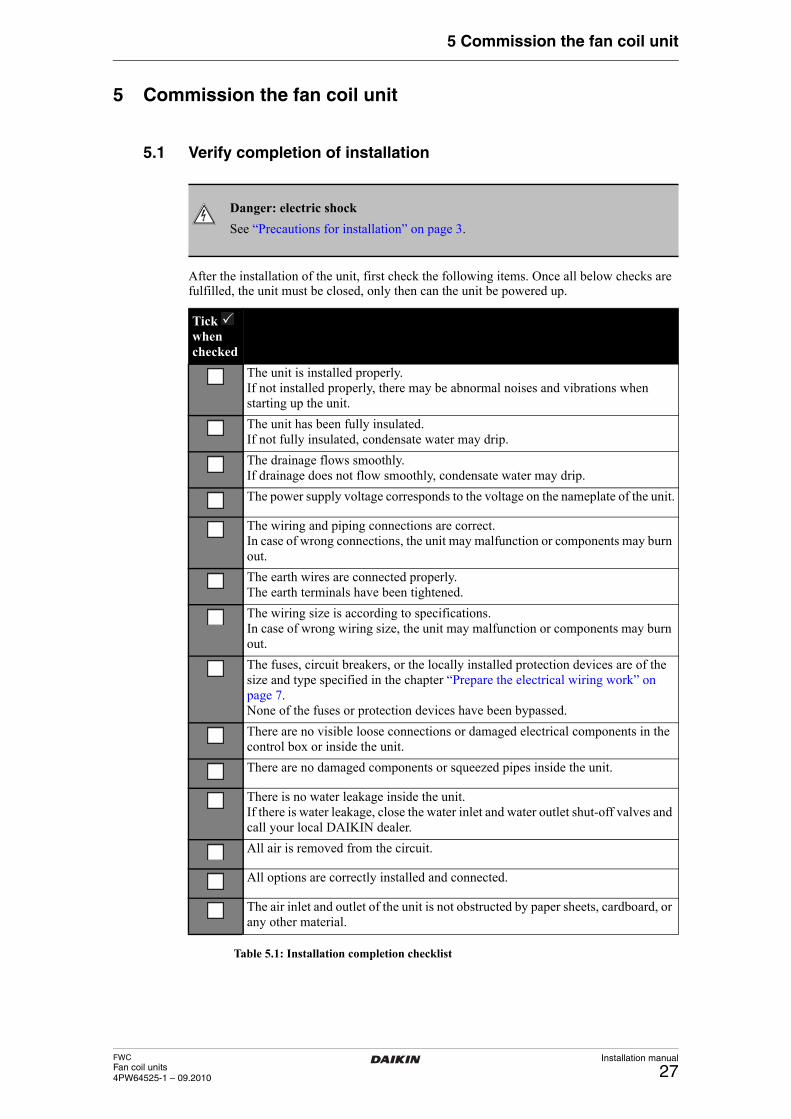
FWCFan coil units4PW64525-1 – 09.2010
Installation manual
27
5 Commission the fan coil unit
5 Commission the fan coil unitVerify completion of installation
5.1 Verify completion of installation
After the installation of the unit, first check the following items. Once all below checks are fulfilled, the unit must be closed, only then can the unit be powered up.
Table 5.1: Installation completion checklist
Danger: electric shock
See “Precautions for installation” on page 3.
Tick when checked
The unit is installed properly. If not installed properly, there may be abnormal noises and vibrations when starting up the unit.
The unit has been fully insulated.If not fully insulated, condensate water may drip.
The drainage flows smoothly.If drainage does not flow smoothly, condensate water may drip.
The power supply voltage corresponds to the voltage on the nameplate of the unit.
The wiring and piping connections are correct.In case of wrong connections, the unit may malfunction or components may burn out.
The earth wires are connected properly.The earth terminals have been tightened.
The wiring size is according to specifications.In case of wrong wiring size, the unit may malfunction or components may burn out.
The fuses, circuit breakers, or the locally installed protection devices are of the size and type specified in the chapter “Prepare the electrical wiring work” on page 7.None of the fuses or protection devices have been bypassed.
There are no visible loose connections or damaged electrical components in the control box or inside the unit.
There are no damaged components or squeezed pipes inside the unit.
There is no water leakage inside the unit. If there is water leakage, close the water inlet and water outlet shut-off valves and call your local DAIKIN dealer.
All air is removed from the circuit.
All options are correctly installed and connected.
The air inlet and outlet of the unit is not obstructed by paper sheets, cardboard, or any other material.
�
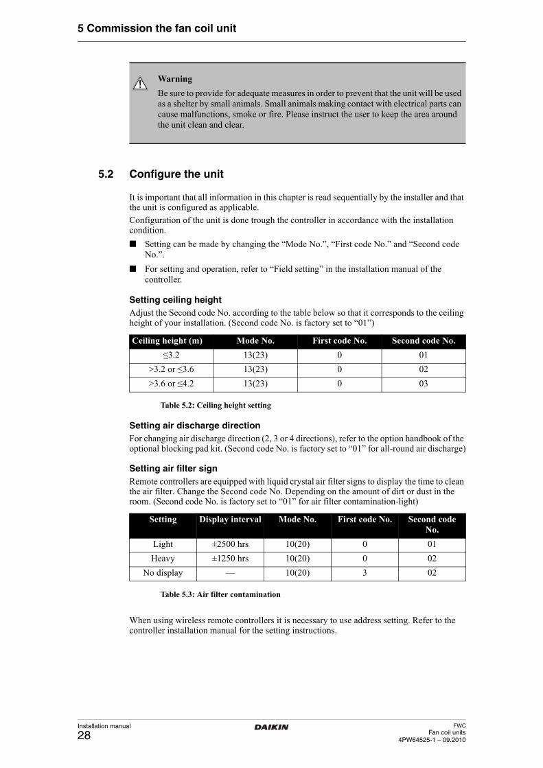
Installation manual
28FWC
Fan coil units4PW64525-1 – 09.2010
5 Commission the fan coil unit
Configure the unit
5.2 Configure the unit
It is important that all information in this chapter is read sequentially by the installer and that the unit is configured as applicable.
Configuration of the unit is done trough the controller in accordance with the installation condition.
■ Setting can be made by changing the “Mode No.”, “First code No.” and “Second code No.”.
■ For setting and operation, refer to “Field setting” in the installation manual of the controller.
Setting ceiling heightAdjust the Second code No. according to the table below so that it corresponds to the ceiling height of your installation. (Second code No. is factory set to “01”)
Table 5.2: Ceiling height setting
Setting air discharge directionFor changing air discharge direction (2, 3 or 4 directions), refer to the option handbook of the optional blocking pad kit. (Second code No. is factory set to “01” for all-round air discharge)
Setting air filter signRemote controllers are equipped with liquid crystal air filter signs to display the time to clean the air filter. Change the Second code No. Depending on the amount of dirt or dust in the room. (Second code No. is factory set to “01” for air filter contamination-light)
Table 5.3: Air filter contamination
When using wireless remote controllers it is necessary to use address setting. Refer to the controller installation manual for the setting instructions.
Warning
Be sure to provide for adequate measures in order to prevent that the unit will be used as a shelter by small animals. Small animals making contact with electrical parts can cause malfunctions, smoke or fire. Please instruct the user to keep the area around the unit clean and clear.
Ceiling height (m) Mode No. First code No. Second code No.
≤3.2 13(23) 0 01
>3.2 or ≤3.6 13(23) 0 02
>3.6 or ≤4.2 13(23) 0 03
Setting Display interval Mode No. First code No. Second code No.
Light ±2500 hrs 10(20) 0 01
Heavy ±1250 hrs 10(20) 0 02
No display — 10(20) 3 02
FWCFan coil units4PW64525-1 – 09.2010
Installation manual
29
5 Commission the fan coil unit
Activating forced OFF and ON/OFF operationThe following table explains “forced OFF” and “ON/OFF operations” in response to the input signal.
Table 5.4: Forced OFF and ON/OFF operation
1 Turn the power on and then use the remote controller to select operation.
2 Set the remote controller to the field set mode.
Table 5.5: Forced OFF and ON/OFF selectionTest the installation
5.3 Test the installation
After installation, the installer is obliged to verify correct operation. Therefore a test run must be performed according to the procedures described below.
In case something is wrong with the unit and it does not operate, contact your local DAIKIN dealer.
Test operation before installing decoration panel
1 Open the water inlet valve(s).
2 Open the water outlet valve(s).
3 Set to cooling operation with the remote controller and start operation by pushing ON/OFF button.
4 Press Inspection/Test Operation button 4 times and operate at Test Operation mode for 3 minutes.
5 Press Inspection/Test Operation button and operate normally.
6 Confirm function of unit according to the operation manual.
7 Turn off the main power supply after operation.
Forced OFF ON/OFF operations Protective equipment input
Input “ON” stops operation Input OFF→ON: turns on the unit (impossible by remote controllers)
Input ON: enables abnormal system stop (an error code will be displayed)
Input “OFF” enables control Input ON→OFF: turns off the unit (by remote controller)
Input OFF: enables normal operation
Setting Mode No. First code No. Second code No.
Forced OFF 12(22) 8 01
ON/OFF operation 12(22) 8 02
Protective equipment input
12(22) 8 03
Information
When using a wireless remote controller, conduct a test operation after installing the decoration panel.
Danger: electric shock
See “Precautions for installation” on page 3.
Installation manual
30FWC
Fan coil units4PW64525-1 – 09.2010
5 Commission the fan coil unit
Test operation after installing decoration panel
1 Open the water inlet valve(s).
2 Open the water outlet valve(s).
3 Set to cooling operation with the remote controller and start operation by pushing ON/OFF button.
4 Press Inspection/Test Operation button 4 times (2 times for wireless remote controller) and operate at Test Operation mode for 3 minutes.
5 Push air flow direction adjust button to make sure the unit is in operation.
6 Press Inspection/Test Operation button and operate normally.
7 Confirm function of unit according to the operation manual.Handover to the user
5.4 Handover to the user
Once the test run is finished and the unit operates properly, fill in the sheet “Handover of the installation to the user” which is an annex of the user manual.
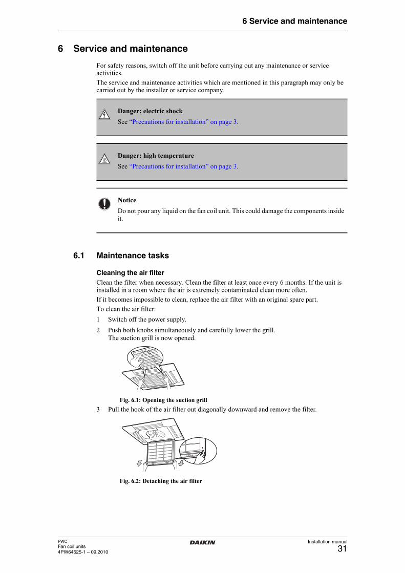
FWCFan coil units4PW64525-1 – 09.2010
Installation manual
31
6 Service and maintenance
6 Service and maintenance
For safety reasons, switch off the unit before carrying out any maintenance or service activities.
The service and maintenance activities which are mentioned in this paragraph may only be carried out by the installer or service company.
Maintenance tasks
6.1 Maintenance tasks
Cleaning the air filterClean the filter when necessary. Clean the filter at least once every 6 months. If the unit is installed in a room where the air is extremely contaminated clean more often.
If it becomes impossible to clean, replace the air filter with an original spare part.
To clean the air filter:
1 Switch off the power supply.
2 Push both knobs simultaneously and carefully lower the grill.The suction grill is now opened.
Fig. 6.1: Opening the suction grill
3 Pull the hook of the air filter out diagonally downward and remove the filter.
Fig. 6.2: Detaching the air filter
Danger: electric shock
See “Precautions for installation” on page 3.
Danger: high temperature
See “Precautions for installation” on page 3.
Notice
Do not pour any liquid on the fan coil unit. This could damage the components inside it.
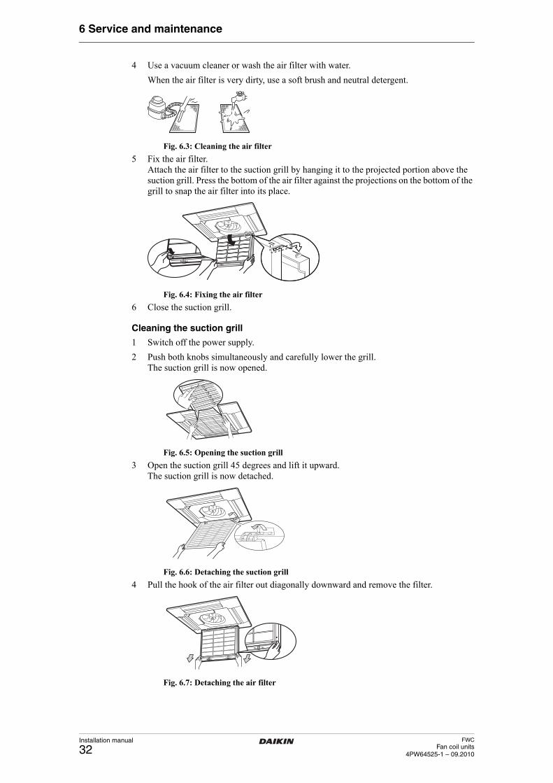
Installation manual
32FWC
Fan coil units4PW64525-1 – 09.2010
6 Service and maintenance
4 Use a vacuum cleaner or wash the air filter with water.
When the air filter is very dirty, use a soft brush and neutral detergent.
Fig. 6.3: Cleaning the air filter
5 Fix the air filter. Attach the air filter to the suction grill by hanging it to the projected portion above the suction grill. Press the bottom of the air filter against the projections on the bottom of the grill to snap the air filter into its place.
Fig. 6.4: Fixing the air filter
6 Close the suction grill.
Cleaning the suction grill
1 Switch off the power supply.
2 Push both knobs simultaneously and carefully lower the grill.The suction grill is now opened.
Fig. 6.5: Opening the suction grill
3 Open the suction grill 45 degrees and lift it upward. The suction grill is now detached.
Fig. 6.6: Detaching the suction grill
4 Pull the hook of the air filter out diagonally downward and remove the filter.
Fig. 6.7: Detaching the air filter
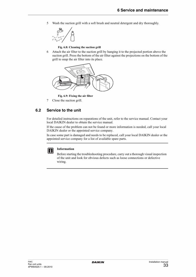
FWCFan coil units4PW64525-1 – 09.2010
Installation manual
33
6 Service and maintenance
5 Wash the suction grill with a soft brush and neutral detergent and dry thoroughly.
Fig. 6.8: Cleaning the suction grill
6 Attach the air filter to the suction grill by hanging it to the projected portion above the suction grill. Press the bottom of the air filter against the projections on the bottom of the grill to snap the air filter into its place.
Fig. 6.9: Fixing the air filter
7 Close the suction grill.Service to the unit
6.2 Service to the unit
For detailed instructions on reparations of the unit, refer to the service manual. Contact your local DAIKIN dealer to obtain the service manual.
If the cause of the problem can not be found or more information is needed, call your local DAIKIN dealer or the appointed service company.
In case some part is damaged and needs to be replaced, call your local DAIKIN dealer or the appointed service company for a list of available spare parts.
Information
Before starting the troubleshooting procedure, carry out a thorough visual inspection of the unit and look for obvious defects such as loose connections or defective wiring.
Installation manual
34FWC
Fan coil units4PW64525-1 – 09.2010
7 Glossary
7 Glossary
Term Meaning
Accessories: Equipment which is delivered with the unit and which needs to be installed according to the instructions in the documentation
Air filter: Device composed of fibrous materials which removes solid particulates such as dust, pollen, mould and bacteria from the air
Applicable legislation:
All international, European, national and local directives, laws, regulations and/or codes which are relevant and applicable for a certain product or domain
Circuit breaker (fuse):
Safety device used in electrical installations to prevent electric shock
Coil (heat exchanger):
Main component of a fan coil unit. Receives hot or cold water from a heat source
Controller: Device to configure and operate the fan coil unit
Dealer Sales distributor for fan coil units and other DAIKIN products
Fan: Main component of a fan coil unit. Spreads heat or coolness in a space
Fan coil unit: Heating and cooling product
Field supply: Equipment which needs to be installed according to instructions in this manual, but which are not supplied by DAIKIN
Air inlet/outlet: Fan coil units have an air inlet and air outlet for providing air circulation
Installer: Technical skilled person who is qualified to install fan coil units and other DAIKIN products
Optional equipment:
Equipment which can optionally be combined to the fan coil unit
Water inlet/outlet: Fan coil units have a water inlet and water outlet for connection to the water circuit.
Service company: Qualified company which can perform or coordinate the required service to the fan coil unit
User: Person who is owner of the fan coil unit and/or operates the product
NOTES

Cop
yrig
ht 2
010
Dai
kin
4PW64525-1 09.2010


