
INSTALLATION &SERVICE MANUAL
MODELSSF-46 * SF-47 * SF-48
SERIESREMOTE DISPENSERS(single and dual hose models)
Pump Measure Control, Inc.1070 Nine North Drive, Suite 100
Alpharetta, GA 30004
Phone (770) 667-0667Fax (770) 667-0476
ETL Listed

Page 1
Table of Contents
Section 1 - Installation………………………………………………………………………………………………. 3 Piping……………………………………………………………………………………………….. 3 Electrical……………………………………………………………………………….…………... 4 Start-Up………………………………..……………………………………………………..…….. 4 Programming……………………………………………………………………………………………. 5 Operation………………………………………………………………………………………………... 7 Maintenance…………………………………………………………………………………………….. 7 Dispenser Calibration - SF-46……….………………………………………………………………….. 8 Dispenser Calibration - SF-47 / SF-48………………………………………………………………….. 9 Section 2 - Parts SF-46 Parts List...…………...………………………………………………………………………….. 11 SF-47 Parts List…………..……………………………………………………………………………... 12 SF-48 Parts List……….…….…………………………………………………………………………... 13 Switch Assembly - Exploded Parts View. ……………………………………………………………… 15 2PM-6 - Exploded Parts View………….………………...……………………………………………... 16 2PM-6 - Parts List……………………………………………………………………………………….. 17 M5-P1- Exploded Parts View…………………………………………………………………………… 19 M5-P1 - Parts List………………………………………………………………………………………. 22 Section 3 - Component Information ASCO 8016G Series Solenoid Coil…………………………………………………………………...… 25 ASCO 8210 Series Solenoid Body……………………………………………………………………… 29 Veeder-Root 787181-327 Pulser……………………………………………………………………...… 35 Section 4 - Technical Data Super Flow Dispenser Control………………………………………………………………………….. 39 91-98G07.2 - Internal dispenser wiring as shipped from factory………………………………………. 41 91-04G46.2 - Recommended dispenser wiring when used with TMS 800F Console………….………. 43 91-00A24 - CPU Wiring Terminal Descriptions……………………………………………………..… 45 91-00A25 - CPU Indicator LED Descriptions………………………………………………………….. 47 CPU Functional Wiring Diagram……………………………………………………………………..… 49 Appendix A - Optional Communications Interface 120040-SF Communications Interface Board………………………………………………………….. 51 91-08G271 - 120040x Programming Jumper Settings…………………………..……………………... 53 91-09G157 - Superflow Dispenser wiring to RS-485 Comm D-Box…………………………………... 55

Page 2
Page 3
IMPORTANT Examine the shipment immediately on arrival to ensure there has been no damage or loss in transit. Pump Measure Control, Inc. (PMC), as shipper, is not liable for the hazards of transportation. Read all instructions and tags concerning the dispenser carefully and entirely before starting the installation. An improperly installed dispenser is dangerous and is likely to be a source of ongoing problems. This manual covers the single hose and dual hose versions of the Superflow dispensers. Portions of this man-ual that refer exclusively to one version or the other are indicated.
Installation All PMC dispensers must be installed according to all applicable NEC, NFPA and local codes. The installa-tion portion of this manual is intended to provide some points to watch for when designing and installing the system the dispenser is to operate with. It is the responsiblility of the installer and end customer to ensure that the entire system (tanks, pumps, dispensers, etc.) is designed and installed correctly. A. Piping
B. Electrical Wiring
1. The remote dispensers equipped with a hose reel must be fed product through a system that will maintain near operating pressure on the dispensers when the pump is off. Many submersible pump-ing systems provide this capability as part of the device. However, if a pumping unit is used that does not maintain pressure, a check valve with thermal relief must be installed at the outlet of the pump. The check valve should be spring loaded to provide a good positive seal.
2. Each dispensers should be installed over a sump with provision to mount a LISTED emergency shut off valve. The shut-off valve is installed to stop the flow of fuel to the dispenser in the event of fire or if the dis-penser is knocked off the island.
3. Dispensers should be located as close to the supply tank as possible. Supply lines should be sized to allow simultaneous maximum flow desired for all dispensers fed from it.
4. The vertical supply riser must be cut to the proper height in order to avoid undue stress on the dis-penser when installing the ground joint union. Attach dispenser base to the sump/impact box using the anchor points.
5. When the dispenser has been connected to the piping, the lines should be tested for leaks. Remem-ber to allow any fresh pipe compound used in threaded joints to cure or set before performing the leak tests.
6. All hoses used with the dispensers shall be sufficiently reinforced as to not affect the operation or accuracy of the units through its expansion and contraction from pressure.
7. If dispenser is used with a hose reel, the hose should not exceed 50 feet in length.
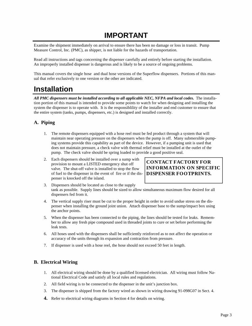
CONTACT FACTORY FOR INFORMATION ON SPECIFIC DISPENSER FOOTPRINTS.
1. All electrical wiring should be done by a qualified licensed electrician. All wiring must follow Na-tional Electrical Code and satisfy all local rules and regulations.
2. All field wiring is to be connected to the dispenser in the unit’s junction box.
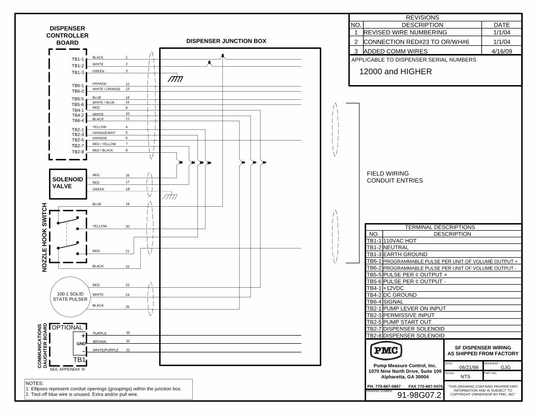
3. The dispenser is shipped from the factory wired as shown in wiring drawing 91-098G07 in Sect. 4.
4. Refer to electrical wiring diagrams in Section 4 for details on wiring.
Page 4
C. Start-Up
1. Make sure all filtration and / or strainers are in place prior to filling the piping system with product.
Any loose debris in the piping must be prevented from passing through the meter where it can cause damage. The SF-40 series dispensers have a 40-mesh strainer on the inlet to the meter.
2. IT IS IMPORTANT TO BLEED THE AIR FROM THE LINES VERY SLOWLY. RUNNING THE METER RPM UP ON AIR PUSHED THROUGH THE SUPPLY LINE AHEAD OF THE PRODUCT CAN CAUSE SEVER, AND OFTEN TOTAL, DAMAGE TO THE ME-TER.
3. After all air has been removed from the supply piping, run 15 to 20 gallons of product through the dispenser to com-pletely fill the system and discharge all air from the unit.
4. Although the dispensers are shipped from the factory prop-erly adjusted, rough handling in transit or special installa-tion conditions can alter this. Before the dispensers are placed into service, their calibration should be verified and any necessary changes made. Refer to the section detailing dispenser calibration.
5. Before placing unit in service, verify that all displays and the totalizer are functioning properly.
6. The displays on the dispensers are backed up by a 6V- 4AH lead acid gel-cell battery located in the head. The battery is located inside the rear cover of the dispenser head, on the left side. The battery is shipped fully charged, but disconnected. Before placing the dispenser in service, the battery must be reconnected. To do this, reconnect the red/yellow wire tied to the side of the battery to the bat-tery’s positive(+) terminal. The battery is recharged while the AC power to the dispenser is on. If there is a power failure, the battery will supply power to keep information on the displays for a mini-mum of 15 minutes.
BLEED THE AIR FROM THE LINES VERY SLOWLY. ALLOWING THE METER TO REACH EXCESSIVE RPM CAN CAUSE SEVER DAMAGE.
IMPORTANT
Page 5
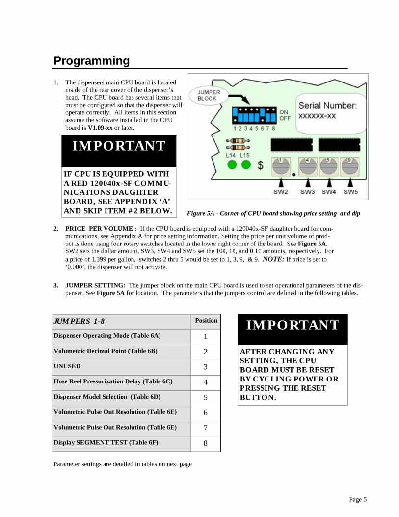
1. The dispensers main CPU board is located inside of the rear cover of the dispenser’s head. The CPU board has several items that must be configured so that the dispenser will operate correctly. All items in this section assume the software installed in the CPU board is V1.09-xx or later.
2. PRICE PER VOLUME : If the CPU board is equipped with a 120040x-SF daughter board for com-munications, see Appendix A for price setting information. Setting the price per unit volume of prod-uct is done using four rotary switches located in the lower right corner of the board. See Figure 5A. SW2 sets the dollar amount, SW3, SW4 and SW5 set the 10¢, 1¢, and 0.1¢ amounts, respectively. For a price of 1.399 per gallon, switches 2 thru 5 would be set to 1, 3, 9, & 9. NOTE: If price is set to ‘0.000’, the dispenser will not activate.
Figure 5A - Corner of CPU board showing price setting and dip
Programming
AFTER CHANGING ANY SETTING, THE CPU BOARD MUST BE RESET BY CYCLING POWER OR PRESSING THE RESET BUTTON.
IMPORTANT
3. JUMPER SETTING: The jumper block on the main CPU board is used to set operational parameters of the dis-penser. See Figure 5A for location. The parameters that the jumpers control are defined in the following tables.
JUMPERS 1-8 Position
Dispenser Operating Mode (Table 6A) 1
Volumetric Decimal Point (Table 6B) 2
UNUSED 3
Hose Reel Pressurization Delay (Table 6C) 4
Dispenser Model Selection (Table 6D) 5
Volumetric Pulse Out Resolution (Table 6E) 6
Volumetric Pulse Out Resolution (Table 6E) 7
Display SEGMENT TEST (Table 6F) 8
Parameter settings are detailed in tables on next page
IF CPU IS EQUIPPED WITH A RED 120040x-SF COMMU-NICATIONS DAUGHTER BOARD, SEE APPENDIX ‘A’ AND SKIP ITEM #2 BELOW.
IMPORTANT
Page 6
JUM
PE
R S
ET
TIN
GS
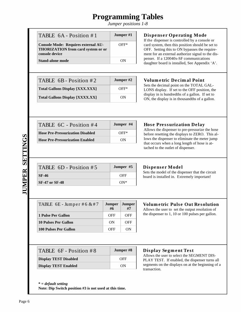
Programming Tables Jumper positions 1-8
TABLE 6B - Position #2 Jumper #2
Total Gallons Display [XXX.XXX] OFF*
Total Gallons Display [XXXX.XX] ON
TABLE 6C - Position #4 Jumper #4
Hose Pre-Pressurization Disabled OFF*
Hose Pre-Pressurization Enabled ON
TABLE 6A - Position #1 Jumper #1
Console Mode: Requires external AU-THORIZATION from card system or or console device
OFF*
Stand-alone mode ON
TABLE 6F - Position #8 Jumper #8
Display TEST Disabled OFF
Display TEST Enabled ON
TABLE 6E - Jumper #6 & #7 Jumper #6
Jumper #7
1 Pulse Per Gallon OFF OFF
10 Pulses Per Gallon ON OFF
100 Pulses Per Gallon OFF ON
TABLE 6D - Position #5 Jumper #5
SF-46 OFF
SF-47 or SF-48 ON*
* = default setting Note: Dip Switch position #3 is not used at this time.
Dispenser Operating Mode If the dispenser is controlled by a console or card system, then this position should be set to OFF. Setting this to ON bypasses the require-ment for an external authorize signal to the dis-penser. If a 120040x-SF communications daughter board is installed, See Appendix ‘A’.
Volumetric Decimal Point Sets the decimal point on the TOTAL GAL-LONS display. If set to the OFF position, the display in is hundredths of a gallon. If set to ON, the display is in thousandths of a gallon.
Dispenser Model Sets the model of the dispenser that the circuit board is installed in. Extremely important!
Volumetric Pulse Out Resolution Allows the user to set the output resolution of the dispenser to 1, 10 or 100 pulses per gallon.
Display Segment Test Allows the user to select the SEGMENT DIS-PLAY TEST. If enabled, the dispenser turns all segments on the displays on at the beginning of a transaction.
Hose Pressurization Delay Allows the dispenser to pre-pressurize the hose before resetting the displays to ZERO. This al-lows the dispenser to eliminate the meter jump that occurs when a long length of hose is at-tached to the outlet of dispenser.
Page 7
1. To start the dispenser, simply remove the nozzle from its boot and lift the ON/OFF lever that it rested on. If the dispenser is stand alone or is authorized to dispense by a control system, the dispenser will reset and be ready to dispense.
2. After delivery is complete, the ON/OFF lever is pushed down and the nozzle returned to its boot. This will end the transaction.
3. During delivery, TOTAL SALE and VOLUME delivered will be displayed on the face of the dispenser. At the completion of a transaction, this information will remain on the displays until the next transaction is started.
4. During delivery, the CPU board in the dispenser will generate two real time output pulse streams for use by remote devices. One pulse stream represents volume dispensed and its resolution can be set by the user. See Programming section. The second pulse stream is a pulse per penny. For every one cent shown on the TOTAL SALE display, a pulse will have been sent out in this stream. The pulse output drivers are open-collector type. See Super Flow Dispenser Control in Section 4.
Operation
Maintenance The SF-40 series dispensers are designed to give many years of trouble free service. However, like any me-chanical device, they require periodic maintenance to prevent problems from developing. 1. The SF-47 and SF-48 dispensers come equipped with an inlet
strainer just upstream of the meter. The stainless steel strainer basket located in the strainer housing should be cleaned periodi-cally to remove debris. To clean the strainer basket, remove the end cap from the strainer housing and pull the basket out. While cleaning the basket, check for any holes or tears in the screen that may allow debris to pass and damage the meter. If any are found, the screen should be replaced as soon as possible. Contact the factory for replacement parts.
2. The battery used to backup the displays in the dispenser should be replaced annually.
3. While doing any maintenance on the dispenser, check the hose for any cracks or tears that can cause leaks.
4. Dispensers with integral reels are equipped with grease fittings that must be periodically lubricated. See reel manufacturer’s in-formation included with dispenser for their recommendations on maintenance.
5. When cleaning the exterior of the cabinet, use only non-abrasive, non-corrosive cleaning agents. Use only soft rags.
6. The exterior stainless panels on the SF dispensers should be polished several times a year to maintain ap-pearance of the units. An automotive grade polish works well.
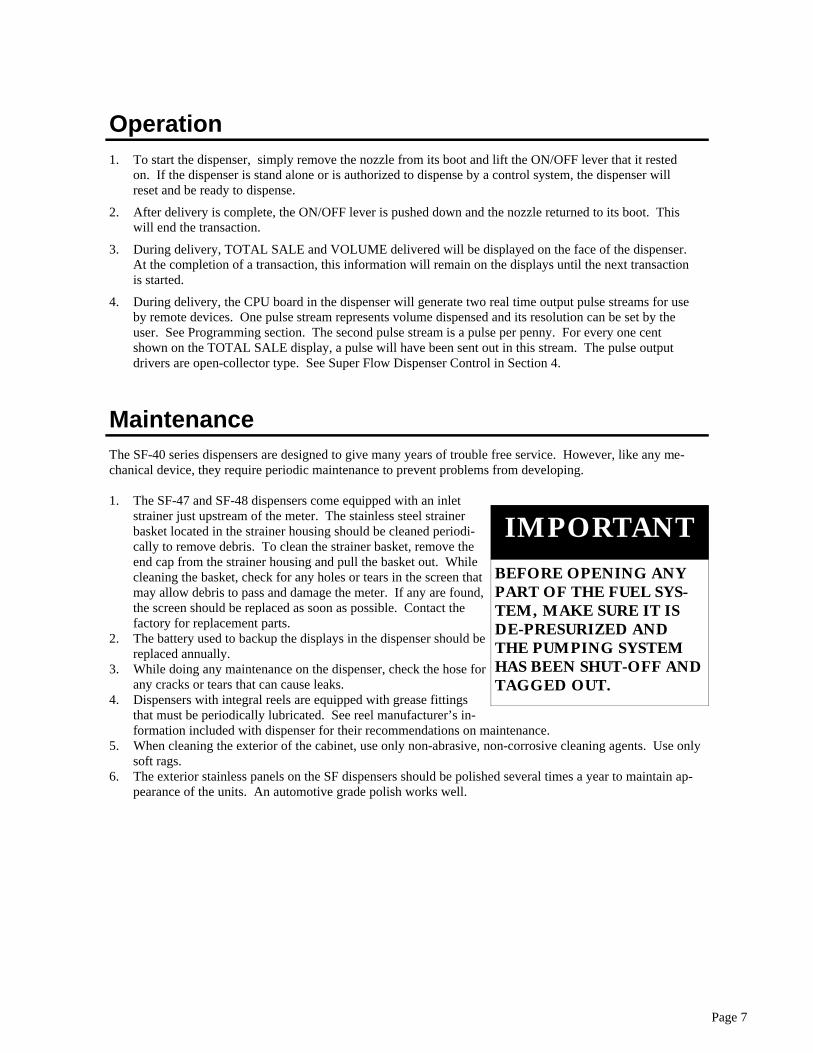
BEFORE OPENING ANY PART OF THE FUEL SYS-TEM, MAKE SURE IT IS DE-PRESURIZED AND THE PUMPING SYSTEM HAS BEEN SHUT-OFF AND TAGGED OUT.
IMPORTANT
Page 8
Dresser-Wayne 2PM-6 Meter The adjuster on the Wayne 2PM-6 meter is accessible by removing the front door on the dispenser. The following steps will allow the calibration to be set on the meter.
1. Check the dispensers current calibration setting by delivering product to a reliable, accurate prover. Perform several delivery tests at normal the flow rate to verify repeatability.
2. Note the volume in the prover.
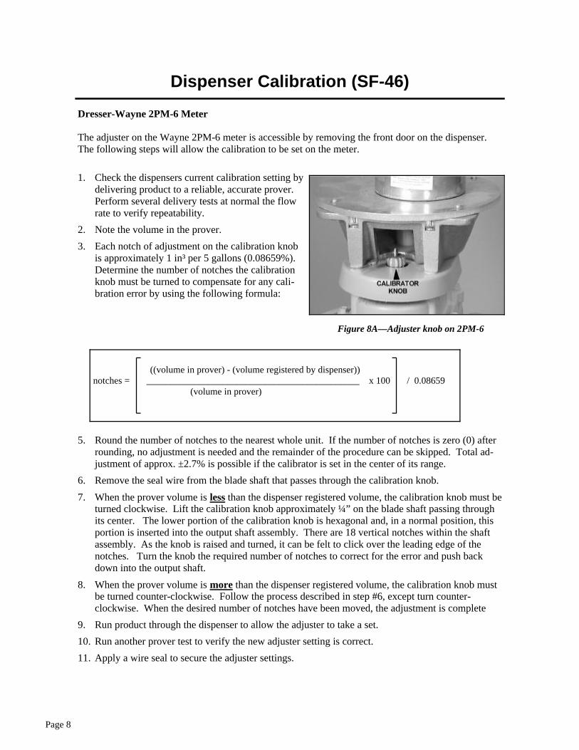
3. Each notch of adjustment on the calibration knob is approximately 1 in³ per 5 gallons (0.08659%). Determine the number of notches the calibration knob must be turned to compensate for any cali-bration error by using the following formula:
5. Round the number of notches to the nearest whole unit. If the number of notches is zero (0) after rounding, no adjustment is needed and the remainder of the procedure can be skipped. Total ad-justment of approx. ±2.7% is possible if the calibrator is set in the center of its range.
6. Remove the seal wire from the blade shaft that passes through the calibration knob.
7. When the prover volume is less than the dispenser registered volume, the calibration knob must be turned clockwise. Lift the calibration knob approximately ¼” on the blade shaft passing through its center. The lower portion of the calibration knob is hexagonal and, in a normal position, this portion is inserted into the output shaft assembly. There are 18 vertical notches within the shaft assembly. As the knob is raised and turned, it can be felt to click over the leading edge of the notches. Turn the knob the required number of notches to correct for the error and push back down into the output shaft.
8. When the prover volume is more than the dispenser registered volume, the calibration knob must be turned counter-clockwise. Follow the process described in step #6, except turn counter-clockwise. When the desired number of notches have been moved, the adjustment is complete
9. Run product through the dispenser to allow the adjuster to take a set.
10. Run another prover test to verify the new adjuster setting is correct.
11. Apply a wire seal to secure the adjuster settings.
Figure 8A—Adjuster knob on 2PM-6
((volume in prover) - (volume registered by dispenser)) notches = _____________________________________________ x 100 / 0.08659 (volume in prover)
Dispenser Calibration (SF-46)
Page 9
Dispenser Calibration (SF-47 & SF-48)
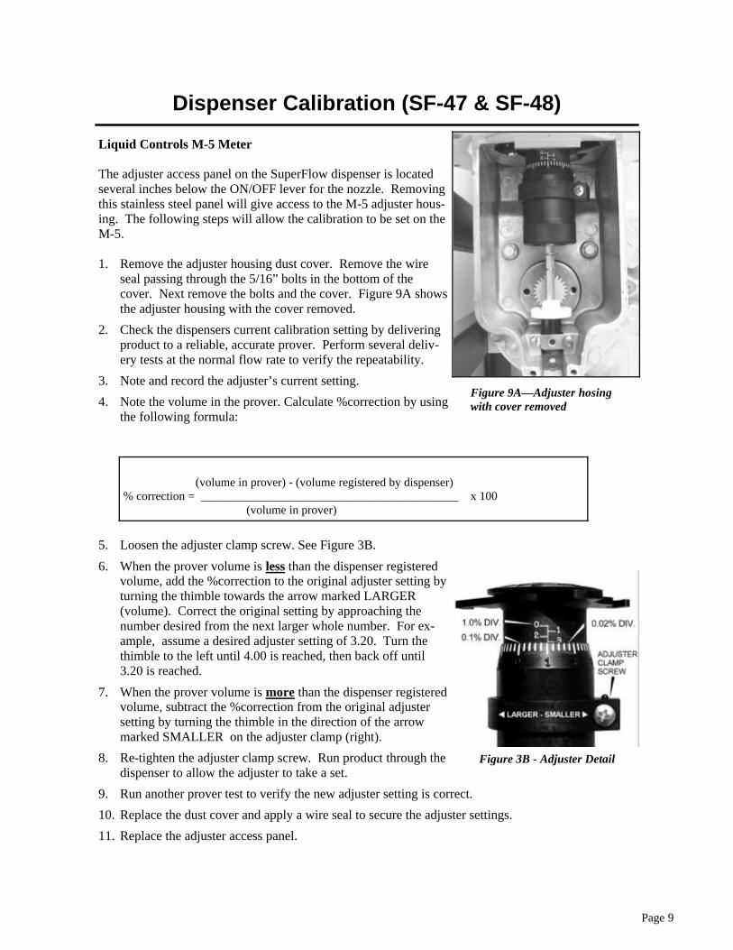
Liquid Controls M-5 Meter The adjuster access panel on the SuperFlow dispenser is located several inches below the ON/OFF lever for the nozzle. Removing this stainless steel panel will give access to the M-5 adjuster hous-ing. The following steps will allow the calibration to be set on the M-5. 1. Remove the adjuster housing dust cover. Remove the wire
seal passing through the 5/16” bolts in the bottom of the cover. Next remove the bolts and the cover. Figure 9A shows the adjuster housing with the cover removed.
2. Check the dispensers current calibration setting by delivering product to a reliable, accurate prover. Perform several deliv-ery tests at the normal flow rate to verify the repeatability.
3. Note and record the adjuster’s current setting.
4. Note the volume in the prover. Calculate %correction by using the following formula:
5. Loosen the adjuster clamp screw. See Figure 3B.
6. When the prover volume is less than the dispenser registered volume, add the %correction to the original adjuster setting by turning the thimble towards the arrow marked LARGER (volume). Correct the original setting by approaching the number desired from the next larger whole number. For ex-ample, assume a desired adjuster setting of 3.20. Turn the thimble to the left until 4.00 is reached, then back off until 3.20 is reached.
7. When the prover volume is more than the dispenser registered volume, subtract the %correction from the original adjuster setting by turning the thimble in the direction of the arrow marked SMALLER on the adjuster clamp (right).
8. Re-tighten the adjuster clamp screw. Run product through the dispenser to allow the adjuster to take a set.
9. Run another prover test to verify the new adjuster setting is correct.
10. Replace the dust cover and apply a wire seal to secure the adjuster settings.
11. Replace the adjuster access panel.
Figure 9A—Adjuster hosing with cover removed
(volume in prover) - (volume registered by dispenser) % correction = ___________________________________________ x 100 (volume in prover)
Figure 3B - Adjuster Detail

Page 10
Page 11
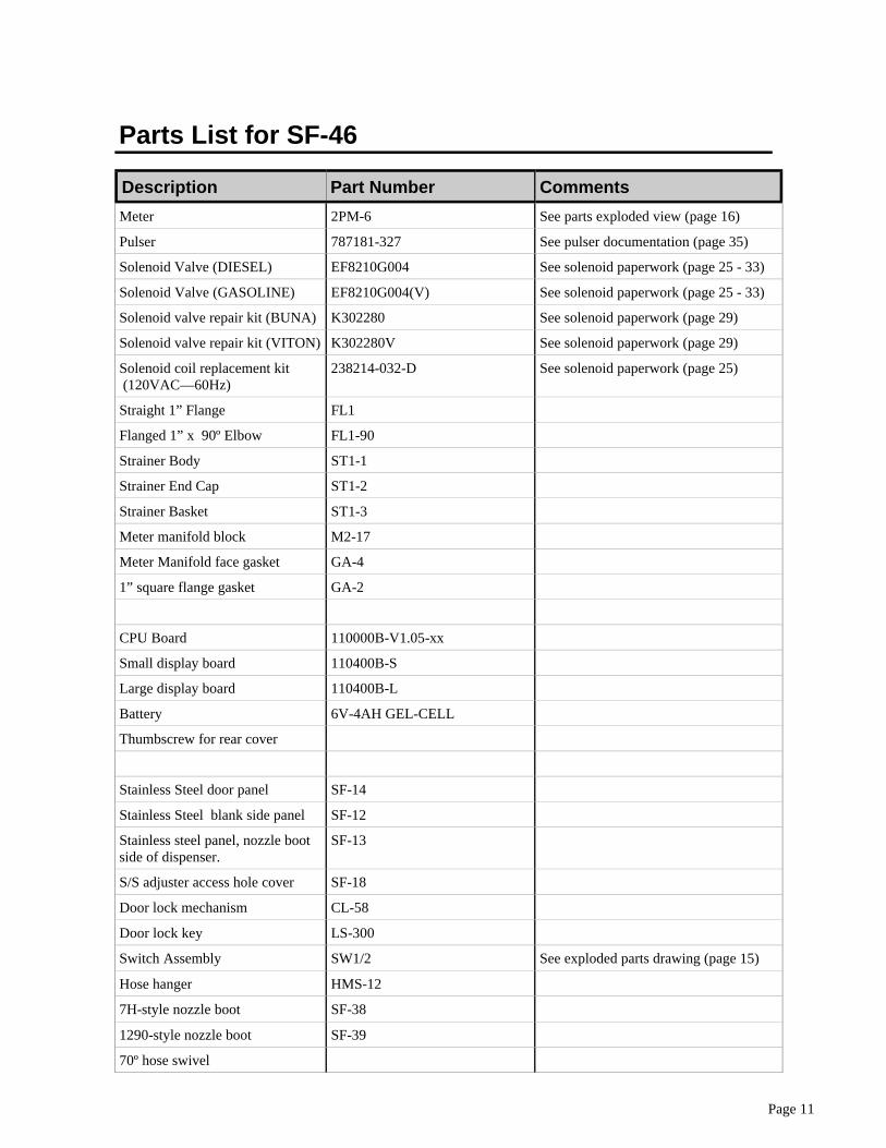
Parts List for SF-46
Description Part Number Comments
Meter 2PM-6 See parts exploded view (page 16)
Pulser 787181-327 See pulser documentation (page 35)
Solenoid Valve (DIESEL) EF8210G004 See solenoid paperwork (page 25 - 33)
Solenoid Valve (GASOLINE) EF8210G004(V) See solenoid paperwork (page 25 - 33)
Solenoid valve repair kit (BUNA) K302280 See solenoid paperwork (page 29)
Solenoid valve repair kit (VITON) K302280V See solenoid paperwork (page 29)
Solenoid coil replacement kit (120VAC—60Hz)
238214-032-D See solenoid paperwork (page 25)
Straight 1” Flange FL1
Flanged 1” x 90º Elbow FL1-90
Strainer Body ST1-1
Strainer End Cap ST1-2
Strainer Basket ST1-3
Meter manifold block M2-17
Meter Manifold face gasket GA-4
1” square flange gasket GA-2
CPU Board 110000B-V1.05-xx
Small display board 110400B-S
Large display board 110400B-L
Battery 6V-4AH GEL-CELL
Thumbscrew for rear cover
Stainless Steel door panel SF-14
Stainless Steel blank side panel SF-12
Stainless steel panel, nozzle boot side of dispenser.
SF-13
S/S adjuster access hole cover SF-18
Door lock mechanism CL-58
Door lock key LS-300
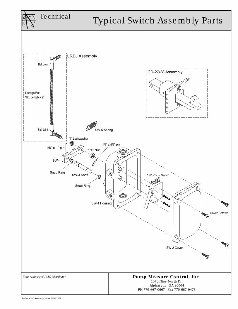
Switch Assembly SW1/2 See exploded parts drawing (page 15)
Hose hanger HMS-12
7H-style nozzle boot SF-38
1290-style nozzle boot SF-39
70º hose swivel
Page 12
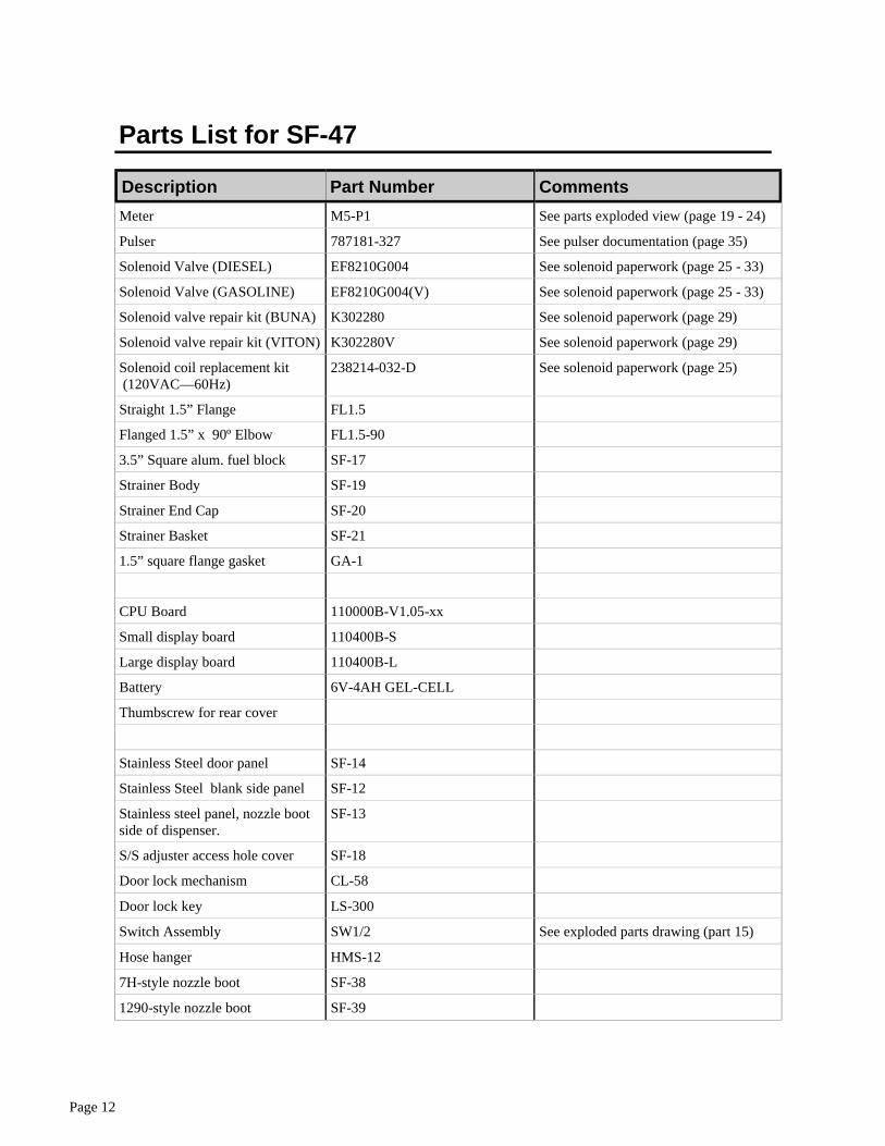
Parts List for SF-47
Description Part Number Comments
Meter M5-P1 See parts exploded view (page 19 - 24)
Pulser 787181-327 See pulser documentation (page 35)
Solenoid Valve (DIESEL) EF8210G004 See solenoid paperwork (page 25 - 33)
Solenoid Valve (GASOLINE) EF8210G004(V) See solenoid paperwork (page 25 - 33)
Solenoid valve repair kit (BUNA) K302280 See solenoid paperwork (page 29)
Solenoid valve repair kit (VITON) K302280V See solenoid paperwork (page 29)
Solenoid coil replacement kit (120VAC—60Hz)
238214-032-D See solenoid paperwork (page 25)
Straight 1.5” Flange FL1.5
Flanged 1.5” x 90º Elbow FL1.5-90
3.5” Square alum. fuel block SF-17
Strainer Body SF-19
Strainer End Cap SF-20
Strainer Basket SF-21
1.5” square flange gasket GA-1
CPU Board 110000B-V1.05-xx
Small display board 110400B-S
Large display board 110400B-L
Battery 6V-4AH GEL-CELL
Thumbscrew for rear cover
Stainless Steel door panel SF-14
Stainless Steel blank side panel SF-12
Stainless steel panel, nozzle boot side of dispenser.
SF-13
S/S adjuster access hole cover SF-18
Door lock mechanism CL-58
Door lock key LS-300
Switch Assembly SW1/2 See exploded parts drawing (part 15)
Hose hanger HMS-12
7H-style nozzle boot SF-38
1290-style nozzle boot SF-39
Page 13
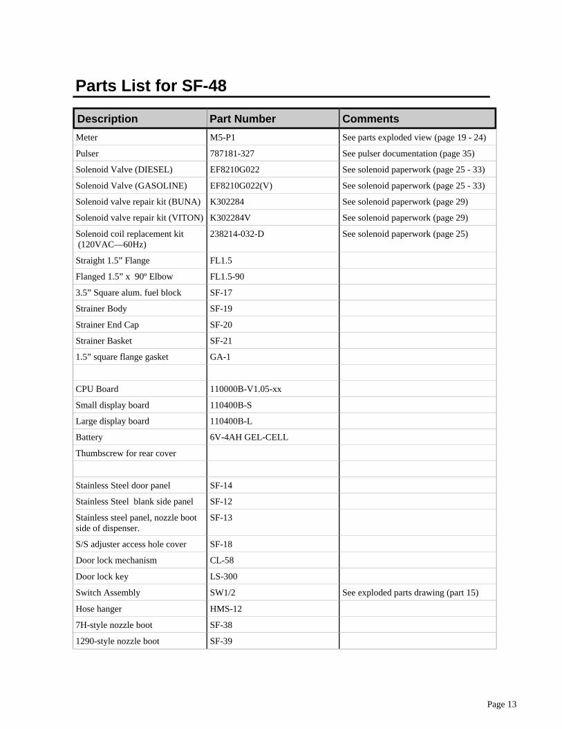
Parts List for SF-48
Description Part Number Comments
Meter M5-P1 See parts exploded view (page 19 - 24)
Pulser 787181-327 See pulser documentation (page 35)
Solenoid Valve (DIESEL) EF8210G022 See solenoid paperwork (page 25 - 33)
Solenoid Valve (GASOLINE) EF8210G022(V) See solenoid paperwork (page 25 - 33)
Solenoid valve repair kit (BUNA) K302284 See solenoid paperwork (page 29)
Solenoid valve repair kit (VITON) K302284V See solenoid paperwork (page 29)
Solenoid coil replacement kit (120VAC—60Hz)
238214-032-D See solenoid paperwork (page 25)
Straight 1.5” Flange FL1.5
Flanged 1.5” x 90º Elbow FL1.5-90
3.5” Square alum. fuel block SF-17
Strainer Body SF-19
Strainer End Cap SF-20
Strainer Basket SF-21
1.5” square flange gasket GA-1
CPU Board 110000B-V1.05-xx
Small display board 110400B-S
Large display board 110400B-L
Battery 6V-4AH GEL-CELL
Thumbscrew for rear cover
Stainless Steel door panel SF-14
Stainless Steel blank side panel SF-12
Stainless steel panel, nozzle boot side of dispenser.
SF-13
S/S adjuster access hole cover SF-18
Door lock mechanism CL-58
Door lock key LS-300
Switch Assembly SW1/2 See exploded parts drawing (part 15)
Hose hanger HMS-12
7H-style nozzle boot SF-38
1290-style nozzle boot SF-39

Page 14
Pump Measure Control, Inc. 1070 Nine North Dr.
Alpharetta, GA 30004 PH 770-667-0667 Fax 770-667-0476
Your Authorized PMC Distributor
Technical Typical Switch Assembly Parts
Bulletin SW Assembly Series 06.01.2001
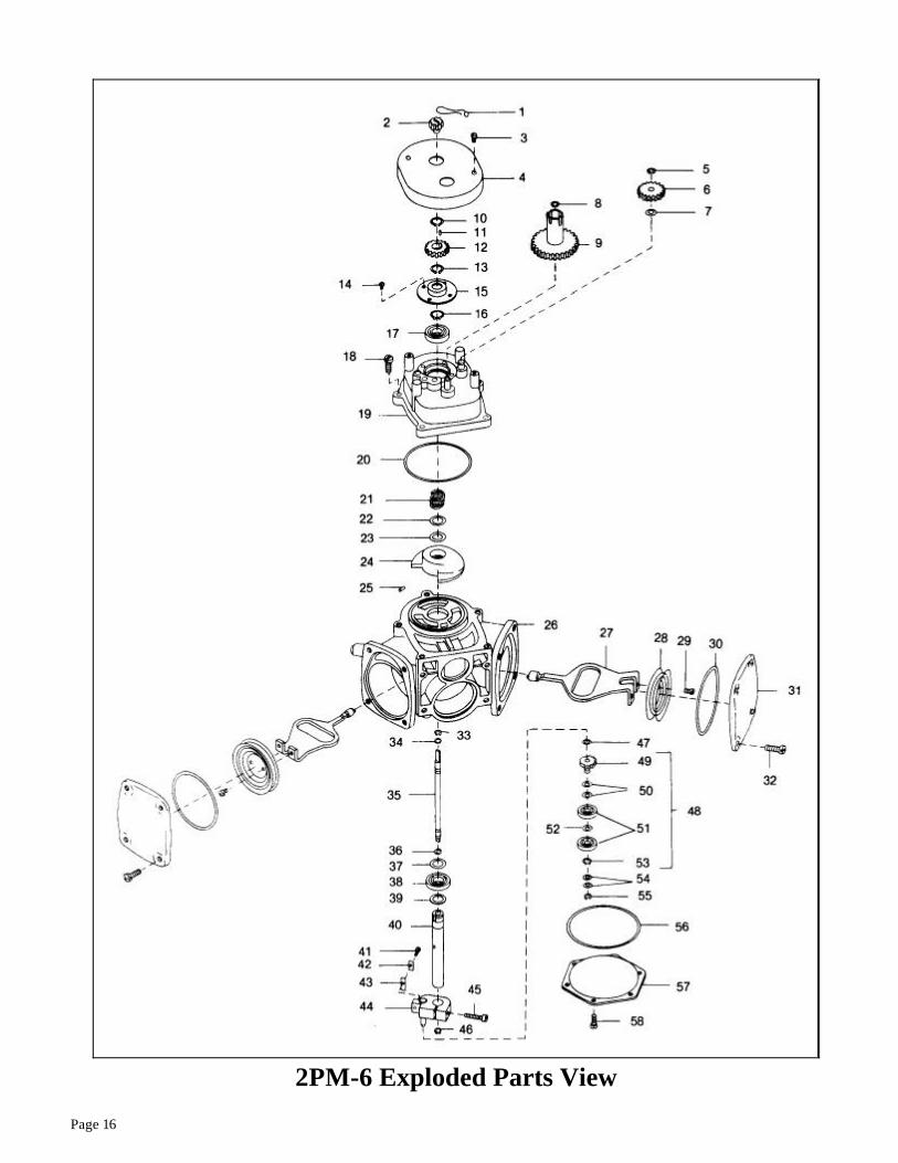
Page 16
2PM-6 Exploded Parts View
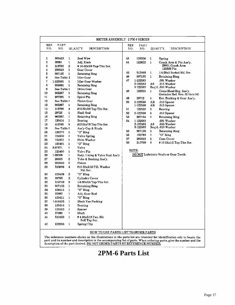
Page 17
2PM-6 Parts List

Page 18

M-5 ®, MA-5 ®
, MA-4®, &
P9560 Series Meters
LIQUIDCONTROLSA Unit of IDEX Corporation
P A R T S M A N U A L
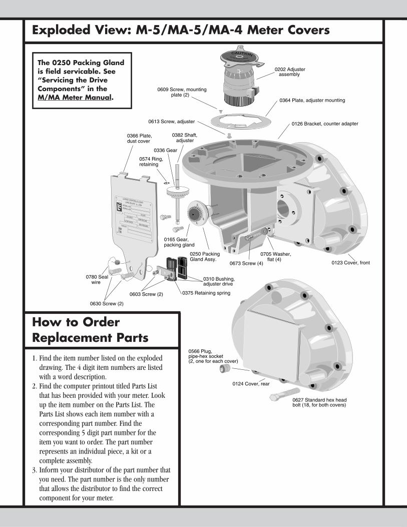
How to OrderReplacement Parts1. Find the item number listed on the exploded
drawing. The 4 digit item numbers are listedwith a word description.
2. Find the computer printout titled Parts List that has been provided with your meter. Lookup the item number on the Parts List. The Parts List shows each item number with a corresponding part number. Find the corresponding 5 digit part number for the item you want to order. The part number represents an individual piece, a kit or a complete assembly.
3. Inform your distributor of the part number thatyou need. The part number is the only numberthat allows the distributor to find the correctcomponent for your meter.
The 0250 Packing Gland is field servicable. See“Servicing the DriveComponents” in the M/MA Meter Manual.
Exploded View: M-5/MA-5/MA-4 Meter Covers
0566 Plug,pipe-hex socket (2, one for each cover)
0627 Standard hex headbolt (18, for both covers)
0124 Cover, rear
0126 Bracket, counter adapter
0202 Adjuster assembly
0364 Plate, adjuster mounting
0673 Screw (4)
0705 Washer, flat (4)
01
2
12 3 4
560
CAUTION
ALIGNCOUNTERDRIVESHAFTWITHSLOT
0603 Screw (2)
0382 Shaft, adjuster
0574 Ring,retaining
0165 Gear,packing gland
0366 Plate, dust cover
0630 Screw (2)
0780 Seal wire
0336 Gear
0250 PackingGland Assy.
0609 Screw, mounting plate (2)
0613 Screw, adjuster
LIQUID CONTROLS CORP. LAKE BLUFF, IL, USAMODEL NO.SERIAL NO.
MAX PRESSURE
VOL/REV
TEMP ERATURE
PRODUCT
FLOW RATE
®
ACCURACY
UK811783
0310 Bushing, adjuster drive
0375 Retaining spring
0123 Cover, front
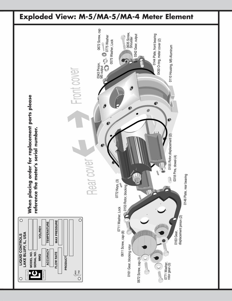
Exploded View: M-5/MA-5/MA-4 Meter Element
0318
Pin
s, d
owel
-(4)
0155
Rot
or,d
ispl
acem
ent (
2)
0153
Rot
or, b
lock
ing
0575
Was
her,
Lock
0342
Gea
r, ou
tput
0635
Scr
ew,
Shou
lder
0110
Hou
sing
, M5-
Alum
inum
0343
Pin
ion,
M
5 ou
tput
0146
Pla
te, r
ear b
earin
g
0430
O-ri
ng, m
eter
cov
er (2
)
0161
Gea
r, bl
ocki
ng ro
tor 01
63 G
ear,
disp
lace
men
t pin
ion
(2)
0144
Pla
te, f
ront
bea
ring
0772
Key
s, (3
)
0672
Scr
ew, c
ap-(3
)
0771
Was
her,
roto
r gea
r-(3)
0611
Scr
ew, c
ap-(8
)
Front c
over
Rear
cover
0775
Was
her
0672
Scr
ew, c
ap
0711
Was
her,
Lock
®
When
pla
cing o
rder
for
repla
cem
ent
part
s ple
ase
refe
rence
the
met
er's
ser
ial num
ber
.
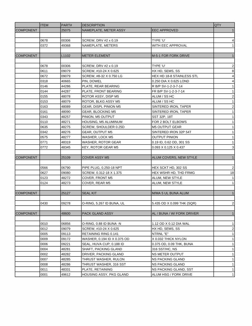
ITEM PART# DESCRIPTION QTY
COMPONENT 25075 NAMEPLATE, METER ASSY EEC APPROVED 1
0678 00306 SCREW, DRV #2 x 0.19 TYPE 'U' 4
0372 49368 NAMEPLATE, METERS WITH EEC APPROVAL 1
COMPONENT L1102 METER ELEMENT M-5-1 FOR FORK DRIVE 1
0678 00306 SCREW, DRV #2 x 0.19 TYPE 'U' 2
0611 09079 SCREW, #10-24 X 0.625 HX HD, SEMS, SS 8
0672 09079 SCREW, #8-32 X 0.750 LG HEX HD 18-8 STAINLESS STL 4
0318 40665 PIN, DOWEL 0.250 DIA X 0.625 LOND 4
0146 44286 PLATE, REAR BEARING R B/P SV-1-2-3-7-14 1
0144 44287 PLATE, FRONT BEARING FR B/P SV-1-2-3-7-14 1
0155 48078 ROTOR ASSY, DISP M5 ALUM / SS HC 2
0153 48079 ROTOR, BLKG ASSY M5 ALUM / SS HC 1
0163 48089 GEAR, DISPL PINION M5 SINTERED IRON, TAPER 2
0161 48090 GEAR, BLOCKING M5 SINTERED IRON, TAPER 1
0343 48257 PINION, M5 OUTPUT SST 32P, 18T 1
0110 48271 HOUSING, M5 ALUMINUM FOR 2 BOLT ELBOWS 1
0635 48275 SCREW, SHOULDER 0.25D M5 OUTPUT GEAR 1
0342 48276 GEAR, OUTPUT M5 SINTERED IRON 32P 54T 1
0575 48277 WASHER, LOCK M5 OUTPUT PINION 1
0771 48319 WASHER, ROTOR GEAR 0.19 ID, 0.62 OD, 301 SS 1
0772 48345 KEY, ROTOR GEAR M5 0.093 X 0.125 X 0.437 3
COMPONENT 25109 COVER ASSY M5 ALUM COVERS, NEW STYLE 1
0566 06790 PIPE PLUG, 0.250-18 NPT HEX SCKT HD, 302 SS 2
0627 09080 SCREW, 0.312-18 X 1.375 HEX WSHR HD, THD FRMG 18
0123 48272 COVER, FRONT M5 ALUM, NEW STYLE 1
0124 48273 COVER, REAR M5 ALUM, NEW STYLE 1
COMPONENT 25127 SEAL KIT M/MA 5 UL BUNA ALUM 1
0430 09278 O-RING, 5.267 ID BUNA, UL 5.435 OD X 0.099 THK (SQR) 2
COMPONENT 48600 PACK GLAND ASSY AL / BUNA / W/ FORK DRIVER 1
0010 06856 O-RING, 0.88 ID BUNA -N 1.12 OD X 0.12 DIA WAL 1
0012 09079 SCREW, #10-24 X 0.625 HX HD, SEMS, SS 2
0005 09113 RETAINING RING 0.141 NTRNL "E" 1
0009 09172 WASHER, 0.194 ID X 0.375 OD X 0.032 THICK NYLON 1
0006 09221 SEAL, HUVA CUP; 0.188 ID 0.375 OD, 0.09 THK, BUNA 1
0004 48281 SHAFT, PACKING GLAND 316 SST/HC, NS 1
0002 48282 DRIVER, PACKING GLAND NS METER OUTPUT 1
0007 48285 THRUST WASHER, RULON NS PACKING GLAND 1
0008 48286 THRUST WASHER, 316 SST NS PACKING GLAND 1
0011 48331 PLATE, RETAINING NS PACKING GLAND, SST 1
0001 49612 HOUSING ASSY, PKG GLAND ALUM HSG / FORK DRIVE 1
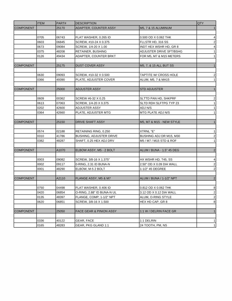
ITEM PART# DESCRIPTION QTY
COMPONENT 25170 ADAPTER, COUNTER ASSY M5, 7 & 15 ALUMINUM 1
0705 06743 FLAT WASHER, 0.265 ID 0.500 OD X 0.062 THK 4
0603 06845 SCREW, #10-24 X 0.375 FLLSTR HD, 316 SS 2
0673 09084 SCREW, 1/4-20 X 1.00 INDT HEX WSHR HD, GR 8 4
0375 48208 RETAINER, BUSHING ADJUSTER DRIVE SFT/BSHG 1
0126 49434 ADAPTER, COUNTER BRKT FOR M5, M7 & M15 METERS 1
COMPONENT 25175 DUST COVER ASSY M5, 7, & 15 ALL BUT SS 1
0630 09093 SCREW, #10-32 X 0.500 TAPTITE W/ CROSS HOLE 2
0366 49390 PLATE, ADJUSTER COVER ALUM, M5, 7 & MA15 1
COMPONENT 25000 ADJUSTER ASSY STD ADJUSTER 1
0609 00362 SCREW #6-32 X 0.25 SLTTD PAN HD, SHKPRF 2
0613 07063 SCREW, 1/4-20 X 0.375 SLTD RDH SLFTPG TYP 23 1
0202 42600 ADJUSTER ASSY ADJ N/S 1
0364 42660 PLATE, ADJUSTER MTG MTG PLATE ADJ N/S 1
COMPONENT 25150 DRIVE SHAFT ASSY M5, M7 & M15 - NEW STYLE 1
0574 02188 RETAINING RING, 0.250 XTRNL "E" 1
0310 41786 BUSHING, ADJUSTER DRIVE BUSHING ADJ DR M15, M30 2
0382 48287 SHAFT, 0.25 HEX ADJ DRV M5 / M7 / M15 STD & ROF 1
COMPONENT A1070 ELBOW ASSY, M5 - 2 BOLT ALUM / BUNA - 1.5" 45 DEG 2
0003 09082 SCREW, 3/8-16 X 1.375" HX WSHR HD, T45, SS 4
0002 09117 0-RING, 2.31 ID BUNA-N 2.50" OD X 0.09 DIA WALL 2
0001 48290 ELBOW, M-5 2 BOLT 1-1/2" 45 DEGREE 2
COMPONENT A2110 FLANGE ASSY, M5 & M7 ALUM / BUNA / 1-1/2" NPT 2
0750 04498 FLAT WASHER, 0.406 ID 0.812 OD X 0.062 THK 8
0420 06854 O-RING, 2.88" ID BUNA-N UL 3.12 OD X 0.12 DIA WALL 2
0135 48397 FLANGE, COMP; 1-1/2" NPT ALUM, O-RING STYLE 2
0620 06851 SCREW, 3/8-16 X 1.500 HEX HD CAP, GR 8 8
COMPONENT 25050 FACE GEAR & PINION ASSY 1:1 W / DELRIN FACE GR 1
0336 40122 GEAR, FACE 1:1 DELRIN 1
0165 48283 GEAR, PKG GLAND 1:1 24 TOOTH, PM, NS 1

����������
���� ���������������������������������������� �������!��"������!"��
� ##��������������$����%��&����������! ��% &���% �'!(!$!
��������������������� ������� ����� ������
��������������������� ��!"���� #�$�����!% &��&�"'&(�)�#������������#����*�
�+,�"�
���������������
����� ������� �� ��������������������������������������������������������� � !"�� !#� �� �� �� ����$� ������������������%���&��� ''�������(�)�������������������������*��������������������������������������+*���������������(�,����������������������������������������*�$���� �� �����������������������������(
������ ������������������"!-�!�����"!-� ���������$�����������������+�$���������(�)��������������������������������!. � �����������������������������/��������)$���!+�������0������1�)$��� +2������*1)$���� 3� ��� 3�+%�����1� ���)$���� 4� ��� 45+6��������(�)��� ����7���������������������������*�����/,�������������������/�������)$���� 3� ��� 3�+%�����1� )$���� 4� ��� 45+6��������1� )$���� -� ��-0+����������1�)$���8���1�91��1�:�2#�/����������*�������'1�2 ���!1��������1�91��1�:�2����)$���;��/1�,1�:��#+2���+'�������*�������''12 ���!1��������/1�,1�:��(�)���������''1��������,�:���2����<�����������������������������*��������������������� �� ��������*����������� �������������������&���������������(������������������������ �������*�������������*����������������.�������*������ ��(�6����������=����������������������������������������� �� �1���������������"( >"+ ��?@,+ 9������������1�"(3�������*����������(
����������������������������������������� ��� !��"������#�$%#���
)�������� ���������$���� ������������!.4�� �����1� �����1����2'@���������%�*������,�����4#(
� �����&�$�#�������#�$%#���
)���������������������*����$���������������������������$������������������������������ ����("- ����(";3����������������7���(�%�*������,�����3������������� ��������� ���� ����� ������� �����
�#������!��#$����!����'����� ��������� $�����
����#�$%#������'� ($�%#����)�*
)���=�������������������������/��������)$���� 1313�141����45(
��$�������������!.4���������������������������$��� ����=����
���(�)���=������������ ������!. ��������������1������������������������������������������������=��������������,����>#(
� ��� �$+������%#���,�#��-�,./��/0
?��� ���� 7�� ��$� *��� �������� ���� 2'@� �������(� )��� 2'@� ������������7����� ������ ���������������������������2'@�)$��43->"����������������,�����-#(
��1��6��������������������A��1��������������������������������������+�������$(� �& ��1��� �23��� #3�� ��������� ��� �� ����+�4��5� #3����#������#$���6��%��6���#3��%���5�73�#3��������������'������+5������$��5���
7��+3#5�"$�#��*��#���"���"$"�6��%��#������%�"�������$���"�+��#��"�%���#��
�'�#3����������-�&���"$"���#$���6��%��6���1��%���#�$%#�����������$�%��5����
0��$�%���6������%���#�$%#���-
���1881������7����������*������������������������1���� ��1�����������(�����7*�����*��������*��� ����������*��B���$(
% ����"-��� ��� ��.�/��01����.�� ����2����3�1��4�5�����&�5��4����.�5����2����3�10���.!6���������7��3 �� 5��5���3 0���8�! ������� �.� �5�� � 1�����������0������ �������
!��)81�,���8�9����: ���;�1��<�8:
�19��������������#�6��������*�������5������#����#����������������=��������
73���� �+��#���� #�"����#$��� �6� 3�4����$�� �#"���3���� ��� ����� #3���
��>���-����������$����6����#��"������%�����73�����%�����?@A�������������$���5���
��#����#�������3�4����$���#"���3����73�����+��#����#�"����#$�����������#3��
�����-�������"����#�=��#������6��������%�-
@�)/���)��������������� �����������+������������������*����������������������������������� ������������������$������������������������������������ ��������������(�)������������������������� ������1���=����������1������� ��������������������������������������1����(�)����B���*�������������������*���������$�����������������7������������*.����+�������*������������)$����8�:�;#(
9 $&���-&�5���� ��.��������04��4����5������!��������
����������1�����!�����2��1���.����4� ���4��4�0���.��������0��� ���� �� �.� 4��4� �� �5������ �� 5����2��� 9���� 5����0� ���30�5��0��8�����4� � ��0���������� �9���������++!��+,!��0��+:1������������
��"����#$���8�"�#�#����,���������� �� ��������������������1���*�����������(�)���������������������������1���$������������������������������������*���*������� ������ ��� ;"��(� ����7� �������� ������ ���*�� ��� ����� ����� ���������� ��� �������� ������� ������ �����������(� ���� �� ������������������������������*����������*���������������(@�)/�� � ,��� ������ ��� ��1� ��*��� ��� ���� �� �����1� �� ���� ���� *��������������������*������$�����(
&��5�������#��������������������+,�"�������0�1����������4������0����,!��,!;�,!,+��!��,,�,%����
%��������8
9�����8���2��9���
���1�<
9�����1����������
��<����� �2����&��5�
)!���*!���!���+���!�
�� ����,��-���-��(���(���(.��+�(/ � � ���0�!��.1
)!���*!���!���+���!�
�,���2��-,��-���((��(2��('��+�(2 � �����0)��.1
��!)�� ���-��(���+�(. � �����0��.1
��!)�2��-��('��+�(2 � �����0��.1
�C����������������������+4"�,��+4"���#(
���#�����+)�������������������������*�����������$��������������$������(&��� ��1� *��� ������� �*�� ��� ���*������1� ���� ������� ������� ��������� �������$��������������������������������$��*�*������������������������������������������+�������$�����(
2����+6�������������$������������������������@������/�������������(����������������������������������������� ���������������������������� ����� ��� ��������� $������ ������� ��� �� !. ��������������(�)�*�����������1��������������$������������3-"�(�,������������������������������*�������1�����������*������������������ ���*���������������� �����A��������������(
1���#������2����+����#�$%#�����!����#������!��#$����� ��� !��"�����������7�#3��=0��������#��"�����
,��� �������� ������������ ������ ������� �������� ����D! +!���6�����������������������������;"�������������(�)��B��������������7����������
���� ���������������������������������������� ������!��"������!"��
����� ����� �������!3)*���
!"�E� �+����F!1"�E�!1 �@�G(�������������������� ����������������*��������1�������D!"+3 ������������(�)��B�������������������!>�+ "+����F!18�+� 13�@�G(����������������������������1��������7����������������������������������7���������������������������������(�)��B���������������!>�+� "�+����F!18�+� 13�@�G(�������>.3 ������7�$������(� ($�%#����)�*
)���=����������������������������������������������������$�������� ����������������������������!. ��������������(������D! +!���6�����������������������$���������������������(�6������=�������������*���������������������;"��������������*����������(�,����������� �������!">�������������������>"�����������! >���������������� �>"���(��*���� ���������� ���7��1� �������� �� ��� ���7��1� �� ��1� ��� ������()������������� ��$������������������(
� ��� �$+������%#���,�#��-,./� �/0
!( )��� ���+*����� ������� �� ��� ���� ���� 2'@� �������� ������������������2'@��������������7�(
( %��� ��������������*����������������(�?������������������ ��1���$�����������7�*�������������� ��(
3( ?���D! +!���6������������������������������;"��������������*���������(�������������������7������������$�!.4�����������������7����������(�)��������*����+������� ���������������������*�������� ���7��� �������(� C������ ������ �*� ���+��� ���� ��� ��� �������������$� !.4�( � )�� �*� ���� ���� �*� ���� ���������� �� ������������(
4( )���������� �������� �������1� ����� ���7��1�������1� ��� ��������� ��(
@�)/������������� �����$�������������;"����������*��������������*��������������������*����������$(>( ����7�2'@��������������������7�*����������������7��(�)�����7�
�������������7�����������������7���������������7������(���������������7�������������� �����������������������(
-( 0����������������7���������������������������������(�)��B�����������������>�E�!�+����F"1-�E�!1!�@�G(
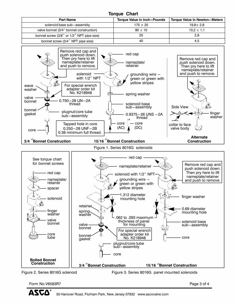
@�)/����������������������#������������������2�#������������������**�����$(�)���� ����*�������������������1�����$�����������$��������������������������������������������������������������+�������$1���=��������������(������������(
���#����#�����6�������������������$������������������������������(�)��������������������$�������*� ������ *�������� ����������*� ���� ������(� �)���3.4�� ���������������,�����!#���������������������*������������������������������������������������(
���#����#�����6� �����&�$�#�����������������,�����3#2�����������������*������������������������ ������������ �������������
/=0��������)����#�����#�$%#���!( '���������������� ����������������#��!(3! �������������������
��������������( ( )���������������������� ���������.�������������+�������$(3( '������������.����� ����� ���+�������$� �������� ������� ���������
����(�)�����������������1���������.�����������������(
�>=����������)����#�����#�$%#���� !( '���������������������+�������$���������"(-;�������������������
��������������( ( 0����� ����� ������� �� �������� ���� �*� ����� � ��� ������� ����
���+�������$������������(
�����������"����#$���������� �������� ���� ������� *��� �������� ���$� ��� ��(�6��� ����������������A���*��������������1�����������������������������������������$�������$�*���������(�)���������*���������������������(
&1���1��
% ����"-&�5��4����.�5����2����3�10���.!���������7��3��5��5���30���8�!�����11��� ��� ��5�=��!0�5�������/��������0�5��������0(��4��4�!��04���1���0�����1�����2�1������4� ��8�
�������+������������������������ �� �����������������������������$(��)����������������������� ��$���������������������� ���������(�'������1�*����� ������������������������������1��������� �� ���������1������ �� ���� ��� ���7���� ���� ������ ����� ������ �� ��B����(���������������*������������������� �� �(
�����#����&���#����%�� H��������������*������������������������������������ �� �����*���
*�����������*�����������������������(� 6�������� ��1������������������������ �� �����������������������������
���������������������������������������(� 2������������������������ ���������1����������������*
������ �� �� ������ *��� ������� ��� ������ �� ����� �� ����������()��������$���������������(�%��������$����������������������(
��$�����6��"�����������#���� !�$�#'����#�������%$�#�� �����7����������������$������$�����A�����
������(�������������������*����������������������������(��������*�����������������������*������������$(�����7�*�����������������*����1���+�������� ��� �������� ������1� ���7�� ����� ����� ��� ������������(
� )$���� $#����������������7�*������+��������������(�%�������*�������$(�����7� �����$� ������I� ���������� ���� �������� ����*������������.������� ��� ���7��� �� ���� ������(� ����7� ������������������������7��������������������=�����(
� 8�7����#�+��������7� ������������������������������(�J������������������������>K��*������� ������(
��������������%�"��#!( �������������������������������������1����������1����������
���(@�)/���$�������������������������������������������������������������������������( ( 2�����������������������������*�����������*�������
� ����������%��7����"�����
%��� �� ������� �������1� ������� �����1� ����������1� �������������7����������������$�����$#(
@�)/�� �,����������������1��������7����������������������������������7���� ��������������������(
� ($�%#����)�*
%��� ��������������7�������������������>.3 ������7�$������#�*����������*�=��������(�2�������=���������*����������(
� ��� �$+������%#��
%��� ��������������*����2'@�������������(�2�������2'@�������������*�����������(�%��� �����7�������������������>.3 ������7�$�����#1�2'@���������������1�������7���*����������(
3( �����**���������*���������*����������������+�������$(4( 0����������������(�)������������������������ ��1������������
�������� �����������������������������.������(�0�$����������$��� ����� ��� ���� �(� � )��� ���� �� ������� *���� ������� �������+�������$(
>( %����������������������� ����*������������*����������������
�������"��'�����������"��'��6����������!( %��� ��������1��������� ������������ �( ( %��� �� *���� ������� ��� ����� ������� � *���� ������� ����
���+�������$(3( ?���������������������+�������$(
@�)/�� � ����� ������� ����������� �� �� �� ������.����� �������+�������$1� ����� ���7��� ��� ����� � ������ �*� ���� ������� �������+�������$(�)������ ���������������������������������������������%������H�(� ,��������� �������� ��$1� �����������6�����H�@�(H !�;4�(
4( )�����������������������*����������������������(>( '*� ���� ������� ��������*� �� �� �1� ��*����������� �� �� �����������
�����������������*���*����������������$(-( %����������������������� ���� *��� ���*������������������*
�����(
��������!�&1���!��1����8����
�
6������������������*����������������������������J�� ��1������������������������������������(����������*$� ����������*��B���$(
���� ���������������������������������������� ������!��"������!"��
�����������������!3)*���
&��>��9.���
�������� &��>����������� .�����0� &��>�����������=����������
���� �%��4�����546�����4�� ���7� ���*7� �*
������4� �&�0�8��4� �&�"� �&�5"&%� 1 ���7��� ��� �7����
4� �&��"����0�8*������8 ����2�9%9���%:�1 �*
4� �&��"����0�8����2�9%9���%:�1 � �
���9��&�8
����
�����
4� �& 9�5� 5&8"����&54��546�����4��
"���0$.1 0/.1
���� �%��4����546�����4��
�!���6 )�'�(�6 $&�����
"���
����"�9
2�99��������% �"���
�! �6 *�'��6 ,�!�*��% %�5���5���&�����!
�����9�"%������ "����9&����������%&��!�- �*�*
�(?@�����9������ ����� ,�(,�@�����9������ �����
�!��6 *�'�6 $&�����
"���
2�� �9��������&���%�& ���9��&�8��&�% ��
�����&
4� �&
������
��������9������ ����
��&�% ��
�����������"�9�� �95������� �%����� !
2�� �9��������&���%�& ���9��&�8��&�% ��
�����������"�9�� �95������� �%����� !
� ��95���&��������!
� ��95���&��������!
�% ���������
�9�% ��������
���� �%�����������%&���8 ����2
���5 �% ���%���6���� �������� ��%&���������&�%9��
"������&����"�������4���
(%���3%��
�%�5����!�(��%���*��);������ �%��
���9��&�8��&�% ��
����"�9
���� �%��4����546�����4��
"���
��&�% ���!)���%���&����5 &% ������
!�) �&��!������<%�5�&�%"� �������9� ���
������5 &% �
9�5� 5&8"����&54��546�����4��
"���
�!�� ��%���&����5 &% ������
�����9�"%������ "����9&����������%&��!�- �*�*
�(?@�����9������ ���� ,�(,�@�����9������ �����
���� �%���%&���8 ����2
�9�% �
�����
4� �&�����&
4� �&
������
����"�9
���9��&�8��&�% ��
�9�"��
�% ���������
�����4� �&
"���&54�
���� �%�
�
2�� �9��������&���%�& ���9��&�8��&�% ��
�����������"�9�� �95������� �%����� !
@����0@�����9������ ����
(���&��=5��"���&������4� �&��"����
� ��95���&��������!
�% ����������
���5 �% ���%���6���� �������� ��%&���������&�%9��
�%�5��� !�(��%���*��);����� �%���������������������������������%�5����!�(��%���*��);��9� �����5 &������� �%���
���� ���������������������������������������� ������!��"������!"��
���������� �������!3)*���
&��>��9.���
�������� &��>����������� .�����0� &��>�����������=����������
&���% ���4��"���"���� ���7� ����7���
��"��&�������"��� ��6� � ����6� ��
"� &����"��� �7�� ��)�7�����
�"����&���% �����9&��
�����&
/>��&���% �����9&��
��"��&�������"���
��"��&��������5 �% ���"���
?9� 6������(��� �%�?9� 6������(��� �%� ?9� 6������(��� �%��%&��("����2���% ���!(�"��&�������"����%�5�����������5 �% �!
�%&��/>��2���% ���!
&�99�����������@��6� ����5 �% ���"���0 �&�% "�5���1
(���&��=5��"���&
�4���
&���% ��4��"��"���
�%&���8��(9����2���% ���
08� ����<�������� "�1 08� ����<�������� "�1
> �%"�&���9��&���599�%��% �2���% �&%� �#��5��
-%&���!�- )��
�%�5���!�?9� 6���������� �%��
"������"���
"����������&
"����
A5 "&%� �4�<������&
A5 "&%� �4�<��%&�
� �����5 �% ��&���% ����"��&�������"���
�"����&���% ���4��"�0���� �&�1
���5 �% ���"���� ��"59�������
�5 "&%� �,�<�(��� �%�
��&�B
�5 "&%� �4�<��%&���"����&���% ������� !�C%&���"����&���% ��4��"���������������% % ��9��&�"��9�%���&���A5 "&%� �4�<�����9����&���% ���"� �&�5"&%� !
(���&��=5��"���&
�4������("����2���% ���
08� ����<�������� "�1
�8 ��"� �5%&�"� �"&%�
�%&���8��(9����2���% ���
�%�5���!��5 "&%� �4�<�0�9&%� ������&5��1
��� �� 5&
��� �������&
��������"��&�������"���
�����&
/>��&���% ��
"� �"&��
"� �"&���"����
"� &����"���
���9&��
�����&
0���� �&���1
/>��"� �"&��
&���% ���4��"�
0���� �&�� 1
> �%"�&���&��&�&�����9��&������% "�5���?9� 6������(��� �%�
% �/>��9�5��"� �"&���-%&���!�- �)��
(���&��=5��"���&
�4���
�%&��/>��2���% ����5��.� �"&��
��&��B
�!��.� �"&���"���������4�
9��%&%� ����� �������&�� �&�9��%&%� ����"�4���� &��!
!��������&������% ���� �/>�"� �"&�������9��9�����"&�%"���"� �"&%� �!
��&�&���% �����% "���� &������
08� ����<�������� "�1
�%�5���)!�/>��9�5��"� �"&����%&���!�- �)���0�9&%� ������&5��1
����������
���� ���������������������������������������� �������!��"������!"��
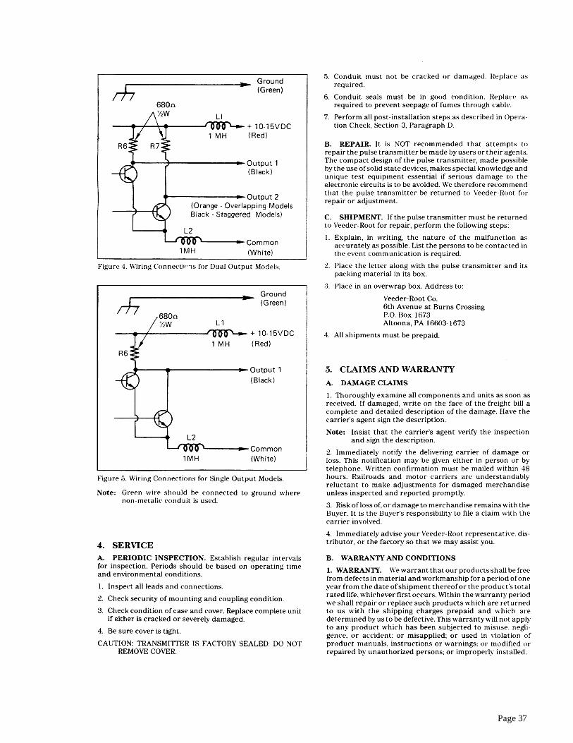
�
#����$��%����������!&���'(
��������������������� ������� ����� ������
������������
������� ����!"�!# �#"��� �$�#!��#�$��!��� %�&'�#���!!�(!#��$#"��� �#�)*�����!�����(�
&�+&,�#�&-��"
%�&&
�������� � � �� � �� �������� ���� �� ����� ��� � ���� ��
����������������� ������ ��������� �������������������� ����
� ����������������� ������������������������ �����
����������������� ��� �� ���� ���� ������ ����� �� � ����� ������� �� �������������� �������� ����������������������� ������������� �������������������������������������������������� ����������������������������� ����������� ��������� �������������� �������������������������������������!���������������������� ����� ��� �!� ����������� ��� �!� ����������"������������ ��������� ������
���� ����
���� ��!����������� ������� ������������ ������������������#��$����������������#���
�"���� �����"���������� �������������������� �����#�����
" �� ����� ����$������ ��� ���%%���� ����������� ��������� ������������������������������������� ������� ���������������&�������������� ����������'����������� ��()����� ������ ��*��������� �������������������� ����� ������������������������������������������ ���������������#�����&����������������� ���������'� ���������� ��()������ ������������� ��*��������� ���������������
"������.��/�0������#1������
���2�2�+������.�� �� 3/����������
4�������1�
(�5 �#�6 7�� .��.� �� �1����� ��� ��� ���8+ 9������1��������.��9���:�0���8������; ������ �� 3/����
��� && ����
+���*� ����� ���� ���� �������� ���� ��� ������)� ��������)� �� ����)���,�����)��������������-�������� ������������ ��� ���������!����������������������������� ����.���� ������������ ���������������������������������,�� �������������� �
'������(���������� �����/��������� ���� �� �������� ���� ����������� ����� ��*���)� �!����� ��*���)��������������� ���������������� ���������������#������)������������ ��� ������������������� �������������� ��
���� ����&���� ����� �����!������� ���������������� ����������������)����������������� �����+���*����� ���������������!������������������������� ����
���������2
�(<$(
(�����2��9:��"��0�=
�������;(����
��=�9�9�9:���� �91�
��=�9�97���; �91�
(�� �����*� �
� ��+��),
�'���+' �),
#) �- �����+(��),
�'���+' �),
(!��� ���.��/�����/)
�� ���+��),
�'���+' �),
#) �-��.���/-����/0
�����+(��),
�'���+' �),
��!
*)�� ������- ������
����+ �),
����+(�),
��!(
*)
�� ����-�.���.���/)�/�����/-
����������+��),
����+(�),
�����������&������ �������������������������������� �������������������������������0������)������������� �������������������)������� ��������� �������������������� ����������������������������������� ��������������������������� ��������������� ��������������������� �������
������+������������������� �������������������*���������� ����������1�� ���������������������� ������� ����������������� ���.����� �������� ��� �������)� ���� ��������� ���� ������ ���� �� ��� ���� ��������������� �������� ����1�������������������������� ����������������� ������� ��������2���� ����������� ���� ����)� ��� ���� ���� �� ��� ���� ����������� ������3������������������ ��������� ��������������������� ������������� ����������������������
(�5 �#�6 �1���� ��4��������;.��.�+������������������0����������:��0���4����.� ���.��.�;���4��������;��� �������4�.��.���1����:���(����1����;� ���8;�1��;��2�����.� � ��;������������(#������%�''+%�'&��;%�'�0������������
" ����� ���
������*6 �1��.��� �4�1����:����8�0;���4+���������>��8��1��1���8;�9�2�+�����00��� ��� ��1�/��+;�1�������?�.��.�+��;.���0���;�����0�����:�0������.� ��2�4�.��.��
-4&�5��.����������������������������������� ���������������� ���������������
���� ���������������������������������������� ������!��"������!"��
����� ����� 123���!4�(��
�� ����1 ��� �������� �������� ������ ��������������� ���&���������������� ���������� �����������������������������������������������������.�������� )���������� ��������������� �����������)�� ��������� ������������)�!����������������� ��*������ ���������������� ������������,�������.������!����������)���� ����� ��������������� ����������������� ��������� ������������� �����+ ������������������ ���������� ������������� ���
��(���(�" ���� ��
� 6������������ �������������������� ��������������������������������������� ���������� ��
� /���������!���������������� ������� ������������������������������ ��������������������������������������)�� �������������������)� ���� �������������� ��� �� ��)� ��� ������ ����������� ����� ��� ���������� �������� ���������������������� ����&�������� ����,���������!������������������� �����������������������������������������1���������� ������������������������������������������������������������ ����������!���������� ���
� 7��������� ��� ���� ������� ���� �������� ����������)� ���������������������� ������� � �� ��������� ���������������!���������������������������� �&������� �� � ���� � �������� � .�� ������������������������)������ ������� ��������� ��*���
� ������������������ ����� ������������������+���*��� �������������/������������� ����������������������������������������� ����
� �)����(�& * ����7�������� ���� �������� ����� ��������.��������������������������)������ ������� ����1�+4�8���� ��6���
+ �(���� ���,�!� 7�������� ���� �������������� �����������������!� ����������
������������������������ �������������������8�������� ����������1+�������������$� ������������7+���������������� ���������9�-/&��� ���������������)� ���� ������$� �����:��-/&��� ��������������)����� ��������
�� 8�������� ��������� ����������������������������������
� ����� �������� ���������������� ������ ����������)��������������������������� ��������������
;� <��������� ��������������������� ��������� ���������&���������� ����� ������ �� ����� ����� ������� ���� �� ������ �������*����� ���1+��������������' ������(������������������ ����������
=� ��� ����� � ������������ '� ������(� ��� ��� ���� ���������� ��������������� ����������0������)������� �������������� ������>"?��������� ����*���������
@� 8������ ������� ������)� �� ��� ������)� ���������� ������)���������������� �)���������*��)����������������� ���'�������������������� ������������������� �(���������������������*���
?� 1 ����������������������� ������� ������������� ��������� �.��������������������������)������ ������� ����1�+4�8���� �6���
-��(���������-
�.������ ������ ��/� ����,�����0������ ��,� / ���. ���.
�� �.� ��� ���,�!� � !� ���� ,� ������ �� ��� �.� �� �.� ��
���,�!� ��� �.� ( �(�� � � '����� 1� ���� ���� �� �� �.� ��
��������������� � �.� �/�� �� �.� ��� �������������� �
�����. �� ,�� ���/�����������2� ��!�/���
(�5 �#�6 �������1��1��.��.��1�������+����������1������11���;����(#��:���;@���$����9�=��;��;��/1�����
+ �(�� ���,�!� 3�����������������*��)�����������������*��)�����������*������
�� ������ ����� ���*��� ����� 742� +48-.-A�� �� ��� ����������������,���� ����������������� ������� ����
�� .���� �����������������*��)����������������� ��)���������������� �)�����������������)��� ����������������������������0���������������������������������� ����&�������,������������������������������������������==�B�@���� ���C?);�B�)>-�D�
;� .�� �������)� ����� ��� �������� ����� ��������� �1�� ������� ���������������������������������� ��������� ������������� ��� ����� ��������� � &��,��� �� ��� ����� ��� >@�B� � ��� ���C�)@�B�)�-�D�
� ����� �������� ���������������� ������ ���������)�������������������������� ��������������=� ���1+�������������� ' ������()� ����� � ����� ������� �������
������ ��� �2������������������������������������)�� �����������������������������������
@� .���� ��� ��������������*��)������������ ������������������������ ��������������������� ������� ����������&��,����� �������������������� �����>@�B��@���� ���CE)��B��)��-�D�
?� .���� ��� ����������������������������������
������*6 �1��.��� �4�1����:����8�0;���4+������� ��>��8 �� 1��1���8 ;�9�2�+ 4� 3 .��.� 0��1��1�� �1������� :�0��� ��������2 �� ���.� �� ����1��0��9��������������;�=���������3�2������/��4����4�?��;���+��� �9:����:��0���;�
>� 8������� ������������������ ������� ����������� ������� ����� 1������������������������ ����)��������������� ��������������
���������������������������������1����� ������������������������ �������������������
��� ���,�!����" �� ����� ���� <��������� ��������������������� ������������ ���������
������� <������������ ���������������������� ����������&����������
����� ��������� ����� ����� ��� ����� � ��������� ����� �������"����������������� ��
;� /� �����"����������������� ���������������*�������������������� �����������������&���������������������� �����������������)� �� ������ ����� ���*��� ���� ����� � ��������� ���������*���
=� �������������������� �������������������������������������
�����=�
� ���,�!����" �� ����� ���� 3��������� ����� ���*��� ����� 742� +48-.-A��
+�������� ��������� ��� ��� �,���� ���� ����������� �� ������������
�� ���1+�������������� ' ������()� ����� � ����� ������� ������������� ��� �2������������������������������������)�� �����������������������������������
;� 0� �������������� ������������������������#���� ���������)����� ������������ ���������������������������������������
=� .��������������"����������������� �������������������*������������������ �������������� �����������������8���������� ���������������"����������������� ������������F� ��*����������
@� .���� � ������������������������������ ���������������������� ������� �� ������� ��� ����� ���� � ��� ��������� ��� �������"����������������� ��
�"���� ������.��� �������.����3�� �����,- ���,�!�����
�� �����������.������� �������� ���������������$'�����1%� ��
������������.������� ������������������������$'�����4%�
?� .���� � ����� � ��������� ������� ���*��� ���� ����� ������������� ���������������� ����������&��,�������� �����������������>@�B��@���� ���CE)��B��)��-�D�
>� 8�� ������ ��������������*��������� ��������������������� ��&��,��� �� ������ ����� ���������� �� ��� >@� B� �@� ��� ���CE)��B��)��-�D�
�� ������������������� �)������������������������������?�
���� ���������������������������������������� ������!��"������!"��
����������123���!4�(��
��A��(4���
"�����9� ��A�������
�� 4�"���;�
��A�������
��/����������
/��� �$��5���
�657�����5���� 8 �� ' 8 '
3� 6����9���%��
5���
���8� ���'�8� �'
:� �%��"��� ��8�� �(���8����
4��������% ��8��� '��8����
�������5����'��" ����
�'���� ������67�&���0��
/��������*������������������*�'G(���������!� ������������������ ������8���� ��6������2����4��������8���� ��6��������1�+4��� ���)����������8���� ��6��������������������������� �������� ������.�������������������*��������������� �)�����������������������������������*�����,�����)���������+��� ���-��������������� �-��������������� ��'�(����������������������������
���������%
5����9������������%
5���������%
�$�9�������9�$ �
������5� �%
���� �$��5���������%
������5���
5� �%��"����+,
���� �$��5���
"�����9�$ �
���� �$��5���
�%�����%�$ ��
+���� �%�,
�����%
�657�����5��
"���������5��
5� �%������%
�%��������%
�%��;�9�"���657�����5��
���� �$��5����657�����5��
"�����9�$ �
"���������5��
�%�����%�$ ��
�9�"��
�� 6����9���%��5���
��"#� ��
/���%��<6�"���%
+���� �%�,
���������%
���5�!#"��� #�
B#" �#��!C
��"#� �� �%��;�9�"���657�����5��
��%�=
>$���� �����"�����9�$ ��$ �"�����$��%�
"������� ��9��%�6���������%�9����"���!
)�9%$����9�"���� ��%��;�9�"���657�����5����6�%�5����"�%��� �%���$ �$�������%�����%�$ ��
��� ��������5���!
"�� ��!����
�$�6����!��/��$���' ����������$%��6%����� �$���#)�"� �%�6"%$� ��$%����������?����-�������5�������� !
5����9������������%
�$�9����������5��
"���������/�0���������(������ ����
1 �$"�%������%��/699�$��1 �#/)@���56$���.$%�
-�$��9��%�$���# �699�$���$ ������$%�
�$�9����������5��
�
�
���� ���������������������������������������� ������!��"������!"��
���������� 123���!4�(��
�$�6��� !�/��$���' ����������$%��6%����� �$���*)�"� �%�6"%$� ��$%����A����-�������5�������� !
5����9������������%
�$�9�����������5��
�$�9�������9�$ �
������5� �%
������5���
5� �%��"����+(,
5����9������������%
���� �$��5���������%
���������%
5���������%
���� �$��5���
���� �$��5���
�%�����%�$ ��
�����%
�657�����5��
"���������5��
5� �%������%
�%��������%
�%��;�9�"���657�����5��
���� �$��5����657�����5��
"���������5��
�%�����%�$ ��
�9�"��
�� 6����9���%��5���
)�9%$����9�"���� ��%��;�9�"��
�$%��"�����9�$ �
�$%��"�����9�$ �
���������%
�657�����5����6�%�5����"�%����� %����6%�$�������%�����%�$ ��
��� ��������5���!
��"#� ��
�%��;�9�"���657�����5��
���5�!#"��� #�
B#" �#��!C
��"#� ��
/���%��<6�"���%
"�� ��!����
1 �$"�%������%��/699�$��1 �#/)@���56$���.$%�
-�$��9��%�$���# �699�$���$ ������$%�
�
�
Page 33

Page 34

Page 35
Page 36
Page 37
Page 38
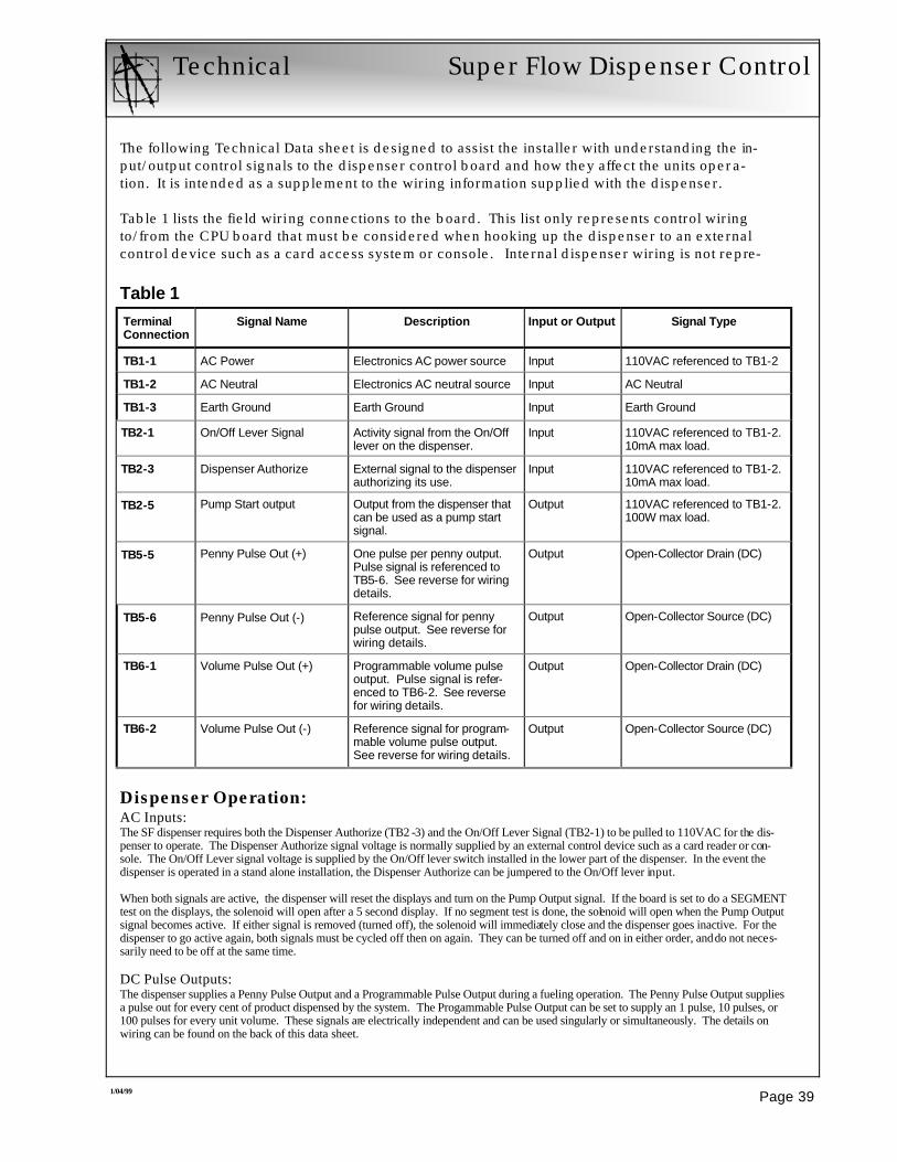
Dispenser Operation: AC Inputs: The SF dispenser requires both the Dispenser Authorize (TB2 -3) and the On/Off Lever Signal (TB2-1) to be pulled to 110VAC for the dis-penser to operate. The Dispenser Authorize signal voltage is normally supplied by an external control device such as a card reader or con-sole. The On/Off Lever signal voltage is supplied by the On/Off lever switch installed in the lower part of the dispenser. In the event the dispenser is operated in a stand alone installation, the Dispenser Authorize can be jumpered to the On/Off lever input. When both signals are active, the dispenser will reset the displays and turn on the Pump Output signal. If the board is set to do a SEGMENT test on the displays, the solenoid will open after a 5 second display. If no segment test is done, the solenoid will open when the Pump Output signal becomes active. If either signal is removed (turned off), the solenoid will immediately close and the dispenser goes inactive. For the dispenser to go active again, both signals must be cycled off then on again. They can be turned off and on in either order, and do not neces-sarily need to be off at the same time. DC Pulse Outputs: The dispenser supplies a Penny Pulse Output and a Programmable Pulse Output during a fueling operation. The Penny Pulse Output supplies a pulse out for every cent of product dispensed by the system. The Progammable Pulse Output can be set to supply an 1 pulse, 10 pulses, or 100 pulses for every unit volume. These signals are electrically independent and can be used singularly or simultaneously. The details on wiring can be found on the back of this data sheet.
Technical Super Flow Dispenser Control
The following Technical Data sheet is designed to assist the installer with understanding the in-put/output control signals to the dispenser control board and how they affect the units opera-tion. It is intended as a supplement to the wiring information supplied with the dispenser. Table 1 lists the field wiring connections to the board. This list only represents control wiring to/from the CPU board that must be considered when hooking up the dispenser to an external control device such as a card access system or console. Internal dispenser wiring is not repre-
Page 39 1/04/99
Terminal Connection
Signal Name Description Input or Output Signal Type
TB1-1 AC Power Electronics AC power source Input 110VAC referenced to TB1-2
TB1-2 AC Neutral Electronics AC neutral source Input AC Neutral
TB1-3 Earth Ground Earth Ground Input Earth Ground
TB2-1 On/Off Lever Signal Activity signal from the On/Off lever on the dispenser.
Input 110VAC referenced to TB1-2. 10mA max load.
TB2-3 Dispenser Authorize External signal to the dispenser authorizing its use.
Input 110VAC referenced to TB1-2. 10mA max load.
TB2-5 Pump Start output Output from the dispenser that can be used as a pump start signal.
Output 110VAC referenced to TB1-2. 100W max load.
TB5-5 Penny Pulse Out (+) One pulse per penny output. Pulse signal is referenced to TB5-6. See reverse for wiring details.
Output Open-Collector Drain (DC)
TB5-6 Penny Pulse Out (-) Reference signal for penny pulse output. See reverse for wiring details.
Output Open-Collector Source (DC)
TB6-1 Volume Pulse Out (+) Programmable volume pulse output. Pulse signal is refer-enced to TB6-2. See reverse for wiring details.
Output Open-Collector Drain (DC)
TB6-2 Volume Pulse Out (-) Reference signal for program-mable volume pulse output. See reverse for wiring details.
Output Open-Collector Source (DC)
Table 1
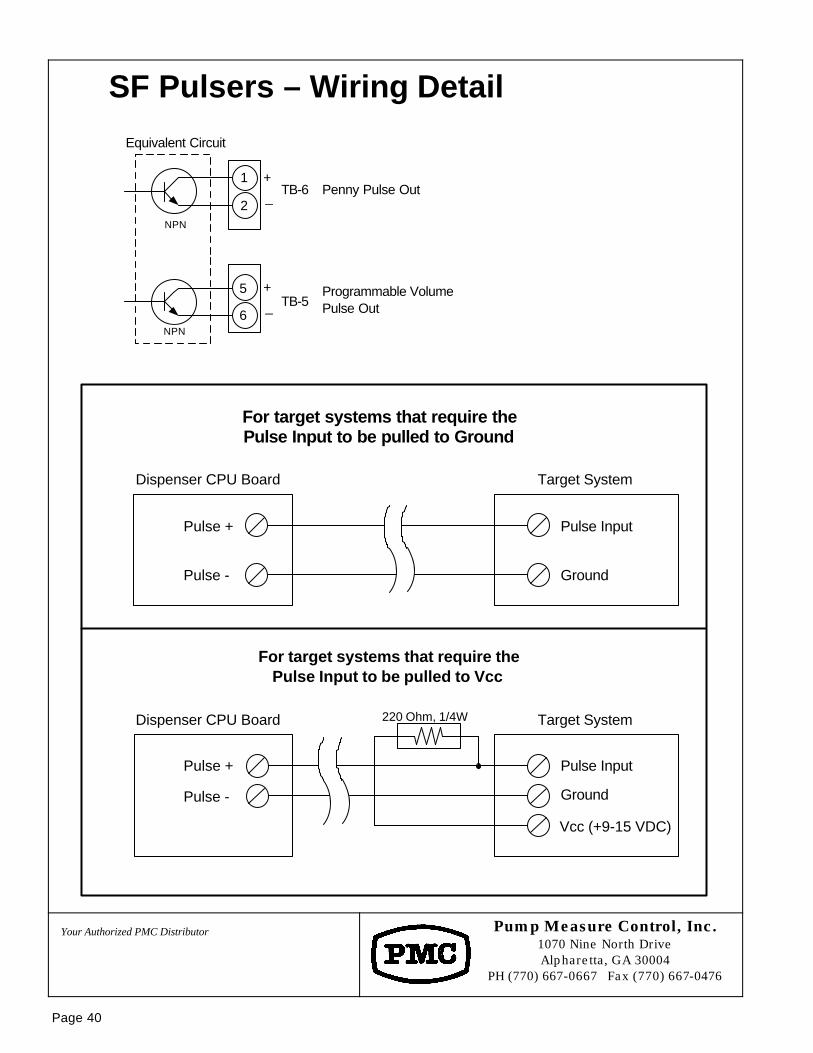
SF Pulsers – Wiring Detail
Pump Measure Control, Inc. 1070 Nine North Drive Alpharetta, GA 30004
PH (770) 667-0667 Fax (770) 667-0476
Your Authorized PMC Distributor
Page 40
1
2
Equivalent Circuit
6
5
+_ TB-6
+_ TB-5
Penny Pulse Out
Programmable Volume Pulse Out
NPN
NPN
220 Ohm, 1/4W
For target systems that require the Pulse Input to be pulled to Ground
Dispenser CPU Board
Pulse +
Pulse -
Target System
Pulse Input
Ground
For target systems that require the Pulse Input to be pulled to Vcc
Dispenser CPU Board
Pulse +
Pulse -
Pulse Input
Ground
Vcc (+9-15 VDC)
Target System
DRAWING NUMBER:
DATE:
SCALE:
06/21/98Pump Measure Control, Inc.1070 Nine North Drive, Suite 100
Alpharetta, GA 30004
PH. 770-667-0667 FAX 770-667-0476
NTS
DRAWN BY:
PART NO:
GJG
"THIS DRAWING CONTAINS PROPRIETARYINFORMATION AND IS SUBJECT TO
COPYRIGHT OWNERSHIP BY PMC, INC"
TERMINAL DESCRIPTIONS NO. DESCRIPTION
TB1-1 110VAC HOTTB1-2 NEUTRALTB1-3 EARTH GROUNDTB6-1 PROGRAMMABLE PULSE PER UNIT OF VOLUME OUTPUT +TB6-2 PROGRAMMABLE PULSE PER UNIT OF VOLUME OUTPUT -TB5-5 PULSE PER ¢ OUTPUT +TB5-6 PULSE PER ¢ OUTPUT -TB4-1 +12VDCTB4-2 DC GROUNDTB6-4 SIGNALTB2-1 PUMP LEVER ON INPUTTB2-3 PERMISSIVE INPUTTB2-5 PUMP START OUTTB2-7 DISPENSER SOLENOIDTB2-8 DISPENSER SOLENOID
91-98G07.2
DISPENSER JUNCTION BOX
SOLENOIDVALVE
TB1-1TB1-2
TB1-3
TB2-5
TB2-1TB2-3
TB2-8
TB6-1TB6-2
BLACK
RED
YELLOW
BLUE
RED
RED
RED / BLACK
ORANGE/WHT
YELLOW
ORANGE
GREEN
WHITE
BLACK
WHITE / ORANGE
DISPENSERCONTROLLER
BOARDN
OZ
ZL
E H
OO
K S
WIT
CH
SF DISPENSER WIRINGAS SHIPPED FROM FACTORY
TB2-7 RED / YELLOW
TB5-5TB5-6
BLUEWHITE / BLUE
TB6-4
TB4-1TB4-2 WHITE
RED
BLACK
100:1 SOLIDSTATE PULSER
WHITE
RED
BLACK
NOTES: 1. Ellipses represent conduit openings (groupings) within the junction box.2. Tied off blue wire is unused. Extra and/or pull wire.
GREEN
FIELD WIRINGCONDUIT ENTRIES
1
2
3
1213
1415
9
1011
4
5
6
7
8
APPLICABLE TO DISPENSER SERIAL NUMBERS
16
17
19
20
21
22
23
24
25
18
ORANGE
REVISIONSNO. DESCRIPTION DATE
1 REVISED WIRE NUMBERING 1/1/04
2 CONNECTION RED#23 TO OR/WH#6 1/1/04
3 ADDED COMM WIRES 4/16/09
CO
MM
UN
ICA
TIO
NS
DA
UG
HT
ER
BO
AR
D
WHITE/PURPLE
32
PURPLE 30
BROWN
31
OPTIONAL+
-GND
TB1
12000 and HIGHER
SEE APPENDIX 'A'
DRAWING NUMBER:
DATE:
SCALE:
07/12/00Pump Measure Control, Inc.1070 Nine North Drive, Suite 100
Alpharetta, GA 30004
PH. 770-667-0667 FAX 770-667-0476
NTS
DRAWN BY:
PART NO:
GJG
"THIS DRAWING CONTAINS PROPRIETARYINFORMATION AND IS SUBJECT TO
COPYRIGHT OWNERSHIP BY PMC, INC"
REVISIONSNO. DESCRIPTION DATE
1 REVISED WIRING 1/1/04
2 ADDED CALL SIGNAL INTERFACE 1/1/04
3 ADDED COMM WIRING 4/16/09
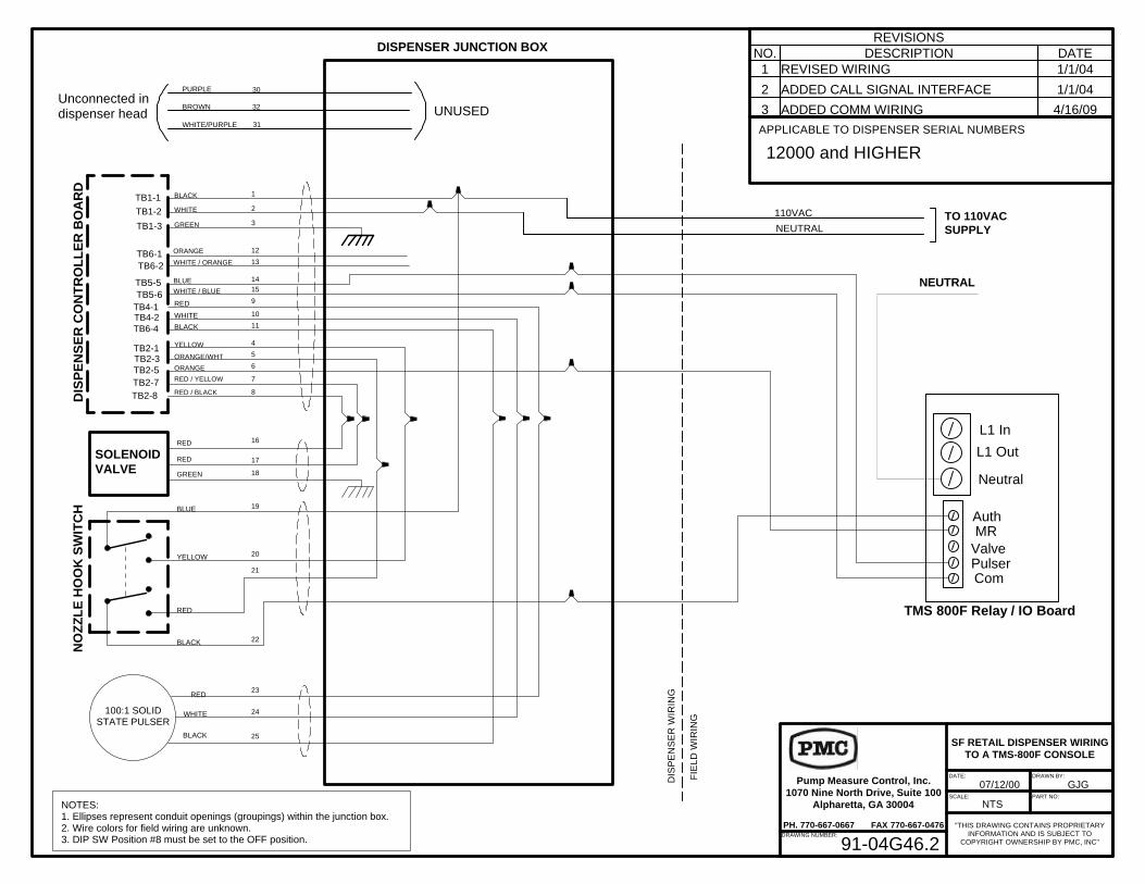
91-04G46.2
DISPENSER JUNCTION BOX
SOLENOIDVALVE
TB1-1TB1-2
TB1-3
TB2-5
TB2-1TB2-3
TB2-8
TB6-1TB6-2
BLACK
RED
YELLOW
BLUE
RED
RED
RED / BLACK
ORANGE/WHT
YELLOW
ORANGE
GREEN
WHITE
BLACK
DIS
PE
NS
ER
CO
NT
RO
LL
ER
BO
AR
DN
OZ
ZL
E H
OO
K S
WIT
CH
SF RETAIL DISPENSER WIRINGTO A TMS-800F CONSOLE
TB2-7 RED / YELLOW
TB5-5TB5-6
TB6-4
TB4-1TB4-2 WHITE
RED
BLACK
100:1 SOLIDSTATE PULSER
WHITE
RED
BLACK
DIS
PE
NS
ER
WIR
ING
FIE
LD W
IRIN
G
TO 110VACSUPPLY
AuthMR
ValvePulserCom
L1 In
L1 Out
Neutral
TMS 800F Relay / IO Board
NOTES: 1. Ellipses represent conduit openings (groupings) within the junction box.2. Wire colors for field wiring are unknown.3. DIP SW Position #8 must be set to the OFF position.
110VAC
NEUTRAL
1
2
3
12
13
1415
9
10
11
4
5
6
7
8
16
17
19
20
21
22
23
24
25
18GREEN
NEUTRAL
WHITE / ORANGE
BLUEWHITE / BLUE
ORANGE
WHITE/PURPLE
32
PURPLE 30
BROWN
31
Unconnected indispenser head UNUSED
APPLICABLE TO DISPENSER SERIAL NUMBERS
12000 and HIGHER
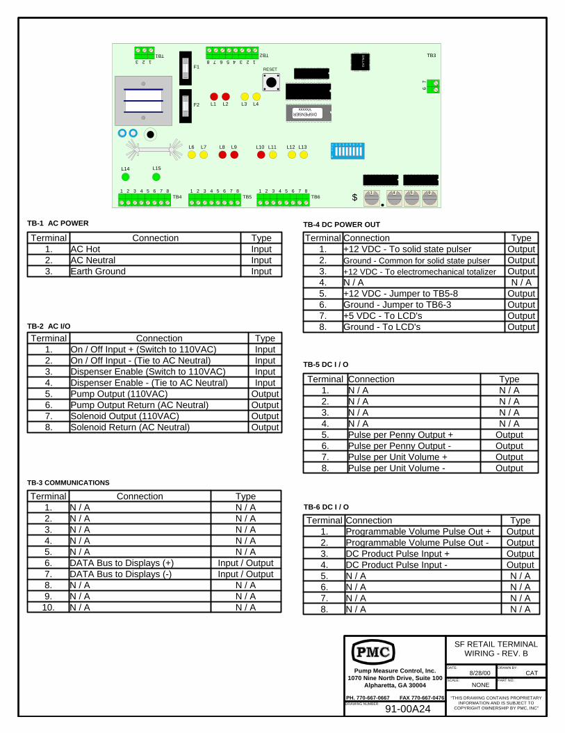
TB-1 AC POWER
TB-2 AC I/O
Terminal Connection Type1. On / Off Input + (Switch to 110VAC) Input2. On / Off Input - (Tie to AC Neutral) Input3. Dispenser Enable (Switch to 110VAC) Input4. Dispenser Enable - (Tie to AC Neutral) Input5. Pump Output (110VAC) Output6. Pump Output Return (AC Neutral) Output7. Solenoid Output (110VAC) Output8. Solenoid Return (AC Neutral) Output
Terminal Connection Type1. AC Hot Input2. AC Neutral Input3. Earth Ground Input
Terminal Connection Type1. N / A N / A2. N / A N / A3. N / A N / A4. N / A N / A5. N / A N / A6. DATA Bus to Displays (+) Input / Output7. DATA Bus to Displays (-) Input / Output8. N / A N / A9. N / A N / A10. N / A N / A
F1
F2
67
TB3
4 5 6 7 81 2 3 51 4 9
$
DISPENSERVxxxxx
RESET
DA
LLAS
L1 L2 L3 L4
L7 L9 L10 L11 L12 L13L6 L8
L14 L15
OFF
1 2 3 4 5 6 7 8
TB44 5 6 7 8
TB51 2 3 4 5 6 7 8
TB61 2 3
45678TB2
123TB1
123
Terminal Connection Type1. +12 VDC - To solid state pulser Output2. Ground - Common for solid state pulser Output3. +12 VDC - To electromechanical totalizer Output4. N / A N / A5. +12 VDC - Jumper to TB5-8 Output6. Ground - Jumper to TB6-3 Output7. +5 VDC - To LCD's Output8. Ground - To LCD's Output
TB-3 COMMUNICATIONS
TB-4 DC POWER OUT
TB-5 DC I / O
Terminal Connection Type1. N / A N / A2. N / A N / A3. N / A N / A4. N / A N / A5. Pulse per Penny Output + Output6. Pulse per Penny Output - Output7. Pulse per Unit Volume + Output8. Pulse per Unit Volume - Output
TB-6 DC I / O
Terminal Connection Type1. Programmable Volume Pulse Out + Output2. Programmable Volume Pulse Out - Output3. DC Product Pulse Input + Output4. DC Product Pulse Input - Output5. N / A N / A6. N / A N / A7. N / A N / A8. N / A N / A
DRAWING NUMBER:
DATE:
SCALE:
8/28/00Pump Measure Control, Inc.1070 Nine North Drive, Suite 100
Alpharetta, GA 30004
PH. 770-667-0667 FAX 770-667-0476
NONE
DRAWN BY:
PART NO:
CAT
"THIS DRAWING CONTAINS PROPRIETARYINFORMATION AND IS SUBJECT TO
COPYRIGHT OWNERSHIP BY PMC, INC"
SF RETAIL TERMINALWIRING - REV. B
91-00A24
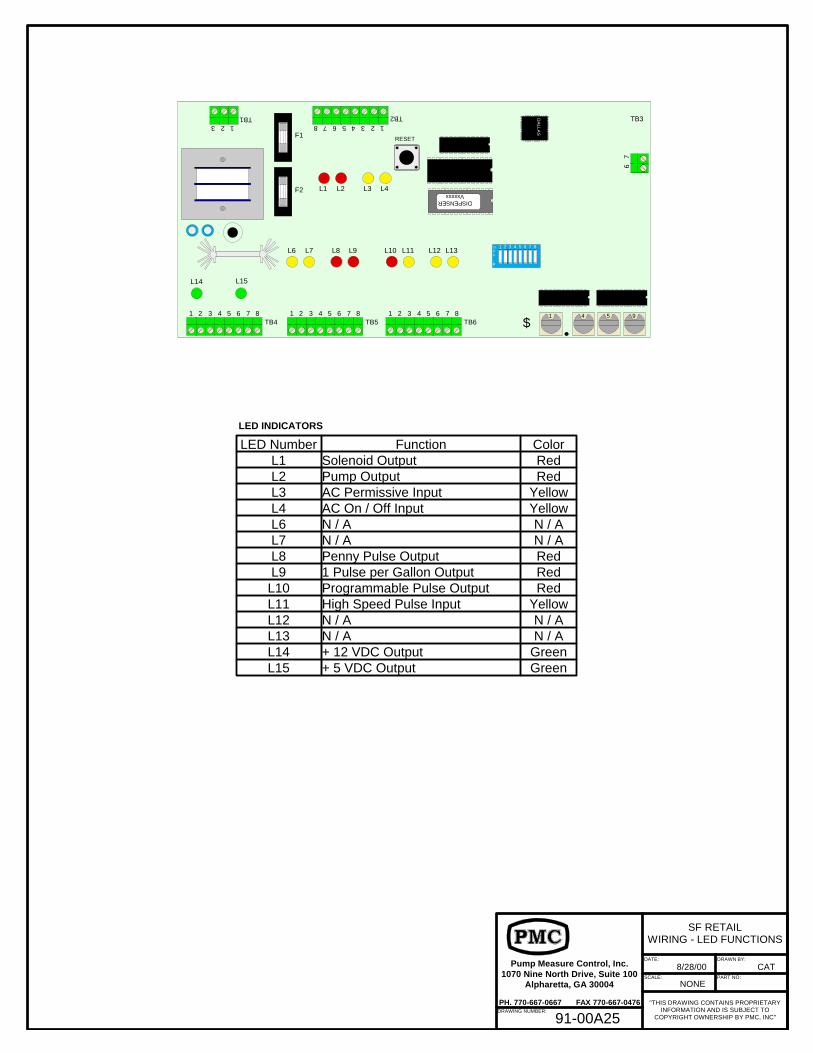
LED Number Function ColorL1 Solenoid Output RedL2 Pump Output RedL3 AC Permissive Input YellowL4 AC On / Off Input YellowL6 N / A N / AL7 N / A N / AL8 Penny Pulse Output RedL9 1 Pulse per Gallon Output RedL10 Programmable Pulse Output RedL11 High Speed Pulse Input YellowL12 N / A N / AL13 N / A N / AL14 + 12 VDC Output GreenL15 + 5 VDC Output Green
LED INDICATORS
F1
F2
67
TB3
4 5 6 7 81 2 3 51 4 9
$
DISPENSERVxxxxx
RESET
DA
LLAS
L1 L2 L3 L4
L7 L9 L10 L11 L12 L13L6 L8
L14 L15
OFF
1 2 3 4 5 6 7 8
TB44 5 6 7 8
TB51 2 3 4 5 6 7 8
TB61 2 3
45678TB2
123TB1
123
DRAWING NUMBER:
DATE:
SCALE:
8/28/00Pump Measure Control, Inc.1070 Nine North Drive, Suite 100
Alpharetta, GA 30004
PH. 770-667-0667 FAX 770-667-0476
NONE
DRAWN BY:
PART NO:
CAT
"THIS DRAWING CONTAINS PROPRIETARYINFORMATION AND IS SUBJECT TO
COPYRIGHT OWNERSHIP BY PMC, INC"
SF RETAILWIRING - LED FUNCTIONS
91-00A25
F1
F2
12
TB3-A
4 5 6 7 81 2 3 51 4 9
$
DISPENSERVxxxxx
RESET
DA
LLAS
L1 L2 L3 L4
L7 L9 L10 L11 L12 L13L6 L8
L14 L15
OFF
1 2 3 4 5 6 7 8
TB44 5 6 7 8
TB51 2 3 4 5 6 7 8
TB61 2 3
45678TB2
123TB1
123
4
TB1123
DA
LLAS
4
TB1123
DA
LLAS
4
TB1123
OFF
1 2 3 4 5 6 7 8D
ALLA
S
4
TB1123
DA
LLAS
4
TB1123
DA
LLAS
4
TB1123
OFF
1 2 3 4 5 6 7 8D
ALLA
S
4
TB1123
OFF
1 2 3 4 5 6 7 8
DOLLAR DISPLAY
VOLUME DISPLAY
PRICE PER GALLON DISPLAY
Binary Switches1-On2-Off3-Off4-Off5-On6-Off7-Off8-Off
Binary Switches1-Off2-Off3-Off4-Off5-On6-Off7-Off8-Off
Binary Switches1-Off2-On3-Off4-Off5-On6-Off7-Off8-Off
4
TB1123
4
TB1123
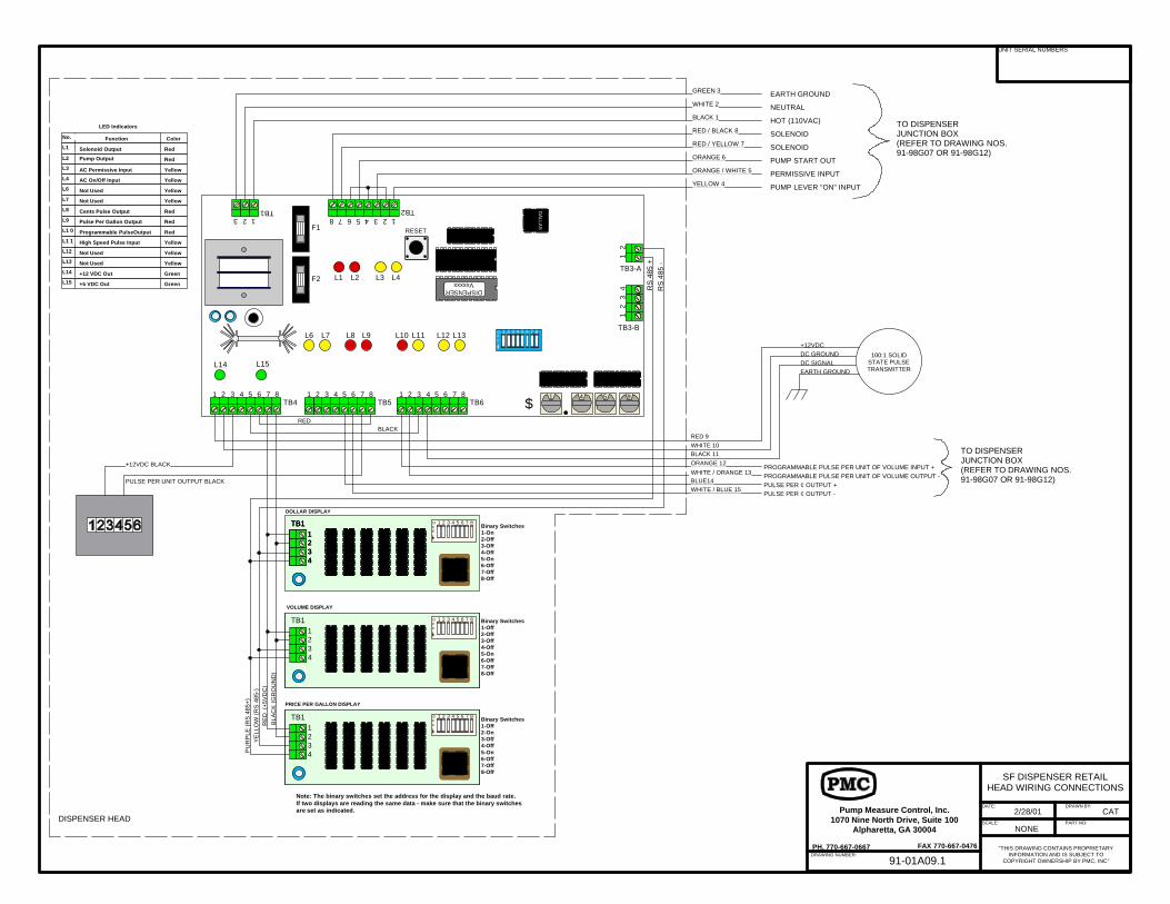
Note: The binary switches set the address for the display and the baud rate. If two displays are reading the same data - make sure that the binary switchesare set as indicated.
OFF
1 2 3 4 5 6 7 8
OFF
1 2 3 4 5 6 7 8
DISPENSER HEAD
EARTH GROUND
NEUTRAL
HOT (110VAC)
SOLENOID
SOLENOID
PUMP START OUT
PERMISSIVE INPUT
PUMP LEVER "ON" INPUT
GREEN 3
WHITE 2
BLACK 1
RED / BLACK 8
RED / YELLOW 7
ORANGE 6
ORANGE / WHITE 5
YELLOW 4
TO DISPENSERJUNCTION BOX(REFER TO DRAWING NOS.91-98G07 OR 91-98G12)
BLACK 11
RED 9WHITE 10
PULSE PER UNIT OUTPUT BLACK
+12VDC BLACK
BLUE14WHITE / BLUE 15
ORANGE 12
WHITE / ORANGE 13
RS
485
+R
S 4
85 -
REDBLACK
PU
RP
LE (
RS
485
+)Y
ELL
OW
(R
S 4
85-)
BLA
CK
(G
RO
UN
D)
RE
D (
+5V
DC
)
TO DISPENSERJUNCTION BOX(REFER TO DRAWING NOS.91-98G07 OR 91-98G12)
+12VDCDC GROUND
PROGRAMMABLE PULSE PER UNIT OF VOLUME INPUT +PROGRAMMABLE PULSE PER UNIT OF VOLUME OUTPUT -PULSE PER ¢ OUTPUT +PULSE PER ¢ OUTPUT -
DC SIGNAL
LED Indicators
Solenoid Output
Pump Output
AC Permissive Input
AC On/Off Input
Not Used
Cents Pulse Output
Pulse Per Gallon Output
Programmable PulseOutput
High Speed Pulse Input
Not Used
Not Used
+12 VDC Out
+5 VDC Out
Function Color
Not Used
Red
Red
Yellow
Yellow
Yellow
Red
Red
Yellow
Red
Yellow
Yellow
Yellow
Green
Green
L1
L2
L3
L4
L6
L7
L8
L9
L1 0
L1 1
L12
L13
L14
L15
No.
100:1 SOLIDSTATE PULSETRANSMITTEREARTH GROUND
41
23
TB3-B
DRAWING NUMBER:
DATE:
SCALE:
2/28/01Pump Measure Control, Inc.1070 Nine North Drive, Suite 100
Alpharetta, GA 30004
PH. 770-667-0667 FAX 770-667-0476
NONE
DRAWN BY:
PART NO:
CAT
"THIS DRAWING CONTAINS PROPRIETARYINFORMATION AND IS SUBJECT TO
COPYRIGHT OWNERSHIP BY PMC, INC"
SF DISPENSER RETAILHEAD WIRING CONNECTIONS
UNIT SERIAL NUMBERS
91-01A09.1
Page 51
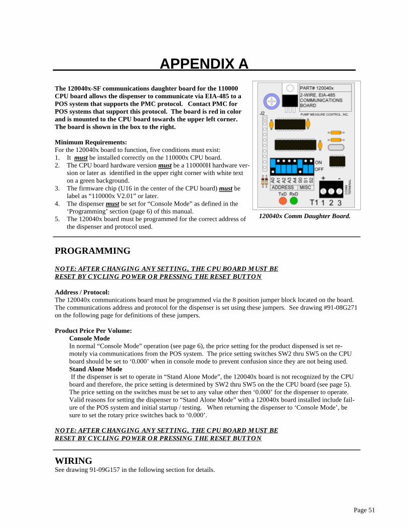
The 120040x-SF communications daughter board for the 110000 CPU board allows the dispenser to communicate via EIA-485 to a POS system that supports the PMC protocol. Contact PMC for POS systems that support this protocol. The board is red in color and is mounted to the CPU board towards the upper left corner. The board is shown in the box to the right. Minimum Requirements: For the 120040x board to function, five conditions must exist: 1. It must be installed correctly on the 110000x CPU board. 2. The CPU board hardware version must be a 110000H hardware ver-
sion or later as identified in the upper right corner with white text on a green background.
3. The firmware chip (U16 in the center of the CPU board) must be label as “110000x V2.01” or later.
4. The dispenser must be set for “Console Mode” as defined in the ‘Programming’ section (page 6) of this manual.
5. The 120040x board must be programmed for the correct address of the dispenser and protocol used.
120040x Comm Daughter Board.
APPENDIX A
PROGRAMMING NOTE: AFTER CHANGING ANY SETTING, THE CPU BOARD MUST BE RESET BY CYCLING POWER OR PRESSING THE RESET BUTTON Address / Protocol: The 120040x communications board must be programmed via the 8 position jumper block located on the board. The communications address and protocol for the dispenser is set using these jumpers. See drawing #91-08G271 on the following page for definitions of these jumpers. Product Price Per Volume:
Console Mode In normal “Console Mode” operation (see page 6), the price setting for the product dispensed is set re-motely via communications from the POS system. The price setting switches SW2 thru SW5 on the CPU board should be set to ‘0.000’ when in console mode to prevent confusion since they are not being used. Stand Alone Mode If the dispenser is set to operate in “Stand Alone Mode”, the 120040x board is not recognized by the CPU board and therefore, the price setting is determined by SW2 thru SW5 on the the CPU board (see page 5). The price setting on the switches must be set to any value other then ‘0.000’ for the dispenser to operate. Valid reasons for setting the dispenser to “Stand Alone Mode” with a 120040x board installed include fail-ure of the POS system and initial startup / testing. When returning the dispenser to ‘Console Mode’, be sure to set the rotary price switches back to ‘0.000’.
NOTE: AFTER CHANGING ANY SETTING, THE CPU BOARD MUST BE RESET BY CYCLING POWER OR PRESSING THE RESET BUTTON
WIRING See drawing 91-09G157 in the following section for details.
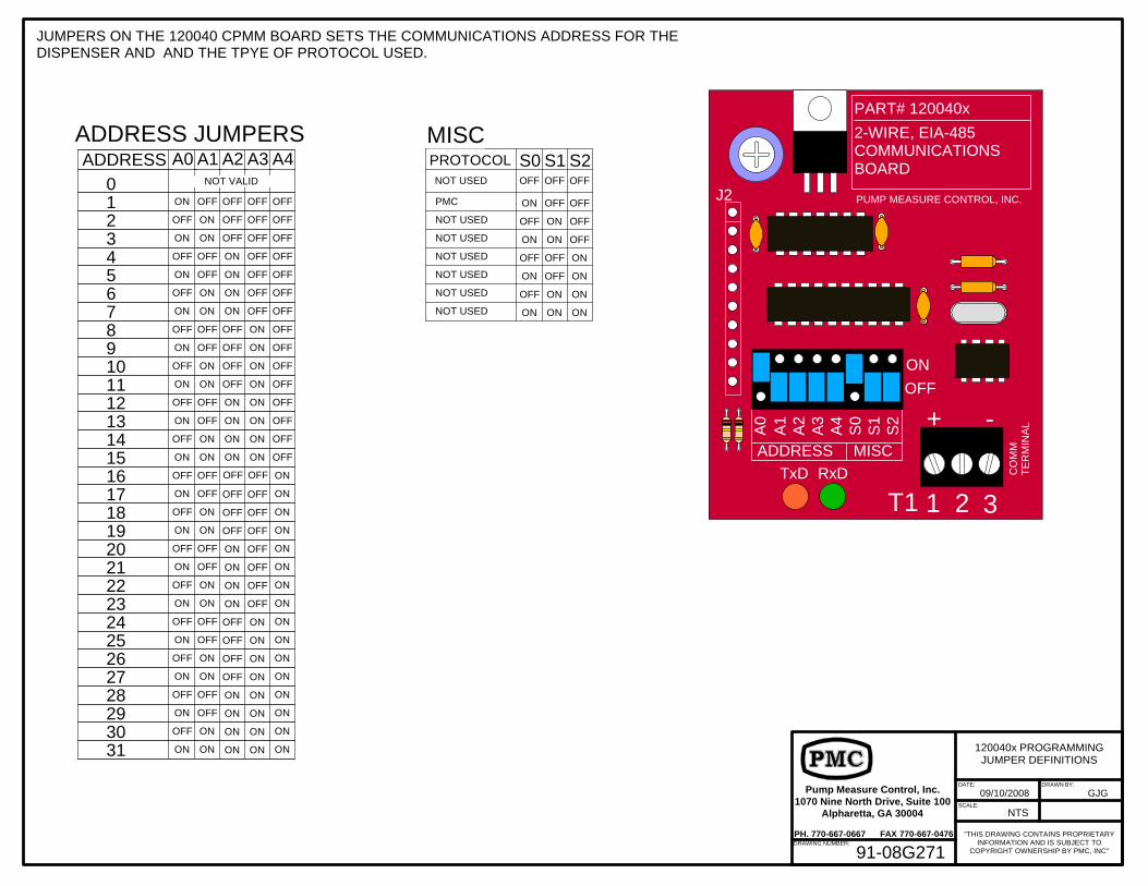
ADDRESS JUMPERSADDRESS
012345678910111213141516171819202122232425262728293031
A0 A1 A2 A3 A4
ON
NOT VALID
OFF OFF OFF OFF
OFF OFF OFF
OFF OFF OFF
OFF OFF
OFF OFF
OFF
OFF
OFF
OFF
OFF
OFF
OFF
OFF
OFF
OFF
OFF
ON
OFF
ON
OFF
ON
OFF
ON
OFF
ON
OFF
ON
OFF
ON
OFF
ON
OFF
ON
OFF
ON
OFF
ON
OFF
ON
OFF
ON
OFF
ON
OFF
ON
ON
ON
OFF
OFF
ON
ON
OFF
OFF
ON
ON
OFF
OFF
ON
ON
OFF
OFF
ON
ON
OFF
OFF
ON
ON
OFF
OFF
ON
ON
ON
ON
ON
ON
ON
ON
ON
ON
ON
ON
ON
ON
ON
ON
ON
ON
ON
ON
ON ON
ON ON
ON ON
ON ON
ON
ON
ON
ON
OFF
OFF
OFF
OFFON
OFF
OFF
OFF
OFF
ON
ON
ON
OFF OFF
OFF OFF
OFF OFF
OFF OFF
ON ON
ON ON
ON ON
ON ON
ON
ON
ON
ON
OFF
OFF
OFF
OFFON
OFF
OFF
OFF
OFF
ON
ON
ON
PROTOCOL S0 S1 S2
ON OFF OFF
OFF
OFF
OFF
OFF
ON
OFF
ON
ON
ON
OFF OFF OFF
OFF ON
OFF ON
ONONON
ON
ON
PMC
NOT USED
NOT USED
NOT USED
NOT USED
NOT USED
NOT USED
NOT USED
MISC
TxD RxD
+ -
1 2 3T1
J2
CO
MM
TE
RM
INA
L
PART# 120040x
2-WIRE, EIA-485COMMUNICATIONSBOARD
PUMP MEASURE CONTROL, INC.
OFFON
A1
A2
A3
A4
S0
S1
S2
A0
ADDRESS MISC
DRAWING NUMBER:
DATE:
SCALE:
09/10/2008Pump Measure Control, Inc.1070 Nine North Drive, Suite 100
Alpharetta, GA 30004
PH. 770-667-0667 FAX 770-667-0476
NTS
DRAWN BY:
GJG
"THIS DRAWING CONTAINS PROPRIETARYINFORMATION AND IS SUBJECT TO
COPYRIGHT OWNERSHIP BY PMC, INC"
120040x PROGRAMMINGJUMPER DEFINITIONS
91-08G271
JUMPERS ON THE 120040 CPMM BOARD SETS THE COMMUNICATIONS ADDRESS FOR THEDISPENSER AND AND THE TPYE OF PROTOCOL USED.
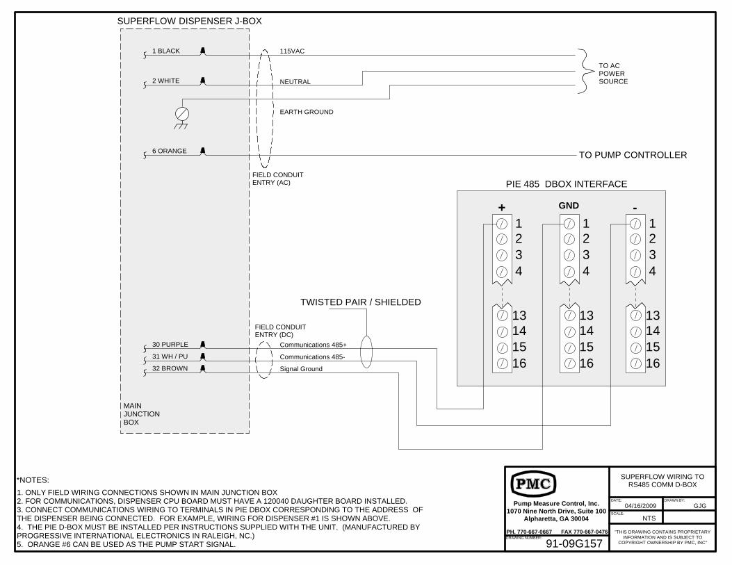
MAINJUNCTIONBOX
115VAC
NEUTRAL
EARTH GROUND
Signal Ground
FIELD CONDUITENTRY (DC)
FIELD CONDUITENTRY (AC)
TO ACPOWERSOURCE
31 WH / PU
6 ORANGE
1 BLACK
2 WHITE
SUPERFLOW DISPENSER J-BOX
PIE 485 DBOX INTERFACE
1234
13141516
1234
13141516
1234
13141516
+ -GND
32 BROWN
Communications 485+
Communications 485-
30 PURPLE
TWISTED PAIR / SHIELDED
TO PUMP CONTROLLER
DRAWING NUMBER:
DATE:
SCALE:
04/16/2009Pump Measure Control, Inc.1070 Nine North Drive, Suite 100
Alpharetta, GA 30004
PH. 770-667-0667 FAX 770-667-0476
NTS
DRAWN BY:
GJG
"THIS DRAWING CONTAINS PROPRIETARYINFORMATION AND IS SUBJECT TO
COPYRIGHT OWNERSHIP BY PMC, INC"
SUPERFLOW WIRING TORS485 COMM D-BOX
91-09G157
1. ONLY FIELD WIRING CONNECTIONS SHOWN IN MAIN JUNCTION BOX2. FOR COMMUNICATIONS, DISPENSER CPU BOARD MUST HAVE A 120040 DAUGHTER BOARD INSTALLED.3. CONNECT COMMUNICATIONS WIRING TO TERMINALS IN PIE DBOX CORRESPONDING TO THE ADDRESS OF THE DISPENSER BEING CONNECTED. FOR EXAMPLE, WIRING FOR DISPENSER #1 IS SHOWN ABOVE.4. THE PIE D-BOX MUST BE INSTALLED PER INSTRUCTIONS SUPPLIED WITH THE UNIT. (MANUFACTURED BY PROGRESSIVE INTERNATIONAL ELECTRONICS IN RALEIGH, NC.)5. ORANGE #6 CAN BE USED AS THE PUMP START SIGNAL.
*NOTES:


