Download - INSTRUCTION - Campbell Sci · Automatic Weather Station with UT20 or UT30 Instrumentation Tower

Automatic Weather Station with UT20 or UT30
Tower
Issued: 27.3.17
Copyright © 2002-2017 Campbell Scientific Ltd.
CSL 164
INS
TR
UC
TIO
N M
AN
UA
L

Guarantee
This equipment is guaranteed against defects in materials and workmanship.
We will repair or replace products which prove to be defective during the
guarantee period as detailed on your invoice, provided they are returned to us
prepaid. The guarantee will not apply to:
Equipment which has been modified or altered in any way without the
written permission of Campbell Scientific
Batteries
Any product which has been subjected to misuse, neglect, acts of God or
damage in transit.
Campbell Scientific will return guaranteed equipment by surface carrier
prepaid. Campbell Scientific will not reimburse the claimant for costs incurred
in removing and/or reinstalling equipment. This guarantee and the Company’s
obligation thereunder is in lieu of all other guarantees, expressed or implied,
including those of suitability and fitness for a particular purpose. Campbell
Scientific is not liable for consequential damage.
Please inform us before returning equipment and obtain a Repair Reference
Number whether the repair is under guarantee or not. Please state the faults as
clearly as possible, and if the product is out of the guarantee period it should
be accompanied by a purchase order. Quotations for repairs can be given on
request. It is the policy of Campbell Scientific to protect the health of its
employees and provide a safe working environment, in support of this policy a
“Declaration of Hazardous Material and Decontamination” form will be
issued for completion.
When returning equipment, the Repair Reference Number must be clearly
marked on the outside of the package. Complete the “Declaration of
Hazardous Material and Decontamination” form and ensure a completed copy
is returned with your goods. Please note your Repair may not be processed if
you do not include a copy of this form and Campbell Scientific Ltd reserves
the right to return goods at the customers’ expense.
Note that goods sent air freight are subject to Customs clearance fees which
Campbell Scientific will charge to customers. In many cases, these charges are
greater than the cost of the repair.
Campbell Scientific Ltd,
80 Hathern Road,
Shepshed, Loughborough, LE12 9GX, UK
Tel: +44 (0) 1509 601141
Fax: +44 (0) 1509 601091
Email: [email protected]
www.campbellsci.co.uk


PLEASE READ FIRST About this manual
Some useful conversion factors:
Area: 1 in2 (square inch) = 645 mm2 Length: 1 in. (inch) = 25.4 mm 1 ft (foot) = 304.8 mm 1 yard = 0.914 m 1 mile = 1.609 km
Mass: 1 oz. (ounce) = 28.35 g 1 lb (pound weight) = 0.454 kg Pressure: 1 psi (lb/in2) = 68.95 mb Volume: 1 UK pint = 568.3 ml 1 UK gallon = 4.546 litres 1 US gallon = 3.785 litres
Recycling information At the end of this product’s life it should not be put in commercial or domestic refuse but sent for recycling. Any batteries contained within the product or used during the products life should be removed from the product and also be sent to an appropriate recycling facility.
Campbell Scientific Ltd can advise on the recycling of the equipment and in some cases arrange collection and the correct disposal of it, although charges may apply for some items or territories.
For further advice or support, please contact Campbell Scientific Ltd, or your local agent.
Campbell Scientific Ltd, Campbell Park, 80 Hathern Road, Shepshed, Loughborough, LE12 9GX, UK Tel: +44 (0) 1509 601141 Fax: +44 (0) 1509 601091
Email: [email protected] www.campbellsci.co.uk


Precautions DANGER — MANY HAZARDS ARE ASSOCIATED WITH INSTALLING, USING, MAINTAINING, AND WORKING ON OR AROUND TRIPODS, TOWERS, AND ANY ATTACHMENTS TO TRIPODS AND TOWERS SUCH AS SENSORS, CROSSARMS, ENCLOSURES, ANTENNAS, ETC. FAILURE TO PROPERLY AND COMPLETELY ASSEMBLE, INSTALL, OPERATE, USE, AND MAINTAIN TRIPODS, TOWERS, AND ATTACHMENTS, AND FAILURE TO HEED WARNINGS, INCREASES THE RISK OF DEATH, ACCIDENT, SERIOUS INJURY, PROPERTY DAMAGE, AND PRODUCT FAILURE. TAKE ALL REASONABLE PRECAUTIONS TO AVOID THESE HAZARDS. CHECK WITH YOUR ORGANIZATION'S SAFETY COORDINATOR (OR POLICY) FOR PROCEDURES AND REQUIRED PROTECTIVE EQUIPMENT PRIOR TO PERFORMING ANY WORK.
Use tripods, towers, and attachments to tripods and towers only for purposes for which they are designed. Do not exceed design limits. Be familiar and comply with all instructions provided in product manuals. Manuals are available at www.campbellsci.eu or by telephoning +44(0) 1509 828 888 (UK). You are responsible for conformance with governing codes and regulations, including safety regulations, and the integrity and location of structures or land to which towers, tripods, and any attachments are attached. Installation sites should be evaluated and approved by a qualified engineer. If questions or concerns arise regarding installation, use, or maintenance of tripods, towers, attachments, or electrical connections, consult with a licensed and qualified engineer or electrician.
General • Prior to performing site or installation work, obtain required approvals and permits. Comply with all
governing structure-height regulations, such as those of the FAA in the USA. • Use only qualified personnel for installation, use, and maintenance of tripods and towers, and any
attachments to tripods and towers. The use of licensed and qualified contractors is highly recommended. • Read all applicable instructions carefully and understand procedures thoroughly before beginning work. • Wear a hardhat and eye protection, and take other appropriate safety precautions while working on or
around tripods and towers. • Do not climb tripods or towers at any time, and prohibit climbing by other persons. Take reasonable
precautions to secure tripod and tower sites from trespassers. • Use only manufacturer recommended parts, materials, and tools.
Utility and Electrical • You can be killed or sustain serious bodily injury if the tripod, tower, or attachments you are installing,
constructing, using, or maintaining, or a tool, stake, or anchor, come in contact with overhead or underground utility lines.
• Maintain a distance of at least one-and-one-half times structure height, or 20 feet, or the distance required by applicable law, whichever is greater, between overhead utility lines and the structure (tripod, tower, attachments, or tools).
• Prior to performing site or installation work, inform all utility companies and have all underground utilities marked.
• Comply with all electrical codes. Electrical equipment and related grounding devices should be installed by a licensed and qualified electrician.
Elevated Work and Weather • Exercise extreme caution when performing elevated work. • Use appropriate equipment and safety practices. • During installation and maintenance, keep tower and tripod sites clear of un-trained or non-essential
personnel. Take precautions to prevent elevated tools and objects from dropping. • Do not perform any work in inclement weather, including wind, rain, snow, lightning, etc.
Maintenance • Periodically (at least yearly) check for wear and damage, including corrosion, stress cracks, frayed cables,
loose cable clamps, cable tightness, etc. and take necessary corrective actions. • Periodically (at least yearly) check electrical ground connections.
WHILE EVERY ATTEMPT IS MADE TO EMBODY THE HIGHEST DEGREE OF SAFETY IN ALL CAMPBELL SCIENTIFIC PRODUCTS, THE CUSTOMER ASSUMES ALL RISK FROM ANY INJURY RESULTING FROM IMPROPER INSTALLATION, USE, OR MAINTENANCE OF TRIPODS, TOWERS, OR ATTACHMENTS TO TRIPODS AND TOWERS SUCH AS SENSORS, CROSSARMS, ENCLOSURES, ANTENNAS, ETC.

i
Contents
Safety Instructions ....................................................... S-1
S.1 Local Safety Regulations...................................................................... S-1
S.2 Selecting a Site for the Weather Station................................................ S-1
S.3 Before Assembly .................................................................................. S-2
S.4 Do Not Climb the Tower...................................................................... S-2
S.5 Maintenance........................................................................................ .. S-2
S.5.1 Structure ....................................................................................... S-2
S.5.2 Electrical.......................................................................................... S-2
Introduction.....................................................................I-1
I.1 Choosing the Location for Your AWS ................................................. I-1
I.2 The Effects of Varying Environmental Conditions ............................... I-2
I.2.1 The Clothesline Effect ................................................................ I-2
I.2.2 The Leading Edge Effect ........................................................... I-2
I.2.3 The Oasis Effect.......................................................................... I-2
I.3 Obstructions........................................................................................... I-3
I.4 The Effects of an Urban Environment................................................... I-3
I.5 Checking and Preparation...................................................................... I-3
Section 1. Site Preparation and Assembly of the
Tower.................................................... 1-1
1.1 Introduction........................................................................................... 1 -1
1.2 Description.............................................................................. .............. 1-3
1.2.1 Guying......................................................................................... 1-3
1.3 Tower Specifications ............................................................................ 1-3
1.3.1 Accessories.................................................................................. 1-3
1.4 Site Preparation..................................................................................... 1-4
1.5 Base Installation.................................................................................... 1-4
1.5.1 Base Installation .......................................................................... 1-4
1.5.2 Special RFM18 Base Installation................................................ 1-5
1.5.3 Lightning Protection for Roof Mounted Towers......................... 1-6
1.6 Ground Anchor Layout (for Optional Guying Kit)............................... 1-7
1.6.1 Ground Anchor Installation......................................................... 1-7
1.7 Tower Assembly ................................................................................... 1-8
1.8 Fitting AWS Components and Erecting the Tower .............................. 1-9
ii
Section 2. Assembly of Components and Erection of
Tower ....................................................... 2-1
2.1 Assess Site and Sensor Requirements.................................................. 2-1
2.2 Fitting the Mast Assembly and Lightning Rod ................................. 2-2
2.3 Fitting Equipment to the Top Tower Section....................................... 2-2
2.3.1 Fitting the Pyranometer to the Top Mast Assembly................... 2-2
2.3.2 Fitting the 011E Mounting Arm and Vector Instruments
Wind Speed/Direction Sensors ................................................... 2-4
2.3.3 017E Arm Wind Monitor Only ....................................................2-7
2.3.4 018E Arm Wind Monitor and Pyranometer............................. 2-7
2.4 Fitting Optional Guy Wires to Tower Top Section.............................. 2-7
2.5 Final Checks......................................................................................... 2-8
2.6 Tower Erection ................................................................ .................... 2-8
2.6.1 Fitting Optional Guy Wires to Ground Anchors....................... 2-9
2.7 Mounting Low Level Sensors and Other Equipment ......................... 2-10
2.7.1 Pyranometer .............................................................................. 2-10
2.7.2 Temperature/Relative Humidity Probe ..................................... 2-10
2.7.3 Mounting the Enclosure............................................................ 2-10
2.7.4 Mounting a Solar Panel............................................................. 2-11
2.8 Connections ........................................................................................ 2-12
2.8.1 Power Supply Connections....................................................... 2-12
2.8.2 Final Connections ..................................................................... 2-12
2.9 Grounding and Lightning Protection.................................................. 2-13
2.10 Maintenance...................................................................................... 2-14
2.10.1 Enclosure ................................................................................ 2-14
2.10.2 Rust Prevention....................................................................... 2-15
2.10.3 Inspection................................................................................ 2-15
2.10.4 Sensors.................................................................................... 2-15
Section 3. Programming.............................................. 3-1
3.1 Introduction .......................................................................................... 3 -1
3.1.1 Programming .............................................................................. 3-1
Appendix A. Using True North for Accurate Wind
Measurements ....................................................... A-1
A.1 Magnetic Distortion ............................................................................ A-1
A.2 Determining True North ..................................................................... A-1

iii
Figures
1-1 UT20 and UT30 Towers, showing Tower Sections ....................... 1-1
1-2 UT30 Tower Assembly, with Enclosure, Solar Panel and a
Typical Range of Sensors.................................................................... 1-2
1-3 Bottom Tower Section and Base Installation ...................................... 1-5
1-4 Special Roof Mounting Base Installation for UT30.......................... 1-6
1-5 Top View of Base and Optional Ground Anchor Layout..................... 1-7
1-6 Ground Anchor Installation.................................................................. 1-8
1-7 Fitting the Tower Sections .................................................................. 1-9
2-1 Attaching the Lightning Spike ............................................................ 2-2
2-2 Top Tower Section at Ground Level................................................... 2-3
2-3 Attaching the Top Tower Section ....................................................... 2-4
2-4 Sighting Along the Tower to Check the Magnetic Bearing ................. 2-5
2-5 Weighting the Wind Sensor Perpendicular to the Ground ................... 2-6
2-6 Both Mounting Arms and Sensors in Final Position on the
Tower Mast Assembly ........................................................................ 2-6
2-7 Installation of Guy Wires to Tower...................................................... 2-8
2-8 `Walking’ the Tower into the Upright Position.................................... 2-9
2-9 Installation of the Guy Wires to the Ground Anchors.......................... 2-9
2-10 Fitting the Enclosure ........................................................................ 2-11
2-11 Fitting the Solar Panel ...................................................................... 2-11
2-12 Grounding the Datalogger and the Tower........................................ 2-14
A-1 Declination Angles - True North to East of Magnetic North............. A-1
A-1 Declination Angles - True North to West of Magnetic North ........... A-1This
is a blank page.

S-1
Automatic Weather Station with UT20 or
UT30 Instrumentation Tower – Safety
Instructions Before you proceed with any installation work in connection with your UT20/UT30-based
station, you must read and take note of the safety recommendations given below. DO NOT
CLIMB the tower. All high-level sensors etc. must be installed with the tower at ground level.
S.1 Local Safety Regulations The UT20/UT30 are purpose-designed lattice-type towers, made from welded
aluminium.
Before you install the base and erect the tower you must ensure that the complete
installation complies with any local safety regulations covering such structures.
S.2 Selecting a Site for the Weather Station
A minimum of two people are required to safely assemble and erect
the tower and to test the sensors and other weather station
components.
The choice of location for your tower-based weather station will depend on a
number of circumstances, and these are thoroughly discussed in Section I.1 of this
manual. After selecting a suitable site you must thoroughly check the general area
for potential hazards which may occur during erection:
Ensure that ground conditions are suitable for the concrete bases which secure
the tower anchor bolts and base assembly. (See Section 1 of this manual).
Check the ground level and slope to ensure that the guy wires, if used, can be
properly fixed to give a stable installation.
Ensure that no utility services are located where you will need to dig
foundations. Check with the appropriate authorities if unsure.
Check for any obstructions, bearing in mind that the tower will need to be
raised into its final position.
Check particularly for overhead obstructions such as
power cables and other wiring. If any part of the weather
station structure comes into contact with power lines you
could be killed.
NOTE
WARNING

Automatic Weather Station with UT20/UT30 Tower
S-2
S.3 Before Assembly Before assembling the tower ensure that all parts of the tower, appropriate sensors,
tools and safety equipment are readily available. A full equipment list is given in
the Introduction Section of this manual.
Never use damaged or incorrect components. If in doubt
about the suitability of any component or equipment
please seek expert advice.
S.4 Do Not Climb The Tower Although the design of the tower produces a well made and strong structure, do
not attempt to climb the tower for any purpose.
It is possible to install and service the sensors and raise and lower the tower using
the base assembly as a hinge. A detailed explanation of how to fit the sensors and
other components while the tower is on the ground is given in Section 2 of this
manual.
DO NOT CLIMB the tower, whether guyed or unguyed, for
any reason. Carry out the fitting and maintenance of all
high-level sensors with the tower on the ground as
detailed later in this manual.
S.5 Maintenance
S.5.1 Structure
It is important to carry out maintenance at regular intervals as detailed in Section 2
of this manual in order to preserve the overall integrity of the structure. Take special
care to inspect for any rust or corrosion on the bolts, guy wires (where fitted), clips
and ground anchors, especially at ground level, where pockets of moisture may exist.
S.5.2 Electrical
Check all wiring and electrical connections regularly for signs of wear or damage,
including all earth connections.
Where mains power is involved it is essential that you
check for effective earthing of components before any
maintenance work or testing is carried out.
WARNING
WARNING
WARNING

I-1
Automatic Weather Station with
UT20/UT30 Instrumentation Tower –
Introduction Thank you for buying your weather station equipment from Campbell Scientific. This manual
includes information about siting, assembly and maintenance of a typical Automatic Weather
Station, based on the UT20 (7 metre) and UT30 (10 metre) aluminium
Antenna/Instrumentation Towers. Please read this Installation Manual carefully before
attempting to erect the tower and/or using your AWS, as it contains important information
about siting, assembly, and maintenance. You MUST read the SAFETY INSTRUCTIONS
at the front of this manual.
This manual also includes introductory information about programming. Using this
information, together with any other instruction manuals provided for specific components,
you should be able to start making measurements fairly quickly. Please remember, however,
that an AWS is sophisticated scientific equipment, and as such it may take some time for you
to become completely familiar with its use.
We recommend that you begin by reading through the entire manual to become familiar with
its content, identifying the component parts of your AWS as you do so. When you are ready
for assembly, go back a second time, and follow the instructions given.
I.1 Choosing the Location for Your AWS The siting of an Automatic Weather Station is crucial. This section briefly
describes several factors which can affect the results obtained. Please read through
this information before deciding where to locate your AWS.
The descriptions in this introductory section are general rules for all
types of weather stations and are not specific or exhaustive for any
one type; for further information, please refer to meteorological
publications.
The objective of any data collection exercise is to obtain data that is accurate,
reliable and representative. Accuracy and reliability depend mostly on the correct
selection and use of sensors. Data representativeness refers to the extent to which the
values recorded are typical of the site or location in which the sensors are placed.
Automatic weather stations are often used to provide local meteorological
measurements that otherwise could only be obtained from a ‘standard’
meteorological site, perhaps some inconvenient distance away. In this case the
AWS should be exposed in a similar way to the instruments on the standard site,
i.e. over a short grass surface that is level and not shielded by trees or buildings.
The standard site is designed to allow representative measurements of local
weather and not of a specific microclimate. It is important that the instruments are
positioned at a similar height to those on other meteorological sites; in the UK,
measurements of air temperature and humidity are normally made with a
Stevenson Screen at 1.2 m above the ground. A standard height for anemometers
on such a site is 10 m, but 2-3 m is considered acceptable for semi-permanent
installations.
NOTE

Automatic Weather Station with UT20/UT30 Tower
I-2
In other cases, an AWS is required to measure the true conditions at a site —
possibly to determine how much these differ from the standard conditions
measured over a regional network of meteorological stations. Here, the AWS
should be exposed over a relatively uniform area of terrain. Some care is required
in interpreting the measurements obtained, however, because gradients of air
temperature, humidity and wind speed increase as the distance from the surface
decreases.
As an example, consider an AWS sited in a crop of newly planted corn with the
anemometer 2 m above the ground. The measured wind speed will decrease
markedly as the crop grows because the distance between the instrument and the
surface is continually reducing. At harvest the anemometer may be only 20 or
30 cm above the upper foliage and the measured wind speed will be slow. This is a
true representation of conditions at the height of the anemometer; it is effectively a
microclimatic measurement that is not representative of the general conditions in
the region.
I.2 The Effects of Varying Environmental Conditions This section describes three ways in which local conditions such as moisture or the
presence of vegetation can affect the measurements taken by an AWS. These
effects are well documented and further details can be found in the meteorological
literature.
I.2.1 The Clothesline Effect
The ‘clothesline effect’ in its simplest form describes the effect of air passing from
dry, unvegetated surfaces to moist, vegetated surfaces and the consequent effect on
vapour gradients and heat transfer. This should be carefully considered when siting
an AWS in crops or near trees when the wind direction is mostly towards the
vegetation.
I.2.2 The Leading Edge Effect
This effect occurs when air moves over a surface that differs in temperature,
moisture content, roughness or some other characteristic from an adjacent surface.
The line of discontinuity is known as the leading edge. As air passes over the
leading edge its characteristics gradually adjust to the new surface. This internal
boundary layer varies in vertical extent with distance from the leading edge. A
transitional zone exists where the air is modified but not adjusted to the new
surface. These effects become most pronounced when advection (horizontal air
flow) is strongest. There are no universally accepted figures for the height of this
internal boundary layer as it is influenced by the nature of the surface and the
extent of any advection.
I.2.3 The Oasis Effect
The ‘oasis effect’ occurs when an isolated moisture source is surrounded by an
otherwise arid region. If the wind direction is such that moist air is drawn from the
surface of the water body (or other water source such as a glacier or area of
vegetation), then the relative humidity measurements do not represent the general
conditions in the region.
Section I. Introduction
I-3
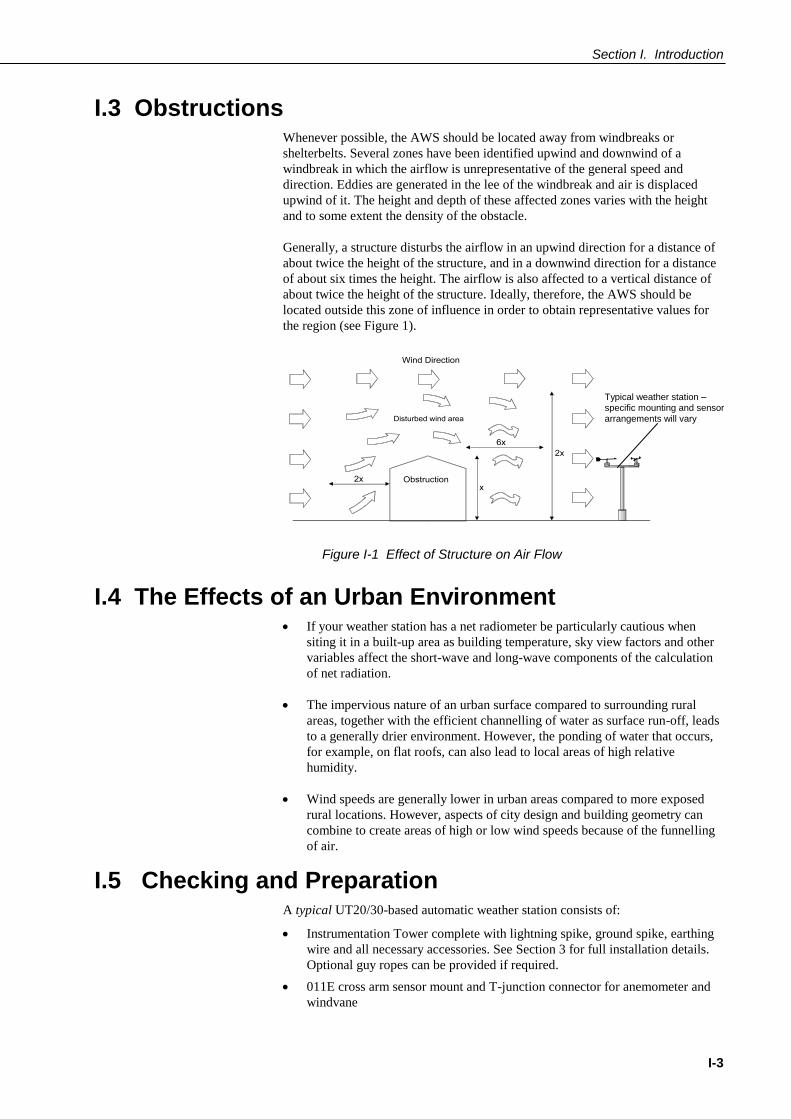
I.3 Obstructions Whenever possible, the AWS should be located away from windbreaks or
shelterbelts. Several zones have been identified upwind and downwind of a
windbreak in which the airflow is unrepresentative of the general speed and
direction. Eddies are generated in the lee of the windbreak and air is displaced
upwind of it. The height and depth of these affected zones varies with the height
and to some extent the density of the obstacle.
Generally, a structure disturbs the airflow in an upwind direction for a distance of
about twice the height of the structure, and in a downwind direction for a distance
of about six times the height. The airflow is also affected to a vertical distance of
about twice the height of the structure. Ideally, therefore, the AWS should be
located outside this zone of influence in order to obtain representative values for
the region (see Figure 1).
Figure I-1 Effect of Structure on Air Flow
I.4 The Effects of an Urban Environment If your weather station has a net radiometer be particularly cautious when
siting it in a built-up area as building temperature, sky view factors and other
variables affect the short-wave and long-wave components of the calculation
of net radiation.
The impervious nature of an urban surface compared to surrounding rural
areas, together with the efficient channelling of water as surface run-off, leads
to a generally drier environment. However, the ponding of water that occurs,
for example, on flat roofs, can also lead to local areas of high relative
humidity.
Wind speeds are generally lower in urban areas compared to more exposed
rural locations. However, aspects of city design and building geometry can
combine to create areas of high or low wind speeds because of the funnelling
of air.
I.5 Checking and Preparation A typical UT20/30-based automatic weather station consists of:
Instrumentation Tower complete with lightning spike, ground spike, earthing
wire and all necessary accessories. See Section 3 for full installation details.
Optional guy ropes can be provided if required.
011E cross arm sensor mount and T-junction connector for anemometer and
windvane
Typical weather station – specific mounting and sensor arrangements will vary
Automatic Weather Station with UT20/UT30 Tower
I-4
A100R wind speed sensor (anemometer)
W200P wind direction sensor
016E pyranometer support arm
SP1110 pyranometer with SKE211 levelling fixture
HMP45C air temperature and relative humidity sensor with URS1
Unaspirated Radiation Shield
ARG100 tipping bucket raingauge
Fibreglass enclosure with integral power supply (for the datalogger)
CR10X or CR1000 datalogger.
This equipment list represents a typical configuration. Your weather
station may have different or additional sensors, or you may have a
lead-acid power supply with a solar panel. If you have any difficulty
assembling or using your weather station after reading this
Installation Manual please contact Campbell Scientific for help.
The minimum equipment you will need for satisfactory installation is as follows:
A spirit level
A tape measure
A hard hat
Industrial quality gloves and footwear
Rustproofing compound for threads
An adjustable spanner
A range of standard and Phillips screwdrivers
A compass (for wind direction orientation)
Cable ties (supplied)
A set of Allen hex keys (at least a 3/16")
Suitable lengths of appropriate cable for:
a) The connection of the AC adaptors (AC-ADAPT and AC-ADAPT2)
to the PS100E charger and power supply unit
b) The interconnection of short haul modems
c) The extension of telephone cables to the datalogger enclosure.
If you do not have a remote communications link to the weather station, you will
also need the following items to test a system:
Either
A CR10KD or CR1000 Keyboard/Display (connected to the datalogger with
an SC12 cable)
or
A laptop PC with PC200W, PC400 or LoggerNet software installed
(connected to the datalogger with either an SC32A interface + SC25AT cable
+ SC12 cable or an SC929 interface cable).
Additional items may be needed depending on the nature of the installation. These
are given in the appropriate section, but may include:
A mallet (for driving in ground spike)
Silicone rubber sealant
A protractor (for adjusting solar panel angle)
NOTE
Section I. Introduction
I-5
Step ladders (for installing sensors and levelling pyranometer)
Pipe Wrench
Shovel, pickaxe and trowel for making the concrete base foundations.
Materials to make the foundations (wood formers, concrete mixture etc.)
Wire rope cutter (if using guy ropes on your installation)
A length of rope to assist in raising the tower.
There should be a minimum of two people on site for the safe installation and
setting up of a complete tower-based weather station.


1-1
Section 1. Site Preparation and Assembly
of the Tower Before starting any work on your UT20 or UT30-based weather station, please read the
SAFETY INSTRUCTIONS at the front of this manual.
This section describes the site preparation for, and preliminary assembly of, the
Instrumentation Tower.
See Section 2 for the assembly of sensors and other components and the final erection of the
tower. Section 2 also details the procedure for guying the tower where this is required and
where the optional guying kit is provided.
1.1 Introduction The UT20 and UT30 are tubular aluminium towers with two (UT20) or three
(UT30) main sections plus a mast assembly, giving an overall height of
approximately 7 m and 10 m respectively. The sections are triangular in cross-
section and consist of three aluminium tubes braced by continuous aluminium rod
welded in a multiple ‘Z’ pattern. This gives a very low overall weight and the tower
can easily be erected. Optional guy rope assemblies can be supplied where required.
Figure 1-1 UT20 and UT30 Towers, showing Tower Sections
Mast Assembly
Leg Assembly

Automatic Weather Station with UT20/UT30 Tower
1-2
Figure 1-2 UT30 Tower Assembly, with Enclosure, Solar Panel and a Typical Range of Sensors
Middle Section
Mast Assembly
Top Section
Middle Section
Bottom Section
Hinged Mounting Base Assembly (concreted into the ground)
Tower shown with optional guying kit
Section 1. Site Preparation and Tower Assembly
1-3
1.2 Description The tower sections are made from 32 mm (1¼") OD aluminium tube. The mast is
made from the same material but is reduced to 25 mm (1") OD for the top 450 mm
to accommodate the 405-1, 016E, 017E or 018E crossarm. Two bolts are used to
secure the mast to the collar in the top section of the tower.
The towers are designed for use with special base assemblies, which are embedded
in concrete (see Figure 1-3). Roof-mount base assemblies, for mounting onto
suitably constructed roof areas or other flat surfaces (see Figure 1-4), are available
to special order. Please contact Campbell Scientific for further advice.
1.2.1 Guying
Standard towers are not supplied with guy ropes. If your particular site is subject
to consistently high wind speeds or turbulence, a guy rope assembly kit can be
supplied to minimise vibration effects on the tower and instrumentation.
Section 2 of this manual gives full instructions for guying the tower where
required.
Do not attempt to climb the structure (whether guyed or
not) either to do initial installation or to carry out routine
maintenance of components. All installation and
maintenance must be done with the tower at ground level
as detailed in Section 2 of this manual.
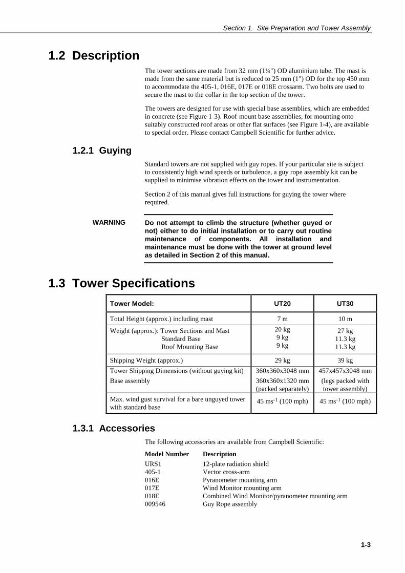
1.3 Tower Specifications
Tower Model: UT20 UT30
Total Height (approx.) including mast 7 m 10 m
Weight (approx.): Tower Sections and Mast
Standard Base
Roof Mounting Base
20 kg
9 kg
9 kg
27 kg
11.3 kg
11.3 kg
Shipping Weight (approx.) 29 kg 39 kg
Tower Shipping Dimensions (without guying kit)
Base assembly
360x360x3048 mm
360x360x1320 mm
(packed separately)
457x457x3048 mm
(legs packed with
tower assembly)
Max. wind gust survival for a bare unguyed tower
with standard base 45 ms-1 (100 mph) 45 ms-1 (100 mph)
1.3.1 Accessories
The following accessories are available from Campbell Scientific:
Model Number Description
URS1 12-plate radiation shield
405-1 Vector cross-arm
016E Pyranometer mounting arm
017E Wind Monitor mounting arm
018E Combined Wind Monitor/pyranometer mounting arm
009546 Guy Rope assembly
WARNING
Automatic Weather Station with UT20/UT30 Tower
1-4
1.4 Site Preparation
You are recommended to take a full tool set of metric and imperial spanners on
site. Minimum requirements are given in the following sections.
Always take sensible precautions during installation of any metalwork. We recommend that you use industrial quality gloves and protective footwear to minimise the possibility of minor injuries.
1.5 Base Installation Choose the location of your tower base carefully, remembering that you will need
sufficient space to assemble the tower on the ground before attaching it to the
hinged base and ‘walking’ it into its upright position.
The base sections for the UT20 and UT30 differ slightly in design – the UT30 uses
three separate legs, whereas the UT20 base is an integrated assembly. The
following instructions generally illustrate the UT30 base, but the UT20 base is
fitted in a similar way.
If you will be using the optional guy rope assembly, you will also need to consider
the positions of the guy anchors – please refer to Section 1.6, below.
NEVER place any aluminium tower section directly into a concrete base. The corrosive effects of the concrete on aluminium will damage the tower and void the warranty. Use only the steel base/leg assemblies as shown below. You must also ensure good water drainage for the aluminium tubing on all the tower sections to minimise the possibility of trapped water freezing (and possibly causing splits in the tubing). The supplied bases allow for adequate drainage; you must ensure that the bottom openings of the aluminium tubes do not become blocked. (The steel legs can, however, be suitably treated to prevent water ingress and to minimise rusting.)
1.5.1 Base Installation
For a base installation you will need:
A shovel
A pickaxe
A spirit level
A 4 metre tape measure
A hammer
A concrete trowel
Two 9/16" open-ended spanners
Locate where the tower base is to be installed and place the tower sections end to
end in the correct order of assembly. Make sure enough clearance exists so that the
tower can later be ‘walked’ up to its upright position without overhead
interference.
CAUTION
CAUTION
Section 1. Site Preparation and Tower Assembly
1-5
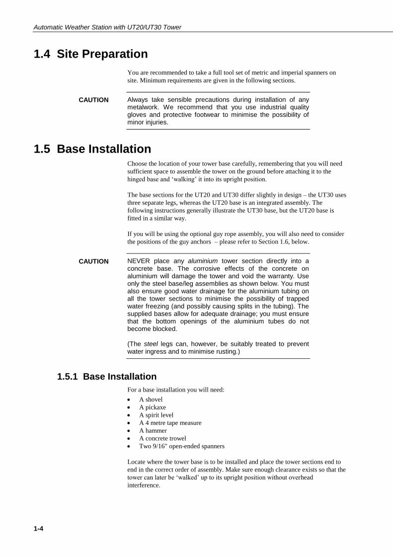
Dig a hole 900 mm square by 1200 mm deep. Install the bottom section of the
tower to the base using two bolts per leg, making sure that all three legs are fitted
to allow for tilt in the same direction – see Figure 1-3.
Set the base, with the bottom tower section attached, into the hole. Orient the
tower for the proper tilt direction, and make sure that the upper round flanges on
the legs will be at approximately 12 mm above the finished height of the concrete
(see Figure 1-3).
It is very important to ensure that the bottom tower section is vertical. As concrete
is poured into the hole, periodically check that the tower is vertical using a spirit
level and make adjustments as necessary. Allow three to four days for the concrete
to cure.
Figure 1-3 Bottom Tower Section and Base Installation
1.5.2 Special Roof-Mounting Base Installation
The roof-mounting base has been designed for mounting to flat surfaces such as
flat concrete slabs or flat roofs. For installation you will need:
Three suitable bolts or other mounting anchors
A 9/16" open-end spanner
A spirit level
A guying kit and fixing points to the roof
Check that tower is vertical with a spirit level
12 mm approx. Upper flanges on legs (UT30)
Ensure that bolts are fitted so that all three legs can tilt the same way
To tilt the tower, remove both bolts from leg A. (see above). Remove the lower bolts and loosen the upper bolts in the other two legs.
Leg A

Automatic Weather Station with UT20/UT30 Tower
1-6
You must take careful consideration of site conditions and roof construction (if roof mounted) before installing the roof-mount base. If you are at all unsure about the construction or structural integrity of the roof, you must seek expert advice before attempting to mount the base. We recommend roof mounted masts must be guyed.
Locate where the tower base is to be installed and place the tower sections end to
end in the correct order of assembly. Make sure that enough clearance exists so
that the tower can later be ‘walked’ up to its upright position without overhead
interference.
As with a ground mounted installation, you must check
particularly for overhead obstructions such as power
cables and other wiring around the building. If any part of
the weather station structure comes into contact with
power lines you could be badly injured or killed.
Attach the bottom section of the tower to the base using one bolt per leg. Stand the
base and tower section upright, and orient for the proper tilt direction (see Figure
1-4). Install the base to the roof using three lag bolts, or other anchors appropriate
for the application (see Caution above). Before tightening the bolts, check that the
tower is vertical and add shims or other packing material to the base if necessary.
Figure 1-4 Special Roof-Mounting Base Installation for UT30
1.5.3 Lightning Protection for Roof Mounted Towers
You will be supplied with a standard lightning/grounding kit as detailed in Section
2.9 of this manual. Both the main and secondary grounding wires are intended to
reach to a grounding spike adjacent to the tower. For a roof mounted tower it is
your responsibility to make suitable arrangements for the grounding wires to be
properly grounded. This may be by connecting them to existing lightning
protection equipment on the building, or, alternatively, by running a new
grounding wire down the building to the ground spike or other suitable grounding
point. If you are unsure about the provision of adequate lightning protection, you
should seek expert advice.
CAUTION
WARNING
Check that tower is vertical with spirit level

Section 1. Site Preparation and Tower Assembly
1-7
1.6 Ground Anchor Layout (for Optional Guying Kit) If you are using the optional guying kit, you will need to consider the overall site
layout both for the tower position and the siting of the guy anchors as detailed
below.
To lay out the base installation with optional guy anchors you will need:
A 15 metre tape measure
Four stakes
6 metres of non-stretch line
Figure 1-5 shows the layout of the guy anchors in relationship to the tower base.
To mark the positions of the guy anchors:
1. Drive a stake into the ground where the tower is to be located.
2. Attach a line to the stake and scribe a circle with a 3.6 metre radius (for
UT20) or a 5.2 metre radius (for UT30).
3. Choose a tilt direction for the tower.
4. From the centre point, walk in the opposite direction and drive a stake into the
ground on the scribed line (see Figure 1-5). This marks the position of the rear
leg anchor.
5. Locate the other anchor points by measuring 6.2 metres (UT20) or 9 metres
(UT30) from the rear tower leg anchor stake to the scribed line.
C
CENTER
Centre Point
Tilt Direction
Anchor Location
120°
9m 9m
5.2m Radius
Anchor Location
Rear Anchor Location
Figure 1-5 Top View of Base and Optional Ground Anchor Layout
1.6.1 Ground Anchor Installation
To install the ground anchors you will need:
A shovel
A pickaxe
A 3 metre tape measure
A concrete trowel
3.6m rad. (UT20)
5.2m rad. (UT30) 6.2m (UT20)
9.0m (UT30)
6.2m (UT20)
9.0m (UT30)
Automatic Weather Station with UT20/UT30 Tower
1-8
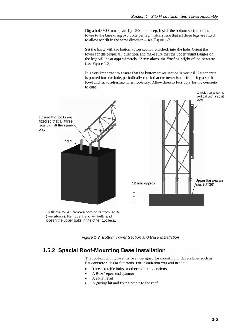
Locate the three anchor points (see Figure 1-5) and dig three holes 600 mm square
by 600 mm deep. Fill the holes with concrete and install the eyebolts as shown in
Figure 1-6.
Figure 1-6 Ground Anchor Installation
1.7 Tower Assembly To install the tower and guy ropes (if fitted) you will need:
Two 9/16" open end spanners
A 9/16" socket and ratchet
A tape measure
A 1/8" Allen Key
A flat blade screwdriver
UV-resistant wire ties
A pair of cutters
A 7 mm nut driver
A pair of wire rope cutters
A spirit level
A pair of pliers
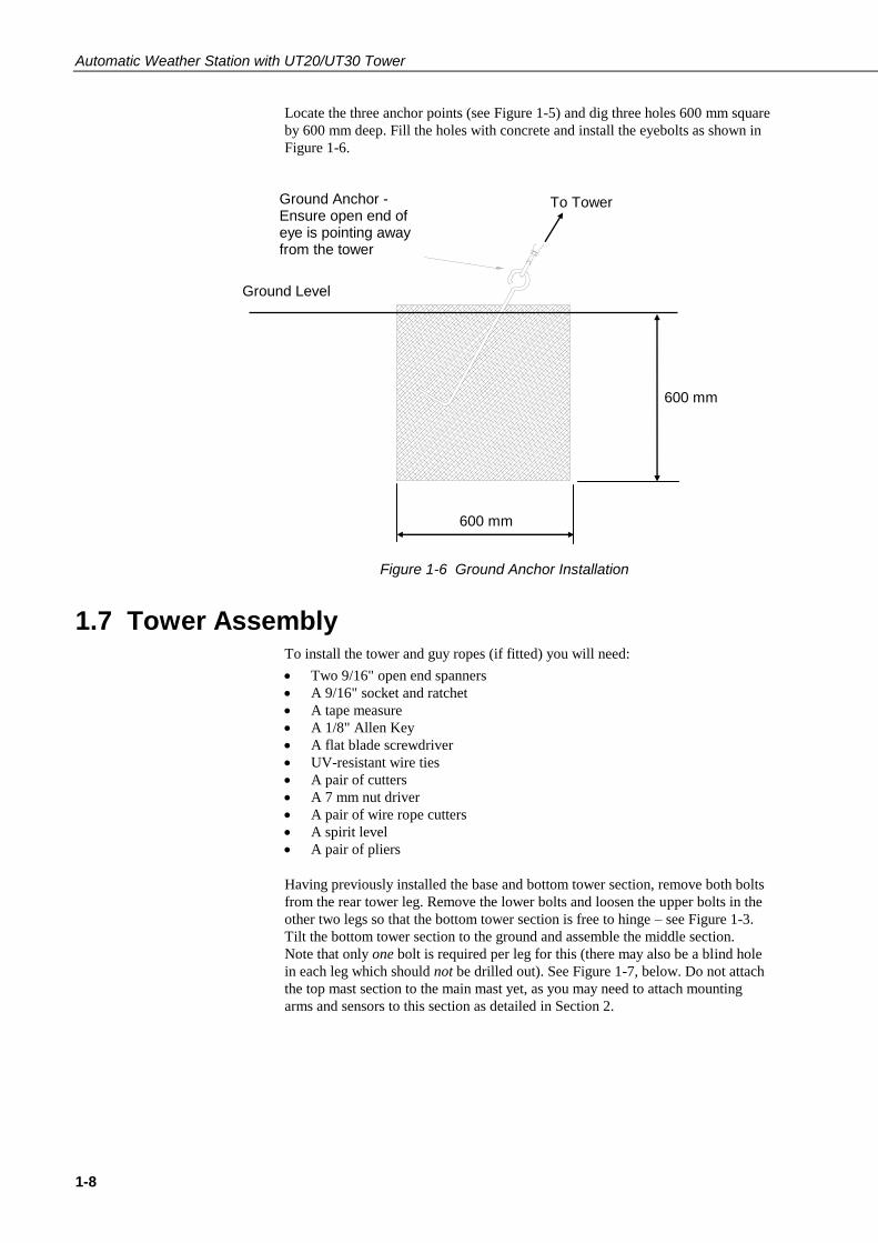
Having previously installed the base and bottom tower section, remove both bolts
from the rear tower leg. Remove the lower bolts and loosen the upper bolts in the
other two legs so that the bottom tower section is free to hinge – see Figure 1-3.
Tilt the bottom tower section to the ground and assemble the middle section.
Note that only one bolt is required per leg for this (there may also be a blind hole
in each leg which should not be drilled out). See Figure 1-7, below. Do not attach
the top mast section to the main mast yet, as you may need to attach mounting
arms and sensors to this section as detailed in Section 2.
To Tower
Ground Level
600 mm
600 mm
Ground Anchor - Ensure open end of eye is pointing away from the tower
Section 1. Site Preparation and Tower Assembly
1-9
Figure 1-7 Fitting the Tower Sections
1.8 Fitting AWS Components and Erecting the Tower Section 2 of this manual details the fitting of sensors and other equipment, and the
final erection and guying of the tower.
Use one bolt per leg


2-1
Section 2. Assembly of Components and
Erection of Tower
This section gives details of how to fit, level and align typical sensors and ancillary equipment
and how to erect the tower and fit the optional guy wires.
Before fitting components or erecting the tower, please read the SAFETY INSTRUCTIONS
at the front of this manual.
Some sensors (especially those that will be mounted at the top of the tower, such as
windvanes, etc.) must be fitted and levelled/aligned while the tower is at ground level, before
it is raised. This section discusses the correct way to achieve this, as well as giving assembly
instructions for other sensors plus the solar panel and the enclosure, which can be fitted after
the tower is raised.
2.1 Assess Site and Sensor Requirements Each site will have its own individual requirements, but, before attaching any
sensors and equipment to the tower, you should give some consideration on where
to mount them. Some sensors, such as windvanes, will need to be mounted at the
top of the tower. Other sensors and equipment, such as radiation monitors, solar
panels and enclosures can be mounted at various levels. You should assess the
requirements for your particular site, weighing the need for periodic
maintenance/ease of access against possible anti-vandalism measures, etc. For
instance, a radiation monitor or pyranometer could be mounted at a high level (to
deter vandalism and give better exposure to light), but this would make periodic
maintenance, such as cleaning, more difficult and you may wish to mount such
instruments at a lower level, accessible directly from the ground or by using a step-
ladder.
1. This manual does not cover sensors which will not be mounted
on the tower itself (e.g. tipping bucket raingauge) or which are
not part of a standard weather station (e.g. snow depth gauge).
For installation details of these sensors, please refer to the
manuals provided with them, or contact Campbell Scientific for
assistance.
2. Different types of mounting arm are described in this section.
Most weather stations will not require all of these arms. Where
more than one arm is fitted (e.g. an 011E and an 016E), ensure
that the wind sensors are mounted on the higher arm so that any
other arms do not affect wind measurements.
3. You may wish, where possible, to pre-assemble certain
components in a workshop or other sheltered place before final
assembly in the field. This could save time and frustration when
assembling and fitting in less favourable circumstances. Such
tasks include, for example, securing the Relative Humidity
sensor inside its radiation shield and attaching other sensors
loosely to their mounting arms ready for final adjustment.
Once the tower base has been installed, all the sensors and other components which
will be mounted beyond easy reach should be assembled, attached to the tower and
aligned while the tower is still on the ground (as described in this section) before
the tower is raised.
NOTES
Automatic Weather Station with UT20/UT30 Tower
2-2
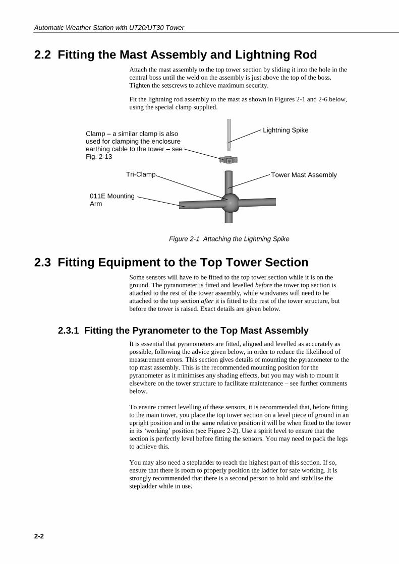
2.2 Fitting the Mast Assembly and Lightning Rod Attach the mast assembly to the top tower section by sliding it into the hole in the
central boss until the weld on the assembly is just above the top of the boss.
Tighten the setscrews to achieve maximum security.
Fit the lightning rod assembly to the mast as shown in Figures 2-1 and 2-6 below,
using the special clamp supplied.
Figure 2-1 Attaching the Lightning Spike
2.3 Fitting Equipment to the Top Tower Section Some sensors will have to be fitted to the top tower section while it is on the
ground. The pyranometer is fitted and levelled before the tower top section is
attached to the rest of the tower assembly, while windvanes will need to be
attached to the top section after it is fitted to the rest of the tower structure, but
before the tower is raised. Exact details are given below.
2.3.1 Fitting the Pyranometer to the Top Mast Assembly
It is essential that pyranometers are fitted, aligned and levelled as accurately as
possible, following the advice given below, in order to reduce the likelihood of
measurement errors. This section gives details of mounting the pyranometer to the
top mast assembly. This is the recommended mounting position for the
pyranometer as it minimises any shading effects, but you may wish to mount it
elsewhere on the tower structure to facilitate maintenance – see further comments
below.
To ensure correct levelling of these sensors, it is recommended that, before fitting
to the main tower, you place the top tower section on a level piece of ground in an
upright position and in the same relative position it will be when fitted to the tower
in its ‘working’ position (see Figure 2-2). Use a spirit level to ensure that the
section is perfectly level before fitting the sensors. You may need to pack the legs
to achieve this.
You may also need a stepladder to reach the highest part of this section. If so,
ensure that there is room to properly position the ladder for safe working. It is
strongly recommended that there is a second person to hold and stabilise the
stepladder while in use.
Clamp – a similar clamp is also used for clamping the enclosure earthing cable to the tower – see Fig. 2-13
Lightning Spike
Tower Mast Assembly Tri-Clamp
011E Mounting Arm

Section 2. Assembly of Components and Erection of Tower
2-3
Figure 2-2 Top Tower Section at Ground Level
The standard mounting arm supplied with the pyranometer is the 016E, and the
pyranometer is normally mounted on the tower top mast assembly (as shown in
Figure 2-6, below) as this will effectively eliminate shading problems from the
tower structure. However, cleaning and other maintenance requirements will
necessitate lowering the tower to the ground, and so, for easier maintenance, you
may wish to mount the pyranometer lower down the structure so that it is
accessible either directly from the ground or by using a step-ladder. In this case,
care should be taken that the pyranometer is mounted so that there is minimal
shading from the tower structure at all times. In the Northern hemisphere, the
pyranometer should be facing due South to help achieve this.
The mounting arm is supplied complete with a special ‘tri-clamp' which is suitable
for both top mast fitting or fitting onto the main tower structure. The following
section gives details of mounting the pyranometer on the top mast assembly.
Section 2.7 describes mounting it on the tower structure at a lower level.
With the top tower section correctly levelled and oriented as shown in Figure 2-2,
complete the assembly as follows:
1. Attach the pyranometer to the levelling fixture.
2. Fix the levelling fixture to the mounting arm with the two diametrically
opposed bolts and secure it with the nuts below the plate. Only tighten the nuts
finger-tight until the pyranometer has been levelled, as detailed below.
3. Approximately level the sensor – this may be by using three wing nuts or
standard hexagon head nuts, depending on the model of the sensor.
Place top tower section onto level ground, packing if necessary to achieve good vertical and horizontal alignment when checked with a spirit level, before adding arms and sensors.
IMPORTANT - Position so that this
section is in the same relative
position it will be in after final
assembly and erection, to ensure
that sensors will be in the correct
working orientation.
Top Mast Assembly - slide into top mast section and tighten setscrews

Automatic Weather Station with UT20/UT30 Tower
2-4
4. Attach the mounting arm and pyranometer to the top mast assembly with the
universal mounting bracket, as shown in Figure 2-6. Orient the arm to face
approximately south relative to the tower to minimise the possibility of any part
of the structure or other instruments casting a shadow onto the pyranometer.
5. Make final adjustments for level and orientation, and fully secure the
pyranometer to the arm, and the arm to the mast.
6. Slide the whole top tower section into place on the main tower, and secure with
the bolts supplied (see Figure 2-3). This will need to be done with extreme care
in order to avoid altering the alignment and levelling of the pyranometer.
7. The windset should now be fitted to the top mast assembly, before the tower is
raised, as outlined in the following section.
Figure 2-3 Attaching the Top Tower Section
If you are not mounting the pyranometer on the top mast assembly as
described above, you should mount the arm to face approximately
south relative to the tower and always bear in mind, and attempt to
minimise, any possible shading effects of the structure on the
pyranometer. See Section 2.6.
2.3.2 Fitting the 011E Mounting Arm and Vector Instruments
Wind Speed/Direction Sensors
The 011E cross-arm sensor mount is supplied with a special tri-clamp connector
and is attached to the tower top mast assembly, above the pyranometer (if fitted).
See Figure 2-6, below.
As it is essential that the windset is set up and mounted as accurately as possible, it
must be attached to the tower mast assembly and aligned while the tower is lying
flat along the ground. The procedure outlined below must be followed exactly to
ensure that your windset will provide accurate and reliable readings.
1. Assemble the windset components on their mounting arm and lightly secure.
2. Ensure that the tower structure is lying flat along the ground in an
approximately horizontal position. You may need to pack the structure to
achieve this.
NOTE
Top Mast Section complete with pyranometer etc.
Section 2. Assembly of Components and Erection of Tower
2-5
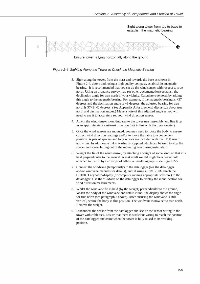
Figure 2-4 Sighting Along the Tower to Check the Magnetic Bearing
3. Sight along the tower, from the mast end towards the base as shown in
Figure 2-4, above and, using a high quality compass, establish its magnetic
bearing. It is recommended that you set up the wind sensor with respect to true
north. Using an ordnance survey map (or other documentation) establish the
declination angle for true north in your vicinity. Calculate true north by adding
this angle to the magnetic bearing. For example, if the magnetic bearing is +37
degrees and the declination angle is +3 degrees, the adjusted bearing for true
north is 37+3=40 degrees. (See Appendix A for a general discussion about true
north and declination angles.) Make a note of this adjusted angle as you will
need to use it to accurately set your wind direction sensor.
4. Attach the wind sensor mounting arm to the tower mast assembly and line it up
in an approximately east/west direction (not in line with the pyranometer).
5. Once the wind sensors are mounted, you may need to rotate the body to ensure
correct wind direction readings and/or to move the cable to a convenient
position. A pair of spacers and long screws are included with the 011E arm to
allow this. In addition, a nylon washer is supplied which can be used to stop the
spacer and screw falling out of the mounting arm during installation.
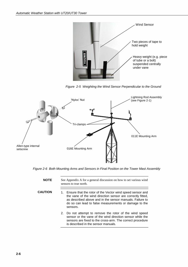
6. Weight the fin of the wind sensor, by attaching a weight of some kind, so that it is
held perpendicular to the ground. A makeshift weight might be a heavy bolt
attached to the fin by two strips of adhesive insulating tape – see Figure 2-5.
7. Connect the windvane (temporarily) to the datalogger (see the datalogger
and/or windvane manuals for details), and, if using a CR10/10X attach the
CR10KD keyboard/display (or computer running appropriate software) to the
datalogger. Use the *6 Mode on the datalogger to display the input location for
wind direction measurements.
8. Whilst the windvane fin is held (by the weight) perpendicular to the ground,
loosen the body of the windvane and rotate it until the display shows the angle
for true north (see paragraph 3 above). After ensuring the windvane is still
vertical, secure the body in this position. The windvane is now set to true north.
Remove the weight.
9. Disconnect the sensor from the datalogger and secure the sensor wiring to the
tower with cable ties. Ensure that there is sufficient wiring to reach the position
of the datalogger enclosure when the tower is fully raised to its working
position.
Ensure tower is lying horizontally along the ground
Sight along tower from top to base to establish the magnetic bearing
Automatic Weather Station with UT20/UT30 Tower
2-6
Figure 2-5 Weighting the Wind Sensor Perpendicular to the Ground
Figure 2-6 Both Mounting Arms and Sensors in Final Position on the Tower Mast Assembly
See Appendix A for a general discussion on how to set various wind
sensors to true north.
1. Ensure that the rotor of the Vector wind speed sensor and the vane of the wind direction sensor are correctly fitted, as described above and in the sensor manuals. Failure to do so can lead to false measurements or damage to the sensors.
2. Do not attempt to remove the rotor of the wind speed sensor or the vane of the wind direction sensor while the sensors are fixed to the cross-arm. The correct procedure is described in the sensor manuals.
NOTE
CAUTION
Lightning Rod Assembly (see Figure 2-1)
011E Mounting Arm
016E Mounting Arm
Wind Sensor
Two pieces of tape to hold weight
Heavy weight (e.g. piece of tube or a bolt) suspended centrally under vane
Tri-clamps
‘Nyloc’ Nut
Allen-type internal setscrew
Section 2. Assembly of Components and Erection of Tower
2-7
2.3.3 017E Arm — Wind Monitor Only
This simple sensor mounting arm is supplied with two tri-clamps and a mounting
tube for the Wind Monitor. Mount the 017E as follows:
1. Ensure that the tower is lying flat along the ground as detailed above for the
011E mounting arm.
2. Position one tri-clamp at each end of the arm.
3. Position the arm, using a tri-clamp, onto the tower mast assembly and adjust
the position of the arm so that the eventual height of the Wind Monitor
propeller will be in the correct orientation. Fully tighten the setscrew in the tri-
clamp with an Allen key.
4. Fit the Wind Monitor mounting tube (supplied with the 017E) to the Wind
Monitor and tighten the stainless steel clamp to hold it in place.
5. Assemble the Wind Monitor using a tri-clamp connector at the end of the 017E.
6. Check that the Wind Monitor rotates freely and is perpendicular to the ground,
and fully tighten the Allen screw in the tri-clamp.
7. Generally align the Wind Monitor to true North following the instructions
given for the 011E arm above, and in Appendix A.
2.3.4 018E Arm — Wind Monitor and Pyranometer
This arm is a combination of the 016E and 017E and is assembled in the same way
as described for those arms, starting with the pyranometer. The 018E arm should
be fitted, together with the pyranometer, before the tower top section is attached to
the main tower structure, as discussed in Section 2.3.1, above. Ensure that the
pyranometer end of the arm points South. After fitting and levelling the
pyranometer, carefully attach the top tower section to the main tower structure.
Attach the Wind Monitor to the arm with the tower fully assembled but lying on
the ground. Set the Wind Monitor to true north as discussed above.
2.4 Fitting Optional Guy Wires to Tower Top Section If you will be fitting the optional guying kit, you will need to attach the guy wires
to the tower before it is raised to its working position as follows:
1. Cut the guy wire into three pieces – the lengths may differ, depending on your
site layout and slope, so ensure that you know the lengths before cutting.
2. Attach the guy wires to the top tower section, taking each guy wire in turn
around the structure and fitting it securely using three U-bolts for each wire,
spaced as shown in Figure 2-7, below. Note the position of the ‘standing’ side
of the guy wire.

Automatic Weather Station with UT20/UT30 Tower
2-8
Figure 2-7 Installation of Guy Wires to Tower
All U-bolt Rope Clips must be fitted as shown in Figure 2-7, with
three U-bolts at approximately 20 mm centres. The U-bolts should
be on the short side of the guy wire and the nuts on the standing
side.
2.5 Final Checks After fitting, levelling and orienting the high-level sensors as discussed, the next
step is to raise the tower and secure the optional guy wires, if being used.
Before raising the tower, double-check all the high-level instruments
and wiring. Ensure that the instrumentation wiring is long enough to
reach to the position of the enclosure. Always allow extra wiring for
ease of assembly. Attach the wiring to the tower with the cable ties.
Remember, if you make an error, you will probably have to lower
the tower again to correct any problems, so check all details
carefully.
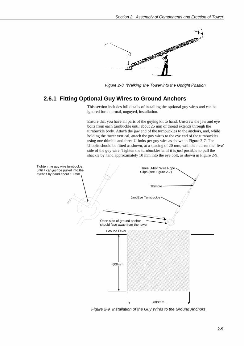
2.6 Tower Erection After all the appropriate sensors have been fitted, as outlined above, the tower can
be raised. Carefully ‘walk’ the tower (see Figure 2-8) to its upright position and fit
and tighten the two remaining bolts in the base assembly. Again, ensure that the
sensor wiring can reach the site of the enclosure, and that the high level sensors
appear to be in their correct orientations.
NOTE
NOTE
Take the guy wire (thimbles not required) around the tower structure and secure with three U-bolt wire clips, at 20 mm spacing, as shown
Standing side of guy wire
Section 2. Assembly of Components and Erection of Tower
2-9
Figure 2-8 ‘Walking’ the Tower into the Upright Position
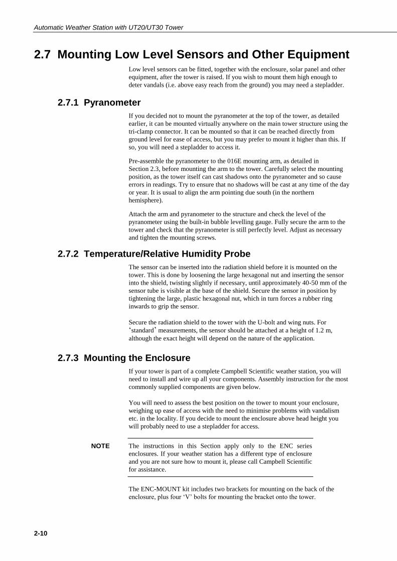
2.6.1 Fitting Optional Guy Wires to Ground Anchors
This section includes full details of installing the optional guy wires and can be
ignored for a normal, unguyed, installation.
Ensure that you have all parts of the guying kit to hand. Unscrew the jaw and eye
bolts from each turnbuckle until about 25 mm of thread extends through the
turnbuckle body. Attach the jaw end of the turnbuckles to the anchors, and, while
holding the tower vertical, attach the guy wires to the eye end of the turnbuckles
using one thimble and three U-bolts per guy wire as shown in Figure 2-7. The
U-bolts should be fitted as shown, at a spacing of 20 mm, with the nuts on the ‘live’
side of the guy wire. Tighten the turnbuckles until it is just possible to pull the
shackle by hand approximately 10 mm into the eye bolt, as shown in Figure 2-9.
Figure 2-9 Installation of the Guy Wires to the Ground Anchors
600mm
Three U-bolt Wire Rope Clips (see Figure 2-7)
Thimble
Jaw/Eye Turnbuckle
Open side of ground anchor should face away from the tower
Ground Level
Tighten the guy wire turnbuckle until it can just be pulled into the eyebolt by hand about 10 mm.
600mm
Automatic Weather Station with UT20/UT30 Tower
2-10
2.7 Mounting Low Level Sensors and Other Equipment Low level sensors can be fitted, together with the enclosure, solar panel and other
equipment, after the tower is raised. If you wish to mount them high enough to
deter vandals (i.e. above easy reach from the ground) you may need a stepladder.
2.7.1 Pyranometer
If you decided not to mount the pyranometer at the top of the tower, as detailed
earlier, it can be mounted virtually anywhere on the main tower structure using the
tri-clamp connector. It can be mounted so that it can be reached directly from
ground level for ease of access, but you may prefer to mount it higher than this. If
so, you will need a stepladder to access it.
Pre-assemble the pyranometer to the 016E mounting arm, as detailed in
Section 2.3, before mounting the arm to the tower. Carefully select the mounting
position, as the tower itself can cast shadows onto the pyranometer and so cause
errors in readings. Try to ensure that no shadows will be cast at any time of the day
or year. It is usual to align the arm pointing due south (in the northern
hemisphere).
Attach the arm and pyranometer to the structure and check the level of the
pyranometer using the built-in bubble levelling gauge. Fully secure the arm to the
tower and check that the pyranometer is still perfectly level. Adjust as necessary
and tighten the mounting screws.
2.7.2 Temperature/Relative Humidity Probe
The sensor can be inserted into the radiation shield before it is mounted on the
tower. This is done by loosening the large hexagonal nut and inserting the sensor
into the shield, twisting slightly if necessary, until approximately 40-50 mm of the
sensor tube is visible at the base of the shield. Secure the sensor in position by
tightening the large, plastic hexagonal nut, which in turn forces a rubber ring
inwards to grip the sensor.
Secure the radiation shield to the tower with the U-bolt and wing nuts. For
‘standard’ measurements, the sensor should be attached at a height of 1.2 m,
although the exact height will depend on the nature of the application.
2.7.3 Mounting the Enclosure
If your tower is part of a complete Campbell Scientific weather station, you will
need to install and wire up all your components. Assembly instruction for the most
commonly supplied components are given below.
You will need to assess the best position on the tower to mount your enclosure,
weighing up ease of access with the need to minimise problems with vandalism
etc. in the locality. If you decide to mount the enclosure above head height you
will probably need to use a stepladder for access.
The instructions in this Section apply only to the ENC series
enclosures. If your weather station has a different type of enclosure
and you are not sure how to mount it, please call Campbell Scientific
for assistance.
The ENC-MOUNT kit includes two brackets for mounting on the back of the
enclosure, plus four ‘V’ bolts for mounting the bracket onto the tower.
NOTE

Section 2. Assembly of Components and Erection of Tower
2-11
With the tower erected and levelled, mount the enclosure as follows:
1. Mount one bracket on the top two holes of the enclosure and the other on the
two bottom holes. The 8 mm bolts supplied are used to attach the brackets. Fit
the brackets with the ‘V’ cut-outs pointing away from the back of the
enclosure. See Figure 2-10, below.
Figure 2-10 Fitting the Enclosure
2. Offer up the enclosure to the tower uprights and present the ‘V’ bolts from the
other side of the tubing to fit into the two matching central holes of the
bracket.
3. Tighten the ‘V’ bolts up against the tower and brackets using the 6 mm nuts.
2.7.4 Mounting a Solar Panel
If you are using a solar panel with your weather station, you will need to consider
the most suitable position with regards to both operational and anti-vandalism
requirements.
Figure 2-11 Fitting the Solar Panel
Mounting Brackets
‘V’ cutout in bracket

Automatic Weather Station with UT20/UT30 Tower
2-12
Attach the solar panel to the tower and, for northern hemisphere applications,
orient it to face due south. For short-term applications the panel should be angled
approximately perpendicular to the solar angle at mid-day. For longer term
unattended applications such as a 12-month period, the solar panel should be
angled to obtain best performance during the winter months. This ‘optimum tilt
angle’ is equivalent to the latitude plus 15 degrees, facing permanently due south.
Ensure that the solar panel will not be cast into shadow at any time by other
equipment mounted on the tower.
2.8 Connections
2.8.1 Power Supply Connections
With the PS12E-LA / PS512-M Power Supplies
Route the cable from the solar panel (where fitted) into the enclosure via the cable
gland or connector (if ordered). Connect it to the charger circuit of the power
supply (see power supply manual).
With External Battery
Please refer to the solar panel manual for full details. Route the power cable from
the external battery into the datalogger enclosure and connect it directly to the
datalogger.
When connecting an SOP18 or a solar panel supplied with a separate regulator, make sure you observe the correct polarity when connecting to the battery. Incorrect connection can destroy the regulator.
2.8.2 Final Connections
1. Secure all grounding wire and sensor cables to the tower with cable ties.
2. Fit the sensor plugs into the sockets on the base of the enclosure following the
connection diagram supplied with each station.
3. Coil up any excess cable and strap it to the tower.
It is essential to secure excess cable to the tower as unsecured lengths of cable can blow around in the wind causing the wires to break inside, sometimes without any external signs of damage.
4. Make additional connections to and from the datalogger through the large
cable gland; any unused plugs or sockets should be sealed off using the
sealing caps. Tighten the cable gland and check that it seals properly.
CAUTION
CAUTION

Section 2. Assembly of Components and Erection of Tower
2-13
1. Cable glands will not seal directly onto most cables, especially
when more than one cable enters through a single gland. Please
refer to the Maintenance section for details.
2. The small cable gland on ENC series enclosures is for venting
purposes but may be used for additional cables if venting is not
needed. Please refer to the enclosure manual for further details.
5. Apply rustproofing compound as described in the Maintenance section.
2.9 Grounding and Lightning Protection Two different grounding kits can be supplied with the UT towers. Roof mount
towers are supplied with basic clamps to allow the enclosure and tower to be
bonded together. A separate clamp is provided for connection of the tower to the
building earth system – the cabling and wiring of which should be done by an
authorised electrician. A lightning spike is provided which should be fitted on the
top of the tower.
The grounding system for ground mounted towers consists of a lightning spike,
two copper-covered steel grounding spikes, grounding wire, clamps and
connectors. Install the grounding system as follows:
1. Screw the black Allen screw into the straight brass connector and then screw
the connector onto the blunt end of one of the copper-coated grounding
spikes. Drive the spike into the ground using the Allen screw as a driving
head. Position the spike as close as possible to the base of the tower.
2. Remove the Allen screw and screw the second spike into the straight
connector. Drive the second spike into the ground leaving about 100 mm
exposed above ground. This will drive the first spike to a depth of about 2.3 m
into the ground and should provide a good ground for lightning protection
purposes.
If the ground type does not permit you to drive the spikes in to a
total length of 2.3 metres then drive in the two rods individually,
spaced at least 2 metres apart, and join them together using a
length of the heavy gauge grounding wire, using additional clamps
(available from Campbell Scientific).
3. The lightning rod should already have been installed on the top of the tower as
shown in Section 2.2.
4. Connect the thicker grounding cable to the tower using the clamp provided
(the same type used to clamp the lightning spike to the top of the tower mast).
See Figure 2-12, below.
5. Connect the thinner grounding wire to the ground point on the underside of
the enclosure and tie it to the tower to reach the ground, also as shown in
Figure 2-12.
6. Connect both grounding cables to the exposed ground spike using the brass
grounding-bond clamp provided. If you had to install the spikes separately,
because of ground conditions, take the cable to the nearest spike. Try to keep
the length of wires used to a minimum, without coiling the wires. See
Figure 2-12.
NOTE
NOTE

Automatic Weather Station with UT20/UT30 Tower
2-14
7. Apply Waxoyl (or similar rustproofing compound) to the areas around the
lightning spike clamp, the grounding cable clamp and where the grounding
cable connects to the ground spike.
Figure 2-12 Grounding the Datalogger and the Tower
The grounding system supplied with the weather station
is designed to give the system protection against induced
transients and secondary lightning discharges. While the
system does offer some protection against lightning
damage, if the weather station is installed at a site where
frequent direct lightning strikes are likely, Campbell
Scientific recommends that you seek the advice of a
specialist lightning protection company.
2.10 Maintenance
2.10.1 Enclosure
1. Referring to the ENC 10/12, ENC12/14 and AM-ENC Enclosures Installation
Manual, seal the cable gland if it is used for cable entry.
Do not use bath or tile sealant, which gives off corrosive fumes that can damage circuit boards. Use proper electronic grade silicone rubber or plumber’s putty.
2. Place desiccant in the enclosure as described in the Enclosures Installation
Manual.
WARNING
CAUTION
Secondary (thinner) grounding wire
Grounding Clamp
Main grounding wire
Ground Spike
Tower Leg
Ground Rod Clamp

Section 2. Assembly of Components and Erection of Tower
2-15
Failure to use or exchange the desiccant may lead to condensation inside the enclosure. Not only will this lead to corrupted data, but, in the long term, can also cause corrosion which is expensive to repair.
If there will be an extended time between maintenance visits, we strongly recommend that extra desiccant packs are purchased and placed in the enclosure to ensure that it remains moisture free – see the Enclosures Installation.
2.10.2 Rust Prevention
Spray rustproofing compound over all bolts, joints and any exposed threads. Also
apply to any crevices where water may settle, especially around the eyebolts.
Exposed steel legs may be treated, but take care that any drainage channels from
the aluminium legs are not blocked.
This process must be repeated annually, if necessary repainting the steel base with
rust resistant paint.
Do not allow contact between rustproofing compound and the datalogger or sensors. In particular, avoid spraying the com-pound close to the humidity sensor.
Also ensure that water can drain effectively from the aluminium tubing of the tower to prevent water traps and possible damage from freezing. See Section 1.
2.10.3 Inspection
After a few days check that the tower is secure and level. Check the guy wires
(where fitted) and all bolts.
At least every year (and preferably every six months) check the tower, for tilting
and damage; check all guy wires (where fitted) and reapply rustproofing
compound as before, especially around the eyebolts.
The desiccant pack in the enclosure should be changed or dried out at an interval
which depends on how frequently the enclosure door is opened. Drying may be
done by placing in an oven at 120°C for 16 hours. In general the desiccant will last
as long as a set of alkaline batteries (4-6 months) if the door is opened for a few
minutes each week. More frequent inspections of the datalogger or operation in
very wet or humid conditions may require more frequent changing of desiccant. A
mineral desiccant is recommended and can be supplied upon request.
2.10.4 Sensors
Please refer to individual sensor manuals for maintenance and calibration
procedures.
High-Level Sensors
To thoroughly check and maintain sensors mounted at a high level, you will have
to tilt the tower to the ground to access the sensors. This is done as follows:
1. Loosen the turnbuckle on the guy wire (where fitted) at the rear of the tower
(i.e. in the direction of tilt), and slip the guy wire from the anchor bolt.
2. Remove both the bolts holding the rear leg into the base section.
CAUTION
CAUTION
Automatic Weather Station with UT20/UT30 Tower
2-16
3. Remove the lower bolts in the other two legs, and loosen the upper bolts in
these legs just enough to allow the tower to be tilted when a small amount of
force is applied.
4. Gently lower the tower to the ground, supporting and packing the structure as
necessary to avoid damage to the sensors or other delicate equipment.
When the tower is safely on the ground you can check and maintain the sensors or
any other equipment as required. If re-alignment of sensors is necessary, you may
have to remove the top section of the mast and proceed as outlined in Section 2.3
of this manual.
After all necessary maintenance has been carried out, re-erect the tower following
the procedures given in Section 2.6. Re-check all three guy wires for security and
carry out any other maintenance such as rust prevention as detailed above.
Low-Level Sensors and equipment
If you have lowered the tower for maintenance of the high-level sensors as detailed
above, you may wish to check all other equipment at the same time.
Alternatively sensors and the enclosure etc. which are mounted at a lower level,
but which may be above head height, can be maintained by using a suitable
stepladder.
3-1
Section 3. Programming This section describes how to program your AWS, either by using Campbell Scientific’s
`point-and-click’ program building software Short Cut (part of PC200W), or, for more
experienced programmers, by using Edlog or the CRBasic Editor, part of the more advanced
Datalogger Support packages, PC400 or LoggerNet.
3.1 Introduction Your standard AWS will normally be programmed using Short Cut, an easy to use
program builder, which is part of Campbell Scientific’s datalogger support
software package, PC200W. Short Cut covers all of the standard sensors and
produces a wiring diagram which should always be used when wiring up your
sensors and peripherals. The use of Short Cut and the PC200W software is fully
explained in the PC200W User Guide.
If you are a more experienced datalogger programmer, and the programs provided
by Short Cut do not fully meet your needs, for example if you wish to use a `non-
standard’ sensor, then you can write or edit your own programs using the Edlog or
the CRBasic program editor which is part of the optional PC400 and LoggerNet
datalogger support software packages. The new or edited program can then be
downloaded to the datalogger as described below.
3.1.1 Programming
After installing the software as described in the User Guide, use the datalogger
program as follows:
1. Set up the link between your PC and the datalogger. The simplest method is a
direct link using the SC32B opto-isolated interface or an SC929 Interface
Cable. Refer to the manuals for the interface you are using for connection
details. No separate interface is required for the CR23X, CR3000 or CR1000.
If you intend to use a different link (such as a telephone or short-haul modem)
consult the instruction manuals for the appropriate device.
2. Turn on the datalogger. For a datalogger with the PS100E power supply,
connect the power using the in-line connector between the power supply and
the datalogger. (The lead-acid battery in a PS100E-LA is also shipped
disconnected and should be plugged into the charger circuit.)
The PS100E-LA supply has a power switch under the battery cover.
After turning the datalogger on, leave it for at least one minute to complete its
power-up tests (see datalogger manual for details of power-up sequence).
3. Use the communications setup in PC200W/PC400/LoggerNet to call the AWS
as described in the appropriate software manual.
4. Also use the appropriate function of PC200W, PC400 or LoggerNet to
download the datalogger program you created earlier to the AWS.
5. Use the other functions of the software as required. For example, you can set
the datalogger clock and monitor the sensor readings to verify that the sensors
have been installed correctly. See the appropriate software manual for details.

Automatic Weather Station with UT20/UT30 Tower
3-2
6. If you want to amend or edit the program use Short Cut, CRBasic or Edlog as
appropriate.
Full details of all the functions of PC200W/PC400 or LoggerNet are
contained in the User Guide for the software.
Campbell Scientific dataloggers can be programmed from a
computer without using the datalogger support software by using
telecommunications commands. However, this is not normally
necessary and is not recommended as a general method of
datalogger programming.
NOTE

A-1
Appendix A. Using True North for
Accurate Wind Measurements
To get optimum wind direction data from your weather station, it is recommended that you
set up your wind direction sensor with reference to true north (rather than magnetic north).
This Appendix provides some additional information about using true north.
A.1 Magnetic Declination Magnetic declination is sometimes referred to as the magnetic variation or the
magnetic compass correction. It is the angle formed between true north and the
projection of the magnetic field vector on the horizontal plane. Magnetic
declination varies according to geographical location. In the UK, for instance, it
changes by over eight degrees from the most Easterly to the most Westerly points.
Also, the magnetic pole tends to wander or drift, so its location can change over
time. Therefore it is recommended that wind direction measurements are made
with reference to true north.
A.2 Determining True North The difference between true and magnetic north is easily corrected by adding or
subtracting the difference between the two readings as explained below. Maps are
always drawn in relation to the true north pole, and ordnance survey maps will
normally show the offset or declination angle between true and magnetic north.
To find true north bearing for a specific site do the following:
1. First establish the declination angle (or offset) between magnetic and true
north, usually from an ordnance survey map, as described above.
2. Establish the position of magnetic north accurately, using a good quality
compass.
3. Add (or subtract) the declination angle to find the position of true north for
your site. (In the UK the declination angle from magnetic to true north will
always be to the east, and so will be added to the magnetic north value, as
shown in Figure A-1, below.)
Figure A-1 Declination Angles – True North to East of Magnetic North
Declination angles for True North to the East of
Magnetic North are added to 0, therefore True
North reading is (0+15 = ) 15 for this specific case.
MAGNETIC NORTH
NEEDLE POINTS TO MAGNETIC NORTH
TRUE NORTH (map bearing) 15 EAST OF MAGNETIC NORTH
Point the wind direction sensor
to TRUE NORTH (15) bearing.

Automatic Weather Station with UT20/UT30 Tower
A-2
Figure A-2 Declination Angles – True North to West of Magnetic North
For UT920/UT930-based weather stations, firstly determine the
declination angle. Use this value in conjunction with the magnetic
north bearing to set the wind sensor to true north as explained in
Section 2.3 of this manual.
NOTE
Declination angles for True North to the West of
Magnetic North are subtracted from 360, therefore
True North reading is (360– 15 = ) 345 for this specific case.
MAGNETIC NORTH
COMPASS NEEDLE POINTS TO MAGNETIC NORTH
TRUE NORTH (map bearing) 15 WEST OF MAGNETIC NORTH
Point the wind direction sensor to
TRUE NORTH (345) bearing.


CAMPBELL SCIENTIFIC COMPANIES
Campbell Scientific, Inc. (CSI)
815 West 1800 North Logan, Utah 84321 UNITED STATES
www.campbellsci.com [email protected]
Campbell Scientific Africa Pty. Ltd. (CSAf) PO Box 2450
Somerset West 7129 SOUTH AFRICA
www.csafrica.co.za [email protected]
Campbell Scientific Southeast Asia Co., Ltd. 877/22 Nirvana@Work, Rama 9 Road
Suan Luang Subdistrict, Suan Luang District Bangkok 10250
THAILAND www.campbellsci.asia [email protected]
Campbell Scientific Australia Pty. Ltd. (CSA) PO Box 8108
Garbutt Post Shop QLD 4814 AUSTRALIA
www.campbellsci.com.au [email protected]
Campbell Scientific do Brazil Ltda. (CSB) Rua Apinagés, nbr. 2018 - Perdizes
CEP: 01258-00 São Paulo SP BRAZIL www.campbellsci.com.br [email protected]
Campbell Scientific Canada Corp. (CSC) 14532 – 131 Avenue NW
Edmonton, Alberta T5L 4X4 CANADA
www.campbellsci.ca [email protected]
Campbell Scientific Centro Caribe S.A. (CSCC) 300N Cementerio, Edificio Breller
Santo Domingo, Heredia 40305 COSTA RICA
www.campbellsci.cc [email protected]
Campbell Scientific Ltd. (CSL) 80 Hathern Road, Shepshed, Loughborough LE12 9GX
UNITED KINGDOM www.campbellsci.co.uk [email protected]
Campbell Scientific Ltd. (France) 3 Avenue de la Division Leclerc
92160 ANTONY FRANCE
www.campbellsci.fr [email protected]
Campbell Scientific Spain, S. L. Avda. Pompeu Fabra 7-9
Local 1 - 08024 BARCELONA SPAIN
www.campbellsci.es [email protected]
Campbell Scientific Ltd. (Germany) Fahrenheitstrasse13, D-28359 Bremen
GERMANY www.campbellsci.de [email protected]
Campbell Scientific (Beijing) Co., Ltd. 8B16, Floor 8 Tower B, Hanwei Plaza
7 Guanghua Road, Chaoyang, Beijing 100004 P.R. CHINA
www.campbellsci.com [email protected]
Please visit www.campbellsci.eu to obtain contact information for your local EU or International representative.


