
Manual No.: 14947001
Date of Release 15.11.2012
Accutom-5Instruction Manual

Accutom-5 Instruction Manual
Table of Contents Page User’s Guide ............................................................... 1Reference Guide ....................................................... 25Quick Reference Guide ............................................ 47
Always state Serial No and Voltage/frequency if you have technical questions or when ordering spare parts. You will find the Serial No. and Voltage on the type plate of the machine itself. We may also need the Date and Article No of the manual. This information is found on the front cover. The following restrictions should be observed, as violation of the restrictions may cause cancellation of Struers legal obligations: Instruction Manuals: Struers Instruction Manual may only be used in connection with Struers equipment covered by the Instruction Manual. Service Manuals: Struers Service Manual may only be used by a trained technician authorised by Struers. The Service Manual may only be used in connection with Struers equipment covered by the Service Manual. Struers assumes no responsibility for errors in the manual text/illustrations. The information in this manual is subject to changes without notice. The manual may mention accessories or parts not included in the present version of the equipment. Original instructions. The contents of this manual is the property of Struers. Reproduction of any part of this manual without the written permission of Struers is not allowed. All rights reserved. © Struers 2012. Struers A/S Pederstrupvej 84 DK-2750 Ballerup Telephone +45 44 600 800 Fax +45 44 600 801

Accutom-5 Instruction Manual
Accutom-5 Safety Precaution Sheet
To be read carefully before use 1. The operator should be fully instructed in the use of the machine and its
cut-off wheels according to the Instruction Manual and the instructions for the cut-off wheels.
2. The machine must be placed on a safe and stable support table.
3. Be sure that the actual voltage corresponds to the voltage stated on the back of the machine. The machine must be earthed.
4. Use only intact cut-off wheels. The cut-off wheels must be approved for min. 3000 rpm. If other cut-off wheels or saw blades are used, make sure that the speed setting of Accutom-5 complies with the max. speed for the cut-off wheels or saw blades.
5. Observe the current safety regulations for handling, mixing, filling, emptying and disposal of the additive for cooling fluid.
6. The sample must be securely fixed in the specimen holder.
7. Do not touch the sample, the specimen holder head or the cut-off wheel while positioning the sample with the POSITION controls.
8. Never try to open the cover before the cut-off wheel has stopped completely.
The equipment should only be used for its intended purpose and as detailed in the Instruction Manual. The equipment is designed for use with consumables supplied by Struers. If subjected to misuse, improper installation, alteration, neglect, accident or improper repair, Struers will accept no responsibility for damage(s) to the user or the equipment. Dismantling of any part of the equipment, during service or repair, should always be performed by a qualified technician (electromechanical, electronic, mechanical, pneumatic, etc.).

Accutom-5 Instruction Manual
Disposal Equipment marked with a WEEE symbol contain electrical and electronic components and must not be disposed of as general waste. Please contact your local authorities for information on the correct method of disposal in accordance with national legislation.

Accutom-5 Instruction Manual
1
User’s Guide Table of Contents Page
1. Getting Started 3Checking the Contents of Packing ..................................................... 3Placing Accutom-5 ............................................................................. 3Getting Acquainted with Accutom-5 ................................................... 3Supplying Power ................................................................................ 4
Changing the voltage setting .................................................... 4Recirculation Unit ............................................................................... 6Software Settings ............................................................................... 7
Configuration Menu ................................................................... 7Setting the Language ................................................................ 8
2. Basic Operations 9Using the Controls .............................................................................. 9
Front Panel Controls of Accutom-5 ........................................... 9Groups of Keys ......................................................................... 9Acoustic Signals ........................................................................ 9Location of Main Switch ............................................................ 9
Front Panel Controls ........................................................................ 10Display .................................................................................... 11
Reading the Display ......................................................................... 12Changing/Editing Values .................................................................. 13
Numeric Values ....................................................................... 13Alphanumeric Values .............................................................. 14
Positioning the Sample .................................................................... 15Reference Position .................................................................. 15Absolute Position .................................................................... 15Relative Position ..................................................................... 15Relative Zero ........................................................................... 15Stop Position ........................................................................... 15
Cutting .............................................................................................. 16Changing the Cut-off Wheel .................................................... 16Clamping the Sample and Specimen Holder .......................... 17Positioning the Sample ........................................................... 17
Setting the Cutting Parameters ........................................................ 18Wheel ...................................................................................... 18Speed ...................................................................................... 18Feed ........................................................................................ 18Force ....................................................................................... 18Rotation ................................................................................... 19Water ...................................................................................... 19

Accutom-5 Instruction Manual
2
Starting the Cutting .......................................................................... 19 During Cutting .................................................................................. 20
Changing the Feed Speed ...................................................... 20Retracting the Sample ............................................................ 20Force Limit Reached ............................................................... 20
Stopping the Cutting ......................................................................... 21Automatic Stop ........................................................................ 21Manual Stop ............................................................................ 21
3. Maintenance Daily Service .................................................................................... 22
Checking the Recirculation Unit .............................................. 22Weekly Service ................................................................................ 23Refilling the Cooling Water Tank ...................................................... 23
Emptying and Cleaning the Tank ............................................ 23Refilling the Tank .................................................................... 23
Maintenance of Cut-off Wheels ........................................................ 24Maintenance of Diamond and CBN Cut-off Wheels ................ 24Storing of Abrasive Cut-off Wheels ......................................... 24

Accutom-5 Instruction Manual
3
1. Getting Started In the packing box you should find the following parts: 1 Accutom-5 2 Mains cables 1 Specimen Holder with parallel vice 1 Flange for cut-off wheels (42 mm dia.) 1 Stop pin 1 Spanner, 17mm 1 Small grate 1 Large grate 1 Allen key, 2 mm 1 Allen key, 2.5 mm 1 Allen key, 3 mm 1 Allen key, 4 mm 1 Allen key 5 mm 2 Screws M4x20 2 Screws M4x35 1 Set of Instruction Manuals Accutom-5 should be placed on a stable and plane (tolerance ±1 mm) table. The table must be able to carry a weight of min. 50 kg. Take a moment to familiarise yourself with the location and names of the Accutom-5 components.
A Front panel/Front panel control(s) B Main switch C Recirculation Cooling Unit D Cut-off wheel E Specimen holder head
Checking the Contents of Packing
Placing Accutom-5
Getting Acquainted with Accutom-5

Accutom-5 Instruction Manual
4
Always remember to switch the power off when installing electrical equipment!
The factory setting for Accutom-5 is 240V.
Pull out the fuse holder from the cable terminal at the back of the
machine. Pull out the voltage switch and turn it to the correct setting.
Voltage Required Setting 230 or 240V 240V 200 to 220V 200V
Note: The two additional settings, 110V and 120V are not to be used.
Reinsert the voltage switch. Put the fuse holder back into the cable terminal.
Supplying Power
DANGER!
The machine must be earthed
IMPORTANT Check that the mains voltage corresponds to the voltage stated
on the type plate on the back of the machine.
Changing the voltage setting
If the factory setting is not the correct setting for your mains supply the setting can be changed from 240V to 220V:

Accutom-5 Instruction Manual
5
Accutom-5 is shipped with 2 types of Mains cables: The 2-pin (European Schuko) plug is for use on single-phase connections. If the plug supplied on this cable is not approved in your country, then the plug must be replaced with an approved plug. The leads must be connected as follows: Yellow/green: earth Brown: line (live) Blue: neutral The 3-pin (North American NEMA) plug is for use on 3-phase power connections. If the plug supplied on this cable is not approved in your country, then the plug must be replaced with an approved plug. The leads must be connected as follows: Green: earth Black: line (live) White: line (live) Both cables are on the other end equipped with an IEC 320 cable connector that has to be connected to the Accutom.
Single-phase Supply
3-phase Supply
Connection to the Machine
WARNING! The output voltage from this cable is 200 – 240V and not 110V.
DO NOT use this cable to connect equipment that use a 110V power supply. Failure to adhere to this may result in material damage.

Accutom-5 Instruction Manual
6
Pull out the recirculation tank. Fill the tank with 3.88 l water and 120 ml Struers Additive for
cooling fluid. The water level should be 5 mm below the edge of the front hole in the tank cover.
Check that the cover is fitted securely into place in the
recirculation tank and push the drawer with the recirculation tank into place again.
Check that the end of the inlet tube has dropped into position.
Recirculation Unit
IMPORTANT Always ensure that there is sufficient water in the tank as the recirculation
pump will be damaged if it is run dry.
Note: Changing of cooling water should be done at least once a month.
IMPORTANT Always maintain the correct concentration of Struers Additive in the cooling water (percentage stated on the container of the Additive). Remember to
add Struers Additive for cooling fluid each time you refill with water. Do not use any oil, petrol, or turpentine-based additives, only Struers
additive.

Accutom-5 Instruction Manual
7
Switch on the power at the main switch located at the back of the machine. The following display will appear briefly:
Afterwards the display will change to the same screen which was shown before Accutom-5 was switched off, usually a cutting method. When switching Accutom-5 on for the first time, the display to appear should be the MAIN MENU. If the heading in the display is different, press Esc, until the MAIN MENU appears. (A long beep can be heard). The MAIN MENU is the highest level in the menu structure. From here you can go to configuration, manual functions and cutting methods.
MAIN MENU CUTTING METHODS MANUAL FUNCTIONS CONFIGURATION
Press MENU UP/DOWN
to select CONFIGURATION.
Press ENTER to activate the CONFIGURATION menu.
CONFIGURATION CUT-OFF WHEELS OPTIONS
Software Settings Configuration Menu

Accutom-5 Instruction Manual
8
Press MENU UP/DOWN
to select OPTIONS.
CONFIGURATION
CUT-OFF WHEELS OPTIONS
Press ENTER to activate the OPTIONS menu.
OPTIONS Language : ENGLISH X-retract Contrast : 40
: OFF
F1: DEFAULT VALUE
Press ENTER to activate the LANGUAGE Menu.
LANGUAGE
ENGLISH DEUTSCH FRANÇAIS ESPAÑOL
Press MENU UP/DOWN
to select the Language you prefer.
Press ENTER
to accept the language. The OPTIONS Menu now appears in the language you have chosen.
Setting the Language

Accutom-5 Instruction Manual
9
2. Basic Operations
A Programming and monitoring functions B Positioning of the specimen holder C Start/stop of Accutom-5 Short Beep: when a key is pressed, a short beep indicates that
the command has been accepted. Long Beep: a long beep indicates that the key is inactive at that
moment. The main switch is located on the back of the machine.
Using the Controls Front Panel Controls of Accutom-5
Groups of Keys
Acoustic Signals
Location of Main Switch
Please Note... The contents of the program memory are not lost when the main switch is
turned off.

Accutom-5 Instruction Manual
10
Name Key Function Name Key Function
MAIN SWITCH
The main switch is located on the back of the machine.
ESC
Esc Leaves the present menu or specimen holder position screen.
START
Starts the cutting process according to the pre-set method. The recirculation water, if selected, is turned on.
FAST POSITION LEFT
Changes to POSITION menu or moves the specimen holder to the left in the X-direction in steps of 100 µm. Keep the key pressed to increase the speed.
STOP
Stops the cutting process. The recirculation water, if selected, is turned off.
FAST POSITION RIGHT
Changes to POSITION menu or moves the specimen holder to the right in the X-direction in steps of 100 µm. Keep the key pressed to increase the speed.
FUNCTION KEYS
F1/F2 F3/F4
Controls for various purposes. See the bottom of the individual screens.
POSITION LEFT
Changes to POSITION menu or moves the specimen holder slowly to the left in the X-direction in steps of 5 µm. Keep the key pressed to increase the speed.
MENU
Scrolls up () or down () in the menu tree structure of Accutom-5. When setting a parameter the value is increased () or decreased (
).
POSITION RIGHT
Changes to POSITION menu or moves the specimen holder slowly to the right in the X-direction in steps of 5 µm. Keep the key pressed to increase the speed.
ENTER
Selects a marked parameter value or chooses a menu.
POSITION UP/DOWN /
Changes to POSITION menu or moves the specimen holder up- or downwards in the Y-direction in steps of 100 µm. Keep the key pressed to increase the speed.
Front Panel Controls

Accutom-5 Instruction Manual
11
SELECT CUTTING METHOD 1.EMPTY METHOD 2.EMPTY METHOD
3.EMPTY METHOD 4.EMPTY METHOD 5.EMPTY METHOD 6.EMPTY METHOD 7.EMPTY METHOD 8.EMPTY METHOD 9.EMPTY METHOD 10.EMPTY METHOD 11.EMPTY METHOD 12.EMPTY METHOD
A Heading B Inverted text. Cursor C Function key options D Arrow indicates, that there are more lines in the picture
Display
Please Note The examples of display screens in this Instruction Manual show a number of possible texts. The actual display screen may differ from the examples in
the Instruction Manual.
B
C
A D

Accutom-5 Instruction Manual
12
The display can show various kinds of information, for example about the cutting method or about the sample position. A screen for a cutting method could look as the following example: Cutting Method: 1. EMPTY METHOD Wheel :B0D15 Speed : 2700 rpm Feed :0.100 mm/s Force : MEDIUM Rotation: OFF Water : ON
Pressing one of the X-axis positioning keys will change the screen to the following:
X-POSITIONS
Absolute Position: 15.255 mm Relative Position: 5.000 mm F1:RESET F2:ADD F3:MOVE TO REL. ZERO
Pressing one of the Y-axis positioning keys will change the screen to the following:
Y-POSITIONS Absolute Position: 55.7 mm Relative Position: 0.0 mm Stop Position: 20.0 mm F1:RESET F2:SET STOP F3:MOVE TO REL.ZERO
Esc Press Esc, to return to the cutting method screen.
Reading the Display
The “heavy” arrows on the display indicate the direction in which the sample holder is moved, for example:
X-POSITIONS
Y-POSITIONS

Accutom-5 Instruction Manual
13
Depending on the type of value, there are two different ways of editing. Cutting Method: 1. EMPTY METHOD Wheel : B0D15 Speed : 2700 rpm Feed :0.100 mm/s Force : MEDIUM Rotation: OFF Water : ON
Press MENU UP/DOWN
to select the numeric value you want to change, e.g. Feed:
Cutting Method: 1. EMPTY METHOD Wheel : B0D15 Speed : 2700 rpm Feed :0.100 mm/s Force : MEDIUM Rotation: OFF Water : ON
Press ENTER
, to edit the value.
Two square brackets [ ] appear around the value. Cutting Method: 1. EMPTY METHOD Wheel : B0D15 Speed : 2700 rpm Feed [0.100]mm/s Force : MEDIUM Rotation: OFF Water : ON
Press MENU UP/DOWN
to increase or decrease the numeric value.
Press ENTER
, to accept the new value.
or Esc Press Esc, to keep the original value.
Changing/Editing Values
Numeric Values

Accutom-5 Instruction Manual
14
Cutting Method: 1. EMPTY METHOD Wheel : B0D15 Speed : 2700 rpm Feed :0.100 mm/s Force : MEDIUM Rotation: OFF Water : ON
Press MENU UP/DOWN
to select the alphanumeric value you want to change, e.g. Cut-off wheel:
Press ENTER
, to edit the value.
A submenu appears.
CUT-OFF WHEELS M0D08 M1D08 M0D10 M1D10 M0D13 M1D13 B0D13 B0C13 50A13 30A13 SAW13 M0D15 M1D15 E0D15 B0D15 B0C15 50A15 40A15 10S15 30A15 USER 1 USER 2 USER 3 USER 4 USER 5 USER 6 USER 7 USER 8 USER 9 USER10
Press MENU UP/DOWN
to select the correct cut-off wheel.
Press ENTER
, to accept the new value and to return to the previous screen.
or
Esc Press Esc, to keep the original value and to return to the previous screen.
Alphanumeric Values

Accutom-5 Instruction Manual
15
After clamping the sample in the specimen holder, the holder is placed in the specimen holder head and fixed there. To move the specimen holder and the sample, the POSITION keys are used. The display shows the position in either X- or Y- direction. Every time the power is switched on while the cover is closed, Accutom-5 checks its own reference position. The sample holder head will be moved back as far as possible, to the reference position (X=0.000 Y=0.0), and thereafter it will return to the position where it was before the power was switched on. The absolute position shows the total distance the specimen holder has travelled from the reference position. The relative position equals that of the absolute position until it is set to zero at a desired point. By setting it to zero, calculation of the sample movement close to the cut-off wheel is made easier. The screen value always relates to the distance the specimen holder has travelled since being set to zero. The relative zero position is the point where the relative position in either the X- or Y- position was set to zero. Having completed the cutting process, the sample holder automatically returns to this point. Pressing F3 when in the X-or Y- position screen also returns the sample to the relative zero position. A stop position can be set to halt the cutting process at a precise point. After reaching this point the sample will be retracted and returned to the relative zero position. Please make sure when setting the stop position to compensate for possible wear of the cut-off wheel. This is especially important when using Al2O3
or SiC wheels.
Positioning the Sample
Reference Position
Absolute Position
Relative Position
Relative Zero
Stop Position
Compensating for Wheel Wear

Accutom-5 Instruction Manual
16
Open the cover and swing the right cooling tube in the air. Insert the stop pin in the hole of the inner flange. Use the spanner (17 mm) to loosen the flange screw. Remove the outer flange and the wheel.
Mount the new cut-off wheel and remount the outer flange, with
the machined face towards the inner flange. Insert the locking pin in the hole in the inner flange. Fasten the flange screw gently using the spanner. Swing the right cooling tube back in its place.
Cutting Changing the Cut-off Wheel
IMPORTANT The tolerance between the spindle and inner flange is very small which
means that the two surfaces must be absolutely clean. Never try to squeeze the cut-off wheel on as this may damage the spindle. If there are any small
burrs remove them with grinding paper (grit size 1200). Socket Spanner
Stop Pin
Cooling Tube with Plug

Accutom-5 Instruction Manual
17
Clamp the sample securely in the specimen holder using the appropriate Allen key.
Fasten the specimen holder in the specimen holder head by pushing the specimen holder into the dovetail fixture and tightening the screw with an Allen key.
When cutting with rotation or oscillation, the sample and the specimen holder should be clamped so that they rotate evenly around the centre of the sample. This way the fastest cutting is obtained as the cut-off wheel will be cutting most of the time and the possibility of damaging the cut-off wheel is limited.
Move the sample into the correct start position, close to the cut-
off wheel by using the POSITION keys. Reset the relative position in both X- and Y-direction by pressing
F1 when in the respective screens. Set the stop position to define the length of the cut: There are two ways of setting the stop position: 1. If you know the size of your sample:
− Press ENTER and use MENU UP/DOWN
− Press ENTER again to accept the value or Esc to cancel.
to set the stop value.
2. If you do not know the exact size of your sample:
− Position the sample using the POSITION key so you can move it along the cut-off wheel.
− Move the sample along the cut-off wheel to the required stop position using the POSITION key .
− Press F2:SET STOP to record the stop position. − Press F3:MOVE TO REL.ZERO to move the sample back
into the initial position. − Position the sample correctly in front of the cut-off wheel
using the POSITION key . If possible use F3:MOVE TO REL.ZERO.
Clamping the Sample and Specimen Holder
Positioning the Sample

Accutom-5 Instruction Manual
18
All cutting parameters can be edited independently of each other. See section Changing/Editing values for details on how to change values. Cutting Method: 1. EMPTY METHOD Wheel : B0D15 Speed : 2700 rpm Feed :0.100 mm/s Force : MEDIUM Rotation: CONT. Speed: 1 Dir.: > < Water : ON F3:TEST ROTATION F4:SAVE All Struers cut-off wheels are listed with their default values for force limit, wheel thickness and speed. Also eight undefined wheels are included for your own choice of cut-off wheels. (See also configuration of cut-off wheels). The speed of the cut-off wheel can be set between 300 and 3000 rpm in steps of 100 rpm. The default values for all Struers cut-off wheels are already saved together with the wheel definitions. Whenever a different cut-off wheel is selected the recommended speed will automatically be inserted. The feed speed can be set between 0.005 mm/s and 3.000 mm/s. (See the section Cutting Parameters in chapter 3. Consumables for recommended settings). The force limit is a protection for the cut-off wheel and/or the samples to be cut. Depending on the thickness or strength of the cut-off wheels the force limit can be set to three different levels, LOW, MEDIUM and HIGH. The default values for all Struers cut-off wheels are already saved together with the wheel definitions. Whenever a different cut-off wheel is selected, the recommended force limit will automatically be inserted. Sample rotation can be an advantage when cutting large, very hard, coated or very long samples. On Accutom-5, three different settings are possible.
Setting the Cutting Parameters
Method Screen
Wheel
Speed
Feed
Force

Accutom-5 Instruction Manual
19
The sample does not rotate. The sample is rotating around its centre. The speed can be set to three different levels, 1, 2 or 3. The direction of rotation can be set to either counter- or co-rotation. Counter-rotation is recommended. Press F3 to test sample rotation with the set parameters. The sample is rocking/oscillating around its centre. The speed can be set to three different levels, 1, 2 or 3. The angle can be adjusted from 10° to 400°. Press F3 to test sample rotation with the set parameters.
The cooling water can be set to either on or off. For all normal cutting operations the setting should be on. Before you start cutting make sure that the cutting chamber is clean to ensure a free flow of cooling water. Position the sample correctly. Set the correct cutting parameters. Make sure that the correct cut-off wheel is mounted. Close the cover of the machine. Press START
.
Rotation Only for Accutom-5 with rotation Rotation: Off
Rotation: Continuous
Rotation: Oscillating
Note When the sample is moved in the x- or y- direction, with Rotation set to
Cont. or Osc. a warning message, “Rotation Mode !”, will briefly flash on the screen as a reminder that rotation mode is selected.
Water
Starting the Cutting
Co-rotation Counter-rotation

Accutom-5 Instruction Manual
20
After Start has been pressed, the display changes to the following: Feed Speed CUTTING STARTED 0% 100% Pre-set Feed Speed : 0.100 mm/s Actual Feed Speed : 0.100 mm/s Remaining Process Time: 3 min Both the pre-set and the actual feed speed are displayed. The horizontal bar is used to display the feed speed graphically. During the cutting process the feed speed can be changed. Simply press Enter and change the feed speed to the correct value. Press Enter again to confirm the change or Esc to cancel. The only possibility of moving the sample after the cutting process has been started is to retract the sample from the cut-off wheel. This can be done by pressing the POSITION DOWN key. The forward movement of the sample is stopped and the sample moved backwards until the key is released again. Then the sample will start again to move forward with the pre-set feed speed. If the pre-set feed speed can not be achieved because the force limit is reached, Accutom-5 automatically reduces the feed speed to the maximum possible speed. This value is displayed, and after the cut is finished, the following message is shown on the display:
CUTTING FINISHED
Force limit was reached during cutting feed speed reduced to:
0.070 mm/sec
For similar samples to be cut afterwards, the feed speed should be reduced to the new value or below.
During Cutting
Changing the Feed Speed
Retracting the Sample
Force Limit Reached

Accutom-5 Instruction Manual
21
Accutom-5 automatically stops the cutting process at the pre-set stop position. (Make sure to compensate for possible wheel wear when setting the stop position).
The sample is then retracted and the cut-off wheel is stopped. The cutting process can be stopped at any time during operation
by pressing the STOP
To avoid stopping the process while the cut-off wheel still is in the sample, press the POSITION key for the Y-direction and then press F2:SET STOP. The sample is retracted immediately and the process will be stopped when the relative zero position is reached.
key. The sample remains in its actual position and the process stops there.
The display changes back to what it was before cutting was started.
Stopping the Cutting Automatic Stop
Manual Stop
Accutom-5 Instruction Manual
22
3. Maintenance Clean the cutting chamber with a damp cloth. Do not use tap
water as you risk overflow in the recirculation cooling water tank. Remember to remove all dirt particles from the grate.
Clean the specimen holder head and the clamps for the dovetail feed.
Clean the flanges. Clean the transparent cover with a damp cloth.
The cooling unit should be checked for cooling water after 8 hours use or at least every week. Refill the cooling unit if the flushing pump cannot reach the cooling water. Remember to add Struers Additive for Cooling Fluid: One part of Additive for 33 parts of water. Use a refractometer to check the concentration of additive. Concentration = Brix value. The concentration of additive should lie between 2.7 and 3.3 %. Add Struers Additive for Cooling Fluid if the concentration is too low.
Daily Service
WARNING! Do not use alcohol, acetone or similar solvents.
Checking the Recirculation Unit
IMPORTANT Always maintain the correct concentration of Struers Additive in the cooling water (percentage stated on the container of the Additive). Remember to
add Struers Additive each time you refill with water.

Accutom-5 Instruction Manual
23
Clean the specimen holder(s): movable parts, dovetail feeds and screws. Lubricate with acid free oil.
Clean the cutting chamber and cover thoroughly. Remember to remove all dirt particles from the grate.
Replace the cooling water in the Recirculation Cooling Unit at least once a month. Carefully pull out the drawer and lower the hinged front plate. Carefully pull out the flat tank. Remove the cover plate and empty the tank into a drain
approved for waste chemicals. Clean the tank, the dividers and the cover with tap water. Place the dividers correctly in the tank and replace the cover
plate. Press the cover plate into the tank and make sure it is seated
firmly.
Fill the tank with 3.88 l water and 120 ml Struers Additive. The
water level should be 5 mm below the edge of the front hole in the tank cover.
Push the drawer with the recirculation tank back into place.
Weekly Service
Refilling the Cooling Water Tank Emptying and Cleaning the Tank
IMPORTANT The container and the cover plate have to be placed correctly, otherwise the
pump cannot suck up the water.
IMPORTANT Flush the recirculation system with clean water if Accutom is not to be used
over longer periods of time. This will prevent any dried residue of cutting material from damaging the inside of the pump.
Refilling the Tank
IMPORTANT Always ensure that there is sufficient water in the tank as the recirculation
pump will be damaged if it is run dry.
IMPORTANT Always maintain the correct concentration of Struers Additive in the cooling water (percentage stated on the container of the Additive). Remember to
add Struers Additive each time you refill with water.

Accutom-5 Instruction Manual
24
The precision of diamond and CBN cut-off wheels and thus the cut depends on how carefully the following instructions are observed: Never expose the cut-off wheel to overload, such as heavy
mechanical load, or heat. Store the cut-off wheel in a dry place, horizontally on a plane
support, preferably under light pressure. A clean and dry cut-off wheel does not corrode. Therefore, clean
and dry the cut-off wheel before storing. If possible, use ordinary detergents for the cleaning.
Regular dressing of the cut-off wheel is also part of the general maintenance (see ADVANCED OPERATIONS).
These cut-off wheels are sensitive to humidity. Therefore, do not mix new, dry cut-off wheels and used, humid ones. Store the cut-off wheels in a dry place, horizontally on a plane support.
Maintenance of Cut-off Wheels Maintenance of Diamond and CBN Cut-off Wheels
Storing of Abrasive Cut-off Wheels

Accutom-5 Instruction Manual
25
Reference Guide Table of Contents Page
1. Advanced Operations Configuration Menu .......................................................................... 26
Cut-off Wheels ........................................................................ 27Options .................................................................................... 28
Manual Functions ............................................................................. 29Sample Rotation ..................................................................... 30Recirculation Pump ................................................................. 31Dressing .................................................................................. 32
Method Options ................................................................................ 34Saving a Method ..................................................................... 34Copying a Method ................................................................... 35Inserting a Method .................................................................. 36Resetting a Method ................................................................. 37Editing Names ......................................................................... 38Name Editing Principles .......................................................... 39
2. Accessories ........................................................................... 40
3. Consumables Cut-off Wheels ................................................................................. 41Optimising the Cutting Results ......................................................... 41
Cutting Parameters ................................................................. 41Common Cutting Questions .................................................... 42
Consumables ................................................................................... 42
4. Trouble-Shooting .................................................................. 43
5. Technical Data ...................................................................... 45
6. Menu Overview ...................................................................... 46

Accutom-5 Instruction Manual
26
1. Advanced Operations Press Esc until you reach the Main Menu. (A long beep can be heard).
MAIN MENU CUTTING METHODS MANUAL FUNCTIONS CONFIGURATION
Press MENU UP/DOWN
to select CONFIGURATION.
Press ENTER to activate the CONFIGURATION menu.
CONFIGURATION CUT-OFF WHEELS OPTIONS
Configuration Menu

Accutom-5 Instruction Manual
27
If you want to use other than Struers cut-off wheels, these must be configured to contain the correct values for force limit, wheel thickness and speed. To configure your own cut-off wheels,
Press MENU UP/DOWN
to select CUT-OFF WHEELS.
Press ENTER to activate the CUT-OFF WHEELS MENU.
CONFIGURATION OF CUT-OFF WHEELS Cut-off Wheel : USER2 Force Limit : MEDIUM Wheel Thickness: 0.50 mm Speed : 3000 rpm F1:PREV. WHEEL F2:NEXT WHEEL F4:RENAME
Press MENU UP/DOWN
to select the value to be changed.
Press ENTER
to edit the value
After changing the value,
Press ENTER
to accept the new value and to return to the previous screen.
F4 Press F4 to rename the cut-off wheel. (see Editing Names for details).
In the options menu various items can be configured.
Cut-off Wheels

Accutom-5 Instruction Manual
28
See how to change the language in the Getting Started section of this Instruction Manual. After the stop position is reached, the sample is normally moved straight back to the relative zero position. To avoid any contact with the cut-off wheel during that movement, the sample can be retracted from the wheel before it is repositioned by setting X-retract to ON. After reaching the relative zero position, the sample is then moved back into the original position.
The contrast setting of the display can be adjusted. Pressing F1 will reset the inverted option to the factory adjusted default value.
Options Language
X-retract
IMPORTANT
Make sure that the Y-stop position is set correctly. If the sample is not cut through before the sample is retracted the cut-off wheel might be damaged.
Contrast F1: DEFAULT VALUE

Accutom-5 Instruction Manual
29
Several functions on Accutom-5 can also be carried out manually. All of these functions are available from the Manual Functions Menu. Press Esc until you reach the Main Menu.
MAIN MENU CUTTING METHODS MANUAL FUNCTIONS CONFIGURATION
Press MENU UP/DOWN
to select MANUAL FUNCTIONS.
Press ENTER to activate the MANUAL FUNCTIONS MENU.
MANUAL FUNCTIONS MENU SAMPLE ROTATION RECIRCULATION PUMP DRESSING OF CUT-OFF WHEEL
Manual Functions

Accutom-5 Instruction Manual
30
Press MENU UP/DOWN
to select SAMPLE ROTATION.
Press ENTER
to activate the SAMPLE ROTATION menu.
SAMPLE ROTATION Sample Rotation: CONTINUOUS Speed Level : 1 Direction : > < F1:START ROTATION
Press MENU UP/DOWN
to select the value to be changed.
Press ENTER
to edit the value.
After changing the value,
Press ENTER
to accept the new value and to return to the previous screen.
F1 Press F1 to start rotation and check that everything has been aligned correctly. Press F1 again to stop rotation.
Sample Rotation

Accutom-5 Instruction Manual
31
From the MANUAL FUNCTIONS MENU press MENU UP/DOWN
to select RECIRCULATION PUMP.
MANUAL FUNCTIONS MENU SAMPLE ROTATION RECIRCULATION PUMP DRESSING OF CUT-OFF WHEEL
Press ENTER to activate the recirculation pump option.
RECIRCULATION PUMP F1:START PUMP
F1 Press F1 to start the recirculation pump. Press F1 to stop the recirculation pump again.
Recirculation Pump

Accutom-5 Instruction Manual
32
Diamond and CBN cut-off wheels may have to be dressed to open up the wheel again and achieve maximum effect after cutting of ductile materials. This can be done using the following routine: Mount the cut-off wheel to be dressed. Clamp the dressing stick in the sample holder and position it
correctly. − The dressing stick has to be in front of the wheel so that the
wheel is cutting slices of the dressing stick.
From the MANUAL FUNCTIONS MENU Press MENU UP/DOWN
to select DRESSING OF CUT-OFF WHEEL.
MANUAL FUNCTIONS MENU
SAMPLE ROTATION RECIRCULATION PUMP DRESSING OF CUT-OFF WHEEL
Press ENTER to activate the dressing option.
Dressing
Dressing of Cut-off Wheels

Accutom-5 Instruction Manual
33
DRESSING OF CUT-OFF WHEEL Feed Speed : 0.5 mm/s Wheel Speed : 3000 rpm Cooling Water: ON Y-Distance
: 10.0 mm
F1:START DRESSING
Press MENU UP/DOWN
to select the value to be changed.
Press ENTER
to edit the value.
Press ENTER
to accept the new value and to return to the previous screen.
F1 Press F1 to start the dressing operation.

Accutom-5 Instruction Manual
34
While working with a specific method, you can save the changes you have made in the database. As soon as a parameter is changed in a cutting method,
F4:SAVE will be shown on the bottom line of the display. Cutting Method: 1. EMPTY METHOD Wheel : B0D15 Speed : 2700 rpm Feed :0.200 mm/s Force : MEDIUM Rotation: OFF Water : ON F4:SAVE
F4 Press F4:SAVE to save the changes after all necessary parameters have been altered.
SAVE METHOD Save changes in method 1. EMPTY METHOD ? ENTER: YES ESC: NO
Press ENTER to save the modified method.
Unless you have already named the method, the name will automatically change from EMPTY METHOD to UNNAMED METHOD. This will always show that at least one parameter has been changed compared to a default method.
Method Options Saving a Method
Important When saving changes, the original method will be overwritten.
If you want to keep the original method, you should make a copy of the method with a new name, thus making the changes in a copy rather than
changing the original method. See Copying a Method.

Accutom-5 Instruction Manual
35
Copying a method is a shortcut to creating a new cutting method on the basis of an existing one. Select the cutting method you want to copy from.
SELECT CUTTING METHOD 1.UNNAMED METHOD 2.EMPTY METHOD
3.EMPTY METHOD 4.EMPTY METHOD 5.EMPTY METHOD 6.EMPTY METHOD 7.EMPTY METHOD 8.EMPTY METHOD 9.EMPTY METHOD 10.EMPTY METHOD 11.EMPTY METHOD 12.EMPTY METHOD F1:COPY F3:RESET F4:RENAME
Press ENTER if you would like to see the method parameters.
Esc Press Esc to return to the above display.
F1 Press F1:COPY to copy the method to the buffer.
COPY METHOD Do you want to copy method 1. UNNAMED METHOD to buffer? ENTER: YES ESC: NO
Press ENTER to accept copying the method to the buffer.
Copying a Method

Accutom-5 Instruction Manual
36
If you want to insert the method in a different method:
Press MENU UP/DOWN to select the method, in which you want to insert the method.
If it is not an EMPTY METHOD: Press ENTER to see the method.
Esc Press Esc to return to the above display.
F2 Press F2:INSERT to insert the method from the buffer.
INSERT METHOD Do you want to copy from buffer to method 4. EMPTY METHOD ? ENTER: YES ESC: NO
Press ENTER to accept insertion of the method.
Inserting a Method

Accutom-5 Instruction Manual
37
If a method is not in use any more, it should be reset. The parameters will change to default values, which can easily be changed to a new method later on. The method name will change to: EMPTY METHOD, telling you, that you can copy to or modify in this method without replacing any valuable data. Select the method you want to reset.
SELECT CUTTING METHOD 1.UNNAMED METHOD 2.EMPTY METHOD
3.EMPTY METHOD 4.UNNAMED METHOD 5.EMPTY METHOD 6.EMPTY METHOD 7.EMPTY METHOD 8.EMPTY METHOD 9.EMPTY METHOD 10.EMPTY METHOD 11.EMPTY METHOD 12.EMPTY METHOD F1:COPY F2:INSERT F3:RESET F4:RENAME
Press ENTER to see the method and to make sure that you do not delete valuable data.
Esc Press Esc to return to the above display.
F3 Press F3:RESET.
RESET METHOD Do you want to reset this method ? 4. UNNAMED METHOD ENTER: YES ESC: NO
Press ENTER to reset the method.
Resetting a Method

Accutom-5 Instruction Manual
38
The names for the methods and cut-off wheels can be edited and changed to suit your preference. Select the method or cut-off wheel you want to rename.
SELECT CUTTING METHOD 1.UNNAMED METHOD 2.EMPTY METHOD
3.EMPTY METHOD 4.UNNAMED METHOD 5.EMPTY METHOD 6.EMPTY METHOD 7.EMPTY METHOD 8.EMPTY METHOD 9.EMPTY METHOD 10.EMPTY METHOD 11.EMPTY METHOD 12.EMPTY METHOD F1:COPY F2:INSERT F3:RESET F4:RENAME
F4 Press F4:RENAME.
UNNAMED METHOD EDIT NAME Text: UNNAMED METHOD Press ENTER to accept the text, or press “
“ to select new character.
F1:LEFT F2:INSERT F3:DELETE F4:RIGHT
Press MENU DOWN: to move to the character set.
UNNAMED METHOD EDIT NAME Text: UNNAMED METHOD ABCDEFGHIJKLMNOPQRSTUVWXYZ 0123456789,.;:-!"#%&/()=?+µ F1:LEFT F2:SPACE F3:BACKSPACE F4:RIGHT
Editing Names

Accutom-5 Instruction Manual
39
Place the main cursor on the character you want to change, using F1:LEFT or F4:RIGHT. Use MENU DOWN
Write the new name using the following keys:
to move to the character set in the next line. An auxiliary cursor in the text line shows the position in the method name.
F1 Moves the main cursor to the left F2 Inserts a space in the text F3 Deletes one character to the left in the text F4 Moves the main cursor to the right
ENTER places the new character in the method name and moves the auxiliary cursor in the name to the right. Repeat the procedure for each character.
Write the new name using the above name editing procedures.
Esc Press Esc to leave the editor again.
NAME CHANGED The name is changed, do you want to keep the old name, or accept the new name ? ENTER:ACCEPT NEW NAME ESC:KEEP OLD NAME
Press ENTER to accept the new name.
Name Editing Principles

Accutom-5 Instruction Manual
40
2. Accessories Specification Cat. No:
For cut-off wheels 65 mm dia. For use on Accutom-5 to achieve highest precision.
04946902
Specification Cat. No:
For general use. Vice type with max. opening 60 mm
04946903
For round or square specimens. Teardrop type with max. opening ø 40 mm / ø 1 ½"
04946904
For irregular specimens, with 7 screws. Max. width 40 mm / 1 ½”
04946905
With goniometer 04276911
For adhering specimens 04276912
With ceramic vacuum chuck for thin sections 04276913
For small specimens. Vice type 04276915
Double parallel vice 04946909
Joints to be mounted between the dovetail and the specimen holder Tilting joint with max. angle 10°
04946906
Angling joint with max. angle +30/-90° 04946908
Base Plate With dovetail. For mounting of other types of specimen holders
04276914
Flange Sets
Specimen Holders

Accutom-5 Instruction Manual
41
3. Consumables Please refer to the Selection Guide in the Struers Cut-off Wheels brochure. Accutom-5 accepts cut-off wheels with a diameter of 75 mm (smallest flange is ø42 mm) up to 152 mm. Hole 12.7 mm.
Use the following table to select proper wheel and cutting parameters according to the sample material. Recommended Cutting Parameters Material Hardness Force limit Feed speed
[mm/s] Wheel speed [rpm]*)
Ceramics, minerals and crystals
> HV 800
LOW 0.005-0.15 3000 LOW 0.005-0.20 3000 HIGH 0.005-0.30 3000 HIGH 0.005-0.30 2700
Sintered carbides and hard ceramics > HV 800
MEDIUM 0.005-0.25 3000 MEDIUM 0.005-0.25 2700
Extremely hard ferrous metals > HV 500 MEDIUM 0.005-0.25 3000
Hard and very hard ferrous metals HV 350-800
MEDIUM 0.05-0.30 1000-3000 MEDIUM 0.05-0.30 1000-3000
Hard and very hard ferrous metals with larger dimensions
HV 350-800 MEDIUM 0.05-0.30 1000-3000
Soft and medium soft metals HV 30-350
MEDIUM 0.05-0.30 1000-3000 MEDIUM 0.05-0.30 1000-3000
Soft and ductile non ferrous metals HV 70-400 MEDIUM 0.05-0.30 1000-3000
Plastics and very soft metals < HV 100 MEDIUM 0.05-0.30 max. 1200
*) To obtain low wheel wear and better surface quality, always use highest recommended
wheel speed.
Cut-off Wheels
IMPORTANT! Always use large flanges (65 mm) for the highest possible accuracy.
Optimising the Cutting Results Cutting Parameters

Accutom-5 Instruction Manual
42
The following table shows the possible answers to a number of common cutting questions: Optimising the Cutting Results Objective How to achieve it Better surface quality
Use lowest recommended feed speed and no specimen holder rotation.
Lower wheel wear Use the lowest recommended feed speed and no specimen holder rotation. This is especially important when using resin bonded wheels and all abrasive cut-off wheels.
Problems with abrasive cut-off wheels?
Abrasive cut-off wheels should not be used outside their recommended feed speed range. At lower than recommended feed speeds they will produce irregularly cut surfaces. At higher feed speeds excessive wheel wear will occur, along with increased risk of wheel breakage.
Flatter samples Use primarily low feed speeds, highest recommended wheel speed, largest possible flanges and no specimen holder rotation. The initial kerf is especially critical. If the initial feed speed is too high the wheel will bend and start cutting at an angle. Such a cut will never end up flat.
Better parallelism Use the lowest recommended feed speed. Faster cutting Orientate the sample so that the wheel will cut the smallest
possible cross-section and then use maximum recommended feed speed.
Specification Cat. No: Corrozip Additive for Cooling Fluid Environment friendly. To protect the machine from corrosion and to improve cutting and cooling qualities. 1 l 5 l
49900045 49900046
Cutting Fluid Water free Cutting Fluid for cutting of water-sensitive materials 5 l
49900030
Common Cutting Questions
Consumables

Accutom-5 Instruction Manual
43
4. Trouble-Shooting
Error Messages Display Message Explanation Action Searching for XY-reference position The machine searches for the initial
reference positions Wait for the search process to finish
Reference pos. not found, close cover
Accutom-5 was started with the cover open and did not search for the reference position
Close the cover, wait for the reference search to finish and press START
Cover open! again
You are trying to start the cutting process or a dressing while the cover is open
Close the cover and press START
Process stopped by open cover
again
You have opened the cover during a cutting process or a dressing process
Close the cover and restart the interrupted process
Process running You are trying to start two different processes at the same time
Wait for the previous process to finish and try again
Y-stop position outside cutting range
The set stop position is outside the maximum range in the Y-direction. (max. 105.0 mm)
Adjust Y-stop position.
Y-stop position less than Y-relative You try to start a cutting process when the relative Y-position is larger than or equal to the Y-stop
Position the specimen holder correctly and/or change the Y-stop position.
Feed less than 90% of pre-set value The force has exceeded the force limit (LOW, MEDIUM, HIGH) and the feed speed is automatically reduced
Decrease the feed speed or increase the force limit next time you cut the same material
Cutting stopped, feed too low The feed speed has been reduced to less than 10% due to the force exceeding the force limit
Decrease the feed speed, increase the force limit or change the cut-off wheel and re-start the cutting process
Cutting method not selected START Select a method and press was pressed before a cutting method was selected START
Dressing range exceeded again
The parameter Y-distance is set to a value larger than the possible movement of the table
Adjust the Y-distance and press START again

Accutom-5 Instruction Manual
44
Error Messages Display Message Explanation Action X-MIN sensor not activated The inductive sensor cannot detect
the end position of the X-table Check for mechanical blockage of the table. If that is not the case, call a Struers service technician
X-MIN sensor not deactivated The inductive sensor for the X-posi-tion cannot be deactivated
Check for mechanical blockage of the table. If that is not the case, call a Struers service technician
Encoder error The Y-table does not move, or the encoder is defective
Check for mechanical blockage of the table. If that is not the case, call a Struers service technician
Cutting motor overloaded The main motor has been exposed to a high load for a long time
Wait until the motor has cooled down “Cutting motor ready after overload” will be shown on the display. Adjust process parameters to avoid repetitions
Machine Problems Explanation Action The recirculation pump is not working correctly
The water level in the recirculation tank is too low
Check that there is sufficient water in the recirculation tank
The water outlet is clogged Remove the cooling tubes and run the recirculation pump. Flush the cooling tubes with clean water before replacing
The recirculation pump is contaminated with cutting residue
Flush the pump with clean water by gently pressing fresh water into the inlet tube

Accutom-5 Instruction Manual
45
5. Technical Data
Subject Specifications Cutting Cutting Speed: 300-3000 rpm (adjustable in steps of 100 rpm)
Feed Speed: 0.005-3.000 mm/s (adjustable in steps of 0.005 mm/s) Max. Positioning Speed: Y = 13 mm/s, X = 13 mm/s Force Limits: LOW: approx. 20N; MEDIUM: approx. 40N; HIGH: approx. 60N
Positioning Range
Y direction: 105 mm (precision 0.1 mm) X direction: 60 mm (precision 0.005 mm)
Sample Size Max. Length of Cut-off Sample: 30 mm, 140 mm at ø20 mm Max. length of Sample to be clamped: 225 mm Max. Sample Cross Section: ø127mm cut-off wheel and ø42mm flange: ø40mm (without rotation) ø80mm (with rotation) ø152mm cut-off wheel and ø42mm flange: ø50mm (without rotation) ø100mm (with rotation)
Cut-off Wheels Diameter: ø75 to ø152 mm / 3 to 6” Max. Thickness: 2 mm / 0.08” Hole: ø12.7 mm / 0.5”
Recirculation Cooling Unit
Contents: 4 l Flow: 800 ml/min
Motor 370 W at 3000 rpm Continuous Torque 0.8 Nm Noise Level Approx. 65 dB (A) measured at idle running, at a distance of 1.0 m / 39.4”
from the machine. Altitude Min. 50 m. below sea level.
Max 3000 m above sea level Surrounding temperature
5-40°C/41-104°F
Humidity 0-95% RH non condensing Software and Electronics
Display: 8 x 40 characters Controls: touch pad Database: 20 cutting methodsPCB fuses: 3.15A , 1,6A SUB mini fuses
Power Supply 50-60Hz (max. load 2.7A) 1/3 x 220 - 240V Dimensions and Weight
Width 510 mm / 20” Depth 700 mm / 27.6” Height 270 mm / 10.6” Weight 45 kg / 99 lbs
Safety Standard Please refer to the Declaration of Conformity

Accutom-5 Instruction Manual
46
6. Menu Overview
Accutom-5Menu Structure
MAIN MENU
F1 CopySelect F2 Insert Manual Configuration
Cutting Methods F3 Reset FunctionsF4 Rename
Sample Cut-offRotation Wheels
Cutting Edit RecirculationParameters Parameters Pump Options
Dressing of Cut-off Language
Wheels X-retract Contrast
CUTTING PROCESSSTARTS

Accutom-5 Instruction Manual
47
Quick Reference Guide Press Esc until the Main Menu appears. Select Cutting Methods and press Enter . Select the method you want to use and press Enter . Press one of the positioning keys to change to the Y-
Positions screen. Place the specimen holder with the sample in the specimen
holder head and clamp it. If you already know the cutting length (i.e. the diameter of the
sample): Position the sample correctly in front of the cut-off wheel using
the positioning keys. Press one of the positioning keys to change to the
Y-Positions screen. Press F1:RESET to reset the relative Y-position. Press Enter and use the MENU arrows to adjust the Y-
stop value. Press Enter again to accept the new value, or Esc. to cancel.
If you do not know the cutting length in advance: Position the sample correctly in front of the cut-off wheel using
the positioning keys. Press F1:RESET to reset the relative X-position. Press one of the positioning keys to change to the
Y-Positions screen. Press F1:RESET to reset the relative Y-position. Move the sample to the right using the positioning key so that
it can pass along the cut-off wheel. Move the sample along the cut-off wheel to the desired stop
position using the positioning key . Press F2:SET STOP to record the stop position.
Press F3:MOVE TO REL: ZERO to move the sample back to the initial Y-position.
Press one of the positioning keys or to change to the X-Positions screen. Press F3:MOVE TO REL: ZERO to move the sample back to the
initial X-position. Press START to start the cutting process.
Loading a Cutting Method
Positioning the Sample
Starting the Process
The “heavy” arrows on the display indicate the direction in which the sample holder is moved, for example:
X-POSITIONS
Y-POSITIONS

Accutom-5Gebrauchsanweisung
Handbuch Nr.: 14947001
Auslieferungsdatum 15.11.2012

Accutom-5 Gebrauchsanweisung
Inhaltsverzeichnis Seite
Benutzerhandbuch ...................................................... 1
Referenzhandbuch ................................................... 26
Schnellinformation .................................................... 48
Geben Sie bitte bei technischen Anfragen oder bei der Bestellung von Ersatzteilen immer die Seriennummerund die Spannung/Frequenz an. Diese Angaben finden Sie auf dem Typenschild des Geräts bzw. der Maschine. Beachten Sie bitte die nachstehend genannten Einschränkungen. Zuwiderhandlung kann die Haftung der Firma Struers beschränken oder aufheben: Gebrauchsanweisungen: Eine von der Firma Struers veröffentlichte Gebrauchsanweisung darf nur in Zusammenhang mit den Struers-Geräten benutzt werden, für die diese Gebrauchsanweisung ausdrücklich bestimmt ist. Wartungshandbücher: Ein von der Firma Struers veröffentlichtes Wartungshandbuch darf nur von ausgebildeten Technikern benutzt werden, die von Struers dazu berechtigt wurden. Das Wartungshandbuch darf nur in Zusammenhang mit dem Struers-Gerät benutzt werden, für das dieses Wartungshandbuch ausdrücklich bestimmt ist. Struers übernimmt für Irrtümer in Text und Bild der Veröffentlichungen keine Verantwortung. Wir behalten uns das Recht vor, den Inhalt der Gebrauchsanweisungen und Wartungshandbücher jederzeit und ohne Vorankündigung zu ändern. In den Gebrauchsanweisungen und Wartungshandbüchern können Zubehör und Teile erwähnt sein, die nicht Gegenstand oder Teil der laufenden Geräteversion sind. Originalgebrauchsanweisung. Der Inhalt der Gebrauchsanweisungen und Wartungshandbücher ist Eigentum der Firma Struers. Kein Teil dieser Gebrauchsanweisung darf ohne schriftliche Genehmigung von Struers reproduziert werden. Alle Rechte vorbehalten © Struers 2012. Struers A/S Pederstrupvej 84 DK-2750 Ballerup Dänemark Telefon +45 44 600 801 Fax +45 44 600 801

Accutom-5 Gebrauchsanweisung
Accutom-5 Sicherheitshinweise
Vor Gebrauch sorgfältig lesen 1. Das Bedienungspersonal sollte über die Bedienung der Maschine, und
Trennscheiben entsprechend der Gebrauchsanweisung und entsprechend den Anweisungen für die Trennscheiben umfassend unterrichtet sein.
2. Die Maschine muß auf einem sicheren und stabilen Auflagetisch abgestellt werden.
3. Vergewissern Sie sich, daß die tatsächliche Netzspannung der Spannung entspricht, die auf der Rückseite der Maschine angegeben ist. Die Maschine muß geerdet sein.
4. Verwenden Sie nur intakte Trennscheiben. Die Trennscheiben müssen für mindestens 3000 U/min zugelassen sein. Wenn andere Trennscheiben oder Sägeblätter eingesetzt werden, vergewissern Sie sich, daß die Drehzahleinstellung der Accutom-5 der Maximaldrehzahl für die Trennscheiben oder Sägeblätter entspricht.
5. Halten Sie die geltenden Sicherheitsverordnungen in bezug auf die Handhabung, Mischung, Verfüllung, Entleerung und Entsorgung des Additivs für die Kühlflüssigkeit ein.
6. Die Probe muß fest im Probenbehalter befestigt sein.
7. Während Sie die Probe mit den Positionstasten positionieren, dürfen Sie die Proben, den Probenhalterkopf oder die Trennscheibe nicht berühren.
8. Öffnen Sie die Haube erst dann, wenn sich die Trennscheibe nicht mehr dreht.
Das Gerät darf nur für seinen vorgesehenen Anwendungszweck und wie in der Gebrauchsanweisung beschrieben verwendet werden. Für die Benutzung der Geräte bzw. der Maschinen sind die Verbrauchsmaterialien von Struers vorgesehen. Falls unzulässiger Gebrauch, falsche Installation, Veränderung, Vernachlässigung, unsachgemäße Reparatur oder ein Unfall vorliegt, übernimmt Struers weder die Verantwortung für Schäden des Benutzers noch für solche am Gerät. Die für Kundendienst und Reparatur erforderliche Demontage irgendwelcher Teile des Gerätes bzw. der Maschine sollte immer nur von qualifiziertem Fachpersonal (Elektromechanik, Elektronik, Pneumatik usw.) vorgenommen werden.

Accutom-5 Gebrauchsanweisung
Entsorgung Das WEEE-Symbol auf Ihrem Gerät weist darauf hin, dass es sich um ein WEEE-relevantes Gerät handelt, dass entsprechend getrennt entsorgt werden muss. Nähere Informationen über das Recycling dieses Produkts erhalten Sie bei der zuständigen Verwaltungsbehörde.

Accutom-5 Gebrauchsanweisung
1
Benutzerhandbuch Inhaltsverzeichnis Seite
1. Zu Beginn 3 Packungsinhalt prüfen ........................................................................ 3 Accutom-5 aufstellen .......................................................................... 3 Accutom-5 kennenlernen ................................................................... 3 Netzanschluß ..................................................................................... 4
Ändern der Spannungseinstellung ............................................ 4 Umlaufkühleinheit ............................................................................... 6 Software-Einstellungen ...................................................................... 7
Konfigurationsmenü .................................................................. 7 Sprache einstellen .................................................................... 8
2. Grundzüge der Bedienung Gebrauch der Bedienelemente ........................................................ 10
Bedienungsfeld des Accutom-5 .............................................. 10 Tastengruppen ........................................................................ 10 Akustische Signale .................................................................. 10 Hauptschalter .......................................................................... 10
Tasten des Bedienungsfelds ............................................................ 11 Display .................................................................................... 12
Lesen des Displays .......................................................................... 13 Werte ändern ................................................................................... 14
Numerische Werte .................................................................. 14 Alphanumerische Werte .......................................................... 15
Probe positionieren .......................................................................... 16 Bezugsposition ........................................................................ 16 Absolute Position .................................................................... 16 Relative Position ..................................................................... 16 Relative Nullposition ............................................................... 16 Stopposition ............................................................................ 16

Accutom-5 Gebrauchsanweisung
2
Trennen ............................................................................................ 17 Trennscheibe auswechseln .................................................... 17 Probe und Probenhalter einspannen ...................................... 18 Probe positionieren ................................................................. 18
Trennparameter einstellen ............................................................... 19 Scheibe ................................................................................... 19 Geschwindigkeit ...................................................................... 19 Vorschub ................................................................................. 19 Kraft ........................................................................................ 19 Rotation ................................................................................... 20 Kühlwasser ............................................................................. 20
Trennvorgang starten ....................................................................... 20 Während des Trennvorgangs ........................................................... 21
Vorschubgeschwindigkeit ändern ........................................... 21 Probe einziehen ...................................................................... 21 Kraftgrenze erreicht ................................................................ 21
Trennvorgang Stoppen .................................................................... 22 Automatischer Stopp ............................................................... 22 Manueller Stopp ...................................................................... 22
3. Wartung Tägliche Wartungsarbeiten .............................................................. 23
Die Umlaufkühlung kontrollieren ............................................. 23 Wöchentliche Wartungsarbeiten ...................................................... 24 Auffüllen des Kühlwassertanks ........................................................ 24
Tank leeren und reinigen ........................................................ 24 Tank befüllen .......................................................................... 24
Wartung der Trennscheiben ............................................................. 25 Wartung der Diamant- und CBN-Trennscheiben .................... 25 Abrasive Trennscheiben lagern .............................................. 25

Accutom-5 Gebrauchsanweisung
3
1. Zu Beginn In der Verpackung sollten sich die folgenden Teile befinden: 1 Accutom-5 1 Netzkabel 1 Probenhalter mit Paralleleinspannung 1 Trennscheibenflansch (Durchmesser: 42 mm) 1 Anschlagstift 1 Schlüssel, 17 mm 1 kleines Gitter 1 großes Gitter 1 Inbusschlüssel, 2 mm 1 Inbusschlüssel, 2,5 mm 1 Inbusschlüssel 3 mm 1 Inbusschlüssel 4 mm 1 Inbusschlüssel 5 mm 2 Schrauben M4x20 2 Schrauben M4x35 1 Satz Gebrauchsanweisungen Accutom-5 sollte auf einem stabilen und ebenen (Toleranz: ±1 mm) Tisch aufgestellt werden. Der Tisch muß ein Gewicht von mindestens 50 kg tragen können. Nehmen Sie sich einen Augenblick Zeit, um sich mit der Position und den Bezeichnungen der Komponenten von Accutom-5 vertraut zu machen.
A Bedienungsfeld/Taste(n) des Bedienungsfelds B Hauptschalter C Umlaufkühleinheit D Trennscheibe E Probenhalterkopf
Packungsinhalt prüfen
Accutom-5 aufstellen
Accutom-5 kennenlernen

Accutom-5 Gebrauchsanweisung
4
Denken Sie bitte immer daran, das Gerät vor der Anbringung von elektrischer Ausrüstung auszuschalten.
Die Werkseinstellung für Accutom-5 ist 240V.
ZiehenSie den Sicherungshalter aus dem Terminal auf der
Maschinenrückseite heraus und drehen Sie ihn auf die richtige Stellung.
Netzspannung Einstellung 230 oder 240V 240V 200 bis 220V 220V
Hinweis: Die beiden zusätzlichen Einstellungen, 110V und 120V dürfen nicht verwendet werden.
Stecken Sie den Sicherungshalter wieder in das Terminal zurück.
Netzanschluß
GEFAHR!
Die Maschine muss geerdet sein
WICHTIG Vergewissern Sie sich, daß die Netzspannung der Spannung entspricht, die
auf dem Typenschild auf der Maschinenrückseite angegeben ist.
Ändern der Spannungseinstellung
Wenn die Werkseinstellung nicht Ihrer Netzspannung entspricht, können Sie die Einstellung von 240V auf 220V ändern.

Accutom-5 Gebrauchsanweisung
5
Das Accutom-5 wird mit 2 verschiedenen Netzkabeln geliefert: Der zweipolige Stecker (europäische Schukodose) wird für einphasigen Anschluss verwendet. Falls der mit diesem Kabel mitgelieferte Stecker nicht ihren Landesvorschriften entspricht, muss dieser durch einen zugelassenen Stecker ersetzt werden. Die Adern müssen wie folgt angeschlossen werden: gelb/grün: Erde braun: Phase blau: neutral Der dreipolige Stecker (nordamerikanisch NEMA) wird für dreiphasigen Anschluss verwendet. Falls der mit diesem Kabel mitgelieferte Stecker nicht ihren Landesvorschriften entspricht, muss dieser durch einen zugelassenen Stecker ersetzt werden. Die Adern müssen wie folgt angeschlossen werden: grün: Erde schwarz: Phase weiss: Phase Beide Kabel sind am anderen Ende mit einem IEC 320 Kabelstecker ausgestattet, der am Accutom eingesteckt wird.
Einphasige Stromversorgung
Dreiphasige Stromversorgung
Anschluss auf der Maschinenseite
WARNUNG! Die Ausgangsspannung dieses Kabels beträgt 200 - 240 V
und nicht 110 V. Benutzen Sie dieses Kabel NICHT zum Anschluss
an eine Stromversorgung mit 110 V . Nichtbeachtung kann Materialschäden zur Folge haben.

Accutom-5 Gebrauchsanweisung
6
Ziehen Sie den Umlaufkühltank heraus. Befüllen Sie den Tank mit 3,88 Litern Wasser und 120 ml Struers
Zusatzmittel. Der Wasserspiegel sollte sich 5 mm unterhalb des Rands des vorderen Lochs im Tankdeckel befinden.
Stellen Sie sicher, dass der Deckel wieder fest auf dem
Umlaufkühltank sitzt und schieben Sie den Tank vorsichtig in die Maschine zurück.
Prüfen Sie, dass das Ende des Einlassschlauch wieder an der richtigen Stelle sitzt.
Umlaufkühleinheit
WICHTIG Sorgen Sie dafür, dass immer genügend Kühlflüssigkeit in der Wanne ist,
damit die Pumpe nicht trocken läuft, sonst wird sie beschädigt.
Hinweis: Das Kühlwasser sollte mindestens einmal monatlich ausgewechselt
werden.
WICHTIG Achten Sie darauf, daß die Konzentration des Struers-Additivs im
Kühlwasser stets stimmt (das Mischungsverhältnis ist auf der Additivflasche angegeben). Denken Sie daran, das Struers-Additiv immer hinzuzufügen,
wenn Sie Wasser nachfüllen. Verwenden Sie keine Additive auf Öl-, Benzin- oder Terpentinbasis,
sondern ausschließlich die Struers-Additive.

Accutom-5 Gebrauchsanweisung
7
Schalten Sie die Stromversorgung am Hauptschalter ein, der sich auf der Maschinenrückseite befindet. Die folgende Anzeige wird kurz eingeblendet:
Danach wird dieselbe Anzeige eingeblendet, die zu dem Zeitpunkt angezeigt wurde, als Sie Accutom-5 ausgeschaltet haben; im allgemeinen handelt es sich dabei um eine Trennmethode. Wenn Sie Accutom-5 zum erstenmal einschalten, sollte das HAUPTMENÜ angezeigt werden. Sollte eine andere Überschrift im Display angezeigt werden, drücken Sie ESC, bis HAUPTMENÜ erscheint. (Ein langer Piepton ertönt.) Das HAUPTMENÜ entspricht der höchsten Ebene in der Menüstruktur. Von dieser Position können Sie zu den Trennmethoden, den manuellen Funktionen oder der Konfiguration gelangen.
HAUPTMENÜ TRENNMETHODEN MANUELLE FUNKTIONEN KONFIGURATION
Drücken Sie MENÜ-AUF/AB , um KONFIGURATION auszuwählen.
Drücken Sie EINGABE , um das Menü KONFIGURATION zu aktivieren.
KONFIGURATION TRENNSCHEIBEN OPTIONEN
Software-Einstellungen Konfigurationsmenü

Accutom-5 Gebrauchsanweisung
8
Drücken Sie MENÜ-AUF/AB- , um OPTION auszuwählen.
CONFIGURATION CUT-OFF WHEELS OPTIONS
Drücken Sie EINGABE , um das Menü OPTIONS zu aktivieren.
OPTIONS Language : ENGLISH X-retract : OFF Contrast : 40 F1: DEFAULT VALUE
Drücken Sie EINGABE , um das Menü LANGUAGE zu aktivieren.
Sprache einstellen

Accutom-5 Gebrauchsanweisung
9
LANGUAGE ENGLISH DEUTSCH FRANÇAIS ESPAÑOL
Drücken Sie MENÜ-AUF/AB- , um die gewünschte Sprache auszuwählen.
Drücken Sie EINGABE , um die Sprache zu bestätigen, die Sie ausgewählt haben.
Das Menü OPTIONEN erscheint jetzt in der gewählten Sprache.
OPTIONEN Sprache : DEUTSCH X-Einzug : AUS Kontrast : 40 F1: STANDARD
Accutom-5 Gebrauchsanweisung
10
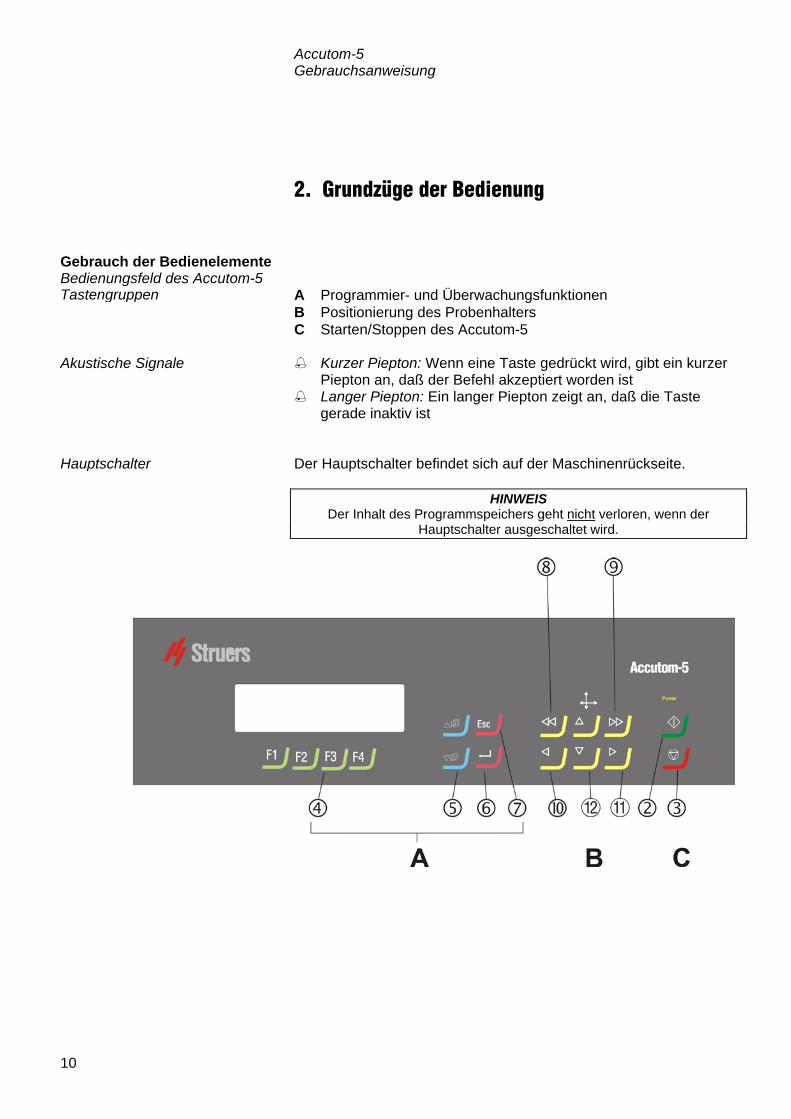
2. Grundzüge der Bedienung A Programmier- und Überwachungsfunktionen B Positionierung des Probenhalters C Starten/Stoppen des Accutom-5 Kurzer Piepton: Wenn eine Taste gedrückt wird, gibt ein kurzer
Piepton an, daß der Befehl akzeptiert worden ist Langer Piepton: Ein langer Piepton zeigt an, daß die Taste
gerade inaktiv ist Der Hauptschalter befindet sich auf der Maschinenrückseite.
Gebrauch der Bedienelemente Bedienungsfeld des Accutom-5 Tastengruppen
Akustische Signale
Hauptschalter
HINWEIS Der Inhalt des Programmspeichers geht nicht verloren, wenn der
Hauptschalter ausgeschaltet wird.

Accutom-5 Gebrauchsanweisung
11
Name Taste Funktion Name Taste Funktion
HAUPT-SCHALTER
Der Hauptschalter befindet sich auf der Maschinenrückseite.
ESC
Esc Verlassen des aktuellen Menübildschirms oder des Bildschirm mit der Probenhalterposition.
START
Starten des Trennverfahrens entsprechend der voreingestellten Methode. Das Umlaufkühlwasser wird eingeschaltet, sofern es ausgewählt wurde.
SCHNELL-POSITIO-NIERUNG
Springen zum Menü POSITION oder Bewegen des Probenhalters nach links in X-Richtung in Schritten von 100 µm. Halten Sie die Taste gedrückt, um die Geschwindigkeit zu erhöhen.
STOPP
Stoppen des Trennverfahrens. Das Umlaufkühlwasser wird ausgeschaltet, sofern es ausgewählt wurde.
SCHNELL-POSITIO-NIERUNG RECHTS
Springen zum Menü POSITION oder Bewegen des Probenhalters nach rechts in X-Richtung in Schritten von 100 µm. Halten Sie die Taste gedrückt, um die Geschwindigkeit zu erhöhen.
FUNKTIONS- TASTEN
F1/F2 F3/F4
Tasten für verschiedene Zwecke. Lesen Sie den unteren Teil der jeweiligen Einblendungen.
POSITIO-NIERUNG LINKS
Springen zum Menü POSITION oder langsames Bewegen des Probenhalters nach links in X-Richtung in Schritten von 5 µm. Halten Sie die Taste gedrückt, um die Geschwindigkeit zu erhöhen.
MENÜ
Zurückblättern () oder Vorblättern () in der Menübaumstruktur des Accutom-5. Wird ein Parameter geändert, so wird der Wert erhöht () oder verringert ().
POSITIO-NIERUNG RECHTS
Springen zum Menü POSITION oder langsames Bewegen des Probenhalters nach rechts in X-Richtung in Schritten von 5 µm. Halten Sie die Taste gedrückt, um die Geschwindigkeit zu erhöhen.
EINGABE
Ein markierter Parameterwert oder ein Menüpunkt wird ausgewählt.
POSITIO-NIERUNG AUF/AB
/
Springen zum Menü POSITION oder Bewegen des Probenhalters nach oben oder unten in Y-Richtung in Schritten von 100 µm. Halten Sie die Taste gedrückt, um die Geschwindigkeit zu erhöhen.
Tasten des Bedienungsfelds
Accutom-5 Gebrauchsanweisung
12
WÄHLE TRENNMETHODE
1.LEERE METHODE 2.LEERE METHODE 3.LEERE METHODE 4.LEERE METHODE 5.LEERE METHODE 6.LEERE METHODE 7.LEERE METHODE 8.LEERE METHODE 9.LEERE METHODE 10.LEERE METHODE 11.LEERE METHODE 12.LEERE METHODE F1:KOPIE F2:EINFÜG. F3:NULLST. F4:N.NAME
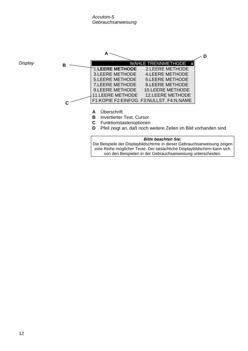
A Überschrift B Invertierter Text. Cursor C Funktionstastenoptionen D Pfeil zeigt an, daß noch weitere Zeilen im Bild vorhanden sind
Display
Bitte beachten Sie: Die Beispiele der Displaybildschirme in dieser Gebrauchsanweisung zeigen eine Reihe möglicher Texte. Der tatsächliche Displaybildschirm kann sich
von den Beispielen in der Gebrauchsanweisung unterscheiden.
B
C
A D

Accutom-5 Gebrauchsanweisung
13
Das Display kann verschiedene Arten von Informationen anzeigen, beispielsweise über die Trennmethode oder über die Probenposition. Ein Bildschirm zur Anzeige einer Trennmethode könnte wie das folgende Beispiel aussehen: Trennmethode: 1. LEERE METHODE Trennscheibe: B0D15 Geschw. : 2700 rpm Vorsch. :0,100 mm/s Kraft : MITTEL Rotation: AUS Kühlwasser: AN
Durch Drücken einer der Positionsstasten der X-Achse ändert sich die Anzeige folgendermaßen:
X-POSITIONEN
Absolute Position: 15,255 mm Relative Position: 5,000 mm F1:NULL F2:DICKE F3:GEHE ZU REL. NULL
Wenn Sie eine der Positionsstasten der Y-Achse drücken, ändert sich der Bildschirm folgendermaßen:
Y-POSITIONEN
Absolute Position: 55,7 mm Relative Position: 0,0 mm Stopposition : 20,0 mm F1:NULL F2:STOP DEF. F3:GEHE ZU REL.NULL
Esc Drücken Sie Esc, um zum Bildschirm für Trennmethoden zurückzugelangen.
Lesen des Displays
Die “dicken” Pfeile auf dem Display geben die Richtung an, in der der Probenhalter bewegt wird. Beispiel:
X-POSITIONEN
Y-POSITIONEN

Accutom-5 Gebrauchsanweisung
14
In Abhängigkeit vom Wertetyp gibt es zwei unterschiedliche Arten der Änderung. Trennmethode: 1. LEERE METHODE Trennscheibe: B0D15 Geschw. : 2700 rpm Vorsch. :0,100 mm/s Kraft : MITTEL Rotation: AUS Kühlwasser: AN
Drücken Sie MENÜ-AUF/AB , um den numerischen Wert auszuwählen, den Sie ändern wollen wollen, also beispielsweise Vorsch.:
Trennmethode: 1. LEERE METHODE Trennscheibe: B0D15 Geschw. : 2700 rpm Vorsch : 0,100 mm/s Kraft : MITTEL Rotation: AUS Kühlwasser: AN
Drücken Sie EINGABE , um den Wert zu ändern.
Zwei eckige Klammern [ ] werden um den Wert gesetzt.
Trennmethode: 1. LEERE METHODE Trennscheibe: B0D15 Geschw. : 2700 rpm Vorsch :[0,100]mm/s Kraft : MITTEL Rotation: AUS Kühlwasser: AN
Drücken Sie MENÜ-AUF/AB , um den numerischen Wert zu erhöhen oder zu verringern.
Drücken Sie EINGABE , um den neuen Wert zu bestätigen.
Oder:
Esc Drücken Sie Esc, um den ursprünglichen Wert zu behalten.
Werte ändern
Numerische Werte

Accutom-5 Gebrauchsanweisung
15
Trennmethode: 1. LEERE METHODE Trennscheibe: B0D15 Geschw. : 2700 rpm Vorsch : 0,100 mm/s Kraft : MITTEL Rotation: AUS Kühlwasser: AN
Drücken Sie MENÜ-AUF/AB , um den alphanu-merischen Wert auszuwählen, der geändert werden soll, also beispielsweise: Trennscheibe.
Drücken Sie EINGABE , um den Wert zu ändern.
Es wird ein Untermenü eingeblendet:
TRENNSCHEIBEN M0D08 M1D08 M0D10 M1D10 M0D13 M1D13 B0D13 B0C13 50A13 30A13 SAW13 M0D15 M1D15 E0D15 B0D15 B0C15 50A15 40A15 10S15 30A15 ANW. 1 ANW. 2 ANW. 3 ANW. 4 ANW. 5 ANW. 6 ANW. 7 ANW. 8 ANW. 9 ANW.10
Drücken Sie MENÜ-AUF/AB , um die richtige Trennscheibe auszuwählen.
Drücken Sie EINGABE , um den neuen Wert zu bestätigen und zur vorigen Bildschirmseite zurückzugelangen.
Oder:
Esc Drücken Sie Esc, um den ursprünglichen Wert beizubehal-ten und zur vorigen Bildschirmseite zurückzugelangen.
Alphanumerische Werte

Accutom-5 Gebrauchsanweisung
16
Nachdem Sie die Probe in den Probenhalter eingespannt haben, wird der Halter in den Probenhalterkopf gesetzt und dort befestigt. Zur Bewegung des Probenhalters und der Probe werden POSITION verwendet. Das Display zeigt die Position entweder in X- oder Y-Richtung. Wenn die Stromversorgung bei geschlossener Haube eingeschaltet wird, überprüft Accutom-5 die eigene Bezugsposition. Der Probenhalter wird zur Bezugsposition (X=0,000 Y=0,0) zurück-gefahren, und anschließend wird wieder die Position angefahren, die eingenommen wurde, bevor die Stromversorgung eingeschaltet worden ist. Die absolute Position zeigt die Gesamtstrecke, die der Probenhalter von der Bezugsposition zurückgelegt hat. Die relative Position entspricht so lange der absoluten Position, bis sie an einem gewünschten Punkt auf Null gesetzt wird. Durch die Nullsetzung wird die Berechnung der Probenbewegung in der Nähe der Trennscheibe erleichtert. Der Bildschirmwert bezieht sich immer auf die Strecke, die der Probenhalter seit der Nullsetzung zurückgelegt hat. Die relative Nullposition entspricht dem Punkt, an dem die relative Position entweder in X- oder Y-Richtung auf Null gesetzt wurde. Nach Abschluß des Trennprozesses kehrt der Probenhalter automatisch an diesen Punkt zurück. Wenn Sie während der Anzeige der X- oder Y-Position auf F3 drücken, kehrt die Probe auch zur relativen Nullposition zurück. Es kann eine Stopposition gesetzt werde, um den Trennprozeß an einem genau definierten Punkt anzuhalten. Wenn dieser Punkt erreicht worden ist, wird die Probe eingezogen, und der Probenhalter fährt an die relative Nullposition zurück. Achten Sie bitte darauf, daß Sie beim Einstellen der Stopposition einen eventuellen Verschleiß der Trennscheibe berücksichtigen. Dies ist besonders wichtig, wenn Sie Al2O3- oder SiC-Scheiben einsetzen.
Probe positionieren
Bezugsposition
Absolute Position
Relative Position
Relative Nullposition
Stopposition
Scheibenverschleiß ausgleichen

Accutom-5 Gebrauchsanweisung
17
Öffnen Sie die Haube und drehen Sie das rechte Kühlröhrchen in die Luft.
Führen Sie den Anschlagstift in die Bohrung des Innenflansches ein.
Lösen Sie die Flanschschraube mit Hilfe des Schlüssels (17 mm).
Nehmen Sie den Außenflansch und die Scheibe ab.
Montieren Sie die neue Trennscheibe und setzen Sie den
Außenflansch wieder auf, mit der bearbeiteten Seite gegen den Innenflasch.
Setzen Sie den Sperrstift in die Bohrung des Innenflansches ein. Befestigen Sie die Flanschschraube vorsichtig mit dem
Schlüssel. Drehen Sie das rechte Kühlröhrchen wieder in seine
ursprüngliche Position zurück.
Trennen Trennscheibe auswechseln
WICHTIG Die Toleranz zwischen Spindel und Innenflansch ist sehr gering, was
bedeutet, daß die beiden Flächen absolut sauber sein müssen. Versuchen Sie niemals, die Trennscheibe gewaltsam einzusetzen, da die Spindel auf
diese Weise beschädigt werden könnte. Wenn kleine Grate vorhanden sind, entfernen Sie diese mit Schleifpapier (Korngröße 1200).
Steckschlüssel
Anschlagstift Kühlwasserröhrchenmit Stopfen
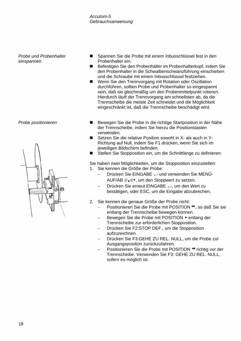
Accutom-5 Gebrauchsanweisung
18
Spannen Sie die Probe mit einem Inbusschlüssel fest in den Probenhalter ein.
Befestigen Sie den Probenhalter im Probenhalterkopf, indem Sie den Probenhalter in die Schwalbenschwanzführung einschieben und die Schraube mit einem Inbusschlüssel festziehen.
Wenn Sie den Trennvorgang mit Rotation oder Oszillation durchführen, sollten Probe und Probenhalter so eingespannt sein, daß sie gleichmäßig um den Probenmittelpunkt rotieren. Hierdurch läuft der Trennvorgang am schnellsten ab, da die Trennscheibe die meiste Zeit schneidet und die Möglichkeit eingeschränkt ist, daß die Trennscheibe beschädigt wird.
Bewegen Sie die Probe in die richtige Startposition in der Nähe
der Trennscheibe, indem Sie hierzu die Positionstasten verwenden.
Setzen Sie die relative Position sowohl in X- als auch in Y-Richtung auf Null, indem Sie F1 drücken, wenn Sie sich im jeweiligen Bildschirm befinden.
Stellen Sie Stopposition ein, um die Schnittlänge zu definieren: Sie haben zwei Möglichkeiten, um die Stopposition einzustellen: 1. Sie kennen die Größe der Probe:
− Drücken Sie EINGABE und verwenden Sie MENÜ-AUF/AB , um den Stoppwert zu setzen.
− Drücken Sie erneut EINGABE , um den Wert zu bestätigen, oder ESC, um die Eingabe abzubrechen.
2. Sie kennen die genaue Größe der Probe nicht:
− Positionieren Sie die Probe mit POSITION , so daß Sie sie entlang der Trennscheibe bewegen können.
− Bewegen Sie die Probe mit POSITION entlang der Trennscheibe zur erforderlichen Stopposition.
− Drücken Sie F2:STOP DEF., um die Stopposition aufzuzeichnen.
− Drücken Sie F3:GEHE ZU REL. NULL, um die Probe zur Ausgangsposition zurückzufahren.
− Positionieren Sie die Probe mit POSITION richtig vor der Trennscheibe. Verwenden Sie F3: GEHE ZU REL. NULL, sofern es möglich ist.
Probe und Probenhalter einspannen
Probe positionieren

Accutom-5 Gebrauchsanweisung
19
Alle Trennparameter können unabhängig voneinander geändert werden. Im Abschnitt „Werte ändern“ finden Sie Angaben darüber, wie Werte geändert werden können. Trennmethode: 1. LEERE METHODE Trennscheibe: B0D15 Geschw. : 2700 rpm Vorschub:0,100 mm/s Kraft : MITTEL Rotation: KONT. Geschw.: 3 Rich.: > < Kühlwasser: AN F3:ROT.TEST. F4:SICHERN Alle Struers-Trennscheiben sind mit ihren Standardwerten für Kraftgrenze, Scheibenstärke und Geschwindigkeit aufgelistet. Darüber hinaus wurden acht undefinierte Scheiben aufgenommen, damit Sie eine eigene Wahl von Trennscheiben treffen können. (Sehen Sie sich in diesem Zusammenhang „Konfiguration von Trennscheiben“ an.) Die Geschwindigkeit der Trennscheibe kann zwischen 300 und 3000 U/min in Schritten von 100 U/min eingestellt werden. Die Standardwerte wurden für alle Struers-Trennscheiben bereits zusammen mit den Scheibendefinitionen gespeichert. Wählen Sie eine andere Trennscheibe aus, wird die empfohlene Geschwindigkeit automatisch eingefügt. Die Vorschubgeschwindigkeit kann zwischen 0,005 mm/s und 3,000 mm/s eingestellt werden. (Im Abschnitt “Trennparameter” des Kapitels 3 “Verbrauchs-materialien” finden Sie empfohlene Einstellungen.) Die Kraftgrenze ist ein Schutz für die Trennscheibe und/oder die Proben, die getrennt werden sollen. In Abhängigkeit von der Dicke oder Festigkeit der Trennscheiben kann die Kraftgrenze auf drei verschiedene Werte eingestellt werden: NIEDRIG, MITTEL und HOCH. Die Standardwerte für sämtliche Struers-Trennscheiben wurden bereits zusammen mit den Scheibendefinitionen gespeichert. Wählen Sie eine andere Trennscheibe aus, wird die empfohlene Kraftgrenze automatisch eingefügt.
Trennparameter einstellen
Methodenschirm
Scheibe
Geschwindigkeit
Vorschub
Kraft

Accutom-5 Gebrauchsanweisung
20
Die Probenrotation kann vorteilhaft sein, wenn große, sehr harte, beschichtete oder sehr lange Proben getrennt werden. Bei der Accutom-5 sind drei unterschiedliche Einstellungen möglich. Die Probe rotiert nicht. Die Probe rotiert um ihren Mittelpunkt. Die Geschwindigkeit kann auf drei verschiedene Werte eingestellt werden: 1, 2 oder 3. Für die Rotationsrichtung gibt es zwei Möglichkeiten: entweder Gegenlauf oder Gleichlauf. Gegenlauf wird empfohlen. Drücken Sie F3, um die Probenrotation mit den eingestellten Parametern zu testen. Die Probe pendelt/oszilliert um ihren Mittelpunkt. Die Geschwindigkeit kann auf drei verschiedene Werte eingestellt werden: 1, 2 oder 3. Der Winkel kann von 10° bis 400° eingestellt werden. Drücken Sie F3, um die Probenrotation mit den eingestellten Parametern zu testen.
Das Kühlwasser kann entweder auf AN oder AUS gestellt werden. Bei allen normalen Trennvorgängen sollte die Einstellung AN lauten. Ehe Sie den Trennvorgang starten, vergewissern Sie sich, daß die Trennkammer sauber ist, damit das Kühlwasser ungehindert fließen kann. Positionieren Sie die Probe richtig. Stellen Sie die richtigen Trennparameter ein. Überzeugen Sie sich, ob die richtige Trennscheibe montiert
wurde. Schließen Sie die Haube der Maschine. Drücken Sie START .
Rotation Nur Accutom-5 mit Rotation
Rotation: aus
Rotation: kontinuierlich
Rotation: oszillierend
Achtung Wenn die Probe in die x- oder y- Richtung bewegt wird während Rotation
auf Kontinuierlich oder Oszillierend steht, dann blinkt kurzzeitig ein Warnbescheid "Rotationsmodus" auf der Anzeige als Erinnerung dass der
Rotationsmodus eingestellt ist.
Kühlwasser
Trennvorgang starten
Gleichlauf Gegenlauf

Accutom-5 Gebrauchsanweisung
21
Nachdem Sie START gedrückt haben, ändert sich das Display folgendermaßen: Vorschub TRENNEN GESTARTET 0% 100% Eingestellter Vorschub: 0,100 mm/s Aktueller Vorschub : 0,100 mm/s Restzeit des Vorgangs: 3 min Es wird sowohl die voreingestellte als auch die tatsächliche Vorschubgeschwindigkeit angezeigt. Während des Trennvorgangs kann die Vorschubgeschwindigkeit geändert werden. Drücken Sie einfach auf EINGABE und ändern Sie die Vorschubgeschwindigkeit auf den richtigen Wert. Drücken Sie EINGABE erneut, um die Änderung zu bestätigen, oder ESC, um abzubrechen. Die einzige Möglichkeit, die Probe zu bewegen, nachdem der Trennvorgang gestartet worden ist, besteht darin, die Probe von der Trennscheibe einzuziehen. Dieser Einzug erfolgt, wenn Sie ABWÄRTSPOSITION drücken. Die Vorwärtsbewegung der Proben wird gestoppt und die Probe rückwärts bewegt, bis die Taste wieder losgelassen wird. Anschließend bewegt sich die Probe wieder mit der voreingestellten Vorschubgeschwindigkeit vorwärts. Wenn die voreingestellte Vorschubgeschwindigkeit nicht erreicht werden kann, weil die Kraftgrenze erreicht ist, verringert Accutom-5 automatisch die Vorschubgeschwindigkeit auf die maximal mögliche Geschwindigkeit. Dieser Wert wird angezeigt, und wenn der Trennvorgang beendet ist, wird die folgende Nachricht auf dem Display angezeigt:
TRENNEN BEENDET
Kraftgrenze wurde erreicht, Vorschub wurde reduziert auf:
0,070 mm/sec
Wenn anschließend ähnliche Proben geschnitten werden sollen, sollte die Vorschubgeschwindigkeit auf den neuen Wert oder einen Wert reduziert werden, der kleiner ist.
Während des Trennvorgangs
Vorschubgeschwindigkeit ändern
Probe einziehen
Kraftgrenze erreicht

Accutom-5 Gebrauchsanweisung
22
Accutom-5 stoppt den Trennprozeß automatisch an der voreingestellten Stopposition. (Vergewissern Sie sich, daß ein eventueller Scheibenverschleiß berücksichtigt wird, wenn die Stopposition eingestellt wird.)
Die Probe wird anschließend eingezogen, und die Trennscheibe wird gestoppt.
Der Trennprozeß kann jederzeit während des Vorgangs gestoppt
werden, indem Sie STOPP drücken. Die Probe bleibt in ihrer gegenwärtigen Position, und der Prozeß wird dort abgebrochen.
Damit der Prozeß nicht gestoppt wird, solange sich die Trennscheibe noch in der Probe befindet, müssen Sie POSITION für die Y-Richtung und anschließend Sie F2: STOP DEF. drücken. Die Probe wird sofort eingezogen, und der Prozeß wird gestoppt, wenn die relative Nullposition erreicht wird.
Auf dem Display erscheint wird die Anzeige, die vorhanden war, als der Trennvorgang gestartet wurde.
Trennvorgang Stoppen Automatischer Stopp
Manueller Stopp

Accutom-5 Gebrauchsanweisung
23
3. Wartung Reinigen Sie die Trennkammer mit einem feuchten Tuch.
Verwenden Sie hierzu kein Leitungswasser, da die Gefahr besteht, daß der Umlaufkühlwassertank überläuft. Denken Sie daran, alle Schmutzpartikel aus dem Gitter zu entfernen.
Reinigen Sie den Probenhalterkopf und Schwalbenschwanz. Reinigen Sie die Flansche. Reinigen Sie die transparente Haube mit einem feuchten Tuch.
Der Flüssigkeitsstand in der Umlaufkühlung sollte nach 8 Arbeitsstunden , oder wenigstens jede Woche, überprüft werden. Wenn die Pumpe nicht mehr in das Kühlwasser eintaucht muss der Tank aufgefüllt werden. Denken Sie daran, Struers Additiv für Kühlwasser zuzusetzen, ein Teil Additiv auf 33 Teile Wasser. Die Konzentration des Additivs wird mit Hilfe eines Refraktometers gemessen: Konzentration = Brix. Es wird Additiv für Kühlflüssigkeit zugesetzt wenn die Konzentration unter 2,7% ist und Wasser wenn die Konzentration höher als 3,3 % ist.
Tägliche Wartungsarbeiten
WARNUNG! Verwenden Sie auf keinen Fall Alkohol, Aceton oder ähnliche
Lösungsmittel.
Die Umlaufkühlung kontrollieren
WICHTIG Achten Sie darauf, daß die Konzentration des Struers-Additivs im
Kühlwasser stets stimmt (das Mischungsverhältnis ist auf der Additivflasche angegeben). Denken Sie daran, das Struers-Additiv immer hinzuzufügen,
wenn Sie Wasser nachfüllen. Verwenden Sie keine Additive auf Öl-, Benzin- oder Terpentinbasis,
sondern ausschließlich die Struers-Additive.
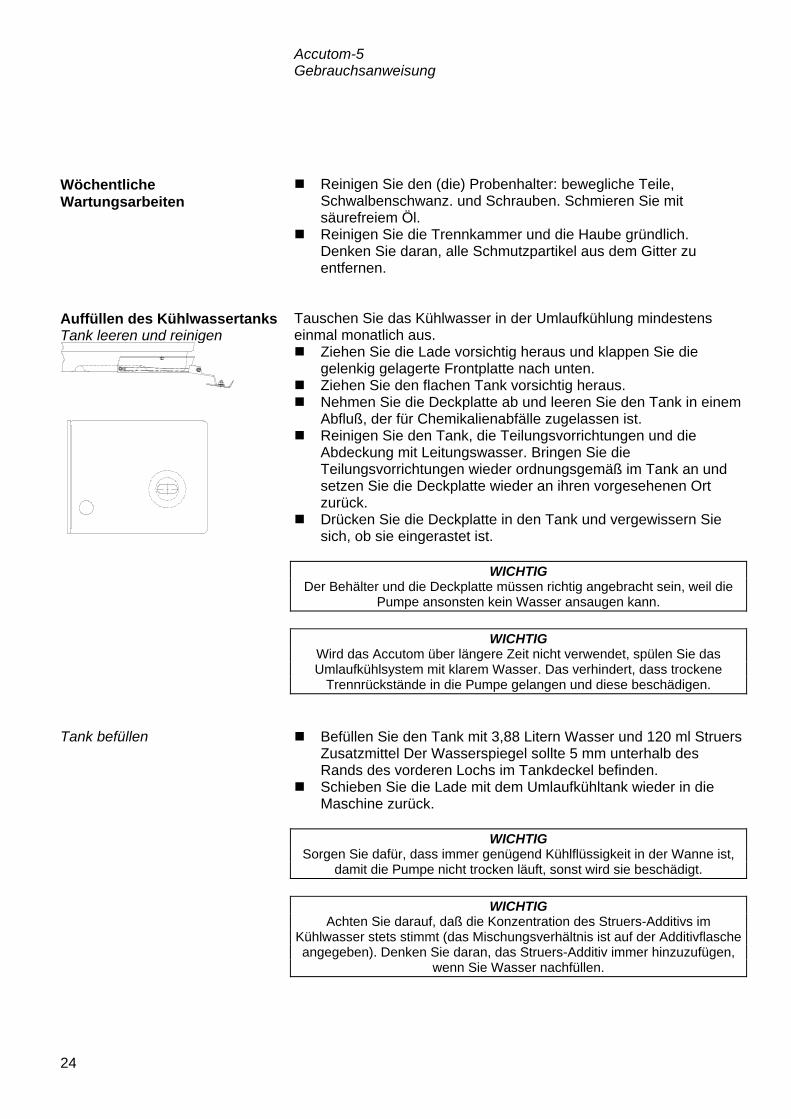
Accutom-5 Gebrauchsanweisung
24
Reinigen Sie den (die) Probenhalter: bewegliche Teile, Schwalbenschwanz. und Schrauben. Schmieren Sie mit säurefreiem Öl.
Reinigen Sie die Trennkammer und die Haube gründlich. Denken Sie daran, alle Schmutzpartikel aus dem Gitter zu entfernen.
Tauschen Sie das Kühlwasser in der Umlaufkühlung mindestens einmal monatlich aus. Ziehen Sie die Lade vorsichtig heraus und klappen Sie die
gelenkig gelagerte Frontplatte nach unten. Ziehen Sie den flachen Tank vorsichtig heraus. Nehmen Sie die Deckplatte ab und leeren Sie den Tank in einem
Abfluß, der für Chemikalienabfälle zugelassen ist. Reinigen Sie den Tank, die Teilungsvorrichtungen und die
Abdeckung mit Leitungswasser. Bringen Sie die Teilungsvorrichtungen wieder ordnungsgemäß im Tank an und setzen Sie die Deckplatte wieder an ihren vorgesehenen Ort zurück.
Drücken Sie die Deckplatte in den Tank und vergewissern Sie sich, ob sie eingerastet ist.
Befüllen Sie den Tank mit 3,88 Litern Wasser und 120 ml Struers
Zusatzmittel Der Wasserspiegel sollte 5 mm unterhalb des Rands des vorderen Lochs im Tankdeckel befinden.
Schieben Sie die Lade mit dem Umlaufkühltank wieder in die Maschine zurück.
Wöchentliche Wartungsarbeiten
Auffüllen des Kühlwassertanks Tank leeren und reinigen
WICHTIG Der Behälter und die Deckplatte müssen richtig angebracht sein, weil die
Pumpe ansonsten kein Wasser ansaugen kann.
WICHTIG Wird das Accutom über längere Zeit nicht verwendet, spülen Sie das Umlaufkühlsystem mit klarem Wasser. Das verhindert, dass trockene
Trennrückstände in die Pumpe gelangen und diese beschädigen.
Tank befüllen
WICHTIG Sorgen Sie dafür, dass immer genügend Kühlflüssigkeit in der Wanne ist,
damit die Pumpe nicht trocken läuft, sonst wird sie beschädigt.
WICHTIG Achten Sie darauf, daß die Konzentration des Struers-Additivs im
Kühlwasser stets stimmt (das Mischungsverhältnis ist auf der Additivflasche angegeben). Denken Sie daran, das Struers-Additiv immer hinzuzufügen,
wenn Sie Wasser nachfüllen.

Accutom-5 Gebrauchsanweisung
25
Die Genauigkeit der Diamant- und CBN-Trennscheiben und damit des Schnitts hängt davon ab, wie sorgfältig die nachstehenden Anweisungen eingehalten werden: Die Trennscheibe darf niemals etwa durch schwere
mechanische oder thermische Belastungen überlastet werden. Lagern Sie die Trennscheibe an einem trockenen Ort horizontal
auf einer ebenen Unterlage, und zwar vorzugsweise unter leichtem Druck.
Eine saubere und trockene Trennscheibe korrodiert nicht. Aus diesem Grund müssen Sie die Trennscheibe vor dem Lagern reinigen und trocknen. Wenn möglich, sollten Sie gewöhnliche Reinigungsmittel für die Reinigung verwenden.
Ein regelmäßiges Abrichten der Trennscheibe ist ebenfalls Teil der allgemeinen Wartung (siehe DETAILS UND BESONDERHEITEN DER BEDIENUNG).
Diese Trennscheiben sind feuchtigkeitsempfindlich. Aus diesem Grund sollten Sie keine neuen, trockenen und gebrauchte, feuchte Trennscheiben zusammenbringen. Lagern Sie die Trennscheiben an einem trockenen Ort horizontale auf einer ebenen Unterlage.
Wartung der Trennscheiben Wartung der Diamant- und CBN-Trennscheiben
Abrasive Trennscheiben lagern

Accutom-5 Gebrauchsanweisung
26
Referenzhandbuch Inhaltsverzeichnis Seite
1. Details und Besonderheiten der Bedienung Konfigurationsmenü ......................................................................... 27
Trennscheiben ........................................................................ 28 Optionen ................................................................................. 29
Manuelle Funktionen ........................................................................ 30 Probenrotation ........................................................................ 31 Kühlwasserpumpe .................................................................. 32 Abrichten ................................................................................. 33
Methodenoptionen ........................................................................... 35 Methode speichern ................................................................. 35 Methode kopieren ................................................................... 36 Methode einfügen ................................................................... 37 Methode nullstellen ................................................................. 38 Namen ändern ........................................................................ 39 Prinzipien der Namensänderung ............................................ 40
2. Zubehör ................................................................................... 41
3. Verbrauchsmaterialien Trennscheiben ................................................................................. 42 Trennergebnisse optimieren ............................................................ 42
Trennparameter ...................................................................... 42 Allgemeine Fragen zum Trennvorgang ................................... 43
Verbrauchsmaterialien ..................................................................... 43
4. Fehlersuche ........................................................................... 44
5. Technische Daten ................................................................. 46
6. Menüstruktur ......................................................................... 47
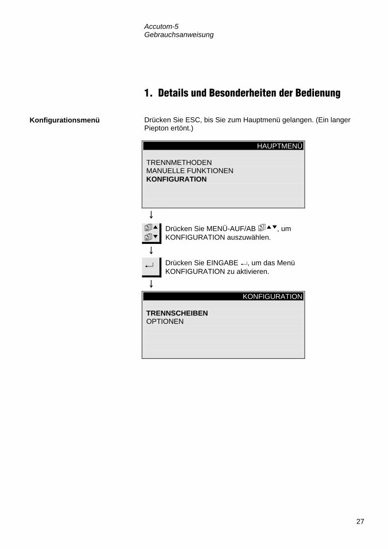
Accutom-5 Gebrauchsanweisung
27
1. Details und Besonderheiten der Bedienung Drücken Sie ESC, bis Sie zum Hauptmenü gelangen. (Ein langer Piepton ertönt.)
HAUPTMENÜ TRENNMETHODEN MANUELLE FUNKTIONEN KONFIGURATION
Drücken Sie MENÜ-AUF/AB , um KONFIGURATION auszuwählen.
Drücken Sie EINGABE , um das Menü KONFIGURATION zu aktivieren.
KONFIGURATION TRENNSCHEIBEN OPTIONEN
Konfigurationsmenü

Accutom-5 Gebrauchsanweisung
28
Wenn Sie andere als Struers Trennscheiben verwenden wollen, so müssen sie jene konfigurieren, so daß sie die richtigen Werte für Kraftgrenze, Scheibendicke und -geschwindigkeit enthalten. Um Ihre eigenen Trennscheiben zu konfigurieren, gehen Sie folgendermaßen vor:
Drücken Sie MENÜ-AUF/AB , um TRENNSCHEIBEN auszuwählen.
Drücken Sie EINGABE , um das Menü TRENNSCHEIBEN zu aktivieren.
KONFIGURATION DER TRENNSCHEIBEN Trennscheibe : ANW. 1 Kraftgrenze : MITTEL Scheibendicke : 0,50 mm Geschwindigkeit: 3000 rpm F1:VORIGE SCH. F2:NÄCHSTE SCH. F4:N.NAME
Drücken Sie MENÜ-AUF/AB , um den Wert auszuwählen, der geändert werden soll.
Drücken Sie EINGABE , um den Wert zu ändern. Nachdem Sie den Wert geändert haben,
Drücken Sie EINGABE , um den neuen Wert zu be-stätigen und zum letzten Bildschirm zurückzukehren.
F4 Drücken Sie F4, um die Trennscheibe umzubenennen. (Einzelheiten hierzu finden Sie unter „Namen ändern“.)
Trennscheiben

Accutom-5 Gebrauchsanweisung
29
Im Menü OPTIONEN können verschiedene Einträge konfiguriert werden. Im Abschnitt „Zu Beginn“ dieser Gebrauchsanweisung können Sie nachlesen, wie die Sprache geändert wird. Nachdem die Stopposition erreicht wurde, wird die Probe direkt zur relativen Nullposition zurückgefahren. Um jeglichen Kontakt mit der Trennscheibe während dieser Bewegung zu vermeiden, kann die Probe von der Scheibe zurückgezogen werden, ehe die Scheibe neu positioniert wird indem der X-Einzug auf EIN gesetzt wird. Nach Erreichen der relativen Nullposition wird die Probe dann in die ursprüngliche Position zurückgefahren.
Die Kontrasteinstellung der Anzeige kann eingestellt werden. Durch das Drücken auf F1 wird die gewählte Option wieder auf die Firmenseitig eingestellten Werte rückgestellt.
Optionen
Sprache
X-Einzug
WICHTIG Vergewissern Sie sich, daß die Y-Stopposition richtig gesetzt wurde. Wenn die Probe nicht durchtrennt wurde, ehe die Probe eingezogen wird, könnte
die Trennscheibe beschädigt werden.
Kontrast
F1: STANDARD

Accutom-5 Gebrauchsanweisung
30
Mehrere Funktion können bei Accutom-5 auch manuell ausgeführt werden. Alle diese Funktionen stehen im Menü MANUELLE FUNKTIONEN zur Verfügung. Drücken Sie ESC, bis Sie zum Hauptmenü gelangen.
HAUPTMENÜ TRENNMETHODEN MANUELLE FUNKTIONEN KONFIGURATION
Drücken Sie MENÜ-AUF/AB , um MANUELLE FUNKTIONEN auszuwählen.
Drücken Sie EINGABE , um das Menü MANUELLE FUNKTIONEN zu aktivieren.
MANUELLE FUNKTIONEN PROBENROTATION KÜHLWASSERPUMPE ABRICHTEN DER TRENNSCHEIBE
Manuelle Funktionen

Accutom-5 Gebrauchsanweisung
31
Drücken Sie MENÜ-AUF/AB , um PROBENROTATION auszuwählen.
Drücken Sie EINGABE , um das Menü PROBENROTATION zu aktivieren.
PROBENROTATION PROBENROTATION: KONTINUIERLICH Geschwindigkeitsstufe: 1 Richtung: > < F1: ROTATION STARTEN
Drücken Sie MENÜ-AUF/AB , um den Wert auszuwählen, der geändert werden soll.
Drücken Sie EINGABE , um den Wert zu ändern.
Nachdem Sie den Wert geändert haben,
Drücken Sie EINGABE , um den neuen Wert zu bestätigen und zum vorigen Bildschirm zurückzukehren.
F1 Drücken Sie F1, um die Rotation zu starten und um zu
überprüfen, ob alles richtig ausgerichtet ist. Drücken Sie F1 erneut, um die Rotation zu stoppen.
Probenrotation

Accutom-5 Gebrauchsanweisung
32
Vom Menü MANUELLE FUNKTIONEN, drücken Sie MENÜ-AUF/AB , um Kühlwasserpumpe zu wählen.
MANUELLE FUNKTIONEN
PROBENROTATION KÜHLWASSERPUMPE ABRICHTEN DER TRENNSCHEIBE
Drücken Sie EINGABE , um die Option KÜHLWASSERPUMPE zu aktivieren.
KÜHLWASSERPUMPE F1: PUMPE STARTEN
F1 Drücken Sie F1, um die Kühlwasserpumpe zu starten. Drücken Sie F1, um die Kühlwasserpumpe wieder zu stoppen.
Kühlwasserpumpe

Accutom-5 Gebrauchsanweisung
33
Diamant- und CBN-Trennscheiben müssen eventuell abgerichtet werden, um die Scheibe wieder zu öffnen und eine maximale Wirkung zu erzielen, wenn zähe Materialien getrennt worden sind. Dieses Abrichten können Sie folgendermaßen durchführen: Setzen Sie die Trennscheibe ein, die abgerichtet werden soll. Spannen Sie den Abrichtstab in den Probenhalter ein und
positionieren Sie ihn ordnungsgemäß. − Der Abrichtstab muß sich vor der Scheibe befinden, so daß
die Scheibe vom Abrichtstab Scheiben abtrennen kann.
Vom Menü MANUELLE FUNKTIONEN, drücken Sie MENÜ-AUF/AB , um ABRICHTEN zu wählen.
MANUELLE FUNKTIONEN PROBENROTATION KÜHLWASSERPUMPE ABRICHTEN DER TRENNSCHEIBE
Drücken Sie EINGABE , um die Abrichtoption zu aktivieren.
Abrichten
Abrichten der Trennscheibe

Accutom-5 Gebrauchsanweisung
34
ABRICHTEN DER TRENNSCHEIBE Vorschub : 0.5 mm/s Scheibengeschwindigkeit: 3000 rpm Kühlwasser : AN Y-Abstand: 10.0 mm F1: ABRICHTEN STARTEN
Drücken Sie MENÜ-AUF/AB , um den Wert auszuwählen, der geändert werden soll.
Drücken Sie EINGABE , um den Wert zu ändern.
Drücken Sie EINGABE , um den neuen Wert zu bestätigen und um zum vorigen Bildschirm zurückzukehren.
F1 Drücken Sie F1, um den Abrichtvorgang zu starten.

Accutom-5 Gebrauchsanweisung
35
Während Sie mit einer speziellen Methode arbeiten, können Sie Änderungen, die Sie vorgenommen haben, in der Datenbank speichern. Sobald ein Parameter in einer Trennmethode geändert wird, wird
F4:SICHERN in der untersten Zeile des Displays angezeigt. Trennmethode: 1. LEERE METHODE Trennscheibe: B0D15 Geschw. : 2700 rpm Vorsch. :0.100 mm/s Kraft : MITTEL Rotation: AUS Kühlwasser: AN F4:SICHERN
F4 Drücken Sie F4:SICHERN, um die Änderungen zu speichern, nachdem alle Parameter geändert worden sind.
METHODE SICHERN
Änderungen sichern in 1. LEERE METHODE ? EINGABE: JA ESC: NEIN
Drücken Sie EINGABE , um die geänderte Methode zu sichern.
Sofern Sie nicht bereits einen Namen für die Methode ausgewählt haben, wird der Name automatisch von LEERE METHODE in UNBENANNTE METH. geändert. Hiermit wird angezeigt, daß mindestens ein Parameter im Vergleich zur Standardmethode modifiziert worden ist.
Methodenoptionen Methode speichern
Wichtig Wenn Änderungen gesichert werden, wird die Ausgangsmethode
überschrieben. Wenn Sie die Ausgangsmethode behalten wollen, sollten Sie eine Kopie der Methode mit einem neuen Namen anlegen, so daß die
Änderungen in einer Kopie und nicht in der Ausgangsmethode vorgenommen werden. Weitere Informationen finden Sie im Abschnitt
„Methode kopieren“.

Accutom-5 Gebrauchsanweisung
36
Das Kopieren einer Methode ist ein abkürzendes Verfahren, um eine neue Trennmethode auf der Grundlage einer bereits vorhandenen Methode zu erstellen. Wählen Sie die Trennmethode aus, von der Sie eine Kopie
erstellen möchten.
WÄHLE TRENNMETHODE 1.UNBENANNTE METH. 2.LEERE METHODE 3.LEERE METHODE 4.LEERE METHODE 5.LEERE METHODE 6.LEERE METHODE 7.LEERE METHODE 8.LEERE METHODE 9.LEERE METHODE 10.LEERE METHODE 11.LEERE METHODE 12.LEERE METHODE F1:KOPIE F3:NULLST. F4:N.NAME
Drücken Sie EINGABE , wenn Sie sich die Methodenparameter ansehen möchten.
Esc Drücken Sie ESC, um zur obigen Anzeige zurückzukehren.
F1 Drücken Sie F1:KOPIE, um die Methode in den Pufferspeicher zu kopieren.
METHODE KOPIEREN Soll die flg. Methode kopiert werden ? 1. UNBENANNTE METH. EINGABE: JA ESC: NEIN
Drücken Sie EINGABE , um zu bestätigen, daß die Methode in den Speicher kopiert werden soll.
Methode kopieren

Accutom-5 Gebrauchsanweisung
37
Wenn Sie eine Methode in eine andere Methode einfügen wollen:
Drücken Sie MENÜ-AUF/AB , um die Methode auszuwählen , in die Sie die Methode einfügen wollen.
Wenn es sich nicht um eine LEERE METHODE handelt: Drücken Sie EINGABE , um sich diese Methode
anzusehen.
Esc Drücken Sie ESC, um zur obigen Anzeige zurückzukehren.
F2 Drücken Sie F2:EINFÜG., um die Methode aus dem Speicher einzufügen.
METHODE EINFÜGEN Soll vom Speicher in Methode 3. LEERE METHODE kopiert werden ? EINGABE: JA ESC: NEIN
Drücken Sie EINGABE , um zu bestätigen, daß die Methode eingefügt werden soll.
Methode einfügen

Accutom-5 Gebrauchsanweisung
38
Wenn eine Methode nicht mehr gebraucht wird, sollte sie nullgestellt werden. Die Parameter werden auf die Standardwerte geändert, die später ganz einfach in eine neue Methode geändert werden können. Der Methodenname wird auf LEERE METHODE geändert und teilt Ihnen auf diese Weise mit, daß Sie diese Methode modifizieren können, ohne wertvolle Daten ersetzen zu müssen. Wählen Sie die Methode aus, die Sie nullstellen wollen.
WÄHLE TRENNMETHODE 1.UNBENANNTE METH. 2.LEERE METHODE 3.LEERE METHODE 4.UNBENANNTE METH. 5.LEERE METHODE 6.LEERE METHODE 7.LEERE METHODE 8.LEERE METHODE 9.LEERE METHODE 10.LEERE METHODE 11.LEERE METHODE 12.LEERE METHODE F1:KOPIE F2:EINFÜG. F3:NULLST.F4:N.NAME
Drücken Sie EINGABE , um sich die Methode anzusehen und um sicherzugehen, daß Sie keine wertvollen Daten löschen.
Esc Drücken Sie ESC, um zur obigen
Anzeige zurückzukehren.
F3 Drücken Sie F3:NULLST.
METHODE NULLSTELLEN Soll diese Methode nullgestellt werden ? 1. UNBENANNTE METH. EINGABE: JA ESC: NEIN
Drücken Sie EINGABE , um die Methode nullzustellen.
Methode nullstellen

Accutom-5 Gebrauchsanweisung
39
Die Namen für die Methoden und Trennscheiben können nach Belieben geändert und ausgetauscht werden. Wählen Sie die Methode oder Trennscheibe aus, die Sie
umbenennen wollen.
WÄHLE TRENNMETHODE 1.UNBENANNTE METH. 2.LEERE METHODE 3.LEERE METHODE 4.UNBENANNTE METH 5.LEERE METHODE 6.LEERE METHODE 7.LEERE METHODE 8.LEERE METHODE 9.LEERE METHODE 10.LEERE METHODE 11.LEERE METHODE 12.LEERE METHODE F1:KOPIE F2:EINFÜG. F3:NULLST. F4:N.NAME
F4 Drücken Sie F4:N.NAME.
UNBENANNTE METH. NAME EDITIEREN Text: UNBENANNTE METH. Drücke EINGABE um Text zu behalten, oder drücke ““ um neue Zeichen zu wählen F1:LINKS F2:EINFÜG. F3:LÖSCHEN F4:RECHTS
Drücken Sie MENÜ-AB:, um zum Zeichensatz zu gelangen.
UNBENANNTE METH. NAME EDITIEREN Text: UNBENANNTE METH. ABCDEFGHIJKLMNOPQRSTUVWXYZ 0123456789,.;:-!"#%&/()=?+µ F1:LINKS F2:EINFÜG F3:LÖSCHEN F4:RECHTS
Namen ändern

Accutom-5 Gebrauchsanweisung
40
Führen Sie den Hauptcursor mit Hilfe von F1:LINKS oder F4:RECHTS auf das Zeichen, das Sie ändern wollen. Verwenden Sie MENÜ-AB , um zum nächsten Zeichensatz in der nachfolgenden Zeile zu gelangen. Ein Hilfscursor in der Textzeile gibt die Position im Methodennamen an.
Schreiben Sie den neuen Namen mit Hilfe der folgenden Tasten: F1 Hiermit wird der Hauptcursor nach links bewegt. F2 Es wird ein Leerzeichen in den Text eingefügt. F3 Es wird ein Zeichen im Text gelöscht. F4 Hiermit wird der Hauptcursor nach rechts bewegt. Mit EINGABE wird das neue Zeichen in den
Methodennamen übernommen und der Hilfscursor im Namen nach rechts bewegt. Wiederholen Sie das Verfahren für alle Zeichen.
Schreiben Sie den neuen Namen mit Hilfe der obigen Namensänderungsverfahren.
Esc Drücken Sie ESC, um den Editor wieder zu verlassen.
NAME GEÄNDERT Name geändert,wollen Sie den alten Namen behalten oder den neuen akzeptieren? EINGABE:NEUER NAME ESC:ALTER NAME
Drücken Sie EINGABE , um den neuen Namen zu bestätigen.
Prinzipien der Namensänderung

Accutom-5 Gebrauchsanweisung
41
2. Zubehör Spezifikation Kat. Nr. Für Trennscheiben. 65 mm Durchmesser. Zum Einsatz in Accutom-5, um höchste Präzision zu erzielen.
04946902
Spezifikation Kat. Nr. Für allgemeinen Einsatz. Schraubstock mit maximaler Öffnung von 60 mm.
04946903
Für runde oder quadratische Proben. Tropfen-form mit maximalem Öffnungsdurchmesser von 40 mm / 1 ½"
04946904
Für unregelmäßige Proben mit 7 Schrauben. Maximale Breite: 40 mm / 1 ½”
04946905
Mit Goniometer 04276911 Für aufklebbare Proben 04276912 Mit Vakuumspannvorrichtung für Dünnschliffe 04276913 Für sehr kleine Proben. Schraubstocktyp 04276915 Doppel-Parallel-Schraubstock 04946909 Gelenke, die zwischen Schwalbenschwanz-führung und Probehalter montiert werden Kippgelenk mit maximalem Winkel von ± 10°
04946906
Winkelgelenk mit maximalem Winkel von +30/-90°
04946908
Sockelplatte mit Schwalbenschwanz. Für die Montage anderer Arten von Probenhaltern.
04276914
Flanschsätze
Probenhalter

Accutom-5 Gebrauchsanweisung
42
3. Verbrauchsmaterialien Siehe Tabelle zur Auswahl der Trennscheiben in der Broschüre für Trennscheiben. Accutom-5 akzeptiert Trennscheiben mit einem Durchmesser von 75 mm (der kleinste Flansch hat einen Durchmesser von 42 mm) bis 152 mm. Bohrung: 12,7 mm.
In der folgenden Tabelle können Sie die richtigen Scheiben- und Trennparameter entsprechend dem Probenmaterial auswählen. Empfohlene Trennparameter Material Härte Kraft-
grenze Vorschub-geschwin-digkeit [mm/s]
Drehzahl [U/min]*)
Keramik, Mineralien und Kristalle > HV 800
gering 0,005-0,15 3000 gering 0,005-0,20 3000 hoch 0,005-0,30 3000 hoch 0,005-0,30 2700
Hartmetalle und Hartkeramik > HV 800
mittel 0,005-0,25 3000 mittel 0,005-0,25 2700
Extrem harte Eisenmetalle > HV 500 mittel 0,005-0,25 3000
Harte und sehr harte Eisenmetalle HV 350-800
mittel 0,05-0,30 1000-3000 mittel 0,05-0,30 1000-3000
Harte und sehr harte Eisenmetalle, größere Proben
HV 350-800 mittel 0,05-0,30 1000-3000
Weiche und mittelweiche Metalle HV 30-350
mittel 0,05-0,30 1000-3000
mittel 0,05-0,30 1000-3000 Weiche und zähe Nichteisenmetalle HV 70-400 mittel 0,05-0,30 1000-3000
Kunststoffe und sehr weiche Metalle < HV 100 mittel 0,05-0,30 max. 1200
*) Um einen geringeren Scheibenverschleiß und eine bessere Oberflächengüte zu erzielen, verwenden Sie stets die empfohlene Scheibendrehzahl.
Trennscheiben
WICHTIG! Verwenden Sie stets große Flansche (65 mm), um die größtmögliche
Genauigkeit zu erzielen.
Trennergebnisse optimieren Trennparameter

Accutom-5 Gebrauchsanweisung
43
In der folgenden Tabelle finden Sie mögliche Antworten auf eine Reihe allgemeiner Fragen zum Trennvorgang: Trennergebnisse optimieren Ziel Umsetzung Besser Oberflächengüte
Verwenden Sie die geringste empfohlene Vorschubgeschwindigkeit und keine Rotation des Probenhalters.
Geringerer Scheiben-verschleiß
Verwenden Sie die geringste empfohlene Vorschub-geschwindigkeit und keine Rotation des Probenhalters. Dies ist bei den Scheiben mit Bakelitbindung und allen abrasiven Trennscheiben besonders wichtig.
Probleme mit Schleiftrenn-scheiben?
Die Schleiftrennscheiben sollten nicht außerhalb des empfohlenen Vorschubgeschwindigkeitsbereichs eingesetzt werden. Ist die Vorschubgeschwindigkeit geringer als empfohlen, werden unregelmäßige Oberflächen erzeugt. Bei höherer Vorschubgeschwindigkeit tritt übermäßiger Scheibenverschleiß zusammen mit einem erhöhten Scheibenbruchrisiko auf.
Plane Proben Arbeiten Sie hauptsächlich mit geringerer Vorschubgeschwindigkeit, die höchsten empfohlenen Scheibengeschwindigkeiten, größtmöglichen Flansche und keine Probenhalterrotation. Der erste Kerbschnitt ist besonders kritisch. Wenn die Anfangsvorschubgeschwindigkeit zu groß ist, verbiegt sich die Scheibe und beginnt den Trennvorgang angewinkelt. Ein solcher Trennschnitt kann niemals eben sein.
Bessere Parallelität
Verwenden Sie die geringste empfohlene Vorschubgeschwindigkeit.
Schnellerer Trennvorgang
Richten Sie die Probe so aus, daß die Scheibe den kleinstmöglichen Querschnitt schneidet, und verwenden Sie dann die empfohlene maximale Vorschubgeschwindigkeit.
Spezifikation Kat. Nr.
Corrozip Umweltfreundliches Zusatzmittel für Kühlwasser. Schützt die Trennmaschinen vor Korrosion und verbessert die Trenn- und Kühlqualität. Für Umlaufkühleinheit. 1 l 5 l
449900045 449900046
Wasserfreie Trennflüssigkeit Zum Trennen von wasserempfindlichen Werkstoffen 5 l
49900030
Allgemeine Fragen zum Trennvorgang
Verbrauchsmaterialien

Accutom-5 Gebrauchsanweisung
44
4. Fehlersuche
Displaymeldung Erläuterung Maßnahme Suche XY-Referenzposition Die Maschine sucht die
Ausgangsreferenzpositionen Warten Sie, bis der Suchprozeß abgeschlossen ist
Ref.-Pos. nicht gefunden, Haube schließen
Accutom-5 wurde mit offener Haube gestartet und suchte nicht nach der Referenzposition
Schließen Sie die Haube, warten Sie, bis die Suche nach der Referenzposition abgeschlossen ist, und drücken Sie erneut auf START
Haube offen! Sie versuchen, den Trenn oder Abrichtvorgang zu starten, während die Haube offen ist
Schließen Sie die Haube und drücken Sie erneut auf START
Vorgang wegen offener Haube gestoppt
Sie haben die Haube während eines Trenn oder Abrichtvorgangs geöffnet
Schließen Sie die Haube und starten Sie den unterbrochenen Vorgang
Vorgang läuft Sie versuchen, zwei verschiedene Vorgänge gleichzeitig zu starten
Warten Sie, bis der vorangegangenen Vorgang beendet worden ist, und starten Sie einen neuen Versuch
Y-Stoppos. außerhalb des Trennbereichs
Die eingestellte Stopposition liegt außerhalb des Maximalbereichs in Y-Richtung (max. 105,0 mm)
Stellen Sie Y-Stopposition ein
Y-Stopposition kleiner als Y-Rel.-Pos.
Sie versuchen, einen Trennvorgang zu starten, während die relative Y-Position größer oder gleich der Y-Stopposition ist
Positionieren Sie den Probenhalter richtig und/oder ändern Sie die Y-Stopposition
Vorschub weniger als 90% der Vorgabe
Die Kraft hat die Kraftgrenze (NIEDRIG, MITTEL, HOCH) überschritten, und die Vorschubgeschwindigkeit wird automatisch reduziert
Verringern Sie die Vorschubgeschwindigkeit oder erhöhen Sie die Kraftgrenze, wenn Sie das nächstemal dasselbe Material schneiden
Vorgang gestoppt, Vorschub zu gering
Die Vorschubgeschwindigkeit wurde auf weniger als 10% reduziert, weil die Kraft die Kraftgrenze überschritten hat
Verringern Sie die Vorschubgeschwindigkeit, erhöhen Sie die Kraftgrenze oder tauschen Sie die Trennscheibe aus und starten Sie den Trennvorgang erneut
Trennmethode nicht gewählt START wurde gedrückt, ehe eine Trennmethode ausgewählt wurde
Wählen Sie eine Methode aus und drücken Sie erneut auf START
Abrichtbereich überschritten Der Parameter Y-Abstand wurde auf einen Wert eingestellt, der größer als die mögliche Tischbewegung ist
Stellen Sie den Y-Abstand ein und drücken Sie erneut auf START

Accutom-5 Gebrauchsanweisung
45
Fehlermeldungen X-MIN-Sensor nicht aktiviert Der Induktivsensor kann die
Endposition des X-Tisches nicht erfassen
Überprüfen Sie, ob der Tisch mechanisch blockiert ist. Ist dies nicht der Fall, rufen Sie einen Kundendiensttechniker von Struers
X-MIN-Sensor nicht deaktiviert Der Induktivsensor für die X-Position läßt sich nicht deaktivieren
Überprüfen Sie, ob der Tisch mechanisch blockiert ist. Ist dies nicht der Fall, rufen Sie einen Kundendiensttechniker von Struers
Encoder-Fehler Der Y-Tisch bewegt sich nicht, oder der Encoder ist defekt
Überprüfen Sie, ob der Tisch mechanisch blockiert ist. Ist dies nicht der Fall, rufen Sie einen Kundendiensttechniker von Struers
Schleifmotor überlastet Der Hauptmotor wurde über einen längeren Zeitraum einer hohen Last ausgesetzt
Warten Sie, bis sich der Motor abgekühlt hat. “Trennmotor wieder bereit nach Überlast” wird im Display eingeblendet. Stellen Sie die Prozeßparameter ein, um Wiederholungen zu vermeiden
Geräre Probleme Erläuterung Maßnahme Die Pumpe der Umlaufkühleinheit funktioniert nicht richtig
Der Wasserstand in der Umlaufkühlwanne ist zu niedrig
Prüfen Sie ob genügend Wasser in der Wanne ist
Der Wasserauslauf ist verstopft Entfernen Sie die Kühlschläuche und lassen Sie die Pumpe laufen. Spülen Sie die Schläuche mit klarem Wasser bevor Sie sie wieder anschliessen
Die Pumpe der Umlaufkühleinheit ist mit Trennrückständen verunreinigt
Spülen Sie die Pumpe mit klarem Wasser indem Sie das Wasser vorsichtig in das Ansaugrohr drücken.

Accutom-5 Gebrauchsanweisung
46
5. Technische Daten
Gegenstand Spezifikationen Trennen Trenngeschwindigkeit: 300-3000 U/min (einstellbar in Schritten von
100 U/min) Vorschubgeschwindigkeit: 0,005-3,000 mm/s (einstellbar in Schritten von 0,005 mm/s) Max. Positioniergeschwindigkeit: Y = 13 mm/s, X = 13 mm/s Kraftgrenzen: gering: etwa 20N; mittel: etwa 40N; hoch: etwa 60N
Positionierbereich Y-Richtung: 105 mm (Genauigkeit: 0,1 mm) X-Richtung: 60 mm (Genauigkeit: 0,005 mm)
Probengröße Max. Länge der Trennprobe: 30 mm, 140 mm bei ø 20 mm Max. Länge der einzuspannenden Probe: 225 mm Max. Querschnitt der Probe: Trennscheibe: ø 127mm und Flansch: ø 42mm: ø40mm (ohne Rotation) ø80mm (mit Rotation) Trennscheibe: ø 152mm und Flansch: ø 42mm: ø50mm (ohne Rotation) ø100mm (mit Rotation)
Trennscheiben Durchmesser:: 75 bis 152 mm / 3 bis 6” Max. Dicke: 2 mm / 0,08” Hole: ø12.7 mm / 0,5”
Umlaufkühleinheit Fassungsvermögen: 4 l Volumenstrom: 800 ml/min
Motor 370 W bei 3000 U/min Drehmoment 0,8Nm Geräuschpegel Etwa 65 dB (A), gemessen im Leerlauf in einer Entfernung von 1,0 m /
39,4” von der Maschine. Höhe Min. 50 m. unter dem Meeresspiegel
Max. 3000 m über dem Meeresspiegel Umgebungs-temperatur
5 - 40°C / 41 - 104°F
Feuchtigkeit 0 - 95% relative Feuchte nicht kondensierend Software und Elektronik
Display: 8 x 40 Zeichen Tasten: Sensortastenfeld Datenbank: 20 Trennmethoden Leiterplattensicherungen: 3.15A , 1,6A SUB mini fuses
Stromversorgung 50 - 60Hz (Maximallast: 2,7A) 1/3 x 220 - 240V Abmessungen und Gewicht
Breite 510 mm / 20” Tiefe 700 mm / 27,6” Höhe 270 mm / 10,6” Gewicht 45 kg / 99 lbs
Sicherheitsnorm Bitte sehen Sie die Konformitätserklärung

Accutom-5 Gebrauchsanweisung
47
6. Menüstruktur
Accutom-5
Menüstruktur HAUPTMENÜ
F1 Kopie Wähle F2 Einfüg Manuelle Konfiguration Trennmethoden F3 Nullst. Funktionen
F4 N. Name
Proben- Trenn- rotation scheiben
Trennparameter Parameter Kühlwasser- ändern pumpe Optionen
Abrichten der
Trennscheibe Sprache X-Einzug Kontrast
TRENNPROZESS BEGINNT
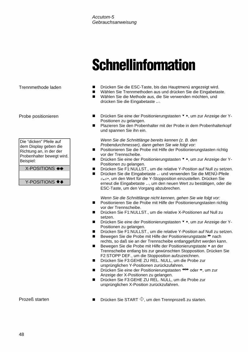
Accutom-5 Gebrauchsanweisung
48
Schnellinformation Drücken Sie die ESC-Taste, bis das Hauptmenü angezeigt wird. Wählen Sie Trennmethoden aus und drücken Sie die Eingabetaste. Wählen Sie die Methode aus, die Sie verwenden möchten, und
drücken Sie die Eingabetaste . Drücken Sie eine der Positionierungstasten , um zur Anzeige der Y-
Positionen zu gelangen. Plazieren Sie den Probenhalter mit der Probe in dem Probenhalterkopf
und spannen Sie ihn ein. Wenn Sie die Schnittlänge bereits kennen (z. B. den
Probendurchmesser), dann gehen Sie wie folgt vor: Positionieren Sie die Probe mit Hilfe der Positionierungstasten richtig
vor der Trennscheibe. Drücken Sie eine der Positionierungstasten , um zur Anzeige der Y-
Positionen zu gelangen. Drücken Sie F1:NULLST., um die relative Y-Position auf Null zu setzen. Drücken Sie die Eingabetaste und verwenden Sie die MENÜ-Pfeile
, um den Wert für die Y-Stopposition einzustellen. Drücken Sie erneut die Eingabetaste , um den neuen Wert zu bestätigen, oder die ESC-Taste, um den Vorgang abzubrechen.
Wenn Sie die Schnittlänge nicht kennen, gehen Sie wie folgt vor: Positionieren Sie die Probe mit Hilfe der Positionierungstasten richtig
vor der Trennscheibe. Drücken Sie F1:NULLST., um die relative X-Positionen auf Null zu
setzen. Drücken Sie eine der Positionierungstasten , um zur Anzeige der Y-
Positionen zu gelangen. Drücken Sie F1:NULLST., um die relative Y-Position auf Null zu setzen. Bewegen Sie die Probe mit Hilfe der Positionierungstaste nach
rechts, so daß sie an der Trennscheibe entlanggeführt werden kann. Bewegen Sie die Probe mit Hilfe der Positionierungstaste an der
Trennscheibe entlang bis zur gewünschten Stopposition. Drücken Sie F2:STOPP DEF., um die Stopposition aufzuzeichnen.
Drücken Sie F3:GEHE ZU REL. NULL, um die Probe zur ursprünglichen Y-Positionen zurückzufahren.
Drücken Sie eine der Positionierungstasten oder , um zur Anzeige der X-Positionen zu gelangen.
Drücken Sie F3:GEHE ZU REL. NULL, um die Probe zur ursprünglichen X-Position zurückzufahren.
Drücken Sie START , um den Trennprozeß zu starten.
Trennmethode laden
Probe positionieren
Prozeß starten
Die “dicken” Pfeile auf dem Display geben die Richtung an, in der der Probenhalter bewegt wird. Beispiel:
X-POSITIONS
Y-POSITIONS

Accutom-5Mode d’emploi
Mode d’emploi no.: 14947001
Date de parution 15.11.2012

Accutom-5 Mode d'emploi
Table des matières Page Guide de l'utilisateur ................................................... 1Guide de Référence .................................................. 25Référence rapide ...................................................... 47
Toujours mentionner le n° de série et la tension/fréquence de l'appareil lors de questions techniques ou de commandes de pièces détachées. Vous trouverez le n° de série et la tension de l'appareil indiqués soit sur la page de garde du mode d'emploi, soit sur une étiquette collée ci-dessous. En cas de doute, veuillez consulter la plaque signalétique de la machine elle-même. La date et le n° de l'article du mode d'emploi peuvent également vous être demandés. Ces renseignements se trouvent sur la page de garde. Les restrictions suivantes doivent être observées. Le non respect de ces restrictions pourra entraîner une annulation des obligations légales de Struers: Mode d'emploi: Le mode d'emploi Struers ne peut être utilisé que pour l'équipement Struers pour lequel il a été spécifiquement rédigé. Manuels de maintenance: Un manuel de service de Struers ne peut être utilisé que par un technicien spécialiste autorisé par Struers. Le manuel de service ne peut être utilisé que pour l'équipement Struers pour lequel il a été spécifiquement rédigé. Struers ne sera pas tenu responsable des conséquences d'éventuelles erreurs pouvant se trouver dans le texte du mode d'emploi/illustrations. Les informations contenues dans ce mode d'emploi pourront subir des modifications ou des changements sans aucun avis préalable. Certains accessoires ou pièces détachées ne faisant pas partie de la présente version de l'équipement peuvent cependant être mentionnés dans le mode d'emploi. Instructions d’origine. Le contenu de ce mode d'emploi est la propriété de Struers. Toute reproduction de ce mode d'emploi, même partielle, nécessite l'autorisation écrite de Struers. Tous droits réservés. © Struers 2012. Struers A/S Pederstrupvej 84 DK-2750 Ballerup Danemark Téléphone +45 44 600 800 Téléfax +45 44 600 801

Accutom-5 Mode d'emploi
Accutom-5 Feuille de sécurité
A lire attentivement avant utilisation 1. L'opérateur doit être parfaitement instruit dans l'utilisation de la
machine, ses meules de tronçonnage selon le Mode d'emploi et les instructions des meules de tronçonnage.
2. La machine doit être placée sur une table sûre et stable.
3. S'assurer que la tension utilisée corresponde à la tension indiquée au dos de la machine. La machine doit être mise à la terre.
4. Les meules de tronçonnage utilisées doivent être intactes. Les meules de tronçonnage doivent être homologuées pour 3000 t/m. Si d'autres meules de tronçonnage ou scies sont utilisées, s'assurer que le réglage de la vitesse sur Accutom-5 ne dépasse pas la vitesse max. permise pour les meules de tronçonnage ou scies en question.
5. Respecter les règles de sécurité en vigueur pour la manipulation, le mélange, le remplissage, le vidage et l'élimination de l'additif pour le liquide de refroidissement.
6. L'échantillon doit être correctement bridé dans le porte-échantillons.
7. Ne pas toucher l'échantillon, la tête du porte-échantillons, la meule de tronçonnage lors du positionnement de l'échantillon à l'aide des touches de contrôle POSITION.
8. Ne jamais essayer d'ouvrir le couvercle avant l'arrêt complet de la meule de tronçonnage.
L’équipement ne devra servir qu’à l’usage auquel il est destiné et ainsi que décrit en détails dans le Mode d’emploi. La machine est conçue pour être utilisée avec des articles consommables fournis par Struers. En cas de mauvais usage, d'installation incorrecte, de modification, de négligence, d'accident ou de réparation impropre, Struers n'acceptera aucune responsabilité pour les dommages causés à l'utilisateur ou à la machine. Le démontage d'une pièce quelconque de la machine, en cas d'entretien ou de réparation, doit toujours être assuré par un technicien qualifié (en électro-mécanique, électronique, mécanique, pneumatique, etc.).

Accutom-5 Mode d'emploi
Élimination Les équipements marqués d’un symbole WEEE contiennent des composants électriques et électroniques et ne doivent pas être jetés avec les ordures ménagères. Veuillez contacter les autorités locales pour toutes informations sur la procédure correcte d’élimination à suivre selon la législation nationale.

Accutom-5 Mode d'emploi
1
Guide de l'utilisateur Table des matières Page
1. Installation 3Vérifier le contenu de l'emballage ...................................................... 3Placer Accutom-5 ............................................................................... 3Se familiariser avec Accutom-5 .......................................................... 3Alimentation en courant ..................................................................... 4
Changer les réglages du courant .............................................. 4Unité de recyclage ............................................................................. 6Programmation du logiciel .................................................................. 7
Menu de Configuration .............................................................. 7Choisir la langue ....................................................................... 8
2. Opérations de base 9Utilisation des touches de contrôle .................................................... 9
Touches de contrôle d'Accutom-5 ............................................ 9Groupes de fonctions ................................................................ 9Signaux sonores ....................................................................... 9Emplacement de l'interrupteur principal .................................... 9
Touches du panneau frontal ............................................................ 10Affichage ................................................................................. 11
Lecture de l'affichage ....................................................................... 12Changer/Editer les valeurs ............................................................... 13
Valeurs numériques ................................................................ 13Valeurs alphanumériques ....................................................... 14
Positionner l'échantillon .................................................................... 15Position de référence .............................................................. 15Position absolue ...................................................................... 15Position relative ....................................................................... 15Zéro relatif ............................................................................... 15Position d'arrêt ........................................................................ 15
Tronçonnage .................................................................................... 16Changer la meule de tronçonnage .......................................... 16Brider l'échantillon et le porte-échantillons ............................. 17Positionner l'échantillon .......................................................... 17
Programmer les paramètres de tronçonnage ................................... 18Meule ...................................................................................... 18Vitesse .................................................................................... 18Avance .................................................................................... 18Force ....................................................................................... 18Rotation ................................................................................... 19Eau de refroidissement ........................................................... 19

Accutom-5 Mode d'emploi
2
Commencer le tronçonnage ............................................................. 19 Pendant le tronçonnage ................................................................... 20
Changement de la vitesse d’avance ...................................... 20Rétracter l'échantillon ............................................................. 20Limite de force atteinte ............................................................ 20
Arrêter le tronçonnage ..................................................................... 21Arrêt automatique ................................................................... 21Arrêt manuel ........................................................................... 21
3. Maintenance Quotidienne ...................................................................................... 22
Vérifier l’unité de recyclage ..................................................... 22Hebdomadaire .................................................................................. 23Remplir le réservoir d'eau de recyclage ........................................... 23
Vidange et nettoyage du réservoir .......................................... 23Remplir le réservoir ................................................................. 23
Maintenance des meules de tronçonnage ....................................... 24Maintenance des meules diamantées et CBN ........................ 24Rangement des meules de tronçonnage abrasives ................ 24

Accutom-5 Mode d'emploi
3
1. Installation Dans la caisse de transport se trouvent les pièces suivantes: 1 Accutom-5 1 Câble électrique 1 Porte-échantillons avec mors parallèles 1 Flasque pour meule de tronçonnage (42 mm de diam.) 1 Tige d'arrêt 1 Clé (17 mm) 1 Petite grille 1 Grande grille 1 Clé hexagonale, 2 mm 1 Clé hexagonale, 2,5 mm 1 Clé hexagonale 3 mm 1 Clé hexagonale 4 mm 1 Clé hexagonale 5 mm 2 Vis M4x20 2 Vis M4x35 1 Jeu de Modes d'emploi Accutom-5 doit être placée sur une table stable et plane (tolérance ±1 mm). La table doit pouvoir porter un poids de 50 kg min. Prendre le temps de se familiariser avec l'emplacement et les noms des composants d'Accutom-5.
A Panneau frontal/Touche(s) du panneau frontal B Interrupteur principal C Unité de recyclage D Meule de tronçonnage E Tête du porte-échantillons
Vérifier le contenu de l'emballage
Placer Accutom-5
Se familiariser avec Accutom-5

Accutom-5 Mode d'emploi
4
Toujours se rappeler de couper le courant lors de l’installation de l’équipement électrique.
Le réglage standard d’Accutom-5 est 240V.
Tirer le porte-fusible de la tête de câble au dos de la machine. Tirer l’interrupteur de courant et le faire tourner pour le régler
correctement.
Courant requis Réglage 230 ou 240V 240V 200 à 220V 200V
Noter: les deux réglages supplémentaires, 110V et 120V ne doivent pas être utilisés.
Réinsérer l’interrupteur. Remettre le porte-fusible dans la tête de câble.
Alimentation en courant
IMPORTANT Vérifier que le courant utilisé correspond bien au courant indiqué sur la
plaque au dos de la machine.
Changer les réglages du courant
Si les réglages à l'usine ne correspondent pas à la tension du réseau, le réglage peut être modifié de 240V à 220V:

Accutom-5 Mode d'emploi
5
Accutom-5 est livrée avec 2 types de câbles électriques : La prise à 2 tiges (Schuko européenne) est pour une utilisation monophasée. Si la prise fournie sur ce câble n’est pas autorisée dans le pays d’utilisation, celle-ci devra être remplacée par une prise homologuée. Les fils électriques devront être branchés comme suit : Jaune/vert : terre Marron: ligne (sous courant) Bleu: neutre La prise à 3 tiges (NEMA des Etats-Unis) est pour une utilisation à 3 phases. Si la prise fournie sur ce câble n’est pas autorisée dans le pays d’utilisation, celle-ci devra être remplacée par une prise homologuée. Les fils électriques devront être branchés comme suit: Vert: terre Noir: ligne (sous courant) Blanc: ligne (sous courant) L’autre extrémité des deux câbles est équipée d’un connecteur de câble IEC 320 à connecter à Accutom.
Alimentation monophasée
Alimentation à 3 phases
Branchement à la machine
ATTENTION ! Le courant de sortie de ce câble est 200 – 240V et non 110V.
NE PAS utiliser ce câble pour connecter un équipement utilisant une alimentation en courant de 110V. Une telle erreur pourrait provoquer des
dommages matériels.

Accutom-5 Mode d'emploi
6
Sortir le réservoir de recyclage. Remplir le réservoir de 3,88 l d’eau additionnée de 120 ml
d’additif Struers. Le niveau d'eau doit être d'au minimum 5 mm au dessous du bord de l'orifice frontal du couvercle du réservoir.
Vérifier que le couvercle soit bien fixé sur le réservoir de
recyclage et pousser le tiroir avec le réservoir de recyclage pour le remettre en place.
Vérifier que l’extrémité du tube d’arrivée tombe en bonne position.
Unité de recyclage
IMPORTANT Toujours s’assurer qu’il y a suffisamment d’eau dans le réservoir, car la
pompe de recyclage serait endommagée si elle fonctionne à sec.
Noter: L'eau de refroidissement doit être remplacée au moins une fois par mois.
IMPORTANT Toujours maintenir la concentration correcte d'additif Struers dans l'eau de
refroidissement (pourcentage indiqué sur la bouteille d'additif). Se rappeler d'ajouter l'additif Struers à chaque remplissage d'eau.
Ne pas utiliser d'huile, pétrole, ou autres additifs à base de térébenthine, uniquement l’additif Struers.

Accutom-5 Mode d'emploi
7
Allumer le courant à l'interrupteur principal se trouvant au dos de la machine. L'affichage suivant apparaîtra brièvement:
Ensuite l'affichage retournera à l'écran qui était montré avant d'éteindre Accutom-5, généralement une méthode de tronçonnage. Lorsqu'Accutom-5 est allumée pour la première fois, l'affichage qui apparaît doit être MENU PRINCIPAL. Si l'entête de l'affichage est différente, appuyer sur ESC, jusqu'à ce que MENU PRINCIPAL apparaisse. (Un bip long peut être entendu). Le MENU PRINCIPAL est le niveau le plus élevé dans la structure de menus. A partir de là, il est possible de se déplacer dans une configuration, des fonctions manuelles et des méthodes de tronçonnage.
MENU PRINCIPAL METHODES DE TRONÇONNAGE FONCTIONS MANUELLES CONFIGURATION
Appuyer sur MENU VERS LE HAUT/LE BAS
pour choisir CONFIGURATION.
Appuyer sur ENTER pour activer le menu CONFIGURATION.
CONFIGURATION MEULES DE TRONÇONNAGE OPTIONS
Programmation du logiciel Menu de Configuration
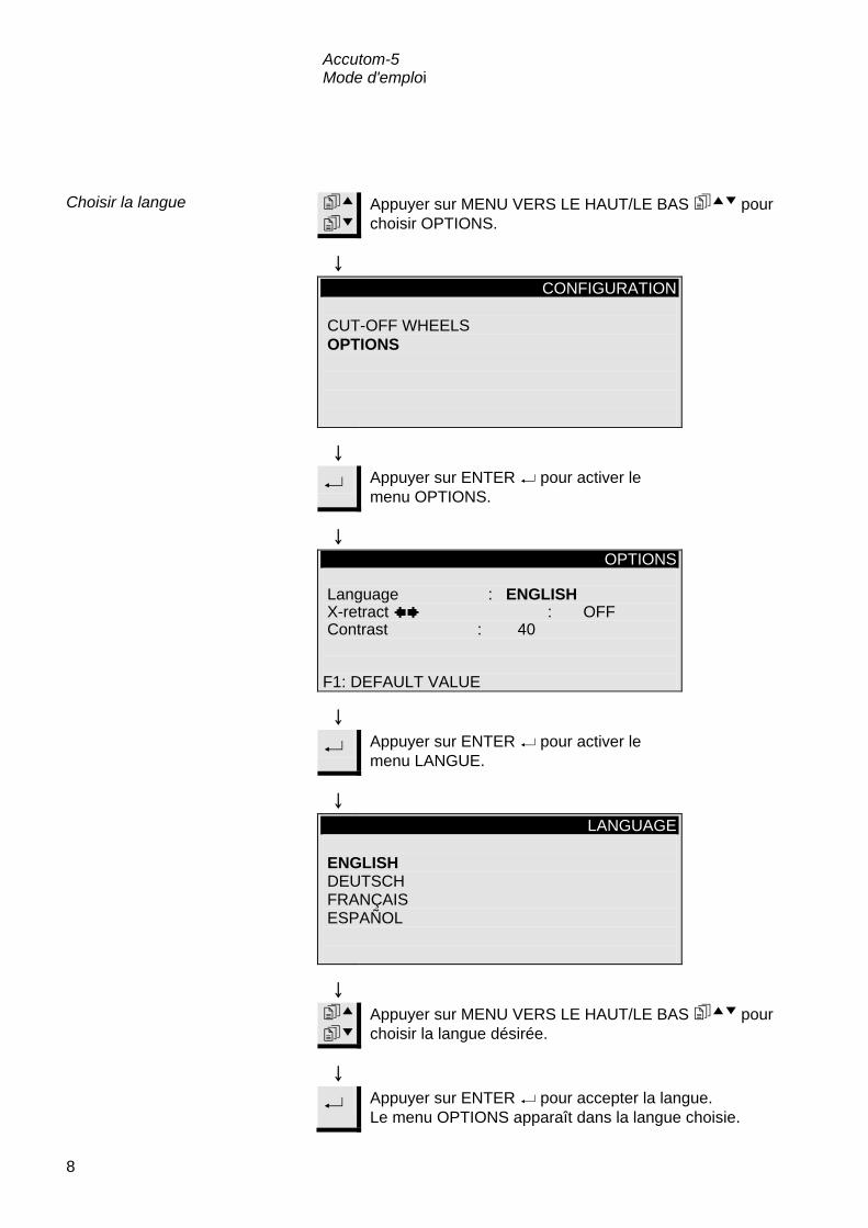
Accutom-5 Mode d'emploi
8
Appuyer sur MENU VERS LE HAUT/LE BAS
pour choisir OPTIONS.
CONFIGURATION CUT-OFF WHEELS OPTIONS
Appuyer sur ENTER pour activer le menu OPTIONS.
OPTIONS Language : ENGLISH X-retract Contrast : 40
: OFF
F1: DEFAULT VALUE
Appuyer sur ENTER pour activer le menu LANGUE.
LANGUAGE ENGLISH DEUTSCH FRANÇAIS ESPAÑOL
Appuyer sur MENU VERS LE HAUT/LE BAS
pour choisir la langue désirée.
Appuyer sur ENTER
Choisir la langue
pour accepter la langue. Le menu OPTIONS apparaît dans la langue choisie.
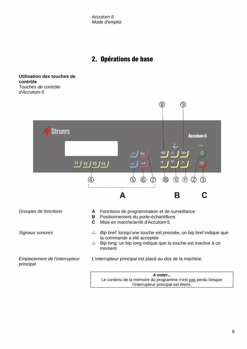
Accutom-5 Mode d'emploi
9
2. Opérations de base
A Fonctions de programmation et de surveillance B Positionnement du porte-échantillons C Mise en marche/arrêt d'Accutom-5 Bip bref: lorsqu'une touche est pressée, un bip bref indique que
la commande a été acceptée Bip long: un bip long indique que la touche est inactive à ce
moment L'interrupteur principal est placé au dos de la machine.
Utilisation des touches de contrôle Touches de contrôle d'Accutom-5
Groupes de fonctions
Signaux sonores
Emplacement de l'interrupteur principal
A noter... Le contenu de la mémoire du programme n'est pas perdu lorsque
l'interrupteur principal est éteint.

Accutom-5 Mode d'emploi
10
Nom Touche Fonction Nom Touche Fonction
INTERRUP-TEUR PRINCIPAL
L'interrupteur principal est placé au dos de la machine.
ESC
Esc Pour quitter le présent menu ou l'écran de position du porte-échantillons
MARCHE
Commence le processus de tronçonnage selon la méthode pré-programmée. L'eau de recyclage, si choisie, est activée.
POSITION GAUCHE RAPIDE
Se déplace au menu POSITION ou déplace le porte-échantillons vers la gauche en direction X en échelons de 100 µm. Presser continûment la touche pour augmenter la vitesse.
ARRET
Interrompt le processus de tronçonnage. L'eau de recyclage, si choisie, est désactivée.
POSITION DROITE RAPIDE
Se déplace au menu POSITION ou déplace le porte-échantillons vers la droite en direction X en échelons de 100 µm. Presser continûment la touche pour augmenter la vitesse.
TOUCHES DE FONCTION
F1/F2 F3/F4
Touches de contrôle à usages divers. Voir au bas de chaque écran.
POSITION GAUCHE
Se déplace au menu POSITION ou déplace le porte-échantillons lentement vers la gauche en direction X en échelons de 5 µm. Presser continûment la touche pour augmenter la vitesse.
MENU
Se déplace vers le haut () ou le bas () dans le menu arborescent d'Accutom-5. Lorsqu'un paramètre est programmé, la valeur est augmentée () ou diminuée (
).
POSITION DROITE
Se déplace au menu POSITION ou déplace le porte-échantillons lentement vers la droite en direction X en échelons de 5 µm. Presser continument la touche pour augmenter la vitesse.
RETOUR
Pour choisir une valeur de paramètre marquée ou un menu.
POSITION VERS LE
HAUT/LE BAS
/
Se déplace au menu POSITION ou déplace le porte-échantillons vers le haut ou le bas en direction Y en échelons de 100 µm. Presser continûment la touche pour augmenter la vitesse.
Touches du panneau frontal

Accutom-5 Mode d'emploi
11
CHOIX DE METHODE DE TRONÇONNAGE A 1.METHODE VIDE 2.METHODE VIDE 3.METHODE VIDE 4.METHODE VIDE 5.METHODE VIDE 6.METHODE VIDE 7.METHODE VIDE 8.METHODE VIDE 9.METHODE VIDE 10.METHODE VIDE 11.METHODE VIDE 12.METHODE VIDE F1:COPIER F2:INSERER F3:EFFACER
A Entête B Texte clignotant. Marqueur C Options touches de contrôle D Flèche indiquant qu'il y a d'autres lignes dans l'image
Affichage
A Noter Les exemples d'affichage dans ce Mode d'emploi montrent un nombre
possible de textes. L'affichage visible peut différer des exemples se trouvant dans ce Mode d'emploi.
B
C
A D

Accutom-5 Mode d'emploi
12
L'affichage peut montrer différentes sortes d'informations, par exemple sur la méthode de tronçonnage ou sur la position de l'échantillon. Un écran pour une méthode tronçonnage pourrait ressembler à l'exemple suivant: Méthode tronç.: 1. METHODE VIDE Meule : B0D15 Vitesse : 2700 t/m Avance :0.100 mm/s Limite f.: MOYENNE Rotation: OFF Eau : ON
Appuyer sur l'une des touches de positionnement sur l'axe X et l'écran apparaît comme suit:
POSITIONS X Position absolue: 15.255 mm Position relative: 5.000 mm F1:A ZERO F2:AJOUTER F3:A ZERO RELATIF
Appuyer sur l'une des touches de positionnement sur l'axe Y et l'écran apparaît comme suit:
POSITIONS Y Position absolue: 55.7 mm Position relative: 0.0 mm Position arrêt: 20.0 mm F1:A ZERO F2:ARRET F3:A ZERO RELATIF
Esc Appuyer sur ESC pour revenir à l'écran de la méthode de tronçonnage.
Lecture de l'affichage
Les flèches près du titre Positions indiquent la direction dans laquelle le porte-échantillons est déplacé, par exemple:
POSITIONS X
POSITIONS Y

Accutom-5 Mode d'emploi
13
Selon le type de valeur, il y a deux différentes façons d'éditer. Méthode tronç.: 1. METHODE VIDE Meule : B0D15 Vitesse : 2700 t/m Avance :0.100 mm/s Limite f.: MOYENNE Rotation: OFF Eau : ON
D
mO mN
Appuyer sur MENU VERS LE HAUT/LE BAS mON pour choisir la valeur numérique à changer, par ex. Avance:
D Méthode tronç.: 1. METHODE VIDE Meule : B0D15 Vitesse : 2700 t/m Avance :0.100 mm/s Limite f.: MOYENNE Rotation: OFF Eau : ON
D
e Appuyer sur ENTER e, pour éditer la valeur.
D Deux crochets [ ] apparaissent autour de la valeur.
Méthode tronç.: 1. METHODE VIDE Meule : B0D15 Vitesse : 2700 t/m Avance [0.100]mm/s Limite f.: MOYENNE Rotation: OFF Eau : ON
D
mO mN
Appuyer sur MENU VERS LE HAUT/LE BAS mON pour augmenter ou diminuer la valeur numérique.
D
e Appuyer sur ENTER e, pour accepter la nouvelle valeur.
D ou
Esc Appuyer sur ESC pour garder la valeur originale.
Changer/Editer les valeurs
Valeurs numériques

Accutom-5 Mode d'emploi
14
Méthode tronç.: 1. METHODE VIDE Meule : B0D15 Vitesse : 2700 t/m Avance :0.100 mm/s Limite f.: MOYENNE Rotation: OFF Eau : ON
Appuyer sur MENU VERS LE HAUT/LE BAS
pour choisir la valeur alphanumérique à changer, par ex. MEULE DE TRONÇONNAGE.
Appuyer sur ENTER
, pour éditer la valeur.
Un sous-menu apparaît.
MEULES DE TRONÇONNAGE M0D08 M1D08 M0D10 M1D10 M0D13 M1D13 B0D13 B0C13 50A13 30A13 SAW13 M0D15 M1D15 E0D15 B0D15 B0C15 50A15 40A15 10S15 30A15 UTIL 1 UTIL 2 UTIL 3 UTIL 4 UTIL 5 UTIL 6 UTIL 7 UTIL 8 UTIL 9 UTIL10
Appuyer sur MENU VERS LE HAUT/LE BAS
pour choisir la meule de tronçonnage correcte.
Appuyer sur ENTER
, pour accepter la nouvelle valeur et retourner à l'écran précédent.
ou
Esc Appuyer sur ESC pour garder la valeur originale et pour retourner à l'écran précédent.
Valeurs alphanumériques
Accutom-5 Mode d'emploi
15
Après le bridage de l'échantillon dans le porte-échantillons, celui-ci est placé dans la tête du porte-échantillons où il est fixé. Pour déplacer le porte-échantillons et l'échantillon, les touches POSITION sont utilisées. L'affichage montre la position en direction X ou Y. A chaque fois que le courant est allumé alors que le couvercle est fermé, Accutom-5 vérifie sa propre position de référence. La tête du porte-échantillons sera éloignée autant que possible, à la position de référence (X=0.000 Y=0.0), et retournera ensuite à la position où elle était avant que le courant ne soit allumé. La position absolue montre la distance totale que le porte-échantillons a parcourue à partir de sa position de référence. La position relative est égale à celle de la position absolue jusqu'à ce qu'elle soit mise à zéro à un point désiré. En la mettant à zéro, le calcul du mouvement de l'échantillon près de la meule de tronçonnage est facilité. La valeur de l'écran est toujours en rapport à la distance que le porte-échantillons a parcouru depuis qu'il a été mis à zéro. La position zéro relatif est le point où la position relative en position X ou Y a été mise à zéro. Le processus de tronçonnage achevé, le porte-échantillons retourne automatiquement à ce point. Appuyer sur F3 dans l'écran de position X ou Y permet également de faire revenir l'échantillon en position zéro relatif. Une position d'arrêt peut être programmée pour interrompre le processus de tronçonnage à un point précis. Après avoir atteint ce point, l'échantillon va se retirer et retourner à la position zéro relatif. En réglant la position d'arrêt, s'assurer de compenser une usure possible de la meule de tronçonnage. Ceci est particulièrement important lors de l'usage de meules Al2O3
ou SiC.
Positionner l'échantillon
Position de référence
Position absolue
Position relative
Zéro relatif
Position d'arrêt
Compenser l'usure de la meule

Accutom-5 Mode d'emploi
16
Ouvrir le couvercle et faire basculer vers le haut le tube de refroidissement de droite.
Insérer la tige d'arrêt dans l'orifice du flasque interne. Utiliser la clé (17 mm) pour desserrer la vis du flasque. Retirer le flasque externe et la meule.
Monter la nouvelle meule de tronçonnage et remonter le flasque
externe, avec la partie usinée, tournée vers le flasque interne. Insérer la tige de fermeture dans l'orifice du flasque interne. Fixer légèrement la vis du flasque à l'aide de clé. Remettre en place le tube de refroidissement de droite.
Tronçonnage Changer la meule de tronçonnage
IMPORTANT La tolérance entre la broche et le flasque interne est très mince ce qui
signifie que les deux surfaces doivent être absolument propres. Ne jamais essayer de presser la meule de tronçonnage, car ceci pourrait endommager la broche. S'il y a quelques petites barbures, les éliminer à l'aide d'un papier
de prépolissage (granulométrie 1200).
Clé à douille
Tige d'arrêt
Tube derefroidissementavec prise

Accutom-5 Mode d'emploi
17
Brider fermement l'échantillon dans le porte-échantillons à l'aide de la clé hexagonale.
Fixer le porte-échantillons dans la tête du porte-échantillons en poussant le porte-échantillons dans la fixation en queue d'aronde et en serrant la vis à l'aide d'une clé hexagonale.
Lors du tronçonnage par rotation ou par oscillation, l'échantillon et le porte-échantillons doivent être bridés en conséquence pour pouvoir tourner uniformément autour du centre de l'échantillon. Ainsi, le tronçonnage le plus rapide est obtenu, car la meule de tronçonnage tronçonnera la plupart du temps et le risque d'endommagement de la meule sera limité.
Déplacer l'échantillon dans la position de départ correcte, proche
de la meule de tronçonnage à l'aide des touches POSITION. Reprogrammer la position relative en direction X et Y en
appuyant sur F1 dans les écrans respectifs. Programmer la position d'arrêt pour définir la longueur de la
coupe: Il y a deux façons de programmer la position d'arrêt: 1. Si la taille de l'échantillon est connue:
− Appuyer sur ENTER et utiliser MENU VERS LE HAUT/LE BAS
− Appuyer de nouveau sur ENTER pour accepter la valeur ou sur ESC pour annuler.
pour programmer la valeur d'arrêt.
2. Si la taille exacte de l'échantillon n'est pas connue:
− Positionner l'échantillon à l'aide de la touche POSITION pour le déplacer le long de la meule de tronçonnage.
− Déplacer l'échantillon le long de la meule de tronçonnage à la position d'arrêt requise à l'aide de la touche POSITION .
− Appuyer sur F2:ARRET pour enregistrer la position d'arrêt. − Appuyer sur F3:A ZERO RELATIF pour replacer
l'échantillon en position initiale. − Positionner l'échantillon correctement en face de la meule
de tronçonnage à l'aide de la touche POSITION . Si possible, utiliser F3: A ZERO RELATIF.
Brider l'échantillon et le porte-échantillons
Positionner l'échantillon

Accutom-5 Mode d'emploi
18
Tous les paramètres de tronçonnage peuvent être édités indépendamment l'un de l'autre. Voir le paragraphe Changer/Editer valeurs pour plus de détails sur comment changer les valeurs. Méthode tronç.: 1. METHODE VIDE Meule : B0D15 Vitesse : 2700 t/m Avance :0.100 mm/s Limite f.: MOYENNE Rotation: CONT. Vitesse: 3 Sens: > < Eau : ON F3:Rot. TEST F4:SAUVER Toutes les meules de tronçonnage Struers sont listées avec leur valeur de référence pour la limite de force, l'épaisseur de la meule et la vitesse. Sont également inclues huit meules non-définies pour le propre choix de meules de tronçonnage du client (Voir également Configuration de meules de tronçonnage). La vitesse de la meule de tronçonnage peut être réglée entre 300 et 3000 t/m en échelons de 100 t/m. Les valeurs de référence pour toutes les meules de tronçonnage Struers sont déjà sauvegardées avec les définitions de meules. Dès qu'une meule de tronçonnage différente est choisie, la vitesse recommandée est automatiquement insérée. La vitesse d'avance peut être réglée entre 0,005 mm/s et 3,000 mm/s. (Voir le paragraphe Paramètres de tronçonnage au chapitre 3. Consommables pour les réglages recommandés). La limite de force est une protection pour la meule de tronçonnage et/ou les échantillons à tronçonner. Selon l'épaisseur ou la résistance des meules de tronçonnage, la limite de force peut être programmée à trois niveaux différents, BASSE, MOYENNE et ELEVEE. Les valeurs de référence pour toutes les meules de tronçonnage Struers sont déjà gardées en mémoire avec les définitions des meules. Dès qu'une meule de tronçonnage différente est choisie, la limite de force recommandée est automatiquement insérée.
Programmer les paramètres de tronçonnage
Méthode Ecran
Meule
Vitesse
Avance
Force

Accutom-5 Mode d'emploi
19
La rotation peut se révéler un avantage lors du tronçonnage des échantillons grands, très durs, revêtus ou très longs. Sur Accutom-5, trois programmations différentes sont possibles. L'échantillon ne tourne pas. L'échantillon tourne autour de son centre. La vitesse peut être réglée sur trois niveaux différents: 1, 2 ou 3. Le sens de rotation peut être programmé sur soit contre-rotation, soit rotation. Contre-rotation est recommandée. Appuyer sur F3 pour tester la rotation de l'échantillon avec les paramètres programmés. L'échantillon se balance/oscille autour de son centre. La vitesse peut être réglée sur trois niveaux différents: 1, 2 ou 3. L'angle peut être réglé de 10° à 400°. Appuyer sur F3 pour tester la rotation de l'échantillon avec les paramètres programmés.
L'eau de refroidissement peut être réglée soit sur On, soit sur Off. Pour toutes les opérations de tronçonnage normales, le réglage doit être sur On. Avant de commencer le tronçonnage, s'assurer que le compartiment de tronçonnage soit propre pour permettre un débit d'eau de refroidissement régulier. Positionner l'échantillon correctement. Programmer les paramètres de tronçonnage corrects. S'assurer que la meule de tronçonnage correcte est montée. Fermer le couvercle de la machine. Appuyer sur MARCHE
.
Rotation Seulement pour Accutom-5 avec rotation
Rotation: Off
Rotation: Continue
Rotation: Oscillation
Noter Lorsque l'échantillon est déplacé en direction X ou Y , avec la fonction
Rotation réglée sur Cont. ou Osc. un message d'avertissement, “Mode rotation !”, clignotera brièvement sur l'écran pour rappeler à
l'utilisateur que le mode rotation a été choisi.
Eau de refroidissement
Commencer le tronçonnage
Rotation Contre-rotation

Accutom-5 Mode d'emploi
20
Après avoir appuyer sur Marche, un nouvel affichage apparaît: Vitesse d’avance TRONÇONNAGE COMMENCE 0% 100% Vitesse d’avance préprog. : 0.100 mm/s Vitesse d’avance actuelle : 0.100 mm/s Temps du processus restant: 3 min Les vitesses d'avance préprogrammée et actuelle sont affichées. La barre horizontale est utilisée pour affichée la vitesse d’avance de façon graphique. Lors du processus de tronçonnage, la vitesse d'avance peut être changée. Il suffit d'appuyer sur ENTER et de régler la vitesse d'avance à la valeur correcte. Appuyer de nouveau sur ENTER pour confirmer le changement ou sur ESC pour annuler. La seule possibilité de déplacement de l'échantillon une fois que le processus de tronçonnage est commencé est de faire se rétracter l'échantillon de la meule de tronçonnage. Ceci est possible en appuyant sur la touche POSITION VERS LE BAS . Le mouvement vers l'avant de l'échantillon est interrompu et l'échantillon est déplacé vers l'arrière jusqu'à ce que la touche soit de nouveau relâchée. Alors, l'échantillon recommence de nouveau à se déplacer vers l'avant à la vitesse d'avance préprogrammée. Si la vitesse d'avance préprogrammée ne peut pas être obtenue parce que la limite de force est atteinte, Accutom-5 réduit automatiquement la vitesse d'avance à la vitesse maximale possible. Cette valeur est affichée, et une fois la coupe achevée, le message suivant apparaît sur l'affichage:
TRONÇONNAGE FINI
Limite force atteinte pendant tronç. vitesse d'avance réduite à:
0.070 mm/sec
Pour les échantillons similaires à tronçonner par la suite, la vitesse d'avance doit être réduite à la nouvelle valeur ou plus bas.
Pendant le tronçonnage
Changement de la vitesse d’avance
Rétracter l'échantillon
Limite de force atteinte

Accutom-5 Mode d'emploi
21
Accutom-5 interrompt automatiquement le processus de
tronçonnage à la position d'arrêt pré-programmée. (Se rappeler d'assurer la compensation d'une usure possible de la meule lors du réglage de la position d'arrêt).
L'échantillon est alors rétracté et la meule de tronçonnage est arrêtée.
Le processus de tronçonnage peut être interrompu à n'importe
quel moment pendant l'opération en appuyant sur la touche ARRET
Pour éviter d'interrompre le processus alors que la meule de tronçonnage se trouve toujours dans l'échantillon, appuyer sur la touche POSITION pour la direction Y, puis appuyer sur F2: ARRET. L'échantillon se rétracte immédiatement et le processus sera interrompu lorsque la position du zéro relatif est atteinte.
. L'échantillon reste dans sa position actuelle et le processus s'arrête là.
L'affichage revient à ce qu'il était avant le début du tronçonnage.
Arrêter le tronçonnage Arrêt automatique
Arrêt manuel

Accutom-5 Mode d'emploi
22
3. Maintenance Nettoyer le compartiment de tronçonnage à l'aide d'un chiffon
humide. Ne pas utiliser d'eau du robinet, car il y aurait un risque de trop-plein dans le réservoir d'eau de recyclage. Se rappeler d'éliminer de la grille toutes les particules de salissures.
Nettoyer la tête du porte-échantillons et les dispositifs de fermeture de la queue d'aronde.
Nettoyer les flasques. Nettoyer le couvercle transparent à l'aide d'un chiffon humide.
L’eau de refroidissement dans l’unité de recyclage doit être vérifiée après 8 heures d’utilisation ou au moins chaque semaine. L’unité doit être remplie si la pompe de rinçage ne parvient plus à atteindre l’eau de refroidissement. Ne pas oublier d’ajouter l’additif pour liquide de refroidissement de Struers: Une part d’additif pour 33 parts d’eau. Pour vérifier la concentration d’additif, utiliser un réfractomètre. Concentration = valeur Brix. La concentration d’additif devra toujours se trouver entre 2,7 et 3,3 %. Ajouter l’additif pour liquide de refroidissement de Struers si la concentration est trop faible.
Quotidienne
ATTENTION! Ne pas utiliser d'alcool, d'acétone ou autres détergents similaires.
Vérifier l’unité de recyclage
IMPORTANT Toujours maintenir la concentration correcte d'additif Struers dans l'eau de
refroidissement (pourcentage indiqué sur la bouteille d'additif). Se rappeler d'ajouter l'additif Struers à chaque remplissage d'eau.
Ne pas utiliser d'huile, pétrole, ou autres additifs à base de térébenthine, uniquement le additif Struers.

Accutom-5 Mode d'emploi
23
Nettoyer le(s) porte-échantillons: parties amovibles, queues d'aronde et vis. Graisser avec de la graisse exempte d'acide.
Nettoyer le compartiment de tronçonnage et le couvrir correctement. Se rappeler d'éliminer de la grille toutes les particules de salissure.
Remplacer l'eau de refroidissement dans l'unité de recyclage au moins une fois par mois. Tirer doucement le tiroir et abaisser la plaque frontale à
charnières. Sortir précautionneusement le réservoir plat. Retirer la plaque du haut et vider le réservoir à un système
d'écoulement approuvé pour l'élimination des produits chimiques.
Nettoyer le réservoir, les parois de séparation et le couvercle à l'eau du robinet. Placer correctement les parois de séparation dans le réservoir et remettre en place la plaque du haut.
Presser le couvercle dans le réservoir et s'assurer qu'il soit correctement fixé.
Remplir le réservoir de 3,88 l d’eau additionnée de 120 ml
d’additif Struers d’eau. Le niveau d'eau ne doit pas être en dessous de 5 mm du bord de l'orifice frontal du couvercle du réservoir.
Remettre en place le tiroir contenant l'unité de recyclage.
Hebdomadaire
Remplir le réservoir d'eau de recyclage Vidange et nettoyage du réservoir
IMPORTANT Le réservoir et la plaque du haut doivent être placés correctement, sinon la
pompe ne parviendra pas à aspirer l'eau.
IMPORTANT Rincer le système de recyclage à l’eau propre si Accutom n’est pas utilisée pendant des périodes de temps prolongées. Cela empêchera les résidus de
tronçonnage de sécher et d’endommager l’intérieur de la pompe.
Remplir le réservoir
IMPORTANT Toujours s’assurer qu’il y a suffisamment d’eau dans le réservoir, car la
pompe de recyclage serait endommagée si elle fonctionne à sec.
IMPORTANT Toujours maintenir constante la concentration en additif Struers dans l'eau
de recyclage (le pourcentage est indiqué sur la bouteille d'additif). Se rappeler d'ajouter l'additif Struers à chaque remplissage d'eau.

Accutom-5 Mode d'emploi
24
La précision des meules de tronçonnage diamantées et CBN, et donc de la coupe, dépend de la précision avec laquelle les instructions suivantes ont été suivies: Ne jamais exposer la meule de tronçonnage à une surcharge,
telle que surcharge mécanique lourde ou chaleur. Conserver les meules de tronçonnage dans un endroit sec, en
position horizontale sur un support plan, de préférence sous pression légère.
Une meule de tronçonnage propre et sèche ne doit pas corroder. La meule doit donc être nettoyée et séchée avant d'être rangée. Si possible, utiliser des produits de nettoyage ordinaires.
Un dressage régulier de la meule de tronçonnage fait aussi partie de la maintenance générale (voir OPERATIONS AVANCEES).
Ces meules sont sensibles à l'humidité. Il ne faut donc pas mélanger des meules neuves et sèches à des meules humides. Conserver ces meules de tronçonnage dans un endroit sec, en position horizontale sur un support plan.
Maintenance des meules de tronçonnage Maintenance des meules diamantées et CBN
Rangement des meules de tronçonnage abrasives

Accutom-5 Mode d'emploi
25
Guide de Référence Table des matières Page
1. Opérations avancées Menu Configuration .......................................................................... 26
Meules de tronçonnage .......................................................... 27Options .................................................................................... 28
Fonctions manuelles ........................................................................ 29Rotation de l'échantillon .......................................................... 30Pompe de recyclage ............................................................... 31Dressage ................................................................................. 32
Options de méthodes ....................................................................... 34Sauvegarder une Méthode ..................................................... 34Copier une méthode ............................................................... 35Insérer une méthode ............................................................... 36Effacer une méthode ............................................................... 37Editer les noms ....................................................................... 38Nommer les principes d'édition ............................................... 39
2. Accessoires ........................................................................... 40
3. Consommables Meules de tronçonnage .................................................................... 41Optimiser les résultats du tronçonnage ............................................ 41
Paramètres de tronçonnage ................................................... 41Questions sur le tronçonnage courantes ................................ 42
Consommables ................................................................................ 42
4. Indications d'erreurs ........................................................... 43
5. Données techniques ............................................................ 45
6. Structure de Menus ............................................................. 46

Accutom-5 Mode d'emploi
26
1. Opérations avancées Appuyer sur ESC jusqu'à ce que le Menu principal soit atteint. (Un bip long retentit).
MENU PRINCIPAL METHODES DE TRONÇONNAGE FONCTIONES MANUELLES CONFIGURATION
Appuyer sur MENU VERS LE HAUT/LE BAS
pour choisir CONFIGURATION.
Appuyer sur ENTER pour activer le menu CONFIGURATION.
CONFIGURATION MEULES DE TRONÇONNAGE OPTIONS
Menu Configuration

Accutom-5 Mode d'emploi
27
Pour utiliser d'autres meules que les meules de tronçonnage Struers, celles-ci doivent être configurées pour contenir les valeurs correctes de limite de force, d'épaisseur de meule et de vitesse. Pour que l'utilisateur configure ses propres meules de tronçonnage,
Appuyer sur MENU VERS LE HAUT/LE BAS
pour choisir MEULES DE TRONÇONNAGE.
Appuyer sur ENTER
pour activer le menu MEULES DE TRONÇONNAGE.
CONFIGURATION DES MEULES DE TRONÇONNAGE Meule de tronçonnage : UTIL 1 Limite de force : MOYENNE Epaisseur de la meule: 0.50 mm Vitesse de la meule : 3000 t/m F1:MEULE PREC. F2:MEULE SUIV. F4:NOM
Appuyer sur MENU VERS LE HAUT/LE BAS
pour choisir la valeur à changer.
Appuyer sur ENTER
pour éditer la valeur.
Après avoir changer la valeur,
Appuyer sur ENTER
pour accepter la nouvelle valeur et pour retourner à l'écran précédent.
F4 Appuyer sur F4 pour donner un nouveau nom à la meule de tronçonnage. (Pour plus de détails, voir Editer les Noms).
Meules de tronçonnage

Accutom-5 Mode d'emploi
28
Dans le menu d'options, différents articles peuvent être configurés. Voir comment changer de langue à la section Installation de ce Mode d'emploi. Après avoir atteint la position d'arrêt, l'échantillon retourne normalement directement à la position zéro relatif. Pour éviter tout contact avec la meule de tronçonnage pendant ce mouvement, l'échantillon peut être rétracté de la meule avant d'être repositionné en réglant X-rétracte sur ON. Après avoir atteint la position zéro relatif, l'échantillon retourne alors à sa position originale.
Le réglage du contraste sur l’affichage peut être réglé. Une pression de la touche F1 mettra à zéro l’option invertie à la valeur de référence réglée à l’usine.
Options
Langue
X-rétracte
IMPORTANT
S'assurer que la position d'arrêt Y soit correctement programmée. Si l'échantillon n'est pas complètement tronçonné avant que l'échantillon ne
soit rétracté, il est possible que la meule de tronçonnage soit endommagée.
Contraste
F1: VALEUR DE REFERENCE

Accutom-5 Mode d'emploi
29
Sur Accutom-5, plusieurs fonctions peuvent aussi être effectuées manuellement. Toutes ces fonctions sont disponibles au Menu Fonctions manuelles. Appuyer sur ESC jusqu'au Menu principal.
MENU PRINCIPAL METHODES DE TRONÇONNAGE FONCTIONS MANUELLES CONFIGURATION
Appuyer sur MENU VERS LE HAUT/LE BAS
pour choisir FONCTIONS MANUELLES.
Appuyer sur ENTER pour activer le menu FONCTIONS MANUELLES.
MENU DES FONCTIONS MANUELLES ROTATION DE L’ECHANTILLON POMPE DE RECYCLAGE DRESSAGE DE LA MEULE DE TRONÇONNAGE
Fonctions manuelles

Accutom-5 Mode d'emploi
30
Appuyer sur MENU VERS LE HAUT/LE BAS
pour choisir ROTATION ECHANTILLONS.
Appuyer sur ENTER
pour activer le menu ROTATION ECHANTILLONS.
ROTATION DE L’ECHANTILLON Rotation de l’échantillon: CONTINUE Niveau de vitesse : 1 Sens de rotation : > < F1:ROTATION MARCHE
Appuyer sur MENU VERS LE HAUT/LE BAS
pour choisir la valeur à changer.
Appuyer sur ENTER pour éditer la valeur.
Après avoir changé la valeur,
Appuyer sur ENTER
pour accepter la nouvelle valeur et pour retourner à l'écran précédent.
F1 Appuyer sur F1 pour commencer la rotation et vérifier que tout est aligné correctement. Appuyer de nouveau sur F1 pour arrêter la rotation.
Rotation de l'échantillon

Accutom-5 Mode d'emploi
31
A partir du MENU FONCTIONS MANUELLES appuyer sur MENU VERS LE HAUT/BAS
pour choisir la POMPE DE RECYCLAGE.
MENU FONCTIONS MANUELLES ROTATION ECHANTILLONS POMPE RECYCLAGE DRESSAGE MEULE TRONÇONNAGE
Appuyer sur ENTER pour activer l'option POMPE RECYCLAGE.
POMPE RECYCLAGE F1:POMPE MARCHE
F1 Appuyer sur F1 pour mettre en marche la pompe de recyclage. Appuyer sur F1 pour arrêter de nouveau la pompe de recyclage.
Pompe de recyclage

Accutom-5 Mode d'emploi
32
Les meules de tronçonnage diamantées et CBN peuvent avoir besoin d'un dressage pour "acérer" de nouveau la meule et obtenir un effet maximum après le tronçonnage des matériaux ductiles. Pour cela, procéder comme suit: Monter la meule de tronçonnage à dresser. Brider le bâtonnet de dressage dans le porte-échantillons et le
positionner correctement. − Le bâtonnet de dressage doit se trouver en face de la meule
afin que la meule coupe des "tranches" du bâtonnet de dressage.
A partir du MENU FONCTIONS MANUELLES appuyer sur MENU VERS LE HAUT/BAS choisir DRESSAGE MEULE TRONÇONNAGE.
pour
MENU FONCTIONS MANUELLES
ROTATION DE L’ECHANTILLON POMPE RECYCLAGE DRESSAGE DE LA MEULE DE TRONÇONNAGE
Appuyer sur ENTER
pour activer l'option DRESSAGE MEULE TRONÇONNAGE.
Dressage
Dressage des meules de tronçonnage

Accutom-5 Mode d'emploi
33
DRESSAGE DE LA MEULE DE TRONÇONNAGE
Vitesse d’avance : 0.5 mm/s Vitesse de la meule : 3000 t/m Eau de refroidissement : ON Distance Y
: 10.0 mm
F1:DRESSAGE MARCHE
Appuyer sur MENU VERS LE HAUT/LE BAS
pour choisir la valeur à changer.
Appuyer sur ENTER
pour éditer la valeur.
Appuyer sur ENTER
pour accepter la nouvelle valeur et pour retourner à l'écran précédent.
F1 Appuyer sur F1 pour commencer
l'opération de dressage.

Accutom-5 Mode d'emploi
34
En travaillant avec une méthode spécifique, il est possible de garder en mémoire les changements opérés dans la base de données. Dès qu'un paramètre est changé dans une méthode de
tronçonnage, F4:SAUVER apparaîtra au bas de l'affichage. Méthode tronç.: 1. METHODE VIDE Meule : B0D15 Vitesse : 2700 t/m Avance :0.200 mm/s Limite f.: MOYENNE Rotation: OFF Eau : ON F4:SAUVER
F4 Appuyer sur F4:SAUVER pour garder les changements en mémoire après que tous les paramètres nécessaires aient été modifiés.
GARDER EN MEMOIRE D’UNE METHODE Sauver les changements dans la méthode 1. METHODE VIDE ? RETOUR: OUI ESC: NON
Appuyer sur ENTER pour garder en mémoire la méthode modifiée.
Si la méthode n'a pas déjà été nommée, le nom changera automatiquement de METHODE VIDE à METH. NON-NOMMEE. Ceci montrera toujours qu'au moins un paramètre a été changé comparé à une méthode de référence.
Options de méthodes Sauvegarder une Méthode
Important Lorsque des changements sont sauvegardés, la méthode originale sera
automatiquement remplacée. Pour garder la méthode originale, il est nécessaire de faire une copie de la méthode en lui attribuant un nouveau
nom, effectuant ainsi des changements dans une copie plutôt que de changer la méthode originale. Voir Copier une méthode.

Accutom-5 Mode d'emploi
35
Copier une méthode est un raccourci pour créer une nouvelle méthode de tronçonnage en se basant sur une méthode déjà existante. Choisir la méthode de tronçonnage à partir de laquelle copier.
CHOIX METHODE TRONÇONNAGE 1.METH. NON-NOMMEE 2.METHODE VIDE
3.METHODE VIDE 4.METHODE VIDE 5.METHODE VIDE 6.METHODE VIDE 7.METHODE VIDE 8.METHODE VIDE 9.METHODE VIDE 10.METHODE VIDE 11.METHODE VIDE 12.METHODE VIDE F1:COPIER F3:EFFACER F4:NOM
Appuyer sur ENTER pour voir les paramètres de la méthode.
Esc Appuyer sur Esc pour retourner à l'affichage ci-dessus.
F1 Appuyer sur F1:COPIER pour copier la méthode en mémoire.
COPIER UNE METHODE Voulez-vous copier la méthode 1. METH. NON-NOMMEE en mémoire? RETOUR: OUI ESC: NON
Appuyer sur ENTER
pour accepter de copier la méthode en mémoire.
Copier une méthode

Accutom-5 Mode d'emploi
36
Pour insérer une méthode dans une autre méthode:
Appuyer sur MENU VERS LE HAUT/LE BAS
pour choisir la méthode, dans laquelle insérer une méthode.
S'il ne s'agit pas d'une METHODE VIDE: Appuyer sur ENTER pour voir la
méthode.
Esc Appuyer sur Esc pour retourner à l'affichage ci-dessus.
F2 Appuyer sur F2:INSERER pour insérer la méthode à partir de la mémoire.
INSERTION D’UNE METHODE Voulez-vous sauver la mémoire dans 2. METHODE VIDE ? RETOUR: OUI ESC: NON
Appuyer sur ENTER pour accepter l'insertion de la méthode.
Insérer une méthode

Accutom-5 Mode d'emploi
37
Si une méthode n'est plus utile, il faut l'effacer. Les paramètres seront remplacés par les valeurs de référence, pouvant facilement être remplacées par une nouvelle méthode, plus tard. Le nom de la méthode sera remplacé par: METHODE VIDE, indiquant qu'il est possible de copier dans cette méthode, ou de la modifier, sans risquer d'effacer des données de valeur. Choisir la méthode à effacer.
CHOIX DE METHODE DE TRONÇONNAGE 1.METH. NON-NOMMEE 2.METHODE VIDE
3.METHODE VIDE 4.METH. NON-NOMMEE 5.METHODE VIDE 6.METHODE VIDE 7.METHODE VIDE 8.METHODE VIDE 9.METHODE VIDE 10.METHODE VIDE 11.METHODE VIDE 12.METHODE VIDE F1:COPIER F2:INSERER F3:EFFACER F4:NOM
Appuyer sur ENTER
pour voir la méthode et pour s'assurer qu'aucune donnée de valeur ne sera effacée.
Esc Appuyer sur Esc pour retourner à l'affichage ci-dessus.
F3 Appuyer sur F3:EFFACER.
MISE A ZERO D’UNE METHODE Voulez-vous effacer cette méthode ? 4. METH. NON-NOMMEE RETOUR: OUI ESC: NON
Appuyer sur ENTER pour effacer la méthode.
Effacer une méthode

Accutom-5 Mode d'emploi
38
Les noms de méthodes et de meules de tronçonnage peuvent être édités et changés à volonté. Choisir la méthode ou la meule de tronçonnage à nommer.
CHOIX DE METHODE DE TRONÇONNAGE 1.METH. NON-NOMMEE 2.METHODE VIDE
3.METHODE VIDE 4.METH. NON-NOMMEE 5.METHODE VIDE 6.METHODE VIDE 7.METHODE VIDE 8.METHODE VIDE 9.METHODE VIDE 10.METHODE VIDE 11.METHODE VIDE 12.METHODE VIDE F1:COPIER F2:INSERER F3:EFFACER F4:NOM
F4 Appuyer sur F4:NOM.
METH. NON-NOMMEE EDITER LE NOM Texte:METH. NON-NOMMEE App. RETOUR pour accepter le texte, ou appuyer “
“ pour choisir caractère.
F1:GAUCHE F2:ESPACE F3:EFFACER F4:DROITE
Appuyer sur MENU VERS LE BAS: pour parvenir au jeu de caractères.
METH. NON-NOMMEE EDITER LE NOM Texte:METH. NON-NOMMEE ABCDEFGHIJKLMNOPQRSTUVWXYZ 0123456789,.;:-!"#%&/()=?+µ F1:GAUCHE F2:ESPACE F3:EFFACER F4:DROITE
Editer les noms

Accutom-5 Mode d'emploi
39
Placer le marqueur principal sur le caractère à changer à l'aide de F1:GAUCHE ou F4:DROITE. Utiliser MENU VERS LE BAS
Ecrire le nouveau nom à l'aide des touches suivantes:
pour se déplacer au jeu de caractères de la ligne suivante. A la ligne suivante, un marqueur auxiliaire montrera la position dans le nom de la méthode.
F1 Déplace le marqueur principal vers la gauche F2 Insère un espace dans le texte F3 Efface un caractère dans le texte F4 Déplace le marqueur principal vers la droite
ENTER place le nouveau caractère dans le nom de la méthode et déplace le marqueur auxiliaire dans le nom, vers la droite. Répéter la procédure pour chaque caractère.
Ecrire le nouveau nom à l'aide des procédures d'édition des noms sus-mentionnées.
Esc Appuyer sur Esc pour quitter de nouveau l'éditeur.
NOM CHANGE Nom changé, voulez-vous garder l’ancien nom, ou accepter le nouveau nom ? RETOUR:NOUVEAU NOM ESC:GARDER ANC. NOM
Appuyer sur ENTER pour accepter le nouveau nom.
Nommer les principes d'édition

Accutom-5 Mode d'emploi
40
2. Accessoires Spécification No. de
cat. Pour meules de tronçonnage. 65 mm de diam. Pour une utilisation sur Accutom-5 pour parvenir à la plus grande précision.
04946902
Spécification No. de
cat. Pour un usage général. Avec mors avec une ouverture max. de 60 mm
04946903
Pour échantillons ronds ou carrés. En forme de goutte avec une ouverture max. de ø 40 mm / ø 1 ½"
04946904
Pour échantillons irréguliers, avec 7 vis. Largeur max. de 40 mm / 1 ½”
04946905
Avec goniomètre 04276911 Pour échantillons adhérents 04276912 Avec mandrin de céramique à vide pour les lames minces
04276913
Pour les petits échantillons. Avec mors 04276915 Double mors parallèle 04946909 Joints à monter entre la queue d'aronde et le porte-échantillons Joint basculant avec angle max. ± 10°
04946906
Joint en angle avec angle max. +30/-90° 04946908 Plaque de base En queue d'aronde. Pour les autres types de porte-échantillons
04276914
Jeux de flasques
Porte-échantillons

Accutom-5 Mode d'emploi
41
3. Consommables Se référer au Guide de sélection dans la Brochure sur les meules de tronçonnage de Struers. Accutom-5 accepte les meules de tronçonnage d'un diamètre de 75 mm (le flasque le plus petit est de ø42 mm) jusqu'à 152 mm. Orifice 12,7 mm.
Utiliser le tableau suivant pour choisir la meule et les paramètres de tronçonnage corrects selon le matériau échantillon. Paramètres de tronçonnage recommandés Matériau Dureté Limite de
force Vitesse d'avance [mm/s]
Vitesse de la meule [t/m]*)
Céramique, minéraux et cristaux
> HV 800
BASSE 0,005-0,15 3000 BASSE 0,005-0,20 3000 ELEVEE 0,005-0,30 3000 ELEVEE 0,005-0,30 2700
Carbures frittés et céramique dure > HV 800
MOYENNE 0,005-0,25 3000 MOYENNE 0,005-0,25 2700
Métaux ferreux extrêmement durs > HV 500 MOYENNE 0,005-0,25 3000
Métaux ferreux durs et très durs HV 350-800
MOYENNE 0,05-0,30 1000-3000 MOYENNE 0,05-0,30 1000-3000
Métaux ferreux durs et très durs avec des dimensions plus grandes
HV 350-800 MOYENNE 0.05-0.30 1000-3000
Métaux tendres et moyennement tendres HV 30-350
MOYENNE 0,05-0,30 1000-3000 MOYENNE 0,05-0,30 1000-3000
Métaux non-ferreux tendres et ductile HV 70-400 MOYENNE 0,05-0,30 1000-3000
Plastique et métaux très tendres < HV 100 MOYENNE 0,05-0,30 max. 1200
*) Pour une usure minimale de la meule et une meilleure qualité de surface, toujours utiliser
la vitesse de meule la plus élevée recommandée.
Meules de tronçonnage
IMPORTANT! Utiliser toujours des flasques larges (65 mm) pour la précision la plus
élevée possible.
Optimiser les résultats du tronçonnage
Paramètres de tronçonnage

Accutom-5 Mode d'emploi
42
Le tableau suivant montre les réponses possibles à un certain nombre de questions sur le tronçonnage courantes: Optimiser les résultats de tronçonnage Objectif Comment y parvenir Meilleure qualité de la surface
Utiliser la vitesse d'avance recommandée la plus basse et pas de rotation du porte-échantillons.
Moindre usure de la meule
Utiliser la vitesse d'avance recommandée la plus basse et pas de rotation du porte-échantillons. Ceci est surtout important avec les meules à liant de résine et toutes les meules de tronçonnage abrasives.
Problèmes avec les meules de tronçonnage abrasives?
Les meules de tronçonnage abrasives ne devraient pas être utilisées en dehors de leur marge de vitesse d'avance recommandée. A des vitesses d'avance plus basses que celles recommandées, elles produiraient des surfaces de coupe irrégulières. A des vitesses d'avance plus élevées, il y aurait une usure de meule excessive, ainsi qu'un risque plus élevé de brisure de la meule.
Echantillons plus plats
Utiliser tout d'abord des vitesses d'avance basses, la vitesse de meule la plus élevée recommandée, les flasques les plus larges possible et pas de rotation du porte-échantillons. Le trait de scie initial est particulièrement critique. Si la vitesse d'avance initiale est trop élevée, la meule va plier et va commencer le tronçonnage en angle. Une telle coupe ne sera jamais plate.
Meilleur parallélisme
Utiliser la vitesse d'avance recommandée la plus basse.
Tronçonnage plus rapide
Orienter l'échantillon de façon à ce que la meule coupe la lame transversale la plus petite possible et utiliser alors la vitesse d'avance recommandée maximum.
Spécification No. de cat.
Corrozip Non-nuisible à l’environnement. Pour protéger la machine de la corrosion et pour améliorer les qualités de tronçonnage et de refroidissement. Pour l’unité de recyclage. 1 l 5 l
449900045 449900046
Liquide de tronçonnage exempt d’eau Pour le tronçonnage des matériaux sensibles à l’eau 5 l
49900030
Questions sur le tronçonnage courantes
Consommables
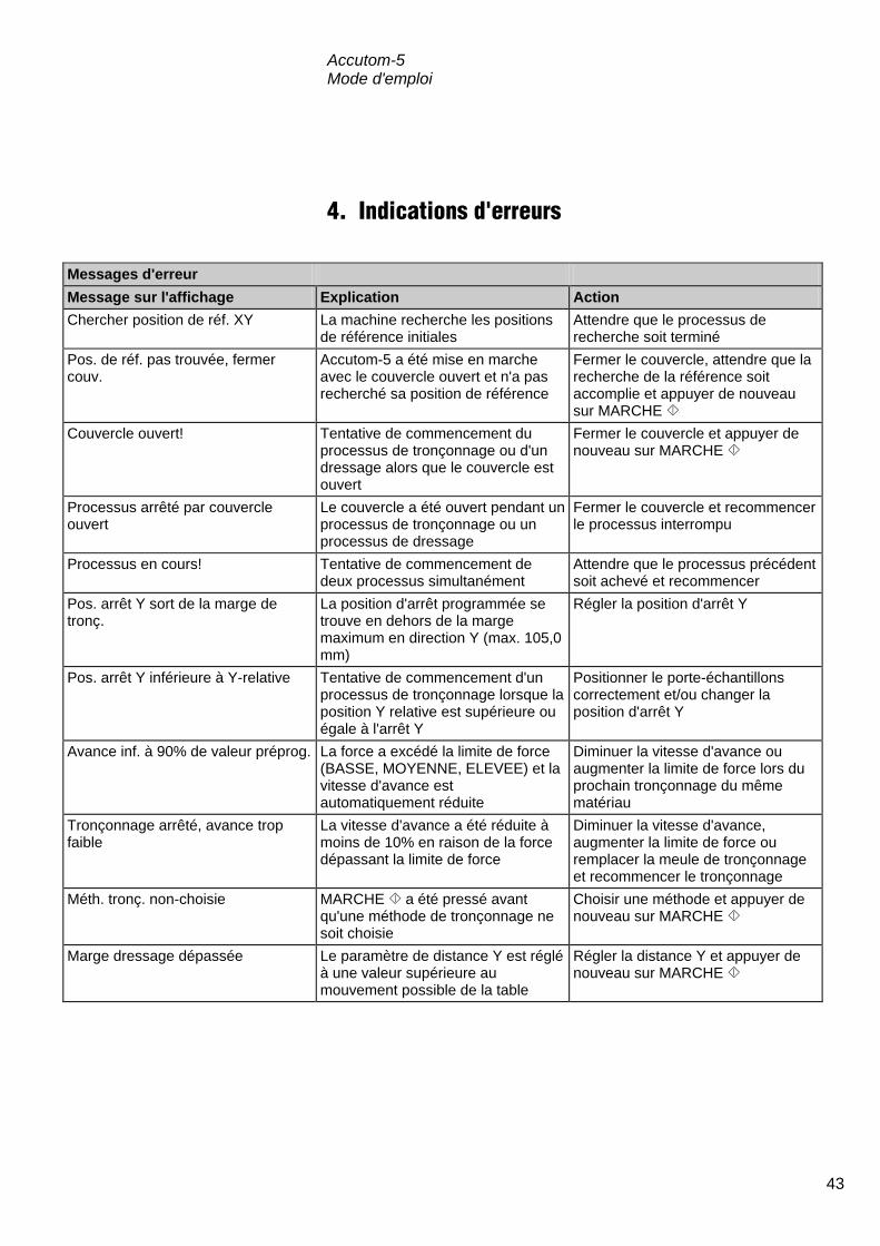
Accutom-5 Mode d'emploi
43
4. Indications d'erreurs
Messages d'erreur Message sur l'affichage Explication Action Chercher position de réf. XY La machine recherche les positions
de référence initiales Attendre que le processus de recherche soit terminé
Pos. de réf. pas trouvée, fermer couv.
Accutom-5 a été mise en marche avec le couvercle ouvert et n'a pas recherché sa position de référence
Fermer le couvercle, attendre que la recherche de la référence soit accomplie et appuyer de nouveau sur MARCHE
Couvercle ouvert!
Tentative de commencement du processus de tronçonnage ou d'un dressage alors que le couvercle est ouvert
Fermer le couvercle et appuyer de nouveau sur MARCHE
Processus arrêté par couvercle ouvert
Le couvercle a été ouvert pendant un processus de tronçonnage ou un processus de dressage
Fermer le couvercle et recommencer le processus interrompu
Processus en cours! Tentative de commencement de deux processus simultanément
Attendre que le processus précédent soit achevé et recommencer
Pos. arrêt Y sort de la marge de tronç.
La position d'arrêt programmée se trouve en dehors de la marge maximum en direction Y (max. 105,0 mm)
Régler la position d'arrêt Y
Pos. arrêt Y inférieure à Y-relative Tentative de commencement d'un processus de tronçonnage lorsque la position Y relative est supérieure ou égale à l'arrêt Y
Positionner le porte-échantillons correctement et/ou changer la position d'arrêt Y
Avance inf. à 90% de valeur préprog. La force a excédé la limite de force (BASSE, MOYENNE, ELEVEE) et la vitesse d'avance est automatiquement réduite
Diminuer la vitesse d'avance ou augmenter la limite de force lors du prochain tronçonnage du même matériau
Tronçonnage arrêté, avance trop faible
La vitesse d'avance a été réduite à moins de 10% en raison de la force dépassant la limite de force
Diminuer la vitesse d'avance, augmenter la limite de force ou remplacer la meule de tronçonnage et recommencer le tronçonnage
Méth. tronç. non-choisie MARCHE a été pressé avant qu'une méthode de tronçonnage
Choisir une méthode et appuyer de nouveau sur MARCHE ne
soit choisie Marge dressage dépassée
Le paramètre de distance Y est réglé à une valeur supérieure au mouvement possible de la table
Régler la distance Y et appuyer de nouveau sur MARCHE

Accutom-5 Mode d'emploi
44
Messages d'erreur Message sur l'affichage Explication Action Palpeur X-MIN non-activé Le palpeur inductif ne parvient pas à
détecter la position finale de la table X
Vérifier qu'il n'y a pas de blocage mécanique de la table. Si cela n'est pas le cas, appelez le SAV Struers
Palpeur X-MIN non-désactivé Le palpeur inductif de la position X ne peut pas être désactivé
Vérifier qu'il n'y a pas de blocage mécanique de la table. Si cela n'est pas le cas, appelez le SAV Struers
Erreur encoder La table Y ne se déplace pas, ou l'encoder est défectueux
Vérifier qu'il n'y a pas de blocage mécanique de la table. Si cela n'est pas le cas, appelez le SAV Struers
Moteur tronç. surchargé Le moteur principal a été exposé à une charge élevée pendant un certain temps
Attendre que le moteur soit refroidi. “Moteur tronç. prêt après surcharge” apparaîtra bientôt sur l'écran. Régler les paramètres de processus pour éviter les répétitions
Problèmes de machine Explication Action La pompe de recyclage ne fonctionne pas correctement
Le niveau d’eau dans le réservoir de recyclage est trop bas
Vérifier qu’il y a suffisamment d’eau dans le réservoir de recyclage
L’écoulement de l’eau est bloqué Retirer les tubes de refroidissement et faire fonctionner la pompe de recyclage. Rincer les tubes de refroidissement à l’eau propre avant de remplacer
La pompe de recyclage est polluée par des résidus de tronçonnage
Rincer la pompe à l’eau propre en pressant avec précaution de l’eau fraîche dans le tube d’arrivée
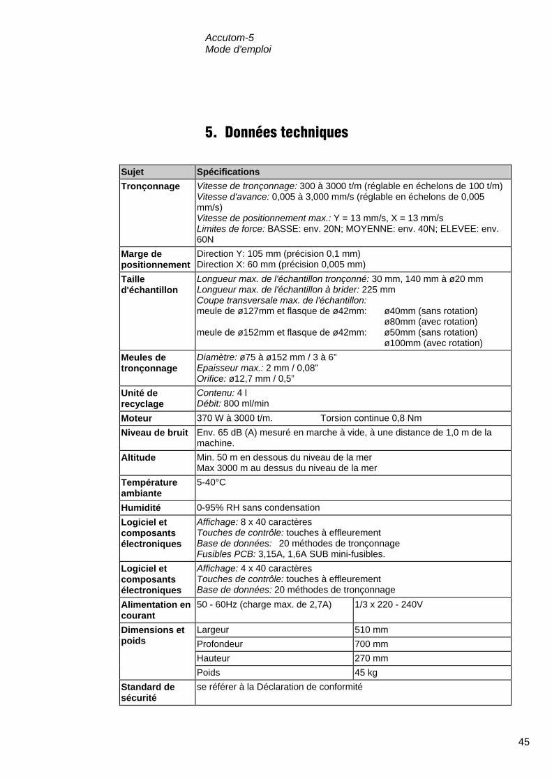
Accutom-5 Mode d'emploi
45
5. Données techniques
Sujet Spécifications Tronçonnage Vitesse de tronçonnage: 300 à 3000 t/m (réglable en échelons de 100 t/m)
Vitesse d'avance: 0,005 à 3,000 mm/s (réglable en échelons de 0,005 mm/s) Vitesse de positionnement max.: Y = 13 mm/s, X = 13 mm/s Limites de force: BASSE: env. 20N; MOYENNE: env. 40N; ELEVEE: env. 60N
Marge de positionnement
Direction Y: 105 mm (précision 0,1 mm) Direction X: 60 mm (précision 0,005 mm)
Taille d'échantillon
Longueur max. de l'échantillon tronçonné: 30 mm, 140 mm à ø20 mm Longueur max. de l'échantillon à brider: 225 mm Coupe transversale max. de l'échantillon: meule de ø127mm et flasque de ø42mm: ø40mm (sans rotation) ø80mm (avec rotation) meule de ø152mm et flasque de ø42mm: ø50mm (sans rotation) ø100mm (avec rotation)
Meules de tronçonnage
Diamètre: ø75 à ø152 mm / 3 à 6” Epaisseur max.: 2 mm / 0,08” Orifice: ø12,7 mm / 0,5”
Unité de recyclage
Contenu: 4 l Débit: 800 ml/min
Moteur 370 W à 3000 t/m. Torsion continue 0,8 Nm Niveau de bruit Env. 65 dB (A) mesuré en marche à vide, à une distance de 1,0 m de la
machine. Altitude Min. 50 m en dessous du niveau de la mer
Max 3000 m au dessus du niveau de la mer Température ambiante
5-40°C
Humidité 0-95% RH sans condensation Logiciel et composants électroniques
Affichage: 8 x 40 caractères Touches de contrôle: touches à effleurement Base de données: 20 méthodes de tronçonnage Fusibles PCB: 3,15A, 1,6A SUB mini-fusibles.
Logiciel et composants électroniques
Affichage: 4 x 40 caractères Touches de contrôle: touches à effleurement Base de données: 20 méthodes de tronçonnage
Alimentation en courant
50 - 60Hz (charge max. de 2,7A) 1/3 x 220 - 240V
Dimensions et poids
Largeur 510 mm Profondeur 700 mm Hauteur 270 mm Poids 45 kg
Standard de sécurité
se référer à la Déclaration de conformité

Accutom-5 Mode d'emploi
46
6. Structure de Menus
Accutom-5 Structure de menus
MENU PRINCIPAL
F1 Copier Choisir
méthodes tronçonnage
F2 Insérer Fonctions manuelles Configuration F3 Effacer
F4 Nom
Rotation échantillon
Meules de tronçonnage
Paramètres de tronçonnage
Editer Pompe de recyclage Paramètres Options
Dressage des meules
boisseaux Langue
X-rétracte Contraste
PROCESSUS DE TRONÇONNAGE
COMMENCE

Accutom-5 Mode d'emploi
47
Référence rapide Appuyer sur ESC jusqu'à ce que le Menu principal apparaisse. Choisir Méthodes de tronçonnage ou prépolissage et appuyer sur
ENTER e. Choisir la méthode à utiliser et appuyer sur ENTERe. Appuyer sur l'une des touches de positionnement N O pour parvenir à
l'écran de positions Y. Placer le porte-échantillons avec l'échantillon dans la tête du porte-
échantillons et le brider. Si la longueur de tronçonnage est déjà connue (c'est à dire le diamètre
de l'échantillon) : Positionner l'échantillon correctement en face de la meule de
tronçonnage à l'aide des touches de positionnement. Appuyer sur l'une des touches de positionnement N O pour parvenir à
l'écran de positions Y. Appuyer sur F1: A ZERO pour remettre à zéro la position Y relative. Appuyer sur ENTERe et utiliser les flèches de MENU qQ pour
régler la valeur d'arrêt Y. Appuyer de nouveau sur Retour e pour accepter la nouvelle valeur ou sur ESC pour annuler.
Si la longueur de l'échantillon n'est pas connue à l'avance: Positionner l'échantillon correctement en face de la meule de
tronçonnage à l'aide des touches de positionnement. Appuyer sur F1: A ZERO pour remettre à zéro la position relative X. Appuyer sur l'une des touches de positionnement N O pour parvenir à
l'écran de positions Y. Appuyer sur F1: A ZERO pour remettre à zéro la position relative Y. Déplacer l'échantillon vers la droite à l'aide des touches de
positionnement > afin qu'il puisse passer le long de la meule de tronçonnage.
Déplacer l'échantillon le long de la meule de tronçonnage à la position d'arrêt désirée à l'aide de la touche de position O. Appuyer sur F2: ARRET pour enregistrer la position d'arrêt.
Appuyer sur F3:A ZERO RELATIF pour faire revenir l'échantillon à la position initiale Y.
Appuyer sur l'une des touches de positionnement <> ou [] pour parvenir à l'écran des positions X.
Appuyer sur F3:A ZERO RELATIF pour faire revenir l'échantillon à la position initiale X.
Appuyer sur MARCHE s pour commencer le processus de
tronçonnage.
Charger une méthode de tronçonnage
Positionner l'échantillon
Commencer le processus
Les flèches suivantes sur l'affichage indiquent la direction dans laquelle le porte-échantillons est déplacé, par exemple:
POSITIONS X pP
POSITIONS Y oO

Accutom-5 使用手册
手册编号: 14947001
发行日期:15.11.2012
Accutom-5 使用手册
目录 页码
用户指南 ..................................................................... 1参考指南 ................................................................... 25快速参考指南 ............................................................ 47
如果您有技术问题需要咨询或者当您需要订购配件时,请务必说明序号以及电压/频率。您可在机身的型号牌
上找到该产品序号和电压。我们可能还会要求您提供手册的发布日期和编号。这些信息可以在封面页找到。 应注意遵守以下相关限制,若违反本限制,Struers 有权拒绝履行相关法定义务: 使用手册: Struers 使用手册仅可用于其所涉及到的 Struers 设备。 服务手册: Struers 服务手册仅可由 Struers 授权的受训技术人员使用。仅用于其所涉及到的 Struers 设备。 Struers 公司对手册文字/插图中的错误不负任何责任。手册中相关信息的改变恕不另行通知。手册中可能会提
到当前版本设备中未包括的零配件。 手册内容版权归 Struers 所有。未经 Struers 公司书面许可,请勿对手册内容进行复制。 版权所有© Struers 2012 Struers A/S Pederstrupvej 84 DK-2750 Ballerup Denmark 电话 +45 44 600 800 传真 +45 44 600 801

Accutom-5 使用手册
Accutom-5 安全防范表
使用前务必仔细阅读 1. 有关本机器及其切割轮的使用,必须根据本使用手册及切割轮使用说明
对使用者进行必要的培训和指导。
2. 机器必须安置在安全稳当的工作台上。
3. 必须确保机器运行的实际电压值在机身背部标注的电压范围内。机器必
须接地。
4. 必须使用完好无损的切割轮。切割轮最小转速为 3000 rpm。如使用其他
切割轮或锯齿形砂轮,必须确保切割轮或锯齿形砂轮的速度在符合
Accutom-5 所规定的最大转速范围内。
5. 对冷却液添加剂进行处理、混合、填充、倾倒和废弃时应遵守当地的安
全守则。
6. 必须将试样牢固固定在试样夹具座上。
7. 使用定位控制器进行试样定位时,不得接触试样、试样夹具座头部或切
割轮。
8. 切割轮未完全停止运转时,不得打开机盖。
本设备仅作特定用途,操作必须严格遵循此使用手册。
本设备设计结合使用由 Struers 提供的耗材。如因误用、安装不当、改装、疏忽、意外或维修不当而导致用户
受伤或设备受损,Struers 概不负责。
在维护或维修过程中,应由训练有素的资深技术人员(机电、电子、机械、风动等)来拆卸设备部件。

Accutom-5 使用手册
废弃处理
标有 WEEE 符号的设备含有电子或电气元件,禁止作为一般的废物
处理。 关于如何依据本国法规对这些设备进行合法处理,请咨询您当地有关 的政府部门获取更多信息。

Accutom-5 使用手册
1
用户指南 目录 页码
1. 开始
检查包装内容 ...................................................................................... 3 放置 Accutom-5 .................................................................................. 3 开始认识 Accutom-5 ........................................................................... 3 电源 .................................................................................................... 4
改变电压设置............................................................................... 4 循环冷却装置 ...................................................................................... 6 软件设置 ............................................................................................. 7
配置菜单 ...................................................................................... 7 语言设置 ...................................................................................... 8
2. 基本操作
使用控制器 ......................................................................................... 9 Accutom-5 的面板控制器 ............................................................. 9 按键群 ......................................................................................... 9 声响信号 ...................................................................................... 9 总开关位置 .................................................................................. 9
面板控制器 ....................................................................................... 10 显示 ........................................................................................... 11
读取显示 ........................................................................................... 12 更改/编辑数值 ................................................................................... 13
数值 ........................................................................................... 13 字母数字值 ................................................................................ 14
定位试样 ........................................................................................... 15 原始位置 .................................................................................... 15 绝对位置 .................................................................................... 15 相对位置 .................................................................................... 15 相对起始位置............................................................................. 15 停止位置 .................................................................................... 15
切割 .................................................................................................. 16 更换切割轮 ................................................................................ 16 夹持试样及试样夹具座 .............................................................. 17 定位试样 .................................................................................... 17

Accutom-5 使用手册
2
设置切割参数 .................................................................................... 18 切割轮 ....................................................................................... 18 速度 ........................................................................................... 18 进给 ........................................................................................... 18 切割力 ....................................................................................... 18 旋转 ........................................................................................... 19 水 .............................................................................................. 19
启动切割 ........................................................................................... 19 切割期间 ........................................................................................... 20
更改进给速度............................................................................. 20 退出试样 .................................................................................... 20 达到切割力范围 ......................................................................... 20
停止切割 ........................................................................................... 21 自动停止 .................................................................................... 21 手动停止 .................................................................................... 21
3. 维护
日常维护 ........................................................................................... 22 检查循环冷却装置 ..................................................................... 22
周维护 .............................................................................................. 23 重新填充冷却水箱 ............................................................................. 23
清空与清洗水箱 ......................................................................... 23 填充水箱 .................................................................................... 23
维护切割轮 ....................................................................................... 24 维护金刚石及 CBN 切割轮......................................................... 24 存放磨削切割轮 ......................................................................... 24

Accutom-5 使用手册
3
1. 开始 包装箱内应有以下部件: 1 Accutom-5 2 主电缆 1 带平行虎钳的试样夹具座 1 切割轮法兰(42 mm 直径) 1 止动销 1 扳手,17mm 1 小铁格栅 1 大铁格栅 1 内六角扳手,2 mm 1 内六角扳手,2.5 mm 1 内六角扳手,3 mm 1 内六角扳手,4 mm 1 内六角扳手,5 mm 2 螺钉 M4x20 2 螺钉 M4x35 1 使用手册,套 Accutom-5 应放置在稳定的平面工作台上(公差为±1 mm)。工作台
必须至少可承受 50 kg 的重量。 请您花一些时间熟悉 Accutom-5 组件的位置及其名称。
A 面板/面板控制器 B 总开关 C 循环冷却装置 D 切割轮 E 试样夹具座头部
检查包装内容
放置Accutom-5
开始认识Accutom-5

Accutom-5 使用手册
4
安装电气设备时,切记切断电源!
出厂电压设置为 240 V。
从机器背部上的电缆终端中拔下保险丝盒。 将电压开关旋转至适当的档位设置。
要求电压 设置 230 或 240 V 240 V
200 或 220 V 200 V
注意:不得使用另 2 种电压值——110 V 与 120 V。
重新插上电压开关。 将保险丝盒重新插入电缆终端。
电源
危险! 机器必须接地
重要 检查主线电压是否在机器背部型号牌上规定的电压值范围内。
改变电压设置
如出厂设置与实际主线电源供应设置不符,则可在 220 V 至 240 V 之间对此
设置加以改变:

Accutom-5 使用手册
5
Accutom-5 配备 2 种类型主线电缆: 2 插脚(欧洲 Schuko)插头适用于单相连接。 如该电缆插头不适用于您的国家,则必须选用适当的插头来代替。导
线必须按以下方式进行连接: 黄/绿:地线 褐色: 火线(带电) 蓝色: 中线 3 插脚(北美 NEMA)插头适用于 3 相电源接头。 如该电缆插头不适用于您的国家,则必须选用适当的插头来代替。导
线必须按以下方式进行连接: 绿色:地线 黑色:火线(带电) 白色:火线(带电) 另一终端上的 2 条电缆都配备有 IEC 320 电缆接头(其均需连接在
Accutom 上)。
单相供电
3相供电
连接至机器
警告! 此电缆输出电压为 200 – 240 V,而非 110 V。
不得将此电缆连接在使用 110 V 电源的机器上。此操作将可能导致财产损
失。

Accutom-5 使用手册
6
拔出循环水箱。 往水箱里注入 3.88 l 水及 120 ml Struers 冷却液添加剂。水位应
在水箱盖前排洞孔边缘以下 5 mm 处。
检查水箱盖是否安全就位在循环水箱上,并再次将带循环水箱的
抽屉式部件推回原位。 检查进水管末端是否安装到位。
循环冷却装置
重要! 应始终确保水箱内储水充足,如储水耗尽,将导致循环泵受损。
注意: 冷却水至少每月需更换 1 次。
重要 冷却水中的 Struers 添加剂必须始终维持合适的浓度(添加剂容器上规定有
百分比)。每次注水时切记添加 Struers 添加剂。仅可使用 Struers 添加剂,
不得使用任何由石油、汽油或松节油制成的添加剂。

Accutom-5 使用手册
7
总开关上的电源开关位于机器背部。将短暂显示如下图案:
然后,显示屏将改变为与 Accutom-5 关闭前的显示屏相同的屏幕,通
常为一种切割方法。第一次打开 Accutom-5 时,显示屏上应出现“主
菜单”。如显示屏上的显示有异,则应按下退出键,直至出现“主菜
单”(可听见较长的嘟嘟声)。 “主菜单”为菜单结构的最高级别。在这里,可进入“配置”、“手
动功能”及“切割方法”等菜单。
MAIN MENU
CUTTING METHODS MANUAL FUNCTIONS
CONFIGURATION
按下菜单上/下键选择“配置”。
按下回车键激活“配置”菜单。
CONFIGURATION
CUT-OFF WHEELS
OPTIONS
软件设置 配置菜单
主菜单 切割方法 手动功能 配置
配置 切割轮 选项

Accutom-5 使用手册
8
按下菜单上/下键选择“选项”。
CONFIGURATION
CUT-OFF WHEELS
OPTIONS
按下回车键激活“选项”菜单。
OPTIONS
Language : ENGLISH X-retract : OFF
Contrast : 40
F1: DEFAULT VALUE
按下回车键激活“语言”菜单。
LANGUAGE
ENGLISH DEUTSCH FRANÇAIS
ESPAÑOL
按下菜单上/下键选择需要的语言。
按下回车键确定此语言。 “选项”菜单将以您选择的语言显示。
语言设置
配置 切割轮 选项
选项 语言:英语 X-缩进:关 对比: 40 F1:默认值
语言 英语 德语 法语 西班牙语

Accutom-5 使用手册
9
2. 基本操作
A 编程与监控功能 B 定位试样夹具座 C 启动/停止 Accutom-5 短嘟音:按下按键后,出现短嘟音,表明命令已接受。 长嘟音:此时表明该按键尚未激活。 总开关位于机器背部。
使用控制器 Accutom-5 的面板控制器
按键群
声响信号
总开关位置
请注意 即使关闭总开关,程序内存中的数据也不会丢失。

Accutom-5 使用手册
10
名称 按键 功能 名称 按键 功能
总开关
总开关位于机器背部。
退出
Esc 退出当前菜单或试样夹具座位置
界面。
启动
根据预设的方法,启动切割程
序。如选择了循环水,则会打开
此功能。
快速定位
(左)
切换至“定位”菜单或将试样夹
具座在 X 方向以 100 µm 步长左
移。持续按住按键以加快速度。
停止
停止切割程序。如选择了循环
水,则会关闭此功能。
快速定位
(右)
切换至“定位”菜单或将试样夹
具座在 X 方向以 100 µm 步长右
移。持续按住按键以加快速度。
功能键
F1/F2 F3/F4
多种用途控制。参见各单独屏幕
底部说明。
位置左
切换至“定位”菜单或将试样夹
具座在X方向以 5 µm步长慢慢左
移。持续按住按键以加快速度。
菜单
Accutom-5 树形结构菜单内上翻
() /下翻()键。设置参数时,数
值将增加()或减少(
)。
位置右
切换至“定位”菜单或将试样夹
具座在 X 方向以 5 µm 步长慢慢
右移。持续按住按键以加快速
度。
回车
选择标出的参数值或选择 1 个菜
单。
位置上/下 /
更改定位菜单或将试样夹具座在
Y 方向以 100 µm 步长上移或下
移。持续按住按键以加快速度。
面板控制器

Accutom-5 使用手册
11
SELECT CUTTING METHOD
1.EMPTY METHOD 2.EMPTY METHOD 3.EMPTY METHOD 4.EMPTY METHOD 5.EMPTY METHOD 6.EMPTY METHOD 7.EMPTY METHOD 8.EMPTY METHOD 9.EMPTY METHOD 10.EMPTY METHOD 11.EMPTY METHOD 12.EMPTY METHOD
F1:COPY F2:INSERT F3:RESET F4:RENAME A 标题 B 反向文本、光标 C 功能键选项 D 箭头表示下方还有更多内容供显示
显示
请注意 此使用手册中的显示屏示例列出了多种可能出现的文本。实际显示屏可能与
使用手册中的示例有出入。
选择切割方法 空方法 F1:复制 F2:插入 F3:重置 F4:重命名
B
C
A D

Accutom-5 使用手册
12
显示屏可显示各种类型的信息,如切割方法及取样位置等。以下示例
为切割方法显示屏:
Cutting Method: 1. EMPTY METHOD
Wheel :B0D15 Speed : 2700 rpm Feed :0.100 mm/s Force : MEDIUM Rotation: OFF
Water : ON
按下其中一个 X 轴定位按键,则屏幕会转变如下:
X-POSITIONS
Absolute Position: 15.255 mm
Relative Position: 5.000 mm
F1:RESET F2:ADD F3:MOVE TO REL. ZERO
按下其中一个 Y 轴定位按键,则屏幕会转变如下:
Y-POSITIONS
Absolute Position: 55.7 mm
Relative Position: 0.0 mm
Stop Position: 20.0 mm
F1:RESET F2:SET STOP F3:MOVE TO REL.ZERO
Esc 按下退出键,将返回切割方法界面。
读取显示
显示屏上的“粗”箭头显
示试样夹具座的活动方
向,例:
X 位置
Y 位置
切割方法:1、空方法 切割轮: 速度: 进给: 切割力:中 旋转:关 水:开
X 位置 绝对位置: 相对位置: F1:重置 F2:增加 F3:移动至相对起始位置
Y 位置 绝对位置: 相对位置: 停止位置: F1:重置 F2:设置停止 F3:移动至相对起始位置

Accutom-5 使用手册
13
根据数值类型,有两种不同的编辑方法。
Cutting Method: 1. EMPTY METHOD
Wheel : B0D15 Speed : 2700 rpm Feed :0.100 mm/s Force : MEDIUM Rotation: OFF
Water : ON
按下菜单上/下键选择需要更改的数值,如进给:
Cutting Method: 1. EMPTY METHOD
Wheel : B0D15 Speed : 2700 rpm Feed :0.100 mm/s Force : MEDIUM Rotation: OFF
Water : ON
按下回车键,编辑数值。
数值周围出现 2 个方括号[ ]。
Cutting Method: 1. EMPTY METHOD
Wheel : B0D15 Speed : 2700 rpm Feed [0.100]mm/s Force : MEDIUM Rotation: OFF
Water : ON
按下菜单上/下键,增加或减少数值。
按下回车键,确定新数值。
或
Esc 按下退出键,保持原数值。
更改/编辑数值
数值
切割方法:1、空方法 切割轮: 速度: 进给: 切割力:中 旋转:关 水:开
切割方法:1、空方法 切割轮: 速度: 进给: 切割力:中 旋转:关 水:开
切割方法:1、空方法 切割轮: 速度: 进给: 切割力:中 旋转:关 水:开

Accutom-5 使用手册
14
Cutting Method: 1. EMPTY METHOD
Wheel : B0D15 Speed : 2700 rpm Feed :0.100 mm/s Force : MEDIUM Rotation: OFF
Water : ON
按下菜单上/下键,选择需要更改的文字值,如切割轮:
按下回车键,编辑此文字值。
出现一个子菜单。
CUT-FF WHEELS
M0D08 M1D08 M0D10 M1D10 M0D13 M1D13 B0D13 B0C13 50A13 30A13 SAW13 M0D15 M1D15 E0D15 B0D15 B0C15 50A15 40A15 10S15 30A15 USER 1 USER 2 USER 3 USER 4 USER 5
USER 6 USER 7 USER 8 USER 9 USER10
按下菜单上/下键选择合适的切割轮。
按下回车键确定新数值,并返回上一级界面。
或
Esc 按下退出键,保持原数值并返回上一级界面。
字母数字值
切割方法:1、空方法 切割轮: 速度: 进给: 切割力:中 旋转:关 水:开
切割轮
用户 1 用户 2 用户 3 用户 4 用户 5 用户 6 用户 7 用户 8 用户 9 用户 10
Accutom-5 使用手册
15
在将试样夹入试样夹具座后,试样夹具座将固定在试样夹具座头部。
使用定位键来移动试样夹具座及试样。显示屏将显示 X 或 Y 方
向位置。 每次机盖关闭状态下打开电源后,Accutom-5 都将检测其原始位置。
试样夹具座头部将尽最大可能返回至原始位置(X=0.000,Y=0.0)。其
后返回至电源打开前的位置。 绝对位置将显示试样夹具座离原始位置的总距离。 当将其在目的点上设置为零时,相对位置与绝对位置相同。通过归零
设置,试样(接近切割轮)运动计算将更容易。屏幕值将一直显示为
归零后试样夹具座的运动距离。 相对起始位置即 X 或 Y 位置内的相对位置归零后的那个点。切割程序
完成后,试样夹具座将自动返回至该点。显示 X 或 Y 位置屏幕时,按
下 F3 键,试样夹具座同样将返回相对起始位置。 设置停止位置可在精确点上停止切割程序。到达该点后,试样将取消
运行,并返回相对起始位置。 设置停止位置以更换可能磨损的切割轮。使用Al2O3
或SiC切割轮时,
这一点至关重要。
定位试样
原始位置
绝对位置
相对位置
相对起始位置
停止位置
更换磨损轮

Accutom-5 使用手册
16
打开机盖,在空中旋转右冷却管。 将止动销插入到内法兰的孔中。 使用扳手(17mm)将法兰螺丝拧松。 拆下外部法兰和砂轮。
安装新切割轮,重新安装外法兰,加工面面朝内法兰。 将定位销嵌入内法兰洞孔中。 轻轻地用扳手将法兰螺钉拧紧。 旋转右冷却管至其初始位置。
切割 更换切割轮
重要 主轴与内法兰间的空间极其微小,因此必须保证两者表面完全清洁光滑。不
得强行把切割轮装上去,这样会损坏主轴。如果上面有细小的毛刺,可用砂
纸(1200#)磨去。
套筒扳手
止动销
带插头的冷却
管

Accutom-5 使用手册
17
使用适当的内六角扳手将试样牢牢地固定在试样夹具座上。 将试样夹具座推入咬合器,以便将试样夹具座固定在试样夹具座
头部。使用内六角扳手拧紧螺钉。 旋转切割或振动切割时,应将试样及试样夹具座夹紧,以便它们
能均匀地围绕试样中心旋转。因切割轮在大部分时间内都在进行
切割,从而可达到最快速的切割效果,而切割轮磨损的可能性也
大大降低。 使用定位键,将试样移至接近切割轮的正确的启动点。 在各自界面下,按下 F1 键,重置 X 及 Y 方向的相对位置。 设置停止位置,以确定切割长度: 设置停止位置方法有二: 1. 如知道试样规格:
− 按下回车键并使用菜单上/下键,设置停止值。 − 再次按下回车键以确定新数值,或按下退出键取消。
2. 不知道试样精确规格时:
− 使用定位键定位试样;这样即可将试样沿着切割轮方向移
动。 − 使用定位键将试样沿着切割轮方向移动,直至需要停止的位
置。 − 按下 F2 键(设置停止值),以记录停止位置。 − 按下 F3 键(移至相对起始位置),将试样移回初始位置。 − 使用定位键将试样定位在切割轮前部合适的位置。如有必
要,可使用 F3 键(移至相对起始位置)。
夹持试样及试样夹具座
定位试样
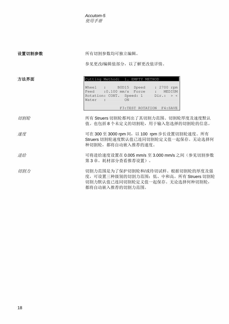
Accutom-5 使用手册
18
所有切割参数均可独立编辑。 参见更改/编辑值部分,以了解更改值详情。
Cutting Method: 1. EMPTY METHOD
Wheel : B0D15 Speed : 2700 rpm Feed :0.100 mm/s Force : MEDIUM Rotation: CONT. Speed: 1 Dir.: > <
Water : ON
F3:TEST ROTATION F4:SAVE
所有 Struers 切割轮都列出了其切割力范围、切割轮厚度及速度默认
值。也包括 8 个未定义的切割轮,用于输入您选择的切割轮的信息。 可在 300 至 3000 rpm 间,以 100 rpm 步长设置切割轮速度。所有
Struers 切割轮速度默认值已连同切割轮定义值一起保存。无论选择何
种切割轮,都将自动嵌入推荐的速度。 可将进给速度设置在 0.005 mm/s 至 3.000 mm/s 之间(参见切割参数
第 3 章。耗材部分查看推荐设置)。 切割力范围是为了保护切割轮和/或待切试样。根据切割轮的厚度及强
度,可设置三种级别的切割力范围:低、中和高。所有 Struers 切割轮
切割力默认值已连同切割轮定义值一起保存。无论选择何种切割轮,
都将自动嵌入推荐的切割力范围。
设置切割参数
方法界面
切割轮
速度
进给
切割力

Accutom-5 使用手册
19
切割大型、坚硬、有涂层或较长的试样时,试样旋转功能极具优势。 试样不旋转。 试样围绕其中心位置旋转。 可设置三种不同级别的速度:1、2 或 3。 旋转方向可设为同向或逆向。 推荐逆向。 按下 F3 键,使用参数测试试样旋转。 试样围绕其中心位置摇摆/振动。 可设置三种不同级别的速度:1、2 或 3。 可在 10°至 400°间调节角度。 按下 F3 键,使用参数测试试样旋转。
冷却水可设置为开或关。对于常用的切割操作来说,一般设置成开
启。 启动切割前,应确保切割室干净,以保证冷却水自由流动。 正确定位试样。 设置合适的切割参数。 确保已安装合适的切割轮。 关闭机盖。 按下启动键。
旋转 仅带有旋转装置的 Accutom-5 才具
备旋转功能
旋转:关闭
旋转:持续
旋转:振动
注意 当试样在 X 或 Y 方向移动,旋转设置为逆向或振动时,屏幕将短暂出现警告
信息“旋转模式”,提示已选中旋转模式。
水
启动切割
逆向 同向

Accutom-5 使用手册
20
按下启动键后,显示屏将转换如下:
Feed Speed CUTTING STARTED
0% 100%
Pre-set Feed Speed : 0.100 mm/s Actual Feed Speed : 0.100 mm/s
Remaining Process Time: 3 min
同时显示预设及实际进给速度。横条用于图解显示进给速度。 切割进程中可更改进给速度。按下回车键,设置合适的值以更改进给
速度。再次按下回车键确定此次更改,或按下退出键取消。 切割进程启动后,只有从切割轮上回撤试样时才有可能移动试样。可
通过按下“向下定位”键来完成此操作。试样将停止前进,并向后移
动直至再次松开按键。然后,试样将再次以预设的进给速度前进。如
因切割力范围限制而无法达到预设的进给速度,Accutom- 5 将自动降
低进给速度至最大可能的速度。将显示此值,并在切割完成后显示如
下信息:
CUTTING FINISHED
Force limit was reached during cutting feed speed reduced to:
0.070 mm/sec
如果后面还要切割相似试样,进给速度应减至新值或更低数值。
切割期间
更改进给速度
退出试样
达到切割力范围
进料速度 切割启动 预设进给速度: 实际进给速度: 剩余程序时间:
切割完成 在切割时已达到切割力范
围 进给速度减至 0.070 mm/sec

Accutom-5 使用手册
21
Accutom-5 在预设的停止位置上自动停止切割进程(设置停止位
置时,应确保已补偿了可能的切割轮磨损)。 试样回撤,切割轮停止运转。 切割期间通过按下停止键
按下定位键进行 Y方向调节,再按下 F2 键(设置停止),可避
免出现切割轮仍在试样内而进程停止的现象。到达相对起始位置
时,试样将立刻回撤,进程停止。
,可随时停止切割进程。试样保持在
其实际位置上,切割程序亦在该处停止。
显示屏将返回至切割启动前的界面。
停止切割 自动停止
手动停止

Accutom-5 使用手册
22
3. 维护 用湿布清洗切割室。不得使用自来水,因其可能导致循环冷却水
箱溢流。切记将壁上的污垢颗粒全部清理掉。 清洗试样夹具座头部及楔形进给器的夹子。 清洗法兰。 用湿布清洗透明机盖。
每使用 8 小时后应对冷却装置的冷却水进行检查,或至少每周检查一
次。如冲洗泵无法到达冷却水,则必须对冷却器进行重新注水。 记得为冷却液添加 Struers 添加剂,比例为:1 份添加剂兑 33 份冷却
液。 使用折射计来检查添加剂浓度。 浓度=Brix 值。浓度应始终处于 2.7 至 3.3 %之间。如浓度过低,请为
冷却液添加 Struers 添加剂。
日常维护
警告! 不得使用酒精、丙酮或类似的溶剂。
检查循环冷却装置
重要 冷却水中的 Struers 添加剂必须始终维持合适的浓度(添加剂容器上规定有
百分比)。每次注水时切记添加 Struers 添加剂。

Accutom-5 使用手册
23
清洗试样夹具座:活动部件、楔形进给器及螺钉等。使用无酸油
进行润滑。 彻底清洗切割箱及机盖。切记将壁上的污垢颗粒全部清理掉。 循环冷却装置内的冷却水必须至少每月更换 1 次。 小心地拉出抽屉式部件,降低连接的面板。 小心地拔出平底水箱。 拆除盖板,将水箱内物质倒空在可用于倾倒化学废品的排水沟
中。 用自来水清洗水箱、分隔部分及机盖。 将分隔部分准确地安装在水箱内,并盖上机盖。 将盖板按压回水箱,并确保其已就座到位。
往水箱注入 3.88 l 清水及 120 ml Struers 添加剂。水位应在水箱
盖前排洞孔以下 5 mm 处。 将抽屉式部件连同循环水箱一起推回原处。
周维护
重新填充冷却水箱
清空与清洗水箱
重要 必须准确地安置容器及盖板,否则水泵将无法抽取冷却水。
重要 如长期不使用 Accutom,则必须用清水冲洗循环冷却系统。这将防范切割材
料的残留物干结从而导致水泵内部受损。
填充水箱
重要 应始终确保水箱内储水充足,储水耗尽将毁坏循环泵。
重要 冷却水中的 Struers 添加剂必须始终维持合适的浓度(添加剂容器上规定有
百分比)。每次注水时切记添加 Struers 添加剂。

Accutom-5 使用手册
24
金刚石及 CBN 切割轮的精密度极高,因此切割时必须谨遵以下说明: 切割轮不得超负荷工作,如重型机械负荷或热负荷。 切割轮应存放在干燥场所,水平地置放在平坦的支架上,最好有
轻微压力。 干净干燥的切割轮不会腐蚀。因此,存储前应对切割轮进行清
洁、干燥处理。如有必要,可使用普通的清洁剂进行清洗。 定期对切割轮进行修整处理亦是日常维护的一部分(参见“高级
操作”章节)。 此类型切割轮对潮湿气候极其敏感。因此,不要将新的、干燥的切割
轮与已用过的潮湿切割轮一起存放。将切割轮存放在干燥场所,水平
地置放在平坦的支架上。
维护切割轮 维护金刚石及CBN切割轮
存放磨削切割轮

Accutom-5 使用手册
25
参考指南 目录 页码
1. 高级操作
配置菜单 ........................................................................................... 26 切割轮 ....................................................................................... 27 选项 ........................................................................................... 28
手动功能 ........................................................................................... 29 试样旋转 .................................................................................... 30 循环泵 ....................................................................................... 31 修整 ........................................................................................... 32
方法选项 ........................................................................................... 34 保存方法 .................................................................................... 34 复制方法 .................................................................................... 35 插入方法 .................................................................................... 36 重置方法 .................................................................................... 37 编辑名称 .................................................................................... 38 名称编辑原则............................................................................. 39
2. 附件 ......................................................................................... 40
3. 耗材
切割轮 .............................................................................................. 41 优化切割效果 .................................................................................... 41
切割参数 .................................................................................... 41 一般切割问题............................................................................. 42
耗材 .................................................................................................. 42
4. 故障排除 ................................................................................ 43
5. 技术数据 ................................................................................ 45
6. 菜单总览 ................................................................................ 46
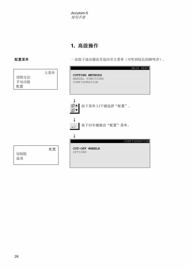
Accutom-5 使用手册
26
1. 高级操作 一直按下退出键直至返回至主菜单(可听到较长的蜂鸣音)。
MAIN MENU
CUTTING METHODS MANUAL FUNCTIONS
CONFIGURATION
按下菜单上/下键选择“配置”。
按下回车键激活“配置”菜单。
CONFIGURATION
CUT-OFF WHEELS
OPTIONS
配置菜单
主菜单 切割方法 手动功能 配置
配置 切割轮 选项
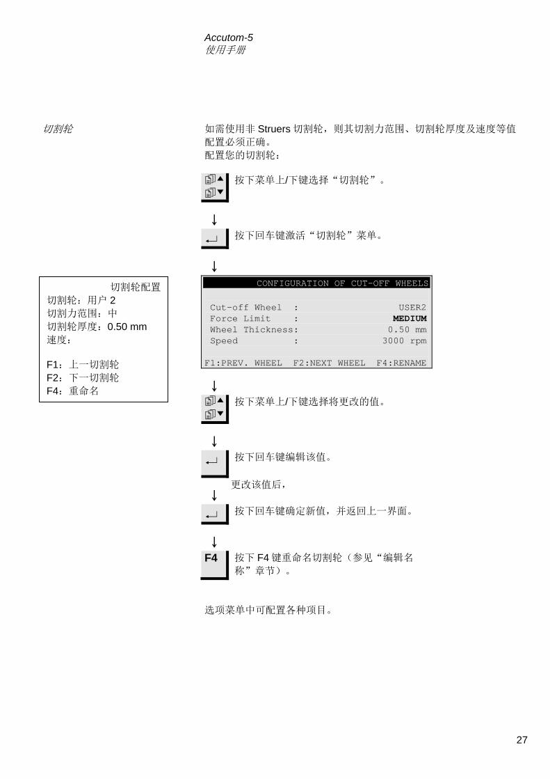
Accutom-5 使用手册
27
如需使用非 Struers 切割轮,则其切割力范围、切割轮厚度及速度等值
配置必须正确。 配置您的切割轮:
按下菜单上/下键选择“切割轮”。
按下回车键激活“切割轮”菜单。
CONFIGURATION OF CUT-OFF WHEELS
Cut-off Wheel : USER2 Force Limit : MEDIUM Wheel Thickness: 0.50 mm
Speed : 3000 rpm
F1:PREV. WHEEL F2:NEXT WHEEL F4:RENAME
按下菜单上/下键选择将更改的值。
按下回车键编辑该值。
更改该值后,
按下回车键确定新值,并返回上一界面。
F4 按下 F4 键重命名切割轮(参见“编辑名
称”章节)。
选项菜单中可配置各种项目。
切割轮
切割轮配置 切割轮:用户 2 切割力范围:中 切割轮厚度:0.50 mm 速度: F1:上一切割轮 F2:下一切割轮 F4:重命名

Accutom-5 使用手册
28
参阅本使用手册之入门章节了解如何更改语言设置。 到达停止位置后,正常情况下,试样会直接后退至相对初始位置。为
避免此活动期间接触到切割轮,可通过设置 “X 缩进” 为“开”状
态,以在重新定位前从切割轮上回撤试样。 到达相对初始位置后,试样即返回原始位置。
可调节显示屏对比设置。 按下 F1 键将重置反向选项至出厂调节的默认值。
选项 语言
X缩进
重要
确保 Y 停止位置设置正确。如在仍未切穿试样的情况下让试样退出切割轮,
则切割轮可能受损。
对比
F1:默认值

Accutom-5 使用手册
29
Accutom-5 某些功能同样可用手动来完成。可在“手动功能”菜单中
找出所有此类功能。 按下退出键直至返回主菜单。
MAIN MENU
CUTTING METHODS MANUAL FUNCTIONS
CONFIGURATION
按下菜单上/下键,选择“手动功能”。
按下回车键激活“手动功能”菜单。
MANUAL FUNCTIONS MENU
SAMPLE ROTATION RECIRCULATION PUMP
DRESSING OF CUT-OFF WHEEL
手动功能
主菜单 切割方法 手动功能 配置
手动功能菜单 试样旋转 循环泵 整形切割轮
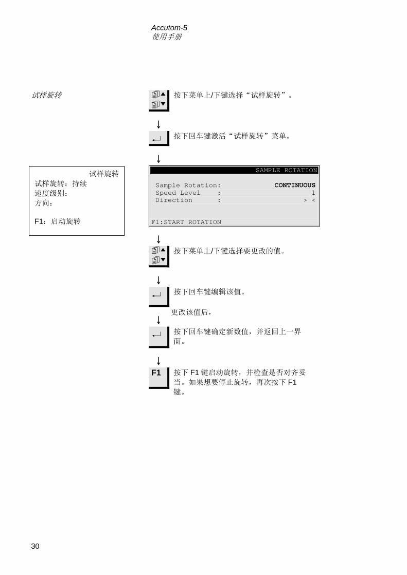
Accutom-5 使用手册
30
按下菜单上/下键选择“试样旋转”。
按下回车键激活“试样旋转”菜单。
SAMPLE ROTATION
Sample Rotation: CONTINUOUS Speed Level : 1
Direction : > <
F1:START ROTATION
按下菜单上/下键选择要更改的值。
按下回车键编辑该值。
更改该值后,
按下回车键确定新数值,并返回上一界
面。
F1 按下 F1 键启动旋转,并检查是否对齐妥
当。如果想要停止旋转,再次按下 F1键。
试样旋转
试样旋转 试样旋转:持续 速度级别: 方向: F1:启动旋转

Accutom-5 使用手册
31
从“手动功能”菜单中按下菜单上/下键选择“循环泵”。
MANUAL FUNCTIONS MENU
SAMPLE ROTATION RECIRCULATION PUMP
DRESSING OF CUT-OFF WHEEL
按下回车键激活“循环泵”选项。
RECIRCULATION PUMP
F1:START PUMP
F1 按下 F1 键,启动循环泵。 再次按下 F1 键,可以停止循环泵。
循环泵
手动功能菜单 试样旋转 循环泵 整形切割轮
循环泵 F1:启动泵

Accutom-5 使用手册
32
切割韧性材料后,金刚石及 CBN 切割轮可能需要进行修整,以获得最
佳切割效果。具体步骤如下: 安装好要修整的切割轮。 将磨刀棒夹紧在试样夹具座内,并正确定位。
− 磨刀棒必须处于切割轮前部位置,这样切割轮才能将磨刀棒
切成薄片。
从“手动功能”菜单中按下菜单上/下键,选择“修整切割
轮”。
MANUAL FUNCTIONS MENU
SAMPLE ROTATION RECIRCULATION PUMP
DRESSING OF CUT-OFF WHEEL
按下回车键激活修整选项。
修整
修整切割轮
手动功能菜单 试样旋转 循环泵 整形切割轮

Accutom-5 使用手册
33
DRESSING OF CUT-OFF WHEEL
Feed Speed : 0.5 mm/s Wheel Speed : 3000 rpm Cooling Water: ON Y-Distance
: 10.0 mm
F1:START DRESSING
按下菜单上/下键选择要更改的值。
按下回车键编辑该值。
按下回车键确定新值,并返回上一界面。
F1 按下 F1 键启动修整操作。
整形切割轮 进给速度: 轮速: 冷却水:开 Y 距离: F1:开始整形

Accutom-5 使用手册
34
当在使用一种特定的方法时,可以将您对该方法做的更改保存在数据
库中。 一旦更改了切割方法中的某一参数,显示屏底端将显示“F4:保
存”。
Cutting Method: 1. EMPTY METHOD
Wheel : B0D15 Speed : 2700 rpm Feed :0.200 mm/s Force : MEDIUM Rotation: OFF
Water : ON
F4:SAVE
F4 在更改了所有必要的参数后,按下 F4 键(保存)保存更
改。
SAVE METHOD
Save changes in method
1. EMPTY METHOD ?
ENTER: YES ESC: NO
按下回车键保存更改后的方法。
除非您已经为此方法命名,否则此方法的名字将自动从“空
方法”转为“未命名方法”。这表示这和默认方法相比,其
参数至少改变了一个。
方法选项 保存方法
重要 保存更改时,原始方法将被覆盖。如欲保留原始方法,则须对此方法进行复
制并重命名。即更改复制的方法,而不是更改原始方法。参见“复制方法”
章节。
切割方法:1、空载方法 切割轮: 轮速: 进给: 切割力: 旋转:关 水:开
F4:保存
保存方法 保存更改方法至 1.空方法? 回车键:是 退出键:否

Accutom-5 使用手册
35
复制方法是在现有方法的基础上创建新切割方法的一种捷径。 选择需要复制的切割方法。
SELECT CUTTING METHOD 1.UNNAMED METHOD 2.EMPTY METHOD 3.EMPTY METHOD 4.EMPTY METHOD 5.EMPTY METHOD 6.EMPTY METHOD 7.EMPTY METHOD 8.EMPTY METHOD 9.EMPTY METHOD 10.EMPTY METHOD 11.EMPTY METHOD 12.EMPTY METHOD
F1:COPY F3:RESET F4:RENAME
按下回车键可查看方法参数。
Esc 按下退出键返回上一界面。
F1 按下 F1 键(复制),将方法复制到缓存
中。
COPY METHOD
Do you want to copy method
1. UNNAMED METHOD to buffer?
ENTER: YES ESC: NO
按下回车键确定将方法复制到缓存中。
复制方法
选择切割方法 未命名方法 空方法 F1:复制 F3:重置 F4:重命名
复制方法 是否要将方法 1.未命名方
法复制到 缓存中? 回车键:是 退出键:否

Accutom-5 使用手册
36
如欲将一个方法插入另一个不同的方法:
按下菜单上/下键选择待插入方法的另一方
法。
如该方法非空方法:
按下回车键查看该方法。
Esc 按下退出键返回上一界面。
F2 按下 F2 键(插入),插入存放于缓存中
的方法。
INSERT METHOD
Do you want to copy from buffer to
method 4. EMPTY METHOD ?
ENTER: YES ESC: NO
按下回车键确定插入该方法。
插入方法
插入方法 是否要将缓存中的方法插
入 4.空方法中? 回车键:是 退出键:否

Accutom-5 使用手册
37
如不再使用某一方法,则应重置它。 参数将变成默认值,您可以在以后通过修改默认值轻松地将方法转换
为新方法。 方法名称将变成“空方法”,意味着您可对该方法进行复制或更改,
而不会替换掉任何有用的数据。 选择需要重置的方法。
SELECT CUTTING METHOD 1.UNNAMED METHOD 2.EMPTY METHOD 3.EMPTY METHOD 4.UNNAMED METHOD 5.EMPTY METHOD 6.EMPTY METHOD 7.EMPTY METHOD 8.EMPTY METHOD 9.EMPTY METHOD 10.EMPTY METHOD 11.EMPTY METHOD 12.EMPTY METHOD
F1:COPY F2:INSERT F3:RESET F4:RENAME
按下回车键查看该方法,并确保未删除任
何有用的数据。
Esc 按下退出键返回上一界面。
F3 按下 F3 键(重置)。
RESET METHOD
Do you want to reset this method ?
4. UNNAMED METHOD
ENTER: YES ESC: NO
按下回车键重置方法。
重置方法
选择切割方法 未命名方法 空方法 F1:复制 F2:插入 F3:重置 F4:重命名
重置方法 是否重置此方法? 4.未命名方法 回车键:是 退出键:否

Accutom-5 使用手册
38
可根据个人喜好,编辑并更改方法名称和切割轮名称。 选择需要重命名的方法或切割轮。
SELECT CUTTING METHOD 1.UNNAMED METHOD 2.EMPTY METHOD 3.EMPTY METHOD 4.UNNAMED METHOD 5.EMPTY METHOD 6.EMPTY METHOD 7.EMPTY METHOD 8.EMPTY METHOD 9.EMPTY METHOD 10.EMPTY METHOD 11.EMPTY METHOD 12.EMPTY METHOD
F1:COPY F2:INSERT F3:RESET F4:RENAME
F4 按下 F4 键(重命名)。
UNNAMED METHOD EDIT NAME
Text: UNNAMED METHOD
Press ENTER to accept the text, or press “
“ to select new character.
F1:LEFT F2:INSERT F3:DELETE F4:RIGHT
按下菜单下键进入字符集。
UNNAMED METHOD EDIT NAME
Text: UNNAMED METHOD
ABCDEFGHIJKLMNOPQRSTUVWXYZ
0123456789,.;:-!"#%&/()=?+µ
F1:LEFT F2:SPACE F3:BACKSPACE F4:RIGHT
编辑名称
选择切割方法 未命名方法 空载方法 F1:复制 F2:插入 F3:重置 F4:重命名
未命名方法 编辑名称 文本:未命名方法 按回车键确定该文本,或
按“↓”键选择新字符。 F1:左侧 F2:插入 F3:删除 F4:右侧
未命名方法 编辑名称 文本:未命名方法 F1:左侧 F2:空格
F3:退格 F4:右侧

Accutom-5 使用手册
39
使用 F1 键(左侧)或 F4 键(右侧),将主光标移至想要更改的
字符处。然后按下菜单下键进入下一行的字符集。则文本行中将
出现一个辅助光标,用来标示该字符将出现在方法名称中的位
置。 使用以下按键输入新名称: F1 将主光标左移 F2 在文本中插入一个空格 F3 删除文本左侧的一个字符 F4 将主光标右移
按下回车键在名称中插入一个新字符,并将名称中的辅助光
标右移一位。对每个字符重复以上的过程。。
使用以上名称编辑程序来输入新名称。
Esc 按下退出键,离开编辑界面。
NAME CHANGED
The name is changed, do you want to keep
the old name, or accept the new name ?
ENTER:ACCEPT NEW NAME ESC:KEEP OLD NAME
按下回车键确定新名称。
名称编辑原则
名称改变 该名称已改变,是否保留
原名称,或者接受新名
称? 回车键:接受新名称 退出键:保留原名称

Accutom-5 使用手册
40
2. 附件 规格 编号: 用于 65 mm 直径切割轮,用于 Accutom-5,以获
得最精密切割效果。 04946902
规格 编号: 通用。虎钳,最大开口为 60 mm。 04946903
用于圆型或方形试样。泪珠形夹具,最大开口为
40 mm/ ø 1 ½”。
04946904
用于异形试样,带 7 个螺钉。最大宽度为
40 mm/1 ½”
04946905
带测角仪 04276911
用于粘贴试样 04276912
用于夹紧薄片的陶瓷真空夹盘 04276913
用于小型试样。虎钳 04276915
双平行虎钳 04946909
安装在咬合器和试样夹具座之间的连接头。
可倾斜连接头,最大张角为± 10°
04946906
角形连接头,最大张角为+30/-90°。 04946908
带咬合器的底座。用于安装其他类型的试样夹具座 04276914
法兰组
试样夹具座

Accutom-5 使用手册
41
3. 耗材 请参考Struers切割轮 手册中的选择指南。 Accutom-5 可以使用的切割轮直径范围为:75 mm(法兰最小直径为
42 mm)~152 mm。孔径为 12.7 mm。
根据试样材质,结合下表,选择适当的切割轮及切割参数。 推荐的切割参数 材料 硬度 切割力范围 进给速度
[mm/s] 轮速 [rpm]*)
陶瓷、矿物及晶体
> HV 800
低 0.005-0.15 3000
低 0.005-0.20 3000
高 0.005-0.30 3000
高 0.005-0.30 2700
硬质合金与硬陶 > HV 800
中 0.005-0.25 3000
中 0.005-0.25 2700
极硬的黑色金属 > HV 500 中 0.005-0.25 3000
硬及较硬的黑色金属 HV 350-800
中 0.05-0.30 1000-3000
中 0.05-0.30 1000-3000
较大尺寸的硬及较硬的
黑色金属 HV 350-800
中 0.05-0.30 1000-3000
软及中等软度金属 HV 30-350
中 0.05-0.30 1000-3000
中 0.05-0.30 1000-3000
柔韧的有色金属 HV 70-400 中 0.05-0.30 1000-3000
塑料及较软的金属 < HV 100 中 0.05-0.30 最大 1200
*) 为获得更低磨损及更好的表面制备效果,请总是采用推荐的最高的切割轮速度。
切割轮
重要! 始终使用大法兰(65 mm),以获得最高可能的精密度。
优化切割效果
切割参数

Accutom-5 使用手册
42
下表即为常见切割问题的可能解答: 优化切割效果 目标 实现方法 更好的表面品质 采用推荐的最低进给速度,且不旋转试样夹具座。
更低的切割轮磨损 采用推荐的最低进给速度,且不旋转试样夹具座。使用树脂
键切割轮及所有磨削切割轮时,则尤为重要。
磨削切割轮相关问
题? 使用磨削切割轮时,不得采用超出推荐范围的进给速度。如
采用的速度低于推荐的进给速度,则会形成不规则的切割
面。如高于推荐的进给速度,则会导致切割轮磨损过大,并
增加切割轮破损的风险。
更平坦的试样 首先应采用低进给速度、推荐的最高轮速、最大可能的法
兰,且不旋转试样夹具座。
对初始切口要求很严格。如初始进给速度过高,切割轮将会
变形,如此在开始切割时会有一个角度。这样不可能获得平
整表面。
更好的平行度 采用推荐的最低进给速度。
切割更快 把试样摆正,使砂轮切割的试样横截面最小,并采用推荐的
最高进给速度。
规格 编号: Corrozip 冷却液添加剂,不污染环境。保护机器免受腐
蚀,并提高切割和冷却性能。用于循环冷却装
置。 1 l
5 l
49900045
49900046
切割液 无水切割液,用于切割水敏性材料 5 l
49900030
一般切割问题
耗材

Accutom-5 使用手册
43
4. 故障排除
错误信息 显示信息 说明 解决方法 搜索 XY 初始位置 机器搜索最初的原始位置。 等待搜索结束
初始位置未找到,关闭机盖。 机盖打开时 Accutom-5 启动了,且未
搜索初始位置。 关闭机盖,等待搜索结束,并再次按
下启动键
机盖打开! 机盖打开时,尝试启动切割程序或修
整功能。 关闭机盖并再次按下启动键
机盖打开使程序停止 切割或修整进程中时打开了机盖。 关闭机盖,重启中断的程序
程序运行 在同一时间尝试启动两个不同的程
序。 等待先期程序运行完毕再作尝试
Y 停止位置超出切割范围
设置的停止位置超出 Y 方向的最大范
围(最大范围:105.0 mm)。 调节 Y 停止位置
Y 停止位置小于 Y 相对位置 当 Y 相对位置大于或等于 Y 停止位置
时,尝试启动切割程序。 准确定位试样夹具座或更改 Y 停止位
置
进给速度低于预设值的 90% 力度超过了切割力范围(低、中、
高),进给速度自动降低。 下次切割同一材质材料时,降低进给
速度或增加切割力范围
切割中断,进给速度过低 因切割力超过切割力范围,使进给速
度降低至 10%以下。 降低进给速度,增加切割力范围或更
换切割轮,并再次启动切割程序
未选择切割方法 选择切割方法前就按下了启动键 选择 1 个切割方法,并再次按下启动
键 。
超出修整范围 参数 Y 距离设置的数值超过工作台可
移动的范围。 调节 Y 距离,并再次按下启动键

Accutom-5 使用手册
44
错误信息 显示信息 说明 解决方法 X-MIN 传感器未激活 感应传感器无法探测 X 工作台的终端
位置 检查工作台是否有机械障碍。如不是
此原因,请联系 Struers 技术维修人
员
X-MIN 传感器无法解除激活 X 位置上的感应传感器无法解除激活 检查工作台是否有机械障碍。如不是
此原因,请联系 Struers 技术维修人
员
编码器错误 Y 工作台无法移动,或编码器出现问
题 检查工作台是否有机械障碍。如不是
此原因,请联系 Struers 技术维修人
员
切割电机过载 主电机高负荷时间过长 等待电机冷却。显示屏将显示“过载
后,切割电机已准备妥当”。调节程
序参数,以避免再次出现此故障 机器故障 说明 解决方法 循环泵无法正常工作 循环水箱内的水位过低 检查循环水箱内的储水是否充足
出水口堵塞 拆除冷却管,并运行循环泵。更换前
用清水冲洗冷却管
循环泵被切割残留物污染 让清水缓慢流入进水管,对水泵进行
冲洗

Accutom-5 使用手册
45
5. 技术数据
主题 规格
切割 切割速度: 300-3000 rpm (调节步长为 100 rpm) 进给速度: 0.005-3.000 mm/s (调节步长为 0.005 mm/s) 最大定位速度: Y = 13 mm/s, X = 13 mm/s 切割力范围:低:约 20N;中:约 40N;高:约 60N
定位范围 Y 方向:105 mm(精度:0.1 mm) X 方向:60 mm (精度:0.005 mm)
试样尺寸 可切割的最大试样长度:30 mm,在 ø20 mm 时 140 mm
可夹持的最大试样长度:225 mm 试样最大横截面: ø 127mm 切割轮与 ø42 mm 法兰: ø40mm (不带旋转) ø80mm (带旋转) ø152mm 切割轮与 ø42mm 法兰: ø50mm (不带旋转) ø100mm (带旋转)
切割轮 直径:ø75 至 ø152 mm / 3 至 6” 最大厚度:2 mm / 0.08” 洞孔: ø12.7 mm / 0.5”
循环冷却装置 容量: 4 l 流速:800 ml/min
电机 370 W / 3000 rpm 持续扭矩:0.8 Nm
声级 空转时,离机器 1.0 m / 39.4”远的声级约为 65 dB(A)
海拔高度 最低:海平面下 50 米 最高:海拔 3000 米
周围温度 5-40°C/41-104°F
湿度 0-95% 相对湿度,无冷凝
软件及电子 显示: 8 x 40 字符 控制器:接触板 数据库: 20 种切割方法 PCB 保险丝:3.15A,1.6A SUB 小型保险丝
电源供应 50-60Hz (最大载荷 2.7A) 1/3 x 220 - 240V
规格及重量 宽度 510 mm / 20”
深度 700 mm / 27.6”
高度 270 mm / 10.6”
重量 45 kg / 99 lbs
安全标准 请参考“一致性声明”
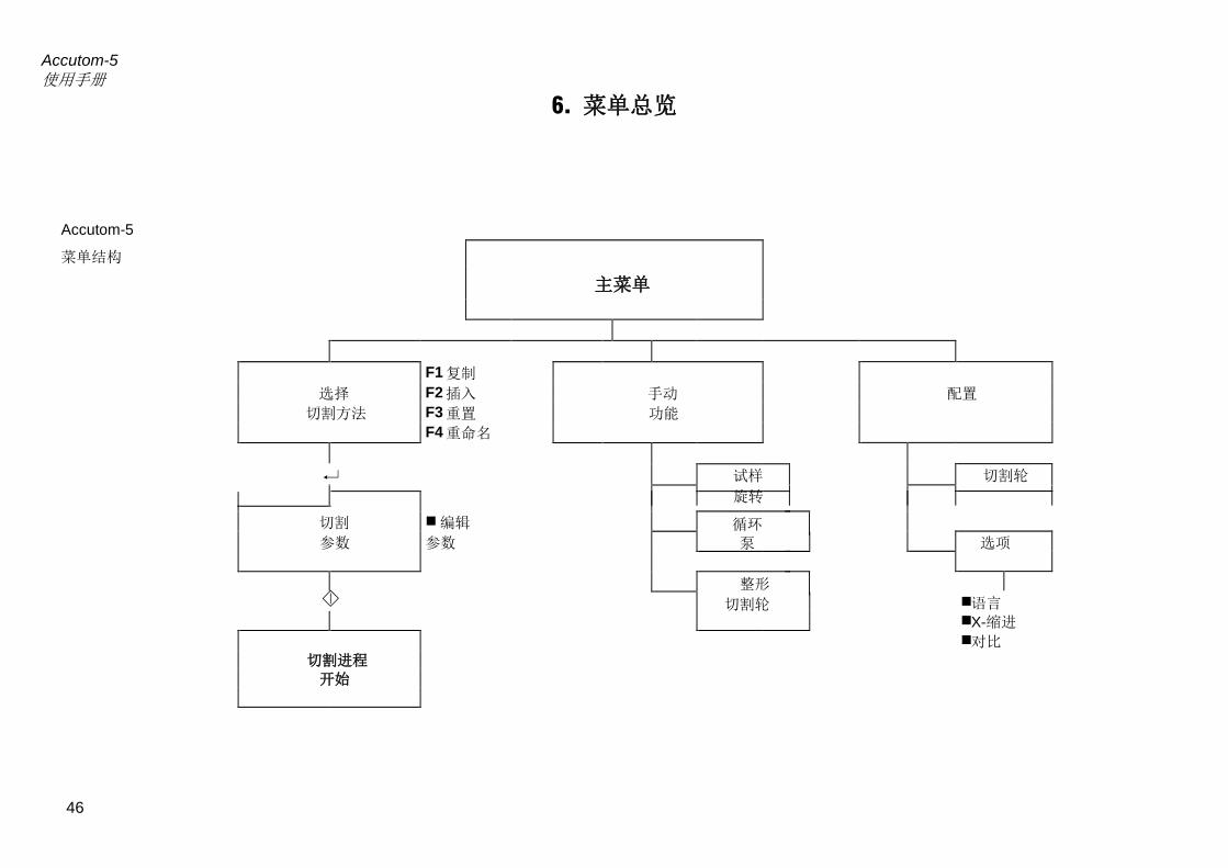
Accutom-5 使用手册
46
6. 菜单总览
Accutom-5 菜单结构
主菜单
F1 复制 选择
S l t F2 插入 手动 配置
切割方法
F3 重置 功能 F4 重命名
试样 切割轮 旋转
切割 编辑 循环 参数 参数 泵 选项
整形 切割轮
语言 X-缩进 对比
切割进程 开始

Accutom-5 使用手册
47
快速参考指南 按下退出键直至出现主菜单。 选择切割方法并按下回车键。 选择需要使用的方法并按下回车键。 按下其中 1 个定位按键 ,转换为 Y 位置界面。 将试样夹具座及试样一起放入试样夹具座头部,并夹紧。 如切割长度已知(如试样直径): 使用定位键将试样正确定位在切割轮前部合适的位置。 按下其中 1 个定位按键 ,转换为 Y 位置界面 按下 F1 键(重置),重置 Y 相对位置。 按下回车键,并使用菜单箭头来调节 Y 停止值。再次按下回
车键确定新数值,或按下退出键取消。 如切割长度事先未知: 使用定位键将试样定位在切割轮前部合适的位置。 按下 F1 键(重置),,重置 X 相对位置。 按下其中 1 个定位按键 ,转换为 Y 位置界面。 按下 F1 键(重置)重置 Y 相对位置。 使用定位键将试样移至右侧——这样即可让试样沿着切割轮方
向移动。 使用定位键将试样沿着切割轮方向移动,直至需要停止的位置。
按下 F2 键(设置停止值),以记录停止位置。 按下 F3 键(移至相对起始位置),将试样移回最初的 Y 位置。 按下其中 1 个定位按键或键,转换为 X 位置界面。 按下 F3 键(移至相对起始位置),将试样移回最初的 X 位置。 按下启动键启动切割程序。
读取切割方法
定位试样
启动程序
显示屏上的“粗”箭头表明
试样夹具座的活动方向。
例:
X 位置
Y 位置

Manual No.: 14947001
Date of Release 15.11.2012
Accutom-5Spare Parts and Diagrams

Accutom-5 Spare Parts and Diagrams
Always state Serial No and Voltage/frequency if you have technical questions or when ordering spare parts.
The following restrictions should be observed, as violation of the restrictions may cause cancellation of Struers legal obligations: Instruction Manuals: Struers Instruction Manual may only be used in connection with Struers equipment covered by the Instruction Manual. Service Manuals: Struers Service Manual may only be used by a trained technician authorised by Struers. The Service Manual may only be used in connection with Struers equipment covered by the Service Manual. Struers assumes no responsibility for errors in the manual text/illustrations. The information in this manual is subject to changes without notice. The manual may mention accessories or parts not included in the present version of the equipment. The contents of this manual is the property of Struers. Reproduction of any part of this manual without the written permission of Struers is not allowed. All rights reserved. © Struers 2012. Struers A/S Pederstrupvej 84 DK-2750 Ballerup Denmark Telephone +45 44 600 800 Telefax: +45 44 600 801
Accutom-5 Spare Parts and Diagrams
1
Spare Parts and Diagrams Table of contents Drawing Cabinet ............................................................................. 14940021D Water Cock ....................................................................... 14940044B Recirculation Tank .......................................................... 14940041G Bottom .............................................................................. 14940051U Back plate .......................................................................... 14940054F Various Parts Wiring Diagram ............................................................... 15013452E Block Diagrams ................................................................ 15013052E
Drawings
Diagrams
The drawings are not to scale. Some of the drawings may contain position numbers
not used in connection with this manual.

Accutom-5 Spare Parts and Diagrams
2

Accutom-5 Spare Parts and Diagrams
3
Spare Part List for Accutom-5
Drawing Pos. Spare Part Cat no.
14940021 Cabinet
15 Seal for cover R4940218
25 Safety switch 2SS00012
70 Cover 14940240
14940044 Water cock
10 Pipe branch 14940420
15 O-ring 7.65-1.78 (10 pcs) RIO17812
20 O-ring 10.82-1.78 (10 pcs) 130MP057
30 Socket for water nozzle R4940422
40 End piece for water nozzle 14940428
60 Water nozzle with internal thread for stopper R4940421
70 Stopper for water nozzle with thread R4940429
14940041 Recirculation Tank
10 Bottom plate 14949005
20 Fitting for Drawer 2JX04230
50 Front plate for Recirculation tank 14949006
60 Foil for recirculation drawer 15010315
90 Tension spring R4940416
14940051 Bottom
20 Rubber foot, with distance (pos. 30) and screw
R4910140
910 Silicone suction hose ø8/ø12 (3 pcs) 14942908
14940054 Back Plate
50 Fuse glass tube 6.3A (10 pcs) 315MP134

Accutom-5 Spare Parts and Diagrams
4
Spare Part List for Accutom-5
Drawing Pos. Spare Part Cat no.
Various Parts
Flange r42, back 14940527
Flange r42, front 14940529
Flange screw M5 427MP012
Backstop with 1 hole 14278017
Backstop with 2 holes 14278016
Pressure spring R2600718
Grate 14940220
Grate, large R4940222
Backstop pin for cut-off wheel flange 14940701
2 pin spanner for cut-off wheel mounting 427MP085
Allen key 2 (10 pcs) RGR00020
Allen key 2,5 (10 pcs) RGR00025
Allen key 3 (10 pcs) RGR00030
Allen key 4 (5 pcs.) RGR00040
Allen key 5 (5 pcs) RGR00050
Set of screws for Specimen Holder for general use (Cat. no. 04946903)
14942906
Debris collection tray 14940221


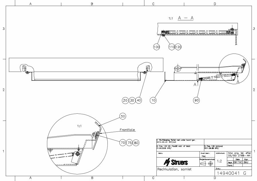


A
A
B
B
C
C
D
D
E
E
F
F
G
G
H
H
I
I
J
J
K
K
L
L
6 6
5 5
4 4
3 3
2 2
1 1
15013452
ACCUTOM 5/50MAINS 200V - 240V/50-60Hz.
KFC
CONTROL BOARD
W11
DRIVE ATY-POS.
DRIVE ATX-POS.
X18
DRIVE ATSAMPLE.
W06
W07 W11
1211
21 22
78VA
9,5V AC
W01
GP
W10
CUTTING MOTOR
CONTROL UNIT
BU
BN
BK
W03
ye/gn
POWER ENTRY
K1
MODUL
W01
CONTACTOR
X-MINLIMIT.
X6:2X6:3X6:4
X6:1
9,5V II24V I
BK
BU BE
BN
YE
WH
BK
RD
X18:1
NC.+15VD/A OUTGND II
9,5V I
BKBU
WH
YEBK
RD
WH
YE
RD
BK
YE/GNA1
BN
SS1 & SS2
SAFETY SWITCH
YE
BK
RD
WH
GN RD
X20
BK
RD
YE
BK
RD
WH
WH
BU
GN
YE
X19
BK
RD
BK RD
WH
BU
GN
YE
YE WH
X21
X15
W04W10
220V
24V AC
W11
1 2 3 4 5 6 7 8 1 2 3 4 5 61 2 3 4
BK GY
YE
BK
BKYE
W05RD2RD1
BK3
BK5
BK2
BK6
X1:1X1:2X1:4
COVER PART
FRONT PANEL
KEYBOARD
BK2
BK5
230V
200V
0V
Q1:7
Q1:5
BU
BU
RD
OR
240V
BN
BN
BN
BU
BN3
F1 F2
0V19V
PCB 12050391
X3:1X3:2X3:3X3:4
WHRD
YE
WH
BK
RD
X8:2X8:3X8:4
X8:1X7:2X7:3X7:4
X7:1
W10
X16
SERVICECOM.
VOLTAGE SELECTOR.
6x0,5
WH
YE
GY
PK
BN
YE
PK
GY
BN
WH
W08
GN/WH RD/WH
J1
J2
X1:6X1:5
POS. 3: 220V
POS. 4: 240V
21V AC
19V AC
BN1
BN2
BN2 BN1
BU2
BU
200-240V/50-60Hz.
FUSES:Accutom 5 : F1 = F2 = 6,3Amp.Accutom 50 : F1 = F2 = 10Amp.
X24:N
X24:N
X23:L
BK1
BU
BU
MB1COOLING FAN
BU
BU
BN
RD
YE
GN
A2
BU2 BN3
BK3BK1
2x0,5W05
BK
RDWH
GN
CI 9
RD2
RD1
Q1
BN = brownRD = red
GN = greenBU = blue
WH = white
BK = black
YE = yellow
VT = violetGY = grey
PK = pink
OR = orange
BE = beige
COLOR CODE:
RO = rose
KEYBOARDSCAN.
:6:4
:3:1
W12
Y01OSCILLATING PUMPCOOLING UNIT
RD
W11
LCDBACKLIGHT CCFT
WH WH
W07
W06
W06 W08
W08
W07
W06
W05
:1
W04
W03
BK
BN
BU
BE
W04
BK YE
X10:3VCC
GND-D
:1
X10:2CH B
:3
NC.X10:1
:2
X10
X10:4CH AX10:5
:4
X2:1 +5V DCX2:2 GND
OUT 24V ACSAFETY SWITCHIN 24V ACSOURCE GND-DX4:1
X4:2X4:3X4:4
CUTTING MOTORX5:1X5:2 N24V AC
X9:3NC.
X9:2 EX. INPUTX9:1
X9:4SOURCE GND-D.
EX. INPUTX11:2
EX. INPUTX11:4X11:3
X11:1NAMUR INPUTSOURCE +5V
SOURCE +5VCOOLING PUMPX12:1
X12:2 N24V+5V DCX13:1
X13:2 GNDGND-SX14:1
SCAN 0X15:1X15:2X15:3X15:4X15:5X15:6X15:7X15:8X15:9X15:10
SCAN 1SCAN 2SCAN 3SCAN 4SCAN 5SCAN 6SCAN 7OUT 1OUT 2
BACKPANEL
RD2
RD1YE BK
RD
BK
BK
X14:2360VRMS
X18:2X18:3X18:4
X19:1X19:2X19:3X19:4
X20:1
X20:3X20:2
X20:4
DISPLAY LCD CCFT240 X 56 DOT.
X16:2TXD0
GNDX16:1
X16:3RXD0
+5V DCX16:4
:1 :2
:4:3
:1 :2
:4:3
:1 :2
:4:3
:1 :2
:4:3
:1 :2
:4:3
:1 :2
:4:3
RD2
W18
:2
:4
:1
:3
:1
:4
:2
:3
MALE FEMALE
CONNECTOR
BK
BN
BU
BE BN
BK
BE
BU
OPTION ATACCUTOM 5.
RD1
CR CR
E
*Note
*Note:
Old VersionGNYEBNWH
|||||
New VersionGNWHRDBK
|||||
SignalChannal AChannal BVCCGND
|||||
Connect toYEWHRDBK
___________ ___________ _________ ___________
Covered withflex.
CrimpTerminal
Rev B: A1, S1, S2, S3 added
Rev C: Connections on A1 changed.
BU1NC.
BU
Rev D: BL renamed to BU.Connections on Z3 swapped.
Rev E: Z3 and X22 removed
WIRING DIAGRAM:
STRUERS A/SPEDERSTRUPVEJ 84DK-2750 BALLERUPDENMARKPHONE:+45 4 600 800
A0
1 1
Wednesday, November 21, 2012
WIRING DIAGRAM:
STRUERS A/SPEDERSTRUPVEJ 84DK-2750 BALLERUPDENMARKPHONE:+45 4 600 800
A0
1 1
Wednesday, November 21, 2012
WIRING DIAGRAM:
STRUERS A/SPEDERSTRUPVEJ 84DK-2750 BALLERUPDENMARKPHONE:+45 4 600 800
A0
1 1
Wednesday, November 21, 2012
EMC FILTEREMC FILTER
X7X7
X1X1
M2M2
77
M3M3
66
M4M4
5533
L1
55mH/4A
L1
55mH/4A
9988 1010
BR01ROTARY OPTICAL ENCODER
BR01ROTARY OPTICAL ENCODER
44
:1:1
NN PEPE LL
X5X5
F2/A2F2/A2
:3:3
A1A1
:A2:A2
L1L1
:5:5
PEPE
:1:1
L2L2
:A1:A1
SO502:2(+)SO502:2(+) S2S2 SO502:1(-)SO502:1(-)
X11X11X14X14
1 2
PEPE
X13X131 2
T1
TRANSFORMATOR
T1
TRANSFORMATOR
:10:10
MD/C
M1
CUTTING MOTOR
MD/C
M1
CUTTING MOTOR
12
:1:1
L1:1L1:1
L1:2L1:2
:6:6
:5:5
:4:4:2:2
X3X3
X12X121 2
:1:1
:1:1
X6X6
DIODEDIODE
:4:4
X02X02
1
2
X25X25X26X26
X4X4
J3J3
J4J4
X8X8
NAMURBQ1NAMURNAMURBQ1NAMUR
1
2
DISPLAY
X17
DB0DB1DB2DB3DB4DB5DB6DB7
GND-S++GND++5VV0
LCDWRLCDCE
NCRESET
LCDRDC/D
6X8RVERS
Z2Z2
X9X9

1
1
2
2
3
3
4
4
5
5
6
6
7
7
8
8
9
9
10
10
11
11
12
12
A A
B B
C C
D D
E E
F F
24V
0V
9,5V
0V
78VA
DRIVE AT Y-POS.
DRIVE AT X-POS.
2x8
SIGN. A
SIGN. B
+5V
POWER
SUPPLY
+5V
0V
15013052
8 OUT
X-MIN. LIMIT.:
2 IN
NC.
LCD240 X 56 DOTOPTREX50316 CCFT
A2
1
3
5
2
4
6
Q1
240V
220V
19V
KEYBOARD
L1
BL
BL
BN3
BN
BL
BKW03
GY
YE
BN
WH
BK
W06
W07
BE
BK
BK
YE
WH
YE
BK
RD
bk
ye
rd
wh
BL2
BK5 BK6
BR01ROTARY OPTICAL
ENCODERS AT Y-POS.
W08
DRIVE AT SAMPLE.
0V
200V
230V
10
9
8
7
5
6
VOLTAGE
SELECTOR
INSERT
SAFETY GUARD CLOSED
CUTTING MOTOR.
COOLING WATER.
BK
RD
RD
RD
RD/WH
GN/WH
GN
RD
BN
BN
RD
OR
BU
BN
BL
3
4
M
M
M
24V
9,5V
2x7,83mH 2x7,83mH
0,036mH0,68µF
0,47µF
2x10nF
2x5,5nF
KFC / KFC
BN3
BN4
X19:8
X19:7
21V
OV
21V
J1
J2 J4
BK3
BK1
ACCUTOM 5/50
FILE NAME: 5013052.DSN
#
230V BLOCK- / WIRINGDIAGRAM
POWER ENTRY MODULE
RD2
RD1W12
W05
EX. INPUT
+5VDC
GND
EXTRA +5V DC OUTPUTFOR COOLING FAN
GND
SERVICE COM.RXD0
TXD0
+5V DC
EXTRAINPUTS.
W04BN
BL
CUTTING MOTORREADY FOR RUN
W10
W01
W11
BK2
EX. INPUT
EX. INPUT
EX. INPUT
EX. INPUT
EX. INPUT
wh
rd
ye
bk
wh
rd
ye
bk
WH
BL
GN
YE
WH
BL
GN
YE
EXTRAINPUT.
X21:1
X21:2
X21:3
X21:4
A1
X18:1
X18:2
X18:3
X18:4
X19:1
X19:2
X19:3
X19:4
X20:3
X20:4
X20:2
X20:1
WH
GN
RD
BK
BE
BK
BN
BL
POWERSUPPLY
F1
F2
D/A-CONVERTER:CONTROL SIGNALCUTTING MOTOR
COOLINGFAN 1
COOLINGFAN 2
AC POWEROUTPUT
AC POWEROUTPUT
SERVICECOM
ROTATIONDRIVER
X-POSITIONDRIVER
Y-POSITIONDRIVER
LCDDISPLAYDRIVEROUTPUT
CCFTOUTPUT
ENCODERINPUT
SAFETYSWITCHREAD
SAFETYSWITCHPOWER
EXTRAINPUTS(SWITCH)
NAMURSIGN. IN
EXTRAINPUT(NAMUR)
KEYBOARDSCANWITH BEEPER
X25 / X26 : 3
X25 / X26 : 1
X25 / X26 : 4
X25 / X26 : 2
W18
OPTION ATACCUTOM 5.
CR
WH
WH
CR
F3
*Note:Old VersionGNYEBNWH
|||||
New VersionGNWHRDBK
|||||
SignalChannal AChannal BVCCGND
|||||
Connect toYEWHRDBK
___________ ___________ ___________ ___________*Note
E
Covered withflex.
CrimpTerminal
FUSES:Accutom 5 : F1 = F2 = 6,3Amp.Accutom 50 : F1 = F2 = 10Amp.
Rev B : Motor Control. S1, S2, S3 added.
Rev C : Motor Control. Connections changed
Rev D : Z1 changed to Z2
BK2
BK6
Rev E : Z3 and X22 removed
BLOCK AND WIRING DIAGRAM:
STRUERS A/SVALHOEJS ALLÉ 176DK-2610 ROEDOVREDENMARKPHONE:+45 3670 3500
A1
1 1Wednesday, November 21, 2012
BLOCK AND WIRING DIAGRAM:
STRUERS A/SVALHOEJS ALLÉ 176DK-2610 ROEDOVREDENMARKPHONE:+45 3670 3500
A1
1 1Wednesday, November 21, 2012
BLOCK AND WIRING DIAGRAM:
STRUERS A/SVALHOEJS ALLÉ 176DK-2610 ROEDOVREDENMARKPHONE:+45 3670 3500
A1
1 1Wednesday, November 21, 2012
T1
TRANSFORMATOR
T1
TRANSFORMATOR
DIODEDIODE
X1:LX1:L
X1:PEX1:PE
S1
MAINS SWITCH
S1
MAINS SWITCH
S1S1
K1K1
NAMU
R
BQ1
NAMUR
NAMU
R
BQ1
NAMUR
X1:NX1:N
CONTROL BOARD.
J3
X1:1
X1:2
X1:4
X1:6
X1:5
X17:12
X17:11
X17:10
X17:9
X17:8
X17:13
X17:14
X17:15
X17:16
X17:17
X17:18
X17:19
X17:20
X6:1
X6:2
X6:3
X6:4
X7:1
X7:2
X7:3
X7:4
X8:1
X8:2
X8:3
X8:4
X10:5
X10:4
X10:3
X10:2
X10:1
X4:2
X4:4
X4:1
X4:3
X11:3
X11:1
X11:2
X15:10
X15:9
X15:8
X15:7
X15:6
X15:5
X15:4
X15:3
X15:2
X15:1
X12:1
X5:2
X5:1
X12:2
X13:2
X13:1
X3:1
X3:2
X3:3
X17:3
X17:2
X17:1
X14:1
X14:2
X17:4
X17:5
X17:6
X3:4
X16:1
X16:2
X16:3
X16:4
X2:2
X2:1
X11:4
X9:1
X9:2
X9:3
X9:4
X17:7
SS1
SAFETY SWITCH
SS1
SAFETY SWITCH
F2 #F2 #
F1 #F1 #
MB1
COOLING-FAN
MB1
COOLING-FAN
SS2
SAFETY SWITCH
SS2
SAFETY SWITCH
TASTATUR
TASTATUR.SCH
X2
X1
Y8
Y7
Y6
Y5
Y4
Y3
Y2
Y1
Y-ENCODER
ENCODER.SCH
LCD MODUL
LCD 240X56 CCFT
RVERS
6X8
DB0
RESET
VSS
NC
DB7
DB6
DB5
DB4
DB3
DB2
DB1
V0
VCC
FG
C/D
LCDCE
LCDRD
LCDWR
CCFT
CCFT
MOTOR CONTROL
PA00412.SCH
L1
A1
SO502:1(-)
S2
SO502:2(+)
PE
L2
F2/A2
M4
STEPMOTOR
M4
STEPMOTOR
M3
STEPMOTOR
M3
STEPMOTOR
M2
STEPMOTOR
M2
STEPMOTOR
55mH/4Amp
DROSSEL SPOLE
55mH/4Amp
DROSSEL SPOLE
Z2Z2 EMC FILTEREMC FILTER
CONTACTORCONTACTOR
M
D/C
M1
CUTTING MOTORM
D/C
M1
CUTTING MOTOR
K1
CONTACTOR
K1
CONTACTOR
YO1
OSCILLATING PUMP
YO1
OSCILLATING PUMP

494 Accutom5 14.01.2014 494C_2014
English Declaration of Conformity Manufacturer Struers A/S
Pederstrupvej 84 DK-2750 Ballerup, Denmark Telephone +45 44 600 800
Herewith declares that Product Name: Accutom-5 Type No: 494 Machine Type: Precision cut-off machine
is in conformity with the provisions of the following directives:
Safety of Machinery 2006/42/EC according to the following standard(s): EN ISO 12100:2011, EN60204-1:2006/AC:2010.
Low Voltage Directive 2006/95/EC according to the following standard(s): EN60204-1:2006/AC:2010.
EMC-Directive 2004/108/EC according to the following standard(s): EN61000-6-1:2007, EN61000-6-3:2007/A1:2011.
RoHS 2011/64/EC according to the following standard(s): EN 50581:2012.
Supplementary Information
The equipment complies with the American standards: FCC part 15, subpart B and UL508.
The above has been declared according to the global method, module A
Date: 14.01.2014 Christian Skjold Heyde, Vice President, R & D and Production, Struers A/S
Dansk Overensstemmelseserklæring Fabrikant Struers A/S
Pederstrupvej 84 DK-2750 Ballerup, Danmark Telefon 44 600 800
erklærer herved, at Produktnavn: Accutom-5 Type nr.: 494 Maskintype: Præcisionsskæremaskine
er i overensstemmelse med følgende EU-direktiver:
Maskindirektivet 2006/42/EF efter følgende norm(er): EN ISO 12100:2011, EN60204-1:2006/AC:2010.
Lavspændingsdirektivet 2006/95/EF efter følgende norm(er): EN60204-1:2006/AC:2010.
EMC-direktivet 2004/108/EF efter følgende norm(er): EN61000-6-1:2007, EN61000-6-3:2007/A1:2011.
RoHS 2011/64/EC efter følgende norm(er): EN 50581:2012.
Supplerende oplysninger
Endvidere overholdes de amerikanske normer: FCC part 15, subpart B og UL508
Ovenstående overensstemmelse(r) er erklæret iflg. den globale metode, modul A
Dato: 14.01.2014 Christian Skjold Heyde, Vice President, Udvikling og Produktion, Struers A/S

Deutsch Konformitätserklärung Hersteller Struers A/S
Pederstrupvej 84 DK-2750 Ballerup, Danmark Telefon +45 44 600 800
erklärt hiermit, daß Produktname: Accutom-5 Typennr.: 494 Maschinenart: Präzisionstrennmaschine
konform ist mit den einschlägigen EG-Richtlinien
Sicherheit der Betriebsanlage
2006/42/EG gemäß folgender Normen: EN ISO 12100:2011, EN60204-1:2006/AC:2010.
Niederspannungs -Direktive
2006/95/EG EG gemäß folgender Normen: EN60204-1:2006/AC:2010.
EMC-Direktive 2004/108/EG gemäß folgender Normen: EN61000-6-1:2007, EN61000-6-3:2007/A1:2011.
RoHS 2011/64/EC gemäß folgender Normen: EN 50581:2012.
Ergänzungs-information Die Maschine entspricht ebenfalls den amerikanischen FCC Normen: FCC Teil 15, Abschnitt B und UL508
Die obenstehende Konformität ist in Folge der globalen Methode, Modul A erklärt
Datum: 14.01.2014 Christian Skjold Heyde, Stellvertretender Geschäftsführer, Entwicklung und Produktion, Struers A/S
Français Déclaration de conformité Fabricant Struers A/S
Pederstrupvej 84 DK-2750 Ballerup, Denmark Téléphone +45 44 600 800
Déclare ci-après que Nom du produit: Accutom-5 Type no: 494 Type de machine: Machine pour le tronçonnage de précision
est conforme aux dispositions des Directives CE suivantes:
Sécurité des machines 2006/42/CE conforme aux normes suivantes: EN ISO 12100:2011, EN60204-1:2006/AC:2010.
Directive de basse tension
2006/95/CE conforme aux normes suivantes: EN60204-1:2006/AC:2010.
Directive EMC 2004/108/CE conforme aux normes suivantes: EN61000-6-1:2007, EN61000-6-3:2007/A1:2011.
RoHS 2011/65/UE conforme aux normes suivantes: EN 50581:2012.
Informations supplémentaires
L’équipement est conforme aux standards américains: FCC paragraphe 15, sous-paragraphe B et UL508.
La déclaration ci-dessus a été faite d’après la méthode globale, module A
Date: 14.01.2014 Christian Skjold Heyde, Vice- President, R & D et Production, Struers A/S

Common features of Accutom-5/-50- Positioning accuracy of 5 µm- Pre-set, constant feed speed (0.005 to 3 mm/sec)- Adjustable force limit- Sample rotation or oscillation- Variable cut-off wheel speed up to 3,000 rpm- Menu control and digital read-out- Built-in cut-off wheel list- Database with user-definable cutting methods- Built-in recirculation cooling unit- Enclosed cutting chamber with safety switch
Common application areas:Precise and deformation-free cutting of:- Metals- Electronic components- Ceramics- Composites- Crystals- Sintered carbides- Minerals- Fibre reinforced materials- Biomaterials (teeth and bones)
Accutom-5Automatic precision
cut-off machine
Accutom-50... and grinding machine
Additional features of Accutom-50- Serial cutting of slices (Multi-cut)- Grinding of thin sections- Target grinding in components- Variable cut-off wheel speed up to 5,000 rpm- Database for both cutting and grinding methods- Improved menu control
Additional application areas:- Precise serial cutting of all materials- Thin sections of minerals- Thin sections of ceramics- Target grinding in components
Accutom
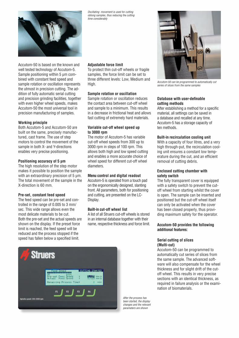
Accutom-50 is based on the known and well tested technology of Accutom-5. Sample positioning within 5 µm com-bined with constant feed speed and sample rotation or oscillation represents the utmost in precision cutting. The ad-dition of fully automatic serial cutting and precision grinding facilities, together with even higher wheel speeds, makes Accutom-50 the most universal tool in precision manufacturing of samples.
Working principle Both Accutom-5 and Accutom-50 are built on the same, precisely manufac-tured, cast frame. The use of step motors to control the movement of the sample in both X- and Y-directions enables very precise positioning.
Positioning accuracy of 5 µmThe high resolution of the step motor makes it possible to position the sample with an extraordinary precision of 5 µm.The total movement of the sample in the X-direction is 60 mm.
Pre-set, constant feed speedThe feed speed can be pre-set and con-trolled in the range of 0.005 to 3 mm/sec. This wide range allows even the most delicate materials to be cut.Both the pre-set and the actual speeds are shown on the display. If the preset force limit is reached, the feed speed will be reduced and the process stopped if the speed has fallen below a specified limit.
Adjustable force limitTo protect thin cut-off wheels or fragile samples, the force limit can be set to three different levels: Low, Medium and High.
Sample rotation or oscillationSample rotation or oscillation reduces the contact area between cut-off wheel and sample to a minimum. This results in a decrease in frictional heat and allows fast cutting of extremely hard materials.
Variable cut-off wheel speed up to 3000 rpmThe motor of Accutom-5 has variable cut-off wheel speeds from 300 up to 3000 rpm in steps of 100 rpm. This allows both high and low speed cutting and enables a more accurate choice of wheel speed for different cut-off wheel diameters.
Menu control and digital readoutAccutom-5 is operated from a touch pad on the ergonomically designed, slanting front. All parameters, both for positioning and cutting, are presented on the LC- Display.
Built-in cut-off wheel listA list of all Struers cut-off wheels is stored in an internal database together with their name, respective thickness and force limit.
Database with user-definable cutting methodsAfter establishing a method for a specific material, all settings can be saved in a database and recalled at any time. Accutom-5 has a storage capacity of ten methods.
Built-in recirculation cooling unitWith a capacity of four litres, and a very high through-put, the recirculation cool-ing unit ensures a constant low temp-erature during the cut, and an efficient removal of cutting debris.
Enclosed cutting chamber with safety switchThe fully transparent cover is equipped with a safety switch to prevent the cut-off wheel from starting whilst the cover is open. The sample can be inserted and positioned but the cut-off wheel itself can only be activated when the cover has been closed properly, thus provi-ding maximum safety for the operator.
Accutom-50 provides the following additional features:
Serial cutting of slices (Multi-cut)Accutom-50 can be programmed to automatically cut series of slices from the same sample. The advanced soft-ware will also compensate for the wheel thickness and for slight drift of the cut-off wheel. This results in very precise sections with an identical thickness, as required in failure analysis or the exami-nation of biomaterials.
After the process has been started, the display changes and the relevant parameters are shown
Oscillating movement is used for cutting oblong samples, thus reducing the cutting time considerably
Accutom-50 can be programmed to automatically cut series of slices from the same samples

Grinding of thin sectionsThe thickness ground during each differ-ent operation associated with a thin sec-tion can be easily adjusted or even saved in different grinding methods. After grind-ing the glass plate to the precise thick-ness, the position of the sample holder is set to zero. Thereafter the thickness of the thin section is entered directly.
Target grinding in componentsWhen the precise position of a com-ponent within a sample is known, Accutom-50 can be programmed to grind down to precisely that position. The position can be adjusted in steps of 5 µm.
Variable cut-off wheel speed up to 5000 rpmThe variable cut-off wheel speed can be adjusted from 300 up to 5000 rpm in steps of 100 rpm. This grants even higher precision as the drift of the cut- off wheel is reduced because of the higher speed. Also, the feed speed can be increased without experiencing any deterioration in the high quality of the cut surface.
Database for both cutting and grinding methodsAccutom-50 is equipped with a data-base capable of storing 20 cutting and 10 grinding methods.
Improved menu control Subsequent menus for the selection of cutting or grinding parameters greatly facilitate the operation. Together with the larger display the new menu control improves the user-friendliness of Accutom-50.
Cut-off wheelsAs Accutom-50 works with program-mable constant feed speeds, all types of cut-off wheels, including abrasive wheels, can be used.
Struers offer a large variety of Diamond, CBN, Al2O3 and SiC cut-off wheels cove-ring all possible applications. Also, saw blades for the cutting of very soft metals or plastics can be used on Accutom-5/50 due to the cover with the safety switch.
Cup wheelsTwo different types of cup wheels, resin and metal bonded, are available for grinding on Accutom-50.
Specimen holdersAll specimen holders for Accutom-5/-50 are provided with a dovetail plate. This means that the samples can be clamped into the sample holder outside the cutting chamber, and then easily inserted into the dovetail fixture of Accutom-5/-50.
Grinding on Accutom-50 can be carried out in two different ways: The grinding operation can be stopped at a specified position, or a well-defined amount of material can be removed
A wide range of specimen holders can be used on Accutom machines

AuSTrAlIA & NEW ZEAlANDStruers Australia27 Mayneview StreetMilton QLD 4064AustraliaPhone: +61 7 3512 9600Fax: +61 7 3369 [email protected]
BElGIQuE (Wallonie)Struers S.A.S.370, rue du Marché RollayF- 94507 Champigny sur Marne CedexTéléphone +33 1 5509 1430 Télécopie +33 1 5509 [email protected]
BElGIuM (Flanders)Struers GmbH NederlandElektraweg 53144 CB MaassluisTelefoon: +31 (10) 599 7209Fax: +31 (10) [email protected]
CANADAStruers ltd.7275 West Credit AvenueMississauga, Ontario L5N 5M9Phone +1 905-814-8855Fax +1 [email protected]
CHINAStruers ltd.No. 1696 Zhang Heng RoadZhang Jiang Hi-Tech ParkShanghai 201203, P.R. ChinaPhone +86 (21) 6035 3900Fax +86 (21) 6035 [email protected]
CZECH rEPuBlICStruers GmbHOrganizační složkaHavlíčkova 361CZ-252 63 Roztoky u PrahyPhone +420 233 312 625Fax: +420 233 312 [email protected]
DEuTSCHlAND Struers GmbHCarl-Friedrich-Benz-Straße 5D- 47877 WillichTelefon +49 (0) 2154 486-0Fax +49 (0) 2154 486-222 [email protected]
FrANCEStruers S.A.S.370, rue du Marché RollayF-94507 Champigny sur Marne CedexTéléphone +33 1 5509 1430 Télécopie +33 1 5509 [email protected]
IrElANDStruers ltd.Unit 11 Evolution@ AMPWhittle Way, CatcliffeRotherham S60 5BLTel: +44 0845 604 6664Fax: +44 0845 604 [email protected]
ITAlYStruers ItaliaVia Monte Grappa 80/420020 Arese (MI)Tel. +39-02/38236281Fax +39-02/[email protected]
JAPANMarumoto Struers K.K.Takara 3rd Building18-6, Higashi Ueno 1-chomeTaito-ku, Tokyo 110-0015 Phone +81 3 5688 2914 Fax +81 3 5688 [email protected]
NETHErlANDSStruers GmbH NederlandElektraweg 53144 CB MaassluisTelefoon: +31 (10) 599 7209Fax: +31 (10) [email protected]
ÖSTErrEICHStruers GmbHZweigniederlassung ÖsterreichBetriebsgebiet Puch Nord 85412 PuchTelefon: +43 6245 70567Fax: +43 6245 [email protected]
POlANDStruers Sp. z o.o.Oddział w Polsceul. Jasnogórska 4431-358 KrakówPhone +48 12 661 20 60Fax +48 12 626 01 46 [email protected]
rOMANIAStruers GmbHSucursala SibiuStr.Scoala de Inot, nr. 18RO-550005 SibiuPhone +40 269 244 558 Fax +40 269 244 [email protected]
SCHWEIZStruers GmbHZweigniederlassung SchweizWeissenbrunnenstraße 41CH-8903 Birmensdorf Telefon +41 44 777 63 07 Fax +41 44 777 63 [email protected]
SINGAPOrEStruers Singapore627A Aljunied Road, #07-08 BizTech CentreSingapore 389842Phone +65 6299 2268 Fax +65 6299 [email protected]
SuOMIStruers SuomiKalevankatu 4300180 HelsinkiPuhelin +358 (0)207 919 430Faksi +358 (0)207 919 [email protected]
SWEDENStruers SverigeEkbacksvägen 22168 69 BrommaTelefon +46 (0)8 447 53 90 Telefax +46 (0)8 447 53 [email protected]
uNITED KINGDOMStruers ltd.Unit 11 Evolution @ AMPWhittle Way, CatcliffeRotherham S60 5BLTel: +44 0845 604 6664Fax: +44 0845 604 [email protected]
uSAStruers Inc.24766 Detroit RoadWestlake, OH 44145-1598Phone +1 440 871 0071 Fax +1 440 871 [email protected]
Struers A/SPederstrupvej 84 DK-2750 Ballerup, Denmark Phone +45 44 600 800Fax +45 44 600 [email protected] www.struers.com
Struers’ equipment is in conformity with the provisions of the applicable International Directives and their appurtenant Standards. (Please contact you local supplier for details)
Struers’ products are subject to constant product development. Therefore, we reserve the right to introduce changes in our products without notice.
Technical data Cutting Accutom-5 Accutom-50
Cutting speed: 300-3000 rpm Cutting speed: 300-5000 rpm (adjustable in steps of 100 rpm) (adjustable in steps of 100 rpm) Feed speed: 0.005-3.000 mm/s Feed speed: 0.005-3.000 mm/s (adjustable in steps of 0.005 mm/s) (adjustable in steps of 0.005 mm/s) Max.pos.speed: Y=13 mm/s X=10 mm/s Max.pos.speed: Y=13 mm/s X=10 mm/s Force limits: low: approx. 20 N Force limits:low: approx. 20 N medium: approx. 40 N; medium: approx. 40 N; high: approx. 60 N high: approx. 60 N
Pos. range Y direction: 105 mm (precision 0.1 mm), X direction: 60 mm (precision 0.005 mm)
Sample size Max length of cut-off sample: 30 mm, 140 mm at ø20 mm Max length of sample to be clamped: 225 mm Max sample cross section: ø127 mm cut-off wheel and ø40 mm (without rotation) ø42 mm flange: ø80 mm (with rotation) ø152 mm cut-off wheel and ø50 mm (without rotation) ø42 mm flange: ø100 mm (with rotation)
recirculation Contents: 4 l Contents: 4 l cooling unit Flow: 800 ml/min Flow: 800 ml/min
Motor 370 W at 3000 rpm 550 W at 5000 rpm
Software and Display: 4 x 40 characters Display: 4 x 40 characters electronics Controls: touch pad Controls: touch pad Database: 10 cutting methods Database: 20 cutting and 10 grinding methods
Power supply 1-3 x 200-240 V / 50/60 Hz
Dimensions Width: 510 mm / 20", Depth: 700 mm / 27.6", Height: 270 mm / 10.6", and weight Weight: 45 kg / 99 lbs
11.2012B / 62115010. Printed in Denmark
AccessoriesSpecimen holders Three jaw-chuck 05036919 For general use. Vice type with max. opening 60 mm 04946903 For round or square specimens. Teardrop type with max. opening ø 40 mm / ø 1½” 04946904 For irregular specimens, with 7 screws. Max. width 40 mm / 1½” 04946905 With goniometer 04276911 For adhering specimens 04276912 With ceramic vacuum chuck for thin sections 04276913 For small specimens. Vice type 04276915 For long specimens. With double parallel vice 04946909 For cylindrical specimens, max. dia. 40 mm 04946907
Joints to be mounted between the dovetail and the specimen holder Tilting joint with max. angle ±10° 04946906 Angling joint with max. angle +30/-90° 04946908
Base Plate With dovetail. For mounting of other types of specimen holders 04276914
Flange Sets For cut-off wheels, 65 mm dia., to achieve highest precision 04946902 For cup wheels, only to be used on Accutom-50 05016901
Additive for Cooling Fluid For Recirculation Cooling Unit. To protect the machine from corrosion, 1 l 49900045 and to improve cutting and cooling qualities 5 l 49900046
See special brochure for more information about cut-off wheels.
Specifications Cat. no.
Accutom-5 Precision cut-off machine with variable speed. Automatic feeding with electronic control of feed speed. 04946227 Motorised positioning system and digital read-out, with built-in sample rotation and oscillation. Complete with recirculation cooling unit, flange sets 42 mm dia. and specimen holder (04946903). Cut-off wheels, additive for cooling fluid and additional specimen holders are ordered separately.
Accutom-5 Precision cut-off machine with variable speed. Automatic feeding with electronic control of feed speed. 04946127 Motorised positioning system and digital read-out. Complete with recirculation cooling unit, flange sets 42 mm dia. and specimen holder (04946903). Without built-in sample rotation and oscillation. Cut-off wheels, additive for cooling fluid and additional specimen holders are ordered separately.
Accutom-50 Precision cut-off and grinding machine with variable speed. Equipped with Multi-cut feature. 05016227 Automatic feeding with electronic control of feed speed. Motorised positioning system and digital read-out, with built-in sample rotation and oscillation. Complete with recirculation cooling unit, flange sets 42 mm dia. and specimen holder (04946903). Cut-off wheels, additive for cooling fluid, cup wheels, additional specimen holders, and the flange set for cup-wheels are ordered separately.

Allgemeine Funktionsmerkmale von Accutom-5/50- Positionierung auf 5 µm genau- Konstante, einstellbare Vorschubgeschwindigkeit (0,005 bis 3 mm/s)- Einstellbare Kraftgrenzwerte- Rotation oder Oszillation der Probe- Variable Drehgeschwindigkeit der Trennscheibe bis 3000 U/min- Menüsteuerung und Digitalanzeige- Integrierte Liste mit Trennscheiben- Datenbank mit benutzerdefinierbaren Trennmethoden- Eingebaute Umlaufkühleinheit- Geschlossene Trennkammer mit Sicherheitsvorrichtung
Anwendungsbereiche:Präzises und verformungsfreies Trennen von:- Metallen- Elektronischen Komponenten- Keramik- Verbundwerkstoffen- Kristallen- Hartmetallen- Mineralien- Faserverstärkten Materialien- Medizinischen Materialien (Zähne und Knochen)
Accutom-5Automatische
Präzisionstrennmaschine
Accutom-50... und
Präzisionsschleifmaschine
Zusätzliche Funktionsmerkmale von Accutom-50- Serielles Trennen von Scheiben (Mehrfachtrennen)- Schleifen von Dünnschliffen- Zielschleifen in Komponenten- Variable Drehzahl der Trenn - scheibe bis maximal 5000 U/min- Datenbank sowohl für Trenn- als auch Schleifverfahren- Verbesserte Menüsteuerung
Zusätzliche Anwendungsbereiche:- Präzises serielles Trennen aller Materialien- Mineralogische Dünnschliffe- Keramische Dünnschliffe- Zielschleifen in Komponenten
Accutom

Accutom-50 baut auf der bekannten undhinreichend getesteten Technologie von Accutom-5 auf. Die Positionierungs-mög-lichkeit der Probe innerhalb 5 µm sowie die konstante Vorschubgeschwin-digkeit und Probenrotation oder Oszillation stel-len zur. Zeit das Nonplusultra beim Prä-zisionstrennen dar. Accutom-50 kann zu-sätzlich vollautomatisch Serienschnit-te herstellen und zum Präzisionsschlei-fen verwendet werden. Zusammen mit der noch höheren Scheibengeschwindigkeit stellt Accutom-50 die universellste Maschine zur Präzisionsherstellung von Proben dar.
FunktionsprinzipSowohl Accutom-5 als auch Accutom-50 sind auf den gleichen, präzisionsgefer-tigten gegossenen Rahmen aufgebaut. Da Schrittmotoren verwendet werden, um die Probenbewegung in X- und Y-Richtung zu steuern, kann in Schritten von 5 µm positi-oniert werden.
Positioniergenauigkeit von 5µmBedingt durch die hohe Auflösung des Schrittmotors kann die Probe mit einer außergewöhnlichen Genauigkeit von 5 µm positioniert werden. Die Probe kann in X-Richtung maximal um 60 mm bewegt werden.
Konstante, voreingestellte VorschubgeschwindigkeitDie Vorschubgeschwindigkeit kann im Be-reich von 0,005 bis 3 mm/s voreingestellt und gesteuert werden. Aufgrund dieses großen Bereichs können selbst äußerst empfindliche Materialien getrennt werden.
Sowohl die voreingestellte als auch die tat-sächliche Vorschubgeschwindigkeit wer-den auf dem Display angezeigt. Wenn der voreingestellte Wert der Kraftgrenze er-reicht wird, verringert sich die Vorschubge-schwindigkeit, und der Prozeß wird abge-brochen, sofern die Geschwindigkeit unter einen spezifizierten Grenzwert gefallen ist.
Einstellbare KraftgrenzeUm dünne Trennscheiben oder empfind-liche Proben zu schützen, ist es möglich, die Kraftgrenze auf drei verschiedene Werte einzustellen: Niedrig, Mittel, Hoch).
Rotation oder Oszillation der ProbeDurch die Rotation oder Oszillation der Probe wird die Kontaktfläche zwischen Trennscheibe und Probe auf ein Minimum reduziert. Diese Tatsache führt zu einer Absenkung der Reibungswärme, und ermöglicht das Trennen extrem harter Materialien.
Variable Drehgeschwindigkeit der Trennscheibe bis maximal 3000 U/minDer Motor des Accutom-5 besitzt eine va-riable Trennscheibengeschwindigkeit von 300 bis 3000 U/min in Schritten von 100 U/min. Auf diese Weise ist sowohl ein Trennvorgang im hohen und niedrigen Geschwindigkeitsbereich als auch eine exakte Wahl der Scheibengeschwindigkeit für verschiedene Trennscheibendurchmes-ser möglich.
Menüsteuerung und DigitalanzeigeAccutom-5 wird über ein Sensor-tasten-feld auf der ergonomisch geformten, ab-geschrägten Vorderseite bedient. Alle
Parameter für die Positionierung und den Trennvorgang werden auf dem LC-Display angezeigt.
Integrierte Liste mit TrennscheibenEine Liste aller Trennscheiben von Struers ist in einer internen Datenbank gespeichert, die ebenfalls die Bezeichnung, die jeweilige Dicke und die zulässige Kraftgrenze enthält.
Datenbank mit benutzerdefinierbaren TrennmethodenNachdem eine Methode für ein spezi-fisches Material eingerichtet worden ist, können alle Einstellungen in einer Daten-bank gespeichert und jederzeit wieder ab-gerufen werden. Accutom-5 verfügt über Speicherkapazität für zehn Methoden.
Integrierte UmlaufkühleinheitDie Umlaufkühlung verfügt über eine Ka-pazität von vier Litern und einen sehr ho-hen Durchsatz und sorgt auf diese Weise während des Trennvorgangs für eine kon-stante niedrige Temperatur und eine effizi-ente Abführung der Späne.
Geschlossene Trennkammer mit SicherheitsvorrichtungDer vollständig transparente Deckel ist mit einer Sicherheitsvorrichtung ausgerüstet, um zu verhindern, daß die Trennscheibe versehentlich eingeschaltet wird, wenn der Deckel geöffnet ist. Die Probe kann ein-gesetzt und positioniert werden, aber die Trennscheibe selbst kann nur dann einge-schaltet werden, wenn der Deckel richtig geschlossen ist, so daß der Benutzer ma-ximal geschützt wird.
Accutom-50 bietet zusätzlich die folgenden Funktionsmerkmale:
Serielles Trennen von Scheiben (Mehrfachtrennen)Accutom-50 läßt sich so programmieren, daß Serien von Scheiben von derselben Probe automatisch abgetrennt werden können. Die raffinierte Software gleicht
Nachdem der Vorgang gestartet wurde wechselt die Bildschirmdarstellung und die relevanten Werte werden angezeigt
Bei länglichen Proben wird die Probe oszilliert, wodurch die Trennzeit wesentlich verkürzt wird
Accutom-50 läßt sich so programmieren, daß Serien von Scheiben von derselben Probe automatisch abgetrennt werden können

auch Scheibendicke und geringfügige Ab-weichung der Trennscheibe aus. Auf die-se Weise lassen sich präzise Schnitte mit identischer Dicke herstellen, so wie es die Schadensanalyse oder die Untersuchung von medizinischen Materialien erfordert.
Schleifen von DünnschliffenDie Dicke, die während aller unterschied-lichen Vorgänge in Zusammenhang mit Dünnschliffen abgeschliffen wird, läßt sich ganz einfach einstellen oder sogar in den verschiedenen Schleifverfahren speichern. Nachdem die Glasplatte auf die genaue Dicke geschliffen worden ist, wird die Po-sition des Probenhalters auf Null gestellt. Anschließend wird die Dicke des Dünn-schliffes direkt eingegeben.
Zielschleifen in KomponentenIst die genaue Position einer Komponente in einer Probe bekannt, kann Accutom-50 so programmiert werden, daß bis zu die-ser Position heruntergeschliffen wird. Die Position kann in Schritten von 5 µm ein-gestellt werden.
Variable Drehzahl der Trennscheibe bis maximal 5000 U/minDie variable Drehzahl der Trennscheibe läßt sich von 300 bis maximal 5000 U/min in Schritten von 100 U/min einstellen.
Auf diese Weise kann eine noch höhere Genauigkeit gewährleistet werden, da sich die Abweichung der Trennscheibe wegen der höheren Drehzahl verringert. Darüber hinaus kann die Vorschubgeschwindigkeit gesteigert werden, ohne daß sich die hohe Qualität der Trennfläche verschlechtert.
Datenbank sowohl für Trenn- als auch SchleifverfahrenAccutom-50 wurde mit einer Daten-bank ausgerüstet, in der 20 Trenn- und 10 Schleifverfahren gespeichert werden können.
Verbesserte MenüsteuerungDurch Untermenüs, über die Trenn- oder Schleifparameter ausgewählt werden können, wird die Anwendung erheblich erleichtert. Zusammen mit dem größeren Display verbessert die neue Menüsteue-rung die Benutzerfreundlichkeit des Accutom-50.
TrennscheibenDa Accutom-50 mit programmierbaren konstanten Vorschubgeschwindigkeiten arbeitet, können alle Arten von Trennscheiben einschließlich abrasiver Verbrauchsscheiben verwendet werden.Struers bietet eine große Vielzahl von Diamant-, CBN-, Al2O3- und SiC-Trenn-
scheiben an, die alle möglichen Anwen-dungen abdecken. Sägeblätter, mit de-nen sehr weiche Materialien oder Kunst-stoffe getrennt werden können, lassen sich ebenfalls in der Accutom-50 einset-zen, da der Deckel mit Schutzschalter ver-sehen ist.
TopfscheibenZum Schleifen mit Accutom-50 werden verschiedene Typen von Topfscheiben an-geboten: bakelit- und metallgebundene Scheiben.
ProbenhalterAlle Probenhalter für die Accutom-5/-50 sind mit einer Schwalbenschwanzfüh-rung ausgerüstet. Diese Tatsache bedeu-tet, daß die Proben außerhalb der Trenn-kammer in den Probenhalter eingespannt und anschließend leicht in die Schwalben-schwanzführung von Accutom-5/-50 ein-gesetzt werden können.
Mit der Accutom-50 kann auf zwei Arten geschliffen werden: Der Schleifvorgang kann an einer bestimmten Postion unterbrochen werden, oder es kann eine genau definierte Materialmenge abgetragen werden
Struers bietet eine große Auswahl von Probenhaltern für die Anwendung auf Accutom Geräten an

AUSTRALIA & NEw ZEALANDStruers Australia27 Mayneview StreetMilton QLD 4064AustraliaPhone: +61 7 3512 9600Fax: +61 7 3369 [email protected]
BELGIQUE (wallonie)Struers S.A.S.370, rue du Marché RollayF- 94507 Champigny sur Marne CedexTéléphone +33 1 5509 1430 Télécopie +33 1 5509 [email protected]
BELGIUM (Flanders)Struers GmbH NederlandElektraweg 53144 CB MaassluisTelefoon: +31 (10) 599 7209Fax: +31 (10) [email protected]
CANADAStruers Ltd.7275 West Credit AvenueMississauga, Ontario L5N 5M9Phone +1 905-814-8855Fax +1 [email protected]
CHINAStruers Ltd.No. 1696 Zhang Heng RoadZhang Jiang Hi-Tech ParkShanghai 201203, P.R. ChinaPhone +86 (21) 6035 3900Fax +86 (21) 6035 [email protected]
CZECH REPUBLICStruers GmbHOrganizační složkaHavlíčkova 361CZ-252 63 Roztoky u PrahyPhone +420 233 312 625Fax: +420 233 312 [email protected]
DEUTSCHLAND Struers GmbHCarl-Friedrich-Benz-Straße 5D- 47877 WillichTelefon +49 (0) 2154 486-0Fax +49 (0) 2154 486-222 [email protected]
FRANCEStruers S.A.S.370, rue du Marché RollayF-94507 Champigny sur Marne CedexTéléphone +33 1 5509 1430 Télécopie +33 1 5509 [email protected]
IRELANDStruers Ltd.Unit 11 Evolution@ AMPWhittle Way, CatcliffeRotherham S60 5BLTel: +44 0845 604 6664Fax: +44 0845 604 [email protected]
ITALYStruers ItaliaVia Monte Grappa 80/420020 Arese (MI)Tel. +39-02/38236281Fax +39-02/[email protected]
JAPANMarumoto Struers K.K.Takara 3rd Building18-6, Higashi Ueno 1-chomeTaito-ku, Tokyo 110-0015 Phone +81 3 5688 2914 Fax +81 3 5688 [email protected]
NETHERLANDSStruers GmbH NederlandElektraweg 53144 CB MaassluisTelefoon: +31 (10) 599 7209Fax: +31 (10) [email protected]
ÖSTERREICHStruers GmbHZweigniederlassung ÖsterreichBetriebsgebiet Puch Nord 85412 PuchTelefon: +43 6245 70567Fax: +43 6245 [email protected]
POLANDStruers Sp. z o.o.Oddział w Polsceul. Jasnogórska 4431-358 KrakówPhone +48 12 661 20 60Fax +48 12 626 01 46 [email protected]
ROMANIAStruers GmbHSucursala SibiuStr.Scoala de Inot, nr. 18RO-550005 SibiuPhone +40 269 244 558 Fax +40 269 244 [email protected]
SCHwEIZStruers GmbHZweigniederlassung SchweizWeissenbrunnenstraße 41CH-8903 Birmensdorf Telefon +41 44 777 63 07 Fax +41 44 777 63 [email protected]
SINGAPOREStruers Singapore627A Aljunied Road, #07-08 BizTech CentreSingapore 389842Phone +65 6299 2268 Fax +65 6299 [email protected]
SUOMIStruers SuomiKalevankatu 4300180 HelsinkiPuhelin +358 (0)207 919 430Faksi +358 (0)207 919 [email protected]
SwEDENStruers SverigeEkbacksvägen 22168 69 BrommaTelefon +46 (0)8 447 53 90 Telefax +46 (0)8 447 53 [email protected]
UNITED KINGDOMStruers Ltd.Unit 11 Evolution @ AMPWhittle Way, CatcliffeRotherham S60 5BLTel: +44 0845 604 6664Fax: +44 0845 604 [email protected]
USAStruers Inc.24766 Detroit RoadWestlake, OH 44145-1598Phone +1 440 871 0071 Fax +1 440 871 [email protected]
Struers A/SPederstrupvej 84 DK-2750 Ballerup, Denmark Phone +45 44 600 800Fax +45 44 600 [email protected] www.struers.com
Technische Daten Accutom-5 Accutom-50
Trennen Trenngeschwindigkeit: 300-3000 U/min Trenngeschwindigkeit: 300-5000 U/min (in Schritten von 100 U/min veränderbar) (in Schritten von 100 U/min veränderbar) Vorschubgeschwindigkeit: 0,005-3,00 mm/s Vorschubgeschwindigkeit: 0,005-3,00 mm/s (in Schritten von 0,001 mm/s veränderbar) (in Schritten von 0,001 mm/s veränderbar) Max. Schrittgeschwindigkeit der Max. Schrittgeschwindigkeit der Positionierung Y=13, X=10 mm/s Positionierung Y=13, X=10 mm/s Grenzkräfte: Niedrig etwa 20 N, Grenzkräfte: Niedrig etwa 20 N Mittel: etwa 40 N; Hoch: etwa 60 N Mittel: etwa 40 N; Hoch: etwa 60 N
Positionie- Y Richtung: 105 mm (Präzision 0,1 mm), rungsbereich X Richtung: 60 mm (Präzision 0,005 mm)
Probengrösse Grösste Länge der abgetrennte Probe: 30 mm, 140 mm bei ø20 mm Grösste Breite der aufnehmbaren Probe: 225 mm Max. Probengrösse: ø127 mm Trennscheibe und ø42 mm Flansch: ø40 mm (ohne Rotation) ø80 mm (mit Rotation) ø152 mm Trennscheibe und ø42 mm Flansch: ø50 mm (ohne Rotation) ø100 mm (mit Rotation)
Umlaufkühlung Inhalt: 4 l Durchfluss: 800 ml/min
Motor 370 W bei 3000 U/min 550 W bei 5000 U/min
Software und Anzeige: 8 Zeilen zu je 40 Zeichen Anzeige: 8 Zeilen zu je 40 Zeichen Anzeige Tastatur: Sensortasten Tastatur: Sensortasten Datenbank: 10 Trennmethoden Datenbank : 20 Trenn- und 10 Schleifmethoden
Spannung/- 1-3 x 200-240 V / 50/60 Hz Frequenz
Abmessungen Breite: 510 mm, Tiefe: 700 mm, Höhe: 270 mm, Gewicht: 45 kg und Gewicht
Spezifikation Code
Accutom-5Präzisionstrennmaschine mit variabler Geschwindigkeit. Automatischer Vorschub mit elektronischer 04946227 Steuerung der Vorschubgeschwindigkeit. Motorbetriebenes Positioniersystem mit digitaler Anzeige. Eingebaute Rotation bzw. Oszillation der Probe. Komplett mit Umlaufkühlung, Flanschsatz mit 42 mm Durchmesser und Probenhalter 04946903. Trennscheiben, Kühlmittelzusatz und zusätzliche Probenhalter werden separat bestellt
Accutom-5Präzisionstrennmaschine mit variabler Geschwindigkeit. Automatischer Vorschub mit elektronischer 04946127 Steuerung der Vorschubgeschwindigkeit. Motorbetriebenes Positioniersystem mit digitaler Anzeige. Komplett mit Umlaufkühlung, Flanschsatz mit 42 mm Durchmesser und Probenhalter 04946903. Ohne eingebauteRotation bzw. Oszillation der Probe. Trennscheiben, Kühlmittelzusatz und zusätzliche Proben- halter werden separat bestellt.
Accutom-50Präzisionstrenn- und -schleifmaschine mit variabler Geschwindigkeit. Ausgestattet mit Mehrfach trenn- 05016227 funktion. Automatischer Vorschub mit elektronischer Steuerung der Vorschubgeschwindigkeit. Motorbetriebenes Positioniersystem mit digitaler Anzeige.Eingebaute Rotation bzw. Oszillation der Probe. Komplett mit Umlaufkühlung, Flanschsatz mit 42 mm Durchmesser und Probenhalter 04946903. Trenn scheiben, Kühlmittelzusatz, Topfscheiben, zusätzliche Probenhalter und Topfscheibenflanschsatz werden separat bestellt.
Zubehör ProbenhalterDrei-Backen-Spannfutter 05036919 Für generelle Anwendungen. Schraubstockprinzip mit max. 60 mm Öffnung 04946903 Für runde oder viereckige Proben. Tropfenförmige Öffnung für max. ø 40 mm 04946904 Für komplizierte Proben, mit 7 Schrauben. Max. Breite 40 mm 04946905 Mit Goniometer 04276911 Zum Aufkleben von Proben 04276912 Keramischer Vakuumhalter für Dünnschliffe 04276913 Für kleine Proben. Schraubstockprinzip 04276915 Für lange Proben. Mit doppeltem parallelem Schraubstock 04946909 Für runde Proben, max. ø 40 mm 04946907
Gelenke zum Montieren zwischen Schwalbenschwanz und ProbenhalterKippgelenk mit max. Winkel ± 10° 04946906 Winkelgelenk mit max. Winkel +30/-90° 04946908
BasisplatteMit Schwalbenschwanz, für andere Probenhalter 04276914
Flanschsätze Für Trennscheiben, 65 mm Durchmesser, für präzisen Materialabtrag 04946902 Für Topfscheiben auf Accutom-50 05016901
KühlmittelzusatzFür Umlaufkühlanlage. Schützt die Maschine vor Korrosion und verbessert 1 l 49900045 Trenn- und Kühleigenschaften 5 l 49900046
11.2012B / 62215010. Printed in Denmark
Struers Geräte sind in Übereinstimmung mit den Bestimmungen der anwendbaren internationalen Richtlinien und ihrer zugehörigen Normen. (Für Details setzen Sie sich bitte mit Ihrem lokalen Struers Vertreter in Verbindung)
Alle Struers Produkte werden laufend weiter entwickelt. Wir behalten uns deshalb das Recht vor, Änderungen unserer Produkte ohne vorherige Ankündigung vorzunehmen.
Bitte sehen Sie unsere Spezialbroschüre für zusätzliche Informationen über unsere Trennscheiben.

Les fonctions communes d’Accutom-5 et -50- Une précision de positionnement de 5 µm- Une vitesse d’avance constante, préprogrammée (de 0,005 à 3 m/sec.)- Une limite de force réglable- La rotation ou l’oscillation de l’échantillon- Une vitesse variable de la meule de tronçonnage jusqu’à 3000 t/m- Un contrôle par menus et un affichage numérique- Une liste intégrée des meules de tronçonnage- Une base de données avec des méthodes de tronçonnage à définir par l’utilisateur- Une unité de recyclage intégrée- Un compartiment de tronçonnage incorporé avec fermeture de sécurité
Domaines d’application:Tronçonnage précis et exempt de déformations des:- Métaux- composants électroniques- céramiques- composites- cristaux- carbures frittés- Minéraux- Matériaux renforcés en fibres- biomatériaux (dents et os)
Accutom-5Tronçonneuse automatique
de précision
Accutom-50... et prépolisseuse
de précision
Fonctions supplémentaires sur Accutom-50- Le tronçonnage en série (coupes multiples)- Le prépolissage des lames minces- Le prépolissage jusqu’à un point précis dans des composants- Une vitesse variable de la meule de tronçonnage jusqu’à 5000 t/m- Une base de données pour les méthodes de tronçonnage et de prépolissage- Un contrôle par menus amélioré
Domaines d’application supplémentaires:- Un tronçonnage en série précis de tous les matériaux
- Les lames minces des minéraux- Les lames minces des céramiques- Un prépolissage ciblé précis dans des composants
Accutom

La technologie d’Accutom-50 se base sur celle déjà bien connue et rigoureusement testée d’Accutom-5. Le positionnement de l’échantillon avec une précision de 5 µm, combiné avec une vitesse d’avance constante et une rotation ou oscillation de l’échantillon, représente le fin du fin en matière de tronçonnage de précision.
Le tronçonnage en série entièrement automatique et la possibilité de réaliser un prépolissage de précision, chacun à des vitesses de meule encore plus élevées, font d’Accutom-50 l’outil le plus universel dans le domaine de la production précise d’échantillons.
Principe de travailAccutom-5 et Accutom-50 sont con-struites avec le même châssis coulé, fabriqué avec une grande précision. L’uti-lisation de moteurs pas-à-pas servant à contrôler le mouvement de l’échantillon dans les directions X et Y, permet un posi-tionnement très précis.
Positionnement d’une précision de 5 µm La haute définition du moteur pas-à-as rend possible le positionnement de l’échantillon avec une précision extraor-dinaire de 5 µm.Le mouvement total de l’échantillon en direction X est de 60 mm.
Vitesse d’avance constante, préprogramméeLa vitesse d’avance peut être préprogram-mée et contrôlée dans une plage de 0,005 à 3 mm/sec. cette large plage permet
même aux matériaux les plus délicats d’être tronçonnés. Les vitesses prépro-grammées et réelles sont affichées sur l’écran. Si la limite de force préprogram-mée est atteinte, la vitesse d’avance est réduite et le processus interrompu quand la vitesse est tombée au dessous d’une limite spécifiée.
Limite de force réglableAfin de protéger les meules de tronçon-nage minces ou les échantillons fragiles, la limite de force peut être réglée à trois niveaux différents: basse, Moyenne et Elevée.
Rotation ou oscillation de l’échantillonLa rotation ou l’oscillation de l’échantillon réduit la zone de contact entre la meule de tronçonnage et l’échantillon à un minimum. Il en résulte une diminution de la chaleur par friction et cela permet un tronçonnage rapide des matériaux extrê-mement durs.
Vitesse de la meule de tronçonnage variable atteignant 3000 t/mLe moteur d’Accutom-5 a des vitesses de meule de tronçonnage variant de 300 à 3000 t/m en échelons de 100 t/m. ceci garantit une vitesse de tronçonnage autant élevée que basse et permet de choisir plus précisément la vitesse de la meule pour les différents diamètres de meules de tronçon nage.
Contrôle par menus et lecture numériqueAccutom-5 est commandée par touches à effleurement placées sur le panneau frontal qui est légèrement incliné et très ergonomique. Tous les paramètres, pour le positionnement et le tronçonnage, sont indiqués sur l’affichage à cristaux liquides.
Liste de meules de tronçonnage intégréeUne liste de toutes les meules de tron-çonnage Struers se trouve dans une base de données interne, avec leur nom, leur épaisseur et leur limite de force.
Base de données avec des méthodes de tronçonnage à définir par l’utilisateurAprès avoir établi une méthode pour un matériau spécifique, toutes les données peuvent être sauvegardées dans une base de données et rappelées à tout moment. Accutom-5 à une capacité de mémoire de dix méthodes.
Unité de recyclage intégréeAvec une capacité de quatre litres, et un débit très élevé, l’unité de recyclage assure une température basse constante pendant le tronçonnage, ainsi qu’une élimination efficace des débris de tronçonnage.
Compartiment de tronçonnage incorporé avec fermeture de sécuritéLe couvercle entièrement transparent est équipé d’une fermeture de sécurité qui empêche la meule de tronçonnage de se mettre en marche lorsque le couvercle est ouvert. L’échantillon peut être inséré et positionné, mais la meule de tronçonnage ne peut seulement être activée que lorsque le couvercle a été correctement fermé, assurant ainsi un maximum de sécurité pour l’opérateur.
Accutom-50 offre les fonctions supplémentaires suivantes: Tron çonnage en série (coupe multiple)Accutom-50 peut être programmée pour le tronçonnage en série automatique du
Le mouvement d‘oscillation sert à tronçonner les échantil lons longs, ce qui réduit considé rablement le temps de tronçonnage
Accutom-50 peut être programmée pour procéder
automatiquement à toute une série de tronçonnage dans le même échantillon
Après le commencement du processus, l’affichage change et les paramètres pertinents sont indiqués

même échantillon. Le logiciel sophistiqué compensera également l’épaisseur de la meule et la légère déviation de la meule de tronçonnage.
Les coupes obtenues sont très précises et d’une épaisseur identique, comme l’exigent les analyses de défauts ou l’exa-men des biomatériaux.
Prépolissage des lames mincesL’épaisseur prépolie lors des différentes opérations associée avec la préparation d’une lame mince, peut être facilement réglée ou même gardée en mémoire dans les différentes méthodes de prépolissage.
Après le prépolissage du verre porte-objet à l’épaisseur précise, la position du porte-échantillons est mise à zéro. Ensuite, l’épaisseur de la lame mince est directe-ment saisie.
Prépolissage jusqu’à un point précis dans des composantsLorsque la position précise d’un com-posant dans un échantillon est connue, Accutom-50 peut être programmée pour prépolir jusqu’à cette position précise. La position peut être réglée en échelons de 5 µm.
Vitesse variable de la meule de tronçonnage jusqu’à 5000 t/mLa vitesse variable de la meule de tron-çonnage peut être réglée de 300 à 5000 t/m en échelons de 100 t/m. ceci offre une précision encore plus grande, vue que la déviation de la meule de tronçonnage est réduite grâce à la vitesse plus élevée. La vitesse d’avance peut également être augmentée sans aucun risque de dété-rioration de la surface de coupe de haute qualité.
Base de données pour les méthodes de tronçonnage et de prépolissageAccutom-50 est équipée d’une base de données capable de garder en mémoire 20 méthodes de tronçonnage et 10 mé-thodes de prépolissage.
Contrôle par menus amélioréLes sous-menus pour le choix des paramètres de tronçonnage ou de pré-polissage facilitent grandement l’opéra-tion. Avec l’affichage de grande taille, le nouveau contrôle par menus améliore la facilité d’opération d’Accutom-50.
Meules de tronçonnageAccutom-50 travaillant avec des vitesses d’avance constantes, programmables,
tous les types de meules de tronçonnage, y compris les meules abrasives, peuvent être utilisés.
Struers offre un large choix de meules de tronçonnage diamantées, cbN, Al2O3 et Sic, couvrant toutes les applications imaginables. Des scies circulaires pour le tronçonnage des métaux très tendres ou du plastique peuvent aussi être utilisées sur Accutom-5/-50, grâce au couvercle avec la fermeture de sécurité.
Meules boisseauxDeux différents types de meules bois-seaux, à liant de résine ou de métal, sont disponibles pour le prépolissage sur Accutom-50.
Porte-échantillonsTous les porte-échantillons pour Accu-tom-5/-50 sont fournis avec une plaque en queue d’aronde. ceci signifie que les échantillons peuvent être bridés dans le porte-échantillons en dehors du compar-timent de tronçonnage, et puis facilement insérés dans la fixation à queue d’aronde d’Accutom-5/-50.
Le prépolissage sur Accutom-50 peut être effectué de deux façons différentes: l‘opération de prépolissage peut être interrompue à une position spécifée, ou bien une quantité bien définie de matière peut être enlevée
Un vaste choix de porte-échantillons peut être utilisé sur Accutom

AUsTRALiA & New ZeALANDstruers Australia27 Mayneview StreetMilton QLD 4064AustraliaPhone: +61 7 3512 9600Fax: +61 7 3369 [email protected]
BeLGiQUe (wallonie)struers s.A.s.370, rue du Marché RollayF- 94507 champigny sur Marne cedexTéléphone +33 1 5509 1430 Télécopie +33 1 5509 [email protected]
BeLGiUM (Flanders)struers GmbH NederlandElektraweg 53144 cb MaassluisTelefoon: +31 (10) 599 7209Fax: +31 (10) [email protected]
CANADAstruers Ltd.7275 West credit AvenueMississauga, Ontario L5N 5M9Phone +1 905-814-8855Fax +1 [email protected]
CHiNAstruers Ltd.No. 1696 Zhang Heng RoadZhang Jiang Hi-Tech ParkShanghai 201203, P.R. chinaPhone +86 (21) 6035 3900Fax +86 (21) 6035 [email protected]
CZeCH RePUBLiCstruers GmbHOrganizační složkaHavlíčkova 361cZ-252 63 Roztoky u PrahyPhone +420 233 312 625Fax: +420 233 312 [email protected]
DeUTsCHLAND struers GmbHcarl-Friedrich-benz-Straße 5D- 47877 WillichTelefon +49 (0) 2154 486-0Fax +49 (0) 2154 486-222 [email protected]
FRANCestruers s.A.s.370, rue du Marché RollayF-94507 champigny sur Marne cedexTéléphone +33 1 5509 1430 Télécopie +33 1 5509 [email protected]
iReLANDstruers Ltd.Unit 11 Evolution@ AMPWhittle Way, catcliffeRotherham S60 5bLTel: +44 0845 604 6664Fax: +44 0845 604 [email protected]
iTALYstruers italiaVia Monte Grappa 80/420020 Arese (MI)Tel. +39-02/38236281Fax +39-02/[email protected]
JAPANMarumoto struers K.K.Takara 3rd building18-6, Higashi Ueno 1-chomeTaito-ku, Tokyo 110-0015 Phone +81 3 5688 2914 Fax +81 3 5688 [email protected]
NeTHeRLANDsstruers GmbH NederlandElektraweg 53144 cb MaassluisTelefoon: +31 (10) 599 7209Fax: +31 (10) [email protected]
ÖsTeRReiCHstruers GmbHZweigniederlassung Österreichbetriebsgebiet Puch Nord 85412 PuchTelefon: +43 6245 70567Fax: +43 6245 [email protected]
POLANDstruers sp. z o.o.Oddział w Polsceul. Jasnogórska 4431-358 KrakówPhone +48 12 661 20 60Fax +48 12 626 01 46 [email protected]
ROMANiAstruers GmbHSucursala SibiuStr.Scoala de Inot, nr. 18RO-550005 SibiuPhone +40 269 244 558 Fax +40 269 244 [email protected]
sCHweiZstruers GmbHZweigniederlassung SchweizWeissenbrunnenstraße 41cH-8903 birmensdorf Telefon +41 44 777 63 07 Fax +41 44 777 63 [email protected]
siNGAPORestruers singapore627A Aljunied Road, #07-08 bizTech centreSingapore 389842Phone +65 6299 2268 Fax +65 6299 [email protected]
sUOMistruers suomiKalevankatu 4300180 HelsinkiPuhelin +358 (0)207 919 430Faksi +358 (0)207 919 [email protected]
sweDeNstruers sverigeEkbacksvägen 22168 69 brommaTelefon +46 (0)8 447 53 90 Telefax +46 (0)8 447 53 [email protected]
UNiTeD KiNGDOMstruers Ltd.Unit 11 Evolution @ AMPWhittle Way, catcliffeRotherham S60 5bLTel: +44 0845 604 6664Fax: +44 0845 604 [email protected]
UsAstruers inc.24766 Detroit RoadWestlake, OH 44145-1598Phone +1 440 871 0071 Fax +1 440 871 [email protected]
struers A/sPederstrupvej 84 DK-2750 ballerup, Denmark Phone +45 44 600 800Fax +45 44 600 [email protected] www.struers.com
Les équipements Struers sont conformes aux dispositions des directives internationales ainsi qu'aux standards qui y sont rattachés. (Pour plus de détails, veuillez contacter votre fournisseur local)
Les produits Struers subissent continuellement des modifications et des perfectionnements. Nous nous réservons donc le droit de pratiquer des changements sur nos produits sans avis préalable
Données techniques Accutom-5 Accutom-50
Tronçonnage Vitesse de tronçonnage: 300-3000 t/m Vitesse de tronçonnage: 300-5000 t/m (Réglable en échelons de 100 t/m) (Réglable en échelons de 100 t/m) Vitesse d’avance: 0,005-3000 mm/s Vitesse d’avance: 0,005-3000 mm/s (Réglable en échelons de 0,005 mm/s) (Réglable en échelons de 0,005 mm/s) Vitesse de pos. Vitesse de pos. max: Y=13 mm/s X=10 mm/s max.: Y=13 mm/s X=10 mm/s Limites de pression: basse: env. 20 N Limites de pression: basse: env. 20 N moyenne: env. 40 N; moyenne: env. 40 N; élevée: env. 60 N élevée: env. 60 N
Marge de Direction Y: 105 mm (précision 0,1 mm), positionement Direction X: 60 mm (précision 0,005 mm)
Taille de Longueur max. de l’échantillon tronçonné: 30 mm, 140 mm pour ø20 mm l’echantillon Longueur max. de l’échantillon à brider: 225 mm coupe transversale max. de l’échantillon: Meule de tronçonnage de ø127 mm ø40 mm (sans rotation) et flasque de ø42 mm: ø80 mm (avec rotation) Meule de tronçonnage de ø152 mm ø50 mm (sans rotation) et flasque de ø42 mm: ø100 mm (avec rotation)
Unité de recyclage contenu: 4 l; contenu: 4 l; Débit: 800 ml/min Débit: 800 ml/min
Moteur 370 W à 3000 t/m 550 W à 5000 t/m
Logiciel et Affichage: 4x20 caractères Affichage: 4x40 caractères Composants Touches à effeurement Touches à effeurement électroniques base de données: base de données: 10 méthodes de 20 méthodes de tronçonnage tronçonnage 10 méthodes de prépolissage
Alimentation 1-3 x 200-240 V / 50/60 Hz en courant
Dimensions Largeur: 510 mm, Profondeur: 700 mm, Hauteur: 270 mm, Poids: 45 kg et poids
11.2012b / 62315010. Printed in Denmark
Veuillez voir la brochure spéciale pour plus d’informations sur nos meules de tronçonnage
spécifications Code Accutom-5 Tronçonneuse de précision à vitesse variable. Avance automatique avec contrôle électronique de 04946227 la vitesse d’avance. Système de positionnement motorisé et lecture numérique, avec rotation et oscillation de l’échantillon intégrées. complète avec unité de recyclage, jeux de flasques de 42 mm. de diam. et porte-échantillons (04946903). Les meules de tronçonnage, additif pour eau de refroidissement et porte-échantillons supplémentaires sont à commander séparément.
Accutom-5 Tronçonneuse de précision à vitesse variable. Avance automatique avec contrôle électronique de 04946127 la vitesse d’avance. Système de positionnement motorisé et lecture numérique. complète avec unité de recyclage, jeux de flasques de 42 mm. de diam. et porte-échantillons (04946903). Sans rotation et oscillation de l’échantillon intégrées. Les meules de tronçonnage, additif pour eau de refroidissement et porte-échantillons supplémentaires sont à commander séparément.
Accutom-50 Tronçonneuse et prépolisseuse de précision à vitesse variable. Equipée d’une fonction 05016227 de coupe multiple. Avance automatique avec contrôle électronique de la vitesse d’avance. Système de positionnement motorisé et lecture numérique, avec rotation et oscillation de l’échantillon intégrées. complète avec unité de recyclage, jeux de flasques de 42 mm de diam. et porte-échantillons (04946903). Les meules de tronçonnage, additif pour eau de refroidissement meules boisseaux, porte-échantillons supplémentaires, et le jeu de flasques pour les meules boisseaux sont à commander séparément.
AccessoiresPorte-échantillons Mandrin à trois mors 03056919 Pour usage général. Type à griffes avec ouverture max. de 60 mm 04946903 Pour échantillons ronds ou carrés. Type en forme de goutte avec ouverture max. de ø 40 mm 04946904 Pour échantillons irréguliers, avec 7 vis. Largeur max. de 40 mm 04946905 Avec goniomètre 04276911 Pour les échantillons adhérant 04276912 Avec porte-échantillons à vide en céramique pour les lames minces 04276913 Pour les petits échantillons. Type à griffes 04276915 Pour les échantillons longs. Avec étau parallèle double 04946909 Pour les échantillons cylindriques, diam. max. 40 mm 04946907
Joints à monter entre la queue d’aronde et le porte-échantillons Support basculant avec angle max. de ± 10° 04946906 Support en angle avec angle max. de +30/-90° 04946908
embase Avec queue d’aronde. Pour monter d’autres types de porte-échantillons 04276914
Jeux de flasques Pour les meules de tronçonnage, 65 mm de diam., pour la précision la plus élevée 04946902 Pour les meules boisseaux, à utiliser sur Accutom-50 seulement 05016901
Additif pour eau de refroidissement Pour unité de recyclage. Pour protéger la machine contre la corrosion et pour améliorer les 1 l 49900045 propriétés de tronçonnage et de refroidissement. 5 l 49900046

AccutomAccutom-5自动精密切割机
Accutom-50自动精密切割研磨机
Accutom-5和Accutom-50的共同特性- 定位精度可达5微米;- 可预设的恒定进刀速度(0.005~3毫米/秒);- 可调节的载荷限值;- 试样可转动或振动;- 切割轮转速可调节到3000转/分;- 菜单式控制和数字输出显示;- 内置切割轮清单;- 用户可定义切割方法的数据库;- 内置循环冷却装置;- 密闭的带安全开关切断室。
共同应用领域:可对以下各种材料进行精密的无变形切割:- 金属;- 电子元件;- 陶瓷;- 复合材料;- 晶体;- 硬质合金;- 矿物;- 纤维增强材料;- 生物材料(齿、骨)。
Accutom-50的新增特性- 连续薄片切割(Multi-cut);- 薄片试样研磨;- 根据试样组成的目标研磨;- 切割轮转速可以调节到5000转/分;- 带切割与研磨方法的数据库;- 改进型菜单式控制。
新增的应用领域- 可对各种材料进行连续精密切割;- 矿物薄片的制备;- 陶瓷薄片的制备;- 根据试样组成的目标研磨。

Accutom-50是根据历经考验的现有Accutom-5技术研发的,并拥有代表当今精密切割技术领域最先进水平的一系列功能,如试样定位精度达到5微米以内、恒定进刀速度以及试样可转动或振动等。新增的全自动连续切割与精密研磨装置以及更高的转速等都使Accutom-50成为当今最通用的试样精密加工设备。
工作原理Accutom-5和Accutom-50都采用同一种经精密加工的铸造机箱。试样沿X轴和Y轴方向的运动都由步进电机控制,定位精度非常高。
定位精度可达5微米步进电机具有很高的分辨率,使试样的定位精度可达5微米。试样沿X轴方向的最大可移动距离为60毫米。
可预设的恒定进刀速度进刀速度可以预设,并可控制在0.005~3毫米/秒的范围以内。由于具有如此宽的进刀速度调节范围,即使是最容易损坏的材料也可以进行切割。预设的进刀速度和实际进刀速度都会显示在显示屏上。如果切割载荷已达到设定的限值,进刀速度会随之降低;如果速度下降到设定的限值以内,则会停止切割过程。
可调节的载荷限值为了保护较薄的切割轮或易碎的试样,可以设置低、中、高三种不同等级的载荷限值。
试样转动或振动试样转动或振动可以将切割轮和试样之间的接触面积降到最小,这样可以减少磨擦热,从而实现极硬质材料的快速切割。
切割轮转速可调节到3000转/分Accutom-5切割机的切割轮转速可以在300转/分到3000转/分的范围内按照100转/分的步长进行调节,既可用于高速切割,也可用于低速切割,并且可以对不同直径切割轮的转速进行更准确的选择。
菜单控制和数字输出显示Accutom-5通过一个触控板进行操作,该触控板安装在符合人机工程学原理的倾斜式前置板上。不论是用于定位还是用于切割的参数,都显示在液晶显示屏上。
内置切割轮清单所有司特尔切割轮的清单,包括其名称、厚度和载荷限值等,都存储在一个内部数据库中。
用户可定义切割方法的数据库为某种具体材料建立相应切割方法以后,所有参数都可以保存在一个数据库中并可随时调用。Accutom-5最多可以存储10种切割方法。
内置循环冷却装置循环冷却装置容量为4升,冷却能力也非常强,在切割期间能将温度稳定保持在一个较低水平,并且可以有效去除切屑。
带安全开关的密闭切割室全透明的切割室盖板配有一个安全开关,以防止盖板处于打开状态时切割轮被起动。试样可随时插入和定位,但切割轮只有在切割室盖板关好后才能被起动,因此有效地保障了操作人员的安全。
Accutom-50具有以下新增特性:
连续薄片切割(Multi-cut)可以对Accutom-50进行编程,使其自动对同一试样连续进行薄片切割。通过功能先进的软件可以对切割轮的厚度以及切割轮的轻微漂移进行补偿,确保所切割薄片的厚度完全相同,精确符合材料失效分析或生物材料检验的要求。
切割过程开始后,显示屏开始变化并显示相关参数
振动切割一般用于长方形试样,可显著缩短切割时间。
可以对Accutom-50进行编程,使其自动对同一试样连续进行薄片切割。

5
78
9
6
4
3
12
薄片试样研磨对于某个薄片试样,每次操作时其研磨厚度都可以很方便地进行调整,甚至可以分别保存在不同的研磨方法中。在将玻璃板研磨到准确厚度以后,可将试样夹具座的位置调零,然后可以直接输入薄片试样的厚度。
根据试样组成的目标研磨如果已知试样中某种组成的精确位置,则可以对Accutom-50进行编程,使其进行精确的目标研磨。研磨位置可按5微米的步长进行调整。
切割轮转速可以调节到5000转/分Accutom-50切割机的切割轮转速可以在300转/分到5000转/分的范围内按照100转/分的步长进行调节。切割轮转速越高,漂移也越小,切割精度也就越高。另外,加快进刀速度丝毫不会影响切割面的优异质量。
切割与研磨方法的数据库Accutom-50中配有一个可保存20种切割方法和10种研磨方法的数据库。
改进型菜单控制可通过菜单来选择各种切割或研磨参数,设备操作十分简单。这种新的菜单控制再加上扩大的显示屏,显著增强了Accutom-50机器的用户友好特性。
切割轮Accutom-50具有可编程的恒定进刀速度,因此包括研磨轮在内的各种切割轮都可以在该机器上使用。
司特尔公司提供各种金刚石、立方氮化硼(CBN)、氧化铝和碳化硅切割轮,广泛适合各种应用。另外,切割室盖板配有安全开关,用于切割软质金属或塑料的锯条也可以在Accutom-5/50机器上使用。
杯形砂轮在Accutom-50上进行研磨时可以使用两种不同类型的杯形砂轮:树脂键合型和金属键合型。
试样夹具座在Accutom-5和Accutom-50上使用的所有试样夹具座都配有燕尾榫板。这样就可以先在切割室外面将试样夹入试样夹具座,再将其方便地插入Accutom-5和Accutom-50的燕尾榫中。
用Accutom-50进行研磨有两种不同的方式:指定研磨的停止位置,或指定精确的材料磨削量。
1. CATFF:泪珠形试样夹具座,用于形 状规则的试样,带一个固定螺钉。 CATFF上有一个孔径为15~40毫米的 试样孔。2. CATJO:可倾斜连接头,最大倾斜角 10°。安装在燕尾榫和试样夹具座之 间。3. CATTY:用于形状极不规则试样和极 厚型试样的试样夹具座,带7个固定 螺钉,最大宽度为40毫米。4. CATAP:带陶瓷真空夹盘的试样夹具 座,用于薄片试样切割和研磨。5. CATAN:用于直径小于10毫米试样 的试样夹具座,该试样夹具座可以精 确定心。6. CATRE:用于圆柱形试样的试样夹具 座,通过固定螺钉使试样定心,试样 孔最大直径为40 毫米。7. CATPE:用于较小试样的简易试样夹 具座,试样用胶粘蜡(VOKSE)粘 贴在试样夹具座表面。8. CATSI:钳式通用试样夹具座,用于 圆形试样、方形试样、细长试样以 及形状不规则试样,材料厚度必须 大于2毫米。CATSI上试样夹钳最大 开口宽度为60毫米。9. CATNI:带测角仪的试样夹具座,用 于需要按照某个特定角度切割的试 样,如晶体等。 CATFU(图中未显 示)是一种用于定制试样夹具座的燕 尾夹具。

Struers A/SPederstrupvej 84 DK-2750 Ballerup, Denmark Phone +45 44 600 800Fax +45 44 600 [email protected]
FRANCEStruers S.A.S.370, rue du Marché RollayF- 94507 Champigny sur Marne CedexTéléphone +33 1 5509 1430 Télécopie +33 1 5509 [email protected]
THE NETHERLANDSStruers GmbH NederlandElectraweg 5NL-3144 CB MaassluisTel. +31 (0) 10 599 72 09 Fax +31 (0) 10 599 72 [email protected]
BELGIQUEStruers S.A.S.370, rue du Marché RollayF- 94507 Champigny sur Marne CedexTéléphone +33 1 5509 1430 Télécopie +33 1 5509 [email protected]
UNITED KINGDOMStruers Ltd.Erskine Ferry Road, Old KilpatrickGlasgow, G60 5EUPhone +44 1389 877 222 Fax +44 1389 877 600 [email protected]
USA and CANADAStruers Inc.24766 Detroit RoadWestlake, OH 44145-1598Phone +1 440 871 0071 Fax +1 440 871 [email protected]
JAPANMarumoto Struers K.K.Takara 3rd Building18-6, Higashi Ueno 1-chomeTaito-ku, Tokyo 110-0015, Phone +81 3 5688 2914 Fax +81 3 5688 [email protected]
SINGAPOREStruers A/S10 Eunos Road 8, #12-06 North LobbySingapore Post CentreSingapore 408600Phone +65 6299 2268 Fax +65 6299 [email protected]
CHINAStruers (Shanghai) Ltd. Room 2705, Nanzheng Bldg. 580 Nanjing Road (W) CN - Shanghai 200041 Phone +86 (21) 5228 8811Fax +86 (21) 5228 [email protected]
DEUTSCHLAND Struers GmbHKarl-Arnold-Strasse 13 BD- 47877 WillichTelefon +49(02154) 486-0 Telefax +49(02154) 486-222 [email protected]
ÖSTERREICHStruers GmbHZweigniederlassung ÖsterreichGinzkeyplatz 10A-5020 SalzburgTelefon +43 662 625 711 Telefax +43 662 625 711 [email protected]
SCHWEIZStruers GmbHZweigniederlassung SchweizWeissenbrunnenstrasse 41CH-8903 Birmensdorf Telefon +41 17 77 63 07 Telefax +41 17 77 63 [email protected]
CZECH REPUBLICStruers GmbHOcelářská 799CZ-190 00 Praha 9Tel. +420 2 84 818 227 Fax +420 2 660 32 [email protected]
POLANDStruers Sp. z o.o.Oddział w Polsceul. Lirowa 27PL-02-387 WarszawaTel. +48 22 824 52 80 Fax +48 22 882 06 [email protected]
HUNGARYStruers GmbHMagyarországi fióktelepPuskás Tivadar u. 4H-2040 BudaörsPhone +36 (23) 428-742Fax +36 (23) [email protected]
www.struers.com
司特尔(上海)国际贸易有限公司上海市南京西路580号南证大厦2705室,200041电话 +86 (21) 5228 8811传真 +86 (21) 5228 [email protected]
本着持续改进产品的宗旨,司特尔进行产品改进时保留不另行通知的权利。
技术数据 切割 Accutom-5 Accutom-50
切割轮转速:300~3000转/分 切割轮转速:300~5000转/分 (调节步长为100转/分) (调节步长为100转/分) 进刀速度:0.005-3.000毫米/秒 进刀速度:0.005-3.000毫米/秒 (调节步长为0.005毫米/秒) (调节步长为0.005毫米/秒) 最大定位速度:Y=13毫米/秒,X=10毫 最大定位速度:Y=13毫米/秒,X=13毫 米/秒 米/秒 载荷限值:低:约20牛顿 载荷限值:低:约20牛顿 中:约40牛顿 中:约40牛顿 高:约60牛顿 高:约60牛顿
位置范围 Y 轴方向 105毫米(精度为0.1毫米) X 轴方向 60毫米(精度为0.005毫米)
试样尺寸 可切割试样最大长度: 30毫米,140毫米(直径为20毫米) 可夹紧试样最大长度: 225 毫米 试样最大横截面: 127毫米直径切割轮和 直径为40毫米(不带试样转动) 42毫米直径法兰: 直径为80毫米(带试样转动) 152毫米直径切割轮和 直径为50毫米(不带试样转动) 42毫米直径法兰: 直径为100毫米(带试样转动)
循环冷却装置 容积:4升 容积:4升 流量:800毫升/分钟 流量:800毫升/分钟
电机输出功率 转速为3000转/分时为370瓦 转速为5000转/分时为550瓦
安全标准 IEC 204-1/EN 60204-1 (VDE 0113), 89/392/EEC, 89/339/EEC
软件和 显示屏:4 x 40字符 显示屏:4 x 40字符 电子部件 控制器件:触控板 控制器件:触控板 数据库:10 种切割方法 数据库:20种切割方法和10种研磨方法
电源 50/60赫兹(最大电流5.4安培) 1 x 100伏/120伏 50/60赫兹(最大电流2.7安培) 1 x 220伏/240伏
尺寸 宽:510毫米/ 20英寸,深:700毫米/27.6英寸,高:270毫米/10.6英寸, 和重量 重量:45千克/ 99磅
切割轮材料 浓度 磨料 键合剂 尺寸[毫米] 代码
陶瓷、矿物和晶体 高 金刚石 金属 ø75 x 0.15 100CAHV 800 低 金刚石 金属 ø76 x 0.2 101CA
高 金刚石 金属 ø100 x 0.3 230CA
低 金刚石 金属 ø102 x 0.3 231CA
高 金刚石 金属 ø127 x 0.3 330CA
低 金刚石 金属 ø127 x 0.4 331CA
高 金刚石 金属 ø152 x 0.43 430CA
低 金刚石 金属 ø 152 x 0.4 431CA
硬质合金和硬陶瓷 > HV 800 金刚石 酚醛塑料 ø127 x 0.64 352CA
金刚石 酚醛塑料 ø152 x 0.77 452CA
极硬黑色金属 > HV 500 立方氮化硼 酚醛塑料 ø127 x 0.64 355CA
立方氮化硼 酚醛塑料 ø 152 x 0.8 455CA
硬质和高硬度黑色金属 HV 350~800 氧化铝 酚醛塑料 ø125 x 0.5 356CA
氧化铝 酚醛塑料 ø150 x 0.5 456CA
软质和中软度金属 HV 30~350 氧化铝 酚醛塑料 ø125 x 0.5 357CA
氧化铝 酚醛塑料 ø150 x 0.5 457CA
软质和韧性有色金属 HV 70~400 碳化硅 酚醛塑料 ø152 x 0.5 459CA
塑料和高软度金属 > HV 100 锯条 ø125 x 0.6 370SA
规格 代码
Accutom-5 速度可调式精密切割机,由电子进刀速度控制装置实现自动进料。包括机动定位系统、 CATOL 数字输出显示以及内置试样转动和振动装置。带循环冷却装置、冷却液添加剂(ADDUN)、 42毫米直径法兰装置和试样夹具座(CATSI)。切割轮和附加试样夹具座另购。
Accutom-5速度可调式精密切割机,由电子进刀速度控制装置实现自动进料。包括机动定位系统 CATFI 和数字输出显示。带循环冷却装置、冷却液添加剂(ADDUN)、42毫米直径法兰装置 和试样座(CATSI)。不带内置试样转动和振动装置。切割轮和附加试样座另购。
Accutom-50速度可调式精密切断与研磨机,具有Multi-cut功能,由电子进刀速度控制装置实现 CATOF 自动进料。包括机动定位系统、数字输出显示以及内置试样转动和振动装置。带循 环冷却装置、冷却液添加剂(ADDUN)、42毫米直径法兰装置和试样夹具座(CATSI)。 切割轮、杯形砂轮、附加试样夹具座以及杯形砂轮法兰连接装置等另购。
金刚石杯形砂轮,91微米
金属键合型,在Accutom-50上用于硬质材料和脆性材料研磨,直径为100毫米。 291GA
金刚石杯形砂轮,40微米
树脂键合型,在Accutom-50上用于硬质材料和韧性材料研磨,直径为100毫米。 292GA
磨料杯形砂轮树脂键合型,在Accutom-50上用于韧性材料研磨,直径为100毫米。 299GA
杯形砂轮法兰装置 在Accutom-50上用于连接杯形砂轮。 CATUP
04.05 / 62015010 Printed in Shanghai


