
Republic of Iraq
Ministry of Higher Education and Scientific Research
Al-Mustansiriyah University
College of Engineering
Department of Engineering of Materials
Insulation Materials For Undergraduate Students
4th Class
By: Dr. Tawfeeq Wasmi M. Salih
Academic year 2015-2016

2
Plan of the year
Item Duration
Chapter One: Introduction 1 Week
Chapter Two: Thermal Insulation 5 Weeks
Chapter Three: Acoustic Insulation 4 Weeks
Chapter Four: Waterproofing Insulation 3 Weeks
Review and Course Examination 2 Weeks
Chapter Five: Radiation Insulation 4 Weeks
Chapter Six: Electrical Insulation 5 Weeks
Chapter Seven: Fireproofing Insulation 3 Weeks
Field Trip 1 Week
Review and Course Examination 2 Weeks
References:
1. Insulation Materials Science and Application, SOLAS, 2014
2. Iraqi Code of Thermal Insulation, Ministry of Construction & Housing, Iraq, 2013
3. Sound Insulation, Elsevier, Hopkins C., 2007
4. The Complete Guide to Electrical Insulation, Megger, 2006
5. Moisture Control Handbook, Lstiburek J., 1991
6. Radiation Shielding for Clinics and Small Hospitals, Hanson G., 2013

3
Chapter One
Introduction
4
Chapter One
Introduction to the Insulation Materials
1.1 Introduction
There are many benefits of home insulation. Insulating will add the
comfort to the building, create a healthier home environment, reduce the energy
bills and have a positive environmental impact. Adding home insulation to an
existing home will regulate the temperature, making the living environment
more enjoyable, especially in places of extreme weather. With insulation the
home will become more energy efficient. Insulation will keep the home cooler
in the summer and warmer in the winter. This will reduce the amount of heating
and cooling appliances that is needed to keep the house comfortable. Because of
this, home insulation will reduce the energy bills and the costs of cooling and
heating. Adding acoustic insulation will also enhance the sound control.
Insulation creates a sound barrier, keeping unwanted sounds out and protecting
the privacy by keeping the sounds inside from being audible outside. Insulating
the home also creates a moisture barrier, keeping undesirable moisture out and
offers much comfortable living environment inside. Insulating the electrical
outlets and the corresponding components will protect home against any
electrical shock. The benefit of home insulation is not related to the occupants
inside the house only but it is also extended to keep the environment out of
pollutants. The insulated building will contribute to use less energy for air-
conditioning. This will reduce the carbon footprint, and also reduce the amount
of chemicals released into the environment from air-conditioning units.
Therefore, insulation is a key element in the so-called "green home policy".

5
1.2 Insulation Materials
Insulation materials are made to maintain the building components and
facilities as long as possible. There are many types of insulation materials
according to the purpose and the structure.
1.3 Types of Insulators
1. Thermal insulators
2. Acoustic insulators
3. Waterproofing insulators
4. Radiation insulators
5. Electrical insulators
1.4 Thermal Insulators
Thermal insulators are those materials that prevent or reduce various
forms of heat transfer (conduction, convection and radiation). Insulator resists
the heat transfer from out to in or in opposite direction whether the environment
temperature is high or low. There are many advantages of thermal insulation that
isolates the building from the heat and reduces the energy consumption as well
as the costs of air-conditioning operation. Also, it makes the indoor temperature
of the building stable and non-volatile. To reduce the transmission of the heat,
buildings must be isolated in order to protect it from heat loss in winter and heat
gained in the summer. It is found that about 60% of heat losses directly through
the ceilings and walls of the building and that about 15% through the glass and
about 25% of the heat infiltrates through cracks, openings and doors.
To make the thermal insulation of the building an economical process, the
following factors should be chosen carefully:
- The amount of insulation material and thickness
- The cost of insulation material and labor costs for installation.
- The amount of energy saving and the reduction in greenhouse emissions.

6
Location of thermal insulation
It is used to choose a quality of insulation material that satisfies the
balance between the economic saving and the energy saving. Buildings are
divided in terms of thermal insulation location into two types, buildings in warm
climates and buildings in cold climates. Most of the heat that is gained in hot
climates come through the outer shell of the building due to high solar intensity
and the temperature differences between indoor and outdoor environment. The
heat gained from external sources is higher than that comes from the internal
heat generated by the various activities. The increase in thermal insulation in the
outer shell of the building will lead necessarily to reduce the amount of heat
gained and this consequently leads to reduce the energy needed for cooling. The
U-value is a dominant factor to find the optimal thickness of the insulator in
building. The amount of the total cost is equal to the total cost of insulating
material plus the cost of energy saved in the building for a certain period. In cold
climates, heat is transferred from inside to out, so the insulating layer should be
located in the internal face of the surfaces in order to reduce the heat losses.
Types of thermal insulators
The thermal insulation refers to all isolators systems that reduce the heat
transfer. Thermal insulation in buildings prevents the heat loss in winter and
resists the heat from out in summer. It is looked to use best thermal insulation
materials that reduces all types of heat transfer modes like conduction,
convection and radiation. Glass wool is one of the most common thermal
insulators as well as polyurethane, cork, polymers and many other materials.

7
1.5 Acoustic Insulators
Acoustic isolators prevent the permeability of sound and absorb it or try
to disperse it. Sounds transmit through the air so we can distinguish the different
types of voices as well as the noise. Sounds also travel as a waves through solid
objects of the building specially the concrete bodies, so it should be isolated to
prevent the transmission of sound from out to the inside or from one place to
another.
Objective of acoustic insulation
1. Prevent transmission of sound from the outside and between the partitions
through walls and ceilings.
2. Prevent the transmission of sounds and vibrations of machines.
3. Absorption of sound inside.
Architectural procedures to control the acoustics
1. Planning methods of determining the home position relative to sources of
external sounds such as streets, markets and factories as well as the correct
orientation of windows, doors, etc.
2. Design methods for internal spaces of the building.
3. Methods of choosing perfect soundproof material.
Types of acoustic insulators
1. Acoustic tiles and sound-absorbing tiles, made up of two sides often be grainy
and of colored quartz and assembled by resin. it is characterized by its ability of
durability and easy cleaning.
2. Glass wool panels which could be covered by aluminum foil to absorb sound
and reject heat. It could be installed on the walls, floors and ceilings
3. Plastic layers that might be perforated or grainy face.
4 Sheets of cellulose compressed and perforated face.

8
5. Slabs of gypsum with the possibility of adding glass fibers.
6. Polymers like rubber, cork (EPS), foam.
7. Rocks like Perlite.
1.6 Waterproofing Insulators
All buildings need insulation from moisture, rain, groundwater and
surface water because the moisture helps to damage the elements of construction
and there materials and release undesired smells with the breeding of insects and
mice and bring diseases. The walls that exposed to the rain without sufficient
amount of sunlight are more susceptible to moisture.
Effect of dampness
- Damage of building materials and elements of the house
- Efflorescence of the walls, floors and ceilings.
- Damaging the paint.
- The failure in the timber used and wooden decor
- Corrosion of metallic parts.
- Proliferation of fungi and unhealthy situation for users in the building.
Causes of dampness
1. Rain water: The rain water has the ability to penetrate the poor surfaces of
the roof especially in absence of gutters. Rain could penetrate the external
windows in absence of overhangs.
2. Surface water: This means river, sea or pond, where the water mixes with
the soil close to the building and be clay near the foundations then moisture
seeps to the foundations or inside through the capillary action.
3. Underground water: which formed by the accumulated water under the
earth's surface. Water transmits through the pores in the soil by the osmosis
phenomenon and reaches the foundations of the building.

9
4. Condensation: it noticed in winter days a layer of dew formed on the
window or even wall, and this phenomenon is called "condensation". The
accumulated moisture on windows, walls, ceilings and floors seeps into parts of
the house after a period of time and leads to the fragility of construction
materials and the appearance of rust, mildew and odors.
5. Poor sewage drainage: When wastewater gathers under the building and it
was hard to flow downstream because of some restrictions then dampness could
be occurred in the nearby elements of the building.
6. Modern construction: the walls newly constructed remain in the wet state
for a certain period.
Types of waterproofing insulators
It is advised to use and install barriers to prevent water leakage into the
different parts of building elements. The common waterproofing materials are:
asphalt, flancoat, bitumen, polyethylene White cement, asbestos and acrylic
1.7 Radiation Insulators
Radiation energy is released in the form of electromagnetic waves such as
light, UV, infrared, x-ray and gamma, as shown in the figure below, or as small
particles such as alpha and beta,.
Fig (1.1) Electromagnetic waves

10
Radiation comes from cosmos, sun, earth, nuclear reactors, and various
devices or even inside the body. Radiations that come from sun like (Gamma,
UV, light and IR) have short wave lengths. Radiation with a long wavelength
called microwaves or radio waves.
How dangerous exposing to radiation
When the radiation passes through a medium, it helps to detach electrons
from atoms or molecules, and this is called "ionization". If the ionizing radiation
is higher than the threshold level, then serious effects occur such as skin redness,
hair loss, burns, radiation syndrome and in some cases cancer.
Means to minimize the risk of radiation There are three aspects to reduce the risk of radiation which are:
1. Time: it is advised to reduce the exposure time (time spent by the person next to the radiation source). 2. Distance: the greater the distance between the person and the radioactive source the less the proportion of exposure (by inverse-square law) 3- Shields: barriers around the radioactive source will reduce exposure.
Types of radiation insulators
There is appropriate shield for each type of radiation, as shown in the figure.
Fig. (1.2) Shielding for some types of radiation

11
1.8 Electrical Insulators
Any substance contains a number of atoms. These atoms have some
electrons in the outer orbit called "free electrons". It is such easy to expel the
free electrons from the external orbit and make it move to another atom. The
flow of electrons from an atom to another is called "electrical current". Some
materials do not allow the flow of electric current, then it is called "insulators"
such as: wood, plastic and ceramic. The main reason of how these materials
restrict the electrical flow is that their atomic structure contains a very small
number of free electrons midwife to move. The electric field still active even in
an insulating material, where an imbalance occurs and the positive charges
attract to the electric field while the negative charges displace away. This
separation between electrical charges generates the "dipole" and the
corresponding process called "polarization".
Conductor Insulator
Fig. (1.3) Comparison between electrical conductor and insulator
There are many types of insulators in electrical systems for various purposes and
uses. For example, plastic is used to cover the electrical wires to protect against
electrical shock. Many other examples of electrical insulation materials like:
rubber, wood, ceramics, paper, glass and oils.
Properties of electrical insulators
1. Resistance: which is the ability of the material to repel the electrical current.
2. Permittivity: which increase the ability of the insulation to absorb more
amount of electrical charges and avoid the transfer of energy. The best insulator
is that which has a large permittivity.
3. Polarization: which is the ability of insulating material to undergo the
separation between electrical charges and its strength.

12
Chapter Two
Thermal Insulation

13
Chapter Two
Thermal Insulation
2.1 Thermal Insulators
Those materials that prevent or reduce various modes of heat transfer
(conduction, convection and radiation) from the outside to the inside or vice
versa, whether the environment temperature is high or low.
2.2 The Advantages of Thermal Insulation
1. Reduce the amount of heat transmitted through the parts of the house.
2. Reduce the energy required for heating or cooling the house.
3. Make the internal temperature of the building stable, non-volatile.
4. Keep the temperature of the building elements stable thus long time life.
5. Reduce energy bills.
6. Reduce the burning of fuel in power plants.
7. Reduce the emission of greenhouse gases.
2.3 Classification of Thermal Insulators
According to the structure
1. Organic materials, such as cotton, wool, cork, rubber and cellulose.
2. Inorganic materials: such as glass, asbestos, rockwool, perlite, vermiculite
and calcium silicate.
3. Metallics: such as aluminum foils and tin reflectors.
14
According to the Shape
- Rolls: vary in the degree of flexibility and the ability to bend or pressure.
They could be fastened by nails like glass wool, rock wool, polyethylene and
foil-ceramic rolls.
- Sheets: There are specific dimensions and thicknesses such as polyethylene
layers, polystyrene, cork and cellulose.
- Liquid or gaseous fluids: poured or sprayed on to form the desired dielectric
layer, such as polyurethane foam and epoxy.
- Grains: a powder or granules are usually placed in the spaces between the
walls and it can also be mixed with some other materials. Examples of such
materials granulated cork and polymers.
2.4 Commercial Insulators
The thermal insulation refers to all isolators systems and processes that
reduce the heat exchange between inside and outside. Thermal insulation in
buildings in hot climates is designed to prevent the entry of heat to the
building. Thus, the using of thermal insulation materials reduces the heat
transfer. The most important thermal insulators are glass wool, cork,
polyurethane and other polymeric materials as well as evacuated panels. It
should refer here that air is one of the best thermal insulators due to its low
coefficient of thermal conductivity (0.025 W/m.K) and availability
everywhere.
The most common insulators:
1. Cellulose: which is made from wood or recycled paper and is characterized
by its susceptibility to water and dust absorption.
2. Cork: This is taken from cork tree. It could be made industrial from
petroleum product which is called the Expanded Polystyrene (EPS). It is found
in the form of panels and used as thermal and acoustic insulators.

15
3. Glass wool: are widely used to insulate buildings, as well as boilers and
reservoirs.
4. Rock wool: This material is used to isolate the buildings and storages.
5. Polyurethane: usually uses as insulated panel or foam to fill the cracks.
6. Polystyrene cork: both types, EPS and XPS
7. Astrofoil (XPE) layers: consist of two aluminum foils and including air
bubbles which are made of polyethylene materials. The aluminum layers
reflect the solar radiations in the summer while the air bubbles reduce the heat
transfer through the walls because of high air isolation. This material is a good
insulator against the water and air leaks.
8. Polycarbonate panels: These sheets are lightweight panels, and are
composed of several layers to be able to withstand the shocks with the presence
of air cavities for the purposes of thermal insulation.
9. Reflective materials: such as aluminum panels, alu-cobond and reflective
paints. These materials are used to reflect solar radiation on the exterior walls.
10. Fire retardant sheets: are wooden panels characterized by their ability to
delay the fire growth in addition to the thermal insulation ability.

Glass W
poly
Cer
Wool
ycarbonate
ramic roll
e sheet
Fig.
. (2.1) Ther
rmal insula
Polyure
Calcium
ators
EPS
ethane pan
m silicate
16
nel

17
2.5 Phase Change Materials (PCM)
Those materials that consequently oscillating between liquid and solid
phases, hence absorb or release heat depending on the surrounding temperature.
Many substances that can act as phase change materials such as paraffin and salt
hydrates.
These materials could be used in moderate
warm climate where the ambient air is hot at
the daytime and cool nightly. In the warm
daytime, this material absorbs the heat from
indoor air and turns to be in the liquid state.
In the cold night, the material releases the
heat and turns to be in the solid state again.
By repeating this process, the indoor air
temperature remains stable without
electricity.
Fig. (2.2) PCM behavior
National Gypsum has produced a phase change drywall with the following
specifications:
The phase change material is Micronal Paraffin
Tiny spheres of paraffin (5-10 micrometers in diameter) are encapsulated
in acrylic shells, and these are mixed with the gypsum in drywall.
Melting temperature is 24 oC and could be operated till 32 oC.
Heat capacity is 125 W/m2.

18
Fig. (2.3) Micronal paraffin
2.6 Thermal Properties of Insulator
Like the thermal conductivity coefficient, the less conductivity coefficient
indicates the better resistance to heat transfer. The other thermal properties are:
reflectivity, absorptivity, heat capacity, density, coefficient of thermal
expansion and the coefficient of thermal bridging.
Thermal conductivity: it is the property of a material to conduct heat. Heat
transfer occurs at a higher rate across materials of high thermal conductivity
than across materials of low thermal conductivity. Correspondingly, materials of
high thermal conductivity are widely used in heat sink applications and
materials of low thermal conductivity are used as thermal insulation. The
thermal conductivity of a material varies with the temperature. The reciprocal of
thermal conductivity called thermal resistivity. There are a number of ways to
measure thermal conductivity of a material using the conductivity meter
aperture. The unit of thermal conductivity is (W/m.K).

19
Table (2.1) Thermal conductivity for common insulators
Item Material Thermal Conductivity (W/m.K)
1 Astro-foil (XPE) 0.08
2 Asbestos 0.12
3 Asphalt 0.69
4 Alucobond 0.15
5 Acrylic 0.2
6 Aerogel 0.02
7 Bitumen 0.17
8 Calcium silicate 0.05
9 Cellulose 0.08
10 Coal 0.24
11 Cotton 0.04
12 Cork (EPS) 0.05
13 Ceramic fiber 0.08
14 Engine Oil 0.15
15 Epoxy 0.35
16 Glass Fiber 0.03
17 Glass Wool 0.04
18 PVC 0.2
19 Paraffin Wax 0.25
20 Plywood 0.13
21 Polycarbonate 0.19
22 Perlite 0.05
23 Polystyrene (XPS) 0.08
24 Polyurethane 0.02
25 Rubber 0.35
26 Vacuumed panel 0.007
27 Vermiculite 0.06
28 Wool 0.05

20
Table (2.2) Thermal conductivity for common construction materials
Item Material Thermal Conductivity (W/m.K)
1 Basalt 2.3
2 Block (Hollow) - 20 cm 0.5
3 Block (Hollow) – 15 cm 0.6
4 Block (Hollow) – 10 cm 0.7
5 Block (Solid) 0.9
6 Brick (Cavity) 0.4
7 Brick (Solid) 0.5
8 Concrete (Reinforced) 2
9 Concrete (Not Reinforced) 0.8
10 Cement plaster 1
11 Clay 1.2
12 Dry Wall – 10 cm 0.3
13 Granite 3
14 Gypsum 0.8
15 GRC 0.9
16 Glass 1
17 Limestone 1.5
18 Mica 0.7
19 Marble 2.2
20 Porcelain 1.5
21 Sandstone 1.5
22 Sandwich Panel – 10 cm 0.04
23 Sandwich Panel – 5 cm 0.05
24 Thermostone – 20 cm 0.3
25 Thermostone – 10 cm 0.4
26 Wood 0.15
Table (2.3) Thermal conductivity for common metals
Item Material Thermal Conductivity (W/m.K) 1 Aluminum (AL) 200 2 Bronze 1103 Copper (Cu) 4004 Iron (Fe) 80 5 Lead (Pb) 356 Silver (Ag) 450

21
Table (2.4) Thermal conductivity for common gases
Item Material Thermal Conductivity (W/m.K) 1 Air 0.0252 Argon 0.015 3 Bromine 0.044 Carbon dioxide (CO2) 0.0145 Helium 0.15 6 Methane 0.03
Reflectivity: it is the ratio of reflected radiation from a surface to the total
incident radiation. The factors affecting the amount of reflectivity are the color
and the level of fine-tuning the surface. The following table shows values of
reflectivity for some materials.
Table (2.5) Reflectivity for common materials
Material Reflectivity (%) Aluminum 80Gypsum 70Cork 45 Concrete 35Plastic 20Wood 17 Glass 10Asphalt 3
Absorptivity: it is the ratio of absorbed radiation by the surface. The color of
the surface affects the amount of absorption. The following table shows
absorptivity values for some materials.
Table (2.6) Absorptivity for common colors
Color Solar Absorptance Green 0.47Ochre 0.6Dark Beige 0.7 Blue 0.7Red 0.75Brown 0.75 Dark Brown 0.83Dark Colors 0.9Black 0.95

22
Heat capacity: it is the ability of material to store the heat. The material with
high heat capacity is called thermal mass
Density: it is the mass of matter in a certain volume. The unit is (kg/m3).
Thermal expansion coefficient: is the amount of change in the volume of
material as a result of temperature change.
Coefficient of thermal bridge: which describes the amount of heat transfer in
certain areas called thermal bridges. Thermal bridge is an area in the building
envelope in which the highest heat transfer compared with neighboring areas,
this causing the failure of building materials, the spread of moisture and mold
growth. Examples of these areas:
- The joints between the ceiling and walls
- Link areas between windows and walls
- Piles and foundations
Table (2.7) Thermal properties of some materials
Item Material Specific Heat (J/kg.K) Density (kg/m3)1 Brick 850 1900 2 Concrete 900 2500 3 Granite 900 2750 4 Thermostone 750 890 5 Aluminum 900 2700 6 Iron 450 8000 7 Wood 1700 750 8 Rubber 1600 950 9 Marble 850 2800 10 Glass 600 2500 11 Water 4200 1000 12 Gypsum 1000 1500 13 EPS 1500 24 14 XPS 1900 32 15 Glass wool 700 24 16 Cellulose 1750 1200 17 Polyurethane 500 12

23
2.7 Other Features of Thermal Insulators
Mechanical: Such as durability, compression, tensile and shear stresses. Some
insulators are characterized by strength and endurance than others. That makes
sense to be used for supporting of the building beside to the goal of thermal
insulation.
Moisture absorption: The presence of water or humid air in the insulator
reduces the thermal insulation value of the material and it may destruct the
material rapidly. The moisture is measured by the effect of moisture absorption
and permeability.
Acoustical: Some insulating materials may be used as acoustic insulators as
well as thermal insulators.
Safety: Some insulating materials could get hurt to human during storage,
installation and usage. These may cause deformities in the human body,
poisoning, infections or allergies in the skin and eyes, which requires
importance of knowing the chemical composition of the material and ability to
interact with the environment and constitute a mold, germs and insects. There
are some physical properties should be considered like the ability of combustion
and sublimation.

24
2.8 Modes of Heat Transfer
1. Conduction: it is heat transfer through the wall thickness from the hot face to
the cold one. The thermal conductivity varies from a substance to another. For
example, concrete and steel have high conductivity compared to an insulating
material such as cork. The amount of heat transfer by conduction depends on the
temperature difference between the surfaces of the wall, wall thickness, area of
surfaces exposed to heat and coefficient of thermal conductivity of the material,
as well as the lag time (period of accumulated heat).
2. Convection: it is the transfer of heat due to the ambient air nearby the wall.
where, the air molecules move from hot zone to cold zone carrying the thermal
energy away and replaced by air molecules have cold temperature and less
density. This process is known as convection current. Air movement helps to
increase the heat transfer rate.
3. Radiation: it is the transfer of radiant heat that does not require necessarily a
medium, like the heat of the sun to the earth. The radiant heat is transferred from
the source to the colder places. The reflective surfaces such as metal foils reflect
thermal radiation and reduce heat absorption by the walls.
Fig. (2.4) Modes of heat transfer through the building

25
2.9 Thermal Insulation in Buildings
Buildings could be divided in terms of the acquisition method of heat into
two types, which are buildings in hot climates and buildings in cold climates. In
hot climates, most of the heat is gained from the outside through walls, ceilings
and windows. The increase in thermal insulation in the outer shell of the
building will lead necessarily to reduce the amount of heat gained and this
consequently leads to reduce the energy needed for cooling. But in cold
climates, heat is transferred from inside to out. Therefore, the insulating layers
are placed inside.
It is found that the heat transfer through the house parts are as follows:
- About 60% of the heat is transmitted through the ceilings and walls of the
building.
- About 15% of the heat is transmitted by the windows.
- About 25% of the heat is transferred through the vents and doors of the
building.
Fig. (2.5) Contribution of buildings elements in heat transfer

26
2.10 Thermal Insulation Expression
There are some concepts must be defined before entering to the design,
such as:
Thermal resistance: it is the susceptibility of the material to resist the heat.
Thermal resistance has inverse relation with the coefficient of thermal
conductivity. To find out the total resistance of the wall or ceiling, the collection
of resistors for all materials should be included as well as the convection
resistance adjacent to the external and internal surfaces. Dealing with these
resistors exactly like that used with electrical resistors, they are either parallel or
series. Resistance also called R-Value. It is worth noting that the US R-Value is
about six times the SI R-Value due to the different standards.
Fig. (2.6) Composite wall

27
Overall Heat Transfer Coefficient: it is a factor used to determine the
optimum thickness of the insulation material in buildings. It is also called U-
Value. And it can be calculated from the following relationship:
Then calculate the amount of heat transfer through the wall by the
following relationship:
Where T is the temperature of the surface and A is the surface area
The unit of U-Value is (W/m2.K). The U-Value of uninsulated wall is
high up (1-5), while the U-Value of insulated wall is less than (1), while for
super-insulation wall is less than (0.2). The world is moving to standardize the
U-Value for residential buildings as minimum as possible toward satisfying the
zero energy building.
Fig (2.7) Effect of U-value in reducing the heat transfer

28
2.11 Engineering Calculations
These are some examples to show the effect of thermal insulation in
energy conservation.
Example (1): Heat losses through the wall in the winter
Calculate the reduction in the amount of heat transmitted through the wall
shown in the figure due to the insulation. The area of the wall is 1 m2 and the
coefficients of convection heat transfer
are:
- 10 W/m2.K for external surface
- 5 W/m2.K for internal surface
Note: Values of thermal conductivity of
the materials are taken from the tables.
Solution:
Before insulation
Plaster R1 = x1/k1 = 0.02/1 = 0.02
Brick R2 = x2/k2 = 0.24/0.5 = 0.48
Gypsum R3 = x3/k3 = 0.01/0.8 = 0.0125
External air Ro = 1/ho = 1/10 = 0.1
Internal air Ri = 1/hi = 1/5 = 0.2
Total resistance R = R1 + R2 + R3 + Ro + Ri = 0.8125
U = 1 / R = 1.23 W/m2.K
Q = U A (Ti-To) = 1.23 * 1 * (24-12) = 14.8 W
After insulation
Glasswool Rg = xg/kg = 0.05/0.04 = 1.25
Total resistance R = R1 + R2 + R3 + Ro + Ri + Rg = 2.0625
U = 1 / R = 0.485 W/m2.K
Q = U A (Ti-To) =0.485 * 1 * (24-12) = 5.8 W
So the reduction in the heat loss = (14.8 – 5.8)/14.8 = 0.608 = 61 %

29
Example (2): Calculation of the heat load in summer
Calculate the size of air-conditioning device (ton of refrigeration) required to
cool a room of 6 m x 4m x 3m before and after the insulation. Note that the wall
and the roof materials are shown in the figures below. Neglect the effect of
radiation and convection heat transfer. Add 3000 W to the total load due to the
heat gained through windows, ventilation, occupants and equipment.
Wall section Roof section
Kplaster=1, Kbrick=0.5, Kgypsum=0.8, Kpolyurethane=0.02, KRC=2, Kconcrete tiles=0.8
Solution:
Before insulation
- Walls
Plaster R1 = x1/k1 = 0.02/1 = 0.02
Brick R2 = x2/k2 = 0.24/0.5 = 0.48
Gypsum R3 = x3/k3 = 0.01/0.8 = 0.0125
Total resistance R = R1 + R2 + R3 = 0.5125
U = 1 / R = 1.95 W/m2.K
A = (6*3*2) + (4*3*2) = 60 m2
Q = U A (Ti-To) = 1.95 * 60 * (45-28) = 1990 W

30
- Roof
Concrete tiles R1 = x1/k1 = 0.1/0.8 = 0.125
Reinforced con. R2 = x2/k2 = 0.2/2 = 0.1
Gypsum R3 = x3/k3 = 0.01/0.8 = 0.0125
Total resistance R = R1 + R2 + R3 = 0.2375
U = 1 / R = 4.21 W/m2.K
A = 6*4 = 24 m2
Q = U A (Ti-To) = 4.21 * 24 * (50-30) = 2021 W
Qtotal = Qwalls + Qroof + Qothers = 1990 + 2021 + 3000 = 7011 W
Load = Qtotal / 3500 = 7011/ 3500 = 2 TR
After insulation
- Walls
Polyurethane Rp = xp/kp = 0.05/0.02 = 2.5
Total resistance R = 0.5125 + 2.5 = 3.0125
U = 1 / R = 0.332 W/m2.K
Q = U A (Ti-To) = 0.332 * 60 * (45-28) = 338 W
- Roof
Polyurethane Rp = xp/kp = 0.05/0.02 = 2.5
Total resistance R = 0.2375 + 2.5 = 2.7375
U = 1 / R = 0.365 W/m2.K
Q = U A (Ti-To) = 0.365 * 24 * (50-30) = 175 W
Qtotal = Qwalls + Qroof + Qothers = 338 + 175 + 3000 = 3513 W
Load = Qtotal / 3500 = 3513/ 3500 = 1 TR

31
2.12 Electricity Demand Reduction
The use of insulation keeps the indoor temperature stable as well as
reduces the thermal loads and thus the amount of electricity demand. It is
usually account the electricity consumption in (kWh). In order to calculate the
Annual Energy Demand (AED) use the following equation:
AED = Qtotal * N / 100
Where N is the number of days under use
The amount of the annual consumption of electric power determines the
building performance. The building performance factor could be calculated from
the following relationship depending on the floor area:
BPF = AED / Floor Area
The building performance factor (BPF) is used to determine the type of
building in terms of energy consumption, where high-energy building consumes
more than (250 kWh/m2) per year while medium-energy building consumes an
average between (100-200 kWh/m2) per year and low-energy building consumes
less than (50 kWh/m2) per year.
Fig (2.8) Energy classification standards
2.13 R
I
burned
could b
The ap
and the
2.14 G
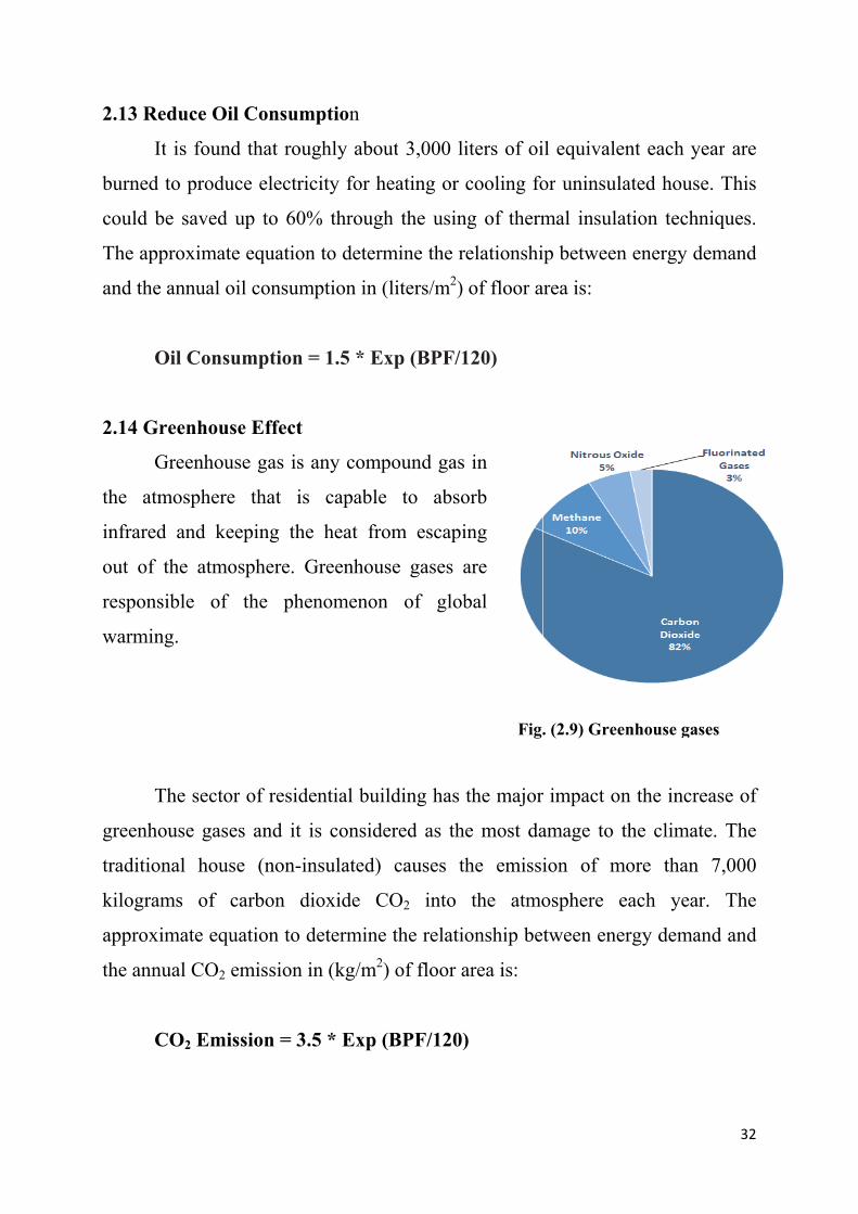
G
the at
infrare
out of
respon
warmin
T
greenh
traditio
kilogra
approx
the ann
Reduce Oi
It is found
d to produ
be saved
pproximate
e annual o
Oil Consu
Greenhous
Greenhou
tmosphere
ed and ke
f the atmo
nsible of
ng.
The secto
house gase
onal hous
ams of c
ximate equ
nual CO2 e
CO2 Emi
il Consum
d that rou
uce electric
up to 60%
e equation
oil consum
umption =
se Effect
use gas is
e that is
eeping the
osphere. G
the phe
r of reside
es and it i
se (non-in
carbon d
uation to d
emission i
ssion = 3.
mption
ughly abou
city for he
% through
n to determ
mption in (
= 1.5 * Ex
any comp
capable
e heat fro
Greenhous
enomenon
ential buil
is conside
nsulated)
ioxide C
determine
in (kg/m2)
.5 * Exp (
ut 3,000 li
eating or
h the usin
mine the r
(liters/m2)
xp (BPF/1
pound gas
to abso
om escapi
se gases a
n of glob
lding has
ered as th
causes th
CO2 into
the relatio
) of floor a
(BPF/120)
iters of oi
cooling fo
ng of therm
elationshi
of floor a
120)
in
orb
ing
are
bal
Fig.
the major
e most da
he emissi
the atmo
onship be
area is:
)
il equivale
or uninsul
mal insula
ip between
area is:
. (2.9) Gree
r impact o
amage to
ion of m
osphere e
tween ene
ent each y
lated hous
ation tech
n energy d
enhouse ga
n the incr
the clima
more than
each yea
ergy dema
32
year are
se. This
hniques.
demand
ses
rease of
ate. The
n 7,000
ar. The
and and

33
Example (3): Extra calculations for oil consumption and CO2 emission
A house of 10 m x 5 m x 3 m dimensions has insulated walls and ceiling, as
shown in the figure. Neglect the effect of radiation and convection heat transfer.
Add 4000 W due to the heat gained through other sources. Calculate:
1. Total heat transmitted through the building.
2. Annual electricity consumption in the
building as a result of cooling (Suppose the use
of air-conditioning for 120 days).
3. Efficiency of the building.
4. Oil consumption in power plant as a result of
the annual consumption.
5. CO2 emissions in power plant.
Kplaster=1, KEPS=0.05, Kthermostone=0.3, Kgypsum=0.8
Solution:
1) Heat transfer
Plaster R1 = x1/k1 = 0.02/1 = 0.02
EPS R2 = x2/k2 = 0.04/0.05 = 0.8
Thermostone R3 = x3/k3 = 0.24/0.3 = 0.8
Gypsum R4 = x4/k4 = 0.02/0.8 = 0.025
Total resistance R = R1 + R2 + R3 + R4 = 1.645
U = 1 / R = 0.608 W/m2.K
A = (10*3*2) + (5*3*2) + (10*5) = 140 m2 total area of walls and roof
Q = U A (Ti-To) = 0.608 * 140 * (48-25) = 1957 W
2) Annual Electricity Demand
Qtotal = 1957 + 4000 = 5957 W
AED = Qtotal * N / 100 = 5957 * 120 / 100 = 7148 kWh
3) BPF = AED / Floor Area = 7148 / 50 = 143 kWh/m2 medium energy house
4) Oil Consumption = 1.5 * Exp (BPF/120) = 1.5 * Exp (143/120) = 5 liters/m2
5) CO2 Emission = 3.5 * Exp (BPF/120) = 12 kg/m2

34
2.15 Thermal Images
Thermal images could be captured using thermal cameras like: FLIR,
FLUKE and MSA. A thermographic image is used to illustrate the difference
between the well and poorly insulation levels. Heat loss through the wall is
highlighted by several colors. The amount of radiation emitted increases with
temperature, therefore warm objects appears in red color against blue colors for
cool objects.
Example: Thermal images of a building have been captured in the winter, as
shown in the figure below. Explain your understanding.
a. Before insulation b. After insulation
Answer: In image (a), where there is no insulation, heat is transferred easily
through the walls and other building elements. Thus, the outer faces close to be
red and yellow. On the other hand, in image (b) after insulation, heat is
accumulated inside and the outer faces have the same ambient temperature, thus
appeared in blue and green.

35
2.16 Economical Effect
The quality of the insulation materials are chosen to satisfy the
requirements of good insulation and reduce energy consumption. To make the
process more economical, thermal insulation of the building must be chosen
carefully according to the following factors:
- The amount of insulation material and thickness.
- The cost of insulation material and labor costs, which will install it.
- The amount of energy that is saved to the building. Hence, the saved money.
The economical value of insulation equals to the cost of the insulators
minus the cost of air-conditioning units that is saved for a certain period. It has
found that super insulation of the building increases the cost of construction up
to 20%, but this amount would be recovered as a result of lower electricity bills
in a few years. Some countries encourage the low-energy homes by exempting
the electricity bills. The costs of some insulators are shown in the table below.
Table (2.8) Average costs of some common insulators
Item Insulation Material Cost ($/m2) for each cm thickness 1 Alucobond 202 Asbestos 83 Asphalt 24 Cellulose 1.55 Cement 66 Clay 0.77 Coal 28 Cotton 39 Cork (EPS) 1.5
10 Glass Fiber 2.511 Glass Wool 2.512 Gypsum Plaster 313 Perlite 414 Polystyrene 315 Polyurethane 616 Rubber 217 Wood 1518 Wool 819 Granite 1820 GRC 1021 Limestone 1222 Sandstone 1223 Marble 1824 Basalt 12

36
2.17 Useful Applications
There are some tools used to obtain the contribution of thermal insulation
to energy saving, fuel consumption and CO2 emissions. The course included 2
computer-lab hours for the certain applications:
Iraqi Passive House Planning Package (IPPP): It is a visual basic based
design tool that is used to find complete energy balance of passive or active
buildings in Iraq. The application is very responsible for the hot climate zone of
Iraq. It includes the following features:
- Meteorological data (18 cities in Iraq) - Properties library for different construction materials and insulations - Cooling and heating load calculation for residential building - Electricity power consumption - Contribution of renewable energy - Indoor air quality and ventilation system - Passive house standards verification - Oil consumption - CO2 emission - Cost analysis
Fig. (2.10) Main form of Iraqi Passive House Planning Package

37
RETScreen: is a clean energy management software system for energy
efficiency, renewable energy and cogeneration project feasibility analysis as
well as ongoing energy performance analysis. RETScreen 4 is an Excel-based
clean energy project analysis software tool that helps to determine the technical
and financial viability of potential clean energy projects. The application
includes the following features:
Fig. (2.11) Main form of RETScreen
More information are available on the site: http://www.retscreen.net/

38
Chapter Three
Acoustic Insulation

39
Chapter Three
Acoustic Insulation
3.1 Acoustic Insulation
Acoustic insulators are those materials that prevent sound transmission or
absorb it. Sound is transmitted in form of pressure waves through the air where
we can distinguish various voices as well as the noise. Sound travels also
through solid objects. The continuous sounds surrounding mankind may lead to
nervous tension and affect the behavior and action of people. Therefore,
environmental engineering identified appropriate sound levels for living and
working. Since, it is easy of sound transmission through concrete parts, thus, it
should always control the design of the building and select the most appropriate
soundproofing materials. The insulation of building prevents the transmission of
sound outside or inside and from room to another.
3.2 Architectural Procedures to Control the Acoustics
1. Planning methods of determining the home position relative to sources of
external sounds such as streets, markets and factories as well as the correct
orientation of windows, doors, etc.
2. Design methods for internal spaces of the building.
3. Methods of choosing perfect soundproofing material.
3.3 Objective of Acoustic Insulation
1. Prevent transmission of sound from the outside.
2. Prevent transmission of sound between the rooms through walls and ceilings.
3. Prevent the transmission of sounds and vibrations of machines.
4. Absorption of sound inside.

40
3.4 Procedures of Acoustic Insulation
1. Walls: Using wall tiles and insulating materials such as cork, glass wool and
polyurethane foam.
2. Roof: using insulators such as plastic sheets, secondary or ceiling panels,
perlite and vermiculite.
3. Dampers: some rubbers, fiberglass or certain panels could be placed under
vibrating machines or inside the room. The pieces of furniture help to absorb
amount of sounds.
4. Avoid acoustic bridge: it is a term describes the region that allows the
transmission of sound a result of the damage in insulator or in case of absence it
basically. One of these areas is the joint link between the walls and the ceiling or
between the walls and floor slabs.
3.5 Classification of Acoustic Insulators
The incident sound upon a surface could be distributed into three main
parts. The first part is reflected from the surface, the second part is absorbed by
the surface while the last part is transmitted across the surface to inside. So it
could say that the sound-proofing materials are divided into:
1. Reflective materials
2. Absorbing material
Fig. (3.1) Distribution of sound

41
3.6 Commercial Insulators
1. Acoustic tiles, these tiles have the capability of sound absorption, durability
and ease of cleaning. Often, they are made of composite materials such as quartz
mixed with granular resin, as well as the fiberglass, that results from the mixing
of glass wool with epoxy. These tiles are used for the absorption of sounds of
machines.
2. Glass wool or rock wool, they are characterized by the ability to absorb sound
and thermal insulation, and can be mounted on the walls and ceiling. These
could be used in commercial and industrial buildings.
3. Polyurethane foam which are available in the form of spray, layers and tiles.
4. Cellulose panels which are compressed and perforated face.
5. Gypsum boards with the addition of fibers to the surface.
6. Rubber in many forms natural rubber panels, industrial chloroprene (neoprene
or polychloroprene) and layers of Mass Loaded Vinyl (MLV). These are
available in panels and rolls and they have high sound absorption and they are
used to cover the walls, as well as to absorb vibrations.
7. Natural cork or synthetic cork (EPS).
8. Plastic packaging sheets: these layers fit for ceilings in factories where large
dimensions. These are resistant to dust as well as the moisture.
9. Perlite, a white color substance taken from the volcanic rocks, and it is a good
insulator of sound and heat. It gives the surface a reliable fire-resistant. Perlite is
used to insulate the ceiling, walls and floors.
10. Viscoelastic damping compound (VDC), a viscous resin fast to dry, used in
flooring damping, absorption of the noise as well as to absorb the vibrations of
machinery and ducts.
11. Fabrics, leather, carpet and sponge materials.
12. Metallic panel, it is similar in work to the silencer where it dissipates the
undesired sounds and then absorbs it by acoustic insulation inside (fiberglass).

42
Polyurethane, 5 cm, 32 kg/m3, NRC=0.9 Rock wool, 5 cm, 60 kg/m3, NRC=0.7
Acoustic tiles (Quartz, 1250 kg/m3) Metallic panel
Fiberglass (48 kg/m3) Mass Loaded Vinyl (16 kg/m3)
Fig. (3.2) Sound insulators

43
3.7 Acoustical Engineering
Sound: it is a kind of mechanical energy. Sound travels from one place to
another in the form of pressure waves occurring vibrations in the air or building
materials. And it can distinguish between sounds by ear or audio devices. The
sound does not move in a vacuum but only in a medium. The science of
acoustics describes the source of the sound, its transmission and sensing of it.
There are some basic definitions in acoustics science, including:
Type of sound: it is the property that distinguishes between different types of
sounds. For example, the voice of a man, an animal, a machine, etc.
Quality of sound: it is the property that characterized the pitch change to the
same source. it depends on the frequency of sound waves which characterized
the loudness of sounds, such as the difference between the sound of men and
women and the difference between mature and young voices, as well as sound in
joy and sorrow.
Sound intensity: it is the property that differentiates between sounds in terms of
being high or low.
Sound frequency: it is the number of times that air particles fluctuate per
second as a result of sound energy passed. It is expressed in the unit of Hertz
(Hz). Most of the sounds that we hear are a mixture of frequencies.
Classification of sound waves
1. Infrasonic: waves that have less than 20 Hz frequency.
2. Sonic: waves that have frequencies between 20 Hz and 20,000 Hz.
3. Ultrasonic: waves that have frequencies above 20,000 Hz.

44
Sound power: it is the energy carried by the acoustic wave in a period of time.
And it is measured in watts.
Sound intensity: mathematically, it is the amount of acoustic energy on a unit
area. Human ear can feel a sound has 10-12 W/m2 intensity as minimum. The
highest intensity of sound within earshot is 1 W/m2.
Iref = 10-12 W/m2
Sound Intensity Level (SIL): The sound intensity value is too small and it is
difficult to compare with, so it is looking for a value more acceptable like
(Decibel) which is symbolized by (dB). The lowest sound level value is zero dB.
The sound level could be accounted from the relation:
SIL = 10 log (I/Iref)
Based on that, the sound is classified in terms of the level of intensity to:
0 - 40 dB : Quiet
40 - 80 dB : Noisy
80 - 120 dB : Very noisy
> 120 db : Intolerable
Sound pressure: It is the change of atmospheric pressure in a region as a result
of the passage of sound. The less sound pressure feeling by human ear is about
2x10⁻⁵ Pa and this is called the hearing threshold. At a pressure of about 20 Pa
the ear starts feeling of pain.
Pref = 2x10⁻⁵ Pa
Sound Pressure Level (SPL): it is a value similar to the sound intensity level,
and also measured in decibels. It is calculated from the relation:
SPL = 20 log (P/Pref)

45
Table (3.1) Properties of some sound sources.
3.8 Sound Transmission
It means the ability of sound to move across the building from one part to
another. There are several ways for sound moving which are:
- Airborne transmission: it referred to the sound transmitted through windows
and openings. These can be processed by good sealing.
- Impact transmission: It means the voices of people movement as well as of the
machines on the upper floor. These can be treated by absorbing layers and
dampers such as carpet and rubber.
- Flanking transmission: It means the sound transmission through the parts of the
building (concrete, metal, wood or glass). These are processed using insulating
materials. Any part of the building has a number represents the amount of
resistance to the permeability of sound which is called (Transmission Loss).

46
Transmission loss
It is a measure of the sound difference in decibels through the barrier. For
example, if we have a sound of 100 decibels on a side of the wall. Then we
measured this sound on the other side and we found it is 55 dB. Then we say
that the wall has 45 dB transmission loss. The higher value indicates good
resistance and good acoustic insulation. This value varies depending on the
frequency of the sound source.
Fig. (3.3) Transmission loss
Sound Transmission Class (STC)
It is the amount of transmission loss through a barrier or a wall at a sound
frequency of 500 Hz. Sound transmission class is a key factor in the design and
represents an indication of the building element performance to resistance the
sound transmission through it.

47
Table (3.2) STC values of some building elements
Partition type STC
Single glass window 27
Double glass window 30
Single layer of 1 cm drywall on each side, wood studs, no insulation (typical interior wall) 33
Single layer of 1 cm drywall on each side, wood studs, fiberglass insulation 39
10 cm hollow CMU (Concrete Masonry Unit) 44
20 cm thermostone wall with plastering for both sides 44
Double layer of 1 cm drywall on each side, wood studs, batt insulation in wall 45
Single layer of 1 cm drywall, glued to 15 cm lightweight concrete block wall, painted both sides 46
15 cm Hollow CMU (Concrete Masonry Unit) 46
20 cm hollow CMU (Concrete Masonry Unit) 48
25 cm hollow CMU (Concrete Masonry Unit) 50
20 cm hollow CMU (Concrete Masonry Unit) with 5 cm Z‐Bars and 1 cm drywall on each side 52
20 cm concrete floor with plastering for both sides 53
Single layer of 1 cm drywall, glued to 20 cm dense concrete block wall, painted both sides 54
20 cm hollow CMU with 5 cm wood Furring, 5 cm fiberglass insula on and 1 cm drywall on each side 54
24 cm brick wall with plastering for both sides 54
Double layer of 1 cm drywall on each side, on staggered wood stud wall, batt insulation in wall 55
Double layer of 1 cm drywall on each side, on wood stud wall, batt insulation 59
Double layer of 1 cm drywall on each side, on wood/metal stud walls (1 cm space), double batt insulation 63
20 cm Hollow CMU with 8 cm Steel Studs, fiberglass Insula on and 1 cm drywall on each side 64
20 cm concrete block wall with 1 cm drywall on steel stud walls, each side, insulation in cavities 72

48
3.9 Sound Absorption
Any substance has the ability to absorb sound in addition to its ability to
reflect the sound. The energy absorbed is converted into heat. Sound absorption
factor is a value describes the ability of sound absorption. The absorbance in
porous materials is more than in dense solids.
Coefficient of sound absorption: It is the ratio between the energy absorbed by
the surface to the total energy incident up on the surface. The parameter is
denoted by the symbol (α).
Table (3.3) Coefficients of sound absorption at differente frequences
Note:
It can be seen from the table above that the absorption coefficient of the
material varies with the source frequency. In some cases, taking the average of
these values is preferred and this is what so-called Noise Reduction Coefficient
(NRC) which is commonly used to describe the value of the absorbance of the
insulating material.

49
Table (3.4) Noise reduction coefficient of some insulating materials
Material NRC
Acoustic tiles 0.8‐0.9
Polyurethane 0.8‐0.9
Mass vinyl 0.75
Glass wool 0.7
Asbestos 0.6
Mineral wool 0.65
EPS, XPS 0.3‐0.4
Rubber 0.2
Absorption capacity: it represents the amount of acoustic units that can be
absorbed by the barrier or the wall. Sound absorption unit is called (Sabin). The
absorption capacity depends on the space area and absorption coefficient
according to the relationship:
C = α x A
3.10 Noise Reduction (Attenuation)
The total amount of reduction in the acoustic energy as a result of
reflection and absorption when moving from a room to another or abroad is
called the noise reduction. This amount is expressed in the relationship:
NR = TL + 10 Log (C/A)
Where: TL is the loss transmission of the walls
C is the absorption capacity of the room
A is the area of the separation wall
Note: in the design usually suppose a sound frequency value of 500 Hz which is
still within the range of the voices of people and cars, as shown in the figure
below.

50
Fig. (3.4) Relation between sound level and frequency
So it could say that:
TL = STC
In case of high ranges of frequencies, then it is acceptable to use the
correction chart as shown in the figure below.
Fig (3.5) Correction of STC value at many sound frequencies

51
3.11 Engineering Calculations
Here are some examples to show the effect of acoustic insulators.
Ex. (1) A conference hall of 10 m x 6 m x 3.5 m, has 3 walls of gypsum
(α=0.05), one facade of glass (α=0.03), ceiling of plastic tiles (α=0.1) and floor
of carpet (α=0.3). An office is located next door to the hall, as shown in the
figure.
Find:
a) Total absorption for the conference hall. (Absorption of furniture=20 Sabins)
b) Noise reduction for the office room. (STC of the separated wall is 48)
c) Total absorption for the conference hall if the separated wall is covered by
acoustic tiles (NRC=0.9)
d) Noise reduction for the office room after insulation. (STC of the separated
wall becomes 54)

52
Solution
a)
- Walls (gypsum) A = 10*3.5+6*3.5*2 = 77 m2
C = α x A = 0.05*77 = 4 Sabins
- Wall (glass) A = 10*3.5 = 35 m2
C = α x A = 0.03*35 = 1 Sabin
- Ceiling (plastic tiles) A = 10*6 = 60 m2
C = α x A = 0.1*60 = 6 Sabins
- Floor (carpet) A = 10*6 = 60 m2
C = α x A = 0.3*60 = 18 Sabins
Ctotal = Cwalls + Cceiling + Cfloor + Cfurniture =4+1+6+18+20 = 49 Sabins
b) NR = TL + 10 Log (C/A) = 48 + 10 Log (49/21) = 52 dB
c) Acoustic tiles A = 6*3.5 = 21 m2
C = NRC x A = 0.9*21 = 19 Sabins
Ctotal = 49+19 = 68 Sabins
d) NR = TL + 10 Log (C/A) = 54 + 10 Log (68/21) = 60 dB
It is an excellent insulation.

53
Ex. (2) A living room of 6 m x 5 m x 3 m has the following features:
Element Material α
Walls Plywood 0.2
Ceiling Gypsum 0.05
Floor Carpet 0.3
What would be the noise attenuation with respect to the upper bed room for:
1- Before insulation.
2- After insulating the ceiling by 5 cm glasswool (NRC=0.7).
Take into account that STC of the roof without insulation is (48) and with insulation is (54). There is an additional absorption due to the furniture (15 Sabins).
Solution
1-Befor insulation
- Walls (plywood) A = 6*3*2+5*3*2 = 66 m2
C = α x A = 0.2*66 = 14 Sabins
- Ceiling (gypsum) A = 6*5 = 30 m2
C = α x A = 0.05*30 = 2 Sabins
- Floor (carpet) A = 6*5 = 30 m2
C = α x A = 0.3*30 = 9 Sabins
Ctotal = Cwalls + Cceiling + Cfloor + Cfurniture =14+2+9+15 = 40 Sabins
NR = TL + 10 Log (C/A) = 48 + 10 Log (40/30) = 50 dB
2-After insulation
- Glasswool A = 6*5 = 30 m2
C = NRC x A = 0.7*30 = 21 Sabins
Ctotal = 40+21 = 61 Sabins
NR = TL + 10 Log (C/A) = 54 + 10 Log (61/30) = 57 dB Very good insulation.
Bed Room
Living Room

54
Ex. (3) A generator is located outdoor a warehouse (10 m away), and beside the
external wooden door, as shown in the figure below. Measuring of sound level
during the running of the generator gives (90 dB). Neglect the sound
transmission across the walls.
1. Find the noise reduction across the door to the inside without insulation.
Absorption of sound by the atmosphere is (0.5 dB/m).
2. What would be the thickness of the insulator in order to achieve (35 dB)
inside.
Solution: 1) Before insulation
Absorption by the atmosphere = 0.5 x 10 = 5 dB
From the table choose STC = 20
NR = TL + Absorption = 20 + 5 = 25 dB
2) After insulation
NR = 90 – 35 = 55 dB
TL = NR – Absorption = 55 – 5 = 50 dB
From the table choose Type (D), so the thickness of insulator is (15 mm).
Type Description STC
A Door without insulator 20
B Door with 5 mm insulator 30
C Door with 10 mm insulator 40
D Door with 15 mm insulator 50
E Door with 20 mm insulator 60

55
3.12 Noise Pollution in Industrial
The steady increase in the noise level result in a permanent damage in the
auditory system, as well as some attendant symptoms like: reducing the heart
rate, changing in blood pressure and difficulty of breathing. As the
psychological impact on the individual worker, protrudes through the change the
style of his sleep, thus accompanying fatigue in the body which will affect the
production efficiency of the working. If the worker is exposed to a continuous
noise (80 dB) during the period of his work, then that will lead to loss 15 dB
approximately in his hearing threshold during several years (i.e., he loses the
level of whisper).
The sound level is measured using a device called sound level meter, as
shown in the figure below.
Fig (3.6) Sound level meter
The prevention of noise pollution satisfying the industrial safety
conditions required in the lab, factory and warehouse. So, it must follow these
steps:
1. Use suitable damper for high-vibration machines.
2. Use soundproofing for the purpose of absorption and dispersion of sounds.
3. Use of ear protectors as a prerequisite for workers.

56
Vibration pad (Neoprene or vinyl) Viscoelastic compound
Noise Control Baffles (fiberglass) Curtain
Fig. (3.7) Noise dampers

57
Example: Noise control baffles of fiberglass are used to reduce the overall noise
level in an industrial plant (80' L x 40' W x 20' H), and they are suspended above
the noise source, as shown in the figure below. The walls and ceiling are
concrete, while the floor is carpet. Estimate the number of baffles for noise
reduction of 8 dB. Use the nomogram.
Hard surface like: concrete, brick, marble
and gypsum. Absorptive surface like:
wood and carpet.
Nomogram
Term Description
Hard 6 hard surfaces
Med. Hard 5 hard surfaces and 1 absorptive
Medium 4 hard surfaces and 2 absorptive
Med. Soft 3 hard surfaces and 3 absorptive
Soft 2 hard surfaces only or even one

58
Solution: 1. Determine the total surface area:
2. Connect (area=11200) and (medium hard) on the nomogram. Extend the line to reference line and point the intersection. 3. Connect a line between the intersection point and (8 dB) on the reduction line. 4. The number of baffles required is 200.
80' x 20' x 2' (walls) = 3200
40' x 20' x 2' (walls) = 1600
80' x 40' x 1' (ceiling) = 3200
80' x 40' x 1' (floor) = 3200
Total Area = 11200 sq. ft.

59
Chapter Four
Waterproofing Insulation

60
Chapter Four
Waterproofing Insulation
4.1 Waterproofing
All buildings need insulation from moisture, rain, groundwater and
surface water because the dampness causes in damage of the construction
materials and releases undesired smells with the breeding of insects and mice
and bring diseases. The walls that exposed to the rain without sufficient amount
of sunlight are more susceptible to dampness.
4.2 Effect of Dampness
- Damage of building materials and elements of the house.
- Efflorescence of the walls, floor and ceiling.
- Damaging the paint.
- The failure in the timber used and wooden décor.
- Corrosion of metallic parts.
- Proliferation of fungi and unhealthy situation for users in the building.
4.3 Causes of Dampness
1. Rain water: The rain water has the ability to penetrate the roof of the
building, especially for poor surfaces and absence of gutters. Rain could
penetrate the windows in absence of overhangs.
2. Surface water: This means river, sea or pond. The water mixes with the soil
close to the building and forming a clay then moisture seeps to the foundations
or inside through the capillary action.
61
3. Underground water: The accumulated water under the earth's surface could
be transmitted through the pores of the soil by the capillary action and ascend to
the foundations or inside hence damage the structural materials used in the
building. It could even overflowing into the building.
4. Condensation: It is noticed in winter days a layer of dew formed on the
window or even wall, and this phenomenon is called "condensation". The
accumulated moisture on windows, walls, ceiling and floor seeps into the parts
of the house after a period of time and leads to the fragility of construction
materials and the appearance of rust, mildew and odors.
5. Poor sewage drainage: When wastewater gathers under the building and it
was hard to flow downstream because of some restrictions then dampness could
be occurred in the nearby elements of the building.
6. Modern construction: The walls newly constructed remain in the wet state
for a certain period.
Capillary action: It is the ability of water to transport through the small pores
of the material with the help of the forces of adhesion and cohesion. The
capillary action occurs in porous materials like sponge, brick, concrete and
many construction materials.
4.4 Types of Waterproofing Insulators
The purpose of waterproofing materials is to prevent the water as well as
the moisture and keep it away from building elements. In order to choose the
appropriate isolator of humidity it must take into account the nature of the
ground (concrete, stone, clay, metal) as well as the climate (dry, wet). The
method is characterized by the development of the insulation layer or membrane
resists water pressure and using materials to prevent leakage of water or
moisture into building elements.

62
The main types of waterproofing materials are:
Bitumen: It is a black material made from the rest of the distillation of crude oil.
Bitumen is very common in waterproofing isolation because of its cheapness
compared to the other insulating materials in addition to its flexibility and
resistance to the proliferation of fungi and insects. Bitumen is available in drums
where it should be heated to about 80 degrees to melt. The most famous types
are:
- Liquid of bitumen which is used to fill the cracks in the concrete or roof tiles.
Sometime, adhesive is added to the resin components and it is called "mastic".
Bitumen could be used as paint (1-2 mm) for the foundations and walls that are
in a direct contact with the soil.
- Solid of bitumen (asphalt) which is used for paving of the street after mixing
with sand and stones.
- Flancoat: a waterproofing material of bitumen used for coating surfaces of
concrete in contact with the soil to prevent the dampness. It is effective and easy
to use and does not need any mixing with any compound. It does not need to
melt, where a brush or a roll is used to paint the surfaces. Often, it is available in
black, but there are many other colors.
- Bitumen rolls: These layers have the excellent isolating and waterproofing
capability. They are made of bitumen and sometimes covered by a reflective
metallic sheet to reflect the heat. The bitumen layer commonly used to insulate
the ceiling or walls and it is available in (3, 4 and 5 mm) thickness.

63
Acrylic: It is a water resistant material and frequently used for waterproofing of
the building roof and the floor of swimming pool. This material is composed of
polyester fibers submerged in a liquid resin of polyacrylonitrile, where the
required surface should be painted (many layers) and exposed to air to dry
quickly and becomes a flexible insulating layer. This substance has a high
susceptibility adhesion to various building materials. It is long-life and
environment-friendly material.
Waterproofing liquid: This liquid is made from the mixing of paraffin's wax
with volatile oil. The waterproofing liquid is used to spray or paint the required
surfaces.
Epoxy: A polymeric material sticky and has rapid solidification used to process
the holes and cracks.
Cement: In case of free of impurities, cement could be a good resistant
insulator. Cement is available as:
- Portland cement: the increasing of the amount of cement in cement-sand
mixture increases the resistance.
- White cement: it is used to fill the separations in marble tiles for bathrooms
and balconies.
Fiberglass: It is a hard kind that results from mixing the glasswool with the
epoxy. It is characterized by high resistance to the water therefore used in tank
construction. Glasswool could be also mixed for the purposes of strengthening
bitumen waterproofing layer.

64
Sheets or layers: Surfaces could by isolated using many layers like:
- Polyethylene membrane: Polyethylene is a flexible material that resists
moisture and is often found in a very thin layer.
- Rubber sheets
- Extruded polystyrene (XPS) layers.
- Layers of Mass Loaded Vinyl (MLV).
- Nylon: It can be used between different parts of the building or between the
layers of insulators, as well as to cover the foundations.
- Metallic sheets: slabs, roofs and walls could be covered by a tiny layer of
metallic sheet such as copper and aluminum plates. These metals are commonly
used to make water storages.
Shingle: These tiles have good isolation and used to cover the inclined surfaces
and remove the accumulated water. A shingle is made of durable material like
brick, stone or composite material and has a beautiful appearance.
Asbestos: It is ceiling panels characterized by light weight and resistance to
water, heat, fire, acids and fungi. The asbestos panel is often used in roofing but
it is prohibited recently due to its harmful effect to the body health and
environment.
Rocks: Such as marble and granite. They are characterized by hard surfaces so a
high resistance to the water. Marble is commonly used as floor tiles in kitchens
and bathrooms. These rocks could be used to make the statues.

65
Asphalt Bitumen paint Shingles
Acrylic
Bitumen rolls Polyethylene membrane
Fig. (4.1) Waterproofing materials

66
4.5 Practical Waterproofing Treatments
A. Waterproofing of foundation
1. Paint foundation surface using bitumen paints to prevent water transport and
to provide adhesion between the concrete and insulation layer.
2. Paste a layer of tarpaulin to protect the foundation from direct contact with
water.
3. Put a layer of thermal insulator.
4. Fill the neighboring land to the foundation by stones to resist the permeability
of the water as much as possible (see the figure below).
B. Waterproofing of walls
1. Paint wall surface using bitumen paints to prevent water transport and to
provide adhesion between the wall and insulation layer.
2. Paste a layer of tarpaulin, to protect the walls from direct contact with water,
starting from the underground to prevent dampness path to the top.
3. Put a layer of thermal insulator.
4. Finishing works by a layer of mortar or marble.
C. Waterproofing of roof
1. After the casting of concrete, surface should be cleaned and the cracks should
be treated carefully using grout or epoxy.
2. Provide appropriate inclination towards the gutters and treating the
cumulative area by a layer of cement.
3. Paint concrete surfaces using bitumen paints to provide adhesion between the
concrete and the insulation layer.
4. Put a layer of waterproofing material.
5. Put a layer of thermal insulating material.
6. Put a layer of soil and then covering with impervious tiles or insulating
membrane such as acrylic.

67
Fig. (4.2) Waterproofing of foundation
4.6 Engineering Calculation in Water Transport
Permeability: It is a measure of the ability of a porous material to allow liquids
to pass through it; hence it is the inversion of the resistance. The unit of
permeability is Darcy (D).
1 Darcy ≈ 10−12 m2
Velocity of the liquid in a permeable material is given by:
Where:
υ = flow velocity through the medium (m/s)
k = coefficient of permeability of the medium (m2)
μ = dynamic viscosity of the fluid (Pa·s)
∆P =Applied pressure difference (Pa)
∆x = thickness of the bed of the porous medium (m)

68
The table below shows values of water permeability for some materials.
Table (4.1) Values of water permeability for some materials
Unconsolidated
Sand & Gravel
Well
Sorted
Gravel
Well Sorted Sand
or Sand & Gravel
Very Fine Sand, Silt,
Loess, Loam
Unconsolidated
Clay & Organic Peat Layered Clay Unweathered Clay
Consolidated
Rocks
Highly Fractured
Rocks Oil Reservoir Rocks
Fresh
Sandstone
Fresh
Limestone,
Concrete
Fresh Granite
κ (milliDarcy) 108 107 106 105 10000 1000 100 10 1 0.1 0.01 0.001 0.0001
Strength Pervious Semi-Pervious Impervious
Example: A swimming pool of 60 m2 has a concrete floor of 10 cm thickness
and exposed to 20 kPa pressure difference of water. Determine the discharge of
water across the concrete. (μ of water = 0.001 Pa.s) (k of concrete = 0.01
miliDarcy). What will be the difference if granite is used (k of granite = 0.001
miliDarcy).
Solution
In case of concrete
= (0.01 x 10-3 x 10-12/0.001) (20000/0.1) = 0.2 x 10⁻⁸ m/s
Q = υ x A = 0.2 x 10-8 x 60 = 12 x 10-8 m3/s
In case of granite
υ = (0.001 x 10-3 x 10-12/0.001) (20000/0.1) = 0.02 x 10⁻⁸ m/s
Q = υ x A = 0.02 x 10-8 x 60 = 1.2 x 10⁻⁸ m3/s

69
Sorption: It is the tendency of water to rise into porous materials by capillary
action. Thus, no water pressure is required. The quantity of water absorbed into
the material by capillary action is given by:
√
Where
V = accumulated volume by absorption (m3)
A = wetted area (m2)
S = Sorptivity of the material ( /√ )
t= time (min)
Table (4.2) Values of water sorptivity for some materials
Material S ( /√ ) Stone 0.15
Concrete 0.2
Block 0.5
Brick 1.1
Cement 1.5
Gypsum 3.5
Soil 40
Example: Brick wall (S=1.1 /√ ) of 5 m width, 3 m high and 25 cm
thickness is attached to underground water. What would be the dampness level
for a period of one month, if the water touches 10 cm of the foundation height.
What is the difference if impervious brick (S=0.1 /√ ) has been used.
Solution:
√ = (5 x0.1) x 1.1 x 10-3 x √30 24 60 = 0.114 m3
Water rise = V / A = 0.114 / (5x0.25) = 0.091 m
It means that the water will rise approximately 9 cm after a month.
For the case of impervious brick it is less than 1 cm monthly. Check it!!

70
Chapter Five
Radiation Insulation

71
Chapter Five
Radiation Insulation
5.1 Introduction
It is known that various electromagnetic waves and particles emitted from
radioactive sources have direct and indirect effects on living organisms, where
many symptoms could be happened when expose to radiation more than
allowed. Workers in nuclear facilities and X-ray labs exposed to the risk of
external, which affects the face, hands or internal exposure due to the entry of
radioactive particles into the body through breathing and food. To avoid the
radiation risk in this area it is necessary to know the nature of radiation and
methods of isolating and comply with the instructions for the prevention of it as
mentioned in this chapter.
5.2 Radiation
Radiation is energy released in the form of electromagnetic waves has
many forms, such as light, ultraviolet and infrared or small particles from
radioactive materials like alpha, beta and gamma. The source of this radiation is
universe, sun, nuclear reactors, industrial and laboratory applications. Some
substances found in the earth are also characterized by radiation. There is a little
radioactivity within the body. Electromagnetic waves consist of photons;
shortest waves are gamma rays while the longest are radio waves.

5.3 Cla
R
1. No
ultravi
2. Ioni
beta pa
assificatio
Radiation
on-Ionizin
olet and ra
izing Rad
articles. It
F
on of Rad
n could be
ng Radia
adio wave
diation: S
is danger
Fig. (5.1) E
diation
classified
ation: Ex
es. This ty
Such as co
rous becau
Electromag
d according
xamples
ype of radi
osmic ray
use of its a
netic wave
g to its dan
of this r
ation is sa
ys, gamma
ability of i
s
nger as fo
radiation
afe usually
a rays, alp
onizing.
ollowing:
light, in
y.
pha particl
72
nfrared,
les and

73
5.4 Non-Ionizing Radiation
The sources of these rays are sun or industrial applications. These rays are
not inherently dangerous, but when prolonged exposure to it has caused cases of
discomfort or headaches queasiness or dryness of hair and sometimes minor skin
burns. Clothes, sunglasses and shading protect us from these rays.
5.5 Types of Non-Ionizing Radiation
1. Light (the visible spectrum): It is a very useful radiation. It provides the
light and control many biological functions such as: strengthen of bone tissue,
maintain the blood pressure, diabetes level, cholesterol level and psychological
comfortable. It has a big role in the growth of plants by photosynthesis.
2. Infrared: It is very useful where provides the warmth and used for many
applications like: night vision, short-range wireless communications and remote
sensing.
3. Ultraviolet: It is a useful radiation except one band of it. These rays help to
provide the body with vitamin (D). There are many application of UV like:
water and medical sterilization, reducing the yellowing with newborns. The long
exposure to UV harms the skin and the eye. It is worth to refer that that these
rays are the cause of damaging plastics and insulating polymeric materials
because of their ability to destroy the chemical bonds.
4. Radio waves: Such as the broadcasting of radio, television,
telecommunications and microwave wavelengths. Despite the benefits of these
rays in the transfer of information, they have some harmful effects on humans,
especially on the nervous side and the senses.

74
5.6 Ionizing Radiation
It includes rays or particles come from the sun, the universe or radioactive
elements (such as radium, uranium, plutonium, thorium, iodine, potassium,
zircon, phosphor and radon). The radiation that is emitted from these sources
could ionize the medium, which means detaching the electrons from atoms.
5.7 Radioactivity
Most of the chemical elements have the same number of neutrons and
protons in the nucleus. in some elements the number of neutrons is greater than
the number of protons, so that be unstable and called radioactive isotopes. these
isotopes emit small particles from the nuclei such as alpha particles, beta
particles and gamma rays. Over time, these elements are transformed into other
elements less weight and have various chemical and physical characteristics.
The emitted particles and rays are considered as ionizing radiation. The
characteristics of radioactive isotopes depend on the type of radiation emitted,
energy of radiation and its half-life.
Half-Life: It is the time needed to disintegrate half of atoms of a radioactive
element, hence reducing the activity by half. For example, the half-life of
(iodine -131) is 8 days while the half-life of (radium -226) is 1600 years.
Fig. (5.2) The disintegration of the radioactive isotope

75
5.8 Types of Ionizing Radiation
1. Alpha particles: alpha particle is emitted from the nucleus during the decay.
It consists of two protons and two neutrons (i.e. similar to the nucleus of the
helium atom) so alpha has positive electrical charge. These particles lose energy
quickly as soon as leaving the radioactive element. Hence, the penetration of
alpha particles to the skin is weak, and it could be blocked by a thick paper. The
risk of alpha particles appeared when enter to the internal parts of the body by
breathing, eating or wounding.
2. Beta particles: These particles are emitted from the nucleus during the decay.
It is noticing, during the breakdown of neutrons, that beta particles may be
produced either as electrons (negative charge) or as positrons (positive charge),
or in sometimes whole neutrons are emitted to the outside. Beta has more
penetration force than alpha, and some beta particles can penetrate the skin and
damage it. It also causes harmful effects if entered to the body. Beta radiation
could be blocked by a piece of wood or a layer of aluminum (10-20 mm).
3. Gamma rays: This type of radiation represents the energy generated by the
disintegration that is occurred within the nucleus. The emission of alpha and
beta particles pushes the nucleus to the stability phase, hence emits energy
(photons) out in the form of gamma rays. There is a kind of gamma rays called
annihilation radiation which is produced from the combination of electrons and
positrons. this radiation is one of the most dangerous types of radiation and has
very high penetrating force, where it can easily penetrates the human body and
absorbed by the tissues. It could be blocked by a barrier of concrete or a layer of
lead (4-12 mm).

76
Fig. (5.3) Shielding for some types of radiation
4. X-rays: These rays are similar to gamma rays in terms of features but differ
in the source, where X-rays emitted from the outside of nucleus (transportation
of electrons between the energy levels), while gamma rays are emitted from the
inside of nucleus. Penetration force and permeability of these rays are less than
that of gamma rays, where it could be blocked by a thin layer of lead (1-3 mm).
5. Cosmic rays: These are high-energy particles coming from the space. Mostly,
this radiation is dissipated through the upper layers of the atmosphere, but a few
percent in. This dangerous radiation could be blocked by a layer of composite
materials or chemical compounds.
5.9 Risks of Ionizing Radiation
The ionizing radiation could ionize the medium, which means detaching
the electrons from atoms. The Ionizing of the constituent elements of the
biological material of the recipient's body causes the increase or decrease in the
size of the cell or fragmentation, hence the formation of toxic compounds that
may move to other parts of the body, leading to serious damage. These effects
are appeared either early or later in the form of symptoms or disease like

cancer
Worke
exposu
or ent
materia
radiatio
of radi
infertil
5.10 R
R
and co
measur
which
rous disea
ers in radi
ure to ioni
try into t
als attache
on dose to
iation are:
lity and ca
Radiation
Radiation
onsists of
red using
often wor
ases in ad
iation faci
zing radia
the blood
ed to the s
o the body
skin redn
ancer in so
Fig. (5
Measurin
n intensity
100 Rem
an instru
rks within
dition to
ilities may
ation occur
dstream. E
skin. The
y accordin
ness, burn
ome cases
.4) Warnin
ng
is measu
m. Human
ument call
the limits
Fig. (5.5
the hered
y get inte
rs when in
External e
type of da
ng to the l
ns, hair los
.
ng sign for i
ured in a u
n may exp
led radiat
s (0.1 - 200
5) Radiatio
ditary effe
ernal or e
nhaling or
exposure
amage is
level of ex
ss, syndro
ionizing ra
unit called
pose to a
tion meter
0 μSv/h).
on meter
ects of ge
xternal ex
r swallowi
occurs w
inflicted b
xposing. U
ome of rad
adiation
d Sievert,
dose of
r, as show
netic influ
xposure. I
ing radion
when radi
by the am
Usually th
diation, bl
denoted
radiation
wn in the
77
uences.
Internal
nuclides
oactive
ount of
he risks
eeding,
as (Sv)
that is
figure,

78
5.11 Means to Minimize the Risk of Radiation
Person who is working in the field of radiation may expose to a dose of
radiation depending on the nature of the work. The commitment to the following
aspects is very important to reduce the risk of radiation.
1) Time of Exposing
Radiation is less dangerous in the case of reducing the exposure time
(time spent by the person beside the radiation source). The maximum exposure
limit allowed to the human is (0.05 Sv/yr) according to the recommendations of
international councils such as (ICRP) and (USNRC). In order to calculate the
amount that is permitted to those working in the field of radiation, the exposure
limit is divided by the total working time. Hence, for 8 hours and 360 days, the
allowed limit is 17 μSv/h.
Fig. (5.6) Exposure limits

79
2) Exposure Distance
The increasing of distance far from the radiation source will reduce the
intensity of the radiation (inverse relationship) according to the inverse-square
law as following:
I1 L12 = I2 L2
2
Where:
I = Intensity of radiation
L= distance away from the source
3) Shielding
Radiation could be reduced using barriers consisting of metals or
materials have the ability to either absorb the radiation and convert it to heat or
reflect it. For each type of radiation there is appropriate barrier setting according
to the intensity and the energy of radiation.
Linear Attenuation Coefficient: It represents the susceptibility of a material to
reduce the radiation. It has the symbol (μ) and has the unit (cm-1). The following
table shows the value of the linear attenuation coefficient for some materials.
Table (5.1) Linear attenuation coefficient in (cm-1) for a range of gamma-ray energies
Material Energy (keV)
100 200 500
Carbon 0.335 0.274 0.196
Aluminum 0.435 0.324 0.227
Iron 2.72 1.09 0.655
Copper 3.8 1.309 0.73
Lead 59.7 10.15 1.64
More values for many different elements could be found in the link:
http://physics.nist.gov/PhysRefData/XrayMassCoef/tab3.html

80
It is noticed that, the value of linear attenuation coefficient decreases with
the increasing of radiation energy (eV) passing through the material, as shown in
the figure below.
Fig. (5.7) The value of linear attenuation coefficient of some materials
Half Value Layer: It is the thickness of the material that satisfies half reduction
of radiation (ie, attenuated by 50%). It is measured in centimeters and
symbolized as (HVL). The following table shows some HVL for some elements.
Table (5.2) HVL in (cm) for a range of gamma-ray energies
Material Energy (keV)
100 200 500
Carbon 2.07 2.53 3.54
Aluminum 1.59 2.14 3.05
Iron 0.26 0.64 1.06
Copper 0.18 0.53 0.95
Lead 0.012 0.068 0.42

81
5.12 Calculation of Radiation Attenuation
Beer-Lambert Law could be used to calculate the amount of attenuated
radiation (gamma rays and rays) exit from the barrier, as following:
Ex. (1): The intensity of 500 keV gamma-rays has measured at a zone and it was 25 μSv/h. What would be the intensity after using a shield of 8 mm lead. (μ=1.64 cm-1) Solution:
= 25 exp (-1.64*0.8) = 6.73 μSv/h
Since the intensity is less than 17 μSv/h then sounds good. Ex. (2): Three materials: aluminum (8 cm), iron (4 cm) and lead (0.4 cm) have exposed to 18 μSv/h at 200 keV. Determine the best shield. Solution:
Material μ (cm-1) Thickness (cm) I (μSv/h)
Aluminum 0.324 8 1.35 Iron 1.09 4 0.23 Lead 10.15 0.4 0.31
In this case, iron has the minimum attenuation, so it is the best shield.

82
Ex. (3): What thickness of copper is required to reduce the radiation intensity by 10%. Assume 200 keV. Solution:
From HVL table for copper at 200 keV: HVL = 0.53 cm HVL means reduction by 50% so,
% X 50 0.53 10 ?
X = 10 * 0.53 / 50 = 0.106 cm
Ex. (4): In the x-ray lab, a source of 60 keV radiates 1000 μSv (0.5 m beside the focal spot). What is the radiation intensity behind monitoring glass shielded by 1 mm tungsten (μ=58.5 cm-1) at 2 m far from the source.
Solution: I1 L1
2 = I2 L22
1000 (0.5)2 = I2 (2)2 I2 = 62.5 μSv radiation at 2 m
= 62.5 exp (-58.5*0.1) = 0.18 μSv radiation behind the shield
Homework: Prove that the relationship between half value layer and linear attenuation coefficient is:
HVL = 0.693 / μ

83
5.13 Applications of Radiation Insulation
1. Nuclear power plants
The main part of the nuclear plant is the reactor which contains the units
of nuclear fuel (uranium, thorium, plutonium or iodine). Since there are series of
nuclear fissions, hence the reactor is surrounded by a thick wall of steel (25 cm)
to retain high vapor pressure and to prevent radiation leakage (particles) to the
outside. It should also cover the surfaces in direct contact with the nuclear
explosions by a layer made of highly absorbent material to neutrons, such as
cadmium alloy. The energy emitted (photon) is absorbed by the water which
encloses the reactor. This energy leads to boil the water which is taken to the
turbine to generate electricity.
2. Radioactive waste
It means the remnants of nuclear plants or it is related to chemical anti-
armor weapons. The problem of radioactive waste emerged several decades ago,
it was found that these materials remain effective and radiate particles that could
be absorbed by nearby plants and insects and then transmit to humans and infect
the internal parts. However, there are several ways to keep the danger of these
substances, including:
a. Storing in plastic barrels into the ground and in the desert areas.
b. Storing in concrete tanks surrounded by salt or gypsum.
3. X-ray lab
In hospitals, it should pay some attention to the X-ray lab. It should offer
a private room for X-ray capturing without any internal windows. Wall should
be built from brick or concrete, but if there is an internal separator, door or
control window, then it should be isolated by a layer of lead (2 mm). X-ray tube
should be placed at least half meter far from the body.

84
4. Airplanes
Recently, the external parts of the aircraft are replaced by composite
materials in order to reduce weight and cost. This procedure increases the risk of
radiation because the attenuation coefficient of polymeric material is very weak.
To process this problem, a deposition of a thin layer of lead is required, or
intercalation small grains of absorbent materials (such as bromine) within the
composite material.
5. Spacecrafts
Spacecraft is exposed to high-energy gamma rays, cosmic rays and
particles. So, it should use accurate shielding materials. External shells are
covered by alloys of high z-materials such as: lead, tungsten, gold, vanadium
and titanium. For the inner layers, usually use materials with high hydrogen such
as lithium-hydride. In addition to the prevention of radiation, shields must
enclose some magnetic parts made of ferromagnetic materials such as (iron,
nickel and cobalt). The providing of magnetic field protects the craft against
solar hurricanes and cosmic rays.
5.14 Advanced Techniques in Shielding
The use of composite materials technology in radiation barriers is
common because of the economic and qualitative benefits. The following table
shows some composite materials used in radiation shields and their applications.
Table (5.3) Composite materials used in radiation shielding
Material Description of composite Density (g/cm3)
Application
Pb6 Anhydride (polymer+Pb+W+Ti) 5.6 Nuclear Jxa Polyamide (polyamer+Pb+W+Gd) 3.4 Nuclear
GFRP Glass fibers 2 Airplane P100+Br Graphite-epoxy intercalated by bromine 1.7 Airplane
Kevlar or Vectra hydrogenous using liquid-crystal polymer (LCO) 1.6 Airplane, spacecraft Nomex or Aramid Aramid polymers 1.5 Airplane, spacecraft
Interlayer Polyamide without any dense absorber elements 1.4 Radioactive waste Dibutyl Sebacate Organic ester 0.9 X-ray lab

85
Chapter Six
Electrical Insulation

86
Chapter Six
Electrical Insulation
6.1 Introduction
Insulators are used in many applications; to wrap electrical cables or in
electrical equipment to separate electrical conductors. The term insulator is also
used more specifically to refer to supports that used to attach electric power
transmission lines to towers and poles. They support the weight of the
suspended wires without allowing the current to flow through the tower to
ground. An electrical insulator is a material whose internal electric charges do
not flow freely, and therefore make it nearly impossible to conduct an electric
current under the influence of an electric field. This contrasts with other
materials which conduct electric current more easily. A perfect insulator does
not exist, because even insulators contain small numbers of mobile charges
(charge carriers) which can carry current.
Fig. (6.1) Applications of electrical insulators

87
6.2 Classification of Materials
It is known that any substance contains a number of molecules and atoms.
These atoms have some electrons in the outer orbit called "free electrons". Due
to the ease expelled of the free electrons from the external orbit and make it
move easily to another atom, and so on creating a flow of electrons called
"electrical current".
Materials are classified according to its ability to conduct electricity to:
1. Conductors
A conductor is an object or type of material that allows the flow
of electrical current in one or more directions. The mobile charged particles are
usually the electrons. Conduction materials include metals (copper, aluminum,
iron, etc), electrolytes, superconductors, semiconductors, plasmas and some
nonmetallic conductors such as graphite and conductive polymers.
Copper has a high conductivity and it used for many applications, such as
building wire, motor windings, cables and busbars. Because of its ease of
connection by soldering or clamping, copper is still the most common choice for
most light-gauge wires. Aluminum has higher conductivity than copper, but it
has some problems. Where, it can form a resistive oxide that makes wires unable
to terminate heat. Aluminum can creep, slowly deforming under load, eventually
causing device connections to loosen, and also has a different coefficient of
thermal expansion. This accelerates the loosening of connections. However,
aluminum wires could be used for low voltage distribution, such as buried
cables and service drops, require use of compatible connectors and installation
methods to prevent heating at joints. Aluminum is also the most common metal
used in high-voltage transmission lines, in combination with steel as structural
reinforcement. Silver is more conductive than copper, but due to cost it is not
practical. However, it is used in specialized equipment, such as satellites, and as
a thin plating to mitigate skin effect losses at high frequencies.

2. Sem
resistan
resistan
to that
(for so
the cry
numbe
contain
mostly
some
compo
I
require
equiva
becom
The en
solid.
smalle
band g
miconduct
Semicond
nce than
nce decre
of a meta
ome purpo
ystal struct
er of char
ns mostly
y free elec
compoun
ounds of g
It is impo
ed by an e
alent to the
me a mobil
nergy gap
Substance
r band ga
gaps or non
tors
ductors are
typical co
ases as th
al. So, thei
oses like i
ture to red
rge carrie
y free hol
ctrons, the
nds displa
allium, an
rtant here
electron to
e energy r
le charge
p is a maj
es with l
aps are sem
ne, becaus
Fig. (
e crystallin
onductors
heir tempe
ir conduct
in diodes
duce its re
ers within
les, then
en it is k
ay semico
nd mixture
referring
o move fro
required to
carrier, ab
jor factor
large band
miconduct
se the vale
(6.2) Semic
ne materia
but still
erature inc
ting prope
and transi
esistance.
the crys
it is calle
known as
onductor
es of (arse
to the term
om valenc
o free an o
ble to mo
r determin
d gaps ar
tors, while
ence and c
conductor e
als or amo
much low
creases, w
rties may
istors) by
Doping is
tal. When
ed "p-typ
"n-type".
properties
nic, seleni
m "energy
ce band to
outer shel
ove freely
ning the el
re genera
e conducto
conduction
energy stru
orphous so
wer than
which is b
be adopte
doping o
s importan
n a doped
e", and w
Many pu
s like sili
ium and te
y gap" wh
o conducti
ll electron
within th
lectrical c
ally insulat
ors either
n bands ov
ucture
olids with
insulators
ehavior o
ed in usefu
of impuriti
nt to incre
d semicon
when it c
ure elemen
con, germ
ellurium).
hich is the
ion band.
n from its o
he solid m
conductivi
tors, thos
have very
verlap.
88
higher
s. Their
pposite
ul ways
ies into
ease the
nductor
ontains
nts and
manium,
energy
This is
orbit to
material.
ity of a
se with
y small
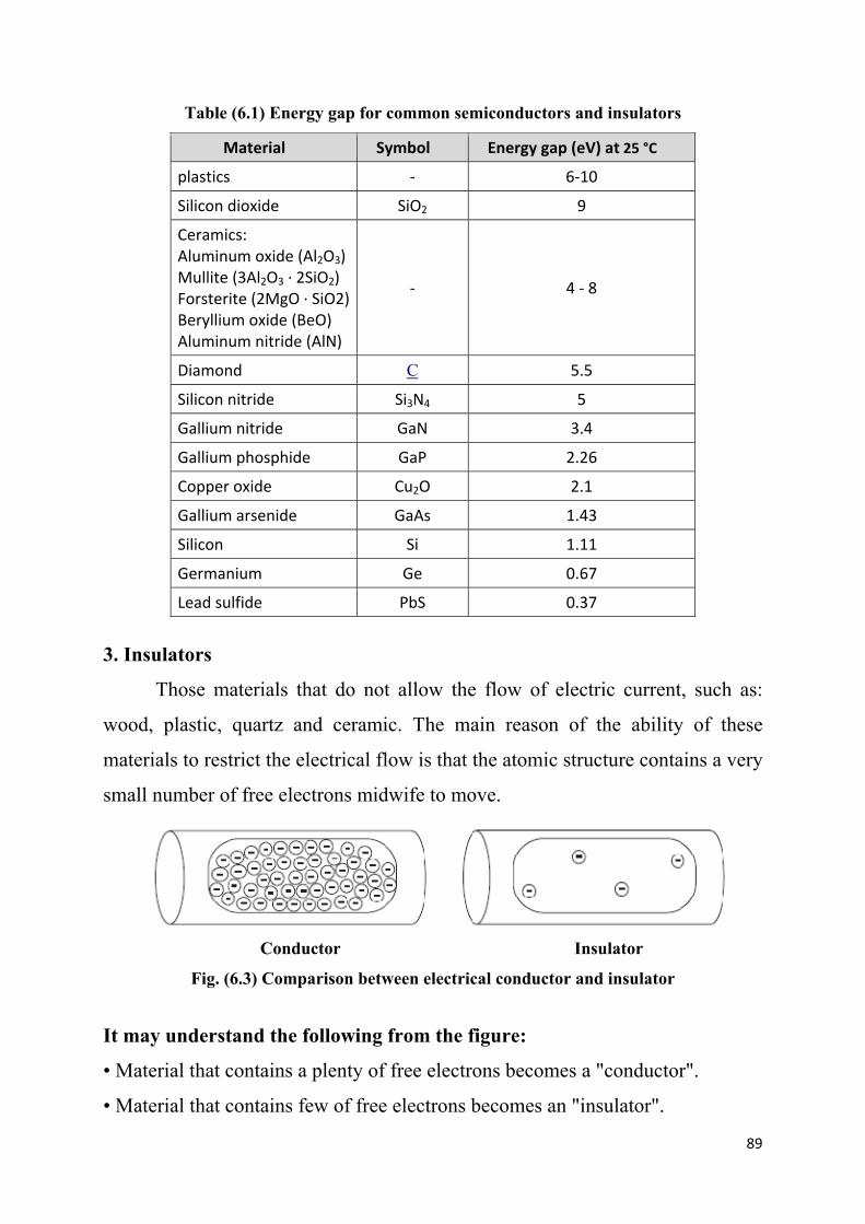
89
Table (6.1) Energy gap for common semiconductors and insulators
Material Symbol Energy gap (eV) at 25 °C
plastics ‐ 6‐10
Silicon dioxide SiO2 9
Ceramics: Aluminum oxide (Al2O3) Mullite (3Al2O3 · 2SiO2) Forsterite (2MgO · SiO2) Beryllium oxide (BeO) Aluminum nitride (AlN)
‐ 4 ‐ 8
Diamond C 5.5
Silicon nitride Si3N4 5
Gallium nitride GaN 3.4
Gallium phosphide GaP 2.26
Copper oxide Cu2O 2.1
Gallium arsenide GaAs 1.43
Silicon Si 1.11
Germanium Ge 0.67
Lead sulfide PbS 0.37
3. Insulators
Those materials that do not allow the flow of electric current, such as:
wood, plastic, quartz and ceramic. The main reason of the ability of these
materials to restrict the electrical flow is that the atomic structure contains a very
small number of free electrons midwife to move.
Conductor Insulator
Fig. (6.3) Comparison between electrical conductor and insulator
It may understand the following from the figure:
• Material that contains a plenty of free electrons becomes a "conductor".
• Material that contains few of free electrons becomes an "insulator".

90
The electric field still active even in an insulating material, where an
imbalance occurs and the positive charges attract to the electric field while the
negative charges displace away. This separation between electrical charges
generates the so-called "dipole" and the corresponding process called
"polarization". The insulator that can be polarized by an applied electric field is
called "dielectric material".
6.3 Types of Electrical Insulators
There are many types of insulators in electrical systems for various
purposes and uses. Examples of electrical insulation materials are: plastics,
rubber, wood, ceramics, glass, cellulose paper, and oils. Electrical insulators
could be classified according to its application as following:
1. Plastic materials for wiring
Plastics are used to cover the electrical wires and to protect against
electrical shock. Twisted pair cables usually insulated with
polytetraflouroethylene. Plastic materials that ideal for electrical insulation
including: PVC, PP , PEEK , PTFE, PET, PES, PEI, ECTFE, PBT, FE
2. Electrical insulators for overhead transmission lines
The insulator should be able to withstand high working voltage, the over
voltages due to lightning, and it should posses high mechanical strength to bear
the conductor load under worst leading conditions. It also, needs to have a high
resistance to temperature changes to reduce damage from power flashover.
Porcelain, silicon and glass are commonly used for overhead lines discs. There
are three main types of insulators used for overhead lines.
1. Pin type: this type is supported on a forged steel pin which is secured to the
cross arm of the supporting structure.
2. Suspension type: A suspension insulator consists of a number of separate
insulator disc units connected with each other by metal lines to form a flexible
string or chain.

91
3. Strain (tension) type: Strain or tension insulators are design for handling
mechanical stresses at angle positions where there is a change in the direction of
the line or at termination of the lines.
3. Insulating oils
These oils are stable at high temperatures and have excellent electrical
insulating properties. Oils are used in transformers, high-voltage capacitors and
fluorescent lamp ballasts.
4. Powder coating
Powder coating technology is recognized as a superior method of
applying a protective finish on numerous shapes and sizes, as opposed to wet
applications. One approach that is effectively used as a high dielectric insulator
on copper or aluminum conductors is epoxy powder coating. It is used to ensure
consistent insulation barrier due to its durability. Epoxy powder coating negates
concerns of cut-through or high-voltage spikes in cable insulations. The surface
requires cleaning and drying prior to the powder application.
Fig. (6.4) Powder coating
5. Insulating varnishes
Varnish is used as sealant. Organic varnishes and solventless resins are
widely used as insulators for electrical motors. They offer many advantages like:
- Improving the dielectric properties.
- Increasing the mechanical bonding to the winding wire.
- Protection to the winding against moisture and chemical corrosion

92
6. Capacitors
A capacitor (originally known as a condenser) is a passive two-
terminal electrical component used to store electrical energy in the form of
an electrostatic field. It consisting from two electrical conductors (plates)
separated by a dielectric (insulator) that can store energy by polarization. The
conductors are metal foils or conductive electrolyte. A dielectric could be glass,
ceramic, plastic film, air, vacuum, paper, mica, polymer or oxide layer.
6.4 Properties of Electrical Insulators
1. Resistance: is the ability of the material to repel the electrical current. The
resistance of a given conductor depends on the material it is made of and on its
dimensions. For a given material, the resistance is given by:
ρ = the resistivity of the material (ohm.m)
L = length of the wire (m)
A = cross-sectional area of the wire (m2)
Fig. (6.5) A piece of resistive material

93
Resistivity is the property that distinguishes the insulators, where
insulators have higher resistivity than semiconductors or conductors. Some
materials such as glass, paper and Teflon, which have high resistivity, are very
good electrical insulators. A much larger class of materials, even though they
may have lower bulk resistivity, are still good enough to prevent significant
current from flowing at normally used voltages, and thus are employed as
insulation for electrical wiring and cables. Examples include
rubber, polymers and most plastics.
Table (6.2) Resistivity for common materials
Material ρ (Ω∙m) at 25 °C Material ρ (Ω∙m) at 25 °C
Carbon (graphene) 1.00×10⁻⁸ GaAs 1.00×10⁻³ to 1.00×10³
Silver 1.59×10⁻⁸ Germanium 4.60×10⁻¹
Copper 1.68×10⁻⁸ Water 2.00×10⁻¹
to 2.00×10³
Aluminum 2.82×10⁻⁸ Silicon 6.40×10²
Tungsten 5.60×10⁻⁸ Wood (damp) 1.00×10³ to 1.00×10⁴
Zinc 5.90×10⁻⁸ Glass 1.00×10¹¹ to 1.00×10¹⁵
Nickel 6.99×10⁻⁸ Rubber 1.00×10¹³
Iron 1.00×10⁻⁷ Sulfur 1.00×10¹⁵
Tin 1.09×10⁻⁷ Air 1.30×10¹⁶ to 3.30×10¹⁶
Lead 2.20×10⁻⁷ Quartz 7.50×10¹⁷
Titanium 4.20×10⁻⁷
Polyethylene terephthalate (PET)
1.00×10²¹
Mercury 9.80×10⁻⁷ Teflon 1.00×10²³ to 1.00×1025
Carbon (amorphous)
5.00×10⁻⁴ to 8.00×10⁻⁴ Ceramics 1.00×10¹² to 1.00×10¹⁴

94
2. Permittivity: is a measure of how an electric field affects
a dielectric medium. In other words, the permittivity of a medium describes how
much electric field is generated per unit charge in that medium. More electric
flux exists in a medium with a low permittivity because of polarization effects.
The best insulator is that which has a large permittivity. Since the increasing of
the permittivity leads to increase the capacitance of the material, hence it could
say that the permittivity increases the ability of the insulation to absorb more
amounts of electrical charges and avoid the transfer of energy. Permittivity
relates to the ability of material to resist an electric field. In SI units,
permittivity (ε) is measured in farads per meter (F/m).
Permittivity is directly related to electric susceptibility, which is a
measure of how easily a dielectric polarizes in response to an electric field, as
following:
χ = electric susceptibility
ε0 = vacuum permittivity (8.85×10⁻¹² F/m)
H.W. Using the equation above; prove that for a vacuum χ = 0
In engineering applications, permittivity is often expressed in relative,
rather than in absolute terms. The relative permittivity of the material is also
called the "dielectric constant", thus:
r = / o
εr = relative permittivity of the material

95
Table (6.3) Relative permittivity (dielectric constant) for common materials
Material
Vacuum 1.0
Air 1.0006
Conductive polymers 2-12
Wood 2-6
PTFE/Teflon 2.1
Polypropylene 2.2-2.36
Polyethylene 2.25
Polystyrene 2.4-2.7
Carbon disulfide 2.6
Polyimide 3.4
Paper 3.85
Silicon dioxide 3.9
FR-4 4.0
Concrete 4.5
Pyrex 4.7
Glass 3.7-10
Rubber 7
Diamond 5.5-10
Salt 3-15
Graphite 10-15
Silicon 11.7
Water (200 oC) 34.5
Water (20 oC) 80.1
Water (0 oC) 88
Calcium Copper Titanate (CCT) 1000 - 100000
3. Polarization: is the ability of insulating material to undergo the separation
between electrical charges and its strength. All insulators become electrically
conductive when a sufficiently large voltage is applied that the electric field
extracts the electrons away from the atoms. This is known as "breakdown
voltage" of an insulator. Hence, "dielectric strength" is the maximum electric
field that an insulating material can withstand under ideal conditions without
breaking down. Breakdown voltage gradient is usually expressed, as voltage
drop per unit length (V/m), to measure the dielectric strength of the insulator.

6.5 En
1. Cap
A
are cha
Voltag
V
Where
Q
C
Voltag
V
Where
D
ε
Thus;
Mater
Air
Alumi
Glass
Silicon
Polyst
Polyet
Neopr
Distille
Fused
Waxe
PTFE
Mica
Diamo
Vacuu
ngineering
pacitors
Assume tw
arged by p
ge between
V = Q / C
e:
Q = charg
C = capac
ge is also g
V = D d /
e:
D = field
ε = absolu
C =
Table (6.4)
ial
na
ne oil, mine
tyrene
thylene
rene rubber
ed water
d silica
d paper
,Teflon
ond
um
g Calculat
wo paralle
positive (+
n plates (V
C
ges (coulom
citance bet
given by:
ε
density (c
ute permitt
= ε A / d
) Dielectric
eral oil
r
tions
el plates o
+Q) and n
V) is given
mb)
tween two
coulomb/m
tivity (F/m
c strength f
of area (A
egative (-
n by:
o plates
m2) = Q / A
m)
for common
Dielectric S
3.0
13.4
9.8 - 13.8
10 - 15
19.7
19 - 160
15.7 - 26.7
65 - 70
25–40
40 - 60
20 - 173
118
2000
10
), separate
Q) charge
A
n materials
Strength (M
7
ed by a sm
es, as show
Fig. (6.6
s
V/m)
mall distan
wn in figu
6) Capacitor
96
nce (d),
ure. The
r

97
Example: It is required to manufacture a capacitor of 17x10-9 coulomb/m2 field
density under 2.4 V between plates of 1 cm x 2 cm area and spaced 3 mm apart.
Select the proper dielectric material used for this capacitor.
Solution:
V = D d / ε or ε = D d / V = 17x10-9 x 3 x10-3 / 2.4 = 21.25 x10⁻¹² F/m
r = / o = 21.25 x10⁻¹² / 8.85×10−12 = 2.4
From permittivity table we find that the material is polystyrene.
H.W.: It is required to manufacture a capacitor of 12x10-9 coulomb/m2 field
density under 3 V between plates of 1 cm x 2 cm area and spaced 2 mm apart.
Select the proper dielectric material used for this capacitor.
2. Insulation discs
The major aspect in designing the discs for power transmission line is
choosing its insulation level which has a considerable influence on the cost as
well as operating reliability. The insulation disc is mainly related to the working
voltage. A transmission line transmits electrical energy from generating station
to distributing station. This voltage is usually about 11KV or 33KV. If the
power is transmitted at these voltages for long distance, the power loss would be
large. Therefore this voltage is stepped up to higher value by using step-up
transformers. The various voltages adopted by different countries for long
distance transmission lines are: 66 KV, 132 KV, 220 KV, 275 KV, 345 KV, 380
KV and 400 KV, as shown in table below. The number of insulator discs (string)
should satisfies a balance between the chances of failure and the cost of greater
insulation strength.

98
Table (6.5) Table for voltage selection
Table (6.6) Selection of insulation discs

99
Example: Calculate the number of insulated discs required to overcome
working voltage of 220 KV in a wet region. Use SF = 1.75.
Solution:
Safety voltage = 1.75 x 220 = 385 KV
So, from the table, No. of discs = 11


