
INTAKE PORT FLOW STUDY ON VARIOUS CYLINDER HEAD USING
FLOWBENCH
MOHD TAUFIK BIN ABD KADIR
UNIVERSITI MALAYSIA PAHANG
INTAKE PORT FLOW STUDY ON VARIOUS CYLINDER HEAD USING
FLOWBENCH
MOHD TAUFIK BIN ABD KADIR
A report is submitted in partial fulfillment
of the requirements for the award of the degree of
Bachelor of Mechanical Engineering with Automotive Engineering
Faculty of Mechanical Engineering
Universiti Malaysia Pahang
NOVEMBER 2008
SUPERVISOR DECLARATION
We hereby declare that we have checked this project and in our opinion this project is
satisfactory in terms of scope and quality for the award of the degree of Bachelor of
Mechanical Engineering with Automotive Engineering.
Signature :
Name of Supervisor: Mr. Fairusham
Position:
Date:
Signature:
Name of Panel:
Position:
Date:

STUDENT DECLARATION
I declare that this thesis entitled “Intake Port Flow Study on Various Cylinder Head
Using Flowbench” is the result of my own research except as cited in the reference.
The thesis has not been accepted for any degree and is not concurrently submitted in
candidature of any other degree.
Signature : ..............................................
Name : Mohd Taufik Bin Abd Kadir
Date : …………………………….

Dedicated to my beloved Parents and Family,
Especially to my late Mother,
Thank you for all the supports and encouragement during
This thesis is being made..
ACKNOWLEDGEMENTS
In the name of ALLAH SWT, the most Gracious, who has given me the
strength and ability to complete this study. All perfect praises belong to ALLAH
SWT, lord of the universe. May His blessing upon the prophet Muhammad SAW and
member of his family and companions.
I feel grateful to Allah S.W.T because this project has successfully
completed. In completion this final year project, I was in contact with many people
that contributed toward my understanding and problem solving. In particular, I wish
to express my sincere appreciation to my project supervisor, Mr. Ismail Bin Ali for
his guidance, advice and encouragement. I am deeply thankful to everyone who
assisted me on this project especially to all staff FKM laboratory for their assistance
and support.
Besides that, I also would like to dedicate my deepest appropriation to all my
fellow friends especially to automotive student batch 04/08 for their support and
encouragements during this project are performed.
Not forgetting my family members in giving me lots of supports in the
aspects of moral, social and financial during my degree. This project definitely not
exists without full encouragement from them.

ABSTRACT
Modification on intake port flow by enlarging the intake port area can
increase engine performance. Higher air flow rate entered the intake port resulting
higher air-fuel rate burn thus increased the performance of the engine. This report are
consist of experiment of intake port flow between two cylinder head, Toyota 4AGE
1.6L and Proton 4G92 1.6L.Modification works will be porting, polishing, removing
valve guide and additional mounted velocity stack. Effects of modification through
both cylinder head are experimentally tested by opening valve lift with significant
value by calculations using Superflow® SF-1020 Flowbench machine. The
experiment will consist of intake valve flow rate, the effect of velocity stack and
swirl motion in bore. It is proved by experiment result that porting, polishing and
removal valve guide in the intake port area works significantly increased the flow
into the engine and consequently changes the swirl speed to a higher values for both
cylinder head and tremendous increased when the velocity stack is added along with
the modification works.

ABSTRAK
Modifikasi pada bahagian kemasukan aliran jisim udara dengan pembesaran
kawasan kemasukan aliran udara boleh meningkatkan prestasi enjin. Peningkatan
kenaikan kadar kemasukan jisim udara meningkatkan kadar pembakaran jisim udara
dan bahan bakar yang mengakibatkan peningkatan mendadak prestasi enjin. Repot
experimen ini mengandungi kajian tentang kadar jisim udara masuk antara dua jenis
kepala silinder iaitu Proton 4G92 1.6L dan Toyota 4AGE 1.6L.Kerja-kerja
modifikasi adalah seperti ”porting”, ”polishing”, penghapusan panduan injap udara
masuk dan penambahan cerobong kelajuan.Kesan daripada modifikasi kedua-dua
kepala silinder akan diuji keberkesanannya melalui experimen dengan pembukaan
injap udara masuk melalui pengiraan kadar pembukaan injap udara masuk dengan
menggunakan mesin Superflow® SF-1020 Flowbench.Experimen pada ruang aliran
jisim udara masuk ini merangkumi kadar jisim udara masuk, kesan penggunaan
cerobong kelajuan dan kesan pergerakan pusaran pada bor.Telah terbukti dalam
experimen bahawa kesan daripada kerja-kerja ”porting”, ”polishing” dan
penghapusan panduan injap udara masuk di kawasan kemasukan aliran udara dapat
meningkatkan kadar jisim udara yang masuk ke dalam kepala silinder
mengakibatkan perubahan kadar kelajuan pusaran di dalam bor kepada kedua-dua
kepala silinder and peningkatan yang menakjubkan jika modifikasi disertakan juga
dengan cerobong kelajuan udara.

TABLE OF CONTENTS
CHAPTER TITLE PAGE
THESIS TITLE i
DECLARATION ii
DEDICATION iii
ACKNOWLEDGEMENT v
ABSTRACT vi
TABLE OF CONTENT viii
LIST OF TABLES xi
LIST OF FIGURES xii
LIST OF SYMBOLS xiv
LIST OF APPENDICES xv
CHAPTER I INTRODUCTION 1
1.0 Project Background 1
1.1 Problem Statement 2
1.2 Objectives of the Project 2
1.3 Scopes of the Project 3
CHAPTER II LITERATURE STUDY 5
2.1 Introduction 5
2.2 Engine Specification 6
2.2.1 Intake Port Design 6
2.2.2 Poppet Valve Design 7
2.3 Intake Port Flow 7
2.4 Flow Losses in an Intake Port 11
2.5 Technique of Modifications 12
2.6 Swirl 13
2.6.1 Swirl Meter 14
2.7 Coefficient of Discharge 15
2.8 Flowbench system 17
CHAPTER III METHODOLOGY 19
3.1 Porting 19
3.1.1 Porting Tools 20
3.2 Polishing 23
3.2.1 Polishing Tools 23
3.2.2 Polishing Work 24
3.3 Velocity Stack 25
3.4 L/D Ratio 27
3.4.1 L/D Ratio for Both Cylinder Head 28
3.5 Flowbench Analysis 28
3.5.1 Analysis Parameter 30
3.5.2 Valve Lift Actuations 31
3.5.3 Steps for Measurement 32
3.6 Analysis for Both Engines 34
3.7 Airflow Measurement 35
3.8 Formula Used 35
CHAPTER IV RESULT AND DISCUSSIONS
4.1 Proton Intake Port Result 38
4.1.1 Before Cleaning Process 38
4.1.2 After Cleaning Process 39
4.1.3 Modification without Velocity Stack 40
4.1.4 Modification with Velocity Stack 41
4.1.5 Swirl Result 42
4.1.6 Valve Flow Percentage Increment 43

4.17 Expected Horsepower 44
4.2 Toyota Intake Port Result 45
4.2.1 Before Cleaning Process 45
4.2.2 After Cleaning Process 46
4.2.3 Modification without Velocity Stack 47
4.2.4 Modification with Velocity Stack 48
4.2.5 Swirl Result 49
4.2.6 Valve Flow Percentage Increment 50
4.2.7 Expected Horsepower 52
4.3 Analysis Comparison between Proton and 53
Toyota Intake Port Result
CHAPTER V CONCLUSION AND RECOMMENDATIONS 57
5.1 Conclusions 57
5.2 Recommendations 59
REFERNCES 61
APPENDIX A-H 62-94
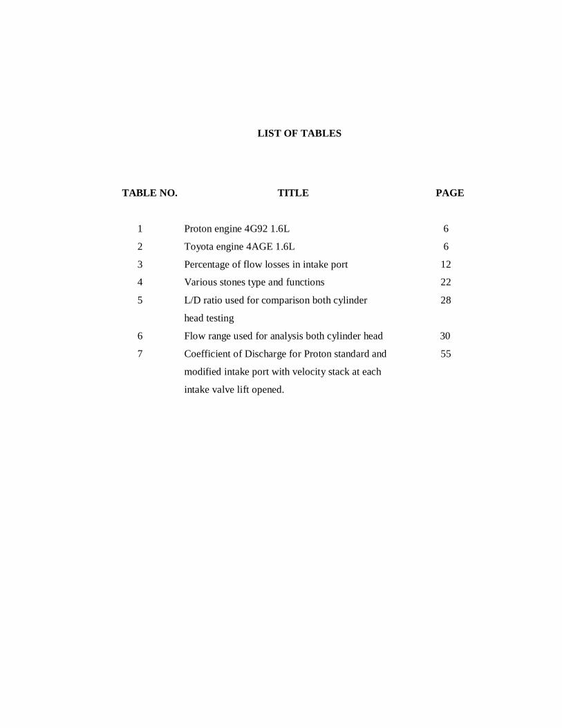
LIST OF TABLES
TABLE NO. TITLE PAGE
1 Proton engine 4G92 1.6L 6
2 Toyota engine 4AGE 1.6L 6
3 Percentage of flow losses in intake port 12
4 Various stones type and functions 22
5 L/D ratio used for comparison both cylinder 28
head testing
6 Flow range used for analysis both cylinder head 30
7 Coefficient of Discharge for Proton standard and 55
modified intake port with velocity stack at each
intake valve lift opened.

LIST OF FIGURES
FIGURE NO TITLE PAGE 1 Flow chart of the project 4
2 Proton intake port design 7
3 Toyota intake port design 7
4 First Stage of valve lift operation 8
5 Second stage of valve lift operation 9
6 Final stage of valve lift operation 10
7 Flow losses in the intake port 11
8 Swirl direction view from top 13
9 Swirl meter used for swirl experiment 14
10 Flow region in low intake valve lift open 16
11 Flow region in intermediate valve lift open 16
12 Flow region in high intake valve open 17
13 Schematic of Flowbench layout 17
14 Proton intake port after porting works 20
15 Toyota intake port after porting works 20
16 Air grinder for porting modification 21
17 W179 cylindrical type abrasives 23
18 Flapwheel used for polishing works 23
19 Roll of cloth that used for polishing 24
20 A25 ball type abrasives tool 24
21 Proton intake port after polishing modification 24
22 Toyota intake port after polishing modification 25
23 Velocity stack that mounted to Proton intake port 26
24 Velocity stack that mounted to Toyota intake port 26
25 Superflow® SF-1020 Flowbench machine 29
26 Valve lift adapter for Toyota experiment 31
27 Test analysis is performed 33
28 Dial gauge position 33
29 Valve flow versus valve lift for Proton standard 38

intake port before cleaning.
30 Valve flow versus valve lift for Proton standard intake 39
port after cleaning
31 Valve flow versus valve lift for Proton standard and 40
modification intake port without velocity stack
32 Valve flow versus valve lift for Proton standard and 41
modified intake port with velocity stack
33 RPM versus L/D ratio for Proton standard and modified 42
intake port without velocity stack
34 Flow percentage versus valve lift for Proton porting 43
and polishing with standard intake port results
35 Horsepower versus valve lift for Proton porting and 44
polishing with standard intake port results.
36 Valve flow versus valve lift for Toyota standard intake 45
port before cleaning
37 Valve flow versus valve lift for Toyota standard intake 46
port after cleaning
38 Valve flow versus valve lift for Toyota standard and 47
modified intake port without velocity stack
39 Valve flow versus valve lift for Toyota standard and 48
modified intake port with velocity stack
40 RPM versus valve lift for Toyota standard and 49
modified intake port without velocity stack
41 Valve flow increment versus valve lift for Toyota 50
porting and polish intake port with standard
intake port results.
42 Flow increment versus valve lift for Toyota 52
porting and polish with standard intake port results.
43 Valve flow versus L/D ratio for Proton and Toyota 54
porting and polishing intake port results
44 Coefficient of Discharge(CD) versus Valve lift for 56
Toyota standard and modified intake port with
velocity stack

LIST OF SYMBOLS
Am - Minimum area
Lv - Valve lift
β - Valve seat angle
Dv - Valve head diameter
w - Seat width
Dm - Mean seat diameter
Dp - Port diamater
Ds - Valve stem diameter
RPM - Revolution per minute
cfm - Cubic feet per minute
CD - Coefficient of discharge
lps - Liter per second
in - inch
mm - millimeter
cm - centimeter
cmh - cubic meter per hour
MEP - Mean effective pressure
HP - Horsepower
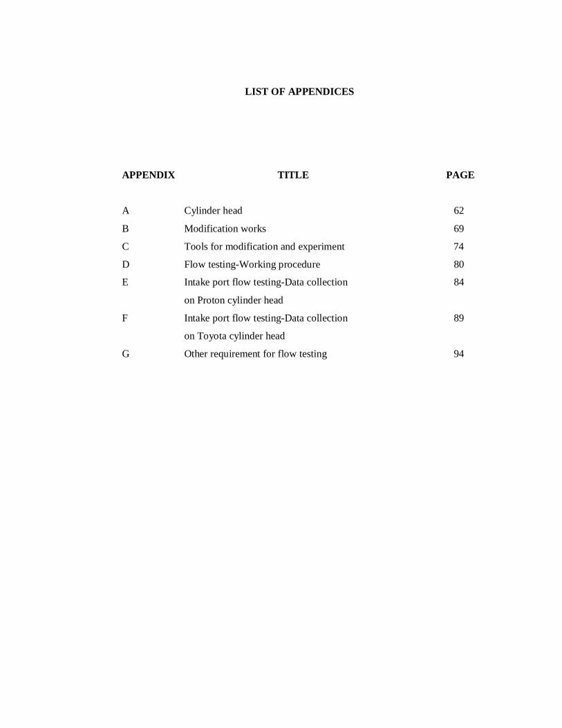
LIST OF APPENDICES
APPENDIX TITLE PAGE A Cylinder head 62
B Modification works 69
C Tools for modification and experiment 74
D Flow testing-Working procedure 80
E Intake port flow testing-Data collection 84
on Proton cylinder head
F Intake port flow testing-Data collection 89
on Toyota cylinder head
G Other requirement for flow testing 94

CHAPTER 1
INTRODUCTION
1.0 Project Background
The myth of modifying cylinder head to optimize the horsepower and air-
flow of the engine are not impossible this day. Modifying the intake port have many
types and rules. It is such as valve guide removed, porting, polishing and mounting
velocity stack. All modifiers, modified cylinder head to have an increasing increment
of horsepower and air-flow and thus the engine efficiency will be increase too.
The flow of the intake port is measured by coefficient of discharge(CD) and
the increasing of horsepower produced. A wide variety of inlet port geometry
patterns will affected the amount of air entered the port.
This investigation studied were strictly to know the effect of cylinder head
modification to improve horsepower .The effectiveness cylinder head geometry of
the intake port for both cylinder head testing will be compared by using lift over
diameter ratio(L/D ratio).Performance parameters will be analyze through data
collecting from Flowbench and Swirl meter machine.

1.1 Problem statement
Considering the flow through intake port as a whole, the greatest loss must be
downstream of the valve due to the lack of pressure recovery. Because of that, this
studies to investigate the flow characteristics of the both two cylinder head. We need
to know how much performance difference the Toyota cylinder head compared to the
Proton cylinder head. This will be the basis for conclusion regarding this works.
This study also concern about the improvement of the power itself compare
to the old cylinder head of both engine and how much the increment of power that
will relies when this analysis on improvement of both cylinder head. Means that, the
power output as a result the port airflow effect from the modification port that has
been done is what the most importance to be known.
The flow itself is calculated by using the term of horsepower. High airflow
enters the intake port area also increases the horsepower. The term of comparison is
what the importance parameters that must be taken care of. It will show the
improvement of flow for both cylinder head. Because of that the standard analysis is
used to compare both cylinder head so that this study analysis can be guidance for
any improvement or analysis to both cylinder head.
1.2 Objectives of the project
1) Analysis intake port for types of flow at two cylinder head engine that is
Toyota 4AGE 1.6L and Proton 4G92 1.6L.
2) To determine how much power improvement at the modified intake port
compared to the original intake port.

1.3 Scopes of the project
1) Analysis and comparison for measure air flow at both cylinder head at the
intake port for Toyota 4AGE 1.6L and Proton 4G92 1.6L.
2) Using Superflow SF-1020 Flowbench machine to measure the flow rate
through 4 different intake port conditions.
3) Modify intake port using 3 method that is porting, polish and additional
velocity stack.
4) Identify the increasing performance after the modification works done.
5) The flow and swirl testing results will not be compared to specification of
both engines from the manufacturer.

THESIS FLOW CHART
Intake port flow study on various cylinder head using Flowbench
FYP 1 FYP 2 no yes
Figure 1: Flow chart of the project
Literature Study & Analysis
Methodology
Flowbench Testing
Intake port Toyota 4AGE 1.6L Intake port Proton 4G92 1.6L
Airflow performance comparison
Result?
Discussion and result
Conclusion and Recommendation
start
Introduction
Original Original
Porting Porting
Polish Polish
Velocity stack Velocity stack
End

CHAPTER 2
LITERATURE STUDY 2.1 Introduction
Automotive industries nowadays have enlarged in impressive ways. The
internal combustion engine first developed at year 1876 until now, the engines have
continued to develop as the knowledge of engine processes has increased, where new
technologies have been invented and available as the demand for new cars and new
engine arose.
Modification to the engine without additional system attach to the engine
operation were the best solution to have an optimum engine operation in term of
torque and horsepower. To optimize the power and intake port flow produce by the
engine modification were through a very limited value. The value is limited due to
the restricted area of the engine production by the manufacturer.
Analysis on the cylinder head is consist of Toyota 4AGE 1.6L 16-valve
DOHC and Proton 4G92 1.6L 16-vave SOHC engine .Flow that through the intake
port will show the differences between both of the cylinder head. High flow of fuel
that can enter the cylinder head will determined the performance of the engine. The
performance can be defined by the terms flow and horsepower.
Both cylinder head will be analyzed by using the flow machine SF-1020
Flowbench. The cylinder head is bolted to the cylinder block and covers the top of
the cylinder bores. Type of cylinder head will determined for better breathing,
improved combustion and more efficient, lighter valve rains-reduced inertia allowing
higher engine operating speed. It also shows how much the swirl in the combustion
chamber. The term swirl is the name of organized movement of the air and fuel
mixture in the cylinder. Then generate more power because of higher mixture than
make the fuel burn perfectly.
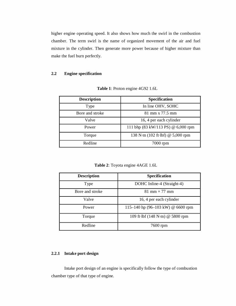
2.2 Engine specification
Table 1: Proton engine 4G92 1.6L
Description Specification Type In line OHV, SOHC
Bore and stroke 81 mm x 77.5 mm Valve 16, 4 per each cylinder Power 111 bhp (83 kW/113 PS) @ 6,000 rpm
Torque 138 N·m (102 ft·lbf) @ 5,000 rpm
Redline 7000 rpm
Table 2: Toyota engine 4AGE 1.6L
Description Specification
Type DOHC Inline-4 (Straight-4)
Bore and stroke 81 mm × 77 mm
Valve 16, 4 per each cylinder
Power 115–140 hp (96–103 kW) @ 6600 rpm
Torque 109 ft·lbf (148 N·m) @ 5800 rpm
Redline 7600 rpm
2.2.1 Intake port design Intake port design of an engine is specifically follow the type of combustion
chamber type of that type of engine.

Figure 2: Proton intake port design
Figure 3: Toyota intake port design 2.2.2 Poppet valve design
There are several types of valves that are used: a poppet, rotary, disc and a
sleeve. The most common valve is the poppet valve. The poppet valve is inexpensive
and has good sealing properties, making it such a popular choice.
2.3 Intake port flow
In the cylinder head, the importance parts to increased the performance is the
intake and exhaust port. The importance of both port effect the performance of the
engine and also the engine efficiency. The instantaneous valve flow area depends on
valve lift and the geometric details of the valve head, seat and stem. There are 3
separates stages to the flow area developments valve lift increases[1].
The stages are :
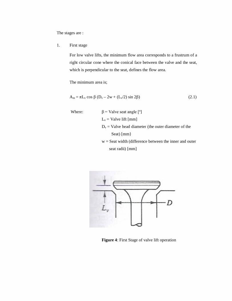
1. First stage
For low valve lifts, the minimum flow area corresponds to a frustrum of a
right circular cone where the conical face between the valve and the seat,
which is perpendicular to the seat, defines the flow area.
The minimum area is;
Am = πLv cos β (Dv – 2w + (Lv/2) sin 2β) (2.1)
Where: β = Valve seat angle [º]
Lv = Valve lift [mm]
Dv = Valve head diameter (the outer diameter of the
Seat) [mm}
w = Seat width (difference between the inner and outer
seat radii) [mm]
Figure 4: First Stage of valve lift operation
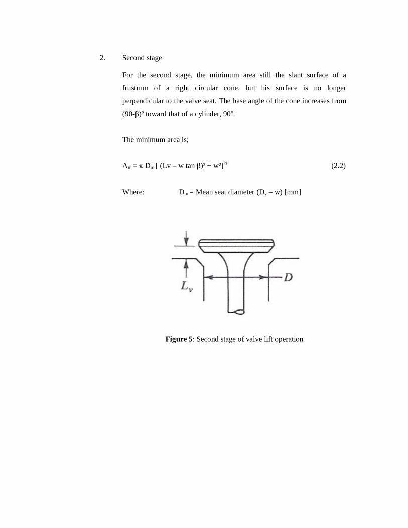
2. Second stage For the second stage, the minimum area still the slant surface of a
frustrum of a right circular cone, but his surface is no longer
perpendicular to the valve seat. The base angle of the cone increases from
(90-β)º toward that of a cylinder, 90º.
The minimum area is;
Am = π Dm [ (Lv – w tan β)² + w²]½ (2.2)
Where: Dm = Mean seat diameter (Dv – w) [mm]
Figure 5: Second stage of valve lift operation
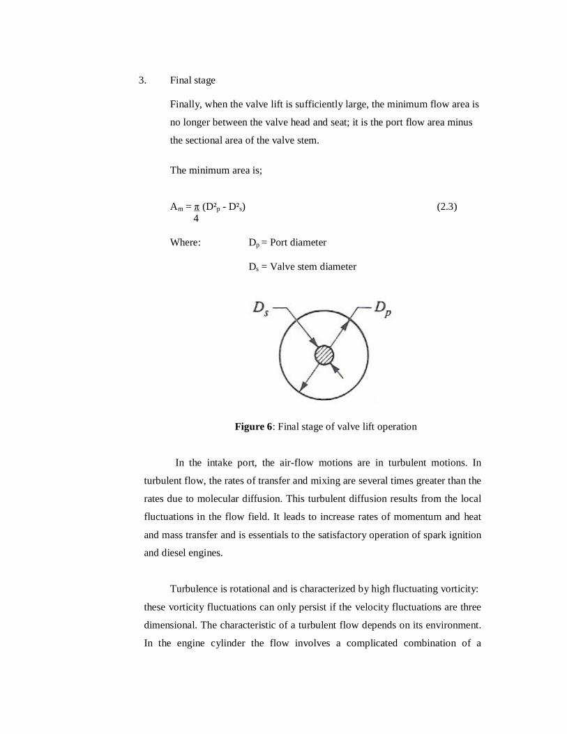
3. Final stage Finally, when the valve lift is sufficiently large, the minimum flow area is
no longer between the valve head and seat; it is the port flow area minus
the sectional area of the valve stem.
The minimum area is;
Am = π (D²p - D²s) (2.3) 4 Where: Dp = Port diameter Ds = Valve stem diameter
Figure 6: Final stage of valve lift operation
In the intake port, the air-flow motions are in turbulent motions. In
turbulent flow, the rates of transfer and mixing are several times greater than the
rates due to molecular diffusion. This turbulent diffusion results from the local
fluctuations in the flow field. It leads to increase rates of momentum and heat
and mass transfer and is essentials to the satisfactory operation of spark ignition
and diesel engines.
Turbulence is rotational and is characterized by high fluctuating vorticity:
these vorticity fluctuations can only persist if the velocity fluctuations are three
dimensional. The characteristic of a turbulent flow depends on its environment.
In the engine cylinder the flow involves a complicated combination of a

turbulent shear layers, recirculating regions and boundary layers. But, the most
important characteristics of a turbulent flow is randomness irregularity.
2.4 Flow losses in an intake port
Figure 7: Flow losses in the intake port[1]
In order to increase the intake flow performance, the flow losses in the intake
port area must be analyzed. Those losses have restrict the mass air-flow rate entered
the intake port. Thus, the air-flow rate enter decreased. Before the modification
works is done, it needs to overcome the losses. Generally, the intake port is design to
limited with the engine bore specifications. To eliminates all the losses is impossible
and the easiest ways is to smoothen the air-flow entered and increased the intake port
scale by modification.
Referring to figure 3, the flow losses in the intake port area were describe
clearly through the losses from each part in the port. To increase the performance,
hose losses should be eliminate.
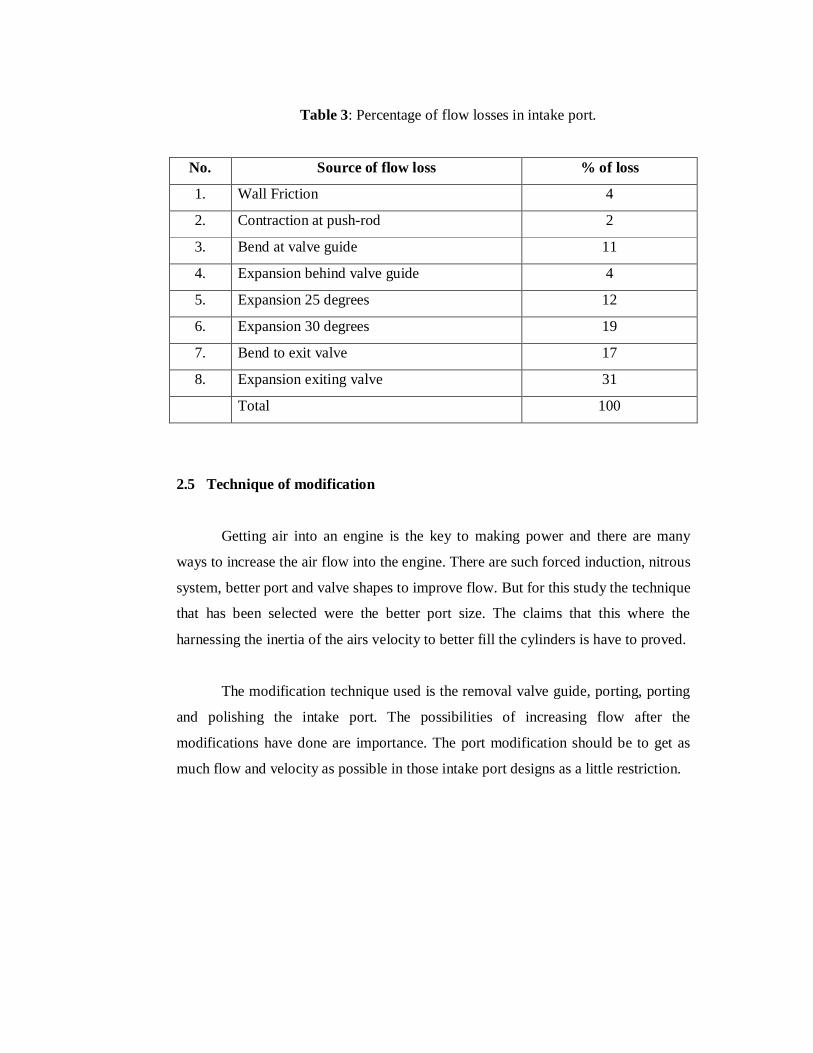
Table 3: Percentage of flow losses in intake port.
No. Source of flow loss % of loss
1. Wall Friction 4
2. Contraction at push-rod 2
3. Bend at valve guide 11
4. Expansion behind valve guide 4
5. Expansion 25 degrees 12
6. Expansion 30 degrees 19
7. Bend to exit valve 17
8. Expansion exiting valve 31
Total 100
2.5 Technique of modification
Getting air into an engine is the key to making power and there are many
ways to increase the air flow into the engine. There are such forced induction, nitrous
system, better port and valve shapes to improve flow. But for this study the technique
that has been selected were the better port size. The claims that this where the
harnessing the inertia of the airs velocity to better fill the cylinders is have to proved.
The modification technique used is the removal valve guide, porting, porting
and polishing the intake port. The possibilities of increasing flow after the
modifications have done are importance. The port modification should be to get as
much flow and velocity as possible in those intake port designs as a little restriction.

2.6 Swirl
Figure 8: Swirl direction view from top
The values of swirl are always in debate with race engine or performance
builders. A few years back, the swirl existence in the combustion chamber is the
most of engine builders feared. It causes the fuel out of the intake charge in the
cylinder due to the motion direction. However, this proved only if the effect of lower
intake charge temperatures and fuel droplets is too big. Cooler intake charges from
the thermal-barrier manifold coatings meant the fuel leaving the carb booster needed
to be more atomized. If the requirement is fulfill, the swirl motion is important.
Swirl motion is an organized rotation result from the air-flow motion in the
intake charge. The importance of existence the swirl motion is to helps mixing the
fuel and air rapidly. The swirl motion generates according to the perimeter of bore.
The rotation will continue in the combustion chamber until the combustion or
ignition process started. In this case, the swirl helps rapid air-fuel mixing and
resulting speed up of combustion process. The momentum of the swirl motion helps
increased the mixing process.
2.6.1 Swirl meter
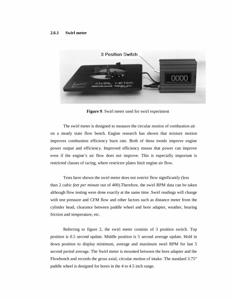
Figure 9: Swirl meter used for swirl experiment
The swirl meter is designed to measure the circular motion of combustion air
on a steady state flow bench. Engine research has shown that mixture motion
improves combustion efficiency burn rate. Both of these trends improve engine
power output and efficiency. Improved efficiency means that power can improve
even if the engine’s air flow does not improve. This is especially important is
restricted classes of racing, where restrictor plates limit engine air flow.
Tests have shown the swirl meter does not restrict flow significantly (less
than 2 cubic feet per minute out of 400).Therefore, the swirl RPM data can be taken
although flow testing were done exactly at the same time .Swirl readings will change
with test pressure and CFM flow and other factors such as distance meter from the
cylinder head, clearance between paddle wheel and bore adapter, weather, bearing
friction and temperature, etc.
Referring to figure 2, the swirl meter consists of 3 position switch. Top
position is 0.5 second update. Middle position is 5 second average update. Hold in
down position to display minimum, average and maximum swirl RPM for last 5
second period average. The Swirl meter is mounted between the bore adapter and the
Flowbench and records the gross axial, circular motion of intake. The standard 3.75”
paddle wheel is designed for bores in the 4 to 4.5 inch range.
Other features of Performance Trends’ Swirl Meter include low flow
restriction design as the same time the measurement of intake flow can be taken. It
also shows the direction of swirl, either clockwise or counterclockwise .Clockwise
directions of flow indicated by positive value while counterclockwise of flow is
negative value.
2.7 Coefficient of discharge (CD)
The coefficient of discharge (CD) is defined as the ratio of actual discharge to
ideal discharge. In the engine environment, ideal discharge considers an ideal gas
and the process to be free from friction, surface tension, etc. Coefficients of
discharge are widely used to monitor the flow efficiency through various engine
components and are quite useful in improving the performance of these components.
The engine efficiency are indicated thermal efficiency, brake thermal
efficiency, mechanical efficiency, volumetric efficiency and relative efficiency. In
this study analysis, the CD value will indicates the flow efficiency in the intake port
area.
Discharge coefficient of typical inlet poppet valve in normal operating engine
are effected by the intake valve lift opened. The discharge coefficient based on valve
curtain area is a discontinuous function of the valve lift/diameter ratio. There are 3
segments corresponds to different flow regimes. The segments are;
1. Very low lifts
The flow remains attached to the valve head and seat, giving high values
for the discharge coefficient.

Figure 10: Flow region in low intake valve lift open
2. Intermediate Lift
The flow separates from the valve head at the inner edge of the valve seat.
An abrupt decrease in discharge coefficient occurs a this point. The
discharge coefficient then increases with increasing lift since the size of
the separated region remains approximately constants while the minimum
flow area is increasing.
Figure 11: Flow region in intermediate valve lift open
Air flow Valve seat
Air flow Valve stem

3. High valve lifts
The flow separates from the inner edge of the valve seat as well.
Figure 12: Flow region in high intake valve open
2.8 Flowbench system
Figure 13: Schematic of Flowbench layout
Air flow Valve stem

The SuperFlow SF-1020 Flowbench is designed to measure air-flow
resistance of engine cylinder heads, intake manifolds, velocity stacks and restrictor
plates. For four-cycle engine testing, air is drawn through the cylinder head into the
machine, through the air pump and exits through the vents at each side of the SF-
1020 Flowbench. For two-cycle engine and exhaust valve testing, the path of air-
flow is reversed by entering an Exhaust flow range.
The test pressure meter (pressure transducer) measures the pressure or
vacuum at the base of the test cylinder. The flow meter measures the pressure
difference across an adjustable flow orifice in the SF-1020 Flowbench. The flow
meter reads 5 to 100% of any flow range selected in either intake or exhaust flow
direction. The full scale flow measurement range can be varied from 25 to 1000
cubic feet per minute, (12 to 470 liter per second). The Flowbench is fast, accurate,
repeatable result at any test pressure between 5”(13 cm) and 70”(178 cm) of water.
Testing typically performed at 50-65” of water test pressure.
Unique variable flow orifice adjust flow range between 25 cubic feet per
meter and 1000 cubic feet per meter based on FlowCom input, to fit the valve size or
the valve lift. Run test in a single setting to obtain extended accuracy at low lifts,
with readings all within 0.25%.The variable flow range increases resolution of flow
measurements versus single-range system; 0.5% changes are easily detectable.
CHAPTER 3
METHODOLOGY
3.1 Porting
Porting is an art of modification by enlarging the port to its maximum
possible size (in keeping with the highest level of aerodynamic efficiency) but those
engine are highly developed very high speed units where the actual size of the ports
has become the restriction. Methods for porting are usually with CNC-machine to
provide the basic shape of the port and hand finishing because some area of the port
is not accessible for the CNC machine. This porting process to the cylinder heads and
intake ensures that the flow mixture enters the cylinder head chamber with the
maximum amount of velocity.
The higher flow restriction in any engines is within the cylinder head. Porting
is needed for reducing the flow restriction at the particular area to increase
performance of the engine compare with the same engine with same displacement.
Higher the flow entered will causing increasing velocity of the air-flow and at the
same time the performance in case of horsepower will also affected.
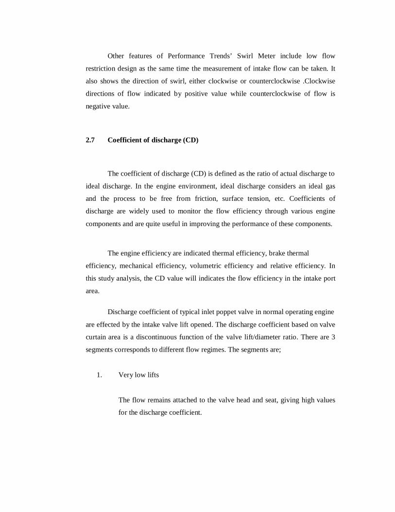
Both intake ports are modified strictly the same as how much the porting
works done is the parameter that have been fixed. Referring to figure
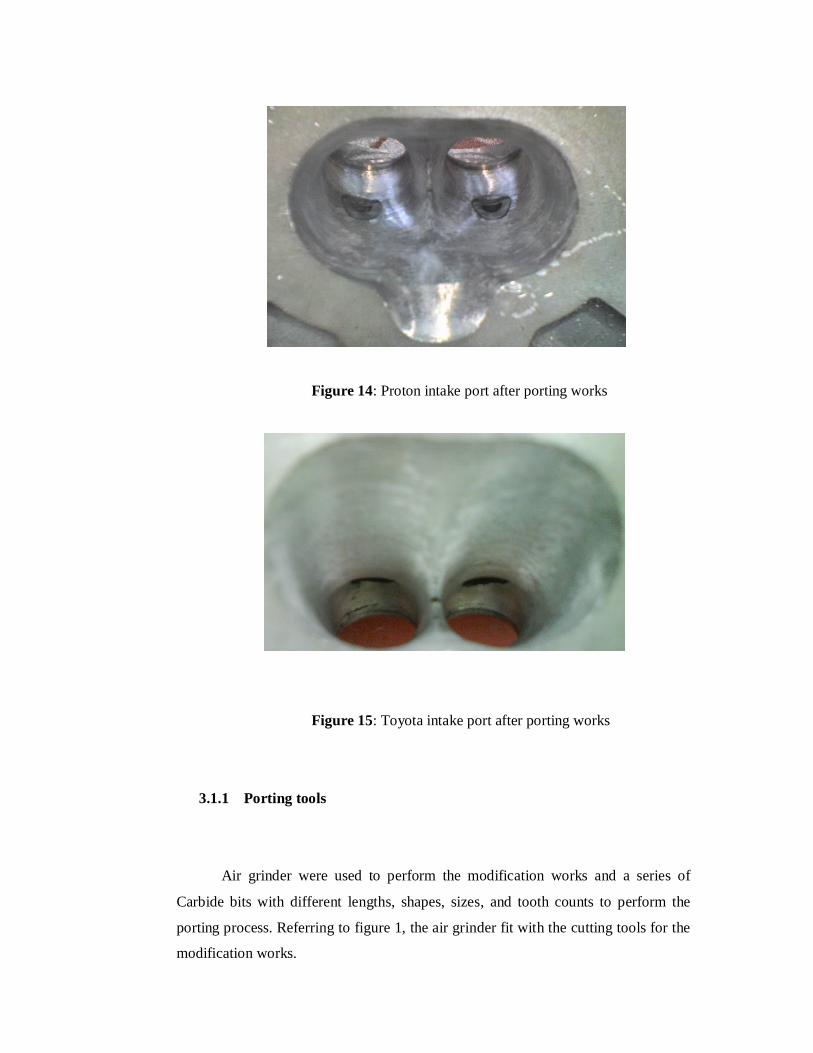
Figure 14: Proton intake port after porting works
Figure 15: Toyota intake port after porting works
3.1.1 Porting tools
Air grinder were used to perform the modification works and a series of
Carbide bits with different lengths, shapes, sizes, and tooth counts to perform the
porting process. Referring to figure 1, the air grinder fit with the cutting tools for the
modification works.

Figure 16: Air grinder for porting modification
The air grinder is used with four type of cutting tools that is cylinder type,
ball type, oval type and flame type. By referring to table 4,the required tools used for
the works is dependent on the surface of intake port.

Table 4: Various stones type and the function
Shape Use Sizes
W179 : Cylindrical
Reshape as necessary for
corners and flats of square
or rectangular ports &
sides of guide bosses
3/8 in diameter
x 1 ¼ in long
W188 : Cylindrical
Reshape as necessary for
corners and flats of square
or rectangular ports &
sides of guide bosses
½ in diameter
x 1 ½ in long
W227 : Cylindrical
Roof of combustion
chamber and combustion
chamber wall
1 ¼ in diameter
x ½ in long
A25 : Ball
For radiused ports and for
reshaping ports and valve
throat to oval.
1 in diameter x 1 in long

3.2 Polishing
Polishing is another type of modifying the cylinder head. Polishing eventually
did not give an extra breathe for horsepower. As this analysis is conducted to see the
behavior between the rough surface and the smooth surface after polishing in term of
horsepower improvement. Rough surface can give turbulent flow thus increase the
mixture of the fuel and air in combustion chamber. Smooth surface will make those
fuel evaporate as the boundary layer for smooth surface is not zero and thus the fuel
will touch the surface and increase the mixture of the air and fuel because both is in
the same phase and condition.
Polishing works done to the Proton and Toyota intake port are mostly using
Flapwheel, referring to figure 18.The other polishing works to re-smooth some sharp
edges by cylindrical, ball and roll of cloth that are made from abrasives that have
different type of abrasives soft types cab be referred to figure 17 to 20.
3.2.1 Polishing tools
Figure 17: W179 cylindrical type abrasives
Figure 18: Flapwheel used for polishing works
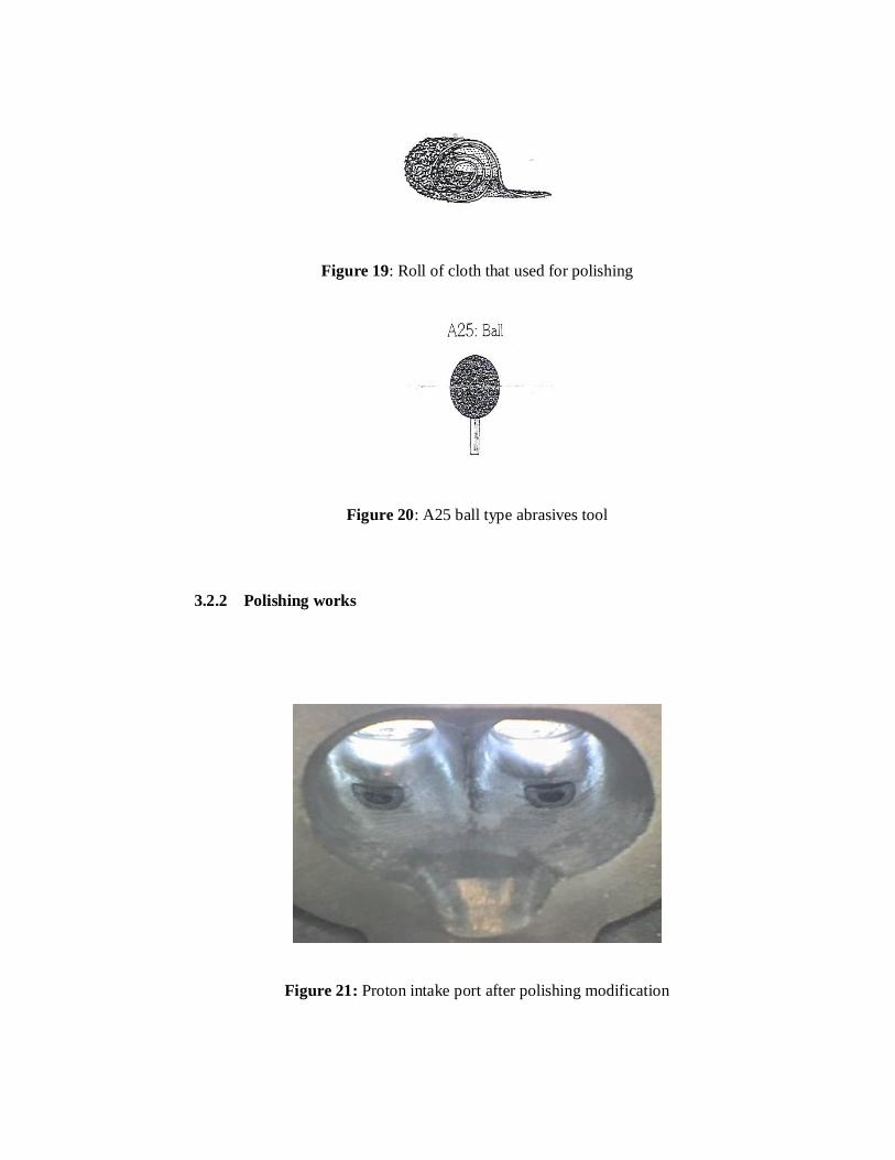
Figure 19: Roll of cloth that used for polishing
Figure 20: A25 ball type abrasives tool
3.2.2 Polishing works
Figure 21: Proton intake port after polishing modification

Figure 22: Toyota intake port after polishing modification
3.3 Velocity stack
Velocity stack is generally a cylindrical tube with a radiuses inlet end device
which is added onto the air entry location or locations of an engines intake system,
carburetor or fuel injection. It can be attached to an air box inlet or to each cylinder
in an IR (individual runner).The function of it is to allow smooth and even entry of
air into the intake duct with the flow streams boundary layer adhering to the pipe
walls. It also modifies the dynamic tuning range of the intake tract by functioning as
a small reverse megaphone which can extend the duration of pulses within the tract.
Referring to figure 23 and 24, those velocity stack used are not appropriate
because it have much more different from the actual one. The surface of home made
velocity stack are not smooth enough for comparison to the real one. But, for this
experiment it only concern about the effect of using velocity stack to the air flow rate
entered. Thus, the theory are correct and the velocity stack can increased air flow
rate.


