Cleveland State University Cleveland State University
EngagedScholarship@CSU EngagedScholarship@CSU
ETD Archive
2016
Intelligent Voice Activated Home Automation (IVA) Intelligent Voice Activated Home Automation (IVA)
Mrunal Dipakkumar Bhatt
Follow this and additional works at: https://engagedscholarship.csuohio.edu/etdarchive
Part of the Computer Engineering Commons
How does access to this work benefit you? Let us know! How does access to this work benefit you? Let us know!
Recommended Citation Recommended Citation Bhatt, Mrunal Dipakkumar, "Intelligent Voice Activated Home Automation (IVA)" (2016). ETD Archive. 900. https://engagedscholarship.csuohio.edu/etdarchive/900
This Thesis is brought to you for free and open access by EngagedScholarship@CSU. It has been accepted for inclusion in ETD Archive by an authorized administrator of EngagedScholarship@CSU. For more information, please contact [email protected].
INTELLIGENT VOICE ACTIVATED HOME AUTOMATION
(IVA)
MRUNAL DIPAKKUMAR BHATT
Bachelor of Engineering in Information Technology
University of Pune
May, 2010
Submitted in partial fulfillment of requirements for the degree
MASTER OF SCIENCE IN ELECTRICAL ENGINEERING AND
COMPUTER SCIENCE
at the
CLEVELAND STATE UNIVERSITY
May, 2016
We hereby approve this thesis of
MRUNAL DIPAKKUMAR BHATT
Candidate for the Master of Computer Science Degree
for the Department of Electrical Engineering and Computer Science
And
CLEVELAND STATE UNIVERSITY
College of Graduate Studies
Thesis Committee Chairperson, Dr. Victor Matos
Department and Date
Dr. Ben Blake
Department and Date
Dr. Sunnie S. Chung
Department and Date
Student’s Date of Defense: 05/09/2016
ACKNOWLEDGEMENTS
I would like to gratefully thank my academic and thesis advisor, Dr. Victor Matos for his
guidance, supervision and expertise throughout the course of this study. His vital inputs at
regular interval made it possible to reach the goals set for my thesis. His immense
knowledge and vision of technology makes him an ideal thesis advisor according to me.
Secondly, I offer my sincere gratitude to other committee members Dr. Ben Blake and Dr.
Sunnie Chung for their encouragement.
I would like take the opportunity to thank my friends Mr. Ravi Kandoi, Mr. Chaitanya
Lomte, Mr. Karan Katyal and Mr. Adwait Sankhe for their support and help. Also, I
would like to thank my fiancée Ms. Sonal Boraste for her motivation, support and
encouragement while working on my thesis.
This thesis would not be possible without constant support, guidance and motivation
from my parents Mr. Dipakkumar H. Lakhalani and Mrs. Malti D. Lakhalani. I cannot
thank them enough for raising me to become who I am today.
Finally, I thank my dear brother Mr. Chinmay Bhatt, who made my life happy and
uplifting.
iv
INTELLIGENT VOICE ACTIVATED HOME AUTOMATION (IVA)
MRUNAL DIPAKKUMAR BHATT
ABSTRACT
This thesis presents the design of an original Intelligent Home Automation Architecture.
My work was divided in two phases. The first portion was dedicated to acquiring a
thorough understanding of the most successful and diffused Home-Automation
commercial architectures. During this phase, I intended to gain a deep appreciation for the
variety of organizations, capabilities, limitations, and potential areas of growth of the
existing Home-Automation leading systems. In order to acquire this knowledge, I had to
use a reverse engineering approach. The reason for using this methodology arises from the
fact that all the products considered in this study are commercially protected as industrial
secrets. Consequently, it is not possible to obtain detailed descriptions of their 'real'
architectures and internal operations. The second part of this thesis presents my personal
contribution in the form of a prototype for a Smart-Home Architecture. My design, called
IVA (short for Intelligent Voice Activated) home automation, is primarily driven by the
processing of natural language voice commands. I argue that this approach should be
attractive to seniors, and people with limited range of mobility. In addition, the hardware
needed to implement the system is commonly available and inexpensive. The most
sophisticated device in my model is a smartphone, which in most cases, is already own by
the prospective user.
v
TABLE OF CONTENTS
Acknowledgements............................................................................................................ iii
Abstract .............................................................................................................................. iv
List of tables ....................................................................................................................... x
List of figures ..................................................................................................................... xi
CHAPTER I
INTRODUCTION .......................................................................................................... 1
1.1 Smartphone reach and accessibility ................................................................ 1
1.2 Internet of Things ........................................................................................... 4
1.3 Home Automation …………………................................................................ 4
1.4 Some background on Domotic Computing ...................................................... 5
1.5 Current status of Home Automation ................................................................ 5
1.6 Popularity of Home Automation ...................................................................... 6
1.7 IoT with home automation and voice commands ........................................... 7
CHAPTER II
LITERATURE REVIEW ................................................................................................ 8
2.1 Present and future of home automation ............................................................. 8
2.2 Technology Standards ....................................................................................... 10
2.3 Popular platforms for home automation ............................................................ 11
2.4 Study of Apple HomeKit .................................................................................. 12
vi
2.4.1 Third Party product criteria ........................................................................ 13
2.4.2 HomeKit working ....................................................................................... 14
2.4.2.1 Manufacturer Apps .............................................................................. 14
2.4.2.2 Voice commands through Siri ............................................................... 15
2.5 Nest thermostat ................................................................................................. 16
2.5.1 Current thermostat working ........................................................................ 16
2.5.2 Nest smart approach .................................................................................. 17
2.5.3 Nest features ................................................................................................ 18
2.6 IFTTT (IF-THIS-THEN-THAT) ........................................................................ 19
2.7 Amazon Echo .................................................................................................... 20
2.7.1 Speculating working of Amazon Echo ....................................................... 21
2.7.2 Speculated architecture of Amazon Echo ................................................... 21
2.8 Belkin Wemo switch ......................................................................................... 22
2.8.1 Working of Belkin Wemo switch ................................................................ 23
CHAPTER III
IVA SMART HOME ................................................................................................ 25
3.1 Introduction to IVA ............................................................................................. 25
3.2 Reasons for using Wi-Fi over ZigBee and X10 ................................................. 26
3.2.1 Usage .......................................................................................................... 26
3.2.2 Cost ............................................................................................................ 26
3.2.3 Availability .................................................................................................... 27
vii
3.2.4 Cloud Computing is easier with Wi-Fi ......................................................... 27
3.3 Limitations of Wi-Fi over ZigBee ..................................................................... 28
3.4 Arduino microcontroller .................................................................................... 28
3.5 IVA’s components .............................................................................................. 30
CHAPTER IV
IVA’S HARDWARE ................................................................................................ 32
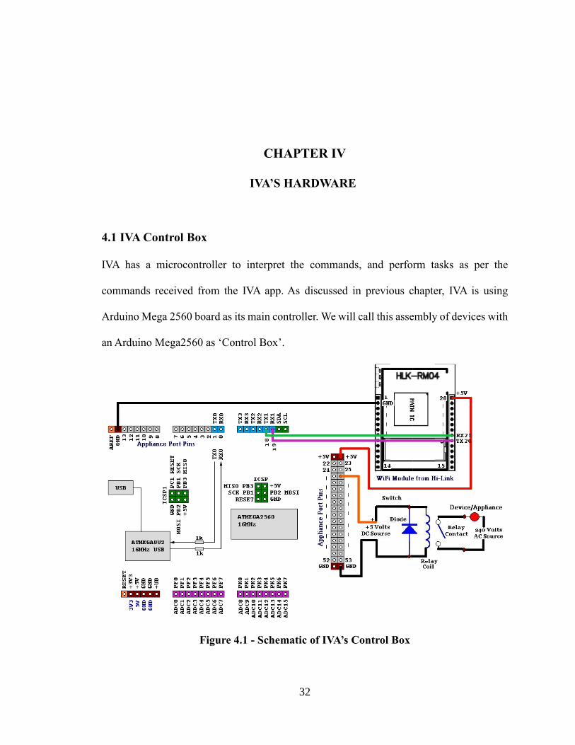
4.1 IVA Control Box ................................................................................................ 32
4.1.1 Control Box connections .............................................................................. 33
4.1.2 Explanation of schematics ........................................................................... 33
4.1.3 Power circuits ............................................................................................... 34
4.2 Wi-Fi connection and setup ............................................................................... 34
4.2.1 Step1: Physical connections ........................................................................ 36
4.2.2 Step2: Configuring parameters .................................................................... 37
4.2.2.1 If using Windows OS to configure Wi-Fi .......................................... 37
4.2.2.2 If using Apple Computer to configure Wi-Fi ..................................... 38
4.2.2.3 Android to check the Wi-Fi security type .......................................... 38
4.3 Receiving the command from the app ................................................................ 40
4.4 Command structure ........................................................................................... 41
4.5 Controlling actual devices ................................................................................. 43
4.6 ‘setup’ method code snippet for Control Box .................................................... 43
4.6.1 Explanation ................................................................................................... 44
viii
4.7 ‘loop’ method code snippet ................................................................................. 45
4.7.1 Explanation ................................................................................................. 49
4.7.2 Flowchart ..................................................................................................... 50
CHAPTER V
IVA’S SOFTWARE AND INTELLIGENCE …......................................................... 52
5.1 User Interface .................................................................................................... 52
5.1.1 XML code ..................................................................................................... 53
5.1.2 Explanation ................................................................................................... 55
5.2 Toggle Button .................................................................................................... 56
5.3 Activating microphone for voice commands .................................................... 57
5.4 How speech to text conversion works ............................................................... 61
5.4.1 Speech to text processing ............................................................................ 61
5.5 Socket connection and communication code ...................................................... 63
5.6 Filtering hot words code ..................................................................................... 64
CHAPTER VI
CONCLUSION AND FUTURE WORK …......................................................... 66
6.1 Conclusion .......................................................................................................... 66
6.2 Future Work ........................................................................................................ 66
6.2.1 Improving voice capturing ......................................................................... 67
6.2.2 Scalability for adding new devices ............................................................. 67
6.2.3 Improving IVA’s intelligence ...................................................................... 68
ix
References ................................................................................................................... 69
Appendices .................................................................................................................. 71
Appendix A ............................................................................................................ 71
Appendix B ............................................................................................................ 74
Appendix B.1 ................................................................................................... 74
Appendix B.2 ................................................................................................... 76
x
LIST OF TABLES
Table 2.1 – Comparision of Wi-Fi and ZigBee network technologies ............................. 11
Table 4.7 – Commands used by IVA................................................................................ 42
Table 5.1 – Hot Words...................................................................................................... 60
xi
LIST OF FIGURES
Figure 1.1 – Smartphone vs PC market shipment in millions ............................................ 1
Figure 2.1 – Speculated Nest Thermostat network architecture ...................................... 15
Figure 2.2 – Speculated Nest Thermostat network architecture ...................................... 17
Figure 2.3 – Amazon Echo connecting to Cloud Server speculated diagram .................. 22
Figure 2.4 – Image of Belkin Wemo switch ..................................................................... 23
Figure 2.5 – Belkin Wemo speculated connection architecture ....................................... 24
Figure 3.1 – Arduino Mega 2560 pinouts ......................................................................... 29
Figure 3.2 – Working of IVA on Wi-Fi technology ......................................................... 30
Figure 4.1 – Schematic of IVA’s Control Box ................................................................. 32
Figure 4.2 – Wi-Fi setup showing Hi-Link’s HLK-Rm04 chip ...................................... 35
Figure 4.3 – Configuring the Wi-Fi module ..................................................................... 36
Figure 4.4 – Windows Network configuration ................................................................. 37
Figure 4.5 – Mac OS Wi-Fi network preferences............................................................. 38
Figure 4.6 – Selecting Wi-Fi network on Android device ............................................... 39
Figure 4.7 – Loop method flowchart ................................................................................ 50
Figure 4.8 – Loop method flowchart continued. . . ......................................................... 51
Figure 5.1 – screenshot of IVA’s user interface ............................................................... 56
Figure 5.2 – Flowchart for toggle button (light) event listener ....................................... 57
Figure 5.3 – Screenshot of voice dialog box for speech-to-text ....................................... 58
xii
Figure 5.4 – Screenshot of response from speech to text ................................................ 59
Figure 5.5 – Overview of Speech-to Text processing and its visualization .................... 63
1
CHAPTER I
INTRODUCTION
1.1 Smartphone reach and accessibility
As computers are becoming faster, smaller and cheaper, they are intercepting more aspects
of common life. Today, a smartphone's processing power is comparable to that of a much
larger desktop unit. Hand-held devices, such as smart phones and tablets are getting more
proficient in understanding environment via the sensors embedded in them. As reported by
various sources, including AVC [1], Forbes [22] and Business Inside [21], smart phones
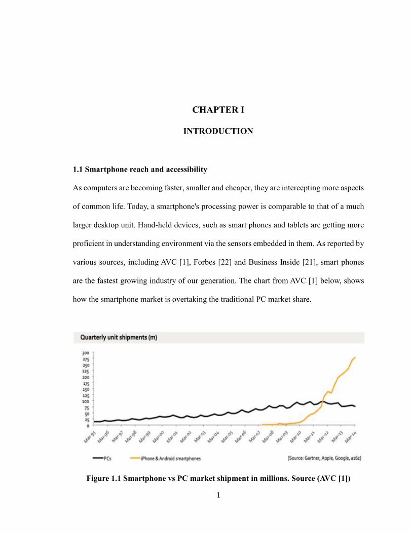
are the fastest growing industry of our generation. The chart from AVC [1] below, shows
how the smartphone market is overtaking the traditional PC market share.
Figure 1.1 Smartphone vs PC market shipment in millions. Source (AVC [1])
2
The chart in Figure 1.1 shows that the acceptance of portable computers, i.e. smartphones,
tablets and wearable computers is a massive world-wide phenomenon. The obvious
conclusion from the high diffusion of hand-held units is that the society is getting
comfortable with mobile technology.
Let us look back a decade or two; the technology then was much less advanced than it is
today. This was the time of personal computers. A study by Pew Research [4] shows that
older people have started accepting smartphone technology at a much faster rate than a few
years ago.
As reported by PewResearchCenter [4]: older people, mostly above 65 years of age had
difficulties in learning computers then. For them, computers were bulky, less useful, and
considered difficult to learn and operate, whereas nowadays, the elderly population in the
United States is getting more open to using smartphones than personal computers, as per
Axial Exchange’s article [8]. This is mainly a consequence of features such as portability.
Useful array of sensors embedded in the device such as GPS, camera, health-monitoring
elements, as well as voice recognition help users’ devices collect data. In addition,
smartphones provide a sense of continuous and transparent Internet connectivity, with all
the beneficial elements of information and services at the user's fingertips.
Notably, the Human Computer Interface (HCI) elements have become simpler with natural
hand gestures and touches, in comparison to mouse and keyboards as primary input
instruments for PCs. Consequently, smartphones act as facilitators, bringing information
3
and services, not only to the senior elements of society but to everybody, and they do it in
a much more intuitive way.
A research conducted by the Collat School of Business at the University of Alabama [5]
indicates that the number of smartphones in use will outnumber the total population on the
planet. The estimate given by Collat School of Business, states that there would be around
ten billion mobile Internet users, by the year 2016. The assumed world population is little
more than seven billion. This divides to approximately 1.4 mobile devices per person living
on face of earth.
As per these articles of Techcrunch [9] and The Telegraph [10], smartphones are reaching
developing countries at faster rate than their developed countries counter parts. The main
concern for the lower income group is the cost to connect with the technology. Thus, the
focus is now shifted to marketing less expensive phones with cheaper Internet connectivity
options. There is a plethora of small, mid-tier, and large telecom companies trying to
provide easier access with affordable hardware, and software solutions. The growth of
smartphone adoption in countries like Brazil, China, India, and Argentina is reported to be
exponential. This shows that smartphones are gaining wide ownership and reaching
consumers who were aloof from the allure of information-based technologies and services.
Innovation in the fields of Cloud Computing, Internet-Of-Things, and automation is
changing the face of technology of the twenty first century.
4
1.2 Internet-of-Things
As computers are getting more efficient in handling complex and large data using cloud
computing technology, it is becoming a common practice to introduce dedicated computers
to make traditional electro-domestic devices automated. For example: TVs, microwaves,
washing machines, dish washers, and even home based coffee brewing appliances are
getting 'smarter'.
The new generation of home appliances is being manufactured with the expectation of
making them transparently connected to the world of Internet, through dedicated
microcontrollers. The next 'big thing' in technology is prophesied to be different types of
smaller devices interacting as a single coordinated unit. This collection of small
heterogeneous devices working together is now called as ‘Internet of Things’ or IoT. It is
a new term used to describe the architectural model in which an unlimited, and ever
growing number of heterogeneous devices can be connected to the Internet. According to
proponents of model by Telecomengine [11], devices will get more connected from the
isolated world, than they are right now.
1.3 Home Automation
One of the most targeted areas for the IoT is Home Automation. Home Automation, also
called Domotic Computing, enables a user to control home devices using a remote control.
Although, home automation is not a new concept, the idea of making homes smarter is
gaining popularity as a by-product of the success and diffusion of the IoT notion. Currently,
a user can control home devices by a touch of a UI control in an app or a specific gesture
5
on their smartphones or tablet-type mobile devices.
1.4 Some background on Domotic Computing
Nikola Tesla first patented the technology of remote control, but the use of the technology
was not imagined until inception of twentieth century, when the use of electrical systems
became common.
The Idea of modern home automation was first demonstrated in the 1930s. The rough idea
of controlling electrical based home appliances was shown in World Fairs at that time in
Chicago and New York. Engineers gave this idea a serious thought in the late 1960s and in
early 1970s. In 1966, Jim Sutherland, an engineer working for Westinghouse Electric [6],
developed a home automation system called "ECHO IV"; this was a private project and
was never commercialized [2]. ECHO IV was way too ahead of its time for people to accept
such a technology in their daily lives. Moreover, the computing needed to make a complete
home automation lacked in the year 1966.
1.5 Current Status of Home Automation
Smart software embedded in powerful microcontrollers and processors has made it even
more feasible to design and develop cheap automation devices. Thus, home automation is
getting immensely popular. Software companies like Google, Amazon, Apple, Comcast,
AT&T, and many more have either stepped in, or are planning to get in the home
automation business. We will consider each company’s home automation product in detail
in next chapter. This shows that home automation is seen as one of the next frontier in
6
technology.
1.6 Home Automation popularity
Home controlling is not a concept of future. Controlling devices at home using a remote
control is not a new thing. We have televisions, air conditioners, music systems, and even
garage doors that are controlled via a dedicated remote control. Most of these physical
devices are now implemented as software apps running on smart phone, tablets and PCs.
So far, the idea of controlling homes with the use of a button-driven control unit has been
widely accepted by the world.
Now a day, the technology for making homes smart, malleable, fast, and responsive with
less errors and crashes is ready, and so are its consumers. The homes of today are getting
ready to being controlled by a single universal smart remote. They are getting smart enough
to automatically decide, how appliances are able to interact or how to adapt to their owner’s
requirements. There are already smart thermostats and sensors setup in modern homes,
which can learn and study their users' needs and preferences. It can then adapt to the new
habits, and changing routines of its users.
We are already able to see simple and cheap automation products around us; video phones,
automated doorbells, RFID, motion sensing, smart thermostats, and temperature controls.
The market for smart home is ready with demands and new budding ideas. Ideas such as
natural language voice inputs to smart homes are in huge demand.
7
1.7 IoT with home automation and voice commands
Imagine, where the smart home talks to the user when the user needs to be reminded. The
home would understand the users’ daily needs and takes care before the user gives any
command. For example, if the smart home reminds the user to take his office folder before
leaving to work. Another example, the smart home can open the garage door, when the user
is leaving through the front door. Yet another example can be considered as, the smart home
brews the coffee as soon as user is getting ready in the morning. Imagine if the smart home
can do all of the above stuff without asking user for it.
The above can be achieved via IoT integration in home automation system. IoT becomes
really important in understanding the environments and interacting with its dedicated
network. IoT can connect heterogeneous devices like washing machines, refrigerators,
televisions, AC/heaters, motion detectors, garage doors, and many other types of devices
to collect data and issue command to perform tasks.
There was a television show named Eureka, which showed a smart home named SARAH.
SARAH was close to an intelligent human being, with her personal female voice,
personality and even ability to understand humor and sarcasm. The future is not far when
such smart homes could be seen. The digital assistants like Siri, Google Now are already
popular and interact with the users intelligently.
8
CHAPTER II
LITERATURE REVIEW
2.1 Present and future of home automation
The basic automation systems have become a large part of people’s lives today. Systems
such as motion sensing, intelligent thermostat control, adaptable luminescence, RFID,
biometrics, IR technology, RF technology, and CCTV security have become very common.
Advanced automation technology such as user recognition using facial features, voice
controlled commands, assisting in planning, and advising in daily life chores is already
implemented. The popularity of residential automation is growing quickly. According to
ABI Research [19], 1.5 million home automation systems were installed in the US in 2012,
and a sharp uptake could see shipments topping over 8 million in 2017. Cisco CEO John
Chambers predicts that the market will be worth $19 trillion by 2020[4].
In the year 2014, Google bought a company named Nest Labs for $3.2 billion (£2bn) [3].
California-based Nest Labs makes 'smart' home appliances [4]. Nest was founded by Tony
Fadell, the so-called "godfather of the iPod", after he left the position of head of music at
Apple in 2008[4]. Although Nest has many research oriented devices, Nest Labs currently
has just two products in market: the smart smoke alarm and smart thermostat. Nest is
planning to make home appliances smarter by giving them unique features such as washing
9
machine that will text its status, the refrigerator that can call, etc. It remains unseen, how
many features users want in their home appliances.
Today, we have a lot of cheap and costly home automation products in the market. Each
has a way to communicate to the device controllers. For example, the RF based remotes
can turn lights on and off, a smart plug that can be controlled via a smart phone or a tablet,
which can later be used to control specific devices. Motion detection has been around, since
the 1970's. Opening of the door, as soon as someone walks in front of it is a great example
of automation. These are a few common examples among a vast majority of diverse, and
most importantly, intelligent systems.
Most of the world’s top technology companies have been working on developing their own
version of home automation technology. The research has been ongoing for a couple of
years now. Many of them have either come up with their version of the technology for the
general public to buy, or they have their initial prototypes, ready to be launched soon.
We will try to understand the technologies of some of the most accomplished in the market.
As mentioned in the abstract section, the standards, hardware architecture, software
models, and protocols of most of the companies are hidden; thus, we will try to speculate
the details as to how they were able to implement their respective smart home technologies.
Each company has its own unique designs and implementations. None of the designs are
public. The companies developing technologies also collaborate with other manufacturers
so that the third party manufacturers can develop devices compatible with their platform.
For example, Phillips’s Hue bulb which changes its color can now be controlled via Apple’s
10
Home Kit, and Siri commands. To do this, Phillips had to collaborate with Apple to use
Apple’s platform and communicate with its devices.
2.2 Technology standards
The most commonly used standards and protocols are discussed in this section. Although,
most of the companies implement their own version of standards, it is difficult to analyze
each and every product’s unique platform. Thus, we would look into the comparisons of
open source and general defined standards.
In today’s time, there are a multitude of standards and protocols implemented by industries.
Each company is trying to implement their own technology into the market. Internet of
Things, or IoT is the communication platform for light-weight microcontroller based
devices. Each company and organization has its own unique way of implementing IoT
based solutions. Some have their ZigBee based routers needed to communicate with their
in-house manufactured devices, whereas some companies use Wi-Fi as its base wireless
network. Bluetooth is also widely used for designing IoT based networks.
Some examples of the home automation system are Apple’s home kit, Samsung’s
SmartThings platform, and AT&T’s home automation solutions. Comcast also has its own
home automation system. Each has their own devices talking to each other.
Thus, standardization is very fragmented in current times, which include Wi-Fi, ZigBee,
11
Bluetooth, Infrared or other wireless techniques to form a dedicated small network of
Internet of Things.
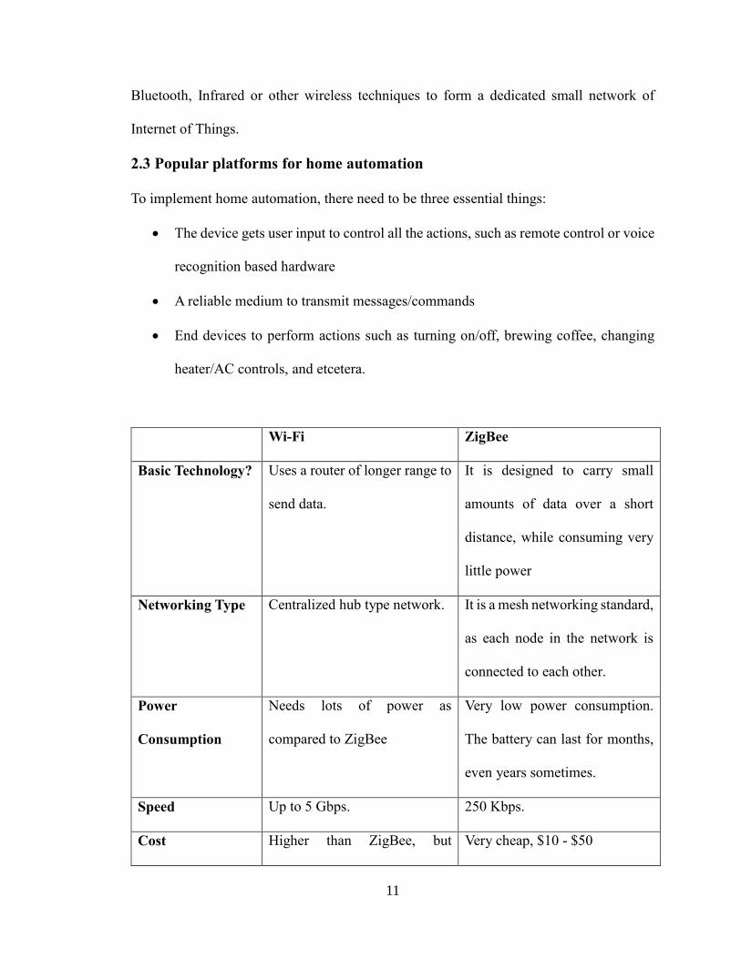
2.3 Popular platforms for home automation
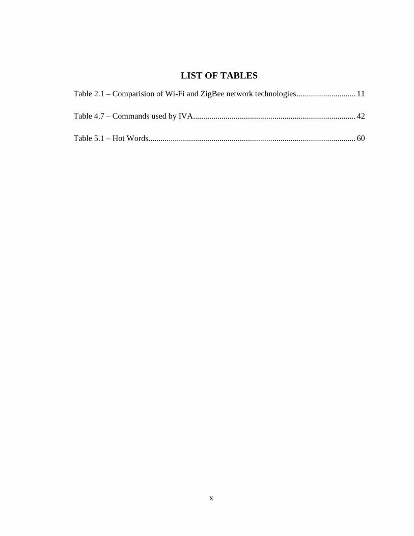
To implement home automation, there need to be three essential things:
The device gets user input to control all the actions, such as remote control or voice
recognition based hardware
A reliable medium to transmit messages/commands
End devices to perform actions such as turning on/off, brewing coffee, changing
heater/AC controls, and etcetera.
Wi-Fi ZigBee
Basic Technology? Uses a router of longer range to
send data.
It is designed to carry small
amounts of data over a short
distance, while consuming very
little power
Networking Type Centralized hub type network. It is a mesh networking standard,
as each node in the network is
connected to each other.
Power
Consumption
Needs lots of power as
compared to ZigBee
Very low power consumption.
The battery can last for months,
even years sometimes.
Speed Up to 5 Gbps. 250 Kbps.
Cost Higher than ZigBee, but Very cheap, $10 - $50
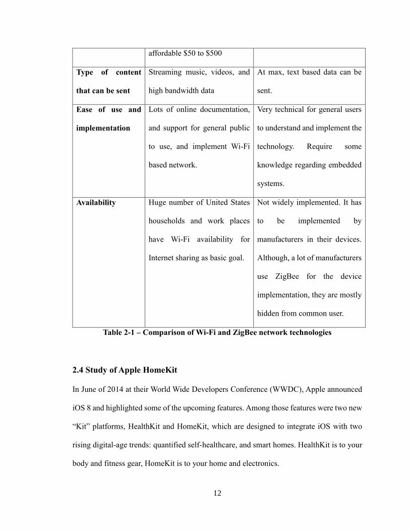
12
affordable $50 to $500
Type of content
that can be sent
Streaming music, videos, and
high bandwidth data
At max, text based data can be
sent.
Ease of use and
implementation
Lots of online documentation,
and support for general public
to use, and implement Wi-Fi
based network.
Very technical for general users
to understand and implement the
technology. Require some
knowledge regarding embedded
systems.
Availability Huge number of United States
households and work places
have Wi-Fi availability for
Internet sharing as basic goal.
Not widely implemented. It has
to be implemented by
manufacturers in their devices.
Although, a lot of manufacturers
use ZigBee for the device
implementation, they are mostly
hidden from common user.
Table 2-1 – Comparison of Wi-Fi and ZigBee network technologies
2.4 Study of Apple HomeKit
In June of 2014 at their World Wide Developers Conference (WWDC), Apple announced
iOS 8 and highlighted some of the upcoming features. Among those features were two new
“Kit” platforms, HealthKit and HomeKit, which are designed to integrate iOS with two
rising digital-age trends: quantified self-healthcare, and smart homes. HealthKit is to your
body and fitness gear, HomeKit is to your home and electronics.
13
HomeKit is not a single control application. It is instead a hardware certification platform,
and database system that allows developers to create hardware. Moreover, it helps to
integrate the hardware with iOS to provide for easy discovery, configuration, management,
and communication between a wide variety of smart home products such as locks, lights,
security equipment, and other home automation products.
Armed with HomeKit products and your iOS device, one can set up their home such that
the lights turn on a specific time to wake one up. Furthermore, the thermostat could crank
the AC up when one will be driving home on a hot day. Additionally, at the end of the day,
one can snuggle into bed and talk out loud to their iOS device and tell HomeKit to shut the
house down for the evening.
2.4.1 HomeKit manufacturer certification criteria
1. HomeKit products have to meet two criteria in order to be compatible with the
HomeKit platform. First, they need to be certified through Apple’s MFi (Made For
iPhone/iPad) Program, a certification process Apple has had in place for years
(reaching back in some form or another all the way to the original “Made for iPod”
certification circa 2005). This certification is designed to ensure that any product
labeled works properly with Apple hardware, iOS, and that developers have said
that hardware needs to adhere to specific rules and security practices.
14
2. HomeKit platform must include a custom encryption co-processor in all HomeKit
certified hardware.
2.4.2 HomeKit working
HomeKit serves as the underpinning of your Apple-driven smart home experience. There
is no central HomeKit control panel. For example, on your iOS device that you can just
open up and control all your devices, HomeKit is always present in the background
handling everything. The actual interaction comes in four forms: through the
manufacturer’s application, through a third-party application created by an iOS developer,
through Siri voice control, and via digital and physical triggers.
2.4.2.1 Manufacturer Apps
Every application for a HomeKit-certified device typically contains two HomeKit related
elements. First, the application will have some ability to link your HomeKit-certified
hardware to a scene, room, or a zone. For example, your smart bulb system might have a
“scene” system where you can create scenes like “relaxation”, “movie time”, or “morning
routine”.
15
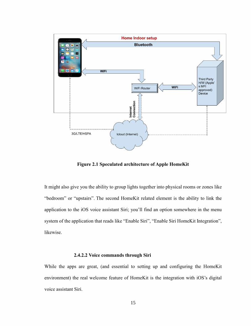
Figure 2.1 Speculated architecture of Apple HomeKit
It might also give you the ability to group lights together into physical rooms or zones like
“bedroom” or “upstairs”. The second HomeKit related element is the ability to link the
application to the iOS voice assistant Siri; you’ll find an option somewhere in the menu
system of the application that reads like “Enable Siri”, “Enable Siri HomeKit Integration”,
likewise.
2.4.2.2 Voice commands through Siri
While the apps are great, (and essential to setting up and configuring the HomeKit
environment) the real welcome feature of HomeKit is the integration with iOS’s digital
voice assistant Siri.
16
Due to heavy Siri integration, HomeKit system can now be controlled with nothing more
than the dedicated iOS device and user voice. There are online guides on how to add the
Philips Hue system with the HomeKit.
Siri’s control is pretty flexible, and if there is a scene/room/zone and a matching task Siri
can complete within the HomeKit database, she is pretty good about following natural
language patterns to fulfill the commands. Commands such as “Turn off the office lights”,
“Set the house to 75 degrees”, or “set morning scene” are all easily understood by Siri, if
your product’s HomeKit hardware/app supports it. There are various third party
manufacturers developing for HomeKit platform. Products such as coffee machines,
colorful lights with brightness control, smart thermostats, video door bells, automatic
garage doors, and alarm clocks are already available to common users for purchase.
2.5 Google’s Nest Thermostat
The Nest Learning Thermostat goes beyond just simple temperature detection in order to
make a real impact in user’s HVAC energy consumption. In this section, we will see what
Nest can do, how it does, what it does, who is behind it, and what challenges it faces in
the HVAC industry.
2.5.1 Current thermostat working
To understand Nest's value, let's first look at what other thermostats do. All thermostats let
you set a desired temperature, and monitor the current temperature.
17
Many thermostats rely entirely on the user to set the temperature. Though in recent years,
manufacturers have offered programmable thermostats that can help save energy. This
helps the user program certain temperatures for certain times of the day. For instance,
letting them automatically lower the temperature when they will be out of the house (to
save energy). However, due to the complexity of these thermostats, people do not always
program them correctly, which can negate most, if not all, of their energy-saving potential.
2.5.2 Nest smart approach
The Nest Learning Thermostat aims to solve this problem. Nest actually programs itself by
learning its user’s behavior patterns and desired temperatures for certain days and times
during the week, and then builds a schedule for their HVAC. It is not the only smart
thermostat in the market, but Google's purchase of Nest Labs for a reported $3.2 billion in
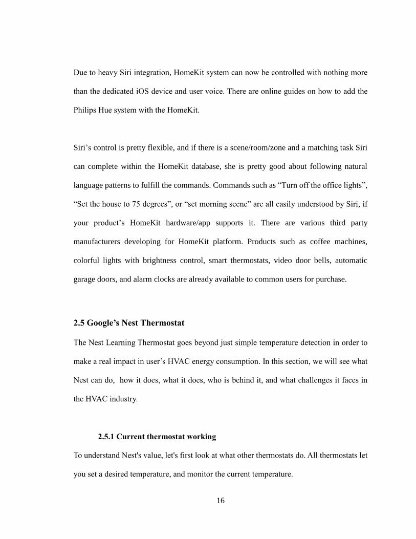
January 2014, has made it the most famous.
Figure 2.2 – Speculated Nest Thermostat Network Architecture
18
2.5.3 Nest features designed to appeal to consumers
Nest uses various inputs to observe day-to-day routine of its user and uses them to
maintain an HVAC schedule automatically, based on what it learns. (The company
calls this Nest Sense technology.)
Nest creates an auto-away mode based on what it has learned. This sets a
temperature for minimal HVAC activity, when the user is not in the building. The
“set away” mode can also be manually set, if the user wishes.
While it is actively heating or cooling, Nest displays an estimated time for the
system to reach the desired temperature.
Nest displays a green leaf any time the thermostat is running at energy-saving
settings. This can help teach users to make energy-saving decisions. For example,
if Nest has learned that they typically run the AC until the house is 74 degrees
Fahrenheit (23.3 Celsius), they could turn up the temperature until you see the green
leaf to save energy. The leaf will always appear at cooling settings of 84 degrees
Fahrenheit (28.9 Celsius) or higher, and heating settings of 62 degrees Fahrenheit
(16.7 Celsius) or lower, but its threshold will change based on its user’s habits.
Nest lets the user know what activity (between auto-away, user’s own adjustments
and the weather) results in the greatest energy savings throughout the day.
Nest uses Wi-Fi to connect to the user account at nest.com. This feature allows
them to monitor and adjust the Nest remotely from the Web site.
19
Nest supports a mobile app available for Apple iOS (iPod Touch, iPhone and
iPad) and Android devices. The app turns the mobile device into a remote
control for your Nest.
Nest can be added to any number of thermostats in a multi-thermostat building.
They will work alongside other thermostats, but note that each of Nest's energy-
saving features only apply to the rooms in its sensor range, and to the HVAC
components it controls.
A Nest account can manage up to 10 Nest devices, whether they are in the same
building or at multiple locations.
2.6 IFTTT (IF-THIS-THEN-THAT)
IFTTT also pronounced “lift” without ‘L’, is a very novel approach of controlling multiple
devices by a trigger. IFTTT has a website which encourages users to design their own
triggers, actions and conditions to make compatible devices perform tasks. IFTTT calls
these scripts with triggers recipes.
For example, if a user just makes a recipe that the sensor inside his/her liquor
cabinet detects that a bottle is fetched, then the system would tweet a celebratory
message.
If one owns the Philips Hue smart lighting system, for instance, the user could use
IFTTT to automatically turn on a light every time they are tagged in a Facebook
photo.
20
In one more example, the user could use IFTTT to automatically email readers
when they comment on your WordPress blog. There are numerous combinations
(called recipes) on IFTTT that can make life easier.
IFTTT is not a home automation platform; it is more general platform to perform a task if
a trigger is met. It can simply send a notification on a smartphone if the weather gets bad.
In this example, there is no home automation used. Although, IFTTT is expanding to
work with many home automation sensors and devices.
2.7 Amazon Echo
Amazon is another player in the market with their unique smart home device, named
Amazon Echo. Amazon has been developing a comprehensive home automation product
to help user order items from their website with just their voice. The device they were
developing had to be intelligent enough to understand what the user needs just by natural
language voice processing.
The Amazon development team had an idea that if they can connect Echo with home
automation in a way that the device’s natural language processing can be used for more
than just order.
They came up with a minimalistic, yet intuitive design of a cylindrical speaker. The device
is just a speaker with 7 noise canceling microphones. The device can respond to any user’s
voice commands and their natural speech. Amazon’s Echo device responds to a wake-up
21
command. The command is ‘Alexa’ or ‘Amazon’ or ‘Echo’ as per the user sets the
command. The Echo has multi-colored lights that indicates the user that it is listening. It
lights up, when the wakes up and when command is spoken by the user.
2.7.1 Speculating working of Amazon Echo
Let’s speculate. It needs a Wi-Fi connection to connect to the home Internet, thus all the
natural language processing and understanding should be done on the cloud. Echo has a
female voice to talk back to the user. The sound can be heard from the speaker of the device.
Echo can also play the user’s favorite music. To do this, it has to have an access of the
user’s account along with the access of the cloud.
To setup Amazon Echo, an app is required to connect with the device’s own Wi-Fi channel
to provide login information, and preferences. Once the device is set, it keeps the track of
the user’s demands and learns about their requirements, and behavior.
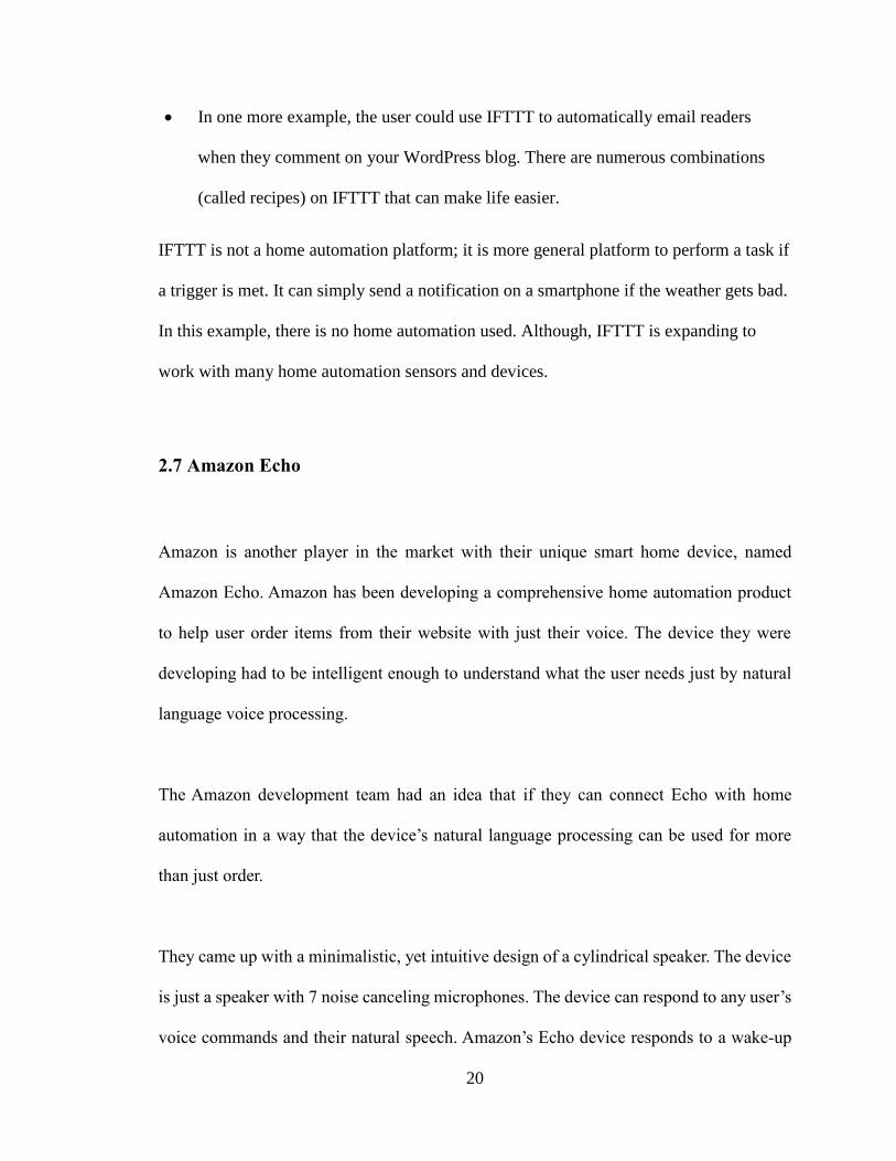
2.7.2 Speculated Architecture of Amazon Echo
Amazon Echo seems to have similar architecture to that of Google’s Nest thermostat.
However, it can do much more than just learn about the temperature preferences. Echo is
a dedicated device which can be connected to the Internet using user’s already setup home
Wi-Fi network. The more detailed diagram can be shown in the diagram below.
The Amazon Cloud Server is a collection of different services such as voice processing
server, searching for user requirements, login services, and many more.
22
Figure 2.3 - Amazon Echo connecting to Cloud Server speculated diagram
2.8 Belkin’s Wemo Switch
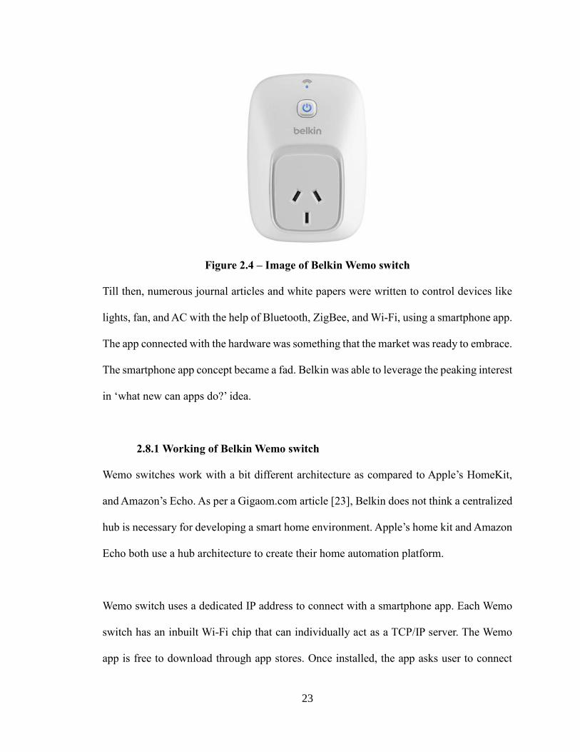
Belkin already had a name in networking devices, power, and cable accessories. Belkin
came out with Wi-Fi based switch before companies like Apple, Google and Amazon came
into the home automation business. The Wemo switches were launched in 2012. Back then,
the Wemo switches were controlled with iPhone/iPod/iPad app. In January 2013, Belkin
announced the support for Android OS. They also demoed their other home automation
products line. New products such as smart motion sensors, IP cameras were displayed in
Consumer Electronics Show (CES) 2013. They made huge interest regarding the capability
of smartphones controlling home devices.
23
Figure 2.4 – Image of Belkin Wemo switch
Till then, numerous journal articles and white papers were written to control devices like
lights, fan, and AC with the help of Bluetooth, ZigBee, and Wi-Fi, using a smartphone app.
The app connected with the hardware was something that the market was ready to embrace.
The smartphone app concept became a fad. Belkin was able to leverage the peaking interest
in ‘what new can apps do?’ idea.
2.8.1 Working of Belkin Wemo switch
Wemo switches work with a bit different architecture as compared to Apple’s HomeKit,
and Amazon’s Echo. As per a Gigaom.com article [23], Belkin does not think a centralized
hub is necessary for developing a smart home environment. Apple’s home kit and Amazon
Echo both use a hub architecture to create their home automation platform.
Wemo switch uses a dedicated IP address to connect with a smartphone app. Each Wemo
switch has an inbuilt Wi-Fi chip that can individually act as a TCP/IP server. The Wemo
app is free to download through app stores. Once installed, the app asks user to connect
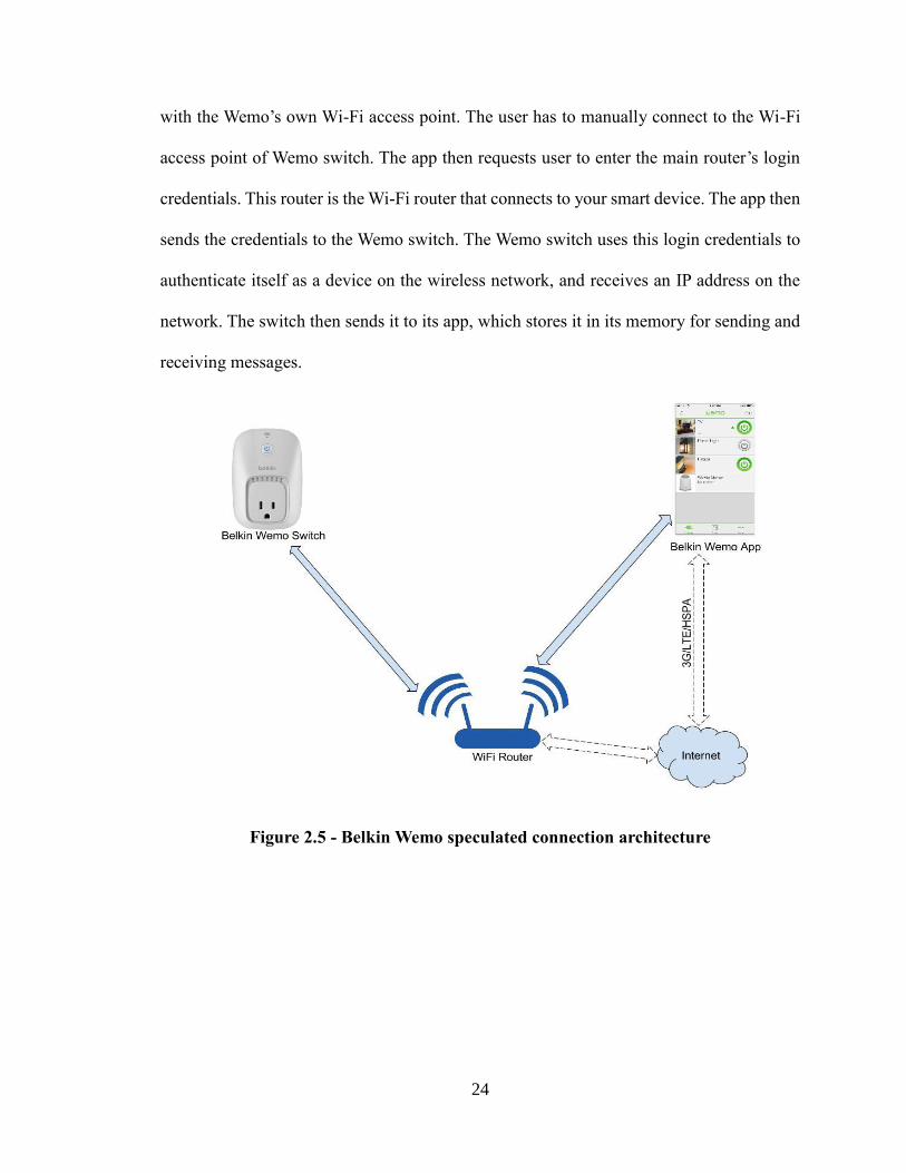
24
with the Wemo’s own Wi-Fi access point. The user has to manually connect to the Wi-Fi
access point of Wemo switch. The app then requests user to enter the main router’s login
credentials. This router is the Wi-Fi router that connects to your smart device. The app then
sends the credentials to the Wemo switch. The Wemo switch uses this login credentials to
authenticate itself as a device on the wireless network, and receives an IP address on the
network. The switch then sends it to its app, which stores it in its memory for sending and
receiving messages.
Figure 2.5 - Belkin Wemo speculated connection architecture
25
CHAPTER III
IVA SMART HOME
3.1 Introduction to IVA
Intelligent Voice Activated Home automation, or IVA for short, is my own independently
designed smart home automation architecture. IVA is designed to understand the user’s
natural language voice commands along with support for touch controls from an Android
device. IVA software can be installed on the Android device as an app. The Android device
should have basic Wi-Fi capability in order to connect with the hardware. Additionally, an
already setup Wireless Local Area Network (WLAN) is needed to make IVA communicate
with the specially designed hardware to control end devices.
This section of thesis also explores the reasons for which the specific technologies are
implemented for IVA’s smart home architecture. Here, we discuss the overall
implementation design and the reasons, which led to selection of specific technologies over
others. For instance: why Wi-Fi was selected over Bluetooth or ZigBee? Why hardware
was designed on Arduino platform? And why the intelligence was programmed as a
software on the Android app instead of implementing it on the hardware?
This thesis does not claim that we have designed a new way of communicating in home
automation. It shows the reasons why we selected Wi-Fi over Bluetooth and ZigBee.
26
3.2 Reasons for using Wi-Fi over ZigBee and X10
As explained above, IVA uses Wi-Fi as main communication medium. The reasons for
using Wi-Fi are:
3.2.1 Usage
Wi-Fi is a wide spread technology to connect heterogeneous type of computer devices. It
is the most common technology to connect a sufficient size network in LAN format, be it
desktop, laptop, smart phone, tablet or any other computer with Wi-Fi capability.
ZigBee and X10 are dedicated network which need special devices to create a network.
For example: ZigBee needs ZigBee controller (ZC), ZigBee Router and ZigBee enabled
device.
As for X10, it needs a special type of power line transmitter-receiver to send information
in analog mode to the devices.
3.2.2 Cost
Wi-Fi is a very cheap technology. If a computer does not have a Wireless card (capability
to connect to Wi-Fi network), there are various add-ons for as cheap as $10 to $100. Even
if there is no Wi-Fi Router, we can still create a hotspot network using a Laptop or a
smart phone, which can route the data.
In conclusion, most of the computers (small/large) have capabilities to connect to a Wi-Fi
network. But if a computer lacks hardware to connect to a Wi-Fi network, the add-on
27
hardware to connect to the Wi-Fi network is very cheap. Even a dedicated router is not
required to create a network as nowadays, the computer devices are powerful enough to
create a virtual Wi-Fi router as its own secured Network, working as a Hotspot.
3.2.3 Availability
This is the most important reason for selecting Wi-Fi over other type of home automation
protocols. Wi-Fi technology is the most common wireless technology used to connect to
heterogeneous computer hardware, running on heterogeneous software. For Example; a
Wi-Fi network can connect PCs, Mac, Linux based machines, Android devices all in one
network. The computers do not need any kind of special treating to access to the network,
provided they are rightly authenticated and authorized to use the network.
Wi-Fi technology is so common that most of the houses are equipped with it. Most of the
houses in United States have a Wi-Fi router which routes the Internet connection to local
devices on the network. Thus a special setup is not needed for a home automation system
to work. As the setup is already available.
3.2.4 Cloud Computing is easier with Wi-Fi
At present, cloud computing is huge. The controller device can be used to integrate
powerful cloud servers to control the home automation. Here the example is speech
synthesis. The IVA app can give natural language speech based commands to the
controller device, which in turn uses cloud services to convert spoken commands to text
and then the app takes a decision by understanding what user's requirements.
28
3.3 Limitations of Wi-Fi over ZigBee and X10
The most observable limitation of Wi-Fi over ZigBee and X10 is that the Wi-Fi has much
shorter range than ZigBee or X10. Although, a router is sufficient enough for most of the
common home sizes in United States, we can easily improve the range of the Wi-Fi
network by using an 'Access Point' or a Repeater to increase the range of the network.
Here, ZigBee is very efficient in increasing the range as each ZigBee device itself acts as
a range extender. As for X10, as it uses the basic power lines, (the home AC power
wiring) the analog signals travel much farther, when a range is considered. But for X10, a
special wireless remote control and the receiver is needed to connect to the network.
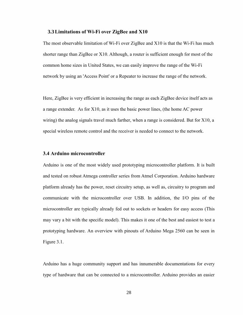
3.4 Arduino microcontroller
Arduino is one of the most widely used prototyping microcontroller platform. It is built
and tested on robust Atmega controller series from Atmel Corporation. Arduino hardware
platform already has the power, reset circuitry setup, as well as, circuitry to program and
communicate with the microcontroller over USB. In addition, the I/O pins of the
microcontroller are typically already fed out to sockets or headers for easy access (This
may vary a bit with the specific model). This makes it one of the best and easiest to test a
prototyping hardware. An overview with pinouts of Arduino Mega 2560 can be seen in
Figure 3.1.
Arduino has a huge community support and has innumerable documentations for every
type of hardware that can be connected to a microcontroller. Arduino provides an easier
29
programming platform in comparison to core microcontroller programming, where the
users have very predefined set of functions and pin names. It becomes much easier for
naïve programmers to program for the Arduino boards. In addition, Arduino board, which
needs +5V to work, can just be powered by the computer’s USB port.
Figure 3.1 Arduino Mega 2560 pinouts
Arduino boards comes in various sizes for flexible usability. A vary basic version of
Arduino is Uno board with bare minimum ports and pins to support hardware connected to
it. If the user needs more powerful microcontroller with more pins and ports, Arduino Mega
can be handy. Also, the code is portable across different type of Arduino boards. Thus, code
written for Arduino Uno can be easily ported to Arduino Mega with no changes.
Arduino are really cheap, and they are easily available all over the world. Arduino Uno
board can be purchased for as less as $10 in the United States. It comes with an inclusion
30
of the USB cable in order to connect with the computer. The Arduino IDE, which is used
to program and upload the machine code to the hardware is also free to download. The
Arduino software is easy-to-use for beginners, yet flexible enough for advanced users. It
runs on Mac, Windows, and Linux.
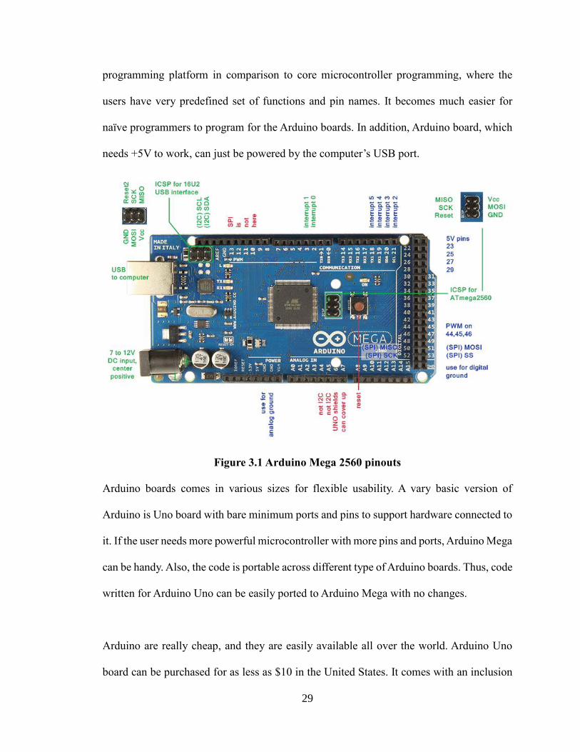
3.5 IVA’s components
Figure 3.2 – working of IVA on Wi-Fi technology
IVA’s architecture is broken down in three main categories, which we would discuss the
design details in next chapters:
1. The hardware has its capability to connect to the router. It would also be able to
turn on/off specified devices, such as lights and fans. Let’s call it ‘Control Box’.
2. GUI for users and app software programming that provides user aesthetics.
3. Our own natural language interpreter to understand user commands, which are
transformed from voice to text.
IVA’s
Control Box
Setup
31
We are calling the whole hardware setup as ‘Control Box’. There can be a number of
Control Boxes in one house. They would work in symbiosis, and would be controlled with
the help of a single app. Each Control Box would have its own unique IP address on the
WLAN formed by a router. These IP addresses would be used to send and receive messages
from IVA app on an Android device. The above Figure 3.2 shows one such Control Box.
We will understand the working of it in more details in next chapter.
32
CHAPTER IV
IVA’S HARDWARE
4.1 IVA Control Box
IVA has a microcontroller to interpret the commands, and perform tasks as per the
commands received from the IVA app. As discussed in previous chapter, IVA is using
Arduino Mega 2560 board as its main controller. We will call this assembly of devices with
an Arduino Mega2560 as ‘Control Box’.
Figure 4.1 - Schematic of IVA’s Control Box
33
4.1.1 Control Box connections:
1. Power setup: Arduino uses 5V as power supply. A 1 Amp current supply is more
than enough to make our hardware work. Although, the power consumption
widely depends on the amount of devices connected on the ports and using
pullups to power the pins.
2. A relay switch, which would be controlled by I/O pins of the board. Here, in the
schematics, pin 27 is seen controlling the relay switch.
3. A UART port uses receiving (RX) pin and transmitting (TX) pin for
communication. We have connected a Wi-Fi chip named HLK-Rm04 for
providing wireless communication feature to IVA. We will see the setup of HLK-
Rm04 in details further in this chapter.
4.1.2 Explanation of schematics
In the Figure 4.1 above, the Arduino Mega 2560 board pinouts is shown. On the board,
the pin numbers 0, 1, 14, 15, 16, 17, 18, 19 are all Universal Asynchronous Receiver
Transmitter (UART) communication port pins. We would use one of the pair 18 (TX1)
and 19 (RX1) to connect to a Wi-Fi module. The Wi-Fi module HLK-Rm04 that would
be used is developed by a company HI-LINK Co. Ltd [14]. All the other unmarked pins
are basically 5V internally pulled up I/O pins. That is, the pins to connect a 5V digital
sensors or other digital devices. The pins here, would be used to control end appliances.
Thus, the I/O pins will be connected to the end devices controller switches using a relay
or a voltage regulator.
34
A relay switch will be used to control on/off of the devices. A relay is basically an
electromechanical switch. It is generally used to command a high voltage device like
lights, fan, etc., with a comparative small voltage like microcontroller I/O pin. The
controller I/O pin mostly has 5V output voltage.
4.1.3 Power circuit
In Figure 4.1, the power jack is labeled. A 5V DC connection will power the Arduino board.
The Arduino board will then power the HLK-RM04 Wi-Fi chip by connecting to the VCC
and GND pins. Any of the three +5V pins can be connected to Rm04 chip’s pin number 28.
Similarly, a ground (GND) pin from Arduino board should be connected to Wi-Fi module’s
pin number 2. This will take care of powering the Arduino board, which in turn will power
the Wi-Fi chip.
4.2 Wi-Fi connection and setup
The HLK-Rm04 Wi-Fi module's pins 20 and 21 are connected to Arduino Mega's pins 18
and 19 for transmitting (TX) and receiving (RX) respectively. The TX pin of Wi-Fi module
is connected to RX pin of the Arduino, so that the transmitting line is connected to receiving
line of opposite circuit and vice-versa.
The Wi-Fi module has to be setup in such a way that it can connect with an already available
wireless network. There can be more than one Control Box with the setup. Each Control
Box needs one Wi-Fi module in order to identify the box in the network. Moreover, this
increases IVA’s access to other hardware in other rooms.
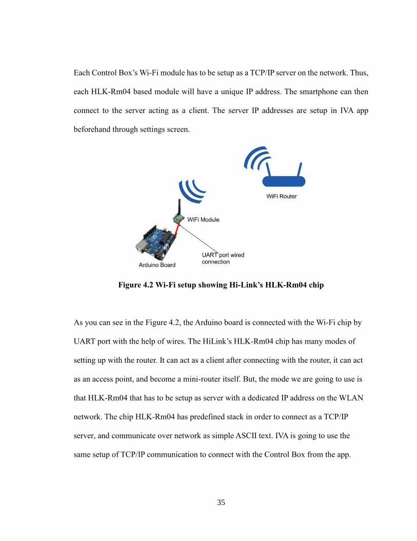
35
Each Control Box’s Wi-Fi module has to be setup as a TCP/IP server on the network. Thus,
each HLK-Rm04 based module will have a unique IP address. The smartphone can then
connect to the server acting as a client. The server IP addresses are setup in IVA app
beforehand through settings screen.
Figure 4.2 Wi-Fi setup showing Hi-Link’s HLK-Rm04 chip
As you can see in the Figure 4.2, the Arduino board is connected with the Wi-Fi chip by
UART port with the help of wires. The HiLink’s HLK-Rm04 chip has many modes of
setting up with the router. It can act as a client after connecting with the router, it can act
as an access point, and become a mini-router itself. But, the mode we are going to use is
that HLK-Rm04 that has to be setup as server with a dedicated IP address on the WLAN
network. The chip HLK-Rm04 has predefined stack in order to connect as a TCP/IP
server, and communicate over network as simple ASCII text. IVA is going to use the
same setup of TCP/IP communication to connect with the Control Box from the app.
36
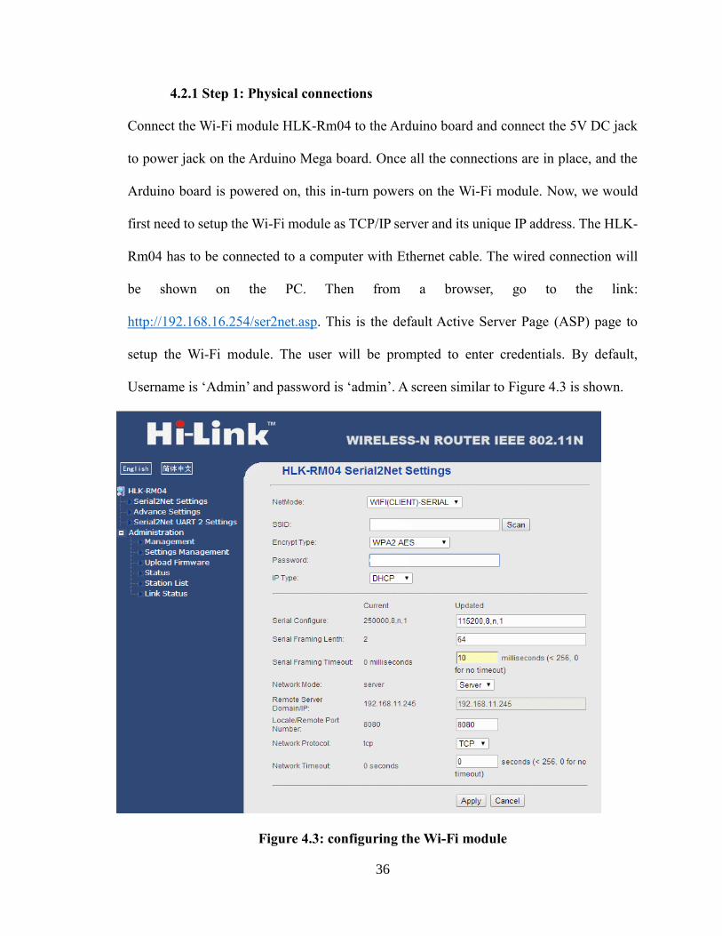
4.2.1 Step 1: Physical connections
Connect the Wi-Fi module HLK-Rm04 to the Arduino board and connect the 5V DC jack
to power jack on the Arduino Mega board. Once all the connections are in place, and the
Arduino board is powered on, this in-turn powers on the Wi-Fi module. Now, we would
first need to setup the Wi-Fi module as TCP/IP server and its unique IP address. The HLK-
Rm04 has to be connected to a computer with Ethernet cable. The wired connection will
be shown on the PC. Then from a browser, go to the link:
http://192.168.16.254/ser2net.asp. This is the default Active Server Page (ASP) page to
setup the Wi-Fi module. The user will be prompted to enter credentials. By default,
Username is ‘Admin’ and password is ‘admin’. A screen similar to Figure 4.3 is shown.
Figure 4.3: configuring the Wi-Fi module
37
4.2.2 Step2: Configuring parameters
NetMode: Select NetMode as ‘WIFI(SERVER)-SERIAL’. This will make the Wi-Fi
module as a server, which would be accessed using its own dedicated IP address.
SSID:
The SSID is the name of the Wi-Fi network which is going to be the routing network. In
short, the WLAN is the name of the home network, the smart phone device is connected.
Encryption Type:
Encryption type depends on the router or the switch. To find out the encryption type of
your network, the computer should first be connected to the WLAN.
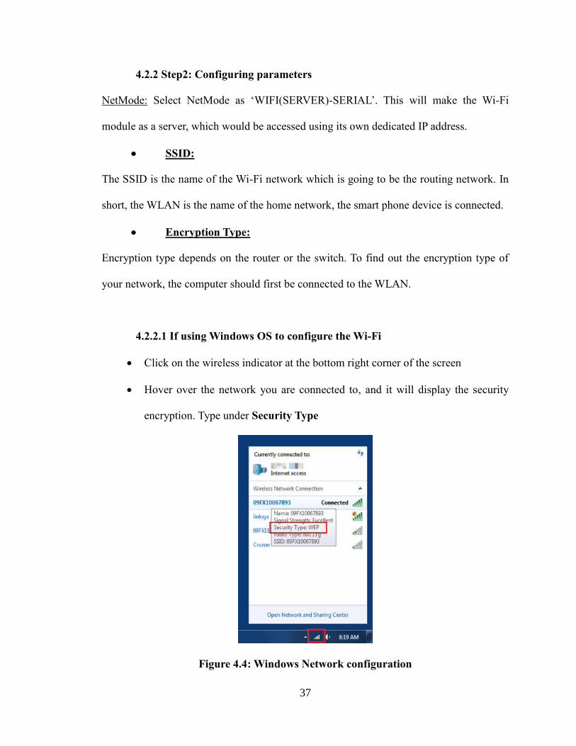
4.2.2.1 If using Windows OS to configure the Wi-Fi
Click on the wireless indicator at the bottom right corner of the screen
Hover over the network you are connected to, and it will display the security
encryption. Type under Security Type
Figure 4.4: Windows Network configuration
38
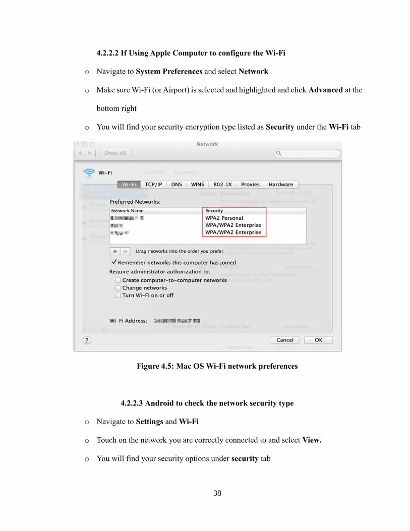
4.2.2.2 If Using Apple Computer to configure the Wi-Fi
o Navigate to System Preferences and select Network
o Make sure Wi-Fi (or Airport) is selected and highlighted and click Advanced at the
bottom right
o You will find your security encryption type listed as Security under the Wi-Fi tab
Figure 4.5: Mac OS Wi-Fi network preferences
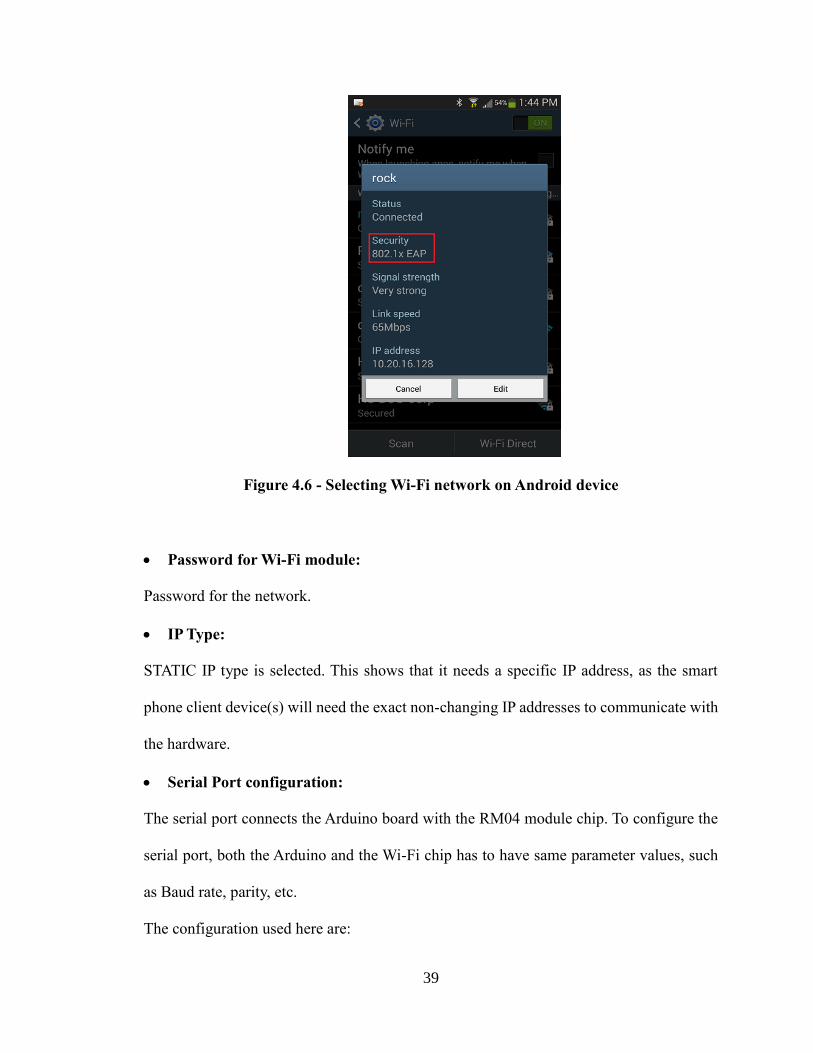
4.2.2.3 Android to check the network security type
o Navigate to Settings and Wi-Fi
o Touch on the network you are correctly connected to and select View.
o You will find your security options under security tab
39
Figure 4.6 - Selecting Wi-Fi network on Android device
Password for Wi-Fi module:
Password for the network.
IP Type:
STATIC IP type is selected. This shows that it needs a specific IP address, as the smart
phone client device(s) will need the exact non-changing IP addresses to communicate with
the hardware.
Serial Port configuration:
The serial port connects the Arduino board with the RM04 module chip. To configure the
serial port, both the Arduino and the Wi-Fi chip has to have same parameter values, such
as Baud rate, parity, etc.
The configuration used here are:
40
o Serial configure = 9600,8,n,1
o Serial Framing Length = 64
o Serial Framing Timeout = 10
Network Mode:
Network is selected as Server. This is the TCP/IP mode. Here, it is shown that the Wi-Fi
chip will act as TCP/IP server when connected to the network.
Port:
The port number by default is kept unchanged. It is 8080.
Now that the Wi-Fi module HLK-Rm04 is connected to the network, the IVA app on an
Android device can now send commands to respective Control Box. Android app will act
as a client and open a connection stream with the server. The Wi-Fi module, which is now
setup as a server on the network will accept the connection, and then receive a command
from the app. The command is then interpreted, i.e. broken down into various fields to
understand what it is supposed to do.
4.3 Receiving the command from the app
The Control Box receives the command in the form of text on its UART port. This is a
serial port that connects the HLK-Rm04 Wi-Fi module to the Arduino controller board.
The port connections can be seen in the schematic image 4.1.
The program on Arduino controller is continuously polling for data on the UART port.
Thus, if the data is available, it would then check the command it has received. To activate
41
the UART port on Arduino, the following code is used: Serial1.begin(9600);
The polling code is shown below:
while (!Serial1) {
; // wait for serial port to connect. Needed for native USB
}
4.4 Command structure
A command is made up of eleven characters. Most of the characters are numeric in nature.
Let us break the commands into its bare bone pieces.
i. First, the command is encapsulated with start and stop characters. Any
command has to start with an asterisk (*) character, and end with a hash
character (#). All the characters except the start (*) and stop (#) characters
are numeric in nature.
ii. The * is followed by four numeric characters of unique home identification
number. These four digit characters are unique to a home. This is done so
that only the authentic Android device can control the hardware. For
example, ‘*1234XXXXX#’. Here, the home identification number is 1234.
All the ‘X’ characters are next part of the command.
iii. The sixth and seventh digit identifies the room number. Thus, IVA can
support up to 99 unique rooms for a home. For example, the command till
room identification number would be: ‘*123401XXX#’. Here, the room
number 01 is addressed.
iv. Next two numbers are device identification number. These two digit number
42
will make the microcontroller decide which device to control. For example,
the command would be ‘*12340102X#’. The command shows that the
unique home number is 1234, the room number is 01 and the device that
has to be controlled is 02.
v. The second last character, i.e. the character before the stop character (#) is
the device control information. Here, the microcontroller is programmed
with switch-case statements to perform the actions to the device. For
example, if the device code to turn on is 1 then the entire command from
the Android app would be ‘*123401021#’. This means, that the home
number 1234, room 01, device 02 has to be switched on.
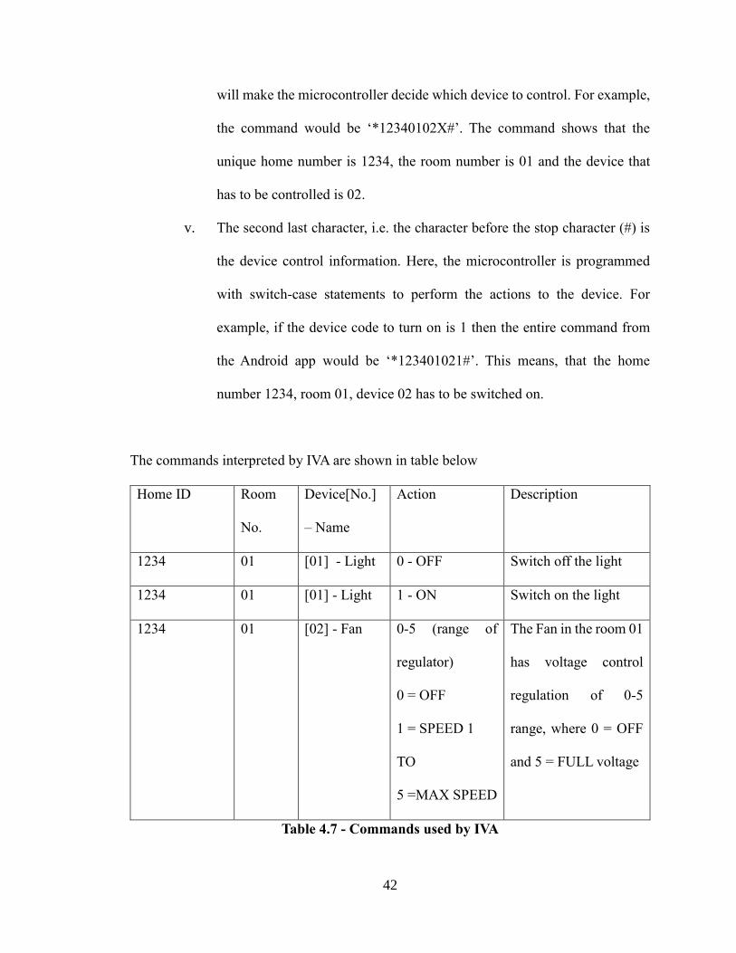
The commands interpreted by IVA are shown in table below
Home ID Room
No.
Device[No.]
– Name
Action Description
1234 01 [01] - Light 0 - OFF Switch off the light
1234 01 [01] - Light 1 - ON Switch on the light
1234 01 [02] - Fan 0-5 (range of
regulator)
0 = OFF
1 = SPEED 1
TO
5 =MAX SPEED
The Fan in the room 01
has voltage control
regulation of 0-5
range, where 0 = OFF
and 5 = FULL voltage
Table 4.7 - Commands used by IVA
43
4.5 Controlling actual devices
Arduino board has many I/O pins. These pins are used to send a 5V voltage across the line
to the connected devices. Arduino is very strong controller board. It has a pre-built
mechanism to power even the low level current operated hardware through the pin. It can
provide a current of 40 mA per I/O pin when it is pulled up. Thus, there is no need to supply
a separate power for components like LEDs, tone generating buzzers, etc. To pull up the
I/O pin, the Arduino has to be programmed with the pin number as an output port. For
example, if the pin number 5 has to be pulled up, a line in program has to be written
something like pinMode(5, OUTPUT). Here the pin number 5 will act as output pin and
will be internally pulled up. Thus, for example, when the Control Box receives the
command to switch the lights on, the microcontroller has to make pin number 27 high. This
is because, the relay switch connect to the microcontroller is via pin number 27. We can
see this in the schematic image 4.1. The line in the code to make a pin 27 high in Arduino
program is ‘digitalWrite(27, HIGH)’.
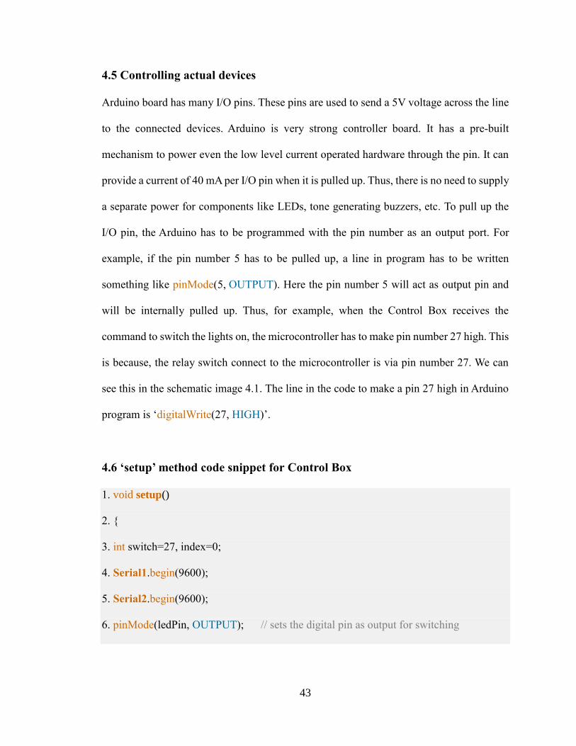
4.6 ‘setup’ method code snippet for Control Box
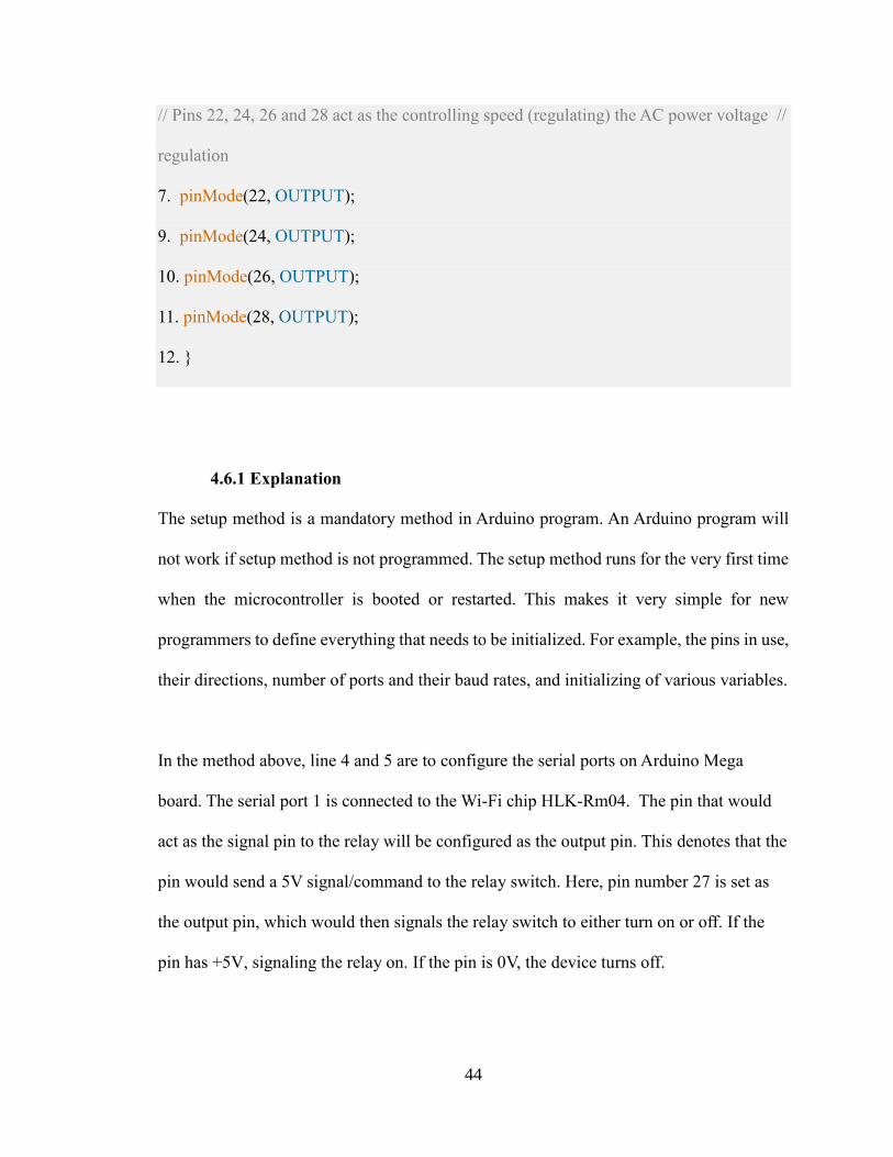
1. void setup()
2. {
3. int switch=27, index=0;
4. Serial1.begin(9600);
5. Serial2.begin(9600);
6. pinMode(ledPin, OUTPUT); // sets the digital pin as output for switching
44
// Pins 22, 24, 26 and 28 act as the controlling speed (regulating) the AC power voltage //
regulation
7. pinMode(22, OUTPUT);
9. pinMode(24, OUTPUT);
10. pinMode(26, OUTPUT);
11. pinMode(28, OUTPUT);
12. }
4.6.1 Explanation
The setup method is a mandatory method in Arduino program. An Arduino program will
not work if setup method is not programmed. The setup method runs for the very first time
when the microcontroller is booted or restarted. This makes it very simple for new
programmers to define everything that needs to be initialized. For example, the pins in use,
their directions, number of ports and their baud rates, and initializing of various variables.
In the method above, line 4 and 5 are to configure the serial ports on Arduino Mega
board. The serial port 1 is connected to the Wi-Fi chip HLK-Rm04. The pin that would
act as the signal pin to the relay will be configured as the output pin. This denotes that the
pin would send a 5V signal/command to the relay switch. Here, pin number 27 is set as
the output pin, which would then signals the relay switch to either turn on or off. If the
pin has +5V, signaling the relay on. If the pin is 0V, the device turns off.
45
Moreover, as explained in program comments, the pin numbers 22, 24, 26 and 28 are also
set as output pins to control the power voltage regulator.
4.7 ‘loop’ method code
0. void loop()
1. {
2. if(Serial1.available()) {
3. int inByte = Serial1.read();
4. //Serial.write(inByte);
5. inData[index] = inByte; // Store it
6. index++; // Increment where to write next
7. inData[index] = '\0';
8. if(gotit==1)
9. {
10. index=0;
11. gotit=0;
12. }
13. if(inData[0]=='*' && inData[1]=='1' && inData[2]=='3' && inData[3]=='0' && in
14. Data[4]=='2' && inData[5]=='0' && inData[6]=='1' && inData[7]=='0' &&
inData[8]=='1' 15. && inData[9]=='1' && inData[10]=='\0' )
16. {
17. digitalWrite(switch, HIGH); // sets the Relay switch on
46
18. //Action performed. Now listen to new command
19. gotit=1;
20. index=0;
21. }
22. else if(inData[0]=='*' && inData[1]=='1' && inData[2]=='3' && inData[3]=='0'
&& in 23. Data[4]=='2' && inData[5]=='0' && inData[6]=='1' &&
inData[7]=='0' && in 24. Data[8]=='1' && inData[9]=='0' &&
inData[10]=='\0' )//if(inData=="*130201010\n")
25. {
26. digitalWrite(switch, LOW); // sets the Relay switch off
27. // Action performed. Now listen to new command
28. gotit=1;
29. index=0;
30. }
31. else if(inData[0]=='*' && inData[1]=='1' && inData[2]=='3' && inData[3]=='0'
&& in 32. Data[4]=='2' && inData[5]=='0' && inData[6]=='1' && inData[7]=='0'
&& in 33. Data[8]=='2' && inData[9]=='0' && inData[10]=='\0'
)//if(inData=="*130201020\n")
34. {
35. Serial2.write(0); // write to dimmer module via serial port
36. gotit=1;
37. index=0;
38. }
47
39. else if(inData[0]=='*' && inData[1]=='1' && inData[2]=='3' && inData[3]=='0'
&& in 40. Data[4]=='2' && inData[5]=='0' && inData[6]=='1' && inData[7]=='0'
&& in 41. Data[8]=='2' && inData[9]=='1' && inData[10]=='\0'
)//if(inData=="*130201021\n")
42. {
43. Serial2.write(45); // write to dimmer module via serial port
44. gotit=1;
45. index=0;
46. }
47. else if(inData[0]=='*' && inData[1]=='1' && inData[2]=='3' && inData[3]=='0'
&& in 48. Data[4]=='2' && inData[5]=='0' && inData[6]=='1' && inData[7]=='0'
&& in 49. Data[8]=='2' && inData[9]=='2' && inData[10]=='\0'
)//if(inData=="*130201022\n")
50. {
51. Serial2.write(90); // write to dimmer module via serial port
52. gotit=1;
53. index=0;
54. }
55. else if(inData[0]=='*' && inData[1]=='1' && inData[2]=='3' && inData[3]=='0'
&& in 56. Data[4]=='2' && inData[5]=='0' && inData[6]=='1' &&
inData[7]=='0' && in 57. Data[8]=='2' && inData[9]=='3' &&
inData[10]=='\0' )//if(inData=="*130201023\n")
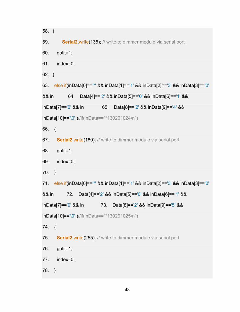
48
58. {
59. Serial2.write(135); // write to dimmer module via serial port
60. gotit=1;
61. index=0;
62. }
63. else if(inData[0]=='*' && inData[1]=='1' && inData[2]=='3' && inData[3]=='0'
&& in 64. Data[4]=='2' && inData[5]=='0' && inData[6]=='1' &&
inData[7]=='0' && in 65. Data[8]=='2' && inData[9]=='4' &&
inData[10]=='\0' )//if(inData=="*130201024\n")
66. {
67. Serial2.write(180); // write to dimmer module via serial port
68. gotit=1;
69. index=0;
70. }
71. else if(inData[0]=='*' && inData[1]=='1' && inData[2]=='3' && inData[3]=='0'
&& in 72. Data[4]=='2' && inData[5]=='0' && inData[6]=='1' &&
inData[7]=='0' && in 73. Data[8]=='2' && inData[9]=='5' &&
inData[10]=='\0' )//if(inData=="*130201025\n")
74. {
75. Serial2.write(255); // write to dimmer module via serial port
76. gotit=1;
77. index=0;
78. }
49
79. }
80. }
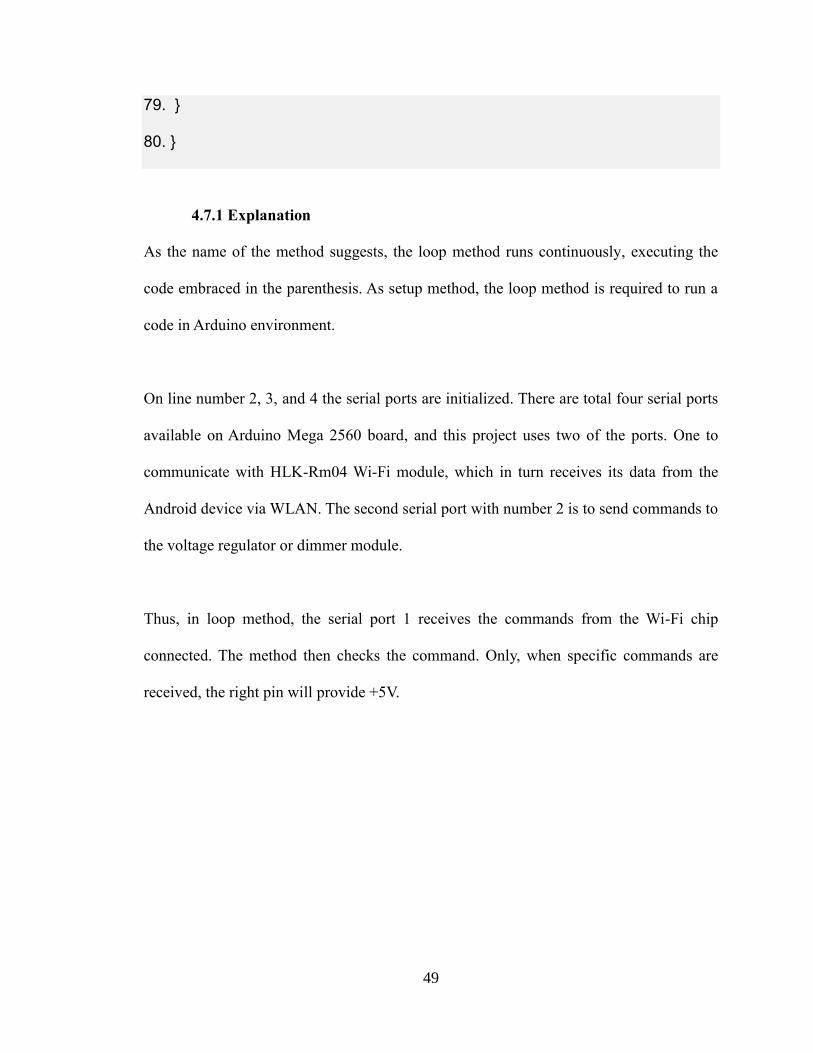
4.7.1 Explanation
As the name of the method suggests, the loop method runs continuously, executing the
code embraced in the parenthesis. As setup method, the loop method is required to run a
code in Arduino environment.
On line number 2, 3, and 4 the serial ports are initialized. There are total four serial ports
available on Arduino Mega 2560 board, and this project uses two of the ports. One to
communicate with HLK-Rm04 Wi-Fi module, which in turn receives its data from the
Android device via WLAN. The second serial port with number 2 is to send commands to
the voltage regulator or dimmer module.
Thus, in loop method, the serial port 1 receives the commands from the Wi-Fi chip
connected. The method then checks the command. Only, when specific commands are
received, the right pin will provide +5V.
50
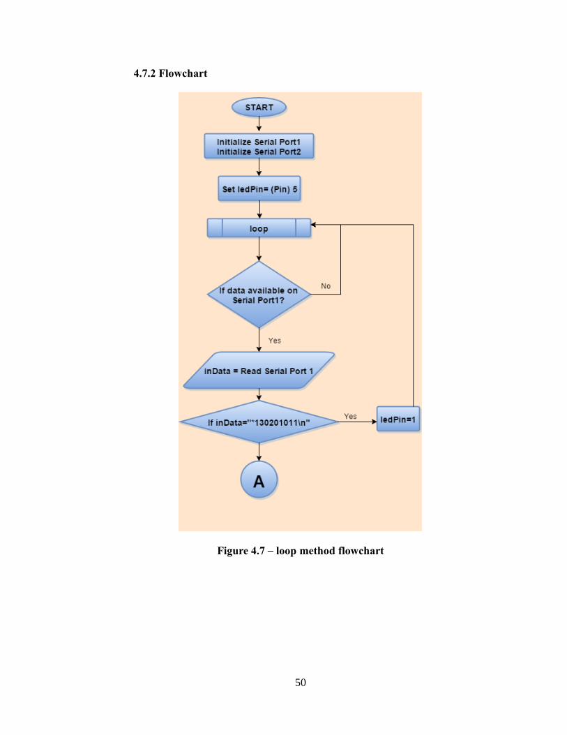
4.7.2 Flowchart
Figure 4.7 – loop method flowchart
51
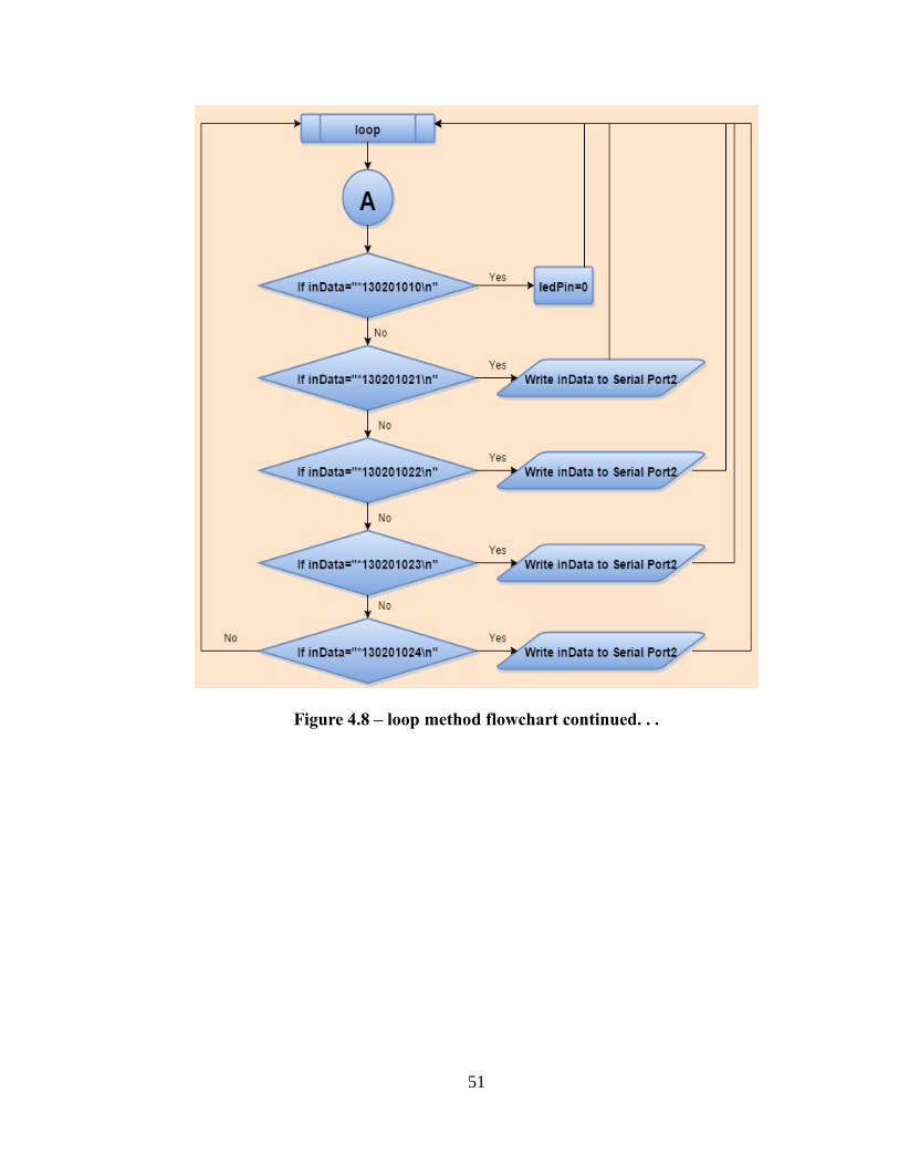
Figure 4.8 – loop method flowchart continued. . .
52
CHAPTER V
IVA’S SOFTWARE AND INTELLIGENCE
5.1 User Interface
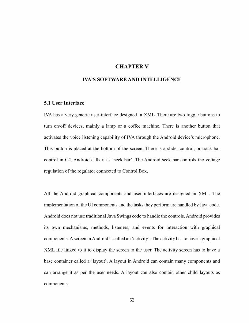
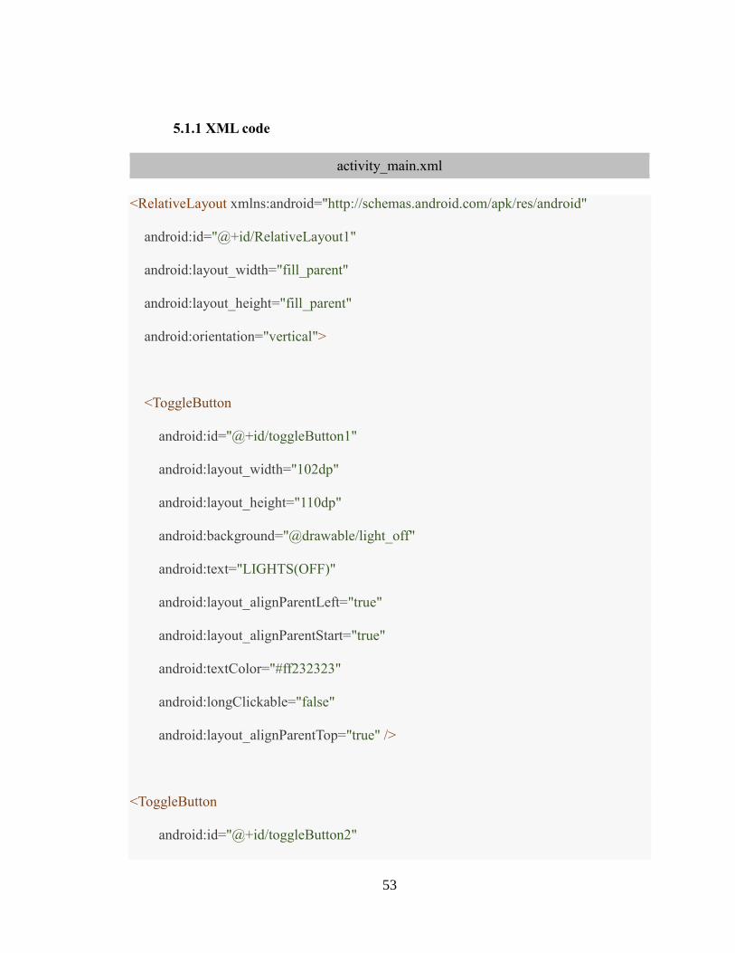
IVA has a very generic user-interface designed in XML. There are two toggle buttons to
turn on/off devices, mainly a lamp or a coffee machine. There is another button that
activates the voice listening capability of IVA through the Android device’s microphone.
This button is placed at the bottom of the screen. There is a slider control, or track bar
control in C#. Android calls it as ‘seek bar’. The Android seek bar controls the voltage
regulation of the regulator connected to Control Box.
All the Android graphical components and user interfaces are designed in XML. The
implementation of the UI components and the tasks they perform are handled by Java code.
Android does not use traditional Java Swings code to handle the controls. Android provides
its own mechanisms, methods, listeners, and events for interaction with graphical
components. A screen in Android is called an ‘activity’. The activity has to have a graphical
XML file linked to it to display the screen to the user. The activity screen has to have a
base container called a ‘layout’. A layout in Android can contain many components and
can arrange it as per the user needs. A layout can also contain other child layouts as
components.
53
5.1.1 XML code
activity_main.xml
<RelativeLayout xmlns:android="http://schemas.android.com/apk/res/android"
android:id="@+id/RelativeLayout1"
android:layout_width="fill_parent"
android:layout_height="fill_parent"
android:orientation="vertical">
<ToggleButton
android:id="@+id/toggleButton1"
android:layout_width="102dp"
android:layout_height="110dp"
android:background="@drawable/light_off"
android:text="LIGHTS(OFF)"
android:layout_alignParentLeft="true"
android:layout_alignParentStart="true"
android:textColor="#ff232323"
android:longClickable="false"
android:layout_alignParentTop="true" />
<ToggleButton
android:id="@+id/toggleButton2"
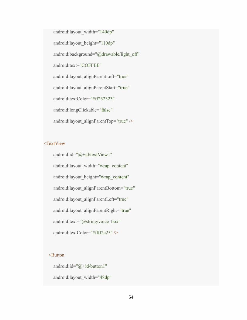
54
android:layout_width="140dp"
android:layout_height="110dp"
android:background="@drawable/light_off"
android:text="COFFEE"
android:layout_alignParentLeft="true"
android:layout_alignParentStart="true"
android:textColor="#ff232323"
android:longClickable="false"
android:layout_alignParentTop="true" />
<TextView
android:id="@+id/textView1"
android:layout_width="wrap_content"
android:layout_height="wrap_content"
android:layout_alignParentBottom="true"
android:layout_alignParentLeft="true"
android:layout_alignParentRight="true"
android:text="@string/voice_box"
android:textColor="#ffff2c25" />
<Button
android:id="@+id/button1"
android:layout_width="48dp"
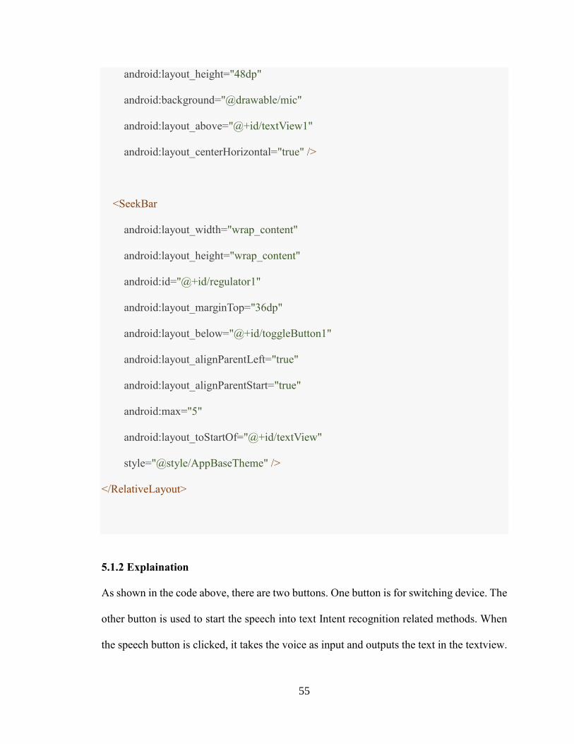
55
android:layout_height="48dp"
android:background="@drawable/mic"
android:layout_above="@+id/textView1"
android:layout_centerHorizontal="true" />
<SeekBar
android:layout_width="wrap_content"
android:layout_height="wrap_content"
android:id="@+id/regulator1"
android:layout_marginTop="36dp"
android:layout_below="@+id/toggleButton1"
android:layout_alignParentLeft="true"
android:layout_alignParentStart="true"
android:max="5"
android:layout_toStartOf="@+id/textView"
style="@style/AppBaseTheme" />
</RelativeLayout>
5.1.2 Explaination
As shown in the code above, there are two buttons. One button is for switching device. The
other button is used to start the speech into text Intent recognition related methods. When
the speech button is clicked, it takes the voice as input and outputs the text in the textview.
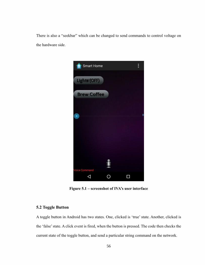
56
There is also a “seekbar” which can be changed to send commands to control voltage on
the hardware side.
Figure 5.1 – screenshot of IVA’s user interface
5.2 Toggle Button
A toggle button in Android has two states. One, clicked is ‘true’ state. Another, clicked is
the ‘false’ state. A click event is fired, when the button is pressed. The code then checks the
current state of the toggle button, and send a particular string command on the network.
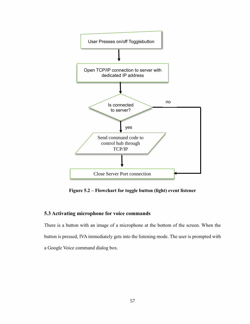
57
Figure 5.2 – Flowchart for toggle button (light) event listener
5.3 Activating microphone for voice commands
There is a button with an image of a microphone at the bottom of the screen. When the
button is pressed, IVA immediately gets into the listening mode. The user is prompted with
a Google Voice command dialog box.
User Presses on/off Togglebutton
Open TCP/IP connection to server with dedicated IP address
Is connected to server?
yes
Send command code to
control hub through
TCP/IP
Close Server Port connection
no
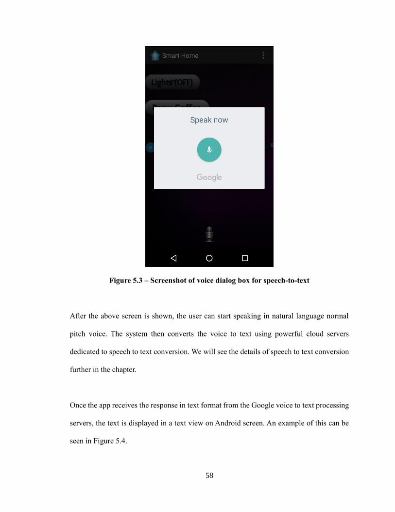
58
Figure 5.3 – Screenshot of voice dialog box for speech-to-text
After the above screen is shown, the user can start speaking in natural language normal
pitch voice. The system then converts the voice to text using powerful cloud servers
dedicated to speech to text conversion. We will see the details of speech to text conversion
further in the chapter.
Once the app receives the response in text format from the Google voice to text processing
servers, the text is displayed in a text view on Android screen. An example of this can be
seen in Figure 5.4.
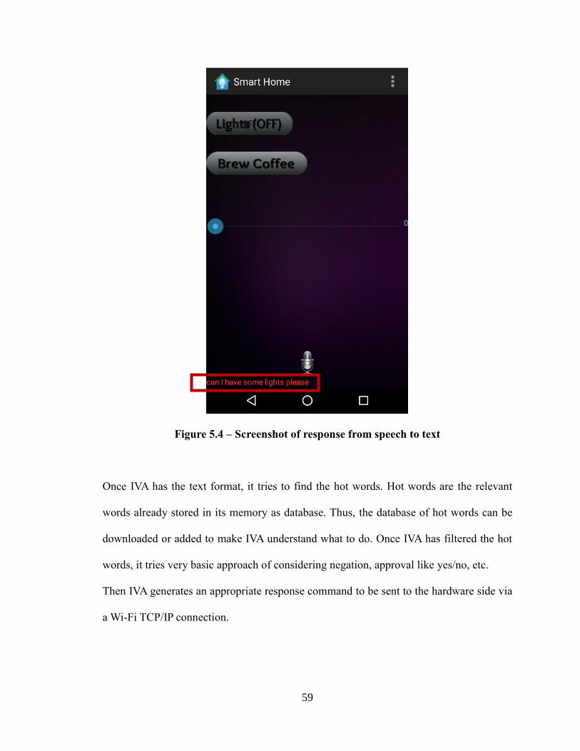
59
Figure 5.4 – Screenshot of response from speech to text
Once IVA has the text format, it tries to find the hot words. Hot words are the relevant
words already stored in its memory as database. Thus, the database of hot words can be
downloaded or added to make IVA understand what to do. Once IVA has filtered the hot
words, it tries very basic approach of considering negation, approval like yes/no, etc.
Then IVA generates an appropriate response command to be sent to the hardware side via
a Wi-Fi TCP/IP connection.
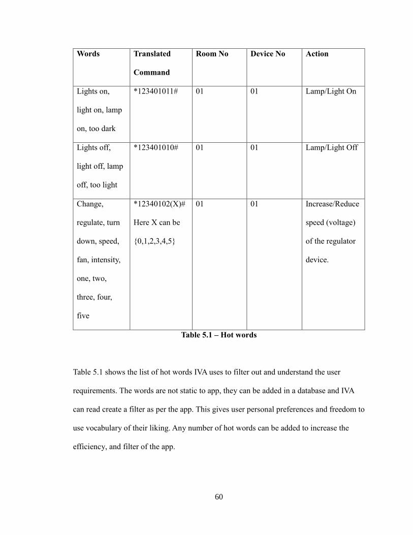
60
Words Translated
Command
Room No Device No Action
Lights on,
light on, lamp
on, too dark
*123401011# 01 01 Lamp/Light On
Lights off,
light off, lamp
off, too light
*123401010# 01 01 Lamp/Light Off
Change,
regulate, turn
down, speed,
fan, intensity,
one, two,
three, four,
five
*12340102(X)#
Here X can be
{0,1,2,3,4,5}
01 01 Increase/Reduce
speed (voltage)
of the regulator
device.
Table 5.1 – Hot words
Table 5.1 shows the list of hot words IVA uses to filter out and understand the user
requirements. The words are not static to app, they can be added in a database and IVA
can read create a filter as per the app. This gives user personal preferences and freedom to
use vocabulary of their liking. Any number of hot words can be added to increase the
efficiency, and filter of the app.
61
5.4 How speech to text conversion works
The most essential piece of IVA’s software is to interpret natural language from the user.
It uses Android’s speech to text APIs provided by Google to convert spoken words to text
format.
The app uses microphones in Android device to record the speech into an audio file. The
file is then sent to Google speech to text servers. The servers process the audio file to
generate a textual response to the Android device via Internet. Thus, IVA needs Internet if
to connect with the Google servers to send the audio file it captured via microphone.
5.4.1 Speech-to-text Processing
The process of converting speech to text is bit more complicated than just comparing voice
inputs with saved templates. Once the audio is sent to the dedicated Google cloud servers,
it then converts it from Analog to Digital format. To do this, the server takes small samples,
or digitizes, the sound by taking precise measurements of the wave at frequent intervals.
Then, the system filters these sampled sound to remove unwanted noise, and sometimes
separate it into different bands of frequency (frequency is the wavelength of the sound
waves, heard by humans as differences in pitch). It is also used to adjust volume changes,
as people don't always speak at the same speed and volume. Thus, the sound must be
adjusted to match the speed of the template sound samples already stored in the system's
memory.
Next, the signal is divided into small segments as short as a few hundredths of a second, or
62
even thousandths in the case of consonant sounds -- consonant stops produced by
obstructing airflow in the vocal tract -- like "p" or "t." The program then matches these
segments to known phonemes in the appropriate language. A phoneme is the smallest
element of a language -- a representation of the sounds we make and put together to form
meaningful expressions. As per experts, there are roughly 40 phonemes in the English
language, although different linguists have different opinions on the exact number.
Next step is the actual ongoing research to make super powerful processing computers
analyze the spoken words to accurate text. There are various ways to make this happen.
Different statistical analysis models are used to predict the words by searching for
appropriate patterns in the fed data. Learning to find the pattern even for different accents
and dialects is done by machine learning algorithms such as regressions, data analysis and
many others. More information can be found in many research papers on the topic.
The server then finds for appropriate sounding words with phonetics in the database to
replace the spoken input with output as text.
A brief overview of the above explanation can be visualized in the Figure 5.5 below.
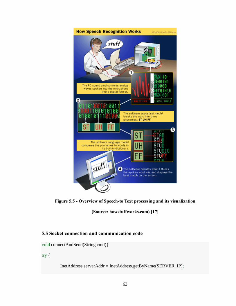
63
Figure 5.5 - Overview of Speech-to Text processing and its visualization
(Source: howstuffworks.com) [17]
5.5 Socket connection and communication code
void connectAndSend(String cmd){
try {
InetAddress serverAddr = InetAddress.getByName(SERVER_IP);
64
socket = new Socket(serverAddr, SERVERPORT); // EstablishingConnection
String str = HomeId+cmd; // Command example (01011)
// append command to home ID Room(01) – Device (01) Action(1)
PrintWriter out = new PrintWriter(new BufferedWriter(
new OutputStreamWriter(socket.getOutputStream())),
true);
out.println(str); // Sending actual data
socket.close(); // Close open connection
} catch (UnknownHostException e1) {
e1.printStackTrace();
} catch (IOException e1) {
e1.printStackTrace();
}
} // End method connectAndSend()
This code shows the connection to the server. The SERVER_IP is a string. The IP address
is a specific Control Box WLAN network address already programmed in the app. Once
the connection is established, an output stream channel is used to pass the information on
the network.
5.6 Filtering hot words code
void filterHotWords(String line) {
//Filter using if() statement
65
if (line.toLowerCase().contains("lamp") || line.toLowerCase().contains("light") ||
line.toLowerCase().contains("bulb") || line.toLowerCase().contains("lights") ||
(line.toLowerCase().contains("dark"))) { // AND (&&)
if (line.toLowerCase().contains("so") || line.toLowerCase().contains("too") ||
line.toLowerCase().contains("on") && !line.toLowerCase().contains("not")) {
{
connectAndSend ("01011"); //Send command to witch on Lights
}
} //End method
In this code, a small example of how IVA filter’s hot words from user spoken command.
This filter, HotWords method is named after the Google speech to text server responds with
converts voice commands to text format. This text is then passed to filter the important/hot
words to understand what user wants. If specific words are found in a set required manner,
the connectAndSend method is called.
66
CHAPTER VI
CONCLUSION AND FUTURE WORK
6.1 Conclusion
The aim of this thesis was to study, assume, estimate and reverse engineer existing systems
in order to design and develop our own home automation system. This goal was successful
as IVA’s design was heavily influenced by the studied home automation architectures.
The network architecture resembles close to that of Belkin’s Wemo switch, whereas the
voice commands and natural language processing is influenced by the Amazon’s Echo
design. A device in a room idea was inculcated in IVA’s architecture by understanding how
Nest thermostat works. Thus, the working prototype architecture of Intelligent Voice
Activated Home Automation (IVA) was developed and tested based on combination of
number of home automation systems designed and developed by few of the top innovating
software and hardware companies like Google, Amazon, Apple, and Belkin.
6.2 Future Work
The future scope for IVA can be huge. There are few ideas that we are discussing to make
IVA more powerful, intelligent, scalable, and to become better overall for home
automation.
67
6.2.1 Improving voice capturing
The Android device’s microphone can be replaced with a sensitive high noise cancelling
dedicated to microphones located in each room of the house. Then, the microphones can
be connected to an Android device via a Bluetooth radio, or a Wi-Fi connection. This would
eliminate the need for user to have the Android devices close to them, while giving voice
commands.
6.2.2 Scalability for adding new devices
As the Arduino platform is highly flexible and can connect to most of the hardware, which
is compatible with a microcontroller, attaching or developing more devices working with
IVA’s system would not be a problem. The type and number of devices that can be
compatible with IVA is huge. For example, biometric ability can be provided by attaching
a fingerprint sensor to a Control Box. Another example can be adding motorized devices
like window blinds controller, garage shutter door controller, and many more devices.
Devices can be developed with a general Arduino architecture in mind to make it work
with IVA.
As all the low level controls are handled by the Control Box hardware, adding a device
connection and command for IVA’s app is not at all a problem. The scalability with IVA
can only be the limit as much as limitation of developer’s imagination.
68
6.2.3 Improving IVA’s intelligence
Currently, we are using very basic level of code to filter hot words that IVA understands
and perform certain, limited tasks as per the voice commands.
IVA can become more close to artificial learning and interaction based on machine learning
algorithm. As machine learning is current most advance topic. It provides computer with
pattern filtering ability, which can further be used to perform tasks in specific domain. The
Information Technology industry is booming with research in the subject of machine
learning. We can also see new technologies using it to simulate limited intelligence such as
self-driving cars, digital assistants, cancer detecting medical devices, and many more.
We can use similar approaches to make IVA a step closer to being intelligent.
69
REFERENCES
[1] AVC: How Big is Tablet Market: http://avc.com/2014/04/how-big-is-the-tablet-
market/
[2] Home Automation history: http://en.wikipedia.org/wiki/Home_automation#History
[3] Nest Thermostat: https://nest.com/thermostat/meet-nest-thermostat
[4] Pew Research center: http://www.pewInternet.org/2014/04/03/older-adults-and-
technology-use/
[5] Business College at University of Alabama:
http://businessdegrees.uab.edu/resources/infographics/the-future-of-mobile-application/
[6] Westinghouse Electric: http://en.wikipedia.org/wiki/Westinghouse_Electric_Company
[7] Link-Labs: http://www.link-labs.com/zigbee-vs-wifi-802-11ah/
[8] Axial Exchange on Older Americans use of smartphones:
http://axialexchange.com/blog/article/sanity-check-do-older-americans-use-smartphones
[9] Techcrunch article on smartphone market in developing markets:
http://techcrunch.com/2012/05/27/mobile-developing-world/
[10] Telegraph article on smartphone usage and future in developing countries:
http://www.telegraph.co.uk/finance/newsbysector/mediatechnologyandtelecoms/1112699
7/Emerging-markets-will-lead-smartphone-growth-next-year.html
[11] Telecomengine: http://www.telecomengine.com/article/future-IoT-connectivity
[12] Arduino Wiki: https://arduino-info.wikispaces.com/MegaQuickRef
[13] Arduino - Home: www.arduino.cc
[14] HiLink Co, Ltd HLK-RM04 chip:
70
http://www.hlktech.net/product_detail.php?ProId=39
[15] Google buys Nest news: http://www.independent.co.uk/life-style/gadgets-and-
tech/google-buys-nest-what-does-this-mean- for-home-automation-the-internet-of-
things-and-apple-9058217.html
[16] Android Developers: http://developer.android.com/index.html
[17] Programming questions and support: http://stackoverflow.com/
[18] Arduino and Android through Wi-Fi:
http://electronics.stackexchange.com/questions/56633/simplest-way-to-connect-anrduino
-to-android-wirelessly
[19] ABI Research on home automation future: https://www.abiresearch.com/press/15-
million-home-automation-systems-installed-in-th
[20] Speech Recognition by HowStuffWorks:
http://electronics.howstuffworks.com/gadgets/high-tech-gadgets/speech-recognition1.htm
[21] Business Insider smartphone vs PC: http://www.businessinsider.com/smartphone-
bigger-than-pc-market-2011-2
[22] Forbes: Mobile Is Eating the World:
http://www.forbes.com/sites/louiscolumbus/2014/11/09/mobile-is-eating-the-world/
[23] Gigaom.com: https://gigaom.com/2014/10/03/belkin-looks-at-the-smart-home-and-
doesnt-see-a-place-for-hubs/
[24] wikispace Arduino pinouts: https://arduino-info.wikispaces.com/MegaQuickRef
[25] ZigBee as Communication Platform for smart house applications: International
Journal of Engineering - ISSN: 1584–2673
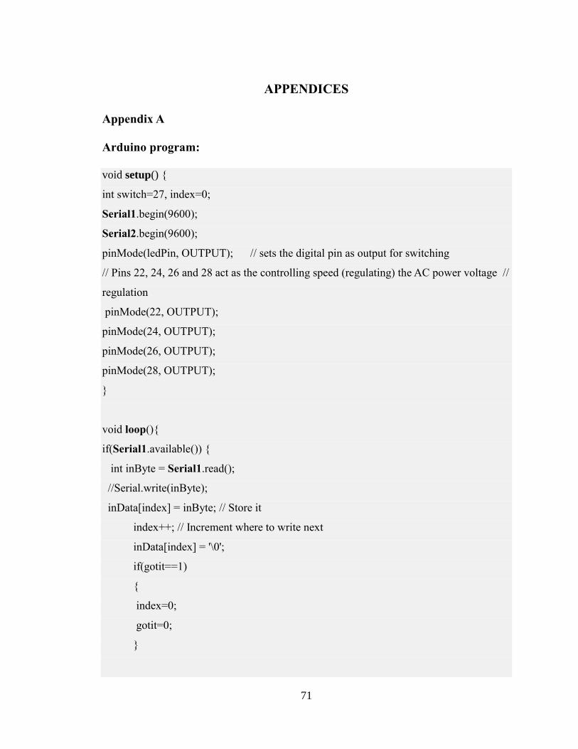
71
APPENDICES
Appendix A
Arduino program:
void setup() {
int switch=27, index=0;
Serial1.begin(9600);
Serial2.begin(9600);
pinMode(ledPin, OUTPUT); // sets the digital pin as output for switching
// Pins 22, 24, 26 and 28 act as the controlling speed (regulating) the AC power voltage //
regulation
pinMode(22, OUTPUT);
pinMode(24, OUTPUT);
pinMode(26, OUTPUT);
pinMode(28, OUTPUT);
}
void loop(){
if(Serial1.available()) {
int inByte = Serial1.read();
//Serial.write(inByte);
inData[index] = inByte; // Store it
index++; // Increment where to write next
inData[index] = '\0';
if(gotit==1)
{
index=0;
gotit=0;
}
72
if(inData[0]=='*' && inData[1]=='1' && inData[2]=='3' && inData[3]=='0' && in
Data[4]=='2' && inData[5]=='0' && inData[6]=='1' && inData[7]=='0' &&
inData[8]=='1' 15. && inData[9]=='1' && inData[10]=='\0' )
{
digitalWrite(switch, HIGH); // sets the Relay switch on
//Action performed. Now listen to new command
gotit=1;
index=0;
}
else if(inData[0]=='*' && inData[1]=='1' && inData[2]=='3' && inData[3]=='0' &&
inData[4]=='2' && inData[5]=='0' && inData[6]=='1' && inData[7]=='0' && in
Data[8]=='1' && inData[9]=='0' && inData[10]=='\0' )//if(inData=="*130201010\n")
{
digitalWrite(switch, LOW); // sets the Relay switch off
// Action performed. Now listen to new command
gotit=1;
index=0;
}
else if(inData[0]=='*' && inData[1]=='1' && inData[2]=='3' && inData[3]=='0' &&
inData[4]=='2' && inData[5]=='0' && inData[6]=='1' && inData[7]=='0' && in
Data[8]=='2' && inData[9]=='0' && inData[10]=='\0' )//if(inData=="*130201020\n")
{
Serial2.write(0); // write to dimmer module via serial port
gotit=1;
index=0;
}
else if(inData[0]=='*' && inData[1]=='1' && inData[2]=='3' && inData[3]=='0' &&
inData[4]=='2' && inData[5]=='0' && inData[6]=='1' && inData[7]=='0' &&
inData[8]=='2' && inData[9]=='1' && inData[10]=='\0' )//if(inData=="*130201021\n")
{
Serial2.write(45); // write to dimmer module via serial port
73
gotit=1;
index=0;
}
else if(inData[0]=='*' && inData[1]=='1' && inData[2]=='3' && inData[3]=='0' &&
inData[4]=='2' && inData[5]=='0' && inData[6]=='1' && inData[7]=='0' &&
inData[8]=='2' && inData[9]=='2' && inData[10]=='\0' )//if(inData=="*130201022\n")
{
Serial2.write(90); // write to dimmer module via serial port
gotit=1;
index=0;
}
else if(inData[0]=='*' && inData[1]=='1' && inData[2]=='3' && inData[3]=='0' &&
inData[4]=='2' && inData[5]=='0' && inData[6]=='1' && inData[7]=='0' &&
inData[8]=='2' && inData[9]=='3' && inData[10]=='\0' )//if(inData=="*130201023\n")
{
Serial2.write(135); // write to dimmer module via serial port
gotit=1;
index=0;
}
else if(inData[0]=='*' && inData[1]=='1' && inData[2]=='3' && inData[3]=='0' &&
inData[4]=='2' && inData[5]=='0' && inData[6]=='1' && inData[7]=='0' &&
inData[8]=='2' && inData[9]=='4' && inData[10]=='\0' )//if(inData=="*130201024\n")
{
Serial2.write(180); // write to dimmer module via serial port
gotit=1;
index=0;
}
else if(inData[0]=='*' && inData[1]=='1' && inData[2]=='3' && inData[3]=='0' &&
inData[4]=='2' && inData[5]=='0' && inData[6]=='1' && inData[7]=='0' &&
inData[8]=='2' && inData[9]=='5' && inData[10]=='\0' )//if(inData=="*130201025\n")
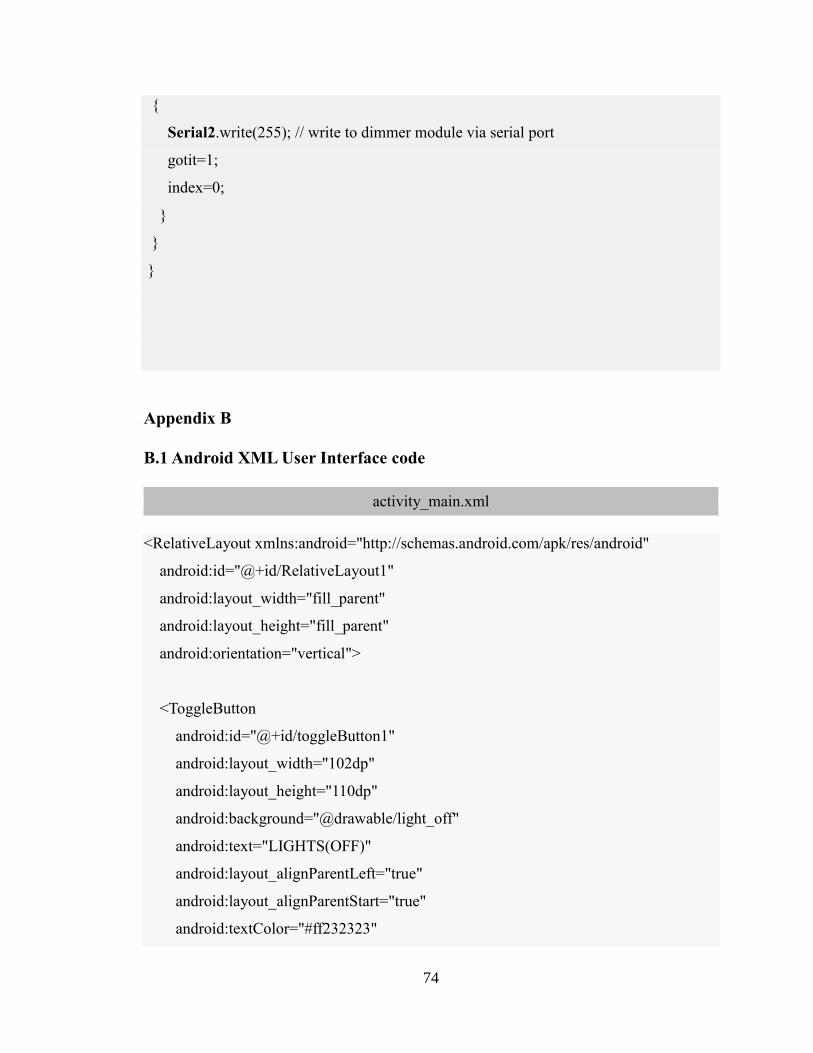
74
{
Serial2.write(255); // write to dimmer module via serial port
gotit=1;
index=0;
}
}
}
Appendix B
B.1 Android XML User Interface code
activity_main.xml
<RelativeLayout xmlns:android="http://schemas.android.com/apk/res/android"
android:id="@+id/RelativeLayout1"
android:layout_width="fill_parent"
android:layout_height="fill_parent"
android:orientation="vertical">
<ToggleButton
android:id="@+id/toggleButton1"
android:layout_width="102dp"
android:layout_height="110dp"
android:background="@drawable/light_off"
android:text="LIGHTS(OFF)"
android:layout_alignParentLeft="true"
android:layout_alignParentStart="true"
android:textColor="#ff232323"
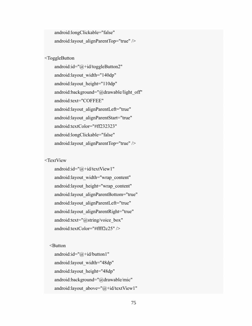
75
android:longClickable="false"
android:layout_alignParentTop="true" />
<ToggleButton
android:id="@+id/toggleButton2"
android:layout_width="140dp"
android:layout_height="110dp"
android:background="@drawable/light_off"
android:text="COFFEE"
android:layout_alignParentLeft="true"
android:layout_alignParentStart="true"
android:textColor="#ff232323"
android:longClickable="false"
android:layout_alignParentTop="true" />
<TextView
android:id="@+id/textView1"
android:layout_width="wrap_content"
android:layout_height="wrap_content"
android:layout_alignParentBottom="true"
android:layout_alignParentLeft="true"
android:layout_alignParentRight="true"
android:text="@string/voice_box"
android:textColor="#ffff2c25" />
<Button
android:id="@+id/button1"
android:layout_width="48dp"
android:layout_height="48dp"
android:background="@drawable/mic"
android:layout_above="@+id/textView1"
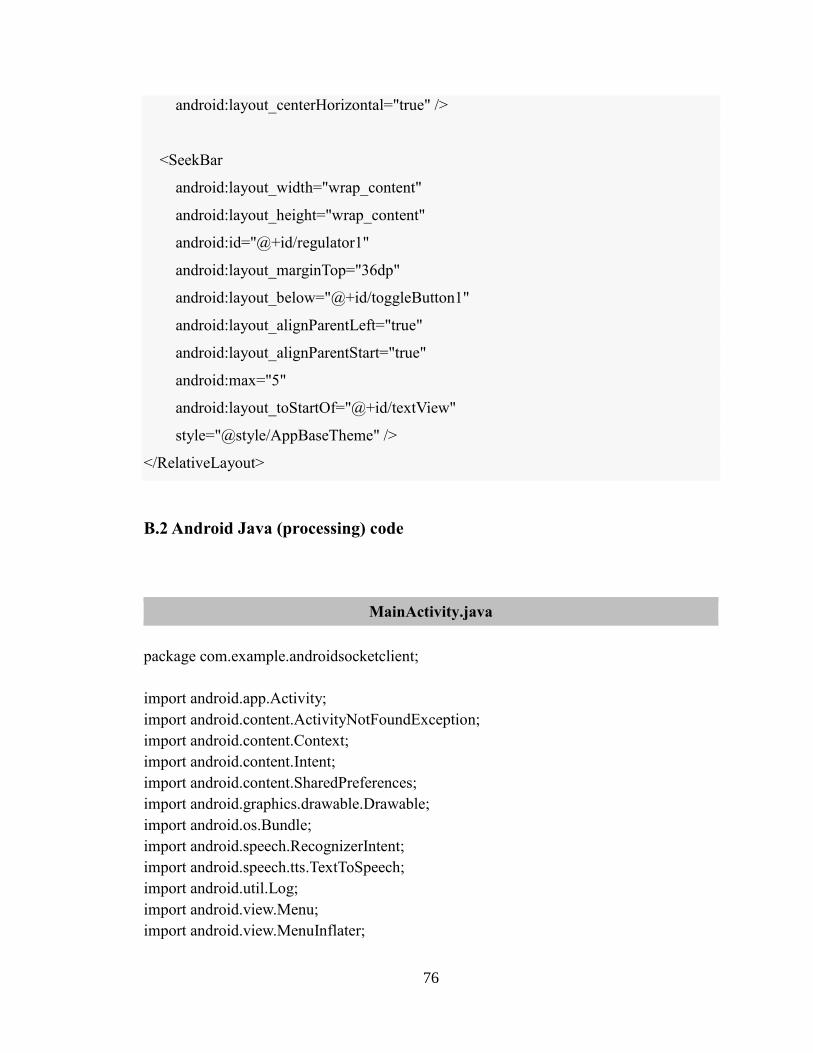
76
android:layout_centerHorizontal="true" />
<SeekBar
android:layout_width="wrap_content"
android:layout_height="wrap_content"
android:id="@+id/regulator1"
android:layout_marginTop="36dp"
android:layout_below="@+id/toggleButton1"
android:layout_alignParentLeft="true"
android:layout_alignParentStart="true"
android:max="5"
android:layout_toStartOf="@+id/textView"
style="@style/AppBaseTheme" />
</RelativeLayout>
B.2 Android Java (processing) code
MainActivity.java
package com.example.androidsocketclient;
import android.app.Activity;
import android.content.ActivityNotFoundException;
import android.content.Context;
import android.content.Intent;
import android.content.SharedPreferences;
import android.graphics.drawable.Drawable;
import android.os.Bundle;
import android.speech.RecognizerIntent;
import android.speech.tts.TextToSpeech;
import android.util.Log;
import android.view.Menu;
import android.view.MenuInflater;
77
import android.view.MenuItem;
import android.view.View;
import android.widget.Button;
import android.widget.EditText;
import android.widget.SeekBar;
import android.widget.TextView;
import android.widget.Toast;
import android.widget.ToggleButton;
import java.io.BufferedReader;
import java.io.BufferedWriter;
import java.io.IOException;
import java.io.InputStreamReader;
import java.io.OutputStreamWriter;
import java.io.PrintWriter;
import java.net.InetAddress;
import java.net.Socket;
import java.net.UnknownHostException;
import java.util.ArrayList;
import java.util.Locale;
import android.os.Handler;
public class MainActivity extends Activity {
protected static final int RESULT_SPEECH = 1;
private static final int SERVERPORT = 8080;
String SERVER_IP="10.0.0.14";
String HomeId="*1302";
public ToggleButton lamp1;
public Button mic, button2;
public TextView voiceCommandBox, regulatorStatusLabel;
public EditText edText1;
public SeekBar regulator1;
public TextToSpeech tts;
String regulatorProgress="0";
Thread t;
Drawable lamp1_on_image, lamp1_off_image;
private Socket socket;
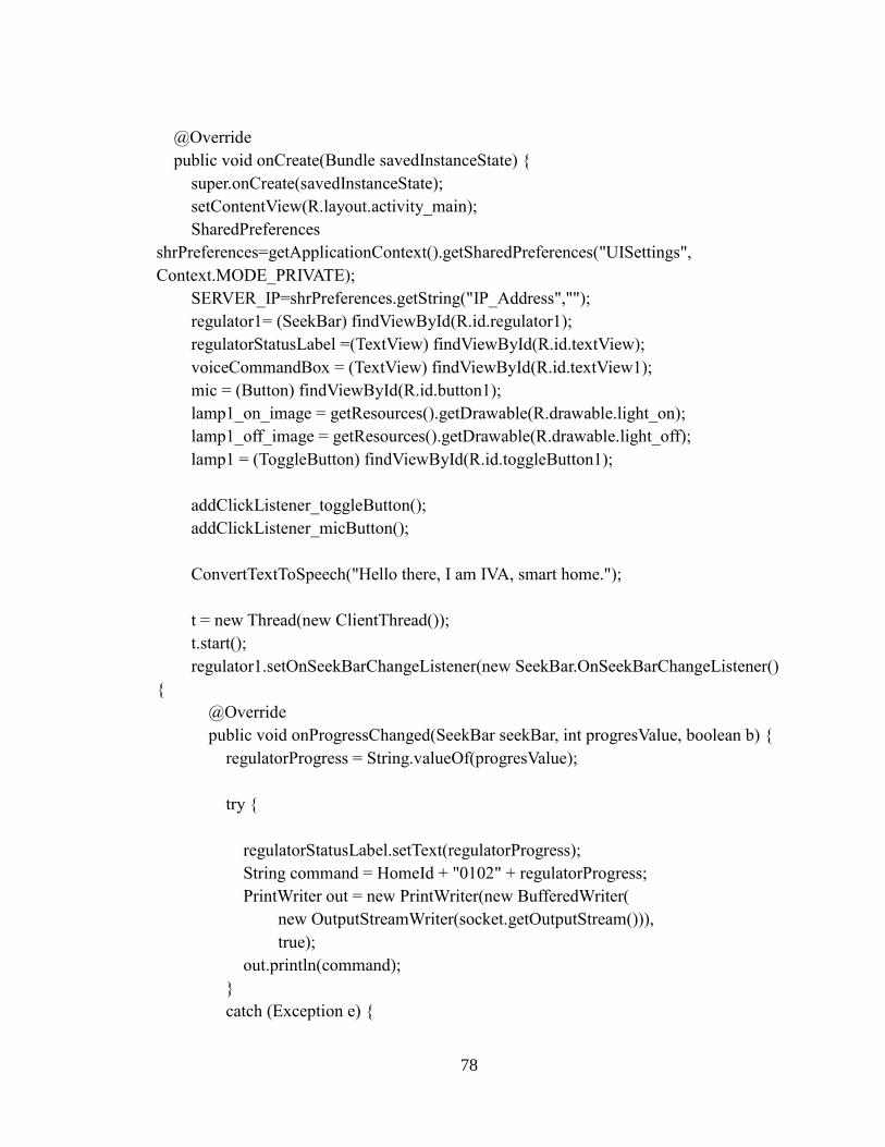
78
@Override
public void onCreate(Bundle savedInstanceState) {
super.onCreate(savedInstanceState);
setContentView(R.layout.activity_main);
SharedPreferences
shrPreferences=getApplicationContext().getSharedPreferences("UISettings",
Context.MODE_PRIVATE);
SERVER_IP=shrPreferences.getString("IP_Address","");
regulator1= (SeekBar) findViewById(R.id.regulator1);
regulatorStatusLabel =(TextView) findViewById(R.id.textView);
voiceCommandBox = (TextView) findViewById(R.id.textView1);
mic = (Button) findViewById(R.id.button1);
lamp1_on_image = getResources().getDrawable(R.drawable.light_on);
lamp1_off_image = getResources().getDrawable(R.drawable.light_off);
lamp1 = (ToggleButton) findViewById(R.id.toggleButton1);
addClickListener_toggleButton();
addClickListener_micButton();
ConvertTextToSpeech("Hello there, I am IVA, smart home.");
t = new Thread(new ClientThread());
t.start();
regulator1.setOnSeekBarChangeListener(new SeekBar.OnSeekBarChangeListener()
{
@Override
public void onProgressChanged(SeekBar seekBar, int progresValue, boolean b) {
regulatorProgress = String.valueOf(progresValue);
try {
regulatorStatusLabel.setText(regulatorProgress);
String command = HomeId + "0102" + regulatorProgress;
PrintWriter out = new PrintWriter(new BufferedWriter(
new OutputStreamWriter(socket.getOutputStream())),
true);
out.println(command);
}
catch (Exception e) {
79
Toast.makeText(getApplicationContext(),"There is some problem connecting
to the device. Please check your connection",Toast.LENGTH_SHORT).show();
e.printStackTrace();
e.printStackTrace();
}
}
@Override
public void onStartTrackingTouch(SeekBar seekBar) {
}
@Override
public void onStopTrackingTouch(SeekBar seekBar) {
}
});
}
@Override
public boolean onCreateOptionsMenu(Menu menu) {
MenuInflater inflater = getMenuInflater();
inflater.inflate(R.menu.main, menu);
return true;
}
@Override
protected void onPause() {
if(tts != null){
tts.stop();
tts.shutdown();
}
super.onPause();
}
@Override
public boolean onOptionsItemSelected(MenuItem item) {
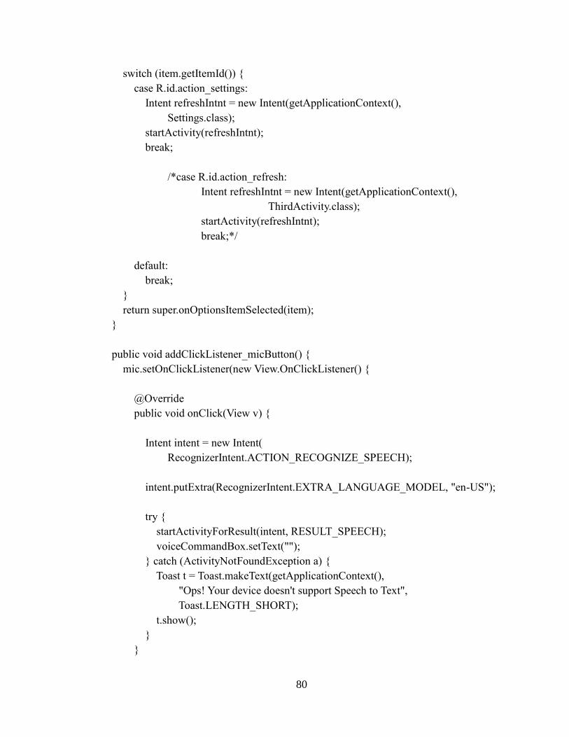
80
switch (item.getItemId()) {
case R.id.action_settings:
Intent refreshIntnt = new Intent(getApplicationContext(),
Settings.class);
startActivity(refreshIntnt);
break;
/*case R.id.action_refresh:
Intent refreshIntnt = new Intent(getApplicationContext(),
ThirdActivity.class);
startActivity(refreshIntnt);
break;*/
default:
break;
}
return super.onOptionsItemSelected(item);
}
public void addClickListener_micButton() {
mic.setOnClickListener(new View.OnClickListener() {
@Override
public void onClick(View v) {
Intent intent = new Intent(
RecognizerIntent.ACTION_RECOGNIZE_SPEECH);
intent.putExtra(RecognizerIntent.EXTRA_LANGUAGE_MODEL, "en-US");
try {
startActivityForResult(intent, RESULT_SPEECH);
voiceCommandBox.setText("");
} catch (ActivityNotFoundException a) {
Toast t = Toast.makeText(getApplicationContext(),
"Ops! Your device doesn't support Speech to Text",
Toast.LENGTH_SHORT);
t.show();
}
}
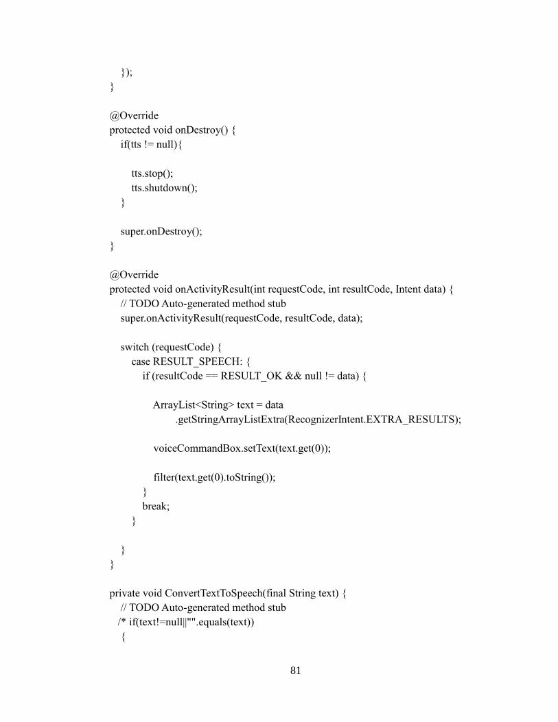
81
});
}
@Override
protected void onDestroy() {
if(tts != null){
tts.stop();
tts.shutdown();
}
super.onDestroy();
}
@Override
protected void onActivityResult(int requestCode, int resultCode, Intent data) {
// TODO Auto-generated method stub
super.onActivityResult(requestCode, resultCode, data);
switch (requestCode) {
case RESULT_SPEECH: {
if (resultCode == RESULT_OK && null != data) {
ArrayList<String> text = data
.getStringArrayListExtra(RecognizerIntent.EXTRA_RESULTS);
voiceCommandBox.setText(text.get(0));
filter(text.get(0).toString());
}
break;
}
}
}
private void ConvertTextToSpeech(final String text) {
// TODO Auto-generated method stub
/* if(text!=null||"".equals(text))
{
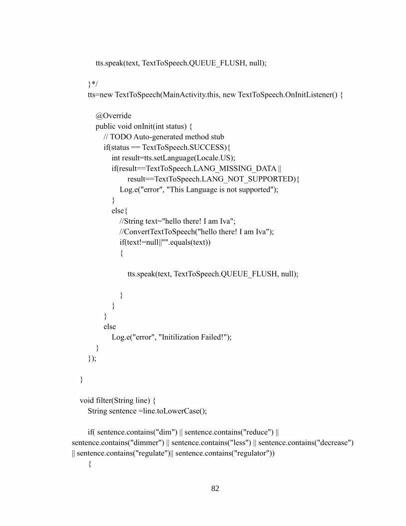
82
tts.speak(text, TextToSpeech.QUEUE_FLUSH, null);
}*/
tts=new TextToSpeech(MainActivity.this, new TextToSpeech.OnInitListener() {
@Override
public void onInit(int status) {
// TODO Auto-generated method stub
if(status == TextToSpeech.SUCCESS){
int result=tts.setLanguage(Locale.US);
if(result==TextToSpeech.LANG_MISSING_DATA ||
result==TextToSpeech.LANG_NOT_SUPPORTED){
Log.e("error", "This Language is not supported");
}
else{
//String text="hello there! I am Iva";
//ConvertTextToSpeech("hello there! I am Iva");
if(text!=null||"".equals(text))
{
tts.speak(text, TextToSpeech.QUEUE_FLUSH, null);
}
}
}
else
Log.e("error", "Initilization Failed!");
}
});
}
void filter(String line) {
String sentence =line.toLowerCase();
if( sentence.contains("dim") || sentence.contains("reduce") ||
sentence.contains("dimmer") || sentence.contains("less") || sentence.contains("decrease")
|| sentence.contains("regulate")|| sentence.contains("regulator"))
{
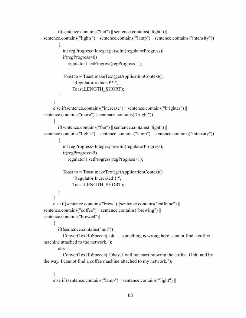
83
if(sentence.contains("fan") || sentence.contains("light") ||
sentence.contains("lights") || sentence.contains("lamp") || sentence.contains("intensity"))
{
int regProgress=Integer.parseInt(regulatorProgress);
if(regProgress>0)
regulator1.setProgress(regProgress-1);
Toast to = Toast.makeText(getApplicationContext(),
"Regulator reduced!!!",
Toast.LENGTH_SHORT);
}
}
else if(sentence.contains("increase") || sentence.contains("brighter") ||
sentence.contains("more") || sentence.contains("bright"))
{
if(sentence.contains("fan") || sentence.contains("light") ||
sentence.contains("lights") || sentence.contains("lamp") || sentence.contains("intensity"))
{
int regProgress=Integer.parseInt(regulatorProgress);
if(regProgress<5)
regulator1.setProgress(regProgress+1);
Toast to = Toast.makeText(getApplicationContext(),
"Regulator Increased!!!",
Toast.LENGTH_SHORT);
}
}
else if(sentence.contains("brew") ||sentence.contains("caffeine") ||
sentence.contains("coffee") || sentence.contains("brewing") ||
sentence.contains("brewed"))
{
if(!sentence.contains("not"))
ConvertTextToSpeech("oh. . . something is wrong here, cannot find a coffee
machine attached to the network.");
else {
ConvertTextToSpeech("Okay, I will not start brewing the coffee. Ohh! and by
the way, I cannot find a coffee machine attached to my network.");
}
}
else if (sentence.contains("lamp") || sentence.contains("light") ||
84
sentence.contains("bulb") || sentence.contains("lights") || (sentence.contains("dark"))) {
if (sentence.contains("so") || sentence.contains("too") || sentence.contains("on")
&& !sentence.contains("not")) {
boolean networkProblem=false;
try {
t = new Thread(new ClientThread());
t.start();
String str = HomeId+"01011";
PrintWriter out = new PrintWriter(new BufferedWriter(
new OutputStreamWriter(socket.getOutputStream())),
true);
out.println(str);
socket.close();
lamp1.setChecked(true);
lamp1.setBackground(lamp1_on_image);
ConvertTextToSpeech("The light is now on.");
if(!networkProblem) {
ConvertTextToSpeech("The light is now on.");
Toast to = Toast.makeText(getApplicationContext(),
"Light on!!!",
Toast.LENGTH_SHORT);
to.show();
}
}catch (Exception e) {
networkProblem=true;
ConvertTextToSpeech("There seems to be some problem connecting with the
network.");
e.printStackTrace();
}
} else if ((sentence.contains("off") || sentence.contains("out") ||
sentence.contains("no") || (sentence.contains("dont") &&
sentence.contains("need"))||
(sentence.contains("no") && sentence.contains("need"))))
//&& !sentence.contains("not"))
{
try {
t = new Thread(new ClientThread());
t.start();
85
String str = HomeId+"01010";
PrintWriter out = new PrintWriter(new BufferedWriter(
new OutputStreamWriter(socket.getOutputStream())),
true);
out.println(str);
socket.close();
ConvertTextToSpeech("There you go. The light is off.");
Toast to = Toast.makeText(getApplicationContext(),
"Light off!!!",
Toast.LENGTH_SHORT);
to.show();
lamp1.setChecked(false);
lamp1.setBackground(lamp1_off_image);
} catch (Exception e) {
ConvertTextToSpeech("Cannot connect with the network. Check your LAN
connection.");
e.printStackTrace();
}
}
}
}
public void addClickListener_toggleButton() {
lamp1.setOnClickListener(new View.OnClickListener() {
@Override
public void onClick(View v) {
// TODO Auto-generated method stub
if (lamp1.isChecked()) {
try {
t = new Thread(new ClientThread());
t.start();
String str = HomeId+"01011";
// Thread readThread=new Thread(new ReadFromServerThread(socket));
// readThread.start();
PrintWriter out = new PrintWriter(new BufferedWriter(
new OutputStreamWriter(socket.getOutputStream())),
true);
86
out.println(str);
//
Toast.makeText(getApplicationContext(),SERVER_IP,Toast.LENGTH_SHORT).show();
socket.close();
lamp1.setBackgroundDrawable(lamp1_on_image);
}catch (Exception e) {
lamp1.setChecked(false);
lamp1.setBackground(lamp1_off_image);
Toast.makeText(getApplicationContext(),"There is some problem
connecting to the device. Please check your
connection",Toast.LENGTH_SHORT).show();
e.printStackTrace();
}
} else {
try {
t = new Thread(new ClientThread());
t.start();
String str = HomeId+"01010";
// Thread readThread=new Thread(new ReadFromServerThread(socket));
// readThread.start();
PrintWriter out = new PrintWriter(new BufferedWriter(
new OutputStreamWriter(socket.getOutputStream())),
true);
out.println(str);
//
Toast.makeText(getApplicationContext(),SERVER_IP,Toast.LENGTH_SHORT).show();
socket.close();
} catch (Exception e) {
lamp1.setChecked(false);
lamp1.setBackground(lamp1_off_image);
Toast.makeText(getApplicationContext(),"There is some problem
connecting to the device. Please check your
connection",Toast.LENGTH_SHORT).show();
e.printStackTrace();
}
lamp1.setBackground(lamp1_off_image);
}
}
});
87
}
class ClientThread implements Runnable {
@Override
public void run() {
try {
InetAddress serverAddr = InetAddress.getByName(SERVER_IP);
socket = new Socket(serverAddr, SERVERPORT);
} catch (UnknownHostException e1) {
e1.printStackTrace();
} catch (IOException e1) {
e1.printStackTrace();
}
}
}
class ReadFromServerThread implements Runnable {
private Socket clientSocket;
private BufferedReader input;
public ReadFromServerThread(Socket clientSocket) {
this.clientSocket = clientSocket;
try {
this.input = new BufferedReader(new
InputStreamReader(this.clientSocket.getInputStream()));
} catch (IOException e) {
e.printStackTrace();
}
88
}
public void run() {
while (!Thread.currentThread().isInterrupted()) {
try {
String read = input.readLine();
// updateConversationHandler.post(new updateUIThread(read));
Toast to = Toast.makeText(getApplicationContext(),
read,
Toast.LENGTH_SHORT);
to.show();
clientSocket.close();
} catch (IOException e) {
e.printStackTrace();
}
}
}
}
}
TCPClient.java
package com.example.androidsocketclient;
/**
* Created by Mrunal
*/
import android.util.Log;
import java.io.BufferedReader;
import java.io.BufferedWriter;
89
import java.io.InputStreamReader;
import java.io.OutputStreamWriter;
import java.io.PrintWriter;
import java.net.InetAddress;
import java.net.Socket;
public class TCPClient {
private String serverMessage;
public String SERVERIP = "10.0.0.11"; //your computer IP address
public int SERVERPORT = 8080;
private OnMessageReceived mMessageListener = null;
public boolean mRun = false;
PrintWriter out;
BufferedReader in;
/**
* Constructor of the class. OnMessagedReceived listens for the messages received
from server
*/
public TCPClient(OnMessageReceived listener, String ip, int port) {
mMessageListener = listener;
mRun=false;
if(ip!=null && !ip.equals(""))
{
SERVERIP=ip;
}
if(port!=0)
{
SERVERPORT=port;
}
}
/**
* Sends the message entered by client to the server
* @param message text entered by client
*/
90
public void sendMessage(String message){
Log.e("Client: Data->", message);
if (out != null && !out.checkError()) {
out.println(message);
out.flush();
}
}
public void stopClient(){
mRun = false;
}
public void run() {
mRun = true;
try {
//here you must put your computer's IP address.
InetAddress serverAddr = InetAddress.getByName(SERVERIP);
Log.e("TCP Client", "C: Connecting...");
//create a socket to make the connection with the server
Socket socket = new Socket(serverAddr, SERVERPORT);
try {
//send the message to the server
out = new PrintWriter(new BufferedWriter(new
OutputStreamWriter(socket.getOutputStream())), true);
Log.e("TCP Client", "C: Sent");
Log.e("TCP Client", "C: Done.");
//receive the message which the server sends back
in = new BufferedReader(new InputStreamReader(socket.getInputStream()));
//in this while the client listens for the messages sent by the server
while (mRun) {
91
serverMessage = in.readLine();
if (serverMessage != null && mMessageListener != null) {
//call the method messageReceived from MyActivity class
mMessageListener.messageReceived(serverMessage);
Log.e("RESPONSE FROM SERVER", "S: Received Message: '" +
serverMessage + "'");
}
serverMessage = null;
}
} catch (Exception e) {
Log.e("TCP", "S: Error", e);
} finally {
//the socket must be closed. It is not possible to reconnect to this socket
// after it is closed, which means a new socket instance has to be created.
socket.close();
}
} catch (Exception e) {
Log.e("TCP", "C: Error", e);
}
}
//Declare the interface. The method messageReceived(String message) will must be
implemented in the MyActivity
//class at on asynckTask doInBackground
public interface OnMessageReceived {
public void messageReceived(String message);
}
}


