Blanca Mancilla
Intensional Infrastructure for
Collaborative Mapping
A thesis submitted in fulfilment
of the requirements for the degree of
Doctor in Philosophy
SCIENTIA
MANU E T MENTE
The University of New South Wales
School of Computer Science and Engineering
April 2004
c© Mancilla 2004
Abstract
This thesis presents the Anita Conti Mapping Server, a Web interface and in-
frastructure for the creation and presentation of maps using an active, pervasive,
multidimensional, global context. For each user, the context contains the param-
eterizations for every component of the system. In addition, parts of a user’s
context may be shared with other users, so that the actions of one user directly
affect the look, feel and content of another user’s system, thereby giving new
meaning to the term collaborative computing.
The mapping server consists of a Web interface, the GMT mapping tools, a
database and the Omega typesetting system. Instead of the components being
directly attached to each other through point-to-point communication, they are
brought together by the context. This approach provides much more flexbility,
since new components and new parameters can be more easily added to the overall
system, with little or no change to the components already present.
The whole infrastructure is built using intensional programming, a form of
programming in which software entities are considered to be intensions (in the
logical sense), i.e. mappings from contexts to ordinary entities, called extensions.
The thesis presents a comprehensive overview of the development of intensional
programming, and highlights its relevance for current work in the areas of elec-
tronic documents and distributed software configuration management.
The mapping server is the most significant intensional application to date:
it contains the most number of lines of intensional code ever written with the
biggest context space implemented in a real, working system.
The thesis focuses on the parameterization of the Web interface, the mapping
i
ii
engine and the generation of correctly typeset labels for maps to create a param-
eter space that accurately describes these components, and how this parameter
space as a whole can be browsed by a user independently or as a member of a
collaborative group.
This thesis is just the beginning of a new way to look at mapping and proves
that focusing on the context allows the creation of powerful extensible software.
Contents
1 Introduction 1
2 Around the World 9
2.1 Adaptive Web pages . . . . . . . . . . . . . . . . . . . . . . . . . 10
2.2 Terminology . . . . . . . . . . . . . . . . . . . . . . . . . . . . . . 16
2.3 Online mapping servers . . . . . . . . . . . . . . . . . . . . . . . . 19
2.4 The Anita Conti Mapping Server . . . . . . . . . . . . . . . . . . 30
3 The Essence 33
3.1 Intensional logic . . . . . . . . . . . . . . . . . . . . . . . . . . . . 35
3.2 Lucid and the rediscovery of intensionality . . . . . . . . . . . . . 39
3.3 Two-stage eduction . . . . . . . . . . . . . . . . . . . . . . . . . . 43
3.4 Intensional versioning . . . . . . . . . . . . . . . . . . . . . . . . . 43
3.5 Intensional documents and markup . . . . . . . . . . . . . . . . . 46
3.6 Programming with versions . . . . . . . . . . . . . . . . . . . . . 51
3.7 Intensional communities . . . . . . . . . . . . . . . . . . . . . . . 54
3.8 Distributed intensional programming . . . . . . . . . . . . . . . . 56
3.9 Intensional Web programming . . . . . . . . . . . . . . . . . . . . 61
3.10 Maps and intensionality . . . . . . . . . . . . . . . . . . . . . . . 63
4 Sharing the Context 65
4.1 Our intensional community . . . . . . . . . . . . . . . . . . . . . . 67
4.2 Collaborative mapping . . . . . . . . . . . . . . . . . . . . . . . . 68
4.3 The context space branches . . . . . . . . . . . . . . . . . . . . . 74
iii
Contents iv
4.3.1 The status branch . . . . . . . . . . . . . . . . . . . . . . . 75
4.3.2 The user branch . . . . . . . . . . . . . . . . . . . . . . . . 76
4.3.3 The æther branch . . . . . . . . . . . . . . . . . . . . . . . 80
4.4 Participants . . . . . . . . . . . . . . . . . . . . . . . . . . . . . . 81
4.5 Applet participant . . . . . . . . . . . . . . . . . . . . . . . . . . 83
4.6 Summary . . . . . . . . . . . . . . . . . . . . . . . . . . . . . . . 85
5 The Mapping Engine 86
5.1 An introduction to GMT and pscoast . . . . . . . . . . . . . . . 87
5.2 Projections . . . . . . . . . . . . . . . . . . . . . . . . . . . . . . 89
5.3 The region . . . . . . . . . . . . . . . . . . . . . . . . . . . . . . . 96
5.4 Map frame and grid . . . . . . . . . . . . . . . . . . . . . . . . . . 97
5.5 Colors . . . . . . . . . . . . . . . . . . . . . . . . . . . . . . . . . 100
5.6 Resolution . . . . . . . . . . . . . . . . . . . . . . . . . . . . . . . 101
5.7 Borders and lines . . . . . . . . . . . . . . . . . . . . . . . . . . . 101
5.8 Layers and layout . . . . . . . . . . . . . . . . . . . . . . . . . . . 102
5.9 Initial context . . . . . . . . . . . . . . . . . . . . . . . . . . . . . 103
6 Multilingual text and Maps 105
6.1 Adding labels to maps . . . . . . . . . . . . . . . . . . . . . . . . 106
6.2 The multilingual database . . . . . . . . . . . . . . . . . . . . . . 108
6.3 The geographical region . . . . . . . . . . . . . . . . . . . . . . . 111
6.4 Label placement . . . . . . . . . . . . . . . . . . . . . . . . . . . . 115
6.5 Multiparametric data . . . . . . . . . . . . . . . . . . . . . . . . . 116
6.6 Intensional SQL . . . . . . . . . . . . . . . . . . . . . . . . . . . . 118
6.7 Building a multiversion database . . . . . . . . . . . . . . . . . . 122
6.7.1 Versioned names . . . . . . . . . . . . . . . . . . . . . . . 122
6.7.2 Area versus point . . . . . . . . . . . . . . . . . . . . . . . 122
6.7.3 Tailored labels . . . . . . . . . . . . . . . . . . . . . . . . . 123
6.8 Moving beyond rectangles . . . . . . . . . . . . . . . . . . . . . . 124
Contents v
7 Context and Contents Displayed 126
7.1 The first attempt . . . . . . . . . . . . . . . . . . . . . . . . . . . 127
7.2 The actual thing . . . . . . . . . . . . . . . . . . . . . . . . . . . 128
7.2.1 The context space . . . . . . . . . . . . . . . . . . . . . . . 130
7.2.2 Multilingual Web pages . . . . . . . . . . . . . . . . . . . 131
7.2.3 Malleable pages . . . . . . . . . . . . . . . . . . . . . . . . 133
7.3 Building intensional page elements . . . . . . . . . . . . . . . . . 136
7.3.1 Menus . . . . . . . . . . . . . . . . . . . . . . . . . . . . . 137
7.3.2 Radio buttons . . . . . . . . . . . . . . . . . . . . . . . . . 138
7.3.3 Text input . . . . . . . . . . . . . . . . . . . . . . . . . . . 139
7.4 The Web page . . . . . . . . . . . . . . . . . . . . . . . . . . . . . 140
7.4.1 Menus in practice . . . . . . . . . . . . . . . . . . . . . . . 142
7.4.2 Multicase display . . . . . . . . . . . . . . . . . . . . . . . 143
7.4.3 Checking for textual input . . . . . . . . . . . . . . . . . . 146
7.4.4 Two-way toggle . . . . . . . . . . . . . . . . . . . . . . . . 148
7.4.5 Three-way toggle . . . . . . . . . . . . . . . . . . . . . . . 149
7.5 Clickable maps . . . . . . . . . . . . . . . . . . . . . . . . . . . . 154
7.6 Summary . . . . . . . . . . . . . . . . . . . . . . . . . . . . . . . 155
8 The Future of Internet Mapping 156
8.1 Contributions . . . . . . . . . . . . . . . . . . . . . . . . . . . . . 156
8.2 Interface improvements . . . . . . . . . . . . . . . . . . . . . . . . 157
8.3 Developing new functionality . . . . . . . . . . . . . . . . . . . . . 158
8.3.1 Map related functions . . . . . . . . . . . . . . . . . . . . 158
8.3.2 Intensionality . . . . . . . . . . . . . . . . . . . . . . . . . 159
8.4 Getting the data . . . . . . . . . . . . . . . . . . . . . . . . . . . 160
Bibliography 161
List of Figures
2.1 Example of a version space in tree form. . . . . . . . . . . . . . . 14
2.2 WaitingImage is pointed from and points to many pages . . . . . 15
2.3 The links of all the pages are generated on the fly . . . . . . . . . 15
2.4 Microsoft Encarta’s online atlas . . . . . . . . . . . . . . . . . . . 20
2.5 Input form of the OMC (Online Map Creation) . . . . . . . . . . . 23
2.6 Result of pressing Create Map in Figure 2.5 . . . . . . . . . . . . 24
2.7 NASA Web map viewer . . . . . . . . . . . . . . . . . . . . . . . . 26
2.8 Default values of initial page . . . . . . . . . . . . . . . . . . . . . 31
2.9 The updated map after all the changes . . . . . . . . . . . . . . . 32
3.1 Class hierarchy of libintense . . . . . . . . . . . . . . . . . . . . . 60
4.1 The intensional community of the Anita Conti Mapping Server . . 67
4.2 Branch types of the context space . . . . . . . . . . . . . . . . . . 69
4.3 Workflow of JSP pages for the Sharing option . . . . . . . . . . . 70
4.4 Main or entry Web page of the mapping server . . . . . . . . . . . 71
4.5 Collaboration options of the user . . . . . . . . . . . . . . . . . . 72
4.6 Input of new æther information . . . . . . . . . . . . . . . . . . . 73
4.7 Main Web page of an “owner” user . . . . . . . . . . . . . . . . . 73
4.8 Main Web page of a “listener” user . . . . . . . . . . . . . . . . . 74
4.9 The status branch . . . . . . . . . . . . . . . . . . . . . . . . . . . 75
4.10 The user branch . . . . . . . . . . . . . . . . . . . . . . . . . . . . 77
4.11 The info branch of the user type branch . . . . . . . . . . . . . . 77
4.12 The ætherId branch of the user branch . . . . . . . . . . . . . . . 79
vi
List of Figures vii
4.13 The æther branch . . . . . . . . . . . . . . . . . . . . . . . . . . . 80
4.14 Applet with listener thread to node A1:interface . . . . . . . . . . 84
5.1 Abridged syntax of pscoast . . . . . . . . . . . . . . . . . . . . . 88
5.2 The GMT version space . . . . . . . . . . . . . . . . . . . . . . . . 89
5.3 Projection version space . . . . . . . . . . . . . . . . . . . . . . . 93
5.4 The projectionClass expanded . . . . . . . . . . . . . . . . . . . . 94
5.5 Region version space . . . . . . . . . . . . . . . . . . . . . . . . . 96
5.6 The context space corresponding to the -B option . . . . . . . . . 99
5.7 The version space to set the color of the map . . . . . . . . . . . . 100
5.8 The version space of -D, -W, -I and -N switches . . . . . . . . . . 101
5.9 PostScript layers using -K and -O . . . . . . . . . . . . . . . . . . 103
5.10 Initial context for a user for gmt branch . . . . . . . . . . . . . . 104
6.1 Table langs of database Worldnames . . . . . . . . . . . . . . . . 108
6.2 Table location of database Worldnames . . . . . . . . . . . . . . 109
6.3 Cross-section of tables english, espanol and francais . . . . . . 110
6.4 Possible map region span (in longitude) . . . . . . . . . . . . . . . 112
6.5 Region spread not needing transformation . . . . . . . . . . . . . 113
6.6 Transformation from region a to a′ . . . . . . . . . . . . . . . . . 113
6.7 Transformation from region b to b′ . . . . . . . . . . . . . . . . . . 113
6.8 Examples of class1 . . . . . . . . . . . . . . . . . . . . . . . . . . 114
6.9 Examples of class2 . . . . . . . . . . . . . . . . . . . . . . . . . . 115
6.10 The future intensional community of the server . . . . . . . . . . 124
7.1 JSP scripts for Web page production . . . . . . . . . . . . . . . . 130
7.2 The version space of GUI . . . . . . . . . . . . . . . . . . . . . . . 131
7.3 Top main Web page . . . . . . . . . . . . . . . . . . . . . . . . . . 134
7.4 Default values of initial page . . . . . . . . . . . . . . . . . . . . . 141
7.5 Zoom of Figure 7.4 (Part I) . . . . . . . . . . . . . . . . . . . . . 141
7.6 Change of projection . . . . . . . . . . . . . . . . . . . . . . . . . 144
7.7 Zoom of Figure 7.4 (Part II) . . . . . . . . . . . . . . . . . . . . . 148

List of Figures viii
7.8 Change of map frame and color . . . . . . . . . . . . . . . . . . . 148
7.9 Zoom of Figure 7.4 (Part III) . . . . . . . . . . . . . . . . . . . . 151
7.10 Changes from Figure 7.9 . . . . . . . . . . . . . . . . . . . . . . . 151
7.11 The updated map after all the changes . . . . . . . . . . . . . . . 153
List of Tables
4.1 Font conventions for dimension and dimension values . . . . . . . 69
5.1 Description of GMT projections . . . . . . . . . . . . . . . . . . . 90
5.2 Projections classified . . . . . . . . . . . . . . . . . . . . . . . . . 93
6.1 Identification codes for entities in Worldname . . . . . . . . . . . . 109
ix
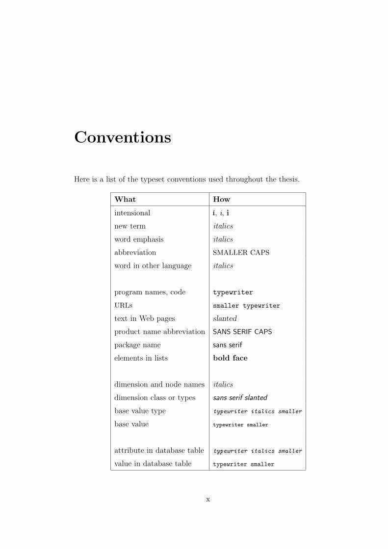
Conventions
Here is a list of the typeset conventions used throughout the thesis.
What How
intensional i, i, i
new term italics
word emphasis italics
abbreviation SMALLER CAPS
word in other language italics
program names, code typewriter
URLs smaller typewriter
text in Web pages slanted
product name abbreviation SANS SERIF CAPS
package name sans serif
elements in lists bold face
dimension and node names italics
dimension class or types sans serif slanted
base value type typewriter italics smaller
base value typewriter smaller
attribute in database table typewriter italics smaller
value in database table typewriter smaller
x
Chapter 1
Introduction
In the beginning there was
Intensionality
This thesis presents a radically new and practical infrastructure for developing
collaborative environments on the Web. This infrastructure is illustrated through
the creation of an online geographical mapping tool that incorporates a geograph-
ical map maker, a high-quality multilingual typesetter and an innovative model
for a database system to store multiple versions of multilingual text.
The key innovation is the use of a tree-structured context that pervades the
entire infrastructure and allows the different components of the system to come
together in a natural way. The paradigm used is called intensional programming :
a program is an intension, a mapping from contexts to ordinary programs. The
context includes the full parameterization of every software component as well as
all of the user profiles. The context is active, so if parts of the context are shared
by several users, each user’s view of the infrastructure adapts spontaneously.
But the context does more than just allow users to keep track of the paramete-
rizations of the infrastructure’s components. Each component, no matter how
large or how small, itself becomes much richer because it adapts to a changing,
multidimensional context. This adaptation applies to programs, to documenta-
tion, to user interfaces, and even to data!
1
Chapter 1. Introduction 2
The context is also the heart of any collaboration between users. Different
users can register themselves to follow changes or to modify values of certain
parts of one or more global contexts, thereby allowing themselves to share their
activities with other users registered as participants in any of the these contexts.
The Anita Conti Mapping Server, developed for this thesis, is a fully working
example of such a collaborative infrastructure based on a pervasive context. Using
the context, it brings together disparate applications and remote users to work
as a group and produce multilingual maps. Initially, the goal of this thesis was to
produce versioned maps: maps that are produced in different versions depending
on a changing context. In developing the system, I realized that to produce
versioned maps I needed to also create a supporting infrastructure. I needed to
provide an intensional interface; a multilingual database with appropriate APIs;
and a collaborative platform, for users to share their versioned maps.
To choose maps as the content of the most significant intensional application
to date is not a random choice. The content of a map is some geographical region,
itself a context, along with other features. As a result, content and context can
intermix freely.
In the Anita Conti Mapping Server, a map is represented by a set of parame-
ters, called dimensions and stored in a central repository, shared among the users
who need them. These dimensions are too numerous, with structures too complex
to list here. They are the subject of several sections throughout the text.
Maps are particularly interesting from the point of view of formal parameter-
ization, since the resulting parameter space is too large to manually manipulate
in its entirety.
Using intensional programming, programs can adapt their behavior to a per-
meating context, creating different output for different contexts. Intensional pro-
grams can in turn modify the context and make other programs aware of the
changes. It is natural to produce maps using this framework: It provides a pro-
grammable way to manipulate (probe, change, pass around, split and reunite) the
parameter space to produce the requested version of the map. Once a context is
built and programs for map creation are developed, it is straightforward to share
Chapter 1. Introduction 3
this context with other applications, and in doing so, broadcast the parameter
space of the mapping tool to the entire system, informing all other components of
its status. At the same time, other parameterized applications can make available
their own parameter space through the context, sharing their space, resulting in
all the applications having a common ground. With it, they can freely commu-
nicate and synchronize their actions to become a coherent system.
By systematically using the context and intensional programming, I have de-
veloped a complex working infrastructure that deals with different aspects of
computing, bringing different heterogeneous entities together to form one system
to work towards a common goal. With this infrastructure, I have succeeded in
providing new insights into the following four fundamental questions in comput-
ing. My answers allow generalized solutions to each question as well as an overall
approach for building a system that must bring the different pieces together.
How do we store and retrieve things? The base of any software system is
the data being manipulated. To store this data requires some form of file system
or database. But what happens if the data is itself context-dependent, and the
set of possible contexts cannot be fully enumerated because new parameters may
appear as the system evolves? In this dynamic scenario, how can one develop
efficient means for storing and retrieving data, without forcing massive periodic
reconfigurations of the storage infrastructure?
How do we run things? Most software systems are made of several pro-
grams or applications. Depending on the needs of a user at a given instant, only
a subset of these programs will be used, and these will need to be configured so
that they can interact correctly with the given input. Typically this setup is done
using a combination of configuration files and environment variables. But what
happens if this setup must continually change as a user’s needs change? Worse,
what happens if the total set of programs itself grows or varies over time? What
happens if this process is not simply driven by user preferences but also by the
nature of data streaming in real time? How does one ensure that the system
reconfigures itself as the needs change?
Chapter 1. Introduction 4
How do we view things? For modularity reasons, graphical user interfaces
(GUIs) are commonly built separately from the applications whose results they
are presenting. As a result, GUIs often end up limiting or highly constraining
access to the underlying functionality. These problems are even worse if this
functionality is itself highly flexible and dynamically reconfigurable, as data and
user needs change. How does one build context-sensitive interfaces, that mold
themselves to user needs? How should an interface indicate to the rest of the
system that it should adapt to context changes and, in turn, how should it present
the underlying system’s reconfiguration? When multiple users are interacting
through the system, how can the interface enable and illustrate this interaction?
How do we share things? In this age of permanent network access, it is
a given that users can interact through software systems in myriad ways. For
the most part, this interaction takes place through email, chat rooms and file
sharing. But this interaction should go much further, because sharing does not
only happen at the user level. How do components, radically different in nature
and design, share information and data, and synchronize their actions? How
can a user follow the actions of a group or of users doing different things, at an
arbitrary level of detail? How can one take advantage of these possibilities so
that users can collaborate and produce collective results?
This thesis answers all of these questions with a simple solution: “Use the
context”. The context is brought explicitly to the fore, and components are
joined simply by sharing the context.
Chapter 2 presents an overview of existing Web mappers, explaining how the
lack of an explicit context significantly impedes their utility. An overall view of
the Anita Conti Mapping Server is given at the end of the chapter, in order to
contrast the intensional approach with that of existing tools.
Chapter 3 gives a complete overview of intensional programming and inten-
sional versioning, key to the manipulation of the context. The chapter opens with
an extensive overview of the beginnings of intensional logic, dating back to Aris-
totle. It then connects intensional logic and intensional programming, leading
Chapter 1. Introduction 5
naturally into previous work by focusing on intensional documents. It introduces
libintense [1], a library implemented for both Java and C++ for the development
of context-aware programs. This chapter allows the reader to better understand
the following chapters, as well as how the different parts fit together.
The core of the thesis (Chapters 4–7) presents the components of the Anita
Conti Mapping Server: collaboration, Web interface, geographical mapping tools,
typesetter and database, summarized below.
Chapter 4 explains how collaboration and sharing take place via the context.
If there is a global context akin to the atmosphere, each component has a local
context akin to the microclimate that animate beings carry around them. A
change of one of these local contexts can provoke changes in the global context, in
turn provoking changes in the local contexts of other components. This happens
when there are intercontextual parameters, or parameters that appear in different
local contexts, and a change in one of them has side effects, changing all of them.
Explicit collaboration takes place by components keeping track of changes in
the local contexts of other, specific components. In the case of the Anita Conti
Mapping Server, I have created a context sharing infrastructure that allows users
to publish the part of their local context that controls the configuration of their
user interface and of the underlying mapping software. Users can pick up only
the changes that interest them for their own context. In doing so, users can work
together to produce interesting maps while still retaining personal profiles; they
can share as much or as little as they want.
The Web interface, presented in Chapter 7, is a family of Web pages, each
of which is context-dependent. Each page is generated as needed, on demand,
using values in the context. This process includes link generation: a relative link
points to the correct version of the page in accordance to the current context.
These parameters can be modified at any point provoking the production of a
new page, with the correct links.
We call these pages multidimensional and this Web infrastructure is imple-
mented using a software package that combines JSP (Java Server Pages) and
libintense. The new package is called ijsp (intensional JSP). Chapter 7 shows how
Chapter 1. Introduction 6
the contents (i.e., the parameters) of maps and multilingual labels are presented
to the user and how this context can be modified.
The mapping server uses the GMT suite of mapping tools [2] for map making,
tools accessed through the command line in most operating systems. Configu-
ration and running of these tools is done through a plethora of command line
arguments and configuration files, the latter actually being changed by the ac-
tions of these tools. Using these tools for an online, multiuser context sharing
infrastructure is a non trivial process. Chapter 5 explains how GMT is integrated
into the Anita Conti Mapping Server.
We have focused our attention on the pscoast command, which produces
outlines for the world’s coastlines, major river systems and major political bound-
aries. These outlines can be produced for all (close to 30) of the two-dimensional
standard projections of the globe. Each of these projections can take many differ-
ent, separate arguments. By inserting pscoast into a context-dependent wrap-
per, a user can easily keep track of hundreds of parameters in the context itself
and can instantly switch from one projection to another, with the context keep-
ing track of the personal preferences for each of the projections. Moreover, the
Web interface itself adapts to this part of the context, thereby offering a more
user-friendly interface as needed.
Chapter 6 explains the problem of putting geographical place labels onto a
map. Since the goal of the Anita Conti Mapping Server is to produce maps of
any part of the world in any language, the maps are labelled using Ω (the Omega
Typesetting System [3]), a generalization of TEX built for high quality typesetting
of all the world’s languages. Ω does not simply typeset text in a given language.
For a given language or script, there may be dozens of parameters needed for fine
control of the typeset output. This problem is somewhat more complicated than
controlling pscoast, because the set of languages is not bounded. Languages
evolve and take new forms. Exact parameterization of these changes requires
careful study of indivudual cases and sometimes approximatations are the best
solution.
Chapter 1. Introduction 7
But even when the language has been specified, Ω needs the strings to typeset
and a location to place them, parameters that are all context dependent. These
strings represent geographical names and storing them is by no means the least
of the problems.
A city, for example, might have numerous names, translations and spellings,
in different languages, through time, space and culture. Since the parameters of
the variants cannot be fully enumerated, it becomes very difficult to efficiently
store and retrieve these names. We have designed iSQL, Intensional SQL, which
allows the storage of context dependent data. In this extension of SQL, relations,
records and values may all vary with the context.
This powerful collaborative infrastructure could only be developed by focusing
on the context. It is a dynamic, reactive entity, programmable through intensional
programming, bringing the whole system together. Without the context, collab-
oration would simply be file and memory sharing. The context is the medium for
interactions between the components and users of the system.
The Anita Conti Mapping Server was named during my visit to the Ecole
Nationale Superieure des Telecommunications, ENST-Bretagne, from April to
July 2002, in France. While there, my daughters attended the public school in
Plouzane which was changing names from Ecole Publique de La Trinite, to Ecole
Publique Anita Conti. Intrigued, I decided to look into this woman’s biography
at the time that I was looking for a name for my mapper.
Anita Conti (1899–1997) was known as La Dame de la Mer or the Woman
of the Sea. She was the first woman oceanographer in a time when the sailing
world was reserved for men. She sailed the oceans in any available ship to study
the ocean floors, to build fishery charts of different parts of the Atlantic Ocean,
to record water temperatures and salinity levels, and, in her spare time, to pho-
tograph aspects of the lives of mariners. Her fascination for her work and for
the sea made of her the first woman to survive le Grand Metier, as sailing is
commonly known. She only stopped sailing in her early eighties, concerned with
human abuse of the oceans.

Chapter 1. Introduction 8
Her life is an inspiration to my work. Her goal was to disseminate knowl-
edge about the ocean and the human relations it encompasses. The Anita Conti
Mapping Server’s goal is to disseminate knowledge, about the Earth, about the
relationship between oceans and lands, about the people, the inhabitants of the
Earth. Communities of people have spent their entire life searching and collecting
such knowledge. It is the knowledge of the human community, and it must be
returned to them.
What is presented in this thesis is only the beginning of the process of knowl-
edge dissemination. Much still needs to be done, much needs to be formalized
and generalized. This is evident in the concluding chapter, which presents many
future research and development projects.
Chapter 2
Around the World
The medium is the message
As was presented in the introduction, the Anita Conti Mapping Server aims
to demonstrate that sophisticated Web interfaces can be produced to interact
with the most complex mapping software, without in any way compromising the
control of this software or the level of quality of the end results.
This overall objective can better be understood by examining the arguments
of White [4], who claims that the production of generally accessible atlases has not
benefited from the introduction of new technologies, but, rather has impoverished
even the quality of printed maps. According to White, quality electronic atlases
are costly to the general population, both because of software licenses and the
expertise needed to run them, while free electronic maps do not always have freely
available data sets or mapping software. Meanwhile, the demand for printed
atlases is plunging, thereby making it more expensive to produce them. The
people who can afford the best quality mapping are most likely to move from
the paper map (static) to the digital world (more adaptable), leaving the printed
atlas demand depleted. So not only is it hard to produce good electronic maps
but good quality printed maps are becoming less affordable.
For sophisticated users, who wish to push the limits of visualization of geo-
referenced spatial and temporal data, trying to infer patterns, structures and
meaning from data [5], developing interfaces is a daunting task.
9
Chapter 2. Around the World 10
As an example, Furhmann [6], specifically working with hydrological mapping,
believes that standard GIS (Geographical Information System, see p.17) are not
suitable for developing full interactive geovisualization tools. Existing systems
simply cannot provide sufficient functionality in database management, graphical
interfaces and interactive or dynamic visualization techniques.
Uhlenkuken et al. [7] states that to undertake exploratory visualization, an
open system architecture, where different applications exchange data and meth-
ods, is required. However, most systems created are stand-alone tools, incapable
either of communication or of exchange. This is especially true of commercial
software, where the user is forced to use the application as a black box, only con-
cerned with the inputs and outputs, unable to modify the applications according
to their needs.
These authors agree that existing mapping tools do not fulfill the needs of
the research community. They focus both on a general lack of functionality and
adaptability, as well as on inappropriate user interfaces and APIs.
In designing the Anita Conti Mapping Server, we have taken a different ap-
proach, since we believe that the problems cannot simply be summarized as a
lack of functionality or clear interfaces but, rather, the lack of a context pervad-
ing through the activities of all the components of the system.
The chapter introduces the Anita Conti Mapping Server, after a discussion of
what a general-purpose online mapping server should look like, both at the Web
interface level and the functionality provided. It begins with a presentation of the
difficulties in building adaptive Web pages, and how intensionality supports this
process (§2.1). After an overview of terminology (§2.2) and existing Web mapping
servers (§2.3), the general functionality and snapshots of the Anita Conti Mapping
Server are presented (§2.4).
2.1 Adaptive Web pages
The advent of the Web has provided a standard infrastructure allowing anyone
to have an interface to any remote site. As a result, it has become natural to
Chapter 2. Around the World 11
expect that there should be a Web interface to every piece of software, no matter
how complex it might be. The difficulty with this expectation lies in the fact that
the Web protocol http is stateless, hence setting up persistent sessions is not a
natural process.
These difficulties are exacerbated if one wishes to create an adaptive Web
page, whose appearance changes according to user requests as well as to the
general hardware and software environment of the user. As these settings — the
environment — change, so should the page, with each part adapting itself to the
new settings. Absolute links to other Web pages should not change, while relative
links to related pages on the same site should somehow keep track of the settings
so they are not reset upon entering each new page.
To illustrate what an adaptive Web page does, consider the following simple
example. A multilingual Web site features five languages (English, French, Chi-
nese, Farsi and Spanish), with three types of text level (summary, normal and
full) and ten choices of color scheme for four pages enquiry, result, choice and
finish. These pages fully express the capabilities of the system and the user
can easily use its functionality. Each of the loaded pages adjusts itself to the
hardware of the machine (type of screen, internet link speed) and the software
available (browser).
When a user enters the Web site, she invokes the enquiry page, which is
loaded using default values (say, English, full text and blue–white, using Mozilla
on a high resolution screen with a high-speed cable modem). She requests a
different language and color scheme (Chinese and red–black), which makes the
enquiry page change. After submitting the query, a result page is presented
in Chinese, full text and red–black, values that will be maintained throughout,
unless changed by the user again. All the other pages, when requested, are
displayed with these settings.
This user then invites another user for shared browsing where the Web page
features are shared between the two browser windows. The users can share the
whole space or just certain aspects (e.g., language and color for appearance).
They can also decide on only one leader (the one who makes the decisions) or
Chapter 2. Around the World 12
jointly decide on the page features and the flow. For the latter, the infrastructure
provides protocols for turn taking.
We briefly consider three standard methods that might be used to implement
such a Web site, each only offering partial solutions.
Cloning-and-editing. For each of the four pages, a master page is taken (say
enquiry.html in English, with summary text, blue–white background),
and it is duplicated as many times as there are languages, and then edited
to translate the relevant chunks. Once this is done, all the created pages
are again duplicated for normal and full text. And the process continues to
cover all of the color schemes.
As described, this method is cumbersome. Adding a new feature means
adding a whole series of pages and editing manually. In fact simple main-
tenance becomes a major task since every single one of the pages must be
edited to propagate the most trivial change. As a result, sites maintained
in this manner often contain out-of-date or missing pages.
The major difficulty here is maintaining link consistency: how are relative
links, between pages in the same language, or between different language
and versions of the same page, to be maintained? It is not clear what should
happen when the page in the requested language does not exist. From the
user’s point of view, the requested page should be loaded in the default
language and the system should remember the requested language when
loading the next page.
Frames offer a partial solution to the problem of link consistency. Frames di-
vide Web pages into multiple, scrollable, independent regions. One frame
contains static information that the user must always see, while the others
show the dynamic information. The major drawback however is that the
fixed frame is hard coded and barely extensible.
To implement the above example, the fixed frame would contain the vari-
ables modifying the look of the page. However, these links are hardcoded
Chapter 2. Around the World 13
to static pages, so if one feature is changed, the flow is lost, starting anew
from entry point. This means that if in the choice page the user changes
the language, the enquiry page in the new language is loaded losing any
settings and data. From a conceptual point of view, the user is forced to
browse along through tree paths where the enquiry page is the root node.
Users make all the choices at the root and the browsing path is chosen.
When changing a parameter, the user must go back to the root and follow
a different path. There is no mechanism to deal with this problem, which
comes down to being able to jump across branches.
Dynamic Web pages form an alternative solution that addresses some of the
above issues. In this approach, pages are generated on demand by a script.
The advantage is the use of decision blocks to create pages: Decisions about
contents can be made on the fly. This approach is more flexible and new pa-
rameters can be added by modifying the script. Nevertheless, without the
use of a multidimensional context, the number of variants that can be han-
dled explicitly is limited, as the script can quickly become unmaintainable
with more and more explicit tests.
To fully implement the presented example with any of the above approaches
and without using a context would require massive work, yet none of the solu-
tions would be optimal, simply for a page being browsed by a single user. As
for a page being co-browsed by several users, none of the approaches offers any
relevant methods for even simple sharing, let alone for more elaborate forms of
collaboration. Dynamic pages might be programmed to support a primitive shar-
ing protocol, but again, without the context, Web programming is cumbersome,
due to the stateless nature of the communication protocols.
Using the context and intensional programming simplifies the programming of
dynamic Web pages. The entire set of pages is viewed as a single multidimensional
entity and, using intensional scripts, pages are generated on-demand based on the
dimension space of the page. To parameterize the above example (i.e., to create
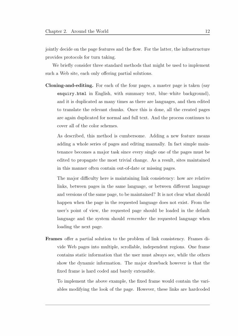
the dimension space), we define a tree-structured context, whose branches are the
Chapter 2. Around the World 14
dimensions appearance and settings. and subbranches level, language and color
under appearance, and browser , screen and linkSpeed under settings. Figure 2.1
summarizes this context and shows the possible values for each dimension.
root
appearance
levelsummary
normal
full
languageEnglish
French
Chinese
Persian
Spanish
color
background[value ]
text[value ]
settings
browsermozilla
netscape
explorer
safari
screen1280 x 1024
1152 x 768
1024 x 768
1280 x 854
896 x 600
800 x 600
720 x 420
640 x 480
other
linkSpeedslow
normal
fast
Figure 2.1: Example of a version space in tree form.
The context is changed using a context operation (Chapter 3, §3.8, p.58),
which selectively modifies the values associated with designated dimensions. Be-
low is a context operation that completely replaces the current context:
[appearance:[level:[summary]+
language:[English]+
color:[background:[pink]+text:[blue]]]+
settings:[browser:[mozilla]+
screen:[1024 x 768]+
linkSpeed:[slow]]]
The script — written using intensional languages — probes the context and,
using values from the latter, generates the correct content for each part of the
page, and displays the context values for user update. The page is then ready for
another cycle. The user may change the look of the page or make a server query.
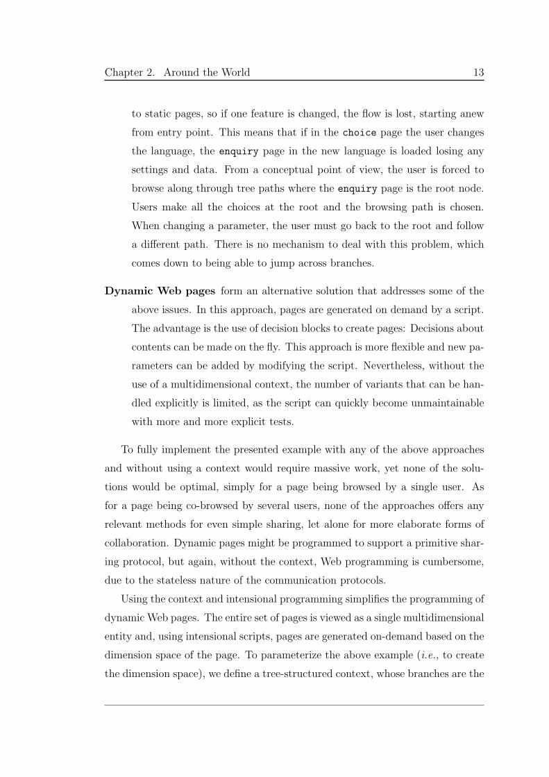
In addition, intensionality helps solve the problem of multiple versions of
the same page pointing to an unversioned page, the latter pointing to another
versioned page. Unless the resource knows which version of the resulting page to
Chapter 2. Around the World 15
point to, it can only point to a default page, losing previously chosen preferences.
Figure 2.2 shows different versions of the enquiry page all pointing to a shared
WaitingImage page. This page is supposed to point back to the correct version
of the result page, but it is unclear how this should be done.
enquiryE
enquiryD
enquiryC
enquiryB
enquiryA
WaitingImage
resultE
resultD
resultC
resultB
resultA
Figure 2.2: WaitingImage is pointed from and points to many pages
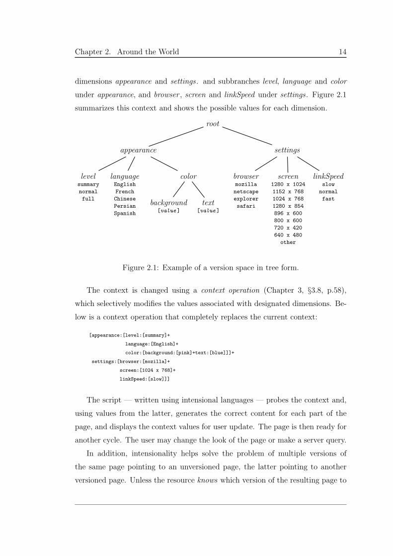
Using the context, the problem is easily solved. The enquiry page is generated
dynamically, according to the context, and its hyperlinks are version-dependent.
One of these links is to the correct version of the WaitingImage page, which will
itself be generated on the fly with the correct versioned hyperlink to the result
page. Each of the links in the generated pages points to a member of a family of
pages; the exact generated page depends on the context (Figure 2.3).
Dynamically
generated
enquiry
Dynamically
generated
WaitingImage
with versioned
links
Generated
result
based on
the context
Figure 2.3: The links of all the pages are generated on the fly

Chapter 2. Around the World 16
2.2 Terminology
There are two main types of software tools for cartographic visualization, i.e.,
tools that display some sort of map on a client screen. Offline tools offer services
to users on standalone workstations or sharing a Local Area Network (LAN),
sharing a file system and other system resources. Online servers are remotely
accessible, usually over the Internet as a Web application. The online servers
contain a cartographic offline tool as mapping engine, whose effective function-
ality depends on the user interface. It is this type of tool that is freely available
and will be examined in this chapter. After the summary of online servers found
over the Internet at the time of writing, the chapter will finish with a detailed
description of the Anita Conti Mapping Server, the online server developed for
this thesis. The offline tool is GMT, introduced and explained in Chapter 5.
Several attempts to produce Web-based tools to display geographical maps
across the world are being made, offering a variety of interfaces, functionality
and visualization capabilities to the user. The variety is so vast that Rinner [8]
classifies these tools in the following categories:
1. Geodata servers allow the user to download geographical data (i.e., geo-
data) for postprocessing. It is up to the user to have the necessary tools
to achieve interesting results. In other words, these are servers that offer
geographical databases for downloading. They usually have limited visual-
ization capabilities.
2. Map servers enable visualization of geodata in the form of maps with
simple map functions such as zoom and pan. Rinner makes a weak distinc-
tion between static and interactive map servers: browsing through prepared
sets of maps (in this thesis called electronic atlases) versus choosing two or
three visualization parameters to create a map based on server-side pro-
cessing and client-side display.
Chapter 2. Around the World 17
3. Online retrieval systems add thematic map and simple retrieval func-
tions. Thematic mapping is the presentation of spatially referenced at-
tribute data on maps. They show the distribution of a single geographical
attribute (e.g., vegetation type or birth rate) or the relationship between
several attributes. Adding thematic functionality to a server simply means,
to allow the user to manually choose another database to map alternatively
or simultaneously.
4. Online GIS offer access to remote GIS functions and data. GIS function
servers allow full GIS operability on the user’s uploaded data or allow GIS
functions to be downloaded for local processing. These kind of servers
require the user to provide his own datasets (the uploaded data) or to own
software (functions for local processing) linked to a GIS application.
Rinner distinguishes servers of type 4 in two different categories. Here they
are collapsed into one, since they focus on GIS functionality as opposed to a
general mapping tool.
A GIS or Geographical Information System, is mapping software that links
information about where things are, with information about what things are like.
This information is structured into layers to create the map [9]. GIS technology
integrates, manipulates and displays a wide range of information to create a
picture illustrating, say, how socio-economic characteristics vary with geography.
The picture or map is created by integrating graphic and textual information
from separate databases. The function of this map is to support decision making
and problem solving [10]. Practitioners also regard the total GIS as including
operating personnel and the data that go into the system [11]. Complete GIS
systems are usually associated with proprietary software such as ArcInfo [12],
MAPublisher [13] and MapInfo [14], all very costly to the ordinary user due to
software licenses, required hardware and level of expertise for correct operation.
The main difference between a GIS and a mapping tool is that the first one
focuses on analysis and processing of data, including hidden databases, while the
second one focuses on mapping and display.
Chapter 2. Around the World 18
According to Rinner’s classification, the Anita Conti Mapping Server is an
interactive map server (type 2): it shows the user a map of a specified location
determined from the user’s inputs. GIS support (type 4) is envisaged as a future
project by adding a GIS application, such as GRASS [15]. A future project would
be to use servers of type 1 and with the downloaded datasets to convert the server
into a type 3 (Chapter 8).
The workflow of a general purpose online server (or Web server) is:
1. A request is made to the server for the introductory page of the server.
2. The user enters a request using this page and sends it back to the server.
3. The server processes the request and sends back a new result page.
4. The user is presented with the result and a form for further requests.
In this thesis, online map servers (type 2) are subdivided into two types,
according to their server-side processing (part (3) of the workflow). Electronic
Atlases hold precalculated maps, and the server-side processing is simply looking
through catalogues to retrieve the appropriate image file. The server-side pro-
cessing of Mapping Servers consists of building a map according to the requests
made by the user.
This division gives a more complete definition of type 2 servers than that
given by Rinner in his classification of Web tools for geographical mapping. The
distinction between static and interactive map servers is made clear here and is
crucial for the work presented in this thesis. The nature of the problems and the
solutions are completely different. Atlases require a fixed number of parameters
from the user and then effect a search in a catalog. Mapping servers require the
parameters to be processed and the correct database/mapping tool combination
to be called to produce the map for display.
In short, real interactive mapping servers consist of more than simply choosing
parameter values: they allow the user to decide about the entire environment to
create a map. In our approach, the environment is subsumed by the context,
which can be personalized, shared, passed around and logged.
Chapter 2. Around the World 19
2.3 Online mapping servers
Below is an overview of the two types of Web mapping servers: electronic atlases
and mapping servers.
Atlases
Atlases were the first attempt to make publicly available on the Internet huge
amounts of data about the Earth (maps, datasets, images, pictures). The imple-
mentation of the atlas server focuses on efficient graphical interfaces, reasonable
response time and options to search for additional data. The search is limited
to a fixed set of precalculated maps, effectively creating a map basement, beyond
which maps cannot be zoomed ; no new database can be plotted, and all of the
map parameters are fixed. The electronic atlases listed below constitute a conser-
vative summary; the purpose of the survey is to present what are the capabilities
of such servers.
• GlobeXplorer Image Viewer is a catalogue of satellite images and aerial
photography of certain regions of the world. Where both sets of data are
available and users are zooming into a region, the display is automatically
switched from satellite to airborne images at the correct scale, showing more
detail when needed. This trick gives amazing visual effects. However, the
system is unable to warn the user of incomplete or unavailable data, or to
offer the next best map available. Also, after a few cycles, the labels get
mixed, labelling an image as high resolution (house zooming level), when
displaying a satellite image of lower resolution (region zooming level).
http://www.globexplorer.com/cfviewer/viewer.cfm1
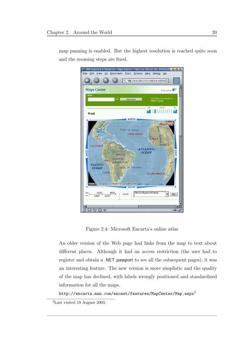
• Microsoft Encarta’s online atlas (snapshot in Figure 2.4) is a set of
maps starting from world scale up to region level, allowing the user to
browse using clickable maps through continents, sections of continents and
countries. Regions can also be accessed through a drop-down menu, and
1Last visited 20 June 2002.
Chapter 2. Around the World 20
map panning is enabled. But the highest resolution is reached quite soon
and the zooming steps are fixed.
Figure 2.4: Microsoft Encarta’s online atlas
An older version of the Web page had links from the map to text about
different places. Although it had an access restriction (the user had to
register and obtain a .NET passport to see all the subsequent pages), it was
an interesting feature. The new version is more simplistic and the quality
of the map has declined, with labels wrongly positioned and standardized
information for all the maps.
http://encarta.msn.com/encnet/features/MapCenter/Map.aspx2
2Last visited 19 August 2003.
Chapter 2. Around the World 21
• MapQuest’s most interesting feature is to allow the user to map an area
of a city from an entered address. Mostly data from the USA and Canada,
a user can also get directions to drive between points A and B or plan a
trip. And of course, the server provides an atlas with similar capabilities as
Encarta’s, but MapQuest offers more detailed information (street names)
and provides more map functions.
http://www.mapquest.com/3
• The Japan Atlas is a comprehensive Web site about Japan, mainly for
tourist purposes. It presents regional maps and when detailed information
is needed the user is directed to other type of media: text, slide shows,
photographs, 360 interactive images, plus links to relevant sites.
http://www.jinjapan.org/atlas/3
• Nin@s Tejiendo a Colombia is a project initiated in part by ESRI (pro-
ducer of ArcInfo) which aims to create a database with cultural and envi-
ronmental facts about that country. This information is gathered by school
children. Although designed along lines similar to those of the Japan At-
las, its Web page fails to systematically present regional maps. The maps
themselves are hard to find or navigate.
http://www.atlas.mapas.com.co/3
The above electronic atlases all have a very restricted parameter space, and
most of the servers do not keep track of the relationships between these parame-
ters. As a result, a user can often stress a system, pushing it to an inconsistent
state. The maps that follow that point no longer correspond to what was re-
quested.
Mappers
When it became easier to make maps using computers, and GIS developments
led to interfaces allowing users access to online mapping servers (or mappers) to
3Last visited 21 June 2002.
Chapter 2. Around the World 22
create their own maps. The tendency of these servers is to give the user more
flexibility to create maps through an interface and basic navigation functions
(zoom and pan) by clicking on the map. Some examples are listed below.
• Map Viewer was the pioneer Web-based mapper developed by Steve Putz
(Xerox PARC) in 1993. It has however been deactivated: “The PARC Map
Viewer was an early experiment in interactive Web service. Regrettably, it
requires sources that have become so obsolete we can no longer maintain
them within our technical infrastructure.” For a mapper with no preten-
sions, it had remarkable functionality. This mapper is mentioned here for
historical reasons; it was the model base for many mappers to come.
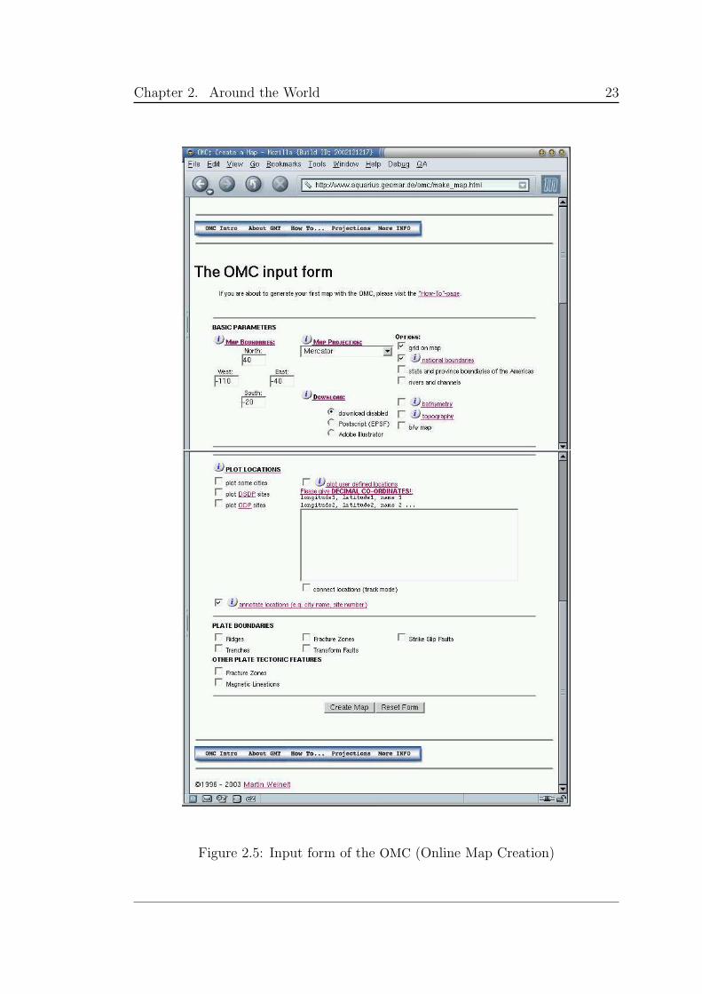
• Online Map Creation, or OMC, by Martin Weinelt is an efficient interac-
tive mapper powered by GMT. Its features include the capability of plotting
bathymetry, topography, city names in English, and other databases and to
map plate boundaries and other tectonic features. It also allows the user to
plot a manually entered path or series of locations with associated names.
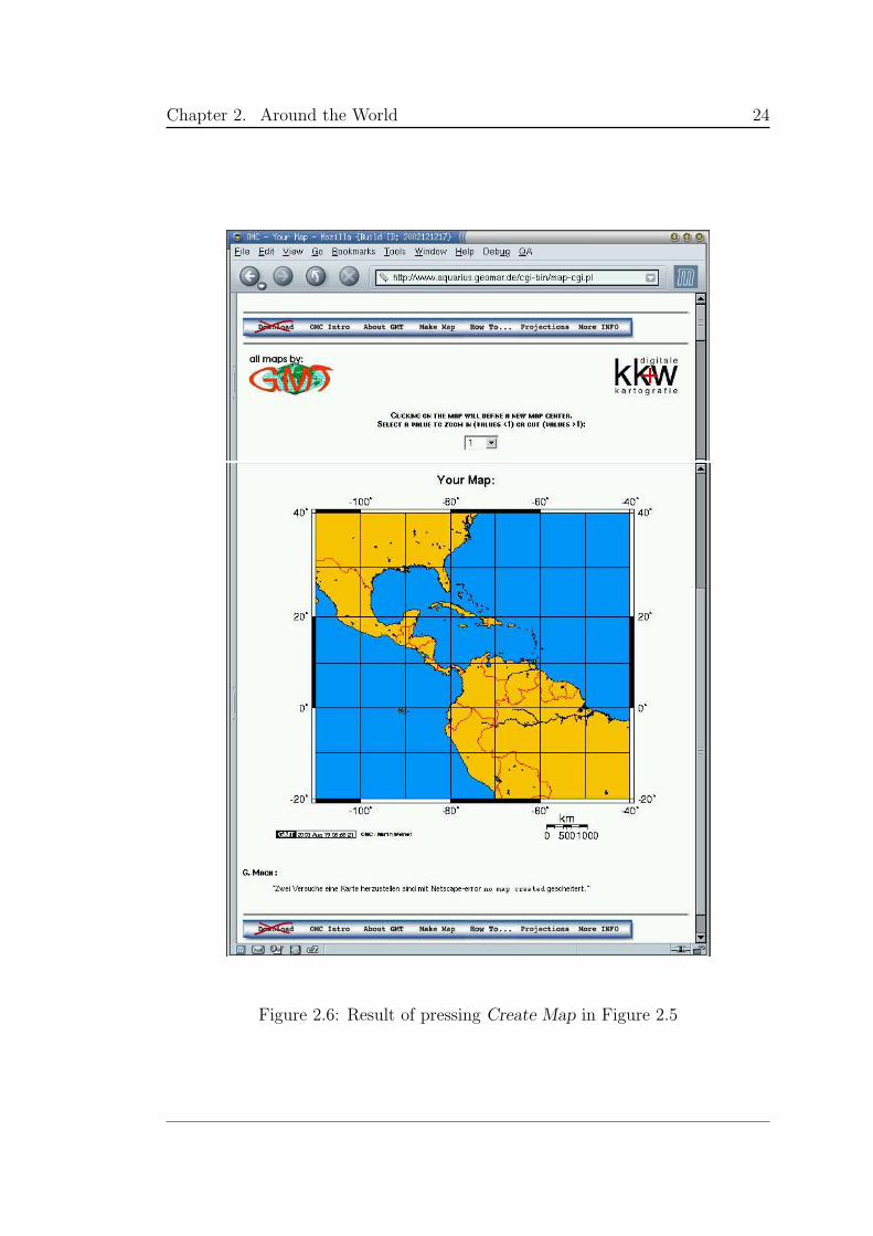
To create a map, the user is presented with a form to fill (Figure 2.5). The
request is sent to the server by clicking on the “Create Map” button, which
creates the map (Figure 2.6). With the result, the user can zoom and pan,
but to change any other parameter a new form must be used, resetting
all the parameters to default. Having only an initial entry form presents
an important limitation. If a change is required, the creative process is
interrupted and all parameters must be re-entered. Other problems include
no scale checking when plotting cities and limited initial map choices.
From all the servers visited, it has the best and cleanest user interface, with
supporting help pages. In other words, it does what it says it does.
http://www.aquarius.geomar.de/omc/2
Chapter 2. Around the World 23
Figure 2.5: Input form of the OMC (Online Map Creation)
Chapter 2. Around the World 24
Figure 2.6: Result of pressing Create Map in Figure 2.5
Chapter 2. Around the World 25
• The Interactive mapping and data analysis tool was developed at the
Institute for the Study of the Continents (INSTOC) and the Department of
Geological Sciences at Cornell University. The initiative was put in place
to provide direct access to their digital datasets through a Web-based tool.
For users looking for a specific dataset, the tool is well suited. However,
because no labels are provided, the ordinary user can easily get lost. This
tool is implemented using Java as an interface to ArcInfo.
Some disadvantages include limited map choices: only one map projection
is available, Equirectangular centered at 30 of latitude, and no zoom or
pan can be undertaken.
http://atlas.geo.cornell.edu/ima.html4
• The Harvard geospatial library map tool has a better set of map choices
than the tool from Cornell University, but there are fewer data sources
available to map. It starts with a nice topographic map of the world but
zooming in just a few levels inevitably yields a flat map with only a few
place names. The server is more an online retrieval system with metadata
search facilities, although it does offer mapping capabilities (using ArcInfo).
http://geodesy.harvard.edu/servlet/MainGeodesyMap5
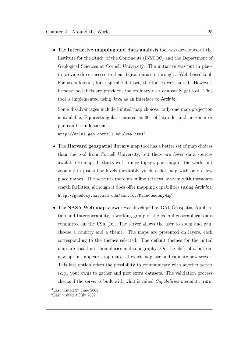
• The NASA Web map viewer was developed by GAI, Geospatial Applica-
tion and Interoperability, a working group of the federal geographical data
committee, in the USA [16]. The server allows the user to zoom and pan,
choose a country and a theme. The maps are presented on layers, each
corresponding to the themes selected. The default themes for the initial
map are coastlines, boundaries and topography. On the click of a button,
new options appear: crop map, set exact map size and validate new server.
This last option offers the possibility to communicate with another server
(e.g., your own) to gather and plot extra datasets. The validation process
checks if the server is built with what is called Capabilities metadata XML,
4Last visited 27 June 20025Last visited 3 July 2002.
Chapter 2. Around the World 26
Figure 2.7: NASA Web map viewer
Chapter 2. Around the World 27
an OpenGIS consortium specification for compatibility (explained below).
The server allows the user to join layers built by different servers, provided
they are compatible, to create a map.
When zooming into a region, the server does not convert into a flat map
(which is what the Harvard geospatial library does), but produces a picture
with larger pixels. This means that both servers lack the ability to look for
a more detailed database to plot when the map scale changes. The maps are
produced using ArcInfo. Figure 2.7 contains a snapshot of the Web page.
http://viewer.digitalearth.gov/2
The last two servers presented have Capabilities metadata XML, which, accord-
ing to specifications set out by the OpenGIS Consortium for Web map services [17],
is “metadata about a map server indicating its data holdings and abilities”. Using
XML, servers can communicate and exchange data.
Although XML is designed to store metadata, it does so in a rigid manner. At
the end of this chapter and throughout Chapters 5 and 6, we describe a changing
structure that represents among other things, the data. This structure can be
seen as a type of metadata that is adjusting to the changes in the data. And, as
we also see, data structures and “holdings” need to change because they are part
of a dynamic, evolving system. This structure-metadata look alike is the context.
Specialized mappers. The servers described below provide mapping services
for specific applications. They are mentioned because they offer interesting user
interfaces and good mapping results as well as access to different databases. All
maps are produced using GMT, the mapping tool of the Anita Conti Mapping
Server.
• The Ohio River Forecast Center is a Web site presenting maps of ob-
served and forecast water levels of the Ohio River. It behaves like an atlas
(precalculated maps), but the maps are regularly rebuilt with data no older
than 12 hours from the date stamp in the graphic.
http://www.erh.noaa.gov/er/ohrfc/4
Chapter 2. Around the World 28
• The Interactive Global Map of sea floor topography is based on satellite
altimetry and ship depth soundings developed by the NOAA Laboratory for
Satellite Altimetry. It maps and superposes these two datasets (i.e., satellite
altimetry and ship depth soundings) at different scales. This combination
is ideal for displaying major tectonic features, such as mid-ocean spreading
ridges or fracture zones.
http://ibis.grdl.noaa.gov/cgi-bin/bathy/bathD.pl5
• The SOPAC Map Browser allows users to map GPS arrays and networks.
Metadata about the GPS sites is available by clicking on mapped sites with
zoom and pan functions included.
http://sopac.ucsd.edu/maps/7
ODSN [18], the Ocean Drilling Stratigraphic Network in Germany established
by GEOMAR (Research Center for Marine Geosciences, Kiel) and the Geologi-
cal Institute of the University Bremen, has developed two mapping servers for
searching and plotting its own databases. Both servers use GMT as the mapping
engine and their Web interface is well designed, providing help pages and usage
manuals.
• ODNS Plate Tectonic Reconstruction Service lets the user interac-
tively create plate tectonic maps of any area in the world of a specified age.
The data from 197 plate fragments and terranes6 and their movement pa-
rameters is used to calculate the maps. The server also offers the possibility
of plotting user’s data and creating animated maps.
http://zeus.palaeoz.geomar.de/odsn/services/paleomap/paleomap.html7
• ODNS Fossil Distribution Plotting Service allows the user to plot the
distribution of fossils using the available datasets, which can be searched
for the occurrence of more than 5000 different fossils.
http://zeus.palaeoz.geomar.de/odsn/services/plot dist.html7
6A terrane is a crustal block or fragment that preserves a distinctive geological history thatis different from the surrounding areas and that is usually bounded by faults.
7Last visited 28 June 2002.
Chapter 2. Around the World 29
Summary
From the servers presented a few observations can be made:
1. The use of a specific server imposes on the end-user a number of require-
ments, ranging from browser version and type and languages to plug-ins
and cookies. Some of the requirements are ad hoc workarounds to the lim-
itations of both HTTP and HTML for developing complex interfaces, while
others correspond to a Web page designer’s personal choice of tools.
This situation makes it difficult for the user, who has his own computing
infrastructure, with its own limitations, by choice or by need. Users feel
bombarded by the different “extra” tools to run Web pages, when before
all that was needed was a plain browser (interpreting basic HTML). Some
users prefer not to allow cookies because of the potential loss of privacy
or security. But some sites simply cannot function without them. Other
users do not have the time or expertise to install plug-ins, or have hardware
limitations.
2. Some of the sites visited were difficult to understand, with awkward in-
put methods. Communicating map choices was difficult, to the point of
completely losing control of the interface and the map.
3. When a server fails to offer what the user requested, it should give the
closest result or inform the user of the problem, offering to restart. This
was missing from some of the visited servers and in some cases, a completely
different map was displayed. In extreme cases there was not even an error
message, just a blank page.
4. The best mapping servers have GMT as their mapping tool. These interfaces
systematically created better quality maps that corresponded more closely
to user requests.
Different interfaces showed different capabilities and analysis of data. Usually,
any feature provided by one mapper is lacking in the next. Current set ups do
Chapter 2. Around the World 30
not allow one to use the best parts of each. The same is true for database
availability, the key to interesting mapping. There is a large array of interesting
and diverse datasets in all the sites presented. Unfortunately, users cannot mix
datasets from different sites into the same map. The main problem is that they are
programmed in such a way that all the decisions are made explicit and adding
features is like developing a whole new system. For database processing, the
backends of the servers are rigidly built to understand only a fixed set of schemas,
with no flexibility to the changing nature of data for different purposes, scales or
applications. (Chapter 6 presents a new approach for storing many different data
schemas, of adding new ones without redesigning the system, and of querying
data of such heterogeneity.)
Other interface features, like collective browsing, user profiling or multilin-
gualism, were not present at all.
2.4 The Anita Conti Mapping Server
This section introduces the interface to the Anita Conti Mapping Server (details
are given in Chapter 7). At all times there is a map being shown, and the user
can change all the parameters pertaining to map creation. The same Web page
is used to control the look and feel of the page itself, to view a map, as well
as to control the creation of new maps. None of the previously mentioned Web
mappers provide this possibility.
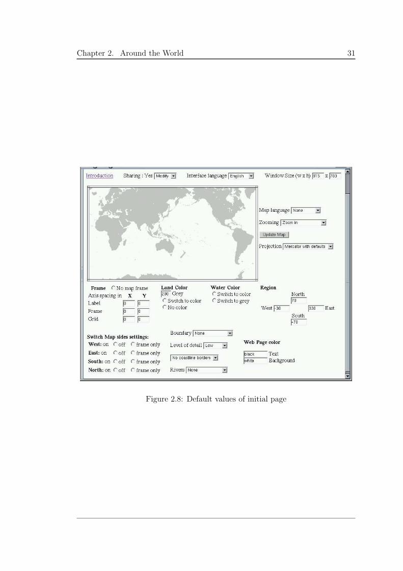
Figure 2.8 shows a snapshot of the Web page displaying default initial values
for a given user. The user can at any time change any settings, while keeping
the rest unchanged, hence the page changes only around the aspect just modified
by the user. The mapper offers more choices for controlling the map look and
content than any of the previously presented interfaces. In addition, users can
“collaborate” to make a map (see Chapter 4).
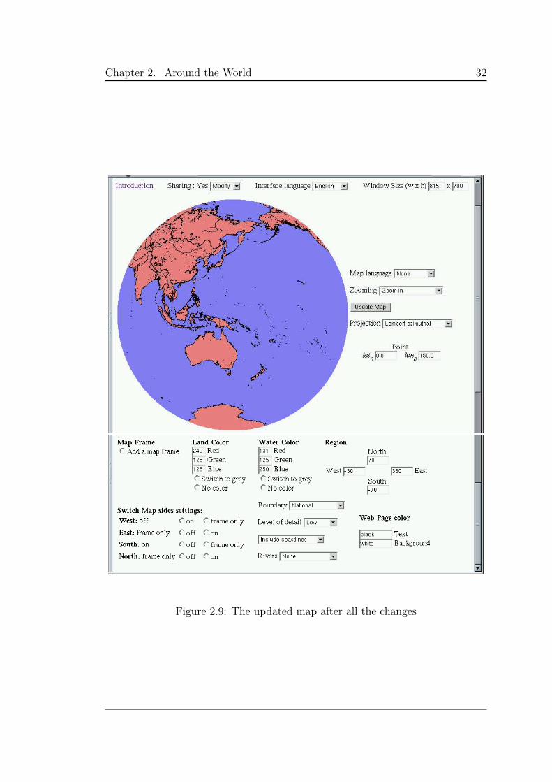
Figure 2.9 shows the Web page created after choosing a number of options
and the Update Map button being clicked on. Chapter 7 contains a detailed
presentation of the work undertaken to get from the default page to this one.
Chapter 2. Around the World 31
Figure 2.8: Default values of initial page
Chapter 2. Around the World 32
Figure 2.9: The updated map after all the changes
Chapter 3
The Essence
The Context: bringing the [common] ground to the fore
This chapter gives a historical overview of the development of intensional pro-
gramming and of the successive improvements in understanding how the context
interacts with context-dependent software and documents, and other permeated
entities. If structured programming requires detailed analysis of data structures
and algorithms, and OO programming requires correct OO design of class hi-
erarchies, successful intensional programming requires full understanding of the
context. What is invisible, namely the context — or the ground, in Marshall
McLuhan’s words — must be made visible and studied and analyzed explicitly.
The background becomes the foreground.
The term intensional programming is derived from Richard Montague’s in-
tensional logic [19], and Rudolf Carnap’s distinction between intension and ex-
tension [20]. This chapter begins with key results from formal logic, working
from Aristotle’s syllogisms to Scott’s indexed possible worlds [21]. For millennia,
the variants of modal logic, including intensional logic, were considered to be an
important part of formal logic; only during a brief period (late 19th to mid-20th
centuries) were these officially excluded from Logic.
After this brief incursion into logic, we move on to the discovery of intension-
ality as it pertains to computing, with the successive developments of the Lucid
multidimensional programming language [22], whose variables are intensions.
33

Chapter 3. The Essence 34
Intensional versioning arises from Plaice and Wadge’s insight that possible-
worlds semantics is applicable not simply to the behavior of software but also
to its structure [23]. Using this idea, systems have been created to build soft-
ware variants and adaptable Web pages on demand. Hence, both software and
documents can be understood as intensions.
Combining both intensional programming and intensional versioning, Swo-
boda’s ISE [24] is the first intensional imperative language. For the first time,
one can write programs that explicitly manipulate a multidimensional context,
each dimension corresponding to a specific parameter, and have that context
implicitly modify the semantics of every entity in the program.
With the context becoming a first-class value that can be manipulated ex-
plicitly, new questions arise: What happens if different entities are put in the
same context? What about entities of a different nature? Can an entity be in
several contexts simultaneously? Attempts to answer these questions have led
to the development of the intensional community and of distributed intensional
programming.
The context, however, must become active for communities to become alive.
With the development of Swoboda’s libintense intensional context software [1],
the context becomes a reactive machine: it can actively perform tasks. This new
context is called an æther, and the main difference is that it has participants
that are notified of changes. The æther reacts to a change of context by itself
transmitting changes of context to its participants.
To implement an intensional mapping server requires further developments
in intensional programming and the map itself must be viewed through an in-
tensional lens. All of the variance of textual documents still applies to maps,
but there is more: maps simultaneouly present context and content. The map,
quite literally, makes the ground visible. And to create versioned maps, a full
intensional infrastructure is needed to support the myriads of parameters (repre-
senting context and content) and to process them to create the current version
of the map. The change of just a single parameter might trigger a whole series of
processes to fulfill the new map requirement.
Chapter 3. The Essence 35
3.1 Intensional logic
Ever since the beginnings of logic, it has been understood that there is a difference
between sentences that are necessarily true because of the nature of logic and
sentences that just happen to be true because of contigent factors. For example,
the sentence:
Nine is a perfect square. (3.1)
and the sentence:
The number of planets is nine. (3.2)
are both true, but the nature of the truth in the two sentences is different, and
they cannot be substituted equivalently into other sentences, as in:
Kepler believed that nine is a perfect square. (3.3)
and:
Kepler believed that the number of planets is nine. (3.4)
Given that Johannes Kepler (1571–1630) was a gifted mathematician and remark-
able astronomer, and that only six planets were known during his lifetime, it is
likely that Equation 3.3 is true and that Equation 3.4 is false.
The existence of this general problem was recognized by Aristotle (384–322
B.C.E.), The Logician, “the first to state formal laws and rules” for logic [25, p.19].
In his writings on formal logic, collectively known as the Organon, Aristotle
introduced modal logic and distinguished between two modes of truth: necessity
and contigency [25, pp.55-6].
Because of the comprehensive nature of Aristotle’s work, his writings domi-
nated all study of logic in the Western world until the development of mathemat-
ical logic, beginning in the late seventeenth century. Nevertheless, developments
did take place in the understanding of modalities, often with respect to theological
arguments as to the nature or existence of God and the world.
In particular, John Duns Scotus (1265/6–1308), a Franciscan scholar, intro-
duced the concept of possible worlds. In opposition to Thomas Aquinas, Scotus
Chapter 3. The Essence 36
asserted the primacy of Divine Will over Divine Intellect : the existing world does
not exist because of some moral necessity, but, rather, because of a divine choice.
The world we live in could be different and it is just one of numerous logically
consistent possible worlds.
Gottfried Wilhelm von Leibniz (1646–1716), the founder of mathematical
logic [26, p.258], put forward that “a necessary truth must hold in all possi-
ble worlds.” [20, p.10] Nevertheless, he too used logic to participate in theological
arguments. In his Essais de Theodicee sur la bonte de Dieu, la liberte de l’homme
et l’origine du mal (1710) he stated that notwithstanding the many evils of this
world, “We live in the best of all possible worlds.” Francois Marie Arouet de
Voltaire (1694–1778) replied in his Candide ou l’optimisme that “If this is the
best of all possible worlds, what then are the others?”
As mathematical logic post-Leibniz developed, with a strong anti-Aristotelian
bias, the modalities were pushed aside, at least temporarily, and sentences were
designated as being either true or false. The focus of attention was placed en-
tirely on mathematical rigor. In so doing, the distinction between intension and
extension surfaced.
Bertrand Russell wrote (1903) [26, p.361]: “Class may be defined either ex-
tensionally or intensionally. That is to say, we may define the kind of object
which is a class, or the kind of concept which denotes a class: this is the precise
meaning of the opposition of extension and intension in this connection.” But, he
believed “this distinction to be purely psychological”. For Russell, the difference
between extension and intension is quantitative, not qualitative: the intension is
only needed because one cannot write down infinite classes.
However, the distinction between the two is qualitative as well. Already in the
3rd century, Porphyry of Tyre noted the difference between genus and species in
his Isagoge [26, pp.135,258]. (These terms are kept in today’s classification of life:
genus being a taxonomic grouping of organisms and containing several species ;
species designating a group of organisms capable of interbreeding.) More recently,
the Logique de Port-Royal (Antoine Arnault et Pierre Nicole, 1662), distinguished
comprehension and etendue, and Leibniz retained these terms. Leibniz called the
Chapter 3. The Essence 37
“comprehension of an idea the attributes which it contains and which cannot be
taken from it without destroying it”. He called “the extension of an idea the
subjects to which it applies”. [26, p.259]
Rudolf Carnap (1891–1970), in Meaning and Necessity, made explicit the con-
nection between Leibniz’s possible worlds and the intension-extension duality.
He began with a first-order system SI with standard connectives and quantifiers.
A state description is a class of sentences in SI “which contains for every atomic
sentence either this sentence or its negation, but not both, and no other sen-
tences”. The description “obviously gives a complete description of a possible
state of the universe of individuals with respect to all properties and relations
expressed by predicates of the system. Thus the state-descriptions represent
Leibniz’ possible worlds”. [20, p.9]
Carnap then distinguished between truth and L-truth. Truth simply means
truth with respect to a specific state description. L-truth means truth in all state
descriptions. Using the conventions that two predicators (predicte symbols) have
the same extension if, and only if, they are equivalent and the same intension if,
and only if, they are L-equivalent, Carnap came up with the following concepts:
extension intension
predicator (degree one) corresponding class corresponding concept
sentence truth-value proposition expressed by it
individual expression to which it refers concept expressed by it
To give an overall semantics to this process, Carnap stated that “an assign-
ment is a function which assigns to a variable and a state-description as arguments
an individual constant as value” [20, p.170]. As a result, an intension becomes
a mapping from the state-descriptions to its extensions. According to Dowty
et al. [27, p.145], Carnap’s “intension is nothing more than all the varying ex-
tensions (denotations) the expression can have, put together and ‘organized’, as
it were, as a function with all possible states of affairs as arguments and the
appropriate extensions arranged as values.”
Chapter 3. The Essence 38
Saul Kripke (1940–) went further and developed possible world semantics for
modal logic, in which the possible worlds are indices. “The main and the original
motivation for the ‘possible world analysis’ — and the way it clarified modal
logic — was that it enabled modal logic to be treated by the same set theoretic
techniques of modal theory that proved so successful when applied to extensional
logic. It is also useful in making certain concepts clear.” [28, p.19]
For Kripke, a possible world is “a little more than the miniworld of school
probability blown large.” [28, p.18] Kripke does not attempt to define a ‘complete
counterfactual course of events’ arguing further that there is no need to do so.
“A practical description of the extent to which the ‘counterfactual situation’
differs in the relevant way from the actual facts is sufficient.”
This will prove particularly useful later on when describing and formalizing
only the changes to the context (and not the entire context) in a running system,
changes that need “broadcasting”. These changes are called Context Operations.
According to Dowty et al. [27, p.145] “with the advent of Kripke’s semantics
for modal logic (taking possible worlds as indices), it became possible for the first
time to give an unproblematic formal definition of intension for formalized lan-
guages.” Soon after, Richard Montague (1930–1971) created his intensional logic,
culminating in his paper “The Proper Treatment of Quantification in Ordinary
English” [19].
All this was generalized by Dana Scott in his 1969 paper “Advice on Modal
Logic” [21]. He assumes a nonempty set I of reference points that do not require
any accessibility relation, just like in possible worlds semantics. The truth value of
a sentence φ at a particular point is the extension of φ at that point. The intension
of φ is an element of 2I , a function that maps each point i to the extension
of φ at i. A (unary) intensional operator is a function mapping intensions to
intensions, i.e., an element of 2I → 2I .
Bill Wadge, in his “Intensional Logic in Context” [29] explained the formal
origins of intensional programming and offers fascinating insights into the social
origins of modal and intensional logic. In this article, he quotes the following
prescient passage from Scott:
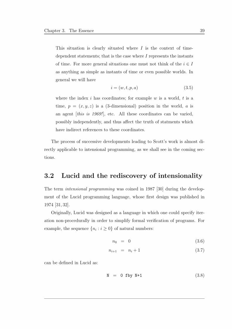
Chapter 3. The Essence 39
This situation is clearly situated where I is the context of time-
dependent statements; that is the case where I represents the instants
of time. For more general situations one must not think of the i ∈ I
as anything as simple as instants of time or even possible worlds. In
general we will have
i = (w, t, p, a) (3.5)
where the index i has coordinates; for example w is a world, t is a
time, p = (x, y, z) is a (3-dimensional) position in the world, a is
an agent [this is 1969! ], etc. All these coordinates can be varied,
possibly independently, and thus affect the truth of statments which
have indirect references to these coordinates.
The process of successive developments leading to Scott’s work is almost di-
rectly applicable to intensional programming, as we shall see in the coming sec-
tions.
3.2 Lucid and the rediscovery of intensionality
The term intensional programming was coined in 1987 [30] during the develop-
ment of the Lucid programming language, whose first design was published in
1974 [31, 32].
Originally, Lucid was designed as a language in which one could specify iter-
ation non-procedurally in order to simplify formal verification of programs. For
example, the sequence ni : i ≥ 0 of natural numbers:
n0 = 0 (3.6)
ni+1 = ni + 1 (3.7)
can be defined in Lucid as:
N = 0 fby N+1 (3.8)
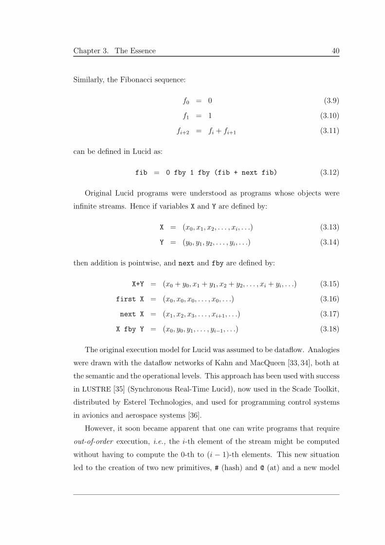
Chapter 3. The Essence 40
Similarly, the Fibonacci sequence:
f0 = 0 (3.9)
f1 = 1 (3.10)
fi+2 = fi + fi+1 (3.11)
can be defined in Lucid as:
fib = 0 fby 1 fby (fib + next fib) (3.12)
Original Lucid programs were understood as programs whose objects were
infinite streams. Hence if variables X and Y are defined by:
X = (x0, x1, x2, . . . , xi, . . .) (3.13)
Y = (y0, y1, y2, . . . , yi, . . .) (3.14)
then addition is pointwise, and next and fby are defined by:
X+Y = (x0 + y0, x1 + y1, x2 + y2, . . . , xi + yi, . . .) (3.15)
first X = (x0, x0, x0, . . . , x0, . . .) (3.16)
next X = (x1, x2, x3, . . . , xi+1, . . .) (3.17)
X fby Y = (x0, y0, y1, . . . , yi−1, . . .) (3.18)
The original execution model for Lucid was assumed to be dataflow. Analogies
were drawn with the dataflow networks of Kahn and MacQueen [33, 34], both at
the semantic and the operational levels. This approach has been used with success
in LUSTRE [35] (Synchronous Real-Time Lucid), now used in the Scade Toolkit,
distributed by Esterel Technologies, and used for programming control systems
in avionics and aerospace systems [36].
However, it soon became apparent that one can write programs that require
out-of-order execution, i.e., the i-th element of the stream might be computed
without having to compute the 0-th to (i − 1)-th elements. This new situation
led to the creation of two new primitives, # (hash) and @ (at) and a new model
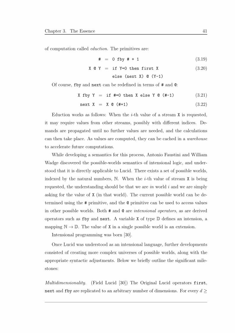
Chapter 3. The Essence 41
of computation called eduction. The primitives are:
# = 0 fby # + 1 (3.19)
X @ Y = if Y=0 then first X
else (next X) @ (Y-1)
(3.20)
Of course, fby and next can be redefined in terms of # and @:
X fby Y = if #=0 then X else Y @ (#-1) (3.21)
next X = X @ (#+1) (3.22)
Eduction works as follows: When the i-th value of a stream X is requested,
it may require values from other streams, possibly with different indices. De-
mands are propagated until no further values are needed, and the calculations
can then take place. As values are computed, they can be cached in a warehouse
to accelerate future computations.
While developing a semantics for this process, Antonio Faustini and William
Wadge discovered the possible-worlds semantics of intensional logic, and under-
stood that it is directly applicable to Lucid. There exists a set of possible worlds,
indexed by the natural numbers, N. When the i-th value of stream X is being
requested, the understanding should be that we are in world i and we are simply
asking for the value of X (in that world). The current possible world can be de-
termined using the # primitive, and the @ primitive can be used to access values
in other possible worlds. Both # and @ are intensional operators, as are derived
operators such as fby and next. A variable X of type D defines an intension, a
mapping N → D. The value of X in a single possible world is an extension.
Intensional programming was born [30].
Once Lucid was understood as an intensional language, further developments
consisted of creating more complex universes of possible worlds, along with the
appropriate syntactic adjustments. Below we briefly outline the significant mile-
stones:
Multidimensionality. (Field Lucid [30]) The Original Lucid operators first,
next and fby are replicated to an arbitrary number of dimensions. For every d ≥
Chapter 3. The Essence 42
0, there are operators initiald, succd, sbyd, where first = initial0, next =
succ0, and fby = sby0. Multidimensional objects can be manipulated, but the
dimensions cannot be manipulated, exchanged, or transposed.
Dimensional abstraction. (Indexical Lucid [37]) The Original Lucid operators #
and @ are generalized to #.d and @.d. Dimensions can be declared as identifiers
and as formal parameters to functions, and can be passed as actual parameters
to functions during execution. Dimensions can now be manipulated, exchanged,
transposed, etc., but the rank of an object — the set of dimensions in which it
varies — cannot be accessed.
Functions as multidimensional variables [38, 39]. Functions can be replaced by
variables varying in a multidimensional space, where the dimensions do not take
integers as values, but, rather, lists of integers. Using this technique, higher-
order functions can be evaluated on demand without needing complicated closure
operations. The possible worlds here correspond to snapshots of the traditional
calling stack used in ordinary programming languages.
Dimensions as values [40, 41]. By allowing declared dimensions to be used as
ordinary values, the total dimensionality of an object becomes directly accessible.
However, all dimensions must still be created lexically, and cannot be created on
demand, during execution.
Values as dimensions [22]. Any ground (scalar) value for which equality testing
makes sense can be used as a dimension. Dimensions can therefore be created on
the fly, opening up many new possibilities.
Dimensions for logic programming [42, 43]. The eductive process is applied not
to a base functional programming language, but, rather, to a logic programming
language. Generalizations lead to multidimensional logic programming [44].
Further generalizations still need to be undertaken. The work with functions
Chapter 3. The Essence 43
is still not complete, since arbitrary recursion is still not fully understood. In ad-
dition, data types themselves need to be studied as intensions. No interpreters for
Lucid have been developed since Indexical Lucid, because of the above unsolved
generalizations. In studying the data types, a new problem arose: the structure
itself of software can be understood using possible world semantics.
3.3 Two-stage eduction
The first work in this direction was undertaken by Weichang Du, who developed
a 3D-spreadsheet based on intensional logic [45–47]. In his model, a spreadsheet
is an intension, where the extensions are the values in the individual cells. Unlike
in Lucid, where variables have a single definition, the spreadsheet can be created
with several definitions, relevant to the whole spreadsheet, just a plane, just a
row, just a column or just a cell. The eductive process is two-stage: for any cell,
first the most relevant — the most specific — definition must be found; second,
that definition is evaluated, possibly using intensional operators to refer to the
values of other cells.
Similar work was undertaken by Senhua Tao, who created the intensional
attribute grammar [48]. Each attribute is an intension, and, as with the spread-
sheets, multiple definitions can be given for each attribute, relevant to the node
type within the parse tree of a sentence. Using this framework, attributes can be
defined according to a time dimension, thereby avoiding the need for self-recursive
attribute definitions.
3.4 Intensional versioning
In his 1974 seminal paper on software configuration [49], David Parnas described
a need for software families. In his vision, a family should contain many different
pieces of software, all slightly different; these are now called variants.
Possible world semantics is ideally suited for expressing this variance. The
Chapter 3. The Essence 44
software family is an intension and the individual variants are extensions. How-
ever, a basic software engineering principle is to have a single canonical copy
of every entity and to avoid duplicate entities (i.e., their variants) in order to
prevent unnecessary branching, a very error-prone proccess. The question that
arises is: How can possible world semantics be used to provide maximum sharing
of code across the variants?
The answer was provided in a paper by Plaice and Wadge [23]. They defined
a version space V (∋ V ), defining a universe of possible worlds, along with a
partial refinement order ⊑. (The version space is now known as context space
and subsequent syntax has been adjusted for this text to be compatible with later
discussions.)
The syntax for versions allows for subversioning and merging:
V ::= ǫ | v | V :V | V + V (3.23)
where ǫ is the empty version, v is a scalar value, : is used to denote subversioning
and + is used to merge versions. There is a refinement order ⊑, defined syntac-
tically, naturally from the structure of the versions, that ensures that V + V ′ is
the least upper bound, with respect to ⊑, of V and V ′.
For a given software family, the version space is assumed to be uniform, and
all components are understood to vary conceptually across the entire version
space. Physically, on the other hand, any given component may only come in a
very limited number of versions. When a specific version of the system is to be
built, then the most relevant version of each component is selected for the build
process. Components here mean not only pieces of codes, but also splash screens,
drop-down menus, build files, configuration files, documentation, whatever might
constitute part of the final deliverable.
This means that for each component C, if VC is the set of versions of C and
version Vreq is requested, then VC , the selected version of C, is:
VC = best(Vreq,VC) = maxV ∈ VC : V ⊑ Vreq (3.24)
This approach is called the variant substructure principle.
Chapter 3. The Essence 45
Plaice and Wadge validated this approach by taking a C programming envi-
ronment, called Sloth [50], and adding versions transparently. The derived system
is called Lemur. With Lemur, creating new variants of a piece of software was rad-
ically simplified in comparison to the standard methology.
The Sloth system is used to build C modules. Each module is held in a
directory, and a number of component files within the directory are used to auto-
matically generate a C file named prog.c for that module. Any component file
can come in several versions, each encoded as a tag at the filename level. When a
version of the module is requested, the most relevant version of each component
file is chosen. In the end, the actual built version of prog.c is the least upper
bound of the chosen versions of the component files.
Formally, if system S consists of components C1, . . . , Cn, and version Vreq of S
is requested, then VS, the version of S that will actually be built, will be:
VS = VC1+ · · ·+ VCn
, VCi= best(Vreq,VCi
) (3.25)
This process is called version inheritance: the refined versions inherit from coarser
versions by default.
A Sloth C module can import other modules using an import list. This import
list can itself be versioned, using the mechanisms described above. But it is
possible to go further: for each named component in the import list, a new
requested version may be attached. For each of these components, Sloth proceeds
with the new requested version, and returns the best possible version of the built
subsystem. The versions of these subsystems then contribute to the version tag
of the whole system.
The intensional versioning approach is based on a uniform version space and
avoids the unrealistic supposition that the latest version has been developed for
each and every component. Each component, in turn, has its own version space, a
subset of the system’s version space. Nevertheless, as in philosophy, each version
can be considered to be a possible world, a complete state of affairs.
To illustrate with an example, to assemble version 6.2 of a word processor,
all the version 6.2 components are needed: makefile, spell checkers, line-breaking
Chapter 3. The Essence 46
functions, etc. But each component of the word processor has its own set of
components (error messages, menus), each with its own version space. Since not
all the components have the latest version (i.e., 6.2), version inheritance through
best-fit refinement is needed to resolve the issue. If version 6.2 refines version 6.1,
then version 6.2 of the line-breaking algorithm is the same as version 6.1 unless
a separate 6.2 version has been developed. So, say the release of version 6.1 of
the line breaking module includes line breaking for English (version 6.0), French
(version 6.1) and Malayalam (version 6.1). A new and improved version of
the Malayalam algorithm is developed and implemented to produce version 6.2.
When version 6.2 of the line-breaking module is requested, the assembled version
includes line breaking for English (version 6.0), French (version 6.1) and the new
Malayalam (version 6.2). Version inheritance makes the uniform version space
practical, since it allows different versions of the system components to share code
and data.
Intensional versioning tremendously simplifies configuration of any system,
or of parts of it. Configuration is automatic, since version V of a compound
entity is the result of combining version V of each of its parts. Applications with
many components can be assembled without human interaction. And since the
configuration is demand-driven, along with version inheritance, it is possible to
have very large version spaces without tying up resources by creating and storing
unwanted versions.
The mechanism proposed here in no way makes any supposition that the
entities to be versioned are files. Assuming appropriate syntax and supporting
run-time systems, any entity can be versioned and adapt itself to any context.
3.5 Intensional documents and markup
The original article in intensional versioning was published in March 1993, around
the time that the World Wide Web was becoming widely known. At that time,
most Web sites consisted of purely static Web pages, all produced manually.
However, there were a few interesting sites that did things differently: By using
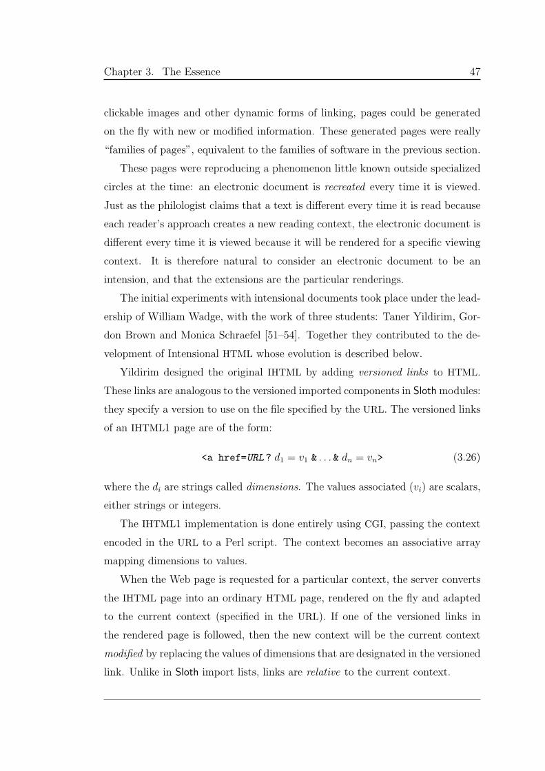
Chapter 3. The Essence 47
clickable images and other dynamic forms of linking, pages could be generated
on the fly with new or modified information. These generated pages were really
“families of pages”, equivalent to the families of software in the previous section.
These pages were reproducing a phenomenon little known outside specialized
circles at the time: an electronic document is recreated every time it is viewed.
Just as the philologist claims that a text is different every time it is read because
each reader’s approach creates a new reading context, the electronic document is
different every time it is viewed because it will be rendered for a specific viewing
context. It is therefore natural to consider an electronic document to be an
intension, and that the extensions are the particular renderings.
The initial experiments with intensional documents took place under the lead-
ership of William Wadge, with the work of three students: Taner Yildirim, Gor-
don Brown and Monica Schraefel [51–54]. Together they contributed to the de-
velopment of Intensional HTML whose evolution is described below.
Yildirim designed the original IHTML by adding versioned links to HTML.
These links are analogous to the versioned imported components in Slothmodules:
they specify a version to use on the file specified by the URL. The versioned links
of an IHTML1 page are of the form:
<a href=URL ? d1 = v1 & . . . & dn = vn> (3.26)
where the di are strings called dimensions. The values associated (vi) are scalars,
either strings or integers.
The IHTML1 implementation is done entirely using CGI, passing the context
encoded in the URL to a Perl script. The context becomes an associative array
mapping dimensions to values.
When the Web page is requested for a particular context, the server converts
the IHTML page into an ordinary HTML page, rendered on the fly and adapted
to the current context (specified in the URL). If one of the versioned links in
the rendered page is followed, then the new context will be the current context
modified by replacing the values of dimensions that are designated in the versioned
link. Unlike in Sloth import lists, links are relative to the current context.
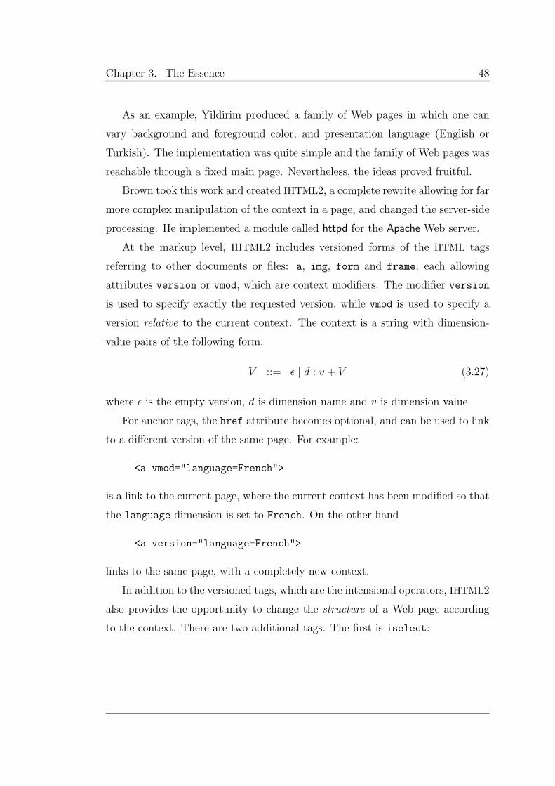
Chapter 3. The Essence 48
As an example, Yildirim produced a family of Web pages in which one can
vary background and foreground color, and presentation language (English or
Turkish). The implementation was quite simple and the family of Web pages was
reachable through a fixed main page. Nevertheless, the ideas proved fruitful.
Brown took this work and created IHTML2, a complete rewrite allowing for far
more complex manipulation of the context in a page, and changed the server-side
processing. He implemented a module called httpd for the Apache Web server.
At the markup level, IHTML2 includes versioned forms of the HTML tags
referring to other documents or files: a, img, form and frame, each allowing
attributes version or vmod, which are context modifiers. The modifier version
is used to specify exactly the requested version, while vmod is used to specify a
version relative to the current context. The context is a string with dimension-
value pairs of the following form:
V ::= ǫ | d : v + V (3.27)
where ǫ is the empty version, d is dimension name and v is dimension value.
For anchor tags, the href attribute becomes optional, and can be used to link
to a different version of the same page. For example:
<a vmod="language=French">
is a link to the current page, where the current context has been modified so that
the language dimension is set to French. On the other hand
<a version="language=French">
links to the same page, with a completely new context.
In addition to the versioned tags, which are the intensional operators, IHTML2
also provides the opportunity to change the structure of a Web page according
to the context. There are two additional tags. The first is iselect:
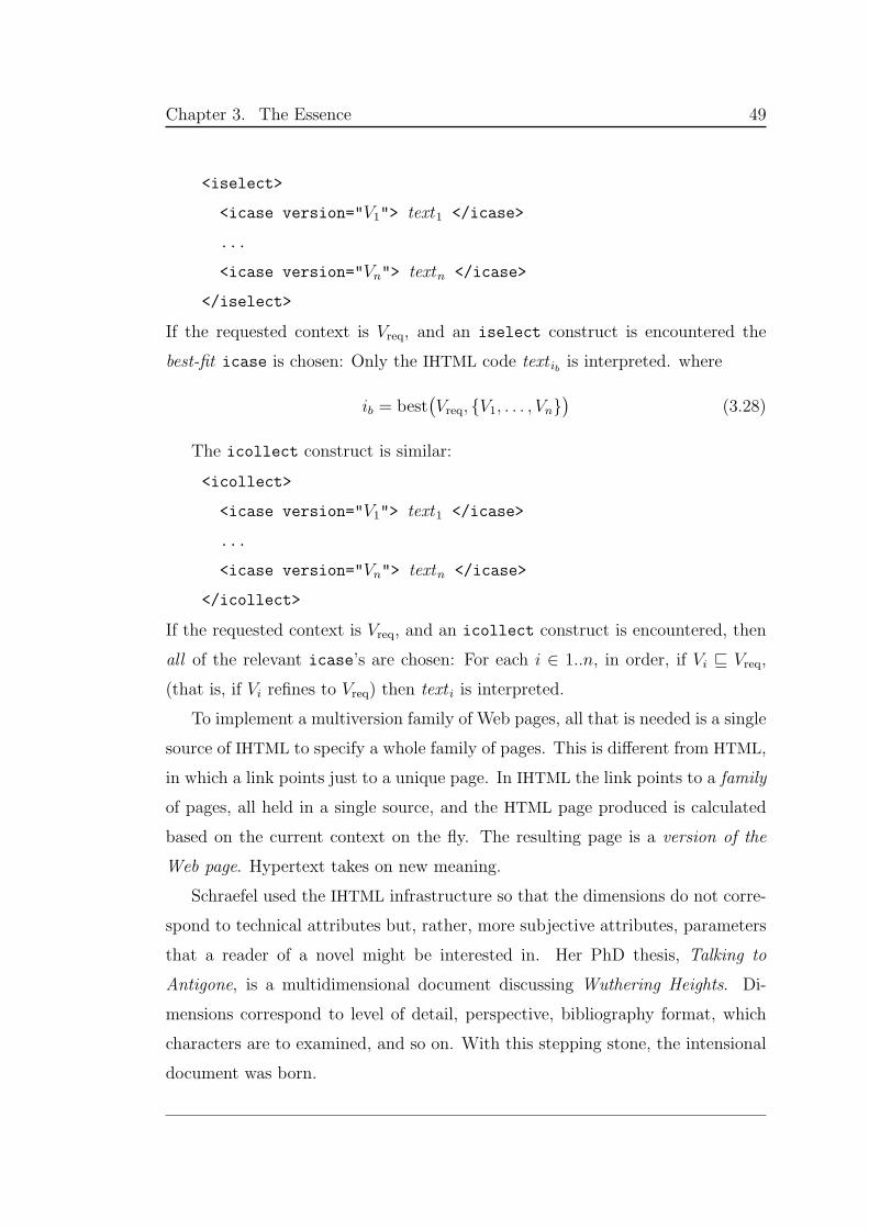
Chapter 3. The Essence 49
<iselect>
<icase version="V1"> text1 </icase>
...
<icase version="Vn"> textn </icase>
</iselect>
If the requested context is Vreq, and an iselect construct is encountered the
best-fit icase is chosen: Only the IHTML code text ib is interpreted. where
ib = best(Vreq, V1, . . . , Vn
)(3.28)
The icollect construct is similar:
<icollect>
<icase version="V1"> text1 </icase>
...
<icase version="Vn"> textn </icase>
</icollect>
If the requested context is Vreq, and an icollect construct is encountered, then
all of the relevant icase’s are chosen: For each i ∈ 1..n, in order, if Vi ⊑ Vreq,
(that is, if Vi refines to Vreq) then text i is interpreted.
To implement a multiversion family of Web pages, all that is needed is a single
source of IHTML to specify a whole family of pages. This is different from HTML,
in which a link points just to a unique page. In IHTML the link points to a family
of pages, all held in a single source, and the HTML page produced is calculated
based on the current context on the fly. The resulting page is a version of the
Web page. Hypertext takes on new meaning.
Schraefel used the IHTML infrastructure so that the dimensions do not corre-
spond to technical attributes but, rather, more subjective attributes, parameters
that a reader of a novel might be interested in. Her PhD thesis, Talking to
Antigone, is a multidimensional document discussing Wuthering Heights. Di-
mensions correspond to level of detail, perspective, bibliography format, which
characters are to examined, and so on. With this stepping stone, the intensional
document was born.
Chapter 3. The Essence 50
This development led to research into the origins of hypertext and to the
conclusion that much of this technical development was forecast — although not
necessarily implemented — long before. Vannevar Bush wrote in 1945 [55] about
the Memex, a machine in which one can read documents at different speed or
different levels of detail. Ted Nelson, who coined the term hypertext in 1965,
also invented the terms stretchtext, plytext and poptext, where, depending of the
actions of the user, text looks different. By using the standard intensional pro-
gramming technique that any problem can be solved by adding a new dimension,1
Nelson’s stretchtext, plytext and poptext are all easily implemented.
Nevertheless, further examination of Nelson’s writings [56] showed a signifi-
cant difference between his view of hypertext and the intensional view. Nelson
envisages that any reader can take bits and pieces of other documents to produce
a hypertext system with two-way links (to ensure strict copyright control). For
him, a hypertext family of documents consists solely of juxtaposing extensions (of
other people’s work). His family of documents is not an intension, but a collection
of extensions. But as concluded in [56], “Hypertext, if it is to be meaningful, can
only mean intensional hypertext.”
By the time IHTML was fully developed, manyWeb pages were being produced
dynamically using scripting languages such as Perl. It was time for a full fledged
intensional programming language (see next section).
At the same time, Yannis Stavrakas, Manolis Gergatsoulis and Panos Rondo-
giannis continued with the approach of intensionalizing markup languages. They
developed Multidimensional XML [57] along with an intensionalized version of
XSLT. In the long run, their work will be highly relevant, but currently there is
no distribution of any software based on their ideas.
1A variation on the well known dictum that any computer problem can be solved with anextra level of indirection.
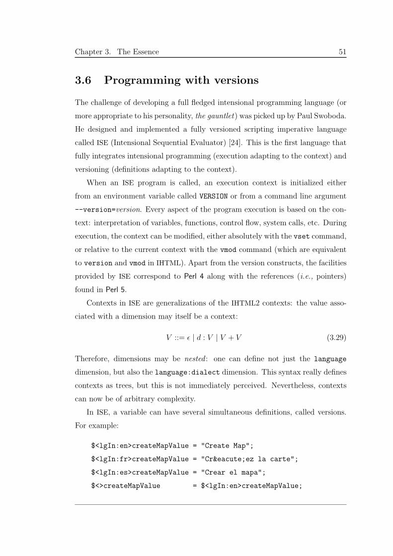
Chapter 3. The Essence 51
3.6 Programming with versions
The challenge of developing a full fledged intensional programming language (or
more appropriate to his personality, the gauntlet) was picked up by Paul Swoboda.
He designed and implemented a fully versioned scripting imperative language
called ISE (Intensional Sequential Evaluator) [24]. This is the first language that
fully integrates intensional programming (execution adapting to the context) and
versioning (definitions adapting to the context).
When an ISE program is called, an execution context is initialized either
from an environment variable called VERSION or from a command line argument
--version=version. Every aspect of the program execution is based on the con-
text: interpretation of variables, functions, control flow, system calls, etc. During
execution, the context can be modified, either absolutely with the vset command,
or relative to the current context with the vmod command (which are equivalent
to version and vmod in IHTML). Apart from the version constructs, the facilities
provided by ISE correspond to Perl 4 along with the references (i.e., pointers)
found in Perl 5.
Contexts in ISE are generalizations of the IHTML2 contexts: the value asso-
ciated with a dimension may itself be a context:
V ::= ǫ | d : V | V + V (3.29)
Therefore, dimensions may be nested : one can define not just the language
dimension, but also the language:dialect dimension. This syntax really defines
contexts as trees, but this is not immediately perceived. Nevertheless, contexts
can now be of arbitrary complexity.
In ISE, a variable can have several simultaneous definitions, called versions.
For example:
$<lgIn:en>createMapValue = "Create Map";
$<lgIn:fr>createMapValue = "Créez la carte";
$<lgIn:es>createMapValue = "Crear el mapa";
$<>createMapValue = $<lgIn:en>createMapValue;
Chapter 3. The Essence 52
the variable createMapValue is defined in four versions: the English, French and
Spanish of the language interface dimension, and the default version, defined to
be the same as the English version.
Most of the ISE constructs allow the insertion of version expressions V, which
are expressions to alter the context of evaluation in some way. The absolute
version expression is written <V >, and designates a completely new context. The
relative version expression is written [V ], and designates a modification of a
context. At all times, there is a running, current context. If the instruction
vset(V ) is executed, then this context is changed to <V >. If the instruction
vmod(V ) is executed, then the context is changed to [V ].
Context changes follow the scoping rules of the program structure, and can
be restricted to individual blocks. Hence, in:
do V B (3.30)
the context change defined by V is restricted to the block B. Similarly, in:
while (C) V B (3.31)
so long as the conditional expression C is true, block B is executed with the
context change defined by V. Slightly more complicated is:
if (C0) V0 B0
elif (C1) V1 B1
. . .
else Vn Bn
(3.32)
If Ci is the first true expression, block Bi is executed with the context change
defined by Vi.
The most complicated structure in ISE is the function call. Like variables,
functions — but not their types — can be defined in several versions. This
means that there are several function definitions, each tagged with a version.
And the function calls are themselves versioned! The three main syntactic forms
of a function call are:
Chapter 3. The Essence 53
fname Vreq Vexec (args) (3.33)
fname? Vreq Vexec (args) (3.34)
fname! Vreq Vexec (args) (3.35)
To evaluate which definition of fname to execute, the current context is modified
by Vreq to obtain Vreq. The definition to execute is that whose version (Vbest) best
fits Vreq. To obtain the context of execution, there are three choices corresponding
to the syntactic forms:
• fname : the context is the Vexec modification of the current context.
• fname? : the context is the Vexec modification of the requested context Vreq.
• fname! : the context is the Vexec modification of the best-fit context Vbest.
As a scripting language, ISE is well suited as a CGI script language. In fact, the
first attempt to build a Mapping Server for this thesis was written in ISE [58–60].
Section 7.1 describes this first attempt.
The ISE language introduced, for the first time, contexts as first-class values.
Contexts can be assigned, stored, passed as arguments to functions or even to
other processes, and so on. Swoboda [24] used the same runtime system to build
VMake and iRCS, versioned variants of make and rcs, as well as to reimplement
IHTML so that they all use the same version space.
William Wadge developed a markup language with troff syntax called Inten-
sional Markup Language [61]. IML macros are used to generate ISE programs,
which given a multidimensional context will produce the appropriate HTML page.
Using IML notation, the source for multidimensional Web pages becomes substan-
tially more compact than using IHTML or raw ISE.
With these developments, it became clear that versioning can be applied to
all sorts of different programming tools. In addition, the perception of the role
of the context itself was changing. In the original work with IHTML and ISE, the
Chapter 3. The Essence 54
context was perceived as a useful mechanism to hold on to user preferences, and
to keep track of the kinds of information that one wishes to examine.
The idea of versioning commonly used programming languages has been stud-
ied by two undergraduate student groups at UNSW (Australia). Ho, Su and Le-
ung [62] developed an approach to versioning C. The Linux Process Control Block
was adapted so that each process had a version tag, and system calls were created
for manipulating this tag. Versioned C functions were implemented using func-
tion pointers. Balasingham, Ditu and Hudson [63] experimented with versioning
of C++, Eiffel and Java.
As these programming tools were developed, particularly in ISE, a new insight
arose: the context is immersive. The program or document is immersed in the
context, and every piece of code is affected by a change of context. The context
does not just affect the high-level interface for a program or document, but the
entire structure.
3.7 Intensional communities
With these developments, the immersive context became a tangible entity, with
its own properties. Viewing the context in this manner turned out to be use-
ful, because Plaice, Wadge and their students were effectively taking sides in a
longstanding philosophical debate: plenism versus atomism, and the role of the
context on both.
The atomist view of the universe, commonly associated with the names Leu-
cippus and Democritus (5th century B.C.E.), is that the cosmos is composed of
indivisible atoms moving through empty space. In the plenist view there is no
empty space and the atoms, if they exist, are not indivisible.
This debate is best known in physics with respect to the nature of light. The
atomist view, upheld by Newton, Einstein, Schrodinger, maintains that light is
made up of particles. Throughout most of the 20th century this has been the
“Standard Model”, where the particles are called photons. The plenist view is
that there is a luminipherous æther and that light is a wave, a vibration of the
Chapter 3. The Essence 55
æther. It was the standard model in the 19th century, upheld by Huyghens,
Fresnel, Maxwell and Planck.
In computing, the atomist view corresponds to object-oriented programming,
while plenism corresponds to intensional programming.
In a real plenum, there are numerous atoms. So, if we view intensional pro-
gramming through a plenist lens, a new question arises: What might multiple
intensional programs in the same context mean? Plaice and Kropf [64, 65] pro-
posed the intensional community, a set of programs all permeated by the same
context. By making the context explicit, the intensional community can be dis-
tinguished from a multi-agent system, which assumes that the agents are simply
communicating between themselves through a vacuum.
In an intensional community, it is envisaged that programs can communi-
cate either directly, through some communication channel, or indirectly via the
context. Changing the context or some part thereof is equivalemt to a radio
broadcast. All those listening hear; those not listening hear nothing.
With this in mind, Swoboda developed a simple protocol called AEPD, (æther
protocol dæmon), which allows an ISE program to connect to a networked dæmon,
holding named ISE contexts. Using a multithreaded implementation, one ISE
process can wait for one of these named contexts to be changed. Should another
process change that context, then the waiting process is immediately notified of
the new value for the context.
This infrastructure was illustrated with a Web page supporting collaborative
browsing [66]. An ISE script was written to present some of the best known
paintings of the Louvre, the famous French museum. The result is an intensional
Web page with five dimensions: text detail level, text language, image size, paint-
ing school and painting reference number. This simple interface is much more
intuitive to use than the original Louvre Web page upon which it is based. An
additional dimension (“to follow or not to follow”) was added to allow collabora-
tive browsing. By adding a single line to the page generation script, and writing a
20-line wrapper ISE script, people browsing this site could choose to follow what
someone else is viewing, while maintaining their own personal preferences.
Chapter 3. The Essence 56
This first intensional community quickly gave an idea of what might be possi-
ble with an industrial-strength system supporting intensional communities. But
one more insight was needed.
3.8 Distributed intensional programming
Historically, the opposition to atomism was led by Catholic scholars. Some
of these, such as Bishop Berkeley, despised the materialism of Leucippus and
Democritus. Others, such as the 20th-century media guru, Marshall McLuhan,
have focused on the empty space implicit in atomism. McLuhan’s dictum, “The
medium is the message” is simply an affirmation of the existence of the plenum.
McLuhan, trained as an scholar in English literature, often expressed himself
in aphorisms. One of these is “Environments are not simply containers, but
are processes which change their content entirely” [67, p.275]. This, however is
not represented in the original AEPD, which is mainly a central container of the
context, and not an active entity.
For them to become active requires a new way of thinking. For his PhD
thesis [1], Swoboda created the æther, which acts as an active context. In his
framework, a context is a tree — this time explicitly so — where the edges are
called dimensions. Each node holds a base value, the value for the dimension
designating the node.
The æther is a reactive machine — used in a distributed environment —
containing a context. A process can register at a specific node a participant, a
piece of code that is executed when the æther’s context is modified at that node
or below. Upon context change, the participant is executed, being passed a single
argument, a context operator, a tree-structured object that modifies the context
to which it is applied.
Working from these ideas, Swoboda developed a complete suite of program-
ming tools to support distributed intensional programming. These include lib-
intense, an industrial-quality body of code, in C++ and Java; and libaep, which
supports a new AEPD using active æthers that allows processes to transparently
Chapter 3. The Essence 57
access æthers over a TCP/IP network. In addition, he extended this basic infras-
tructure in a number of different directions. For the purposes of this thesis, the
key extension is the creation of ijsp, an extension to the Java libintense that allows
the building of intensionalized JSP pages served by an Apache Tomcat server.
Since Swoboda’s infrastructure is used as the foundation for this thesis, we
summarize the formalization of context, context operator and æther, along with
the OO design of libintense and ijsp.
Context Let(Si,⊑i)
ibe a collection of disjoint sets S of ground values, each
with its own partial order. Let S = ∪iSi. Then the set of contexts C (∋ C) over S
denoted inside 〈 〉 is given by the following syntax:
C ::= ⊥ | 〈B;L〉 (3.36)
B ::= ǫ | v (3.37)
L ::= ∅ | d :C + L (3.38)
where d, v ∈ S. The normal case for C is that there is a base value B, along with
a context list L, which is a set of dimension-context pairs. (The set of dimensions
of L is denoted by δL.) The normal case for B, is that a base value is simply a
scalar (v). The vanilla or empty context is denoted ⊥, ǫ is the empty base value
and ∅ denotes the empty list.
There are two important relations over C that need mentioning. The equiv-
alence relation ≡ ensures that moving branches around or pruning empty base
values from the tree gives the same context. The refinement relation ⊑ defines
the ordering of the elements of the context; this ordering derives naturally from
the elements themselves. A node is considered to be a refinement of another node
if it extends the tree if it contains additional branches or if the base values in the
tree for which it is root are more refined (e.g., for N, 4 is more refined than 3).
The refinement relation is crucial for performing version best fits. A complete
formalization of these relations can be found in [1].
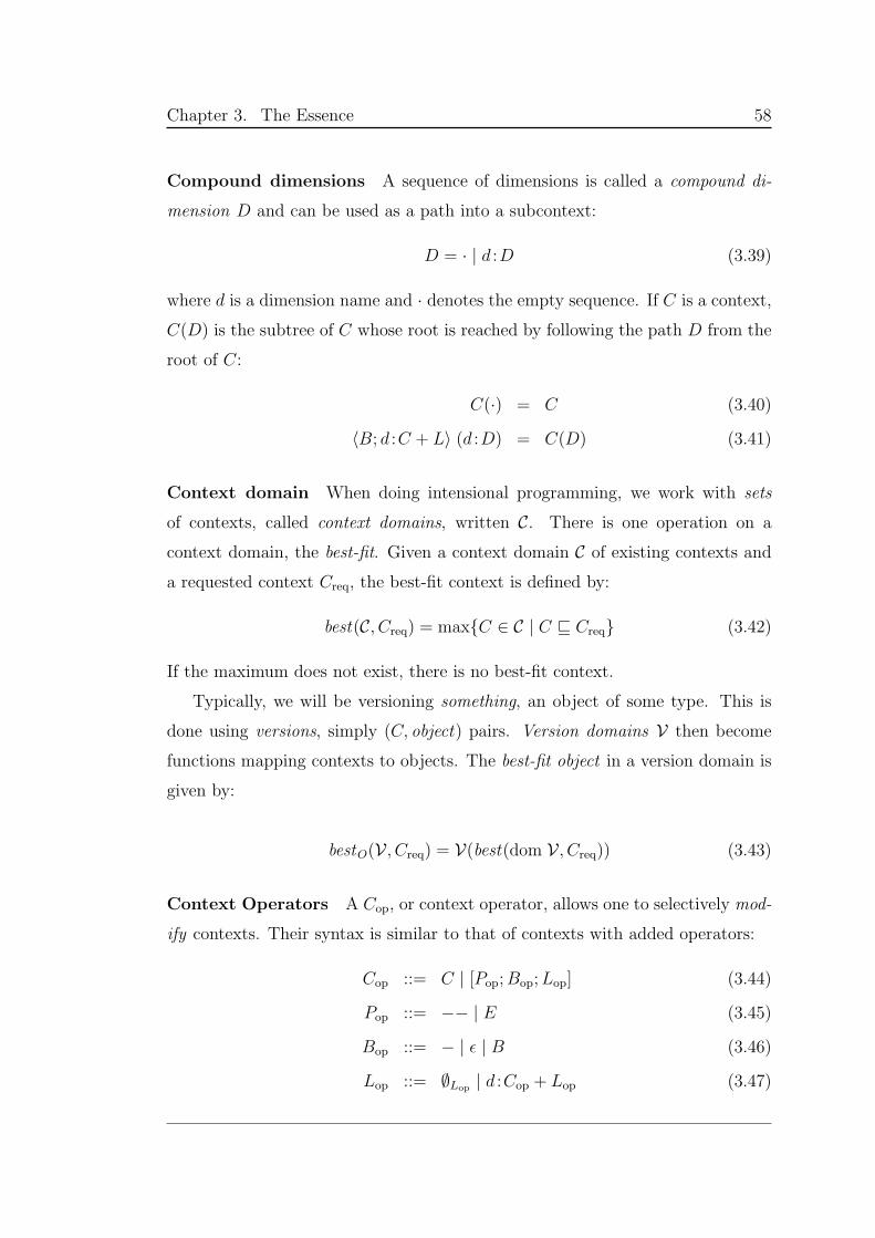
Chapter 3. The Essence 58
Compound dimensions A sequence of dimensions is called a compound di-
mension D and can be used as a path into a subcontext:
D = · | d :D (3.39)
where d is a dimension name and · denotes the empty sequence. If C is a context,
C(D) is the subtree of C whose root is reached by following the path D from the
root of C:
C(·) = C (3.40)
〈B; d :C + L〉 (d :D) = C(D) (3.41)
Context domain When doing intensional programming, we work with sets
of contexts, called context domains, written C. There is one operation on a
context domain, the best-fit. Given a context domain C of existing contexts and
a requested context Creq, the best-fit context is defined by:
best(C, Creq) = maxC ∈ C | C ⊑ Creq (3.42)
If the maximum does not exist, there is no best-fit context.
Typically, we will be versioning something, an object of some type. This is
done using versions, simply (C, object) pairs. Version domains V then become
functions mapping contexts to objects. The best-fit object in a version domain is
given by:
bestO(V , Creq) = V(best(dom V , Creq)) (3.43)
Context Operators A Cop, or context operator, allows one to selectively mod-
ify contexts. Their syntax is similar to that of contexts with added operators:
Cop ::= C | [Pop;Bop;Lop] (3.44)
Pop ::= −− | E (3.45)
Bop ::= − | ǫ | B (3.46)
Lop ::= ∅Lop| d :Cop + Lop (3.47)
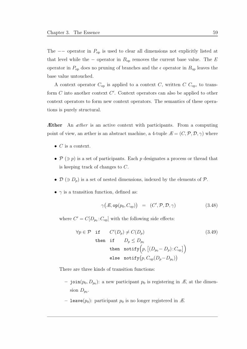
Chapter 3. The Essence 59
The −− operator in Pop is used to clear all dimensions not explicitly listed at
that level while the − operator in Bop removes the current base value. The E
operator in Pop does no pruning of branches and the ǫ operator in Bop leaves the
base value untouched.
A context operator Cop is applied to a context C, written C Cop, to trans-
form C into another context C ′. Context operators can also be applied to other
context operators to form new context operators. The semantics of these opera-
tions is purely structural.
Æther An æther is an active context with participants. From a computing
point of view, an æther is an abstract machine, a 4-tuple Æ = (C,P ,D, γ) where
• C is a context.
• P (∋ p) is a set of participants. Each p designates a process or thread that
is keeping track of changes to C.
• D (∋ Dp) is a set of nested dimensions, indexed by the elements of P .
• γ is a transition function, defined as:
γ(Æ, op(p0, Cop)
)= (C ′,P ,D, γ) (3.48)
where C ′ = C[Dp0 :Cop] with the following side effects:
∀p ∈ P if C ′(Dp) 6= C(Dp)
then if Dp ≤ Dp0
then notify(
p,[(Dp0−Dp) :Cop
])
else notify(p, Cop(Dp−Dp0)
)
(3.49)
There are three kinds of transition functions:
– join(p0, Dp0): a new participant p0 is registering in Æ, at the dimen-
sion Dp0 .
– leave(p0): participant p0 is no longer registered in Æ.
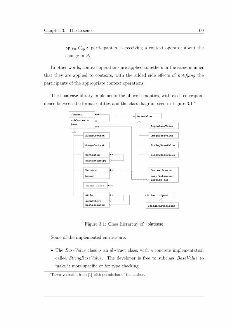
Chapter 3. The Essence 60
– op(p0, Cop): participant p0 is receiving a context operator about the
change in Æ.
In other words, context operations are applied to æthers in the same manner
that they are applied to contexts, with the added side effects of notifying the
participants of the appropriate context operations.
The libintense library implements the above semantics, with close correspon-
dence between the formal entities and the class diagram seen in Figure 3.1.2
AlphaBaseValue
OmegaBaseValue
StringBaseValue
BinaryBaseValue
BaseValue
Participant
BridgeParticipant
subAEthers
AEther
participants
base
Context
subContexts
bound
Bound Class
best(intension)
version set
AlphaContext
OmegaContext
ContextOp
subContextOps
Version ContextDomain
Figure 3.1: Class hierarchy of libintense
Some of the implemented entities are:
• The BaseValue class is an abstract class, with a concrete implementation
called StringBaseValue. The developer is free to subclass BaseValue to
make it more specific or for type checking.
2Taken verbatim from [1] with permission of the author.
Chapter 3. The Essence 61
• Context is the superclass of both AEther and ContextOp, as it is more gen-
eral than the two: An æther is a context with participants; and a context
operation modifies a context. Participant is an abstract class, for the de-
veloper to subclass and implement, to exactly specify how the participant
is to react upon receiving the notification of the change (through a context
operator).
• The class ContextDomain implements best-fit operations and although it
aggregates Context , it is intended to be used with the Version subclass.
Version is simply a Context with an object “bound” behind an Object
reference.
When extending the infrastructure of libintense to new applications, the stan-
dard way is to extend the class hierarchy, subclassing Context and Participant .
This allows specialized functionality for different applications. For example, ijsp
takes this approach, as the needs for Web programming are quite peculiar. For
the Anita Conti Mapping Server, the specialized needs in collaboration require
several subclasses of Participant .
3.9 Intensional Web programming
Java is currently a key language for Web development offering three main tools:
servlets, JSP pages and applets. Servlets are HTTP request-handling objects.
JSP pages are HTML pages with embedded Java code, translated on the fly to
servlets. Applets are mobile chunks of Java code sent to and executed by the
remote browser.
The Apache Tomcat servlet container of the Jakarta project [68, 69], is the
reference implementation for the Sun Java servlet and JSP specification. The JSP
translator is built into the Tomcat’s servlet container, and performs the demand-
driven processing of JSP files (.jsp extension) into their servlet counterparts
(.java extension). In general, if the servlet does not exist or it is older than the
Chapter 3. The Essence 62
JSP counterpart, the servlet is regenerated. A HTTP request to a JSP page is
ultimately redirected to its servlet.
Swoboda created an infrastructure using the Tomcat server and JSP to allow
the sharing of a global context, or parts of it, between users and the Web server
components. The infrastructure provides a means to access the Java libintense
implementation from JSP pages. The Tomcat servlet container in which the JSP
translator resides is multi-threaded. Each individual request is serviced by a
different thread from the pool managed by the container. As such, æthers cannot
be used directly from JSP pages, as each instance of the page might attempt to
update the æther simultaneously, bringing it to inconsistency. Swoboda’s solution
was to subclass both AEther and Participant to a thread-safe variant, such that
only one thread may access any node of the æther at any time. These classes are
put in a package called ijsp (for Intensional JSP).
The package ijsp is designed to allow many users to share the same context
using JSP pages. When one user is following the changes of context made by
another user, he needs to be notified in the browser window of these changes.
For an automatic refresh, Swoboda created an applet infrastructure as a listener
thread for node changes. Subclassed from Participant , ParticipantApplet uses the
context operation and Participant methods to refresh the browser page. On the
server side, the instances of ParticipantApplet (i.e., the different threads listening
to a context change and associated with a browser window) are managed by a
ParticipantServer . This class is implemented to have only one instance, the
thread that manages all the existent instances of ParticipantApplet listening to
the context. It also performs the join() and detach() methods of the participants
from the æther.
This approach has the advantage of respecting the HTTP protocol and does
not use server-push for window refreshing. However, put in Swoboda’s words,
this infrastructure was not trivially implemented because “What is called Web
programming really means programming around the astonishing limitations of
the connectionless HTTP protocol.” [1, p.149]
So far, we have talked about textual intensional documents, and most of the
Chapter 3. The Essence 63
developments in intensionality have been around text and Web pages. What
happens when the document is itself representing a context?
3.10 Maps and intensionality
The map is intrinsically and naturally a multidimensional entity because it de-
pends on a large set of parameters or dimensions, of many kinds. This thesis
considers an electronic map to be an intension, and that specific maps generated
on-demand are the extensions. However, we believe that intensional maps are in
some sense more complex than the intensional documents described in previous
sections, due to the nature of maps.
At one level, of course, a map is a document, so it can be treated as an inten-
sion, like the Web pages created by IHTML and ISE. Parameters can cover aspects
of map design (projection, region), map look (color scheme, scale bar look, image
size), typesetting (language, font description), and output (format, resolution,
printer or screen type). These parameters will all influence the production of the
map, its coloring, its contents, its frame, titles and labels.
Unlike text or software, maps are not representing a sequence of discrete
entities named words, characters or glyphs. A geographical map depicts a physical
area — which is not discrete — and fills that depicted space with different kinds
of abstractions of existing objects (like rivers, mountains, cities, and telephone
poles) and human-made concepts (like political boundaries, weather patterns,
human population). So in sense a map visually presents a context — part of the
globe’s surface — along with certain features linked to that space.
A versioned map is a set of maps that share a context space. The map of Aus-
tralia is an intension of a group of maps whose region is loosely defined between
110 and 115 of longitude, and -45 and -10 of latitude. The set of included
maps may vary according to simple parameters such as color scheme or language;
or may contain significant differences, both in context and content, as used in
thematic maps (state division, vegetation distribution, climate change, . . . ). All
of these maps are versions of the map of Australia.
Chapter 3. The Essence 64
The map-specific context is more than simply the geographical area and the
presentation parameters. According to Marc Monmonier [70], “All maps lie”.
This dictum refers to two different aspects of a map. First, to be of any use, a
map must necessarily hide certain features and exaggerate others. Second, all
geographical maps must project part of a 3-D sphere (the Earth) onto a 2-D map
using a cartographic projection, which also distorts reality in its own manner.
Because of the complexity of a map’s interface, our approach is to create
a intensional Web interface with which a user may manipulate that context,
effectively creating an API between the user and the context. Other APIs to
the context are provided, to the mapping engine, the typesetting system, and the
database management system, in order to create maps according to user requests.
The Web interface also uses the context to support collaboration between
multiple users. Using the interface to manipulate the context, users can create
intensional communities that ensure that as one map-maker makes changes to
maps, the others are aware of the changes being made. The details for these
communities are given in Chapter 4 and the interface is presented in Chapter 7.
The rest of the thesis examines in detail the context and shows how it can be
used to produce ever more context-sensitive maps. Chapter 5 presents the context
space for maps of the world. Chapter 6 focuses on the language dimension, and
shows how even a single dimension can lead to significant new insights when the
whole infrastructure is viewed intensionally.
Chapter 4
Sharing the Context
Browsing together for ideas and knowledge;
collaborating using a Common Medium...
The words ‘sharing’, ‘collaboration’ and ‘community’ have many different mean-
ings in the electronic area. In the Anita Conti Mapping Server, these terms have
a strict technical interpretation: the æther is the center of any exchange. From
the user point of view, sharing is done through the æther; collaboration is done by
having the users take turns in modifying the æther so others can see the changes
(i.e., users actions and interactions), and communities are formed by users shar-
ing the same æther. From the system point of view, applications use the æther as
a mean of interaction and collaborate (share the æther) to achieve the system’s
goals. This creates an intensional community. In addition, both users and ap-
plications share the æther. Users can see what the applications’ parameters are
and applications can run using the latest user requirements.
The Server is implemented to manage multiple, independent æthers, support-
ing separate communities of users. When starting collaboration, new users can
choose to join an existing community or to start up a new one. Each community
has one (human) leader and one or more followers. These roles may be exchanged
depending on the different types of communities. As the leader creates new maps
and changes interface settings (i.e., modifies the sharing æther), all of the users
“listening” are informed about the change, which they may choose to ignore.
65
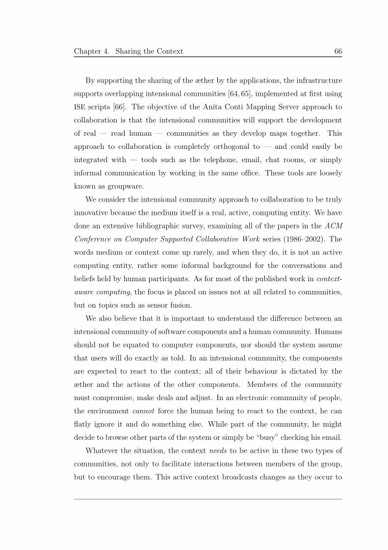
Chapter 4. Sharing the Context 66
By supporting the sharing of the æther by the applications, the infrastructure
supports overlapping intensional communities [64, 65], implemented at first using
ISE scripts [66]. The objective of the Anita Conti Mapping Server approach to
collaboration is that the intensional communities will support the development
of real — read human — communities as they develop maps together. This
approach to collaboration is completely orthogonal to — and could easily be
integrated with — tools such as the telephone, email, chat rooms, or simply
informal communication by working in the same office. These tools are loosely
known as groupware.
We consider the intensional community approach to collaboration to be truly
innovative because the medium itself is a real, active, computing entity. We have
done an extensive bibliographic survey, examining all of the papers in the ACM
Conference on Computer Supported Collaborative Work series (1986–2002). The
words medium or context come up rarely, and when they do, it is not an active
computing entity, rather some informal background for the conversations and
beliefs held by human participants. As for most of the published work in context-
aware computing, the focus is placed on issues not at all related to communities,
but on topics such as sensor fusion.
We also believe that it is important to understand the difference between an
intensional community of software components and a human community. Humans
should not be equated to computer components, nor should the system assume
that users will do exactly as told. In an intensional community, the components
are expected to react to the context; all of their behaviour is dictated by the
æther and the actions of the other components. Members of the community
must compromise, make deals and adjust. In an electronic community of people,
the environment cannot force the human being to react to the context, he can
flatly ignore it and do something else. While part of the community, he might
decide to browse other parts of the system or simply be “busy” checking his email.
Whatever the situation, the context needs to be active in these two types of
communities, not only to facilitate interactions between members of the group,
but to encourage them. This active context broadcasts changes as they occur to
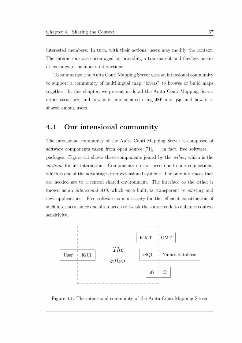
Chapter 4. Sharing the Context 67
interested members. In turn, with their actions, users may modify the context.
The interactions are encouraged by providing a transparent and flawless means
of exchange of member’s interactions.
To summarize, the Anita Conti Mapping Server uses an intensional community
to support a community of multilingual map “lovers” to browse or build maps
together. In this chapter, we present in detail the Anita Conti Mapping Server
æther structure, and how it is implemented using JSP and ijsp, and how it is
shared among users.
4.1 Our intensional community
The intensional community of the Anita Conti Mapping Server is composed of
software components taken from open source [71], — in fact, free software —
packages. Figure 4.1 shows these components joined by the æther, which is the
medium for all interaction. Components do not need one-to-one connections,
which is one of the advantages over extensional systems: The only interfaces that
are needed are to a central shared environment. The interface to the æther is
known as an intensional API, which once built, is transparent to existing and
new applications. Free software is a necessity for the efficient construction of
such interfaces, since one often needs to tweak the source code to enhance context
sensitivity.
____________________
_ _ _ _ _ _ _ _ _ _ _ _ _ _ _ _ _ _ _ _
User iGUI iSQL Names database
iGMT GMT
iΩ Ω
The
æther
Figure 4.1: The intensional community of the Anita Conti Mapping Server

Chapter 4. Sharing the Context 68
The GUI is an intensional Web page that allows the user to access the mapping
server and set the different parameters of map making or Web page look (details
in Chapter 7). It also sets up the sharing environment.
GMT or Generic Mapping Tools [2], is the geographical mapping engine. The
parameters collected from the user as well as values in the æther are the input
to the engine. The base maps are produced with the GMT pscoast function
— using the GMT databases for national borders and water bodies — due to
its wide variation, different input requirements, and impact on the output. One
particularly interesting input parameter is the geographical projection. Chapter 5
explains in detail how this intensional API is implemented.
The names database contains geographical names in different languages. Ω [3]
is the typesetting engine used for pretty printing of labels on the map, using
parameters from the æther, such as language and script, with encoded strings
from the names database. Chapter 6 describes how the names of geographical
places become intensions and how Ω prints the multilingual strings searched and
found in a names database through an iAPI to SQL.
4.2 Collaborative mapping
Now that it is clear that intensional collaboration takes place using an æther and
that this æther becomes the core of the system, we need to initialize it. The
difficulty lies in defining the correct context space (§3.4, page 44) for the system,
so that it precisely describes how users, their communities and their context are
represented, as well as how interactions should take place.
The values in the æther at any given moment represent an instance of the sys-
tem, a possible world, and given a snapshot of the æther (i.e., a context operator),
we may reproduce that exact instance. By context space here, we refer to the
description of all the possible values that all the possible dimensions can take,
along with the overall tree structure. In turn, these dimensions must provide
all the relevant information about parameters and states of each of the software
components, users and community groups at a given instant. The context space
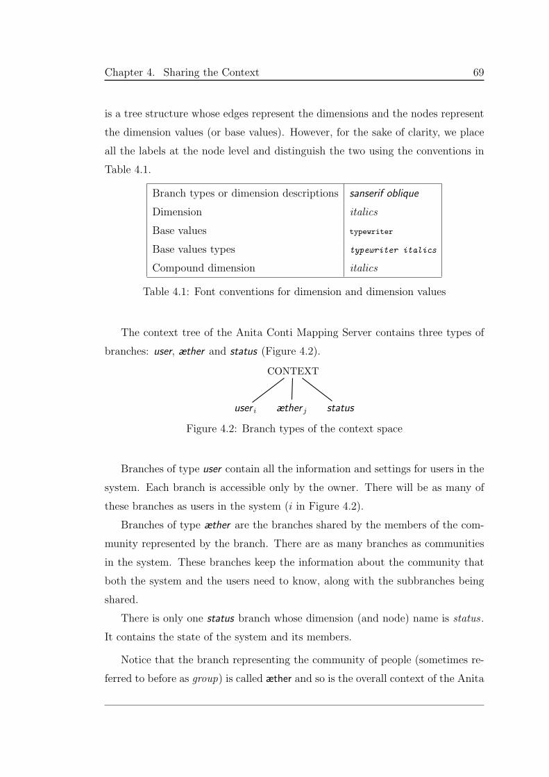
Chapter 4. Sharing the Context 69
is a tree structure whose edges represent the dimensions and the nodes represent
the dimension values (or base values). However, for the sake of clarity, we place
all the labels at the node level and distinguish the two using the conventions in
Table 4.1.
Branch types or dimension descriptions sanserif oblique
Dimension italics
Base values typewriter
Base values types typewriter italics
Compound dimension italics
Table 4.1: Font conventions for dimension and dimension values
The context tree of the Anita Conti Mapping Server contains three types of
branches: user, æther and status (Figure 4.2).
CONTEXT
user i æther j status
Figure 4.2: Branch types of the context space
Branches of type user contain all the information and settings for users in the
system. Each branch is accessible only by the owner. There will be as many of
these branches as users in the system (i in Figure 4.2).
Branches of type æther are the branches shared by the members of the com-
munity represented by the branch. There are as many branches as communities
in the system. These branches keep the information about the community that
both the system and the users need to know, along with the subbranches being
shared.
There is only one status branch whose dimension (and node) name is status .
It contains the state of the system and its members.
Notice that the branch representing the community of people (sometimes re-
ferred to before as group) is called æther and so is the overall context of the Anita
Chapter 4. Sharing the Context 70
Conti Mapping Server. In this text, they are distinguished by the different font.
The branch is called that way for historical reasons: initially an æther was to be
an active context to facilitate interactions between people. It was then discovered
that communities of computer components (later called intensional communities)
also needed the æther, and in fact, the community of people needs the entire
intensional community, not just the æther. Hence, from the implementation and
conceptual points of view, the tree structure is an æther, as implemented in
libintense (§3.8 and Figure 3.1, page 60) but the branch kept the name.
The initialization and establishment of the community of people in the Anita
Conti Mapping Server is done through the server’s Web page, implemented using
ijsp (§3.9). This package provides a means to access and modify the Æther of
the libintense implementation from JSP pages. Most of the GUI is discussed in
later chapters, but here we will only refer to the parts concerning collaboration
and group set up. Figure 4.3 shows the JSP scripts involved in creating the Web
pages that handle user communities.
startUp.jsp
anita.jsp
getUserName.jsp
processShare.jsp
getNewAetherId.jsp
newAether.jsp
createAether.jsp
join.jsp
listener.jsp
listenerAnita.jsp
Figure 4.3: Workflow of JSP pages for the Sharing option
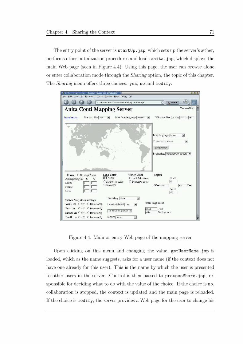
Chapter 4. Sharing the Context 71
The entry point of the server is startUp.jsp, which sets up the server’s æther,
performs other initialization procedures and loads anita.jsp, which displays the
main Web page (seen in Figure 4.4). Using this page, the user can browse alone
or enter collaboration mode through the Sharing option, the topic of this chapter.
The Sharing menu offers three choices: yes, no and modify.
Figure 4.4: Main or entry Web page of the mapping server
Upon clicking on this menu and changing the value, getUserName.jsp is
loaded, which as the name suggests, asks for a user name (if the context does not
have one already for this user). This is the name by which the user is presented
to other users in the server. Control is then passed to processShare.jsp, re-
sponsible for deciding what to do with the value of the choice. If the choice is no,
collaboration is stopped, the context is updated and the main page is reloaded.
If the choice is modify, the server provides a Web page for the user to change his
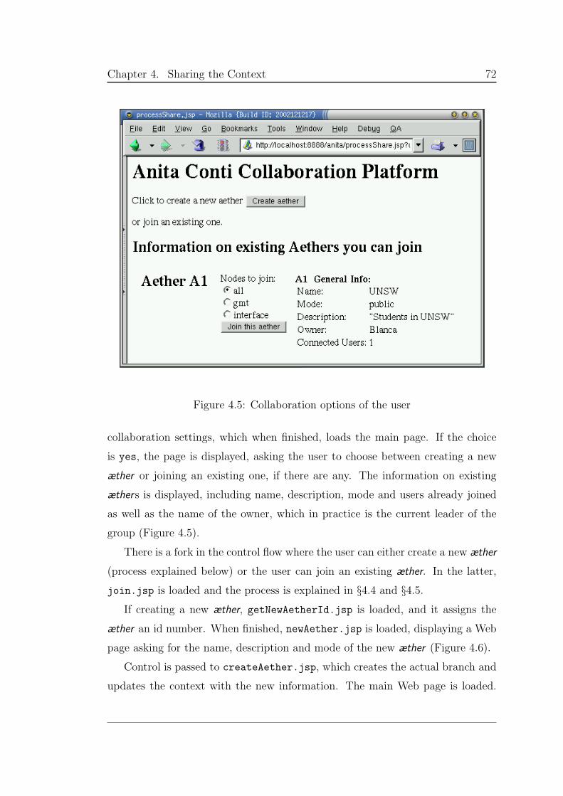
Chapter 4. Sharing the Context 72
Figure 4.5: Collaboration options of the user
collaboration settings, which when finished, loads the main page. If the choice
is yes, the page is displayed, asking the user to choose between creating a new
æther or joining an existing one, if there are any. The information on existing
æthers is displayed, including name, description, mode and users already joined
as well as the name of the owner, which in practice is the current leader of the
group (Figure 4.5).
There is a fork in the control flow where the user can either create a new æther
(process explained below) or the user can join an existing æther. In the latter,
join.jsp is loaded and the process is explained in §4.4 and §4.5.
If creating a new æther, getNewAetherId.jsp is loaded, and it assigns the
æther an id number. When finished, newAether.jsp is loaded, displaying a Web
page asking for the name, description and mode of the new æther (Figure 4.6).
Control is passed to createAether.jsp, which creates the actual branch and
updates the context with the new information. The main Web page is loaded.
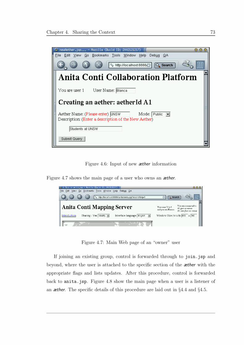
Chapter 4. Sharing the Context 73
Figure 4.6: Input of new æther information
Figure 4.7 shows the main page of a user who owns an æther.
Figure 4.7: Main Web page of an “owner” user
If joining an existing group, control is forwarded through to join.jsp and
beyond, where the user is attached to the specific section of the æther with the
appropriate flags and lists updates. After this procedure, control is forwarded
back to anita.jsp. Figure 4.8 show the main page when a user is a listener of
an æther. The specific details of this procedure are laid out in §4.4 and §4.5.
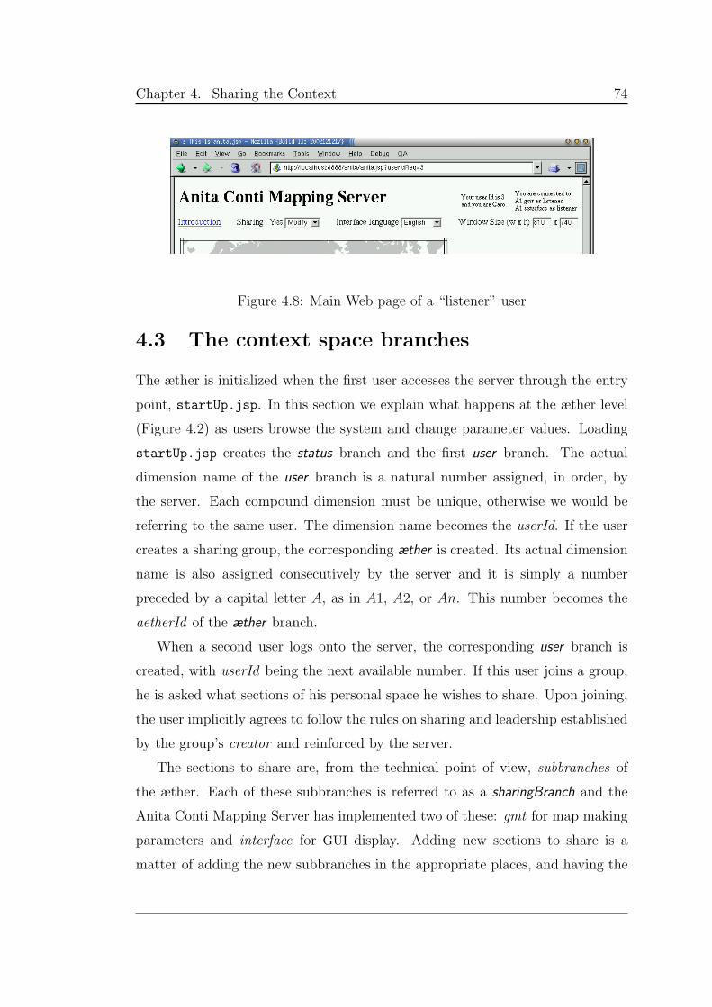
Chapter 4. Sharing the Context 74
Figure 4.8: Main Web page of a “listener” user
4.3 The context space branches
The æther is initialized when the first user accesses the server through the entry
point, startUp.jsp. In this section we explain what happens at the æther level
(Figure 4.2) as users browse the system and change parameter values. Loading
startUp.jsp creates the status branch and the first user branch. The actual
dimension name of the user branch is a natural number assigned, in order, by
the server. Each compound dimension must be unique, otherwise we would be
referring to the same user. The dimension name becomes the userId. If the user
creates a sharing group, the corresponding æther is created. Its actual dimension
name is also assigned consecutively by the server and it is simply a number
preceded by a capital letter A, as in A1, A2, or An. This number becomes the
aetherId of the æther branch.
When a second user logs onto the server, the corresponding user branch is
created, with userId being the next available number. If this user joins a group,
he is asked what sections of his personal space he wishes to share. Upon joining,
the user implicitly agrees to follow the rules on sharing and leadership established
by the group’s creator and reinforced by the server.
The sections to share are, from the technical point of view, subbranches of
the æther. Each of these subbranches is referred to as a sharingBranch and the
Anita Conti Mapping Server has implemented two of these: gmt for map making
parameters and interface for GUI display. Adding new sections to share is a
matter of adding the new subbranches in the appropriate places, and having the
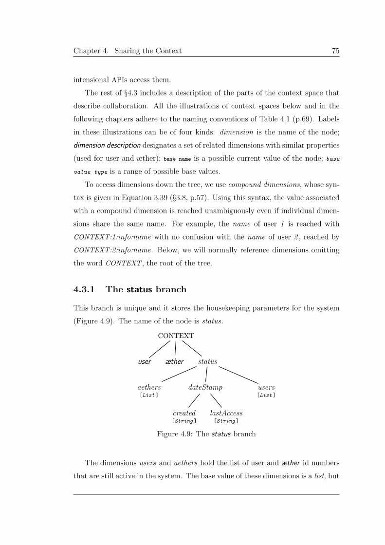
Chapter 4. Sharing the Context 75
intensional APIs access them.
The rest of §4.3 includes a description of the parts of the context space that
describe collaboration. All the illustrations of context spaces below and in the
following chapters adhere to the naming conventions of Table 4.1 (p.69). Labels
in these illustrations can be of four kinds: dimension is the name of the node;
dimension description designates a set of related dimensions with similar properties
(used for user and æther); base name is a possible current value of the node; base
value type is a range of possible base values.
To access dimensions down the tree, we use compound dimensions, whose syn-
tax is given in Equation 3.39 (§3.8, p.57). Using this syntax, the value associated
with a compound dimension is reached unambiguously even if individual dimen-
sions share the same name. For example, the name of user 1 is reached with
CONTEXT:1:info:name with no confusion with the name of user 2 , reached by
CONTEXT:2:info:name. Below, we will normally reference dimensions omitting
the word CONTEXT , the root of the tree.
4.3.1 The status branch
This branch is unique and it stores the housekeeping parameters for the system
(Figure 4.9). The name of the node is status .
CONTEXT
user æther status
aethers[List ]
dateStamp
created[String ]
lastAccess[String ]
users[List ]
Figure 4.9: The status branch
The dimensions users and aethers hold the list of user and æther id numbers
that are still active in the system. The base value of these dimensions is a list, but
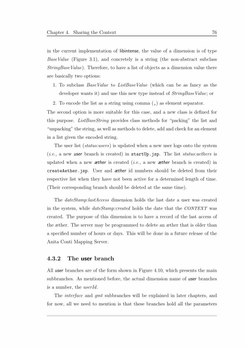
Chapter 4. Sharing the Context 76
in the current implementation of libintense, the value of a dimension is of type
BaseValue (Figure 3.1), and concretely is a string (the non-abstract subclass
StringBaseValue). Therefore, to have a list of objects as a dimension value there
are basically two options:
1. To subclass BaseValue to ListBaseValue (which can be as fancy as the
developer wants it) and use this new type instead of StringBaseValue; or
2. To encode the list as a string using comma (,) as element separator.
The second option is more suitable for this case, and a new class is defined for
this purpose. ListBaseString provides class methods for “packing” the list and
“unpacking” the string, as well as methods to delete, add and check for an element
in a list given the encoded string.
The user list (status:users) is updated when a new user logs onto the system
(i.e., a new user branch is created) in startUp.jsp. The list status:aethers is
updated when a new æther is created (i.e., a new æther branch is created) in
createAether.jsp. User and æther id numbers should be deleted from their
respective list when they have not been active for a determined length of time.
(Their corresponding branch should be deleted at the same time).
The dateStamp:lastAccess dimension holds the last date a user was created
in the system, while dateStamp:created holds the date that the CONTEXT was
created. The purpose of this dimension is to have a record of the last access of
the æther. The server may be programmed to delete an æther that is older than
a specified number of hours or days. This will be done in a future release of the
Anita Conti Mapping Server.
4.3.2 The user branch
All user branches are of the form shown in Figure 4.10, which presents the main
subbranches. As mentioned before, the actual dimension name of user branches
is a number, the userId .
The interface and gmt subbranches will be explained in later chapters, and
for now, all we need to mention is that these branches hold all the parameters
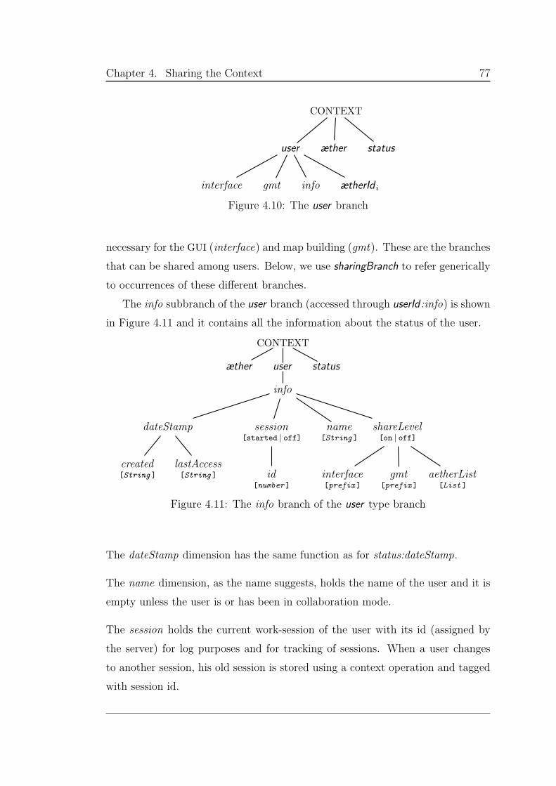
Chapter 4. Sharing the Context 77
CONTEXT
user
interface gmt info ætherId i
æther status
Figure 4.10: The user branch
necessary for the GUI (interface) and map building (gmt). These are the branches
that can be shared among users. Below, we use sharingBranch to refer generically
to occurrences of these different branches.
The info subbranch of the user branch (accessed through userId :info) is shown
in Figure 4.11 and it contains all the information about the status of the user.
CONTEXT
æther user
info
dateStamp
created[String ]
lastAccess[String ]
session[started | off]
id[number ]
name[String ]
shareLevel[on | off]
interface[prefix ]
gmt[prefix ]
aetherList[List ]
status
Figure 4.11: The info branch of the user type branch
The dateStamp dimension has the same function as for status:dateStamp.
The name dimension, as the name suggests, holds the name of the user and it is
empty unless the user is or has been in collaboration mode.
The session holds the current work-session of the user with its id (assigned by
the server) for log purposes and for tracking of sessions. When a user changes
to another session, his old session is stored using a context operation and tagged
with session id.
Chapter 4. Sharing the Context 78
The shareLevel branch stores the collaboration parameters of the user with infor-
mation about what to share (or not). The possible base values of the dimension
are on and off. With off, the rest of the branch is irrelevant since (obviously)
this user is not collaborating. The whole branch below is ignored. When the
value is on, the user is sharing and all the existing subbranches (aetherList , gmt
and interface) of the node describe the collaboration status of the user.
aetherList : It holds the list of the æthers to which this user is connected in
listening mode. This base value is a string encoding a list, manipulated using the
ListBaseString class (page 76).
gmt and interface: These dimensions take a base value of type prefix which
indicates where to look for map and GUI parameters. (If the user is “listening”
to an æther the values to use for that branch are not his own, but the æther ’s.)
If the prefix is not empty, it holds the id number of the æther that this user
is listening to, values are looked for in userId:aetherId:sharingBranch. If empty,
values are loaded from the personal branch (userId:sharingBranch)
For example, if user 3 is a “listener” in gmt from A1 , and is the “owner”
of interface for A2 , then the prefix for gmt (i.e., the 3:info:shareLevel:gmt base
value) is A1, and for interface (i.e., the base value of 3:info:shareLevel:interface)
is the empty string. The server looks for map and GUI parameters for user 3 in
3:A1:gmt and 3:interface respectively.
The userId:ætherId subbranch is shown in Figure 4.12 and it is implicitly men-
tioned in the previous paragraph. There will be as many of these branches as
there are æthers this user is connected to in listening mode (in other words as
many elements as in the userId :info:shareLevel:aetherList list). So, 1:A1 indi-
cates that user 1 is connected to æther A1 and one of the members of the list
stored in 1:info:shareLevel:aethersList is A1. This node has three subbranches:
info, gmt and interface.
The branch info in userId:ætherId:info has at most two branches containing in-
formation about the sharingBranch’es (and named after them of course). Their
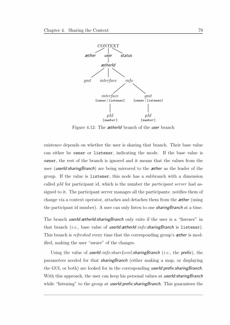
Chapter 4. Sharing the Context 79
CONTEXT
æther user
ætherId
gmt interface info
interface[owner | listener]
pId[number ]
gmt[owner | listener]
pId[number ]
status
Figure 4.12: The ætherId branch of the user branch
existence depends on whether the user is sharing that branch. Their base value
can either be owner or listener, indicating the mode. If the base value is
owner, the rest of the branch is ignored and it means that the values from the
user (userId:sharingBranch) are being mirrored to the æther as the leader of the
group. If the value is listener, this node has a subbranch with a dimension
called pId for participant id, which is the number the participant server had as-
signed to it. The participant server manages all the participants: notifies them of
change via a context operator, attaches and detaches them from the æther (using
the participant id number). A user can only listen to one sharingBranch at a time.
The branch userId:ætherId:sharingBranch only exits if the user is a “listener” in
that branch (i.e., base value of userId:ætherId :info:sharingBranch is listener).
This branch is refreshed every time that the corresponding group’s æther is mod-
ified, making the user “aware” of the changes.
Using the value of userId :info:shareLevel:sharingBranch (i.e., the prefix), the
parameters needed for that sharingBranch (either making a map, or displaying
the GUI, or both) are looked for in the corresponding userId:prefix:sharingBranch.
With this approach, the user can keep his personal values at userId:sharingBranch
while “listening” to the group at userId:prefix:sharingBranch. This guarantees the
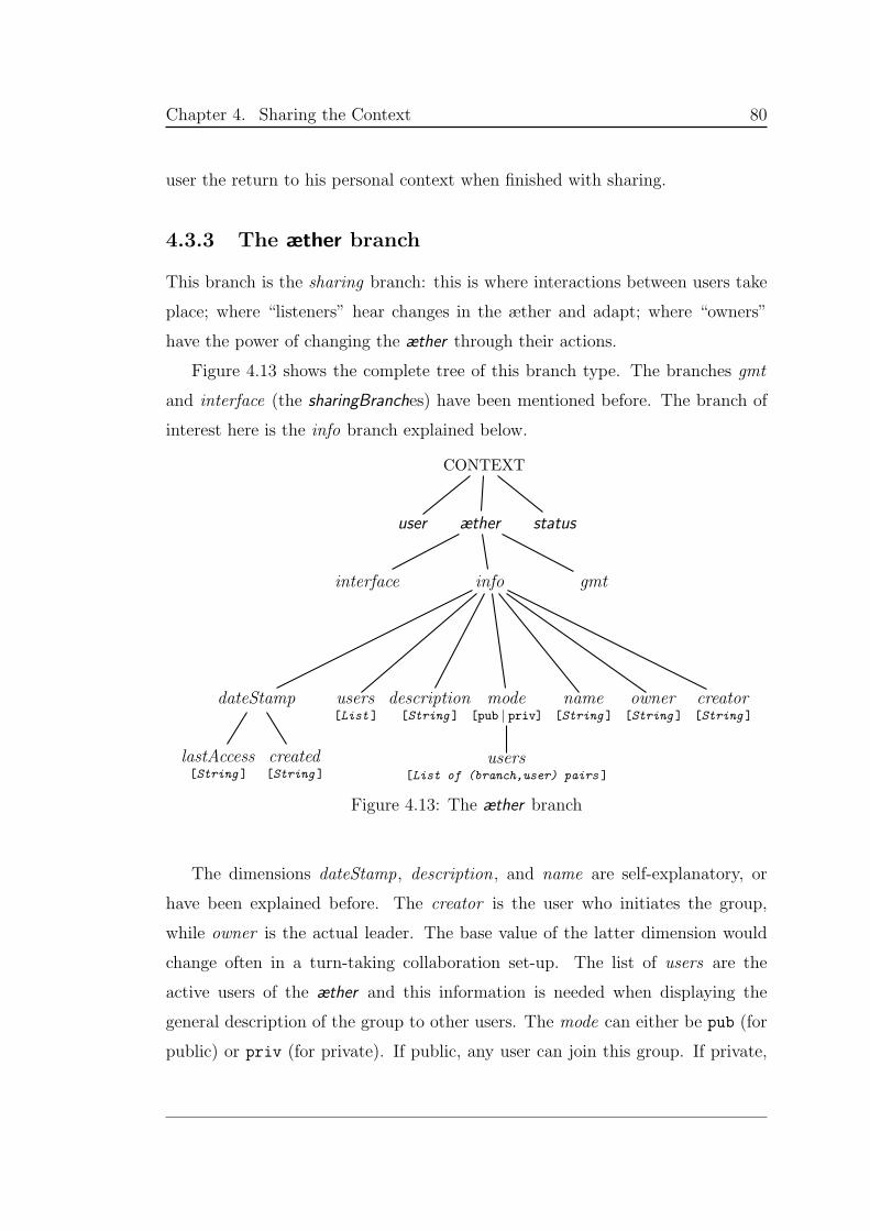
Chapter 4. Sharing the Context 80
user the return to his personal context when finished with sharing.
4.3.3 The æther branch
This branch is the sharing branch: this is where interactions between users take
place; where “listeners” hear changes in the æther and adapt; where “owners”
have the power of changing the æther through their actions.
Figure 4.13 shows the complete tree of this branch type. The branches gmt
and interface (the sharingBranches) have been mentioned before. The branch of
interest here is the info branch explained below.
CONTEXT
user æther
interface info
dateStamp
lastAccess[String ]
created[String ]
users[List ]
description[String ]
mode[pub | priv]
users[List of (branch,user) pairs ]
name[String ]
owner[String ]
creator[String ]
gmt
status
Figure 4.13: The æther branch
The dimensions dateStamp, description, and name are self-explanatory, or
have been explained before. The creator is the user who initiates the group,
while owner is the actual leader. The base value of the latter dimension would
change often in a turn-taking collaboration set-up. The list of users are the
active users of the æther and this information is needed when displaying the
general description of the group to other users. The mode can either be pub (for
public) or priv (for private). If public, any user can join this group. If private,
Chapter 4. Sharing the Context 81
the creator of the group must enter a list of the users and the branch they are
allowed to join. The list is stored in ætherId :info:mode:users.
Most of these parameters are updated when the æther branch is created,
except owner which can change quite frequently if all the group members have
the same privileges and can modify the æther. This scenario happens in real
collaboration where all members have input into the process.
So far we have talked about shared æther branches, but have not seen them
in action. We have also talked about “listeners” and “owners” of groups or
æthers, but have not mentioned how are they hearing and modifying the æther.
In Chapter 3 we discussed the Participant as being a piece of code attached to a
node of an æther, which is executed when the branch off that node has changed.
In libintense, the Participant class is abstract, to be subclassed tailored to each
application.
Below we explain which needs this participant must fulfill in the Anita Conti
Mapping Server and how the subclass of Participant is implemented.
4.4 Participants
Section 3.8 (page 59) formally describes æther and participant. For the context
of the Anita Conti Mapping Server, the æther is the core that holds the system
together and makes it dynamic. The participant is registered at a node of the
æther and is activated when there changes are made, mostly related to user’s
actions.
Some of the methods of the abstract class Participant are: join(æther), to
join the given æther (notice that a branch of an existing æther is also an æther);
leave(), to leave the currently-joined æther; and opNotify(), to notify the partic-
ipant of a context operation, generated as a product of a change in that æther.
In the previous section we described the sharingBranch’es. These are equivalent
to sections or themes (or whatever the implementer wants to called them), that
the user can share. In practice, this means that for each shared branch, there is
a participant attached to that branch, sensitive to any changes in that branch.
Chapter 4. Sharing the Context 82
In this server, a participant must be able to fulfill one of two functions: owner
and listener. The actions of the human owner of an æther are propagated by the
corresponding owner participant, which modifies the sharingBranch in the æther
branch. This change triggers the listener participant of users listening to the
æther, which modifies the context of the user to show the change
To create these participants, two new subclasses have been implemented:
OwnerParticipant and ListenerParticipant .
The function of the OwnerParticipant is to upload to the æther the changes to
the context of the user in the selected branches. This participant is registered at
userId:sharingBranch; when a change occurs, the corresponding context operation
is applied to ætherId:sharingBranch. The joining of this participant happens in
createAether.jsp.
The role of the ListenerParticipant is to copy the changes from the selected
branches of the æther into the user’s context. This time, the participant is regis-
tered at ætherId:sharingBranch; when a change occurs, the context operation (of
the change) is applied to the userId:ætherId:sharingBranch node. For a listener, the
system will take the values of the sharingBranch from userId:ætherId:sharingBranch.
This participant is registered in the æther in join.jsp.
At server level, participants are stored in a hash table, which is stored in
the Tomcat application container. The key to the hash is the participant name,
which is encoded as follows: aetherId-userId-sharingBranch-O | L. When
a participant leaves, the entry must be deleted from the hash, and the leave()
method must be called, using the Pid base value.
Implicitly we have made the distinction between users and participants. Ex-
plicitly, a participant is a piece of software, a member of the intensional commu-
nity, while the user is a human. There may be more than one participant per
user and in fact, there can be as many participants as there are sharingBranches.
This scheme gives flexibility to the developer as well as to the user. A user may
want to share only values of map making, while keeping the look of his screen
personal (i.e., by disallowing other users to change interface values).
This implementation provides the platform for context update of both listeners
Chapter 4. Sharing the Context 83
and owners in a group. It does not, however, deal with automatic refresh of the
browser window. All that is needed is a listening thread or an open connection
associated with the window, which would reload the page when a change occurs.
Designing this part was however particularly difficult due to the stateless state
of http. The mechanism used is the Java applet.
4.5 Applet participant
Based on an experimental part of Swoboda’s PhD, the Anita Conti Mapping
Server provides an applet infrastructure to deal with http’s stateless nature. Al-
though his implementation is the principal model, it presents two main limitations
when applied to the mapping server: In his model, (1) There is no sharing of sec-
tions of the æther, users share the complete context; and (2) The infrastructure
assumes that users are always collaborating (the context is controlled by the ap-
plet). In this setting, there is very little room for personal preferences. The new
implementation needed more flexibility to adjust to the more complex nature of
the server’s context space and its components.
The applet participant in the server is in charge only of window refreshing;
collaboration is left to OwnerParticipant and ListenerParticipant , which are ex-
plained in the previous section. This “division of labor” is appreciated by users
whose browser or computer do not support applets. These users can always be
part of a group and systematically hit the refresh button in their browser to have
the same effect as the applet.
The applet is invoked when the user chooses to join a community (i.e., an
æther) off the Sharing menu in the main Web page of the server. Section 4.2
explained the process involved in creating a new community. Here we explain the
other side of the fork, when the user is joining an existing one.
Context updates, including of lists, take place in join.jsp. The current
window is named ListeneruserId and becomes the main user’s main window. From
join.jsp, listener.jsp is invoked in a new window as many times as there
are sharingBranch’es to connect to. Each new window is called “sharingBranch
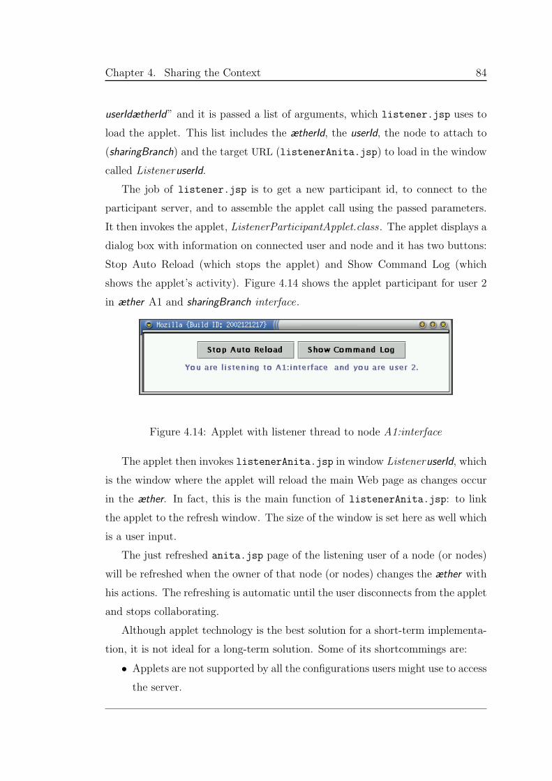
Chapter 4. Sharing the Context 84
userIdætherId” and it is passed a list of arguments, which listener.jsp uses to
load the applet. This list includes the ætherId, the userId, the node to attach to
(sharingBranch) and the target URL (listenerAnita.jsp) to load in the window
called ListeneruserId.
The job of listener.jsp is to get a new participant id, to connect to the
participant server, and to assemble the applet call using the passed parameters.
It then invokes the applet, ListenerParticipantApplet.class. The applet displays a
dialog box with information on connected user and node and it has two buttons:
Stop Auto Reload (which stops the applet) and Show Command Log (which
shows the applet’s activity). Figure 4.14 shows the applet participant for user 2
in æther A1 and sharingBranch interface.
Figure 4.14: Applet with listener thread to node A1:interface
The applet then invokes listenerAnita.jsp in window ListeneruserId, which
is the window where the applet will reload the main Web page as changes occur
in the æther. In fact, this is the main function of listenerAnita.jsp: to link
the applet to the refresh window. The size of the window is set here as well which
is a user input.
The just refreshed anita.jsp page of the listening user of a node (or nodes)
will be refreshed when the owner of that node (or nodes) changes the æther with
his actions. The refreshing is automatic until the user disconnects from the applet
and stops collaborating.
Although applet technology is the best solution for a short-term implementa-
tion, it is not ideal for a long-term solution. Some of its shortcommings are:
• Applets are not supported by all the configurations users might use to access
the server.
Chapter 4. Sharing the Context 85
• There is possibly a requirement for a Java plug-in, especially for Java Swing
components.
• Applets offer no file access (for security reasons).
• This technology cannot handle the functionality of a large application,
therefore there is no scalability.
• Poor performance may occur when running multiple applets in the same
window.
From the implementation point of view, a “listener” has two participants per
sharingBranch. The first one is the ListenerParticipant which is in charge of
updating the user’s context from a sharingBranch in the æther. The second one is
the ListenerParticipantApplet , which is in charge of refreshing the user browser’s
window when the sharingBranch of the æther changes.
4.6 Summary
The collaboration infrastructure described above is an example of how we believe
such frameworks should be built. Although the system could be made much more
sophisticated, we believe that the general framework is correct. In particular, the
ability for a single user to follow slices of several active æthers is applicable to far
more than simply building collaborative Web interfaces.
Chapter 5
The Mapping Engine
Maps
breakdown our inhibitions, stimulate our glands,
stir our imagination and loosen our tongues.
Sauer, 1956
The Anita Conti Mapping Server is an online server, whose current mapping
engine is a subset of the Generic Mapping Tools (GMT) software suite from the
University of Hawaii. This chapter presents in detail the parts of GMT that are
used by the server, along with their intensional API.
Since GMT is free software, it contributes to the phenomenon described by
Morrison [72] as the “democratization of cartography”. He states that “using
electronic technology, no longer does the map user depend on what the cartog-
rapher decides to put on a map. Today the user is the cartographer. . . users are
now able to produce analyses and visualizations at will to any accuracy standard
that satisfies them”.
The best cartography has always been in the hands of a privileged few. Used
as many as 9000 years ago in India, and in every subsequent empire, maps of
the known world have always been preciously guarded, since knowing where the
lands and oceans were meant power and wealth.
Even today, the best data for cartography is either costly or classified. Nev-
ertheless, the situation is changing. The common user now has access to the
86
Chapter 5. The Mapping Engine 87
Internet, computerized map generators, and electronic collections of data to re-
place the cartographer, who previously had the unique power to design maps.
Despite limitations, this power is becoming available to the ordinary user.
And when tools such as GMT are freely available, the difference in the basic
software used by ordinary users and by large institutions is no longer significant.
This chapter presents in detail the context space designed to manage the
GMT pscoast command, which produces coast and political boundary outlines
for maps. We begin with an introduction to the GMT suite (§5.1) and explain its
limitations for online use, due to its inability to handle pervasive runtime configu-
ration management. The core of the chapter consists of the sections on mapping
projections (§5.2) and on mapping frames and grids (§5.4), which themselves
provide a context for how data being mapped will be presented. Because we are
presenting a new programming paradigm, ijsp code will be given throughout the
chapter.
5.1 An introduction to GMT and pscoast
The best initial presentation of GMT is given by the authors themselves:
GMT is an open source collection of ˜60 tools for manipulating ge-
ographic and Cartesian data sets (including filtering, trend fitting,
gridding, projecting, etc.) and producing Encapsulated PostScript File
(EPS) illustrations ranging from simple x-y plots through contour
maps to artificially illuminated surfaces and 3-D perspective views.
GMT supports ˜30 map projections and transformations and comes
with support data such as coastlines, rivers, and political boundaries.
GMT is developed and maintained by Paul Wessel and Walter H. F.
Smith and partly supported by the National Science Foundation. It
is released under the GNU General Public License.
The two programs that concern us are pscoast, which produces a GMT layer
plotting continents, shorelines, rivers and political boundaries, and pstext, which
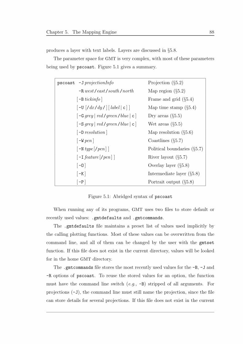
Chapter 5. The Mapping Engine 88
produces a layer with text labels. Layers are discussed in §5.8.
The parameter space for GMT is very complex, with most of these parameters
being used by pscoast. Figure 5.1 gives a summary.
pscoast -J projectionInfo Projection (§5.2)
-Rwest /east /south /north Map region (§5.2)
[ -B tickinfo ] Frame and grid (§5.4)
[ -U [/dx /dy / ] [ label | c ] ] Map time stamp (§5.4)
[ -G grey | red /green /blue | c ] Dry areas (§5.5)
[ -S grey | red /green /blue | c ] Wet areas (§5.5)
[ -D resolution ] Map resolution (§5.6)
[ -W pen ] Coastlines (§5.7)
[ -N type [/pen ] ] Political boundaries (§5.7)
[ -I feature [/pen ] ] River layout (§5.7)
[ -O ] Overlay layer (§5.8)
[ -K ] Intermediate layer (§5.8)
[ -P ] Portrait output (§5.8)
Figure 5.1: Abridged syntax of pscoast
When running any of its programs, GMT uses two files to store default or
recently used values: .gmtdefaults and .gmtcommands.
The .gmtdefaults file maintains a preset list of values used implicitly by
the calling plotting functions. Most of these values can be overwritten from the
command line, and all of them can be changed by the user with the gmtset
function. If this file does not exist in the current directory, values will be looked
for in the home GMT directory.
The .gmtcommands file stores the most recently used values for the -B, -J and
-R options of pscoast. To reuse the stored values for an option, the function
must have the command line switch (e.g., -B) stripped of all arguments. For
projections (-J), the command line must still name the projection, since the file
can store details for several projections. If this file does not exist in the current
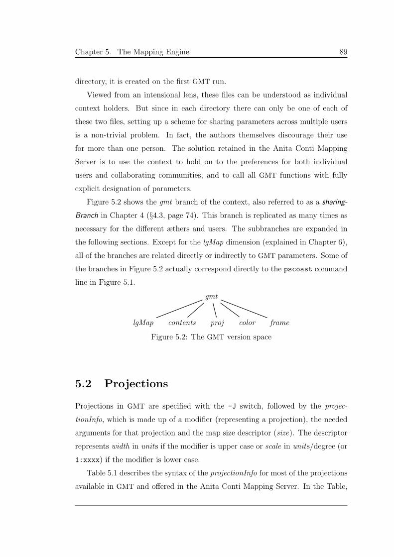
Chapter 5. The Mapping Engine 89
directory, it is created on the first GMT run.
Viewed from an intensional lens, these files can be understood as individual
context holders. But since in each directory there can only be one of each of
these two files, setting up a scheme for sharing parameters across multiple users
is a non-trivial problem. In fact, the authors themselves discourage their use
for more than one person. The solution retained in the Anita Conti Mapping
Server is to use the context to hold on to the preferences for both individual
users and collaborating communities, and to call all GMT functions with fully
explicit designation of parameters.
Figure 5.2 shows the gmt branch of the context, also referred to as a sharing-
Branch in Chapter 4 (§4.3, page 74). This branch is replicated as many times as
necessary for the different æthers and users. The subbranches are expanded in
the following sections. Except for the lgMap dimension (explained in Chapter 6),
all of the branches are related directly or indirectly to GMT parameters. Some of
the branches in Figure 5.2 actually correspond directly to the pscoast command
line in Figure 5.1.
gmt
lgMap contents proj color frame
Figure 5.2: The GMT version space
5.2 Projections
Projections in GMT are specified with the -J switch, followed by the projec-
tionInfo, which is made up of a modifier (representing a projection), the needed
arguments for that projection and the map size descriptor (size). The descriptor
represents width in units if the modifier is upper case or scale in units/degree (or
1:xxxx) if the modifier is lower case.
Table 5.1 describes the syntax of the projectionInfo for most of the projections
available in GMT and offered in the Anita Conti Mapping Server. In the Table,
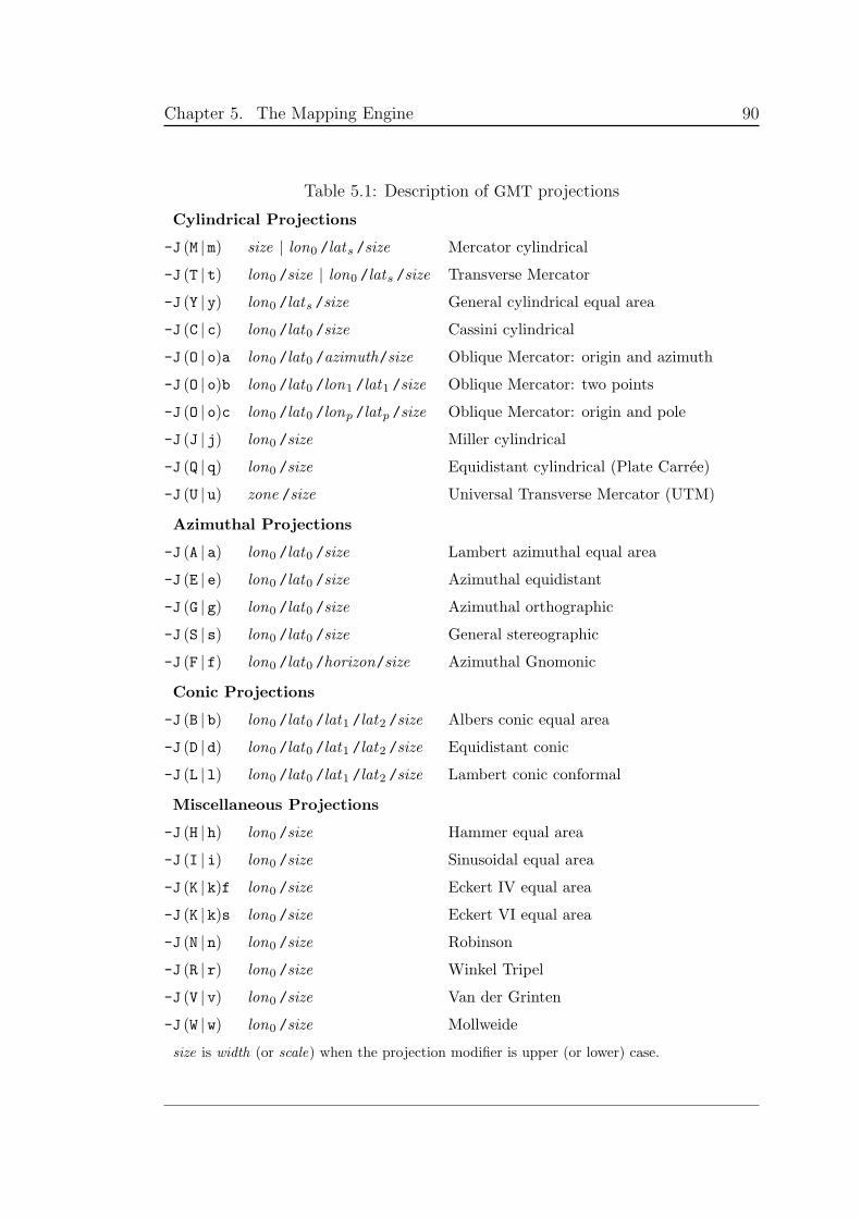
Chapter 5. The Mapping Engine 90
Table 5.1: Description of GMT projections
Cylindrical Projections
-J (M | m) size | lon0 /lats /size Mercator cylindrical
-J (T | t) lon0 /size | lon0 /lats /size Transverse Mercator
-J (Y | y) lon0 /lats /size General cylindrical equal area
-J (C | c) lon0 /lat0 /size Cassini cylindrical
-J (O | o)a lon0 /lat0 /azimuth/size Oblique Mercator: origin and azimuth
-J (O | o)b lon0 /lat0 /lon1 /lat1 /size Oblique Mercator: two points
-J (O | o)c lon0 /lat0 /lonp /latp /size Oblique Mercator: origin and pole
-J (J | j) lon0 /size Miller cylindrical
-J (Q | q) lon0 /size Equidistant cylindrical (Plate Carree)
-J (U | u) zone /size Universal Transverse Mercator (UTM)
Azimuthal Projections
-J (A | a) lon0 /lat0 /size Lambert azimuthal equal area
-J (E | e) lon0 /lat0 /size Azimuthal equidistant
-J (G | g) lon0 /lat0 /size Azimuthal orthographic
-J (S | s) lon0 /lat0 /size General stereographic
-J (F | f) lon0 /lat0 /horizon/size Azimuthal Gnomonic
Conic Projections
-J (B | b) lon0 /lat0 /lat1 /lat2 /size Albers conic equal area
-J (D | d) lon0 /lat0 /lat1 /lat2 /size Equidistant conic
-J (L | l) lon0 /lat0 /lat1 /lat2 /size Lambert conic conformal
Miscellaneous Projections
-J (H | h) lon0 /size Hammer equal area
-J (I | i) lon0 /size Sinusoidal equal area
-J (K | k)f lon0 /size Eckert IV equal area
-J (K | k)s lon0 /size Eckert VI equal area
-J (N | n) lon0 /size Robinson
-J (R | r) lon0 /size Winkel Tripel
-J (V | v) lon0 /size Van der Grinten
-J (W | w) lon0 /size Mollweide
size is width (or scale) when the projection modifier is upper (or lower) case.
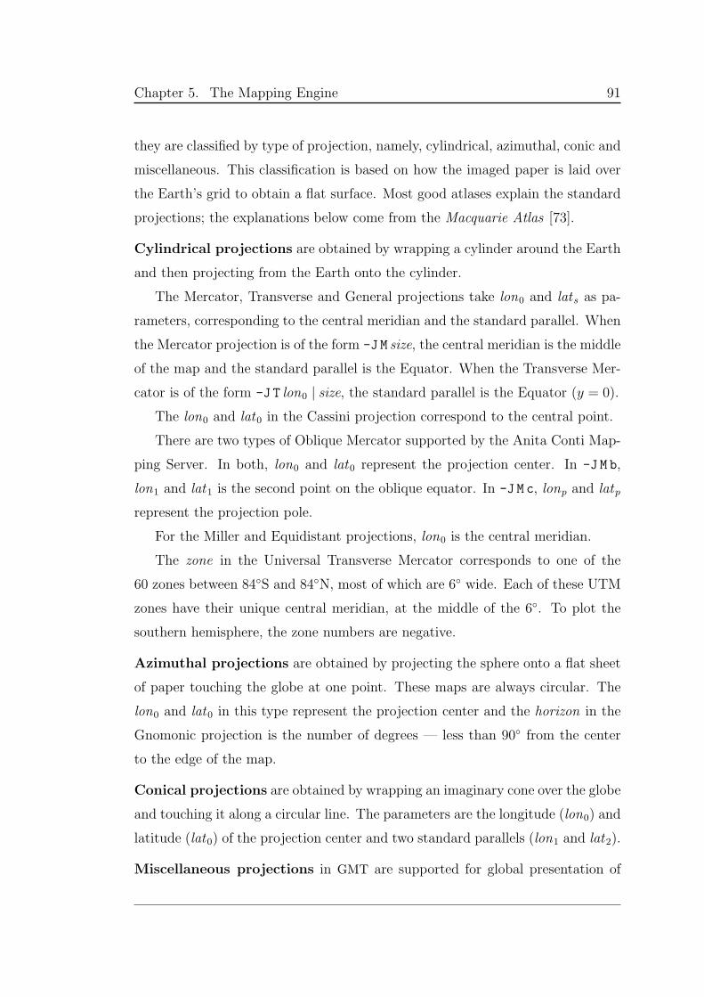
Chapter 5. The Mapping Engine 91
they are classified by type of projection, namely, cylindrical, azimuthal, conic and
miscellaneous. This classification is based on how the imaged paper is laid over
the Earth’s grid to obtain a flat surface. Most good atlases explain the standard
projections; the explanations below come from the Macquarie Atlas [73].
Cylindrical projections are obtained by wrapping a cylinder around the Earth
and then projecting from the Earth onto the cylinder.
The Mercator, Transverse and General projections take lon0 and lats as pa-
rameters, corresponding to the central meridian and the standard parallel. When
the Mercator projection is of the form -J M size, the central meridian is the middle
of the map and the standard parallel is the Equator. When the Transverse Mer-
cator is of the form -J T lon0 | size, the standard parallel is the Equator (y = 0).
The lon0 and lat0 in the Cassini projection correspond to the central point.
There are two types of Oblique Mercator supported by the Anita Conti Map-
ping Server. In both, lon0 and lat0 represent the projection center. In -J M b,
lon1 and lat1 is the second point on the oblique equator. In -J M c, lonp and latp
represent the projection pole.
For the Miller and Equidistant projections, lon0 is the central meridian.
The zone in the Universal Transverse Mercator corresponds to one of the
60 zones between 84S and 84N, most of which are 6 wide. Each of these UTM
zones have their unique central meridian, at the middle of the 6. To plot the
southern hemisphere, the zone numbers are negative.
Azimuthal projections are obtained by projecting the sphere onto a flat sheet
of paper touching the globe at one point. These maps are always circular. The
lon0 and lat0 in this type represent the projection center and the horizon in the
Gnomonic projection is the number of degrees — less than 90 from the center
to the edge of the map.
Conical projections are obtained by wrapping an imaginary cone over the globe
and touching it along a circular line. The parameters are the longitude (lon0) and
latitude (lat0) of the projection center and two standard parallels (lon1 and lat2).
Miscellaneous projections in GMT are supported for global presentation of
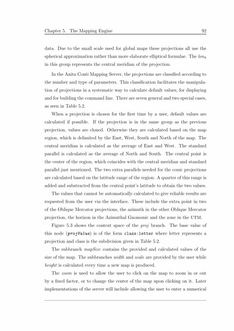
Chapter 5. The Mapping Engine 92
data. Due to the small scale used for global maps these projections all use the
spherical approximation rather than more elaborate elliptical formulae. The lon0
in this group represents the central meridian of the projection.
In the Anita Conti Mapping Server, the projections are classified according to
the number and type of parameters. This classification facilitates the manipula-
tion of projections in a systematic way to calculate default values, for displaying
and for building the command line. There are seven general and two special cases,
as seen in Table 5.2.
When a projection is chosen for the first time by a user, default values are
calculated if possible. If the projection is in the same group as the previous
projection, values are cloned. Otherwise they are calculated based on the map
region, which is delimited by the East, West, South and North of the map. The
central meridian is calculated as the average of East and West. The standard
parallel is calculated as the average of North and South. The central point is
the center of the region, which coincides with the central meridian and standard
parallel just mentioned. The two extra parallels needed for the conic projections
are calculated based on the latitude range of the region: A quarter of this range is
added and substracted from the central point’s latitude to obtain the two values.
The values that cannot be automatically calculated to give reliable results are
requested from the user via the interface. These include the extra point in two
of the Oblique Mercator projections, the azimuth in the other Oblique Mercator
projection, the horizon in the Azimuthal Gnomonic and the zone in the UTM.
Figure 5.3 shows the context space of the proj branch. The base value of
this node (projValue) is of the form class:letter where letter represents a
projection and class is the subdivision given in Table 5.2.
The subbranch mapSize contains the provided and calculated values of the
size of the map. The subbranches width and scale are provided by the user while
height is calculated every time a new map is produced.
The zoom is used to allow the user to click on the map to zoom in or out
by a fixed factor, or to change the center of the map upon clicking on it. Later
implementations of the server will include allowing the user to enter a numerical
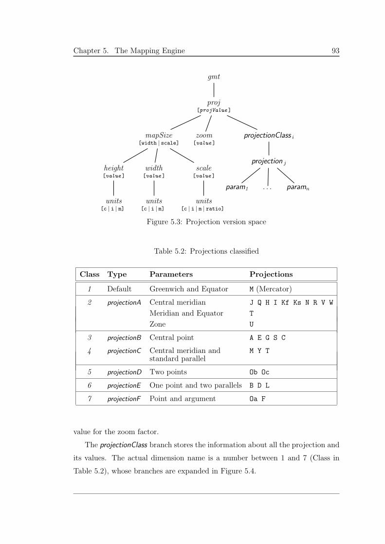
Chapter 5. The Mapping Engine 93
gmt
proj[projValue ]
mapSize[width | scale]
height[value ]
units[c | i | m]
width[value ]
units[c | i | m]
scale[value ]
units[c | i | m | ratio]
zoom[value ]
projectionClass i
projection j
param1 . . . paramn
Figure 5.3: Projection version space
Table 5.2: Projections classified
Class Type Parameters Projections
1 Default Greenwich and Equator M (Mercator)
2 projectionA Central meridian J Q H I Kf Ks N R V W
Meridian and Equator T
Zone U
3 projectionB Central point A E G S C
4 projectionC Central meridian and M Y Tstandard parallel
5 projectionD Two points Ob Oc
6 projectionE One point and two parallels B D L
7 projectionF Point and argument Oa F
value for the zoom factor.
The projectionClass branch stores the information about all the projection and
its values. The actual dimension name is a number between 1 and 7 (Class in
Table 5.2), whose branches are expanded in Figure 5.4.
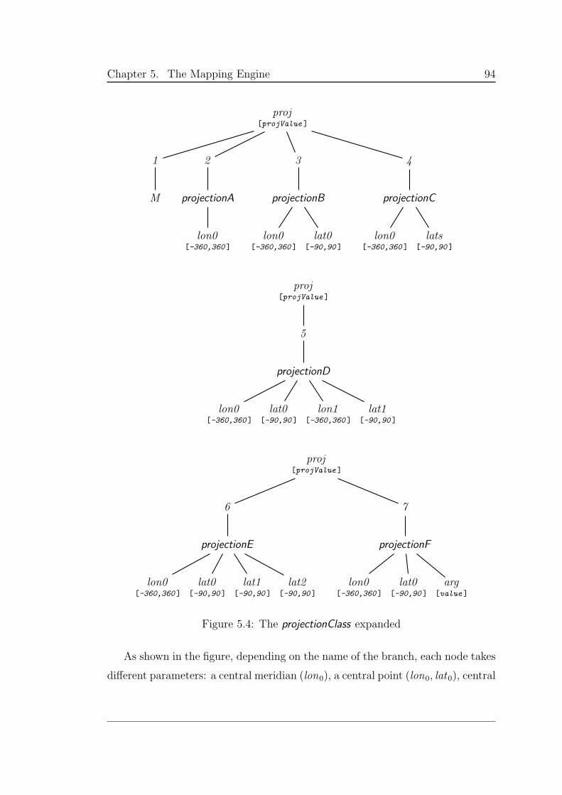
Chapter 5. The Mapping Engine 94
proj[projValue ]
1
M
2
projectionA
lon0[-360,360 ]
3
projectionB
lon0[-360,360 ]
lat0[-90,90 ]
4
projectionC
lon0[-360,360 ]
lats[-90,90 ]
proj[projValue ]
5
projectionD
lon0[-360,360 ]
lat0[-90,90 ]
lon1[-360,360 ]
lat1[-90,90 ]
proj[projValue ]
6
projectionE
lon0[-360,360 ]
lat0[-90,90 ]
lat1[-90,90 ]
lat2[-90,90 ]
7
projectionF
lon0[-360,360 ]
lat0[-90,90 ]
arg[value ]
Figure 5.4: The projectionClass expanded
As shown in the figure, depending on the name of the branch, each node takes
different parameters: a central meridian (lon0), a central point (lon0, lat0), central
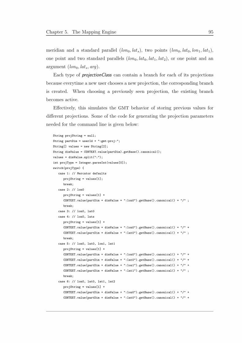
Chapter 5. The Mapping Engine 95
meridian and a standard parallel (lon0, lats), two points (lon0, lat0, lon1, lat1),
one point and two standard parallels (lon0, lat0, lat1, lat2), or one point and an
argument (lon0, lats, arg).
Each type of projectionClass can contain a branch for each of its projections
because everytime a new user chooses a new projection, the corresponding branch
is created. When choosing a previously seen projection, the existing branch
becomes active.
Effectively, this simulates the GMT behavior of storing previous values for
different projections. Some of the code for generating the projection parameters
needed for the command line is given below:
String projString = null;
String partDim = userId + ":gmt:proj:";
String[] values = new String[2];
String dimValue = CONTEXT.value(partDim).getBase().canonical();
values = dimValue.split(":");
int projType = Integer.parseInt(values[0]);
switch(projType)
case 1: // Mercator defaults
projString = values[1];
break;
case 2: // lon0
projString = values[1] +
CONTEXT.value(partDim + dimValue + ":lon0").getBase().canonical() + "/" ;
break;
case 3: // lon0, lat0
case 4: // lon0, lats
projString = values[1] +
CONTEXT.value(partDim + dimValue + ":lon0").getBase().canonical() + "/" +
CONTEXT.value(partDim + dimValue + ":lat0").getBase().canonical() + "/" ;
break;
case 5: // lon0, lat0, lon1, lat1
projString = values[1] +
CONTEXT.value(partDim + dimValue + ":lon0").getBase().canonical() + "/" +
CONTEXT.value(partDim + dimValue + ":lat0").getBase().canonical() + "/" +
CONTEXT.value(partDim + dimValue + ":lon1").getBase().canonical() + "/" +
CONTEXT.value(partDim + dimValue + ":lat1").getBase().canonical() + "/" ;
break;
case 6: // lon0, lat0, lat1, lat2
projString = values[1] +
CONTEXT.value(partDim + dimValue + ":lon0").getBase().canonical() + "/" +
CONTEXT.value(partDim + dimValue + ":lat0").getBase().canonical() + "/" +
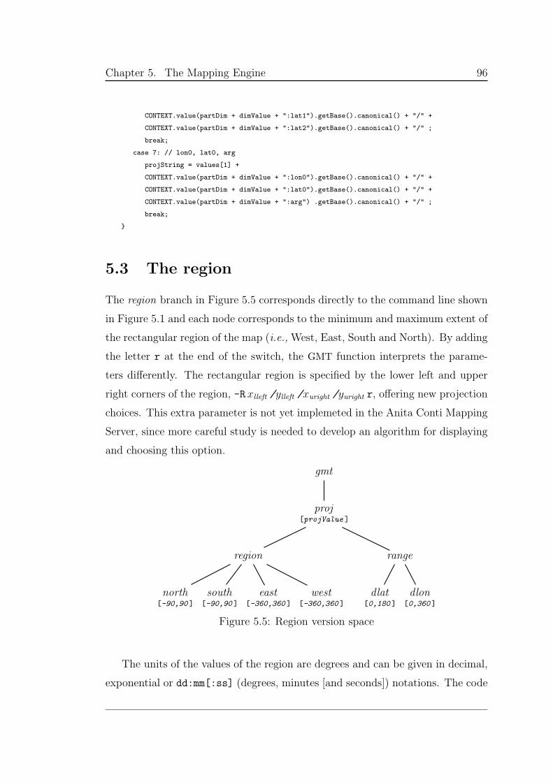
Chapter 5. The Mapping Engine 96
CONTEXT.value(partDim + dimValue + ":lat1").getBase().canonical() + "/" +
CONTEXT.value(partDim + dimValue + ":lat2").getBase().canonical() + "/" ;
break;
case 7: // lon0, lat0, arg
projString = values[1] +
CONTEXT.value(partDim + dimValue + ":lon0").getBase().canonical() + "/" +
CONTEXT.value(partDim + dimValue + ":lat0").getBase().canonical() + "/" +
CONTEXT.value(partDim + dimValue + ":arg") .getBase().canonical() + "/" ;
break;
5.3 The region
The region branch in Figure 5.5 corresponds directly to the command line shown
in Figure 5.1 and each node corresponds to the minimum and maximum extent of
the rectangular region of the map (i.e., West, East, South and North). By adding
the letter r at the end of the switch, the GMT function interprets the parame-
ters differently. The rectangular region is specified by the lower left and upper
right corners of the region, -Rxlleft /ylleft /xuright /yuright r, offering new projection
choices. This extra parameter is not yet implemeted in the Anita Conti Mapping
Server, since more careful study is needed to develop an algorithm for displaying
and choosing this option.
gmt
proj[projValue ]
region
north[-90,90 ]
south[-90,90 ]
east[-360,360 ]
west[-360,360 ]
range
dlat[0,180 ]
dlon[0,360 ]
Figure 5.5: Region version space
The units of the values of the region are degrees and can be given in decimal,
exponential or dd:mm[:ss] (degrees, minutes [and seconds]) notations. The code
Chapter 5. The Mapping Engine 97
used to assemble the region switch is quite simple:
String partDim = userId + ":gmt:proj:region:";
String region = " -R" +
CONTEXT.value(partDim + "west") .getBase().canonical() + "/" +
CONTEXT.value(partDim + "east") .getBase().canonical() + "/" +
CONTEXT.value(partDim + "south").getBase().canonical() + "/" +
CONTEXT.value(partDim + "north").getBase().canonical() ;
The range branch is recalculated every time any of the region parameters
changes. The rectangular region must be kept to a maximum of 360 in longitude
and 180 in latitude. These values are then used for automatic calculation of
projection parameters, to check the minimum tick spacing and for automatic
zooming.
5.4 Map frame and grid
The frame and grid of the map are specified by the switch -B tickinfo. As stated
in the GMT tutorial [2], “This is by far the most complicated option in GMT”,
because the meaning of the string is given in a map context. Understanding them
requires understanding map terminology.
The string tickinfo is of the form:
xinfo [/yinfo ] [ :.“plot title”: ]sideInfo
where xinfo and yinfo are of the form:
[a] interval [ m | c ] [f interval [ m | c ] ] [ g interval [ m | c ] ] labels
labels refer to axis tags:
[:“axis label”:] [:,“unit label”:]
and sideInfo is of the form:
[ W | w ] [ E | e ] [ S | s ] [ N | n ] .
Chapter 5. The Mapping Engine 98
The plottitle, if given, appears centered above the plot.
Each xinfo and yinfo can specify independently a, f and g for annotation,
frame and grid: a stands for adding axis labels, f for adding a segmented border
and g plots lines across the map, all at the interval specified in the command. The
interval can be given in degrees (the default), minutes (including m) or seconds
(including c). If the frame or grid intervals are not set, they are assumed to be
the same as the annotation interval.
If the yinfo is omitted, it is assumed to be the same as that for xinfo.
Labels for each axis can be added by surrounding them with colons. If the
first character in the label is a period, it will be taken as a plot title and not
as an axis label; if it is a comma then the label is appended to each anotation.
To avoid the space between the anotation and the actual unit, start the label
with -. If there is no period or comma, it is an axis label. Double quotes should
be included if the label consists of more than one word.
By default all four map boundaries, West, East, South and North, are plotted
(which is equivalent to apending WESN at the end of the command). This can be
modified by specifying which boundary to plot and how. Lower case draws the
axis and tick marks (according to the interval strings), while upper case will in
addition annotate (add the labels according to the interval of a).
For the purpose of the Anita Conti Mapping Server and as mentioned in §5.2,
all parameters are defined explicitly, as far as it is possible, to avoid discrepancies.
The context contains all the features of the -B switch that have been implemented,
as shown in Figure 5.6.
A base value of off for the frame node gives no frame for the map. In GMT
line command terms, it means supressing the -B option altogether. If it is on, the
rest of the values are analyzed: The x and y subbranches are directly converted
to the equivalent xinfo and yinfo, assuming a default unit of degrees; a title is
added to the map if the base value of the plottitle node is on; and the sideInfo is
added depending on the side subbranch. If all of the sides of the plot are turned
off (n as base value) then the switch is completely eliminated from the command
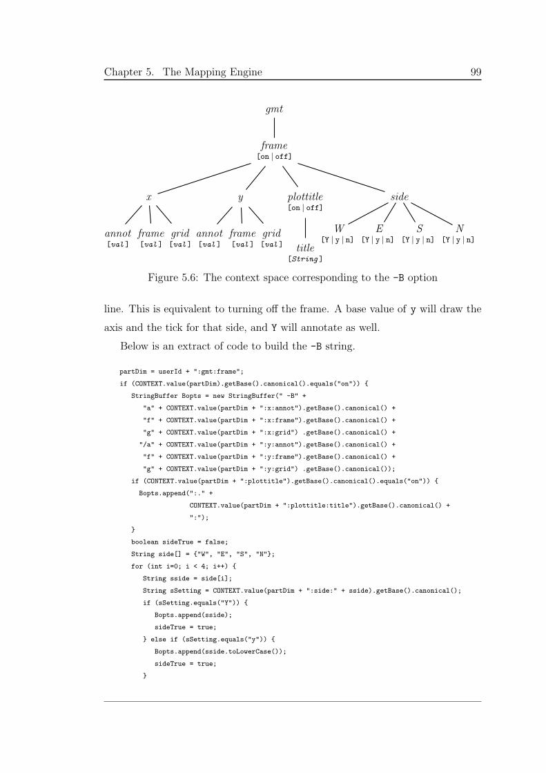
Chapter 5. The Mapping Engine 99
gmt
frame[on | off]
x
annot[val ]
frame[val ]
grid[val ]
y
annot[val ]
frame[val ]
grid[val ]
plottitle[on | off]
title[String ]
side
W[Y | y | n]
E[Y | y | n]
S[Y | y | n]
N[Y | y | n]
Figure 5.6: The context space corresponding to the -B option
line. This is equivalent to turning off the frame. A base value of y will draw the
axis and the tick for that side, and Y will annotate as well.
Below is an extract of code to build the -B string.
partDim = userId + ":gmt:frame";
if (CONTEXT.value(partDim).getBase().canonical().equals("on"))
StringBuffer Bopts = new StringBuffer(" -B" +
"a" + CONTEXT.value(partDim + ":x:annot").getBase().canonical() +
"f" + CONTEXT.value(partDim + ":x:frame").getBase().canonical() +
"g" + CONTEXT.value(partDim + ":x:grid") .getBase().canonical() +
"/a" + CONTEXT.value(partDim + ":y:annot").getBase().canonical() +
"f" + CONTEXT.value(partDim + ":y:frame").getBase().canonical() +
"g" + CONTEXT.value(partDim + ":y:grid") .getBase().canonical());
if (CONTEXT.value(partDim + ":plottitle").getBase().canonical().equals("on"))
Bopts.append(":." +
CONTEXT.value(partDim + ":plottitle:title").getBase().canonical() +
":");
boolean sideTrue = false;
String side[] = "W", "E", "S", "N";
for (int i=0; i < 4; i++)
String sside = side[i];
String sSetting = CONTEXT.value(partDim + ":side:" + sside).getBase().canonical();
if (sSetting.equals("Y"))
Bopts.append(sside);
sideTrue = true;
else if (sSetting.equals("y"))
Bopts.append(sside.toLowerCase());
sideTrue = true;
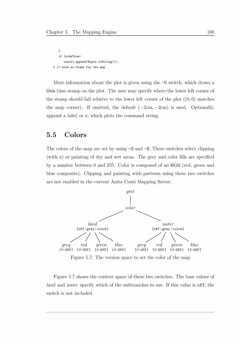
Chapter 5. The Mapping Engine 100
if (sideTrue)
result.append(Bopts.toString());
// else no frame for the map
More information about the plot is given using the -U switch, which draws a
Unix time stamp on the plot. The user may specify where the lower left corner of
the stamp should fall relative to the lower left corner of the plot ((0, 0) matches
the map corner). If omitted, the default (−2cm,−2cm) is used. Optionally,
append a label, or c, which plots the command string.
5.5 Colors
The colors of the map are set by using -G and -S. These switches select clipping
(with c) or painting of dry and wet areas. The grey and color fills are specified
by a number between 0 and 255. Color is composed of an RGB (red, green and
blue composite). Clipping and painting with patterns using these two switches
are not enabled in the current Anita Conti Mapping Server.
gmt
color
land[off | grey | color]
grey[0-255 ]
red[0-255 ]
green[0-255 ]
blue[0-255 ]
water[off | grey | color]
grey[0-255 ]
red[0-255 ]
green[0-255 ]
blue[0-255 ]
Figure 5.7: The version space to set the color of the map
Figure 5.7 shows the context space of these two switches. The base values of
land and water specify which of the subbranches to use. If this value is off, the
switch is not included.
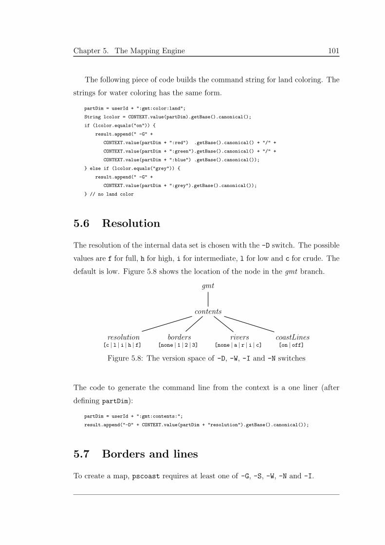
Chapter 5. The Mapping Engine 101
The following piece of code builds the command string for land coloring. The
strings for water coloring has the same form.
partDim = userId + ":gmt:color:land";
String lcolor = CONTEXT.value(partDim).getBase().canonical();
if (lcolor.equals("on"))
result.append(" -G" +
CONTEXT.value(partDim + ":red") .getBase().canonical() + "/" +
CONTEXT.value(partDim + ":green").getBase().canonical() + "/" +
CONTEXT.value(partDim + ":blue") .getBase().canonical());
else if (lcolor.equals("grey"))
result.append(" -G" +
CONTEXT.value(partDim + ":grey").getBase().canonical());
// no land color
5.6 Resolution
The resolution of the internal data set is chosen with the -D switch. The possible
values are f for full, h for high, i for intermediate, l for low and c for crude. The
default is low. Figure 5.8 shows the location of the node in the gmt branch.
gmt
contents
resolution[c | l | i | h | f]
borders[none | 1 | 2 | 3]
rivers[none | a | r | i | c]
coastLines[on | off]
Figure 5.8: The version space of -D, -W, -I and -N switches
The code to generate the command line from the context is a one liner (after
defining partDim):
partDim = userId + ":gmt:contents:";
result.append("-D" + CONTEXT.value(partDim + "resolution").getBase().canonical());
5.7 Borders and lines
To create a map, pscoast requires at least one of -G, -S, -W, -N and -I.
Chapter 5. The Mapping Engine 102
Coastlines are set using -W and the only pen attribute that we are enabling is
width, which (for now) is fixed and set internally, as seen in the code. The only
option available to the user is to turn this switch on or off, as seen in Figure 5.8.
if (CONTEXT.value(partDim + "coastLines").getBase().canonical().equals("on"))
result.append(" -W2");
Political boundaries are drawn using -N and represented in Figure 5.8 by the
branch borders . The value none supresses this switch from the command line.
There are national boundaries, state boundaries within the Americas and marine
boundaries. In the context space, 1 includes national boundaries, 2 adds state
boundaries, where available, and 3 includes marine boundaries. The code with
the default pen widths is seen below. That the numbers are cumulative is a design
option that can be modified should it be needed.
int border = Integer.parseInt(CONTEXT.value(partDim + "borders").getBase().canonical());
switch(border)
case 3: // include all
result.append(" -N3/0.25");
case 2: // include national and state
result.append(" -N2/0.5");
case 1: // include only national
result.append(" -N1/1");
break;
Rivers are plotted using the -I switch and the base values in Figuire 5.8
correspond to the following: a plots all rivers and canals, r plots all permanent
rivers, i plots all intermittent rivers and c plots all canals.
String river = CONTEXT.value(partDim + "rivers").getBase().canonical();
result.append(" -I" + river + "/0.25");
5.8 Layers and layout
The rest of the options included in the command line concern general map layout.
A plot usually has an x-axis increasing from left to right and a y-axis increasing
from bottom to top. If the paper is turned so that the long dimension of the paper
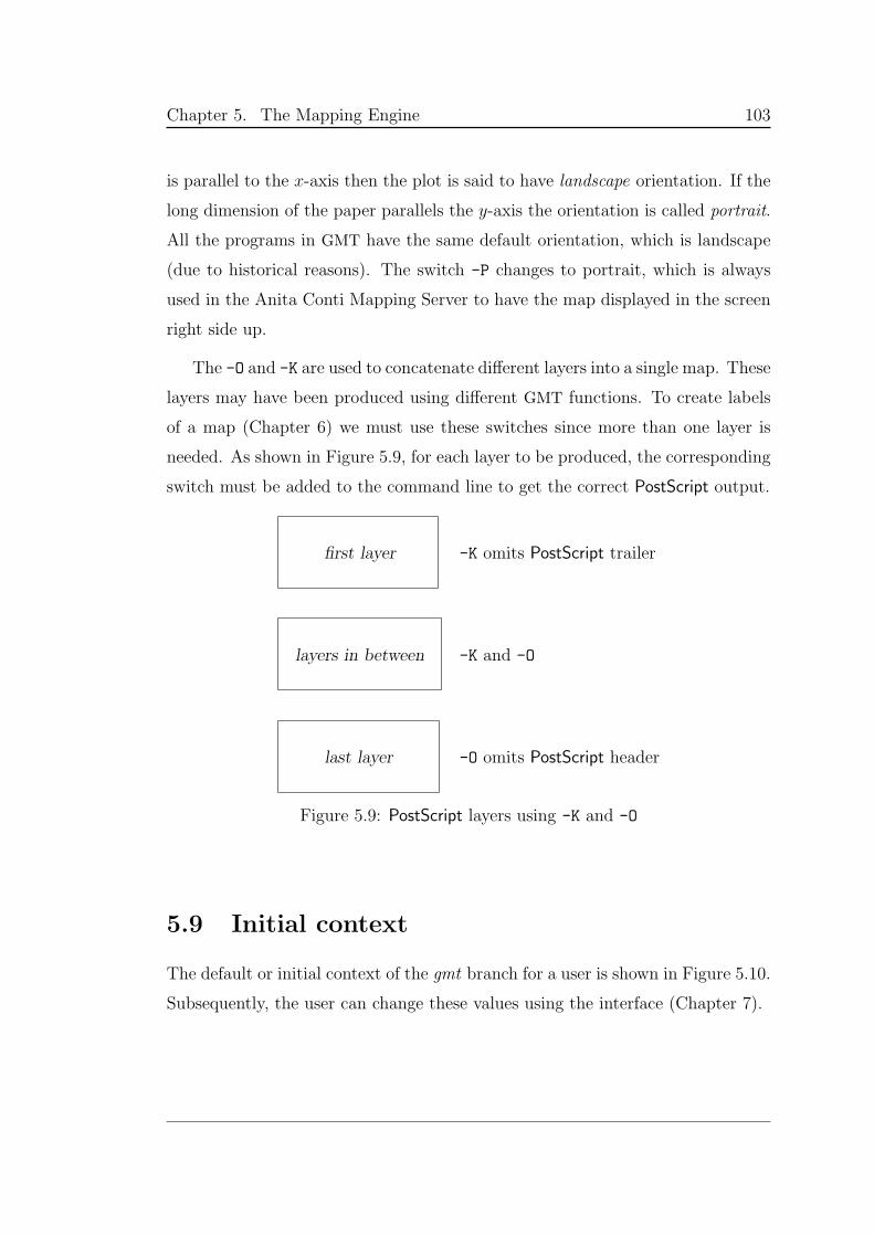
Chapter 5. The Mapping Engine 103
is parallel to the x-axis then the plot is said to have landscape orientation. If the
long dimension of the paper parallels the y-axis the orientation is called portrait.
All the programs in GMT have the same default orientation, which is landscape
(due to historical reasons). The switch -P changes to portrait, which is always
used in the Anita Conti Mapping Server to have the map displayed in the screen
right side up.
The -O and -K are used to concatenate different layers into a single map. These
layers may have been produced using different GMT functions. To create labels
of a map (Chapter 6) we must use these switches since more than one layer is
needed. As shown in Figure 5.9, for each layer to be produced, the corresponding
switch must be added to the command line to get the correct PostScript output.
first layer -K omits PostScript trailer
layers in between -K and -O
last layer -O omits PostScript header
Figure 5.9: PostScript layers using -K and -O
5.9 Initial context
The default or initial context of the gmt branch for a user is shown in Figure 5.10.
Subsequently, the user can change these values using the interface (Chapter 7).
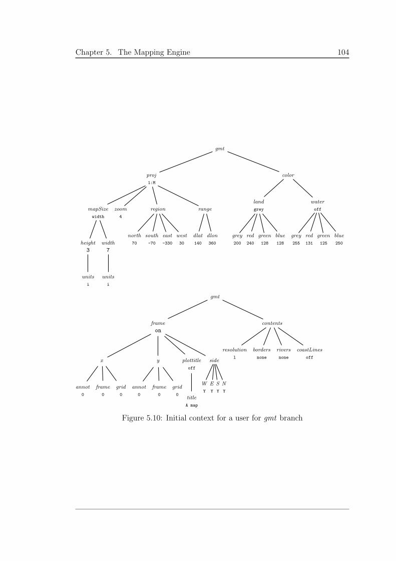
Chapter 5. The Mapping Engine 104
gmt
proj
1:M
mapSize
width
height
3
units
i
width
7
units
i
zoom
4
region
north
70
south
-70
east
-330
west
30
range
dlat
140
dlon
360
color
land
grey
grey
200
red
240
green
128
blue
128
water
off
grey
255
red
131
green
125
blue
250
gmt
frame
on
x
annot
0
frame
0
grid
0
y
annot
0
frame
0
grid
0
plottitle
off
title
A map
side
W
Y
E
Y
S
Y
N
Y
contents
resolution
l
borders
none
rivers
none
coastLines
off
Figure 5.10: Initial context for a user for gmt branch
Chapter 6
Multilingual text and Maps
Or the lack of them.
As with everything else in the maps produced by the Anita Conti Mapping Server,
the labels generated by the server are also parameterized by the context. In this
chapter, we examine the difficulties in storing and printing multilingual labels for
geographical place names.
When preparing the labels for a map, there are three problems that must be
solved. First, the set of labels to be placed on the map must be chosen. Second,
these labels must be typeset according to the specifications of the map. Finally,
these typeset labels must be placed on the map, possibly with mechanisms to
avoid placing labels one on top of another or clashing with other map objects.
Even if a simplistic label placement algorithm — the problem is NP-hard —
is used, the management of multilingual labels for geographical place names is far
more complex than it might first appear. Initially the problem was understood as
simply attaching a text string to every (location, language) pair, and then calling
a typesetting engine, such as Ω, on the needed labels. This is in fact the solution
that is implemented for the current Anita Conti Mapping Server.
However, if the mapping server is to become truly multi-purpose, so that it
can incorporate historical mapping, and deal with subtle changes in language
and script, then the model for text must itself become multidimensional, as has
been proposed by the authors of Ω [74, 75] and of LATEX [76, 77]. Influenced by
105
Chapter 6. Multilingual text and Maps 106
this work, we have designed the intensional relational database, generalizing the
RDBMS so that relations themselves become context-dependent.
This chapter is therefore organized into two parts, the actual and the ideal.
We begin with the mechanisms provided by GMT for placing labels in maps (§6.1),
and explain how the overall Anita Conti Mapping Server architecture generalizes
this approach, calling the Ω Typesetting System for multilingual texts. We then
explain the structure of the place name database (§6.2), how queries to this
database are generated when maps are created (§6.3), and how the collected
labels are placed and typeset (§6.4).
The second part begins with an in-depth discussion (§6.5) of the problems
posed by multilingual place-names for historical maps, and outlines how the gen-
eralized use of context once again offers a solution. The intensional database pro-
posal follows, with an intensional relational algebra and an Intensional SQL (§6.6).
We conclude with a discussion of future development.
6.1 Adding labels to maps
As mentioned in §5.8, GMT produces its maps in PostScript layers [78, 79], one
layer per function. These layers do not necessarily coincide with map layers, since
one function output may contain more than one map layer.
An Encapsulated PostScript file has a header and a trailer surrounding the
contents. To allow for layers, a GMT user must tell each function which layer it
is producing: the first layer, which includes only a header; the last layer, which
includes only a trailer; or layers in between, which include neither. If the function
is producing the full map, the layer contains both header and trailer. Figure 5.9
(p.103) explains how to use the GMT switches -K and -O to produce each case.
GMT offers a function called pstext to plot text strings of variable size, font
type, and orientation. There are 38 freely available fonts (in GMT version 3.4.2),
including the standard PostScript fonts, special switches for European accented
characters and Greek symbols.
The argument to pstext is a text file containing a number of records of the
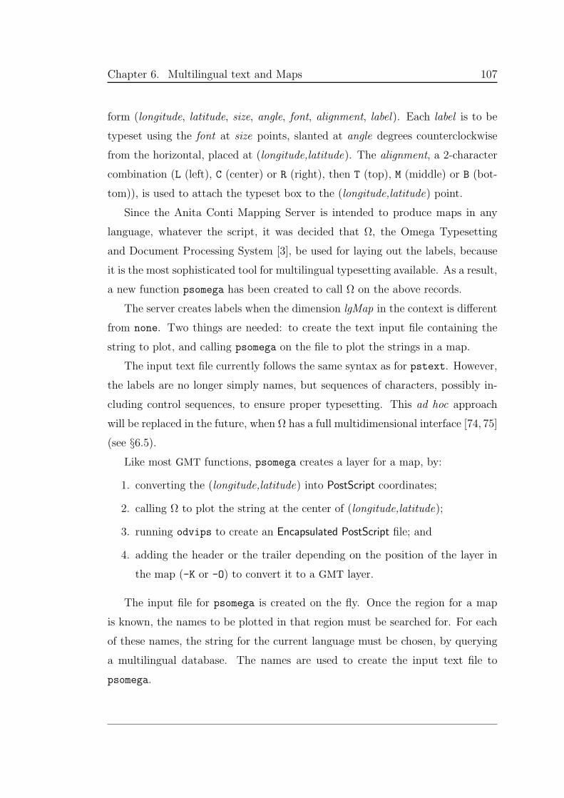
Chapter 6. Multilingual text and Maps 107
form (longitude, latitude, size, angle, font, alignment, label). Each label is to be
typeset using the font at size points, slanted at angle degrees counterclockwise
from the horizontal, placed at (longitude,latitude). The alignment, a 2-character
combination (L (left), C (center) or R (right), then T (top), M (middle) or B (bot-
tom)), is used to attach the typeset box to the (longitude,latitude) point.
Since the Anita Conti Mapping Server is intended to produce maps in any
language, whatever the script, it was decided that Ω, the Omega Typesetting
and Document Processing System [3], be used for laying out the labels, because
it is the most sophisticated tool for multilingual typesetting available. As a result,
a new function psomega has been created to call Ω on the above records.
The server creates labels when the dimension lgMap in the context is different
from none. Two things are needed: to create the text input file containing the
string to plot, and calling psomega on the file to plot the strings in a map.
The input text file currently follows the same syntax as for pstext. However,
the labels are no longer simply names, but sequences of characters, possibly in-
cluding control sequences, to ensure proper typesetting. This ad hoc approach
will be replaced in the future, when Ω has a full multidimensional interface [74, 75]
(see §6.5).
Like most GMT functions, psomega creates a layer for a map, by:
1. converting the (longitude,latitude) into PostScript coordinates;
2. calling Ω to plot the string at the center of (longitude,latitude);
3. running odvips to create an Encapsulated PostScript file; and
4. adding the header or the trailer depending on the position of the layer in
the map (-K or -O) to convert it to a GMT layer.
The input file for psomega is created on the fly. Once the region for a map
is known, the names to be plotted in that region must be searched for. For each
of these names, the string for the current language must be chosen, by querying
a multilingual database. The names are used to create the input text file to
psomega.
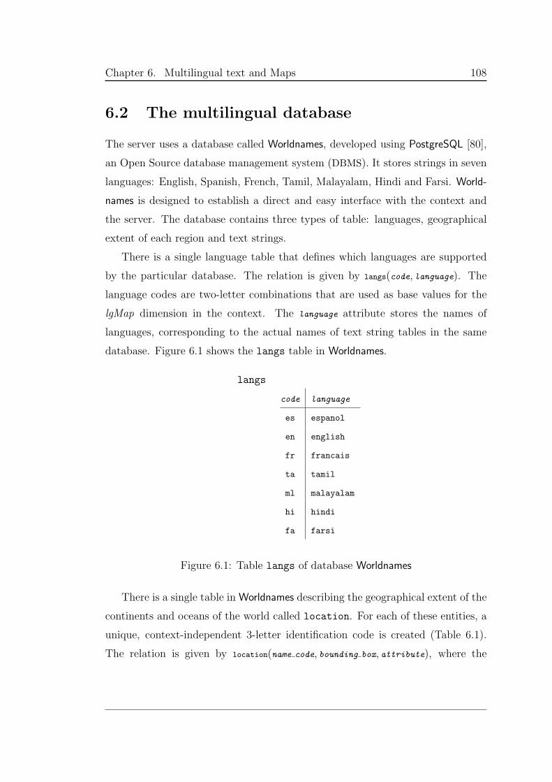
Chapter 6. Multilingual text and Maps 108
6.2 The multilingual database
The server uses a database called Worldnames, developed using PostgreSQL [80],
an Open Source database management system (DBMS). It stores strings in seven
languages: English, Spanish, French, Tamil, Malayalam, Hindi and Farsi. World-
names is designed to establish a direct and easy interface with the context and
the server. The database contains three types of table: languages, geographical
extent of each region and text strings.
There is a single language table that defines which languages are supported
by the particular database. The relation is given by langs(code, language). The
language codes are two-letter combinations that are used as base values for the
lgMap dimension in the context. The language attribute stores the names of
languages, corresponding to the actual names of text string tables in the same
database. Figure 6.1 shows the langs table in Worldnames.
langs
code language
es espanol
en english
fr francais
ta tamil
ml malayalam
hi hindi
fa farsi
Figure 6.1: Table langs of database Worldnames
There is a single table in Worldnames describing the geographical extent of the
continents and oceans of the world called location. For each of these entities, a
unique, context-independent 3-letter identification code is created (Table 6.1).
The relation is given by location(name code, bounding box, attribute), where the
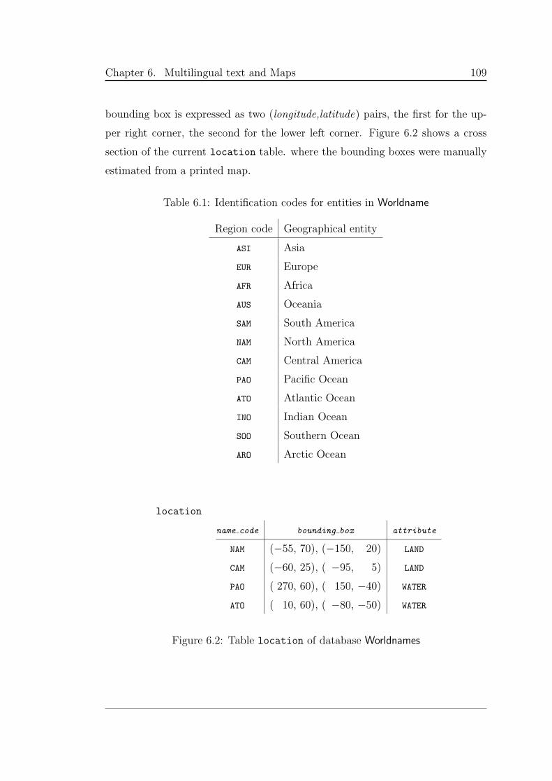
Chapter 6. Multilingual text and Maps 109
bounding box is expressed as two (longitude,latitude) pairs, the first for the up-
per right corner, the second for the lower left corner. Figure 6.2 shows a cross
section of the current location table. where the bounding boxes were manually
estimated from a printed map.
Table 6.1: Identification codes for entities in Worldname
Region code Geographical entity
ASI Asia
EUR Europe
AFR Africa
AUS Oceania
SAM South America
NAM North America
CAM Central America
PAO Pacific Ocean
ATO Atlantic Ocean
INO Indian Ocean
SOO Southern Ocean
ARO Arctic Ocean
location
name code bounding box attribute
NAM (−55, 70), (−150, 20) LAND
CAM (−60, 25), ( −95, 5) LAND
PAO ( 270, 60), ( 150, −40) WATER
ATO ( 10, 60), ( −80, −50) WATER
Figure 6.2: Table location of database Worldnames
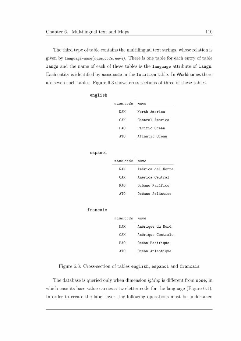
Chapter 6. Multilingual text and Maps 110
The third type of table contains the multilingual text strings, whose relation is
given by language-name(name code, name). There is one table for each entry of table
langs and the name of each of these tables is the language attribute of langs.
Each entity is identified by name code in the location table. In Worldnames there
are seven such tables. Figure 6.3 shows cross sections of three of these tables.
english
name code name
NAM North America
CAM Central America
PAO Pacific Ocean
ATO Atlantic Ocean
espanol
name code name
NAM America del Norte
CAM America Central
PAO Oceano Pacıfico
ATO Oceano Atlantico
francais
name code name
NAM Amerique du Nord
CAM Amerique Centrale
PAO Ocean Pacifique
ATO Ocean Atlantique
Figure 6.3: Cross-section of tables english, espanol and francais
The database is queried only when dimension lgMap is different from none, in
which case its base value carries a two-letter code for the language (Figure 6.1).
In order to create the label layer, the following operations must be undertaken
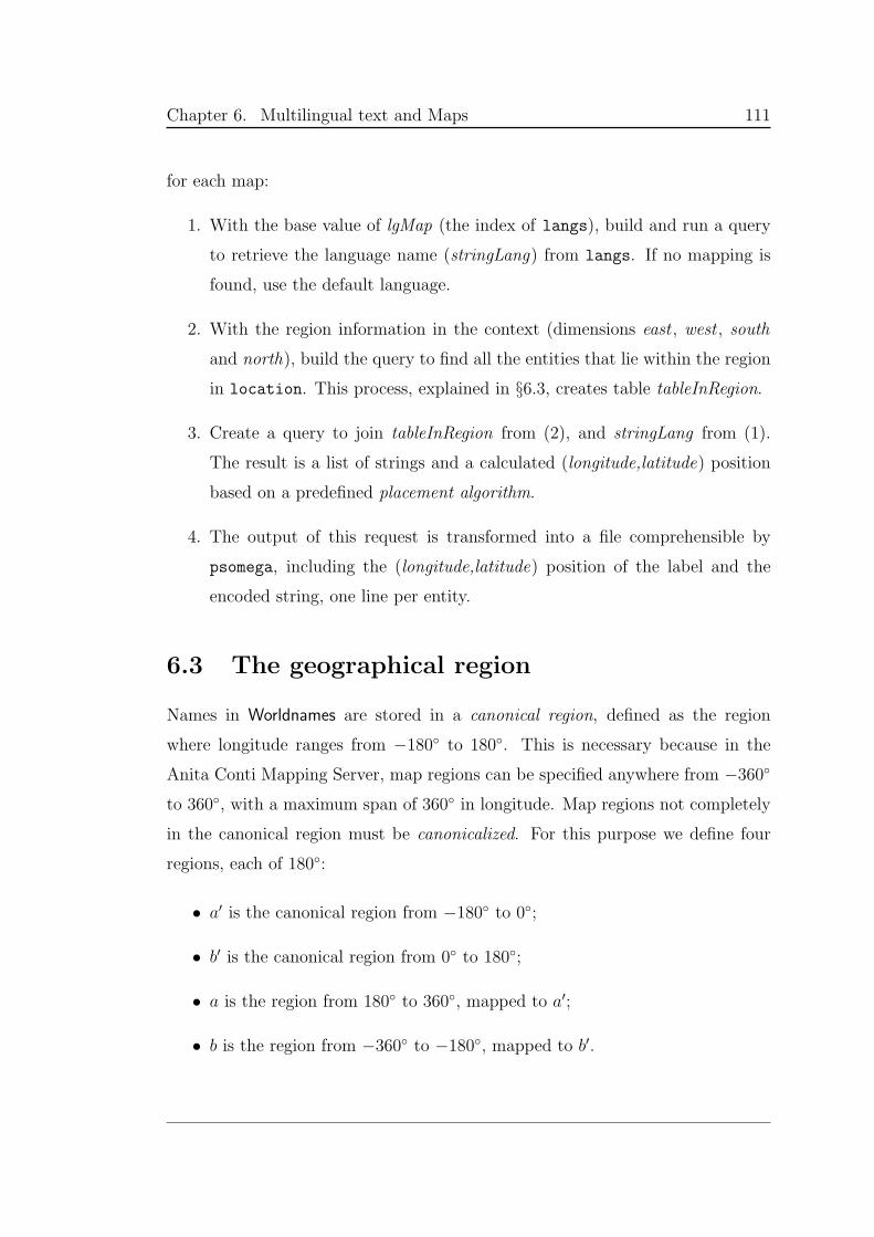
Chapter 6. Multilingual text and Maps 111
for each map:
1. With the base value of lgMap (the index of langs), build and run a query
to retrieve the language name (stringLang) from langs. If no mapping is
found, use the default language.
2. With the region information in the context (dimensions east , west , south
and north), build the query to find all the entities that lie within the region
in location. This process, explained in §6.3, creates table tableInRegion.
3. Create a query to join tableInRegion from (2), and stringLang from (1).
The result is a list of strings and a calculated (longitude,latitude) position
based on a predefined placement algorithm.
4. The output of this request is transformed into a file comprehensible by
psomega, including the (longitude,latitude) position of the label and the
encoded string, one line per entity.
6.3 The geographical region
Names in Worldnames are stored in a canonical region, defined as the region
where longitude ranges from −180 to 180. This is necessary because in the
Anita Conti Mapping Server, map regions can be specified anywhere from −360
to 360, with a maximum span of 360 in longitude. Map regions not completely
in the canonical region must be canonicalized. For this purpose we define four
regions, each of 180:
• a′ is the canonical region from −180 to 0;
• b′ is the canonical region from 0 to 180;
• a is the region from 180 to 360, mapped to a′;
• b is the region from −360 to −180, mapped to b′.

Chapter 6. Multilingual text and Maps 112
Figure 6.4 shows all the possible contiguous longitude spans of less than 360.
The numeric tags on the spans are used in Figures 6.5–6.7, which show how the
spans are canonicalized.
-360 -180 0 180︸ ︸︸ ︸︸ ︸︸ ︸
360
b b′a′ a
7
8
9
1
2
4
3
5
6
Figure 6.4: Possible map region span (in longitude)
The transformations presented in Figures 6.5–6.7 explain the problem to fix.
Coding up a solution, however, requires special care to properly cover all of the
possibilities. For any given region there are three possible scenarios:
1. The map range corresponds to the canonical region (regions a′ and b′ in
Figure 6.4), in which case no transformation is needed. This corresponds
to the three map ranges 1, 2, and 3 shown in Figure 6.5.
2. The map range is completely outside the canonical region (it is in regions a
or b) in which case, the range is translated as one section. This scenario
corresponds to map ranges 6 (Figure 6.6) and 7 (Figure 6.7). The figures
also show the ranges after transformation.
3. The range overlaps with the canonical region, so that only part of the range
is translated. This part corresponds to the range lying in regions a or b.
This scenario corresponds to 4 and 5 in Figure 6.6, and 8 and 9 in Figure 6.7.
These scenarios correspond to a natural division of the cases in Figure 6.4.
For the implementation the cases are labelled as: needing no transformation
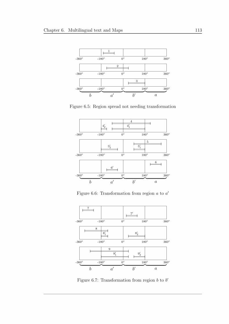
Chapter 6. Multilingual text and Maps 113
-360 -180 0 180 360
1
-360 -180 0 180 360
2
-360 -180 0 180 360︸ ︸︸ ︸︸ ︸︸ ︸
b b′a′ a
3
Figure 6.5: Region spread not needing transformation
-360 -180 0 180 360
4
4′1
4′2
-360 -180 0 180 360
5
5′1
5′2
-360 -180 0 180 360︸ ︸︸ ︸︸ ︸︸ ︸
b b′a′ a
6
6′
Figure 6.6: Transformation from region a to a′
-360 -180 0 180 360
7
7′
-360 -180 0 180 360
8
8′1
8′2
-360 -180 0 180 360︸ ︸︸ ︸︸ ︸︸ ︸
b b′a′ a
9
9′1
9′2
Figure 6.7: Transformation from region b to b′
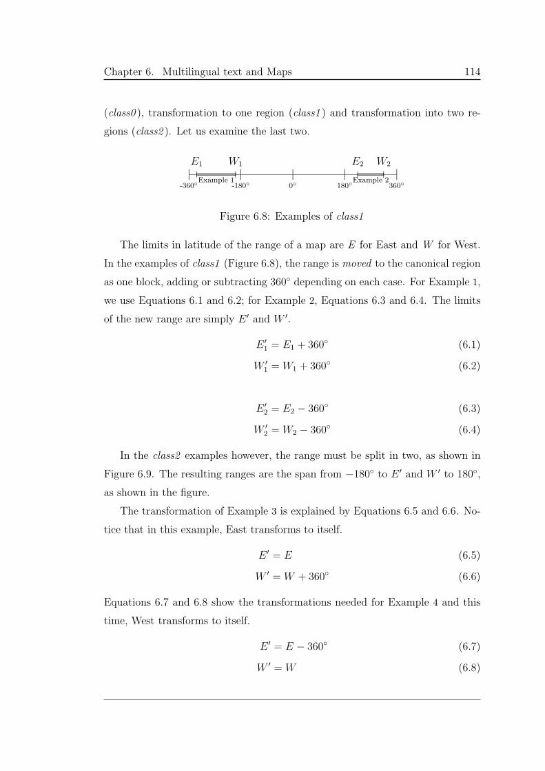
Chapter 6. Multilingual text and Maps 114
(class0 ), transformation to one region (class1 ) and transformation into two re-
gions (class2 ). Let us examine the last two.
|-360
|-180
|0
|180
|360
E1 W1 E2 W2
Example 2
Example 1
Figure 6.8: Examples of class1
The limits in latitude of the range of a map are E for East and W for West.
In the examples of class1 (Figure 6.8), the range is moved to the canonical region
as one block, adding or subtracting 360 depending on each case. For Example 1,
we use Equations 6.1 and 6.2; for Example 2, Equations 6.3 and 6.4. The limits
of the new range are simply E ′ and W ′.
E ′
1 = E1 + 360 (6.1)
W ′
1 = W1 + 360 (6.2)
E ′
2 = E2 − 360 (6.3)
W ′
2 = W2 − 360 (6.4)
In the class2 examples however, the range must be split in two, as shown in
Figure 6.9. The resulting ranges are the span from −180 to E ′ and W ′ to 180,
as shown in the figure.
The transformation of Example 3 is explained by Equations 6.5 and 6.6. No-
tice that in this example, East transforms to itself.
E ′ = E (6.5)
W ′ = W + 360 (6.6)
Equations 6.7 and 6.8 show the transformations needed for Example 4 and this
time, West transforms to itself.
E ′ = E − 360 (6.7)
W ′ = W (6.8)
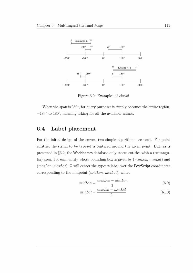
Chapter 6. Multilingual text and Maps 115
|-360
|-180
|0
|180
|360
E W
W’-180 E’ 180
Example 3
|-360
|-180
|0
|180
|360
E W
W’ -180 180E’
Example 4
Figure 6.9: Examples of class2
When the span is 360, for query purposes it simply becomes the entire region,
−180 to 180, meaning asking for all the available names.
6.4 Label placement
For the initial design of the server, two simple algorithms are used. For point
entities, the string to be typeset is centered around the given point. But, as is
presented in §6.2, the Worldnames database only stores entities with a (rectangu-
lar) area. For each entity whose bounding box is given by (minLon, minLat) and
(maxLon, maxLat), Ω will center the typeset label over the PostScript coordinates
corresponding to the midpoint (midLon, midLat), where
midLon =maxLon−minLon
2(6.9)
midLat =maxLat−minLat
2(6.10)
Chapter 6. Multilingual text and Maps 116
6.5 Multiparametric data
So far we have assumed that there is a direct and unique correspondence between
language, location and text string, assumptions spelled out in Worldnames. But
even people that speak the same language express themselves differently. This
difference is even more obvious in the written language. When it is typeset,
language has its own context [75].
At the language presentation level, for Japanese the typesetter needs to know
the writing direction (horizontal or vertical), the script to be used (kanji and
kana, or romaji), and must take into account the time period (the use of both
katakana and romaji has significantly evolved in the last century, as has the look
of Chinese characters). If an old German map is to be reproduced, it should
be typeset using the broken scripts rather than the Latin script. Similarly, an
Ottoman map should be reproduced using the Arabic script rather than the Latin
script.
But context does not just play a role in presentation. Geographical place
names vary according to a large array of different parameters. Places in the
Earth may have more than one official name, a name that changes depending
on the political regime, or a commonly used name. All this without taking into
account changes in boundaries and extent, nor the political inclinations of the
map maker when mapping disputed territory.
Translations of many places in languages of the same script will remain the
same, with some exceptions. For example, the city name Paris (capital of France)
is correct for most languages that use the Latin script. However for Italian, it
becomes Parigi. The English name is the same as the French name, but the official
name is the city of Paris or better yet La Ville de Paris. The city name Vienna
(capital of Austria) is correct for English and Italian, but it becomes Wien in
German (the official language, hence the official name), Vienne in French, Viena
in Spanish.
The common names used by locals are sometimes reminiscent of older names
and do not always correspond to official names. The recently renamed city of
Chapter 6. Multilingual text and Maps 117
Thiruvananthapuram in the state of Kerala (India) was long known as Trivan-
drum, and it is still under that name that most non-Indians know it, and many
Indians as well. The same applies to the Tamil Nadu city of Chennai, long known
as Madras. In the local languages, these cities have always been Thiruvanantha-
puram in Malayalam and Chennai in Tamil, respectively.
On top of language and political distinction of names, one must also deal
with the fact that both names and translations have historical validity. For
example, Paris, in Roman times, was known as Lutetia. As for Vilnius (capital of
Lithuania), it is known as Vilnius in Lithuanian, Wilna in German, and Wilno
in Polish. Each of these names has been the official name at some point in time.
The English translation now corresponds to the current official name, but when
Vilnius was part of Prussia, the English translation was a modified version of the
German name, Vilna. Hence the English translation has time validity.
In other cases, the official name changes completely with language, and the
official language depends on the current political situation. Saint Petersburg,
Russia’s second city, is an example of an entity that has changed its name rad-
ically on several occasions. During the twentieth century its name passed from
Sankt Petersburg (in Cyrillic script) to Petrograd during WWI to Leningrad (in
1923) back to Sankt Peterburg (in 1991). Presently, its English translation is
Saint Petersburg. If we were to enquire about these names in Spanish in the cor-
responding time frame, the strings just mentioned would become San Petesburgo,
Petrogrado, Leningrado and San Petesburgo.
For any given map, given all the above variance, one must decide exactly what
kind of names are needed, along with a detailed language description. A map
can show the official name, the common name, the used name (a short version
of the official name and not necessarily the common name), and translations of
each, or a combination of these. Usually, the official name varies with time and
political regime; the translation of the name depends on the time, the language,
the regime and the official name; the common name and the used name depend
on time and regime (official language). And for each of them, there might be
Chapter 6. Multilingual text and Maps 118
exceptions to the rule. The problems get worse in countries with several official
languages, where any entity may have several official names.
In addition, we have assumed that the cities mentioned have remained undi-
vided through time. So how should one deal with entities that have not always
been united, such as the city of Berlin? For such entities, the identification codes
do vary with context, notwithstanding the suppositions made in §6.2.
Inevitably then, geographical names cannot be plain strings; they must be
viewed as mappings from a multidimensional context to strings. It is clear that
the name of a place depends on many parameters, and only by using the values
of these parameters can we find the correct name.
Present database paradigms do not offer an efficient and clean way to store
these geographical names ready for typesetting. Below, we present our proposal
for an intensional query language that would allow versioned databases, in the
intensional sense, all the way to the core.
6.6 Intensional SQL
The intensional relational database is the natural intensional generalization of
the relational database. As was shown in Chapter 3, the extensional object, here
the traditional relational table, is generalized into an intension, a mapping from
contexts to extensions.
We begin the discussion with a presentation of the intensional relational alge-
bra, which is simply the relational algebra with a single new operator, for context
change. Below is the syntax for expressions (iR) in this algebra, where iR stands
for intensional relation and Cop is a context operator.
Chapter 6. Multilingual text and Maps 119
iR ::= iR named relation
| iR〈Cop〉 context change
| πS iR projection
| ρS iR renaming
| σcond iR selection
| iR× iR′ Cartesian product
| iR ∪ iR′ union
| iR ∩ iR′ intersection
| iR ⊲⊳ iR′ relational join
| iR÷ iR′ quotient
Since an intensional relation iR is an intension, a mapping from contexts to
ordinary relations, we write iR(C) for the meaning of iR in a specific context C.
The semantics of an expression in the intensional relational algebra is straight-
forward. The term [[iR]]C gives the meaning of expression iR in context C. In the
semantics given below, the context only plays an active role in the first two lines.
The other lines state that each of the standard relational operators is applied
pointwise to its arguments, regardless of the context.
[[iR]]C = iR(C)
[[iR〈Cop〉]]C = [[iR]](C Cop)
[[πS iR]]C = πS [[iR]]C
[[ρS iR]]C = ρS [[iR]]C
[[σcond iR]]C = σcond [[iR]]C
[[iR× iR′]]C = [[iR]]C × [[iR′]]C
[[iR ∪ iR′]]C = [[iR]]C ∪ [[iR′]]C
[[iR ∩ iR′]]C = [[iR]]C ∩ [[iR′]]C
[[iR ⊲⊳ iR′]]C = [[iR]]C ⊲⊳ [[iR′]]C
[[iR÷ iR′]]C = [[iR]]C ÷ [[iR′]]C
Chapter 6. Multilingual text and Maps 120
The intensional relation is derived directly from the ordinary, extensional
relation. The same holds true for the intensional relational database. We first
present a simplistic view of a relational database, ignoring concepts such as first,
second and third normal forms of a database:
DB = Id → (Table ∪KTable)
Table = Tuple∗
KTable = Key → Tuple
Tuple = Id → Value
A relational database DB consists of a set of named tables. An ordinary table
Table is a set of tuples, while a table with a key KTable can be considered to be
a mapping from keys to tuples. And a tuple Tuple can be viewed as mappings
from named attributes to values. In the intensional relational database, tables,
tuples and values can all be versioned. Hence the context intervenes at each level:
iDB = Id → Context → (iTable ∪ iKTable)
iTable = (Context → iTuple)∗
iKTable = Key → Context → iTuple
iTuple = Id → Context → Value
Having presented the iDB, we can move on to iSQL. The operations use a
shorthand notation corresponding to the database entities above, and they are:
iτ = τ〈C〉∗
it = (iv1, . . . , ivm)〈C〉∗
iv = v〈C〉∗
where iτ stands for intensional table, it for intensional tuple and iv for intensional
value. The v〈C〉∗ means that an extensional value v is valid for a number of
contexts 〈C〉∗. This syntax is reminiscent of that used in ISE:
$<lang:en><lang:es><lang:fr>cityofparis = Paris.
Chapter 6. Multilingual text and Maps 121
Below, we present each SQL operation with it intensional counterpart. Each
shows the level of indirection of the different entities:
INSERT INTO τ(c1, . . . , cm) VALUES (v1, . . . , vm)
iINSERT INTO iτ(c1, . . . , cm) VALUES it∗
SELECT c1, . . . , cm FROM τ1, . . . , τn WHERE cond
iSELECT c1, . . . , cm FROM iτ1, . . . , iτn WHERE cond UNDER icond
UPDATE τ SET c1 = v1, . . . , cm = vm WHERE cond
iUPDATE iτ SET c1 = iv1, . . . , cm = ivm WHERE cond UNDER icond
DELETE FROM τ WHERE cond
iDELETE FROM iτ WHERE cond UNDER icond
where c stands for column and icond consists of context modifiers.
The relational schemas (i.e., the number and names of colums c1, . . . , cm) are
not versioned in this iSQL scenario. This avoids a lot of data typing problems
which require strict study for formalization.
The context modifiers in icond are context operators Cop, that can modify
any of iτ , it or iv.
Implementation of iSQL as described above would vary greatly, depending
on the host database system, or whether the database were implemented from
scratch. Changes are required from the level of the SQL parser, down to the level
of the database engine itself. Even with only versioning of rows and values, table
structure would have to be altered significantly to provide a usably efficient im-
plementation. A naive alternative might be to maintain special (parallel) version
tables for each table with versionable rows — this would require expensive joins
and post-processing for intensional operations at a layer above SQL. An efficient
implementation would combine well known intensional algorithms for best fits
and refinement with traditional SQL operations.
Versioning of entire tables implies the versioning of schemas; for an iSQL
statement to work, the set of all schemas on which it might potentially operate
must be consistent with the table and column identifiers used in the statement.
Chapter 6. Multilingual text and Maps 122
Whatever the path, significant implementation would be required for the
whole structure to work. But if done, it would naturally solve so many prob-
lems in multiparameteric data storage.
6.7 Building a multiversion database
6.7.1 Versioned names
The geographic place name is a vast, multidimensional space hard to store ef-
ficiently. Being able to make a distinction between the official names, common
names and the translations provides different options for map display. A map
of Germany might appear differently, depending on the user: An Italian native
speaker who is learning German geography may want all the names in Italian,
while an Italian tourist who has already done his German geography class would
want to know about the official names (to consult local guides) and the common
names (how the locals refer to the place).
In a real database, not all data will always be available and for multilingual
data that would be especially true. Using the definition of versioned rows and
values, the best-fit operation would give the closest results available. A map to be
displayed in Chinese might lack data for certain regions. The best-fit operation
on a SELECT might lead to Japanese Kanji, which although not ideal, might give
the user an intelligent guess.
Different databases might contain different supported languages. One would
expect a names database from Japan to contain detailed Japanese names of its
own country (at one resolution) and more general (lower scale) for other parts
of the world. Being able to version the database according to scale, gives the
possibility of changing to a better scale (regional Japan) when zooming.
6.7.2 Area versus point
In a map, the features we display depend on the resolution. Cities for example,
are seen as points in one resolution and as regions on another. In other words,
Chapter 6. Multilingual text and Maps 123
point entities become entities with extent at higher resolutions. Based on the
map resolution and having tagged databases with a resolution label, the system
should query for the correct combination of label, location of the entities for the
map. This also means that not all entities are seen at all scales, and the system
should adjust to this change.
6.7.3 Tailored labels
Initially, the schema of some of the tables in Worlnames were to have extra fields.
Although not used, they gave insight about how to use versioned databases and
what is really needed and usable. These fields are described below.
The location table was to include the field attribute to describe the entity.
The idea was to implement thematic maps, and to accept a request of the sort
“Please, label only WATER masses”. The “feature” was not implemented.
The date attribute in location was conceived to record the date of the entity’s
creation, but then it was not clear what to do with subsequent changes. Replacing
the value did not seem appropriate as it would be like erasing history. A closer
look suggested that a more complex design is needed. The database needs to keep
logs of changes, and an explanation: Was the change just correcting a mistake
or the did actual boundaries change? Also what is to happen when one entity is
created for just a period of time, or another disappears?
The date changed attribute in the text string tables had similar problems to the
date attribute in location. If left as is, the history of changes would be erased,
and would loose track of language evolution in different places. This history of
changes, either of name or areas and location, should be context-sensitive.
These fields did not get implemented because, instead of having these as
attributes in the database, they should in fact be a version tag to the tuple, to
be retrieved using a best fit.
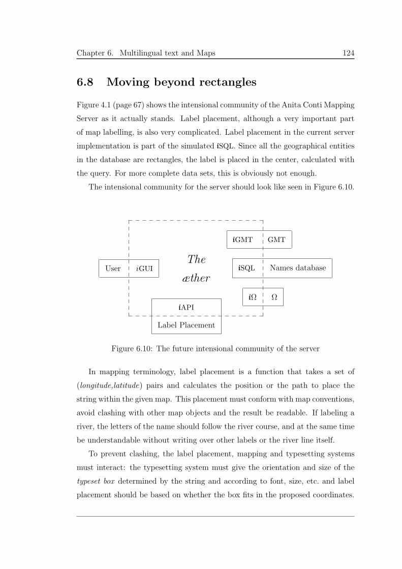
Chapter 6. Multilingual text and Maps 124
6.8 Moving beyond rectangles
Figure 4.1 (page 67) shows the intensional community of the Anita Conti Mapping
Server as it actually stands. Label placement, although a very important part
of map labelling, is also very complicated. Label placement in the current server
implementation is part of the simulated iSQL. Since all the geographical entities
in the database are rectangles, the label is placed in the center, calculated with
the query. For more complete data sets, this is obviously not enough.
The intensional community for the server should look like seen in Figure 6.10.
____________________
_ _ _ _ _ _ _ _ _ _ _ _ _ _ _ _ _ _ _ _
User iGUI iSQL Names database
iGMT GMT
iΩ Ω
The
æther
iAPI
Label Placement
Figure 6.10: The future intensional community of the server
In mapping terminology, label placement is a function that takes a set of
(longitude,latitude) pairs and calculates the position or the path to place the
string within the given map. This placement must conform with map conventions,
avoid clashing with other map objects and the result be readable. If labeling a
river, the letters of the name should follow the river course, and at the same time
be understandable without writing over other labels or the river line itself.
To prevent clashing, the label placement, mapping and typesetting systems
must interact: the typesetting system must give the orientation and size of the
typeset box determined by the string and according to font, size, etc. and label
placement should be based on whether the box fits in the proposed coordinates.
Chapter 6. Multilingual text and Maps 125
The mapping system provides the information about the objects. And so on. This
process is not static and it is mediated through the context. The applications
must negotiate and compromise to guarantee convergence to a solution.
The problem of automatic label placement on its own is huge and far from
being resolved due to the many parameters acting upon single points of maps, let
alone areas. As such, it is the subject of many dissertations and current research
in Geography and Digital Cartography. Placing perfect labels is out of the scope
of this thesis.
Later implementations of the server will delve into searching for existing ap-
proaches and algorithms for label placing, developing the relevant API with the
context, and using the latter as the mediator between applications, by developing
appropriate protocols. Given that the typesetting is done using Ω, there is a lot
of flexibility on the arrangements of the glyphs, as long as there is a complete
specification. Using more advanced algorithms, the mapper should be able to
label linear entities, such as rivers, specified by a list of coordinate pairs.
Chapter 7
Context and Contents Displayed
The devil is in the details
Now that the overall architecture of the Anita Conti Mapping Server has been
presented (Figure 4.1, p. 67), as have the mapping engine and label management
system, we can return to the details of the GUI.
The purpose of this chapter is two-fold. First is the detailed presentation
of the GUI and its implementation subtleties. Second is a demonstration of the
versatility and extensibility of the intensional approach to interface design. These
two aspects are interleaved throughout the chapter, and to better explain and
support them, excerpts of actual code are included at different places.
The sharingBranches of the Anita Conti Mapping Server, explained in Chap-
ter 4 (p.74), are the sections of the context that store user preferences and choices
about the look and content of the map and interface. These are the branches the
user can manipulate, that can be shared among communities of people. The di-
mensions of these branches are accessible to the user and most of the values can
be changed directly from the Web page.
The chapter begins with the initial attempt at creating a Web mapper, in
the ISE language (§7.1); ultimately ISE was not powerful enough because there
was no æther. Instead, the Web page is written in ijsp (§7.2). It provides Web
interfaces for each of the sharingBraches. focusing on the interface branch. Then
126
Chapter 7. Context and Contents Displayed 127
the intensional elements of the Web page (menus, buttons, switches) are de-
fined (§7.3). Then, traversing through the actual page illustrates how each section
uses these elements differently and the necessary processing for each section.
7.1 The first attempt
The first context-aware mapping server for creating versioned maps is imple-
mented using ISE (Intensional Sequential Evaluator, §3.6) as the intensional lan-
guage for the CGI scripts. Although its entry point looks similar to that of the
final version using ijsp, the processing and capabilities are completely different.
The context to be examined by these scripts is passed through the URL, which
becomes the script’s initial context. When the script is invoked, the URL contains
the user’s choices of map and interface values and processes (i.e., requesting a new
version of the map, accessing a database or redisplaying the page with changed
values).
The following code shows the definition of a variable in different languages,
and how this variable is used to output HTML.
1 $<lgIn:en>createMapValue = "Create Map";
2 $<lgIn:fr>createMapValue = "Créez la Carte";
3 $<lgIn:es>createMapValue = "Crear el mapa";
4 $<>createMapValue = $<lgIn:en>createMapValue;
...
10 %[<FORM METHOD="GET">
11 <INPUT NAME=createMap TYPE=submit
12 VALUE="$$createMapValue$$">
...
20 ]%;
In lines 1–4, the variable createMapValue is defined in English, French, Span-
ish and default (<>). This variable stores the text string of the submit button
in the HTML form. Line 4 defines the default value of the string, which is the
value that is chosen when the variable is not defined in the language specified by
the context. In lines 10–20, part of the HTML output is produced. In ISE, text
Chapter 7. Context and Contents Displayed 128
between %[ and ]% is taken verbatim, except when referring to a variable name,
which must be included between double dollar signs ($$), as in line 12. Internally
to ISE, the value of $createMapValue is evaluated by referring to the defined
values and the current context. Assuming that the current context contains
lgIn:es, the language of the interface is requested in Spanish. The definition of
$createMapValue for lgIn:es is found in line 3. Lines 10–12 evalute to
<FORM METHOD="GET">
<INPUT NAME=createMap TYPE=submit
VALUE="Crear el mapa">
The entire Web page is created this way. The mapping server developed using
ISE is a perfect example of an intensional document. It is really multilingualism
in Web pages made easy. And this works not only for language, but for any
other parameter. The page adjusts to the context built from user and system
parameters.
But it presented a significant difficulty, discovered when developing collabo-
ration. Since the complete context must be passed through the URL, no central
location or repository stores the context, giving the possibility to each script
to carry different and perhaps conflicting contexts for the same user. This also
means that most of the code must be in one script, precisely to avoid conflict,
making Web programming even more difficult. So the attempts to share the
context between users become impossible given that there is no central context.
In fact, by passing the context in the URL, the context is being simulated and
neither the server knows the state of the context, nor can the users share it.
There is no æther.
7.2 The actual thing
The solution to fix this problem is to change the development from ISE to ijsp
and use a real æther (the reactive machine) as a centrally stored context. This
æther also supports participants for context sharing among users (Chapter 4).
Chapter 7. Context and Contents Displayed 129
The package ijsp (§3.9) is designed to allow JSP pages access to libintense. The
package allows access to a single instance of the æther, one execution thread at
a time. This avoids several threads (i.e., JSP pages) modifying the æther tree
at the same time and bringing it to an inconsistent state. The ÆtherManager
class implements all of the locking mechanisms necessary to access and modify
the singleton æther.
The statement
AEther CONTEXT = AEtherManager.aether();
initializes the æther instance, and names it context. If this æther instance
already exists, its address is retrieved, assigning to context. (context cor-
responds to the context-space tree-structure explained in Chapter 4.) With this
reference, it can be accessed as shown below:
String theDate = new java.util.Date().toString();
if (CONTEXT.vanilla())
CONTEXT.value("status:dateStamp:created").apply(theDate);
else
CONTEXT.value("status:dateStamp:lastAccess").apply(theDate);
The vanilla() method returns a Boolean value denoting whether context is
empty. The value() method gets a reference to the subcontext under the method
parameter which represents a dimension. The apply() method applies the method
parameter as a single level context operation. This piece of code checks whether
the context has been initialized. If not, it sets the first value, the date stamp for
the creation of the æther. Otherwise, it resets the last accessed date stamp. The
tree corresponding to the status branch is seen in Figure 4.9 (p. 75).
This code is found in the entry point of the Anita Conti Mapping Server,
in startUp.jsp which makes sure that the context is properly initialized, and
that the correct user is accessing the corresponding branch of the æther. This
script forwards to anita.jsp, the script that displays the main Web page. This
is where the “intensional” decisions are made about display.
But let us step back and look at the overall design. The central structure is
the context: it is referred to when processing, displaying, and decision making.
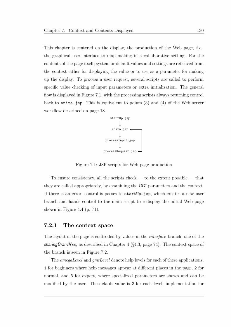
Chapter 7. Context and Contents Displayed 130
This chapter is centered on the display, the production of the Web page, i.e.,
the graphical user interface to map making in a collaborative setting. For the
contents of the page itself, system or default values and settings are retrieved from
the context either for displaying the value or to use as a parameter for making
up the display. To process a user request, several scripts are called to perform
specific value checking of input parameters or extra initialization. The general
flow is displayed in Figure 7.1, with the processing scripts always returning control
back to anita.jsp. This is equivalent to points (3) and (4) of the Web server
workflow described on page 18.
startUp.jsp
anita.jsp
processInput.jsp
processRequest.jsp
Figure 7.1: JSP scripts for Web page production
To ensure consistency, all the scripts check — to the extent possible — that
they are called appropriately, by examining the CGI parameters and the context.
If there is an error, control is passes to startUp.jsp, which creates a new user
branch and hands control to the main script to redisplay the initial Web page
shown in Figure 4.4 (p. 71).
7.2.1 The context space
The layout of the page is controlled by values in the interface branch, one of the
sharingBranch’es, as described in Chapter 4 (§4.3, page 74). The context space of
the branch is seen in Figure 7.2.
The omegaLevel and gmtLevel denote help levels for each of these applications,
1 for beginners where help messages appear at different places in the page, 2 for
normal, and 3 for expert, where specialized parameters are shown and can be
modified by the user. The default value is 2 for each level; implementation for
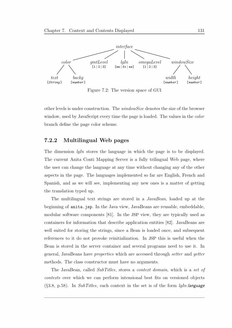
Chapter 7. Context and Contents Displayed 131
interface
color
text[String ]
backg[number ]
gmtLevel[1 | 2 | 3]
lgIn[en | fr | es]
omegaLevel[1 | 2 | 3]
windowSize
width[number ]
height[number ]
Figure 7.2: The version space of GUI
other levels is under construction. The windowSize denotes the size of the browser
window, used by JavaScript every time the page is loaded. The values in the color
branch define the page color scheme.
7.2.2 Multilingual Web pages
The dimension lgIn stores the language in which the page is to be displayed.
The current Anita Conti Mapping Server is a fully trilingual Web page, where
the user can change the language at any time without changing any of the other
aspects in the page. The languages implemented so far are English, French and
Spanish, and as we will see, implementing any new ones is a matter of getting
the translation typed up.
The multilingual text strings are stored in a JavaBean, loaded up at the
beginning of anita.jsp. In the Java view, JavaBeans are reusable, embeddable,
modular software components [81]. In the JSP view, they are typically used as
containers for information that describe application entities [82]. JavaBeans are
well suited for storing the strings, since a Bean is loaded once, and subsequent
references to it do not provoke reinitialization. In JSP this is useful when the
Bean is stored in the server container and several programs need to use it. In
general, JavaBeans have properties which are accessed through setter and getter
methods. The class constructor must have no arguments.
The JavaBean, called SubTitles , stores a context domain, which is a set of
contexts over which we can perform intensional best fits on versioned objects
(§3.8, p.58). In SubTitles , each context in the set is of the form lgIn:language
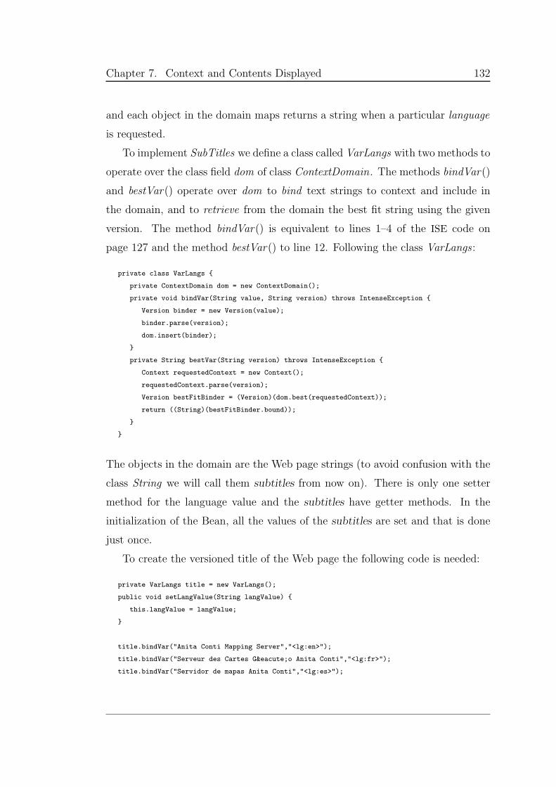
Chapter 7. Context and Contents Displayed 132
and each object in the domain maps returns a string when a particular language
is requested.
To implement SubTitles we define a class called VarLangs with two methods to
operate over the class field dom of class ContextDomain. The methods bindVar()
and bestVar() operate over dom to bind text strings to context and include in
the domain, and to retrieve from the domain the best fit string using the given
version. The method bindVar() is equivalent to lines 1–4 of the ISE code on
page 127 and the method bestVar() to line 12. Following the class VarLangs :
private class VarLangs
private ContextDomain dom = new ContextDomain();
private void bindVar(String value, String version) throws IntenseException
Version binder = new Version(value);
binder.parse(version);
dom.insert(binder);
private String bestVar(String version) throws IntenseException
Context requestedContext = new Context();
requestedContext.parse(version);
Version bestFitBinder = (Version)(dom.best(requestedContext));
return ((String)(bestFitBinder.bound));
The objects in the domain are the Web page strings (to avoid confusion with the
class String we will call them subtitles from now on). There is only one setter
method for the language value and the subtitles have getter methods. In the
initialization of the Bean, all the values of the subtitles are set and that is done
just once.
To create the versioned title of the Web page the following code is needed:
private VarLangs title = new VarLangs();
public void setLangValue(String langValue)
this.langValue = langValue;
title.bindVar("Anita Conti Mapping Server","<lg:en>");
title.bindVar("Serveur des Cartes Géo Anita Conti","<lg:fr>");
title.bindVar("Servidor de mapas Anita Conti","<lg:es>");
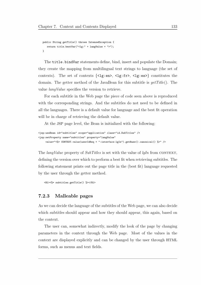
Chapter 7. Context and Contents Displayed 133
public String getTitle() throws IntenseException
return title.bestVar("<lg:" + langValue + ">");
The title.bindVar statements define, bind, insert and populate the Domain;
they create the mapping from multilingual text strings to language (the set of
contexts). The set of contexts <lg:en>, <lg:fr>, <lg:es> constitutes the
domain. The getter method of the JavaBean for this subtitle is getTitle(). The
value langValue specifies the version to retrieve.
For each subtitle in the Web page the piece of code seen above is reproduced
with the corresponding strings. And the subtitles do not need to be defined in
all the languages. There is a default value for language and the best fit operation
will be in charge of retrieving the default value.
At the JSP page level, the Bean is initialized with the following:
<jsp:useBean id="subtitles" scope="application" class="id.SubTitles" />
<jsp:setProperty name="subtitles" property="langValue"
value="<%= CONTEXT.value(userIdReq + ":interface:lgIn").getBase().canonical() %>" />
The langValue property of SubTitles is set with the value of lgIn from context,
defining the version over which to perform a best fit when retrieving subtitles. The
following statement prints out the page title in the (best fit) language requested
by the user through the getter method.
<H1><%= subtitles.getTitle() %></H1>
7.2.3 Malleable pages
As we can decide the language of the subtitles of the Web page, we can also decide
which subtitles should appear and how they should appear, this again, based on
the context.
The user can, somewhat indirectly, modify the look of the page by changing
parameters in the context through the Web page. Most of the values in the
context are displayed explicitly and can be changed by the user through HTML
forms, such as menus and text fields.
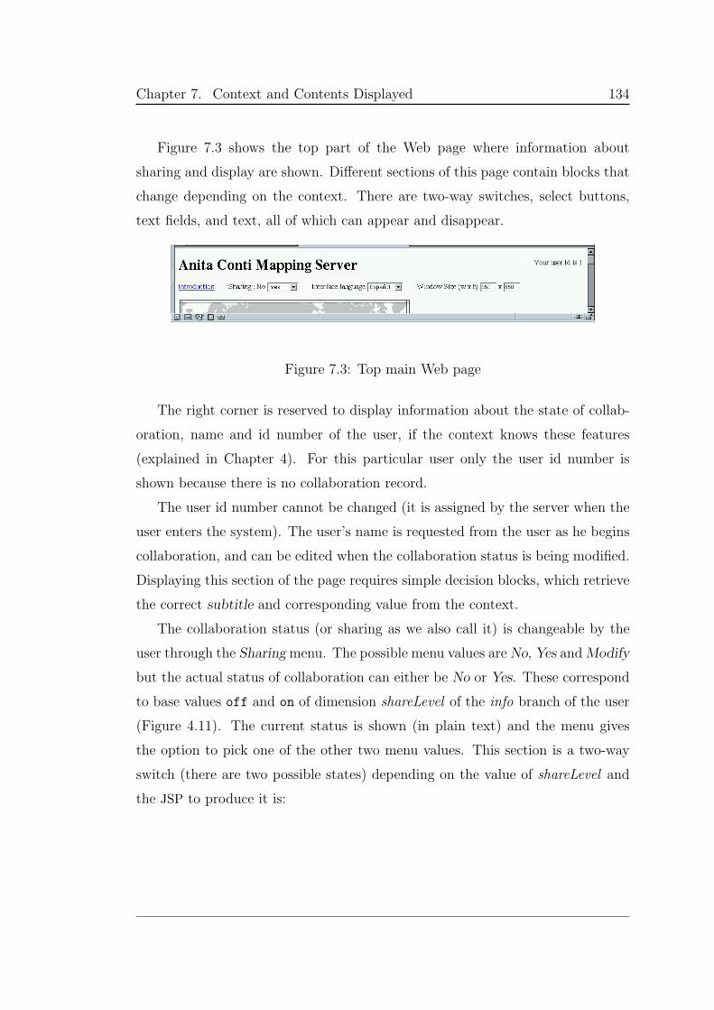
Chapter 7. Context and Contents Displayed 134
Figure 7.3 shows the top part of the Web page where information about
sharing and display are shown. Different sections of this page contain blocks that
change depending on the context. There are two-way switches, select buttons,
text fields, and text, all of which can appear and disappear.
Figure 7.3: Top main Web page
The right corner is reserved to display information about the state of collab-
oration, name and id number of the user, if the context knows these features
(explained in Chapter 4). For this particular user only the user id number is
shown because there is no collaboration record.
The user id number cannot be changed (it is assigned by the server when the
user enters the system). The user’s name is requested from the user as he begins
collaboration, and can be edited when the collaboration status is being modified.
Displaying this section of the page requires simple decision blocks, which retrieve
the correct subtitle and corresponding value from the context.
The collaboration status (or sharing as we also call it) is changeable by the
user through the Sharingmenu. The possible menu values are No, Yes andModify
but the actual status of collaboration can either be No or Yes. These correspond
to base values off and on of dimension shareLevel of the info branch of the user
(Figure 4.11). The current status is shown (in plain text) and the menu gives
the option to pick one of the other two menu values. This section is a two-way
switch (there are two possible states) depending on the value of shareLevel and
the JSP to produce it is:
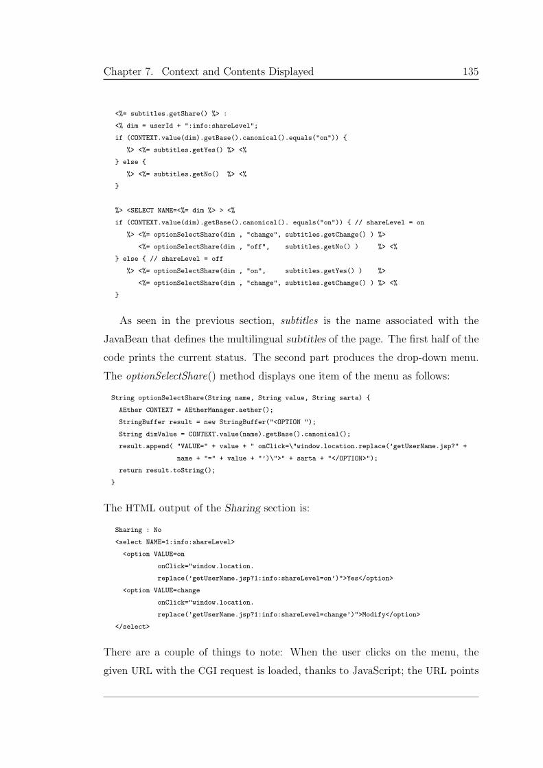
Chapter 7. Context and Contents Displayed 135
<%= subtitles.getShare() %> :
<% dim = userId + ":info:shareLevel";
if (CONTEXT.value(dim).getBase().canonical().equals("on"))
%> <%= subtitles.getYes() %> <%
else
%> <%= subtitles.getNo() %> <%
%> <SELECT NAME=<%= dim %> > <%
if (CONTEXT.value(dim).getBase().canonical(). equals("on")) // shareLevel = on
%> <%= optionSelectShare(dim , "change", subtitles.getChange() ) %>
<%= optionSelectShare(dim , "off", subtitles.getNo() ) %> <%
else // shareLevel = off
%> <%= optionSelectShare(dim , "on", subtitles.getYes() ) %>
<%= optionSelectShare(dim , "change", subtitles.getChange() ) %> <%
As seen in the previous section, subtitles is the name associated with the
JavaBean that defines the multilingual subtitles of the page. The first half of the
code prints the current status. The second part produces the drop-down menu.
The optionSelectShare() method displays one item of the menu as follows:
String optionSelectShare(String name, String value, String sarta)
AEther CONTEXT = AEtherManager.aether();
StringBuffer result = new StringBuffer("<OPTION ");
String dimValue = CONTEXT.value(name).getBase().canonical();
result.append( "VALUE=" + value + " onClick=\"window.location.replace(’getUserName.jsp?" +
name + "=" + value + "’)\">" + sarta + "</OPTION>");
return result.toString();
The HTML output of the Sharing section is:
Sharing : No
<select NAME=1:info:shareLevel>
<option VALUE=on
onClick="window.location.
replace(’getUserName.jsp?1:info:shareLevel=on’)">Yes</option>
<option VALUE=change
onClick="window.location.
replace(’getUserName.jsp?1:info:shareLevel=change’)">Modify</option>
</select>
There are a couple of things to note: When the user clicks on the menu, the
given URL with the CGI request is loaded, thanks to JavaScript; the URL points
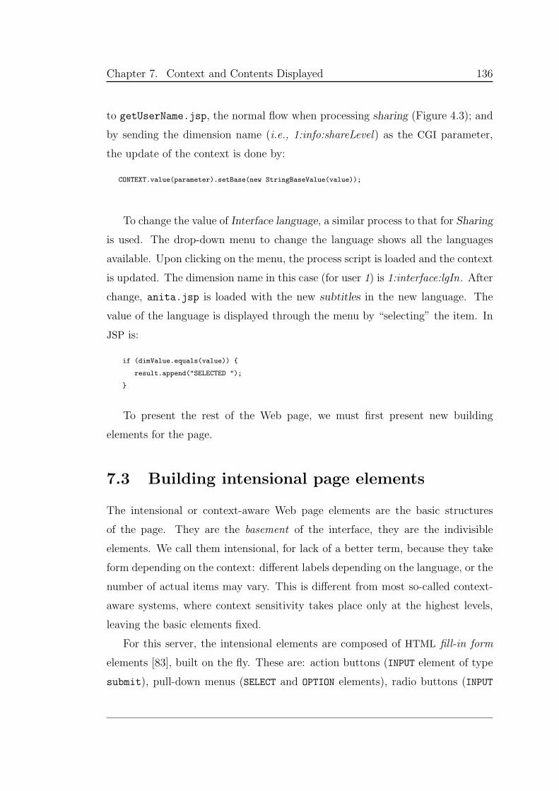
Chapter 7. Context and Contents Displayed 136
to getUserName.jsp, the normal flow when processing sharing (Figure 4.3); and
by sending the dimension name (i.e., 1:info:shareLevel) as the CGI parameter,
the update of the context is done by:
CONTEXT.value(parameter).setBase(new StringBaseValue(value));
To change the value of Interface language, a similar process to that for Sharing
is used. The drop-down menu to change the language shows all the languages
available. Upon clicking on the menu, the process script is loaded and the context
is updated. The dimension name in this case (for user 1) is 1:interface:lgIn. After
change, anita.jsp is loaded with the new subtitles in the new language. The
value of the language is displayed through the menu by “selecting” the item. In
JSP is:
if (dimValue.equals(value))
result.append("SELECTED ");
To present the rest of the Web page, we must first present new building
elements for the page.
7.3 Building intensional page elements
The intensional or context-aware Web page elements are the basic structures
of the page. They are the basement of the interface, they are the indivisible
elements. We call them intensional, for lack of a better term, because they take
form depending on the context: different labels depending on the language, or the
number of actual items may vary. This is different from most so-called context-
aware systems, where context sensitivity takes place only at the highest levels,
leaving the basic elements fixed.
For this server, the intensional elements are composed of HTML fill-in form
elements [83], built on the fly. These are: action buttons (INPUT element of type
submit), pull-down menus (SELECT and OPTION elements), radio buttons (INPUT
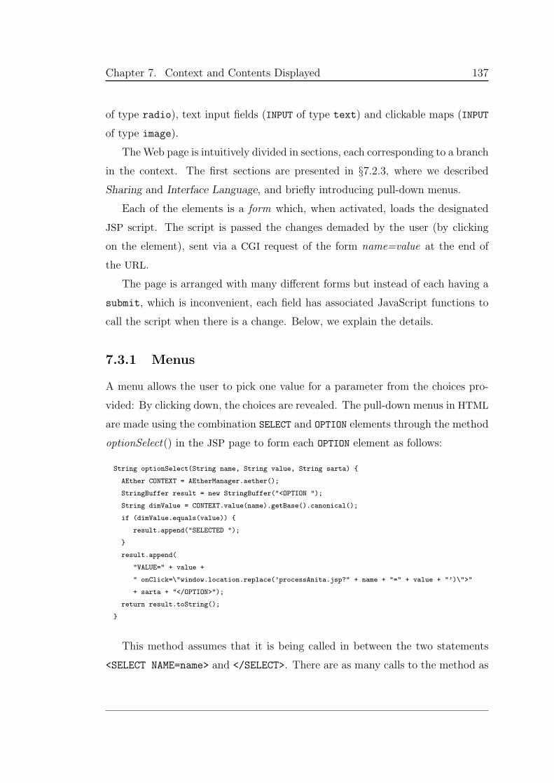
Chapter 7. Context and Contents Displayed 137
of type radio), text input fields (INPUT of type text) and clickable maps (INPUT
of type image).
The Web page is intuitively divided in sections, each corresponding to a branch
in the context. The first sections are presented in §7.2.3, where we described
Sharing and Interface Language, and briefly introducing pull-down menus.
Each of the elements is a form which, when activated, loads the designated
JSP script. The script is passed the changes demaded by the user (by clicking
on the element), sent via a CGI request of the form name=value at the end of
the URL.
The page is arranged with many different forms but instead of each having a
submit, which is inconvenient, each field has associated JavaScript functions to
call the script when there is a change. Below, we explain the details.
7.3.1 Menus
A menu allows the user to pick one value for a parameter from the choices pro-
vided: By clicking down, the choices are revealed. The pull-down menus in HTML
are made using the combination SELECT and OPTION elements through the method
optionSelect() in the JSP page to form each OPTION element as follows:
String optionSelect(String name, String value, String sarta)
AEther CONTEXT = AEtherManager.aether();
StringBuffer result = new StringBuffer("<OPTION ");
String dimValue = CONTEXT.value(name).getBase().canonical();
if (dimValue.equals(value))
result.append("SELECTED ");
result.append(
"VALUE=" + value +
" onClick=\"window.location.replace(’processAnita.jsp?" + name + "=" + value + "’)\">"
+ sarta + "</OPTION>");
return result.toString();
This method assumes that it is being called in between the two statements
<SELECT NAME=name> and </SELECT>. There are as many calls to the method as
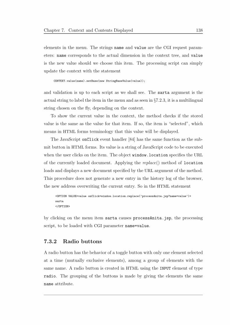
Chapter 7. Context and Contents Displayed 138
elements in the menu. The strings name and value are the CGI request param-
eters: name corresponds to the actual dimension in the context tree, and value
is the new value should we choose this item. The processing script can simply
update the context with the statement
CONTEXT.value(name).setBase(new StringBaseValue(value));
and validation is up to each script as we shall see. The sarta argument is the
actual string to label the item in the menu and as seen in §7.2.3, it is a multilingual
string chosen on the fly, depending on the context.
To show the current value in the context, the method checks if the stored
value is the same as the value for that item. If so, the item is “selected”, which
means in HTML forms terminology that this value will be displayed.
The JavaScript onClick event handler [84] has the same function as the sub-
mit button in HTML forms. Its value is a string of JavaScript code to be executed
when the user clicks on the item. The object window.location specifies the URL
of the currently loaded document. Applying the replace() method of location
loads and displays a new document specified by the URL argument of the method.
This procedure does not generate a new entry in the history log of the browser,
the new address overwriting the current entry. So in the HTML statement
<OPTION VALUE=value onClick=window.location.replace(’processAnita.jsp?name=value’)>
sarta
</OPTION>
by clicking on the menu item sarta causes processAnita.jsp, the processing
script, to be loaded with CGI parameter name=value.
7.3.2 Radio buttons
A radio button has the behavior of a toggle button with only one element selected
at a time (mutually exclusive elements), among a group of elements with the
same name. A radio button is created in HTML using the INPUT element of type
radio. The grouping of the buttons is made by giving the elements the same
name attribute.
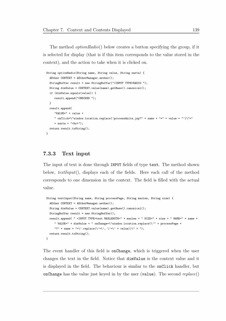
Chapter 7. Context and Contents Displayed 139
The method optionRadio() below creates a button specifying the group, if it
is selected for display (that is if this item corresponds to the value stored in the
context), and the action to take when it is clicked on.
String optionRadio(String name, String value, String sarta)
AEther CONTEXT = AEtherManager.aether();
StringBuffer result = new StringBuffer("<INPUT TYPE=RADIO ");
String dimValue = CONTEXT.value(name).getBase().canonical();
if (dimValue.equals(value))
result.append("CHECKED ");
result.append(
"VALUE=" + value +
" onClick=\"window.location.replace(’processAnita.jsp?" + name + "=" + value + "’)\">"
+ sarta + "<br>");
return result.toString();
7.3.3 Text input
The input of text is done through INPUT fields of type text. The method shown
below, textInput(), displays each of the fields. Here each call of the method
corresponds to one dimension in the context. The field is filled with the actual
value.
String textInput(String name, String processPage, String maxlen, String size)
AEther CONTEXT = AEtherManager.aether();
String dimValue = CONTEXT.value(name).getBase().canonical();
StringBuffer result = new StringBuffer();
result.append( " <INPUT TYPE=text MAXLENGTH=" + maxlen + " SIZE=" + size + " NAME=" + name +
" VALUE=" + dimValue + " onChange=\"window.location.replace(\’" + processPage +
"?" + name + "=\’.replace(\’=\’, \’=\’ + value))\" > ");
return result.toString();
The event handler of this field is onChange, which is triggered when the user
changes the text in the field. Notice that dimValue is the context value and it
is displayed in the field. The behaviour is similar to the onClick handler, but
onChange has the value just keyed in by the user (value). The second replace()
Chapter 7. Context and Contents Displayed 140
method performs a search-and-replace operation on the URL completing the CGI
query request.1
7.4 The Web page
Figure 7.4 shows a snapshot of the Web page displaying default initial values for
a given user. When a data field in the page is changed or clicked on, a JavaScript
handler loads the JSP page associated with the field. The URL of the page
includes the CGI parameters to process and validate the entered data, makes the
needed updates and the script reloads the main Web page.
Figure 7.5 shows a “zoom” of Figure 7.4 of the section just right of the map.
It contains four fields: Map language, Zooming, Update Map and Projection.
The Update Map is the only action button (INPUT element of type submit) of
the intensional elements mentioned in §7.3. This button triggers the production
of a new map, based on the context values. This means that the user can change
the parameters several times before committing himself to create a new map.
The script that processes this action button is makeMap.jsp, sections of which
are mentioned throughout Chapter 5. Basically, this script builds the commands
to make the map based on the context, runs these commands, makes the conver-
sion from PostScript to PNG (Portable Network Graphics, [85]), making the map
available for display to the user in the main Web page. Notice that all of the map
fields, upon change, result in an update of the context only. The change does not
create a new map, since this process is lengthy. This is of course the designer’s
choice and it could be changed if there was a faster process to make maps. In
fact, this is what happens with the interface values: when a value is changed in
the context, the interface is reloaded, taking into account the new values. The
versioned Web page is updated after any relevant change in the context, while
the versioned map is only updated upon user’s request.
1For some reason, the JavaScript statement name + "=value’ )" > " only captures thevalues keyed in as opposed to the value in the field. The statement name + "=’.replace(’=’,
’=’ + value))" > " needs to be used instead.
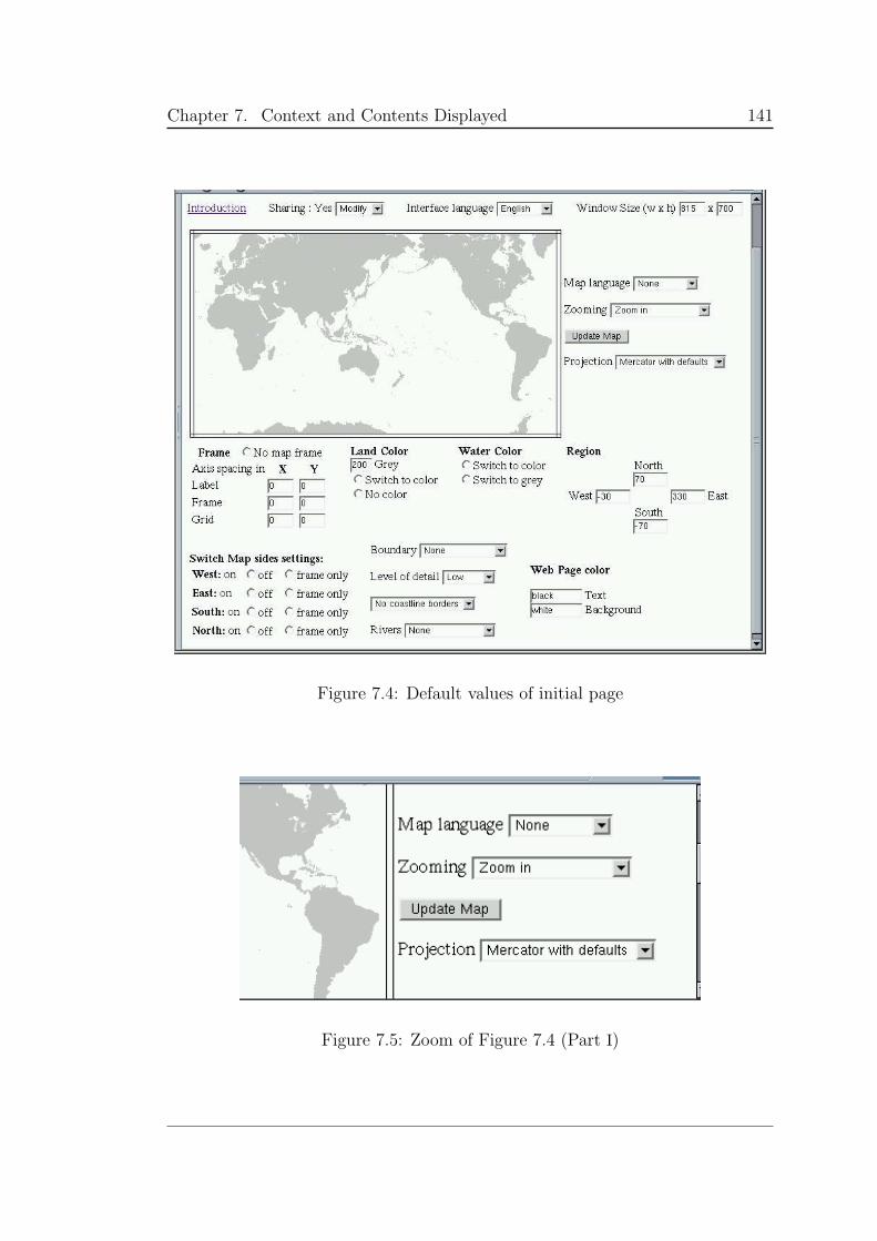
Chapter 7. Context and Contents Displayed 141
Figure 7.4: Default values of initial page
Figure 7.5: Zoom of Figure 7.4 (Part I)
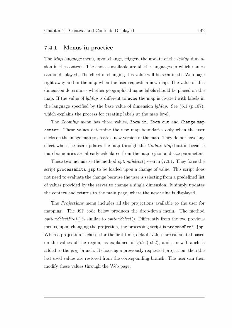
Chapter 7. Context and Contents Displayed 142
7.4.1 Menus in practice
The Map language menu, upon change, triggers the update of the lgMap dimen-
sion in the context. The choices available are all the languages in which names
can be displayed. The effect of changing this value will be seen in the Web page
right away and in the map when the user requests a new map. The value of this
dimension determines whether geographical name labels should be placed on the
map. If the value of lgMap is different to none the map is created with labels in
the language specified by the base value of dimension lgMap. See §6.1 (p.107),
which explains the process for creating labels at the map level.
The Zooming menu has three values, Zoom in, Zoom out and Change map
center. These values determine the new map boundaries only when the user
clicks on the image map to create a new version of the map. They do not have any
effect when the user updates the map through the Update Map button because
map boundaries are already calculated from the map region and size parameters.
These two menus use the method optionSelect() seen in §7.3.1. They force the
script processAnita.jsp to be loaded upon a change of value. This script does
not need to evaluate the change because the user is selecting from a predefined list
of values provided by the server to change a single dimension. It simply updates
the context and returns to the main page, where the new value is displayed.
The Projections menu includes all the projections available to the user for
mapping. The JSP code below produces the drop-down menu. The method
optionSelectProj () is similar to optionSelect(). Differently from the two previous
menus, upon changing the projection, the processing script is processProj.jsp.
When a projection is chosen for the first time, default values are calculated based
on the values of the region, as explained in §5.2 (p.92), and a new branch is
added to the proj branch. If choosing a previously requested projection, then the
last used values are restored from the corresponding branch. The user can then
modify these values through the Web page.
Chapter 7. Context and Contents Displayed 143
Projection
<% dim = userId + ":gmt:proj"; %>
<SELECT NAME=<%= dim %>>
<%= optionSelectProj(dim, "1:M", "Mercator with defaults" ) %>
<%= optionSelectProj(dim, "2:J", "Miller" ) %>
<%= optionSelectProj(dim, "2:Q", "Equidistant" ) %>
<%= optionSelectProj(dim, "2:H", "Hammer" ) %>
<%= optionSelectProj(dim, "2:I", "Sinusoidal" ) %>
<%= optionSelectProj(dim, "2:Kf", "Eckert IV" ) %>
<%= optionSelectProj(dim, "2:Ks", "Eckert VI" ) %>
<%= optionSelectProj(dim, "2:N", "Robinson" ) %>
<%= optionSelectProj(dim, "2:R", "Winkel Tripel" ) %>
<%= optionSelectProj(dim, "2:V", "Van der Grinten" ) %>
<%= optionSelectProj(dim, "2:W", "Mollweide" ) %>
<%= optionSelectProj(dim, "3:A", "Lambert azimuthal" ) %>
<%= optionSelectProj(dim, "3:E", "Azimuthal equidistant" ) %>
<%= optionSelectProj(dim, "3:G", "Azimuthal ortographic" ) %>
<%= optionSelectProj(dim, "3:S", "General stereographic" ) %>
<%= optionSelectProj(dim, "3:C", "Cassini" ) %>
<%= optionSelectProj(dim, "4:M", "Mercator" ) %>
<%= optionSelectProj(dim, "4:T", "Transverse Mercator" ) %>
<%= optionSelectProj(dim, "4:Y", "General Cylindrical" ) %>
<%= optionSelectProj(dim, "5:Ob", "Oblique Mercator" ) %>
<%= optionSelectProj(dim, "5:Oc", "Oblique Mercator: origin/pole" ) %>
<%= optionSelectProj(dim, "6:B", "Albers" ) %>
<%= optionSelectProj(dim, "6:D", "Equidistant conic" ) %>
<%= optionSelectProj(dim, "6:L", "Lambert conic" ) %>
</SELECT>
7.4.2 Multicase display
The version space of the projection branch is seen in Figure 5.4 (p.94). From the
previous section, an actual user may have several projectionClass type branches
(1, 2, 3, 4, 5, 6 or 7 ), each with several branching projections (projection j in
Figure 5.3, p.93). The base value of proj indicates the branch to use, hence
the projection that is active. This follows more or less with the function of the
.gmtcommands file, where previous values of projection arguments are saved and
the one to use is stated in the command line (§5.1, p.88).
The division of the projections in projectionClasses is based on the number and
type of the parameters needed to use each projection in GMT (Table 5.2, p.93).
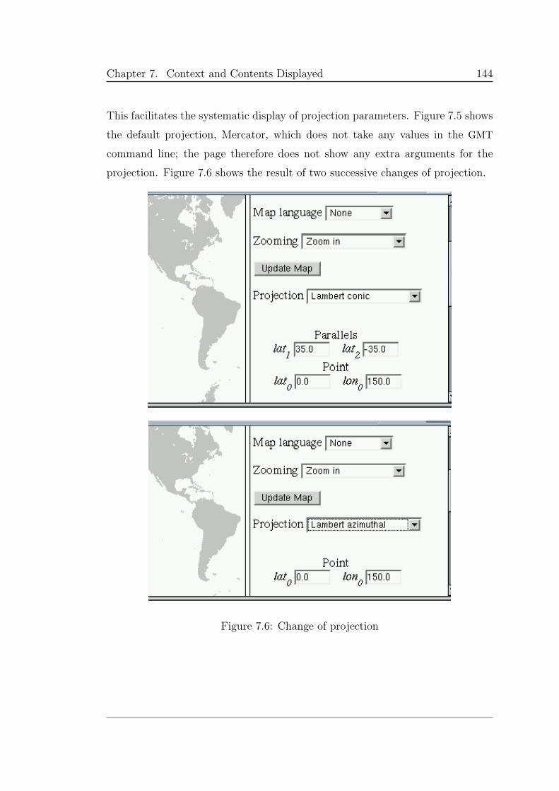
Chapter 7. Context and Contents Displayed 144
This facilitates the systematic display of projection parameters. Figure 7.5 shows
the default projection, Mercator, which does not take any values in the GMT
command line; the page therefore does not show any extra arguments for the
projection. Figure 7.6 shows the result of two successive changes of projection.
Figure 7.6: Change of projection
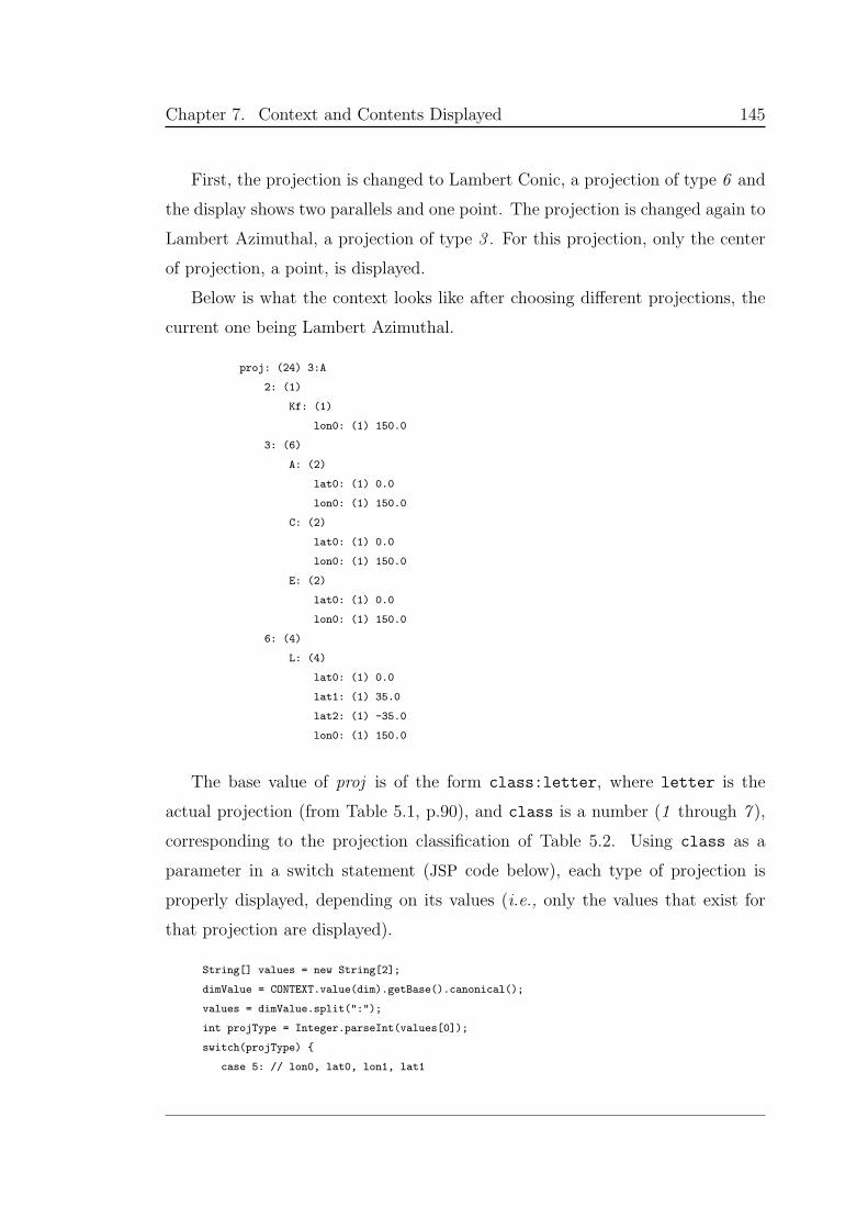
Chapter 7. Context and Contents Displayed 145
First, the projection is changed to Lambert Conic, a projection of type 6 and
the display shows two parallels and one point. The projection is changed again to
Lambert Azimuthal, a projection of type 3 . For this projection, only the center
of projection, a point, is displayed.
Below is what the context looks like after choosing different projections, the
current one being Lambert Azimuthal.
proj: (24) 3:A
2: (1)
Kf: (1)
lon0: (1) 150.0
3: (6)
A: (2)
lat0: (1) 0.0
lon0: (1) 150.0
C: (2)
lat0: (1) 0.0
lon0: (1) 150.0
E: (2)
lat0: (1) 0.0
lon0: (1) 150.0
6: (4)
L: (4)
lat0: (1) 0.0
lat1: (1) 35.0
lat2: (1) -35.0
lon0: (1) 150.0
The base value of proj is of the form class:letter, where letter is the
actual projection (from Table 5.1, p.90), and class is a number (1 through 7 ),
corresponding to the projection classification of Table 5.2. Using class as a
parameter in a switch statement (JSP code below), each type of projection is
properly displayed, depending on its values (i.e., only the values that exist for
that projection are displayed).
String[] values = new String[2];
dimValue = CONTEXT.value(dim).getBase().canonical();
values = dimValue.split(":");
int projType = Integer.parseInt(values[0]);
switch(projType)
case 5: // lon0, lat0, lon1, lat1
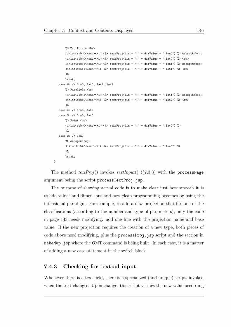
Chapter 7. Context and Contents Displayed 146
%> Two Points <br>
<i>lon<sub>0</sub></i> <%= textProj(dim + ":" + dimValue + ":lon0") %>
<i>lat<sub>0</sub></i> <%= textProj(dim + ":" + dimValue + ":lat0") %> <br>
<i>lon<sub>1</sub></i> <%= textProj(dim + ":" + dimValue + ":lon1") %>
<i>lat<sub>1</sub></i> <%= textProj(dim + ":" + dimValue + ":lat1") %> <br>
<%
break;
case 6: // lon0, lat0, lat1, lat2
%> Parallels <br>
<i>lat<sub>1</sub></i> <%= textProj(dim + ":" + dimValue + ":lat1") %>
<i>lat<sub>2</sub></i> <%= textProj(dim + ":" + dimValue + ":lat2") %> <br>
<%
case 4: // lon0, lats
case 3: // lon0, lat0
%> Point <br>
<i>lat<sub>0</sub></i> <%= textProj(dim + ":" + dimValue + ":lat0") %>
<%
case 2: // lon0
%>
<i>lon<sub>0</sub></i> <%= textProj(dim + ":" + dimValue + ":lon0") %>
<%
break;
The method textProj () invokes textInput() (§7.3.3) with the processPage
argument being the script processTextProj.jsp.
The purpose of showing actual code is to make clear just how smooth it is
to add values and dimensions and how clean programming becomes by using the
intensional paradigm. For example, to add a new projection that fits one of the
classifications (according to the number and type of parameters), only the code
in page 143 needs modifying: add one line with the projection name and base
value. If the new projection requires the creation of a new type, both pieces of
code above need modifying, plus the processProj.jsp script and the section in
makeMap.jsp where the GMT command is being built. In each case, it is a matter
of adding a new case statement in the switch block.
7.4.3 Checking for textual input
Whenever there is a text field, there is a specialized (and unique) script, invoked
when the text changes. Upon change, this script verifies the new value according
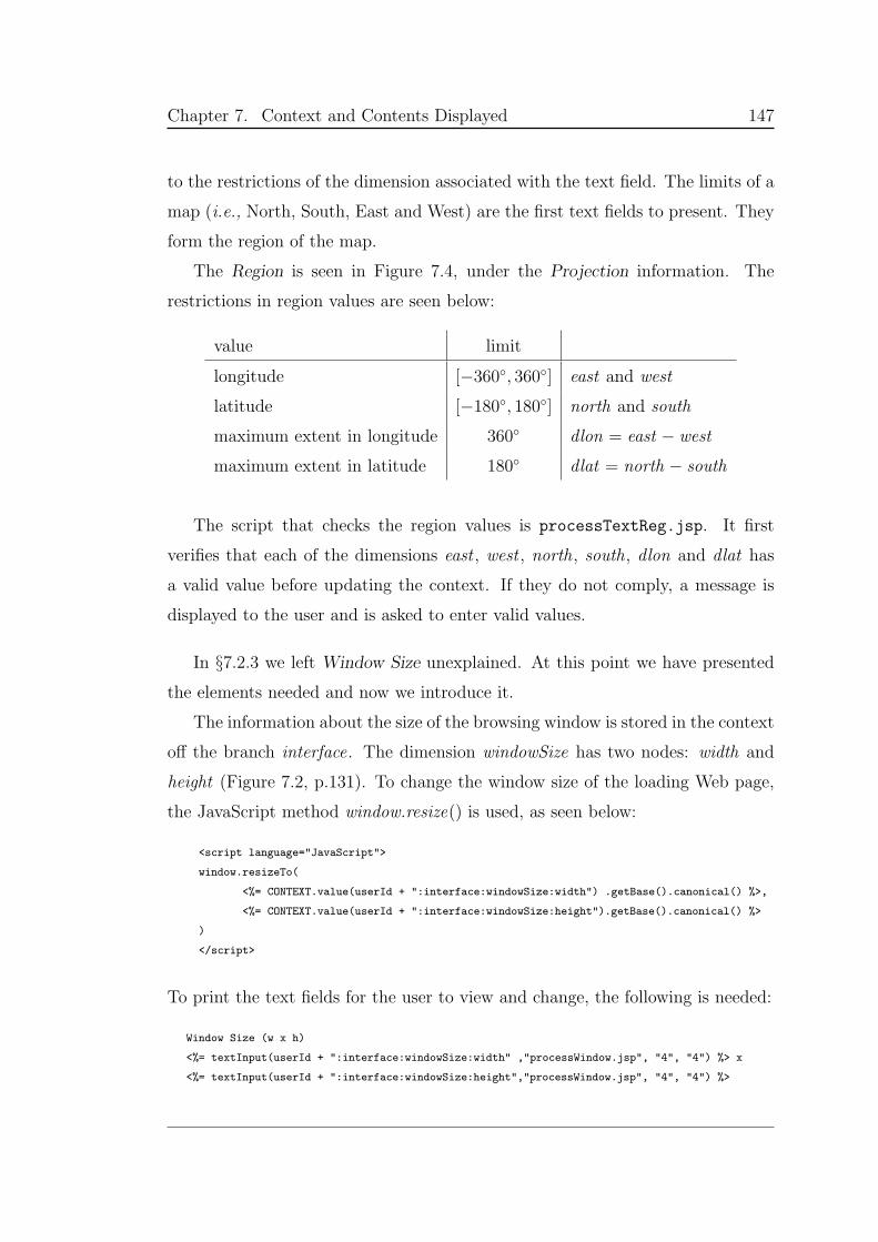
Chapter 7. Context and Contents Displayed 147
to the restrictions of the dimension associated with the text field. The limits of a
map (i.e., North, South, East and West) are the first text fields to present. They
form the region of the map.
The Region is seen in Figure 7.4, under the Projection information. The
restrictions in region values are seen below:
value limit
longitude [−360, 360] east and west
latitude [−180, 180] north and south
maximum extent in longitude 360 dlon = east − west
maximum extent in latitude 180 dlat = north − south
The script that checks the region values is processTextReg.jsp. It first
verifies that each of the dimensions east , west , north, south, dlon and dlat has
a valid value before updating the context. If they do not comply, a message is
displayed to the user and is asked to enter valid values.
In §7.2.3 we left Window Size unexplained. At this point we have presented
the elements needed and now we introduce it.
The information about the size of the browsing window is stored in the context
off the branch interface. The dimension windowSize has two nodes: width and
height (Figure 7.2, p.131). To change the window size of the loading Web page,
the JavaScript method window.resize() is used, as seen below:
<script language="JavaScript">
window.resizeTo(
<%= CONTEXT.value(userId + ":interface:windowSize:width") .getBase().canonical() %>,
<%= CONTEXT.value(userId + ":interface:windowSize:height").getBase().canonical() %>
)
</script>
To print the text fields for the user to view and change, the following is needed:
Window Size (w x h)
<%= textInput(userId + ":interface:windowSize:width" ,"processWindow.jsp", "4", "4") %> x
<%= textInput(userId + ":interface:windowSize:height","processWindow.jsp", "4", "4") %>
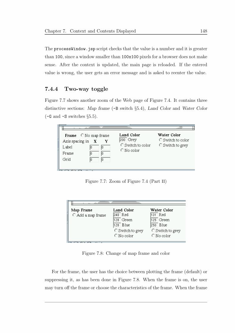
Chapter 7. Context and Contents Displayed 148
The processWindow.jsp script checks that the value is a number and it is greater
than 100, since a window smaller than 100x100 pixels for a browser does not make
sense. After the context is updated, the main page is reloaded. If the entered
value is wrong, the user gets an error message and is asked to reenter the value.
7.4.4 Two-way toggle
Figure 7.7 shows another zoom of the Web page of Figure 7.4. It contains three
distinctive sections: Map frame (-B switch §5.4), Land Color and Water Color
(-G and -S switches §5.5).
Figure 7.7: Zoom of Figure 7.4 (Part II)
Figure 7.8: Change of map frame and color
For the frame, the user has the choice between plotting the frame (default) or
suppressing it, as has been done in Figure 7.8. When the frame is on, the user
may turn off the frame or choose the characteristics of the frame. When the frame
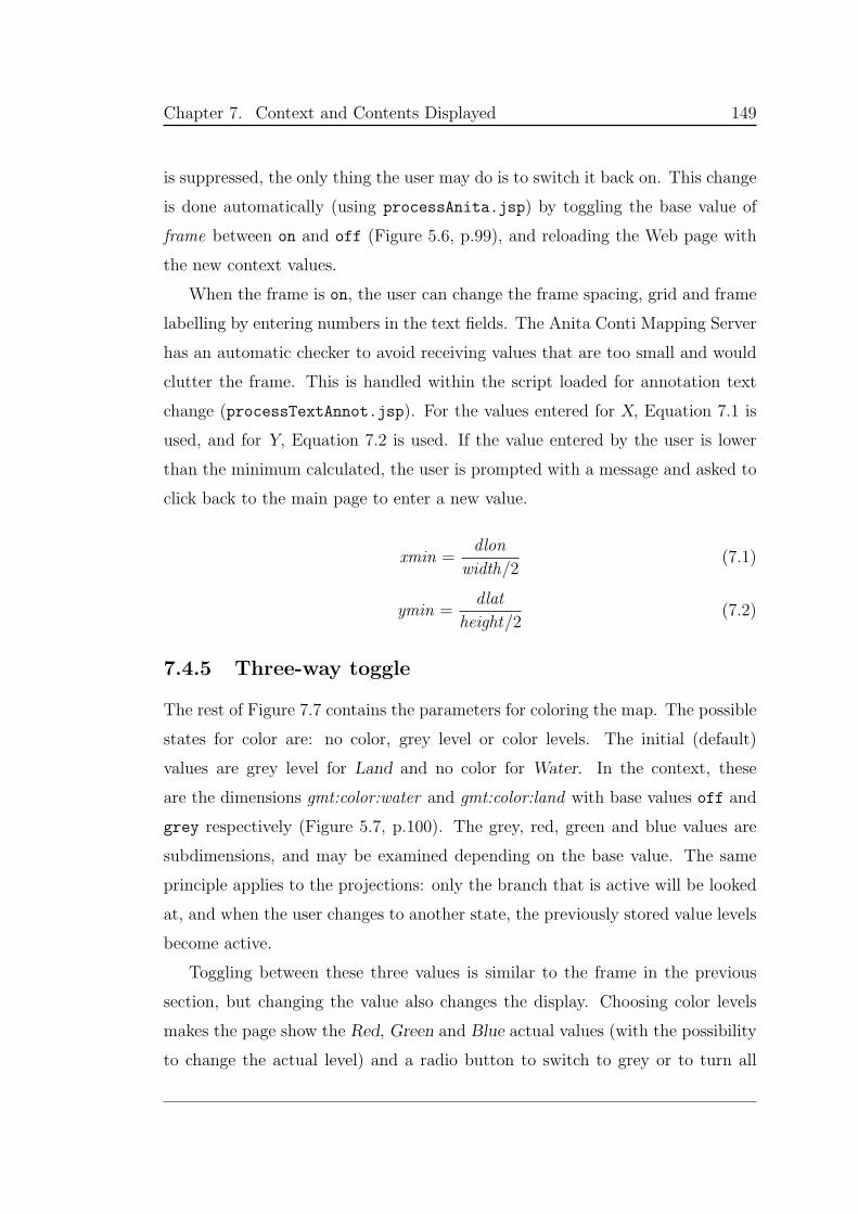
Chapter 7. Context and Contents Displayed 149
is suppressed, the only thing the user may do is to switch it back on. This change
is done automatically (using processAnita.jsp) by toggling the base value of
frame between on and off (Figure 5.6, p.99), and reloading the Web page with
the new context values.
When the frame is on, the user can change the frame spacing, grid and frame
labelling by entering numbers in the text fields. The Anita Conti Mapping Server
has an automatic checker to avoid receiving values that are too small and would
clutter the frame. This is handled within the script loaded for annotation text
change (processTextAnnot.jsp). For the values entered for X, Equation 7.1 is
used, and for Y, Equation 7.2 is used. If the value entered by the user is lower
than the minimum calculated, the user is prompted with a message and asked to
click back to the main page to enter a new value.
xmin =dlon
width/2(7.1)
ymin =dlat
height/2(7.2)
7.4.5 Three-way toggle
The rest of Figure 7.7 contains the parameters for coloring the map. The possible
states for color are: no color, grey level or color levels. The initial (default)
values are grey level for Land and no color for Water. In the context, these
are the dimensions gmt:color:water and gmt:color:land with base values off and
grey respectively (Figure 5.7, p.100). The grey, red, green and blue values are
subdimensions, and may be examined depending on the base value. The same
principle applies to the projections: only the branch that is active will be looked
at, and when the user changes to another state, the previously stored value levels
become active.
Toggling between these three values is similar to the frame in the previous
section, but changing the value also changes the display. Choosing color levels
makes the page show the Red, Green and Blue actual values (with the possibility
to change the actual level) and a radio button to switch to grey or to turn all
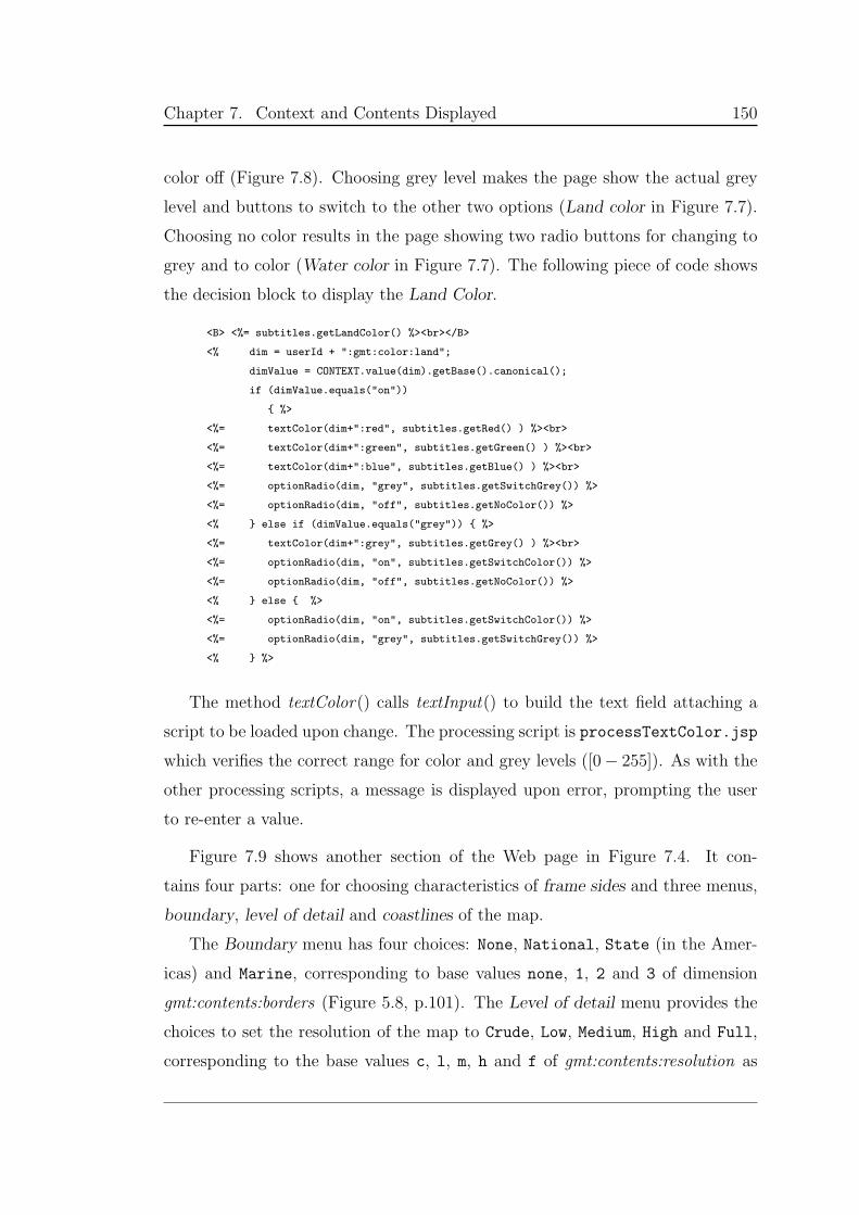
Chapter 7. Context and Contents Displayed 150
color off (Figure 7.8). Choosing grey level makes the page show the actual grey
level and buttons to switch to the other two options (Land color in Figure 7.7).
Choosing no color results in the page showing two radio buttons for changing to
grey and to color (Water color in Figure 7.7). The following piece of code shows
the decision block to display the Land Color.
<B> <%= subtitles.getLandColor() %><br></B>
<% dim = userId + ":gmt:color:land";
dimValue = CONTEXT.value(dim).getBase().canonical();
if (dimValue.equals("on"))
%>
<%= textColor(dim+":red", subtitles.getRed() ) %><br>
<%= textColor(dim+":green", subtitles.getGreen() ) %><br>
<%= textColor(dim+":blue", subtitles.getBlue() ) %><br>
<%= optionRadio(dim, "grey", subtitles.getSwitchGrey()) %>
<%= optionRadio(dim, "off", subtitles.getNoColor()) %>
<% else if (dimValue.equals("grey")) %>
<%= textColor(dim+":grey", subtitles.getGrey() ) %><br>
<%= optionRadio(dim, "on", subtitles.getSwitchColor()) %>
<%= optionRadio(dim, "off", subtitles.getNoColor()) %>
<% else %>
<%= optionRadio(dim, "on", subtitles.getSwitchColor()) %>
<%= optionRadio(dim, "grey", subtitles.getSwitchGrey()) %>
<% %>
The method textColor() calls textInput() to build the text field attaching a
script to be loaded upon change. The processing script is processTextColor.jsp
which verifies the correct range for color and grey levels ([0− 255]). As with the
other processing scripts, a message is displayed upon error, prompting the user
to re-enter a value.
Figure 7.9 shows another section of the Web page in Figure 7.4. It con-
tains four parts: one for choosing characteristics of frame sides and three menus,
boundary, level of detail and coastlines of the map.
The Boundary menu has four choices: None, National, State (in the Amer-
icas) and Marine, corresponding to base values none, 1, 2 and 3 of dimension
gmt:contents:borders (Figure 5.8, p.101). The Level of detail menu provides the
choices to set the resolution of the map to Crude, Low, Medium, High and Full,
corresponding to the base values c, l, m, h and f of gmt:contents:resolution as
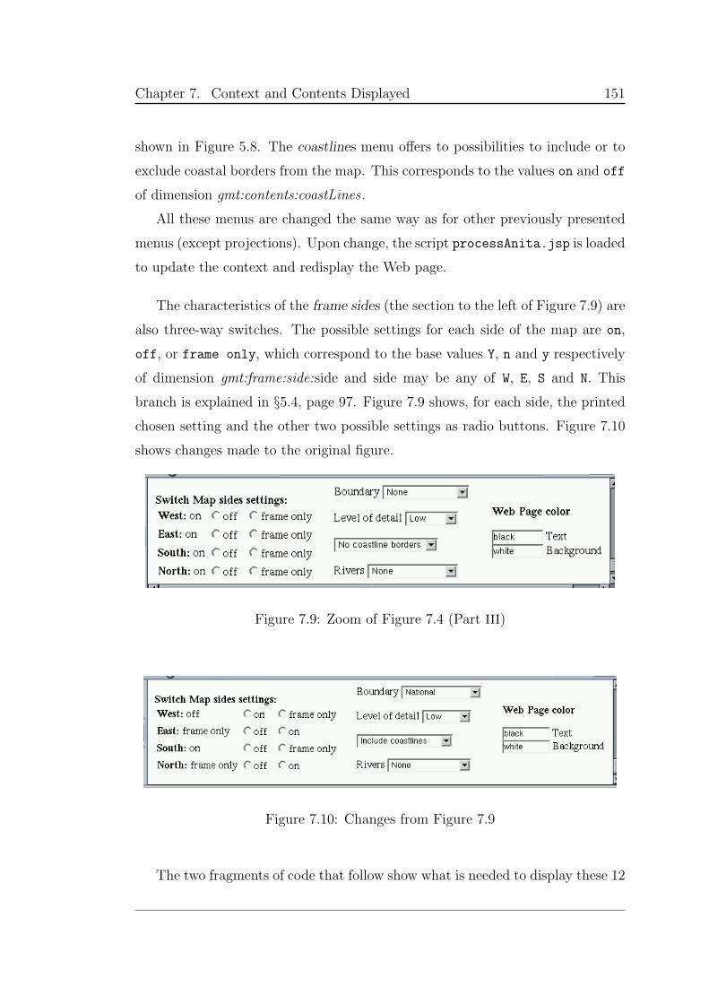
Chapter 7. Context and Contents Displayed 151
shown in Figure 5.8. The coastlines menu offers to possibilities to include or to
exclude coastal borders from the map. This corresponds to the values on and off
of dimension gmt:contents:coastLines.
All these menus are changed the same way as for other previously presented
menus (except projections). Upon change, the script processAnita.jsp is loaded
to update the context and redisplay the Web page.
The characteristics of the frame sides (the section to the left of Figure 7.9) are
also three-way switches. The possible settings for each side of the map are on,
off, or frame only, which correspond to the base values Y, n and y respectively
of dimension gmt:frame:side:side and side may be any of W, E, S and N. This
branch is explained in §5.4, page 97. Figure 7.9 shows, for each side, the printed
chosen setting and the other two possible settings as radio buttons. Figure 7.10
shows changes made to the original figure.
Figure 7.9: Zoom of Figure 7.4 (Part III)
Figure 7.10: Changes from Figure 7.9
The two fragments of code that follow show what is needed to display these 12
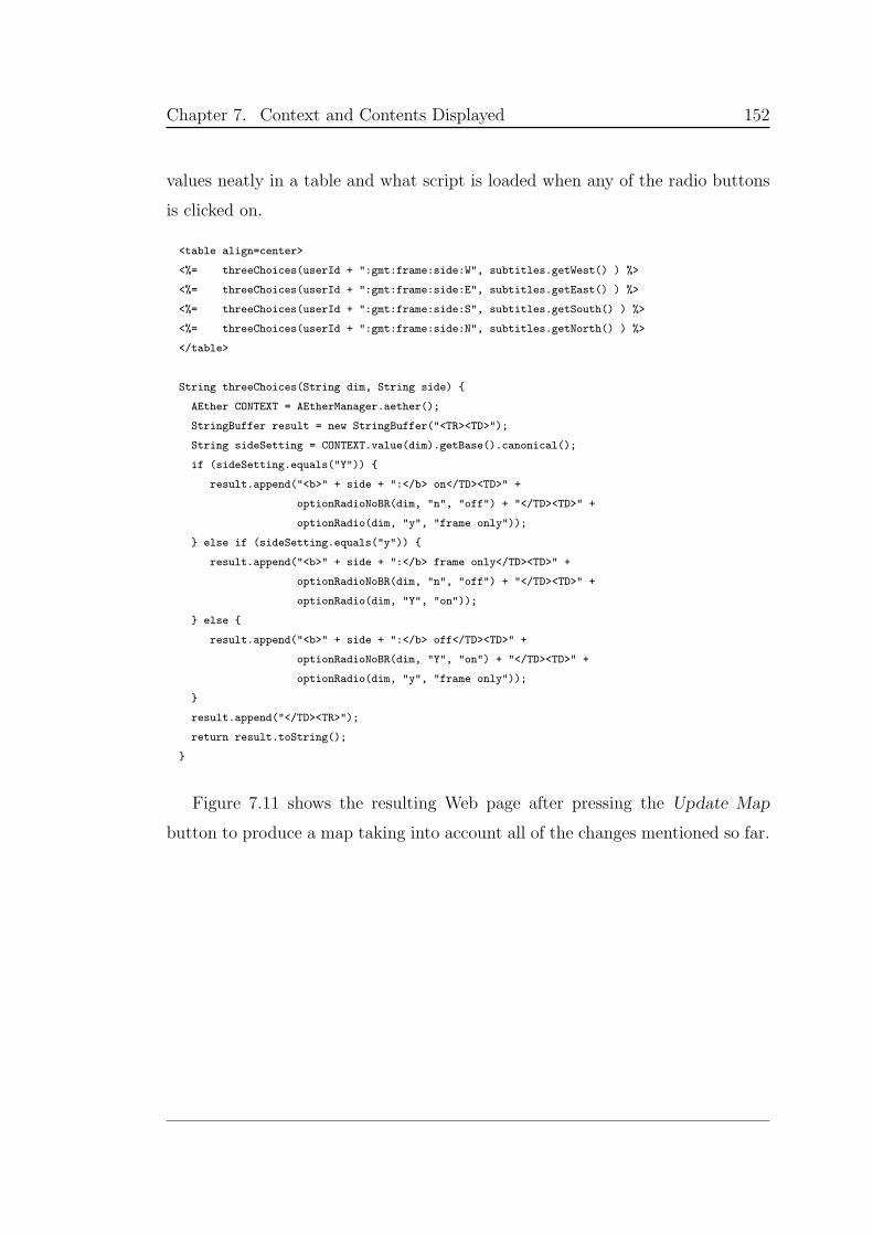
Chapter 7. Context and Contents Displayed 152
values neatly in a table and what script is loaded when any of the radio buttons
is clicked on.
<table align=center>
<%= threeChoices(userId + ":gmt:frame:side:W", subtitles.getWest() ) %>
<%= threeChoices(userId + ":gmt:frame:side:E", subtitles.getEast() ) %>
<%= threeChoices(userId + ":gmt:frame:side:S", subtitles.getSouth() ) %>
<%= threeChoices(userId + ":gmt:frame:side:N", subtitles.getNorth() ) %>
</table>
String threeChoices(String dim, String side)
AEther CONTEXT = AEtherManager.aether();
StringBuffer result = new StringBuffer("<TR><TD>");
String sideSetting = CONTEXT.value(dim).getBase().canonical();
if (sideSetting.equals("Y"))
result.append("<b>" + side + ":</b> on</TD><TD>" +
optionRadioNoBR(dim, "n", "off") + "</TD><TD>" +
optionRadio(dim, "y", "frame only"));
else if (sideSetting.equals("y"))
result.append("<b>" + side + ":</b> frame only</TD><TD>" +
optionRadioNoBR(dim, "n", "off") + "</TD><TD>" +
optionRadio(dim, "Y", "on"));
else
result.append("<b>" + side + ":</b> off</TD><TD>" +
optionRadioNoBR(dim, "Y", "on") + "</TD><TD>" +
optionRadio(dim, "y", "frame only"));
result.append("</TD><TR>");
return result.toString();
Figure 7.11 shows the resulting Web page after pressing the Update Map
button to produce a map taking into account all of the changes mentioned so far.

Chapter 7. Context and Contents Displayed 153
Figure 7.11: The updated map after all the changes
Chapter 7. Context and Contents Displayed 154
7.5 Clickable maps
The Anita Conti Mapping Server supports what is known as clickable maps: by
a mouse click on the image map, the map is either zoomed in, zoomed out or
center changed, features determined by Zooming value.
Using the INPUT element of type image, the image becomes alive. Clicking on
the map immediately submits the CGI query request to the makeMapFromXY.jsp
script, including the coordinates of the mouse pointer, measured in pixels from
the upper left-hand corner of the image. The coordinates are sent in two pairs of
the form: x=xval & y=yval .
The script makeMapFromXY.jsp processes the (xval , yval) coordinates. It calls
a GMT function to convert the point into geographical coordinates (lon, lat), and
with the Equations below, it calculates the new region of the map. (Note that
zoom expresses a zooming level — 1 for zoom in, 2 for repositioning, 4 for zoom
out — and does not correspond to an image enlargement factor.)
west = lon −dlon
zoom(7.3)
east = lon +dlon
zoom(7.4)
south = lat −dlat
zoom(7.5)
north = lat +dlat
zoom(7.6)
The values lon and lat are the just calculated geographical coordinates. The
values of dlat and dlon are taken from the context as well as zoom. This last one is
updated from the Zooming menu, which as seen in the begining of this chapter,
has three possible values: Zoom in, Zoom out and Change map center. These
values correspond to base values 4 , 1 and 2 of the gmt:proj:zoom dimension.
Once the context is updated with the correct values, control is passed to the
makeMap.jsp script which builds the map and reloads the main page.
Chapter 7. Context and Contents Displayed 155
7.6 Summary
The Anita Conti Mapping Server supports a versioned document within another
versioned document, interacting and influencing each other. The Web page
changes upon a user’s requests and accepts changes for the map parameters.
Upon map creation, the Web page must adjust to the new images and to the new
context values.
So far, we have referred to using the computer screen, whose size can be
adjusted through the Web page. But, should the hardware device change, (e.g.,
PDA, mobile phones) so should the values referring to output. With these small
devices there is no point in producing high resolution maps (waste of processing)
or color maps (cannot display them).
In the case of a system with heterogenous parts, we want to have the ability
to choose the appropriate application for dedicated tasks. In a sophisticated
mapping system for example, I want to have choices about the method to display
my data for analysis. If I need to analyze product sales by region, the system
should offer a GIS tool, and if I need to study different types of vegetation, it
should offer a thematic mapper.
The approach is the same as with the Anita Conti Mapping Server: parame-
trize each of the applications and integrate it into the context space. The API
must define what are the relevant parameters and a suite of processes must be
created to do what the system needs. On similar tools, certain parameters are
the same (a region of a map will be the same regardless of the mapper) and we
need to maintain data integrity, achieved through using the context as the central
repository.
Chapter 8
The Future of Internet Mapping
And at the end there is. . .
a whole new world
The Anita Conti Mapping Server is an infrastructure that provides the means
for producing maps collaboratively in a way that no other system can offer. The
server is a fully working system that can be used by anyone with Web access,
provided JavaScript and Java applets are enabled. Nevertheless, the server is still
only a prototype, which should be extended in many directions, to support both
sophisticated mapping experts trying to use the latest tools and data, as well as
lay users who are just looking for some information.
This chapter summarizes the major contributions of this thesis, and explains
the different directions possible for a new way to look at mapping. The extensions
and enhancements range from basic interface issues to the further intensionaliza-
tion of existing software to the social organization required to build free datasets
with similar properties to those of free software.
8.1 Contributions
The Anita Conti Mapping Server is the first large-scale experiment in intensional
design. In so doing, I developed the means for programming multisharing, in
which a user can simultaneously “be” in several different contexts; It is like a user
156
Chapter 8. The Future of Internet Mapping 157
being in several different communities at the same time. The personal context
for this user will normally be different from the personal context of other users
in each of the multiple communities.
The design of the server also led to the concept of the “Intensional API”. For
each application, an API is made to the context, and this application can then be
seen as part of the context, and the rest of the system need not interact directly
with the original application. As a result, applications of diverse nature can be
brought together for new tasks. In addition, sharing between users can then
take place at the level of the actions of the software components; collaboration
becomes more than just talk.
The Web interface of the server places on the same page the means for re-
questing new maps as well as the last generated map, as well as general control of
the page look itself. It is the context that summarizes the details of these differ-
ent parts. In building the page, I was able to create a complex page with many
parameters, without sacrificing modularity or legibility. Adding new entities to
the interface can be done without any problems.
Finally, for the storage of data varying in multiple directions, I have pro-
posed the intensional relational database, giving the syntax and semantics for an
intensional relational algebra and the syntax for iSQL.
8.2 Interface improvements
The enhancements of the next sections all need long-term interface work. Here
are some short-term additions:
• Add user personal profile managers and activity history logs.
• Provide more choices to the cartographer and typesetter expert. For ex-
ample, the typetter wants to have complete control on the script, direction
and font used to print the labels.
• Implement the no-activity functionality using the status:dateStamp dimen-
sion (§4.3.1 p.75). This involves freeing the server of memory by pruning
Chapter 8. The Future of Internet Mapping 158
user and æther branches that have not been used for a determined period
of time, labelling them as inactive.
• Optimize the process of map making by introducing the notion of versioned
layers (making up versioned maps). If the map is composed of layers rebuilt
independently, only the layers affected by a change of context are rebuilt
when a new map is requested. For example, a map consists of two layers,
one of which is for the labels. Changing the language of the labels only
affects that layer, so only it should be recalculated. This will speed up the
server and be more efficient in storage. This can be viewed as some sort of
eduction where layers tagged with subcontexts are stored in a warehouse.
The mapper would be faster by reusing layers.
8.3 Developing new functionality
There are two ways in which functionality can be added to the server. First,
new applications can be taken as black boxes and integrated into the context
through the design of an Intensional API. Second, existing applications can be
intensionalized, where their source code is modified to be more context-aware,
and to reduce the granularity and to improve the modularity of the system.
8.3.1 Map related functions
As mentioned in Chapter 5, the GMT suite includes about 60 functions. However,
in the current implementation of Anita Conti Mapping Server, only one is used:
pscoast (plus psomega, developed for this thesis). The pscoast function plots
base maps based on internal databases of political borders and water bodies.
But there are many other functions available. GMT can be used to manipulate
columns of tabular data, time-series, and gridded data sets, and display these data
in a variety of forms ranging from simple x–y plots to maps and color, perspective,
and shaded-relief illustrations. My interface needs further development (as would
the context space of the server) to incorporate other GMT functionality. This
Chapter 8. The Future of Internet Mapping 159
would however need to be linked to the work on datasets (§8.4).
In addition, there is a free software suite for GIS work, called GRASS [15]. It
would be interesting to study this suite and to see if it can be used in conjunction
with Anita Conti Mapping Server.
A significant improvement to the server would be the addition of a more
sophisticated label placement algorithm. Since only regions are stored in the
database, and all regions are stored as rectangles, the attachment point is taken
to be the central point. If these areas were stored as a series of (longitude,latitude)
points, one approach would be to use the polygon generated by these points to
calculate a central attachment point, but this might not work for concave regions.
Even more sophisticated label placement could take place if a free software
package could be found. This package would require proper communication with
the context, therefore with the other parts of the system (mapping and typeset-
ting) in order to properly calculate how labels are to be placed.
8.3.2 Intensionality
One of the difficulties with respect to the multidimensional approach is that di-
mensions are not always orthogonal. It would be very useful to have means to
write down, and have verified, either statically or dynamically, dimension con-
straints, as well as how to resolve conflicts.
Specifically for maps, wowkr still needs to be undertaken so that we can define
the map itself as an intensional entity. Success in this project could lead to the
intensionalization of GMT itself, rather than just its interface.
Mechanisms need to be created so that an existing intensional system can
have new applications added or existing ones replaced, a sort of intensional plug-
in mechanism.
As for collaboration, we can envisage several scenarios beyond the leader-
followers model, and all of these can be integrated naturally into the Anita Conti
Mapping Server.
Chapter 8. The Future of Internet Mapping 160
8.4 Getting the data
Should the GMT suite be integrated into the Anita Conti Mapping Server, then
the server could become the basis for a large-scale Web atlas in which users could
work, manipulating time, themes, and many other dimensions. For this goal to be
reached, large quantities of data would be needed for altimetry, bathymetry, geo-
logical information, thematic information, historical boundaries, political entities,
and the changes in all of these through time.
There are two ways in which this kind of information could be gathered. First,
existing databases of geodata could be added; this process would be similar to
hooking up a new application to the context.
The second possibility would be to develop a mechanism whereby users of the
system could themselves add data, and in so doing build free databases. What
is interesting about this approach is that the context itself could play a role in
the interpretation of this data; one could ask for only the “trusted” data, or the
“latest” data, and so on.
The development of the Worldnames, led to the design of iSQL and a model
for a database to store intensions. If such a database were developed, then geo-
graphical names could be stored in all their variance. A more careful design of
the geographical names database would take into consideration all of the variance
mentioned in Chapter 6.
The importance of gathering, compiling and cataloging datasets of multilin-
gual geographical names across time should be clear. To make the gathering
efficient and useful, a few issues must be carefully studied: needed metadata
(language, script, encoding, resolution of space and time), target contributors,
motivation for contributors to perform a careful job, and validation processes.
The project so far has opened many new paths for future work. Each of the
projects listed above is significant in itself; the significant challenge will be to find
collaboration from around the world.
Bibliography
[1] Paul Swoboda. A formalization and implementation of distributed Inten-
sional Programming. PhD thesis, School of Computer Science and Engineer-
ing, University of New South Wales, Sydney, Australia, 2003.
[2] Paul Wessel and Walter Smith. The Generic Mapping Tools.
http://gmt.soest.hawaii.edu/. Last visited 30 January 2004.
[3] John Plaice and Yannis Haralambous. The Omega Typesetting and Docu-
ment Processing System.
http://omega.cse.unsw.edu.au/. Last visited 11 October 2002.
[4] Ben White. Electronics atlases: In theory and in practice. The Journal of
the Society of Cartographers, 31(2), December 1998.
[5] Robert Edsall, Mark Harrower, and Jeremy Mennis. Tools for visualizing
properties of spatial and temporal periodicity in geographic data. Computers
& Geosciences, 26(1):109–118, 2000.
[6] Sven Fuhrmann. Designing a visualization system for hydrological data.
Computers & Geosciences, 26(1):11–19, 2000.
[7] Christoph Uhlenkuken, Benno Schmidt, and Ulrich Streit. Visual exploration
of high-dimensional spatial data: requirements and deficits. Computers &
Geosciences, 26(1):77–85, 2000.
[8] Claus Rinner. Online maps in GeoMed — Internet mapping, online GIS
and their application in collaborative spatial decision-making. In GIS
161
Bibliography 162
PlaNET’98 International Conference on Geographic Information, Lisbon,
Portugal, September 1998.
[9] The GIS site.
http://www.gis.com.
Last visited 20 June 2002.
[10] Canada geomatics.
http://www.geocan.nrcan.gc.ca/geomatics/.
Last visited 20 June 2002.
[11] USGS.
http://www.usgs.gov/research/gis/title.html.
Last visited 20 June 2002.
[12] ESRI.
http://www.esri.com/software/arcgis/arcinfo/.
Last visited 20 June 2002.
[13] Avenza.
http://www.avenza.com/products/mapub50.html.
Last visited 20 June 2002.
[14] MapInfo.
http://www.mapinfo.com/.
Last visited 20 June 2002.
[15] GRASS.
http://grass.itc.it.
Last visited 20 June 2002.
[16] Geospatial Application and Interoperability, GAI.
http://gai.fgdc.gov/maps.html.
Last visited 20 June 2002.
Bibliography 163
[17] Jeff de La Beaujardiere. Web Map Service Implementation Specification,
reference OGC 01-068r3. Technical report, OpenGIS Consortium, Imple-
mentation specification (adopted), January 2002.
http://www.opengis.org/techno/specs/01-068r3.pdf.
[18] Ocean Drilling Stratigraphic Network, ODSN.
http://www.odsn.de/odsn/index.html.
Last visited 20 June 2002.
[19] Richmond H. Thomason, editor. Formal Philosophy: Selected Papers of
Richard Montague. Yale University Press, 1974.
[20] Rudolph Carnap. Meaning and Necessity. University of Chicago Press, 1956.
Seventh Impression 1975.
[21] Dana Scott. Advice on modal logic. In Karel Lambert, editor, Philosophi-
cal Problems in Logic, pages 143–173. D. Reidel Publishing Company, Dor-
drecht, Holland, 1970.
[22] John Plaice. Multidimensional Lucid. In Kropf et al. [87], pages 154–160.
Third International Workshop, DCW 2000, Quebec, Canada, June 2000,
Proceedings.
[23] John Plaice and William W. Wadge. A new approach to version control.
IEEE Transactions on Software Engineering, 19(3):268–276, March 1993.
[24] Paul Swoboda. Practical languages for intensional programming. Master’s
thesis, Department of Computer Science, University of Victoria, Canada,
1999.
[25] I. M. Bochenski. Ancient Formal Logic. North-Holland, Amsterdam, 1951.
[26] I. M. Bochenski. A History of Formal Logic. University of Notre Dame Press,
Notre Dame, Indiana, 1961. Translated from the German Formale Logik.
[27] David R. Dowty, Robert E. Wall, and Stanley Peters. Introduction to Mon-
tague Semantics. D. Reidel, Dordrecht, Holland, 1981.
Bibliography 164
[28] Saul A. Kripke. Naming and Necessity. Harvard University Press, Cam-
bridge, Mass., 1980.
[29] William W. Wadge. Intensional logic in context, pages 1–13. In Gergatsoulis
and Rondogiannis [86], 2000. Based on the papers at ISLIP’99.
[30] A. A. Faustini and W. W. Wadge. Intensional programming. In J. C.
Boudreaux, B. W. Hamil, and R. Jenigan, editors, The Role of Languages
in Problem Solving 2. Elsevier North-Holland, 1987.
[31] Edward A. Ashcroft and William W. Wadge. Lucid – A formal system for
writting and proving programs. SIAM Journal of Computing, 5(3):336–354,
September 1976.
[32] Edward A. Ashcroft and William W. Wadge. Lucid – A nonprocedural
language with iteration. Communications of the ACM, 20(7):519–526, July
1977.
[33] Gilles Kahn and David B. MacQueen. Coroutines and networks of paral-
lel processes. In Information Processing 77, pages 993–998. North-Holland,
1977.
[34] Gilles Kahn. The semantics of simple languages for parallel programming.
In Information Processing 74, pages 471–475. North-Holland, 1974.
[35] Paul Caspi, Daniel Pilaud, Nicolas Halbwachs, and John Plaice. A declara-
tive language for programming synchronous systems. In Fourteenth Annual
ACM Symposium on Principles of Programming Languages, POPL 1987,
pages 178–188, Munich, January 1987.
[36] Esterel Technologies.
http://www.esterel-technologies.com/.
Last visited 20 November 2003.
Bibliography 165
[37] Edward A. Ashcroft, Anthony A. Faustini, Rangaswamy Jagannathan, and
William W. Wadge. Multidimensional Programming. Oxford University
Press, New York, 1995.
[38] Panos Rondogiannis and William W. Wadge. First-order functional lan-
guages and intensional logic. Journal of Functional Programming, 7(1):73–
101, January 1997.
[39] Panos Rondogiannis and William W. Wadge. Higher-order functional lan-
guages and intensional logic. Journal of Functional Programming, 9(5):527–
564, May 1999.
[40] Joey Paquet. Intensional Scientific Programming. PhD thesis, Department
of Computer Science, Laval University, Quebec, Canada, April 1999.
[41] Joey Paquet and John Plaice. The semantics of dimensions as values, pages
259–273. In Gergatsoulis and Rondogiannis [86], 2000. Based on the papers
at ISLIP’99.
[42] Mehmet Ali Orgun. Intensional Logic Programming. PhD thesis, Depart-
ment of Computer Science, University of Victoria, Canada, 1991.
[43] Mehmet A. Orgun and William W. Wadge. Towards a unified theory of
intensional logic programming. Journal of Logic Programming, 13(4):413–
440, 1992.
[44] Mehmet A. Orgun and Weichang Du. Multi-dimensional logic program-
ming: Theoretical foundations. Theoretical Computer Science, 185(2):319–
345, 1997.
[45] Weichang Du. Indexical Parallel Programming. PhD thesis, Department of
Computer Science, University of Victoria, Canada, 1991.
[46] Weichang Du and WilliamW. Wadge. A 3D spreadsheet based on intensional
logic. IEEE Software, 7(3):78–89, 1990.
Bibliography 166
[47] Weichang Du and William W. Wadge. The eductive implementation
of a three-dimensional spreadsheet. Software – Practice and Experience,
20(11):1097–1114, 1990.
[48] Senhua Tao. Indexical Attribute Grammars. PhD thesis, Department of
Computer Science, University of Victoria, Canada, 1993.
[49] D. L. Parnas. On the design and development of program families. IEEE
Transactions on Software Engineering, 2(1):1–9, March 1976.
[50] John Plaice and William W. Wadge. A UNIX tool for managing reusable
software components. Software—Practice and Experience, 23(9):933–948,
September 1993.
[51] Taner Yildirim. Intensional HTML. Master’s thesis, Department of Com-
puter Science, University of Victoria, Canada, 1997.
[52] m. c. schraefel. Talking to Antigone. PhD thesis, Universoty of Victoria,
Victoria, Canada, 1997.
[53] Gordon D. Brown. Intensional HTML 2: A practical approach. Master’s
thesis, Department of Computer Science, University of Victoria, Canada,
1998.
[54] William W. Wadge, Gordon D. Brown, m.c. schraefel, and Taner Yildirim.
Intensional HTML. In E.V. Munson, C. Nicholas, and D. Wood, editors,
Principles of Digital Document Processing, volume 1481 of Lecture Notes in
Computer Science. Springer-Verlag, 1998.
[55] Vannevar Bush. As we may think. Atlantic Monthly, July 1945.
[56] m.c. schraefel, Blanca Mancilla, and John Plaice. Intensional hypertext,
pages 40–54. In Gergatsoulis and Rondogiannis [86], 2000. Based on the
papers at ISLIP’99.
Bibliography 167
[57] Yannis Stavrakas, Manolis Gergatsoulis, and Panos Rondogiannis. Multidi-
mensional XML. In Kropf et al. [87], pages 100–109. Third International
Workshop, DCW 2000, Quebec, Canada, June 2000, Proceedings.
[58] Blanca Mancilla. A new approach to on-line mapping. In Proceeding of
IWHIT’00, Seventh International Workshop on Human Interface Technology
2000, pages 19–23. University of Aizu, Aizu-Wakamatsu, Japan, November
2000.
[59] Blanca Mancilla. A new approach to interactive mapping. In Michitake
Hirose, editor, Human-Computer Interaction — INTERACT’01, pages 644–
647. IOS press for IFIP, 2001.
[60] Blanca Mancilla. Omega for multilingual mapping. In Proceedings of XIII
European TEX Conference April 29–May 3, 2002, Bachotek, Poland, pages
60–63. 2002.
[61] William W. Wadge. Intensional Markup Language. In Kropf et al. [87],
pages 82–89. Third International Workshop, DCW 2000, Quebec, Canada,
June 2000, Proceedings.
[62] Lapyu Kenneth Ho, Ian Su, and Patrick Leung. Multidimensional Linux
library system. Honours Thesis, Computer Science, UNSW, 2001.
[63] Varunan Balasingham, Gabriel Ditu, and Simon Hudson. Intensionality and
the object-oriented paradigm. Honours Thesis, Computer Science, UNSW,
2001.
[64] P.G. Kropf and J. Plaice. WOS communities - Interactions and relations
between entities in distributed systems. In Distributed Computing on the
Web, DCW’99, pages 163–167, Rostock, Germany, June 1999.
[65] John Plaice and Peter Kropf. Intensional communities, pages 292–295. In
Gergatsoulis and Rondogiannis [86], 2000. Based on the papers at ISLIP’99.
Bibliography 168
[66] John Plaice, Paul Swoboda, and Ammar Alammar. Building intensional
communities using shared context. In Kropf et al. [87], pages 55–64. Third
International Workshop, DCW 2000, Quebec, Canada, June 2000, Proceed-
ings.
[67] Eric McLuhan and Frank Zingrone, editors. Essential McLuhan. House of
Anansi Press, Toronto, 1995.
[68] The Jakarta Project.
http://jakarta.apache.org.
Last visited 20 August 2003.
[69] The Apache Software Foundation.
http://www.apache.org.
Last visited 20 August 2003.
[70] Mark Monmonier. How to Lie with Maps. University of Chicago Press, 1996.
[71] Open Source Initiative.
http://www.opensource.org/.
Last visited 19 November 2003.
[72] Joel Morrison. Framework of the world, chapter 2: Topographic mapping
for the twenty first century, pages 14–27. Geoinformation International and
John Wiley, Cambridge, 1997.
[73] The Macquarie World Atlas. Macquarie Library, 1994. Revised edition.
[74] John Plaice, Paul Swoboda, and Yannis Haralambous. Generating multiple
outputs from Omega. TUGboat, 2003. In press.
[75] John Plaice, Paul Swoboda, Yannis Haralambous, and Chris Rowley. A
multidimensional approach to typesetting. TUGboat, 2003. In press.
[76] John Plaice and Chris Rowley. Characters are not simply names, nor doc-
uments trees. In Glyphs and Typesetting. University of Kyoto, 2004. In
press.
Bibliography 169
[77] Chris Rowley and John Plaice. New directions in document formatting:
What is text? In Glyphs and Typesetting. University of Kyoto, 2004. In
press.
[78] Adobe Systems Incorporated. PostScript Language, reference manual.
Addison-Wesley, 1998.
[79] Adobe PostScript3.
http://www.adobe.com/products/postscript/main.html.
Last visited 5 February 2004.
[80] The PostgreSQL Global Development Group. PostgreSQL.
http://www.au.postgresql.org/. Last visited 11 October 2002.
[81] David Flanagan. Java in a Nutshell. O’Reilly, 2002.
[82] Hans Bergsten. JavaServer Pages. O’Reilly, 2002.
[83] Ian S. Graham. HTML 4.0 Sourcebook. Wiley Computer Publishing, 1998.
[84] David Flanagan. JavaScript, The definite guide. O’Reilly, 1998.
[85] PNG.
http://www.libpng.org/pub/png/.
Last visited 7 February 2004.
[86] Manolis Gergatsoulis and Panos Rondogiannis, editors. Intensional Pro-
gramming II. World Scientific, Singapore, 2000. Based on the papers at
ISLIP’99.
[87] Peter Kropf, Gilbert Babin, John Plaice, and Herwig Unger, editors. Dis-
tributed Communities on the Web, volume 1830 of Lecture Notes in Computer
Science. Springer, Berlin, 2000. Third International Workshop, DCW 2000,
Quebec, Canada, June 2000, Proceedings.


