Filo Verde, Panama Water Distribution System
International Senior Design December 12, 2014
Michigan Technological University Civil and Environmental Engineering Department
1400 Townsend Drive Houghton, MI 49931
CE4916 Fall 2014 Advisors: Dr. Dave Watkins & Mike Drewyor

Filo Verde Final Report.docx II
Filo Verde Water Distribution System: Rehabilitation and Addition
Submitted to: Dave Watkins Mike Drewyor Peace Corps, Panama:
Jordan Varble Sarah Varble
Filo Verde Water Committee Prepared by:
ABC’s Inc. Alyssa Smith Becca Green Caitlin Wotruba Cliff Wang
Mission Statement:
The mission of ABC’s Inc. is to design a reliable, sustainable, and safe water distribution system for the community of Filo Verde, which is located in the Bocas del Toro district of Panama. This design will include a rehabilitation of the current water distribution system as well as the addition of a new water source. ABC’s Inc. has designed this system to be economically feasible as well as physically constructible for the Filo Verde community.
Acknowledgements:
ABC’s Inc. would like to thank the following people for their support with this project:
Peace Corps Volunteers Jordan & Sarah Varble
International Senior Design Professors Dave Watkins, PhD Mike Drewyor, P.E., P.S.
International Senior Design Mentor Kelli Whalen
Filo Verde Community Artisan Women in Filo Verde Eduardo Santiago Alexander & Marcus
Disclaimer:
This report, titled “Filo Verde, Panama Water Distribution System,” represents the efforts of ABC’s Inc., an International Senior Design group of undergraduate students in the Civil and Environmental Engineering Department of Michigan Technological University. While the students worked under the supervision and guidance of associated faculty members, the contents of this report should not be considered professional engineering.


Filo Verde Final Report.docx III
Table of Contents
1.0 Introduction and Background .............................................................................................................................. 1
2.0 Problem Description ............................................................................................................................................ 3
3.0 Methods of Data Collection ................................................................................................................................. 5
4.0 Final Design .......................................................................................................................................................... 7
4.1 Objectives and Constraints ....................................................................................................................... 7
4.2 Recommended Design .............................................................................................................................. 8
4.2.1 Current System Tank ........................................................................................................................... 10
4.2.2 EPANET Analysis .................................................................................................................................. 11
4.2.3 Spring Box ........................................................................................................................................... 11
4.2.4 Pressure Break Tank ............................................................................................................................ 12
4.2.5 Cable‐tie Crossing ............................................................................................................................... 13
4.2.6 Wooden Platform and New System Tank ........................................................................................... 14
4.2.7 Alternatives ......................................................................................................................................... 16
5.0 Construction/Maintenance Manual, Cost Estimate and Schedule..................................................................... 17
6.0 Conclusion ......................................................................................................................................................... 18
7.0 References ......................................................................................................................................................... 19
8.0 Appendices ........................................................................................................................................................ 20
Appendix A ‐ Material Calculations ................................................................................................................ 21
Appendix B ‐ Pressure Break Tank Calculations ............................................................................................. 27
Appendix C ‐ Wooden Platform Calculations ................................................................................................. 36
Appendix D – Cable Tie Crossing.................................................................................................................... 41
Appendix E ‐ Maps and Profiles ..................................................................................................................... 49
Appendix F ‐ Cost Estimate ............................................................................................................................ 60
Appendix G ‐ Construction and Maintenance Manual ...................................................................................63
Appendix H – Schedule ..................................................................................................................................70
Appendix I – Water Quality Tests ...................................................................................................................72
Appendix J – EPAnet Analysis ........................................................................................................................ 77
Appendix K – System Models ........................................................................................................................ 81

Filo Verde Final Report.docx IV
Table of Figures
Figure 1: Map of Panama .................................................................................................................................. 1 Figure 2: Current System Tank .......................................................................................................................... 3 Figure 3: Water Quality Samples‐Untreated vs Treated ................................................................................... 6 Figure 4: Elevation Profile through Community (Manuel’s Tap to Center of Bridge) ....................................... 7 Figure 5: General Map of Filo Verde .................................................................................................................. 8 Figure 6: Profile of New Spring Source to the Community ................................................................................. 9 Figure 7: New Tank for the Current System ..................................................................................................... 10 Figure 8: EPANET Schematic ............................................................................................................................ 11 Figure 9: Spring Box for New Source ................................................................................................................ 12 Figure 10: Pressure Break Tank ........................................................................................................................ 13 Figure 11: Cable‐Tie Crossing Profile ................................................................................................................ 14 Figure 12: Elevated Wooden Platform ............................................................................................................. 15 Figure 13: Water Distribution System Cost Estimate ....................................................................................... 17

Filo Verde Final Report.docx V
Executive Summary
Filo Verde is a rural community in Panama located in the Bocas del Toro district between two
rivers - the Río Caño Sucio and the Río Caño Clarita. There are approximately 375 people living in the
community, though that number is rapidly increasing. Currently, the community members receive their
water from a water distribution system built twenty years prior by the Panamanian government. This
system is old, the piping is brittle, and the system is becoming undersized for the population. There are
often breaks in the piping that are not properly fixed. As an international senior design project for
Michigan Technological University, ABC’s Inc. has designed a rehabilitation for the water distribution
system in Filo Verde including a new spring source.
The improvements for the current system include a new and larger tank that is separated into
two chambers (per the Peace Corps Volunteer’s request). This new tank will be moved to a higher
elevation in order to increase the amount of pressure head and make a more sustainable and reliable
water system for the community. Cut‐off valves will be installed throughout the community in addition
to the new tank. These cut-off valves will make maintenance of the system more convenient and
dependable, because the water can be shut off while the maintenance is being performed. The
installation of these valves will also help ensure that if a pipe breaks at one location in the community,
water is not lost to the rest of the community. This will also help to create a more reliable water
distribution system for the Filo Verde community.
The design also includes a new spring source to increase the water distribution system’s
reliability. Several elements have been designed in order to make this source a functional part of the
system: a spring box, two pressure break tanks, a plastic water tank elevated on a wooden platform, a
PVC pipe system from the source to the community, and a connection into the current system. There is
also a major river crossing in this system that required the design of a cable‐tie crossing.
The Filo Verde water distribution system is currently unreliable and not sustainable with the
rapidly expanding community. The rehabilitation and additional components outlined in the following
report will provide the community with reliable access to water that can be sustainable with their
rapidly growing community. The total cost of this new system was estimated to be slightly less than
$10,000 and it is expected to take a total of 52 days to construct.

Filo Verde Final Report.docx
1
1.0 Introduction and Background
Filo Verde is a rural community in western Panama within the Comarca Ngӓbe‐Buglé. A
“comarca” in Panama is similar to an Indian reservation in the United States. It is a portion of land set
aside for a certain group of people – in this case, the Ngӓbe‐Buglé people. The Comarca Ngӓbe‐Buglé
spans three provinces: Bocas del Toro, Chiriquí, and Veraguas. Filo Verde is located within the Bocas del
Toro region. “Filo Verde” can be loosely translated to “Green Ridge” in English, and due to the
mountainous and jungle landscapes in the region, this is a fitting name. The Filo Verde community is
located near the junction of two rivers: Río Caño Sucio and Río Caño Clarita. A map of Panama
showing the Bocas del Toro district is shown in the Figure 1.
Figure 1: Map of Panama
Though the Comarca Ngӓbe‐Buglé was not officially created until 1997, people began moving
to Filo Verde in the late 1970s due to the availability of land for agriculture. According to the Peace
Corps Community Assessment, many of these inhabitants still live in Filo Verde, and many more have
moved into the community as well [1]. This influx of residents is partially due to the fact that the
elementary school (pre-kindergarten through sixth grade) is located in the heart of the Filo Verde
community and that the middle school (seventh through ninth grade) is located in the nearby
community of Norteño.
All of the residents of this community are Ngӓbe, an indigenous group, and almost all of the
residents speak Ngӓbere as well as Spanish. In addition, many have both a Spanish name and a
Ngӓbere name. There are approximately 375 people in the Filo Verde Community, of which 68% are
under the age of twenty years. This is a common percentage in rapidly expanding communities like
Filo Verde.
Currently, the community of Filo Verde receives water from an aqueduct that was financed by
Ministerio de Salud de la República de Panamá (MINSA - the ministry of health in the government of
Panama) twenty years prior. The system is nearing the end of its design life and is in need of restoration.
Also, due to the rapidly expanding population, the system will need to be enlarged in the near future to
include a new source of water.
ABC’s Inc. visited the site of Filo Verde for a week (August 14-20, 2014) in order to better
understand the water distribution system in the community and the best solutions to these problems

Filo Verde Final Report.docx
2
for a senior design project for Michigan Technological University. During this time, ABC’s Inc.
collected data from the twenty-year‐old water distribution system and a possible new spring
source (to expand the current water system), as well as collected water quality data from various
locations. This report serves as a summary of the findings from this week-long site visit to Filo
Verde and the design work performed as a result of these findings.

Section 3 describes the data collected and the methods used to collect it. Section 4 further
details the system that was designed for Filo Verde. Section 4.1 discusses the design objectives
and constraints. Section 4.2 discusses the recommended design and the different components, which
Filo Verde Final Report.docx
3
2.0 Problem Description
The current water distribution system in Filo Verde has been in place for twenty years and is near
the end of its lifespan. There is one source of water from a nearby spring feeding into a 2” PVC pipe that
runs over 2,000‐feet to the current tank. There is a spring box at the water source that consists of an
angled wall structure with a small tank for storage. The current water holding tank is a reinforced
concrete tank that is 10‐feet in width, 10‐feet in length, and 5‐feet in height. It is located at an elevation
of 253.3‐feet. A photo of this tank is shown in Figure 2.
Figure 2: Current System Tank
PVC pipes in the system often break because they are aged, brittle, and exposed in most places.
There are no cut‐off valves, so when the pipes break, it is difficult to properly fix the pipe because water
is still flowing through that section. Broken pipes also cause the rest of the community to be without
water until that section is fixed.
The current tank is not at a high enough elevation to meet all the community’s needs. There are
five houses above the tank that tap into the pipe leading into the tank in order to have access to water.
This means those houses always have water, but it causes the rest of the community to have less water
available to them. Also within the community, the highest tap – located in the school – is only three
feet below the tank. Since there is a small amount of pressure head, and limited quantity, there is
rarely any water flowing out of this tap or other taps at a similar elevation.
The community, as previously mentioned, is also rapidly growing, and the current system is
barely supplying a sufficient amount of water. In addition, the water from the spring that is supplying
the community is not safe according to World Health Organization standards. The community
members, especially children and elderly people, get sick from the water, but they do not believe it is
dirty so no water treatment measures are being taken.

Filo Verde Final Report.docx
4
includes the new tank for the current system, the new spring box, the pressure break tanks, the
cable-tie crossing, the elevated platform, and the connection of the new spring source into the
community. Section 5 provides an overview of the construction and maintenance manual and
discussion of the cost estimate and schedule. Finally, Section 6 concludes the written portion of this
report. Section 7 provides the references used and the appendices can be found in Section 8.

Filo Verde Final Report.docx
5
3.0 Methods of Data Collection
There were two main tasks of data collection in the community of Filo Verde: surveying and
examining the water quality. Surveying performed in the community included several routes: the
current spring source into the community, the new spring source into the community, and three profiles
throughout the community. Water quality tests were performed on both rivers surrounding the
community, the new spring source, the current system’s tank, as well as various faucet and shower
locations throughout the community.
Four methods of survey data collection were performed by ABC’s Inc. in Filo Verde: GPS, Forest
Pro, Abney level and tape measurements. The Garmin GPS and Nikon Forest Pro® were used as the
main tools for data gathering, and these measurements were checked with the Abney level and tape.
ABC’s Inc. collected precise data for the new possible spring source, the current water distribution
system in Filo Verde, and a general profile for the community.
The procedures for surveying both the new spring source and the current water distribution
system in Filo Verde were very similar. Due to the terrain, more data was gathered for the current
system than for the proposed system. ABC’s Inc. set waypoints at all high points, low points, and water
crossings for the new possible spring source using the GPS. ABC’s Inc. also used the tracking feature to
follow the proposed path for the new system. The Nikon Forest Pro® can only measure data ranging
from 40-feet to 999-feet. The terrain of the new system did not allow for longer distances while
surveying, so most of the survey data was collected at roughly 100-foot ranges using GPS.
Each system surveyed used waypoints that were set on the route roughly every 100‐feet
beginning at station 1, which, for both the current and the proposed routes, was the water source.
All four members of ABC’s Inc. were involved in this process. Forest Pro® and GPS measurements
were completed along the route and then ABC’s Inc. checked the results by using the Abney Level and
measuring tape. ABC’s Inc. applied a similar method to that of the current water distribution system
when surveying the general profile in the community. However, side shots were applied during the
survey since there were additional elevations needed along the route.
Another set of data collected was water quality using two testing systems: Petrifilm by 3M,
provided by Michigan Tech, and Coliscan MF, provided by the local Peace Corps Volunteers (PCVs). The
methods for water quality testing in Filo Verde were simple because more advanced equipment was not
available in the area. ABC’s Inc. performed a variety of water quality tests by using both Petrifilm by 3M
and Coliscan MF. Both methods functioned nearly the same; a water sample was collected and spread
on the film, then was incubated at body‐temperature for 24 hours. Each water sample test location
had three trials to ensure the data collected was the most accurate possible. Since Filo Verde is located
in the middle of two rivers, ABC’s Inc. collected data for three trials for each of the rivers. ABC’s Inc. also
took a variety of comparison samples from the water taps and showers in the community ‐ both treated
(boiled and chlorinated) and untreated samples. ABC’s Inc. also collected samples from both the new
spring source and the water tank of the current water distribution system.
Eleven samples were taken from the taps, tank, spring source, and rivers. The river samples
grew up to 58 Escherichia coli bacteria (E. coli). The taps have no E. coli but are still unsafe because of
fecal coliforms and thus not suitable for drinking. The tank for the current system is similar to the taps
in the

Filo Verde Final Report.docx
6
community, with no E. coli growth but many fecal coliforms. The new spring source is uncovered, and the
tests taken revealed E. coli and fecal coliform growth, most likely because it is open to the environment
and runoff. When the water was either treated with chlorine or boiled, all growth ceased. Chlorine and
boiling the water before use are both suitable treatments for the water in Filo Verde. Even water
sources with large amount of harmful E. Coli can be treated and made safe to drink, as displayed in
Figure 3.
Figure 3: Water Quality Samples‐Untreated vs Treated
More detailed analysis of the water quality and the specific results of the water quality tests can
be found in Appendix I.
ABC’s Inc. presented the water quality results to the community at a water committee meeting.
There were eight members in the water committee ‐ two of them women ‐ not including the Peace
Corps Volunteers. During the meeting, the PCVs showed the water committee members the results of
the water quality tests performed by ABC’s Inc. and stressed the difference between treated (boiled/
chlorinated) water and the original tap and river water. It is hoped by both the PCVs and ABC’s Inc. that
the community members will see the vast improvement that boiling or chlorinating the water
produces and begin to treat their own water before using it.

Filo Verde Final Report.docx
7
4.0 Final Design
4.1 Objectives and Constraints Constraints for the water distribution system in Filo Verde were determined by the current
Peace Corps Volunteers and the community. The constraints for the current system are as follows:
the current system tank will be moved higher in elevation, and this elevation will be the
same as the new system tank,
cut‐off valves should be in easily accessible areas so that if a section of piping breaks,
shutting off the water to that area is fast so there is little water lost out of the break,
the rehabilitated tank must be 13’ x 10’ and separated into two chambers.
The new system needed to be designed so that it is constructible. For example, no machinery is
required and the members of the community can realistically carry the materials. This constraint is
especially important for the new source spring box because it is located over 1.5‐miles away from the
community. The new system requires a river crossing for a section of the Río Caño Sucio that is 92-
feet wide. The tank for the new system must be large enough to hold water and produce flow in the
taps for 30 gallons per person per day for Filo Verde’s population of 375 people [1]. Also, the PCVs will
require treatment methods to be outlined as part of this report. Finally, the new system must be designed
to connect into the current system in a way that will not counteract the current flow path.
There were some sections of the community that had large elevation changes, and this
constraint will have to be dealt with as well. This is important in order to ensure enough pressure
head is in the system. Figure 4 shows a profile through the community that was surveyed by ABC’s
Inc.
260
255
250
245
240
235
230
225
220
215
210
0 100 200 300 400 500 600 700 800 900
Distance (ft.)
Figure 4: Elevation Profile through Community (Manuel’s Tap to Center of Bridge)
Manuel's
Centerof
Bridge
Elevation (ft.)

Filo Verde Final Report.docx
8
4.2 Recommended Design There are many parts of the community referenced in the following section, therefore the figure
below, Figure 5, is included for a reference throughout the section. A detailed section‐by‐section map
and profile view can be found in Appendix E.
Figure 5: General Map of Filo Verde
The storage tank in the current system will be replaced with a reinforced concrete tank that is
13‐feet in width, 10‐feet in length, and 5‐feet in height and built at an elevation of 265‐feet. The
additional 3-foot section to the current system tank will be a separate chamber that feeds to the higher
elevation houses in the community (five houses are at higher elevations). The new tank for this system is
discussed further in Section 4.2.1. Cut-off valves will also be installed in the water distribution system in
the community in addition to remodeling the new tank for the current system. The locations of these
valves are discussed further in Section 4.2.2.
Another spring source was identified for the community of Filo Verde in addition to the existing
water source. This spring source will need to be dammed and directed into a small tank in order to be
of use to the community. The spring box design is detailed in Section 4.2.3. Between the spring box
and the community, over 8,400‐feet of 2”, 160-psi-rated PVC piping will need to be laid [2]. At specified
elevations along this line, pressure break tanks will need to be installed to prevent high internal
pressures in the piping that could lead to breakages. Additional information about the pressure break
tanks is provided in Section 4.2.4.
PVC pipe will need to be elevated after the cable crossing to the new water tank because it is
located in the floodplain of both the Río Caño Sucio and the Río Caño Clarita. After considering several
options, ABC’s Inc. has chosen to design a cable‐tie system for this span of PVC pipe. This system is
simply an elevated cable attached to trees along the pathway from Río Caño Sucio to the point near
Manuel’s house where the new water system pipe will terminate at a 600-gallon water tank. This cable
will serve as a support for the PVC pipe through the trees. An example of what this system will look like
is shown in Section 4.2.6.
Filo Verde Final Report.docx
9
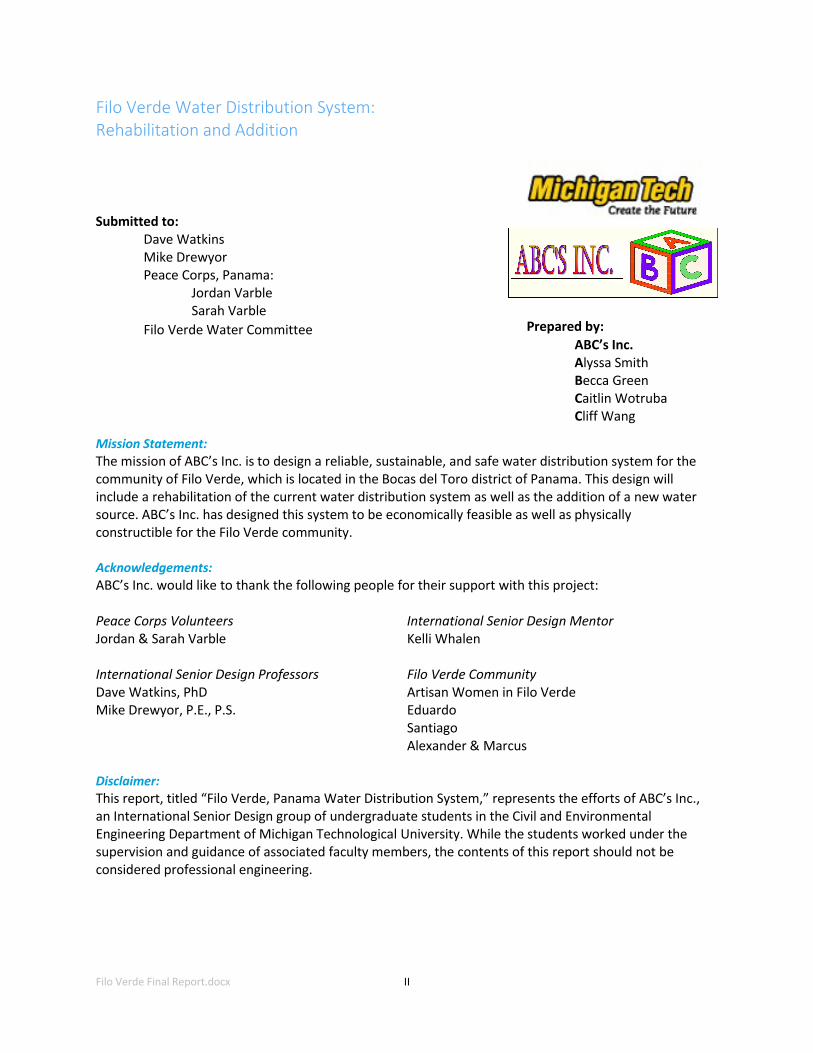
Air blockages can be a problem in long water distribution lines with large elevation changes.
There is enough head above the potential air‐block site in the case of the new Filo Verde water source
that air blockages should not be a problem (see Appendix B). The location of a possible air block, as well
as the elevation profile of the spring source to the community, is shown below in Figure 6.
Figure 6: Profile of New Spring Source to the Community
As Figure 6 displays, there are several smaller river crossings along the path from the new spring
source to the community of Filo Verde. At these points in the system, the piping will need to be elevated
similar to the piping in the current system. The existing system is suspended from tree limbs. Near the
end of the pipeline, there is a major river crossing 92‐feet across Río Caño Sucio with high water
velocities that required further design. A cable-bridge system was chosen as the best design alternative
and is explained further in Section 4.2.5.

Filo Verde Final Report.docx
10
At the end of the system - as mentioned previously and specified by the Peace Corps Volunteers
in Filo Verde - a 600-gallon plastic water tank will serve as a storage tank. This tank will need to be
installed at the same elevation as the reinforced concrete tank in order to include it in the current water
distribution system and ensure the two tanks will not be competing. This will require elevating the plastic
water tank 12‐feet on a wooden platform, as described in Section 4.2.6. The natural ground‐level at the chosen location is 253‐feet, as shown in Figure 11 in Section 4.2.6.
The final part of the Filo Verde water distribution system will be connecting the new tank into
the current 99-tap distribution system. ABC’s Inc. modeled the connection of the new source into the
system at a central point in the community in order to keep the system functioning successfully. The
final location of the connection was based on the results from the water distribution system modeling
software ‐EPANET. These modeled results are discussed in Section 4.2.2.
It was determined from the water quality analysis ABC’s Inc. performed in Filo Verde that the
water needs treatment before household use. In-line treatment is not a realistic system for this
community due to the maintenance required. Instead, in‐home treatment will be recommended. The
methods for in‐home treatment include chlorination and boiling of the water, which are outlined in
Appendix I. The community is currently in the process of learning basic water treatment methods such as
chlorination and boiling. Detailed calculations for the materials that will be used in the Filo Verde water
distribution system can be found in Appendix A.
4.2.1 Current System Tank The tank that will be built as a replacement in the current system is a reinforced concrete
tank. It is designed to be a 13’ x 10’ x 5’ (Length, L x Width, W x Height, H) water storage tank that is 4”
thick. It is separated into two chambers, as mentioned previously in this section. One chamber is 10’ x
10’ x 5’, which serves the majority of the community of Filo Verde. The second chamber, which serves
the houses at a higher elevation in the community, is 3’ x 10’ x 5’ (L x W x H). There will be a 4” thick
shared wall between the two chambers that includes three 2” diameter overflow pipes 6‐inches from
top. The reinforcement required for the tank is as follows: for the walls, No. 6 gage Welded Wire
Fabric (WWF) spaced 4” x 4”; for the roof, a No. 3 rebar grid spaced 6” x 6” should be placed; for the
floor, a No. 3 rebar grid spaced 12”x 12” meets the required properties [3]. A model of the current
system tank that will be built is shown below, with more detailed drawings found in Appendix K.1.
Figure 7: New Tank for the Current System

Filo Verde Final Report.docx
11
4.2.2 EPANET Analysis EPANET is a program that models water distribution systems by simulating pressures in the
piping and was used by ABC’s Inc. for the Filo Verde water distribution system. Entering the elevation of
the taps and outlets, the head at the sources, the tank size and water level, and the pipe sizes, EPANET
will compute the water flow and pressure through the system. By specifying the desired output, the
following can be recorded: the changing in water level in the tanks, the varying demand in each node,
and the velocity and pressure.
EPANET was used to model the water system in Filo Verde. The model included all the taps
in the community, the new and existing source, storage tanks, and pressure break tanks, as
shown in Figure 8 below.
Figure 8: EPANET Schematic
EPANET is also useful for modeling where cut‐off valves will be added to the system, so when
pipes break the community members can repair them more efficiently. The EPANET analysis was
performed with the help of the EPAnet 2 Manual [4], as well as past international senior design
projects [5]. The results of EPANET show that the modeled system with specified demand patterns will
provide sufficient water to the community. The locations of the cut‐off valves and the results of the
EPAnet analysis, as well as a full explanation of the results, can be seen in Appendix J.
4.2.3 Spring Box The purpose of the spring box is to capture the water at the spring source and to cover the

Filo Verde Final Report.docx
12
source so that it is protected from debris and contaminants. The new spring identified is located in the
jungle 1.5‐miles from the community with over a 700-foot elevation change. The spring box, shown
below (more detailed sections can be seen in Appendix K.2), will be used to capture the water and direct
it into the pipeline.
Figure 9: Spring Box for New Source
As shown in the figure, the spring box consists of two wing walls that are four feet long and are
angled toward the small tank that concentrates the water into the system. The location of the spring will
need to be excavated so the source may flow freely. This will also help to remove any excess soil and
contaminants. The spring box will be placed so that it will capture the greatest volume of water from the
spring. There will be a concrete cover over the spring source in order to prevent further contamination
and keep the water as clean as possible since there will not be any in-system treatment.
4.2.4 Pressure Break Tank After performing calculations based on the profile and pressure head between Filo Verde’s
new spring source and the community (Figure 6 in Section 4.2), it was discovered that the pressure would be too great to install an 8,400-foot piping system without bursting the pipes (Appendix B).
Therefore, a pressure break system will need to be installed. There are two viable options for pressure
break tanks in the Filo Verde water distribution system: a masonry tank or a high density polyethylene
(HDPE) tank [6]. ABC’s Inc. recommends the use of the masonry pressure break tank. This tank does
not require screening, as is required for the HDPE system, and the masonry tank is more durable. Also,
the HDPE system still requires the installation of some masonry in addition to the plastic piping, so
building a masonry system appears to be a more efficient option overall.
There will be two pressure‐break tanks along the pipeline from the new spring source to the
community, based on 2” 160 psi 26 SDR PVC piping chosen for the water system. A complete outline of
calculations for this system can be found in Appendix B. Each tank will be 6’ x 4’ x 2’ (L x W x H), and 6”
thick. The tank will be split into two chambers, both the same size (3’ x 4’ x 2’ – L x W x H); there will be
an upper chamber and a lower chamber. The tank will be 1‐foot in the ground with a layer of gravel and

Filo Verde Final Report.docx
13
coarse materials underneath [6]. The upper chamber will have a slightly angled floor towards the lower
chamber so as not to impede the flow of water to the community [6]. The tank will be covered with a
corrugated galvanized sheet (to decrease the weight the community members will have to carry). The
tank will include an inlet pipe from the upstream side of the system that discharges directly downward
onto the well‐plastered floor of the tank (to decrease corrosion). The tank also includes a pipe at the
base of the upper chamber that moves water to the second chamber, where there will be an outlet
pipe that continues moving the water through the piping network to the community. A model of this
tank is shown below, and also can be seen in Appendix K.3 with more details.
Figure 10: Pressure Break Tank
4.2.5 Cable‐tie Crossing The new system includes a few minor stream crossings that are about ten feet wide. The current
water distribution system in the community also has many of these small crossings, so ABC’s Inc. decided
to follow the same method that the community was already using to cross those streams. This method
uses sturdy branches that are cut and placed in the ground to support the pipe over the stream.
The community already understands what is needed and how to build and maintain this method.
The new system will also include a 92-foot crossing over the Río Caño Sucio and will need
support to be able to cross the river and withstand the elements. As stated earlier in the design
alternatives, ABC’s Inc. decided to design the cable crossing because it would be a more cost-effective
method. The land at the river crossing is relatively flat, so a tower and anchor design approach was
taken. This design requires steel towers on each side of the river to elevate the cable and the pipe above
the river, as well as an anchor block 10-feet from the base of each tower. There will be a saddle installed
on top of each tower so that the bending moment would be negligible, and there are stringers that will
connect the main cable to the pipe. The steel towers will be 14-feet long, 4" diameter and placed in
concrete in the ground so that they will not tip over. The pipe should be buried 2 feet, and the concrete
around it should be 1' x 1' x 2' (L x W x Depth) with the pipe placed in the ceneter. The sag of the cable
was designed as 1.75-feet, meaning that the pipeline will be suspended 10.25-feet above the steady-
state water level. A profile of this design can be seen in Figure 11.

Filo Verde Final Report.docx
14
Figure 11: Cable‐Tie Crossing Profile
The anchor blocks will be 3' x 3' x 4.2' (L x W x H) and buried at least 1.5 feet. There will be
welded wire fabric inside the anchor and a rebar stirrup that the main cable will attach to. ABC’s Inc.
was not able to get an exact height for the flood water level in the community because there is
currently no system to record this data, so the value was estimated based on ABC’s Inc.’s observations.
The design of this cable‐tie crossing was based on a design in Field Guide to Environmental Engineering
[7] and used values from geotechdata.info [8]. The detailed calculations for this
system can be seen in Appendix D. 4.2.6 Wooden Platform and New System Tank
An additional tank must be added to connect the new source into the current system. The tank
will be a 600-gallon tank, as specified by the Peace Corps Volunteers in Filo Verde. As mentioned in
Section 4.2, this tank must be placed at the same elevation as the tank in the current system so that
the tanks work together to provide water to the community. The new tank must be elevated to 265-
feet in order to make these tanks work with one another. The ground level at the point where the tank
will be placed is only 253‐feet, and therefore a 12‐foot structure will need to be built to hold the tank
at the elevation required. It is likely that there will be overflow from this tank, because the new spring
source is so abundant. In order to avoid erosion along the slope from the extra water flowing from
the tank, a channel should be built from the overflow pipe at the water tank to the small creek
located at the base of the hill in the community. At the location where the water will be overflowing
from the tank, river rocks must be placed as another measure of erosion control.
This platform was designed using tropical wood because it is the most economical and
accessible structural material available. Tropical wood is also what most of the houses in the
community are comprised of except for the one concrete house in the community and the
concrete school buildings. The wood in this area was assumed to be amarillo wood (terminalia
amazonia) based on location and tree characteristics [9]. The material properties for the wood
were found in Table II-1 in the book Tropical Timbers of the World [10]. The tank is assumed to be
full for all analyses performed. See Appendix C for design details of the structure.
Filo Verde Final Report.docx
15
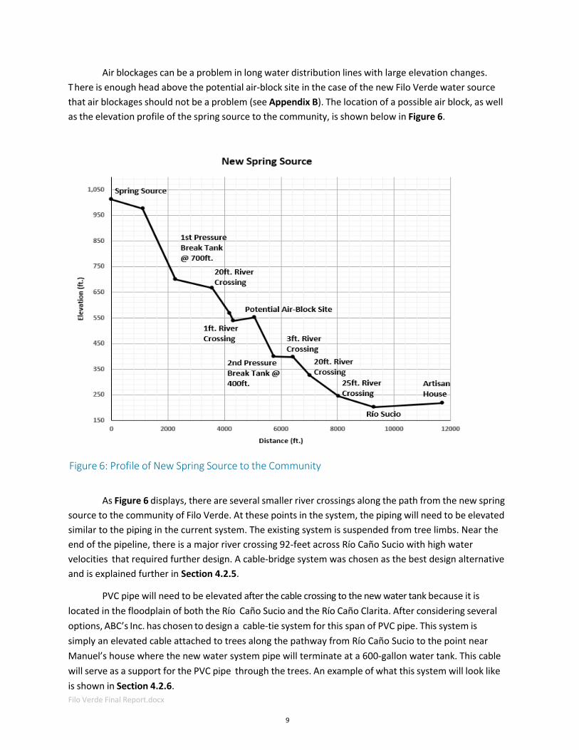
The parameters found were inputted into VisualAnalysis software and analyzed. The structure
was found to be unstable when modeled as four columns without bracing, so bracing will be required in
this structure. This bracing will be cross‐bracing (as is seen in many houses in the community) as modeled
in Appendix K.4. When analyzed in VisualAnalysis, this bracing system was found to be
sufficient for the load of the tank and an assumed wind load of 10 kips (10,000 pounds). This adds an
additional factor of safety into the system by adding such a large load for wind. The platform is assumed
to have a shear or partially‐fixed reaction between the columns and the ground. A fixed‐end reaction can
theoretically be achieved by bolting the columns into 1’ x 1’ x 2’ (L x W x D) concrete pads, as outlined in
Appendix G.
The final design of the wooden platform for the new system’s tank is made up of the following
materials: 52” x 52” x 2” (L x W x H) platform made of six pieces of 52” x 8” x 2” (L x W x thickness, t)
wood at a 0.8” spacing, four 52” x 8” x 2” (L x W x t) pieces of wood used for supports of the platform,
four 4” x 4” x 12’ (L x W x H) columns, and eight pieces of 12.75’ x 4” x 2” (L x W x t) wood used for
bracing of the columns. A sketch of this design is shown below and a more detailed model can be found
in Appendix K.4.
Figure 12: Elevated Wooden Platform

Filo Verde Final Report.docx
16
4.2.7 Alternatives As part of the ABC’s Inc. analysis of the Filo Verde water distribution system, alternative
designs were considered and are explained below. Each alternative considers different parts of the new
system ‐ that are relatively small compared to the whole system, but keeps the main design that
includes a new spring source, PVC piping, pressure break tanks, a river crossing, a new tank for the
current system, and an elevated wooden platform for the plastic water tank.
The first alternative was the support design at the crossing of the water system over the Río
Caño Sucio. The pipeline will need to be supported in order to cross the 92-foot span of the river. ABC’s
Inc. considered two alternative designs for this crossing. The first was to design a cable‐tie crossing; this
design would require a tower on each side of the river to hold the main cable high enough over the high
water level. The main cable would have smaller cables, stringers, which would hang down and wrap
around the PVC pipe to support the pipeline. The second alternative used a steel pipe, with the 2” PVC
pipe inside, to provide the support over the river. This design also requires a tower to keep the pipe
above the high water level but would also include protection for the PVC pipe from most damage.
ABC’s Inc. considered several factors when determining which alternative to design. Two factors were
cost and constructability, both of which were constraints mentioned in Section 4.1. The steel pipe
would be more expensive than the cables and it would be easier to carry the cables the 2.5‐mile hike
into the village, so ABC’s Inc. decided to design a cable‐tie crossing. This crossing is discussed in more
detail in Section 4.2.5.
The second alternative was whether or not to cover the 2” PVC pipe with a larger PVC pipe as it is
strung in the trees after the river crossing to the tank. After the pipeline crosses the Río Caño Sucio, it
will need to remain elevated due to this area being a floodplain. Covering the 2” PVC pipe with a 2.5” PVC
pipe would help to protect the pipe from the UV (sun) and from objects like branches or coconuts
that may fall on the pipe and break it. The extra pipe would also add to the cost of the system, but ABC’s
Inc. determined that the extra protection for the pipe would be worth the cost.
The last alternative that ABC’s Inc. deliberated was whether or not to leave the system from the
new spring source separate from the current system. Not connecting the two systems would mean that
there would only be pipe needed between the spring box and the tank. It is typically the individual
community member’s responsibility to add in their own personal tap if they would like one at their
house. This alternative required one tap placed at the tank itself, where community members would be
able to get water from the tank if they did not want to place a tap at their house. This alternative is
much less expensive than connecting the systems since there is no need for the pipe from the tank to
connect into the current system and also because the tank would not need to be elevated. The
constraints that were given state that the two systems should be connected so that the entire
community can have more reliable water. Therefore, not connecting the systems would violate one of
the constraints of the project so ABC’s Inc. did not choose this alternative, though it could still be
considered if funding is short.

Filo Verde Final Report.docx
17
5.0 Construction/Maintenance Manual, Cost Estimate and Schedule
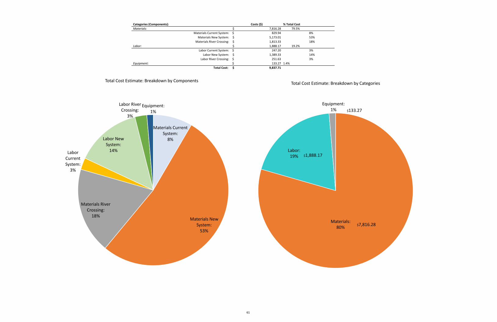
The system’s total cost was found to be $9,840, which includes: 79.5-percent material
costs, 19.2-percent labor costs, and 1.4-percent cost of equipment. The total cost of the system is
broken down in the Figure 13 and more detail can be found in Appendix F. The community’s
contribution to this project will be the labor costs, which totals to nearly $2,000 of the project. This
means that the government funds needed for materials and equipment will be $7,950.
Figure 13: Water Distribution System Cost Estimate
A schedule was created for the water distribution systems based off of the cost estimate. ABC’s
Inc. estimated actual working time for the system within the cost estimate based on productivity
estimates from Filo Verde’s PCVs. However, the new spring source is located over 1.5‐miles away from
the community, so ABC’s Inc. increased the time allotted for each of the tasks in the final schedule to
allow for travel time. The total time estimated for these tasks in the cost estimate was 34 days, while
the final schedule found that 52 days of work would be sufficient for the completion of this design.
The final schedule, including travel time to the new water distribution line sites, can be found in
Appendix H.
In addition, a construction and maintenance manual has been created for the Filo Verde water
distribution system and can be found in Appendix G. This manual includes installation procedures for
each element of the system, such as the PVC piping and cable‐tie crossing, as well as detailed measures
for mixing concrete.
Materials Current System:
8%
Materials New System:53%
Materials River Crossing:18%
Labor Current System:3%
Labor New System:14%
Labor River Crossing:3%
Equipment:1%
Total Cost Estimate: Breakdown by Components

Filo Verde Final Report.docx
18
6.0 Conclusion
The goal of ABC’s Inc. was to design a reliable and safe water distribution system for the
community of Filo Verde. ABC’s Inc. visited the Filo Verde community for a week in August 2014 to
gather all the necessary data. Then, ABC’s Inc. worked throughout the semester at Michigan Tech to
design the system that was described above. In order to accomplish this task, the current system
needed to be rehabilitated and a new system needed to be created that connects with the current
system.
ABC’s Inc. has put together a design that will meet all the needs of the community. The current
water distribution system has lasted twenty years but needs to be updated. ABC’s Inc. has designed a
new tank for the system and also specified locations for cutoff valves to be placed. The current system
alone is not meeting all of the needs of the community in Filo Verde, so a new spring source is needed.
ABC’s Inc. has mapped out a route for a water distribution system along a newly‐ discovered spring
source in order to bring this water into the community. Within this new system, ABC’s Inc. designed a
spring box, pressure break tanks, a river crossing over the Río Caño Sucio, a platform for the new
system’s tank, and a connection into the current system. The total estimated cost of this system is
nearly $10,000 ($9,840), including labor. Based on production rates from the PVCs as well as travel
time, this design will require 52 days to construct.
One constraint given by the PCVs was to include a treatment method in the system. ABC’s Inc.
did not include an in‐line treatment method for the water quality (also per PCV’s request) but will
recommend in‐home treatment such as chlorination or boiling. In addition, a construction and
maintenance manual is provided for the community to reference as needed for the design so that the
system will remain sustainable. A key concern for the system’s sustainability is that maintenance will
not be performed on the system, which has been a problem for PCVs in the past. This is a key concern
because it could negate the additional reliability provided by the new spring source. ABC’s Inc.
believes that the maintenance and construction manual included will help to lessen this concern
through educating the community on the proper way to construct and maintain the system. Another
sustainability concern involves the PVC piping. In the current system, there are many exposed PVC
pipes, which leads to more breakages and increased problems with UV radiation. The proper way to
bury piping has been outlined in the construction and maintenance manual.

Filo Verde Final Report.docx
19
7.0 References
[1] Varble, Jordan and Varble, Sarah. Community Analysis and Development Plan: Filo Verde. United
States Peace Corps. February 2014.
[2] "PVC Pipe‐SDR Series." PVC Pipe SDR Series Specifications. N.p., n.d. Web. 20 Oct. 2014. Table: SDR
26 ‐ W.P. 160 PSI. <http://www.harvel.com/technical‐support‐center/product‐
specifications/pvc‐pipe‐sdr‐series>
[3] ACI. Building Code Requirements for Reinforced Concrete. American Concrete Institute, code 318‐83.
Web. October 20 2014. http://www.ncsta.net/Rebar.pdf
[4] Rossman, Lewis A. EPANET 2 Manual. United States Environmental Protection Agency. September
2000. Web. 20 Oct. 2014. <http://nepis.epa.gov/Adobe/PDF/P1007WWU.pdf>
[5] Watkins, David. iDesign: CEE International Senior Design (2009‐2013). Web. 3 Nov. 2014.
<http://www.cee.mtu.edu/~dwatkins/idesign09.htm>
[6] Jordan, Thomas. Handbook of Gravity‐Flow Water Systems. Kathmandu, Nepal: United Nations
Children’s Fund, 1980. Print.
[7] Stone, Lyle J. "Chapter 13: Pipeline Crossings." Field Guide to Environmental Engineering. ASCE Press. 241‐265. Print.
[8] "Soil Friction Angle." Angle of Friction. N.p., 14 Dec. 2013. Web. 29 Oct. 2014.
<http://www.geotechdata.info/parameter/angle‐of‐friction.html>. Organic Clay for High
Plasticity
[9] Planting Empowerment. Tropical Woods. 2014. Web. 13 October 2014.
<http://www.plantingempowerment.com/tropical‐woods/>
[10] Chudnoff, Martin. Tropical Timbers of the World. United States Department of Agriculture. April
1980. Web. 13 October 2014.
<http://www.esf.edu/scme/wus/documents/TropicalTimbersoftheWorld‐chud_total.pdf>
[11] Demand Media, Inc. eHow: How to Install a Shutoff Valve to a PVC Pipe. April 2014. Web. 15
November 2014. <http://www.ehow.com/how_7899701_install‐shutoff‐valve‐pvc‐pipe.html>

Filo Verde Final Report.docx
20
8.0 Appendices


Filo Verde Final Report.docx
21
Appendix A ‐ Material Calculations
12/12/2014 Material Calculations iDesignABC's Inc. Alyssa Smith
Material calculations
Constants:
≔γc 150
Finding weights of materials:http://www.engineeringtoolbox.com/concrete-sand-cement-gravel-mixtures-d_1547.html
1 lb cement : 2 lb sand : 3 lb gravel
≔γcement 94 ――3
≔γsand 110 ――3
≔γgravel 120 ――3
≔Parts =++1 2 3 6
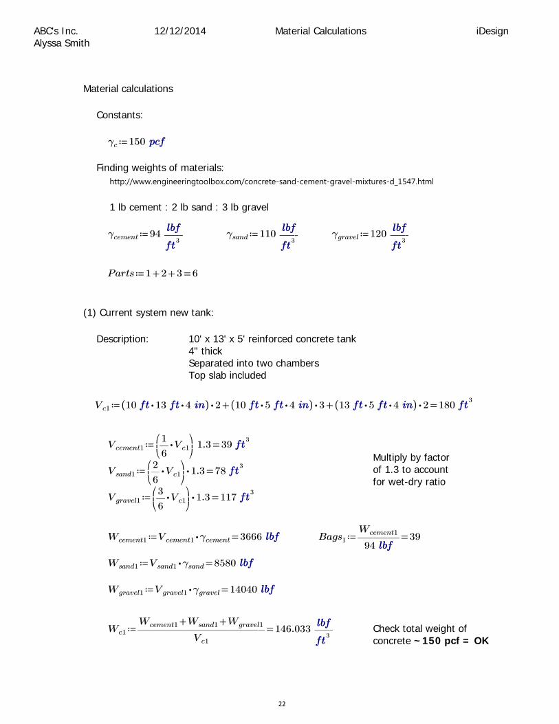
(1) Current system new tank:
Description: 10' x 13' x 5' reinforced concrete tank 4" thickSeparated into two chambersTop slab included
≔Vc1 =++⋅(( ⋅⋅10 13 4 )) 2 ⋅(( ⋅⋅10 5 4 )) 3 ⋅(( ⋅⋅13 5 4 )) 2 1803
≔Vcement1 =⎛⎜⎝
⋅―1
6Vc1
⎞⎟⎠
1.3 393
≔Vsand1 =⋅⎛⎜⎝
⋅―2
6Vc1
⎞⎟⎠
1.3 783
Multiply by factor of 1.3 to account for wet-dry ratio
≔Vgravel1 =⋅⎛⎜⎝
⋅―3
6Vc1
⎞⎟⎠
1.3 1173
≔Wcement1 =⋅Vcement1 γcement 3666 ≔Bags1 =―――Wcement1
9439
≔Wsand1 =⋅Vsand1 γsand 8580
≔Wgravel1 =⋅Vgravel1 γgravel 14040
≔Wc1 =―――――――――++Wcement1 Wsand1 Wgravel1
Vc1
146.033 ――3
Check total weight of concrete ~150 pcf = OK
22

12/12/2014 Material Calculations iDesignABC's Inc. Alyssa Smith
(2) New Source New Spring Box:
Description: 3' x 10' x 6" 'wall' into a 4' x 4' x 4" chamber4" thickTarp put on top of structure to reduce natural pollution
≔Vwall =⋅⋅3 10 6 153
≔Vchamber =⋅⋅⋅5 4 4 4 26.73 Chamber is open to wall on
one side, therefore x5, not x6≔Vc2 =+Vwall Vchamber 41.73
≔Vcement2 =⎛⎜⎝
⋅―1
6Vc2
⎞⎟⎠
1.3 9.0283
Multiply by factor of 1.3 to account for wet-dry ratio
≔Vsand2 =⋅⎛⎜⎝
⋅―2
6Vc2
⎞⎟⎠
1.3 18.0563
≔Vgravel2 =⋅⎛⎜⎝
⋅―3
6Vc2
⎞⎟⎠
1.3 27.0833
≔Wcement2 =⋅Vcement2 γcement 848.611 ≔Bags2 =―――Wcement2
949.028
≔Wsand2 =⋅Vsand2 γsand 1986.111
≔Wgravel2 =⋅Vgravel2 γgravel 3250
(3) New Source Pressure Break Tank:
Description: 2 tanks - 6' x 4' x 2' each4" thick
≔Vc3 =⋅⋅2 (( ++⋅⋅2 6 2 ⋅⋅2 4 2 ⋅⋅2 6 4 )) 4 58.73
≔Vcement3 =⎛⎜⎝
⋅―1
6Vc3
⎞⎟⎠
1.3 12.7113
Multiply by factor of 1.3 to account for wet-dry ratio
≔Vsand3 =⋅⎛⎜⎝
⋅―2
6Vc3
⎞⎟⎠
1.3 25.4223
≔Vgravel3 =⋅⎛⎜⎝
⋅―3
6Vc3
⎞⎟⎠
1.3 38.1333
≔Wcement3 =⋅Vcement3 γcement 1194.844 ≔Bags3 =―――Wcement3
9412.711
≔Wsand3 =⋅Vsand3 γsand 2796.444
≔Wgravel3 =⋅Vgravel3 γgravel 4576
23

12/12/2014 Material Calculations iDesignABC's Inc. Alyssa Smith
(4) Anchors for River Crossing
Description: Two blocks 3' x 3' x 4.25' (L x W x H)
≔Vc4 =⋅2 (( ⋅⋅3 3 4.25 )) 76.53
≔Vcement4 =⎛⎜⎝
⋅―1
6Vc4
⎞⎟⎠
1.3 16.5753
Multiply by factor of 1.3 to account for wet-dry ratio
≔Vsand4 =⋅⎛⎜⎝
⋅―2
6Vc4
⎞⎟⎠
1.3 33.153
≔Vgravel4 =⋅⎛⎜⎝
⋅―3
6Vc4
⎞⎟⎠
1.3 49.7253
≔Wcement4 =⋅Vcement4 γcement 1558.05 ≔Bags4 =―――Wcement4
9416.575
≔Wsand4 =⋅Vsand4 γsand 3646.5
≔Wgravel4 =⋅Vgravel4 γgravel 5967
(5) Anchor for Platform:
Description: 6" of concrete around base of wooden platform (in the ground)
≔Vc5 =⋅4 ⎛⎝ ⋅4 ⎛⎝ −1002
162 ⎞⎠⎞⎠ 9.3
3
≔Vcement5 =⎛⎜⎝
⋅―1
6Vc5
⎞⎟⎠
1.3 2.0223
Multiply by factor of 1.3 to account for wet-dry ratio
≔Vsand5 =⋅⎛⎜⎝
⋅―2
6Vc5
⎞⎟⎠
1.3 4.0443
≔Vgravel5 =⋅⎛⎜⎝
⋅―3
6Vc5
⎞⎟⎠
1.3 6.0673
≔Wcement5 =⋅Vcement5 γcement 190.089 ≔Bags5 =―――Wcement5
942.022
≔Wsand5 =⋅Vsand5 γsand 444.889
≔Wgravel5 =⋅Vgravel5 γgravel 728
24
12/12/2014 Material Calculations iDesignABC's Inc. Alyssa Smith
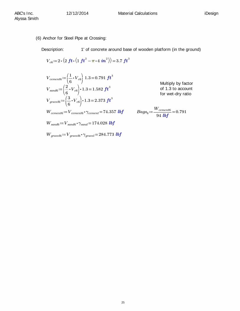
(6) Anchor for Steel Pipe at Crossing:
Description: 1' of concrete around base of wooden platform (in the ground)
≔Vc6 =⋅2 ⎛⎝ ⋅2 ⎛⎝ −12
⋅ 42 ⎞⎠⎞⎠ 3.7
3
≔Vcement6 =⎛⎜⎝
⋅―1
6Vc6
⎞⎟⎠
1.3 0.7913
Multiply by factor of 1.3 to account for wet-dry ratio
≔Vsand6 =⋅⎛⎜⎝
⋅―2
6Vc6
⎞⎟⎠
1.3 1.5823
≔Vgravel6 =⋅⎛⎜⎝
⋅―3
6Vc6
⎞⎟⎠
1.3 2.3733
≔Wcement6 =⋅Vcement6 γcement 74.357 ≔Bags6 =―――Wcement6
940.791
≔Wsand6 =⋅Vsand6 γsand 174.028
≔Wgravel6 =⋅Vgravel6 γgravel 284.773
25

12/12/2014 Material Calculations iDesignABC's Inc. Alyssa Smith
Summary of Material Calculations
Total - Current System:
≔Wcementcurrent =Wcement1 3666
≔Bagscementcurrent =Bags1 39 39 bags required
≔Wsandcurrent =Wsand1 8580
≔Vsandcurrent =Vsand1 783
≔Wgravelcurrent =Wgravel1 14040
≔Vgravelcurrent =Vgravel1 1173
≔Vconcretecurrent =Vc1 1803
Total - New System:
≔Wcementnew =+++Wcement2 Wcement3 Wcement4 Wcement5 3791.6
≔Bagscementnew ++++Bags2 Bags3 Bags4 Bags5 Bags6
=Bagscementnew 41.127 42 bags required
≔Wsandnew =+++Wsand2 Wsand3 Wsand4 Wsand5 8873.9
≔Vsandnew =++++Vsand2 Vsand3 Vsand4 Vsand5 Vsand6 82.2543
≔Wgravelnew =+++Wgravel2 Wgravel3 Wgravel4 Wgravel5 14521
≔Vgravelnew =++++Vgravel2 Vgravel3 Vgravel4 Vgravel5 Vgravel6 123.3813
≔Vconcretenew =++++Vc2 Vc3 Vc4 Vc5 Vc6 189.8183
26

Appendix B ‐ Pressure Break Tank Calculations
Filo Verde Final Report.docx
27

A sss sss ssss ss ssssss December 12 4444aassa sa s
sss sss ssss ss ssssss
sss s4ss sss ss sss s s s s 444 s s s s sass sas sss s s ssss s as a as ass sas sas saas ssa ss s sssssa sass s ss sss 4ssss ss s ss assss ss ss s e sss 4s ss s s s ss ss 4ssss sas s s
r ss ss as s ssss
�✁✂ ✄☎✆✝ ✞✟✠
sss ssss ss sa
�✡☛☞✌✍✎✏ ✑✒✑✓ ✠✔
�✡✕ ✖✗✗ ✠✔ �✘☛✕ ✑✑✑✑ ✠✔
�✡✙ ✄✄✗ ✠✔ �✘✕✙ ✑☎✖☎ ✠✔
�✡✚ ✛✄✗ ✠✔ �✘✙✚ ✄✑✓ ✠✔
�✡✜ ✛✓✖ ✠✔ �✘✚✜ ✑✓✛ ✠✔
�✡✢ ✛✛☎ ✠✔ �✘✜✢ ✗✛✛ ✠✔
�✡✣ ✓✖✗ ✠✔ �✘✢✣ ✄✗✄ ✠✔
�✡✤ ✓☎✛ ✠✔ �✘✣✤ ✄✒✒ ✠✔
�✡✥ ☎✝✝ ✠✔ �✘✤✥ ✑✒☎✛ ✠✔
�✡✦ ☎✒☎ ✠✔ �✘✥✦ ✑☎✝✗ ✠✔
�✡✕✧ ☎✄✛ ✠✔ �✘✦✕✧ ✑✒✒✒ ✠✔
:ss ss s :
�★✩✕ ✪✫✡☛☞✌✍✎✏ ✡✕ ✓✄ ✠✔
�★✩✙ ✪✫✡☛☞✌✍✎✏ ✡✙ ✓✝✄ ✠✔
�★✩✚ ✪✫✡☛☞✌✍✎✏ ✡✚ ✝✝✄ ✠✔
�★✩✜ ✪✫✡☛☞✌✍✎✏ ✡✜ ✝✗✝ ✠✔
�★✩✢ ✪✫✡☛☞✌✍✎✏ ✡✢ ✝✄✑ ✠✔
�★✩✣ ✪✫✡☛☞✌✍✎✏ ✡✣ ✄✑✄ ✠✔
�★✩✤ ✪✫✡☛☞✌✍✎✏ ✡✤ ✄✬✬ ✠✔
�★✩✥ ✪✫✡☛☞✌✍✎✏ ✡✥ ✗✄✖ ✠✔
�★✩✦ ✪✫✡☛☞✌✍✎✏ ✡✦ ✬✑✑ ✠✔
�★✩✕✧ ✪✫✡☛☞✌✍✎✏ ✡✕✧ ✗✝✬ ✠✔
sss sss :
�✭✮ ✑✆☎
�✯✰✱✰✏ ✪✲✲✲✑✄✒ ✞✳✴
✭✮✑✓✓✆✓✓✓ ✞✳✴
28

A s sss sss ssss ss ssssss December 12 4444aassa sa s
�✯✕ ✪✵★✩✕ ✁✂ ✑✛✆✄ ✞✳✴ KK
�✯✙ ✪✵★✩✙ ✁✂ ✑✝✖✆✖✓✓ ✞✳✴ KK - t tt t t tt t t
�✡✰✶✕ ✗✒✒ ✠✔
ss s ss s ss sss 4ssss ss s ss s sss ssss s 44 s y 44 s 4sss sas sss s
ys ass ss s :
�★✩✚ ✪✫✡✰✶✕ ✡✚ ✑✓✓ ✠✔
�★✩✜ ✪✫✡✰✶✕ ✡✜ ✑✄✑ ✠✔
�★✩✢ ✪✫✡✰✶✕ ✡✢ ✑✝✬ ✠✔
�★✩✣ ✪✫✡✰✶✕ ✡✣ ✓✒✓ ✠✔
�★✩✤ ✪✫✡✰✶✕ ✡✤ ✓✗✛ ✠✔
�★✩✥ ✪✫✡✰✶✕ ✡✥ ✝✛✄ ✠✔
�★✩✦ ✪✫✡✰✶✕ ✡✦ ✝✖✬ ✠✔
�★✩✕✧ ✪✫✡✰✶✕ ✡✕✧ ✝✓✛ ✠✔
sss sss :
�✯✚ ✪✵★✩✚ ✁✂ ✛✗✆✄✓✓ ✞✳✴ KK
�✯✜ ✪✵★✩✜ ✁✂ ✄✖✆✗✄✗ ✞✳✴ KK
�✯✢ ✪✵★✩✢ ✁✂ ✄✝✆✑✓✓ ✞✳✴ KK
�✯✢ ✪✵★✩✢ ✁✂ ✄✝✆✑✓✓ ✞✳✴ KK
�✯✣ ✪✵★✩✣ ✁✂ ✑✓✑✆✓ ✞✳✴ KK
�✯✤ ✪✵★✩✤ ✁✂ ✑✄☎✆✛ ✞✳✴ KK - t tt t t tt t t
�✡✰✶✙ ✝✒✒ ✠✔
ss s s s ss sss 4ssss ss s ss s sss ssss s 444 s y 44 s 4sss sas ss sss ss s
ys ass ss s :
�★✩✣ ✪✫✡✰✶✙ ✡✣ ✓ ✠✔
�★✩✤ ✪✫✡✰✶✙ ✡✤ ✗✛ ✠✔
�★✩✥ ✪✫✡✰✶✙ ✡✥ ✑✛✄ ✠✔
�★✩✦ ✪✫✡✰✶✙ ✡✦ ✑✖✬ ✠✔
�★✩✕✧ ✪✫✡✰✶✙ ✡✕✧ ✑✓✛ ✠✔
29

A sss sss ssss ss ssssss December 12 4444aassa sa s
sss sss :
�✯✣ ✪✵★✩✣ ✁✂ ✑✆✓ ✞✳✴ KK
�✯✤ ✪✵★✩✤ ✁✂ ✓☎✆✛ ✞✳✴ KK
�✯✥ ✪✵★✩✥ ✁✂ ✄✗✆✄ ✞✳✴ KK
�✯✦ ✪✵★✩✦ ✁✂ ✬✛✆✬ ✞✳✴ KK
�✯✕✧ ✪✵★✩✕✧ ✁✂ ✛✬✆✛ ✞✳✴ KK
ss s sss ssss ss s sssss ssa sssssss s sasss sss s s sss s s ssa s 4 4 s s s s ss ss ss ss sssss asss ss s ss s ss sss 4ssss ss s s ss ss ss s sss sas s s ssss sss ss 4s s ss s s sas s sssasa sss s ss ssasss s ss sas
e e ee e e ee t tee tte ee e e -t tt t t t e t e e e - t t t t t e tt e t
e et ou e e t t t t e tt
. .
30

A sss sss ssss ss ssssss December 12. 4444aassa sa s
sssssssssssssssssssssssssss
r ss rssras sr rssss
�✁✂ ✄☎✆✝ ✞✟✠
ssssssss
�✡☛☞✌✍✎✏ ✑✒✑✓ ✠✔
�✡✕ ✖✓✗ ✠✔
�✡✘ ✖✖☎ ✠✔
�✡✙ ☎✒☎ ✠✔
�✡✚✛✜✢ ☎✄✖ ✠✔
ss rsa
�✣☛✕ ✓✑✖✑ ✠✔
�✣✕✘ ✤✖✖ ✠✔
�✣✘✙ ✓✖✝✤ ✠✔
�✣✙✚ ✑✒✒✒ ✠✔
ws sasa rssr
�✥ ✒✆✑ ✦✣
✧
sa:ss s: sss :ss sss s sss 4ss s:
�★✩ ✪✫✡☛☞✌✍✎✏ ✡✘ ✝✄✑ ✠✔
�✬✕ ✪✭✁✂ ★✩ ✑✗✗✆✤✄✤ ✞✧✮
�✬✛✚✯ ✪✑ ✰✔✱ ✑✝✆✄✗✄ ✞✧✮
�✣✲✕ ✪✭✣☛✕
✳
✴✵✦✦✦
✬✕
✶✬✕ ✬✛✚✯
✷
✸✹
✳✵ ✭☎✆✗✓✖ ✑✒✺ ✷✹ ✠✔
�✰✻✼✽✾ ✪✿❀✿❁✳
✴✵✦✦✦✫✡✘ ✡✙
✣✘✙
✷
✸✹
✖✆✄✓✖ ❂
�✡✲✕ ✪✫✡✘ ✭✣✲✕ ❃❄❁ ❅❅✰✻✼✽✾❆❆ ☎✄✓✆✤❇✑ ✠✔
�✬✲✕ ✪✭✁✂ ✳✵ ✫✡☛☞✌✍✎✏ ✡✲✕✷✹ ✓☎✝✆✄✄☎ ✞✧✮
s:ssssss s ass::
�★✏ ✪✦✦✦✦✫✬✲✕ ✬✛✚✯
✁✂
✤✑✖✆✓✒✖ ✠✔
31

A sss sss ssss ss ssssss December 12 4444aassa sa s
:ssss ass::
�✠ ✒✆✒✑✖
�✣ ✪✶✶✶✣☛✕ ✣✕✘ ✣✘✙ ✣✙✚✳✵ ✭❇✆✝✖✓ ✑✒
✺ ✷✹ ✠✔
�❈ ☎ ✮✻
�❉ ✑ ✦✠✔
✧
�✼ ✓☎✆☎ ✦✠✔
✧❊
�❋✯●✜☞✍ ✒✆✖ ✠✔
�❋✩ ✪✶✭✠✳
✴✵✦✣
❈
✷
✸✹✦✦❉❊
☎ ✼❋✯●✜☞✍ ✑☎✆✓✑✓ ✠✔
�★❍ ✪✫★✏ ❋✩ ✤✒☎✆✗✗☎ ✠✔
�★❍●✜✛■ ✪✶★❍ ✡✲✕ ✗✄✄✆✤✤✓ ✠✔ > ✪✡✚✛✜✢ ☎✄✖ ✠✔
❏ mmsmsssssmsssmsssmsssssssssmsssssssmsss
32

AB sss sss ssss ss ssssss December 12 4444aassa sa s
:rs :ss sss 4ssss ss s rsss 4s s::s: y s s ss s ssssssss sr 44 rs s : s s ss s ssssssss sr 444rs :as rssssrs r s ssa s as s sass sas a ssa rsss ssss ssass s srrs ss: 4a sss 4ss ssrs s sas :s:s r a ssa
sa:ss s: sss :ss sss s sss 4ss s :srsss rss s :ss sss 4ssss ss s::
�★✩ ✪✫✤✒✒ ✠✔ ✡✘ ✑✝❇ ✠✔
�✬✕ ✪✭✁✂ ★✩ ✄✝✆✑✓✓ ✞✧✮
�✬✛✚✯ ✪✑ ✰✔✱ ✑✝✆✄✗✄ ✞✧✮
�✣✲✕ ✪✭✣☛✕
✳
✴✵✦✦✦
✬✕
✶✬✕ ✬✛✚✯
✷
✸✹
✳✵ ✭☎✆✖✄✝ ✑✒✺ ✷✹ ✠✔
�✰✻✼✽✾ ✪✿❀✿❁✳
✴✵✦✦✦
✫✡✘ ✡✙
✣✘✙
✷
✸✹
✖✆✄✓✖ ❂
�✡✲✕ ✪✫✡✘ ✭✣✲✕ ❃❄❁ ❅❅✰✻✼✽✾❆❆ ✓✒✒✆☎✄✓ ✠✔
�✬✲✕ ✪✭✁✂ ✳✵ ✫✤✒✒ ✠✔ ✡✲✕✷✹ ✑✤✓✆☎✑✗ ✞✧✮
s:ssssss s ass::
�★✏ ✪✦✦✦✦✫✬✲✕ ✬✛✚✯
✁✂
✓✄✖✆❇☎✓ ✠✔
:ssss ass::
�✠ ✒✆✒✑✖
�✣ ✪✶✶✣✕✘ ✣✘✙ ✣✙✚✳✵ ✭✖✆✓✒☎ ✑✒
✺ ✷✹ ✠✔
�❈ ☎ ✮✻
�❉ ✑ ✦✠✔
✧
�✼ ✓☎✆☎ ✦✠✔
✧❊
�❋✯●✜☞✍ ✒✆✖ ✠✔
�❋✩ ✪✶✭✠✳
✴✵✦✣
❈
✷
✸✹✦✦❉❊
☎ ✼❋✯●✜☞✍ ✤✆✗✑ ✠✔
33

A sss sss ssss ss ssssss December 12 4444aassa sa s
�★❍ ✪✫★✏ ❋✩ ✓✖✤✆✗✑✝ ✠✔
�★❍●✜✛■ ✪✶★❍ ✡✲✕ ✄✖❇✆✑✤✤ ✠✔ > ✪✡✚✛✜✢ ☎✄✖ ✠✔
❏ mmsmsssssmsssmsssmsssssssssmsssssssmsss
sa:ss s: sss :ss sss s sss 4ss s :srsss s s : :ss sss 4ssss ss s::
�★✩ ✪✫✝✒✒ ✠✔ ✡✙ ✑✗❇ ✠✔
�✬✕ ✪✭✁✂ ★✩ ❇✖✆❇ ✞✧✮
�✬✛✚✯ ✪✑ ✰✔✱ ✑✝✆✄✗✄ ✞✧✮
�✣✲✕ ✪✭✣☛✕
✳
✴✵✦✦✦
✬✕
✶✬✕ ✬✛✚✯
✷
✸✹
✳✵ ✭☎✆✄✗ ✑✒✺ ✷✹ ✠✔
�✰✻✼✽✾ ✪✿❀✿❁✳
✴✵✦✦✦
✫✡✘ ✡✙
✣✘✙
✷
✸✹
✖✆✄✓✖ ❂
�✡✲✕ ✪✫✡✘ ✭✣✲✕ ❃❄❁ ❅❅✰✻✼✽✾❆❆ ☎❇✤✆❇☎✄ ✠✔
�✬✲✕ ✪✭✁✂ ✳✵ ✫✝✒✒ ✠✔ ✡✲✕✷✹ ✝❇✆✄✒✗ ✞✧✮
s:ssssss s ass::
�★✏ ✪✦✦✦✦✫✬✲✕ ✬✛✚✯
✁✂
✤❇✆☎✄ ✠✔
:ssss ass::
�✠ ✒✆✒✑✖
�✣ ✪✶✶✣✕✘ ✣✘✙ ✣✙✚✳✵ ✭✖✆✓✒☎ ✑✒
✺ ✷✹ ✠✔
�❈ ☎ ✮✻
�❉ ✑ ✦✠✔
✧
34

A sss sss ssss ss ssssss December 12 4444aassa sa s
�✼ ✓☎✆☎ ✦✠✔
✧❊
�❋✯●✜☞✍ ✒✆✖ ✠✔
�❋✩ ✪✶✭✠✳
✴✵✦✣
❈
✷
✸✹✦✦❉❊
☎ ✼❋✯●✜☞✍ ✤✆✗✑ ✠✔
�★❍ ✪✫★✏ ❋✩ ✤✒✆✓✖✑ ✠✔
�★❍●✜✛■ ✪✶★❍ ✡✲✕ ✓✖❇✆✑✤✤ ✠✔ > ✪✡✚✛✜✢ ☎✄✖ ✠✔
❏ mmsmsssssmsssmsssmsssssssssmsssssssmsss
35


Appendix C ‐ Wooden Platform Calculations
Filo Verde Final Report.docx
36

A 42/1244444 sssss ssss ssss ss ssssss sns sn sh s shssh
sssss :s : ssss ssss:
�✁✂ ✄☎✆✝ ✞✟✠
�✡☛☞✌✍ ✎✄✏✏ ✑✒✓ ✔✏✆☎ ✠✕✖
�✗☛☞✌✍ ✝✄ ✘✙
�✚☛☞✌✍ ✛✜ ✘✙
�✢☛☞✌✍ ✜✣✏ ✓✤✠
�✢✂☞☛✥✦ ✎✧✁✂ ✡☛☞✌✍ ★✏✏★ ✓✤✠
�✢☛☞✌✍☛✩☛☞✪ ✎✫✢☛☞✌✍ ✢✂☞☛✥✦ ★✜✣★ ✓✤✠
assasssss sa :ssas ss ssss: :sshs ssss shsas ss
�✬✕✭✮✙✑✕✯✰✥✌✱✲✌✳ ✜✴✏✏✏ ✞✵✘
�✬✕✘✠✠✙✮✵✵ ☎✄✏✏ ✶✵✘
nsssessssh e essh nsssess
)hssa:44))) s a sss4 hs4)s 4ss shs s 4:ssas ss:shess sashssssss) hss)sssss asa)
:sh 4dd d dd d 4d )d d s d s) ass s sa )sss
d ass s )ssss es ssdsssss
�✷✸✲✥✹✥ ✝✔ ✘✙
�✢✸✲✥✹✥ ✔ ✘✙
�✕✸✲✥✹✥ ☎ ✘✙
�✢✸✥✦✸✲✥✹✥ ✎✺✺✺✢☛☞✌✍☛✩☛☞✪
✄✔★★✆✔ ✓✤✠
�✻✼ ✎✺✺✺✢✸✥✦✸✲✥✹✥
✝✔ ✘✙☎✜✣✆✛★✔ ✞✓✠
sss s sss s ssh s ss sss ass shassss ss sss sa sss sssss s ssh s assasshss s asssassh es ss s ns s ssss ssss
37

38
12/12/2014 Wooden Platform VisualAnalysis Results iDesign ABC’s Inc. Alyssa Smith
Figure 1: Wooden Platform Loads Figure 2: Wooden Platform Analysis Results

39
ABC’s Inc. 12/12/2014 Wooden Platform VisualAnalysis Results iDesign Alyssa Smith
Wooden Platform VisualAnalysis 4.00.EDU Report Company: Michigan Technological University Only
Engineer: Alyssa Smith Billing: For Educational Purposes
File: \\homedir.mtu.edu\home\Desktop\Classes\Fall 2014\iDesign\Wooden Platform.vap
Load Cases —————————————————————————————————————————————————— Load Case Strength Service Results —————————————————————————————————————————————————— ( 1)Service Case 1 No No 1st Ord ——————————————————————————————————————————————————
4.3 Statics Check ————————————————————————————————————————————————————————————— Load Case L.FX L.FY L.MZ R.FX R.FY R.MZ
K K K-ft K K K-ft ————————————————————————————————————————————————————————————— Service Case 1 10.00 -0.82 -121 -10.0 0.82 121.6 —————————————————————————————————————————————————————————————
4.4 Nodal Displacements ————————————————————————————————————————————————— Node Load Case DX DY RZ
in in deg ————————————————————————————————————————————————— N1 Service Case 1 0.00 0.00 0.00 N2 ” 0.00 0.00 0.00N3 ” 0.34 0.05 -0.26 N4 ” 0.33 -0.05 -0.05 —————————————————————————————————————————————————
4.5 Nodal Reactions ————————————————————————————————————————————————— Node Load Case FX FY MZ
K K K-ft ————————————————————————————————————————————————— N1 Service Case 1 -4.88 -29.48 0.18 N2 ” -5.12 30.30 0.26 —————————————————————————————————————————————————
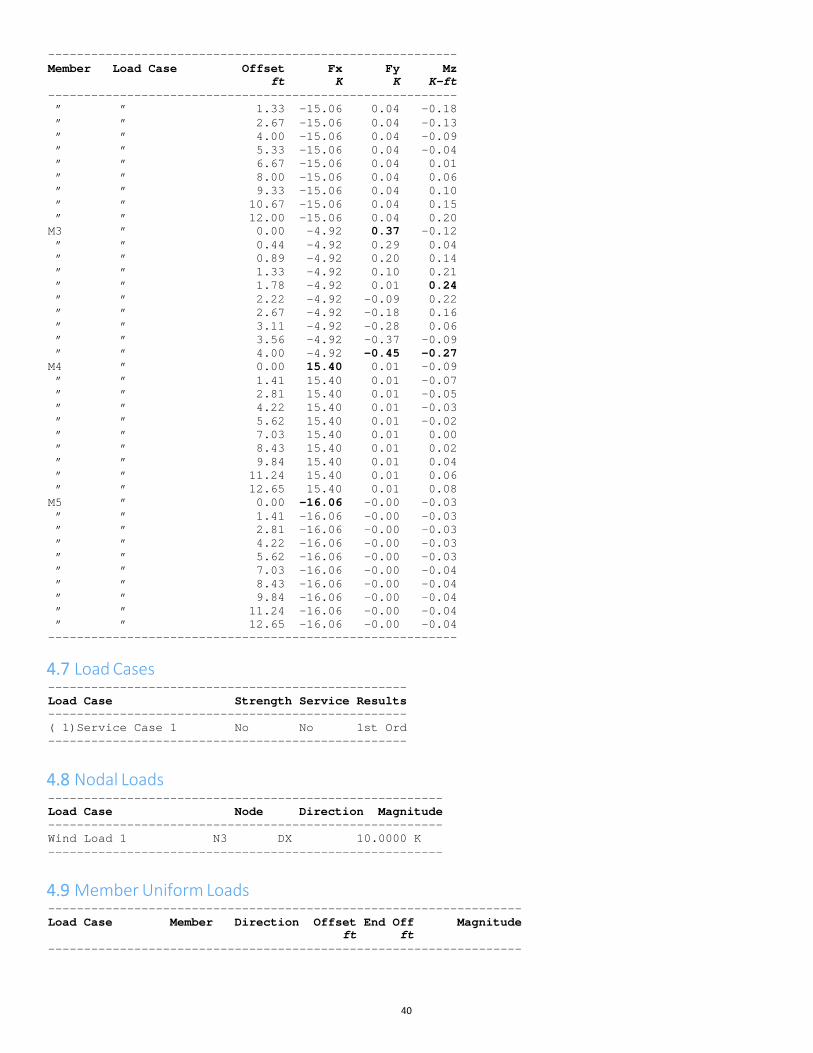
4.6 Member Internal Forces ————————————————————————————————————————————————————————— Member Load Case Offset
ft FxK
FyK
MzK-ft
—————————————————————————————————————————————————————————M1 Service Case 1 0.00 14.87 0.00 -0.09” ” 1.33 14.87 0.00 -0.09” ” 2.67 14.87 0.00 -0.09” ” 4.00 14.87 0.00 -0.09” ” 5.33 14.87 0.00 -0.09” ” 6.67 14.87 0.00 -0.08” ” 8.00 14.87 0.00 -0.08” ” 9.33 14.87 0.00 -0.08” ” 10.67 14.87 0.00 -0.08” ” 12.00 14.87 0.00 -0.08
M2 ” 0.00 -15.06 0.04 -0.23
40
—————————————————————————————————————————————————————————Member Load Case Offset
ft FxK
FyK
MzK-ft
—————————————————————————————————————————————————————————” ” 1.33 -15.06 0.04 -0.18” ” 2.67 -15.06 0.04 -0.13” ” 4.00 -15.06 0.04 -0.09” ” 5.33 -15.06 0.04 -0.04” ” 6.67 -15.06 0.04 0.01” ” 8.00 -15.06 0.04 0.06” ” 9.33 -15.06 0.04 0.10” ” 10.67 -15.06 0.04 0.15” ” 12.00 -15.06 0.04 0.20
M3 ” 0.00 -4.92 0.37 -0.12” ” 0.44 -4.92 0.29 0.04” ” 0.89 -4.92 0.20 0.14” ” 1.33 -4.92 0.10 0.21” ” 1.78 -4.92 0.01 0.24” ” 2.22 -4.92 -0.09 0.22” ” 2.67 -4.92 -0.18 0.16” ” 3.11 -4.92 -0.28 0.06” ” 3.56 -4.92 -0.37 -0.09” ” 4.00 -4.92 -0.45 -0.27
M4 ” 0.00 15.40 0.01 -0.09” ” 1.41 15.40 0.01 -0.07” ” 2.81 15.40 0.01 -0.05” ” 4.22 15.40 0.01 -0.03” ” 5.62 15.40 0.01 -0.02” ” 7.03 15.40 0.01 0.00” ” 8.43 15.40 0.01 0.02” ” 9.84 15.40 0.01 0.04” ” 11.24 15.40 0.01 0.06” ” 12.65 15.40 0.01 0.08
M5 ” 0.00 -16.06 -0.00 -0.03” ” 1.41 -16.06 -0.00 -0.03” ” 2.81 -16.06 -0.00 -0.03” ” 4.22 -16.06 -0.00 -0.03” ” 5.62 -16.06 -0.00 -0.03” ” 7.03 -16.06 -0.00 -0.04” ” 8.43 -16.06 -0.00 -0.04” ” 9.84 -16.06 -0.00 -0.04” ” 11.24 -16.06 -0.00 -0.04” ” 12.65 -16.06 -0.00 -0.04
—————————————————————————————————————————————————————————
4.7 Load Cases —————————————————————————————————————————————————— Load Case Strength Service Results —————————————————————————————————————————————————— ( 1)Service Case 1 No No 1st Ord ——————————————————————————————————————————————————
4.8 Nodal Loads ——————————————————————————————————————————————————————— Load Case Node Direction Magnitude ——————————————————————————————————————————————————————— Wind Load 1 N3 DX 10.0000 K ———————————————————————————————————————————————————————
4.9 Member Uniform Loads —————————————————————————————————————————————————————————————————— Load Case Member Direction Offset End Off Magnitude
ft ft ——————————————————————————————————————————————————————————————————


41
Appendix D – Cable Tie Crossing
Filo Verde Final Report.docx
Crossing Calcs.mcdx
⎝
12/12/2014 River Crossing Calculations iDesign ABC's Inc. Caitlin Wotruba
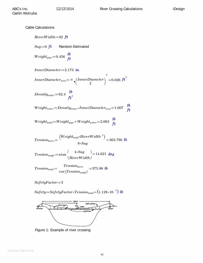
Cable Calculations
RiverWidth ≔ 92
Sag ≔ 6 Random Estimated
Weightpipe ≔ 0.456
InnerDiameter ≔ 2.173
InnerDiameterarea ≔
2
•⎛ InnerDiameter ⎞
2
= 0.026 ⎝ 2 ⎠
Densitywater ≔ 62.4
Weightwater ≔ Densitywater ⋅ InnerDiameterarea = 1.607
Weighttotal ≔ Weightpipe + Weightwater = 2.063
⎛Weighttotal ⋅ RiverWidthTensionhoriz ≔
8 ⋅ Sag
2 ⎞⎠= 363.786
⎛ Tensionangle ≔ atan
4 ⋅ Sag ⎞ = 14.621
⎝ RiverWidth ⎠
Tensiontotal ≔ Tensionhoriz
cos ⎝Tensionangle⎠ = 375.96
SafetyFactor ≔ 3
Safety ≔ SafetyFactor ⋅ Tensiontotal = ⎛⎝1.128 ⋅ 10 3 ⎞⎠
Figure 1: Example of river crossing
3
42

Crossing Calcs.mcdx 43
12/12/2014 River Crossing Calculations iDesign ABC's Inc. Caitlin Wotruba
From Appendix A-2
BreakStrengthsize1 ≔ 1700 7x7 1/8
BreakStrengthsize2 ≔ 2000 7x19 1/8
SafeLoadsize1 ≔ BreakStrengthsize1
3 = 566.667
SafeLoadsize2 ≔ BreakStrengthsize2
3 = 666.667
BreakStrengthfinalsize ≔ 1700 7x7 1/8
DesignSag ≔
2
Weighttotal ⋅ RiverWidth = 1.284
8 ⋅ BreakStrengthfinalsize
DesignSag ≔ 1.75 Design Value to be used
Crossing Calcs.mcdx 44
12/12/2014 River Crossing Calculations iDesign ABC's Inc. Caitlin Wotruba
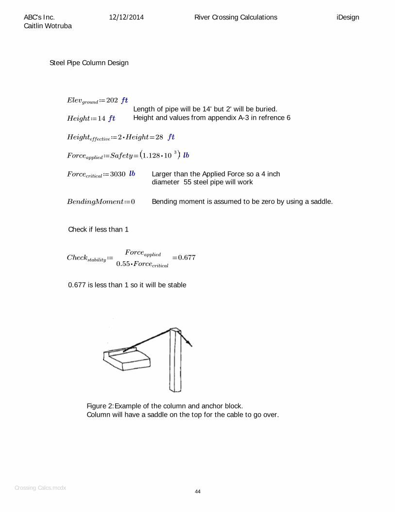
Steel Pipe Column Design
Elevground ≔ 202
Height ≔ 14
Length of pipe will be 14' but 2' will be buried. Height and values from appendix A-3 in refrence 6
Heighteffective ≔ 2 ⋅ Height = 28
Forceapplied ≔ Safety = ⎛⎝1.128 ⋅ 10 3 ⎞⎠
Forcecritical ≔ 3030 Larger than the Applied Force so a 4 inch diameter 55 steel pipe will work
BendingMoment ≔ 0 Bending moment is assumed to be zero by using a saddle.
Check if less than 1
Checkstability ≔ Forceapplied
0.55 ⋅ Forcecritical
= 0.677
0.677 is less than 1 so it will be stable
Figure 2:Example of the column and anchor block. Column will have a saddle on the top for the cable to go over.

Crossing Calcs.mcdx 45
check
12/12/2014 River Crossing Calculations iDesign ABC's Inc. Caitlin Wotruba
Mass Block Anchor Design
Forcetotal ≔ Safety = ⎛⎝1.128 ⋅ 10
Dist ≔ 10
3 ⎞⎠ Tower is 14ft (Height) tall and anchor is 10ft (Dist) back from tower.
Forcehoriz ≔ Dist ⋅ Forcetotal
2 = 655.568
2
(Height) + (Dist)
Forcevert ≔ Height ⋅ Forcetotal
2 = 917.795
2
(Height) + (Dist)
At least 1.5' of the height should be buried.
H ≔ 4.25 W ≔ 3 Mass ≔ 150 3
Calculate the value for L so that the anchor block will not overturn by summing the forces.
Lsquare ≔ 2 ⋅ Forcehoriz ⋅ H ⋅ SafetyFactor
W ⋅ H ⋅ Mass
2
= 8.741
L ≔ Lsquare = 2.957
L ≔ 3 Rounded value
Check for Sliding by balancing the horizontal forces and checking the factor of safety.
φ ≔ 17 Used value for Organic Clay of high Plasticity from refrence 8
Safety ≔ ⎝L ⋅ W ⋅ H ⋅ Mass ⋅ tan (φ) + Forcevert
Forcehoriz
⎠ = 4.076
The check of the factor of safety is good since it was 4.076 which is higher than the value of 3 that was used.

Crossing Calcs.mcdx 46
12/12/2014 River Crossing Calculations iDesign ABC's Inc. Caitlin Wotruba
Figure 3: Example of Mass Anchor block and rebar
Stringer Length
x ≔ RiverWidth
= 46 2
DesignSag = 1.75
Sagratio ≔ DesignSag
x = 0.038
C ≔ 3.295788 ⋅ RiverWidth = 303.212
C is a constant and equals the river width times 3.295788 from Appendix A-4 in refrence 6

Crossing Calcs.mcdx 47
12/12/2014 River Crossing Calculations iDesign ABC's Inc. Caitlin Wotruba
Stringer locations will be at 5ft, 15ft, 25ft, and 35ft from the apex. The values for the length of the stringer are calculated using the C value. x1 ≔ 5 x2 ≔ 15 x3 ≔ 25 x4 ≔ 35
y1 ≔ C ⋅ cosh ⎛ x1 ⎞
⎝ C ⎠ − C = 0.495
y2 ≔ C ⋅ cosh ⎛ x2 ⎞
⎝ C ⎠ − C = 4.453
y3 ≔ C ⋅ cosh ⎛ x3 ⎞
⎝ C ⎠ − C = 12.375
y4 ≔ C ⋅ cosh ⎛ x4 ⎞
⎝ C ⎠ − C = 24.267
Normalize the values
Length is added for the 1/8 in cable to wrap around the eyelet and around the pipe which has an outside diameter of 2.375 inches.
ExtraLength ≔ 4 ⋅ 4 + 2 ⋅ 2.375 ⋅ = 30.923
y5 ≔ y1 − y1 + ExtraLength = 30.923
y15 ≔ y2 − y1 + ExtraLength = 34.881
y25 ≔ y3 − y1 + ExtraLength = 42.802
y35 ≔ y4 − y1 + ExtraLength = 54.695
Adjust to reasonable values y5 ≔ 31
y15 ≔ 35
y25 ≔ 43
y35 ≔ 54.75
Stringertotal ≔ y5 + y15 + y25 + y35 = 163.75

Crossing Calcs.mcdx 48
12/12/2014 River Crossing Calculations iDesign ABC's Inc. Caitlin Wotruba
Final Cable Length
y ≔ C ⋅ sinh ⎛ x ⎞
= 46.177 ⎝ C ⎠
Total Length Along the Arc
Lengthtotal ≔ y ⋅ 2 = 92.353
Change in Length using 7x7 1/8 steel cable
⎛ 0.2 ⋅ BreakStrengthfinalsize ⎞ ⎛ Tensiontotal − 0.2 ⋅ BreakStrengthfinalsize ⎞ Δlength ≔ ⎜
2 ⎟ + ⎜
2 ⎟ = 0.004 ⎜ 0.0074 ⎝
⋅ 13500000 ⎟ ⎜ 2
⎠ ⎝ 0.0074 ⋅ 15000000 ⎟
2
⎠
Lengthstart ≔ Lengthtotal
1 + Δlength
= 92.01
Lengthneed ≔ Lengthstart + 2 ⋅ 2
(10 ) 2
+ (12 ) = 123.251

Filo Verde Final Report.docx
49
Appendix E ‐ Maps and Profiles

Filo Verde water distribution systems elevation profiles.docx
50
December 12, 2014 ABC’s Inc.
Zichao Wang Filo Verde Elevation Profiles
Filo Verde Water Distribution System Elevation Profiles ABC’s Inc.
Figure 1: Filo Verde General Map

Filo Verde water distribution systems elevation profiles.docx
51
ABC’s Inc. Zichao Wang Filo Verde Elevation Profiles December 12, 2014
Figure 2: General Map Parts
The General Map is divided into three parts:
Part A: current water distribution system (White path)
Part B: new spring source (Red path)
Part C: taps in the community (Red dots)
o Part C1: Manuel’s tap to bridge over Río Sucio
o Part C2: Eduardo’s tap to past school
o Part C3: Center of the bridge over Río Sucio to the current water tank

Filo Verde water distribution systems elevation profiles.docx
52
ABC’s Inc. Zichao Wang Filo Verde Elevation Profiles December 12, 2014
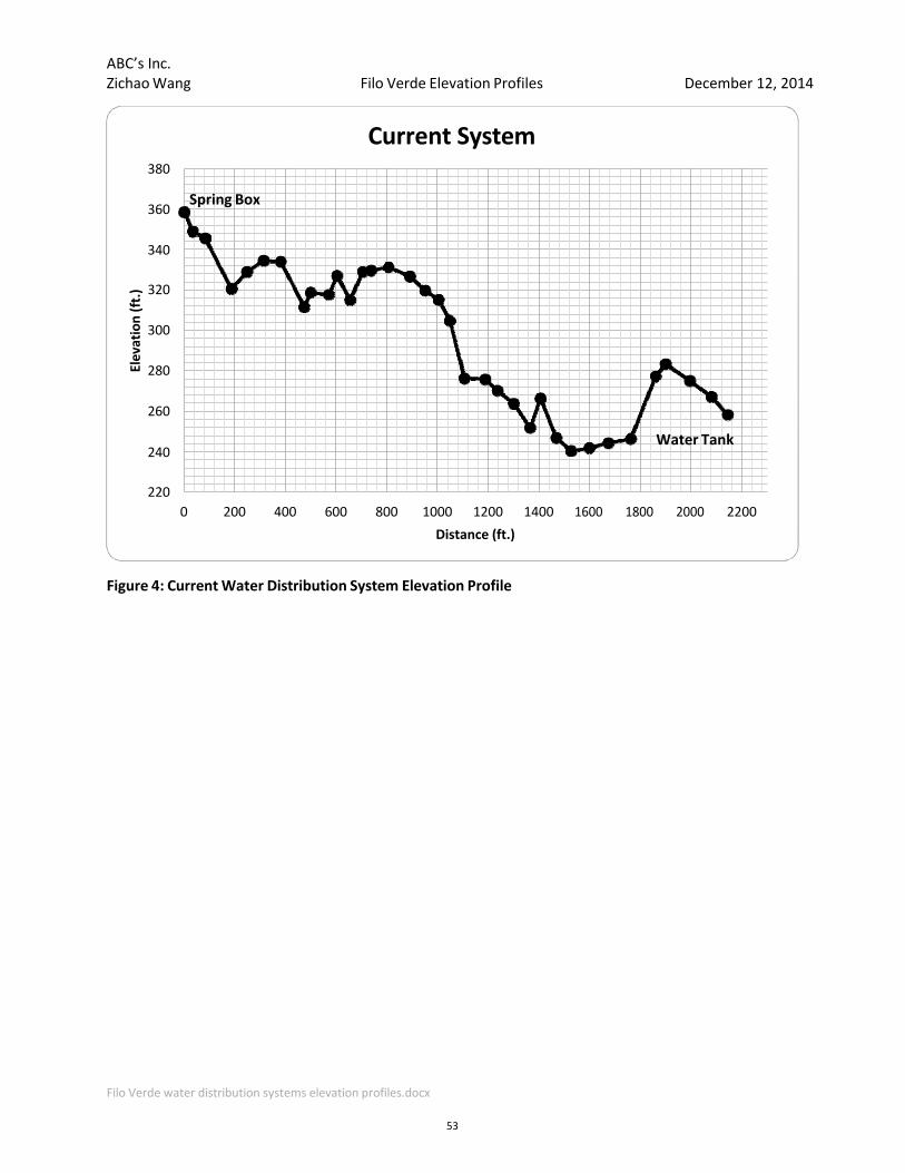
Figure 3: Current Water Distribution System (White Path)
Filo Verde water distribution systems elevation profiles.docx
53
ABC’s Inc. Zichao Wang Filo Verde Elevation Profiles December 12, 2014
Figure 4: Current Water Distribution System Elevation Profile
Current System380
360 Spring Box
340
320
300
280
260
Water Tank240
220
0 200 400 600 800 1000 1200 1400 1600 1800 2000 2200
Distance (ft.)
Elevation (ft.)

Filo Verde water distribution systems elevation profiles.docx
54
ABC’s Inc. Zichao Wang Filo Verde Elevation Profiles December 12, 2014
Figure 5: New Spring Source (Red Path)

Filo Verde water distribution systems elevation profiles.docx
57
ABC’s Inc. Zichao Wang Filo Verde Elevation Profiles December 12, 2014
260
255
250
245
240
235
230
225
220
215
210
0 100 200 300 400 500 600 700 800 900
Distance (ft.)
Figure 8: Manuel’s Tap to Bridge Elevation Profile (Blue Path)
Manual's Tap
Start of Bridge
Middle
of Bridge
Elevation (ft.)

Filo Verde water distribution systems elevation profiles.docx
58
ABC’s Inc. Zichao Wang Filo Verde Elevation Profiles December 12, 2014
Figure 9: Eduardo’s Tap to Past School Elevation Profile (Red Path)
Eduardo's Tap
Eduardo's Tap to Past School260
255
250
245
240
235
0 200 400 600
Distance (ft.)
800 1000 1200
Elevation (ft.)
Filo Verde water distribution systems elevation profiles.docx
59
ABC’s Inc. Zichao Wang Filo Verde Elevation Profiles December 12, 2014
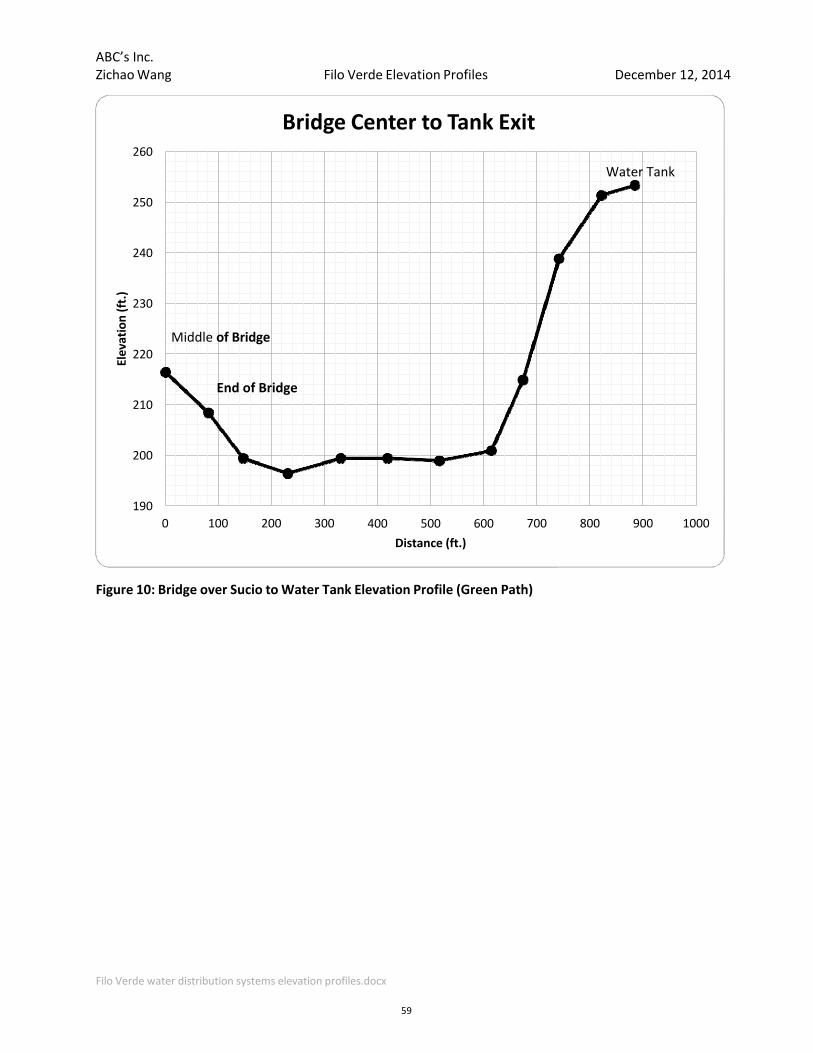
Figure 10: Bridge over Sucio to Water Tank Elevation Profile (Green Path)
Middle of Bridge
End of Bridge
Bridge Center to Tank Exit260
250
240
230
220
210
200
190
0 100 200 300 400 500 600
Distance (ft.)
700 800 900 1000
Elevation (ft.)
Water Tank

Filo Verde water distribution systems elevation profiles.docx
55
ABC’s Inc. Zichao Wang Filo Verde Elevation Profiles DecemDecember 12, 2014
Figure 6: New Spring Source Elevation Profile

Filo Verde water distribution systems elevation profiles.docx
56
ABC’s Inc. Zichao Wang Filo Verde Elevation Profiles December 12, 2014
Figure 7: Faucets and River Crossing (Part C)
Part C1: Blue route is the route from Manuel’s tap to bridge over Río Sucio
Part C2: Red route stands for route from Eduardo’s tap to past school
Part C3: Green route is the route from the center of bridge over Río Sucio to current water tank


Filo Verde Final Report.docx
60
Appendix F ‐ Cost Estimate
Categories (Components): % Total Cost
Materials: 79.5%
Materials Current System: 8%
Materials New System: 53%
Materials River Crossing: 18%
Labor: 19.2%
Labor Current System: 3%
Labor New System: 14%
Labor River Crossing: 3%251.63$
133.27$
9,837.71$ Total Cost:
1.4%Equipment:
1,813.33$
1,888.17$
247.20$
1,389.33$
Costs ($)
7,816.28$
829.94$
5,173.01$
Materials Current System:8%
Materials New System:53%
Materials River Crossing:18%
Labor Current System:3%
Labor New System:14%
Labor River Crossing:
3%
Equipment:1%
Total Cost Estimate: Breakdown by Components
Materials:80%
Labor:19%
Equipment:1%
Total Cost Estimate: Breakdown by Categories
$133.27
$1,888.17
$7,816.28
61

Cost Estimate
Filo Verde Water Distribution System
ABC's Inc.
Item # Item Unit Quantity Material Unit
Cost Materials Labor Unit Quantity Labor Unit Time Labor (days) Labor (Costs) Equipment Equipment
1 2" PVC Pipe LF 60 0.47$ 28.20$
2 2" PVC Cut‐Off Valve EA 10 3.00$ 30.00$
3 2" PVC Joints EA 4 1.00$ 4.00$
4 PVC Glue OZ 2.13 0.20$ 0.43$
5 Portland Cement LBS 3666 0.10$ 361.53$
6 Construction Sand LBS 8,580 ‐$ ‐$
7 Crushed Gravel LBS 14,040 ‐$ ‐$
8 No. 3 Rebar LF 701.5 0.52$ 364.78$
9 Welded Wire Fabric SF 250 41.00$ 41.00$
829.94$ 5.00 $ 247.20 Current Water Distribution Equipment: $ ‐
10 2" PVC Pipe LF 8000 0.47$ 3,760.00$
11 2" PVC Valves EA 1 3.00$ 3.00$
12 2" PVC Joints EA 430 1.00$ 430.00$
13 PVC Glue OZ 229.3 0.20$ 45.87$
14 Portland Cement LBS 2160 0.10$ 213.01$
15 Construction Sand LBS 5053 ‐$ ‐$
16 Crushed Gravel LBS 8,269 ‐$ ‐$
17 No. 3 Rebar LF 90 0.52$ 46.80$
18 Welded Wire Fabric SF 0 41.00$ ‐$
19 600 gallon Plastic Water Tank EA 1 475.00$ 475.00$
20 Wood Pieces 52" x 8" x 2" EA 18 ‐$ ‐$
21 Wood Columns 12' x 4" x 4" EA 4 ‐$ ‐$
22 Wood Bracing 12.75' x 4" x 2" EA 8 ‐$ ‐$
23 Nails EA 765 0.01$ 9.87$
24 8" x 8" x 1/8" Steel Connection Plate EA 4 5.23$ 20.92$
25 A21Z Galvanized 18‐Gauge Angle EA 16 0.58$ 9.28$
25 Corrogated Galvanized Steel Sheet EA 2 27.05$ 54.10$
26 1/2 in. x 8 in. Carriage Bolt EA 44 1.53$ 67.32$
27 1/2 in. Galvanized Hex Nut EA 44 0.53$ 23.32$
28 1/2 in. Galvanized Cut Washer EA 44 0.33$ 14.52$
29 Wrenches EA 10 3.33$ ‐$ $ 33.27
30 Shovels EA 10 10.00$ ‐$ 100.00$
5,173.01$ 24.00 $ 1,389.33 New Water Distribution Equipment: $ 133.27
31 4" Dia. Steel Pipe Tower LF 28 15.00$ 420.00$ LF/day 28 50 0.56
32 Steel Cable 7x7 1/8 LF 525 0.32$ 168.00$
33 Steel Cable Stringers 1/8" LF 225 0.32$ 72.00$
34 Cable Eyelets EA 8 $ 1.98 15.84$
35 Cable Clamps EA 40 $ 0.52 20.80$
36 2" PVC Pipe LF 460 0.47$ 216.20$
37 2" PVC Joints EA 23 1.00$ 23.00$
38 3" PVC Pipe LF 460 1.35$ 621.00$
39 3" PVC Joints EA 23 3.00$ 69.00$
40 PVC Glue OZ 12.27 0.20$ 2.45$
41 Portland Cement LBS 1633 0.10$ 161.04$
42 Construction Sand LBS 3821 ‐$ ‐$
43 Crushed Gravel LBS 6252 ‐$ ‐$
44 Welded Wire Fabric SF 0 $ 41.00 ‐$
45 Turnbuckle EA 2 $ 10.00 20.00$
46 No. 3 Stirrup EA 2 2.00$ 4.00$
1,813.33$ 5.00 251.63$ River Crossing Equipment: ‐$
7,816.28$ 1,888.17$ Total System Equipment Cost: 133.27$ Total System Materials Cost:
Current Water Distribution Rehab Cost:
New Water Distribution System Cost:
River Crossing Cost:
Currrent Water Distribution Rehab Labor:
New Water Distribution Labor:
River Crossing Labor:
18 6
460
4
Total System Labor Cost:
45
500
525 200
River Crossing
Reh
abilitation ‐ curren
t system
LF/day
CF/day
LF/day
CF/day
New W
ater Distribution System
Pieces/day
LF/day
CF/day
LF/day
LaborMaterials Equipment
3.00
60
180
500
8000
187 45
500
0.12
4.00
16.00
4.16
45
2.63
0.92
0.09
62

Filo Verde Final Report.docx
63
Appendix G ‐ Construction and Maintenance Manual

Filo Verde Final Report.docx
64
Construction and Maintenance Manual
1.0 PVC Pipe There will need to be extensive amounts of PVC pipe installed during the Filo Verde water
distribution system update. The PVC pipe will need to be installed carefully so as not to damage the structure of the pipe. In order to install it this way, the pipe should be buried in all locations possible, which includes the route along the pathway from the new spring source to the river crossing at Río Caño Sucio. There should be a trench excavated with sufficient room for the piping to be buried 1.5-‐foot wide by 1.5-foot deep should be sufficient for this purpose. If granular material is available, it should be placed at the bottom of this trench as a stronger base for the PVC piping to lay on. From the river crossing to the tank, the piping will be elevated and burying the PVC pipe will not be necessary. At an elevation of 700‐feet and an elevation of 400‐feet, the piping will need to be directed into pressure break tanks in order to not break the pipe from high internal pressures caused by the elevation head of the system. More information on how the piping should be directed is in the “Pressure Break Tank” section of this manual.
In connecting pipes, both ends of PVC pipe being connected must be clean and dry (i.e. no dirt or water present on the last 3‐inches of pipe). These ends must be coated in glue and connected with the joint specified. Most joints for the system will be 180-degree joints, except for the following: there will be two 90-degree joints at each pressure break tank. For these exceptions, installation procedure is the same as for the straight joints.
The PVC pipe will be delivered in 20-foot pieces and therefore will be reasonably difficult to carry. There should be at minimum two people carrying these pieces, with one near each end. Multiple pieces of the piping can be carried by this two‐person team. Carrying the piping in this manner will decrease the danger of breaking the pipe from bending.
If pipes break anywhere in the system, they will need to be fixed as soon as possible so as not to lose a large volume of water. The proper procedure for fixing a broken pipe is to first stop flow into that portion of the pipe for the duration of the maintenance. This will allow for a dry surface to fix, which makes a better seal. After the flow is stopped and location of the break is dried, the broken section will be cut out and then rejoined with the rest of the system using a coupling and a proper amount of glue (~2 ounces). If the section cut out is large (greater than 6‐ inches), a new section of PVC pipe must be cut to the broken section size, and inserted into the system using two couplings and PVC glue (~4 ounces).
2.0 Mixing Concrete All concrete in the new and old system shall be mixed as follows, including but not limited to the
following: the new source spring box, pressure break tanks, new tank to be built for the current system, and various anchors.
Before the concrete can be mixed, forms must be set. The forms will be made of wood that is not warped. In order to ensure that the form is straight, posts will set set around the perimeter of the form every foot. To stay straight, despite the pressure from the form wood and the concrete that will be placed, these posts must be placed at least 1‐foot into the ground. Forms will be made based on the dimensions given for each part of the system, making sure that the dimensions are measured from the innermost section of the wood. Once the forms are set, the concrete can be poured.
Concrete will be mixed thoroughly using a 1:2:3 ratio of cement to sand to gravel. The concrete will be a 1:2 water to cement ratio for the mixture throughout the system. The first step in

Filo Verde Final Report.docx
65
mixing concrete is to mix the fine aggregate (sand) and Portland cement together into a homogeneous mixture. Next, the coarse aggregate will be added, followed by the water. The water needs to be added slowly in order to slowly make the mixture plastic enough to form. This will create a strong concrete for all structures in the Filo Verde water distribution system.
Once the concrete mixture is at a workable consistency ‐ where the concrete can flow ‐ it will be poured into the already made forms. As the concrete is poured, a rod must be inserted into the mixture throughout the form to ensure no air is entrapped in the mixture, which could weaken the concrete. The sides of the form must also be tapped throughout the process of pouring to further ensure that there is no entrapped air in the concrete. Once the form is filled, the concrete should be leveled using a float or a small, flat board. The time until the slab is dried is dependent upon the amount of concrete poured as well as the thickness of the concrete.
3.0 Spring Box The spring box for the new source will be a reinforced concrete wall and tank structure. The
walls will be 4‐feet long on both sides from the edges of the 22” x 3’ x 3’ (L x W x H) tank, which is modeled in Appendix B. The tank will have a 4-inch concrete cover from the end of one wall to the end of the other wall. This cover will be reinforced using welded wire fabric.
The spring box concrete will be mixed and poured as outlined in Section 2.0 of this manual. The forms for the walls and the tank will be placed, then the No.3 rebar will be inserted every 6‐ inches along the wall, and finally the concrete will be poured for those sections. There must be a concrete cover of 2‐inches on the top and bottom of the wall, per ACI specifications. After allowing these sections to dry (roughly one day), the concrete cover can be formed, reinforced with welded wire fabric, and poured. In order to connect the cover with the walls, the top 4‐inches of concrete for the walls will be poured on the same day as the concrete cover. This will allow the No. 3 rebar in the walls to connect with the welded wire fabric in the cover, and provide a continuously reinforced structure.
4.1 Pressure Break Tanks There will be two pressure break tanks in the new addition to the Filo Verde water distribution
system. These tanks will be two chambers, both the same size (3’ x 4’ x 2’ – L x W x H); with overall tank dimensions of 6’ x 4’ x 2’ (L x W x H), and 6” thick. The tank will also include a corrugated galvanized steel sheet (CGS) that will be bolted to the concrete structure and used as a roof for protection from elements. The tank will be 1‐foot in the ground with a layer of gravel and coarse materials underneath, therefore excavation of the site must take place before any more work can be completed [6].
The pressure break tanks will be mixed and poured as outline in Section 2.0 of this manual. The forms for the walls and the tank will be placed and the concrete will be poured. There will be no reinforcement in the pressure break tanks. The floors must be made sloping downhill so the water will flow correctly through the tank and continue to flow towards the rest of the system. The concrete slab at the bottom of the uppermost section will be measured as 8‐inches, and this will decrease steadily until the outlet, where the concrete will be only 4‐inches thick at the floor (~0.074‐inch decrease vertically for every 1‐inch horizontal).
In addition, there must be a special corrosion-resisting portion of the pressure break tank. This will be in order to reduce corrosion when the water enters the tank. A special mortar will be mixed for this section as follows [6]:
1:1:4 (water : sand : cement) mix will be coated 1/3‐inch thick and left with a rough surface

Filo Verde Final Report.docx
66
1:1:3 mix will be coated 1/3‐inch thick and left with a rough surface 1:1:2 mix will be coated 1/3‐inch thick and left with a smooth surface
For this plastering to work, the floor level must be initially laid 1-inch less than specified 7-‐inches thick at the uppermost part as opposed to the specified 8-inches to account for the layers of plaster. If plastering is not a feasible option, but a hard flat rock can be found, this may be placed instead of plaster at the base of the tank where the water enters the tank. If this option were to be used, the rock must be cleaned with treated water so as not to pollute the water flowing downstream.
In order to attach the corrugated galvanized steel roof to the tanks, bolts must be installed during the concrete‐pouring process. These bolts will be placed one hour after the concrete has been poured so they do not sink into the concrete. There will be bolts placed on each corner as well as two additional bolts placed in the middle of the longer sides of the tanks. The bolts will be placed with threaded portions vertical so that the roof may be attached and bolted down as shown below in Figure 1 [6].
5.0 Wooden Platform The wooden platform for the system will bebuilt like the community houses are built, with
additional measures to be taken for safety. First, four holes must be excavated 1’ x 1’ x 2’ (L x W x D) at each corner of the platform base (52” from one another on center, in a square pattern). Concrete, mixed as outlined in Section 2.0 of this manual, will be placed in these holes. Bolts, placed as shown in Section 4.0 of this manual will be installed in the concrete as well, 8 per plate, as detailed (in inches) in Figure 2.
Figure 1: Bolt Detail
Figure 2: Connection Detail

Filo Verde Final Report.docx
67
There will be one 10” x 10” x 3/8” (L x W x t) plate on every concrete pad with a 1/2” hole 1” from each corner and four more 1/2” holes where the angles will sit. Four steel angles will be installed on the steel plates as shown in the figure. In the center of each plate on the concrete pad, the 4 columnswill be installed. The angles will be bolted into the wood column at the base. The concrete, steel, and bolts will provide the column a strong support.
While the concrete is drying for the base of the platform, the platform top can be built. First, four pieces of 52” x 8” x 2” (L x W x t) wood will be nailed together in a square form, as shown in the model in Appendix K. Then, the six pieces of similar sized wood (52” x 8” x 2”) will be nailed to the top of the square frame. These will have 1/8” gaps between each board as they are laid across the square frame. This will allow any rainfall to reach the ground so as not to rot the wood.
Once the frame for the top of the platform has been built and the columns are in place on the concrete pads, the frame can be placed carefully on the top of the columns and nailed in. Bracing will need to be installed soon after the frame and columns have been attached. The bracing for this structure will be in the form of two 12.75’ x 4” x 2” (L x W x t) pieces of wood crossed on each side. These will be nailed at each corner in order to provide stability. After the structure has been built, a ladder must be built in order to access the top of the platform.
The final part in building the wooden platform will be installing the new plastic water tank. The tank will need to be placed carefully on top of the platform in the middle of the floor boards. In order to keep the tank on the top of the platform, four pieces 36” x 8” x 2” wood will be installed at the middle of each portion of the platform. These will be connected by four 52” x 8” x 2” pieces of wood, similar to how the frame was built initially for the top of the platform. This will ensure the plastic water tank will not be at risk of tipping off the top of the platform.
6.0 Cut‐Off Valves Cut-off valves are to be installed in ten locations throughout the community. To install, the
water must first be stopped so a good seal can be maintained. Once a location has been chosen, the pipe must be unburied. Then a small area of the PVC pipe, slightly smaller than the length of the cut‐off valve, should be cut with enough room to insert of each side of the PVC into the valve. Insert the cut‐off valve onto the PVC pipe. Use adhesive on the PVC to make a solid connection on one end then do the same to the other side of the valve. Make sure any adhesive dries before reburying the piping [11].
7.0 New Two‐Chamber Tank for Current System The new two‐chamber tank for the current system will include concrete, rebar, welded wire
fabric, and PVC pipe. The concrete for this tank will be mixed as outlined in Section 2.0 of this manual. Extensive forming will need to take place before this tank can be built due to its large size. The floor slab of this structure will need to be poured first, after the forms have been placed and the 12” x 12” rebar grid has been built. The walls for the structure will be built next, with the 4” x 4” spaced welded wire fabric used as reinforcement. Pipes will need to be installed as these walls are erected, so that they can be connected through the walls into the system. Finally, the roof will be formed and poured; the roof will require the most rebar in order to prevent deflections 6” x 6” rebar grid will be sufficient. There will be two openings in the roof, as modeled in Appendix K, for possible maintenance to be performed. These openings will require separate covers to be formed and built that must include two cable handles in order to remove the covers.
8.0 Cable‐tie River Crossing All materials should be present on the site at the beginning so that the crossing can be built at
once. The cables and pipeline should be placed in one day so that they are not damaged overnight during construction.
The steel towers should be placed first by excavating a hole that is 2‐feet deep and 1‐foot

Filo Verde Final Report.docx
68
square. This should be filled with concrete that is mixed according to the specifications in section 2.0. The saddle should be attached to the top of the tower before placing it in the concrete. Then the steel tower should be placed in the concrete so that it is 2‐feet deep. If the tower is vertical when installed and after the cable forces are applied then the bending moment will be eliminated. It is best to have a person watching the tower during the entire construction process with either a level or a plumb line so make sure that it stays vertical.
After the towers are set, the anchors can be placed behind the towers so that everything is in line. The forms should be built according to the specifications in the design and the rebar should be placed in the correct locations; figure 3 in Appendix D shows an example of the rebar. A turnbuckle will be added on each side of the river crossing between the tower and the anchor. The purpose of the turnbuckle is to adjust the tension in the cable. The cable will be attached to both ends of the turnbuckle with two clamps on each side of the turnbuckle to hold the cable. The tension can then be increased or decreased by turning the frame of the turnbuckle the respective direction. The concrete for the anchors should follow the concrete mixing specifications in section 2.0. An example of this design is shown in Figure 3.
The distance for the cable should be measured again to account for any differences in the construction from the design. The cable and stringers should be measured to be the correct distance. It is most efficient if the stringers are all prepared ahead of time. The two top clamps that hold the eyelet in place should be attached. The bottom of the two clamps should be attached and tightened first with the correct turnback length. Then the clamp above it should be placed directly above it loosely so that the eyelet could be formed. After the eyelet is formed the second clamp can be slid up and tightened to hold the eyelet in place.
Next the bottom of the stringer can be set for the correct amount of sag by setting the top clamp in the correct position and the second one loosely so that the double loop can be slid around the pipe and the clamp tightened during construction.
There are two parts to the clamp, the staple and the saddle. The staple is the portion is shaped like a horseshoe, and the nuts are attached to the ends of it. The saddle is the steel piece with two holes in it. The cable where the clamps attach also has two parts. There is the live cable that supports the load and the dead cable which is the cable that is turned back. The saddle should always go on the live cable because the saddle grips the cable smoothly.
The best way to place the stringers is to first attach the main cable on both sides with the stringers already on the cable. Then the pipe is all pushed from one side of the river. It is best to cover the end of the first pipe so that no dirt will get into the system, and to attach a string to the end so that the pipes can be pulled across the river as well as pushed from the other side. As the pipe is pushed across the stringers will be wrapped around the pipe at the correct location and the pipes should be connected as needed for it to span the river crossing.
Figure 3: Cable-tie Crossing Detail
Filo Verde Final Report.docx
69
9.0 In‐home water treatment Either chlorine or boiled water should be used to make water safe to use in the community
members homes. Each home should choose which solution works for them since both are adequate to kill all bacteria present in the water. Chlorine treatment can be found in the community store for those that choose to use this treatment.
The desired amount of water to be used must be selected to use chlorine treatment. From this amount, the number of chlorine drops necessary can be found on the chlorine bottle (approximately 8 drops of chlorine are needed per gallon of water). This method may be best for the emergency buckets each house has in case their water is not working.
The second treatment method – boiling – does not require a certain amount of water to work. To boil, water should be placed in a fire-safe container and set over a fire until it begins to bubble and boil, then keep the water at this temperature for 2-3 minutes. This method works best for drinking water and for cooking.
10.0 Maintenance
The new system should be inspected on an annual basis. This inspection should include all parts of the system listed above. The masonry parts of the system – the spring box, pressure break tanks, new water storage tank, and the river crossing anchors – should be checked for cracks. If any cracks are found, a mortar mix of 1:1:3 should be mixed (1 part water per 1 part sand per three parts cement) to fill the cracks. The piping in the system must also be checked on a bi-monthly basis. Any cracks identified in the PVC piping will need to be fixed as outlined in Section 1.0 of this manual. The wooden platform must be checked for rotting on a bi‐monthly basis. If any rotting pieces of wood are identified, they must be replaced immediately.

Filo Verde Final Report.docx
70
Appendix H – Schedule

71
ID Task Task Name Duration Start Finish Pre Mod
1 Buy and Transport materials 4 days Fri 1/2/15 Sat 1/10/15
2 Buy Materials 2 days Fri 1/2/15 Sat 1/3/15
3 Transport Materials 2 days Fri 1/9/15 Sat 1/10/15 2
4 New System 45 days Fri 1/16/15 Fri 6/19/15 1
5 Spring Box 7 days Fri 1/16/15 Fri 2/6/15
6 Transport Materials to Spring 2 days Fri 1/16/15 Sat 1/17/15
7 Excavate for Spring 1 day Fri 1/23/15 Fri 1/23/15 6
8 Build Forms 1 day Fri 1/23/15 Fri 1/23/15
9 Set Rebar 1 day Sat 1/24/15 Sat 1/24/15 8
10 Pour Concrete 3 days Fri 1/30/15 Fri 2/6/15 9
11 Pressure Break Tank 5 days Fri 2/20/15 Fri 3/6/15 30
12 Transport Materials to Site 2 days Fri 2/20/15 Sat 2/21/15
13 Build Forms 1 day Fri 2/27/15 Fri 2/27/15 12
14 Set Rebar 1 day Fri 2/20/15 Fri 2/20/15
15 Pour Concrete 2 days Sat 2/28/15 Fri 3/6/15 13
16 River Crossing 8 days Fri 3/20/15 Sat 4/11/15 31
17 Transport Materials to River Crossing1 day Fri 3/20/15 Fri 3/20/15
18 Excavate holes for Towers 1 day Sat 3/21/15 Sat 3/21/15 17
19 Place Concrete and Towers 1 day Fri 3/27/15 Fri 3/27/15 18
20 Build Forms for Anchors 1 day Sat 3/28/15 Sat 3/28/15 19
21 Set Rebar for Anchors 1 day Fri 4/3/15 Fri 4/3/15 20
22 String Wire Across 1 day Sat 4/4/15 Sat 4/4/15 21
23 Place Stringers and pipe 2 days Fri 4/10/15 Sat 4/11/15 22
24 Platform 10 days Fri 4/24/15 Sat 5/23/15 32
25 Cut Wood and Transport to Site 4 days Fri 4/24/15 Sat 5/2/15
26 Excavate for Foundation 1 day Fri 5/8/15 Fri 5/8/15 25
27 Place Concrete and Columns 1 day Sat 5/9/15 Sat 5/9/15 26
28 Construct Platform 4 days Fri 5/15/15 Sat 5/23/15 27
29 Piping 38 days Sat 2/7/15 Fri 6/19/15 5
30 Spring Box to Pressure Break Tank 3 days Sat 2/7/15 Sat 2/14/15 5
31 Pressure Break Tank to River Crossin 3 days Sat 3/7/15 Sat 3/14/15 11
32 River Crossing to Tank 2 days Fri 4/17/15 Sat 4/18/15 16
33 Tank to Community 1 day Fri 6/19/15 Fri 6/19/15 35
34 Current System 9 days Fri 5/29/15 Fri 6/26/15
35 New Tank 6 days Fri 5/29/15 Sat 6/13/15 24
36 Transport Materials to Site 1 day Fri 5/29/15 Fri 5/29/15
37 Build Forms 1 day Sat 5/30/15 Sat 5/30/15 36
38 Set Rebar 1 day Fri 6/5/15 Fri 6/5/15 37
39 Pour Concrete 3 days Sat 6/6/15 Sat 6/13/15 38
40 Piping 3 days Fri 6/19/15 Fri 6/26/15 35
41 Add Cut‐Off Valves 2 days Fri 6/19/15 Sat 6/20/15
42 Reroute for new tank 1 day Fri 6/26/15 Fri 6/26/15 41
28, '1 Jan 4, '15 Jan 11, '1 Jan 18, '1 Jan 25, '1 Feb 1, '15 Feb 8, '15 Feb 15, '1 Feb 22, '1 Mar 1, '15 Mar 8, '15 Mar 15, '1 Mar 22, '1 Mar 29, '1 Apr 5, '15 Apr 12, '1 Apr 19, '1 Apr 26, '1 May 3, '15 May 10, '1 May 17, '1 May 24, '1 May 31, '1 Jun 7, '15 Jun 14, '1 Jun 21, '1 J WT F S SMTWT F S SMTWT F S SMTWT F SSMTWT F S SMTWT F S SMTWT F S SMTWT F SSMTWT F S SMTWT F S SMTWT F S SMTWT F S SMTWT F S SMTWT F S SMTWT F S SMTWT F S SMTWT F SSMTWT F S SMTWT F S SMTWT F S SMTWT F SSMTWT F S SMTWT F S SMTWT F S SMTWT F S SMTWT F S S
Project: Filo Verde Schedule 2 Task
Split
Summary
Project Summary
Inactive Milestone
Inactive Summary
Duration-only
Manual Summary Rollup
Start-only
Finish-only
External Milestone
Deadline
Manual Progress
Milestone Inactive Task Manual Task Manual Summary External Tasks Progress

Filo Verde Final Report.docx
72
Appendix I – Water Quality Tests

Filo Verde Final Report.docx
73
Filo Verde Water Quality Tests
The current water distribution system in Filo Verde has no in‐system water treatment and they do not believe that their water is unclean. After running several tests, it was found that the water that is being supplied from the spring is not clean by United States standards. This often leads to the community members getting sick, especially the children and the elderly populations. As mentioned before, the community does not believe that the water is dirty, so they are not performing any treatment methods to their drinking water. ABC’s Inc. carried out a series of water quality tests while in Filo Verde in order to examine the water quality for both rivers and randomly chosen water taps, and showers in the community. The purpose for this Appendix is to present the results from the water quality tests carried out by ABC’s Inc. in Filo Verde.
1.0 Methods for water quality test
Each water sample test had three trials during the work. Since Filo Verde is located in the middle of two rivers, there were three trials taken for each of the rivers. There was also a variety of comparison tests taken from the water taps and showers in the community (treated samples as well as untreated samples). Last but not least, data was collected from both the new possible spring source and the water tank of the current water distribution system.
The major function for both 3M Petrifilm and Coliscan MF is to examine whether Escherichia Coliform (Ec blue dots shown on petrifilm plate) or Fecal Coliform (Fc red dots shown on petrifilm plate) exist in the water sample. According to U.S standards, water samples with an absence of both Ec and Fc on the petrifilm can be described as clean water, otherwise the water sample does not meet U.S standard. By visualizing both Ec and Fc on the petrifilm plate gives a direct overview for the water quality.
2.0 Data Collected
2.1 Water quality for rivers surrounding Filo Verde
Trial #. Ec (Blue Dots) Fc (Red Dots) Total
1 58 90 148
2 46 85 131
3 53 95 148
Table 1: Water Quality for Río Caño Clarita

Filo Verde Final Report.docx
74
Figure 1: Water Quality for Rio Caño Sucio
2.2 Water quality for taps in the community
Trial #. Ec (Blue Dots) Fc (Red Dots) Total
1 1 17 18
2 1 19 20
3 0 12 12
Table 2: Water Quality for Melida’s tap
Trial #. Ec (Blue Dots) Fc (Red Dots) Total
1 5 175 180
2 5 130 135
3 3 165 168
Table 3: Water Quality for School tap
Trial #. Ec (Blue Dots) Fc (Red Dots) Total
1 0 18 18
2 0 12 12
3(Bucket) 0 190 190
Table 4: Water Quality for Cecilia tap

Filo Verde Final Report.docx
75
Trial #. Ec (Blue Dots) Fc (Red Dots) Total
1 0 9 9
2 0 18 18
3 1 10 11
Table 5: Water Quality for Ramon shower
Figure 2: Water Quality for Eduardo’s shower
Trial #. Ec (Blue Dots) Fc (Red Dots) Total
1 0 19 19
2 0 15 15
3 3 16 19
Table 6: Water Quality for Eduardo’s shower (untreated)
Trial #. Ec (Blue Dots) Fc (Red Dots) Total
1 0 0 0
2 0 0 0
3 0 0 0
Table 7: Water Quality for Eduardo’s shower (chlorine treatments)
Trial #. Ec (Blue Dots) Fc (Red Dots) Total
1 0 0 0
2 0 0 0
3 0 0 0
Table 8: Water Quality for Eduardo’s shower (boiling treatments)

Filo Verde Final Report.docx
76
2.3 Water quality for current and proposed water distribution systems
Trial #. Ec (Blue Dots) Fc (Red Dots) Total
1 0 7 7
2 0 14 14
3 0 14 14
Table 9: Water Quality for Current Water Tank
Trial #. Ec (Blue Dots) Fc (Red Dots) Total
1 5 175 180
2 5 130 135
3 3 165 168
Table 10: Water Quality for New Possible Spring Source


Filo Verde Final Report.docx
77
Appendix J – EPANET Analysis

12/1212/12/2014 Water Usage Data iDesign ABC’s Inc. Rebecca Green
WaterUsageData.mcdx
Water Usage Data
Average water usage was estimated to be 30 gallons per person per day and was found in the
Community Analysis and Development Plan [1] for Filo Verde. This was converted to GPM (gallons
per minute) and changed to gallons per minute per tap and estimated to be 0.08 GPM.
d
This value was used for the base demand for each tap throughout Filo Verde. This base demand, as
well as the elevation and lengths of piping between each tap in the system was input into EPANET to
analyze the effectiveness of the new spring source on the water availability in the community. The
figure below shows the demand pattern used in EPANET to model a typical day of water use [10].
Figure 1. Water demand over 24-hours modeled in EPANET
This demand pattern was run through EPANET for 24 hours and an example of the demand at a tap in
the system is shown below.
78

12/1212/12/2014 Water Usage Data iDesign ABC’s Inc. Rebecca Green
WaterUsageData.mcdx
Figure 2. Demand at a tap over 24-hours
Figure 3 is the water system as modeled in EPANET. The diameters of the piping varies throughout the
system. Roughness factors are assumed to be 100 for all pipes. The flow from the current source was
calculated as well as the flow needed for the community. A safety factor of 25% was added to the flow
needed for the community. To find the flow needed from the new source, the current flow was
subtracted from the necessary flow.
Figure 3. EPANET model of water system
79

12/1212/12/2014 Water Usage Data iDesign ABC’s Inc. Rebecca Green
WaterUsageData.mcdx
Shown in Figure 4 is a model of the water distribution system that includes the locations of cut-off
valves that will be added to the system. Cut-off valves are represented by the |><| symbols between
junctions. There will be ten cut-off valves total in the system.
80
Figure 4. EPANET model of water system including locations of cut-off valves

Filo Verde Final Report.docx
81
Appendix K – System Models
Appendix K.1 Current System New Tank Model
Appendix K.2 Spring Box Model
Appendix K.3 Pressure Break Tank Model
Appendix K.4 Wooden Platform Model

82

83
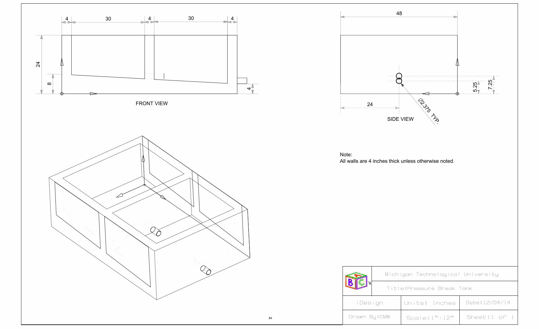
84

85


