Download - Interventional cardiology

Cardiac Angiography
Interventional CardiologyDr. Krisada Sastravaha M.D.
14 December 2012
Balloon Angioplasty
Stent and New Devices
Distal protection and Thrombectomy devices
Vascular Closure Device
Non-coronary Interventions

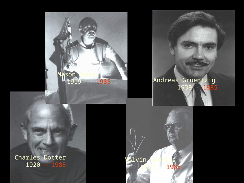
Charles Dotter1920 - 1985

Melvin P. Judkins1922 - 1985

Mason Sones1919 - 1985

Andreas Gruentzig1939 - 1985
Charles Dotter 1920 - 1985
Mason Sones1919 - 1985
Melvin Judkins1922 - 1985
Andreas Gruentzig1939 - 1985

Historic Time Line
Abele,Bentoff,and Myler developed a prototype coronary artery dilator catheter in 1970.
In 1976 Gruentzig miniaturized his peripheral balloon catheter to perform coronary angioplasty in a canine model and later human cadaver experiments.
In May 1977, in San Francisco, Gruentzig,Myler and Hanna performed coronary angioplasty for the first time in living human.

Pre During Post
LAD Lesion

INTERVENTIONAL CARDIOLOGY
INDICATIONS FOR PTCA
ASYMPTOMATIC , MILD SYMPTOMS SUDDEN CARDIAC DEATH SEVERE MYOCARDIAL ISCHEMIA FAILURE MEDICAL THERAPY INTOLERANT OF MEDICAL THERAPY PRIOR TO HIGH RISK SURGERY

INTERVENTIONAL CARDIOLOGY
INDICATIONS FOR PTCA
SYMPTOMATIC UNSTABLE ANGINA PECTORIS FAILED MEDICAL THERAPY LARGE AREA VIABLE MYOCARDIUM RESCUE PTCA PRIMARY PTCA IN ACUTE MI CARDIOGENIC SHOCK
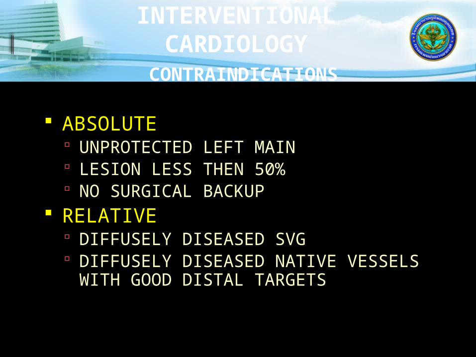
INTERVENTIONAL CARDIOLOGY
CONTRAINDICATIONS
ABSOLUTE UNPROTECTED LEFT MAIN LESION LESS THEN 50% NO SURGICAL BACKUP
RELATIVE DIFFUSELY DISEASED SVG DIFFUSELY DISEASED NATIVE VESSELS
WITH GOOD DISTAL TARGETS

INTERVENTIONAL CARDIOLOGY
CONTRAINDICATIONS
RELATIVE (continued) BLEEDING DIASTHESIS PTCA OF NON-INFARCT VESSEL DURING
PRIMARY PTCA HIGH RISK ANATOMY FOR ABRUPT
CLOSURE SOLE VESSEL SUPPLYING HEART DIABETICS WITH MULTIVESSEL Dx

In the beginning, there were balloons
1977 – 1990 Success rate approached 90% Failures resulting in emergency CABG
about 5% Compared to CABG, equivalent initial
and 5 year outcome, except repeat procedures
Restenosis 20- 25%

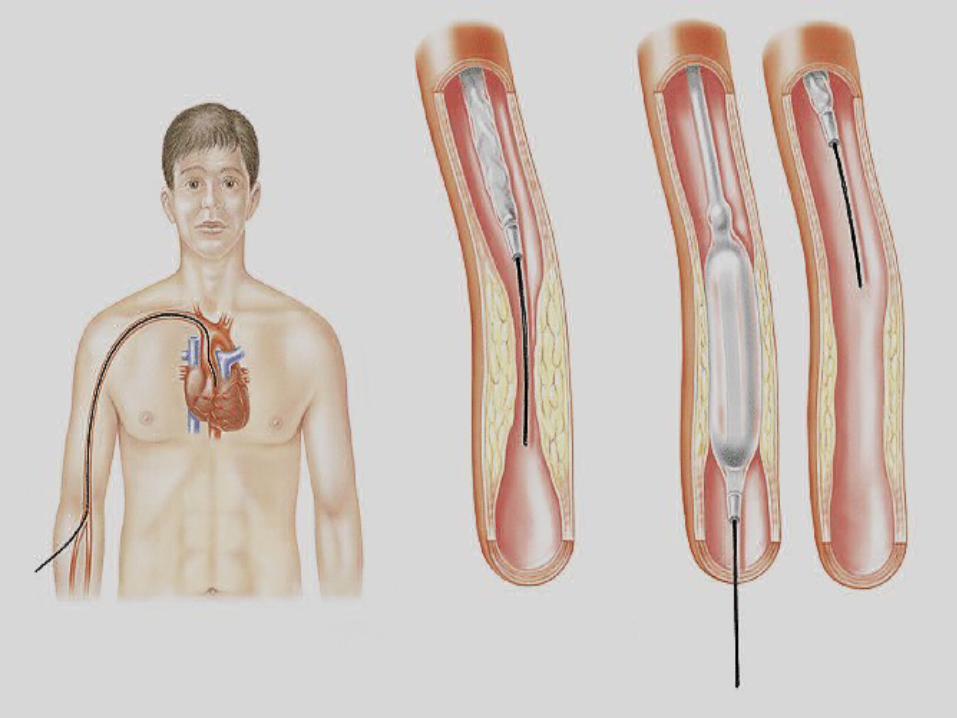
Balloon Angioplasty (PTCA)
Catheter threaded through artery – usually femoral or radial to the aortic root
Guide wire is then inserted into the coronary artery and advanced past the area of stenosis

Balloon Angioplasty (PTCA)
Balloon tipped catheter inserted over guide wire until balloon is in area of stenosis
Balloon is inflated pushing plaque against the vessel wall

Balloon Angioplasty (PTCA)
Balloon inflation causes what has been called a “controlled injury” to the coronary artery.
On balloon deflation, there is some immediate recoil resulting in a loss of
15-30% of the inflated balloon diameter.


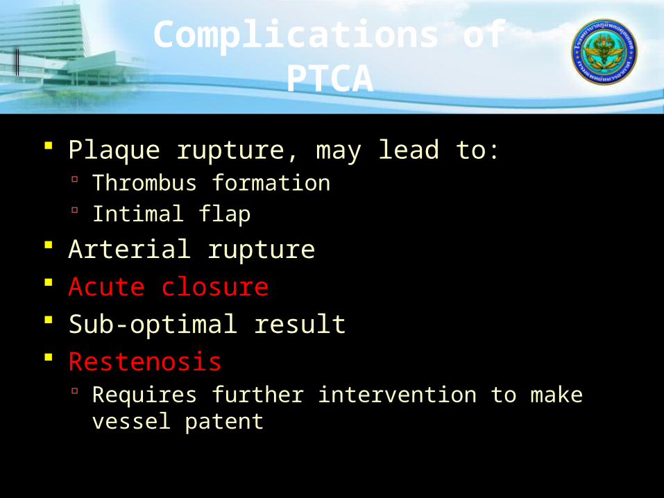
Complications of PTCA
Plaque rupture, may lead to: Thrombus formation Intimal flap
Arterial rupture Acute closure Sub-optimal result Restenosis
Requires further intervention to make vessel patent

INTERVENTIONAL CARDIOLOGY
MAJOR COMPLICATIONS
DEATH (0.5%-1%)
Q-WAVE MYOCARDIAL INFARCTION ( 1%-3%)
EMERGENT SURGERY (1%)

INTERVENTIONAL CARDIOLOGY
PROCEDURAL COMPLICATIONS
ACUTE CLOSURE (4%-8%) SPASM THROMBUS DISECTION EMBOLISM TREATABLE WITH STENTS
PERFORATION
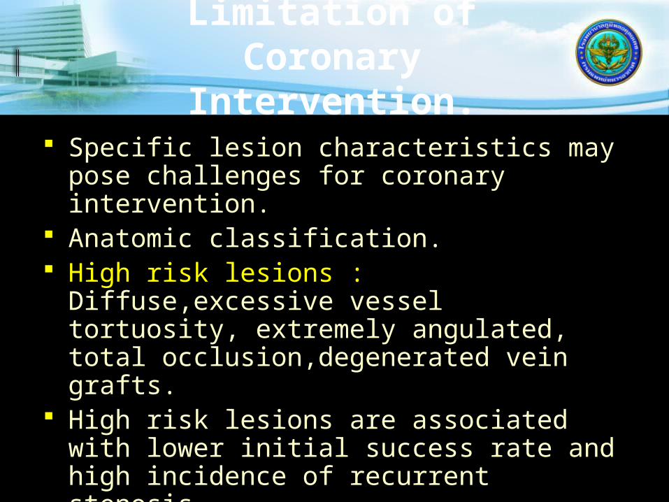
Limitation of Coronary
Intervention. Specific lesion characteristics may pose
challenges for coronary intervention. Anatomic classification. High risk lesions : Diffuse,excessive vessel
tortuosity, extremely angulated, total occlusion,degenerated vein grafts.
High risk lesions are associated with lower initial success rate and high incidence of recurrent stenosis.
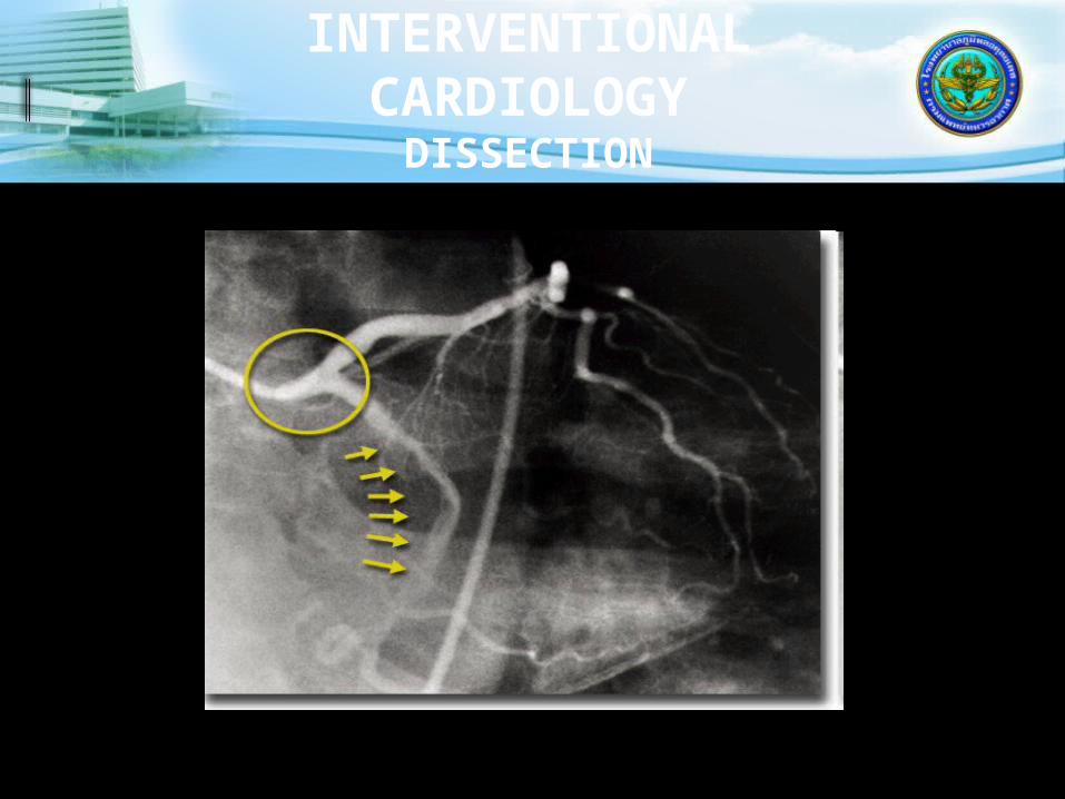
INTERVENTIONAL CARDIOLOGY
DISSECTION

INTERVENTIONAL CARDIOLOGY
ULCERATED PLAQUE
ACC-AHA Coronary Artery Lesion Classification
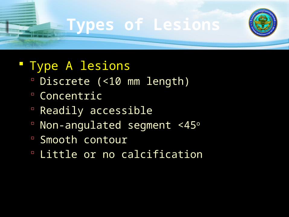
Types of Lesions
Type A lesions Discrete (<10 mm length) Concentric Readily accessible Non-angulated segment <45o
Smooth contour Little or no calcification

Types of Lesions
Type A lesions: Less than totally occlusive Not ostial in location No major branch involvement Absence of thrombus
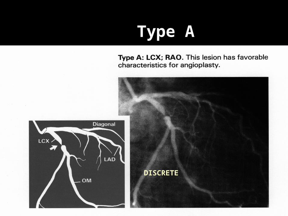
Type A
DISCRETE

Types of Lesions
Type B lesions Tubular (10-20 mm length) Eccentric Moderate tortuosity of proximal segment Moderately angulated segment >45o
<90o Moderate to heavy calcification
Types of Lesions
Type B lesions Total occlusions < 3 months old Ostial in location Bifurcation lesions requiring double
guide wires Some thrombus present
Type B1- B2 lesions
Type B1 lesions have a single adverse B characteristic.
Type B2 lesions have two or more adverse characteristics
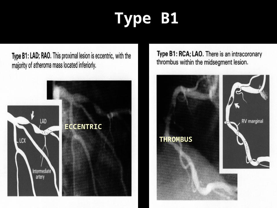
Type B1
ECCENTRIC
THROMBUS

Type B2 (2 Charastics)
ECCENTRIC TUBULAR ECCENTRIC
IRREGULAR
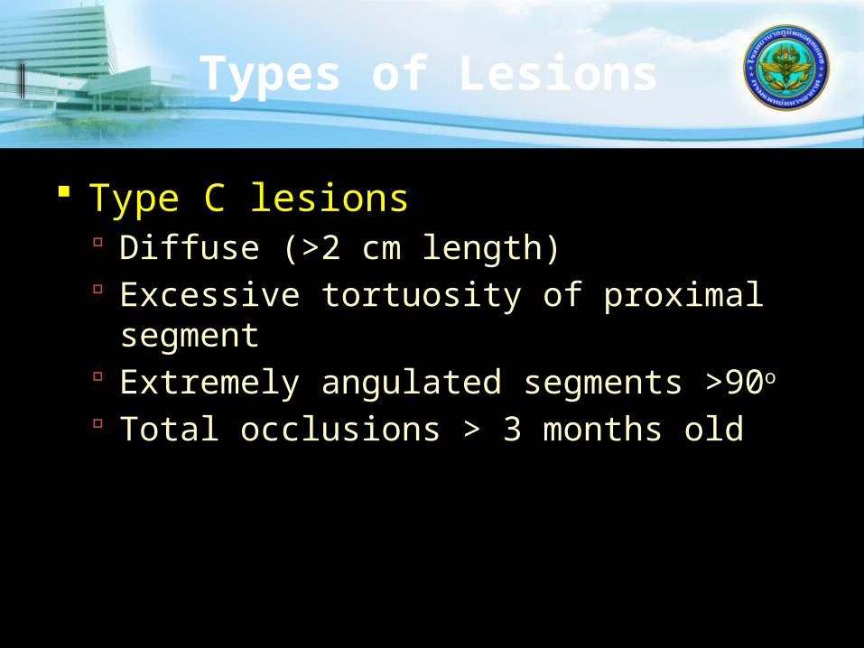
Types of Lesions
Type C lesions Diffuse (>2 cm length) Excessive tortuosity of proximal
segment Extremely angulated segments >90o
Total occlusions > 3 months old

Types of Lesions
Type C lesions Inability to protect major side branches Degenerated vein grafts with friable
lesions
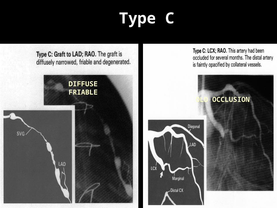
Type C
OLD OCCLUSION
DIFFUSE FRIABLE

IMPLICATIONS
Type A 92% Success, 2% Complications
Type B1 84% Success, 4% Complications
Type B2 76% Success, 10% Complications
Type C 61% Success, 21% Complications

Then came the new devices…
1990 all were investigational Approval 1992 – 1994 Success approached 98% Stents are embraced Need for emergency CABG < 1% Restenosis 10-15%
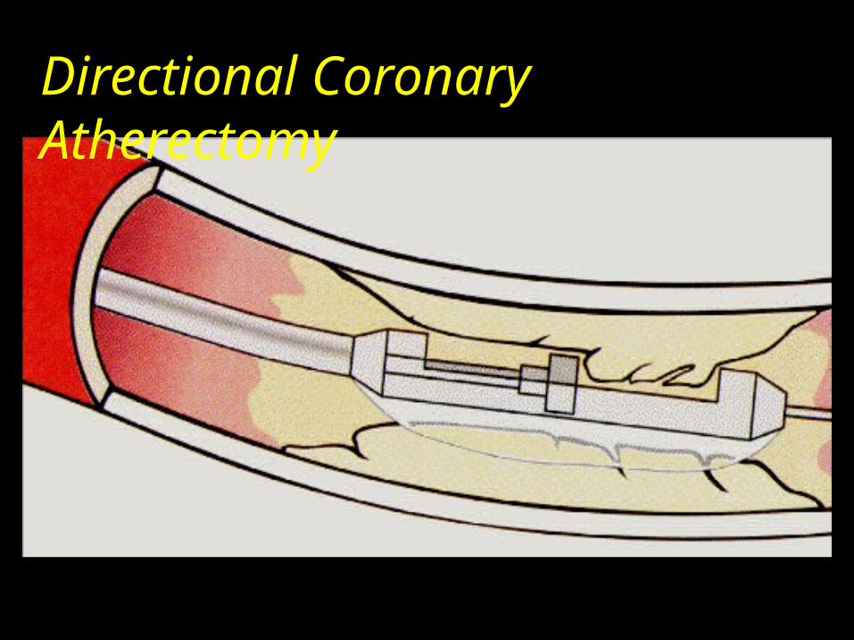
Directional Coronary Atherectomy

Directional Atherectomy

Directional Atherectomy
First alternative to angioplasty. Can be applied selectively to eccentric
disease in the vessel wall, which may be cut out and retrieved.
The cutter rotates at about 2000rpm and as it is advanced it shaves material, which become embedded in the cutting chamber.
Potential concern : Perforation/Dissection. No clear clinical benefit of DCA in
controlled trials : CAVEAT I and II
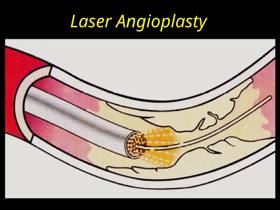
Laser Angioplasty
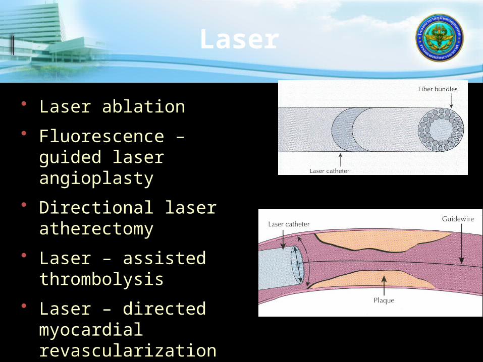
Laser
• Laser ablation
• Fluorescence – guided laser angioplasty
• Directional laser atherectomy
• Laser – assisted thrombolysis
• Laser – directed myocardial revascularization

Laser Angioplasty
Catheter employs buldle of optic fibers delivering ultraviolet laser energy.
Small vessels,thrombotic lesions. Trials : Increased restenosis.
Rotational Atherectomy

04/07/2023
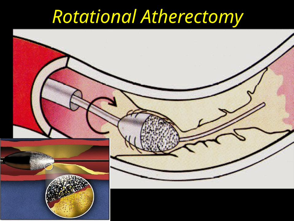
Rotational Atherectomy

Rotational Atherectomy
Diamond chip-covered burr, which rotates at 150,00-200,000rpm.
Calcified lesions especially related to ostia of the vessel.
Lesions that resist balloon dilatation and bifurcation lesions.
Coronary spasm and no reflow ocure with increased frequency.
Trials : ARTIST and ERBAC
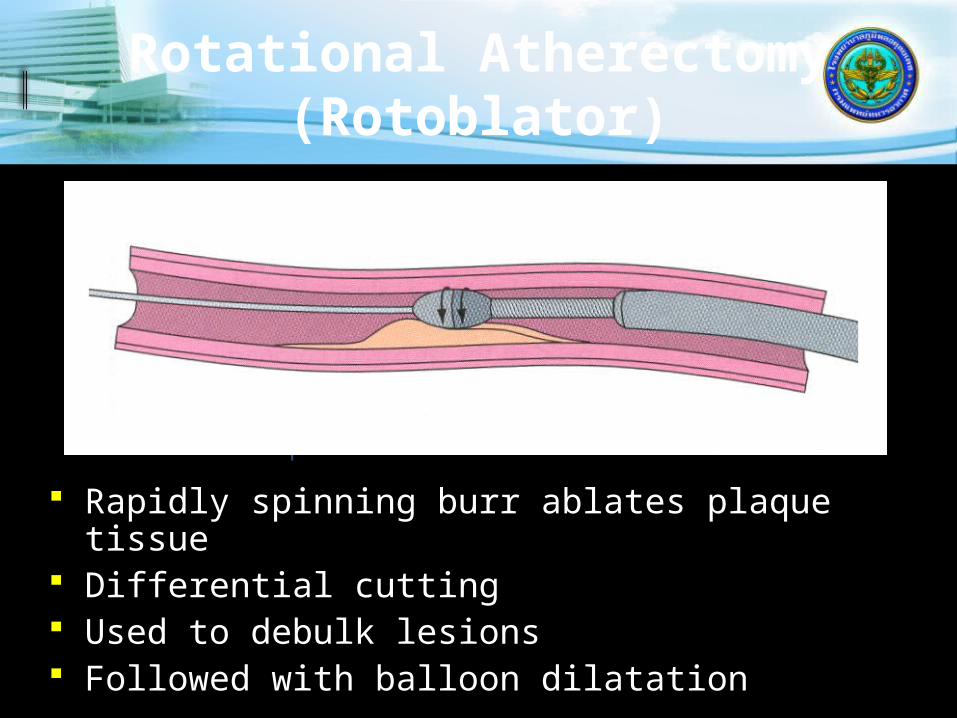
Rotational Atherectomy (Rotoblator)
Rapidly spinning burr ablates plaque tissue Differential cutting Used to debulk lesions Followed with balloon dilatation
.009 Guidewire with .017 spring tip
Elliptical burr coated with diamond chips
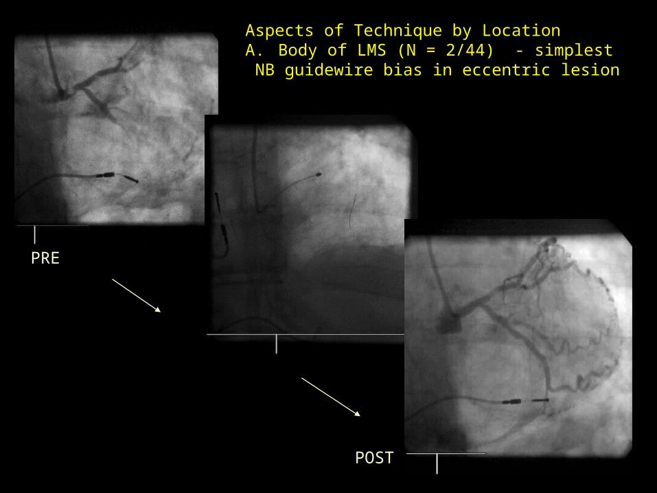
Aspects of Technique by LocationA. Body of LMS (N = 2/44) - simplest NB guidewire bias in eccentric lesion
PRE
POST
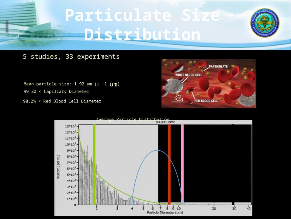
Particulate Size Distribution
5 studies, 33 experiments(Models= Carbon blocks; Thermal injury porcine coronary artery; Diseased cadaver peripheral arteries)
98.2% < Red Blood Cell Diameter
99.97% < 30 um (theoretically the smallest protection device)
99.3% < Capillary Diameter
Mean particle size: 1.92 um (± .1 um)
Average Particle Distribution
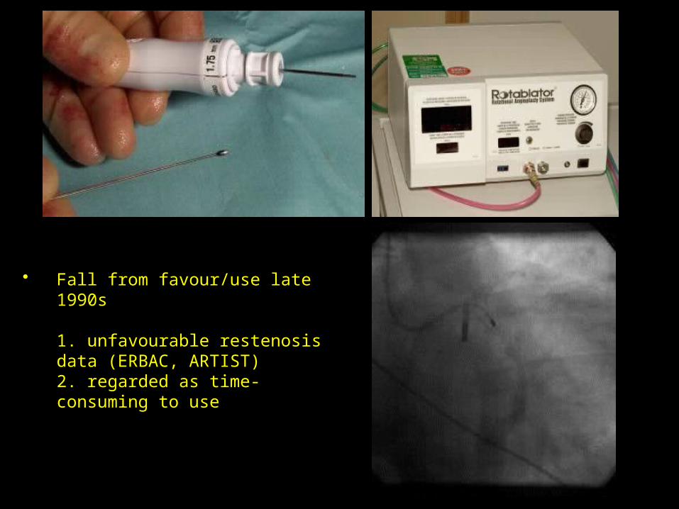
• Fall from favour/use late 1990s
1. unfavourable restenosis data (ERBAC, ARTIST)2. regarded as time-consuming to use

Cutting Balloon
3 to 4 atherotomes mounted on balloon. Capable of protruding outside of the
inflated balloon. Approved for lesions not dilatable by
standered balloon technique. Considerable interest in using for in-stent
restenosis. Little data avialable to suggest
superiorirty over alternative technology.

Cutting Balloon
Advantages Controlled
dissection Non-compliant
balloon
Disadvantages• Crossability • Flexibility
Atherotomes on balloon

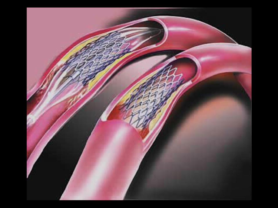
Stent

What is a Stent?
A small tubular mesh usually made of either stainless steel or Nitinol.
Inserted into stenotic arteries to keep the lumen patent often used after PTCA.
Used at various sites including the coronary, renal, carotid and femoral arteries.
Non-arterial uses e.g. in bronchus, trachea, ureter, bile duct.


INTERVENTIONAL CARDIOLOGY
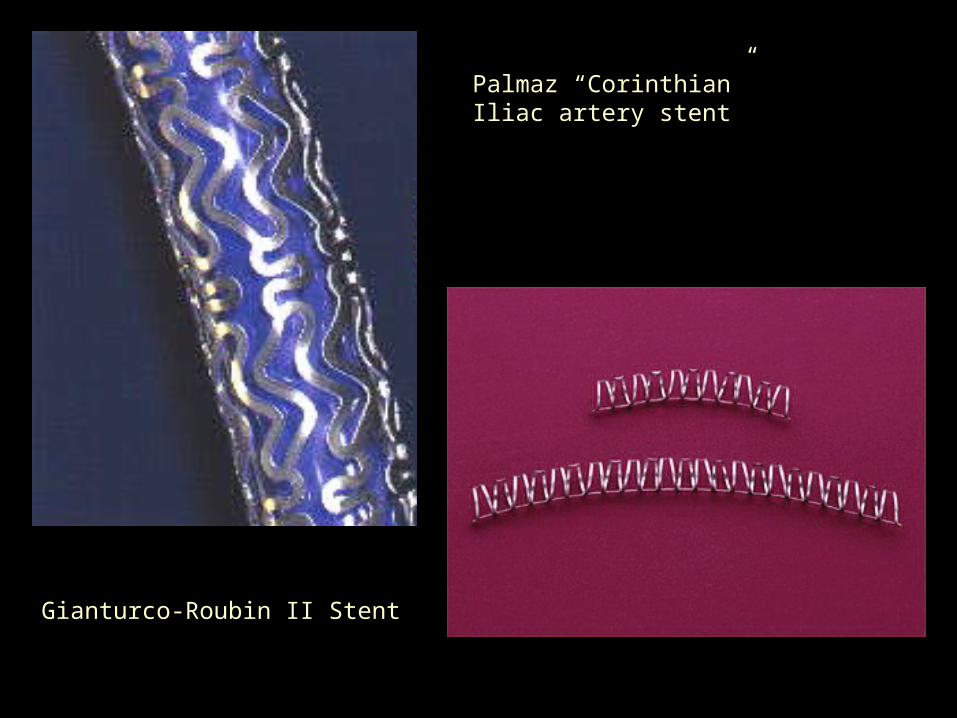
Palmaz “Corinthian” Iliac artery stent
Gianturco-Roubin II Stent

Second Generation Stent
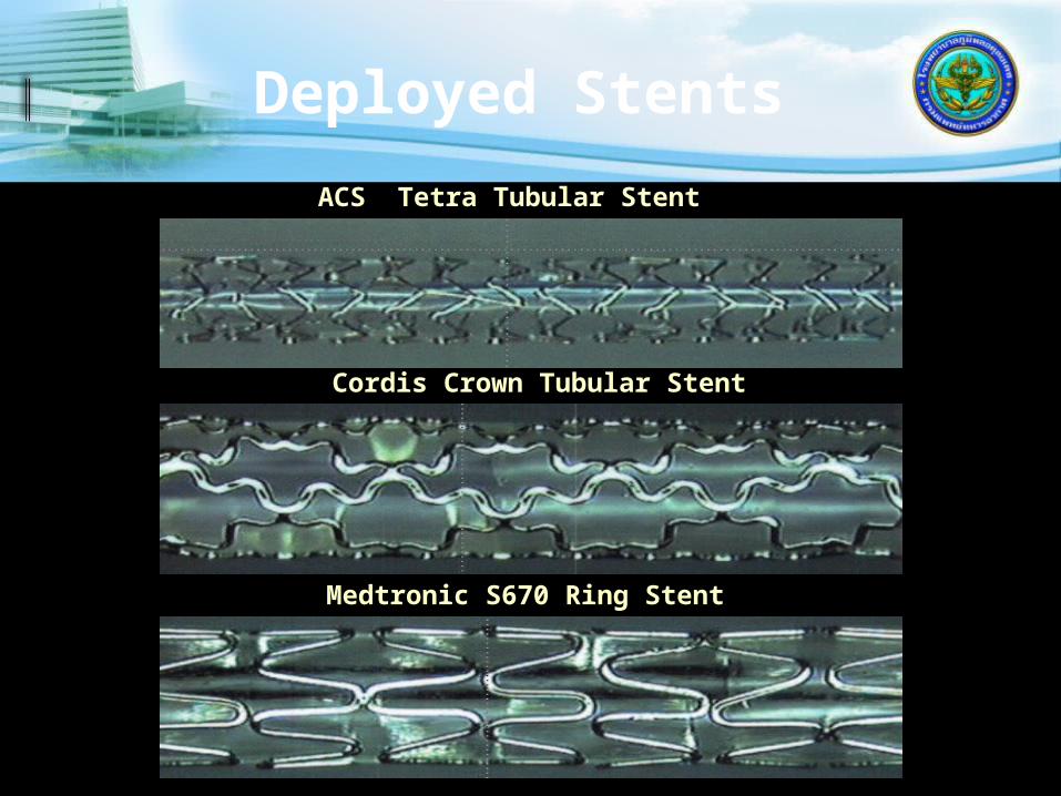
Deployed Stents
Medtronic S670 Ring Stent
Cordis Crown Tubular Stent
ACS Tetra Tubular Stent

Stenting
Most PCI are performed with the use of stents
Wire mesh coil pushed against vessel wall to prevent closure of the vessel post procedure
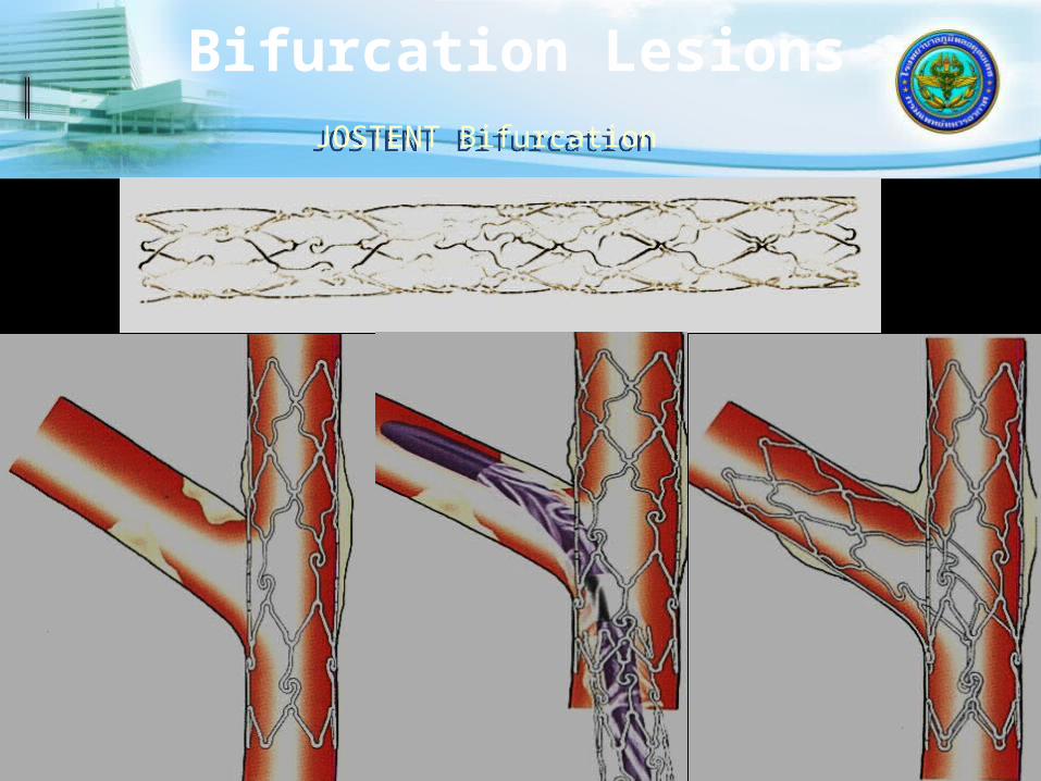
Bifurcation LesionsJOSTENT BifurcationJOSTENT Bifurcation
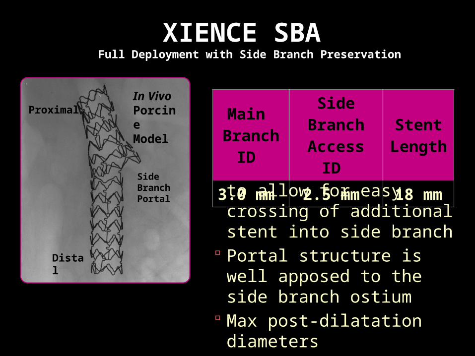
XIENCE SBA Full Deployment with Side Branch Preservation
XIENCE SBA is designed to allow for easy crossing of additional stent into side branch
Portal structure is well apposed to the side branch ostium
Max post-dilatation diameters
3.75 mm main branch 3.0 mm side branch
Main Branch ID
Side Branch Access ID
Stent Length
3.0 mm 2.5 mm 18 mm
Distal
Proximal
Side Branch Portal
In Vivo Porcine Model

XIENCE SBA Delivery SystemBased Upon MULTI-LINK FRONTIER Concept
Dual lumen tip
Joining mandrel inserted through OTW inner member
Main Branch (RX)
Side Branch (OTW)
Design Features ObjectivesSingle Tip Delivery • Ease of use
• Avoid wire wrap• 7F guide catheter
compatible
Simultaneous Balloon Deployment
• Deploy stent quickly• Minimize plaque shift
Side Branch Portal • Provide ostial scaffolding

Dedicated XIENCEXIENCE Technology Dedicated to Side Branch
Access
Side Branch Access and Preservation
XIENCE Technology
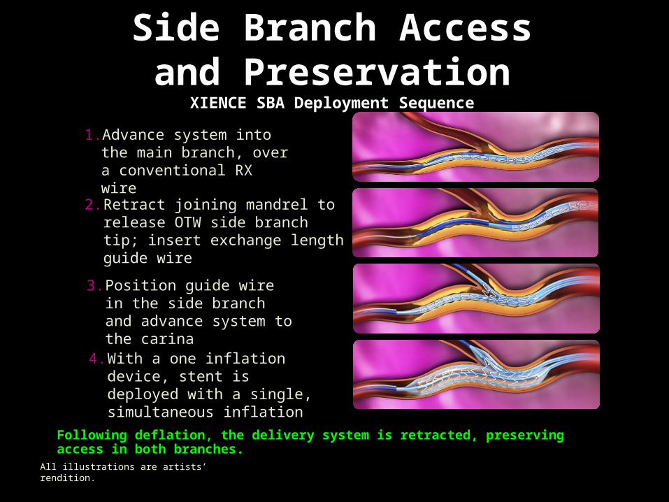
Following deflation, the delivery system is retracted, preserving access in both branches.
XIENCE SBA is currently a pipeline product at Abbott Vascular. Not available for sale. Information contained herein for presentation outside of the U.S. and outside Japan. Not to be reproduced, distributed, or excerpted.
3. Position guide wire in the side branch and advance system to the carina
1. Advance system into the main branch, over a conventional RX wire
2. Retract joining mandrel to release OTW side branch tip; insert exchange length guide wire
4. With a one inflation device, stent is deployed with a single, simultaneous inflation
Side Branch Access and Preservation
XIENCE SBA Deployment Sequence
All illustrations are artists’ rendition.

Side Branch Access and Preservation
XIENCE SBA is Designed to Treat Lesions at Bifurcations
Standard workhorses may show a malapposed lateral wall and train-wrecking at and around the side branch after post-deployment balloon dilatation
XIENCE SBA shows complete lateral wall apposition and even stent coverage around the side branch
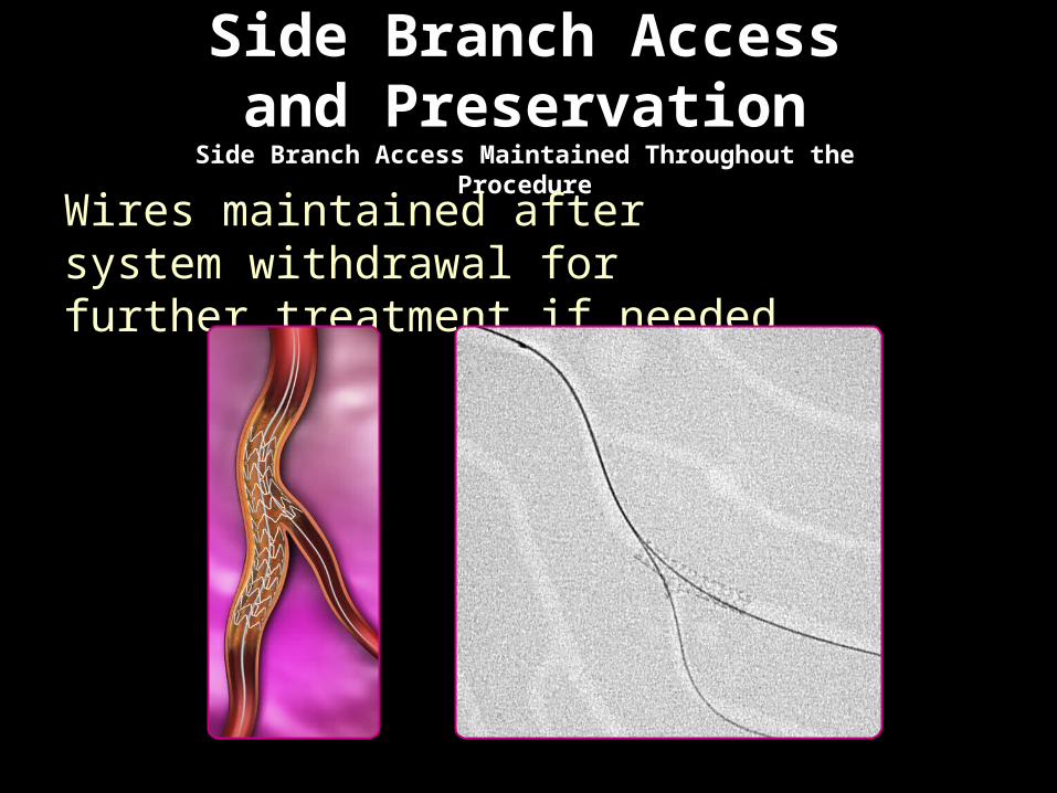
Side Branch Access and Preservation
Side Branch Access Maintained Throughout the Procedure
Wires maintained after system withdrawal for further treatment if needed
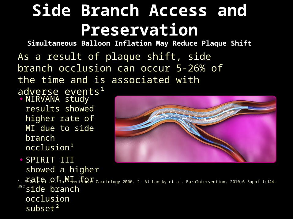
Side Branch Access and Preservation
Simultaneous Balloon Inflation May Reduce Plaque Shift
As a result of plaque shift, side branch occlusion can occur 5-26% of the time and is associated with adverse events¹
1. S Garg et al. Interventional Cardiology 2006. 2. AJ Lansky et al. EuroIntervention. 2010;6 Suppl J:J44-J52.
• NIRVANA study results showed higher rate of MI due to side branch occlusion¹
• SPIRIT III showed a higher rate of MI for side branch occlusion subset²
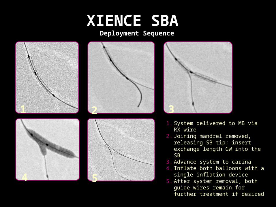
XIENCE SBA Deployment Sequence
1 2 3
4 5
1. System delivered to MB via RX wire2. Joining mandrel removed, releasing
SB tip; insert exchange length GW into the SB
3. Advance system to carina4. Inflate both balloons with a single
inflation device5. After system removal, both guide
wires remain for further treatment if desired

Coronary PerforationJOSTENT Stent GraftJOSTENT Stent Graft
• Ultra thin layer of expandable PTFE is placed between two stents, welded at it’s ends
• effectively seals off the vessel wall for perforations, aneurysms and can be beneficial in life saving situations
• Ultra thin layer of expandable PTFE is placed between two stents, welded at it’s ends
• effectively seals off the vessel wall for perforations, aneurysms and can be beneficial in life saving situations
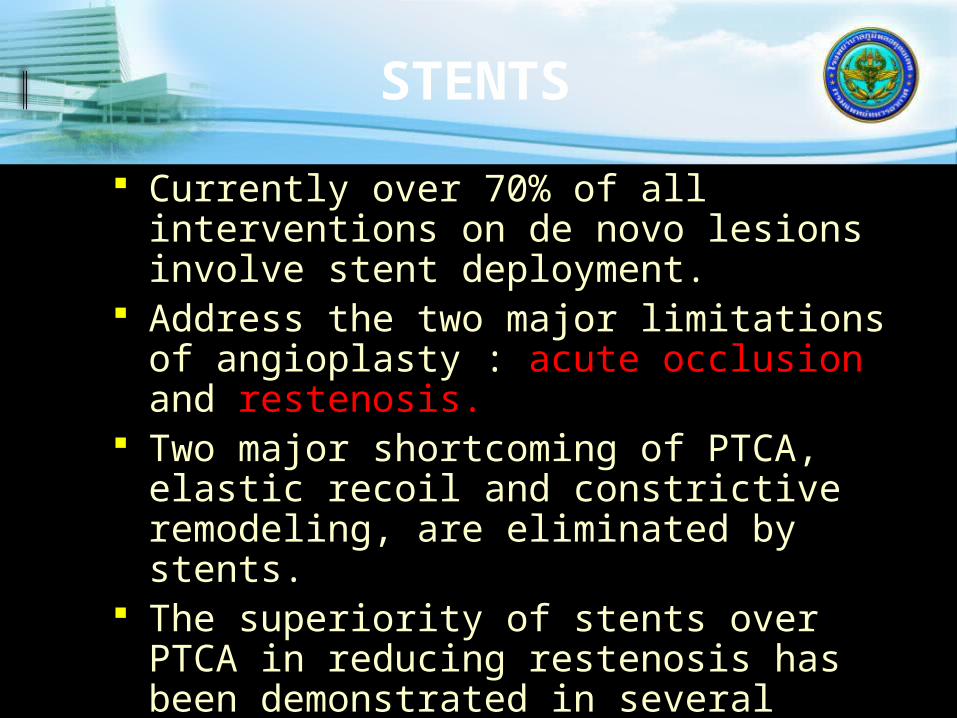
STENTS
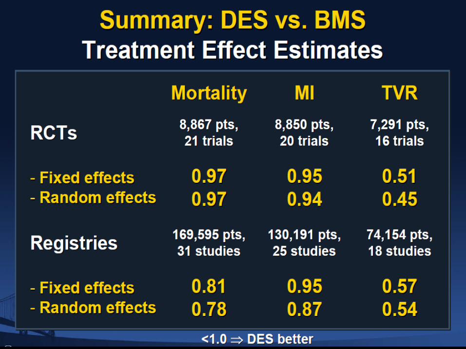
Currently over 70% of all interventions on de novo lesions involve stent deployment.
Address the two major limitations of angioplasty : acute occlusion and restenosis.
Two major shortcoming of PTCA, elastic recoil and constrictive remodeling, are eliminated by stents.
The superiority of stents over PTCA in reducing restenosis has been demonstrated in several clinical trials:
STRESS - 29%Vs 43% BENESTENT - 22% Vs
32% REST -
18% Vs 32%

Restenosis
7 Days 7 Days 90 Days90 Days

In-stent restenosis is a hyper-proliferative disorder.
The Problem
Restenosis
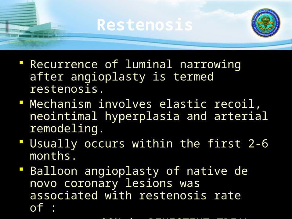
Recurrence of luminal narrowing after angioplasty is termed restenosis.
Mechanism involves elastic recoil, neointimal hyperplasia and arterial remodeling.
Usually occurs within the first 2-6 months. Balloon angioplasty of native de novo
coronary lesions was associated with restenosis rate of :
- 32% in BENESTENT TRIAL - 42% in STRESS TRIAL - 57% in CAVEAT TRIAL.

Stent Failure
Restenosis20-30 %
7 Days 7 Days 90 Days90 Days

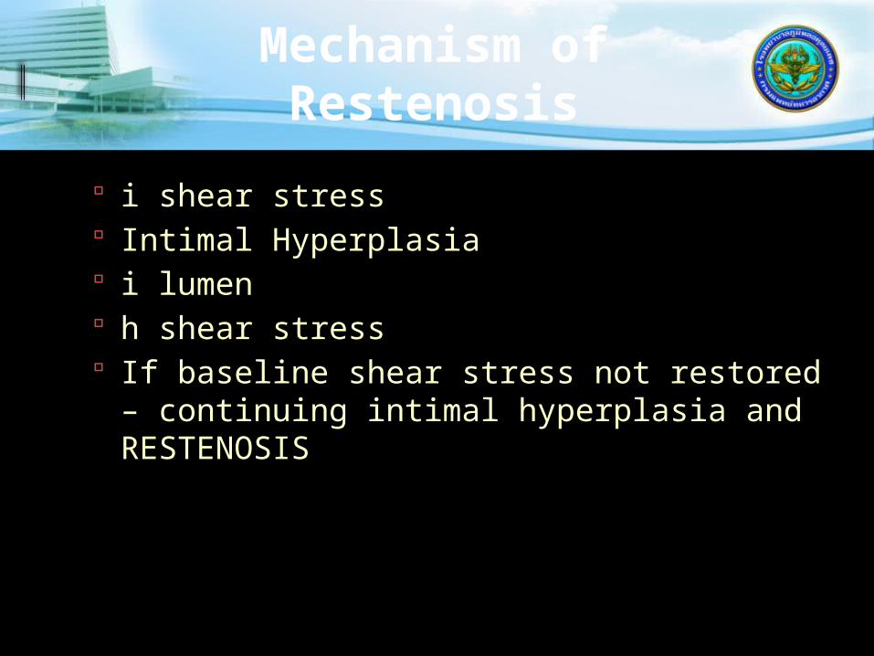
Mechanism of Restenosis
i shear stress Intimal Hyperplasia i lumen h shear stress If baseline shear stress not restored –
continuing intimal hyperplasia and RESTENOSIS

Factors Which Contribute to In-stent
Restenosis Thrombus/platelet/fibrin adherence to
stent struts. Metabolic disorder/smoking/atherogenic
diet. Small lumen diameter. Stress concentration at end of stent. Flow disturbance within stented region.
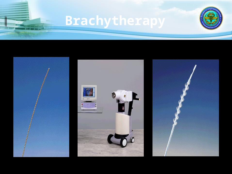
Brachytherapy
04/07/2023Cardiac Angiography
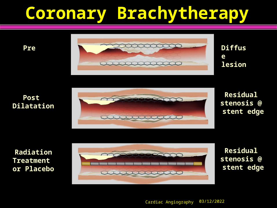
Coronary Brachytherapy
Pre
Post Dilatation
RadiationTreatment or Placebo
Diffuse lesion
Residual stenosis @ stent edge
Residual stenosis @ stent edge

04/07/2023Cardiac Angiography

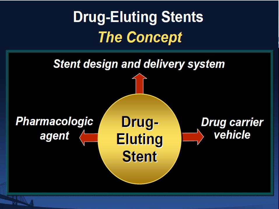


Absorb BVS: The 4th Revolution in Percutaneous
Coronary Intervention
1977Balloon Angioplasty
(PTCA)
BareMetal Stents
(BMS)
Coronary Drug
Eluting Stents (DES)
AbsorbBioresorbable
Vascular Scaffold (BVS)
1977 1988 2001 Today
After implant.
After resorption.
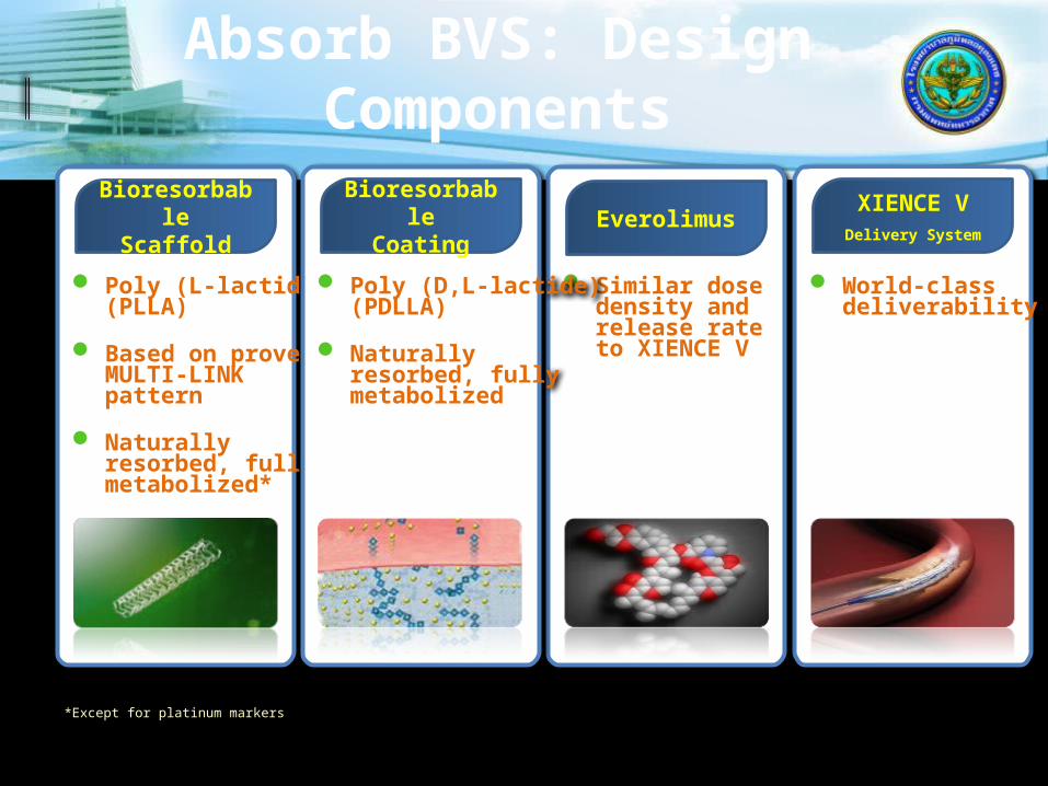
Poly (L-lactide)(PLLA)
Based on provenMULTI-LINK pattern
Naturally resorbed, fully metabolized*
World-class deliverability
Similar dosedensity andrelease rateto XIENCE V
Poly (D,L-lactide)(PDLLA)
Naturally resorbed, fully metabolized
Absorb BVS: Design Components
Bioresorbable
Scaffold
Bioresorbable
CoatingEverolimus
XIENCE VDelivery System
*Except for platinum markers

Description of the ABSORB Device
4. Description & usage of study device
ABSORB
Bioresorbable Vascular Scaffold
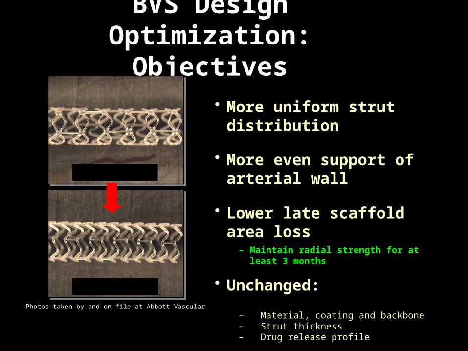
BVS Design Optimization:
Objectives
Cohort A
Cohort B Photos taken by and on file at Abbott Vascular.
• More uniform strut distribution
• More even support of arterial wall
• Lower late scaffold area loss– Maintain radial strength for at least 3 months
• Unchanged:
– Material, coating and backbone– Strut thickness– Drug release profile
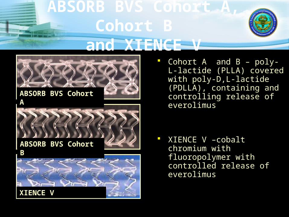
ABSORB BVS Cohort A, Cohort B and XIENCE V
Cohort A and B – poly-L-lactide (PLLA) covered with poly-D,L-lactide (PDLLA), containing and controlling release of everolimus
XIENCE V –cobalt chromium with fluoropolymer with controlled release of everolimus
ABSORB BVS Cohort A
ABSORB BVS Cohort B
XIENCE V
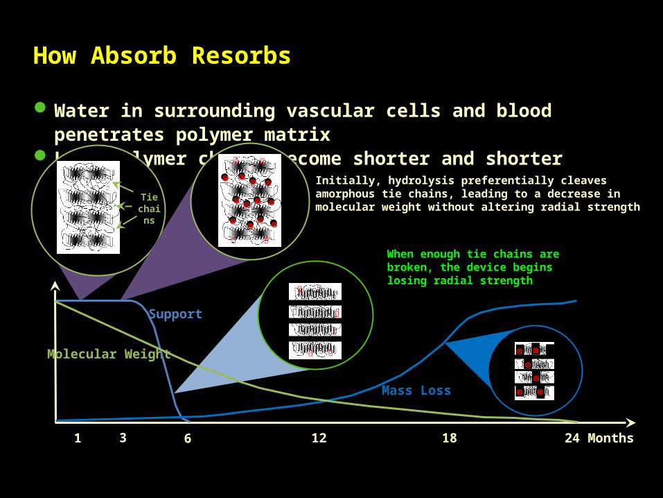
Water in surrounding vascular cells and blood penetrates polymer matrix Long polymer chains become shorter and shorter
1 3 6 24 Months
Support
Mass Loss
Tie chains
Initially, hydrolysis preferentially cleaves amorphous tie chains, leading to a decrease in molecular weight without altering radial strength
When enough tie chains are broken, the device begins losing radial strength
Molecular Weight
12 18
How Absorb Resorbs
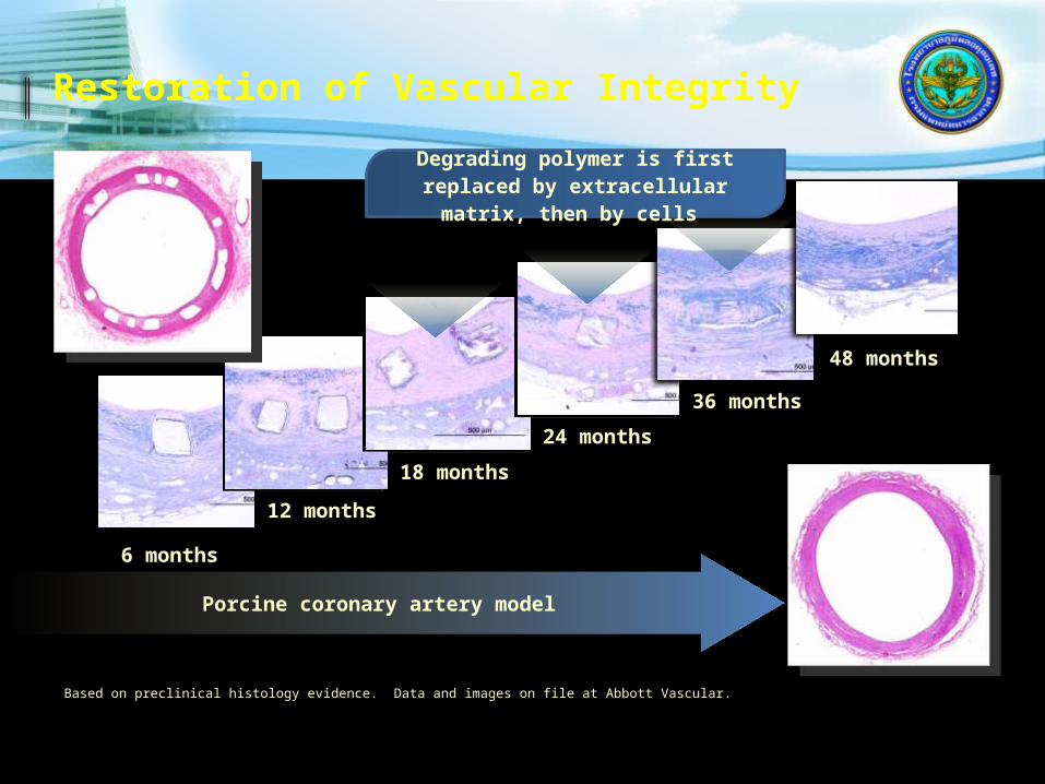
6 months
12 months
18 months
24 months
36 months
48 months
Porcine coronary artery model
Degrading polymer is first replaced by extracellular matrix,
then by cells
Restoration of Vascular Integrity
Based on preclinical histology evidence. Data and images on file at Abbott Vascular.
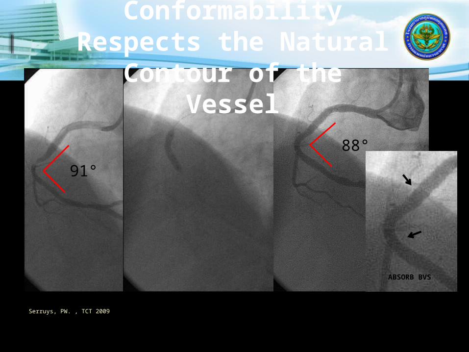
91°
88°
ABSORB BVS
Absorb BVS Conformability
Respects the Natural Contour of the Vessel
Serruys, PW. , TCT 2009
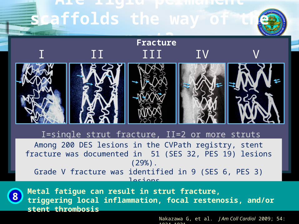
Are rigid permanent scaffolds the way of the
past? Fracture
I=single strut fracture, II=2 or more struts fracture without deformation, III=2 or more struts fracture with deformation, IV=multiple fractures with acquired transection without gap,
V=multiple fractures with acquired transections with gap
Among 200 DES lesions in the CVPath registry, stent fracture was documented in 51 (SES 32, PES 19) lesions (29%).
Grade V fracture was identified in 9 (SES 6, PES 3) lesions.
I II III IV V
Nakazawa G, et al. J Am Coll Cardiol 2009; 54: 1924-1931.
88Metal fatigue can result in strut fracture, triggering local inflammation, focal restenosis, and/or stent thrombosis

Periprocedural complications
In 1% to 3%, procedure is complicated in hospital by a severe adverse event, while in the remainder, the procedure is unsuccessful either because a guidewire or device could not be delivered across the lesion or because the criteria for success are not met.
Difficult angioplasty Scenarios
Chronic total occlusion. Calcified lesion. Ostial lesion. Bifurcation lesion. Long lesion. Bypass conduit.

Severe Adverse Events
Death (0.5% to 1%) Q wave myocardial infarction (1% to3%) Need for emergent CABG (less than 1%) Acute Occlusion . Dissection. Thrombosis, spasm, embolism. Perforation. Significant CPK elevation.

No-Reflow Phenomenon
Distal embolization of thrombus and/or atheromatous debris .
Thrombotic lesions, degenerated vein grafts are high risk .
Thrombectomy Devices
To treat thrombus containing lesion and prevent distal embolization

What happens if you just stent thrombus
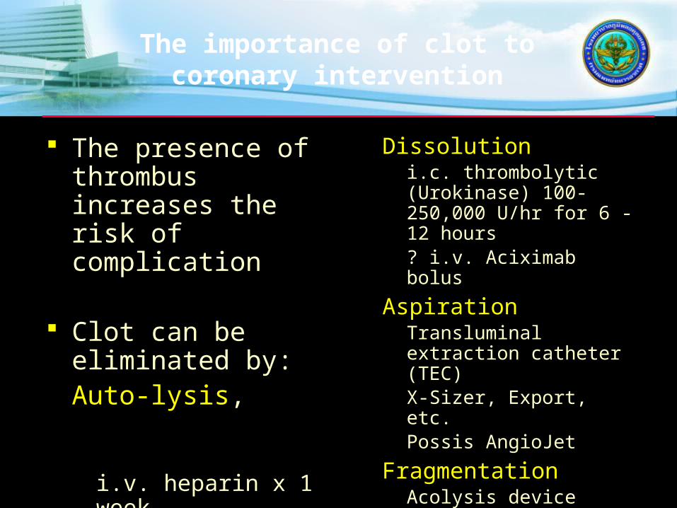
The importance of clot to coronary intervention
The presence of thrombus increases the risk of complication
Clot can be eliminated by:Auto-lysis, particularly if facilitated by
i.v. heparin x 1 weekp.o. coumadin x 6 weeks
Dissolutioni.c. thrombolytic (Urokinase) 100-250,000 U/hr for 6 - 12 hours? i.v. Aciximab bolus
AspirationTransluminal extraction catheter (TEC)X-Sizer, Export, etc. Possis AngioJet
FragmentationAcolysis device (ultrasound)OmniSonics

Intra-coronary thrombolysis

Transluminal Extraction Catheter

TEC Device
Transluminal extraction catheter. 750rpm. Aspirate debris as it is advanced through
the vessel. The device appear most suitable thrombus
laden vessels. Distal embolization, no reflow and CPK
elevation. No significant long term benefit.

Transluminal Extraction Catheter (TEC)
Large guide Low efficiency Low success High complic.
ev3 Inc.
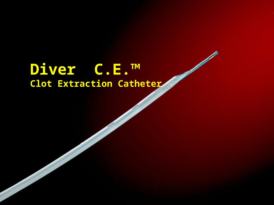
Diver C.E.™ Clot Extraction Catheter
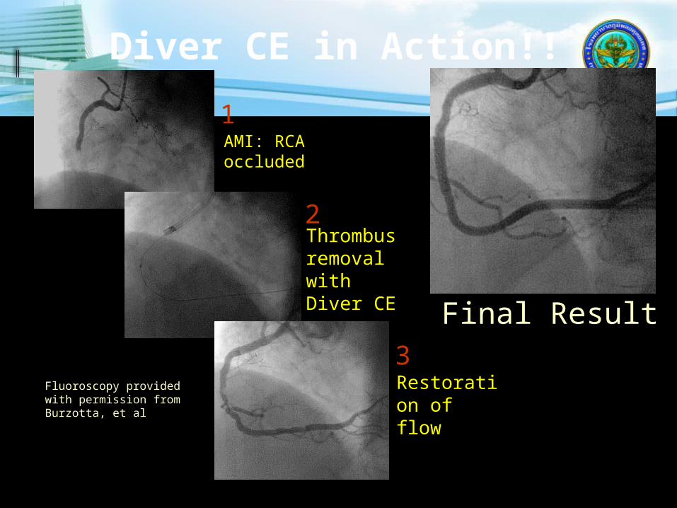
Diver CE in Action!!
AMI: RCA occluded
Thrombus removal with Diver CE
Restoration of flow
Final Result
1
2
3Fluoroscopy provided with permission from Burzotta, et al
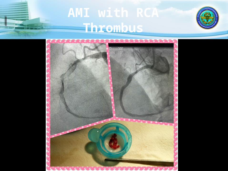
AMI with RCA Thrombus
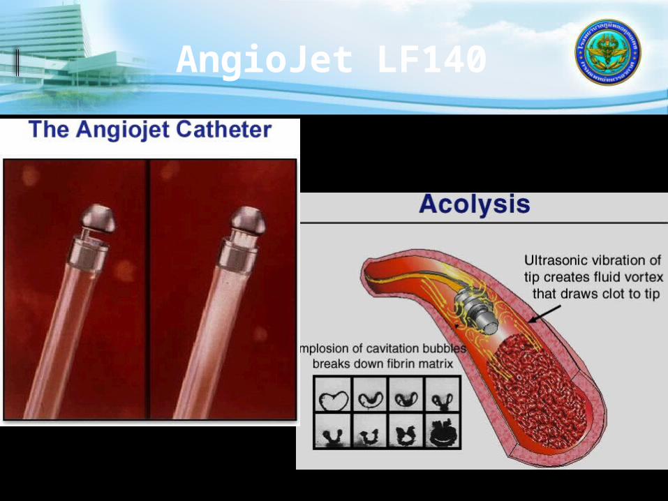
AngioJet LF140
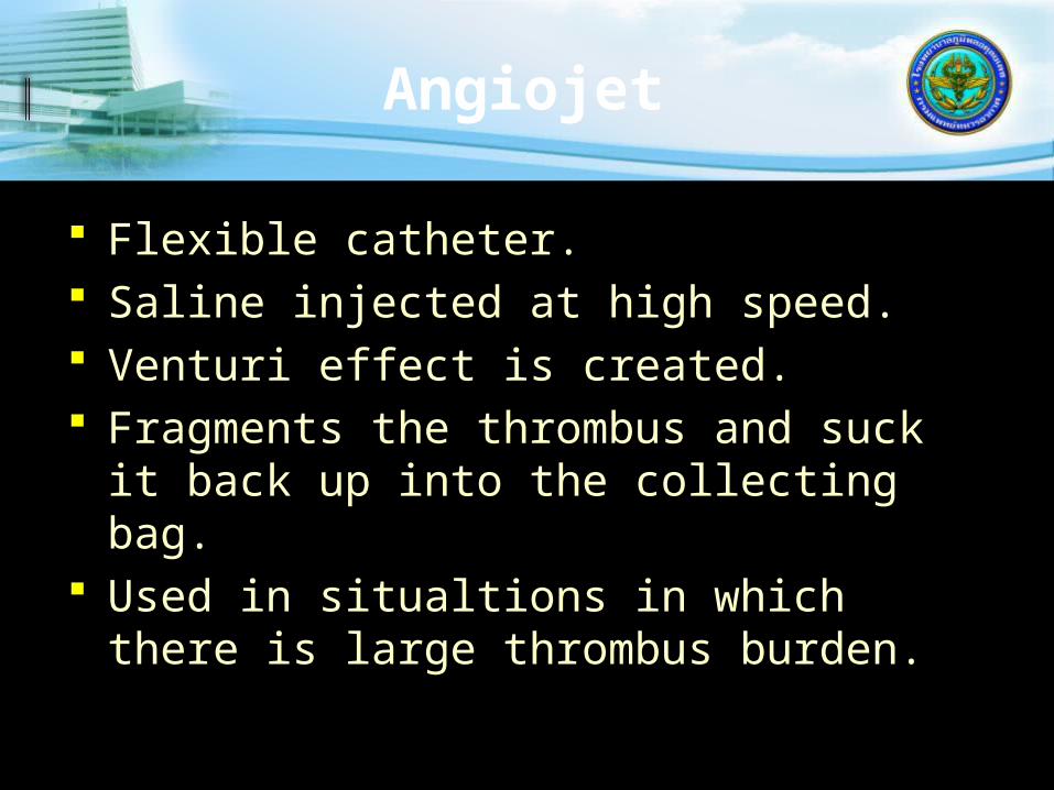
Angiojet
Flexible catheter. Saline injected at high speed. Venturi effect is created. Fragments the thrombus and suck it
back up into the collecting bag. Used in situaltions in which there is
large thrombus burden.

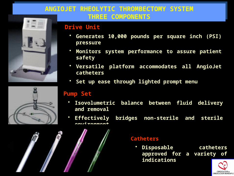
ANGIOJET RHEOLYTIC THROMBECTOMY SYSTEMTHREE COMPONENTS
ANGIOJET RHEOLYTIC THROMBECTOMY SYSTEMTHREE COMPONENTS
Drive Unit • Generates 10,000 pounds per square inch (PSI)
pressure
• Monitors system performance to assure patient safety
• Versatile platform accommodates all AngioJet catheters
• Set up ease through lighted prompt menu
Pump Set • Isovolumetric balance between fluid delivery and
removal
• Effectively bridges non-sterile and sterile environment
Catheters
• Disposable catheters approved for a variety of indications

Angiojet of SVG Thrombus
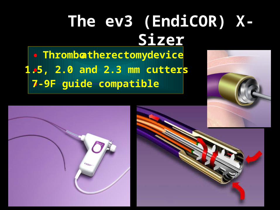
The ev3 (EndiCOR) X-Sizer
• Thrombo atherectomy device
• 1.5, 2.0 and 2.3 mm cutters
• 7-9F guide compatible
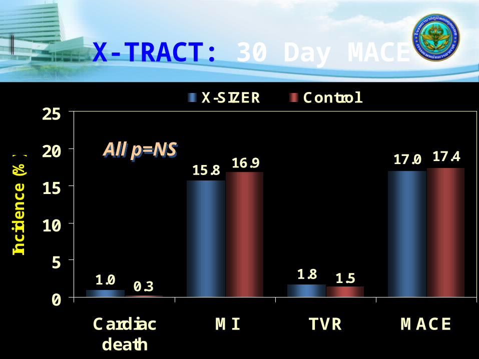
X-TRACT: 30 Day MACE
17.0 17.4
1.0
15.8
1.8 1.5
16.9
0.30
5
10
15
20
25
Cardiacdeath
MI TVR MACE
Inc
ide
nc
e (
%)
X-SIZER Control
All p=NSAll p=NS

5.76.7
8.18.1
0
5
10
15
Large MI Death orlarge MI
Inci
den
ce (
%)
X-SIZER Control
X-TRACT: Impact of Thrombus
4.94.1
10.2 10.7
0
5
10
15
Large MI Death orlarge MI
Inc
ide
nc
e (
%)
X-SIZER Control
Thrombus pre (n=450)Thrombus pre (n=450)
60%60%
No thrombus pre (n=253)No thrombus pre (n=253)
54%54% 30%30% 17%17%
Distal Protection Devices

Distal Protection Device Concepts
Filter Device
Balloon Occlusion Device
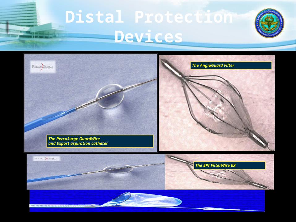
Distal Protection Devices
The EPI FilterWire EX
The PercuSurge GuardWireand Export aspiration catheter
The AngioGuard Filter
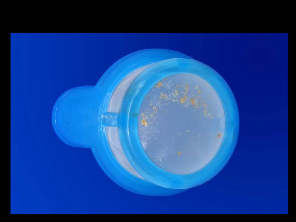
Distal Protection
“The Most Frequent Complication of Distal Protection Devices is Distal Embolization”
(Device-, Operator-/Technique-, Lesion-related)
The 2 Principles of Distal Protection:
„You need distal embolizationto benefit from distal protection“


Limitations of Angiography

INTERVENTIONAL CARDIOLOGY
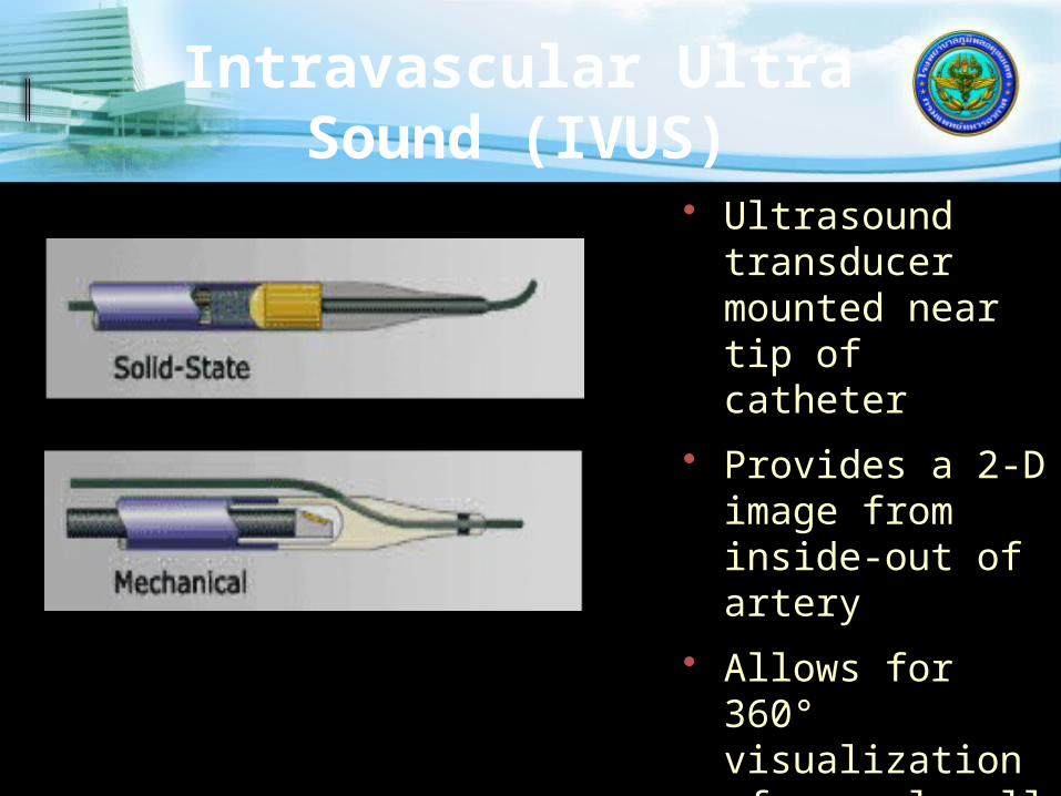
Intravascular Ultra Sound (IVUS)
• Ultrasound transducer mounted near tip of catheter
• Provides a 2-D image from inside-out of artery
• Allows for 360° visualization of vessel wall
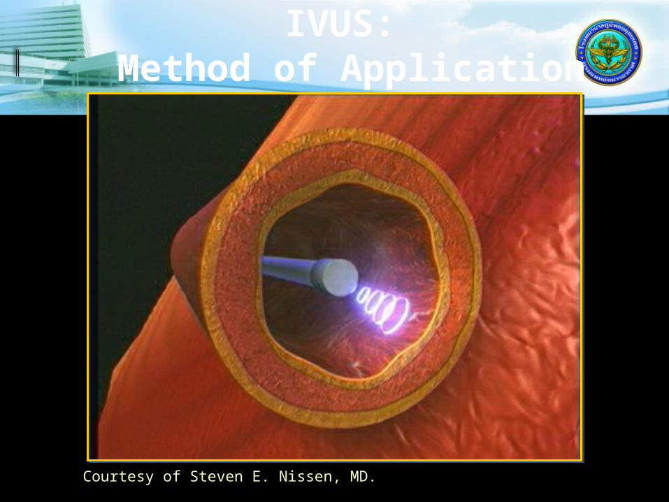
IVUS: Method of Application
Courtesy of Steven E. Nissen, MD.
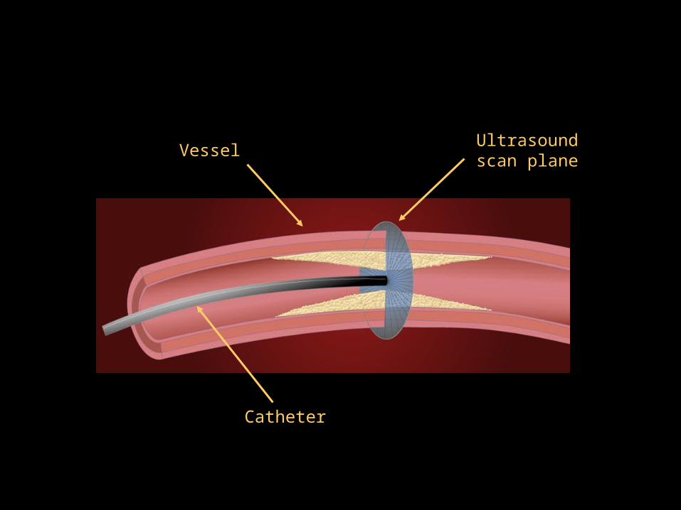
Ultrasound scan plane
Vessel
Catheter

High frequency sound waves echo off vessel walls and are sent back to system
System electronics process the signal
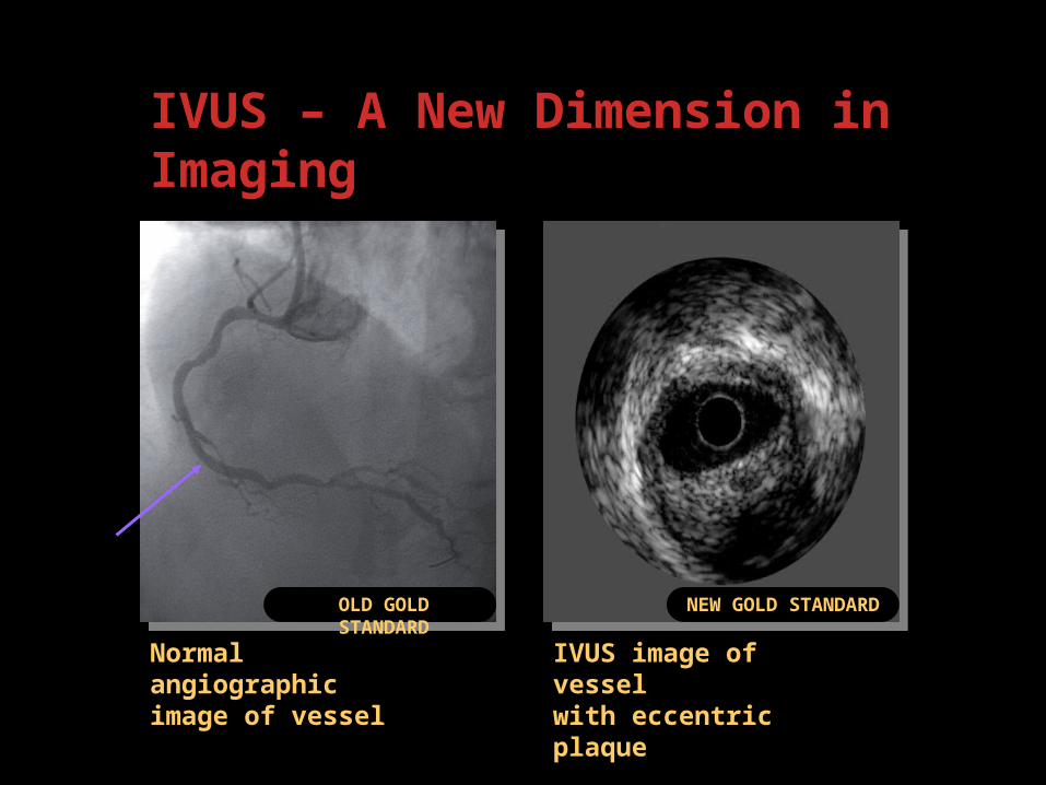
Normal angiographic image of vessel
IVUS – A New Dimension in Imaging
IVUS image of vessel with eccentric plaque
OLD GOLD STANDARD
NEW GOLD STANDARD
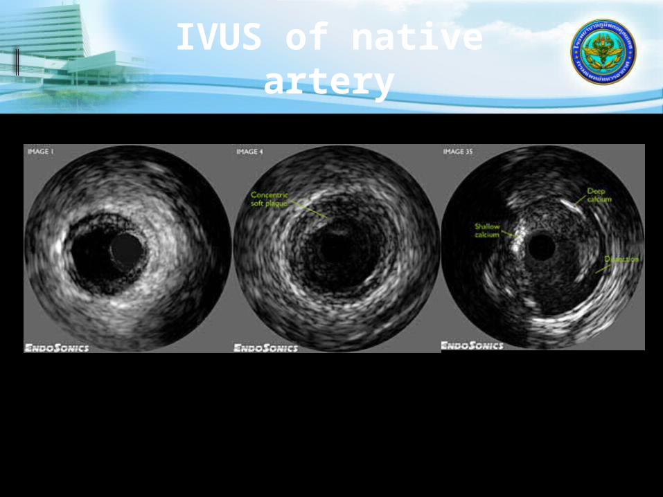
IVUS of native artery

IVUS of Stent
IVUS=intravascular ultrasoundNissen S, Yock P. Circulation 2001; 103: 604–616
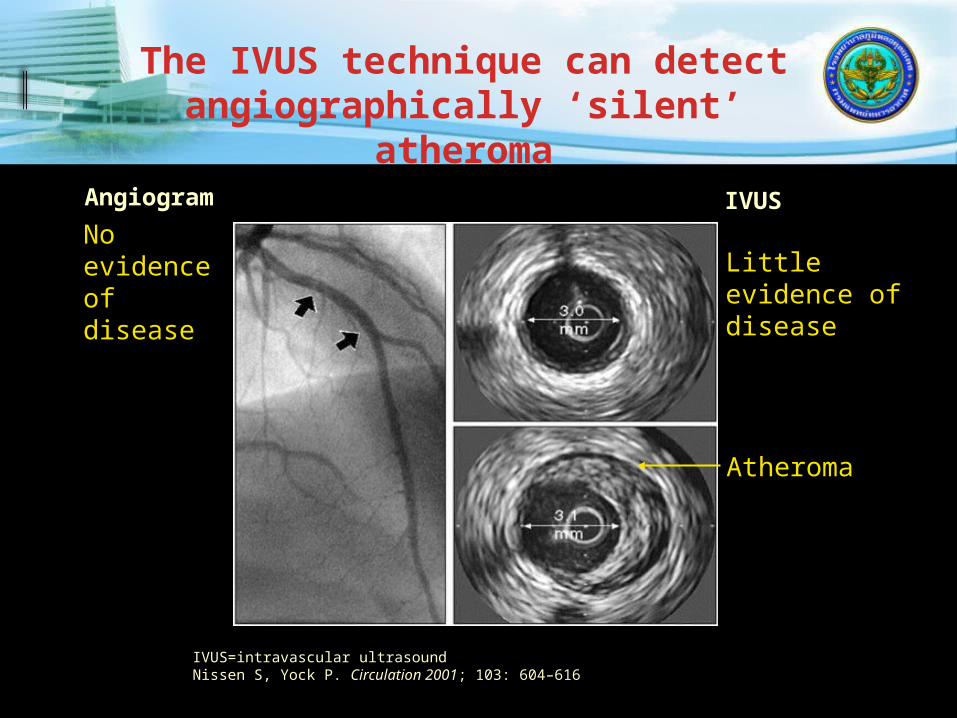
Angiogram IVUS
Little evidence of disease
Atheroma
No evidence of disease
The IVUS technique can detect angiographically ‘silent’
atheroma

Courtesy of Steven E. Nissen, MD.
IVUS Imaging of Intimal Plaque
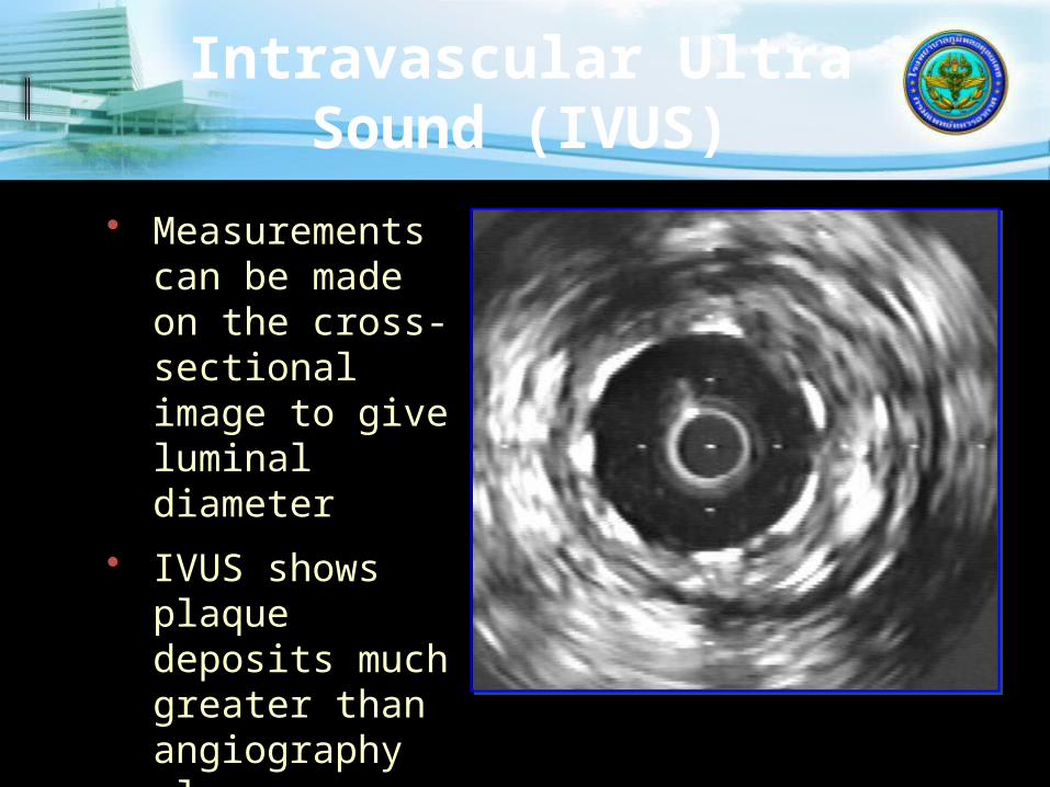
Intravascular Ultra Sound (IVUS)
• Measurements can be made on the cross-sectional image to give luminal diameter
• IVUS shows plaque deposits much greater than angiography alone

Incomplete Stent Apposition

INTERVENTIONAL CARDIOLOGY
LIMITATIONS OF ANGIOGRAPHY

Virtual Histology

Interventional Technique
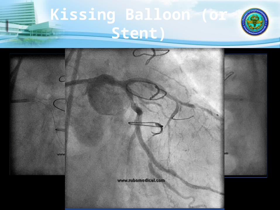
Kissing Balloon (or Stent)

Anchor Balloonfor CTO
Fujita et al Catheterization and Cardiovascular Interventions 59:482–488 (2003)

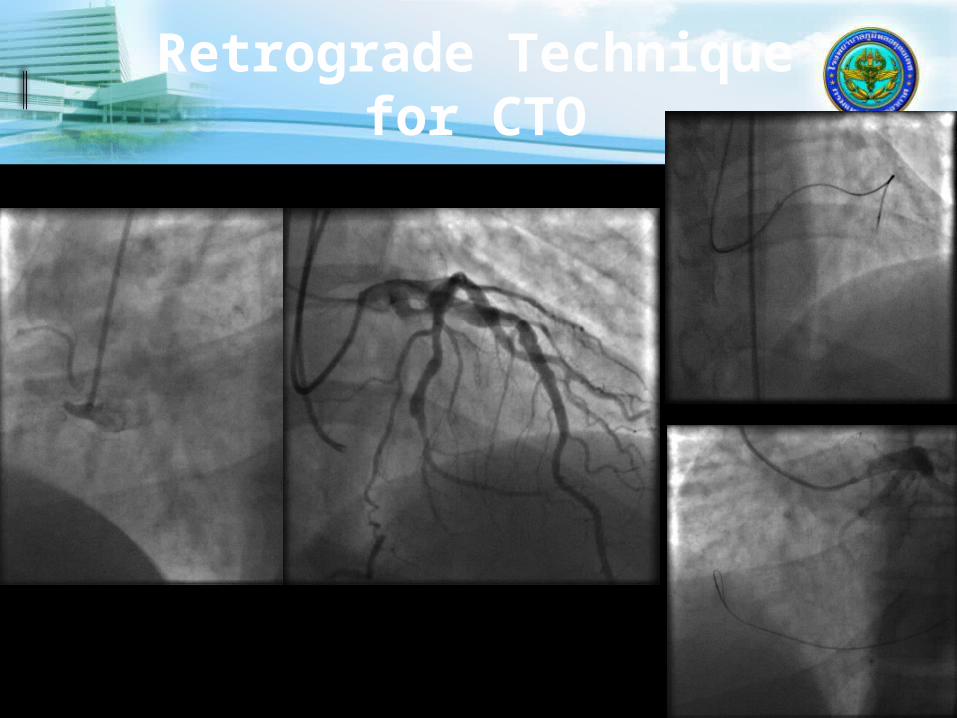
Retrograde Technique for CTO
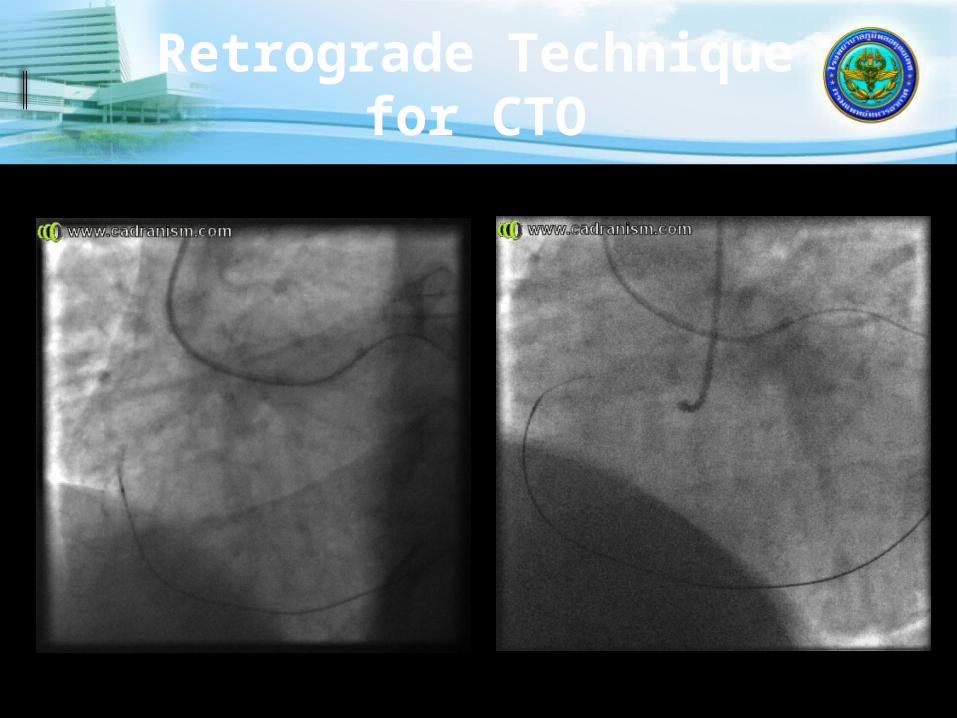
Retrograde Technique for CTO

Retrograde Technique for CTO

Retrograde Technique for CTO
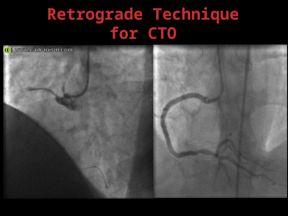
Retrograde Technique for CTO

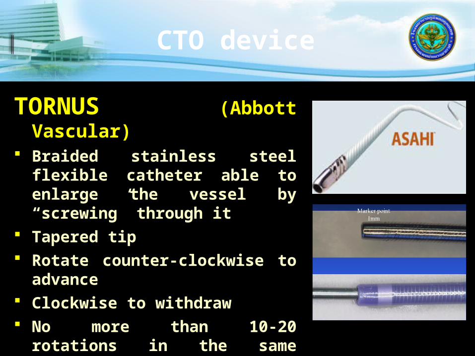
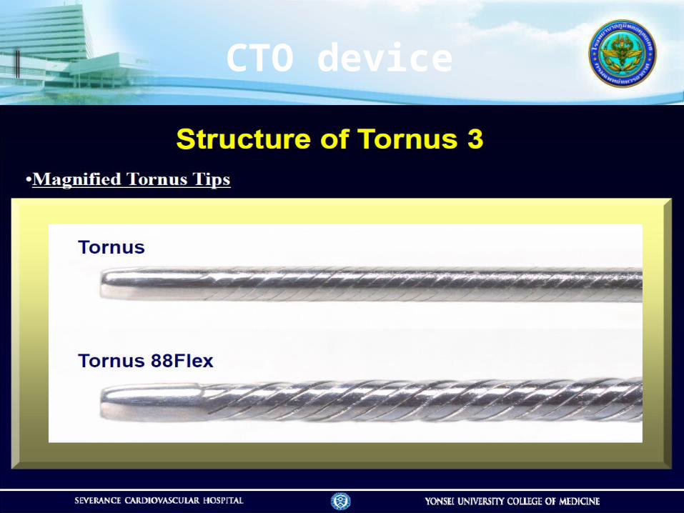
TORNUS (Abbott Vascular)
Braided stainless steel flexible catheter able to enlarge the vessel by “screwing” through it
Tapered tip Rotate counter-clockwise to
advance Clockwise to withdraw No more than 10-20
rotations in the same direction
CTO device
CTO device

CTO device

Corsair (Vascular
Perspectives) Tapered soft tip Hydrophilic coating ASAHI brand braiding pattern, consisting of 8 thinner wires wound with 2 larger ones
Advancement: hold a torque device at all times to avoid ASAHI Corsair
and the guide wire to be rotated together Image the Corsair tip under fluoroscopy to make sure
that the tip is not trapped by the lesion avoid torque accumulation - limit the rotation to 10
times in one direction. To continue advancing ASAHI Corsair, rotate the opposite direction
Rotate the Corsair during removal into the guide

Non-coronary interventions
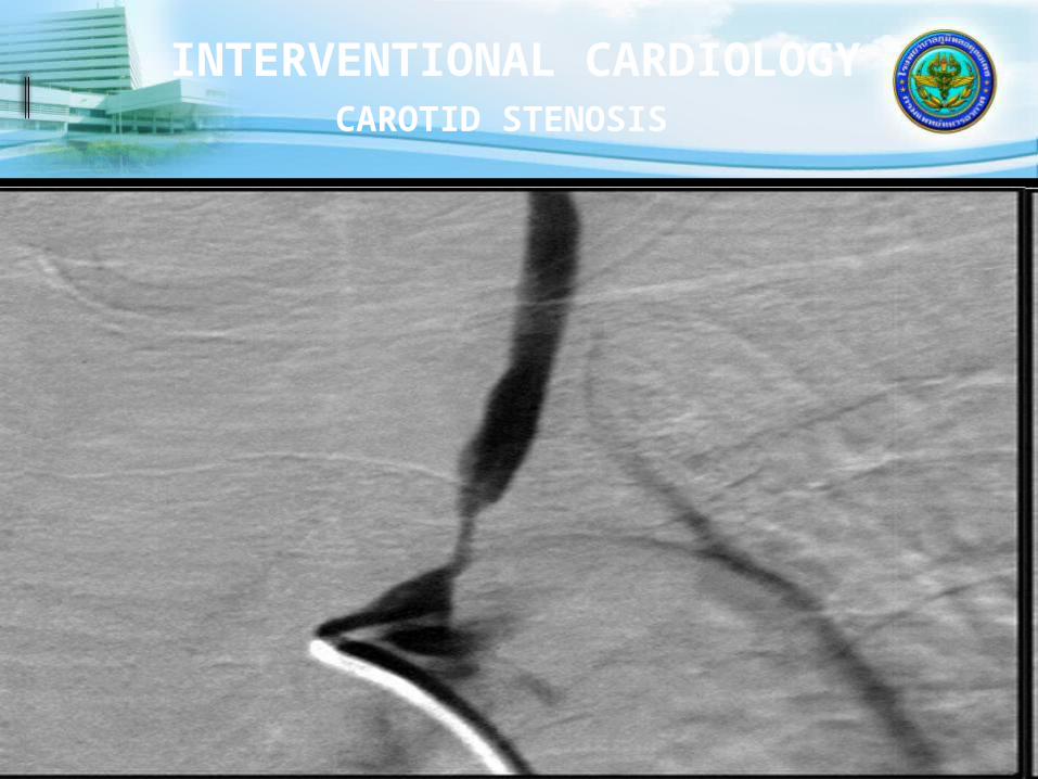
INTERVENTIONAL CARDIOLOGY
CAROTID STENOSIS

INTERVENTIONAL CARDIOLOGY
CAROTID STENOSIS AFTER STENTING
INTERVENTIONAL CARDIOLOGY
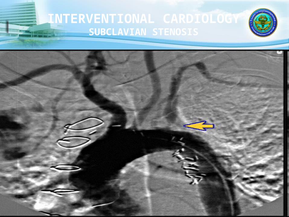
SUBCLAVIAN STENOSIS

INTERVENTIONAL CARDIOLOGY
SUBCLAVIAN STENOSIS POST PTA

Balloon AngioplastySUMMARY
RAPIDLY GROWING FIELD PTCA IDEAL FOR SINGLE VESSEL AND 2-
VESSEL DISEASE WITHOUT PROXIMAL LAD INVOLVEMENT
STENTS USED IN 90% PTCA CASES Drug-eluting stents in 80%
RESTENOSIS LESS OF A LIMITING FACTOR
NON-CORONARY PTA EXPANDING

Mitral Valvuloplasty Aortic Valvuloplasty
Percutaneous Valvuloplasty

INTERVENTIONAL CARDIOLOGY
MITRAL VALVULOPLASTY
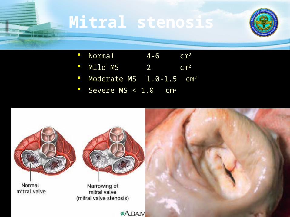
Mitral stenosis
Normal 4-6 cm2
Mild MS 2 cm2
Moderate MS 1.0-1.5 cm2
Severe MS < 1.0 cm2

MS :PTMC
Wilkin Score-Leaflet mobility-Valvular thickening-Subvalvular thickening-Valvular calcification

Aortic Stenosis
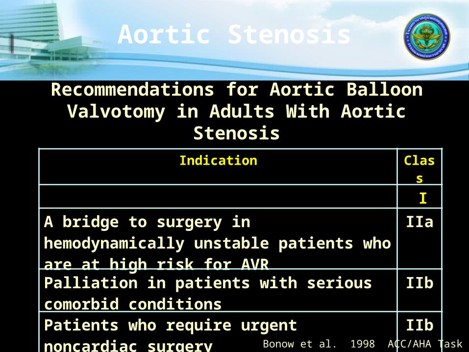
Recommendations for Aortic Balloon Valvotomy in Adults With Aortic Stenosis
Indication Class
I
A bridge to surgery in hemodynamically unstable patients who are at high risk for AVR
IIa
Palliation in patients with serious comorbid conditions
IIb
Patients who require urgent noncardiac surgery
IIb
As an alternative to AVR IIIBonow et al. 1998 ACC/AHA Task Force

Balloon Aortic Valvuloplasty?
Benefits Yes, but transient
Risks Yes
Alternatives AVR
Alters natural history but also carries risk
Percutaneous AVR ? The future? The only role for BAV ?
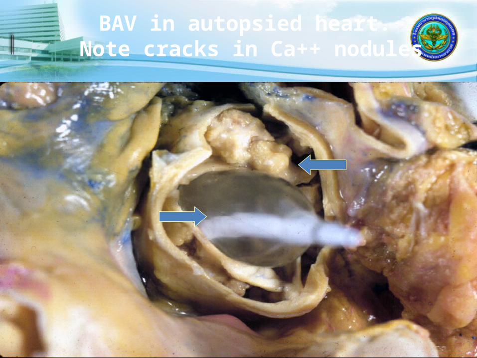
BAV in autopsied heart. Note cracks in Ca++ nodules
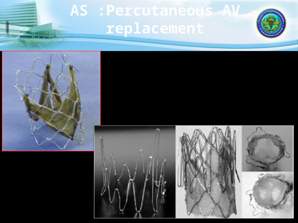
AS :Percutaneous AV replacement
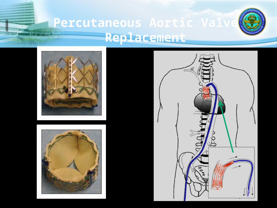
Percutaneous Aortic Valve Replacement

Percutaneous Aortic Valve Replacement


New TAVI valves are coming to the market in a few year’s time
Boston Sci.Lotus™
HLT
Direct FlowSaint JudePortico™
SymetisACCURATE
JenaValve
MedtronicEngager
EdwardsSapien
MedtronicCoreValve
Next Gen.MedtronicCoreValve
EdwardsSapien XT
EdwardsSapien XT
Today Tomorrow
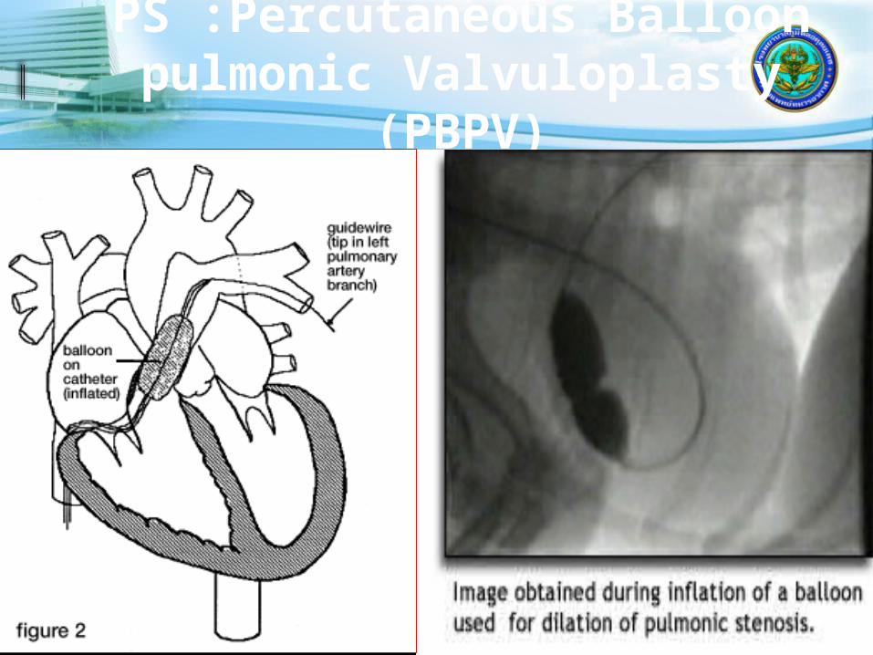
PS :Percutaneous Balloon pulmonic Valvuloplasty
(PBPV)

Transcatheter Pulmonary Valve Replacement
Bonhoeffer Lancet 2000;356:1403-5
Melody® Valve SapienTM Valve
IDE Trial Began 1/2007
HDE Approval 1/2010
IDE Trial Began 1/08
COMPASSION -Recruiting

Atrial Septal Defect Closure
Atrial septal defect – DevicesAmplatzer Helex
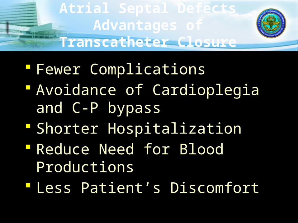
Atrial Septal DefectsAdvantages of
Transcatheter Closure
Fewer Complications Avoidance of Cardioplegia and C-
P bypass Shorter Hospitalization Reduce Need for Blood
Productions Less Patient’s Discomfort

Lock Clamshell CardioSEAL
AmplatzerDas Angel Wings
STARFlex
ASDOS Umbrella

Amplatzer ASD Closure Device

Atrial Septal Defect Closure
Amplatzer Septal Occluder Self-expandable, double disc Nitinol wire mesh, short connecting
waist Discs and waist filled with polyester
fabric

Cera
ASD Closure Device
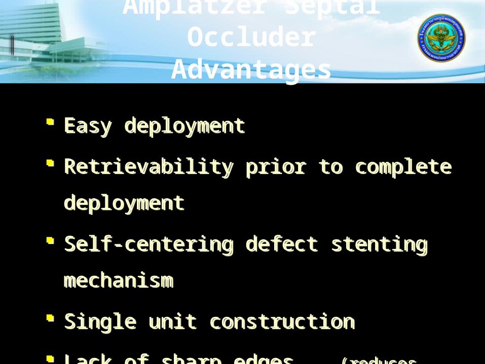
Amplatzer Septal Occluder
Advantages
Easy deployment
Retrievability prior to complete
deployment
Self-centering defect stenting
mechanism
Single unit construction
Lack of sharp edges (reduces cardiac
perforation)
Can close larger defects with less rim
Easy deployment
Retrievability prior to complete
deployment
Self-centering defect stenting
mechanism
Single unit construction
Lack of sharp edges (reduces cardiac
perforation)
Can close larger defects with less rim

Atrial Septal Defect Closure
Atrial septal defect – Cribriform device
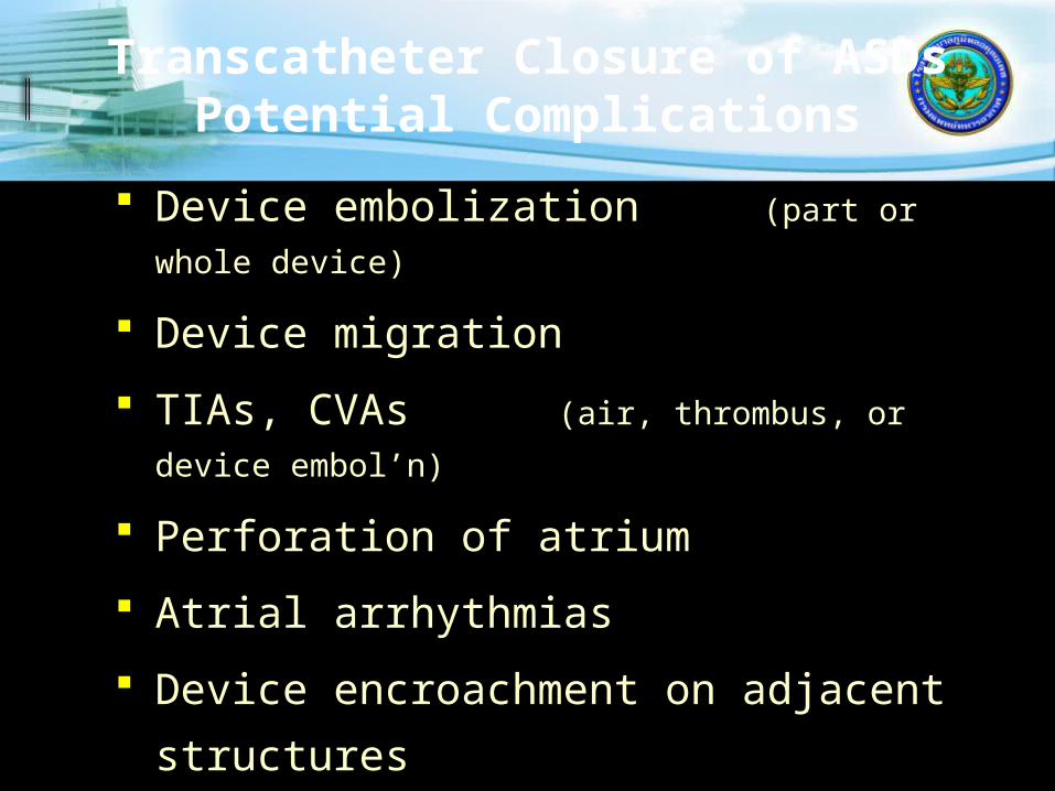
Transcatheter Closure of ASDsPotential Complications
Device embolization (part or whole
device)
Device migration
TIAs, CVAs (air, thrombus, or device
embol’n)
Perforation of atrium
Atrial arrhythmias
Device encroachment on adjacent
structures
Systemic or pulmonary venous
obstruction
Death from procedure

Anatomic EligibilityLeaflet mal-coaptation resulting
in MR
Non-rheumatic/endocarditic valve morphology; LVIDs ≤55mm; MVA ≥4cm2
Feldman T, Kar S, Rinaldi M, Fail P, Hermiller J, Smalling R, Whitlow PL, Gray W, Low R, Herrmann HC, Lim S, Foster E, Glower D Percutaneous Mitral Repair with the MitraClip System: Safety and Midterm Durability in the Initial EVEREST Cohort
J Am Coll Cardiol 54:686-694, 2009
Central MR – Primary Jet in A2-P2

MitraClip: First-in-class Percutaneous Mitral Valve Repair
SystemClinical evidence demonstrates*:- Superior safety when compared to surgery- Reduction in mitral regurgitation- Favorable left ventricular remodeling- Improvement in patient symptoms- Reduction in hospitalizations for heart failure
The MitraClip:- Establishes vertical coaptation while capturing the
leaflets and drawing them together- Repositionable to allow real-time MR assessment prior to
deployment- Safety and effectiveness are supported by data from the
EVEREST clinical trial program and numerous real-world studies
*N ENGL J MED 2011; 364:1395-1406. MitraClip is subject to prior training requirement as per the Instruction for Use.

Mitral Valve Clip
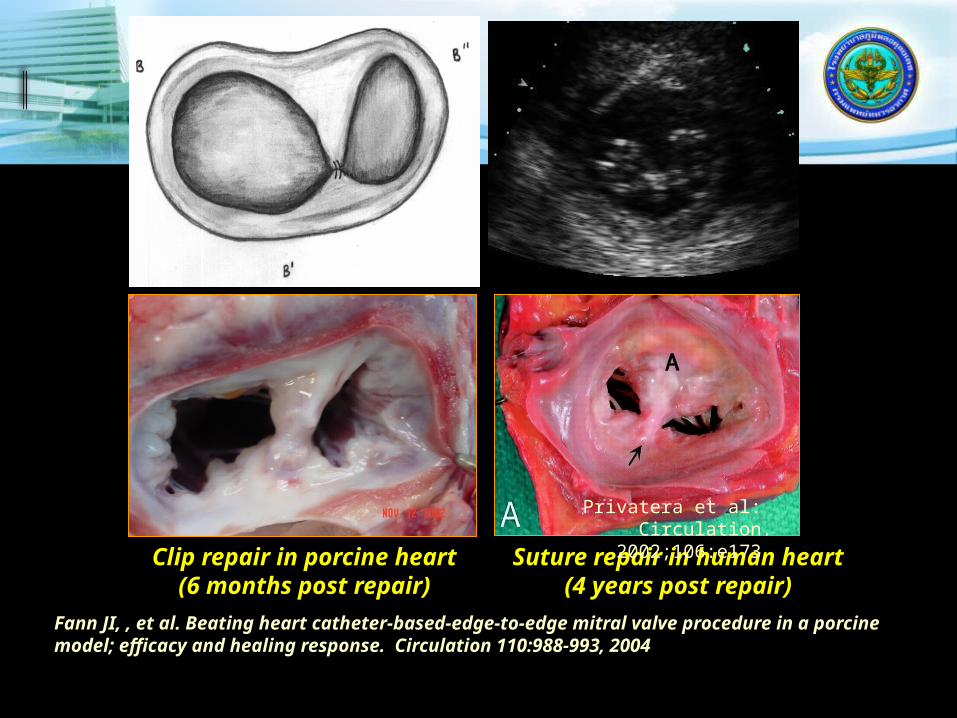
Clip repair in porcine heart(6 months post repair)
Suture repair in human heart(4 years post repair)
Fann JI, , et al. Beating heart catheter-based-edge-to-edge mitral valve procedure in a porcine model; efficacy and healing response. Circulation 110:988-993, 2004
Privatera et al: Circulation. 2002;106:e173
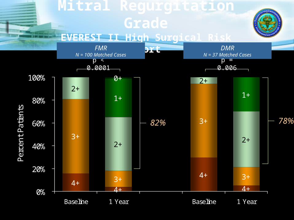
Mitral Regurgitation Grade
EVEREST II High Surgical Risk Cohort
p < 0.0001
FMRN = 100 Matched Cases
4+4+
4+
4+
3+
3+
3+
3+
2+
2+
2+
2+
1+ 1+
0+
0%
20%
40%
60%
80%
100%
Baseline 1 Year Baseline 1 Year
Perc
ent Pa
tient
s
82%
DMRN = 37 Matched Cases
78%
p = 0.006
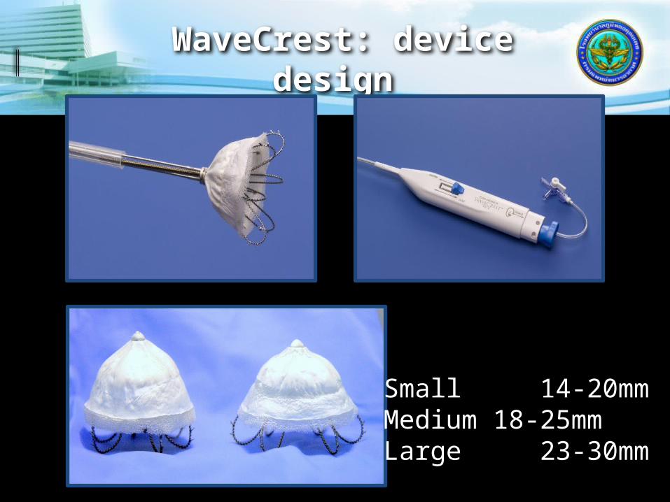
WaveCrest: device design
Small 14-20mmMedium 18-25mmLarge 23-30mm

WaveCrest device design
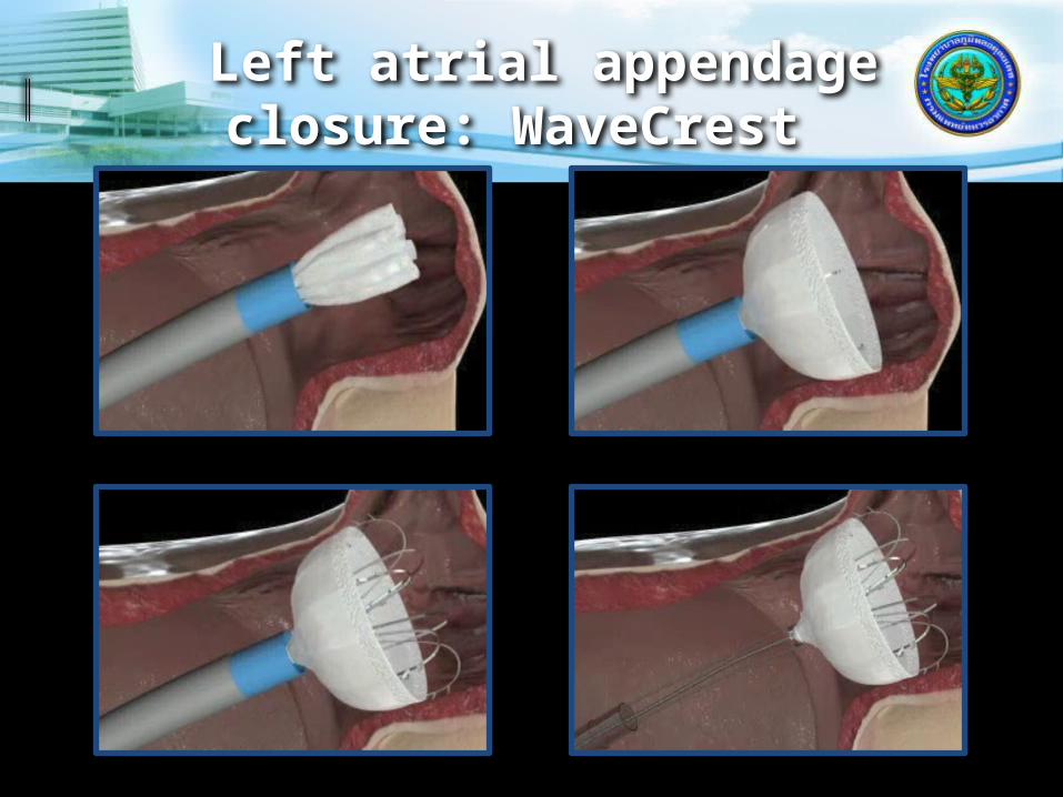
Left atrial appendage closure: WaveCrest


Closure Devices
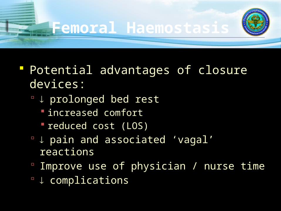
Femoral Haemostasis
Potential advantages of closure devices: prolonged bed rest
increased comfort reduced cost (LOS)
pain and associated ‘vagal’ reactions Improve use of physician / nurse time complications
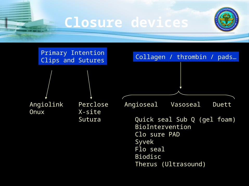
Closure devices
Primary IntentionClips and Sutures
Angioseal DuettVasosealAngiolinkOnux
PercloseX-siteSutura Quick seal Sub Q (gel foam)
BioInterventionClo sure PADSyvekFlo sealBiodiscTherus (Ultrasound)
Collagen / thrombin / pads…
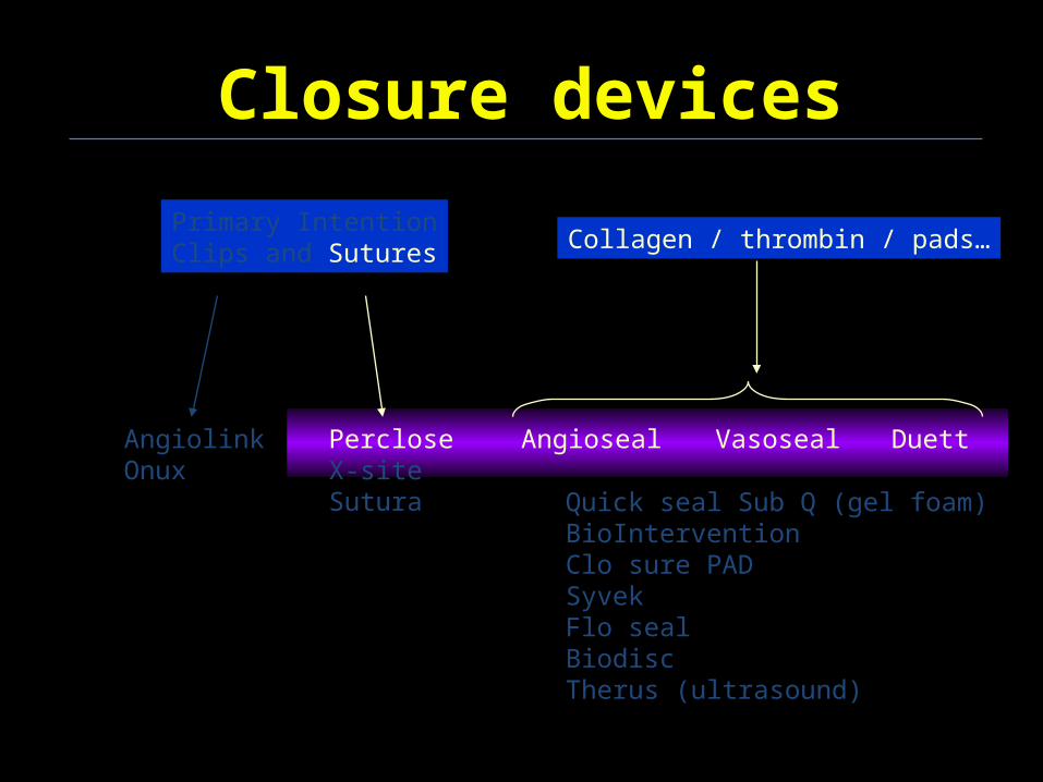
Closure devices
Primary IntentionClips and Sutures Collagen / thrombin / pads…
Angioseal DuettVasosealAngiolinkOnux
PercloseX-siteSutura Quick seal Sub Q (gel foam)
BioInterventionClo sure PADSyvekFlo sealBiodiscTherus (ultrasound)

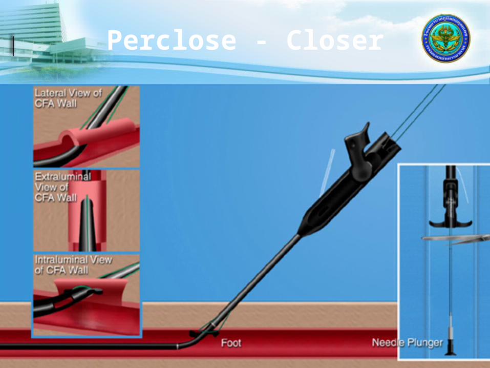
PercloseRedwood City, CA, USA
TechStar 7F - 1 suture
ProStar XL 8F and 10F – 2 sutures
The Closer 6F – 1 suture Knot making tool 3-0 braided polyester (non-absorbable)

Perclose - Closer
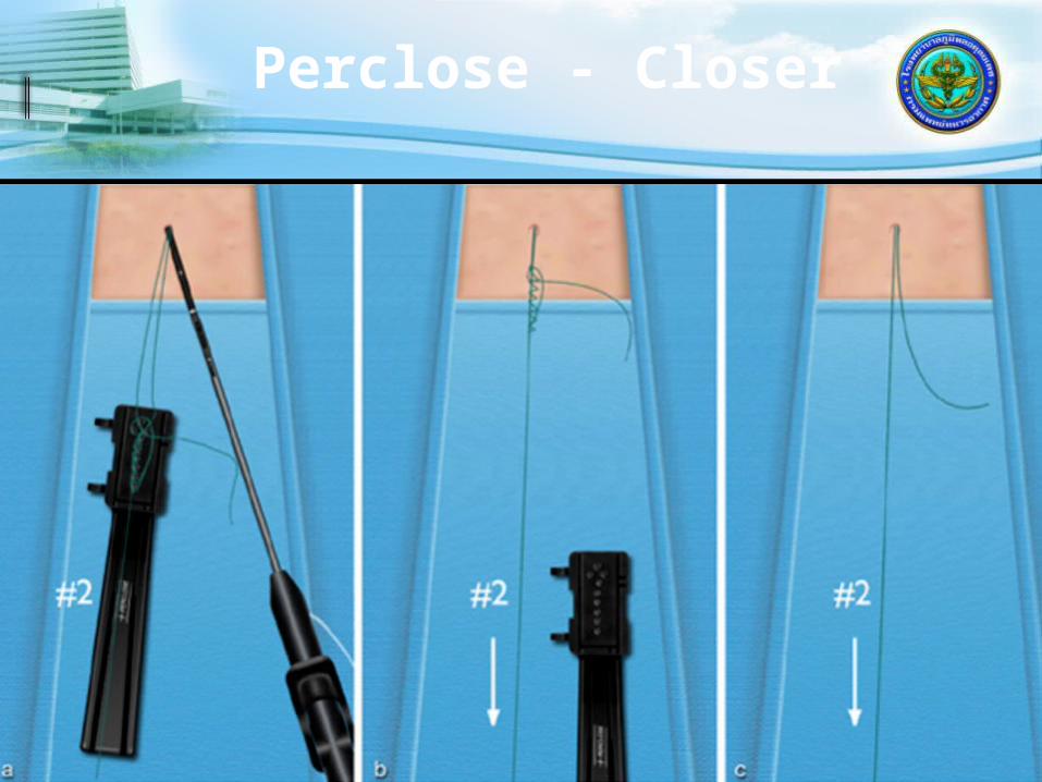
Perclose - Closer

Perclose - Closer
Perclose - Closer
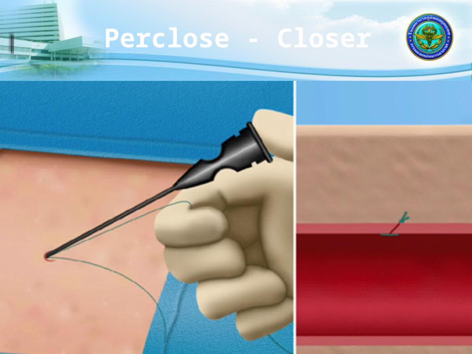
Perclose - Closer
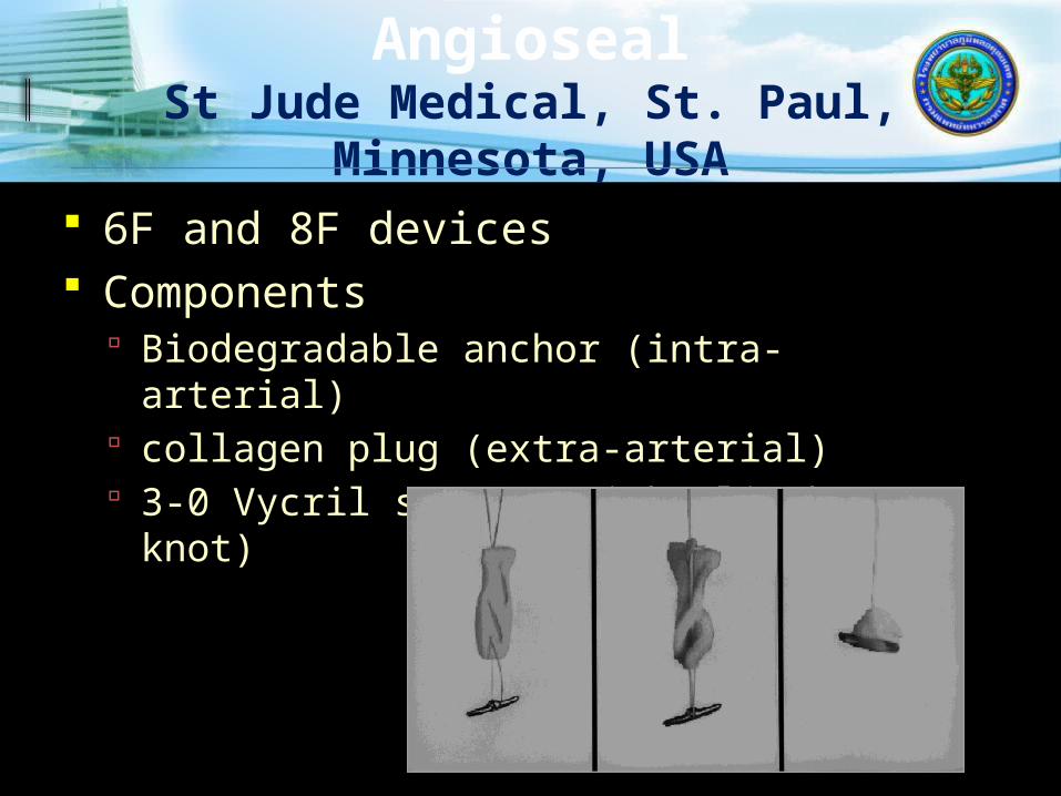
AngiosealSt Jude Medical, St. Paul,
Minnesota, USA 6F and 8F devices Components
Biodegradable anchor (intra-arterial) collagen plug (extra-arterial) 3-0 Vycril suture (with clinch knot)
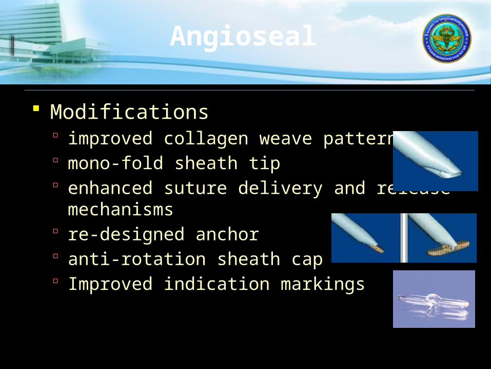
Modifications improved collagen weave pattern mono-fold sheath tip enhanced suture delivery and release
mechanisms re-designed anchor anti-rotation sheath cap Improved indication markings
Angioseal

Angioseal

Angioseal

DuettVascular Solutions Inc.,
Minneapolis, Minnesota, USA
Collagen and thrombin Intra arterial balloon during thrombin
delivery Seals artery and tissue tract Balloon then removed Delivery followed by short period of
manual compression 5F to 9F
Duett
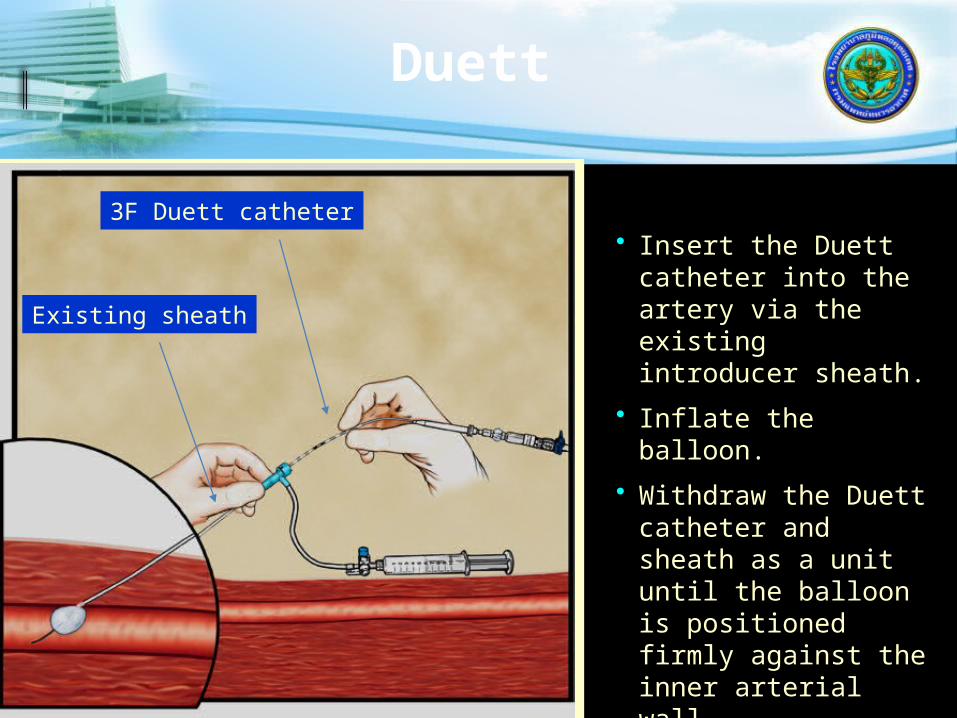
• Insert the Duett catheter into the artery via the existing introducer sheath.
• Inflate the balloon.
• Withdraw the Duett catheter and sheath as a unit until the balloon is positioned firmly against the inner arterial wall.
3F Duett catheter
Existing sheath
Duett
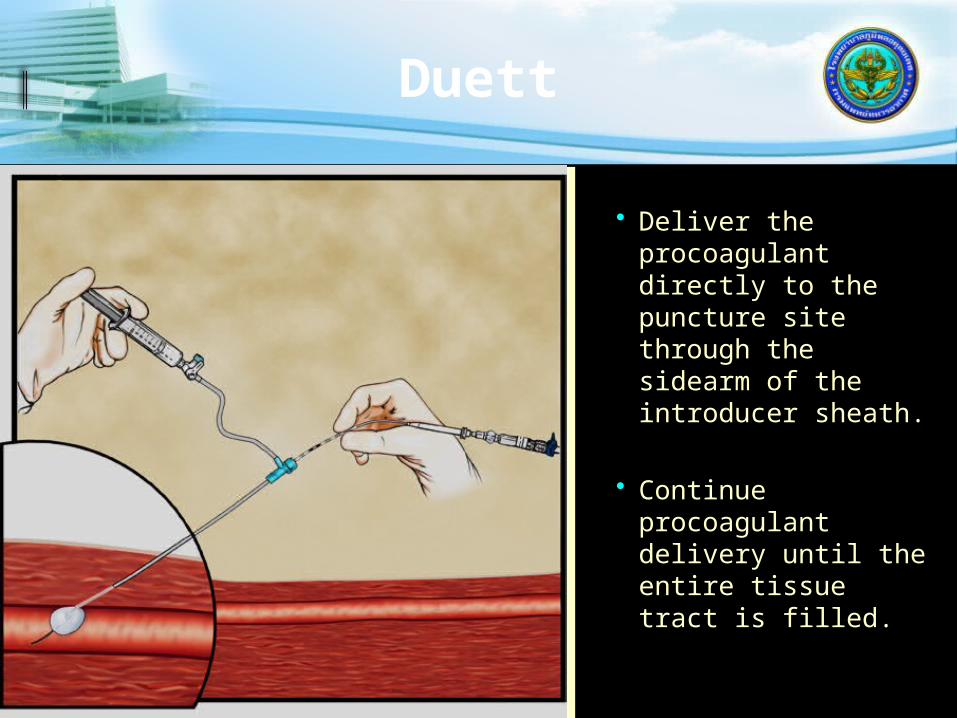
• Deliver the procoagulant directly to the puncture site through the sidearm of the introducer sheath.
• Continue procoagulant delivery until the entire tissue tract is filled.
Duett
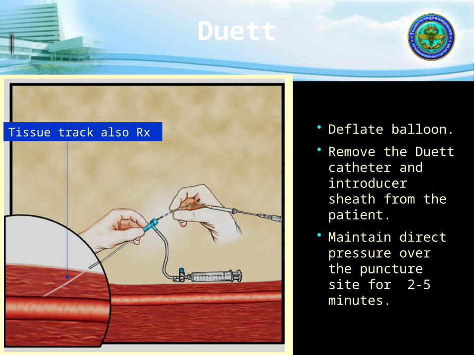
• Deflate balloon.
• Remove the Duett catheter and introducer sheath from the patient.
• Maintain direct pressure over the puncture site for 2-5 minutes.
Tissue track also Rx

Puncture site
External Iliac
Profunda femoris Superficial femoral
retroperitoneal haemorrhage
A-V fistulapseudoaneurysmthrombosisvessel laceration
Optimal
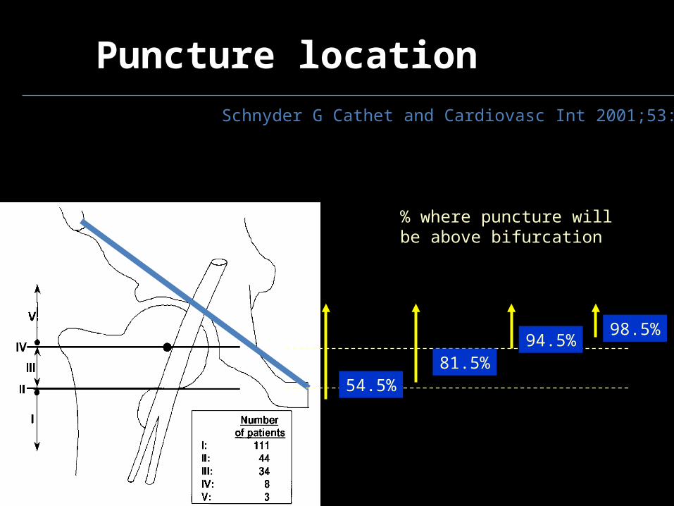
Puncture locationSchnyder G Cathet and Cardiovasc Int 2001;53:289
54.5%
% where puncture will be above bifurcation
81.5%
98.5%94.5%
New complications
Skin tract ooze Failed closure Device Infection Arterial obstruction


