
Introduction to Spitzer and some applications
Data products
Pipelines
Preliminary work
K. Nilsson, J.M. Castro Cerón,J.P.U. Fynbo, D.J. Watson, J. Hjorth and A.L. Aguilar Minor

- launched 25 August 2003; Cape Cañaveral, Florida (USA)
- 2.5 year mission (nominal length; 5+ expected)
- 0.85 m telescope
- 3 cryogenically cooled science instruments (< 5.5 K)
- wavelengths: imaging/photometry 3 – 180 m
spectroscopy 5 – 40 m
spectrophotometry 50 – 100 m
- diffraction limit: 6.5 m

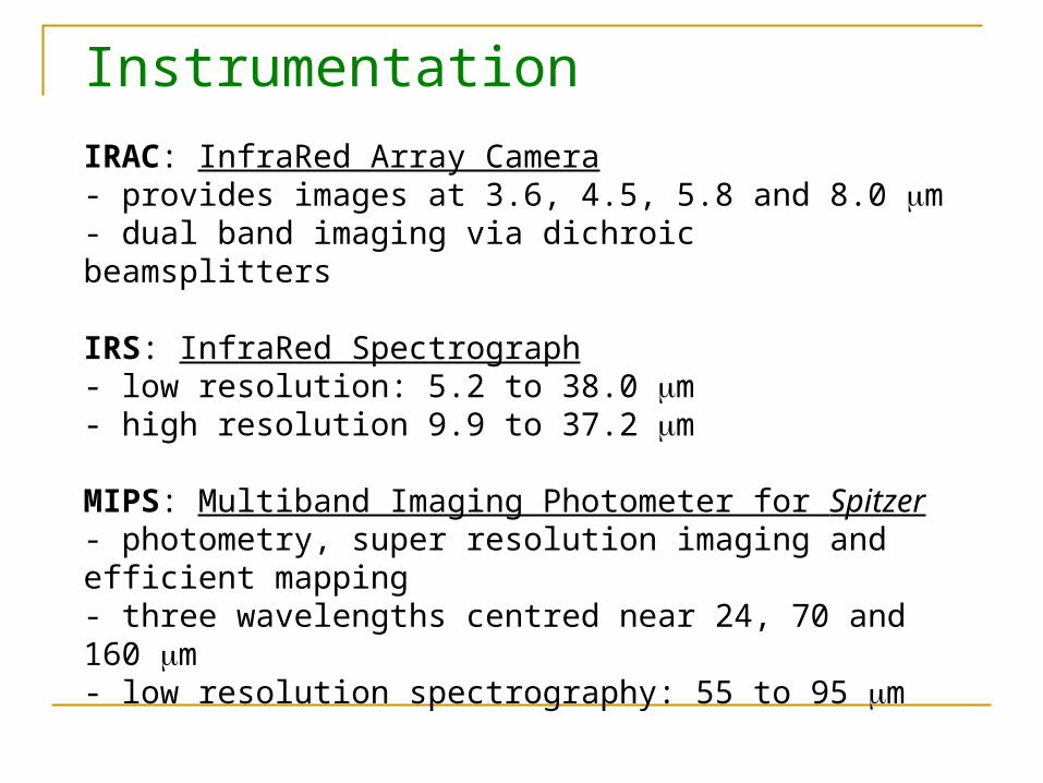
Instrumentation
IRAC: InfraRed Array Camera- provides images at 3.6, 4.5, 5.8 and 8.0 m- dual band imaging via dichroic beamsplitters
IRS: InfraRed Spectrograph- low resolution: 5.2 to 38.0 m- high resolution 9.9 to 37.2 m
MIPS: Multiband Imaging Photometer for Spitzer- photometry, super resolution imaging and efficient mapping- three wavelengths centred near 24, 70 and 160 m- low resolution spectrography: 55 to 95 m

Observation planning
SPOT: a publicly available software package used by Spitzer observers to plan observations and submit proposals.
Data archive
LEOPARD: a publicly available software package used to download data.

Data products
RAW- unprocessed data packaged into a FITS format- calibration data is also provided
BCD (basic calibrated data)- single frame FITS format data products- removal of known instrumental signatures necessary
(dark subtraction, multiplexer bleed, detector linearisation, flat fielding and cosmic ray detection)
- calibrated in scientifically useful units
Post BCD- in each wavelength this processing yields corrected images co-added into a mosaic and a list of extracted point sources

Pipelines
RAW -> BCD- no pipeline is publicly available at this time- SSC pipe linked to many external libraries/modules- will not work outside SSC- user is alone
BCD -> Post BCD- publicly available- made up of several modules (Perl scripts)- Linux and/or Solaris

Post BCD modules (IRAC ch1/2(3/4))
COSMETIC FIX- fixes two artifacts present in IRAC
*multiplexer bleeding: enhanced output level pixels trailing a bright spot*column pull down: intensity reduction of the signal at ~35,000 DN
- optional background subtraction
FLAT FIELD CORRECTION- creates a flat field for one set and applies it to images in the set
BACKGROUND MATCHING/OVERLAP- cumulative pixel by pixel difference between overlapping areas for all pairs is minimised with respect to unknown constant offsets of the input- interpolation is linear -> offset is conserved

POINTING REFINEMENT- improves the pointing provided by the on-board star tracker by minimising discrepancies between positions of point sources matched in each pair of images- relative (self consistent images) or absolute (usually 2MASS)
MOSAICING (with/out outlier detection)- interpolation and co-addition of input images onto a common grid- area overlap interpolation is performed- drizzle interpolation is implemented- correction for optical distortion in the input images is applied during interpolation
ASTRONOMICAL POINT SOURCE EXTRACTION- multi-frame and single-frame point source extraction- for multi-frame, the extraction is performed on co-added image

BANDMERGING- reads two to seven input ASCII table files of single band point source information and produces a list of band combinations

A)-0.8233 ± 0.0072-0.8144 ± 0.0069B) 0.9156 ± 0.0328 0.8956 ± 0.0328C) 1.7675 ± 0.0612 1.6675 ± 0.0621
OURS
SSCD) 1.3682 ± 0.1080 1.2661 ± 0.1055E) 0.7336 ± 0.0428 0.7116 ± 0.0401F) 1.2188 ± 0.0471 1.1800 ± 0.0442

GRB hosts: faint, blue sub-mm galaxies

GRB hosts: faint, blue sub-mm galaxies

Ly-selection of high redshift galaxies

GOODS – Great Observatories Origins Deep Survey Joint effort of NASA, ESO, ESA, NOAO... ”Great observatories”: Spitzer, HST, VLT, CXO,
XMM... Goal is to ”study galaxy formation and evolution over
a wide range of redshifts and cosmic look-back time”.
Two fields with deep observations: HDF-N and CDF-S (and HUDF).

HST vs. Spitzer – the battle of giants


