
1 For support email: [email protected]
Ion Illuminator™ Spectral Analysis System
Release V1 User’s Guide

2 For support email: [email protected]
IonField Systems One Executive Drive Suite 8 Moorestown, NJ 08057 Phone: +1.856.437.0330 Fax: +1.856823.1426 Email:[email protected] www.ionfieldsystems.com Ion Illuminator is a registered trademark of IonField Systems. Copyright ©2014 IonField Systems Rev 1/2014

Preface
3 For support email: [email protected]
Preface Limited Warranty
All Ion Illuminator(s) and accessories sold by IonField Systems are under warranty against manufacturing defects in parts for the twelve (12) month period from the date of installation. For countries with longer warranty requirements, the variation will be noted on the documentation shipped with the instrument. If a customer elects to do a self-‐installation, the warrantee period begins the date the system is shipped to the customer. The Ion Illuminator will operate with the designated automated liquid handler to provide the service for which it is designed in accordance with IonField Systems published specifications.
IonField Systems disclaims all warranties, express or implied, other than those set forth in the published specifications or manufacturer’s instructions for use. IonField Systems expressly disclaims any and all warranties of merchantability and/or fitness for any particular purpose.
Important Cautions and Warnings
The Ion Illuminator is designed for professional, commercial use only and is intended for use in biopharmaceutical, agricultural, forensics, genomics and life science research laboratories. Use of the Ion Illuminator other than for its intended use or in any manner inconsistent with this User’s Guide may cause personal injury, damage to the Ion Illuminator, or affect its operability and constitutes a breach of the applicable Agreement.
The Ion Illuminator is designed to operate only with parts and supplies furnished or approved by IonField Systems. The Ion Illuminator has no user serviceable parts. All service must be provided by persons qualified and authorized by IonField Systems. Unauthorized modifications or repairs to the Ion Illuminator and/or use of parts not supplied by IonField Systems may cause personal injury, damage to the Ion Illuminator, or affect its operability and constitutes a breach of the applicable agreement.
As with other electrical appliances, the Ion Illuminator has specific electrical and environmental requirements. The requirements are set forth in this User’s Guide. Use or operation of the Ion Illuminator with different or fluctuating electric power or in environments not specified may cause personal injury, damage to the Ion Illuminator, or affect its operability and constitutes a breach of the warranty.
For information concerning use of the TipCharger and other IonField products or accessories, please refer to their respective User’s Guides.

Preface
4 For support email: [email protected]
Patent and Trademark Information
The TipCharger is protected by one or more of the following U.S. Patents: 6,724,608, 7,017,594, 7,094,314 and 7,367,344. Three additional patents have issued. Additional patents are pending.
Trademarks are property of IonField unless otherwise noted as property of others.
Copyright Information
This User’s Guide (in print and electronic forms), information contained on any IonField Systems web site, any firmware or software included in the Ion Illuminator and any print or electronic material issued by or for IonField Systems describing the Ion Illuminator or to be used with the Ion Illuminator are the copyrighted property of IonField Systems and may not be copied, republished or decompiled, in whole or part, without the prior written permission of IonField Systems. All rights to such items are reserved by IonField Systems. Requests should be addressed in writing to IonField Systems.
Contact Us
For Sales or Customer Support, please contact IonField's Main Office at +1.856.437.0330
All Cleaning Stations, Controller Modules and Ion Illuminators are labeled with unique serial numbers. Please have the serial numbers for the Cleaning Station, Controller Module and the Ion Illuminator available when contacting Customer Support.
Additional support information, including videos on system operation, is available at www.ionfieldsystems.com
Notice
Cerionx, TipCharger by Cerionx and all other trademarks, copyrights, patents, product designs and related intellectual property formerly the property of Cerionx, Inc. are now property of IonField Systems.

Introduction
5 For support email: [email protected]
Table of Contents
Preface ........................................................................................................... Error! Bookmark not defined.
Limited Warranty ..................................................................................................................................... 3
Important Cautions and Warnings ........................................................................................................... 3
Patent and Trademark Information ......................................................................................................... 4
Copyright Information ............................................................................................................................. 4
Contact Us ............................................................................................................................................... 4
Notice ...................................................................................................................................................... 4
1. Introduction ......................................................................................................................................... 6
Purpose .................................................................................................................................................... 6
Background .............................................................................................................................................. 6
Features ................................................................................................................................................... 6
2. Components ........................................................................................................................................ 7
Miniature Spectrometer .......................................................................................................................... 7
Metal Shielded Fiber Optics Cable 3’ ....................................................................................................... 7
USB Micro-‐B to USB 2.0 Cable ................................................................................................................. 8
IonField Tip Adapters in either an 8, 96, or 384 style .............................................................................. 8
IonField Ion Illuminator Software Installer .............................................................................................. 8
3. How to Guide ....................................................................................................................................... 9
Initial Setup .............................................................................................................................................. 9
Software Setup ........................................................................................................................................ 9
Begin Testing ......................................................................................................................................... 11
Taking Measurements ........................................................................................................................... 12
Warm up Procedure .............................................................................................................................. 13
QC Procedure ......................................................................................................................................... 14
4. Example Program Output .................................................................................................................. 15

Introduction
6 For support email: [email protected]
1. Introduction Purpose
This guide is a quick reference and operating guide on how to operate the Ion Illuminator Emission Spectra product and software.
Background
The Ion Illuminator consists of a small, lightweight spectrophotometer, a fiber optic cable, custom solid printed adapters for 8, 96, or 384-‐channel IonField cleaning stations and custom IonField software to guide use and capture the data output. The Ion Illuminator allows an operator to easily set up and test plasma density in a short amount of time.
Features
The Ion Illuminator software was designed to be simple and easy to use. It has numerous features that can tailor the operation to the user’s needs.
-‐ Column/Row configuration: The operator can choose any configuration of rows and columns to test. In addition, the operator can create new testing configurations, save them, and load them later for future tests. The configuration is also easily editable on the fly during testing.
-‐ Integration time variable: The program allows the operator to change at will the integration time (the time the spectrometer collects light for a measurement). The higher the integration time value, the higher the measurement’s value will be (with a resulting high accuracy) but also this increases the time required to perform a QC test.
-‐ Wavelength selection: The software allows the operator to change the wavelength selected for a measurement. We recommend between 336-‐337 nm for highest accuracy.
-‐ Mistakes: If a data point is invalid or the operator makes a mistake, this value can be re-‐tested immediately.
-‐ Integration with Excel: The Ion Illuminator software outputs a .txt file with tab delimitated values for import into Excel, a quality control software package, or another analysis package.
How to Guide
7 For support email: [email protected]
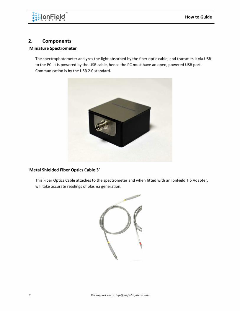
2. Components Miniature Spectrometer
The spectrophotometer analyzes the light absorbed by the fiber optic cable, and transmits it via USB to the PC. It is powered by the USB cable, hence the PC must have an open, powered USB port. Communication is by the USB 2.0 standard.
Metal Shielded Fiber Optics Cable 3’
This Fiber Optics Cable attaches to the spectrometer and when fitted with an IonField Tip Adapter, will take accurate readings of plasma generation.

How to Guide
8 For support email: [email protected]
USB Micro-‐B to USB 2.0 Cable
The USB Micro-‐B to USB 2.0 Cable connects the spectrometer to a Windows PC.
IonField Tip Adapters in 8, 96, or 384 style
The IonField Tip Adapters attach onto the end of the spectrometer and assist in locating the fiber optic tip onto the individual wells to collect data.
IonField Ion Illuminator Software Installer
Example Program Output
9 For support email: [email protected]
3. How to Guide Initial Setup
1. Install the Ion Illuminator software by double clicking on the Setup.exe file. 2. Restart your computer. 3. To confirm the spectrometer is working with your computer, plug the USB cord into a USB
port on your computer. A dialog box at the bottom right corner of your screen indicating ‘device installed properly’ should appear.
4. Secure the fiber optic cable into the spectrometer by gently pushing it in then twisting the outer casing into the connector until it is finger tight. Caution: Fiber Optics cables can snap if they are bent too much. Allow the cable adequate room to curve gently.
Software Setup
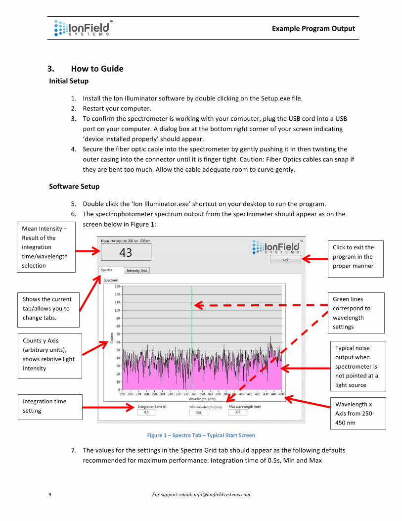
5. Double click the ‘Ion Illuminator.exe’ shortcut on your desktop to run the program. 6. The spectrophotometer spectrum output from the spectrometer should appear as on the
screen below in Figure 1:
Figure 1 – Spectra Tab – Typical Start Screen
7. The values for the settings in the Spectra Grid tab should appear as the following defaults recommended for maximum performance: Integration time of 0.5s, Min and Max
Typical noise output when spectrometer is not pointed at a light source
Wavelength x Axis from 250-‐450 nm
Green lines correspond to wavelength settings
Mean Intensity – Result of the integration time/wavelength selection
Click to exit the program in the proper manner
Shows the current tab/allows you to change tabs.
Counts y Axis (arbitrary units), shows relative light intensity
Integration time setting

Example Program Output
10 For support email: [email protected]
wavelengths of 336 and 337 nm. Wavelengths between 336-‐337 nm collect light from the highest of the 5 nitrogen emission peaks from plasma excitation, as seen in Figure 2 below. An integration time of 0.5s produces the optimal reading when balancing time and output accuracy. If the default values above are changed, the new values will become the defaults in the future.
8. Insert the tip of the fiber optic cable into a well on the TipCharger while it is turned on and operating, and a bright pink graph of the spectrometer output like the one below in Figure 2 should appear. This output shows the peaks for the nitrogen excitation by the plasma, with the green lines at 336/337 nm corresponding to the greatest excitation peak. Try pointing the tip of the fiber optic cable towards different lights sources see how the output changes.
Figure 2 -‐ Spectra Tab -‐ Typical Plasma Spectrum
9. Once you are satisfied with the integration time and wavelength selections, click on the tab labelled ‘Intensity Grid’ to move onto the 2nd tab which should look like the screenshot below in Figure 3:

Example Program Output
11 For support email: [email protected]
Figure 3 -‐ Grid Intensity Tab Default Screen
10. The Intensity Grid tab is the main tab of operating the software and is used to collect measurements.
11. To collect measurements, first select the appropriate TipCharger cleaning station from the drop down menu: TC-‐8 (8 x 1), TC-‐96 (8 x 12) or TC-‐384 (16 x 24).
12. Select the wells that will be measured by clicking anywhere in the Plate Status grid. When a ‘?’ appears after clicking, this well will be available for measurement once the test sequence begins. A preset configuration can be loaded by clicking ‘Load Sequence’ then selecting the appropriate file.
13. Once a sequence has been set, click ‘Save Sequence’ for later runs.
Begin Testing
14. Click ‘Start Sequence’ to begin testing. A box will appear asking for the File Name for the test sequence. Note: the date and time will automatically be appended to the end of the file name once the test is completed.
15. The testing screen will display as shown below in Figure 4:
Select TipCharger Type: TC-‐8 (8 x 1), TC-‐96 (8 x 12), or 384 (16 x 24) Click “Start” button
to begin taking measurements
Match the ‘Glow’ here to the red LED glow in the cleaning station
Load/Save well configurations
Typical well plate numbering/lettering guides
Example Program Output
12 For support email: [email protected]
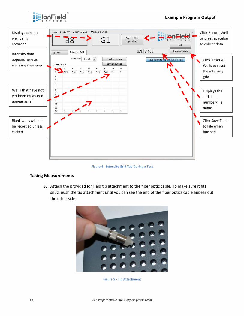
Figure 4 -‐ Intensity Grid Tab During a Test
Taking Measurements
16. Attach the provided IonField tip attachment to the fiber optic cable. To make sure it fits snug, push the tip attachment until you can see the end of the fiber optics cable appear out the other side.
Figure 5 -‐ Tip Attachment
Displays current well being recorded
Intensity data appears here as wells are measured
Wells that have not yet been measured appear as ‘?’
Blank wells will not be recorded unless clicked
Click Record Well or press spacebar to collect data
Click Reset All Wells to reset the intensity grid
Displays the serial number/file name
Click Save Table to File when finished
Example Program Output
13 For support email: [email protected]
17. Inspect the end of the fiber optics cable for any lubricating oil or debris that may have been inside the tip attachment from the manufacturing process. Wipe off any debris with a cotton cloth.
18. Remove Controller POD unit (handheld display with buttons) from the front of the controller. Be careful not to extend the wire too far as this may damage the connection.
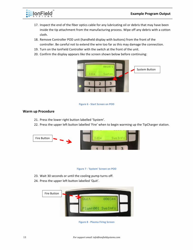
19. Turn on the IonField Controller with the switch at the front of the unit. 20. Confirm the display appears like the screen shown below before continuing:
Figure 6 -‐ Start Screen on POD
Warm up Procedure
21. Press the lower right button labelled ‘System’. 22. Press the upper left button labelled ‘Fire’ when to begin warming up the TipCharger station.
Figure 7 -‐ 'System' Screen on POD
23. Wait 30 seconds or until the cooling pump turns off. 24. Press the upper left button labelled ‘Quit’.
Figure 8 -‐ Plasma Firing Screen
System Button
Fire Button
Fire Button

Example Program Output
14 For support email: [email protected]
25. Repeat steps 21-‐24 3 times. 26. Wait until the station has cooled down and the pump turns off.
QC Procedure
27. The cleaning station is now ready to run a QC cycle using the Ion Illuminator. 28. On the Intensity Grid software screen shown in Figure 4, the measurements will be taken
starting from the top left most row/column with a ‘?’. Locate the red ‘Glow’ word to identify the location of the red LED glow on the cleaning station. Insert the tip attachment into the well on the cleaning station that corresponds to the well to be measured next on the Intensity Grid screen. The attachment is designed to stabilize the tip in the well and reduce movements induced by the operator. Push the attachment into the well firmly but gently until it doesn’t rock back and forth easily.
29. Press the ‘Fire’ button on the POD controller to begin firing the plasma to collect a measurement. Note: If the tip is inserted into the red LED row, this may trigger the plasma firing automatically, and it is not necessary to press the Fire button.
30. After an adequate amount of time (usually 2x that of the integration time) the value on the software screen in the upper left corner should stabilize around a value. The intensity will normally vary +/-‐ 5% due to inherent fluctuations in plasma generation intensity. If necessary, the integration time on the ‘Spectra’ tab can be changed to reduce measurement fluctuations. However, do not change the integration time during a test. All values during a test must be taken using the same integration time or they will vary significantly.
31. When satisfied with the output reading, press the spacebar or click the Measurement button to record the well data.
32. The intensity reading will appear in the Intensity Grid well location where the measurement was collected.
33. Repeat steps 29-‐32 making sure to allow enough time before each reading for the intensity number to stabilize.
34. Note: The plasma may be activated and turned off by pressing the Fire and Quit button for every measurement, or it can be left on to take multiple readings. However, as heat buildup will cause plasma generation to change, leaving the plasma on during measurements will cause the readings to change. This occurs fairly consistently, so this issue may be mitigated by creating a standard procedure for performing a QC test. If the plasma is left on for longer than 53 seconds, it will automatically trigger the safety turn off and may or may not run the cool down air pump. If the cool down air pump runs, it is recommended to wait until the cool down air pump turns off to continue measuring.
35. If any measurements need to be repeated during a run, simply click on the well in the Intensity Grid to change the number back to a ‘?’, or remove it from the well list by clicking again. Any measurements can be repeated before finishing all the wells.
36. When satisfied with the measurements and no more ‘?’ are left on the Intensity Grid, click ‘Save Table to File and Clear Table’. If any ‘?’ are left on the grid, they will be marked as empty in the final output.
Example Program Output
15 For support email: [email protected]
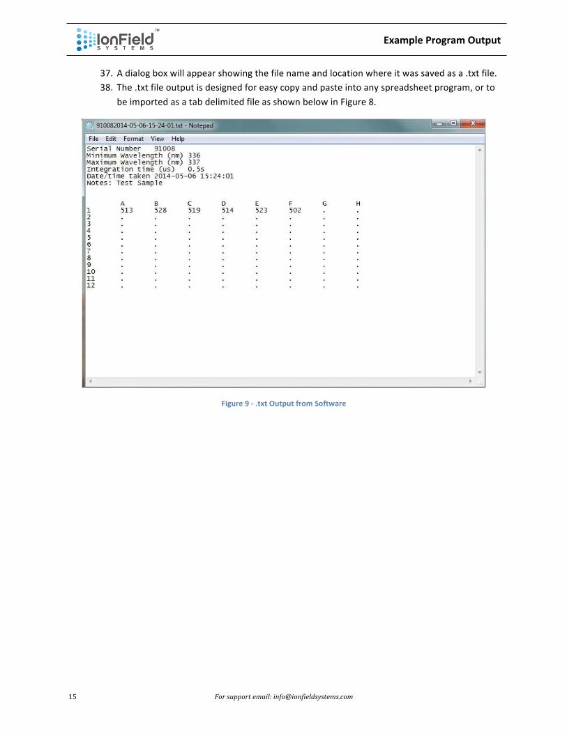
37. A dialog box will appear showing the file name and location where it was saved as a .txt file. 38. The .txt file output is designed for easy copy and paste into any spreadsheet program, or to
be imported as a tab delimited file as shown below in Figure 8.
Figure 9 -‐ .txt Output from Software


