Download - ISE WS 85 engl.02/06 - TEMA Maquinaria

1
ISENMANN
... WS 85 Programms
2
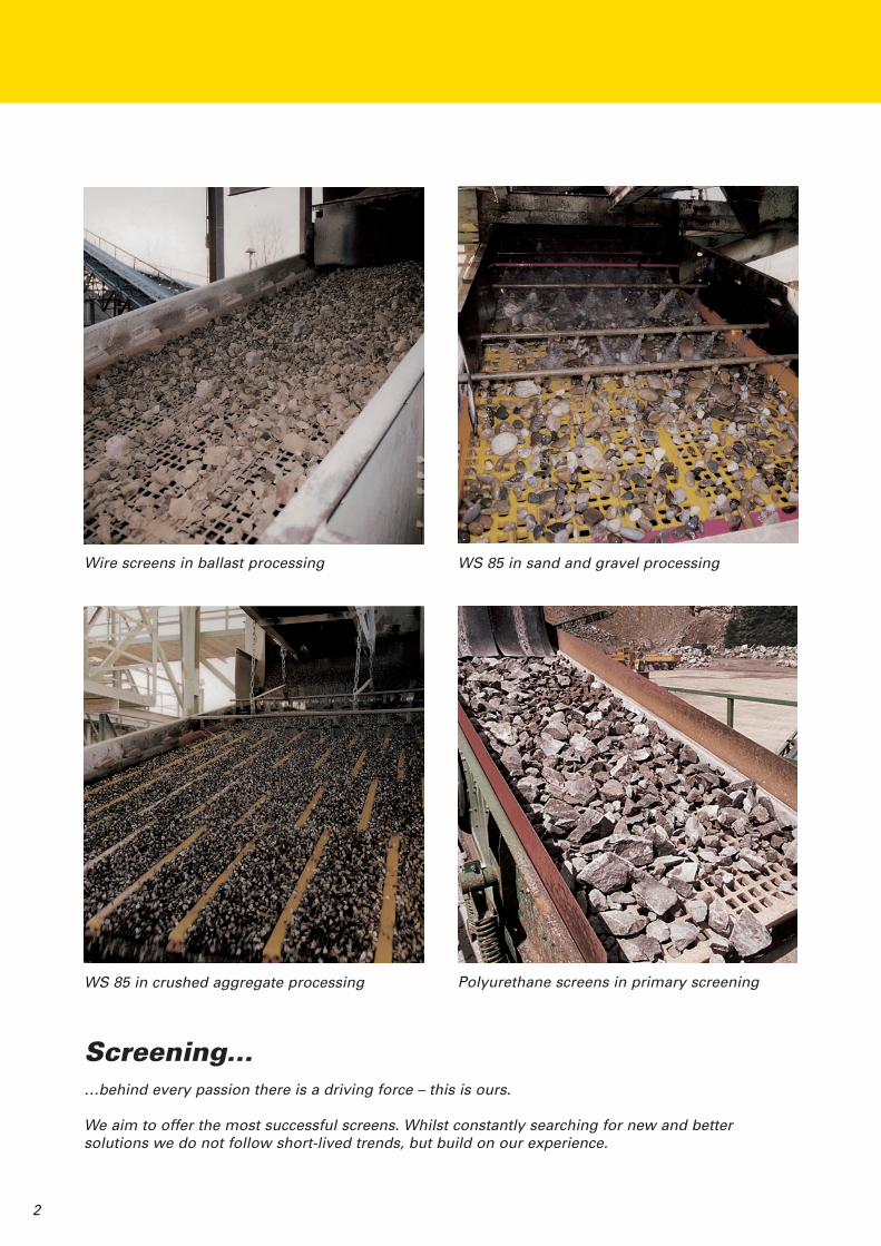
Wire screens in ballast processing
WS 85 in crushed aggregate processing
WS 85 in sand and gravel processing
Polyurethane screens in primary screening
Screening...…behind every passion there is a driving force – this is ours.
We aim to offer the most successful screens. Whilst constantly searching for new and bettersolutions we do not follow short-lived trends, but build on our experience.

3
ISENMANN started manufacturingpolyurethane screens in 1973:
- stretched tensioned versions- flat versions- flat screen panels in frames- system screen panels
e.g.
Interchangeable screen system “WS 43” since 1978
Interchangeable screen system “WS 80” since 1980
Interchangeable screen system “WS 83” since 1983
Interchangeable screen system “WS 85” since 1984A very successful screening systembacked by a great deal of experience.
Further developements are centred aroundthis system with its typical dimensions.
ISENMANNHistory of the screenThe oldest screens known consisted of woodenbars and finer screens of horse hair. The firstexact proof for the use of wire as grids goesback to 1556. It was used to process ore. Thefirst patents for this purpose were registered inFrance in 1821.
Louis Herrmann in Dresden specialised inproducing industrial screens since 1838. Thiscompany was pioneering in the developmentof screening processes – and was destroyedduring the Second World War. HEIN LEHMANNwas able to take over the most importantemployees after the collapse, and consequentlyall the rights and experience.
ISENMANN, founded in 1949, was taken overby HEIN LEHMANN in the mid 50s and thuswas able to share HEIN LEHMANN‘s wealth ofexperience.
The plastic material polyurethane was devel-oped by Bayer. The basic patents go back to1937. The raw material basis of polyurethanematerials is crude oil. The most importantisocyanates for polyurethane are made frombenzene and toluoI.
There are very many of applications with thismaterial. The first polyurethane screens weremanufactured in the mid 60s.

4
The basic components of the WS 85 system
WS support girderNOCKIN barInside module type “J”Outside module type “A”Wedge bar for clampingWedge
The inside modules generally have a width of 300 mm. The system is adapted to any machine widthwith the outside modules. The standard lengths of the screen modules and the NOCKIN bars are1000 mm. Further developements are generally centred around the standard dimensions.
System cross-section
Available WS 85 profile support girders
NOCKIN bars
NOCKIN bars with lateral protection NOCKIN bars
Standard For specialdewateringapplications
For ball trays
For profile 90x50 For profile 80x40
300 300 300
13,813,8
13,8
y
yy
y
x x x x x x
50 40
9085
5 5
520
520
1020
75
80 40
40y
y
300 150
175325
y
y
x x
40
13,8
25
6025
8515
40
x x
y
y
13,8
�
� � �
� ������
�
�
� � �� �
Profile sizes 90x50 80x40 40x40 25x40 25x40 + 60x15Weight (kg/m) 9,411 7,839 4,695 3,516 10,612Wx (cm3) 23,819 16,233 4,963 2,197 18,363Wy (cm3) 19,701 12,863 6,696 4,384 5,228Length max. 8700 8700 6050 6050 6050
� � �� �
5
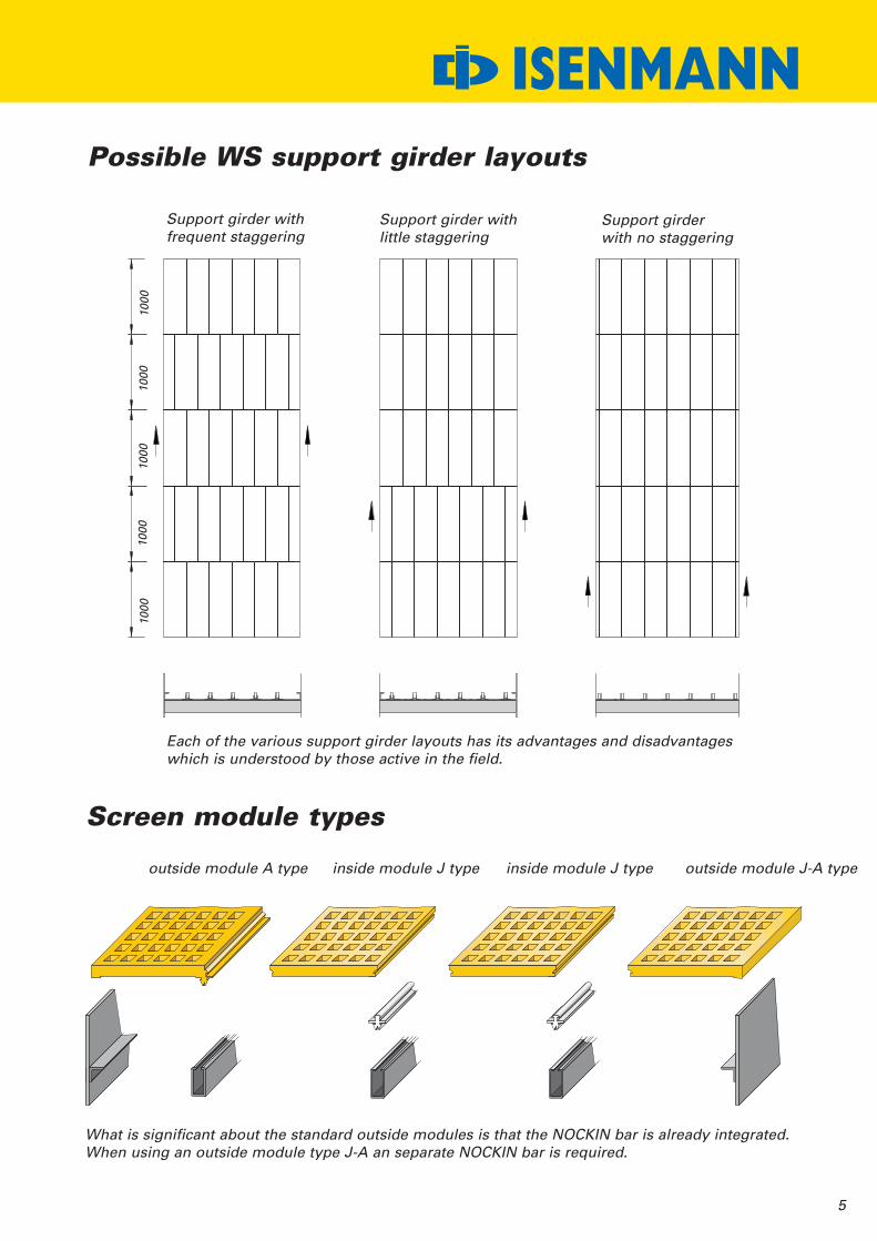
ISENMANNPossible WS support girder layouts
Screen module types
Support girder withfrequent staggering
Support girder withlittle staggering
Support girderwith no staggering
outside module A type
Each of the various support girder layouts has its advantages and disadvantageswhich is understood by those active in the field.
inside module J type inside module J type outside module J-A type
1000
1000
1000
1000
1000
What is significant about the standard outside modules is that the NOCKIN bar is already integrated.When using an outside module type J-A an separate NOCKIN bar is required.
6
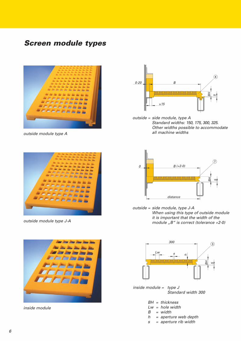
Screen module types
outside = side module, type AStandard widths: 150, 175, 300, 325.Other widths possible to accommodateall machine widthsoutside module type A
outside module type J-A
inside module
outside = side module, type J-AWhen using this type of outside moduleit is important that the width of themodule „B“ is correct (tolerance +2-0)
inside module = type JStandard width 300
BH = thicknessLw = hole widthB = widthh = aperture web depths = aperture rib width
B
≥15
0-20
BH 5
distance
B
BH 5
0
300
BH 5
Lw s h
�
�
�
(+2-0)
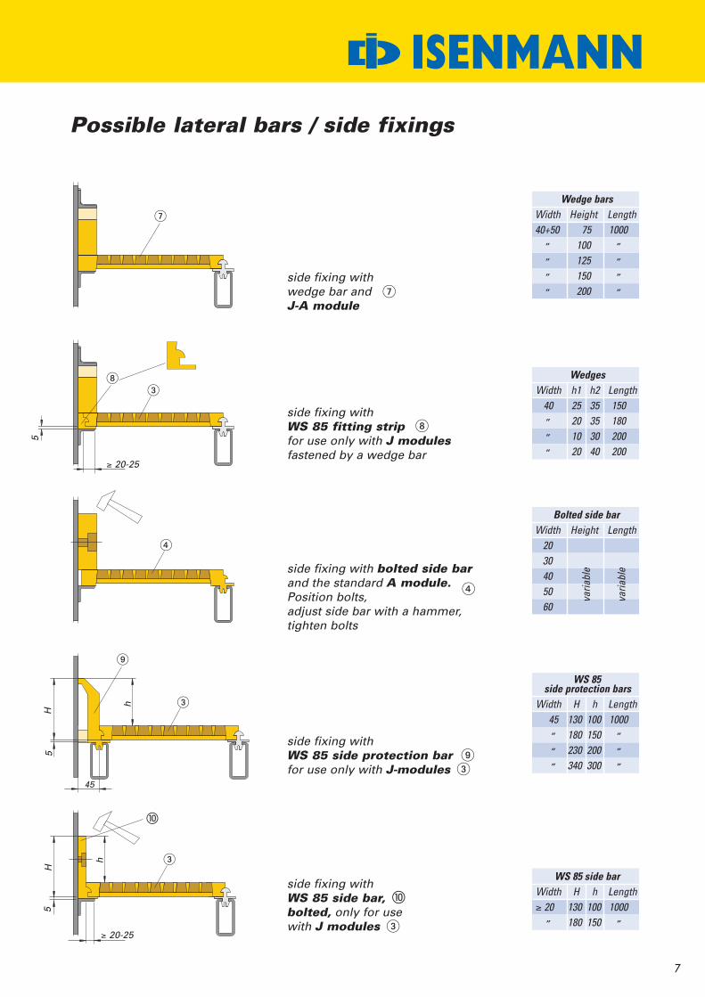
side fixing withWS 85 side protection barfor use only with J-modules �
7
ISENMANNPossible lateral bars / side fixings
side fixing withwedge bar andJ-A module
side fixing withWS 85 fitting stripfor use only with J modulesfastened by a wedge bar
side fixing with bolted side barand the standard A module.Position bolts,adjust side bar with a hammer,tighten bolts
side fixing withWS 85 side bar,bolted, only for usewith J modules
Wedge barsWidth Height Length40+50 75 1000
„ 100 „„ 125 „„ 150 „„ 200 „
WedgesWidth h1 h2 Length
40 25 35 150„ 20 35 180„ 10 30 200„ 20 40 200
WS 85side protection bars
Width H h Length45 130 100 1000„ 180 150 „„ 230 200 „„ 340 300 „
WS 85 side barWidth H h Length≥ 20 130 100 1000
„ 180 150 „
Bolted side barWidth Height Length
2030405060
varia
ble
varia
ble
≥ 20-25
≥ 20-25
45
h
H5
55
h
H
�
�
�
�
�
�
�
�
�
�

8
WS 85 screen module types
VG = Full castScreen modules with one hardnessall the way through
VG-Kb = Full cast combination screenmodules with soft wear layerand hard base
SpG = Full cast, slot aperture forproduct separationScreen modules with one hardnessall the way through or also in„flex“-version
VG-flex = Full cast flexScreen modules with flexibleaperture ribs and hard base
9
ISENMANN
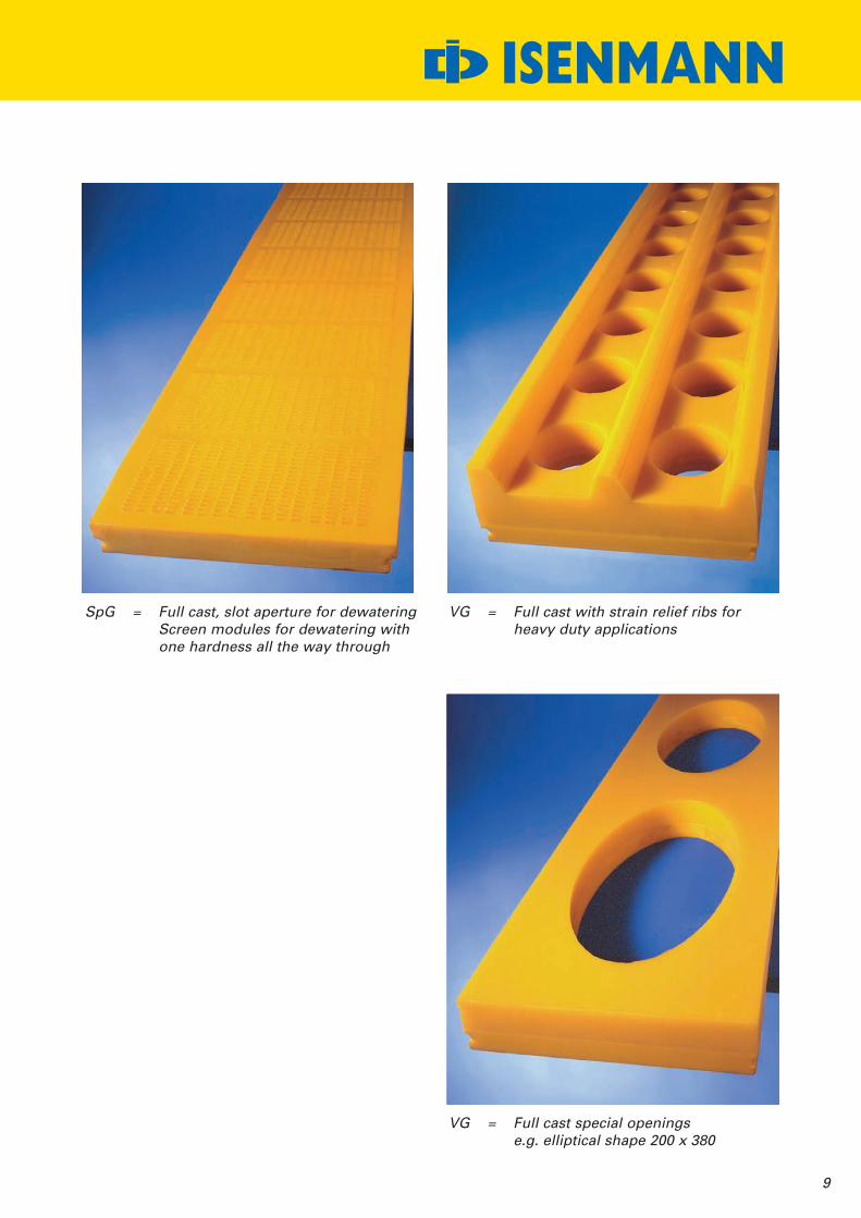
SpG = Full cast, slot aperture for dewateringScreen modules for dewatering withone hardness all the way through
VG = Full cast with strain relief ribs forheavy duty applications
VG = Full cast special openingse.g. elliptical shape 200 x 380
10
WS 85 Screen module types
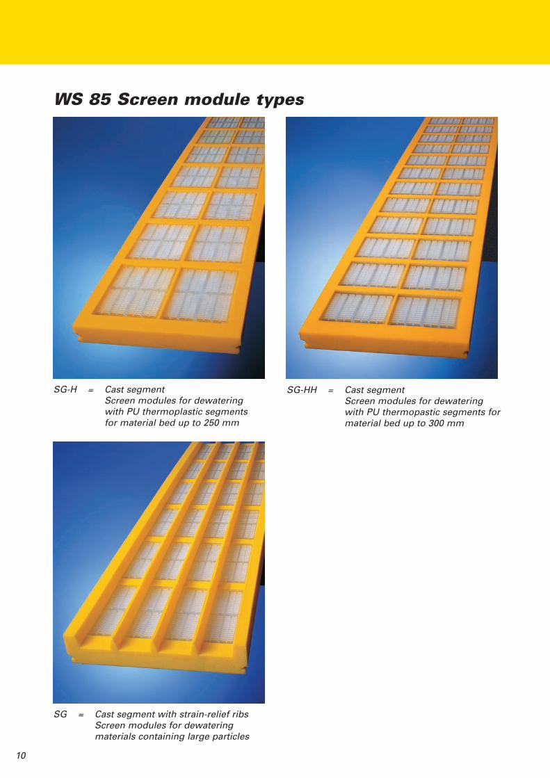
SG-H = Cast segmentScreen modules for dewateringwith PU thermoplastic segmentsfor material bed up to 250 mm
SG-HH = Cast segmentScreen modules for dewateringwith PU thermopastic segments formaterial bed up to 300 mm
SG = Cast segment with strain-relief ribsScreen modules for dewateringmaterials containing large particles

11
ISENMANN
SPM = Tensioned screenScreen module with thin PUmembrane, pretensioned forscreening difficult materials
SPM-flex = Flexible tensioned screen modulesas on the left designed with evengreater flexibility
Gu = Rubber screen Metal screens with WS 85 profiles

12
WS 85 lateral installation... preferred by some clients – here some examples
Side protection with bolted side bar
Side protection with wedged side bar
Bolted side bar
Screen deck
WS support girder Connection withface plates
NOCKIN bar
Nominal length
Nominal length of the NOCKIN bar For a better load transmission, the NOCKIN bar grips10 mm under the side clamping bar
Lengths: Clear width minus 2 x 25 mm = nominal length of the screen fields= nominal length of the NOCKIN bars
Wedge
Wedge bar
Screen deck
WS support girder Bolted connection withbrackets
NOCKIN bar
... a very straightforward and economic option without any wedges or screwsSide protection with lateral moulded side bar
Screen modules
Module joint
Side clamping bar
WS support girder
Clear width of the screening machine
NOCKIN bar180
130
25 25
180
130
10
make upmodulelength
mainmodulelength
modulejoint
FR
Nominal length of the screen modules

150 15025
(250)+Adjustment
300
25
A A
B
BX x 300
Frame joint
X x 300
1400
1270
13
ISENMANN
Example ...
WS 85 screen frame for transverse installation
30025
Drain hole
End bar 30 thick
BH30
NOCKIN barWS 85 inside module 30 thick
Section A-A
Section B-B
35
120
130
Frame joint

14
Separating bars
If WS 85 separating bars are used a differentsupport girder division is required - see sketch.
By using separating bars different screening sizes can be obtained on onescreening deck.
... as WS 85 separating bar
Height up to 300 mm
30
H35
Module widths
Support girder divisionx 315 315 315 315 300
45
... adhered version
x 300 300 300 300 300
x 300 300 300 300 300
45
x 300 300 300 300 300
When using separating bars, bonded on to the edge or slightly offcentre the screen modules, the support girder division remainsat 300 mm.
WS 85 separating bar , height up to 300 mmWS 85 support girderWS 85 type J moduleWS 85 side barWS 85 type A moduleSide barWedgeSeparating bar height to 200 mm
�
�
�
�
� �
� �
� � �
� � �
�
�
� �
�������

15
ISENMANNWS 85 in TANDEM design
... as a relief deckto increase the throughput
... as protective deckto increase the service life of the separation deck
... as a separation deckto obtain four products in one go
J 300 J 300
40
300 300
J 260
45
150
BH 30
BH
Example: Four in one go in a sized aggregate separation with a material feedof 0-8
H2O 0-2 2-5
5-8
16
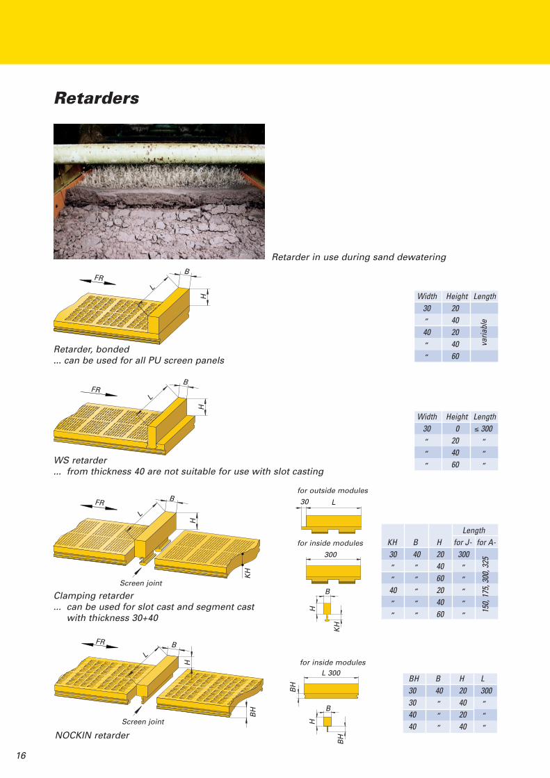
Retarders
Retarder, bonded... can be used for all PU screen panels
WS retarder... from thickness 40 are not suitable for use with slot casting
Clamping retarder... can be used for slot cast and segment cast
with thickness 30+40
NOCKIN retarder
Width Height Length30 20„ 4040 20„ 40„ 60
varia
ble
Width Height Length30 0 ≤ 300„ 20 „„ 40 „„ 60 „
LengthKH B H for J- for A-30 40 20 300„ „ 40 „„ „ 60 „
40 „ 20 „„ „ 40 „„ „ 60 „
BH B H L30 40 20 30030 „ 40 „
40 „ 20 „
40 „ 40 „
H
B
L
H
B
L
H
B
L
Screen joint
KH
for outside modules
for inside modules
30 L
300
KH
H
B
Screen joint
BH
H
BL
for inside modulesL 300
BH
BH
H
FR
FR
FR
FR
150,
175,
300,
325
Retarder in use during sand dewatering
B
17
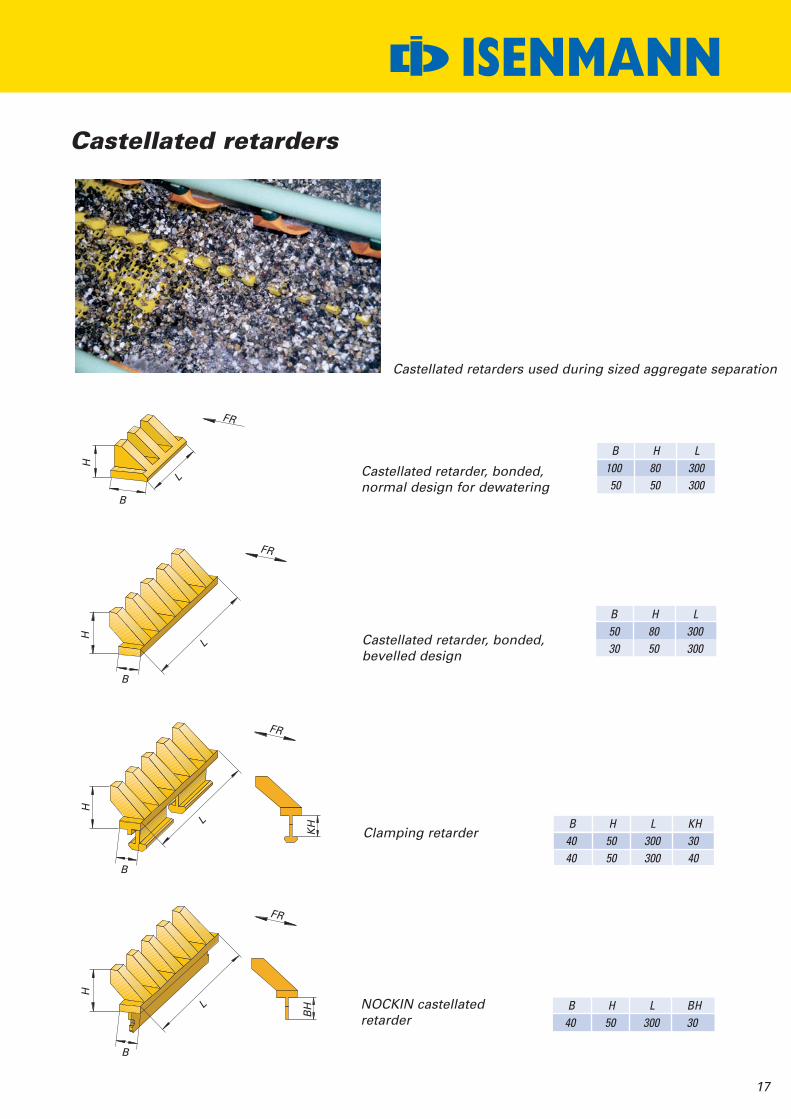
ISENMANNCastellated retarders
Castellated retarder, bonded,normal design for dewatering
Castellated retarder, bonded,bevelled design
Clamping retarder
NOCKIN castellatedretarder
B H L100 80 30050 50 300
B H L50 80 30030 50 300
B H L KH40 50 300 3040 50 300 40
B H L BH40 50 300 30
L
B
H
L
B
H
L
B
H
KH
BHL
B
H
FR
FR
FR
Castellated retarders used during sized aggregate separation
FR

18
Deflectors
NOCKIN deflector with drip apron
type 1.0
type 1.0
type 1.5
type 1.5
type 2.0
type 2.0
Spike deflector, can be screwed in
Deflector, bonding type
BH B H L30 30/60 25/40 30040 „ „ „
B H L30 25 6035 30 70„ 40 „
40 40 80„ 50 „
Screen joint BH
30030 30
30 60
60 60
HH
H
type 1.0
type 1.5 type 2.0
40
60
BH
H
B
L
These deflectors are selected according to deck thickness and type and aresimply assembled in screen module joints.
These deflectors are assembled between the longitudinal screen module joints.Fitting is very easy if a square-headed allen key (20x20) and a battery-poweredscrewdriver are used.
Using a dual component PU adhesive a totally safe bond is attained.
2020
Square-headed allen key
20
20
19
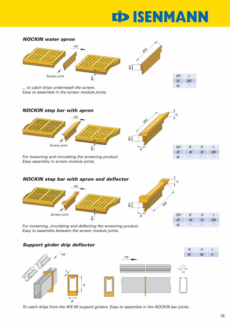
ISENMANNNOCKIN water apron
BH3040
BH B H L30 40 30 30040 “ “ “
BH B H L30 40 25 30040 “ “ “
B H L40 80 6
NOCKIN step bar with apron
NOCKIN step bar with apron and deflector
Support girder drip deflector
Screen joint
BH
BH
Screen joint
BH
BH
Screen joint
FR
L
H
B
300
300
H
BH
B
H
B
BH 30
0
... to catch drips underneath the screen.Easy to assemble in the screen module joints.
For loosening and circulating the screening product.Easy assembly in screen module joints.
For loosening, circulating and deflecting the screening product.Easy to assemble between the screen module joints.
To catch drips from the WS 85 support girders. Easy to assemble in the NOCKIN bar joints.
L300“
FR
FR
FR
FR
20
Knocking facilityWet mineral material has a tendency to cake and blind.A knocking facility can help solve this problem.
Screen deck
Screen panels
� � �
WS support girder
Ball trays
… for longitudinal installation
… for transverse installation
Knocking balls
Ø 50 Ø 55 Ø 60
�
45
BH180
BH130
10 10
10 10
50
WS 85 side barfor ball trays
WS 85 NOCKIN barfor ball trays
Outside barfor ball trays
WS 85 end barfor ball trays
�
�
� � �

21
ISENMANNKnocking facility
Assembly of the ball trays:First the ball trays are assembled in a NOCKIN bar on the WS support girder.Then on the other side of the ball trays a second NOCKIN bar is assembled on the trays which thenis assembled together with the trays on the next WS support girder.
Knocking facility in connection with tension modules used in dry screening of sized aggregates.Separation at 5 mm.
… used during dry screening, mainly up to a separation size of 8 mm.

22
WS 83 wire cloth and wire gridin connection with WS 85
300
Cloth PU Grid
„Y“„X“
300 300 300 300 x-30270
-30270
-30x-30
-30270
Width of thecloth/grid
Using wire cloths in connection with plastic or rubber screens can be advisable,for example:
- when the screen deck is overloaded- when there are short-term changes to a different separation size- when the mineral screening products are wet from the ground
Detail „X“ Detail „Y“15
WS 83 half top bar
Grid/Cloth
WS 85 / WS 83 -Profile lower bar
WS 85 mat
15
WS 83 individual parts
WS 83half top bar WS 83 - top bar
135
185
235
15 10
40
50
WS 83 side bar- 15, for cloth- 10, for grids
WS 83 lower bar- 15, for cloth
WS 83 lower bar- 10, for grids
WS 83 outside bar
15/10
BH 30
WS 83 outside bar

23
ISENMANNWS 83
Assembly sequence per metre:
Tools: Hammer, ~ 2000 gassemply paste or grease/oiland paintbrush
– Lighty lubricate WS support girderand/or WS 83 lower bar
– Assemble the bar into the support girder –ensure that the end of the WS 83 barfits flush with the end of the support girder
– Position the outside bar with theoutside cloth
– Position the center cloth– Assemble all top bars until
they clamp easily– Adjust the cloth again if necessary– Assemble the wedge bars until
they clamp easily– Drive the top bars down into the bottom
section using a hammer– Fix wedge bars
Suitable for wet and dry screeningFor wire cloth and grid
24
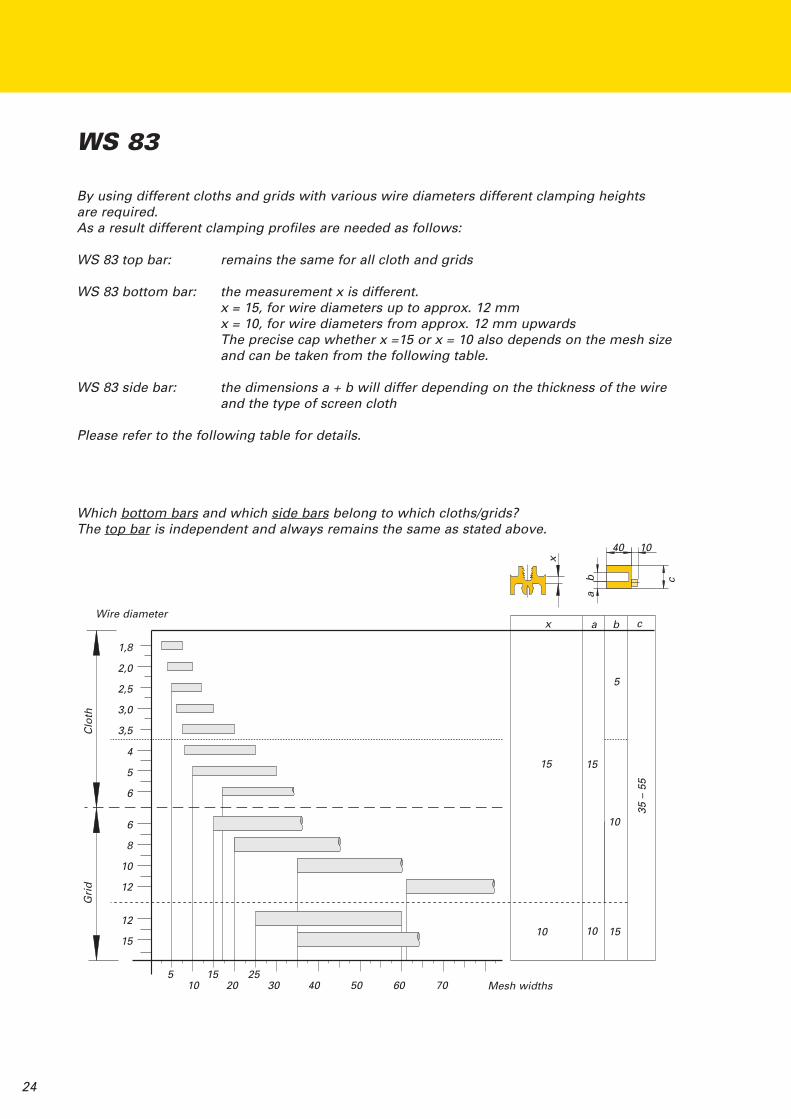
By using different cloths and grids with various wire diameters different clamping heightsare required.As a result different clamping profiles are needed as follows:
WS 83 top bar: remains the same for all cloth and grids
WS 83 bottom bar: the measurement x is different.x = 15, for wire diameters up to approx. 12 mmx = 10, for wire diameters from approx. 12 mm upwardsThe precise cap whether x =15 or x = 10 also depends on the mesh sizeand can be taken from the following table.
WS 83 side bar: the dimensions a + b will differ depending on the thickness of the wireand the type of screen cloth
Please refer to the following table for details.
WS 83
Which bottom bars and which side bars belong to which cloths/grids?The top bar is independent and always remains the same as stated above.
Wire diameter
Grid
Cloth
1,8
2,0
2,5
3,0
3,5
4
5
6
6
8
10
12
12
15
5 15 2510 20 30 40 50 60 70 Mesh widths
10 10 15
15 15
10
5
x a b c
x
ba
40 10
c
35–55

25
When using cloth with wire thicknesses of up to 2.2 mm we recommend overlapping the cloth byabout 15 mm to avoid gaps where the screen modules meet (join (2) + (3)).The adjoining profile bars have an overlap on the discharge side and a notch on the feed side tosupport the cloth ends at the join.
For cloth with wire thicknesses of 2.5 mm to 3.0 mm we recommend using WS 83 top and bottombars with overlaps so that the opposite cloths are supported at the join in order to avoid any gaps(join (4)).
For cloth and grids with wire thicknesses greater than 3.0 mm no overlapping and notches arerequired. The cloths, grids start and end with the respective profile bars.
Screen start the cloths/grids and profile bars start at the same height
Screen join shows a cloth overlapping with wire thicknesses of up to 2.2 mmProfile bar end with 15 mm overlapProfile bar start with 15 mm notch
Screen join shows a cloth overlap to a stronger cloth(e.g. wire diameter 3.0 mm)Profile bar end with 15 mm overlapProfile bar start with 15 mm notch
Screen join shows a cloth join (e.g. wire diameter 3.0 mm)Profile bar end with 15 mm overlapProfile bar start with 15 mm notch
Screen end the cloths/grids and profile bars end at the same height
WS 83 – for support girder layout with offset
ISENMANN
1000 1000 1000 1000
� �� � �
FR
�
�
�
�
�

26
WS 83 profile bars with overlapand/or notch
Please note: The overlap is outside the nominal length of theprofile bar and the notch within the nominal lengthof the profile bar.
Overlap Notch Overlap
Top bar
Bottom bar
WS support girder
15
15Nominal length
(1000)15Nominal length
(1000)
Wire Ø Length of the cloths Length of the profile bars1,8 Nominal length + Overlap Nominal length + Notch + Overlap2,0 Nominal length + Overlap Nominal length + Notch + Overlap2,2 Nominal length + Overlap Nominal length + Notch + Overlap2,5 Nominal length Nominal length + Notch + Overlap3,0 Nominal length Nominal length + Notch + Overlap3,5 Nominal length Nominal length + Notch + Overlap4,0 Nominal length Nominal length5,0 Nominal length Nominal length6,0 Nominal length Nominal length6,0 Nominal length Nominal length8,0 Nominal length Nominal length10 Nominal length Nominal length12 Nominal length Nominal length15 Nominal length Nominal length
Grid
Cloth

27
Dismantling:Tools: Screwdriver, ~ 14 mm
Hammer, ~ 2000 g
– At the end of the bar reach with thescrewdriver under the top bar andlever out upwards. The top bar canthen be removed manually. Loosen thewedge bar and remove the cloth.
Removing the lower bar:– At the end of the bar reach with the
screw driver between the top edgeof the WS support girder and thebottom bar and lever out. The bottombar can be removed manually.
WS 83 with support girder layout without offset
ISENMANN
For cloths with a wire thickness of up to 2.2 mm, we recommend a cloth overlap ofapprox. 15 mm in order to avoid gaps where the cloths join.WS 83 top bar and bottom bars do not have any notch and/or overlap.
1000 1000 1000 1000
PU screenCloth, wire up to2.2 mm Ø
Cloth, wire up from2.5 mm Ø upwards
Cloth, wire up from2.5 mm Ø upwards

28
De-flaking screen... to improve the quality of the granular fractions
During de-flake screening the slot can run with oracross the material flow.
1000
300
Granular product
Flakes
Granular product
Flakes
De-flake screenNOCKIN bar for traysNOCKIN trayNormal separation screens
The flaky material is collected directly under the de-flake screen in the NOCKIN tray,transported and then discharged separate from the good product for furtherprocessing.
��
�
����
�
�
�
��
�
�
�
�
29
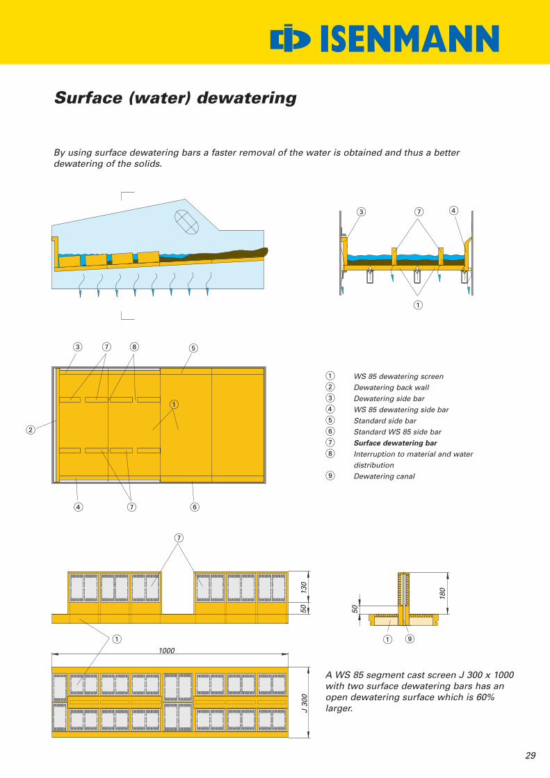
ISENMANNSurface (water) dewatering
By using surface dewatering bars a faster removal of the water is obtained and thus a betterdewatering of the solids.
WS 85 dewatering screenDewatering back wallDewatering side barWS 85 dewatering side barStandard side barStandard WS 85 side barSurface dewatering barInterruption to material and waterdistributionDewatering canal
A WS 85 segment cast screen J 300 x 1000with two surface dewatering bars has anopen dewatering surface which is 60%larger.
1000
50130
50
180
J300
�
�
�
� �
�
�
� �
�
�
� �
�������
�
�
30
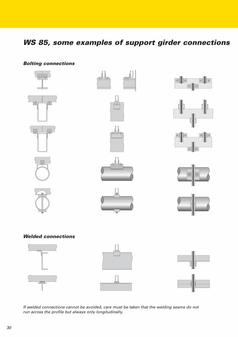
WS 85, some examples of support girder connections
If welded connections cannot be avoided, care must be taken that the welding seams do notrun across the profile but always only longitudinally.
Bolting connections
Welded connections
31
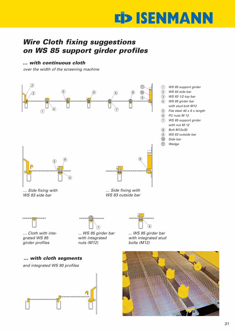
Wire Cloth fixing suggestionson WS 85 support girder profiles
WS 85 support girderWS 83 side barWS 83 1/2 top barWS 85 girder barwith stud bolt M12Flat steel 40 x 8 x lengthPU nuts M 12WS 85 support girderwith nut M 12Bolt M12x30WS 83 outside barSide barWedge
over the width of the screening machine
… Side fixing withWS 83 side bar
… Side fixing withWS 83 outside bar
... WS 85 girder barwith integratednuts (M12)
... WS 85 girder barwith integrated studbolts (M12)
… Cloth with inte-grated WS 85girder profiles
and integrated WS 80 profiles
����
���
��
�
�
�
� �
�
�
�
�
�
��
� �
�
ISENMANN
… with continuous cloth
… with cloth segments

ISENMANN
Elliptical holes
WS 85 … easy to exchange,special holes also available
Circular holes Pear drop holes
msa
/chs
u/m
ed02
/201
0
ISENMANNSiebe GmbH
ISENMANNDrahtsiebe GmbH
TEMAISENMANN Ltd
ISENMANNS.a.r.l.
Postfach 342976020 KarlsruheGerwigstraße 6776131 KarlsruheTel.: +49 (0)721 62 90-0Fax: +49 (0)721 62 90-69+70www.isenmannsiebe.de
Sachsen
Cisinskistraße 901920 Panschwitz-KuckauTelefon +49(0)3 57 96/9 48 80Telefax +49(0)3 57 96/ 9 62 16
Industrial Screening Systems4 Great Central WayWoodford HalseNorthants, NN11 3PZTelefon +44(0)13 27 2642 27Telefax +44(0)13 27 26 42 28www.tema.co.uk
Quartier d´entreprises “Le Fortin“
13 rue Desaix – B.P.9108367452 Mundolsheim CedexTelefon +33 (0) 3 88 83 65 57Telefax +33 (0) 3 88 33 29 48www.isenmann.fr


