
http://wrap.warwick.ac.uk
Original citation: Qureshi, Jawed and Mottram, J. Toby (James Toby), 1958-. (2013) Behaviour of pultruded beam-to-column joints using steel web cleats. Thin-Walled Structures, Volume 73 . pp. 48-56. ISSN 0263-8231
Permanent WRAP url: http://wrap.warwick.ac.uk/56528 Copyright and reuse: The Warwick Research Archive Portal (WRAP) makes this work by researchers of the University of Warwick available open access under the following conditions. Copyright © and all moral rights to the version of the paper presented here belong to the individual author(s) and/or other copyright owners. To the extent reasonable and practicable the material made available in WRAP has been checked for eligibility before being made available. Copies of full items can be used for personal research or study, educational, or not-for-profit purposes without prior permission or charge. Provided that the authors, title and full bibliographic details are credited, a hyperlink and/or URL is given for the original metadata page and the content is not changed in any way. Publisher’s statement: “NOTICE: this is the author’s version of a work that was accepted for publication in Thin-Walled Structures. Changes resulting from the publishing process, such as peer review, editing, corrections, structural formatting, and other quality control mechanisms may not be reflected in this document. Changes may have been made to this work since it was submitted for publication. A definitive version was subsequently published in Thin-Walled Structures, Volume 73, 2013] http://doi.org/10.1016/j.tws.2013.06.019 ¨
A note on versions: The version presented here may differ from the published version or, version of record, if you wish to cite this item you are advised to consult the publisher’s version. Please see the ‘permanent WRAP url’ above for details on accessing the published version and note that access may require a subscription. For more information, please contact the WRAP Team at: [email protected]
J. Qureshi, and J. T. Mottram, ‘Moment-rotation response of beam-to-column joints for pultruded
frames with steel web cleats,’ Thin-Walled Structures, 73, (2013), 48–56. ISSN: 0263-8231
doi.org/10.1016/j.tws.2013.06.019
Behaviour of pultruded beam-to-column joints using steel web cleats
Jawed Qureshi a * and J Toby Mottram
b
a School of Architecture, Computing and Engineering (ACE),University of East London
4-6 University Way, Beckton, London E16 2RD, UK.
b Civil Research Group, School of Engineering, University of Warwick, Coventry, CV4 7AL, UK.
* Corresponding author
ABSTRACT
Response of pultruded Fibre Reinforced Polymer (FRP) beam-to-column joints with steel bolted web
cleats is studied through physical testing. Two joint configurations are considered with either three or
two bolts per cleat leg, as per drawings in a pultruder’s Design Manual. Moment-rotation curves,
failure modes and potential performance gains from semi-rigid action are determined from two
batches, each having six nominally identical joints. Results show that initial joint properties for
stiffness and moment can possess, at 19 to 62%, an extremely high coefficient of variation. All joints
failed by fracturing within the FRP column’s flange outstands. Because this failure mode has not
been reported previously there is a need to establish how its existence influences joint design. As
joint properties for the three- and two-bolted configurations are not significantly different, the middle
(third) bolt is found to be redundant. Damage is shown to initiate within the column flange outstands
when the mid-span deflection of a 5.08 m span beam, subjected to a uniformly distributed load, is
span/500. This is half the serviceability vertical deflection limit recommended in the EUROCOMP
Design Code and Handbook. The mean joint moment resistance for design is established to be 2.9
kNm and this is 1.5 times the moment for damage onset.
Keywords: Bolted connections; steel web cleats; pultruded joints; damage onset; moment-rotation
response.
2
1. Introduction
Pultruded shapes of Fibre Reinforced Polymer (FRP) are used as members in pedestrian footbridges,
buildings, towers, cooling towers, and walkways and platforms. Members of PFRP material are
preferred [1, 2-4] because they offer significant corrosion and chemical resistance. This makes them
attractive for projects where other construction materials would not satisfy the durability
requirements. PFRP shapes are, moreover, chosen when electromagnetic transparency is a design
requirement, as in electronics manufacturing plants [1]. They are also suitable for framed structures
where either accessibility to site is limited and/or lightweight is desirable for fast deployment, such as
footbridges near railway platforms.
Standard pultruded (thin-walled) FRP profiles have the same cross-sectional shape as conventional
steelwork [1]. They consist of E-glass fibre reinforcement (layers of unidirectional rovings and
continuous mats) in a thermoset resin based matrix. The composite material has a density about 0.25
of steel. Technical information on the pultrusion process, and PFRP shapes themselves, is given in
three manufacturers’ Design Manuals [2-4]. Although FRP shapes are similar to steel sections, their
structural behaviour is different. Direct strengths (in the direction of pultrusion) can be over 200
N/mm2, and this is comparable with structural grade steel. The longitudinal modulus of elasticity, at
20 to 30 kN/mm2, is up to 10 times lower, whereas the modulus of elasticity perpendicular to the
direction of pultrusion is about 0.3 of the longitudinal value [2-4]. The in-plane shear modulus has a
value that is about 0.5 of the transverse modulus.
In this paper we will be concerned with construction for simple braced (non-sway) frames that have
simple shear (web-cleated) connections between beams and columns, and columns and bases. To
have non-sway frames diagonal bracing members are required to transfer lateral loads to the ground.
Often the beams and columns are of wide flange pultruded shapes that have equal depth and flange
width. As shown in Figs. 1 to 4 the method of connection with this shape is by steel bolting and joint
detailing can correspond to the engineering drawings in pultruders’ Design Manuals [2-4].

3
Presently, knowledge and understating on the response and failure of such frame joints is limited and
there is lack of design guidelines too [1-5]. Because FRP material has relatively low through-
thickness properties there are concerns within practice about using pultruded leg-angles for web cleat
components that are assumed to offer nominally pinned joints for simple construction [5]. Previous
research by Mottram [6], Mosallam [7] and Mottram and Zheng [8] provides limited joint properties
from full-sized laboratory tests. These series were without specimen repetition and so there is
insufficient evidence to support the proposition that pultruded cleats could be fit for purpose, because
they could experience material (delamination) damage when beams are subjected to service loading.
Mottram and Zheng [9] recognised the relevance of steel cleats as connecting elements in PFRP
joints. In their joint tests, that used the same test arrangement as shown in Fig. 1, the beam and
column shapes were of size 203×203×9.53 mm, and from the Strongwell’s standard range [3]. For
joint details that were to offer semi-rigid action they chose flange cleated connections using steel
angle components of 100×100×8 mm. Both major- and minor-axis tests were conducted with top and
bottom steel seat cleats. There was no specimen repetition and the methods of connection were by
bolting, without and with adhesive bonding. Mottram and Zheng also employed 20 mm dia. steel
rods to connect opposite flange outstands of the column, with top steel seat cleats on both sides to
eliminate the flexibility of the pultruded flange outstands. These internal beam-to-column joints are
not known to have been adopted in practice. The only other measured properties for joints that
connected pultruded members with bolted steel cleats are from Turvey [5]. With a 102×102×6.4 mm
pultruded shape and stainless steel cleats of size 100×100×6 mm, Turvey characterised three joint
configurations for web, flange and web, and flange only cleat details. A weakness with this work is
that the end of the pultruded cantilever beam was connected to a relatively very stiff steel support
angle, thereby nullifying the influence of column flange flexibility by having pultruded column
flanges in the specimen configuration. By choosing a steel support, Turvey unwittingly inhibited the

4
mode of failure that could have occurred had the pultruded column been included in the test
arrangement.
Steel or stainless steel connecting elements are adopted by fabricators because there is uncertainty on
the reliability of having these key components of FRP material. In particular, leg-angle cleats cut
from pultruded shapes are not likely to have acceptable fibre reinforcement to resist the joint
deformations generated from prying action. Three pultruders do not provide guidelines in their
Design Manuals [2-4] as to what design changes would be necessary when web cleats of steel replace
those of FRP. Almost, no physical testing has been conducted when steel leg-angles are used for web
cleats that form the joint detailing shown in Figs. 1 to 3. To know how safe and reliable joints with
bolted steel cleats are, it is vital to characterise their moment-rotation response, modes of failure and
determine the joint properties for stiffness and moment resistance.
This omission led the authors to perform a series of tests with batches of nominally identical steel
web cleated joints for quantifying key joint properties. Qureshi and Mottram [10] have conducted a
very similar test series with web cleats of 192 mm long, 100 mm wide and 9.53 mm thick pultruded
leg-angle. The principal feature of the new contribution to understanding is that of specimen
repetition. This advancement is crucial to be able to statistically quantify the joint properties, and,
with confidence, to reliably establish the moment-rotation response and failure modes. Two joint
configurations are characterised by way of three specimens each, with a pair of identical joints
having either three- or two-bolts per cleat leg (see Fig. 2 for details). Test results are presented and
discussed from the 12 major-axis joints both in terms of the two configurations and as a single
population. This underpinning research gives new knowledge and insight that will aid the community
when preparing design guidelines for joints in pultruded (braced, non-sway) frames.

5
2. Experimental arrangement
Fig. 1 shows the test configuration in the form of two back-to-back cantilever beams with a central
column. Each major-axis cruciform specimen gives two nominally identical joints, which are called
the Left-side and the Right-side joint. Steel bolts and a pair of steel web cleats are used to connect
beam webs to the flange outstands of the column. Qureshi and Mottram [10] and Mottram and Zheng
[8-9] have used the same test configuration with connection elements of PFRP leg-angles. Turvey
and Cooper [11] recognised that this is a preferred test method because it loads the beams, column
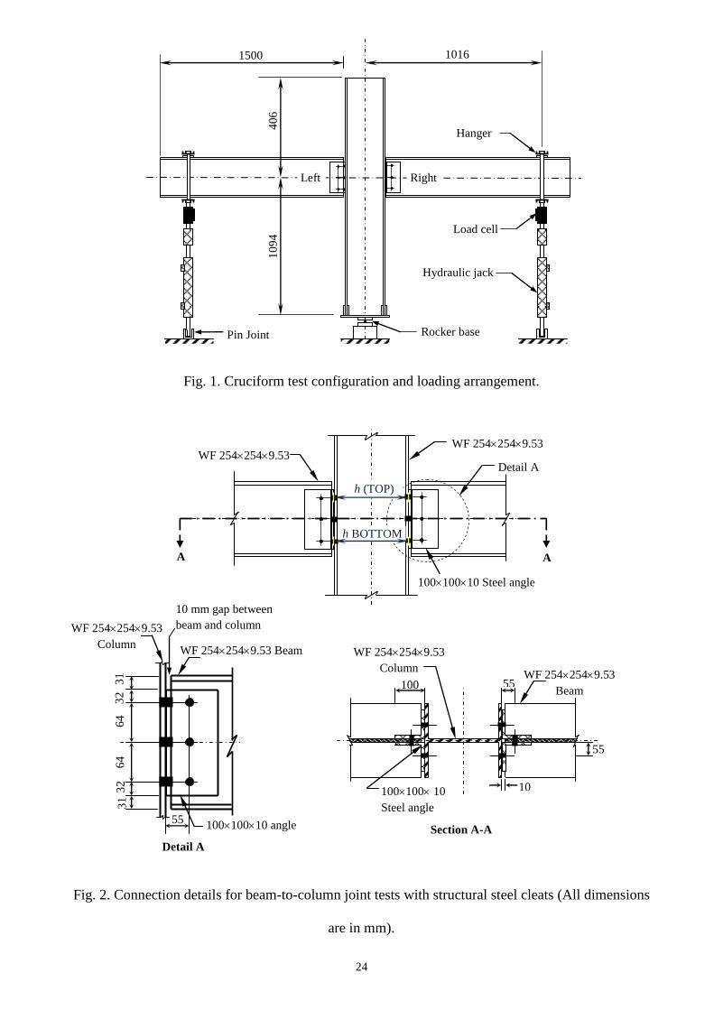
and joints in a way that they could experience in a real frame. The column and beam sections are of
size 254×254×9.53 mm [2], and are 1.5 m long. The shape is a wide flange section from the Pultex®
SuperStructural 1525 series [2]. Steel web cleats are 192 mm long and cut from equal leg-angle of size
100×100×10 mm. A gap of 10 mm is kept between the end of the beam and the flange faces of the
column to facilitate rotation of the beams. The use of web cleats together with this gap constitutes a
nominally pinned joint. This type of joint is expected to transmit negligible moment across connecting
components, and allows acceptable unrestrained relative rotations between framing elements.
Testing of the 12 joints is divided into two batches of six, one with three and the other with two bolts
per cleat leg. The two bolted configuration is same except that the middle of the three bolts is absent.
As seen in Figs 1 to 4 the bolts are placed in a line parallel to the connection shear force from the
beam loading. Specimens with three bolts are denoted by label Wmj254_3M16_ST and
Wmj254_2M16_ST for the two-bolted configuration. For example, Wmj254_3M16_ST defines the
test joint as Web-cleated with a major axis column, 254×254×9.53 mm wide flange sections having a
single row of 3 M16 bolts with Steel web cleats. As Fig. 1 shows the centreline of the beams is at a
vertical height of 1094 mm from the base of the column. This height is controlled by the dimensions
of hydraulic tension jacks and is sufficient to accommodate a downward stroke of 150 mm. To ensure
both beams are subjected to same bending moments and shear forces the column section is placed on
a steel rocker base fixture, having rotational freedom, as illustrated in Fig. 1.
6
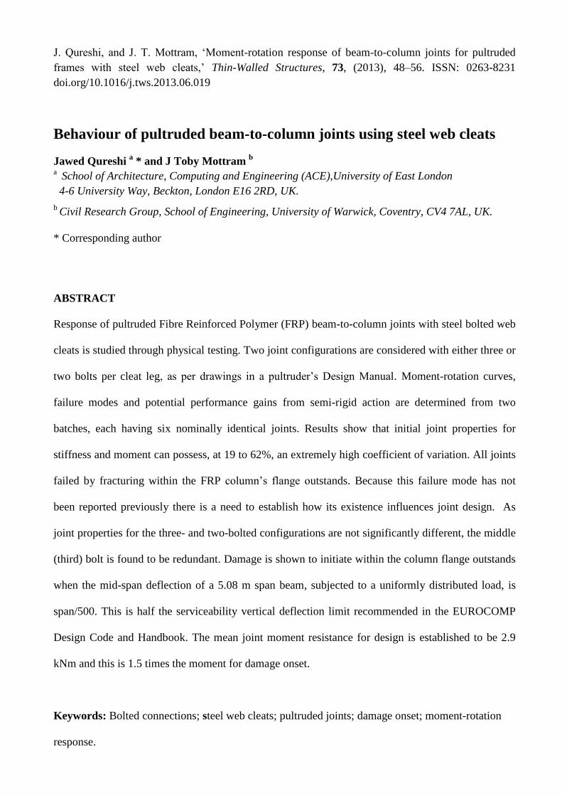
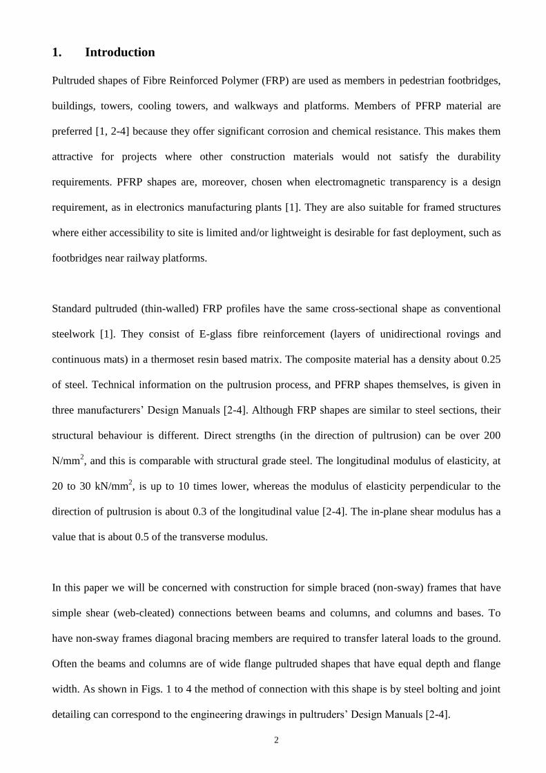
2.1 Connection Details
Connection details shown in Fig. 2 are in accordance with Page 19-7 in the Strongwell Design
Manual [3], and the minimum requirements for bolted connection geometries in the 2010 ASCE pre-
standard [12]. Bolting uses standard size steel bolts of M16 grade 8.8 with 35 mm diameter by 3 mm
thick steel washers. The shank bearing into FRP material (inner side of holes in beams and column) is
plain to avoid any localised deformation from thread indentations. An important difference in this test
series, from previous [8, 13], is that the bolt hole clearance in web of beams is kept minimal. To do
this a CNC machine was used to drill holes of exactly 16 mm diameter through beam webs and
connecting cleat legs. One reason that hole clearance cannot be eliminated altogether [10] is that the
diameter of M16 bolts available in market ranges from 15.6 to 15.9 mm. The reason for tight-fitting
holes on the beam side was to limit joint rotation due to slippage and to develop the maximum joint
stiffness that could be found in the field.
The presence of bolt hole clearance leads to connection slip, and thus, slip rotation. This rotation is
highly dependent on where the bolts are placed with respect to the hole. Although it has a positive
effect in the form of increase in overall rotations [7-8, 13], it cannot be relied upon. In the field, bolts
could be located in such a way that it might not happen. Minimising clearance on beam side also
ensures that the rotation generated is predominantly due to prying action. Since having clearance
holes on the column side does not influence overall rotations, a clearance of 2 mm was present for the
bolt holes drilled in the column flange outstands. It also makes the assembly of the joint
straightforward.
2.2 Loading procedure
Load is transferred into a beam through a hanger assembly and a 12.7 mm diameter ball bearing
placed at the centre of the steel loading plate. Two hydraulic tension jacks apply the point load. The
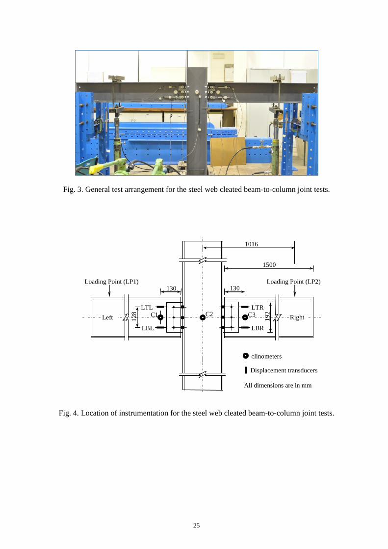
load applied in this manner ensures vertical loading. The general test arrangement is shown in Fig. 3.
Load is applied at a distance of 1.016 m from centreline of the column. This distance is governed by

7
anchor points on the strong floor having spacing of 408 mm centres. The applied load on the Left and
Right sides is measured via two tension load cells having capacity of 9 kN with a resolution of 0.01
kN. Two manual hydraulic pumps are used to operate the jacks. The rocker base fixture ensures equal
load increments to the beams.
Joint moment is established by the vertical load times the lever arm distance of 1016 mm taken from
the loading point to the centreline of the column member. The reason for taking moment from
centreline of the column, rather than the plane separating the column flange and web cleats to loading
point is that the column web panel constitutes part of the joint. Eurocode 3 Part 1-8 [14] provides a
clear description of what a joint is. It defines the joint to be the zone where two or more members are
attached together. Concerning the test configuration in Figure 1 the beam-to-column joint consists of
all the material (e.g. beam and column web and columns flange outstands) and connection
components (i.e. bolting and web cleats) that lie between the pair of clinometers measuring the joint
rotation.
The specimen is loaded under load control in 0.25 kN increments. A time interval of five minutes is
maintained between two increments to make visual inspection and to take measurements. Readings
are taken immediately after load is applied and five minutes later. This procedure allows onset and
progressive material damage to be observed. Load is continuously increased until the joint rotation
increases significantly without noticeable change in the moment or it is deemed that specimen
instability might occur. Each specimen is unloaded and reloaded at overall joint rotations of 20 and
30 mrad to record permanent rotations. The specimens are unloaded at the end of the testing and final
permanent rotation noted. Further details on the test method are given in Qureshi and Mottram [10].
To ensure connecting elements in the joint are in firm contact, bolts are tightened to snug-tight
condition. This condition is achieved when bolts will not turn any further after full effort of a worker
using an ordinary spud wrench.

8
2.3 Instrumentation
Typical instrumentation to measure joint properties is shown in Fig. 4. Rotations of beams are
measured by clinometers C1 and C3, placed at a distance of 130 mm from the end of the beam
adjacent to the column flange. Column rotation is measured by C2, and the difference between beam
and column rotations give the Left and Right joint rotations. The ‘secondary’ rotation due to relative
connection slippage between a beam’s web and the pair of cleats is determined, using the geometric
relationship in Qureshi and Mottram [10], via displacements from the four transducers LTL, LBL,
LTR and LBR. The positions of these transducers are seen in Fig. 4. The displacements are measured
to a resolution of 0.01 mm and the rotation to 0.02 mrad (linear to 1% over a 10o range).
Qureshi and Mottram [10] confirmed that the joints with PFRP web cleats fail by delamination,
which is seen first at the top of cleats and near the fillet radii [7, 8]. With steel web cleats, the
pultruded members are likely to fail because cleats are no longer the weakest link. This is because
steel has yield strength (275 N/mm2) that is many times higher than the through-thickness tensile
strength of the FRP and a modulus of elasticity 10 to 20 times higher. Steel cleats will have a much
higher resistance to the low level of prying action. As a result the tension force (at top bolt level)
from the prying action causes the column flange outstands to undergo significant flexural
deformation. To monitor this joint deformation, which was not noticeable when equivalent cleats
were PFRP [10], the horizontal distance between the outer surfaces of the column flanges at the level
of the top and bottom bolts is measured. This result is given by hprying – h, where h is the undeformed
depth (see Fig. 2) and hprying is the deformed depth (refer to Fig. 5). The measurements are taken by
means of a vernier calliper at each load increment, and at the start and end of the test.
3. Results and discussion
Tables 1 and 2 present joint properties for the two batches of specimens having three- and two-bolted
joint configurations. The slip rotation is deducted from the overall rotation of the joints in these
tables. Therefore, the properties reported are due to the effect of the prying action alone. Minimum

9
and maximum values for a particular column are highlighted using bold font. Specimen labels are
given in column (1), which also identify if the joint is on the Left or Right side. For the linear
moment-rotation response the initial joint properties are given in columns (2) to (4). They are the
initial moment (Mi), initial joint rotation (i) and initial joint stiffness Si (= Mi/i). Similarly, the
equivalent properties for onset of damage, which has a specific definition introduced later, are given
in columns (5) to (7) by Mj, j and (Sj = Mj/j). Columns (8) to (9) give the maximum moment (Mmax)
and maximum rotation (max). At the bottom of Tables 1 and 2 the mean and coefficient of variation
(CV) of each joint property are presented.
3.1 Joint Properties
Prior to giving a discussion on damage onset, the initial and maximum test results will be discussed.
For the Wmj254_3M16_ST batch, the moment-rotation remains linear up to a mean Mi of 0.92 kNm.
The minimum and maximum initial moments in column (2) of Table 1 are 0.68 and 1.27 kNm, and
the six joints give a relatively high coefficient of variation (CV) of 29%. Initial rotation (i) is also
highly variable with test results ranging from 0.7 to 4.1 mrad. The mean rotation of 2.3 mrad has a
very high CV of 62%. Due to the high variation in these initial properties the initial joint stiffness has
a CV of 47%. From column (4) of Table 1 the mean, minimum and maximum Sis are 502, 302 and
913 kNm/rad. From the data in columns (8) and (9) it is observed that Mmax and max do not change
significantly for the Wmj254_3M16_ST batch; and these properties have the relatively low CVs of
1.4% and 13%. The mean Mmax is 3.4 kNm and the mean max of 52 mrad.
From the Wmj254_2M16_ST batch the moment-rotation response is found to be linear to a mean
initial moment of 0.73 kNm. Mi in column (2) of Table 2 ranges from 0.56 to 0.87 kNm, giving a CV
of 19%. The corresponding mean initial rotation in column (3) is 1.4 mrad, minimum and maximum
is are found to be 0.8 and 2.2 mrad. Initial joint rotational stiffness (Si) has a mean of 577 kNm/rad

10
and a CV of 38%. This is similar to the Wmj254_3M16_ST batch results in column (4) of Table 1,
and shows a large variation in initial joint properties. From Table 2 the mean Mmax is 3.82 kNm and
mean max is 64 mrad. As with the three bolted joint case, it is noteworthy that the maximum joint
properties in columns (8) and (9) do not vary much, giving relatively small CVs of 3.5% and 6%.
Comparison of Table 1 and 2 suggests that the joint properties of two- and three-bolted configuration
are not much different with marginally higher maximum moment and rotation in former case. This
finding shows that the third bolt is not needed to resist the effect of the beam loading. This slight
increase in the joint properties is by no means an indication of better performance of two- compared
with three-bolted configuration. The maximum joint properties depend on when the test was stopped,
which again relies on either instability or ultimate failure of the specimen under consideration.
3.2 Damage onset
It is not straightforward with steel web cleats to precisely define the joint rotation (j) for damage
onset. With similar cleating of FRP, Qureshi and Mottram [10] found that damage initiated as
delamination cracking was easily seen by the human eye at the top of pultruded cleats. With steel
cleats failure occurs within the web-flange junction of the column. For this failure mode damage
onset is defined as the point on the moment-rotation curve when audible noises, emanating from
inside the column flanges, were first heard. Additional evidence for this stage establishing damage is
that the M- response was noticeably non-linear and the column flanges were experiencing a
significant outward flexural deformation, in line with the top bolt level.
Fig. 5 shows the extent of this flange deformation (hprying (TOP) – h (TOP)) and (hprying (BOTTOM) –
h (BOTTOM)) when in test Wmj254_3M16_ST1.2 had reached 50 mrad. All specimens failed by
cracking in web-flange junction of the column near top bolt level and progressed downwards to
bottom bolt level. Due to prying action, column flange outstands deflect outwards at the top bolt level
and there was no change in the section’s depth at the bottom bolt level. It is found that the steel cleats
did not noticeably deform or have yielding. To establish the extent of permanent damage, one of the
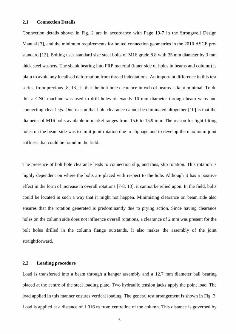
11
failed columns was sectioned, just above the middle bolt level. On one side of the web, the flange
outstands were cut off to expose the extent of internal damage in the form of delamination cracks. As
Fig. 6 shows there is fracturing in the region of the web-flange junction and significant delamination
in the flanges. The presence of these internal damage highlights that the stiffness of the column will
have continually reduced as PFRP damage progressed. It is this progressive deterioration that helps to
explain the non-linear M- response, such as seen by the test curves in Figs. 8 and 9. At the end of a
test the internal fracturing was seen to reach the top free end of column, which is 280 mm from the
top flange of the beams.
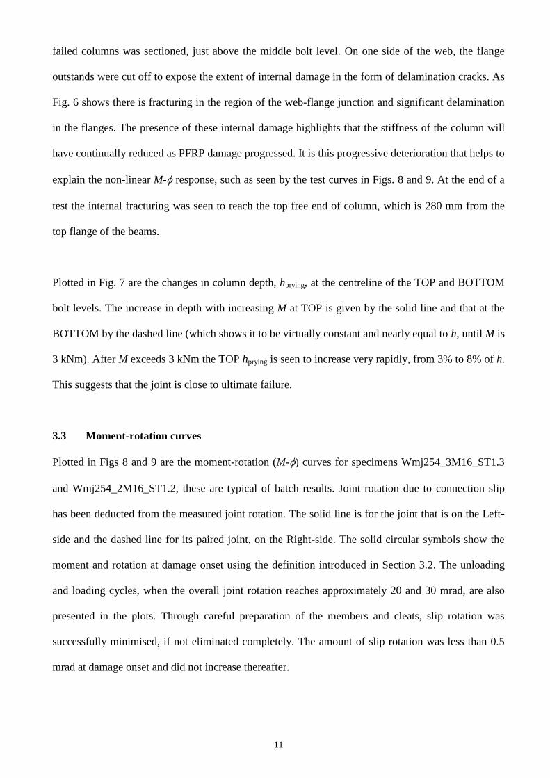
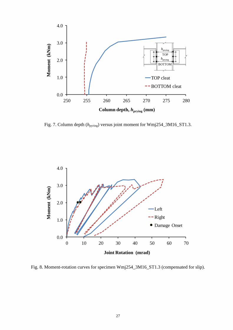
Plotted in Fig. 7 are the changes in column depth, hprying, at the centreline of the TOP and BOTTOM
bolt levels. The increase in depth with increasing M at TOP is given by the solid line and that at the
BOTTOM by the dashed line (which shows it to be virtually constant and nearly equal to h, until M is
3 kNm). After M exceeds 3 kNm the TOP hprying is seen to increase very rapidly, from 3% to 8% of h.
This suggests that the joint is close to ultimate failure.
3.3 Moment-rotation curves
Plotted in Figs 8 and 9 are the moment-rotation (M-) curves for specimens Wmj254_3M16_ST1.3
and Wmj254_2M16_ST1.2, these are typical of batch results. Joint rotation due to connection slip
has been deducted from the measured joint rotation. The solid line is for the joint that is on the Left-
side and the dashed line for its paired joint, on the Right-side. The solid circular symbols show the
moment and rotation at damage onset using the definition introduced in Section 3.2. The unloading
and loading cycles, when the overall joint rotation reaches approximately 20 and 30 mrad, are also
presented in the plots. Through careful preparation of the members and cleats, slip rotation was
successfully minimised, if not eliminated completely. The amount of slip rotation was less than 0.5
mrad at damage onset and did not increase thereafter.

12
The saw-tooth shape to the M- curves in Figs 8 and 9 is the result of taking readings straight after a
load increment was applied, and 5 minutes later. The change shows the extent of relaxation in this
short period of time due to damage progression. The more noticeable drop in moment, after M
exceeds 2.5 kNm, does suggest that the Left and Right joints are now experiencing significant
material damage. To further support this behaviour, the moment reduction becomes more prominent
as the Left and Right joint rotations approach their max.
Although both M- curves in Fig. 8 remain linear up to a moment of 0.70 kNm the value of Si (from
Table 1) on the Left side, at 913 kNm/rad, is twice that for the Right side, at 444 kNm/rad. A
physical explanation for this considerable difference cannot be given. It is noted that because both Mi
and i are at the low end of their measurement scales this could be a contributing factor. The extent
of permanent deformation for Wmj254_3M16_ST1.3 can be observed from the loading and
unloading cycles presented in Fig. 8. For the first unloading stage at 20 mrad there was a permanent
rotation in both joints of 5 mrad. On reloading to the same M, the Right side rotated to 33 mrad and,
because there was less deterioration, the Left joint’s rotation was 25 mrad. This suggests reloading
causes further material degradation inside the column flanges, and it was now impractical to maintain
‘identical’ joint rotations on both sides. The specimen was, again, unloaded and reloaded with the
results that the permanent rotations were 6 and 11 mrad on Left and Right sides. No obvious peak
moment was established and further loading was stopped when joint deformation was deemed to be
excessive; termination of additional loading stages therefore gave the readings in columns (8) and (9)
of Table 1 for Mmax and max.
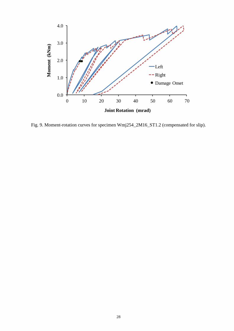
Fig. 9 gives the equivalent M- characteristics for Wmj254_2M16_ST1.2, again, after taking into
account secondary slip rotation. The response of this two-bolt configuration is found to be similar to
three-bolted situation. Wmj254_2M16_ST1.2 has a linear M- to a moment (Mi) of 0.56 kNm. This
is followed by a non-linear response that is directly linked to outward flexural deformation of the
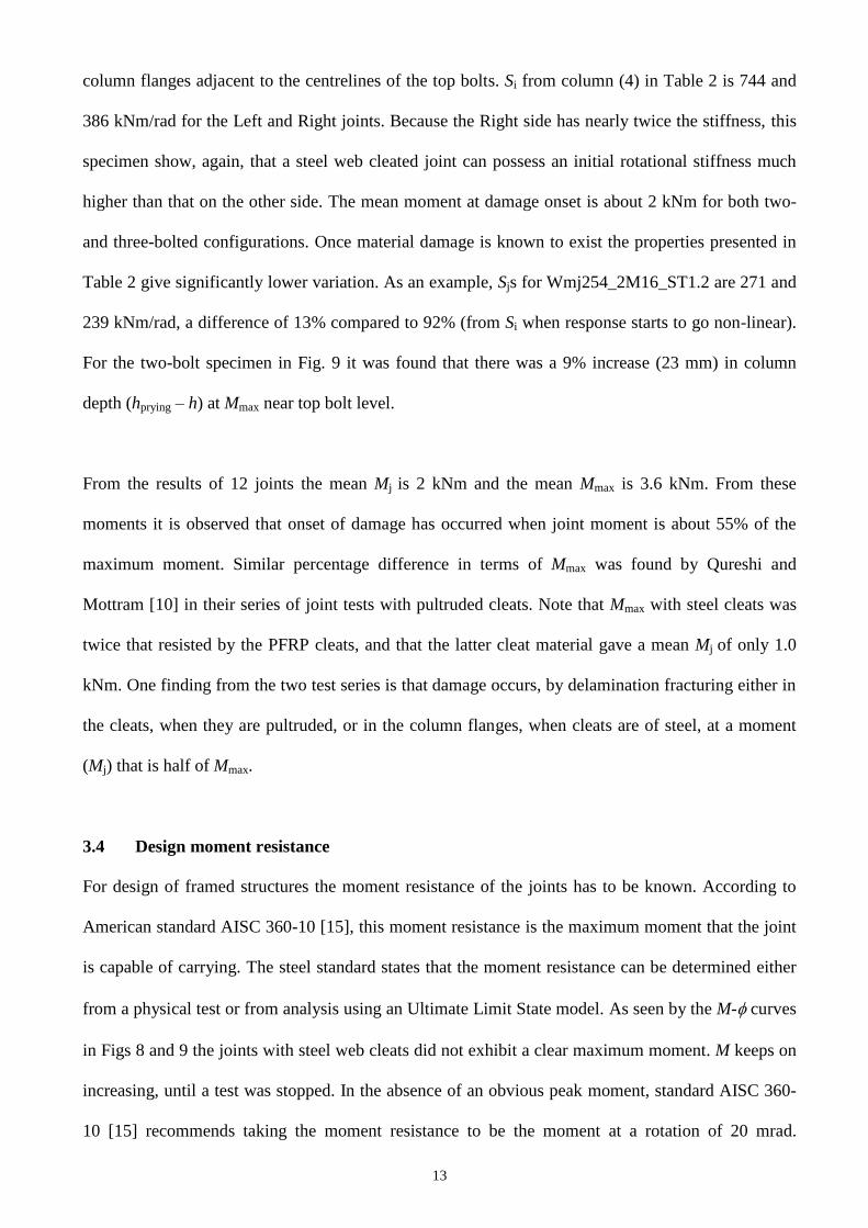
13
column flanges adjacent to the centrelines of the top bolts. Si from column (4) in Table 2 is 744 and
386 kNm/rad for the Left and Right joints. Because the Right side has nearly twice the stiffness, this
specimen show, again, that a steel web cleated joint can possess an initial rotational stiffness much
higher than that on the other side. The mean moment at damage onset is about 2 kNm for both two-
and three-bolted configurations. Once material damage is known to exist the properties presented in
Table 2 give significantly lower variation. As an example, Sjs for Wmj254_2M16_ST1.2 are 271 and
239 kNm/rad, a difference of 13% compared to 92% (from Si when response starts to go non-linear).
For the two-bolt specimen in Fig. 9 it was found that there was a 9% increase (23 mm) in column
depth (hprying – h) at Mmax near top bolt level.
From the results of 12 joints the mean Mj is 2 kNm and the mean Mmax is 3.6 kNm. From these
moments it is observed that onset of damage has occurred when joint moment is about 55% of the
maximum moment. Similar percentage difference in terms of Mmax was found by Qureshi and
Mottram [10] in their series of joint tests with pultruded cleats. Note that Mmax with steel cleats was
twice that resisted by the PFRP cleats, and that the latter cleat material gave a mean Mj of only 1.0
kNm. One finding from the two test series is that damage occurs, by delamination fracturing either in
the cleats, when they are pultruded, or in the column flanges, when cleats are of steel, at a moment
(Mj) that is half of Mmax.
3.4 Design moment resistance
For design of framed structures the moment resistance of the joints has to be known. According to
American standard AISC 360-10 [15], this moment resistance is the maximum moment that the joint
is capable of carrying. The steel standard states that the moment resistance can be determined either
from a physical test or from analysis using an Ultimate Limit State model. As seen by the M- curves
in Figs 8 and 9 the joints with steel web cleats did not exhibit a clear maximum moment. M keeps on
increasing, until a test was stopped. In the absence of an obvious peak moment, standard AISC 360-
10 [15] recommends taking the moment resistance to be the moment at a rotation of 20 mrad.

14
Applying this approach the mean joint moment resistance, for use in design, is found to be 2.9 kNm.
Pultex® SuperStructural wide flange shapes have a flexural strength of 300 N/mm2 [2] and the
major-axis second moment of area (I) is 8.34x107 mm
4 for the 254×254×9.53 mm section. Using
conventional engineering beam theory the moment resistance of the section to (linear elastic) rupture
is 198 kNm, which is > 60 times the joints’ mean moment resistance (2.9 kNm).
3.5 Failure when cleats are of steel
The extent of flexure in the column flange outstands is shown in Figs 10(a) to 10(c). Fig. 10(a)
indicates the localised nature of this column deformation. With respect to a steel ruler, pressed
against the undeformed flange below the bottom bolt level, Fig. 10(b) shows the degree of
deformation for the geometric test property hprying. Because the steel cleats possess relatively high
strength and stiffness, their deformation from transmitting moment and shear force is not discernable.
Owing to the layered construction of pultruded material, cleats of FRP are susceptible to
delamination failure caused by prying where tensile stresses in the through-thickness direction are
highest [10]. As this study shows when steel replaces pultruded FRP, joint failure is shifted from the
web cleating [10] into the column. At Mmax the flanges deflected outwards resulting in 20 to 24 mm
increase in overall depth of the column at top bolt level. This can be seen in Fig. 10(c) and this
localised column deformation represents an 8 to 9% increase in overall column depth.
Manufacturers of pultruded shapes do offer some guidance for beam members having PFRP web-
cleated joints [2-4]. Strength information for the web-cleated joints is reported, but not for the
moment resistance. It is based on the three modes of failures being, bearing of cleat material near
fastener holes, or shear failure at the heel of the angle, or shear failure in bolting [1]. None of these
failure modes were observed with either FRP [10] or steel cleats in the test series presented in this
paper. Given that there are no specific guidelines for steel cleats there is a need for a revision of the
Design Manuals [2-4] to account for the actual modes of failure and how they affect joint
performance.

15
3.6 Serviceability and performance gain due to semi-rigid action
In order to take advantage of semi-rigid action the joint has to possess sufficient end rotation prior to
onset of material damage, as this could detrimentally affect structural integrity during the structure’s
service life. Applying the damage criterion introduced earlier in this paper the mean j, from column
(6) of Tables 1 and 2, is 7.7 mrad, having a CV of 9.8% and standard deviation of 0.75 mrad. Hence,
using the expression of Mean - 1.82 SD (Annex D of [16]) the characteristic rotation at damage
onset is 6.3 mrad. For a simply supported beam subjected to a Uniformly Distributed Load (UDL)
this characteristic damage rotation of 6.3 mrad equates to a mid-span deflection of span/500. Note
that in the EUROCOMP Design Code and Handbook [17] the recommended vertical deflection limit
is span/250 for a Serviceability Limit State.
Semi-rigid action may be utilised in the design of PFRP beams to achieve a performance gain.
Turvey [18] developed closed-form expressions to calculate the response of a ‘semi-rigid’ beam, with
respect to the identical simply supported beam, by means of performance indices. These indices are
for the reduction in beam deflection, the increase in load-carrying capacity and/or the increase in
span for the same deflection. The use of these equations requires knowledge of the rotational stiffness
of the semi-rigid joints and its variation. Because Si from Tables 1 and 2 is unreliable for the reason
already discussed, this stiffness measure cannot be used. Although Turvey [18] recommends using Si
with his formulae, the authors advocate that the rotational stiffness should be the secant value at
damage onset. This is because Si exhibits a too high CV (41% for joints in this study) and cannot be
reliably used. The Sjs in Tables 1 and 2 are more reliable; especially since the batch of 12 joints have
a CV of 10%.
To evaluate the performance gain, from Sj > zero, let us assume the beam is shear rigid and subjected
to a uniformly distributed load. Fig. 11 presents a plot to show the potential benefit obtained from the
semi-rigid action. The abscissa scale is for span-to-depth ratios from 0 to 40, and the ordinate is for
16
the load enhancement index (Q) which represents the additional load for a specified mid-span
deflection limit. A step-by-step procedure to calculate Q for a span-to-depth ratio of 20 is given in
the Appendix. The plot in Fig. 11 shows that Q increases with more load gained as the span-to-depth
ratio increases. For example, exploiting the mean Sj (266 kNm/rad) from Tables 1 and 2, for the steel
web cleat details in Fig. 2, leads to a load increase of 22% and 42% for the span-to-depth ratios of 20
and 40, respectively. Owing to the linear elastic and small displacement assumption in the analytical
treatment [18], the load enhancement (Q) and deflection reduction () indices are inversely
proportional to each other. This means there will be reductions of 0.82 and 0.70 to the mid-span
deflection at these two span-to-depth ratios. This preliminary evaluation demonstrates that either a
reduction in mid-span deflection or an increase in UDL is practical if the rotational stiffness of
practical joint details is accounted for. The initial or secant joint rotational stiffness under service
loading can be favourably exploited to achieve performance gains in terms of deflection reduction, or
load or span enhancement.
4. Concluding remarks
Beam-to-column joints for Pultruded Fibre Reinforced Polymer (PFRP) members with bolted steel
web cleats for a nominally pinned joint are characterised through testing two batches of six nominally
identical joints. One batch had three bolts per cleat leg and the second had the middle bolt of the
three removed. Because test results showed that there is no significant difference between two
batches, the authors recommend that the third (middle) bolt detailing can be removed from the
engineering drawing in the Strongwell Design Manual [3].
For the preparation of design guidelines the following key findings from an evaluation of the test
results are of relevance:

17
It is found that by having web cleats of steel the onset of damage will occur within the
pultruded FRP column flange outstands. Such FRP failure is initiated by prying action
causing considerable flexural deformation of the column flange outstands. None of the Design
Manuals [2-4] report this type of failure. Owing to the field application of steel cleats in PFRP
frames there is a need to include this type of failure mode and its design implications when
revising the manuals.
To characterise the ‘stiffest’ joint in practice, the specimens were fabricated with tight-fitting
bolt holes between the pair of steel cleat legs and the web in a beam member. Because ‘off-
the-shelf’ M16 steel bolts have a shank diameter of 15.6 to 15.9 mm the joint rotation due to
connection slip between cleats and beam was not entirely eliminated. Its magnitude was
found to be only 0.5 mrad at damage onset, and it did not increase significantly thereafter. All
rotation results presented are compensated for slip rotation to ensure that the rotation at
damage onset is its lowest possible field value.
The linear region on the moment-rotation curves is relatively small and non-linearity in joints’
response is found when rotation is more than 4 mrad. All initial moment, rotation and
stiffness values show variability with coefficients of variation of 28%, 62% and 41%,
respectively, with stiffnesses (ranging from 302 to 913 kNm/rad) based on combined results
from 12 joints. It is found that the unreliability of these initial joint properties means they
cannot be used to adequately represent the joints in real frames.
Taking the characteristic value of joint rotation at damage onset as 6.3 mrad, it has been
shown that (delamination) damage could occur within the column member when the mid-span
deflection of a beam with a uniformly distributed load is span/500. This is half the
serviceability vertical deflection limit recommended in the EUROCOMP Design Code and
Handbook [17]. The rotation at damage onset is likely to increase (but not guaranteed) when
bolting has clearance holes of 1 mm [4] or larger [2-3].
By using Turvey’s [18] closed form equations with the joint rotational stiffness at damage
onset a performance gain of 22% is identified in terms of the increase in load carrying
18
capacity of a shear rigid pultruded beam having a uniformly distributed load and a span-to-
depth ratio of 20. This load increase is relative to the deflection of the same beam being
simply supported. Load enhancement will increase with increasing span-to-depth ratio, and
vice versa.
When a joint test does not show a clear peak moment in the moment-rotation response, AISC
360-10 [15] specifies that the value corresponding to a rotation of 20 mrad should be used.
For the purpose of design the mean moment resistance from the 12 joints is 2.9 kNm. This
moment is 1.5 times the moment at damage onset (2 kNm), and only 1.5% of the section
moment of resistance (198 kNm) when flexural strength of the Pultex® SuperStrucutral
pultruded shape is taken to be 300 MPa [2].

19
Acknowledgements
The authors wish to thank EPSRC (Connections and Joints for Buildings and Bridges of Fibre
Reinforced Polymer (EP/H042628/1)) and Access Engineering and Design (supplier of Creative
Pultrusions product Pultex in the UK), Telford, UK, for project funding and supplying FRP shapes,
respectively. Assistance from technical staff (Mr Colin Banks (Civil Engineering), Mr Rob Bromley
(workshop) and Mr Graham Canham (photographer)), in the School of Engineering, is acknowledged
as being invaluable to the quality and future impact of the research.
Appendix for calculation of load enhancement index (Q)
Load enhancement index (Q) is calculated according to the procedure given in Turvey [18]. We
shall consider a beam with a uniformly distributed load. In order to calculate the load enhancement
index (Q) the deflection reduction index () has first to be determined from:
2δ
4 2
1 k
k k
A.1
where
k2 From Table 1 [18] is 10.
k4 From Table 1 [18] is 5.
Dimensionless rotational flexibility of the beam end connection given by (ELI/KL), where
EL Longitudinal modulus of elasticity for pultruded beam (is 27.6 kN/mm2 from Creative
Pultrusion Design Manual [2])
I Major-axis second moment of area of beam cross-section (is 8.34x107 mm
4 from
Creative Pultrusion Design Manual [2])
K Rotational stiffness of the beam end connection [18] (is Sj = 266 kNm/rad from the
mean joint rotational stiffness from the 12 joints in Tables 1 and 2)
L Beam span is 5080 mm (based on a span-to-depth ratio of 20 for 2542549.53
shape).

20
Q is calculated from the inverse of Equ. (A.1):
Q
δ
1
(A.2)
Assuming the PFRP beam is shear-rigid, , (A.1) and Q (A.2) are calculated to be:
7
6
27.6 1000 8.34 101.7
266 10 5080
LE I
KL
2δ
4 2
1 1 10 1.70.82
5 10 1.7
k
k k
Q
δ
1 11.22
0.82

21
References
[1] Bank LC. Composites for construction: Structural design with FRP materials. John Wiley &
Sons, New Jersey, 2006.
[2] Anonymous. The new and improved Pultex pultrusion design manual. Creative Pultrusions
Inc., Alum Bank, PA. (www.creativepultrusions.com/library.html) (July 18, 2013).
[3] Anonymous. Strongwell design manual. Strongwell, Bristol, VA. (www.strongwell.com/)
(July 18, 2013).
[4] Anonymous. Fiberline design manual for structural profiles in composite materials. Fiberline
Composites A/S, Kolding, Denmark. (www.fiberline.com/read-more-about-fiberline-online-
tools) ()July 18, 2013.
[5] Turvey GJ. Moment–rotation tests on bolted end connections in pultruded GRP beams-tests
with stainless steel cleats and an assessment of their performance relative to GRP cleats. In:
Proceedings of the Ninth European Conference on Composite Materials (ECCM 9: From
Fundamentals to Exploitation), Brighton, 4-7 June 2000.
[6] Mottram JT. Connection tests for pultruded frames. Research Report CE47, Civil Engineering
Group, School of Engineering, University of Warwick, Coventry, U.K, 1994.
[7] Mosallam AS. State-of-the-art on connections for pultruded frame structures. In: Connecting
with Pultrusion, Proceedings of the Fourth EPTA World Pultrusion Conference, European
Pultrusion Technology Association, Harderwijk, The Netherlands, 1998.
[8] Mottram JT, Zheng Y. Further tests on beam-to-column connections for pultruded frames:
Web-cleated. J Compos Constr 1999;3(1):3-11.
[9] Mottram JT, Zheng Y. Further tests on beam-to-column connections for pultruded frames:
Flange-cleated. J Compos Constr 1999;3(3):108–116.
[10] Qureshi J, Mottram JT. Moment-rotation response of nominally pinned beam-to-column
joints for frames of pultruded fibre reinforced polymer. Eng Struct 2012 (under review).
[11] Turvey GJ, Cooper C. Review of tests on bolted joints between pultruded GRP profiles. P I
Civil Eng-Str B 2004;157(3):211-233.
[12] Pre-standard for Load and Resistance Factor Design (LRFD) of pultruded Fiber Reinforced
Polymer (FRP) structures (Final). American Composites Manufacturers Association,
American Society of Civil Engineers, November 9, 2010.
[13] Mottram JT. Nominally pinned connections for pultruded frames. In Clarke JL editor.
Structural Design of Polymer Composites - EUROCOMP Design Code and Handbook, S. &
F. N. Spon, London, 1996. p.703-718.

22
[14] BS EN 1993-1-8:2005. Eurocode 3: Design of steel structures - Part 1-8: Design of joints.
British Standards Institution, United Kingdom, 2005.
[15] AISC 360-10. Specification for Structural Steel Buildings. American Institute of Steel
Construction. Chicago, Illinois, USA, June 22, 2010.
[16] BS EN 1990:2002. Eurocode 0 - Basis of structural design. British Standards Institution,
United Kingdom, 2002.
[17] Clarke JL (Editor). Structural design of polymer composites - EUROCOMP design code and
handbook. E. & F.N. Spon, London, 1996.
[18] Turvey GJ. Analysis of pultruded GRP beams with semi-rigid end connections. Compos
Struct 1997;38(4):3-16.

23
Table 1. Joint properties for beam-to-column joint test Wmj254_3M16_ST (compensated for slip)
Specimen label
(1)
Mi
(kNm)
(2)
i
(mrad)
(3)
Si = Mi/i
(kNm/rad)
(4)
Mj
(kNm)
(5)
j
(mrad)
(6)
Sj = Mj/j
(kNm/rad)
(7)
Mmax
(kNm)
(8)
max
(mrad)
(9)
Wmj254_3M16_ST1.1 (Left) 1.25 4.1 302 1.97 7.3 271 3.42 50
Wmj254_3M16_ST1.1 (Right) 1.27 4.0 316 1.99 7.7 258 3.44 59
Wmj254_3M16_ST1.2 (Left) 0.80 1.2 649 2.04 6.4 316 3.43 51
Wmj254_3M16_ST1.2 (Right) 0.83 2.2 386 2.06 7.7 268 3.44 55
Wmj254_3M16_ST1.3 (Left) 0.68 0.7 913 2.02 6.4 318 3.34 40
Wmj254_3M16_ST1.3 (Right) 0.71 1.6 444 2.04 7.9 259 3.35 57
Mean of 6 0.92 2.3 502 2.02 7.2 282 3.40 52
CV 29% 62% 47% 1.7% 9.2% 9.9% 1.4% 13%
Table 2. Joint properties for beam-to-column joint test Wmj254_2M16_ST (compensated for slip)
Specimen label
(1)
Mi
(kNm)
(2)
i
(mrad)
(3)
Si = Mi/i
(kNm/rad)
(4)
Mj
(kNm)
(5)
j
(mrad)
(6)
Sj = Mj/j
(kNm/rad)
(7)
Mmax
(kNm)
(8)
max
(mrad)
(9)
Wmj254_2M16_ST1.1 (Left) 0.76 0.8 896 1.92 7.6 254 3.74 59
Wmj254_2M16_ST1.1 (Right) 0.75 1.9 398 2.15 8.5 252 3.71 61
Wmj254_2M16_ST1.2 (Left) 0.56 0.8 744 2.03 7.5 271 3.98 64
Wmj254_2M16_ST1.2 (Right) 0.56 1.4 386 2.03 8.5 239 4.00 68
Wmj254_2M16_ST1.3 (Left) 0.86 1.3 646 2.03 8.0 254 3.74 62
Wmj254_2M16_ST1.3 (Right) 0.87 2.2 393 2.03 8.8 231 3.74 69
Mean of 6 0.73 1.4 577 2.03 8.2 250 3.82 64
CV 19% 41% 38% 3.5% 6.7% 5.5% 3.5% 6%
24
Fig. 1. Cruciform test configuration and loading arrangement.
Fig. 2. Connection details for beam-to-column joint tests with structural steel cleats (All dimensions
are in mm).
WF 2542549.53
Beam
WF 2542549.53
Column
100100 10
Steel angle
Section A-A
10
100 55
55
Load cell
Hydraulic jack 1
09
4
40
6
1500 1016
Hanger
Pin Joint Rocker base
Right Left
WF 2542549.53
Column
10 mm gap between
beam and column
WF 2542549.53 Beam
55
32
31
64
64
31
32
10010010 angle
Detail A
10010010 Steel angle
WF 2542549.53
A A
WF 2542549.53
Detail A
h (TOP)
h BOTTOM
25
Fig. 3. General test arrangement for the steel web cleated beam-to-column joint tests.
Fig. 4. Location of instrumentation for the steel web cleated beam-to-column joint tests.
C2 C1 C3
130
LTR
LBR
LTL
LBL
12
8
19
2
1016
1500
Loading Point (LP2)
clinometers
Displacement transducers
All dimensions are in mm
Loading Point (LP1) 130
Right Left

26
Fig. 5. Close-up of Left and Right joints in Wmj254_3M16_ST1.2 when Mmax is applied.
Fig.6. Internal fracture pattern in column section (cut above middle bolt hole level).
Web
Web-flange junction Web-flange junction
Delamination in flange
Flange Flange
hprying (BOTTOM)
hprying (TOP)
Column
Beam Beam
Steel web cleat Steel web cleat
27
0.0
1.0
2.0
3.0
4.0
250 255 260 265 270 275 280
Mom
ent
(k
Nm
)
Column depth, hprying (mm)
TOP cleat
BOTTOM cleat
hprying
TOP
hprying
BOTTOM
Fig. 7. Column depth (hpyring) versus joint moment for Wmj254_3M16_ST1.3.
0.0
1.0
2.0
3.0
4.0
0 10 20 30 40 50 60 70
Mom
ent
(k
Nm
)
Joint Rotation (mrad)
Left
Right
Damage Onset
Fig. 8. Moment-rotation curves for specimen Wmj254_3M16_ST1.3 (compensated for slip).
28
0.0
1.0
2.0
3.0
4.0
0 10 20 30 40 50 60 70
Mom
ent
(k
Nm
)
Joint Rotation (mrad)
Left
Right
Damage Onset
Fig. 9. Moment-rotation curves for specimen Wmj254_2M16_ST1.2 (compensated for slip).

29
Fig. 10. Different views of localised column deformations when joints had failed: (a) Outward
flexure of column flanges; (b) Flexure of column flanges with respect to a vertically placed ruler; (c)
Extent of column deformation for max.
(b)
(c)
(a)
Top flange of beam
Steel web cleats
Column web
Outward deflection of
columns flange outstands
Column web
Outward deflection
of columns flange
outstands
Top bolt
Bottom bolt
Bottom flange
of beam
Top flange of beam
Column flange
Steel ruler
Column flange
Top of beam
flange
Column web
Steel ruler
Steel ruler
Steel web cleats

30
1.0
1.1
1.2
1.3
1.4
1.5
0 5 10 15 20 25 30 35 40
Load
en
han
cem
ent
Ind
ex
(Tu
rvey
[18])
Span-to-depth ratio for a shear rigid beam
Fig.11. Load enhancement index (Q) versus span-to-depth ratio for shear rigid pultruded beams with
semi-rigid end connections (steel web cleats).


