
Introduction 1
January 20, 2016 I. Buist, S. Potter - SL Ross Environmental Research Ltd. P. Lane - DESMI
HISTORICAL REVIEW AND STATE OF THE ART FOR OIL
SLICK IGNITION FOR ISB
HISTORICAL REVIEW AND STATE OF THE ART FOR OIL SLICK IGNITION FOR ISB
2
ARCTIC OIL SPILL RESPONSE TECHNOLOGY – JOINT INDUSTRY PROGRAMME
The oil and gas industry has made significant advances in the ability to detect, contain, and
cleanup oil spills in arctic environments (Potter et al., 2012). Ongoing research continues to build
upon more than fifty years of examining all aspects of oil spill preparedness, oil spill behaviour,
and available options for oil spill response in the Arctic marine environment. This research has
included hundreds of studies, laboratory and basin experiments and field trials, conducted in the
United States, Canada, and Scandinavia. To build on existing research and improve technologies
and methodologies for arctic oil spill response, members from the IPIECA-Oil Spill Working
Group, the Industry Technical Advisory Committee (ITAC) and the American Petroleum Institute-
Emergency Preparedness and Response Programme Group formed a joint committee in 2009.
The committee’s task was to review the oil and gas industry’s prior and future work scope on
prevention and response to oil spills in ice in order to identify and prioritise technology advances
and research needs. One outcome was the recommendation to establish the Arctic Oil Spill
Response Technology Joint Industry Programme (JIP) that would undertake targeted research
projects identified to improve industry capabilities and coordination in the area of arctic oil spill
response.
The JIP was launched in January 2012 and over the course of the programme is carrying out a
series of advanced research projects in six key areas: dispersants, environmental effects,
trajectory modelling, remote sensing, mechanical recovery, and in situ burning (ISB).

HISTORICAL REVIEW AND STATE OF THE ART FOR OIL SLICK IGNITION FOR ISB
3
TABLE OF CONTENTS
INTRODUCTION .......................................................................................................................................... 4
CHAPTER 1. OIL SLICK IGNITION ............................................................................................................. 8 1.1 Flame Spreading .......................................................................................................................... 11
CHAPTER 2. IGNITERS ............................................................................................................................ 17 2.1 Brief History of Igniter Development ............................................................................................. 17 2.2 Summary of Disused Ignition Systems ......................................................................................... 19 2.3 Presently Available Ignition Systems ............................................................................................ 24 2.4 Aerially-deployed Igniters ............................................................................................................. 28
CHAPTER 3. SUMMARY AND CONCLUSIONS ....................................................................................... 37
CHAPTER 4. REFERENCES ..................................................................................................................... 39
FIGURES
Figure 1 Heat transfer and convective motion during slick ignition (source: Marine Spill Response Corporation) ........................................................................................................................... 9
Figure 2 Relationship between the liquid temperature and the rate of plane flame spread of methanol in a vessel 2.6 cm wide and 1.0 cm deep (source: Marine Spill Response Corporation) ......................................................................................................................... 12
Figure 3 Schematic representation of the spreading flame (source: Marine Spill Response Corporation) ......................................................................................................................... 13
Figure 4 The flame spreading rate across thickened kerosene surfaces at room temperature (21°C) as a function of viscosity. A 3.5 mm kerosene film floated on 7.0 mm of water (from Glassman et al. 1969) (source: Marine Spill Response Corporation) ......................... 14
Figure 5 Flame spreading velocity (source: Marine Spill Response Corporation) .............................. 15
Figure 6 Environmental Protection Service (EPS) igniter, or Pyroid igniter, showing internal firing mechanism and pyrotechnic components (adapted from Allen 1986) (source: Marine Spill Response Corporation) ................................................................................................ 21
Figure 7 AFTI Hand-held Igniter (source: DESMI).............................................................................. 26
Figure 8 Safe Start hand-held igniter (source: Elastec / American Marine) ........................................ 26
Figure 9. Simplex Hand-held Flare Igniter (Fingas and Punt, 2001).................................................... 27
Figure 10 Basic design and internal components of the Dome or Energetex igniter (adapted from Allen 1986) (source: Marine Spill Response Corporation).................................................... 29
Figure 11 Heli-Torch Components and Support System (adapted from Allen 1986) (source: Marine Spill Response Corporation; photo: A. Allen) ....................................................................... 31
TABLES
Table 1. SUMMARY OF IN-SITU BURNING: TESTS AND USE ON SPILLS ON WATER AND IN ICE-AFFECTED WATERS ..................................................................................................... 4
Table 2. ESSM Flair-type Igniter Dimensions .................................................................................... 22
Table 3. Simplex Hand-held Igniter Model 901 Dimensions ............................................................... 27
Table 4. Summary of Aerial Igniter Characteristics and Performance ................................................ 33
Table 5. Past and Present Manufactured Igniters .............................................................................. 35
Table 6. Summary of Presently-Available Igniters for ISB .................................................................. 38

Introduction 4
INTRODUCTION
This review summarises the technologies available for initiating in-situ burning (ISB). The focus
of the report has been on oil spill igniters reported in the available open literature, which
encompasses North American and European research and development efforts. The authors are
not aware of any literature on oil spill igniters in Russia or Asia, other than reports of using ad-
hoc ignition techniques (oily rags, torches, fuel oil in containers, etc.) during actual spill responses
in these areas. Much of the technology was conceived as a result of ISB attempts at specific spill
incidents. For example, the Torrey Canyon incident in 1967 prompted considerable research on
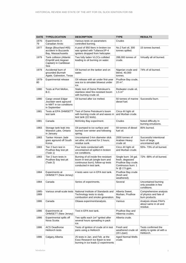
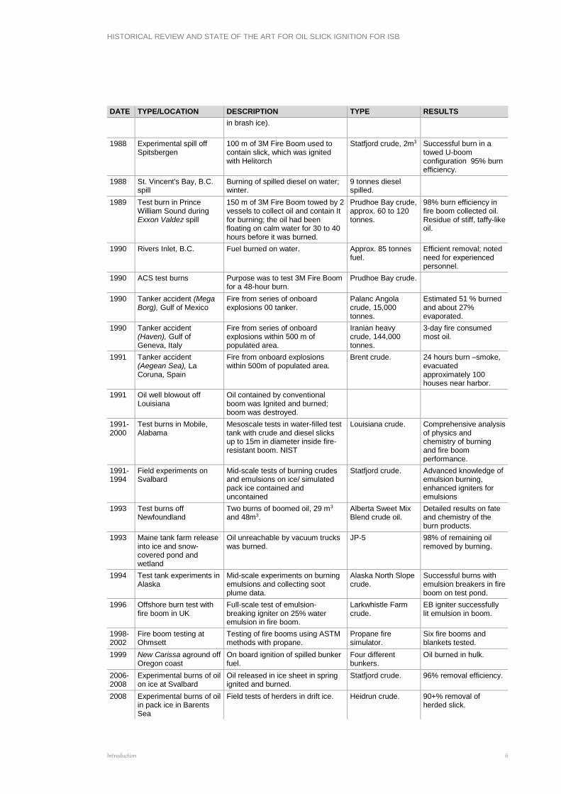
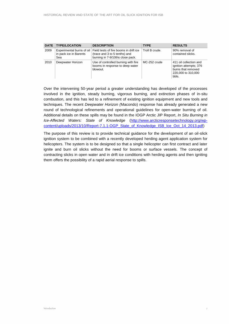
both sides of the Atlantic on the subject of oil slick ignition. Table 1 lists the 60 or so spills (both
accidental and experimental) that have provided a basis for the present knowledge of oil spill in-
situ burning in ice-affected waters. The most detailed information has been derived from
laboratory tests and the mesoscale tests noted.
Table 1. SUMMARY OF IN-SITU BURNING: TESTS AND USE ON SPILLS ON WATER AND IN
ICE-AFFECTED WATERS
DATE TYPE/LOCATION DESCRIPTION TYPE RESULTS
1958 Pipeline spill in Mackenzie River
Spill was boomed with logs and burned.
Crude Burn was successful
1967 Tanker accident (Torrey Canyon)
Attempts were made to burn oil on water with bombs, napalm and other materials.
100,000 tonnes of crude
40,000 to 50,000 tonnes of oil burned on ship.
1969 Holland Series of experiments. Igniter Kontax tested.
Crude Proved the possibility of burning slicks.
1969 Cargo ship Eiva sank releasing oil in Gulf of Finland
0il burned on shores and bays using paraffinic oil as primer.
15 tonnes of diesel fuel.
Burn was reported to be successful.
1969 Tanker Raphael went aground off Finland
Peat moss, fuel oil and petrol used. 60 tonnes of crude. 90% of oil was burned.
1970 Accident in Deception Bay, Quebec
Tank farm accident caused by slush avalanche. Onshore spill reached intertidal ice.
1500 tonnes of diesel and gasoline spilled.
Oil pumped to Ice surface and burned; some oil on ice, and contained by near shore ice also burned
1970 Accident in Chedabucto Bay (.Arrow)
Some isolated slicks were burned using Seabeads. Varsol also used as primer. Oil on shoreline was ignited and burned with napalm and a flame thrower.
Bunker C, approx. 16,000 tonnes.
Mixed results.
1970 Vessel collision in Tralhavet Bay, Sweden, March (Othello and Katelysia)
Spill was trapped in pack ice and a silica wicking agent (Cab- O-Sil ST-2-0) was used to burn. Conditions precluded mechanical containment and recovery.
Between 52,000 and 90,000 tonnes of Bunker C spilled.
Good results reported.
1972 Diesel fuel spill in ice-choked river in Sweden
Sorbent product Saneringsull used as wicking agent.
600 tonnes of diesel fuel oil.
400 tonnes burned.
1973 Canada Rimouski experiment Crude Demonstrated high removal rates possible, >75%.
1974-75
Experimental spill, Balaena Bay, Canadian Beaufort Sea
Oil spilled under ice was burned in spring as It accumulated in melt pools on the ice surface.
45 tonnes of crude. Highly successful burns; proved the effective use of burning oil in ice.
1976 Tanker Urquiola went aground off Spain
Oil burned accidentally over 3-day period.
100,000 tonnes of light Arabian crude.
1976 Accident In Lake Huron (Imperial St. Clair)
Oil became incorporated In ice, and numerous burns conducted as oil melted out of ice. Oily rags used as igniters.
Diesel and gasoline, 220 tonnes spilled.
80-95% of the oil burned.
1976 Tanker Argo Merchant went aground off Nantucket
Tullanox 500, primed with JP-4, used as igniter.
28,000 tonnes of No. 6 Fuel.
Not able to burn slicks on open water.
HISTORICAL REVIEW AND STATE OF THE ART FOR OIL SLICK IGNITION FOR ISB
Introduction 5
DATE TYPE/LOCATION DESCRIPTION TYPE RESULTS
1976-79
Experiments in Canadian Arctic
Various tests on parameters controlled burning.
Crudes
1977 Barge (Bouchard #65) accident In Buzzards Bay, Massachusetts
A pool of 950 liters in broken ice was ignited with Tullanox/JP-4 igniters dropped from helicopter.
No.2 fuel oil, 300 tonnes spilled.
15 tonnes burned.
1979 Tank collision (Atlantic Empr68 and Aegean Captain) in Caribbean Sea
Two fully laden VLCCs collided leading to oil burning on water.
288,000 tonnes of crude.
Virtually all oil burned.
1979 Accidental burn of grounded Burmah Agate, Galveston, Texas
Oil burned on the tanker and on water.
Nigerian crude and blend, 40,000 tonnes.
74% of oil burned.
1979-80
Experimental release Oil release with air under first-year sea ice to simulate blowout under ice.
Prudhoe Bay crude, 20 m3.
1980 Tests at Port Mellon, B.C.
Static test of Dome Petroleum's stainless steel fire-resistant boom with burning crude oil.
Redwater crude oil, 1.5 m3.
1980 Cargo vessel Edgar Jourdain went aground In NWT in ice conditions in September
Oil burned after ice melted. 50 tonnes of marine diesel fuel.
Successful burn.
1981 Tests at EPA OHMSETT test tank
Test of Dome Petroleum's boom with burning crude oil and waves in test tank (22 tests).
Circa 4X light oil and Murban crude.
1981 Canada McKinley Bay experiment. Crudes Noted difficulty In burning emulsions.
1983 Storage tank leak into Warwick Lake, Ontario in January
Oil pumped to ice surface and burned over winter and following spring.
59 tonnes of diesel fuel oil.
85% burned.
1983 Tanker Honam Jade goes aground off South Korea
Uncontained 3-km diameter slick set afire; oil burned for 2 hours; residue sunk.
2000 tonnes of Arabian Heavy crude oil.
Successful intentional burn of large, uncontained spill.
1983 Tier 2 burn test in Prudhoe Bay test pit (Task 1)
Four tests conducted with uncontained oil spilled in broken ice conditions.
Circo 4X light oil and Murban crude.
55%- 73% of oil burned.
1983 Tier 2 burn tests in Prudhoe Bay test pit (Task 2)
Burning of oil inside fire-resistant boom in test pit (single burn and continuous burn); follow-up tests conducted in test tank.
Single burn: 34 gal. fresh, degassed Prudhoe Bay crude. Continuous burn: 1 hr @ 2.5 gpm.
72% -88% of oil burned.
1984 Experiments at OHMSETT (New Jersey)
4 tests were run in EPA test tank. Prudhoe Bay crude (fresh and weathered).
1984 Canada Series of experiments. Several Uncontained burning only possible in few conditions.
1985-1989
Various small-scale tests National Institute of Standards and Technology tests to study combustion and smoke generation.
Alberta Sweet, Murban, Prudhoe Bay
Comprehensive analysis of physics and fate of burn products.
1986 Canada Ottawa experiment/analysis. Various Analysis shows PAH's about same in oil and residue.
1986 Experiments at OHMSETT (New Jersey)
Test in EPA test tank. Prudhoe Bay and Hibernia crudes.
1986 Experimental spills off Nova Scotia
Two spills each 1m3 ignited after several hours spreading in pack ice.
Alberta crude.
1986 ACS Deadhorse Helitorch tests
Tests of ignition of crude oil in test pans using a Helitorch
Fresh and weathered crude oil (20 L/pan)
Tests confirmed the ability to ignite oil with a Helitorch.
1986 Calgary,Alberta 25 tests in Jan. and Feb. at the Esso Research Ice Basin to test burning in ice leads (2 experiments
Aged Normal Wells crude.
HISTORICAL REVIEW AND STATE OF THE ART FOR OIL SLICK IGNITION FOR ISB
Introduction 6
DATE TYPE/LOCATION DESCRIPTION TYPE RESULTS
in brash ice).
1988 Experimental spill off Spitsbergen
100 m of 3M Fire Boom used to contain slick, which was ignited with Helitorch
Statfjord crude, 2m3 Successful burn in a towed U-boom configuration 95% burn efficiency.
1988 St. Vincent's Bay, B.C. spill
Burning of spilled diesel on water; winter.
9 tonnes diesel spilled.
1989 Test burn in Prince William Sound during Exxon Valdez spill
150 m of 3M Fire Boom towed by 2 vessels to collect oil and contain It for burning; the oil had been floating on calm water for 30 to 40 hours before it was burned.
Prudhoe Bay crude, approx. 60 to 120 tonnes.
98% burn efficiency in fire boom collected oil. Residue of stiff, taffy-like oil.
1990 Rivers Inlet, B.C. Fuel burned on water. Approx. 85 tonnes fuel.
Efficient removal; noted need for experienced personnel.
1990 ACS test burns Purpose was to test 3M Fire Boom for a 48-hour burn.
Prudhoe Bay crude.
1990 Tanker accident (Mega Borg), Gulf of Mexico
Fire from series of onboard explosions 00 tanker.
Palanc Angola crude, 15,000 tonnes.
Estimated 51 % burned and about 27% evaporated.
1990 Tanker accident (Haven), Gulf of Geneva, Italy
Fire from series of onboard explosions within 500 m of populated area.
Iranian heavy crude, 144,000 tonnes.
3-day fire consumed most oil.
1991 Tanker accident (Aegean Sea), La Coruna, Spain
Fire from onboard explosions within 500m of populated area.
Brent crude. 24 hours burn –smoke, evacuated approximately 100 houses near harbor.
1991 Oil well blowout off Louisiana
Oil contained by conventional boom was Ignited and burned; boom was destroyed.
1991-2000
Test burns in Mobile, Alabama
Mesoscale tests in water-filled test tank with crude and diesel slicks up to 15m in diameter inside fire-resistant boom. NIST
Louisiana crude. Comprehensive analysis of physics and chemistry of burning and fire boom performance.
1991-1994
Field experiments on Svalbard
Mid-scale tests of burning crudes and emulsions on ice/ simulated pack ice contained and uncontained
Statfjord crude. Advanced knowledge of emulsion burning, enhanced igniters for emulsions
1993 Test burns off Newfoundland
Two burns of boomed oil, 29 m3 and 48m3.
Alberta Sweet Mix Blend crude oil.
Detailed results on fate and chemistry of the burn products.
1993 Maine tank farm release into ice and snow-covered pond and wetland
Oil unreachable by vacuum trucks was burned.
JP-5 98% of remaining oil removed by burning.
1994 Test tank experiments in Alaska
Mid-scale experiments on burning emulsions and collecting soot plume data.
Alaska North Slope crude.
Successful burns with emulsion breakers in fire boom on test pond.
1996 Offshore burn test with fire boom in UK
Full-scale test of emulsion-breaking igniter on 25% water emulsion in fire boom.
Larkwhistle Farm crude.
EB igniter successfully lit emulsion in boom.
1998-2002
Fire boom testing at Ohmsett
Testing of fire booms using ASTM methods with propane.
Propane fire simulator.
Six fire booms and blankets tested.
1999 New Carissa aground off Oregon coast
On board ignition of spilled bunker fuel.
Four different bunkers.
Oil burned in hulk.
2006- 2008
Experimental burns of oil on ice at Svalbard
Oil released in ice sheet in spring ignited and burned.
Statfjord crude. 96% removal efficiency.
2008 Experimental burns of oil in pack ice in Barents Sea
Field tests of herders in drift ice. Heidrun crude. 90+% removal of herded slick.
HISTORICAL REVIEW AND STATE OF THE ART FOR OIL SLICK IGNITION FOR ISB
Introduction 7
DATE TYPE/LOCATION DESCRIPTION TYPE RESULTS
2009 Experimental burns of oil in pack ice in Barents Sea
Field tests of fire booms in drift ice (trace and 3 to 5 tenths) and burning in 7-9/10ths close pack.
Troll B crude. 90% removal of contained slicks.
2010 Deepwater Horizon Use of controlled burning with fire booms in response to deep water blowout.
MC-252 crude 411 oil collection and ignition attempts; 376 burns that removed 220,000 to 310,000 bbls.
Over the intervening 50-year period a greater understanding has developed of the processes
involved in the ignition, steady burning, vigorous burning, and extinction phases of in-situ
combustion, and this has led to a refinement of existing ignition equipment and new tools and
techniques. The recent Deepwater Horizon (Macondo) response has already generated a new
round of technological refinements and operational guidelines for open-water burning of oil.
Additional details on these spills may be found in the IOGP Arctic JIP Report, In Situ Burning in
Ice-Affected Waters: State of Knowledge (http://www.arcticresponsetechnology.org/wp-
content/uploads/2013/10/Report-7.1.1-OGP_State_of_Knowledge_ISB_Ice_Oct_14_2013.pdf)
The purpose of this review is to provide technical guidance for the development of an oil-slick
ignition system to be combined with a recently developed herding agent application system for
helicopters. The system is to be designed so that a single helicopter can first contract and later
ignite and burn oil slicks without the need for booms or surface vessels. The concept of
contracting slicks in open water and in drift ice conditions with herding agents and then igniting
them offers the possibility of a rapid aerial response to spills.
HISTORICAL REVIEW AND STATE OF THE ART FOR OIL SLICK IGNITION FOR ISB
Oil Slick Ignition 8
CHAPTER 1. OIL SLICK IGNITION
Ignition involves two components: heating the floating slick to a temperature high enough such
that the liquid hydrocarbons are vaporizing quickly enough to generate a concentration in the air
layer above the slick that will support burning (the Lower Flammability Limit or Lean Flammability
Limit), and then providing ignition energy to initiate burning. The temperature at which a slick
produces vapours at a sufficient rate to catch fire is called the Flash Point. At a temperature called
the Fire Point, which is a few degrees above the Flash Point, the oil is warm enough to supply
vapours at a rate sufficient to support continuous burning (Kanury 1988).
An important objective of in-situ burning of oil is to ignite the maximum possible area of the slick.
Ignition of an oil slick and subsequent flame spreading are strong functions of the temperature of
the slick, its volatility, its degree of emulsification, and the location of the ignition on the slick
relative to the wind. If oil is at a temperature above its Flash Point, ignition is simple and flame
propagation is normally rapid; otherwise, ignition and flame spreading can be slow and difficult.
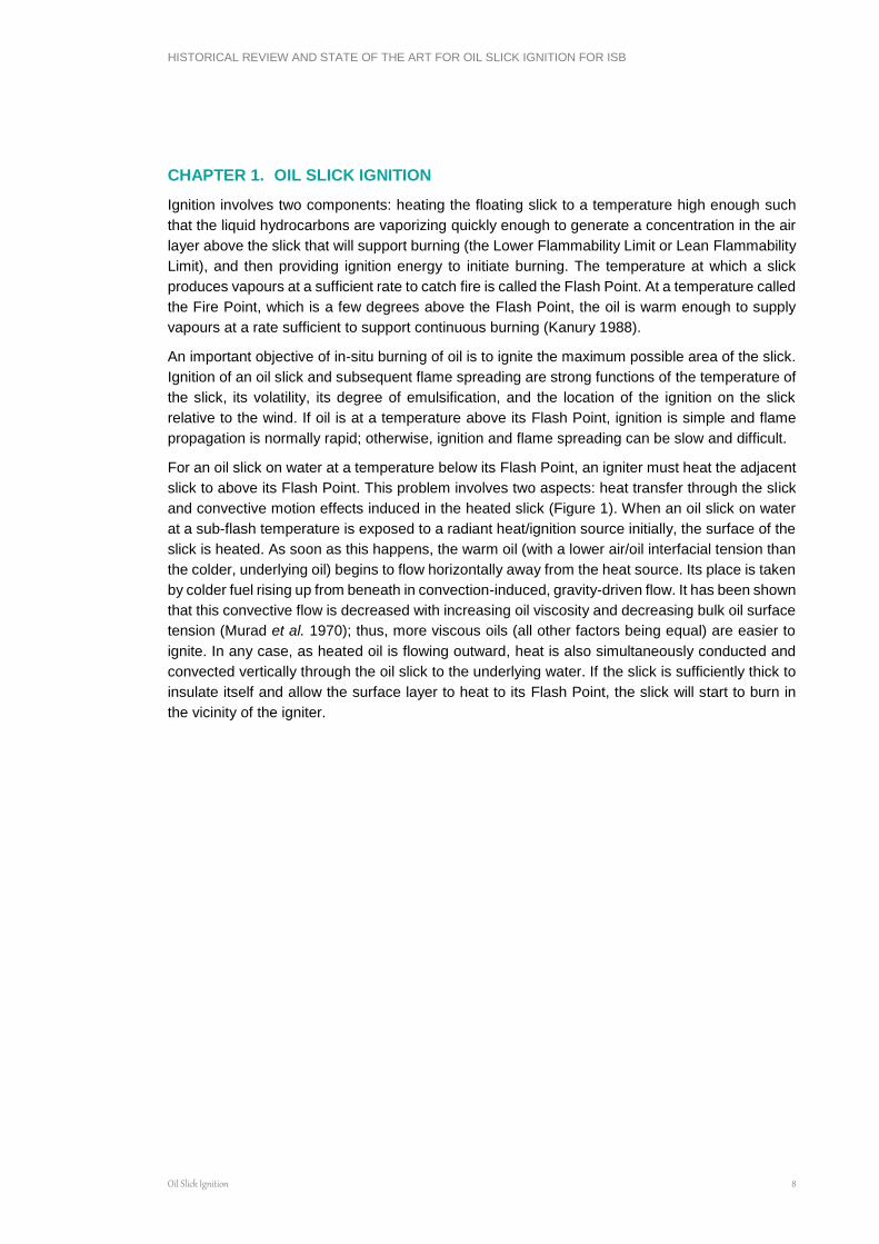
For an oil slick on water at a temperature below its Flash Point, an igniter must heat the adjacent
slick to above its Flash Point. This problem involves two aspects: heat transfer through the slick
and convective motion effects induced in the heated slick (Figure 1). When an oil slick on water
at a sub-flash temperature is exposed to a radiant heat/ignition source initially, the surface of the
slick is heated. As soon as this happens, the warm oil (with a lower air/oil interfacial tension than
the colder, underlying oil) begins to flow horizontally away from the heat source. Its place is taken
by colder fuel rising up from beneath in convection-induced, gravity-driven flow. It has been shown
that this convective flow is decreased with increasing oil viscosity and decreasing bulk oil surface
tension (Murad et al. 1970); thus, more viscous oils (all other factors being equal) are easier to
ignite. In any case, as heated oil is flowing outward, heat is also simultaneously conducted and
convected vertically through the oil slick to the underlying water. If the slick is sufficiently thick to
insulate itself and allow the surface layer to heat to its Flash Point, the slick will start to burn in
the vicinity of the igniter.
HISTORICAL REVIEW AND STATE OF THE ART FOR OIL SLICK IGNITION FOR ISB
Oil Slick Ignition 9
Figure 1 Heat transfer and convective motion during slick ignition
(source: Marine Spill Response Corporation)

HISTORICAL REVIEW AND STATE OF THE ART FOR OIL SLICK IGNITION FOR ISB
Oil Slick Ignition 10
Extensive experimentation with a variety of oil types, igniters and environmental conditions
(Maybourn 1971, Energetex 1978 and 1980, Allen 1987, S.L. Ross 1989, Bech et al. 1993) has
confirmed the following "rules-of-thumb" for the ignition of oils on water in relatively calm,
quiescent conditions:
Note that although thick residual fuel oil slicks have been found to be ignitable, it is likely that
efficient burning of a large spill of residual oil in-situ will be extremely difficult unless promoters
like diesel are first spread on its surface to enhance flame spreading.
The maximum ignitable water content of an emulsion seems to be controlled by three factors:
degree of weathering of the parent oil (more evaporated emulsions are more difficult to ignite);
stability of the emulsion at temperatures less than 100°C (Cabioc'h 1993 postulates that high
asphaltene emulsions are more difficult to ignite); and,
strength of the igniter.
The maximum ignitable water content for oils has ranged from 10% to 70% (Energetex 1980, SL
Ross 1989, Bech et al. 1992, Cabioc'h 1993, Guenette et al. 1994, SL Ross 1997, Fritt-
Rasmussen et al. 2011). Guenette et al. (1994) showed that emulsions with water contents as
high as 50%, when herded into a contained oil slick fire by current and wind action, would ignite
and burn efficiently. This was also observed during burn operations at the Macondo response
(Mabile 2010).
Not only are water-in-oil emulsions difficult to ignite, flame spreading over their surface is much
slower. Energetex (1980 and 1981), Hossain and Mackay (1981), Smith and Diaz (1987), SL
Ross (1989), Allen (1991), Bech et al. (1992) Guenette et al. (1994) and SL Ross (1995 and 1997)
and Wu et al. (1997) have all noted significant reductions in flame spreading rates with increasing
water content. This is likely due to a combination of the following factors:
increased slick viscosity, slowing interfacial-tension-induced flow and flame spreading;
increased heat transfer by conduction through the emulsified slick;
increased Flash/Fire Points of the emulsified slick; and
delays due to the need to break the emulsion and form a layer of water-free oil for the flame
to propagate across.
Aside from oil type and thickness, other factors can affect the ignitability of oil slicks as well. The
key parameters are:
wind speed; and
Ignition Rules of Thumb
The minimum ignitable thickness for fresh crude oil on water is about 1mm;
• The minimum ignitable thickness for aged, unemulsified crude oil and diesel fuels is about 2 to
5mm;
• The minimum ignitable thickness for residual fuel oils, such as IFO 380 (aka Bunker “C” or No.
6 fuel oil) is about 10mm; and,
• Once 1 m2 of burning slick has been established, the fire can sustain itself without an external
heat source.
Emulsion slicks having stable water contents of 25% or more are generally unignitable. Some crudes form meso-stable emulsions that can be ignited at much higher water contents. Paraffinic crudes appear to fall into this category.

HISTORICAL REVIEW AND STATE OF THE ART FOR OIL SLICK IGNITION FOR ISB
Oil Slick Ignition 11
igniter strength.
Secondary factors include:
ambient temperatures; and
waves.
The effects of wind speed on the ignitability of oil slicks have been studied both theoretically and
experimentally. Murad et al. (1970) developed a mathematical model showing how the wind
decreases the volume of ignitable vapours above the slick. Wind speed also reduces the
ignitability of oil slicks at sub-flash temperatures possibly by increasing convective heat and mass
transfer at the oil/air interface.
In tests with solid propellant igniters, Energetex (1981) reported that, in an 8 m/s wind created by
a fan adjacent to the slick (equivalent to an 11 m/s wind measured at a 10 m elevation) ignition
of weathered crude and marine diesel slicks was not possible, even with slick thicknesses of 10
mm. For fresh crude oil a 2 mm slick was ignitable in a 3 m/s wind but not in an 8 m/s wind
(equivalent to 11 m/s @ 10 m): the minimum ignitable thickness for fresh crude in an 8 m/s (11
m/s @ 10 m) wind was 5 mm. Allen (1987) reports that winds of 3 to 5 m/s did not affect slick
ignition with small (60 to 120 mL) blobs of gelled gasoline; but, winds of 8 m/s required the use of
250 to 500 mL blobs to effect ignition. The maximum wind speed for successful ignition for large
burns has been estimated as 10 to 12 m/s (Bech et al. 1993, Cabioc'h 1993).
Wave action can prevent ignition of marginally ignitable slicks (Tam and Purves 1980, Energetex
1981, Bech et at. 1993). Energetex (1981) reports that the minimum ignitable thickness for one
week aged Prudhoe Bay crude increased from about 3 mm in a 5 m/s wind to 10 mm with the
application of 10 cm high waves. This is believed to be due to forced convection heat transfer
induced by the waves making it more difficult for the igniter to heat the surface of the oil slick to
its Flash Point.
Ambient temperature can also affect slick ignitability. If an oil slick is at a temperature above its
Flash Point it will ignite rapidly and easily; however, oil slicks at sub-flash temperatures are more
difficult to ignite. Ambient temperature has a greater effect on flame spreading velocity than on
ignition, as discussed in the next section.
1.1 Flame Spreading
Flame spread is a crucial aspect of effective in-situ burning; if the fire does not spread to cover a
large part of a slick, overall removal efficiency will be low. Flame spreading can be divided into
two distinct categories: sub-flash spreading and super-flash spreading with an intervening
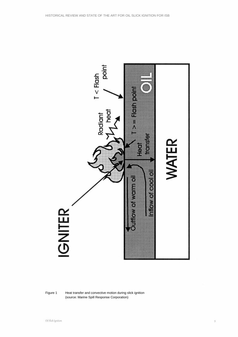
transition zone characterised by pulsating spread. The dependence of flame spreading velocity
on liquid temperature is shown in Figure 2 (Akita 1972) for methanol. At temperatures above the
fluid's Flash Point, flame spreading is controlled by vapour phase effects. As the temperature
rises from the Flash Point to the stoichiometric temperature (the liquid temperature required to
produce vapour at a rate allowing combustion of stoichiometric amounts of fuel and oxygen) the
flame spreading velocity increases from the laminar flame burning velocity at the lean flammability
limit to a maximum that is on the order of the laminar flame burning velocity for a stoichiometric
mixture of fuel vapour and air. For sub-flash fuel temperatures, the flame spreading velocity
seems to be controlled by liquid- phase heat and mass transfer phenomena.
HISTORICAL REVIEW AND STATE OF THE ART FOR OIL SLICK IGNITION FOR ISB
Oil Slick Ignition 12
Figure 2 Relationship between the liquid temperature and the rate of plane flame spread of methanol in a vessel
2.6 cm wide and 1.0 cm deep. (source: Marine Spill Response Corporation)
Starting at a temperature well below the Flash Point (say -20°C on Figure 2) the flame spreading
is controlled by the rate at which cold fuel in front of the flame is warmed by the advancing flame
front. There are two mechanisms by which heat is conducted from the flame to the cold fuel:
radiation and convective flow (Glassman et al. 1968, Sirignano and Glassman 1970, Mackinven
et al. 1970, Akita 1972). In the early stages of fire spreading over a sub-flash fuel on water, it is
the convective flow process that dominates; for larger fires, the radiation of heat dominates
HISTORICAL REVIEW AND STATE OF THE ART FOR OIL SLICK IGNITION FOR ISB
Oil Slick Ignition 13
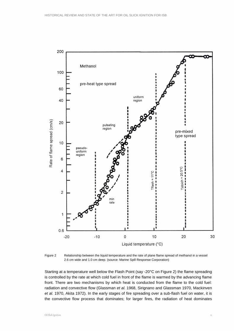
(Mackinven et al. 1970). Figure 3 shows a schematic cross-section of an advancing flame that
illustrates the processes involved for a quiescent sub-flash situation.
Figure 3 Schematic representation of the spreading flame (source: Marine Spill Response Corporation)
For small fires, and in the early stages of a larger fire, fuel underneath the leading edge of the
flame front is hotter than the unignited fuel; as such, the hot fuel has a lower interfacial tension
than the cold fuel and tends to flow forward over it (Mackinven et al. 1970, Glassman et al. 1968,
Torrance and Mahajan et al. 1974). This is called the Marangoni effect. This interfacial tension
flow outwards sets up a return flow of cold oil beneath the warm layer. Additionally the combustion
process itself sets up a bulk inward flow towards the fuel (Torrance and Mahajan 1974). Further
resistance to the interfacial flow is provided by viscous dissipation in the warm fuel layer itself
(Glassman and Hansel 1968, Glassman et al. 1969). Figure 4 shows the dependence of flame
velocity on fuel viscosity for a slick of kerosene at temperatures 40°C below its Flash Point
(Glassman et al. 1969). It is interesting to note that the flow-dissipating effects of increased
viscosity aid in ignition of oil, but detract from subsequent flame spreading.
As the bulk temperature of the warming fuel approaches the Flash Point on Figure 3, the flame
begins to pulsate. This pulsating region is characterised by a thin, blue ''pre-mixed'' flame
travelling ahead of the yellow "diffusion" flame front. Akita (1972), Glassman and Hansel (1968),
and Mackinven et al. (1970) state that for hydrocarbon fuels this pulsating flame relates to the
difference between the Flash and Fire Points of the fuel.
HISTORICAL REVIEW AND STATE OF THE ART FOR OIL SLICK IGNITION FOR ISB
Oil Slick Ignition 14
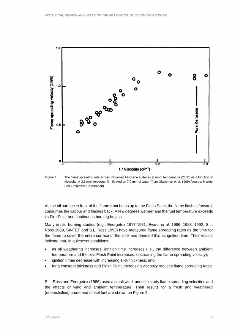
Figure 4 The flame spreading rate across thickened kerosene surfaces at room temperature (21°C) as a function of
viscosity. A 3.5 mm kerosene film floated on 7.0 mm of water (from Glassman et al. 1969) (source: Marine
Spill Response Corporation)
As the oil surface in front of the flame front heats up to the Flash Point, the flame flashes forward,
consumes the vapour and flashes back. A few degrees warmer and the fuel temperature exceeds
its Fire Point and continuous burning begins.
Many in-situ burning studies (e.g., Energetex 1977-1981, Evans et al. 1986, 1988, 1992, S.L.
Ross 1989, SINTEF and S.L. Ross 1993) have measured flame spreading rates as the time for
the flame to cover the entire surface of the slick and denoted this as ignition time. Their results
indicate that, in quiescent conditions:
as oil weathering increases, ignition time increases (i.e., the difference between ambient
temperature and the oil's Flash Point increases, decreasing the flame spreading velocity);
ignition times decrease with increasing slick thickness; and,
for a constant thickness and Flash Point, increasing viscosity reduces flame spreading rates.
S.L. Ross and Energetex (1986) used a small wind tunnel to study flame spreading velocities and
the effects of wind and ambient temperature. Their results for a fresh and weathered
(unemulsified) crude and diesel fuel are shown on Figure 5.
HISTORICAL REVIEW AND STATE OF THE ART FOR OIL SLICK IGNITION FOR ISB
Oil Slick Ignition 15
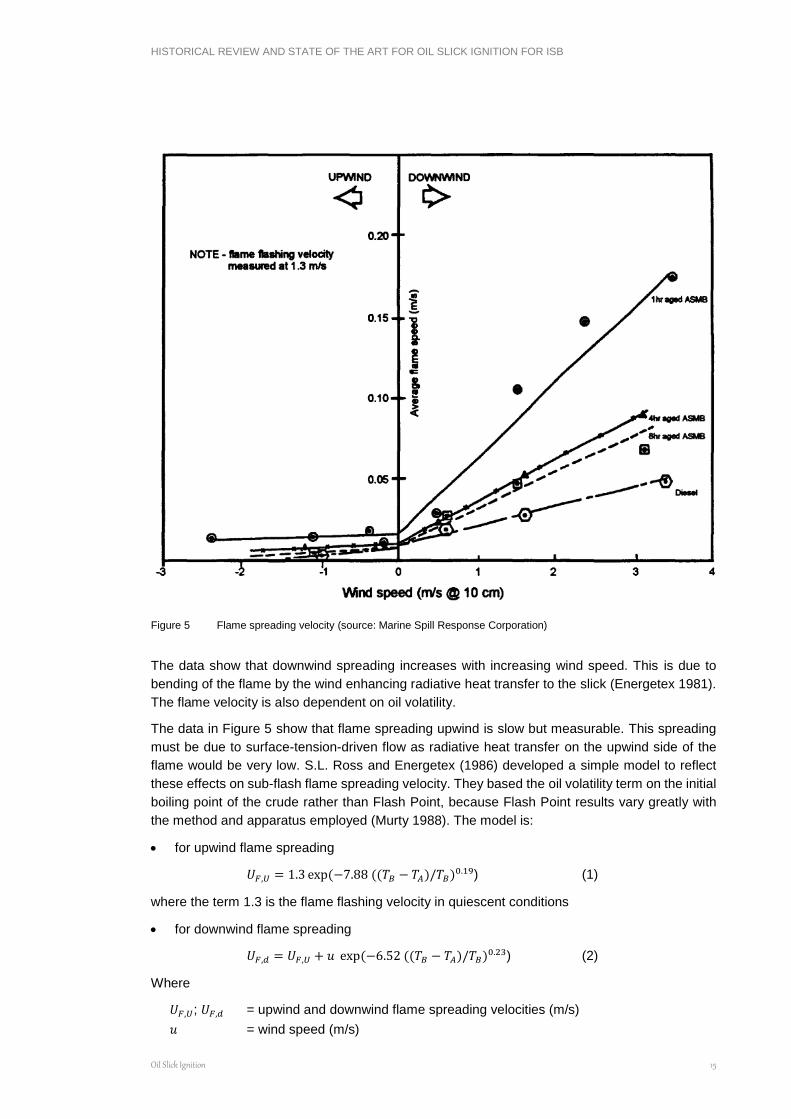
Figure 5 Flame spreading velocity (source: Marine Spill Response Corporation)
The data show that downwind spreading increases with increasing wind speed. This is due to
bending of the flame by the wind enhancing radiative heat transfer to the slick (Energetex 1981).
The flame velocity is also dependent on oil volatility.
The data in Figure 5 show that flame spreading upwind is slow but measurable. This spreading
must be due to surface-tension-driven flow as radiative heat transfer on the upwind side of the
flame would be very low. S.L. Ross and Energetex (1986) developed a simple model to reflect
these effects on sub-flash flame spreading velocity. They based the oil volatility term on the initial
boiling point of the crude rather than Flash Point, because Flash Point results vary greatly with
the method and apparatus employed (Murty 1988). The model is:
for upwind flame spreading
𝑈𝐹,𝑈 = 1.3 exp(−7.88 ((𝑇𝐵 − 𝑇𝐴)/𝑇𝐵)0.19) (1)
where the term 1.3 is the flame flashing velocity in quiescent conditions
for downwind flame spreading
𝑈𝐹,𝑑 = 𝑈𝐹,𝑈 + 𝑢 exp(−6.52 ((𝑇𝐵 − 𝑇𝐴)/𝑇𝐵)0.23) (2)
Where
𝑈𝐹,𝑈; 𝑈𝐹,𝑑 = upwind and downwind flame spreading velocities (m/s)
𝑢 = wind speed (m/s)

HISTORICAL REVIEW AND STATE OF THE ART FOR OIL SLICK IGNITION FOR ISB
Oil Slick Ignition 16
𝑇𝐵 = initial boiling point of the oil (as measured by ASTM D87 distillation) [°K]
𝑇𝐴 = temperature of oil slick [°K]
Data from Smith and Diaz (1987) indicate an upwind flame spreading velocity of 0.04 m/s for fresh
Prudhoe Bay crude and 0.025 m/s for weathered crude against 4 to 7 m/s winds. For crosswind
flame spreading the upwind flame velocity is used. This is consistent with the observation that, in
windy conditions, flames spread nearly straight downwind from an ignition point without much
crosswind spread (e.g., Energetex 1981, Dome 1981). If a slick has a large cross-wind dimension,
it is necessary to ignite it at multiple points perpendicular to the wind across its upwind edge in
order to achieve effective burning. Data reported in Bech et al. 1992 for downwind flame
spreading velocities over slicks of weathered crude oil also show a trend in declining flame
spreading velocity with increased weathering. Energetex (1981) concluded that flame spreading
over emulsions is more sensitive to wind influences than unemulsified oils. Bech et al. (1993) and
Guenette et al. (1994) gave the maximum wind speed for burning emulsions as 36 km/h (20
knots). SL Ross (1995) confirmed this.
It has been observed numerous times in the field that, although flame spreads slowly upwind or
crosswind, the presence of a barrier or edge that provides a wind break can permit rapid upwind
or cross-wind spreading.
Currents and regular waves (or swell) do not seem to affect flame spreading for unemulsified oils,
but choppy or steep waves have been noted to curtail flame spreading (Energetex 1981, Dome
Petroleum 1981a, Bech et al. 1993). Bech et al. (1993) have noted that flame spreading over
emulsions is very sensitive to wave action; even regular, swell-type waves prevented ignition and
flame spreading over heavily weathered, 25% water emulsions.

HISTORICAL REVIEW AND STATE OF THE ART FOR OIL SLICK IGNITION FOR ISB
Igniters 17
CHAPTER 2. IGNITERS
This section starts with a brief chronological history of the development of igniters. This is followed
by a review of igniters that have been researched or developed but are no longer available. These
discussions are followed by a more detailed presentation of commercially available igniter
systems and some that are currently being considered for further test and evaluation.
2.1 Brief History of Igniter Development
Many different ignition devices have been used over the years to ignite or attempt to ignite marine
oil spills. In 1967 four attempts were made to ignite seemingly thick oil slicks on the sea near the
Torrey Canyon using pyrotechnic devices containing sodium chlorate, but these attempts were
unsuccessful (Swift et al. 1968; Anonymous 1967). It was concluded that even though the spilled
oil (Kuwait crude) had been on the water surface for only 40 minutes, it had emulsified to such an
extent that it would not ignite.
Oil on the shore from the Torrey Canyon spill also proved virtually impossible to ignite and burn.
Some success was reported in burning unemulsified oil in pools between rocks (Swift et al. 1968)
using flame throwers to ignite pools. Emulsified oil could be burned on the beach as long as flame
was applied directly to the oil. Once the flame was removed the combustion stopped.
Kontax was an igniter developed at the time by Edward Michels GmbH of Essen, Germany. It
was demonstrated on a test spill off Holland where it successfully ignited and burned 10 tonnes
of heavy Arabian crude (Freiberger and Byers 1971, Energetex 1978). The potential of Kontax
was also demonstrated at the Arrow spill in 1970 where some of the spilled oil was primed with
two drums of fresh oil and ignited with a Kontax igniter (Coupal 1972).
Another igniter - Oilex Fire, produced by Keltron Inc. of Switzerland - consisted of a sorbent (Oilex)
plus a hydro-igniting agent. The company reported the chemical's use on small spills in Swiss
lakes and in the Adriatic Sea (Freiberger and Byers 1971).
On December 27, 1976, the Argo Merchant went aground near Nantucket Island and spilled most
of its cargo of 28,000 tonnes of No. 6 fuel oil. Part of the response by the U.S. Coast Guard
involved attempts to burn the oil. One 30 m x 40 m x 15 cm thick slick was treated with Tullanox
500 (a wicking/insulating agent), primed with 200 L of JP-4 and ignited with JP-4-soaked cotton
sheets set afire with a flare. About 95% of the Tullanox was blown off the treated slick by wind
and the flames would not spread from the sheet to the primed slick. In another experiment, boxes
of Tullanox 500 soaked with JP-4 fuel were dropped onto a slick from a helicopter and ignited
with timed thermite grenades. The isolated boxes burned but the flames did not spread (Det
norske Veritas 1979, Battelle 1979).
On January 28, 1977, some 300,000 L of No. 2 fuel oil was spilled onto ice-covered waters in
Buzzards Bay, Massachusetts from the barge Bouchard #65. Boxes of Tullanox soaked with jet
fuel were dropped from helicopters onto pools of oil in the broken ice with delay-fuses. Thermite
grenades were used to ignite the boxes. The ensuing fires burned for 1-1/2 to 2 hours and
consumed 4000 to 8000 L of oil. The 38 to 46 km/h (20 to 25 knot) winds drove the flames from
pool to pool in areas nearby while in other areas the fires did not spread. Another series of burns
was conducted at a later date, ignited with knotted rags soaked in diesel fuel (Schrier and Ediam
1979, Ruby et al. 1978).
Starting in 1977, considerable effort was devoted to developing an aerial ignition capability in
support of potential spills from offshore exploration activities in the Beaufort Sea. Energetex
HISTORICAL REVIEW AND STATE OF THE ART FOR OIL SLICK IGNITION FOR ISB
Igniters 18
Engineering evaluated and tested five devices (Kontax, Kontax with gasoline, solid propellant,
solid fuel, and gasoline with sodium). Solid fuel and solid propellant igniters with a fuse wire were
ranked highest (Energetex 1978). Subsequently, two igniters were developed in Canada: the
Dome igniter (Buist et al. 1981; Energetex 1982a and b) and the EPS igniter (Meikle 1981a and
b, Twardawa and Couture 1983).
Laser-based ignition systems received considerable attention in the 1970s and 80s (Waterworth
1987, Whittaker 1987, Frish et al. 1989, Laisk 1976). A land-based system proved capable of
igniting oil slicks on water and was demonstrated (Frish et al. 1989). The various components of
a helicopter-borne system were researched under contract to Environment Canada and the
Minerals Management Service (now the Bureau of Safety and Environmental Enforcement);
however, further development of the prototype system awaits private sector involvement and
possible commercialisation. High capital cost, energy requirements and platform stabilisation
requirements to compensate for helicopter vibration and motion to permit steady focusing of the
laser beam on targets (to preheat the oil) were believed to be a few of the reasons for not
proceeding at the time.
In Alaska, a forest-fire fighting tool known as the Helitorch was discovered in the mid-1980s to be
an effective aerial ignition system for oil spills (Allen 1986). Considerable testing and refinement
of the device (Allen 1987) has resulted in the Helitorch being stockpiled around the world as the
igniter-of-choice for in-situ burning.
Research efforts in the mid-1990s looked at extending the capabilities of ignition systems to deal
with water-in-oil emulsions (S.L. Ross 1989, Bech et al. 1992, SINTEF and S.L. Ross 1993). In
this work, emulsions with up to 40% water content were successfully burned, however, higher-
strength igniters using gelled crude oil, rather than the conventional use of gelled gasoline, were
required for successful ignition. Further work by Guenette and Sveum (1995) used various gelled
fuels (gasoline, diesel, and Bunker C), an emulsion breaker and an anti-foaming agent to
successfully ignite and burn emulsions with water contents of up to 50%. The work showed the
potential for the concept of a one-step break-and-burn process for igniting and burning emulsions.
During trials off Lowestoft, England in 1996 (Guenette and Thornborough 1997), the concept was
demonstrated using a Helitorch to deliver the emulsion breaker and fuel mixture to successfully
ignite and burn emulsions.
There has been little work done on aerial igniter development in the last two decades. The Heli-
torch is still stockpiled by some response organisations, and has been used in field trials such as
the NOBE experiment in 1993 (Fingas et al. 1994), the Lowestoft trials in 1996 (Thornborough
1997), two inland burns in Utah (Williams et al. 2003), and recent tests of aerial application of
herders near Fairbanks, Alaska (Potter et al. 2015). Other field trials and operational uses of in-
situ burning have used simple ad-hoc igniters. For example, during the response to the Macondo
blowout in 2010, in-situ burns were initiated using igniters assembled from off-the-shelf
components: a marine signal flare attached to a plastic bottle filled with gelled fuel (Mabile 2010).
The Heli-torch was not employed at the Macondo blowout because of the distance of the ISB
operations from shore.
Inland or marsh burns are commonly initiated using propane weed burners (May and Wolfe 1997,
Hess et al. 1997).
The US Navy Supervisor of Salvage (SUPSALV) undertook a programme to develop an igniter
that did not require a helicopter to deploy and that could be shipped safely by surface or air
transport (Moffatt and Hankins 1997). Through an iterative process involving experimentation with
HISTORICAL REVIEW AND STATE OF THE ART FOR OIL SLICK IGNITION FOR ISB
Igniters 19
different fuel compounds, a flare-type device was produced that could successfully ignite and
burn diesel fuel and 25% water content emulsions. This unit was never commercialised.
Recently, Elastec and Desmi-AFTI have developed commercially available handheld ignition
system based on the technology used for ad-hoc igniters in the Deepwater Horizon response.
2.2 Summary of Disused Ignition Systems
The following ignition systems had been used or were researched at one time but are no longer
available, recommended, or considered for use:
2.2.1 Kontax
The Kontax igniter was produced by Edward Michels GmbH of Essen, Germany. Production of
the device ceased in the mid-to late-1970s (Energetex 1978). The device consisted of a 4 cm
diameter cylindrical metal screen 30.5 cm long and capped at both ends. A metal bar coated with
metallic sodium ran through the centre of the cylinder. The annulus was filled with calcium carbide.
The device weighed 1.2 kg. For safety reasons the Kontax igniter was stored in a sealed plastic
bag.
The Kontax igniter had a unique feature: it did not require activation or a starter. When the device
was exposed to water the sodium metal reacted to produce heat and hydrogen, which instantly
ignited. At the same time the calcium carbide reacted with water to produce acetylene which was
subsequently ignited by the burning hydrogen. The flame from the burning acetylene preheated
and ignited oil vapours.
Tests to evaluate Kontax were conducted in 1969 by the Dutch government (Battelle 1979). The
tests were conducted 25 miles offshore and on beaches; the oils used were heavy and light
Arabian crude. One test involved a 9 tonne slick covering about 2000 m2 (0.5 cm thick) in a free-
floating lumber boom. The bags containing the Kontax were punctured and thrown into the slick.
The igniters were successful; flames of 15 to 20 m high were reported and 98 to 99% oil removal
efficiency was estimated. A Kontax-to-oil ratio of 1: 100 by weight was judged to be appropriate.
Tests with the Kontax igniter (Energetex 1978) showed that it produced a large flame area (3000
cm2) with a relatively low flame temperature (770° C). This combination produced a relatively high
flame emissivity of 2.25 kW/m2. Although Kontax proved effective in both field and tank trials as
a surface-deployed igniter (Freiberger and Byers 1971, Energetex 1978), the device proved less
effective when dropped from a height of 11.5 m, simulating deployment from a helicopter. The
ignition success rate declined from 100% in the surface tests to 60% in the aerial tests. The main
reason for the latter result was that the large splash caused by the Kontax igniter entering the
water drove the oil away; by the time the oil had returned, the igniter had generated a ring of
calcium hydroxide foam that kept the oil away.
Energetex (1978) tested a modification to the Kontax igniter, which involved combining a small
amount of gasoline with the device. This inclusion of gasoline was intended as a fuel to bridge
the calcium hydroxide foam barrier. This modification resulted in a slightly higher flame
temperature (790° C) and better aerial deployment ignition success (80%).

HISTORICAL REVIEW AND STATE OF THE ART FOR OIL SLICK IGNITION FOR ISB
Igniters 20
It is not clear why Kontax was taken out of production. It may have been due to a general lack of
interest in in-situ burning at the time, or due to the potential dangers and stringent requirements
for storing, transporting, and using the igniters.
2.2.2 Solid Propellants
Solid propellants, also known as solid rocket fuel, are composed of a solid mixture of various
portions of ammonium perchlorate oxidiser, metal fuel (magnesium or aluminum), and an organic
binder. They have been used in a variety of igniters. Solid propellant igniters, in various shapes
and utilizing various starters (electrical, chemical or fuses) have been extensively tested
(Energetex 1978). Such igniters exhibit very high flame temperatures (about 1230°C) and high
flame emissivities (1.75 kW/m2) but are consumed rapidly. They require mounting in a housing to
suspend them no more than 5 cm above the oil/air interface. In water surface tests, solid
propellant gave an 89% ignition success rate; and an 80% success rate in aerial-deployment tests
with a fuse-wire starter (all other starter mechanisms resulted in lower success rates).
Solid propellants were once considered but now are not recommended for use alone as an oil
spill igniter. Rather, they and solid fuels (discussed next) are used in conjunction with other
components in currently available igniter systems.
Examples of igniters that were developed using solid propellant include the Dome igniter (still
stockpiled by ACS in Alaska) and the EPS Igniter.
EPS Igniter
The Environmental Protection Service (EPS) Igniter was an air-deployable pyrotechnic device
developed by the Canadian Environmental Protection Service, a division of Environment Canada,
in cooperation with Canadian Department of National Defence Research Establishment,
Valcartier (DREV) and the Arctic Marine Oilspill Program (AMOP) (Twardawa and Couture 1983).
The igniter (Figure 6) is approximately 25 cm square and 13 cm high and weighs nearly 2 kg. The
unit consists of a pyrotechnic device sandwiched between two layers of foam flotation and is
activated by a self-contained firing mechanism. It is intended to be a hand-thrown device.
The EPS igniter was marketed in the past as the "PYROID" igniter manufactured by ABA
Chemical Ltd., but the company is no longer in business. Although the device is not commercially
available, the design is available from Environment Canada's Emergency Engineering Division.
The device is simple in design and operation, being activated by pulling on a firing clip which in
turn strikes a primer cap. A 25-second delay column then provides sufficient time to throw the
igniter and let it settle within the target oil slick. A specially formulated ring of fast-burning ignition
composition is then ignited, and this in turn ignites the primary incendiary composition. The
incendiary composition is a solid propellant consisting of typically 40 to 70% ammonium
perchlorate, 10 to 30% metal fuel (magnesium or aluminum), 14 to 22% binder, and small
amounts of other ingredients to aid in the casting and curing processes. These materials have an
estimated shelf life of about 5 years.
The firing mechanism and the incendiary materials are sandwiched between two polystyrene
foam slabs to provide both buoyancy and protection for the device on impact. All components
except the firing mechanism are combustible, so that very little debris is left in the environment
after a burn. These components have also been designed so that the igniter experiences a
minimum of roll if dropped onto a hard surface (like ice) or shallow water. The igniter can float in
as little as 5 cm of water/oil. The flame it produces will be oriented properly regardless of which
side of the igniter is up. The EPS igniter has been designed to produce a ring of fire with

HISTORICAL REVIEW AND STATE OF THE ART FOR OIL SLICK IGNITION FOR ISB
Igniters 21
temperatures approaching 2,000°C immediately adjacent to the perimeter of the igniter. This
intense flame has a typical duration of about 2 minutes.
The EPS igniter has been designed so that no open flames or sparks are experienced aboard the
deployment helicopter. Once the igniter is activated, however, there is no way to deactivate the
igniter -it must be thrown from the helicopter within the 25-second delay period. Prior to activation,
there is very little chance of an accidental firing because there is a safety pin in the firing
mechanism.
Figure 6 Environmental Protection Service (EPS) igniter, or Pyroid igniter, showing internal firing mechanism and
pyrotechnic components (adapted from Allen 1986) (source: Marine Spill Response Corporation)
The EPS igniter was designed to provide a 75% probability of functioning properly when dropped
at an airspeed of about 30 km/h from an altitude of approximately 15 m. Actual field tests indicate
that a high probability of success can be achieved with newly constructed devices but as the 5-
year shelf life is approached, the probability of functioning properly begins to drop off. It is
therefore important that stockpiled igniters be carefully dated and then reconstructed as their shelf
lives expire. The cost of tearing down and replacing the pyrotechnic portion of the igniter is

HISTORICAL REVIEW AND STATE OF THE ART FOR OIL SLICK IGNITION FOR ISB
Igniters 22
estimated to be about 25% of the original manufacturing price. The plans for the EPS igniter may
be obtained from:
Emergencies Engineering Division
Environment Canada, Conservation and Protection
River Road Environmental Technology Center
3439 River Road Ottawa, Ontario, Canada, KIA OH3
Fax: (613) 991-1673
ESSM Flare-type Igniter
The ESSM Flare-type Igniter IG0010 (Table 2) is a pyrotechnic device consisting of a mixture
of metals, chemicals, and organic binders that ignite by a small amount of energetic compound.
An electrical filament connected to the flare ignites this energetic compound which, in turn,
lights the metal/binder mixture. The result is a very hot flame that heats and ignites the oil slick.
Engaging the safety jumper and power switch activates the igniter. After a timed 2.5- to
5-minute delay, the flare is energised and ignited. The delay allows time for the igniter to drift
into the oil slick, and for the deployment personnel to distance themselves from the burn area.
The igniter was redesigned so that the igniter can be removed from the flare material. This two-
piece configuration allows it to be shipped by air.
Table 2. ESSM Flair-type Igniter Dimensions
Cartridge Actuated Devices, Inc.
51 Dwight Place
Fairfield, NJ 07004
Tel: 973-575-1312
Web: www.cartactdev.com
2.2.3 Solid Fuel
Solid fuel igniters employ gelled kerosene cubes (e.g., solid barbecue starter) suspended above
the oil/air interface. Because of the lower flame temperatures (770° C) and flame emissivities (0.5
kW/m2) generated, it is necessary to suspend the cubes within 3 cm of the oil surface in order to
successfully ignite oil. Surface ignition tests have resulted in an 84% success rate while aerial
tests resulted in an 80% success rate using a fuse wire starter (Energetex 1978). Solid fuel is
used in one presently available oil slick igniter discussed in the following section.
2.2.4 Thermite
Thermite is a mixture of metallic aluminum powder and ferric oxide. Although producing extremely
high temperatures (about 3500° C) the mixture requires a very high ignition temperature (about
2000° C) which necessitates specialised starters. Military incendiary devices utilise thermite.
Although thermite has been used with some success at several spills, as noted earlier, it is no
longer recommended as an oil spill igniter due to its stringent storage and transport requirements.
Length Width Height Volume Weight
16 in 4 in 4 in 1 ft3 4 lb
HISTORICAL REVIEW AND STATE OF THE ART FOR OIL SLICK IGNITION FOR ISB
Igniters 23
2.2.5 Marker Flares
A number of types of marker flares have been considered or used as oil slick igniters. These
include both road and marine flares of the phosphorous, calcium hydroxide, and magnesium
types. They can be successful in igniting fuels at temperatures above the fuel's Flash Point or in
igniting a primer liquid placed on a sub-flash fuel (Freiberger and Byers 1971). They are not
effective in directly igniting sub-flash oils (Energetex 1978). Marine flares are incorporated into
several hand-held igniter designs that are presently available (AFTI Hand-held, Safe Start and
the Simplex Model 901) and were used as an ad-hoc igniter in recent tests of a UAV helicopter
as a platform for spraying herder and igniting the herded slick (Potter et al. 2015). In this latter
use, the flare is ignited remotely using an “electronic match” initiated via a radio signal.
2.2.6 Proprietary Ignition Chemicals
Two proprietary ignition systems have been reported in the literature (Cabioc'h 1993). These are
Westcom 2000 and Westcom 2001 (also known as Westcom II and III respectively). Westcom
2000 is a coarse granular mixture incorporating a hydro-igniting chemical and oxygen donation
catalyst. It is contained in a sealed plastic bag that must be cut before being thrown onto the slick.
Westcom 2001 is a viscous colorless gel intended to be sprayed on the surface of an emulsified
slick to ignite it and promote its combustion, with initial ignition provided by Westcom 2000.
Experience with the product indicates that it offers only a small advantage over gelled diesel fuel
and the on-site mixing and spraying is cumbersome. Furthermore, it has been noted that the use
of Westcom 2001 reduces the capacity of sorbent pads on the residue that remains after a burn
(Cabioc'h 1993). Although the product has been tested successfully in both temperate and Arctic
climates, the current view is that it should not be considered for use, primarily because of safety
concerns regarding the storage and handling of such hydro-igniting chemicals on vessels or
aircraft.
2.2.7 Hypergols
Hypergols consist of two liquids stored separately; one is a strong oxidant (such as fuming nitric
acid) and the other is combustible. When mixed, they burn rapidly, particularly when the oxidant
provides its own oxygen. These have been considered for use as oil spill igniters, but are currently
rejected because of the hazards in storing and mixing the reagents (Energetex 1978).
2.2.8 Sodium and Gasoline
Tests were carried out on an igniter consisting of a small plastic bag filled with gasoline connected
to a wire enclosure containing a piece of metallic sodium (Energetex 1978). The device was
unsuccessful during surface tests because the sodium failed to ignite the gasoline. This occurred
for two reasons: sodium coated with gasoline or oil does not react vigorously enough with water;
and the sodium tended to escape from its container. Storage and handling problems would also
be anticipated with this type of device. Tests conducted in 2004 with a slurry of metallic sodium
and kerosene produced similar results (SL Ross 2004).
The use of a sodium-silicon compound (NaSi) was examined by Buist (2005). Granules of sodium
silicide were able to ignite slicks of fresh crude oil thicker than about 1 mm; however, the slicks
extinguished before the oil (and the NaSi) was completely consumed. The NaSi granules
remaining in the slick after extinction could pose concerns for residue recovery operations.
Although the NaSi granules could ignite fresh crude, the short duration of the flames generated
by the NaSi reacting with water, about 10 seconds, compared with several minutes for
HISTORICAL REVIEW AND STATE OF THE ART FOR OIL SLICK IGNITION FOR ISB
Igniters 24
conventional ignition systems ranging from 2 minutes to 10 minutes burn time, raised questions
about the ability of NaSi granules to ignite weathered oil slicks that need to be pre-heated to their
Flash/Fire Point before ignition will take place.
2.2.9 Premo Aerial Ignition Device (AID)
The Premo AID (also known as the Plastic Sphere Dispenser – PSD) is a system designed for
the ignition of debris and backfires in forest fire control. The ignition component of the system
consists of 3 cm diameter polystyrene spheres each containing approximately 3 grams of
potassium permanganate. The igniter is started by injecting the cylinder with 1 mL of glycol. A
highly exothermic reaction is initiated which results in combustion of the device and its contents
for a period of 20 to 30 seconds. Flame size and ignition delay are varied by changing the grain
size and mass of potassium permanganate, and by diluting the glycol with water.
The delivery component of the AID system consists of a mechanical dispenser comprising a
storage hopper, injection chambers and exit chutes. The polystyrene balls are mechanically fed
into the injection chambers, injected with glycol and then immediately ejected into the exit chute.
The dispenser also contains a water reservoir and fire extinguishing system should a ball jam
after injection. The dispenser is designed to be strapped to the floor of a helicopter, extending out
the open rear door. The device is equipped with tie down straps and a break-away electrical
connection so it can be quickly jettisoned in an emergency.
In recent years newer designs for both the helicopter-mounted launcher, the container for the
potassium permanganate and the chemical to inject and start the exothermic reaction have been
developed:
http://www.fs.fed.us/t-d/aerial_ign/plsphere/describe.htm
http://www.raindancesystems.com.au/under-development/
When this device was tested for use as an oil spill igniter (Spiltec 1987), it was found that the
igniter was easily doused and it sank when water was splashed on the burning ball. Potassium
permanganate is soluble in water. A recent review of igniters for inland ISB (API 2015) stated
that, for the plastic sphere dispenser system: “Use on water is not usually successful because the
components are water soluble.”
2.3 Presently Available Ignition Systems
There are several ignition systems that have proved to be effective and are either commercially
available or can be constructed from technical designs if needed. The discussion of these is
divided into two sections: igniters for use from a vessel or land vehicle, and igniters for use from
helicopters.
2.3.1 Surface-deployed Igniters
Both portable propane or butane torches, or weed burners, and rags or sorbent pads soaked in
diesel have been used successfully many times in the past to ignite oil slicks on water. Experience
has shown that propane torches tend to blow thin oil slicks away from the flames and are best
utilised on thick, contained slicks. Diesel is preferred over gasoline as a fuel to soak sorbents or
rags for use as igniters as it results in a more powerful flame (Buist et al. 1983d). A variation on
this sorbent igniter was used at OHMSETT in the 1980s (Dome 1981a, Smith and Diaz 1987). It
involved sorbent wrapped around a short length of Ethafoam log, dipped in diesel or crude oil,

HISTORICAL REVIEW AND STATE OF THE ART FOR OIL SLICK IGNITION FOR ISB
Igniters 25
and then sprayed with dimethyl ether (also known as starter fluid). This ignited easily and burned
for a long time, even in choppy wave action.
Another successful surface-based igniter is gelled gasoline. Allen (1990a or b) reports that the in-
situ test burn during the Exxon Valdez spill was ignited using a plastic bag containing gasoline
gelled with "Surefire" gelling agent. The contents of the bag were mixed by hand, placed on the
water surface then ignited and allowed to drift from the tow boat into the contained oil in the fire
containment boom being towed behind. The manufacturer of the Helitorch (see below) also offers
a land-based version called the Groundtorch (Spiltec 1987). Other forest fire fighting suppliers
offer similar systems with a range of sizes and capacities designed for mounting on a number of
land vehicles. These devices consist of a storage drum and pump connected to a hand-held or
vehicle-mounted "wand" for application of the burning gelled gasoline. These systems are
variously designed for mobile use with a pickup truck, small trailer or ATV.
The most commonly used igniter in recent experiments and in-situ burn operations, including in
the Macondo response, has been the use of gelled petroleum fuel in combination with a marine
distress flare (Mabile 2010). The igniter can easily be assembled on-scene using off-the-shelf
components. A flare is attached to a plastic container filled with gelled fuel and taped to floats that
are consumed in the fire. When activated, the flare burns through the wall of the container,
releasing its contents. The burning fuel then spreads out, pre-heating the surrounding oil, and
igniting the contained slick.
Variations on the gelled fuel have been reported by Bech et al. 1992, who mixed “Surefire” gelling
agent with gasoline, diesel, and fresh crude oil. The flame temperatures measured by an infrared
video system increased from gasoline to diesel to fresh crude. Further experimentation with other
chemical additives such as ferrocene (for smoke reduction), anti-foaming agents and emulsion
breakers has indicated that further improvements with gelled petroleum igniters may be possible
(SINTEF and S.L. Ross 1993, Guenette and Thornborough 1997).
In a 2006 study of fuels that could be used with commercial gelling agents to produce gelled fuel
for forest fire fighting purposes, the Forest Engineering Research Institute of Canada identified
that diesel and ethanol blended gasolines did not perform well with the traditional gelling agent
Petrol Jel (http://wildfire.fpinnovations.ca/43/PetroJelReport.pdf). At present almost all gasolines
are blended with ethanol. The effect of this on gelling success with a variety of gelling agents
should be explored.
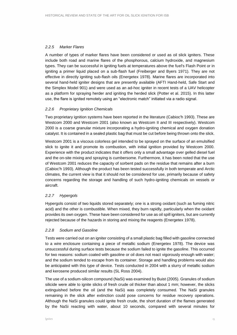
AFTI Igniter
As a result of their experience during the Deepwater Horizon in-situ burning operations, Desmi
has developed a simple hand-held igniter kit (Figure 7) that consists of a cardboard box containing
two empty plastic gallon jugs, polyethylene foam packing, a ballast weight and a receptacle for a
marine flare. The flare and fuel to be gelled (diesel or gasoline) are to be supplied by the customer.
The gelling agent can be supplied either by Desmi or the customer.
The AFTI Igniter is produced and marketed by:
Desmi, Inc. (formerly Applied Fabric Technologies, Inc.) 1119 Cavalier Blvd.
Chesapeake, VA 23323, USA Phone: (757) 857 7041 Fax: (757) 857 6989 E-mail: [email protected]
HISTORICAL REVIEW AND STATE OF THE ART FOR OIL SLICK IGNITION FOR ISB
Igniters 26
Figure 7 AFTI Hand-held Igniter (source: DESMI)
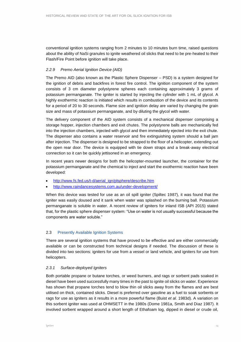
Safe Start Igniter
The Elastec/American Marine Safe Start Igniter (Figure 8) is designed to provide a safe and easy
way to start controlled burns. Each 1 gallon (3.8 L) container is preloaded with non-toxic Safe
Start gelling agent to be mixed with diesel fuel. A common marine flare, when ignited, will melt
the container, allowing the gelled burning fuel to spread to an approximately 1-metre diameter fire
that lasts up to 5 minutes.
Figure 8 Safe Start hand-held igniter. (source: Elastec / American Marine)
The Safe Start Igniter is produced and marketed by:
Elastec American Marine, Inc. 1309 West Main
Carmi, IL USA 62821 USA Tel: 618-382-2525 Fax: 618-384-2740 E-mail: [email protected]
Simplex Model 901 Hand-held
This igniter was used successfully in an experimental burn in 1996 in England. It consists of a 1-
quart polyethylene bottle filled with gelled gasoline. The bottle is fitted with two foam floatation
collars (Figure 9, Table 3), and a marine hand-held distress flare is attached to the outside of the
bottle to provide the ignition source. The flare should be positioned such that it extends 1.5 inches
beyond the bottle: this allows the user to hold the igniter for 10 to 20 seconds and ensure that it
is burning properly before deploying it. The flare is ignited and the device is thrown in front of the

HISTORICAL REVIEW AND STATE OF THE ART FOR OIL SLICK IGNITION FOR ISB
Igniters 27
slick and allowed to drift into it. The flare burns for approximately 1 minute before it burns through
the plastic bottle and ignites the gelled gasoline as it is released from the bottle. The 1-minute
delay allows time for the igniter to drift into the oil slick and for the deployment personnel to
distance themselves from the burn area.
Figure 9 Simplex Hand-held Flare Igniter (Fingas and Punt, 2001)
This device is available from Simplex (contact information below). Alternatively, an ad-hoc version
of this relatively simple device could be made at the time of a spill with readily available materials.
Table 3. Simplex Hand-held Igniter Model 901 Dimensions
Length Width Height Volume Weight
8 in. 8 in. 4 in. 2 ft3 for 12 igniters
Shipping: 5 lb per 12 igniters
Use: 1.5 lb per igniter when full of gelled fuel
Dimensions estimated
Simplex Manufacturing Co. dba Simplex Aerospace 13340 NE Whitaker Way Portland, OR 97230 UNITED STATES Phone: +1 503-257-3511 E-mail: [email protected] Web: www.simplexmfg.com
HISTORICAL REVIEW AND STATE OF THE ART FOR OIL SLICK IGNITION FOR ISB
Igniters 28
2.4 Aerially-deployed Igniters
There are two aerially-deployed igniter systems that are currently available for use on oil spills,
as discussed in the following section (adapted, with permission, from Allen 1986).
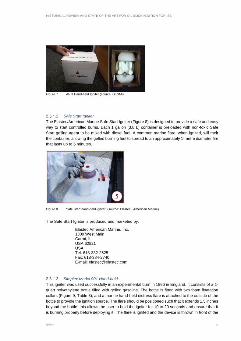
2.4.1 Dome Igniter
The Dome Igniter (also known as the Energetex Igniter) is a lightweight air-deployable pyrotechnic
device developed by Dome Petroleum Ltd., Calgary, Canada, in cooperation with Energetex
Engineering, Waterloo, Canada. The igniter (Figure 10) measures approximately 30 cm by 18 cm
by 11 cm and weights a little over 0.4 kg. The unit consists of a wire-mesh fuel basket with solid
propellant and gelled kerosene slabs suspended between two metal floats. Like the EPS igniter,
the Dome unit is intended as a hand-thrown device.
The Dome Igniter was manufactured by Energetex Engineering and came to be known as the
Energetex igniter or the “tin-can” igniter. It went through several design changes since it was first
tested by Dome during the winter of 1979/80 (Buist et al. 1981). These changes involved the
igniter's mode of activation and the way in which certain components in its fuel basket are isolated
from each other (Energetex 1982b). In order to avoid any need for open flame during activation,
the fuse wire is started with a specially designed electric ignition system referred to as the
Energetex Engineering Ignition System (EElS). Consisting of a 12-volt spill-proof battery with a
gel electrolyte and a heater element, the EElS can provide sufficient heat to activate the igniter's
fuse wire within two seconds of contact. Once started, the 25 cm long safety fuse provides about
45 seconds of delay for throwing the igniter and allowing it to settle within the target oil slick.
Although the Dome igniter is not in common use, it is still held in inventory by some response
organisations and is included in this summary on that basis.
The fuse ignites a thermal igniter wire, which in tum ignites the solid propellant slabs located
above and below the igniter wire. The solid propellant burns intensely for about 10 seconds with
temperatures in excess of 1200°C. During this initial burn, the gelled kerosene begins to burn,
producing temperatures of 700°C to 800° C. The total burn time for the igniter is about 10 minutes.
The device is designed so that the fuel basket housing the propellant and gelled kerosene is
suspended above the oil layer. Oil between the floats and beneath the fuel basket is somewhat
shielded from the wind to allow heating of the oil. The relatively long burn-time for the Dome igniter
helps ignite the slick if winds temporarily separate the igniter from the heaviest concentrations of
oil. Upon completion of the burn, all of the metal components of the igniter remain on the surface
of the water and attached to the two floats.
The low weight and irregular shape of the igniter give the igniter a relatively low terminal velocity
and a tendency to avoid rolling on impact with solid surfaces. The igniter has only two stable
positions in which it can float and either one keeps the igniter's flames in close proximity to and
slightly above the oil.
The fuse wire of the Dome igniter must be kept away from any potential sources of ignition. Once
activated, the igniter cannot be deactivated, and it must be released as soon as possible (at least
20 to 30 seconds before the end of the 45-second delay period). Proper packaging in separate
plastic bags and storage of the units in cardboard boxes onboard the helicopter should be
sufficient to prevent any accidental activation of an igniter.

HISTORICAL REVIEW AND STATE OF THE ART FOR OIL SLICK IGNITION FOR ISB
Igniters 29
Figure 10 Basic design and internal components of the Dome or Energetex igniter (adapted from Allen 1986)
(source: Marine Spill Response Corporation)
Based on the Dome igniter’s explosives classification, it need only be stored in a spark-free, dry
area and be packaged and properly marked as a pyrotechnic firework. The igniters should be
stored in a secure place, safely removed from any heat sources and other flammable materials.
The Dome igniter has undergone rigorous testing (Energetex 1982b) over a broad range of
temperatures (-70°C to 50°C) and vibration and humidity conditions normally used for such
explosives manufactured and used in Canada.
The simplicity of design of the Dome igniter provides a good probability of success. Its starter fuse
and ignition wire have at least 95% reliability, and experience both in the U.S. and Canada
suggests that the probability of activating the entire contents of the fuel basket is in excess of
90%. As with any pyrotechnic device, the probability of success is expected to diminish as the
shelf life of each unit is approached.
HISTORICAL REVIEW AND STATE OF THE ART FOR OIL SLICK IGNITION FOR ISB
Igniters 30
The igniter has been extensively tested and shown to be capable of igniting fresh, weathered and
emulsified oils (up to 60% water) in temperatures as low as -30°C and in winds up to 40 km/h
(Dome 1981b, Energetex 1978, 1979, 1981a, 1982b).
The shelf life of the Dome igniter is estimated at about five years, although experience with igniters
stored in Alaska and Canada has shown that they will operate after 15 to 25 years (Allen 1992,
SL Ross et al. 2003). It is important that any stockpiled igniters be carefully dated, periodically
tested and reconstructed as necessary. Tearing down and replacing the pyrotechnic portion of
the igniter will cost approximately 50% of the original purchase price.
The current manufacturer of the Dome igniter is:
Energetex Engineering
505-125 Lincoln Road
Waterloo, Ontario, Canada, N2J 2N9
Fax: 519-885-2738
2.4.2 Heli-Torch (adapted with permission from Allen 1987)
The Heli-torch (Figure 11) is a proven aerial ignition system commonly used by the U.S. Forest
Service and the Canadian Forestry Service for burning forest slash and for setting backfires during
fire-control operations. It is a completely self-contained unit consisting of a fuel barrel, pump, and
motor assembly slung beneath a helicopter and controlled with an electrical connection from the
Heli-torch to a panel in the cockpit. The fuel barrel can be filled with a gelled gasoline or gasoline
and diesel mix which is then pumped on demand to a positive-control shut-off valve and ignition
tip. The gelled fuel mixture is ignited with electrically-fired propane jets as it exits one or more
nozzles protected by wind shields. The burning gelled fuel falls as a highly viscous stream and
quickly breaks up into individual globules before hitting the ground. Three models are available
with 110 L, 205 L and 1100 L (30, 55 and 300 gal) capacities. Of these, the 205 L (55 gallon)
model has been most extensively tested for use on oil spills.
In fighting forest fires, the Heli-torch may be operated from heights of several hundred feet and
with speeds of 40 to 60 mph (65 to 95 km/h). Such heights and airspeeds are not desirable for
the ignition of oil slicks at sea. Depending upon the actual nature of the slicks to be ignited, flying
at much lower altitudes (8 to 23 metres) and with airspeeds of 40 to 50 km/h may considerably
enhance the accuracy, ignition success and distribution of burning globules.
The Heli-torch ignition system is manufactured by Simplex Aerospace Co. in Portland, Oregon
(www.simplexmfg.com), and is approved by the U.S. Federal Aviation Administration (FAR Part
137). U.S. users of the system are cautioned that certain federal regulations (46 CPR) require
approval by the Office of Hazardous Materials Transportation (OHMT), U.S. Department of
Transportation, for transporting fuel beneath a helicopter (e.g., sling-loaded Heli-torch) and for
transporting the fuel to support a gelling operation at a remote site. Exemptions from these
requirements have been obtained for such operations as forest fire control; nevertheless,
application for exemption involving oil spill control must be requested.

HISTORICAL REVIEW AND STATE OF THE ART FOR OIL SLICK IGNITION FOR ISB
Igniters 31
Figure 11 Heli-Torch Components and Support System (adapted from Allen 1986) (source: Marine Spill Response
Corporation; photo: A. Allen)
The gelling mix used to thicken the gasoline (or diesel as the case may be) often involved
SUREFIRE, a gelling agent available from Simplex (Portland, Oregon) and from Fire-Trol
Holdings, L.L.C. (the exclusive U.S.A. distributor for FIRE-TROL Fuel Gelling Agent, previously
sold as SUREFIRE®).
The Heli-torch can be carried by a helicopter with a cargo hook and a 24-to 28-volt power supply.
When the single-point suspension cable system is used with helicopters employing swivel cargo
hooks (e.g., Bell 250, 212, 412), the Heli-torch may experience temporary rotation. However its
design normally allows the unit to achieve a stable orientation and fly without any loss of its
globule-ignition or distribution characteristics.
Depending upon the helicopter used (i.e., with fixed or swivel cargo hook), the Helitorch support
assembly may be rigged to include a self-releasing horizontal support arm or stabilizing bar to
keep the Heli-torch oriented properly. The stabilizing bar can be suspended at one end directly

HISTORICAL REVIEW AND STATE OF THE ART FOR OIL SLICK IGNITION FOR ISB
Igniters 32
below the cargo hook, with the other end of the bar resting on one of the helicopter's skids. The
Heli-torch's support cable assembly is then connected directly to the stabilizing bar. This approach
provides a stable two-point connection while permitting the Heli-torch to be jettisoned if necessary.
Both support systems (i.e., with and without the stabilizing bar) were used during field trials (Allen
1987).
The weight of the Heli-torch with a full 205 L (55 gallon) drum is approximately 243 kg (534
pounds). The entire unit is connected to a helicopter with a support cable assembly that can be
jettisoned quickly from the helicopter's cargo hook. The electrical cable has a quick-disconnect
plug near the helicopter, and this plug can also be pulled apart easily if the unit is released in an
emergency.
SUREFIRE1 is a fine powder that when mixed with liquid fuel produces a smooth, viscous gel.
When typical ratios of 1.8 to 2.8 kg (4 to 6 pounds) of SUREFIRE to 205 L (55 gallons) of fuel are
used, adequate viscosities for Heli-torch use can normally be achieved within a matter of minutes
at room temperature. At sub-freezing temperatures, ratios of 5 kg (11 pounds) to 205 L (55
gallons) are required for gelling to occur in 30 to 40 minutes. The gelling mix is poured through
the entry port of the Heli-torch fuel storage drum, which is equipped with a hand crank for mixing.
Separate, portable gelled fuel mixing tanks are available from the manufacturer.
The Heli-torch is operated with a positive-displacement pump producing a flow of approximately
55 L/min. When operated with a 205 L holding drum, the Heli-torch can provide a total application
time of about 3 minutes and 40 seconds. The drum would then have to be refilled with gelled fuel
or replaced with another drum already filled. The 205 L Heli-torch model is rigged so that an empty
drum can be removed from the support frame and replaced with a full drum quickly and safely.
Burning gelled gasoline globules released from heights of a few m to 18 m continue burning after
impact. Even without oil on the water's surface, splash effects are tolerable, and elongated
“pancakes” of gelled burning fuel result with sizes (if expressed as a circle) typically 13 to 18 cm
in diameter.
Experience suggests that the average globule sizes produced by the Heli-torch with its standard
nozzle at heights of 20 metres or less will be between 60 and 120 mL. With gelling-mix-to-gasoline
ratios of 2.5 to 5 kg per 205 L of fuel, such globules spread to thicknesses of 6 to 8 mm on oil-
free water surfaces. The globule burn times range between 4 and 6 minutes.
Ignition of fresh and 2-week weathered, unemulsified crude oil layers is possible in winds of 15 to
25 km/h; globules approximately 60 to 120 mL in volume are necessary to prevent blowout of the
flame. During several successful ignitions of crude oil slicks surface winds have reached speeds
of 30 km/h.
Experience (Allen 1992) has shown that the Heli-torch should be flown at altitudes of 8 to 23 m
and with speeds of 40 to 50 km/h. The suggested altitude range is to provide accuracy during the
release, to reduce the loss of gelled fuel while burning in the air, and to prevent the blowout of
smaller globules on the surface by downwash when the helicopter is flying at low speeds. A
minimum speed of 40 km/h is recommended to prevent such blowouts. At altitudes in excess of
30 m downwash is minimal and the Heli-torch can be used in a stationary mode.
It should be noted that some jurisdictions/operators now restrict use of Heli-torch and other
helicopter-slung devices, notably Norway.
1 Also known as FireTrol, EZFire, PetroJel, Alumagel

HISTORICAL REVIEW AND STATE OF THE ART FOR OIL SLICK IGNITION FOR ISB
Igniters 33
Table 4 gives a summary comparison of the two aerial ignition systems discussed above.
Table 4. Summary of Aerial Igniter Characteristics and Performance
ASSESSMENT CRITERIA DOME IGNITER HELI-TORCH (205 L MODEL)
SA
FE
TY
Open flame or sparks inside aircraft
None, if EEIS used. None
Susceptibility to accidental activation
Highly unlikely: requires separate ignition source.
Unlikely: positive off/on control and isolated circuit breaker.
Retrieval and handling of igniters that have misfired
Safe to handle after 2-min. delay. Must return to base to adjust/ repair/replace Heli-torch.
ST
OR
AG
E
Shelf life 5 years (Dome igniters stored 25 to 30 years in Arctic still operating).
N.A.: Flammable mixture prepared at time of need.
Difficulty of replacement (all or in part) following normal shelf life
Simple replacement of pyrotechnic portion only (about 50% of initial <cost).
N.A.
Routine maintenance requirements
None Minimal: pump, valves, stirring equipment, etc.
Susceptibility to high or low temperatures during storage/transit
Very low: tested between -70°C and +50°C.
Gel-mixing process best carried out at or above freezing temperatures.
Susceptibility to vibration or humidity during storage/transit
Very low (meets military requirements).
Vibration not an issue. Fuel must be kept free of water prior to and during mixing.
GO
VE
RN
ME
NT
RE
GU
LA
TIO
NS
Shipping and storage
regulations
Basically treated as fireworks. Housed and locked in non-sparking container, properly marked as fireworks. Shipment by land, sea or chartered aircraft permitted; shipment by commercial passenger aircraft prohibited.
Subject to same storage and transit requirements as for petroleum products. Cannot fly Heli-torch over populated areas (FAR Part 137approved).
AV
AIL
AB
ILIT
Y
Currently stockpiled Approx. 1,700 igniters at Prudhoe Bay (owned by Alaska Clean Seas); approx. 4,000 igniters at Tuktoyaktuk, Canada (owned by Canadian Coast Guard).
Numerous units available in U.S. and Canada.
Resupply capability No longer produced by Energetex Under emergency conditions, approx. 20 Heli-torches per month.
CO
ST
Estimated cost No longer produced by Energetex. Cost $80 to $120 (depending on volume purchased) per unit in 1986.
Approx. $15,000 per application unit.
OP
ER
AT
ION
AL
CO
NS
IDE
RA
TIO
NS
Level of field testing
performed to data
Extensive. Many controlled spills and some actual spills.
Extensive experience on land. Moderate experience with fresh oil on water.
Reliance upon unique
airborne application
device
None Yes. Heli-torch frame and pump assembly.
Igniter (and/or
application system)
None Minor setup. Self-contained package quickly prepared and sling-loaded. Need mixing operations on ground for
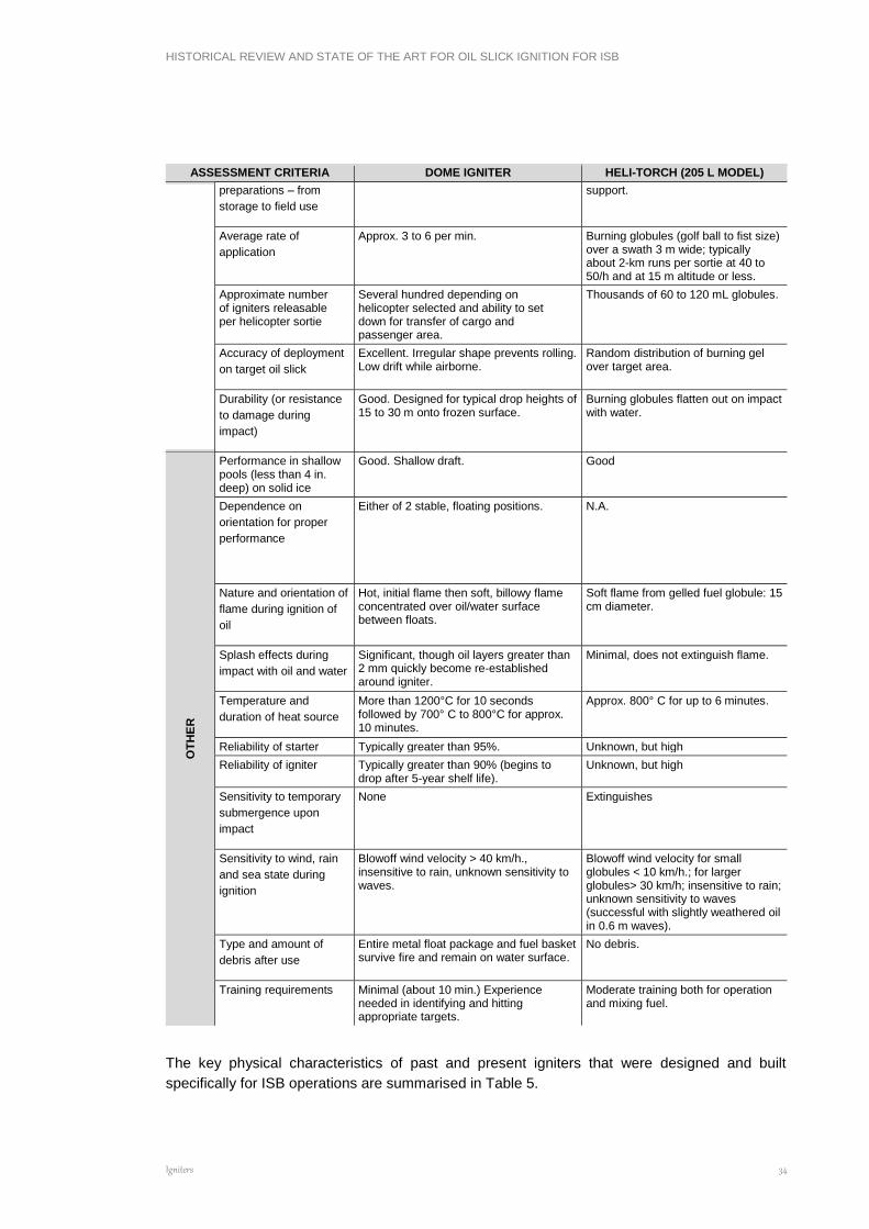
HISTORICAL REVIEW AND STATE OF THE ART FOR OIL SLICK IGNITION FOR ISB
Igniters 34
ASSESSMENT CRITERIA DOME IGNITER HELI-TORCH (205 L MODEL)
preparations – from
storage to field use
support.
Average rate of
application
Approx. 3 to 6 per min. Burning globules (golf ball to fist size) over a swath 3 m wide; typically about 2-km runs per sortie at 40 to 50/h and at 15 m altitude or less.
Approximate number of igniters releasable per helicopter sortie
Several hundred depending on helicopter selected and ability to set down for transfer of cargo and passenger area.
Thousands of 60 to 120 mL globules.
Accuracy of deployment
on target oil slick
Excellent. Irregular shape prevents rolling. Low drift while airborne.
Random distribution of burning gel over target area.
Durability (or resistance
to damage during
impact)
Good. Designed for typical drop heights of 15 to 30 m onto frozen surface.
Burning globules flatten out on impact with water.
OT
HE
R
Performance in shallow pools (less than 4 in. deep) on solid ice
Good. Shallow draft. Good
Dependence on
orientation for proper
performance
Either of 2 stable, floating positions. N.A.
Nature and orientation of
flame during ignition of
oil
Hot, initial flame then soft, billowy flame concentrated over oil/water surface between floats.
Soft flame from gelled fuel globule: 15 cm diameter.
Splash effects during
impact with oil and water
Significant, though oil layers greater than 2 mm quickly become re-established around igniter.
Minimal, does not extinguish flame.
Temperature and
duration of heat source
More than 1200°C for 10 seconds followed by 700° C to 800°C for approx. 10 minutes.
Approx. 800° C for up to 6 minutes.
Reliability of starter Typically greater than 95%. Unknown, but high
Reliability of igniter Typically greater than 90% (begins to drop after 5-year shelf life).
Unknown, but high
Sensitivity to temporary
submergence upon
impact
None Extinguishes
Sensitivity to wind, rain
and sea state during
ignition
Blowoff wind velocity > 40 km/h., insensitive to rain, unknown sensitivity to waves.
Blowoff wind velocity for small globules < 10 km/h.; for larger globules> 30 km/h; insensitive to rain; unknown sensitivity to waves (successful with slightly weathered oil in 0.6 m waves).
Type and amount of
debris after use
Entire metal float package and fuel basket survive fire and remain on water surface.
No debris.
Training requirements Minimal (about 10 min.) Experience needed in identifying and hitting appropriate targets.
Moderate training both for operation and mixing fuel.
The key physical characteristics of past and present igniters that were designed and built
specifically for ISB operations are summarised in Table 5.
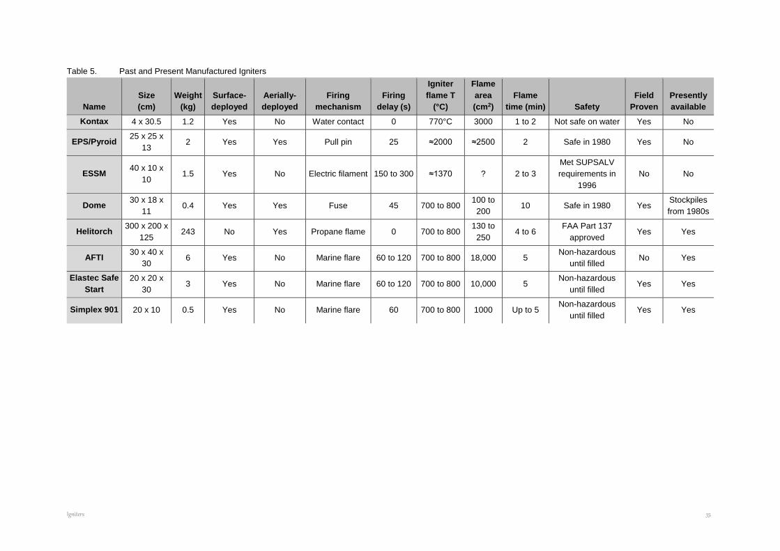
Igniters 35
Table 5. Past and Present Manufactured Igniters
Name
Size
(cm)
Weight
(kg)
Surface-
deployed
Aerially-
deployed
Firing
mechanism
Firing
delay (s)
Igniter
flame T
(°C)
Flame
area
(cm2)
Flame
time (min) Safety
Field
Proven
Presently
available
Kontax 4 x 30.5 1.2 Yes No Water contact 0 770°C 3000 1 to 2 Not safe on water Yes No
EPS/Pyroid 25 x 25 x
13 2 Yes Yes Pull pin 25 ≈2000 ≈2500 2 Safe in 1980 Yes No
ESSM 40 x 10 x
10 1.5 Yes No Electric filament 150 to 300 ≈1370 ? 2 to 3
Met SUPSALV
requirements in
1996
No No
Dome 30 x 18 x
11 0.4 Yes Yes Fuse 45 700 to 800
100 to
200 10 Safe in 1980 Yes
Stockpiles
from 1980s
Helitorch 300 x 200 x
125 243 No Yes Propane flame 0 700 to 800
130 to
250 4 to 6
FAA Part 137
approved Yes Yes
AFTI 30 x 40 x
30 6 Yes No Marine flare 60 to 120 700 to 800 18,000 5
Non-hazardous
until filled No Yes
Elastec Safe
Start
20 x 20 x
30 3 Yes No Marine flare 60 to 120 700 to 800 10,000 5
Non-hazardous
until filled Yes Yes
Simplex 901 20 x 10 0.5 Yes No Marine flare 60 700 to 800 1000 Up to 5 Non-hazardous
until filled Yes Yes
Igniters 36
2.4.3 Fixed-Wing Aerial Ignition System
The ignition of spilled oil from a fixed-wing aircraft has some significant advantages over hand-
held igniters and the use of the Helitorch. Primary advantages include the ability to carry much
larger payloads, typically approaching 1,000 gallons of gelled fuel, and to deliver such payloads
many tens to hundreds of miles from a staging area. A series of “Proof-of-Concept” ground tests
(Preli, et al. 2011) were conducted in 2010 and 2011 to determine whether gelled fuel could be
ignited and achieve a sustained burn at release speeds of 80 to 100 knots, corresponding to the
speed of a small fixed-wing aircraft. The tests were conducted at the Beacon Training Center in
Kenai, Alaska.
Numerous tests were conducted with a variety of nozzle/shroud configurations at temperatures
between 7°C to well below freezing using a trailer-mounted wind machine to simulate the release
of various mixes of gelled fuel (gasoline, diesel, and aviation gas) gelled with Flash 21 gelling
agent. The nozzle/shroud configurations were tested under a variety of orientations downwind to
reduce the relative velocity of the burning gelled fuel globules within the wind-induced (aircraft-
simulated) air. Over two separate week-long test periods the results demonstrated the feasibility
of igniting gelled fuel at simulated fixed-wing aircraft speeds approaching 110 knots.
The safe and effective aerial application of gelled fuel far offshore with large payloads and high
delivery speeds could significantly enhance the ability to conduct controlled burns should spilled
oil be spread over a large and remote area, with or without ice.
2.4.4 Regulatory Requirements
The shipping, storage and use of igniters for ISB will require meeting regulatory requirements.
There may be regulations governing the shipment or storage of igniters or their components by
land, sea or air and some may require special handling (e.g., “Dome” igniters were classified in
the same group of hazardous materials as fireworks, Heli-torch fuel is a petroleum product such
as gasoline and diesel, and the surface-deployed igniters marketed by DESMI, Elastec and
Simplex are specifically designed to be non-hazardous containers that are filled and activated
using easily-obtained components purchased commercially from local sources and added just
before use).
The carriage and use of aerial igniters by aircraft (fixed or rotary wing) will likely require approvals
from the relevant aviation authority. For example, the use of a Heli-torch in the United States
requires that the pilot hold a current US Government training certificate, no passengers be in the
helicopter during operations and the helicopter must avoid flying over populated areas.
The regulations governing the use of in situ burning as an oil spill response tool are the subject
of a separate report in the IOGP JIP Series (http://www.arcticresponsetechnology.org/wp-
content/uploads/2013/10/Report%207.2.1%20-
%20STATUS%20OF%20REGULATIONS%20IN%20ARCTIC%20AND%20SUB-
ARCTIC%20COUNTRIES.pdf).
HISTORICAL REVIEW AND STATE OF THE ART FOR OIL SLICK IGNITION FOR ISB
Summary and Conclusions 37
CHAPTER 3. SUMMARY AND CONCLUSIONS
Successful ignition of oil slicks on water for ISB requires at least 2 to 3 mm of oil thickness to
support combustion, an igniter that heats the oil layer above its Fire Point and provides an open
flame to ignite the oil vapours, and effective flame spreading to cover as much as possible of the
slick.
The presently-available igniters for ISB operations are summarised in Table 6. Of these, the four
that depend on gelled fuel are commercially available: stockpiles of the Dome igniter have existed
in Alaska and Northern Canada since the mid-1980s.
The three hand-held igniters employing gelled fuel require that gelling agent, fuel (gasoline or
diesel) and a marine flare be added onsite in order to be made functional. Since they contain no
hazardous materials prior to being readied, they can be shipped empty without the need for
hazardous material handling and documentation. These igniters are suited to initiating ISB in fire
booms on water with one or two units released in from of, or directly onto the contained oil.
The Helitorch is the only presently-available system for deploying a large number of ignition
sources from the air over larger areas of a spill in a relatively short time. The Helitorch is suitable
for use on oil contained on or among ice, contained by herding agents or contained by fire boom.
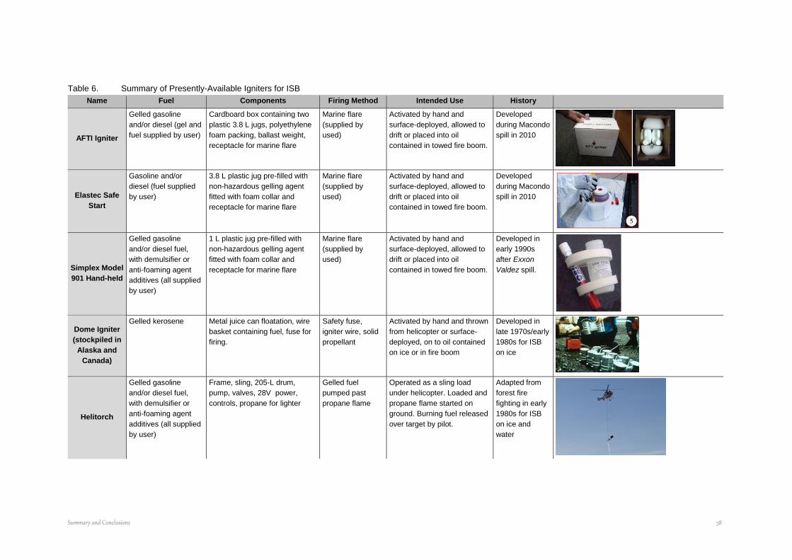
Summary and Conclusions 38
Table 6. Summary of Presently-Available Igniters for ISB
Name Fuel Components Firing Method Intended Use History
AFTI Igniter
Gelled gasoline
and/or diesel (gel and
fuel supplied by user)
Cardboard box containing two
plastic 3.8 L jugs, polyethylene
foam packing, ballast weight,
receptacle for marine flare
Marine flare
(supplied by
used)
Activated by hand and
surface-deployed, allowed to
drift or placed into oil
contained in towed fire boom.
Developed
during Macondo
spill in 2010
Elastec Safe
Start
Gasoline and/or
diesel (fuel supplied
by user)
3.8 L plastic jug pre-filled with
non-hazardous gelling agent
fitted with foam collar and
receptacle for marine flare
Marine flare
(supplied by
used)
Activated by hand and
surface-deployed, allowed to
drift or placed into oil
contained in towed fire boom.
Developed
during Macondo
spill in 2010
Simplex Model
901 Hand-held
Gelled gasoline
and/or diesel fuel,
with demulsifier or
anti-foaming agent
additives (all supplied
by user)
1 L plastic jug pre-filled with
non-hazardous gelling agent
fitted with foam collar and
receptacle for marine flare
Marine flare
(supplied by
used)
Activated by hand and
surface-deployed, allowed to
drift or placed into oil
contained in towed fire boom.
Developed in
early 1990s
after Exxon
Valdez spill.
Dome Igniter
(stockpiled in
Alaska and
Canada)
Gelled kerosene Metal juice can floatation, wire
basket containing fuel, fuse for
firing.
Safety fuse,
igniter wire, solid
propellant
Activated by hand and thrown
from helicopter or surface-
deployed, on to oil contained
on ice or in fire boom
Developed in
late 1970s/early
1980s for ISB
on ice
Helitorch
Gelled gasoline
and/or diesel fuel,
with demulsifier or
anti-foaming agent
additives (all supplied
by user)
Frame, sling, 205-L drum,
pump, valves, 28V power,
controls, propane for lighter
Gelled fuel
pumped past
propane flame
Operated as a sling load
under helicopter. Loaded and
propane flame started on
ground. Burning fuel released
over target by pilot.
Adapted from
forest fire
fighting in early
1980s for ISB
on ice and
water

HISTORICAL REVIEW AND STATE OF THE ART FOR OIL SLICK IGNITION FOR ISB
References 39
CHAPTER 4. REFERENCES
Akita, K. and T. Yumoto. 1965. Heat transfer in small pools and rates of burning of liquid methanol. Tenth Symposium (International) on Combustion. The Combustion Institute, Pittsburgh, PA. pp. 943-948.
Allen, A.A. 1986. Alaska Clean Seas survey and analysis of air-deployable igniters. Proceedings of the Ninth Arctic and Marine Oilspill Program Technical Seminar, June 10-12, Edmonton, Alberta. Environment Canada, Ottawa, Ontario. pp. 353-373.
Allen, A.A. 1987. Refinement of aerial ignition systems, (test and evaluation of the Heli-torch for the ignition of oil slicks). Report to Alaska Clean Seas, Anchorage, Alaska.
Allen, A.A. 1991. Controlled burning of crude oil on water following the grounding of the Exxon Valdez. Proceedings of the 1991 Oil Spill Conference, March 4-7, San Diego, California. American Petroleum Institute, Washington, D.C. pp. 213-216.
Allen, A.A. 1990a. Contained controlled burning of spilled oil during the Exxon Valdez oil spill. Proceedings of the Thirteenth Arctic and Marine Oilspill Program Technical Seminar, June 6-8, Edmonton, Alberta. Environment Canada, Ottawa, Ontario. pp. 305-313.
Allen, A.A. 1990b. Contained controlled burning of spilled oil during the Exxon Valdez oil spill. Spill
Technology Newsletter, vol. 15, no. 2, pp. 1-5.
Allen, A.A. 1992. In-situ burning field operations manual. 3M Ceramic Materials Department. St. Paul, MN.
Anonymous. 1967. Chemicals vs. crude oil. Chemical Week 100(20):49.
American Petroleum Institute (API). 2015. Field Operations Guide for In-Situ Burning of Inland Oil Spills. API Technical Report 1251 First Edition, July 2015 API Washington, D.C.
Battelle. 1979. Combustion: An oil spill mitigation tooL Report for U.S. Department of Energy, Contract No. EY-76-C-06-1830, U.S. Dept. of Energy, Washington, D.C.
Bech, C., P. Sveum, and LA. Buist. 1992. In-situ burning of emulsions: the effects of varying water content and degree of evaporation. Proceedings of the Fifteenth Arctic and Marine Oilspill Program Technical Seminar, June 10-12, Edmonton, Alberta. Environment Canada, Ottawa, Ontario. pp. 547-559.
Bech, C., Sveum, P. and Buist, I.A. 1993. The effect of wind, ice and waves on the in-situ burning of emulsions and aged oils. Proceedings of the Arctic and Marine Oilspill Program Technical Seminar No. 16, Vol. 2, Environment Canada, Ottawa, pp. 735-748.
Buist, I. 2005: Preliminary screening of the potential for Sodium Silicide to ignite oil slicks. ExxonMobil Upstream Research, Houston.
Buist, I., W. Pistruzak, and D. Dickins. 1981. Dome Petroleum's oil and gas under sea ice study. Proceedings of the Fourth Arctic and Marine Oilspill Program Technical Seminar, June 16-18, Edmonton, Alberta. Environment Canada, Ottawa, Ontario. pp. 647-686.
Buist, LA., W.M. Pistruzak, S.G. Potter, N. Vanderkooy, and I.R. McAllister. 1983d. The development and testing of a fireproof boom. Proceedings of the Sixth Arctic and Marine Oilspill Program Technical Seminar, June 14-16, Edmonton, Alberta. Environment Canada, Ottawa, Ontario. pp. 70-84.
Cabioc'h, F. 1993. Last French experiments in order to evaluate the burning possibilities of three water-in-oil emulsions. Proceedings of the Sixteenth Arctic and Marine Oilspill Program Technical Seminar, June 7-9, Calgary, Alberta. Environment Canada, Ottawa, Ontario.
Coupal, B. 1972. Use of peat moss in controlled combustion technique. Environment Canada, Ottawa, Ontario. Environment Canada Report No. EPS 4-EE-72-1, 32 p.
Det norske Veritas. 1979. Tanker oil spill analysis study. Technical report for Canadian Marine Drilling Limited. Det norske Veritas Ship Division.
Dickins, D. F. 1979. Air deployable oil spill igniter tests - Yellowknife. Arctic Petroleum Operators Association Project 164.
Dome Petroleum Ltd. 1981. Oil and gas under sea ice. Final report volume one. Report to COOSRA. Calgary, Alberta.
Dome Petroleum Ltd. 1981a. Fire proof boom development -Ohmsett trials. 27 p. Dome Petroleum Ltd., Calgary, Alberta.
HISTORICAL REVIEW AND STATE OF THE ART FOR OIL SLICK IGNITION FOR ISB
References 40
Energetex Engineering. 1978. Testing of air-deployable incendiary devices for igniting oil on water. Environment Canada, Ottawa, Ontario. Report No. EPS-4-EC-78-11. 98p.
Energetex Engineering. 1979. A review of oil slick combustion promoters. Environment Canada, Ottawa, Ontario. Environment Canada Report EPS-3-EC-79-8. 48 p.
Energetex Engineering. 1980. A study to evaluate the combustibility and other physical and chemical properties of aged oils and emulsions. Report to Environment Canada, Ottawa.
Energetex Engineering. 1981. Burning of crude oil under wind herding conditions. Report prepared for Canadian Marine Drilling Ltd.
Energetex Engineering. 1982a. Improvement of air-deployable oil slick igniters. Arctic Petroleum Operators Association Project 165. APOA, Calgary, Alta.
Energetex Engineering. 1982b. Environmental testing of Dome air-deployable igniter. Final report prepared for Dome Petroleum Ltd. 28 p.
Evans, D., H. Baum, B. McCaffrey, G. Mulholland, M. Harkleroad, and W. Manders. 1986. Combustion of oil on water. Proceedings of the Ninth Arctic and Marine Oilspill Program Technical Seminar, June 10-12, Edmonton, Alberta. Environment Canada, Ottawa, Ontario. pp. 301-336.
Evans, D.D., G. Mulholland, D. Gross, H. Baum, and K. Saito. 1988. Burning, smoke production, and smoke dispersion from oil spill combustion. Proceedings of the Eleventh Arctic and Marine Oilspill Program Technical Seminar, June 7-9, Vancouver, British Columbia. Environment Canada, Ottawa, Ontario. pp. 41-87.
Evans, D., W. Walton, H. Baum, K.A. Notarianni, J.R. Lawson, H.C. Tang, K.R. Keydel, R.G. Rehm, D. Madrzykowski, and R.H. Zile. 1992. In-situ burning of oil spills: Mesoscale experiments. Proceedings of the Fifteenth Arctic and Marine Oilspill Program Technical Seminar, June 10-12, Edmonton, Alberta. Environment Canada, Ottawa, Ontario. pp. 593-657.
Fingas, M.F., G. Halley, F. Ackerman, R. Nelson, M. Bissonnette, N. Laroche, P. Lambert, P. Jokuty and K. Li, N. Vanderkooy, W. Halley, G. Warbanski, P.R. Campagna, R.D. Turpin, M.J. Trespalacios , D. Dickins, E.J. Tennyson, D. Aurand, R. Hiltabrand. 1994. The Newfoundland offshore burn experiment - NOBE, experimental design and overview. Proc. of the 17th Arctic and Marine Oilspill Program Technical Seminar, p1053. Environment Canada, Ottawa.
Freiberger, A. and J.M. Byers. 1971. Burning agents for oil spill cleanup. Proceedings of the 1971 Conference on Prevention and Control of Oil Spills, June 15-17, Washington, D.C. American Petroleum Institute, Washington, D.C. pp. 245-251.
Frish, M., V. Gauthier, T. Frank, and P. Nebolsine. 1989. Laser ignition of oil spills: telescope assembly and testing. Environment Canada, Ottawa. Environment Canada report EE-l13.
Fritt-Rasmussen, J., and Brandvik, P.J. 2011. Measuring ignitability for in situ burning of oil spills weathered under Arctic conditions. From laboratory studies to large-scale field experiments. Marine Pol. Bul., 62, 8, 1780-1785.
Glassman, I. and J.G. Hansel. 1968. Some thoughts and experiments on liquid fuel spreading, steady burning and ignitability. Fire Research Abstracts and Reviews 10(3):217-234.
Glassman, I., J.G. Hansel, and T. Eklund. 1969. Hydrodynamic effects in the flame spreading, ignitability and steady burning of liquid fuels. Combustion and Flame 13:99-101.
Guenette, C.C. and J. Thornborough. 1997: An assessment of two offshore igniter concepts. Proc. of the 20th Arctic and Marine Oilspill Program Technical Seminar, p795. Environment Canada, Ottawa.
Guenette, C., P. Sveum, I. Buist, T. Aunaas and L. Godal. 1994. In-situ burning of water-in-oil emulsions. SINTEF Report STF21 A94053. SINTEF Applied Chemistry, Trondheim, Norway. p139.
Hess, Thomas J., Ilene Byron, Heather Warner Finley, Charles B. Henry. 1997. The Rockefeller Refuge oil spill: a team approach to incident response. Proc. of the 1997 International Oil Spill Conference, p817. American Petroleum Institute. Washington, D.C.
Hossain, K. and D. MacKay. 1981. A study of the combustibility of weathered crude oils and water-in-oil emulsions. Environment Canada, Ottawa, Ontario. Environment Canada Report EE-12, 43 p.
Kanury, A.M. 1988. Ignition of liquid fuels. SFPE Handbook of Fire Protection Engineering. National Fire Protection Association, Quincy, MA. pp. 1.315-1.325.
Laisk, E. 1976. Feasibility of oil slick removal from seawater using power lasers. Environmental Science and Technology 10(8):814-815.

HISTORICAL REVIEW AND STATE OF THE ART FOR OIL SLICK IGNITION FOR ISB
References 41
Mabile, Neré. 2010. Fire Boom performance evaluation: controlled burning during the Deepwater Horizon Spill operational period. BP Americas. Houston.
Mackinven, R, J.G. Hansel, and I. Glassman. 1970. Influence of laboratory parameters on flame spread across liquid Fuels. Combustion Science and Technology 1(4):293-306.
May, Victoria L. and James R. Wolfe. 1997. Field experience with controlled burning of inland oil spills. Proc. of the 1997 International Oil Spill Conference, p811. American Petroleum Institute. Washington, D.C.
Maybourn, R 1971. The work of the IP working group on the burning of oil. Journal of the Institute of Petroleum 57:12-16.
Meikle, K. 1981a. An oil slick igniter for remote areas. Proceedings of the 1981 Oil Spill Conference, March 2-5, Atlanta, Georgia. American Petroleum Institute, Washington.
Meikle, K.M. 1981b. Incendiary device for oil slick ignition. Proceedings of the Fourth Arctic and Marine Oilspill Program Technical Seminar, June 16-18, Edmonton, Alberta. Environment Canada, Ottawa, Ontario. pp. 499-513.
Moffatt, C. and P. Hankins 1997. Results of experiments with flare type igniters on diesel fuel and crude oil emulsions. Proc. of the 20th Arctic and Marine Oilspill Program Technical Seminar, p1197. Environment Canada, Ottawa.
Murad, R.J., J. Lamendola, H. Isoda, and M. Summerfield. 1970. A study of some factors influencing the ignition of a liquid fuel pool. Combustion and Flame 15(3):289-298.
Murty, K.A. 1988. Ignition of liquid fuels. The SFPE Handbook of Fire Protection Engineering; Quincy, MA: National Fire Protection Association; pp. 1.315-1.325.
Potter, S., I. Buist, D. Cooper, W. Schnabel, J. Garron, R. Perkins, S. Aggarwal, R. Bullock and P. Lane. 2015. Field Research on Helicopter Application of Chemical Herders to Advance In situ Burning. Report to IOGP JIP on Arctic Response Technology, in press.
Preli, T.A., Allen, A.A., & D. Glenn 2011. Development of High Speed Aerial Ignition Techniques For In Situ Burning, Paper delivered at the Arctic Technology Conference during the Offshore Technology Conference, Houston, Texas, February 7-9, 2011.
Ruby, C.H., L.G. Ward, l.A. Fischer, and P.J. Brown. 1978. Buzzards Bay oil spill -an arctic analogue. International Conference on Ports and Ocean Engineering under Arctic Conditions (POAC '77), 4th Conference, S1. John's, Newfoundland, 1977
Schrier, E. and C. Eidam. 1979. Cleanup efficiency of a fuel oil spill in cold weather. Proceedings of the 1979 Oil Spill Conference, March 19-22, Los Angeles, California. American Petroleum Institute, Washington, D.C. pp. 419-427.
Sirignano, W.A. and I. Glassman. 1970. Flame spreading above liquid fuels: surface-tension driven flows. Combustion Science and Technology 1:307-312; 1969.
SINTEF and S.L. Ross. 1993. In-situ burning of water-in-oil emulsions. Report to NOFO et al., Stavanger,
Norway.
S.L. Ross Environmental Research Ltd. 1989. Disposal of spilled Hibernia crude oils and emulsions: In-situ burning and the "Swirlfire" burner. Report to Canadian Coast Guard, Ottawa.
S.L. Ross Environmental Research Ltd. 1995. Demulsifiers and modified heli-torch fuels to enhance in-situ
burning of emulsions. Report to ACS, Prudhoe Bay, AK.
S.L. Ross Environmental Research Ltd. 1997. Laboratory testing to determine operational parameters for in situ burning of six U.S. OCS crude oils. Draft report to the Minerals Management Service. Herndon, VA.
S.L. Ross Environmental Research Ltd. 2004. Preliminary Screening Tests of the Feasibility of Using Slurried Metallic Sodium as an Igniter for Thin Oil Slicks in Ice-Covered Waters. Report to ExxonMobil Upstream Research, Houston, TX.
S.L. Ross Environmental Research Ltd. and Energetex Engineering. 1986. In-situ burning of uncontained oil slicks. EETD report EE-60 revised. Environment Canada, Ottawa.
Smith, N.K. and A. Diaz. 1985. In-place burning of crude oil in broken ice -1985 testing at Ohmsett. Proceedings of the Eighth Arctic and Marine Oilspill Program Technical Seminar, June 18-20, Edmonton, Alberta. Environment Canada, Ottawa, Ontario. pp. 176-191.
HISTORICAL REVIEW AND STATE OF THE ART FOR OIL SLICK IGNITION FOR ISB
References 42
Smith, N.K. and A. Diaz. 1987. In-place burning of crude oils in broken ice. Proceedings of the 1987 Oil Spill Conference, April 6-9, Baltimore, Maryland. American Petroleum Institute, Washington, D.C. pp. 383-388.
Swift, W.H., C.J. Touhill, and P.L. Peterson. 1968. Oil spillage control. Chemical Engineering Progress Symposium Series 65(97):265-273.
Thornborough, J. 1997. United Kingdom in-situ burn trials, Lowestoft, 1996. Proc. of the 1997 International Oil Spill Conference, p131. American Petroleum Institute. Washington, D.C.
Torrance, K.E. and RL. Mahajan. 1974. Fire spread over liquid fuels: liquid phase Parameters. Fifteenth Symposium (International) on Combustion. The Combustion Institute, Pittsburgh, PA. pp. 281-287.
Twardawa, P. and G. Couture. 1983. Incendiary devices for the in-situ combustion of crude oil slicks. DND DREV report 4282/83. Environment Canada, Ottawa.
Waterworth, M.D. 1987. The laser ignition device and its application to oil spills. Proceedings of the 1987 Oil Spill Conference, April 6-9, Baltimore, Maryland. American Petroleum Institute, Washington, D.C. pp. 369-372.
Whittaker, H. 1987. Laser ignition of oil spills. Proceedings of the 1987 Oil Spill Conference, April 6-9, Baltimore, Maryland. American Petroleum Institute, Washington, D.C. pp. 389-394.
Williams, G.W., R. Gondek, A.A. Allen, and J. Michel. 2003. Use of in situ burning at a diesel spill in wetlands and salt flats, northern Utah, USA: Remediation operations and 1.5 years of post-burn monitoring. In: Proceedings of the 2003 International Oil Spill Conference, American Petroleum Institute Publ. No. 14730 A (CD-ROM).
Wu, N., M. Baker, G. Kolb, and J.L. Torero, Ignition, Flame Spread and Mass Burning Characteristics of Liquid Fuels on a Water Bed, Proceedings of the Twentieth AMOP Technical Seminar, Environment Canada, Ottawa, ON, pp. 769-793, 1997.


