
Malaysian Journal of Civil Engineering 25 Special Issue(1):95-111 (2013)
All rights reserved. No part of contents of this paper may be reproduced or transmitted in any form or by any means
without the written permission of Faculty of Civil Engineering, Universiti Teknologi Malaysia
HYBRID SANDWICH PANEL WITH NATURAL FIBRE COMPOSITE
INTERMEDIATE LAYER: MANUFACTURING PROCESS AND
SIGNIFICANCE ANALYSIS
Jauhar Fajrin*, Yan Zhuge, Frank Bullen & Hao Wang
Centre of Excellence in Engineering Composite (CEEFC), University of Southern Queensland
(USQ), Toowoomba 4350, Queensland, Australia
*Corresponding author: [email protected]
Abstract: Natural fiber reinforced plastic (NFRP) has drawn more attention as an alternative
materials, particularly when dealing with the concept of green or sustainable building. Although
many efforts have been introduced, most results remain unsatisfied either structurally or
economically. In this study, NFRP laminates were incorporated as the intermediate layer of
hybrid structural insulated panels (hybrid SIPs). Two types of natural fibers, Jute and Hemp,
were used to produce laminates for the intermediate layer. A total of 24 panels samples were
tested using 4 point bending load scheme under half and full scale model followed by a statistical
analysis of the results. The result shows the potential of using NRFP to improve the structural
properties of hybrid SIPs.
Keywords: natural fibre reinforced plastics (NFRP); hybrid structure; building construction;
SIPs
1.0 Introduction
The concept of green or sustainable building has now been a popular term in
construction industry as the awareness of environment protection continues to rise. The
key principles relate to the ecological sustainability of building are such as the use of
raw materials based on renewable resources, products are easily recycled and are
economic during the construction process (Berge, 2009). The concept of sustainable
material integrates a variety of strategies during design, construction and site operation.
The term of sustainable or sustainability has many definitions, adaptations and
applications. The most common and widely accepted meaning can be adopted from the
term of sustainable development which is defined as a meeting the needs of the present
without compromising the ability of the future generations to meet their own needs
(WCED in UN-Habitat, 2008).
In relation to the above principles of sustainability, natural fibers are a major renewable
resource material throughout the world specifically in the tropics. According to the
96 Malaysian Journal of Civil Engineering 25 Special Issue(1):95-111 (2013)
Food and Agriculture Organization (FAO) survey, natural fibers like jute, sisal, coir, and
banana are abundantly available in developing countries such as India, Srilangka,
Thailand, Indonesia, Bangladesh, Philippine, Brazil, and South African. Recent reports
indicate that plant fibers can be used as reinforcement in polymer composite to replace
more expensive and non-renewable synthetic fibers such as glass especially in low
pressure laminating (Mathur, 2006).
Currently, natural fiber reinforced composites have drawn more attention as alternative
building materials, especially as wood substitutes in the developing countries. The
concept of using natural fiber in building components is not entirely new as it has been
reported in the early seventies. The construction of cheap primary school building using
jute fiber reinforced polyester in Bangladesh (1972-73) under the support of CARE and
UNIDO is considered as a first effort in the use of natural fiber composite in developing
countries. In the 80s, building panels and roofing sheets made from bagasse/phenolic
were installed in houses in Jamaica, Ghana and Philippines. In another program,
developmental work on low cost building materials based on henequen, palm and sisal
fibers and unsaturated polyester resin had been undertaken as a co-operative research
project between Government of Mexico and UNIDO for appropriate utilization of
natural resources. In the 90s, UNDP in association with the government of India
supported a program to develop jute based composite and moulded products as wood
substitutes in packaging building sectors (Mathur, 2006). The use of natural fibers as
reinforcement in a cement matrix has also been practiced for developing cheap building
materials such as panels, claddings, roofing sheets and tiles, slabs and beams.
More recent efforts relating to the application of NRFP in building construction are as
follows. Burgueno et al., (2004) reported their study which demonstrated that bio-
composites could be used for load-bearing components by improving their structural
efficiency through cellular material arrangements. Laboratory-scale periodic cellular
beams and plates were made from industrial hemp and flax fibers with unsaturated
polyester resin. Material and structural performance was experimentally assessed and
compared with results from short-fiber composite micro-mechanics models and
sandwich analyses. Short-term analytical evaluation of full-scale cellular bio-composite
components indicated that they were compatible with components made from conventional materials. Dweib et al. (2006) manufactured a bio-based roof structure. Cellulose fibers were successfully mixed with soy oil-based resin to form composite structural panels. The cellular fibers were in the form of paper sheets made from recycled cardboard boxes. The panels were prepared using a modified VARTM process. The result provided from beam test shows that the stiffness and strength meet the requirement for roof construction. In addition, Uddin et al. (2011) developed a natural fiber reinforced polymeric structural insulated panels (NSIPs) for panelized construction. This structural sandwich panel is made of jute reinforced polypropylene laminates skins separated by a
Malaysian Journal of Civil Engineering 25 Special Issue(1):95-111 (2013) 97
expanded polystyrene (EPS) foam core. Structural characterizations were performed
using flexural and low velocity impact (LVI) tests. Both test results show the potential
of NSIPs concept to serve as an alternative to OSB SIPs and G/PP SIPs in structural
application such as flooring and walls.
Although many efforts have been introduced, most results remain unsatisfied either
structurally or economically. A bio-based building component with higher structural
performance is normally achieved at the expense of significantly higher cost as we need
to provide a larger size. On the other hand, reducing the size to maintain normal cost
will only produce building component with lower structural performance which may not
competitive with the conventional building materials. For instance, Singh et al. (2005)
stated that manufacturing of single layered natural fiber based panels as the alternative
for plywood has failed to posses desired properties as building materials. The specific
strength, stiffness and dimensional stability were inadequate. In order to cope with this
problem, a composite laminate from hybrid natural fibers was developed. This product
can be prepared using different type of natural fibers such as sisal, jute, coir mats and
unsaturated polyester, phenolic or polyurethane resins.
In order to deal with those shortcomings, Sarah et al. (2009) suggested modifying the
shape of structural components to overcome the nature of large deflection performance
of natural fiber composites due to their low modulus of elasticity, or involving
hybridization at both the constituent and structural levels as advised by Drzal et al.
(2004). This paper presents a new concept of applying NFRP in a building component
namely hybrid structural insulated panels. The basic concept, manufacturing process and
the results provided from experimental testing will be discussed thoroughly.
2.0 Research Concept, Sample Fabrication and Testing Program
2.1 Research Concept
As an alternative to conventional brick and concrete construction, structural insulated
panels (SIPs) have proven their ability for load bearing building construction. The
nature of SIPs is a sandwich structure that consists of two skins separated by a thick-
lightweight core. The current most employed skin is an oriented strand board (OSB) due
to their ease of manufacturing and availability. Some advantages of SIPs with OSB skin
are such as cost and energy efficient as well as require less construction and
maintenance time. On the other hand they also have some drawbacks that limited their
use. The organic nature of OSB skin laid them under the risk of mold build-up and
termite attack and environment changes. The poor water resistance properties of OSB
can lead them to be adversely affected by the presence a flood. Following the hurricane
Katrina in New Orleans in 2005, that damaged many houses built with OSB SIPs due to
windborne missiles, several advancements were introduced to swap the conventional
OSB skin using advanced composite laminates and metal. Laminates made of
98 Malaysian Journal of Civil Engineering 25 Special Issue(1):95-111 (2013)
glass/polypropylene, carbon/epoxy or glass epoxy have been introduced which have
excellent properties to replace OSB (Vaidya et al., 2008). Other effort is the replacement
of the OSB material with metal based skins such as steel and aluminium to produce
more durable and tougher structural insulated panel that is known as metal SIPs
(www.permatherm.net).
Both alternative materials for OSB replacement, composite and metal based skin, are
actually excellent in term of strength and durability. However, in building construction
those two factors are not only the concern when comes to the final production line due
to many compete products have been released to the market. One important thing that
needs to be concerned is a cost effective issue, a new product must have a competitive
price with conventional products. The presence of glass and carbon fiber in composite
laminates skin and aluminium or steel in metal skin are questionable when cost and
environmental-friendly concern comes in to consideration. In addition, the presence of
very thin skin in metal based SIPs for cost reduction reason creates a particular problem
when combined with low density EPS core. For that reason, there has still a need to
develop a new material for producing more durable, effective and efficient SIPs. In this
work we employed a hybrid concept in developing new-hybrid structural insulated
panels.
A combination of two or more materials in a predetermined geometry and scale,
optimally serving a specific engineering purpose is called as a hybrid material. However,
there has a certain duality about the way in which hybrids are observed. Ashby et al.
(2003) mentioned that sandwich structure is an example of hybrid material that reflects
duality, sometimes it is regarded as a structure that consists of two skins with a thick
core layer in the middle, but occasionally it is also viewed as a bulk material that has its
own density, stiffness and strength. The concept introduced in this work can be
explained as follows. A natural fiber reinforced plastics (NFRP) laminate is placed as an
intermediate layer in between aluminium skin and EPS core to produce a hybrid SIPs as
shown in Fig. 1. Hence, this new structure is a combination of two components, SIPs
with aluminium skins as an integrated sandwich structure and intermediate layer
laminates made of NFRP that resulting in a hybrid structure. When we consider a
monolithic panel made upon a homogeny material subjected to a loading scheme, the
typical normal stress distribution is a straight diagonal lain from the top surface to the
bottom. The stress distribution, however, will have a considerable transform at the top
and bottom interface between skin and core layers when the panel in the form of
sandwich structure. Many authors addressed this broadly gap as the causes of the
structure’s early failure. The idea of introducing intermediate layer, which has moderate
properties between the skins and core, is likely to reduce this gap.
This concept can be simply explained based upon the Hooke’s law which implies that
the stress is the function of material’s modulus of elasticity. When the intermediate
layers placed in between, the gap between high and low stress configurations of skins

Malaysian Journal of Civil Engineering 25 Special Issue(1):95-111 (2013) 99
and core can be reduced adequately because the elastic modulus of intermediate layers
has the value between the two classical sandwich constituents. This material
configuration, i.e. two layers of skins and intermediate layers at the top and bottom and
the core in between, is theoretically generating a higher flexural strength for the
sandwich beam.
Figure 1: Typical stress distribution in conventional SIPs (above) and hybrid SIPs (below)
The concept has been developed based on the previous work of Steeves et al. (2004) and
Mamalis et al. (2008). The failure of a sandwich structure is a very complicated
phenomenon. This complication may be due to various failure mechanisms in one of the
materials that compose the structure. These failure mechanisms have been analyzed and
tested and can be summarized as follows (Mamalis, 2008):
Face micro-buckling :
(1)
Face wrinkling :
(2)
Core shear :
(3)
Indentation
(4)
or
(5)
τc : shear strength
σf : compressive strength
b : width of the sandwich panels
E : elastic modulus
G : foam core shear modulus
L : span between supports
Compression
Tension
Face sheet
Face sheet
Core Neutral axis
Compression
Tension
Face sheet
Face sheet
Intermediate layer
Intermediate layer
Core Neutral axis
100 Malaysian Journal of Civil Engineering 25 Special Issue(1):95-111 (2013)
P : load
t : thickness
f : face sheet
c : core
I : internal layer
2.2 Sample Fabrication Using Vaccum Bagging Method and Testing Program
A vacuum bagging process was used for preparing natural fibre laminates. In a manual to
the principle s and practical application of vacuum bagging for laminating a composite
materials published by West System® Epoxy, vacuum bagging (or vacuum bag
laminating) is defined as a clamping method that uses atmospheric pressure to hold the
adhesive or resin-coated components of a lamination in place until the adhesive cures.
Vacuum bagging uses atmospheric pressure as a clamp to hold fiber and matrix together
within an airtight envelope. More simple description about vacuum bag moulding is the
process that combines manual method using hand-layup or spray-up on the open mould
to produce a laminated component followed by a vacuum process after covering the
laminated using polymeric sheet (Kaynak et al., 2001). The current available modern
adhesives that can be cured at room temperature have helped to make vacuum bag
laminating techniques economically available by eliminating the need for much of the
sophisticated and expensive equipments required for laminating in the past. This method
offers many advantages over others available method such as the possibility of
controlling matrix content, produce custom shapes and allows to complete the laminating
process in one efficient operation. It also delivers a firmly and evenly distributed pressure
over the entire surfaces regardless of the nature or amount of material being laminated.
The procedures for vacuum bagging process that used in this experiment are as follows.
1) This process was started by preparing all the materials to be laminated. Jute
woven and hemp mat were cut into required shape and placed in the mold. In
the same time, a release fabric, breathe material and vacuum bag were also
cut to size. The vacuum bag was cut 20% larger than the mold dimensions.
2) The second step was applying the mold release to the mold and shelf surface
followed by applying mastic sealant to the mold perimeter. The sealant was
firmly pressured and overlapped to avoid the existence of gaps.
3) The surface of the mold base then wetted out with the matrix (mixed epoxy
resin and hardener) and the first layer of fiber mat was put on the top of it.
The matrix then poured on the top of the fiber mat and firmly spread out
prior to place the subsequent fiber mat. This process was repeated several
times until the required thickness had achieved. This process needs to be

Malaysian Journal of Civil Engineering 25 Special Issue(1):95-111 (2013) 101
done carefully since once the epoxy mixed the time limit for the entire
process is established.
4) The excess epoxy was then squeezed from each layer after it was wetted out.
The excess epoxy on the fibre mat was rolled out to make sure there had no
puddles of epoxy or air pocket under the fibre mat. When properly wet out, a
puddle of epoxy will appear around the edges of a thumb print after a few
pounds of pressure with a roller.
5) A layer of release fabric was then placed over the laminate followed by a
layer of breathe material. The release fabric will peel off the cured laminate
leaving a fine textured surface. It will also absorb the excessive epoxy that
can be removed after curing. The breathe material, a polyester blanket, that
placed above the release fabric allows the air to pass through the fibres to the
port and absorbs excess epoxy that passes the release fabric.
6) The vacuum bag was then placed over the mold and sealed to the mold
perimeter. The protective paper was then peeled from the mastic sealant
starting at the corner of the mold. The edge of the bag has to be firmly
pressed on to the mastic sealant while pulling the bag taut enough to avoid
wrinkles. Since the bag perimeter is larger than the mold, we need to create
several folds of excessive material as the bag sealed around the mold.
7) The folds of excess bag were then sealed with a strip of the fold. This
process was repeated wherever the fold exists around the mold.
8) The next process was connecting the vacuum line to the bag with a vacuum
port. The vacuum port used here was basically a suction cup with a hole
through it, attached to the end of the line. A small hole was punctured and
the port was attached to the bag over the hole. Breather fabric provides a
path to the port inside the bag over a wide area. We need to place an extra
layer or two of breather under the port.
9) After all the previous procedures done, the vacuum pump was then turned
on to begin evacuating air from the bag. If necessary, temporarily shut off the
vacuum to reposition laminate or adjust the bag. As the air is removed from
the bag, we need to listen for leaks around the bag perimeter, particularly at
the folds in the bag, laps in the mastic and at the vacuum line or port
connection.
10) After the laminate curing thoroughly, the vacuum bag breather and release
fabric were entirely removed from the mold. The laminate was separated
from the mold by inserting small wooden or plastic wedges between the edge

102 Malaysian Journal of Civil Engineering 25 Special Issue(1):95-111 (2013)
of the laminate and the mold.
Once the laminates ready, they were cut into required size to make SIPs samples for
structural testing. The experimental testing in this study was aimed at providing the
information whether introducing natural fiber composite laminates as the
intermediate layer would or would not significantly improve the structural properties
of hybrid structural insulated panels. Hence, the testing program was designed as a
single factor experiment with 3 levels in which two different types of natural fibre
laminates were employed as the intermediate layer of SIPs with aluminium skin and
EPS core. Each type of intermediate layer has played the role for a variable or factor
in the experimental design which is called a qualitative factor. Those two variables
or factors were compared to a control which was a conventional SIP without
intermediate layer. The size of the samples was produced into two categories or
scales; full scale and a half scale while maintaining its aspect ratio. The full scale
model refers to as the minimum size of metal SIPs that currently available in the
market. The testing results were then analyzed using statistics software Minitab 15.
For the purpose of analysis, those factors were leveled as 0, 1 and 2 as required by
Minitab software. For a half scale model, level 0 was the SIPs without intermediate
layer or control level while level 1 and 2 refer to as Hemp fiber composite (HFC)
and Jute fiber composite (JFC), respectively. In full scale scheme, level 1 and 2
refer to as Jute fiber composite (JFC) and Medium Density Fibre (MDF) while level
0 was control factor which is the SIPs without intermediate layer. The beam SIPs
samples were fabricated in accordance with ASTM C 393-00 which is a standard
test method for flexural properties of sandwich constructions. The equipments for
vacuum bagging process used in this study are as shown the Fig. 2.
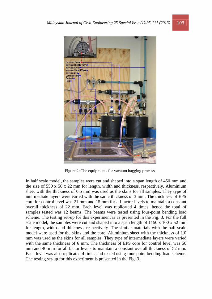
Malaysian Journal of Civil Engineering 25 Special Issue(1):95-111 (2013) 103
Figure 2: The equipments for vacuum bagging process
In half scale model, the samples were cut and shaped into a span length of 450 mm and
the size of 550 x 50 x 22 mm for length, width and thickness, respectively. Aluminium
sheet with the thickness of 0.5 mm was used as the skins for all samples. They type of
intermediate layers were varied with the same thickness of 3 mm. The thickness of EPS
core for control level was 21 mm and 15 mm for all factor levels to maintain a constant
overall thickness of 22 mm. Each level was replicated 4 times; hence the total of
samples tested was 12 beams. The beams were tested using four-point bending load
scheme. The testing set-up for this experiment is as presented in the Fig. 3. For the full
scale model, the samples were cut and shaped into a span length of 1150 x 100 x 52 mm
for length, width and thickness, respectively. The similar materials with the half scale
model were used for the skins and the core. Aluminium sheet with the thickness of 1.0
mm was used as the skins for all samples. They type of intermediate layers were varied
with the same thickness of 6 mm. The thickness of EPS core for control level was 50
mm and 40 mm for all factor levels to maintain a constant overall thickness of 52 mm.
Each level was also replicated 4 times and tested using four-point bending load scheme.
The testing set-up for this experiment is presented in the Fig. 3.

104 Malaysian Journal of Civil Engineering 25 Special Issue(1):95-111 (2013)
Figure 3: Testing set-up for four point bending test
3.0 Result and Discussion
Fig. 4 shows the average maximum load carrying capacity and deflection against the
type of intermediate layer for a half scale model. The average maximum ultimate load
for hybrid SIP with HFC and JFC intermediate layer was 591.50 N and 396.25 N,
respectively. Whilst the average value for conventional panel was 305.75 N. It can be
noted here that the load carrying capacity of hybrid SIPs is significantly higher than the
conventional SIPs. The percentage of improvement was 93.46% for hybrid SIPs with
HFC and 29.60% for JFC intermediate layer. In addition, those two hybrid SIPs can
endure a large deflection before reaching the failure load as shown in the Fig. 5. This
figure plots the load-deflection curve of structural insulated panels tested in this
experiment. The average maximum deflection for hybrid SIPs with HFC and JFC
intermediate layer was 40.19 mm and 55.44 mm, respectively. The correspond value for

Malaysian Journal of Civil Engineering 25 Special Issue(1):95-111 (2013) 105
conventional SIPs was 11.80 mm which is 240.49% and 370.25% less than those of
hybrid structural insulated panels with HFC and JFC intermediate layer, respectively.
Figure 4: The maximum average load and deflection of SIPs against type of intermediate layer
used for half-scale model
Figure 5: Load-deflection curve of structural insulated panels for half-scale model
The advantage of using natural fiber composite as the intermediate layer of hybrid SIPs
is also shown by the full scale testing scheme. As can be observed from Fig. 6 which
shows the load carrying capacity and deflection against the type of intermediate layer
for a full scale model, the average maximum ultimate load for hybrid SIP with JFC
intermediate layer was 807.25 N. This value is 62.58% higher than the conventional
SIPs with the average maximum load of 496.5 N. The ultimate load of conventional
SIPs was also far lesser than those of hybrid SIPs with lignocellulosic composite
intermediate layer, namely medium density fiber (MDF), which was 1333.5 N.

106 Malaysian Journal of Civil Engineering 25 Special Issue(1):95-111 (2013)
Figure 6: The maximum average load and deflection of SIPs against type of intermediate layer
used for full-scale model
Similarly to the data of deflection in half scale model, the full scale model also shows
that the hybrid SIPs with natural fiber intermediate layer could withstand a large
deflection before reaching its peak load. The average maximum deflection for hybrid
SIPs with JFC intermediate layer was 43.97 mm compared the maximum deflection of
conventional SIPs which is 8.08 mm. The average maximum deflection of hybrid SIPs
with MDF intermediate layer is also higher than this value which is 21.73 mm. The
load-deflection curve of structural insulated panels tested in full scale is presented in the
Fig. 7.
Figure 7:Load-deflection curve of structural insulated panels for full-scale model
The typical failure patterns of structural insulated panels tested in this experiment are shown in Fig. 8. It is clearly demonstrated the introduction of intermediate layer has prevented the existence of premature failure modes. The

Malaysian Journal of Civil Engineering 25 Special Issue(1):95-111 (2013) 107
typical failure mode of conventional SIPs was a localised delamination between core and top skins in the maximum flexural zone in compression which is known as wrinkling of the skins in compression due to a sudden local buckling of the top skin. The addition of NFRP laminates as the intermediate layer provide some additional strength to hybrid SIPs to endure more load and then collapsed under other types of failure mechanism such shear failure of the core or and late delamination after experiencing large displacement which finally resulted in higher load carrying capacity. The typical failure patterns of some specimens are as illustrated in the following figure.
Figure 8:Typical mode of failures of SIPs tested
The primary objective of this study was actually to find out how significant the
improvement given by the introduction of NFRP composites as the intermediate layer of
hybrid SIPs. In order to achieve the objectives of the research, the work was designed as
a single factor experiment in which one variable is varying during the experiment and all
the rest variables are fixed. The type of natural fiber used for intermediate layer
laminates was varied while all other materials as well as the shape and size were fixed.
A single factor analysis is a process of analyzing data obtained from experiment with

108 Malaysian Journal of Civil Engineering 25 Special Issue(1):95-111 (2013)
different levels of a factor, usually more than two levels of factor. This experimental
design s is the most common approach employed by many researchers to explore the
difference among more than two levels of a factor. The results of experiments were then
analyzed using analysis of variance (ANOVA). As the name implies, this analysis tool
attempts to evaluate the variation in a set of responses and assign portions of this
variation to each variable in a set of independent variables. The objective of the
ANOVA is to identify important independent variables and determine how they affect
the response.
The results of ANOVA using MINITAB software are shown in Fig. 9. The way of making decision using ANOVA resul is that whenever the value of calculated F (F0) exceeds the value of F table ( then a null hypothesis should be rejected and it
can be concluded that the level means differ. As can be seen in Fig. 9, the F-value (F0) of half-scale and full scale model was 79.91 and 73.42, respectively. If a significancy level of 95% (α = 0.05) was selected, 4 replications (a = 4) and 12 number of samples (n = 12) then from table F-distribution it can be found that F(0.05;5,19) = 3.86. Because the value of F0 both half scale (79.91) and full scale (73.42) was larger than 3.86, H0 will be rejected which means the level is different. This means that the introducing of intermediate layer signifficantly affects the load carrying capacity of SIPs. We could also use the P-value to draw a conclusion; if the P-value is less than α (0.05) which is an error tolerance level, we can conclude that there are factor levels or treatments which have different means. Clearly, the p-value of both half and full scale model were very small (0.000) as presented in Fig. 9.
Fig. 9. The result of ANOVA using MINITAB 15

Malaysian Journal of Civil Engineering 25 Special Issue(1):95-111 (2013) 109
In order to convince the decision made using ANOVA result, usually a pairwise
comparisons between all factors level need to be done. There are few possible test
methods for this purpose such as Dunnet’s test, Tukey’s test and Fisher‘s test to mention
a few. Although those three tests were done thoroughly, only the results of Dunnet’s test
are presented due to space. Fig. 10 shows the script of Dunnett’s test results.
Figure 10: The result of Dunnett’s test using MINITAB 15
Dunnet’s test only compares the control with the rest of factor levels which in this case
compares the conventional SIPs with two type of hybrid SIPs that using NFRP
composites as the intermediate layer. There are two likely ways in drawing decisions
through this typical test, i.e. by comparing the critical value of control level with other
levels or by checking whether the confidence interval contains zero or not. As can be
observed in Fig.10, the critical value of control (level 0) in half-scale model was 2.61.
Meanwhile, the critical value of level 1 and level 2 was 285.75 and 90.50, respectively.
The two critical values of levels were much higher than the critical value of control.
This result proves that the load carrying capacity of hybrid SIPs is significantly higher
than conventional SIPs. It is also shown in this figure that none of the two levels
contains zero, which means that they are substantially different. The similar figure was
also seen in the full-scale model that verified the analysis results for half-scale model.

110 Malaysian Journal of Civil Engineering 25 Special Issue(1):95-111 (2013)
4.0 Conclussion and Recommendation
This study has shown that natural fibre reinforced plastic (NFRP) composites have a
great potential to be incorporated in a hybrid structural insulated panels (hybrid SIPs) as
the intermediate layer. This paper also pointed out the basic concept of a hybrid SIPs
which is basically a sandwich structure and also manufacturing NFRP composites using
vacuum bagging process. The following conclusions are drawn:
1. The average ultimate load of hybrid SIPs was 30-90% higher than the
conventional SIPs. Hybrid SIPs with Hemp and Jute laminates for the
intermediate layer tested under half scale model increases the ultimate load by
93.46% and 29.60%, respectively. While in the full scale model, using Jute
laminates for the intermediate layer of hybrid SIPs increase the ultimate load by
62.58%.
2. The analysis of variance (ANOVA) using MINITAB software to the
experimental results shows that the value of the value of calculated F (F0) for
moth half and full scale model exceeds the value of F table ( which
means that the null hypothesis should be rejected and it can be concluded that
the level means differ. The difference of the means of the factors confirms that
the introducing of NFRP composite laminates for the intermediate layer
signifficantly affects the load carrying capacity of SIPs.
References
Ashby, M.F. and Brechet, Y.J.M. (2003) Designing hybrid material, Acta Materialia, 51 (2003)
5801-5821.
Uddin, M. and Kalyankar, R.R. (2011) Manufacturing and structural feasibility of natural fiber
reinforced polymeric structural insulated panels for panelized construction, International
journal of polymer science, Volume 2011, 7 pages, Article ID 963549,
dii:10.1155/2011/963549.
Berge, B., 2009, The ecology of building materials, Architect Press, USA.
Burgueno R., Quagliata, Mohanty A.K., Mehta G., Drzald L.T. and Misra M. (2004) Load-
bearing natural fiber composite cellular beams and panels, Composites: Part A 35 (2004) 645–
656
Dweib, M.A., Hu, B., O’Donnell, A., Shenton, H.W. and Wool, R.P. (2004) All natural
composite sandwich beams for structural applications, Composite structures 63 (2004) 147-
157.
Christian, S. and Billington, S. (2009) Sustainable bio composites for construction, Composites
and polycon 2009, January 15-17, 2009, Tampa FL USA.
Drzal, L.T., Mohanty, A.K., Burgueno, R. and Misra, M. (2004) Biobased structural composite
materials for housing and infrastructure applications: Opportunities and challenges, NSF-

Malaysian Journal of Civil Engineering 25 Special Issue(1):95-111 (2013) 111
PATH Housing Research Agenda Workshop, Proceedings and recommendations, (Syal., M.G.,
Hastak. M. and Mullens, A.A. (2004, 129-140.
Kaynak, C. and Akgul, T. (2001) Open mould process, in Handbook of composite fabrication
(Akovali, G. (2001), RAPRA technology, Ankara, Turkey.
Mamalis A.G., Spentzas K.N., Manolakos D.E., Pantelis N., Ioannidis M., (2008), Structural
impact behavior of an innovative low-cost sandwich panel, International Journal of
Crashworthinnes, Vol.13, No. 3, June 2008, 231-236.
Mathur V.K., 2006, Composites material from local resources, Construction and Building
Materials, V.20, p 470-477.
Singh, B and Gupta, M (2005) Natural fibre composites for building applications, in Natural
fibres, biopolymers and biocomposites (Mohanty, A.K., Misra, M. and Drzal, L.T. (2005),
CRC Press, taylor and Francis, USA.
Steeves C.A., Fleck N.A., (2004), Collapse mechanism of sandwich beams with composite faces
and a foam core, loaded in three point bending. Part I: analytical models and minimum weight
design, International Journal of Mechanical Sciences; 46: 561-583.


