
0
SUBSIDENCE: AN OVERVIEW OF CAUSES, RISKS AND FUTURE DEVELOPMENTS FOR COAL SEAM GAS PRODUCTION
Jubert A. Pineda and Daichao Sheng
ARC Centre of Excellence for Geotechnical Science and Engineering, The University of Newcastle Australia, University Drive, Callaghan, NSW, 2308
Report Submitted to The Office of the NSW Chief Scientist and Engineer
As Part of the Review of Coal Seam Gas Activities in NSW
31 July 2013
1
Summary In compiling this report, every opportunity has been taken to incorporate measured
data and published research. Where this has been insufficient to support the
discussion and evaluation, the fundamental principles of geomechanics have been
employed to explain the different aspects of ground response to coal seam gas (CSG)
exploration and production. Whilst the conclusions are founded on good scientific
principles they are necessarily qualitative and contain some degree of speculation.
Coal is a multi-phase porous media in which hydraulic and mechanical processes
interact and may cause the compaction of the coal seam during CSG extraction and to
some degree affect the entire geological profile. Subsidence does not necessarily
represent a prohibitive drawback for CSG production if those processes are properly
understood and controlled.
i. Subsidence is caused by the compression of the coal seam as a consequence of
the reduction of the pore fluid pressure that increases the effective stress.
ii. Subsidence is a complicated issue in CSG extraction. It can vary in magnitude,
from trivial and insignificant to substantial and damaging, depending on the
hydro-mechanical properties of the coal seam, the volume of gas extracted, the
extraction methods and most importantly the geological settings of the coal
seam. Subsidence is expected to increase if additional compaction takes place in
overlying and/or underlying strata due to changes in the hydraulic regime (e.g.
de-watering).
iii. Subsidence is further complicated by the influence of a stimulation procedure or
hydraulic fracturing. Uncontrolled fracturing, caused by high applied fluid
pressures during hydraulic fracturing, induces fractures in the coal seam as well
as in the adjacent strata (hence degrading their strength). The hydraulic
connectivity between different strata may accelerate subsidence.
iv. Different subsidence bowls are expected if vertical or horizontal well
configurations are used for gas extraction. The magnitude of the induced-
subsidence may not be compared easily as different volumes of coal and
different gas production rates are involved in each case.
v. It is expected that multiple wells will enhance the subsidence bowl in both cases.
The overlapping of the subsidence bowls will depend not only on the separation

2
length between wells, but also on the effectiveness of the stimulation and
extraction processes.
vi. Permeability is a key factor controlling the performance of the well, irrespective of
the extraction method. Changes in permeability by the stimulation and extraction
processes will affect the compressibility of the coal seam and thus the amount of
subsidence. These changes should be carefully estimated before starting the gas
extraction.
vii. The coupled multi-physical processes involved in the CSG extraction are not
completely understood. Further research is needed to fully comprehend the
process. Of particular interest is the determination of the transport properties of
the coal seam and their effects on the mechanical behaviour. A detailed
characterization of the cleat system will give clues for the improvements of
permeability models and their influence on the coal compressibility which drives
the compaction process.
viii. Detailed monitoring through the entire geological profile is crucial for a better
understanding of the subsidence phenomenon in CSG extraction. Mitigation
techniques developed for each particular case (e.g., water or CO2 injection)
should be based on, and updated according to, the monitoring data. Further
research is also required in this field. Monitoring is also required for updating and
improving models of subsidence, and will help to develop a solid scientific
framework for the production of CSG in Australia.
3
Contents
1. Introduction ............................................................................................................... 4
2. Subsidence ............................................................................................................... 5
2.1. Natural subsidence .......................................................................................... 5
2.1.1. Tectonic actions .............................................................................................. 6
2.1.2. Subsurface erosion and karst collapse ........................................................... 6
2.1.3. Seasonal subsidence ....................................................................................... 8
2.2. Subsidence by anthropic factors ..................................................................... 9
2.2.1. Excavation related ........................................................................................... 9
2.2.2. Mining subsidence ......................................................................................... 13
2.2.3. Subsurface erosion and karst collapse ......................................................... 17
2.2.4. Withdrawal of ground pore fluid ..................................................................... 17
2.3. Final remarks ................................................................................................. 24
3. Coal seam gas (CGS) extraction ............................................................................. 26
3.1. Extraction methods in Coal Seam Gas (CSG) .............................................. 28
3.2. Subsidence associated with Coal Seam Gas production ............................. 33
3.2.1. Potential subsidence impacts from Coal Seam Gas production ................... 38
3.2.2. Potential subsidence from vertical and horizontal wells in CSG production . 39
3.2.3. Similarities between subsidence from CSG with other mining and gas
extraction activities ......................................................................................... 41
3.2.4. What are the potential ‘worst case scenarios’ for subsidence associated to
CSG production.............................................................................................. 42
3.3. Risk assessment and management of subsidence in CSG production ........ 43
4. Issues and knowledge gaps regarding subsidence caused by CSG production ...... 46
5. Final remarks .......................................................................................................... 49
Acknowledgements ..................................................................................................... 50
References ................................................................................................................. 51
4
1. Introduction
The occurrence of subsidence, either by natural or anthropogenic factors, is of concern
in engineering practice due to the potential impacts on infrastructure, natural resources
and the environment. Subsidence is a complex phenomenon involving different
processes that usually are coupled. Multidisciplinary work involving geology, hydro-
geology, geomechanics and environmental engineering is required to understand
properly the main mechanisms associated with subsidence. The growing interest in
Coal Seam Gas (CSG) as an untapped energy source in Australia means that it is now
necessary to evaluate the potential subsidence, as well as the possible mitigation
measures, that are available to minimize and/or control subsidence during gas
extraction.
The paper discusses the main causes of subsidence with particular emphasis on
the effects associated with CSG extraction. An overview of the most common
subsidence problems occurring in different engineering scenarios is given in Section 2.
The main characteristics of the coal seam gas extraction are described in Section 3,
including the most common methods employed for gas extraction, the main
mechanisms of subsidence related to CSG extraction, and their potential impacts. The
influence of the different extraction configurations, their similarities compared to other
mining activities, the potential ‘worst’ case subsidence scenarios and the risk
assessment and management are also discussed in Section 3. The key issues and
knowledge gaps regarding subsidence caused by CSG extraction are discussed in
Section 4, with emphasis on the further research that is needed to improve current
practice as well as subsidence prediction and control.

5
2. Subsidence Subsidence is a general term usually applied to downward movements in the ground
surface. Subsidence phenomena can be classified in many ways, including:
• Whether it occurs due to natural processes or is anthropogenically induced.
• Whether it is instantaneous or has a time dependency.
• The physical mechanism that caused it.
From a geomechanics perspective, the underlying physical mechanism is of greatest
importance.
In general terms, there are four basic origins of subsidence. Subsidence can occur due
to:
• A reduction in the volume (shrinkage) of subsurface soils and rocks.
• Compression of subsurface soils and rocks due to a change in stress.
• The filling of a subsurface void by overlying materials.
• Movements in the earth's crust.
Note, that in many cases, it is often difficult to distinguish between shrinkage-induced
subsidence and load-induced compression.
A brief discussion about the main cases of subsidence is given in the next
sections. For the sake of simplicity, the examples presented below have been divided
depending on whether they occur due to natural or anthropogenic processes.
2.1. Natural subsidence
Subsidence may occur naturally as a result of the following processes, for example:
Relative movements of geological structures, e.g. faults by tectonic actions
(tectonic subsidence).
Induced-consolidation caused by seismic actions.
Dissolution of geological structures – erosion by water flow.
Cyclic swelling-shrinkage of clayey materials by changes in the water table.

6
2.1.1. Tectonic actions (instantaneous or induced-consolidation)
The first two factors are of particular concern in zones of high tectonic activity where
large subsidence may be generated in fault systems due to extension, cooling and
loading of crustal plates (e.g., Heine et al., 2008; Xie & Heller, 2009). There, sea level
is often used as the reference to quantify subsidence at regional scales. At the local
scale, tectonic subsidence, in combination with the associated consolidation of the
strata, is however difficult to evaluate.
2.1.2. Subsurface erosion and karst collapse (instantaneous or time-dependent)
Dissolution of limestones, salt beds or carbonate rocks by the circulation of water
induces important subsidence problems due to the formation of holes and caves.
These may cause sinkholes that propagate to the ground surface. If the rock loses
support, a sudden collapse may take place. This is a key concern in geotechnical
engineering, especially when it occurs in an urban setting. Three main types of natural
sinkholes can be identified in nature (U.S. Geological Survey, www.usgs.gov): (i)
dissolution sinkholes, (ii) cover-subsidence sinkholes, and (iii) cover-collapse
sinkholes. These are schematically depicted in Figure 1. The dissolution sinkholes are
caused by the intense dissolution that occurs when a flux of water is directly in contact
with the rock, e.g., during periods of heavy rain. Rainfall attacks the rock and flows
through fissures and joints, forming depressions and cavities in the ground in a
relatively short period of time. Cover-subsidence sinkholes typically require more time
because of the presence of a covering layer, frequently sandy soils with high
permeability. In some cases, cover-subsidence sinkholes are difficult to identify due to
the presence of the thick overburden layer or if some amount of clay is present. The
presence of clay delays the creation of the cavity. If the overburden layer is mainly
composed of clayey soils it may lead to the development of a cover-collapse sinkhole.
The main difference with the preceding type of sinkhole lies in the sudden subsidence
or collapse, caused when the arching effect acting on the overburden clay is loosened.
Because of their sudden appearance, cover-collapse sinkholes have a more
catastrophic impact. Several sinkholes have been reported in Florida (USA) where the
geological conditions are suited to their formation (e.g., Sinclair & Stuart, 1985; Rupert
& Spencer, 2004). There, sinkholes are common landform features in the central part
of the State as indicated by circles in Figure 2. Their impact and severity, however,
seems to be strongly dependent on whether they form in an urban setting or not.

7
Figure 1.Types of sinkholes (modified from Rupert & Spencer, 2004)
Figure 2.Occurence of sinkholes in Florida-USA (modified from Rupert & Spencer, 2004)
8
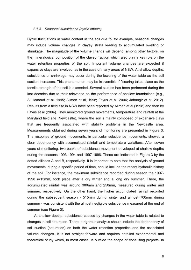
2.1.3. Seasonal subsidence (cyclic effects)
Cyclic fluctuations in water content in the soil due to, for example, seasonal changes
may induce volume changes in clayey strata leading to accumulated swelling or
shrinkage. The magnitude of the volume change will depend, among other factors, on
the mineralogical composition of the clayey fraction which also play a key role on the
water retention properties of the soil. Important volume changes are expected if
expansive clays are involved, as in the case of many areas of NSW. At shallow depths,
subsidence or shrinkage may occur during the lowering of the water table as the soil
suction increases. This phenomenon may be irreversible if fissuring takes place as the
tensile strength of the soil is exceeded. Several studies has been performed during the
last decades due to their relevance on the performance of shallow foundations (e.g.,
Al-Homoud et al, 1995; Allman et al, 1998; Fityus et al, 2004; Jahangir et al, 2012).
Results from a field site in NSW have been reported by Allman et al (1998) and then by
Fityus et al (2004). They monitored ground movements, temperature and rainfall at the
Maryland field site (Newcastle), where the soil is mainly composed of expansive clays
that are frequently associated with stability problems in the Newcastle area.
Measurements obtained during seven years of monitoring are presented in Figure 3.
The response of ground movements, in particular subsidence movements, showed a
clear dependency with accumulated rainfall and temperature variations. After seven
years of monitoring, two peaks of subsidence movement developed at shallow depths
during the seasons 1993-1994 and 1997-1998. These are indicated in Figure 3 by the
dotted ellipses A and B, respectively. It is important to note that the analysis of ground
movements, during a specific period of time, should include the recent hydraulic history
of the soil. For instance, the maximum subsidence recorded during season the 1997-
1998 (≈15mm) took place after a dry winter and a long dry summer. There, the
accumulated rainfall was around 380mm and 250mm, measured during winter and
summer, respectively. On the other hand, the higher accumulated rainfall recorded
during the subsequent season - 515mm during winter and almost 700mm during
summer - was consistent with the almost negligible subsidence measured at the end of
summer (see Figure 3).
At shallow depths, subsidence caused by changes in the water table is related to
changes in soil saturation. There, a rigorous analysis should include the dependency of
soil suction (saturation) on both the water retention properties and the associated
volume changes. It is not straight forward and requires detailed experimental and
theoretical study which, in most cases, is outside the scope of consulting projects. In

9
this particular field, important advances have been made by the Geotechnical Group at
The University of Newcastle Australia during last decade (see e.g., Sheng et al,
2003a,b; Fityus et al, 2004; Sheng et al, 2004; Buzzi et al, 2008; Sheng et al, 2008;
Buzzi et al, 2009; Zhou et al, 2012a,b,c).
Figure 3.Data from Maryland field site, NSW, registered between 1993 and 2000. (a)
Temperature (b) ground movements, (c) monthly rainfall (from Fityus et al, 2004)
2.2. Subsidence by anthropic factors
Subsidence may also occur as a result of various human activities. The main causes
related to engineering works can be summarized as follows:
Excavations: tied-back excavations, tunnelling, mining, etc.
Withdrawal of ground fluids: geothermal fluid extraction, water, oil and gas
production.
Indirect factors: induced sinkholes by mining activities, leaks of water in
underground pipes, induced earthquakes by mining activities, induced
compaction by changes in the hydraulic regime, due to mining or withdrawal of
pore fluid in underlying strata.
2.2.1. Excavation related (instantaneous or time-dependent)
A B

10
Any type of excavation causes ground movements. Their magnitude will depend on the
soil/rock properties as well as on the stress path applied. In most cases, ground
movements display some qualitative similarities, irrespective of the excavation method.
Ground settlements or subsidence are always accompanied by lateral movements.
Profiles of the ground movements, in a direction orthogonal to the excavation front,
tend to display some degree of symmetry. Finno & Roboski (2005) studied the three-
dimensional ground movements caused by a 12.8m deep tied-back excavation through
a mixed soil profile in Chicago (USA). The soil profile ranged from granular soils (z<5m)
to soft to medium stiff clays. The excavation was supported by a sheet pile wall and
three levels of tie-backs. Of particular interest was the quantification of both the vertical
and horizontal displacements caused by the excavation due to the potential damage on
neighboring buildings. Figure 4a shows the construction stages and the vertical
movements measured at the West Wall of the excavation. In addition, Figure 4(b)
compares the maximum vertical settlements and horizontal displacements measured at
different excavation stages. Maximum vertical movements of around 70mm were
recorded. Vertical settlements were higher than the horizontal displacements until
Stage 4. This ratio, however, decreased to around 0.80 in Stage 6. Finno & Roboski
attributed this behaviour to the volumetric response of the granular soils which
experienced compression at the initial stages of the excavation, but then dilated as the
ground movements become larger.
Different excavation methods cause different ground movements in a soil/rock
mass. In tunnelling, for instance, different excavation methods have been employed in
the past, depending the soil type and geological-geotechnical conditions. The tunnel
geometry plays a key role in both the short-term and long-term ground movements.
Traditional excavation methods for tunnelling in soils and rocks (e.g., cut-and-cover,
New Austrian Tunnelling Method, NATM) create a non-circular cavity in which stress
concentrations at the tunnel wall may cause stability problems. This problem is
overcome in new tunnelling techniques (Tunnelling Boring Machine: TBM, Earth
Pressure Balance: EPB) where the circular geometry minimizes the stress
concentration around the tunnel wall. In both cases, stability of the tunnel front is a key
concern, especially for shallow tunnels. Face stability analysis provides the most
probable failure mechanism, as well as the parameters that must be taken into
consideration when predicting the ground movements caused by tunnelling (ITA-
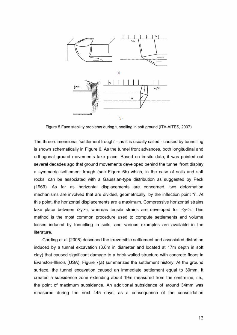
AITES, 2007). Two main collapse mechanisms may take place (see Figure 5). Large
volumes of soil are involved in front stability problems for clays. There, a sinkhole with

11
a width larger than one tunnel diameter may be formed (see Figure 5a). On the other
hand, chimneys are the common collapse mechanism in cohesionless soils (see Figure
5b).
Figure 4.Excavation of a tied-back in Chicago. (a) Excavation stages and vertical movements.
(b) Maximum vertical and horizontal movements (Finno & Roboski, 2005)
12
Figure 5.Face stability problems during tunnelling in soft ground (ITA-AITES, 2007)
The three-dimensional ‘settlement trough’ – as it is usually called - caused by tunnelling
is shown schematically in Figure 6. As the tunnel front advances, both longitudinal and
orthogonal ground movements take place. Based on in-situ data, it was pointed out
several decades ago that ground movements developed behind the tunnel front display
a symmetric settlement trough (see Figure 6b) which, in the case of soils and soft
rocks, can be associated with a Gaussian-type distribution as suggested by Peck
(1969). As far as horizontal displacements are concerned, two deformation
mechanisms are involved that are divided, geometrically, by the inflection point “i”. At
this point, the horizontal displacements are a maximum. Compressive horizontal strains
take place between i>y>-i, whereas tensile strains are developed for i<y<-i. This
method is the most common procedure used to compute settlements and volume
losses induced by tunnelling in soils, and various examples are available in the
literature.
Cording et al (2008) described the irreversible settlement and associated distortion
induced by a tunnel excavation (3.6m in diameter and located at 17m depth in soft
clay) that caused significant damage to a brick-walled structure with concrete floors in
Evanston-Illinois (USA). Figure 7(a) summarizes the settlement history. At the ground
surface, the tunnel excavation caused an immediate settlement equal to 30mm. It
created a subsidence zone extending about 19m measured from the centreline, i.e.,
the point of maximum subsidence. An additional subsidence of around 34mm was
measured during the next 445 days, as a consequence of the consolidation

13
experienced by the clay (see Figure 7a). The consolidation process experienced by the
clay is characterised by the volume change zone around the tunnel (the ellipse). The
extent of the subsidence zone increased up to 23m due to the long-term subsidence.
The South Wing of the building under consideration was located in the tension zone of
the settlement trough (Figure 7b). The measured vertical building displacement at the
South bearing wall was equal to 30mm, whereas the lateral ground displacement at the
edge of the building was computed to be 29mm. This caused diagonal shear cracks at
ground level but also above the windows close to the South wall. The maximum
opening of cracks observed was around 17mm, whereas the South and Central Wings
separated by around 5mm (see Figure 7b).
Figure 6.Tunnelling in soils. (a) Settlement trough (b) vertical and horizontal
movements
Figure 7.Consequences of tunnelling on buildings in Evanston. (a) Settlement trough. (b)
Damage on a neighbour building (Cording et al, 2008).
2.2.2. Mining subsidence (instantaneous or time-dependent)
Another excavation process causing important subsidence problems is due to mining
activities, e.g., longwall or room and pillar methods. This is of major interest in Australia

14
due to our long history of large-scale coal mining. Longwall coal mining involves cutting
panels around 150-400m wide, 1000-4000m long and 2-5m thick. The roof of the
excavation front is temporarily supported but is then allowed to collapse causing
subsidence. The coal that is allowed to collapse once the temporary support is
removed is defined as the goaf. Longwall mining operations are defined by the
extraction width, the panel length and the pillar width. All these affect the mine
subsidence, as the particular geological and geomechanical properties of the overlying
strata. The mechanisms of subsidence in longwall mining show some similarities with
those described previously for tunnelling, though the overburden is normally much
thicker. Some authors have described the “general scenario” for subsidence in longwall
mining (e.g., Bai & Kendorski, 1995; Holla & Barclay, 2000) (see Figure 8a).
Subsidence in longwall mining involves the development of a fully damaged zone
above the excavation width. Larger values of permeability are expected there due to
the high degree of fracturing. The thickness of the damaged zone may range between
10m to 20m (Seedsman Geotechnics Pty Ltd, 2012). The disturbed zone, i.e. the
soil/rock mass directly involved in the subsidence phenomenon, includes a thick layer -
6 to 30 times the excavated thickness according to Bai & Kendorski (1995) - overlying
the damage area. The points of maximum distortion - indicated by a dashed line in
Figure 8 - define the boundaries of the disturbed area. Small deformations, mainly in
the horizontal direction, take places in materials beside the disturbed zone so that
surface subsidence is caused by compaction of the shallow strata overlying the
disturbed zone. Dilation may also occur in intermediate strata (see, Bai & Kendorski,
1995) as a consequence of the large downward movement of the disturbed area,
compared with the small compaction of the underlying strata. As observed in Figure
8(b), a similar settlement trough or settlement bowl (as described previously in Figure
6b) is caused by subsidence in longwall mining. The extent of the subsidence, defined
by the angle of draw, is delimited by a minimum vertical subsidence of 20mm (not zero
as indicated in Figure 8a).
Seedsman Geotechnics Pty Ltd (2012) discuss the additional factors causing
subsidence in longwall operations which can be summarized as follows:
The presence of adjacent panels: for shallow panels subsidence is the sum of the
subsidence of independent panels; for deeper longwall panels subsidence is
controlled by the response of the chain pillars.
15
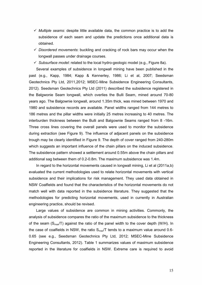
Multiple seams: despite little available data, the common practice is to add the
subsidence of each seam and update the predictions once additional data is
obtained.
Disordered movements: buckling and cracking of rock bars may occur when the
longwall passes under drainage courses.
Subsurface model: related to the local hydro-geologic model (e.g., Figure 8a).
Several examples of subsidence in longwall mining have been published in the
past (e.g., Kapp, 1984; Kapp & Kennerley, 1986; Li et al, 2007; Seedsman
Geotechnics Pty Ltd, 2011,2012; MSEC-Mine Subsidence Engineering Consultants,
2012). Seedsman Geotechnics Pty Ltd (2011) described the subsidence registered in
the Balgwonie Seam longwall, which overlies the Bulli Seam, mined around 70-80
years ago. The Balgownie longwall, around 1.35m thick, was mined between 1970 and
1980 and subsidence records are available. Panel widths ranged from 144 metres to
186 metres and the pillar widths were initially 25 metres increasing to 40 metres. The
interburden thickness between the Bulli and Balgownie Seams ranged from 8 -16m.
Three cross lines covering the overall panels were used to monitor the subsidence
during extraction (see Figure 9). The influence of adjacent panels on the subsidence
trough may be clearly identified in Figure 9. The depth of cover ranged from 240-280m
which suggests an important influence of the chain pillars on the induced subsidence.
The subsidence pattern showed a settlement around 0.55m above the chain pillars and
additional sag between them of 0.2-0.8m. The maximum subsidence was 1.4m.
In regard to the horizontal movements caused in longwall mining, Li et al (2011a,b)
evaluated the current methodologies used to relate horizontal movements with vertical
subsidence and their implications for risk management. They used data obtained in
NSW Coalfields and found that the characteristics of the horizontal movements do not
match well with data reported in the subsidence literature. They suggested that the
methodologies for predicting horizontal movements, used in currently in Australian
engineering practice, should be revised.
Large values of subsidence are common in mining activities. Commonly, the
analysis of subsidence compares the ratio of the maximum subsidence to the thickness
of the seam (Smax/T) against the ratio of the panel width to the cover depth (W/H). In
the case of coalfields in NSW, the ratio Smax/T tends to a maximum value around 0.6-
0.65 (see e.g., Seedsman Geotechnics Pty Ltd, 2012; MSEC-Mine Subsidence
Engineering Consultants, 2012). Table 1 summarizes values of maximum subsidence
reported in the literature for coalfields in NSW. Extreme care is required to avoid

16
damaging effects on urban settings and neighbouring structures (e.g., dams, highways,
bridges, underground pipes). Due to the complexity of each scenario, the impact of
subsidence is commonly evaluated individually.
Figure 8.Subsidence in longwall mining.(a) Subsidence model (Hall & Barclay, 2000). (b)
Development of vertical and horizontal displacements
Table 1.Some published data of maximum subsidence in NSW coalfields
Location Panel T
(m)
W
(m)
H
(m)
Smax
(m)
Source
Newstan
Colliery
LW 6 3.4 155 60 2.03 Holla &
Thompson (1992) LW 8 3.2 210 75 3.03
Liddell
Colliery
LW 1 2.4 180 160 1.55
Li et al (2007) LW 3 2.0 180 200 2.10
Cumnock
Colliery
LW 17 2.2 210 90 1.72
LW 3 2.5 205 133 1.25

17
Figure 9.Subsidence registered in Balgownie seam longwall (from Seedsman Geotechnics Pty Ltd, 2011)
2.2.3. Subsurface erosion and karst collapse (instantaneous and time-dependent)
Another type of subsidence related to mining activities is the creation of sinkholes or
caverns, mainly due to shallow overburden, poor mechanical properties of the
overburden material, geological conditions (such as discontinuities), and the presence
of soluble rocks. This problem is usually studied as a face stability problem as
previously described for tunnelling. Some examples of sinkhole formations due to
mining activities have been discussed by Singh & Dhar (1997).
2.2.4. Withdrawal of ground pore fluid (time-dependent) One of the most common activities causing subsidence is related to the withdrawal of
ground fluids such as geothermal water or steam, ground water, and oil and gas. Each
of these has caused a maximum subsidence of the same order or magnitude (Poland,
1984). In general terms, subsidence occurs as a result of two mechanisms during
ground fluid withdrawal: (i) local compaction due to the reduction of the pore pressure
that increases the effective stress according to consolidation theory, and (ii) lateral
shrinkage of strata where the water table was lowered. The subsidence bowl tends to

18
be approximately symmetric, even if the compacted volume is not. Due to the complex
geological profiles found in nature, the withdrawal of ground fluids does not only affect
the specific strata under consideration, but also layers located above and below. Thus,
the subsidence bowl is a result of the superposition of subsidence from each
compacted strata. Although compaction and subsidence are related, it is not easy to
observe compaction of an underground reservoir. Surface subsidence, however, may
be detected easily. In fact, subsidence has been recognized as the first indicator of
compaction over hydrocarbon fields since the first case studies were published (e.g.,
Pratt & Johnson, 1926).
Doornhof et al (2006) divided the formations involved in subsidence as follows: (i)
compacting volume, (ii) overburden, (iii) sideburden – materials laterally connected to
the compacting formation, and (iv) underburden – materials beneath the compacting
formation and the sideburden. The last two terms are frequently taken into account in
geomechanical analysis. The compacting volume does not only include the
hydrocarbon-bearing formation, but also the aquifers above or below that can be
compacted and act as drains. On the other hand, the sideburden material does not
experience compaction and, on the contrary, it helps to sustain some of the overburden
weight that had been supported by the compaction formation via arching effect. The
importance of the arching effect will depend on the properties of both the overburden
and sideburden materials, the lateral extent of the compacting zone, and the amount of
compaction (Doornhof et al, 2006). Some examples are described below, which
comment on the particular aspects involved with the removal of ground water and oil
and gas, respectively.
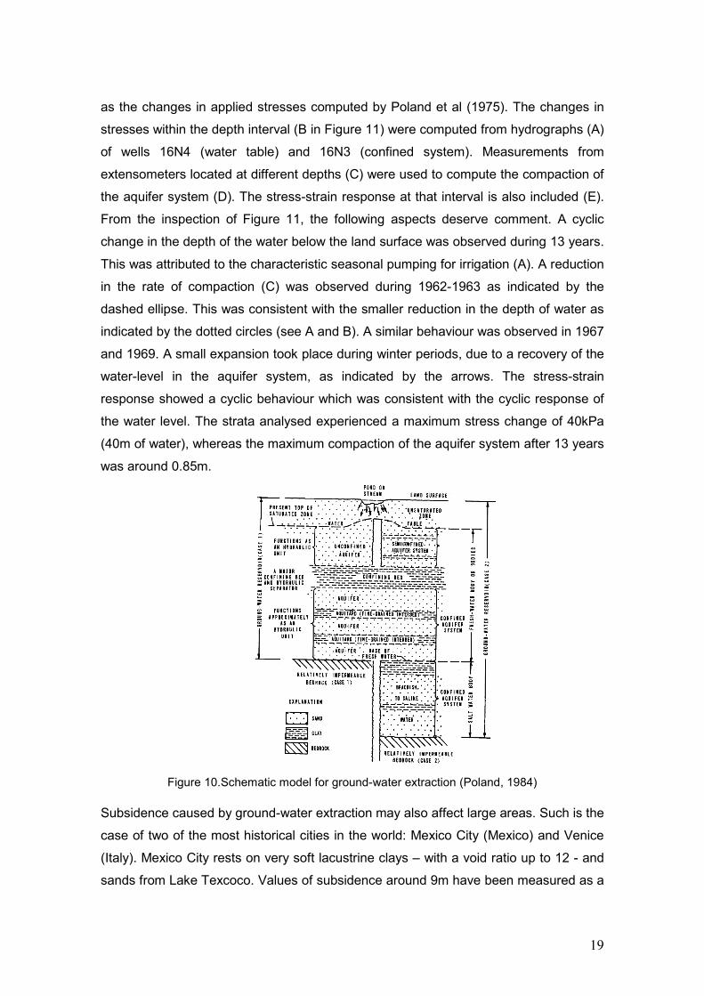
Figure 10 shows the general scenario that can be found during ground-water
extraction (Poland, 1984). Two cases are analysed in this figure. Case 1 (left) includes
only one confined aquifer system whereas in Case 2 (right) there are two. Confined
beds and aquitards (fine-grained compressible interbeds) are also included in both
cases to describe the most general cases encountered in practice. Aquitards play a key
role in the subsidence potential due to their high susceptibility to compaction (because
of its fine-grained nature) compared to the sand or gravel composing the aquifer during
an increase in stress. Based on 13 years of continuous monitoring, Poland et al (1975)
published the response of an aquifer system (101m thickness) at the Pixley site in the
southern part of the San Joaquin Valley-California (USA) (see also Poland, 1984).
There, around 60 aquitards with different thickness ranging from 0.6 to 15m has been
reported. Figure 11 shows the monitored data – water level and compaction - as well
19
as the changes in applied stresses computed by Poland et al (1975). The changes in
stresses within the depth interval (B in Figure 11) were computed from hydrographs (A)
of wells 16N4 (water table) and 16N3 (confined system). Measurements from
extensometers located at different depths (C) were used to compute the compaction of
the aquifer system (D). The stress-strain response at that interval is also included (E).
From the inspection of Figure 11, the following aspects deserve comment. A cyclic
change in the depth of the water below the land surface was observed during 13 years.
This was attributed to the characteristic seasonal pumping for irrigation (A). A reduction
in the rate of compaction (C) was observed during 1962-1963 as indicated by the
dashed ellipse. This was consistent with the smaller reduction in the depth of water as
indicated by the dotted circles (see A and B). A similar behaviour was observed in 1967
and 1969. A small expansion took place during winter periods, due to a recovery of the
water-level in the aquifer system, as indicated by the arrows. The stress-strain
response showed a cyclic behaviour which was consistent with the cyclic response of
the water level. The strata analysed experienced a maximum stress change of 40kPa
(40m of water), whereas the maximum compaction of the aquifer system after 13 years
was around 0.85m.
Figure 10.Schematic model for ground-water extraction (Poland, 1984)
Subsidence caused by ground-water extraction may also affect large areas. Such is the
case of two of the most historical cities in the world: Mexico City (Mexico) and Venice
(Italy). Mexico City rests on very soft lacustrine clays – with a void ratio up to 12 - and
sands from Lake Texcoco. Values of subsidence around 9m have been measured as a

20
consequence mainly of the compaction of two silty clay strata (25-30m and 5-10m
thick) located in the top 50m below the ground surface. Figueroa-Vega (1984)
established that about 75% of the overall subsidence was caused by the compaction of
the shallow clayey strata and the remainder subsidence was due to compression of the
underlying aquifer which are hundreds of meters thick. Venice, on the other hand, has
suffered major subsidence since the last century due mainly to two causes: (i) ground-
water extraction that increased dramatically after World War II due to the increase in
population, and (ii) natural gas extraction in a zone across the lagoon. This caused an
increase in the rate of subsidence of up to 1.4-1.7cm/yr, measured between 1968-1969
(Brighenti et al, 1995). After a heavy flooding event in 1966, the extraction of water and
gas was essentially halted to control subsidence. This lead to a small rebound of the
surface once the aquifer level rose. Despite this, the city is still experiencing
subsidence, although under a lower rate. As for subsidence caused by geothermal
ground fluid withdrawal, the reader is referred to the review published by Narasimham
& Goyal (1984). There, subsidence is attributed to the volume changes during
depletion of geothermal fluid in addition to geothermal contraction.

21
Figure 11.Ground water extraction in San Joaquin Valley. (a) Hygrographs. (b) Changes in
applied stresses. (c) Compaction in different levels. (d) Compaction in 131-232m depth interval. (e) Stress changes vs strain (from Poland et al, 1975)
In general terms, oil and gas extraction follow the same physical mechanisms
controlling ground-water and geothermal fluid extraction: oil/gas withdrawal decreases
the pore pressure which causes compaction and finally surface subsidence. The chief
difference is that oil/gas reservoirs generally do not show the seasonal depletion-
refilling process as observed in aquifers (see A in Figure 11). Some of the most
Expansion
Change in the rate of compaction
22
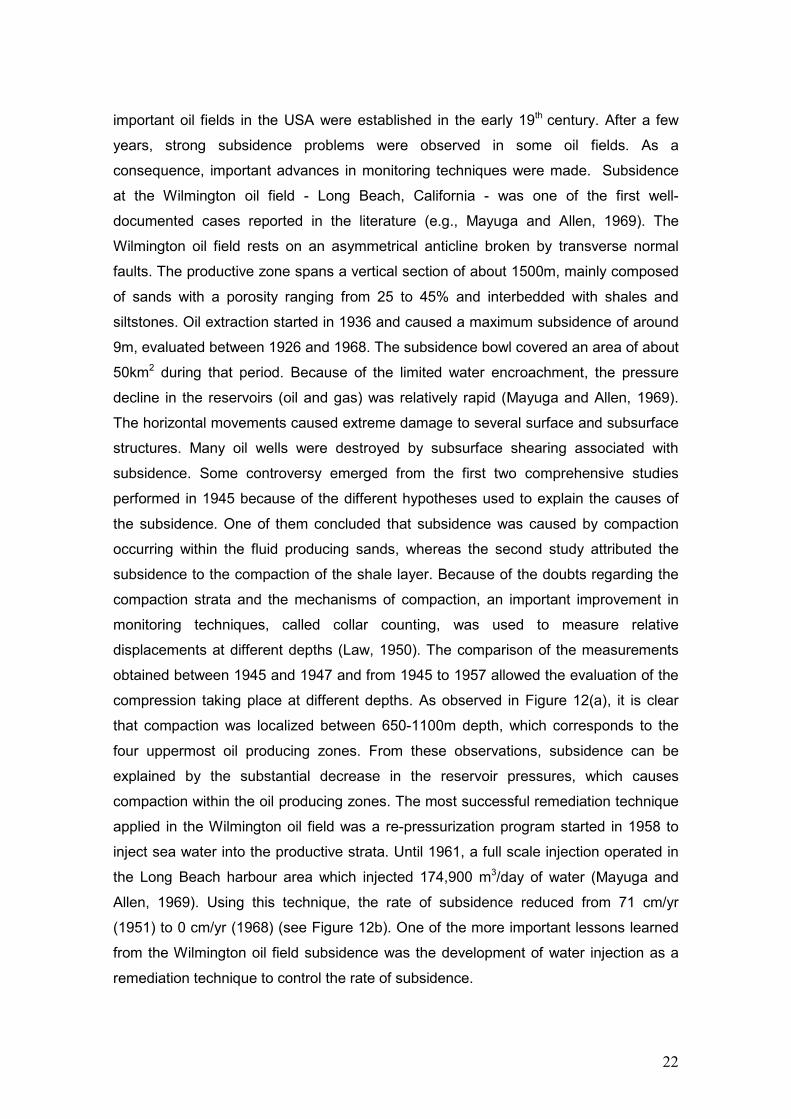
important oil fields in the USA were established in the early 19th century. After a few
years, strong subsidence problems were observed in some oil fields. As a
consequence, important advances in monitoring techniques were made. Subsidence
at the Wilmington oil field - Long Beach, California - was one of the first well-
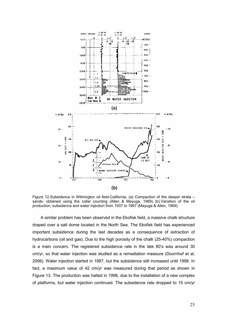
documented cases reported in the literature (e.g., Mayuga and Allen, 1969). The
Wilmington oil field rests on an asymmetrical anticline broken by transverse normal
faults. The productive zone spans a vertical section of about 1500m, mainly composed
of sands with a porosity ranging from 25 to 45% and interbedded with shales and
siltstones. Oil extraction started in 1936 and caused a maximum subsidence of around
9m, evaluated between 1926 and 1968. The subsidence bowl covered an area of about
50km2 during that period. Because of the limited water encroachment, the pressure
decline in the reservoirs (oil and gas) was relatively rapid (Mayuga and Allen, 1969).
The horizontal movements caused extreme damage to several surface and subsurface
structures. Many oil wells were destroyed by subsurface shearing associated with
subsidence. Some controversy emerged from the first two comprehensive studies
performed in 1945 because of the different hypotheses used to explain the causes of
the subsidence. One of them concluded that subsidence was caused by compaction
occurring within the fluid producing sands, whereas the second study attributed the
subsidence to the compaction of the shale layer. Because of the doubts regarding the
compaction strata and the mechanisms of compaction, an important improvement in
monitoring techniques, called collar counting, was used to measure relative
displacements at different depths (Law, 1950). The comparison of the measurements
obtained between 1945 and 1947 and from 1945 to 1957 allowed the evaluation of the
compression taking place at different depths. As observed in Figure 12(a), it is clear
that compaction was localized between 650-1100m depth, which corresponds to the
four uppermost oil producing zones. From these observations, subsidence can be
explained by the substantial decrease in the reservoir pressures, which causes
compaction within the oil producing zones. The most successful remediation technique
applied in the Wilmington oil field was a re-pressurization program started in 1958 to
inject sea water into the productive strata. Until 1961, a full scale injection operated in
the Long Beach harbour area which injected 174,900 m3/day of water (Mayuga and
Allen, 1969). Using this technique, the rate of subsidence reduced from 71 cm/yr
(1951) to 0 cm/yr (1968) (see Figure 12b). One of the more important lessons learned
from the Wilmington oil field subsidence was the development of water injection as a
remediation technique to control the rate of subsidence.
23
Figure 12.Subsidence in Wilmington oil field-California. (a) Compaction of the deeper strata –sands- obtained using the collar counting (Allen & Mayuga, 1969) (b).Variation of the oil production, subsidence and water injection from 1937 to 1967 (Mayuga & Allen, 1969)
A similar problem has been observed in the Ekofisk field, a massive chalk structure
draped over a salt dome located in the North Sea. The Ekofisk field has experienced
important subsidence during the last decades as a consequence of extraction of
hydrocarbons (oil and gas). Due to the high porosity of the chalk (25-40%) compaction
is a main concern. The registered subsidence rate in the late 80’s was around 30
cm/yr, so that water injection was studied as a remediation measure (Doornhof et al,
2006). Water injection started in 1987, but the subsidence still increased until 1998. In
fact, a maximum value of 42 cm/yr was measured during that period as shown in
Figure 13. The production was halted in 1998, due to the installation of a new complex
of platforms, but water injection continued. The subsidence rate dropped to 15 cm/yr
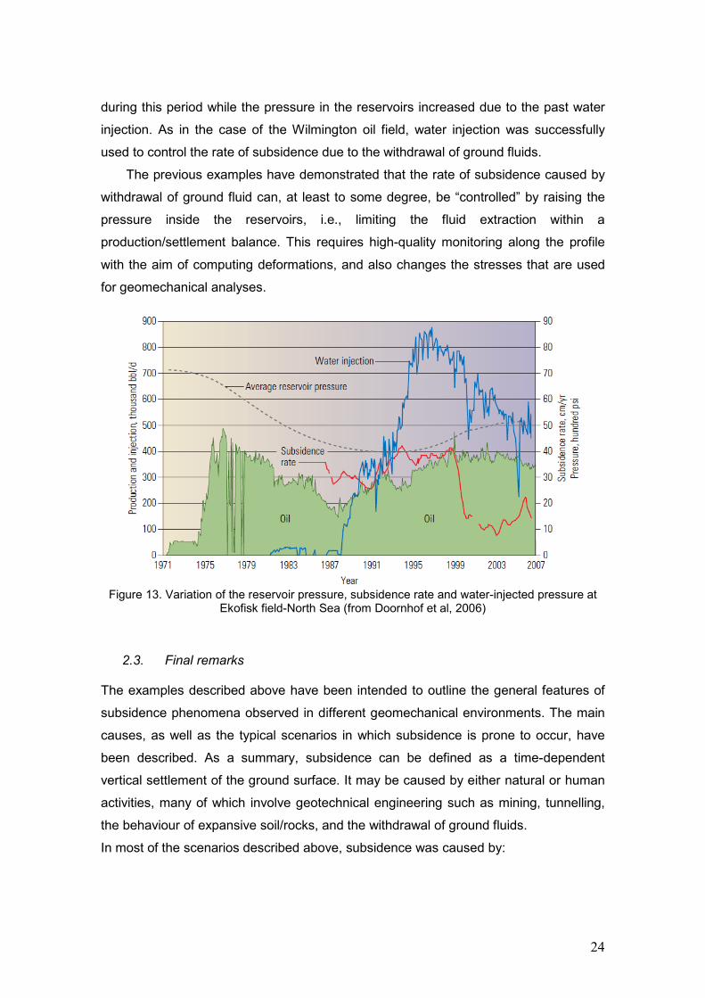
24
during this period while the pressure in the reservoirs increased due to the past water
injection. As in the case of the Wilmington oil field, water injection was successfully
used to control the rate of subsidence due to the withdrawal of ground fluids.
The previous examples have demonstrated that the rate of subsidence caused by
withdrawal of ground fluid can, at least to some degree, be “controlled” by raising the
pressure inside the reservoirs, i.e., limiting the fluid extraction within a
production/settlement balance. This requires high-quality monitoring along the profile
with the aim of computing deformations, and also changes the stresses that are used
for geomechanical analyses.
Figure 13. Variation of the reservoir pressure, subsidence rate and water-injected pressure at
Ekofisk field-North Sea (from Doornhof et al, 2006)
2.3. Final remarks
The examples described above have been intended to outline the general features of
subsidence phenomena observed in different geomechanical environments. The main
causes, as well as the typical scenarios in which subsidence is prone to occur, have
been described. As a summary, subsidence can be defined as a time-dependent
vertical settlement of the ground surface. It may be caused by either natural or human
activities, many of which involve geotechnical engineering such as mining, tunnelling,
the behaviour of expansive soil/rocks, and the withdrawal of ground fluids.
In most of the scenarios described above, subsidence was caused by:
25
• Loss of a volume of soil/rock and associated consolidation due to tunnelling, or
mining activities.
• Compaction of some strata due to the dissipation of pore pressure, which is
often associated with the withdrawal of ground fluids.
• Collapse of a soil/rock mass due to tunnelling or the formation of sinkholes.
The analysis of subsidence shows some similarities in these scenarios. Consolidation
theory, as used in soil mechanics, is employed to quantify the compaction of strata due
to changes in water table and the withdrawal of ground fluid, but is also used to predict
the settlement of clayey layers induced by other processes. Although Coal Seam Gas
(CSG) production involves the same physical processes described above, and is now
discussed in the following sections.

26
3. Coal seam gas (CGS) extraction Coal seam gas (CSG) is a ‘natural gas’ comprised of around 97% methane. It is formed
from the compression of organic matter under pressure, thermal changes (thermogenic
processes) and also, although to a lesser degree, by biological reactions. Coal seam
gas is usually referred to as ‘unconventional’ gas because it occurs in unconventional
deposits – coal beds - located typically at between 300-1000m depth (www.csiro.au).
For instance, in the Camden Gas Project in south-western Sydney, coal seams are
located at between 600-1000m depth. There, the two upper seams - Bulli and
Balgownie - are the major CSG targets.
Coal is a low porosity sedimentary rock composed of two constituents (see Figure
14): (i) the coal matrix, which displays a very low porosity, and (ii) a system of
orthogonal fractures (cleats) that divide the coal matrix into ‘blocks’. The fractured or
cleated nature, and the unique storage mechanism of methane through adsorption, are
the two distinguishing features that control the extraction process (taken here to include
both the exploration methods and subsurface operation in CSG production (Loftin,
2009)). Methane is adsorbed by the micro-pores within the coal matrix, at a near-liquid
state, due to the large internal surface area of the coal matrix. Methane is also stored
inside the cleats, although it represents only around 5-9% of the total volume in the
coal seam (Close, 1993). Due to the high efficiency of the adsorption mechanism,
methane extraction from coal is more complex compared with conventional gas
reservoirs. Methane adsorption is maintained by pressure, e.g. hydrostatic water
pressure. If the pressure decreases the methane is able to ‘de-sorb’ from the coal and
become mobile. The release of methane from the coal is analysed using the Langmuir
isotherm which is unique for each coal formation. The isotherm describes the gas
storage capacity (e.g., scf/ton) as a function of the pore fluid pressure (see Figure 15).
In other words, it represents the maximum storage capacity of a coal in a formation at
given pressure. Thus, coal is saturated if its current gas content is equal to the storage
capacity as described by points located on the isotherm. If the current gas content is
lower than the maximum storage capacity at a given pressure, the coal is under-
saturated and the current state locates below the isotherm. A coal seam may reduce its
gas content but remain saturated by following a path along the isotherm (path 1-2), as
could happen in a geological uplift. If the coal is reloaded, the released gas is not re-
stored (path 2-3) and the under-saturated state is maintained. At point 3 (see Figure
15) the coal contains less gas than could be expected under the current pressure. In

27
addition, methane will not be released until the pressure reduces and reaches the
isotherm. During this process, only water is extracted from the well (Loftin, 2009).
‘De-watering’ of the cleat system is the first stage of a gas extraction process. A
large volume of water is usually extracted to reduce the water pressure until the
methane is released from the coal matrix. Over time, gas production increases as the
cleat system is saturated with ‘de-sorbed’ gas, as in shown schematically in Figure 14.
The low gas rate observed during early extraction is contrary to the common
observation in conventional reservoirs, where high gas production rates are achieved
from the beginning of the extraction process. This behaviour adds another unique
feature to coal seam gas. Loftin (2009) remarked that both the water-filled cleat
system, as well as the shape of the isotherm curve, impacts on every aspect of the field
development (both subsurface and surface).
Figure 14.Movement of methane in coal (from Loftin, 2009).
Figure 15.Langmuir isotherm for coal (from Loftin, 2009).

28
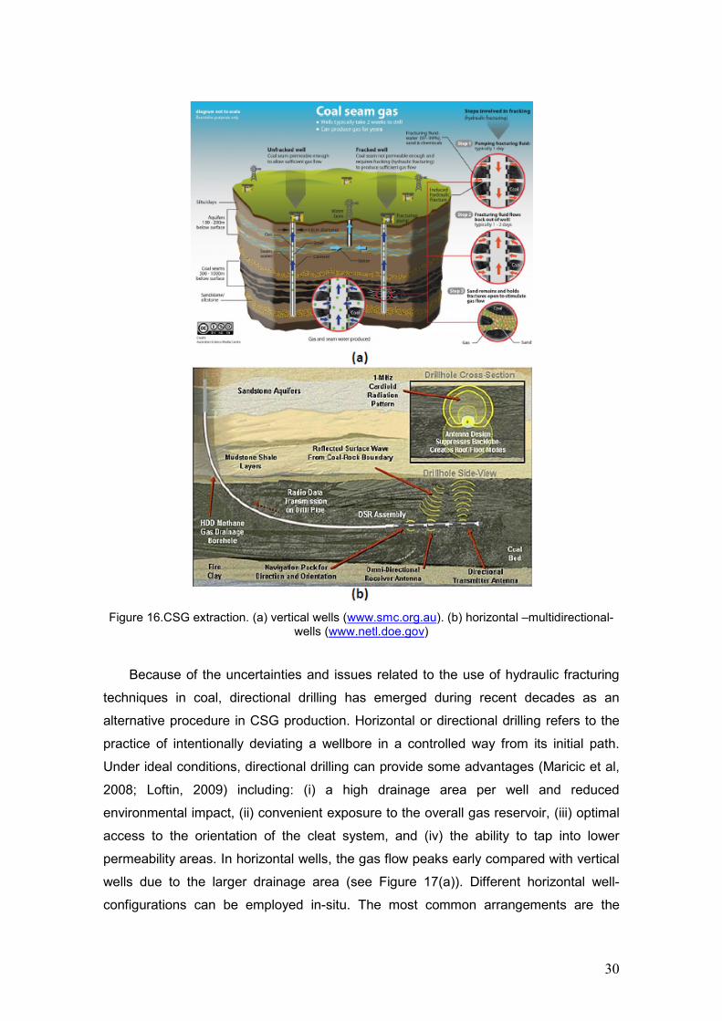
3.1. Extraction methods in Coal Seam Gas (CSG)
In CSG production, gas is extracted through wells drilled to pump out the ground water-
gas mixture. Due to the very low permeability of the coal matrix, non-conventional
drilling techniques are required to promote the creation of new pathways for gas
extraction. Two main configurations, involving two drilling techniques, are usually
employed in CSG production: (i) vertical wells (vertical drilling), and (ii) horizontal
boreholes (directional drilling) connected to a main vertical well.
Gas extraction from a single vertical well (see Figure 16(a)) is generally inefficient.
To achieve the desired production from vertical wells, many closely spaced wells are
required, but this is often uneconomic. For this reason, stimulation techniques are
required. Hydraulic fracturing or so-called “fracking” is frequently employed to increase
the permeability of the medium around the wells. Alternatively, the combination of a
vertical well with directional drilling techniques can be employed in CSG practice to
reduce the need for hydraulic fracturing (see Figure 14(b)), although in very low
porosity shale gas extraction, both horizontal drilling and fracturing are combined. A
mandatory requirement in all cases is the proper casing (insulation) of the vertical well
to avoid the contamination of aquifers in strata overlying and underlying the coal seam.
Depending on the permeability of the coal and the drilling method employed, hydraulic
fracturing requirements may be minimal or massive.
Hydraulic fracturing involves the injection of fluid under pressure
(water+sand+proppants) into the well to enhance the fracturing pattern of the coal
seam (Figure 16a). The fluid pressure is increased quickly, reaching values above the
minor in-situ stress and tensile strength of the coal. This induces the propagation of
cleats but also creates new fractures. According to linear fracture mechanics, pre-
existing fractures or cleats propagate until the stress-intensity at the fracture tip is lower
than a critical stress-intensity of the rock (e.g., Savalli & Engelder, 2005). Once the
injection of fluid has finished, the ground pore fluid is pumped out to the surface. During
this process, methane is released from the coal micro-pores and flows through the
cleats, as the pressure decreases according to the isotherm. The initiation and
propagation of hydraulic fractures are, however, not well understood from the
standpoint of physics and mechanics. In fact, highly experienced practitioners
recognize that the optimization of the hydraulic fracturing process in coal seams is, in
most cases, a trial-and-error exercise (e.g., Loftin, 2009). Two main factors are
considered to influence the fracture behaviour in CSG production. First, hydraulic
fractures may extend far from the target formation into overlying and underlying strata.

29
Secondly, fractures may connect with natural fracture systems and permeable
formations, facilitating the unintended movement of fracturing fluids. During the
hydraulic fracturing process, the propagation of fractures is affected by the following
site-specific factors (Ketelaar, 2009):
Properties of the coal seam and surrounding geologic formations: horizontal
fractures more commonly occur at shallow depths as they propagate
perpendicular to the direction of the minor stress. Vertical fractures are
expected to occur in deeper coal seams.
Natural fracture (cleat) systems: hydraulic fracturing enhances natural cleating.
The preferential fracture direction of the cleats is exploited to some degree.
In-situ stress state and stress changes: the magnitude and direction of the
principal stresses control the pressure required and the propagation of
fractures.
Operator’s influence: fracture dimensions will be affected by the different
approaches adopted by different drilling operators.
Despite being common practice, hydraulic fracturing techniques in CSG production are
by no means standardized. Each coal seam is different so that the effects of using
different fracturing techniques cannot be quantified easily. The outcomes of fracturing
processes depend to a high degree on the expertise and experience of the operator
who, in some cases, may have a financial incentive to keep the hydraulically-induced
fracture within the target coal zone (Ketelaar, 2009).
30
Figure 16.CSG extraction. (a) vertical wells (www.smc.org.au). (b) horizontal –multidirectional-
wells (www.netl.doe.gov)
Because of the uncertainties and issues related to the use of hydraulic fracturing
techniques in coal, directional drilling has emerged during recent decades as an
alternative procedure in CSG production. Horizontal or directional drilling refers to the
practice of intentionally deviating a wellbore in a controlled way from its initial path.
Under ideal conditions, directional drilling can provide some advantages (Maricic et al,
2008; Loftin, 2009) including: (i) a high drainage area per well and reduced
environmental impact, (ii) convenient exposure to the overall gas reservoir, (iii) optimal
access to the orientation of the cleat system, and (iv) the ability to tap into lower
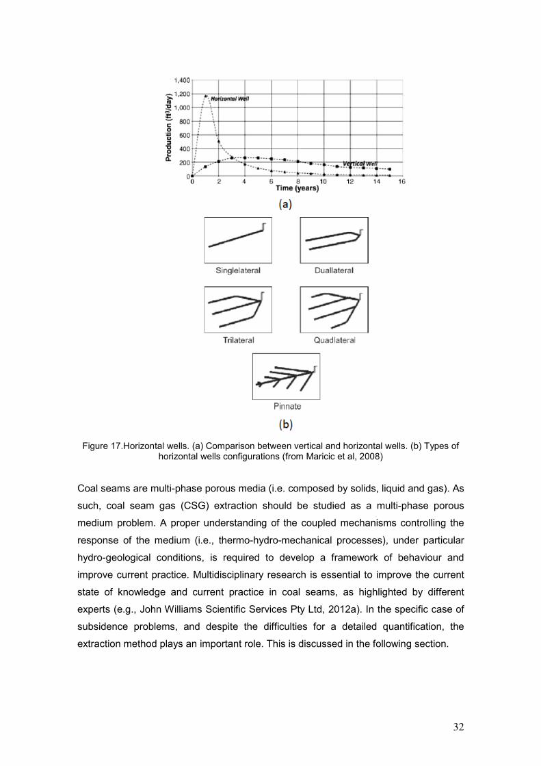
permeability areas. In horizontal wells, the gas flow peaks early compared with vertical
wells due to the larger drainage area (see Figure 17(a)). Different horizontal well-
configurations can be employed in-situ. The most common arrangements are the

31
single-lateral, dual-lateral, trilateral, quadrilateral, and fishbone (pinnate) configurations
as shown in Figure 17(b). In most cases, a single vertical well is used to pump out the
water-gas mixture. A parametric study performed by Maricic et al (2008) analyzed the
influence of well configuration, spacing between laterals (BBL), and length on the
efficiency of coal seam methane extraction. Using a specific set of reservoir properties,
they showed that a quadrilateral well configuration achieved the optimum production
rate. This result is in agreement with the experience of other authors, although some
problems related to wellbore collapse and de-watering of the laterals has also been
reported to occur (see e.g., Loftin, 2009).
The main problems reported with horizontal wells seem to occur at shallow depths
where high-angle directional wells are required. High-angle wells sometimes cause
several complications when crossing through naturally-cleated coal. The interaction
between the hole-angle, the well azimuth and the hydraulic fracture azimuth defines the
good or poor alignments in regard to the plane of hydraulic fracture (see Figure 18).
Poor alignment may lead to premature screen-out and ineffective flow recovery of the
fracturing fluid. In most vertical wells, in horizontal seams, good results are obtained
from hydraulic fracturing as the wellbore is (by default) typically aligned with the plane
of fracturing (Figure 18) since cleats are typically developed perpendicular to the coal
bed thickness. In directional wells, two additional factors have to be taken into
consideration: (i) the well azimuth and (ii) the azimuth of the face cleats. Satisfactory
results are obtained if the well azimuth tends to be parallel to the azimuth of the face
cleats. However, if the well azimuth deviates from the azimuth of the cleats by more
than about 10º, systematic problems may appear. Transverse fractures may form along
the wellbore. This may limit the propagation of the fractures in the well bore, if the
transverse fractures interfere with each other creating tortuous flow paths. An increase
in the hole-angle as well as the difference between azimuths will magnify the problems
discussed above (Loftin, 2009).
32
Figure 17.Horizontal wells. (a) Comparison between vertical and horizontal wells. (b) Types of
horizontal wells configurations (from Maricic et al, 2008)
Coal seams are multi-phase porous media (i.e. composed by solids, liquid and gas). As
such, coal seam gas (CSG) extraction should be studied as a multi-phase porous
medium problem. A proper understanding of the coupled mechanisms controlling the
response of the medium (i.e., thermo-hydro-mechanical processes), under particular
hydro-geological conditions, is required to develop a framework of behaviour and
improve current practice. Multidisciplinary research is essential to improve the current
state of knowledge and current practice in coal seams, as highlighted by different
experts (e.g., John Williams Scientific Services Pty Ltd, 2012a). In the specific case of
subsidence problems, and despite the difficulties for a detailed quantification, the
extraction method plays an important role. This is discussed in the following section.

33
Figure 18.Relationship between the drilling procedure and the characteristics of the coal seam
(from Loftin, 2009)
3.2. Subsidence associated with Coal Seam Gas production
The study of the subsidence caused by Coal Seam Gas (CSG) production is even
more complex than the subsidence associated with mining or civil engineering activity,
due to the special interrelationship between the different phases (gas, liquid and solid)
inside a naturally fractured system such as coal seam. Some of these couplings are not
well-understood. The main problem lies in the fact that the coal in each seam is
different and behaves according its own isotherm and the characteristics of its cleat
system (which is further modified during the ‘stimulation’ process). Even under the
guidance of a highly qualified operator, drilling and ‘stimulation’ processes induce a
certain level of disturbance, not only in the coal seam itself but also through the entire
geological profile. Under ideal conditions, if the disturbance is properly quantified,
which includes reliable prediction of stresses and fluid pressures in different strata, it
would be possible to analyse changes in the mechanical behaviour during gas
extraction with a high degree of confidence. In the particular case of subsidence
associated with gas extraction, the marketing requirements of high production rates
speeds up the compaction of geological strata, which may in turn cause unexpected
surface settlements.
34
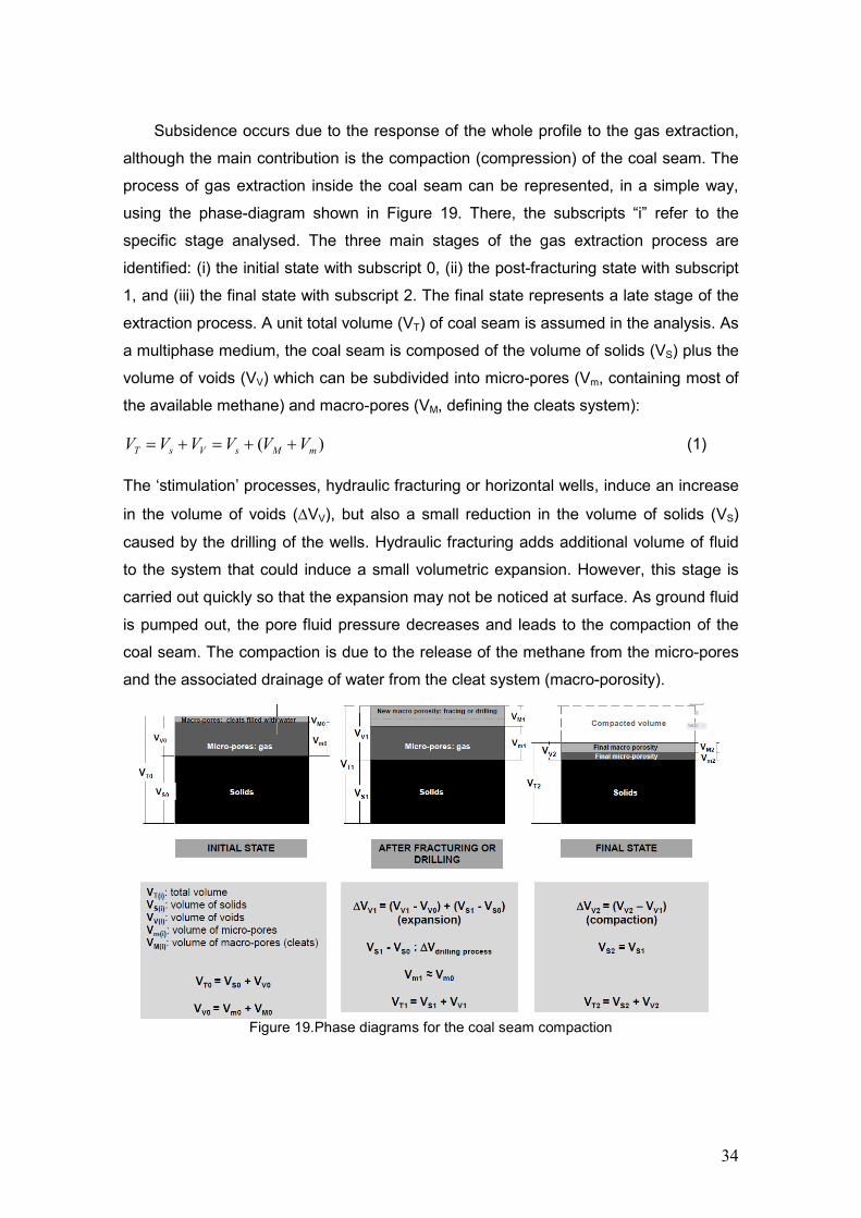
Subsidence occurs due to the response of the whole profile to the gas extraction,
although the main contribution is the compaction (compression) of the coal seam. The
process of gas extraction inside the coal seam can be represented, in a simple way,
using the phase-diagram shown in Figure 19. There, the subscripts “i” refer to the
specific stage analysed. The three main stages of the gas extraction process are
identified: (i) the initial state with subscript 0, (ii) the post-fracturing state with subscript
1, and (iii) the final state with subscript 2. The final state represents a late stage of the
extraction process. A unit total volume (VT) of coal seam is assumed in the analysis. As
a multiphase medium, the coal seam is composed of the volume of solids (VS) plus the
volume of voids (VV) which can be subdivided into micro-pores (Vm, containing most of
the available methane) and macro-pores (VM, defining the cleats system):
)( mMsVsT VVVVVV ++=+= (1)
The ‘stimulation’ processes, hydraulic fracturing or horizontal wells, induce an increase
in the volume of voids (∆VV), but also a small reduction in the volume of solids (VS)
caused by the drilling of the wells. Hydraulic fracturing adds additional volume of fluid
to the system that could induce a small volumetric expansion. However, this stage is
carried out quickly so that the expansion may not be noticed at surface. As ground fluid
is pumped out, the pore fluid pressure decreases and leads to the compaction of the
coal seam. The compaction is due to the release of the methane from the micro-pores
and the associated drainage of water from the cleat system (macro-porosity).
Figure 19.Phase diagrams for the coal seam compaction

35
As the external forces remain constant during gas production, the compaction of the
coal seam is due to the dissipation of the pore fluid pressure (∆ufluid). The factor that
plays a key role in the degree of compaction is the compressibility of the coal seam.
Figure 20 shows a schematic compression curve in the space of porosity vs effective
stress for a natural coal seam. λnat defines the compressibility index of the natural coal
seam developed along its geological history. As known in geomechanics, λnat remains
more or less constant, if the coal seam maintains a normally-consolidated state. Thus,
the point O defines the in-situ stress state at the time of development. Drilling and
‘stimulation’ procedures cause a small reduction in the effective stress, represented by
the path OA. If the disturbance induced during the ‘stimulation’ process is negligible,
the stress state should move along the compression curve for the natural coal until its
reaches the point B’ (path AOB’), as the pore fluid pressure dissipates. However, the
disturbance caused by fracturing allows the stress state to move along the path AB
that, as observed in Figure 20, displays a higher compressibility index, λfrac. A higher
compaction should be expected in this case. If the lateral dimension of the coal seam is
large compared to its thickness, the compaction is assumed to be mainly vertical and
the maximum compaction can be quantified from conventional consolidation theory
(Terzaghi, 1925) in terms of the compressibility modulus (mv=∆εv/∆p’; ∆εv→change in
vertical strain, ∆p’→change in effective stress), pressure change (∆ufluid) and reservoir
thickness (H): Smax=mv.∆ufluid.H. The compressibility of the coal seam in the horizontal
direction depends also on Poisson’s ratio, ν, which defines the ratio between the
horizontal and vertical strains. The magnitude of ν and mv in the coal seam are
influenced by the stimulation process, in particular by their effectiveness. There is a
direct relationship between commercial requirements for high production rates (intense
fracturing and increasing mv) and subsidence issues. In this sense, a rigorous control
of the stimulation processes and gas production, including the continuous monitoring of
pressures and relative displacements along the entire profile, will have at least two
important benefits: (i) a better estimation of compressibility mv and Poisson’s ratio of
different strata, and (ii) a proper estimation of the induced compaction.

36
Figure 20. Schematic view of the coal seam compaction
Surface subsidence can also result from indirect subsidence: the compaction of
underlying and overlying strata. Additional compaction will take place if the hydraulic
regime within the entire profile is modified, e.g. in the aquifer system. Thus, the
maximum surface subsidence can be estimated as the compaction of each stratum as
follows:
∑=
−− ⋅∆⋅=+=n
iiifluidivstrataotherindirectseamcoaldirect HumSSS
1)()()()()(max (2)
For instance, Figure 21 shows the geological profiles at the Camden Gas Project in
south-western Sydney, where the coal seam targets for CSG production – Bulli and
Balgownie - are located at a depth of around 770m. In these cases, the maximum
37
subsidence should be the result of compaction of the two coal seams plus the
additional compaction due to the ‘de-watering’ caused in the overlying strata (such as
the claystone located at the top of the Bulli seam).
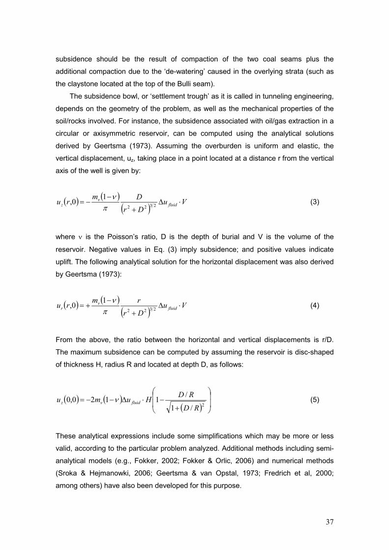
The subsidence bowl, or ‘settlement trough’ as it is called in tunneling engineering,
depends on the geometry of the problem, as well as the mechanical properties of the
soil/rocks involved. For instance, the subsidence associated with oil/gas extraction in a
circular or axisymmetric reservoir, can be computed using the analytical solutions
derived by Geertsma (1973). Assuming the overburden is uniform and elastic, the
vertical displacement, uz, taking place in a point located at a distance r from the vertical
axis of the well is given by:
( ) ( )( )
VuDrDmru fluid
vz ⋅∆
+
−−= 2322
10,π
ν (3)
where ν is the Poisson’s ratio, D is the depth of burial and V is the volume of the
reservoir. Negative values in Eq. (3) imply subsidence; and positive values indicate
uplift. The following analytical solution for the horizontal displacement was also derived
by Geertsma (1973):
( ) ( )( )
VuDrrmru fluid
vr ⋅∆
+
−+= 2322
10,π
ν (4)
From the above, the ratio between the horizontal and vertical displacements is r/D.
The maximum subsidence can be computed by assuming the reservoir is disc-shaped
of thickness H, radius R and located at depth D, as follows:
( ) ( )( )
+−⋅∆−−=
2/1
/1120,0RD
RDHumu fluidvz ν (5)
These analytical expressions include some simplifications which may be more or less
valid, according to the particular problem analyzed. Additional methods including semi-
analytical models (e.g., Fokker, 2002; Fokker & Orlic, 2006) and numerical methods
(Sroka & Hejmanowki, 2006; Geertsma & van Opstal, 1973; Fredrich et al, 2000;
among others) have also been developed for this purpose.

38
The important aspect to note here is the dependency of the induced subsidence on
the two key parameters mentioned previously: (i) the compressibility modulus mv of
coal seam, and (ii) the Poisson’s ratio. Both are affected by the mechanical
´stimulation´ procedure and the extraction process itself.
Figure 21.Geological profile at Camden Gas Project (www.nsw.gov.au). Compaction process
3.2.1. Potential subsidence impacts from Coal Seam Gas production
As pointed out by CSIRO (2012), the prediction of the potential long-term subsidence
from CSG production and the severity of its impacts is a difficult task, due to the
potential superposition of region-specific impacts of multiple developments. In general
terms, subsidence caused by CSG production may have two main types of impact:
Impacts on infrastructure: the well itself, access roads, houses, buildings,
pipelines, bridges, water supply, sewage systems, dams, connection to nearby
underground workings.
39
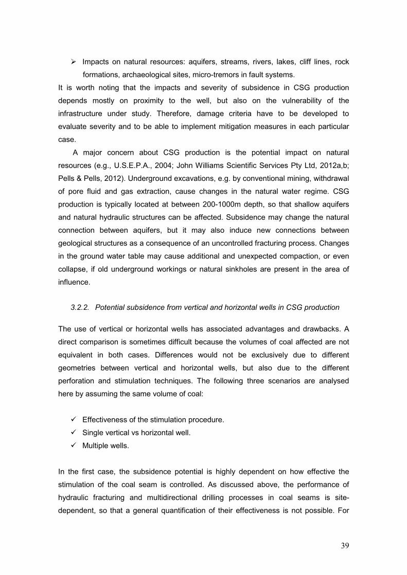
Impacts on natural resources: aquifers, streams, rivers, lakes, cliff lines, rock
formations, archaeological sites, micro-tremors in fault systems.
It is worth noting that the impacts and severity of subsidence in CSG production
depends mostly on proximity to the well, but also on the vulnerability of the
infrastructure under study. Therefore, damage criteria have to be developed to
evaluate severity and to be able to implement mitigation measures in each particular
case.
A major concern about CSG production is the potential impact on natural
resources (e.g., U.S.E.P.A., 2004; John Williams Scientific Services Pty Ltd, 2012a,b;
Pells & Pells, 2012). Underground excavations, e.g. by conventional mining, withdrawal
of pore fluid and gas extraction, cause changes in the natural water regime. CSG
production is typically located at between 200-1000m depth, so that shallow aquifers
and natural hydraulic structures can be affected. Subsidence may change the natural
connection between aquifers, but it may also induce new connections between
geological structures as a consequence of an uncontrolled fracturing process. Changes
in the ground water table may cause additional and unexpected compaction, or even
collapse, if old underground workings or natural sinkholes are present in the area of
influence.
3.2.2. Potential subsidence from vertical and horizontal wells in CSG production
The use of vertical or horizontal wells has associated advantages and drawbacks. A
direct comparison is sometimes difficult because the volumes of coal affected are not
equivalent in both cases. Differences would not be exclusively due to different
geometries between vertical and horizontal wells, but also due to the different
perforation and stimulation techniques. The following three scenarios are analysed
here by assuming the same volume of coal:
Effectiveness of the stimulation procedure.
Single vertical vs horizontal well.
Multiple wells.
In the first case, the subsidence potential is highly dependent on how effective the
stimulation of the coal seam is controlled. As discussed above, the performance of
hydraulic fracturing and multidirectional drilling processes in coal seams is site-
dependent, so that a general quantification of their effectiveness is not possible. For
40
the same volume of coal to be ‘affected’, horizontal drilling seems to give, at least in
theory, more satisfactory results if no issues are encountered during the drilling of the
horizontal wells. In both vertical and horizontal wells the subsidence bowl is expected
to be aligned according to the direction of the cleat system which controls the
permeability of the coal seam. A detailed geophysical characterization should be
employed to define the direction of the ‘stimulation’ technique and, in this way, to
predict the preferential alignment of the subsidence bowl.
A proper comparison of the potential subsidence between a single vertical and a
horizontal well should be made based on the assumption of a constant pumping rate in
both wells. Due to the lack of data on this, two possible scenarios are evaluated here in
terms of the expected changes in permeability obtained at the end of the ‘stimulation’
process. If the same increase in permeability is obtained after the stimulation process,
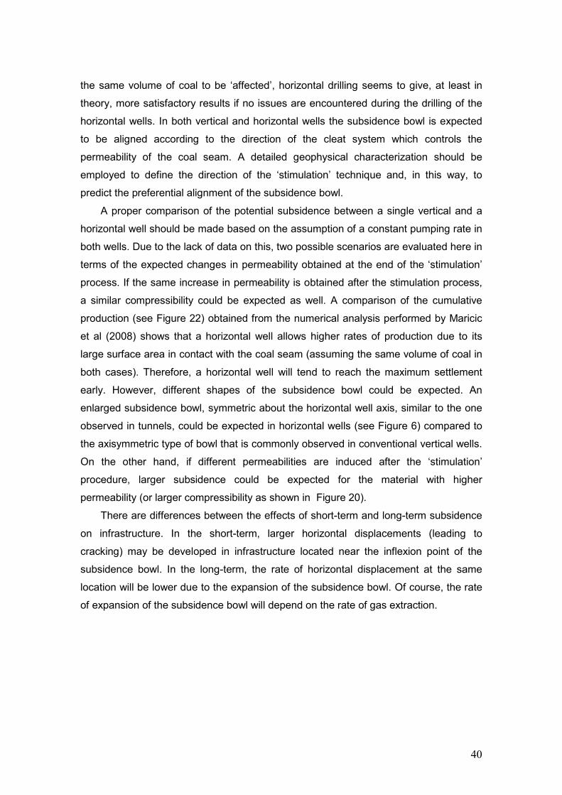
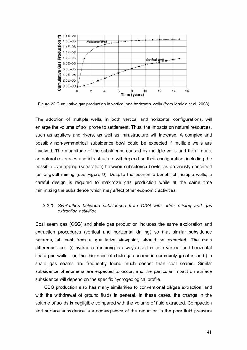
a similar compressibility could be expected as well. A comparison of the cumulative
production (see Figure 22) obtained from the numerical analysis performed by Maricic
et al (2008) shows that a horizontal well allows higher rates of production due to its
large surface area in contact with the coal seam (assuming the same volume of coal in
both cases). Therefore, a horizontal well will tend to reach the maximum settlement
early. However, different shapes of the subsidence bowl could be expected. An
enlarged subsidence bowl, symmetric about the horizontal well axis, similar to the one
observed in tunnels, could be expected in horizontal wells (see Figure 6) compared to
the axisymmetric type of bowl that is commonly observed in conventional vertical wells.
On the other hand, if different permeabilities are induced after the ‘stimulation’
procedure, larger subsidence could be expected for the material with higher
permeability (or larger compressibility as shown in Figure 20).
There are differences between the effects of short-term and long-term subsidence
on infrastructure. In the short-term, larger horizontal displacements (leading to
cracking) may be developed in infrastructure located near the inflexion point of the
subsidence bowl. In the long-term, the rate of horizontal displacement at the same
location will be lower due to the expansion of the subsidence bowl. Of course, the rate
of expansion of the subsidence bowl will depend on the rate of gas extraction.
41
Figure 22.Cumulative gas production in vertical and horizontal wells (from Maricic et al, 2008)
The adoption of multiple wells, in both vertical and horizontal configurations, will
enlarge the volume of soil prone to settlement. Thus, the impacts on natural resources,
such as aquifers and rivers, as well as infrastructure will increase. A complex and
possibly non-symmetrical subsidence bowl could be expected if multiple wells are
involved. The magnitude of the subsidence caused by multiple wells and their impact
on natural resources and infrastructure will depend on their configuration, including the
possible overlapping (separation) between subsidence bowls, as previously described
for longwall mining (see Figure 9). Despite the economic benefit of multiple wells, a
careful design is required to maximize gas production while at the same time
minimizing the subsidence which may affect other economic activities.
3.2.3. Similarities between subsidence from CSG with other mining and gas extraction activities
Coal seam gas (CSG) and shale gas production includes the same exploration and
extraction procedures (vertical and horizontal drilling) so that similar subsidence
patterns, at least from a qualitative viewpoint, should be expected. The main
differences are: (i) hydraulic fracturing is always used in both vertical and horizontal
shale gas wells, (ii) the thickness of shale gas seams is commonly greater, and (iii)
shale gas seams are frequently found much deeper than coal seams. Similar
subsidence phenomena are expected to occur, and the particular impact on surface
subsidence will depend on the specific hydrogeological profile.
CSG production also has many similarities to conventional oil/gas extraction, and
with the withdrawal of ground fluids in general. In these cases, the change in the
volume of solids is negligible compared with the volume of fluid extracted. Compaction
and surface subsidence is a consequence of the reduction in the pore fluid pressure

42
leading to an increase in effective stress. Similar shapes of the subsidence bowl could
be expected in these cases, particularly if compared with vertical wells.
The subsidence pattern observed in horizontal wells during CSG extraction is
similar to the subsidence bowl obtained during tunnelling operations, while the order of
magnitudes may differ. There, a symmetric settlement trough or subsidence bowl about
the tunnel axis is frequently observed. Multiple horizontal wells will display a similar
subsidence bowl as observed when two tunnels are drilled close to each other.
Subsidence bowls are superposed in a similar way as also observed in longwall mining
with multiple chain pillars (see Figure 9).
3.2.4. What are the potential ‘worst case scenarios’ for subsidence associated to CSG production
The definition of a potential ‘worst’ subsidence scenario is not straightforward, even
less if a detailed description of the site-conditions is not available. Such a scenario will
depend on the occurrence of different events, not necessarily taking place at the same
time, which are associated with particular hydro-geological circumstances. In terms of
subsidence the ‘worst’ scenario is perhaps the one leading to large settlements
affecting infrastructure and natural resources, as well as the gas production itself.
Based on geomechanics principles and some degree of speculation, the following
scenarios could develop:
Intense cracking may develop at the boundaries of the subsidence bowl if large
settlements occur. This may reduce the pressure of the pore fluid inside the coal
seam as it is connected with overlying strata. Intense cracking may cause important
stability problems on neighbouring infrastructure, depending on its proximity
regarding the well.
Another possible scenario involves the differential settlement caused by
overlapping of the subsidence bowls in cases of multiple wells. The time-dependent
evolution of the subsidence bowl means that the deformations experienced by
infrastructure are also evolving with time during CSG production. Depending on its
location, the deformations produced in the short-term may cause more damage to
buildings than those associated with long-term subsidence.
In the case of horizontal wells, drilling through fault systems or highly fractured
zones may also induce instability of the surrounding mass leading to sudden
volume changes.

43
Probably the ‘worst’ scenario of all possibilities (but also the rarest to take place in
CSG production) is the one that causes a collapse mechanism in the coal seam
itself or along the geological profile. Such collapse may occur if the ground
contains voids or cavities from old mine workings, chemical dissolution of carbonate
rocks, or suffusion in sandstone. Collapse failure occurs when the material (rock or
soil) loses strength and support. Uncontrolled hydraulic fracturing, at high fluid
pressures, enhances existing fractures/joints and may also induce new fractures in
the coal seam as well as in the underlying and overlying strata (thus degrading their
strength). Fractures and joints may also lead to new connections between existing
voids or cavities. The hydraulic connectivity between different strata may speed up
the formation of a collapse mechanism.
In all cases, the likelihood of problems during CSG will depend on many factors.
Detailed geophysical, geological and geotechnical characterization of the site has to be
carried out. A careful control of the hydraulic fracturing practice as well as a continuous
monitoring of the extraction process will be needed to minimize any dangerous
consequences.
3.3. Risk assessment and management of subsidence in CSG production
In simple terms, risk is defined as the expected consequences associated with a given
event. Considering the CSG extraction as the event to occur, the risk of subsidence,
Rsub, is defined as the likelihood of CSG extraction, PCSG-extraction, multiplied by the
induced-consequences, C(i):
)(iextractionCSGsub CPR ⋅= − (6)
where the subscript “i” refers to any factor (such as a structure, activity, etc) that is
prone to being affected by CSG extraction including infrastructure (access roads,
houses, building, etc) and natural resources (aquifers, rivers, lakes, etc) as discussed
above. In addition, C(i) depends mainly on two factors (see Figure 23): (i) the site-
conditions, and (ii) the particular features of the structure analysed. Site-conditions
include the hydro-mechanical properties of the coal seam and each geological stratum
within the entire profile involved in the CSG extraction. It is important to note that site-
conditions are highly influenced by the stimulation process as explained above. On the
other hand, the characteristics of the structure under consideration include the type of
structure (access road, building, house, aquifer, river), location relative to the well and
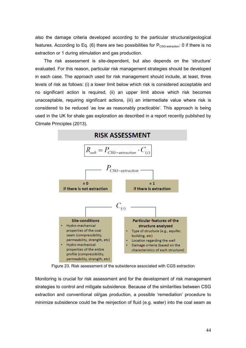
44
also the damage criteria developed according to the particular structural/geological
features. According to Eq. (6) there are two possibilities for PCSG-extraction: 0 if there is no
extraction or 1 during stimulation and gas production.
The risk assessment is site-dependent, but also depends on the ‘structure’
evaluated. For this reason, particular risk management strategies should be developed
in each case. The approach used for risk management should include, at least, three
levels of risk as follows: (i) a lower limit below which risk is considered acceptable and
no significant action is required, (ii) an upper limit above which risk becomes
unacceptable, requiring significant actions, (iii) an intermediate value where risk is
considered to be reduced ‘as low as reasonably practicable’. This approach is being
used in the UK for shale gas exploration as described in a report recently published by
Climate Principles (2013).
Figure 23. Risk assessment of the subsidence associated with CGS extraction
Monitoring is crucial for risk assessment and for the development of risk management
strategies to control and mitigate subsidence. Because of the similarities between CSG
extraction and conventional oil/gas production, a possible ‘remediation’ procedure to
minimize subsidence could be the reinjection of fluid (e.g. water) into the coal seam as
45
successfully employed to reduce the rate of subsidence in conventional oil/gas
reservoirs. A proper seal of the wells would be required to keep the reservoir
pressurized.
As explained in Section 2, reinjection of salt water into oil reservoirs reduced the
rate of subsidence almost completely at the Wilmington oil field (see Figure 12). At the
Ekofisk oil-field (see Figure 13) reinjection of water reduced substantially the rate of
subsidence from 42cm/yr to 15cm/yr. It is worth noting that gas is only released from
the coal once the pore fluid pressure reduces. This means that a modified protocol
should be implemented to avoid the premature cessation of gas extraction. A controlled
re-injection protocol, in which both gas pressure and injected fluid are carefully
manipulated, could be an alternative to control subsidence. The key point is to find the
equilibrium between extraction pressure and the injected fluid pressure. Some
problems could appear in cases where hydraulic fracturing was uncontrolled and
extended to the ground surface.
Another option to control subsidence and, at the same time, to extract gas from
coal seams is the re-injection of anthropogenic CO2. The sequestration of CO2 into the
coal seam represents, a priori, and additional environmental benefit. The injection of
CO2 into the coal seam allows an easy displacement of the methane from the coal
micro-pores by changing their polymer-like structure. CO2 diffuses into the coal micro-
pores in the same way as the methane was stored (Reucroft & Patel, 1986). Despite
their a priori benefits, there are some issues regarding the interaction between coal,
CO2 and methane, which are not well-understood. The changes in the polymer-like
structure of the coal seam, when exposed to CO2, reduces its strength and stiffness
and induces swelling of the coal matrix (Reucroft & Patel, 1986; Walker et al, 1988;
Masoudian et al, 2011,2012). This causes irreversible changes in the coal permeability
(e.g., Palmer & Mansoori, 1986; Masoudian et al, 2011). Further research is required in
this regard.
Continuous monitoring is fundamental during and after the implementation of any
mitigation measure. This will allow the process to be updates as the extraction
proceeds, with the aim of minimizing the subsidence potential.
46
4. Issues and knowledge gaps regarding subsidence caused by CSG production
Subsidence associated with CSG extraction is a coupled hydro-mechanical
phenomenon caused by the reduction of the pore fluid pressure when extracting the
methane from the coal seam. As schematically represented in Figure 24, the unique
characteristics of the coal, in combination with the exploration techniques used to
extract the gas, makes the subsidence a complex multi-phase and site-dependent
problem. Despite the experience acquired during recent decades in CSG engineering,
the phenomenon is not completely understood. Additional efforts should be made to
improve our engineering knowledge. The following aspects particularly deserve further
study:
a) Detailed hydro-mechanical characterization: both in-situ and laboratory
techniques have to be combined to obtain a detailed characterization of the coal
seam as well as the soil/rocks composing the entire geological profile.
Measurements of the hydromechanical properties (permeability, diffusivity,
adsorption isotherm, compressibility, stiffness and the in-situ stress) will provide a
proper reference, not only for design purposes but also for evaluating changes
during the lifespan of the well. In-situ (e.g., pre-fracture) well tests and laboratory
tests should be combined to reduce uncertainties caused by scale effects. It has
been recognized by several authors (see e.g., Loftin, 2009; Liu et al, 2011; Clarkson
et al, 2012) that the fluid storage and transport mechanisms in CSG production are
not fully understood. One of the main reasons for this is the lack of information about
the cleat system, a natural open-mode fracture system, which controls both the
hydraulic and mechanical properties of the coal seam. Their influence should be
thoroughly determined as the cleat system displays a natural-preferential alignment
which seems to be essential for a successful exploration and gas production
(Laubach et al, 1998) and for determining a possible preferred alignment of the
subsidence bowl. Compressibility and strength measurements along the entire
profile will be useful in subsequent settlement analysis of different strata and also in
stability estimations. The localization of weak strata or fault systems along the well
alignment (vertical or horizontal) should be also detected and properly
characterized.
b) Stimulation techniques and evaluation of hydraulic properties: stimulation
techniques have to be controlled carefully to avoid impacts on underlying and/or
47
overlying strata. Further study is required for a better understanding on the real
impacts of hydraulic fracturing within the coal seam including its effectiveness and
the formation of preferential paths. To do that, the study of the cleat system and its
relation to fracture propagation is crucial (e.g., Laubach et al, 1998; Loftin, 2009; Liu
& Rutqvist, 2010; Liu et al, 2011). The cleat system plays a key role during gas
extraction. However, their evolution/response during stimulation and gas extraction
has not been analysed in detail. A detailed characterization of the in-situ stress field
should help to improve the practice of hydraulic fracturing by limiting the injection
pressures to values just above the minor principal stress when “fracking”. The
influence of hydraulic fracturing on the permeability and compressibility require
additional experimental and theoretical analysis. Quantitative models for
characterising these influences will lead to refinements in the analysis of
subsidence. Experience gained in pre- and post-fracture well test analyses in shale
gas extraction may help to evaluate the effectiveness of the stimulation procedures
used in CSG extraction (Clarkson et al, 2012), but taking into account the particular
features of the coal seam.
c) Detailed monitoring: monitoring is possibly the most important factor, not only
to improve subsidence analysis but also in the control of gas production. Detailed
monitoring of pressures and relative displacements inside the coal seam will allow a
proper quantification, in almost real time, of the compaction process of the coal
seam. In addition, monitoring in overlying and underlying strata can be used to
detect changes in the hydraulic regime and to estimate the induced-compaction.
Monitoring can also be used for the development of subsidence contours and
subsidence bowls. From this, mitigation measures and risk maps could be
implemented for each particular case. Some examples of the benefits of a detailed
monitoring were given in Section 2 (see Figures 11, 12 and 13). A detailed
monitoring program seems to be a convenient option to improve and update current
models used for subsidence analysis.
d) Multi-phase models: the former three aspects should be used to improve
and/or develop new constitutive models including the particular characteristics of the
coal seams. A multi-phase approach seems to be the best option to include the
different coupling mechanisms that act naturally in the coal seam and control their
hydraulic and mechanical responses such as the induced-subsidence.

48
Figure 24.Schematic representation of subsidence in CSG extraction

49
5. Final remarks
A review of the main causes of subsidence is presented in this paper, with particular
emphasis on the subsidence caused by coal seam gas extraction. CSG extraction is
gaining more interest as an untapped energy source in Australia. In a recent study,
John Williams Scientific Services Pty Ltd (2012a) pointed out the necessity for a new
focus in research and academic leadership to support the development of CSG
production in Australia. A holistic perspective in teaching and research involving
multidisciplinary scenarios is required to study coal seam gas energy production. New
scientific and engineering knowledge will provide essential tools to manage CSG
production and to evaluate its effects on natural resources and infrastructures.
CSG production involves several processes affecting not only the properties of the
coal seam itself but also the entire geological profile. It does not necessarily represent
a drawback for CSG extraction if those processes, many of them acting in a coupled
way, are properly understood and ‘controlled’. CSG extraction is a multi-phase problem
in which multidisciplinary work is the best option to improve current practice and also to
develop a framework of behaviour for CSG extraction, including improvements to
evaluate subsidence. Based on the discussion presented in the previous sections, the
following remarks related to subsidence caused by CSG extraction can be made:
i. Subsidence is caused by the compression of the coal seam as a
consequence of the reduction of the pore fluid pressure (by gas extraction)
that increases the effective stress.
ii. Subsidence is a complicated issue in CSG extraction. It can vary in
magnitude, from trivial and insignificant to substantial and damaging,
depending on the mechanical properties of the coal seam, the volume of
gas extracted, the extraction methods and most importantly the geological
setting of the coal seam. Subsidence is expected to increase if additional
compaction takes place in overlying and/or underlying strata due to
changes in the hydraulic regime (e.g. de-watering).
iii. Subsidence is further complicated by the influence of a stimulation
procedure or hydraulic fracturing. Uncontrolled hydraulic fracturing with
high fluid pressures may induce fractures in the coal seam as well as in
underlying and overlying strata, and hence degrade their strength. The
hydraulic connectivity between different strata may accelerate subsidence.
50
iv. Different subsidence bowls are expected if vertical or horizontal well
configurations are used for gas extraction. The magnitude of the induced-
subsidence may not be compared easily, as different volumes of coal and
different gas production rates are involved in each case.
v. It is expected that multiple wells will enhance and complicate the
subsidence bowl in both cases. The overlapping of the subsidence bowls
will depend on the separation length between wells but also on the
effectiveness of the stimulation and extraction processes.
vi. Permeability is a key factor controlling the performance of the well,
irrespective of the extraction method. Changes in permeability caused by
the stimulation process will affect the compressibility of the coal seam and
thus the amount of subsidence. These changes should be carefully
estimated before starting the gas extraction.
vii. Many of the coupled multi-physical processes involved in CSG extraction
are not completely understood. Further research is needed to answer
unsolved questions. Of particular interest is the determination of the
transport properties and their effects on the mechanical behaviour of the
coal. A detailed characterization of the cleat system will give clues for the
improvements of permeability models and their influence on the coal
compressibility which drives the compaction process.
viii. Detailed monitoring throughout the entire profile is crucial for a better
understanding of the subsidence phenomenon in CSG extraction.
Mitigation techniques developed for each particular case (e.g., water or
CO2 injection) should be updated according to the monitoring data. Further
research is also required in this field. Monitoring is also required for
updating and improving models of subsidence, which will help to develop a
solid framework for the production of CSG in Australia.
Acknowledgements
Professors Stephen Fityus and Scott Sloan at the University of Newcastle read this
report and provided thoughtful suggestions and comments. Their contribution is greatly
appreciated.
51
References Al-Homoud A.S., Basma A.A., Husein Malkawi & Al-bashabsheh (1995) Cyclic swelling
behaviour of clays. Journal of Geotechnical Engineering, 121, 562-565. Allen D.R. & Mayuga M.N. (1969) The mechanics of compaction and rebound,
Wilmington oil field, Long Beach, California, USA. Land Subsidence, vol 2, 410-422.
Allman M.A., Delaney M.D. & Smith D.W. (1998) A field study of seasonal ground movements in expansive soils. In Prof. 2nd Int Conf. on Unsaturated Soils, International Academic Publishers, Beijing, 309-314.
Bai M. & Kendorski F.S. (1985) Chinese and North American high-extraction underground coal mining strata behaviour and water protection experience and guidelines. 14th Conference on Ground Control in Mining, 209-217.
Brighenti G., Borgia G.C. & Mesini E. (1995) Subsidence studies in Italy. Subsidence due to fluid withdrawal, Developments in Petroleum Science 41, 248-253.
Buzzi O., Fityus S.G., Sasaki Y. & Sloan S.W. (2008) Structure and properties of expanding polyurethane resin in the context of foundation remediation in expansive soil. Mechanics of Materials, 40(12), 1012-1021
Buzzi O., Fityus S.G., Sloan S.W. (2009). The use of expanding polyurethane resin to remediate expansive soil foundations. Canadian Geotechnical Journal, 47(6), 623-634.
Cording E.J., Son M., Laefer D., Long J. & Ghahreman B. (2008) Examples of building response to excavation and tunnelling. In Proc. PaymaCotas Lectures in Tunnelling Engineering: Movements in Buildings induced by Excavations, Damage Criteria and Risk. Technical University of Catalonia, UPC-Barcelona, (https://www.etcg.upc.edu/la-docencia/aula-paymacotas), 69-93.
Clarkson C.R., Jensen J.L. & Chipperfield S. (2012) Unconventional gas reservoir evaluation: What do we have to consider?. Journal of Natural Gas Science and Engineering, 8, 9-33.
Climate Principles (2013) Shale gas exploration and production. Key issues and responsible business practices. Guidance notes for financers. Final Report, March, 34p.
Close J. C. (1993) Natural Fractures in Coal. AAPG Studies in Geology Hydrocarbons from Coal, 119-133.
CSIRO (2012) Coal Seam Gas developments – predicting impacts. April, (www.csiro.au).
Doornhof D., Kristiansen T.G., Nagel N.B., Pattillo P.D. & Sayers C. (2006) Compaction and subsidence. Oilfield review, Autumn, 50-68.
Figueroa-Vega G. (1984) Guidebook to studies of land subsidence due to ground-water withdrawal: Chapter 9: Case History 9.8. Mexico, D.F., Mexico. International Hydrological Programme, Working Group 8.4, UNESCO®, American Geophysical Union. Chapter 9, 217-232.
Finno R. & Roboski J.F. (2005) Three-dimensional responses of a tied-back excavation through clay. Journal of Geotechnical and Geoenvironmental Engineering, 131(3), 273-285
Fityus S.G., Smith D.W. & Allman M.A. (2004) Expansive soil test site near Newcastle. Journal of Geotechnical and Geoenvironmental Engineering, 130(7), 686-695.
Fokker P.A. (2002) Subsidence prediction and inversion of subsidence data. In SPE/ISRM Rock Mechanics Conference, Irving, Texas.
Fokker P.A. & Orlic B. (2006) Semi-analytical model of subsidence. Mathematical Geology, 38(5), 565-589.
52
Fredrich J.T., Arguello J.G., Deitrick G.L. & de Rouffignac E.P. (2000) Geomechanical modelling of reservoir compaction, surface subsidence and casing damage at belridge diatomate field. SPE Reservoir Evaluation and Engineering, 3(4), 348-359.
Geertsma J. (1973) A basic theory of subsidence due to reservoir compaction: the homogenous case. Verhandelingen van het Koninklijk Nederlands geologish mijnbouwkundig Genootchap, 28, 43-62.
Geertsma J. & van Opstal G. (1973) A numerical technique for predicting subsidence above compacting reservoirs based on the nucleus of strain concept. Verhandelingen van het Koninklijk Nederlands geologish mijnbouwkundig Genootchap, 28, 63-78.
Heine C., Muller D., Stainberger B. & Torsvik T. (2008. “Subsidence in intracontinental basins due to dynamic topography” Physics of the earth and planetary interiors, 171, 252-264.
Holla L. & Barclay E. (2000) Mine subsidence in the Southern Coalfield, NSW, Australia. NSW Department of Mineral Resources.
Holla L. & Thompson K.J. (1992) A study of ground movement in three orthogonal directions due to shallow multi-seam longwall mining. The Australian Coal Journal, No. 8.
ITA/AITES (2007) Settlement induced by tunnelling in soft ground. Tunnelling and Underground Space Technology, 22, 119-149.
Jahangir E., Deck O. & Masrouri F. (2012) Estimation of ground settlement beneath foundations due to shrinkage in clayey soils. Canadian Geotechnical Journal, 49, 835-852.
John Williams Scientific Services Pty Ltd (2012a) Some ways forward for coal seam gas and natural resource management in Australia. Summary Report, October, 20p.
John Williams Scientific Services Pty Ltd (2012b) An analysis of coal seam gas production and natural resource management in Australia: Issues and ways forward. Final Report, October, 116p.
Kapp W.A. Mine subsidence and strata control in the Newcastle district of the norther coalfield New South Wales. PhD Thesis, University of Wollongong.
Kapp. W.A. & Kennerley (1986) Subsidence and strata control under stored waters in the southern coalfield New South Wales. In Proc. Symposium Ground Movement and Control related to Coal Mining, 341-351.
Ketelaar V.B.H. (2009) Satellite Radar Interferometry. Subsidence Monitoring Techniques. Springer Series Book, 7-26.
Laubach S.E., Marret R.A., Olson J.E. & Scott A.R. (1998) Characteristics and origins of coal cleat: a review. International Journal of Coal Geology, 35, 175-207.
Li G., Steuart P. & Paquet R. (2007) A case study on multi-seam subsidence with specific reference to longwall mining under existing longwall goaf. In Proc. 7th Triennal Conference on Mine Subsidence, Sydney, NSW, 111-125.
Liu J. & Rutqvist J. (2010) A new coal-permeability model: internal swelling stress and fracture-matrix interaction. Transport in Porous Media, 82(1), 157-171.
Liu J., Chen Z., Elsworth D., Qu H. & Chen D. (2011) Interactions of multiple processes during CBM extraction: a critical review. International Journal of Coal Geology, 87, 175-189.
Loftin P. (2009) Thirty years of lessons learned – Tips and tricks for finding, developing and operating a coalbed methane field. In Proc 24th World Gas Conference ‘The Global Energy Challenge: Reviewing the Strategies for Natural Gas’. 5-9 October, Argentina.
53
Maricic N., Mohaghegh S.D. & Artun E. (2008) A parametric study on the benefits of drilling horizontal and multilateral wells in coalbed methane reservoirs. SPE Reservoir Evaluation & Engineering, December, 976-983.
Masoudian M.S., Airey D.W., Gainey A., Morris T. & Beger J. (2011) The mechanical properties of CO2-saturated coal specimens. In Proc. Int. Conference on Rock Mechanics, Beijing, China.
Masoudian M.S., Airey D.W. & El-Zein A. (2012a) Softening effect of CO2 and its influence on reservoir simulation and permeability prediction. In. Proc. ANZ Australian New Zeland Conference, 997-1002.
Masoudian M.S., Airey D.W. & El-Zein A. (2012b) The effect of CO2 on micro structure and mechanical properties of Australian black coal. In. Proc. ANZ Australian New Zealand Conference, 728-733.
Mayuga M.N. & Allen D.R. (1969) Subsidence in the Wilmington oil field, Long Beach, California, USA. Land Subsidence, Vol 1, 66-79.
MSEC- Mine Subsidence Engineering Consultants (2012) Ashton Coal Operations Limited: Upper Liddell Seam – Longwalls 1 to 8. Technical Report, February.
Narasimhan, T.N., and Goyal, K.P., 1984, Subsidence due to geothermal fluid withdrawal, in Holzer, T.L., editor, Man-induced land subsidence: Geological Society of America Reviews in Engineering Geology, v. 6, p. 35–66.
Palmer I. & Mansoori J. (1996) How permeability depends on stress and pore pressure in coalbeds: a new model. SPE Annual Technical Conference and exhibition, Denver Colorado, U.S.A.
Peck, R.B. (1969). Deep excavations and tunnelling in soft ground, SOA Report. 7th Int Conf. SM&FE, Mexico City, State of the Art Volume, pp225-290.
Pells S.E. & Pells P.J.N. (2012) Impacts of longwall mining and coal seam gas extraction on groundwater regimes in the Sydney basin. Part 2: practical applications. Australian Geomechanics Journal, 47(3), 51-68.
Poland J.F. (1984) Guidebook to studies of land subsidence due to ground-water withdrawal: Chapter 3: Mechanics of land subsidence due to fluid withdrawal. International Hydrological Programme, Working Group 8.4, UNESCO®, American Geophysical Union. Chapter 3, 37-54.
Poland J.F., Lofgren B.E., Ireland R.L. & Pugh R.G. (1975) Land subsidence in the San Joaquin Valley, California. U.S. Geol. Survey Prof. Paper 437-H, 77p.
Pratt W.E. & Johnson D.W. (1926) Local subsidence of the Goose Creek oil field (Texas). Journal of Geology, 34(7), 577-590.
Reucroft P.J. & Patel H. (1986) Gas-induced swelling in coal. Fuel, 65, 816-820. Rupert F. & Spencer S. (2004) Florida’s sinkholes. U.S. Geological Survey, Poster
No.11 (www.dep.state.fl.us) Savalli L. & Engelder T. (2005) Mechanisms controlling rupture shape during
subcriutical growth of joints in layered rock. Geological Society of America Bulletin 117, 436-449.
Seedsman Geotechnics Pty Ltd (2012). South Galilee Coal Project. Life of Mine Subsidence Deformations. Geotechnical Report, March.
Seedsman Geotechnics Pty Ltd (2011). Gujarat NRE No 1 Colliery. Management of subsidence risks associated with Wongawilli Seam extraction with particular focus on Wongawilli East-Area 2. Geotechnical Report, July.
Sheng D., Sloan S.W., Gens A. & Smith D.W. (2003a) Finite element formulation and algorithms for unsaturated soils, Part I: Theory. International Journal for Numerical & Analytical Methods in Geomechanics, 27(9), 745-765.
Sheng D., Smith D.W., Sloan S.W. & Gens A. (2003b) Finite element formulation and algorithms for unsaturated soils, Part II: Verification. International Journal for Numerical & Analytical Methods in Geomechanics, 27(9), 767-790.
54
Sheng D., Sloan S.W. & Gens A. (2004) A constitutive model for unsaturated soils: thermomechanical and computational aspects. Computational Mechanics, 33(6), 453-465.
Sheng D., Fredlund D.G. & Gens A. (2008) A new modelling approach for unsaturated soils using independent stress variables. Canadian Geotechnical Journal, 45(4), 511-534.
Sinclair W.C. & Stewart J.W. (1985) Sinkhole type, development and distribution in Florida. Florida Geological Survey Map Series No. 110, Tallahasse, Florida, 1p.
Singh K.B. & Dahr B.B. (1997) Sinkhole subsidence due to mining. Geotechnical and Geological Engineering, 15, 327-341.
Sroka A. & Hejmanowki R. (2006) Subsidence prediction caused by the oil and gas development. In 3rd IAG Symposium on Geodesy for Geotechnical and Structural Engineering, Baden, Austria.
Terzaghi K. (1925) Principles of soil mechanics. New York: Mc-Graw Hill. USEPA (2004) Evaluation of impacts to underground sources of drinking water by
hydraulic fracturing of coalbed methane reservoirs. United States Environmental Protection Agency, Final Report, June. 463p.
Walker P.L., Verma S.K., Riverautrilla & Khan M.R. (1988) A direct measurement of expansion in coals and macerals induced by carbon dioxide and methanol. Fuel, 67, 719-726.
Xie X. & Heller P. (2009) Plate tectonics and basin subsidence history. Geological Society of American Bulletin, 121(1-2), 55-64.
Zhou A.N., Sheng D., Sloan S.W. & Gens A. (2012a) Interpretation of unsaturated soil behaviour in the stress - saturation space, I: Volume change and water retention behaviour. Computers and Geotechnics, 43, 178-187.
Zhou A.N., Sheng D., Sloan S.W. & Gens A. (2012b) Interpretation of unsaturated soil behaviour in the stress - saturation space, II: Constitutive relationships and validations. Computers and Geotechnics, 43, 111-123.
Zhou A.N., Sheng D. & Carter J. P. (2012c). Modelling the effect of initial density on soil-water characteristic curves, Geotechnique , 62(8): 669-680.


