
June 14-15, 2006/ARR1
ARIES-CS Power Core Engineering:Updating Power Flow, Blanket and Divertor Parameters
for New Reference Case (R = 7.75 m, Pfusion = 2355 MW)
Presented by A. René Raffray
University of California, San Diego
ARIES MeetingUCSD, La Jolla, CA
June 14-15, 2006

June 14-15, 2006/ARR2
Pfusion
Pneutron
P
P,loss
Div
erto
r
Fir
st W
all
(in
clu
din
g s
pec
ial
m
od
ule
s if
pre
sen
t)
Prad,chamb
Pparticle
80%
20%
Prad,div_reg
f,loss
frad,core
1-f,loss-frad,core
Fdiv,peak
FFW,peak
f,div
1-f,div
F,div,peak
F,FW,peak
Padded
frad,edge
1-frad,edge
Prad,edge
frad,edge,div
1-frad,edge,div
frdr,div
1-frdr,div
Prad,sol
Comprehensive Power Flow Diagram Including Possibility of Added Power and Alpha Loss Flux Going to Both FW and Divertor
(including J. Lyon’s input, June 1, 2006)
fgeo,div
1-fgeo,div
fgeo,div
1-fgeo,div
fgeo,div
1-fgeo,div
June 14-15, 2006/ARR3
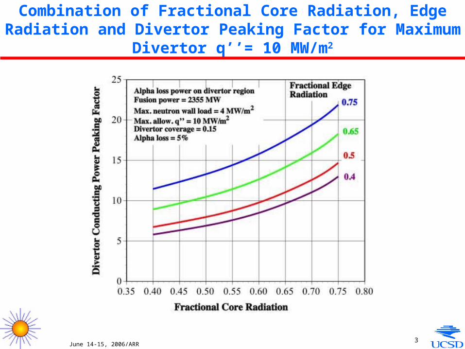
Combination of Fractional Core Radiation, Edge Radiation and Divertor Peaking Factor for Maximum Divertor q’’= 10 MW/m2

June 14-15, 2006/ARR4
ARIES-CS Power Estimate for Reference Case with R = 7.75 m Fusion power (MW) 2355 Neutron power (MW) 1884 Alpha power (MW) 471 FW surface area (m2) 727.7 Avg neutron wall load (MW/ m2) 2.59 Wall load peaking factor 1.52 Max neutron wall load (MW/m2) 3.94 Alpha loss fraction 0.05 Alpha loss power (assumed to all go to to divertor) (MW) 23.55 Fraction of core power radiated (frad,core) 0.75 Radiated core power (MW) 353.25 Radiated core power to FW (MW) 314.4 Radiated core power to divertor (MW) 38.86 Particle power (MW) 94.2 Fraction of particle power radiated at edge (frad,edge) 0.75 Radiated edge power (MW) 70.65 Conducted power reaching divertor plates (MW) 23.55 Fraction of edge power radiated from divertor region, (frad,edge,div) 0.5 Edge power radiated in divertor region(MW) 35.33 Edge power radiated from SOL to all FW including divertor (MW) 35.33 Fraction of edge power radiated from divertor region going to divertor (frdr,div) 0.5 Edge power radiated from divertor region going to divertor (MW) 17.66 Edge power radiated from divertor region going to FW only (MW) 17.66

June 14-15, 2006/ARR5
FIRST WALL Tot al Surface Power to FW (MW) 363.5 Average first wall heat flux (MW/m2) 0.59 FW heat flux peaking factor for core and edge radiation on total area 1.52 Max. first wall heat flux on regular module (MW/m2) 0.81 DIV ERTOR (I NCLUDING ALPHA LOSS) Conducted power peaking factor on divertor plates 21.9 Divertor fractional coverage 0.15 Eff. D iv. coverage (accounting for geometry effect) 0.11 Divertor surface area (m2) 109.16 Surface power to the divertor including alpha loss component (MW) 107.51 Max. heat flux on divertor including alpha loss component (MW/ m2) 10.0 Avg. heat flux on divertor including alpha loss component (MW/ m2) 0.985 THERMAL POWER IN BLANKET AND DIV ERTOR Energy multiplication factor 1.15 Tot al fusion thermal power in reactor (MW) 2637.6 Neutron thermal power to blanket excluding (divertor+alpha loss) regions(MW) 1841.6 Thermal power to blanket excluding (divertor+alpha loss) regions(MW) 2205.1 Surface power to divertor region (MW) 107.5 Assumed fraction of neutron power to divertor in divertor region 0.287 Tot al thermal power to divertor region (including neutrons) (MW) 200.78 Thermal power to blanket behind divertor (MW) 231.7 Tot al thermal power to blanket (MW) 2436.8 Fractional thermal power to blanket 0.923 Fractional thermal power to divertor 0.076
June 14-15, 2006/ARR6
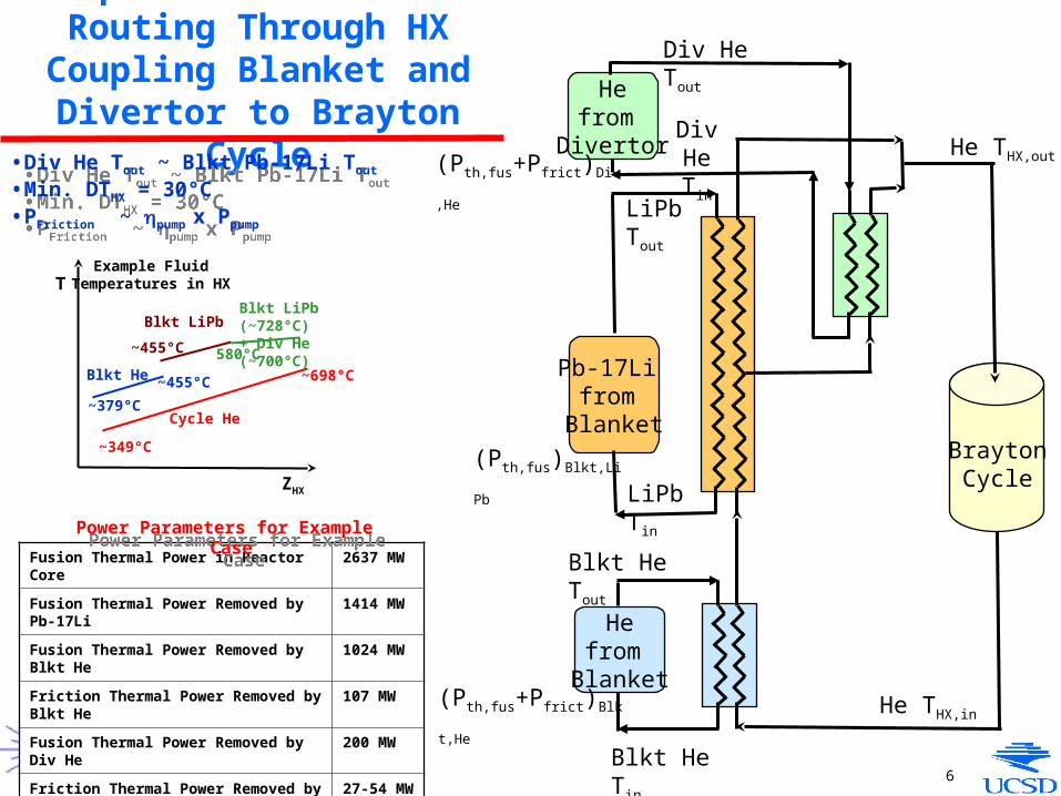
Update of Coolant Routing Through HX Coupling Blanket and Divertor to Brayton Cycle
• Div He Tout ~ Blkt Pb-17Li Tout
• Min. DTHX = 30°C• PFriction ~ pump x Ppump
• Div He Tout ~ Blkt Pb-17Li Tout
• Min. DTHX = 30°C• PFriction ~ pump x Ppump
Fusion Thermal Power in Reactor Core 2637 MW
Fusion Thermal Power Removed by Pb-17Li 1414 MW
Fusion Thermal Power Removed by Blkt He 1024 MW
Friction Thermal Power Removed by Blkt He 107 MW
Fusion Thermal Power Removed by Div He 200 MW
Friction Thermal Power Removed by Div He 27-54 MW
Fusion + Friction Thermal Power in Reactor Core
2771-2798 MW
Power Parameters for Example CasePower Parameters for Example Case
Blkt He
Example Fluid Temperatures in HX
Blkt LiPbBlkt LiPb (~728°C)+ Div He (~700°C)
Cycle He
~698°C
580°C
~379°C
~455°C
~455°C
~349°C
T
ZHX
Pb-17Li from
Blanket
Hefrom
Divertor
Hefrom
Blanket
BraytonCycle
He THX,out
He THX,in
Blkt He Tin
Blkt He Tout
(Pth,fus+Pfrict)Blkt,He
(Pth,fus)Blkt,LiPb
LiPb Tin
LiPb Tout
Div HeTin
Div He Tout
(Pth,fus+Pfrict)Div,He

June 14-15, 2006/ARR7
Updated DC Blanket Parameters for New Reference
Case and Power Flow Assumptions from J. Lyon
Blanket Updated Values Previous Values
Typical Module Dimensions 2m x 2m x 0.62 m 2m x 2m x 0.62 m
Tritium Breeding Ratio 1.1 1.1
Fusion Thermal Power in Blanket 2430 MW 2367 MW
Blanket Pb-17Li Coolant
Pb-17Li Inlet Temperature 462°C 500°C
Pb-17Li Outlet Temperature 727°C 710°C
Pb-17Li Inlet Pressure 1 MPa 1 MPa
Typical Inner Channel Dimensions 0.26 m x 0.24 m 0.26 m x 0.24 m
Thickness of SiC Insulator in Inner Channel 5 mm 5 mm
Effective SiC Insulator Region Conductivity 200 W/m2-K 200 W/m2-K
Average Pb-17Li Velocity in Inner Channel ~0.04 m/s <~0.1 m/s
Fusion Thermal Power removed by Pb-17Li 1410 MW 1373 MW
Pb-17Li Total Mass Flow Rate 28,500 kg/s 35,100 kg/s
Pb-17Li Pressure Drop ~0.4 kPa <~1 kPa
Pb-17Li Pumping Power ~ 2 kW <~ 4.7 kW
Maximum Pb-17Li/FS Temperature 474°C 500°C
Blanket He Coolant
He Inlet Temperature 379°C 368°C
He Outlet Temperature 455°C 486°C
He Inlet Pressure 10 MPa 10 MPa
Typical FW Channel Dimensions (poloidal x radial) 2 cm x 3 cm 2 cm x 3 cm
He Velocity in First Wall Channel 46.4 m/s 56.6 m/s
Total Blanket He Pressure Drop 0.26 MPa 0.34 MPa
Fusion Thermal Power Removed by He 1020 MW 994 MW
Friction Thermal Power Removed by He 105 MW 87 MW
Total Mass Flow Rate 2980 kg/s 1830 kg/s?
Pumping Power 117 MW 97 MW
Maximum Local ODS/RAFS Temperature at FW 643/564°C 654°C
Radially Avg ODS/RAFS Temp. at Tmax Location 604/550°C 596°C
3-mm ODS FS Tmax/Tmin/Tavg =643°C/564°C/604°C
Tcool = 426 °C
FW He Coolant
Plasma heat flux
1-mm RAFS Tmax/Tmin/Tavg =564°C/536°C/550°C
• R = 7.75 m• Fusion power = 2355 MW• Avg/max. wall load = 2.59/3.94 MW/m2 • Avg/max. plasma q’’ = 0.59/0.81 MW/m2
June 14-15, 2006/ARR8
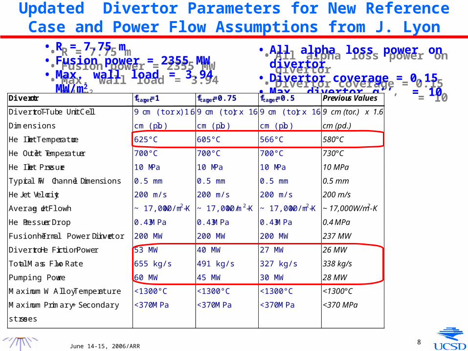
Updated Divertor Parameters for New Reference Case and Power Flow Assumptions from J. Lyon
• R = 7.75 m• Fusion power = 2355 MW• Max. wall load = 3.94 MW/m2
• R = 7.75 m• Fusion power = 2355 MW• Max. wall load = 3.94 MW/m2
• All alpha loss power on divertor• Divertor coverage = 0.15• Max. divertor q’’ = 10 MW/m2
• All alpha loss power on divertor• Divertor coverage = 0.15• Max. divertor q’’ = 10 MW/m2
Divertor ftarget=1 ftarget=0.75 ftarget=0.5 Previous Values
Divertor T-Tube Unit Cell
Dimensions
9 cm (tor.) x 1.6
cm (pol.)
9 cm (tor.) x 1. 6
cm (pol.)
9 cm (tor.) x 1. 6
cm (pol.)
9 cm (tor.) x 1.6
cm (pol.)
He Inlet Temperature 625°C 605°C 566°C 580°C
He Outlet Temperature 700°C 700°C 700°C 730°C
He Inlet Pressure 10 MPa 10 MPa 10 MPa 10 MPa
Typical FW Channel Dimensions 0.5 mm 0.5 mm 0.5 mm 0.5 mm
He Jet Velocity 200 m/s 200 m/s 200 m/s 200 m/s
Average Jet Flow h ~ 17,000 W/m2-K ~ 17,000 W/m2-K ~ 17,000 W/m2-K ~ 17,000 W/m2-K
He Pressure Drop 0.43 MPa 0.43 MPa 0.43 MPa 0.4 MPa
Fusion Thermal Power in Divertor 200 MW 200 MW 200 MW 237 MW
Divertor He Friction Power 53 MW 40 MW 27 MW 26 MW
Total Mass Flow Rate 655 kg/s 491 kg/s 327 kg/s 338 kg/s
Pumping Power 60 MW 45 MW 30 MW 28 MW
Maximum W Alloy Temperature <1300°C <1300°C <1300°C <1300°C
Maximum Primary + Secondary
stresses
<370 MPa <370 MPa <370 MPa <370 MPa

June 14-15, 2006/ARR9
• He mass flow = 12 kg/s and P ~ 0. 34 MPa per 2m x 1 plate under the assumed heat flux profile
• For our large divertor coverage, what fraction of the divertor (ftarget) should we assume under such a “target plate” heat load scenario?
• He mass flow = 12 kg/s and P ~ 0. 34 MPa per 2m x 1 plate under the assumed heat flux profile
• For our large divertor coverage, what fraction of the divertor (ftarget) should we assume under such a “target plate” heat load scenario?
Assumed Divertor Target Heat Load Distribution and Manifolding Scheme (from T. Ihli)

June 14-15, 2006/ARR10
Updated Data for System Code Based on New Power Flow Assumptions from J. Lyon
Dual Coolant Blanket Pumping Power
(Previously, divertor pumping power ~28 MW)
Dual Coolant Blanket Pumping Power
(Previously, divertor pumping power ~28 MW)
Max. Neutron Wall Load
Cycle Efficiency
(Updated)
Blanket Pumping Power (MW)
(Updated)
Divertor Pumping Power (MW)
(Updated)
ftarget=1
Divertor Pumping Power (MW)
(Updated)
ftarget=0.5
Cycle Efficiency
(Old)
Blanket Pumping Power (MW)
(Old)
1.5 MW/m2 0.441 48
2 MW/m2 0.448 66 118 59 0.436 53
3 MW/m2 0.442 102 78 9 0.432 74
4 MW/m2 0.424 118 60 30 0.423 85
5 MW/m2 0.405 138 47 23.5 0.414 97

June 14-15, 2006/ARR11
1. F. Najmabadi, “The ARIES-CS Study? “(abstract?)
2. L. P. Ku and the ARIES Team, “Configuration Optimization and Physics Basis of ARIES-CS”
3. J. F. Lyon, L.P. Ku, L. El-Guebaly, L. Bromberg and the ARIES Team, “Optimization of the ARIES-CS Compact Stellarator Power Plant Parameters”
4. A. R. Raffray, L. El-Guebaly, T. Ihli, S. Malang, X. Wang and the ARIES-CS Team, “Engineering Design and Analysis of the ARIES-CS Power Plant”
5. L. El-Guebaly, R. Raffray, S. Malang. J. Lyon, L.P. Ku, X. Wang, P. Wilson, D. Henderson, T. Tautges, M. Sawan, G. Sviatoslvsky, B. Kiedrowski, M. Wang, C. Martin, B. Merrill, and the ARIES Team, “Overview of ARIES-CS In-vessel Components: Integration of Nuclear, Economic, and Safety Constraints in Compact Stellarator Design”
6. Lester M. Waganer and the ARIES Team, “Design Approach for ARIES Compact Stellarator”
7. X.R. Wang, L.A. El-Guebaly, S. Malang, A. R. Raffray1and The ARIES Team, I”ntegration of the Modular Dual Coolant Pb-17Li Blanket Concept in the ARIES-CS Power Plant”
8. X.R Wang, S. Malang, A.R. Raffray and The ARIES Team, “Configuration Design and Maintenance Approach for the ARIES-CS Stellarator Power Plant”
9. X.R. Wang, S. Malang, C. Martin, A. R. Raffray and The ARIES Team, “Coil Structural Design and Magnetic-Structural Analysis of the AIRIES-CS Coil System”
• B. J. Merrill, L. El-Guebaly, C. Martin, R. L. Moore, R. Raffray, and the ARIES Team, “Safety Assessment of the ARIES Compact Stellarator Design”
11. L. Crosatti, D. L. Sadowski, J. B. Weathers, S. I. Abdel-Khalik, M. Yoda, and the ARIES Team, “Experimental and Numerical Investigation of the Thermal Performance of Gas-Cooled T-Tube Divertor Modules”
• C. Mistrangelo, A. R. Raffray, and the ARIES Team, “MHD Analysis of Dual Coolant Pb-17Li Blanket for ARIES-CS”
• L. Bromberg, “Coil material assessment?”
• P. Wilson, et al., “3-D Neutron transport for ARIES-CS”
15. T. K. Mau, “Divertor physics?”
OTHERS???
ARIES-CS Abstracts Submitted for Presentation at 17th TOFE
June 14-15, 2006/ARR12
1. F. Najmabadi, “The ARIES-CS Study “
2. L. P. Ku, “Physics Basis of ARIES-CS”
3. J. F. Lyon,, “System Optimization of ARIES-CS”
• A. R. Raffray, “Engineering Design and Analysis of Power Core Components (Coupled to Power Cycle)”
5. L. El-Guebaly, “Nuclear Design and analysis”
4. Lester M. Waganer, “Manufacturing and out of reactor component design …
5. X.R. Wang: “Design Layout and Maintenance Schemes”
8. X.R Wang, L. Bromberg… “Coil material, design and structural analysis”
9. B. Merrill, L. El-Guebaly…’ “Safety analysis”
• T. K. Mau, “Divertor and alpha loss physics”
• OTHERS???
Suggested Papers for FS&T Special Issue on ARIES-CS(draft)

June 14-15, 2006/ARR13
Action Items (partial list) • Divertor and alpha loss physics modeling (T.K. Mau)
- Plan for next month, including back up, to have enough basis for review meeting
• Coil and Structure Analysis- Analyze effect of penetration and rib requirement (X. Wang)
• CAD Drawing- Update CAD drawings for our final design choices (X. Wang)- Include enough space for pumping; local increase in SOL (F. Najmabadi, X. Wang)- Add ECH port (1 or 3?); can also be used to help maintenance (X. Wang)
• Pumping (F. Najmabadi, M. Zarnstorff, A. Turnbull)- Base pressure 10-8, 10-9 torr? - Cryopump or turbo pump or both- Can we use steady state pump for initial pumping?
• Availability (L. Waganer)- Include complete module removal procedure in estimating maintenance time and availability
• System runs (J. Lyon)- For both blanket designs (reference and advanced)- Assume ECH- Sensitivity analysis (effect of lower coil manufacturing cost,
• Cryostat- Size and attachment to concrete wall (L. El-Guebaly, R. Raffray, L. Waganer)
![Performance assessment of tightly baffled long leg ... · X-point Target Divertor implemented in ARC [4] ARC divertor challenge: reactor-scale power in compact machine. • ARC divertor](https://cdn.vdocument.in/doc/165x107/5e84395e19095c15aa76cb7d/performance-assessment-of-tightly-baffled-long-leg-x-point-target-divertor-implemented.jpg)


![1 6/13/2015 ARIES PULSAR STARLITE Overview of ARIES Physics Studies ARIES-I, ARIES-II/IV, ARIES-III [D- 3 He], Pulsar, ARIES-RS, ARIES-ST, ARIES-AT presented](https://cdn.vdocument.in/doc/165x107/56649d3e5503460f94a176ec/1-6132015-aries-pulsar-starlite-overview-of-aries-physics-studies-aries-i.jpg)


