
DYNAMIC FRACTURE TOUGHNESS PARAMETERS FORHY-80 AND HY-130 STEELS AND THEIR WELDMENTS
C.1 by
G. T. HahnDepartment of Mechanical Engineering and Material Science
Vanderbilt UniversityNashville, Tennessee
and
M. F. KanninenApplied Solid Mechanics Section
BattelleColumbus, Ohio \. JUN 6 18
August, 1979_ A
Offfce of Naval Research, Structural Mechanics Program,Report on Contract Number N00014-77-C-0576.
Ap' A "e_ 1eB6
0~ ~ ,6 niimited
La ~80 6 6 089-:

UnclassifiedSECURITY C_ASSIFICATION OF TmI-l -A ,n .'rn Fntoed)
REPORT DOCUM ENTATION PAGE READ INSTRUCTIONSREPORT_____________PAGE_ BEFORE COMPLETING FORM mI. REPCRT NtjMBER GOVT ACCESSION NO. 3. RECIPIENT*S CATALOG NUMIER
a 4. TITLE (end Subtitle) -S. YP OF REPORT & PERIOD COVERED
YNAXIIC ;RACTURE JOUGHNESS JARAIMETERS FOR Interim ' .- -8 AND HY-130 STEELS AND THEIR WELDMENTSp S.' PERFORMING ORO. REPOWT NUMBER
7. AUTHOR(s) S. CONTRACT OR GRANT NUMSER(a)
\.O G. T. Hahn mW M. F.fann7inen I'K47--X 6,Btel
S. PERFORMING ORGANIZATION NAME AND ADDRESS 10. PROGRAM 'ELEMENT. PROJECT. TASK
AREA A WORK UNIT NUMBERS
Vanderbilt University, Nashville, Tennessee andl u"--Battelle, Columbus, Ohio,-.-
I. CONTRO LLING O FFICE N AM E AND ADDRESS A ug uR e* -* 9
Office of Naval Research A 79 /Structural Mechanics Program 3. NUMBER OF PAGES
Dept. of the Navy, Arlington, VA 22217 3714. MONITORING AGENCY NAME • ADDRESS(If different from Conlrollng Office) IS. SECURITY CLASS. (of thl report)
Unclassified
15. oECLASSIFICATION/OOWNGRADINGSCHEDULE
16. DISTRIBUTION STATEMENT (of this Report)
Approved for public release; distribution unlimited
17. DISTRIBUTION STATEMENT (of the abetract entered In Block 20. If different from Report)
IS. SUPPLEMEN4TARY NOTES
Will be submitted for publication in the Engineering Fracture MechanicsJournal
IS. KEY WORDS (Continue on reverse side it necessary and identify by block number)
crack propagation crack arrestelas todynamic analysisdynamic fracture toughnessCharpy V-notch specimen I
-80 and HY-130 steel2 0. A"STRACT (Continue on revere* side If necessary and Identify by block number)
Lower bound dynamic fracture toughness parameters for HY-80 and HY-139*steeland their weld metals are identified. Specific values of the parameters (KId andIr') btained from direct measurements are reported together with estimates in-
red from the large body of Charpy energy, nil ductility transition temperaturend dynamic tear energy measurements. The emphasis is on reasonable lowet bound
alues at 30 F, the lowest anticipated service temperature, for use in elasto-ynamic analyses of crack growth initiation, propagation, and arrest spiptructures. For these conditions, it has been found that the ratio I /yl is__
D D FORM 7 EDTION OF I NOV 65 IS OSSOLETE UcasfeS/N 0102- LF. 014- 6601 SECURITY CLASSIFICATION OF THIS PAGE (When Dwe tstereQ
/' / #," -_.

SECURITY CLASSIFICk z 5 PAGE ( hn Des .ntefed)
approximately inch Consequently, HY-80 plate appears to be substantia l'more resistant racture under dynamic loading than are the other three gradesexamined.
q
U:.
' t L .. .
S/N 0102- LF. 014.6601
SECUNITY CLASSIFICATION OP THIS PAGEffo Dto RnE)

TABLE OF CONTENTS
Page
INTRODUCTION . . . . ... 1
BACKGROUND DISCUSSION ............ ......................... 2
DYNAMIC FRACTURE TOUGHNESS PROPERTIES. ................. 7
HY-80 Base Plate ............ ......................... 7
HY-130 Base Plate ............ ........................ 7
Weld Metals ........... ........................... .. 15
DISCUSSION OF FINDINGS .......... ........................ .19
CONCLUSIONS ............. .............................. ..21
REFERENCES ............. .............................. .. 23
APPENDIX A
CORRELATIONS BETWEEN FRACTURE TOUGHNESS PARAMETERS AND DTE,NDT, AND CVN ............. ............................ A-1
APPENDIX B
WELD STRUCTURE ............ ............................ B-1
LIST OF TABLES
Page
Table 1. Summary of Toughness Correlations ....... .............. 4
Table 2. Toughness Specifications for Hy-Grade Steeland Weldmetal ........... ...................... 6
Table 3. Summary of Estimates of Typical and Lower BoundToughness Parameters for Hy-80 ar.d Hy-130 Steeland Weldmetals at the LAST (30' F) .... ............ .10

[ ~ ~ ~ ~ ~.... ... ..... .... . ... .. .............. ....
LIST OF FIGURES
Page
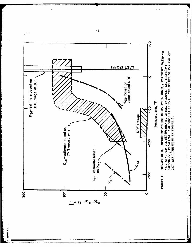
Figure 1. Summary of KId Measurements for Hy-80 Steeland KId Estimates Based on KIc, CVN, andDTE Measurements, Atter, Shoemaker andRolfe(24), Barson(25), Puzak(26), and Goodeet al(27). The Source of CVN and NDT Dataare Identified in Figure 2 ...... ................ 8
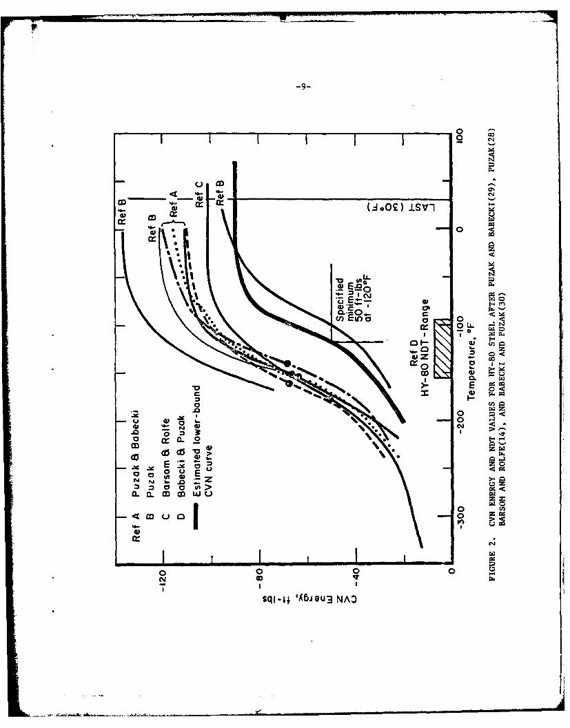
Figure 2. CVN Energy and NDT Values for Hy-80 Steelafter Puzak and Babecki(29), Puzak(28),Barsom and Rolfe(14), and Babecki and Puzak(30) .... 9
Figure 3. Summary of KId Measurements for Hy-130 Steel andKId Estimates Based on KIc, CVN and DTEMeasurements, Atter, Shoemaker and Rolfe(24),Barsom(25) and Pense(31), and Puzak(32) .......... .. 11
Figure 4. CVN Energy Values for Hy-130 Steel Plates inthe "Weak" (WR) Orientation After Puzak(32) ....... .12
Figure 5. DTE Energy Values for the Hy-130 Steel Platesof Different Thicknesses after Puzak(32). The1 In., 1.5 In., 2 In., and 2.5In. DTE ValuesHave Been Reduced by Factors of 8, 15, 22.6,and 29 to make Them Comparable to 5/8 In. DTEValues. The Estimated NDT Temperature areObtained by Relating it to the TemperatureCorresponding to a 5/8 In. DTE of 100 Ft Lbs(19). . . . 13
Figure 6. Correlation between Corresponding CVN and 5/8 In.DTE Values Measured on the Ductile shelf for theHy-130 Steels [Data of Figures 4 and 5 afterPuzak(32)]. The Scatterband Reflects the Approxi-mate Nature of the CVN DTE Correlation and Indicatesthat a DTE Value as Low as 300 Ft Lbs is Possiblefor a CVN of 60 Ft Lbs ....... ................. 14
Figure 7. Lower Bound (in Terms of Toughness) 1 In.,- DTE
Curves from a Limited Sampling of Mil-11018Welds Produced by the Portsmouth and NSRDC-AFacilities after Pellini(33). The NDT Estimatesare Based on Correlation 8 (Table 1) .... .......... 16
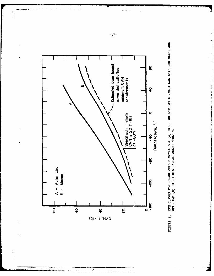
Figure 8. CVN Curves for Hy-80 Weld D Metal for (A) Mil-B-88Automatic Inert-Gas-Shielded Metal Arc Weld and(B) Mil-11018 Manual Weld Deposits .... .......... .17

LIST OF FIGURES
(Continued)
Page
Figure 9. Envelope of 2 In. DTE Values for Hy-130 TypeGMA Welds After Lange(34,35). The NDTEstimate is Based on Correlation 8 in Table 1 ..... .... 18
Figure A-1. Summary of Data Comparing the NRL DTE KIcCorrelation(10-13). Results for A533B AreFrom Reference 7 and 37 ...... ................ .A-2
Figure A-2. Proposed "Reference" Curves Relating KId andKim to the Temperature Relative to the NDTAfter Pellini(20) and Hahn et al(7) .... .......... A-3
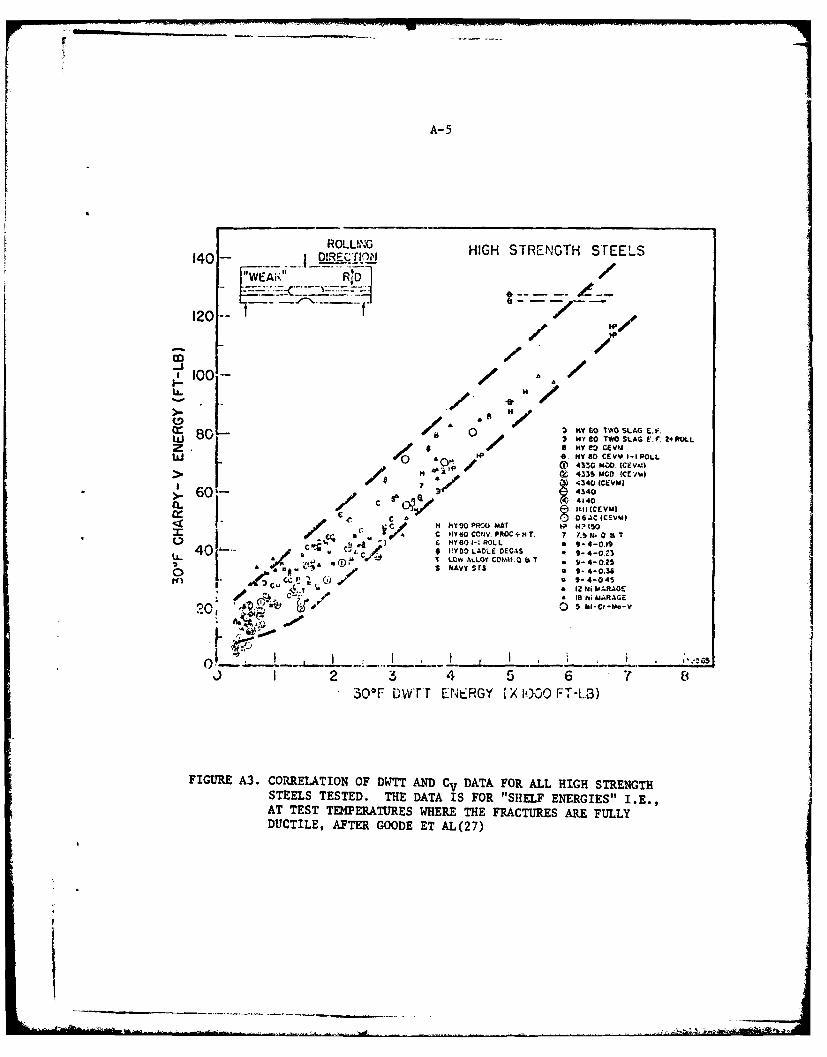
Figure A-3. Correlation of DWTT and CV Data for All HighStrength Steels Tested. The Data is for"Shelf Energies" i.e., at Test TemperaturesWhere the Fractures are Fully Ductile, afterGoode, et ai(27) ........ ................... A-5
Figure B-1. Schematic of the Structure of a Butt WeldAfter Pellini and Puzak(35) ..... .............. .B-2
Figure B-2. Explosion Test of Model Simulating Restraintof External Framing: Specimens and Weld JointDesign (Left); Configuration of Explosion TestDie (Right), and Observed Fracture Paths areIdentified in the Lower Section by the LetterA and B. The explosive was Detonated on theT-Frame Side of the Model. After Babecki andPuzak(36) .......... ....................... B-3
- . V

ABSTRACT
Lower bound dynamic fracture toughness parameters for HY-80 and
HY-130 steel and their weld metals are identified. Specific values of the
parameters KId and Klm obtained from direct measurements are reported to-
gether with estimates inferred from the large body of Charpy energy, nil
ductility transition temperature and dynamic tear energy measurements. The
emphasis is on resonable lower bound values at 300 F, the lowest anticipated
service temperature, for use in elastodynamic analyses of crack growth
initiation, propagation, and arrest in ship structures. For these conditions,
it has been found that the ratio KId/aY is approximately equal to 2 inches1/2
for HY-80 steel. For HY-130 steel and the HY-80 and Hy-130 weld metals under1/2
these same conditions, KId/aY is approximately 1 inch . Consequently, HY-
80 plate appears to be substantially more resistant to fracture under dynamic
loading than are the other three grades examined.

DYNAMIC FRACTURE TOUGHNESS PARAMETERS FORHY-80 AND HY-130 STEELS AND THEIR WELDMENTS
by
G. T. Hahn and M. F. Kanninen
INTRODUCTION
Applications of dynamic fracture mechanics to treat crack growth
initiation, unstable propagation, and arrest can now only be made in conditions
where an elastodynamic analysis is applicable. Successful analyses have al-
ready been made of impact experiments [1, 2], nuclear pressure vessels under
thermal shock conditions [3, 4] and gas transmission pipelines [5, 6]. How-
ever, the ability to perform an elastodynamic analysis alone is not enough
to obtain results of practical interest. Values of the materials's resistance
to crack propagation--the dynamic fracture toughness parameters--must also be
available. Unfortunately, for the tough ductile materials used in most
engineering structures, these values are not easy to obtain.
The work reported here is part of a larger effort aimed at providing
a basis for crack propagation analyses in flawed ship hulls subjected to shock
loading. Previous work in this program has shown that elastodynamically de-
rived stress intensity factors can be used to predict crack growth initiation
and propagation under impact loads [1]. Hence, while further development of
the approach is still needed--e.g., to take direct account of crack tip plas-
ticity--it is possible to provide preliminary estimates to evaluate ship hull
performance by coupling these analyses with the material toughness parameters
for the HY-grade steels. This report takes a first step toward the acquisition
of suitable values for such analyses by means of a literature survey of the
fracture properties of HY-80 and HY-130 and their weld metals.

-2-
BACKGROUND DISCUSSION
The analysis of crack growth initiation from a preexisting crack
in a structure and its subsequent rapid unstable propagation and arrest can
now only be effectively treated using elastodynamically determined stress
intensity factors. The stress intensity factor arises in the computed stress
field attending a crack tip. In general, it depends on time, the crack propa-
gation speed, the crack length, the external geometry of the cracked body, and
the applied loads. For a crack propagating in opening made conditions under
fixed external loading, an elastodynamic solution can generally be made, albeit
numerically, to determine the stress intensity factor in the form KI - K (tA)
where i denotes the instantaneous crack speed and t is time.
The criteria governing crack growth initiation and propagation can
be expressed in terms of KI and experimentally determined critical values that
are taken as material properties. First, for the onset of growth for a rapidly
loaded stationary crack
KI (t, o) -Kid (K) ()
where 6 denotes the time rate of change of the applied loading through the
consequent variation in the stress intensity factor. Like Kic, the conventional
fracture toughness, KId will also be a function of temperature. Of course, for
quasi-static loading, KId is identical with Kic.
The deformation state ahead of a propagating crack is generally dif-
ferent from that of a stationary crack. Consequently, the fracture property
associated with a moving crack will differ from one that is not. The criterion
for a rapidly propagating crack takes the form
KI (t, A) - K () (2)
where KID' in addition to being a function of temperature, is assigned a crack
speed-dependence to take account of the rate dependence. It is of some impor-
tance to recognize that the entire KID - KID (a) need not be known to perform

an effective calculation. The minimum value of this function at a given
temperature - conventionally designated as KIm - will suffice in many instances.
Equations (1) and (2), respectively, give quantitative criteria for
crack growth initiation and subsequent unstable propagation. A third such
relation is sometimes used for crack arrest which involves a statically com-
puted value of KI and an "arrest toughness" parameter KIa. However, while
this approach can be useful as an approximation in some conditions, it is not
logically correct. Within the context of an elastodynamic approach, crack
arrest will occur when Equation (2) can no longer be satisfied. That is, a
propagating crack will arrest at a time ta when KI > Klm for all t > ta
While it is true that under some conditions KIa is about equal to KIm,
it does not follow that such an approach is widely applicable. Rather, crack
arrest is properly viewed as the termination point of a general dynamic crack
propagation event for which the relevant fracture property is Klm.
Methods of measuring KId (K), KID (a), and Klm have been devised
and efforts to produce ASTM standards for these tests are underway 9 . How-
ever, very few measurements of this type have so far been performed on the
HY-80, HY-100 and HY-130 grades of steel and their weldments. The main reason
for this is that the high toughness values displayed by these materials at
service temperatures call for prohibitively large LEFM-type test pieces
The bulk of the evaluations performed by the NRL (Naval Research
Laboratory) and by industry rely on less costly measures of toughness: CVN-
(Charpy V-notch) energy, NDT-(Nil Ductility Transition) temperature and DTE
(Dynamic Tear Energy). These relative measures of toughness can be used to
obtain more-or-less approximate estimates of KIC, KId, and K m by way of a
number of empirical correlations identified in Table 1 and Appendix A. Of
these, the NRL DTE-K correlation, (Correlation No. 1 in Table 1) is probably
the most important because NRL relies on it to establish material toughness
requirements.
The logical extension of the ASTM E-399 fracture toughness test standardsize requirements to dynamic loading would call for the crack length andthickness requirement a, B > 2.5 (KId/Gyd)2 , where OYd is the dynamic yieldstress. Accordingly, a test piece about 20 in. x 20 in. x 10 in. is neededto measure shelf level toughness values, i.e., KId = 200 ksi /Tn of HY-80
steel (ayd 1 100 ksi rin).
I'. .. " '"

all -0.0 a 104 a a
09 -6 94 Ia C b r
2 ~ ~ 1 A m - -
A. s4
log -,UI-
- 44
0% -a WU

-5-
This report takes a first step toward defining the KId and Klm
values for the HY-80 and HY-130 steels and their weld metals appropriate
for dynamic LEFM analyses of submerged hull structures. The relative im-
portance of base metal, weld metal and HAZ (heat affected zone) is touched
on in Appendix B. The report surveys the limited number KId values obtained
from direct measurements, but draws the bulk of its KId and K estimates
from the larger body of CVN-, NDT-, and DTE-measurements. Since LEFM cal-
culations are likely to be concerned with "worst-case" conditions, the
emphasis is plased on reasonable, lower bound toughness values at the LAST
(lowest anticipated service temperature) which is 30* F for submerged shiphull
structure. These lower bound values are based on the specified minimum CVN-
and DTE-values listed in Table 2, and the trends displayed by representative
heats. In addition, the need for J and K measurements for base and weld
metals and further verification of the NRL-DTE-KIC correlation are identified.

00
o 0 0 0 0
0 M 0 M0 0
0 ' MC >.6 a~ 4- 41Le w t, SW 4 %
C C C
0 0 0 " o 0
4. 0 s
0 -- 0- i
k6.4 - 00 0 4.
0 Ln Lr
-A .- ,-nC- .C M
0 0 - 4J 4.L4.. ~.-o~i "4.3j
- .Uj
00 %0 .Nci CN C Ntj~~~C1 -C,.. , ,
0 '-4 -4 0 ~- U
V* 0o2 c IN3 N.
-0 P4 W (
4)> -4 0 a A-, -1 0u W2 4-0 W w & 6
00 0i w 0
&) 44r- 0ca wz1 cI a) 00 -4 ua 0I .1 a 4-4 -. 1 ;-4 -4 Sw$1.4 4
Iw CI I CL .6h
-C'-'Ni - .C n4

-7-
DYNAMIC FRACTURE TOUGHNESS PROPERTIES
HY-80 Base Plate
Existing direct measurements and estimates of KId (K1 10 5 ksi
i-T sec- ) derived from KIC-, CVN-, and DTE-measurements are summarized in
Figure 1. The CVN curves in Figure 2 illustrate that the NDT temperature
for this grade corresponds roughly with the midpoint of the CVN energy trans-
ition. An estimate of the lower bound, the curve LB, just satisfies the
specified minimum CVN value (50 ft lbs at -120* F) and reflects the likely
temperature variation.
The CVN curves and the KId values inferred form them in Figure 1
(of the Correlations 4 and 5 in Table 1), illustrate that HY-80 displays
ductile, upper shelf-level behavior at the LAST. The KId estimates at the
LAST are derived from CVN and DTE measurements (Correlations 3, 1, and 5 in
Table 1). No crack arrest toughness (Klm) measurements have so far been
performed on HY-80; the estimates in Table 3 are based on the highest NDT
temperature and the KIm reference curve in Figure A-2.aYd
HY-130 Base Plate
Direct measurements of K are produced in Figure 3, together withId
KId estimates based on Klc (Correlation 2), CVN (Correlation 4) and DTE
(Correlation 1). Representative CVN and DTE transition curves are reproduced
in Figures 4 and 5. These curves illustrate that HY-130 grade, like the
HY-80, displays ductile shelf behavior at the LAST.
The specified minimum CVN for this material (60 ft lbs at 300 F)
provides one basis for estimating the lower bound Kic and KId values. The
corresponding DTE provides another. Since the correlation between CVN and
DTE is approximate, it further reduces the lower bound value of DTE associated
with the LAST to 300 ft lbs. This is illustrated in Figure 6. No crack arrest
toughness measurements have so far been performed on HY-130 steel. The estimate
of KIm quoted in Table 3 are based on the KIm reference curve in Figure A-2.
Yd
4 . ,. ,~e .... -' , ,. -' " '. . " "
0
j z
___ _U0__ ( 12) ISV1lcn
C-
00
(n 0 mw
b..
06L
I ~aa)
0
04
0 0c7 , E
-9-1
0
cr I 0 Cr
-a)Ur Et-a
.4- an
aanPR
<4
070
.4~00 .
CD ~ XC.U
M p0-
0
00 0 0
* aa0 0 E
030
0 0 00
sqI-4; 'A~jsu3 NA:)
-10-
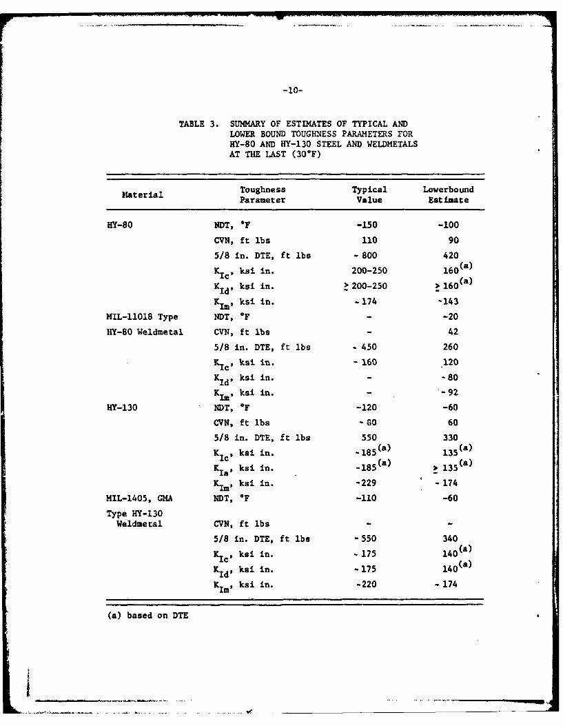
TABLE 3. SUMMARY OF ESTIMATES OF TYPICAL ANDLOWER BOUND TOUGHNESS PARAMETERS FORHY-80 AND HY-130 STEEL AND WELDMETALSAT THE LAST (300F)
Material Toughness Typical LowerboundParameter Value Est imate
HY-80 NDT, OF -150 -100
CVN, ft lbs 110 90
5/8 in. DTE, ft lbs - 800 420
KIc, ksi in. 200-250 160(a )
KId, ksi in. > 200-250 > 160 ( a )
Kim* ksi in. -174 -143
MIL-11018 Type NDT, OF - -20
HY-80 Weldmetal CVN, ft lbs - 42
5/8 in. DTE, ft lbs - 450 260
KC ksi in. - 160 120
Kd ksi in. - -80
K1m ksi in. - -92
HY-130 NDT, OF -120 -60
CVN, ft lbs - 80 60
5/8 in. DTE, ft lbs 550 330
KIc, ksi in. -18 5 (a) 135(a)K ia, ksi in. -185 ( a ) 135 ( a )
Klm, ksi in. -229 - 174
MIL-1405, GMA NDT, OF -110 -60
Type HY-130Weldmetal CVN, ft lbs
5/8 in. DTE, ft lbs -550 340
KIc, ksi in. - 175 140(a)
KId' ksi in. -175 140 (a )
K 1 , ksi in. -220 - 174
(a) based on DTE
_____.. ........... ._____

-11- IV-
LL c Z00
00
IE-
06
000.0 0
N N
00
0 -
!s 0 ;

Ii' -12-
to0 4 2 ~ HY 130 (T) Steel- 0000iii8
/0000J K79
0O
K2
.3t
0
80 "- 1~! HY 13 (T S *~'
1802
0O )teel
00G7
u 600
40 .
-80 -60 -40 -0 0 20 *CTernPerot ure
FIGURE 4. CVN ENERGY VALUES FOR HIY-130 STEEL PLATES IN THE 'tWEAKt,(WR) ORIENTATION AFTER PtTZAJ(32)

-13-1000
800/
0 010
200 P4
DTIISE curv
4 00 -0 0
TempeEstumated
Estiated NDUS HETTDT RanERAURe AR OBTAIE fro RE TI5
ITZA(TO) THE 1PRTR IN.,R1.5N,2IN.,T AD 5 IN. DTE OALUES HAV LBEEN9

-14-
1000 0 Base plate
* Weld plate
800
.00
I-) 000
400 -Estimated lower
80060s 100CVN, ft-lbs
FIGURE 6. CORRELATION BETWEEN CORRESPONDING CVN AND 5/8 IN. DTEVALUES MEASURED ON THE DUCTILE SHELF FOR THE HY-130STEELS [DATA OF FIGURES 4 AND 5 AFTER PUZAK(32)]. THESCATTERBAND REFLECTS THE APPROXIMATE NATURE OF THE CVNDTE CORRELATION AND INDICATES THAT A DTE VALUE MAYBE ASLOW AS 300 FT LBS FOR A CVN OF 60 FT LBS

-15-
Weld Metals
The most telling toughness evaluations of HY grade weld metal--
weld metal and HAZ--are obtained using the explosion bulge test
While this is a very severe test of performance, it has not been correlated
with absolute measures of toughness like Kic or Kid. The only direct LEF14-
type tests are the few measurements of the COD for a HY-130 plate and HAZ(31)that have recently been reported by Pense These are converted to KId
estimates in Figure 3 (Correlation 13). Estimates of Kd must be drawn
from the body of CVN and DTE measurements of weld metal which have been
developed by NRL. These studies show that, while HY-80 and HY-130 display
near ductile shelf-level behavior on the average, some lower bound values
fall in the transition range.
Figure 7 reproduces lower bound 1 inch DTE curves from a limited
sampling of welds produced by the Portsmouth and NSRDC-A facilities. This
set of results shows that the lowest value at the LAST is 260 ft lbs (5/8
inch DTE) for a vertical position weld. The CVN curves for this class of
weld metal, shown in Figure 8, indicate a lower bound CVN value of 42 ft lbs
at the LAST for weldment just meeting the 20 ft lbs at -60* F minimum speci-
ficatio Figure A-3 indicates that 42 ft lbs (CVN) corresponds with about
2000 ft a inches, 1 inch DTE, or 250 ft lbs -5/8 inch DTE. This is in agree-
ment with the 260 ft lb value mentioned above. Corresponding KId estimates
are listed in Table 3. The Kim value is based on the NDT estimate of Figure
7 and the KILlaYd reference curve of Figure A-2.
Results for a large number of HY-130 welds of the Mil-140S weld
metal GMA type are summarized in Figure 9. The lower bound is an indication
of the poorest quality encountered in practice. These results are for 2 inch
DT specimens. Estimates of the corresponding 5/8 inch DT behavior are obtained
by shifting the curve about 40* F( 3 3 ) and reducing the energy by a factor of
22.6. These results suggest a lower bound of 340 ft lbs 5/8 inch DTE at the
LAST and a maximum NDT temperature of about -600 F. The 340 ft lbs value is
significantly lower than 500 ft lbs @ 300 F specified minimum for this type
of weld metal (see Table 2). The corresponding KId estimate (Correlation 1)
and Kim estimate (Figure A-2) are listed in Table 3.
_ _ _

oc
E-4
4)~-h o 0E. O
0 000
00
0 0~0 0
.ql -4 610 ul0
-17-
C 002n 0
00&4
IE 0
\ E-
EE
00
ul 0
0> 06 0
.9 <
Eq- 00N-40U
0L

-18-
800
0NDT- estimated
700
15,000
600
500 W
400
CD 4b
U') 3000
200 5000
200
-120 -80 -40 0 40 80 120 160Temperature, *F
FIGURE 9. ENVELOPE OF 2 IN. DTE VALUES FOR HY-O TYPE GMA WELDSAFTER LANGE(34,35). THE NDT ESTIATE IS BASED ONCORRELATION 8 IN TABLE 1

-19-
DISCUSSION OF FINDINGS
The lower bound KId values for the HY-CO and HY-130 steel and weld
metals, listed in Table 3, tend to fall short of the toughness levels of
200 MPam - 300 MPam / 2 that are usually associated with ductile, shelf-
level performance. This may be a consequence of the lack of direct measure-
ments for these materials near the LAST, which forces reliance on approximate
(and possibly conservative) DTE and CVN correlations, whose precision for HY-
grades and steels under high toughness levels is not well established. Some
indication of the uncertainty connected with the NRL-DTE-Kc correlation can
be found in Appendix A.
Where minimum toughness levels are specified in terms of CVN-values,
the approximate nature of the CVN-DTE correlation tends to reduce lower bound
estimates of K via DTE even further. The K estimates in Table 3 areId Im
particularly uncertain and speculative. No KIm measurements are available
for HY-grades that can be used to test the reference curve procedure. In
addition, the K estimates do not reflect the rising resistance to fractureId
with crack extension (R-curve behavior). The positive K-dependence, which
adds significantly to load carrying capacity when such extension proceeds
with shelf-level toughness values, is also not included. Finally, the present
lower bound estimates were obtained without: (i) the precise criteria, (ii)
the statistical treatments of the data, and, in some cases, (iii) the sufficiently
large data base, which is essential for critical structural analyses.
Bearing those limitations in mind, it is still instructive to note
that approximate lower bound values of KId/aY are 2vi'Tn. for HY-80 steel and
liin. for HY-130 steel and the two weld metals. The 2rin. KId/a Y value indi-
cates that a 4 inch thick plate of HY-80 satisfies the (YC) criterion (essen-
tially, leak-before-break at general yield), while a lrin. value indicates
this criterion is only satisfied by HY-130 and the two weldments for 1 inch
thick plate. It would therefore appear that the HY-80 plate is substantially
more resistant to fracture under dynamic loading than the other three material
grades.

-20-
The reliability of future calculatuions of hull-structure fracture
behavior under dynamic loading will be enhan'ced by a better resolution of
the K and K toughness parameters. This will require direct measures ofId Im
K and K that can be used to calibrate D1!E and CVN values at the LAST.Id IM
The task of measuring the very large K andi K values is now greatly re-SId iIm
duced because KIc values can be derived from; J measurements. These measure-
ments use small test pieces under an ASTM prbcedure which is close to stand-
ardization. Since shelf level K values ari likely to be 15-25% larger thanId
K Ic*, JIc values also offer lower bound estimates of KId .
More research is needed to define Fhe KI dependence of these values,
but this should not be a formidable problem. i Crack arrest Loughness values
can also be obtained from J sc Since KIm KI on the shelf. Finally, JIc
determinations can be combined with measuremEnts of the R-curve which offer
the possibility of describing stable growth and instability in addition to
the onset of crack extension. For weld metal' the existing test procedures1/ 151sli. / 2 i h
make it possible to measure 100 ksi in.1/2 ! 150 ksi in. in the
transition range. Such measurements are needed to establish the reliability
of a KIM reference curve based on NDT or other procedures for estimating KiIm
from more easily measured properties.
Compare shelf-level CVN values for staltistically and dynamically loadedspecimens in Reference (14).
i!

-21-
CONCLUSIONS
A survey of dynamic fracture toughness properties suitable for
analyses of crack propagation in submerged ship hulls has been conducted.
This survey has concentrated on HY-80 and HY-130 steels and their weld metals
at 30* F, the lowest anticipated service temperature (LAST) for these materials.
The key findings of the survey are:
1. The HY-80 and HY-130 grades satisfying specified minimum
toughness requirements display ductile, shelf-level behavior
at the LAST. Weld metals of these grades satisfying minimum
toughness requirements operate closer to the lower part of the
transition region.
2. A lower bound value of the ratio K /a is estimated to be
1/2 Id Y2 inches for HY-80 at the LAST. For HY-130 and both the
HY-80 and HY-130 weld metals, a lower bound value of this
ratio is about 1 inch / 2*. It appears from these figures that
HY-80 steel is substantially more resistant to fracture under
dynamic loading than are the other three grades examined.
3. Lower bound KId estimates in Table 3 may underestimate the
toughness of the HY-steels and weld metals because of the
dearth of direct measurements of these quantities and consequent
uncertainties in the correlations on which the estimates are
based. Lower bound estimates of the crack arrest toughness,
K M in Table 3 are particularly uncertain and speculative be-
cause no measurements of this quantity are available for any
HY-grades. Direct measurements of KId and Klm are
teasible and should be attempted.
It can be concluded that criteria for "worst-case" lower bound toughness values
should be established. These should be applied to statistical treatments of
the measurements to improve the definition of lower bound toughness values.
This value is based upon plate purchase to a CVN-60 ft-lb requirement
and the CVN-DT Correlation in Figures 6 and A3. If the optional DTE
500 ft-lb at 0°F requirement is used, the minimum KId/ay ratio for theplate would be 1.6 which is close to a general yield condition for
2 in.-plate.
D

-22-
Also, measurements of shelf value JIC and JR curves should be performed with
the aim of improving and validating the NRL DTE-K correlation and to provide
more reliable, lower bound estimates of KId and K l. Finally, the crack arrest
toughness properties of weld metals with toughness levels close to the specified
minimum should be measured at the LAST with the aim of establishing a suitable
estimation scheme.

-23-
REFERENCES
(11 Mall, S., Kohayashi, A. S., and Urabe, Y., "Dynamic Photoelasticand Dynamic Finite Element Analysis of Polycarbonate Dynamic TearTest Specimens", ASTM STP (To be published)
[2] Kobayashi, A. S., Seo, K., Jou, J. Y., and Urabe, Y., "DynamicAnalyses of Homalite-100 and Polycarbonate Modified Compact-TensionSpecimens", Technical Report No. 35 or ONR Contract N00014-76-C-0060NR 064-478, March, 1979.
[3] Cheverton, R. D., Iskander, S. K., Gehlen, P. C., and Hahn, G. T.,"Application of Crack Arrest Theory to a Thermal Shock Experiment,ASTM STP, (To be published).
[4] Hahn, G. T., Hoagland, R. G., Leveim, J., Markworth, A. J., andRosenfield, A. R., "Fast Fracture and Crack Arrest Toughness ofReactor Pressure Vessel" ASTM STP (To be published).
[5] Kanninen, M. F., "A Critical Appraisal of Solution Techniques inDynamic Fracture Mechanics", Numerical Methods in Fracture MechanicsA. R. Luxmoore and D. R. J. Owen Eds. Univ. College Swansea, 1978,p. 612.
[6] Popelar, C., Rosenfield, Kanninen, M. F., Pressure Vessel Tech.,Vol. 99, p 112, 1977.
[7] Hoagland, R. G., Rosenfiled, A. R., Gehlen, P. C., and Hahn, G. T.,"A Crack Arrest Measuring Procedure for KIm, KID, and KIA PropertiesASTM STP 627, p 177, 1977.
(8] Crosley, P. B., Ripling, E. J., "Toward Development of a StandardTest for Measuring KIA", ASTM STP 627, p 372, 1977.
[9] Minutes of the Meetings of the ASTM Task Group, E-24.01.06 on Kidand KIa Testing.
110] Low, J. R., Jr., et al, "Rapid Inexpensive Tests for DeterminingFracture Toughness, NMATS, 1976.
(11] Judy, R. W., Jr., Freed, C. N., and Goode, R. J., "Characterizationof the Fracture Resistance of Thick Section Titanium Alloys", Proceed.Second Int. Conf. on Titanium Science and Technology, Vol. 2 p 1393,1973.
[12] Freed, C. N., and Goode, R. J., "Correlation of Two Fracture ToughnessTests for Titanium and Ferrous Alloys, NRL Report 6740, 1969.

-24-
[13] Freed, C. N., Goode, R. H., and Judy, R. W., Jr., "Comparison ofFracture Toughness Test Procedures for Aluminum Alloys", Eng'gFract. Mech., Vol. 2, p 359, 1971.
[14] Baosom, J. M., and Rolte, S. T., "Correlation Between KIc andCharpy V-Notch Test Results in the Transition-Temperature Range",ASTM STP-466, p 281, 1970.
(15] Barson, J. M., Development of the AASHTD Fracture Toughness Re-quirements for Bridge Steels, Eng'g. Fracture Mech., Vol. 7, p 605,1975.
[16] Marandet, B., and Sanz, G., Evaluation of the Toughness of ThickMedium Strength Steels by Using Linear Elastic Fracture Mechanics andCorrelations Between KIc and CVN, ASTM STP, 1977.
[17] Irwin, G. R., "Linear Fracture Mechanics, Fracture Transition, andFracture Control", Eng'g. Fract. Mech., Vol. 1, p 241, 1968.
[18] Pellini, W. S., "Advances in Fracture Toughness CharacterizationProcedures and in Quantitative Interpretations to Fracture-Safe Designfor Fracturesafe Design for Structural Steels, NRL Report 6713, Apr.,1968.
[19] Lange, E. A., "Dynamic Fracture Resistance Testing and Methods forStructural Analysis, NRL Report 7979, Apr., 1976.
[20] Pellini, W. S., "Introduction to AAR Guidelines for Fracture-SafeDesign Involving Temperature-Transition Sensitive Steels", Report toAAR on Project No. H-0Ol, Apr., 1979.
[21] Rice, J. R., "A Path Independent Integral and the Approximate Analysisof Strain Concentration by Notches and Cracks", J. App. Mech., Vol. 35,p 379, 1968.
[22] Hahn, G. T. (Unpublished work)
[231 Rice, J. R., and Johnson, M. A., "The Role of Large Crack Tip GeometryChanges in Plane Strain Fracture", Inelastic Behavior of Solids, ed.M. F. Kanninen, et al, McGraw Hill, p 641, 1970.
[24] Shoemaker, A. K., Rolfe, S. T., "The Static and Dynamic Low-TemperatureCrack-Toughness Performance of Seven Structural Steels", Eng'g. Fract.Mech., Vol. 2, p 319, 1971.
[251 Barsom, J. M., "Relationship Between Plane Strain Ductility and KIcfor Various Steels", Paper No. 71-PVP-13, ist National Congress onPressure Vessels on Piping, San Francisco, 1971.
A -
-25-
[26] Puzak, P. P., "Comments and Justifications for Proposed Changes forMIL-S-16216H (SHIPS), NRL Memo, 31 July, 1971.
[271 Goode, R. J., Huber, R. W., Howe, D. G., Judy, R. W., Jr., Puzak,P. P., Lloyd, K. B., Crooker, T. W., Morey, R. E., Lange, E. A., andFreed, C. W., "Metallurgical Characteristics of High Strength Struc-tural Materials NRL Report 6405, Nov., 1965.
(28] Puzak, P. P., "Explosion-Bulge Test Performance of Machine Welded1-inch thick HY-80 Steel, NRL Memo Report 691, Apr. 1957.
[29] Puzak, P. P. and Babecki, A. J., Explosion Bulge Test Performance ofHY-80 Weldments, NRL Memo Report 878, Dec., 1958.
[30] Babecki, A. J., and Puzak, P. P., "Notch Toughness Evaluations ofModified HY-80 Steel in Heavy Gauge Plates, NRL Memo Report 995,Dec., 1959.
[31] Pense, A. W., "Fracture Toughness of Bridge Steels, Phase III Report:State of the Art of Fracture Toughness Testing of Weldments", ReportFHWA-RD-760-109, Aug., 1973.
[32] Puzak, P. P., "Summary of Transition Temperature Data for the HY-130Steel Weldment System", NRL Memorandum Report 2154, July, 1970.
(331 Pellini, W. S., Summary of DT Test Data for HY-130/140 Welds and11018 Welds, NRL Memo, 5 April, 1973.
[34] Lange, E. A., Characterization of 2-In., HY-130 Welds, NRL ProgramReport, Mid. FY 1976, 27, 29, Jan., 1976.
(35] Lange, E. A., Characterization of 2-In. Thick HY-130 Welds, NRL ProgramReport, FY-76 and FY-Q, 2 Dec., 1976.
[36] Pellium, W. S., and Puzak, P. P., "Factors that Determine the Applica-bility of High Strength Quenched and Tempered Steels to Submarine HullConstruction, NRL Report 5892, Dec. 5, 1962.
(37] Babecki, A. J., and Puzak, P. D., Explosion Test Performance of Small-Scale Submarine Hull Weldments, NRL Memorandum Report 996, Dec. 1959.
[38] Loss, F. J., and Pellium, "Dynamic Teat Test Defini.ion of the Temper-ature Transition from Linear Elastic to Gross Strain Fracture Condi-tions", NRL Report 6787, Nov. 1968.

APPENDIX A
CORRELATIONS BETWEEN FRACTURE TOUGHNESSPARAMETERS AND DTE, NDT, AND CVN

I
APPENDIX A
CORRELATIONS BETWEEN FRACTURE TOUGHNESSPARAMETERS AND DTE, NDT, AND CVN
The reliability of different correlations between LEFM fracture
toughness parameters and DTE, NDT, and CVN values is examined in detail in
Reference 10. Some points, which are not treated in that reference, but
are important in the context of this report are discussed below.
Correlations with DTE
The data, which were used to construct the NRL DTE-K correlationIC
are identified in Figure A-1. Relatively few measurements were originally
performed on medium strength steels in the transition range. The KId portion
of the curve was constructed later, and is based on DTE values at the NDT,
and the assumed relation KId - 0.5 in. , which is approximate. The
curve for the A533B steel is based on 5/8 in.-DTE measurements performed atNRL [371', and Kic measurements on a number of (different) heats of [533B in
Reference 7. The Kic values predicted by the A533B curve are about 20-30%
smaller than the one obtained from the NRL curve. To be conservative, the
A533B curve is used to estimate KIc and KId values on this report.
Correlation with NDT
The concept of indexing the toughness transition curve to the NDI
temperature, which has been championed by Pellini, is widely used. Recently,
Pellini has proposed a KId reference curve for medium strength steels indexed
to the NDTL 2 . Pellini's curve relates the absolute toughness, KId, to the
relative temperature (T-TNDT). Since the fracture toughness at the NDT-
temperature is believed to vary with yield strength [18 ], an attempt has been
made here to make it more general by expressing the relation in terms of K Id/aYd
with the value of this ratio (K /a )NDT - 0.6/Tn. The resulting referenceId Yd
curve is shown in Figure A-2. Estimates of K based on the upper bound NDIId

A-2
88
0 P."
fN v
v v-4
c (0U 0p- a, '0.- =-o a>vn- u
* E-? h.." o t o too x o .
I\\ \ 'I', =.
U 0 0
Ill. _ -- 0 E
I II - - , g .~I .U:
w
.... ,. . -.- -
0 0 \, ,,I ~~~* I w-Js s"..
Pd
0No
o 0
00
' lPI 1 $XI

A- 3
KId
O"Yd2
~KIbm
~0YY
0 100 200
(T-T NDT), OF
FIGURE A2. PROPOSED "REFERENCE" CLRVES REATING KId AND KIm TO THETDIPERATURE RELATIVE TO THE NDT AFTER PELLINI (20) ANDHAHN ET A.L(7)

A-4
and obtained in this way are included in Figures 1 and 3. The same reasoning
has been used to generalize Kla measurements performed on A533B [7 ]. The
Klm/TYd reference curve shown in Figure A-2 is based on K values one stan-Im Yd (7] I
dard deviations below the average . It should be noted that while this
method of estimating K m is unproven, and speculative, it is the only approach
currently available for estimating crack arrest toughness values.
Estimates of ayd were obtained using the approximation yd +
25 ksi, where a is the conventional yield stress and a is the yield stressY03 -1 Yd
for rates of straining ep - 10 sec
Correlation with CVN
A correlation between shelf level CVN and DTE values developed at
NRL [2 7 ] is reproduced in Figure A-3.
L_
A-5
RLG HIGH STRENGTH STEELS
~f*'03 KV DOTWO SLAG E.FNY400 TWO SLAG E FPOLL
a0.ImysoC H4 Y0 CE VM.0 i POLL(o) 4330 MO. CEYM)* 4335 MOD ~~I
V~ 4340
> . 60,414
C~Q 6 AC (CEVMi)Ygo PROU MAT ~ ~ 8
A c N-0)I-: POLL * 9-4-0.S4 c -i T.0 LADLE EAS - 9- 4-0.23
I L~# ALOY CMM. b 9-4-0.25> A, 9-4-0.3.S kA r 9-4-045pri
* 2 Ns M.6RAGE
IS lBi. MARAGE
2040 5 - fMOO {¢ ','W
.0 GS,,
2 3 ( 7 63 0 F uwrr ENERGY (X l30 FiT-t-3)
FIGURE A3. CORRELATION OF DWTT AND CV DATA FOR ALL HIGH STRENGTHSTEELS TESTED. THE DATA IS FOR "SHELF ENERGIES" I.E.,AT TEST TEMPERATURES WHERE THE FRACTURES ARE FULLYDUCTILE, AFTER GOODE ET AL(27)
APPENDIX B
WELD STRUCTURE

APPENDIX B
WELD STRUCTURE
The toughness of the HAZ (Heat Affected Zone) of a weld (B-i) can
be lower than that of the base metal or the weld metal (see Figure B-i).
However, because the HAZ is usually narrow, and the weld tapered, a crack
initiated in the HAZ of the butt weld will tend to propagate into the base
metal or the weld metal. Examples of this for a T-frame attachment are
illustrated in Figure B-2. Explosion bulge tests provide further verification
that the HAZ does not provide an easy path for a fracture. These considerations
provide justification for focusing on the base metal and the weld metal and
neglecting the HAZ in lower bound toughness assessments of welded structure.

Ternper ing/
Iracedl placed
Hardness
0600 I
2500
.300
200
FIGURE B1. SCHEMATIC OF THE STRUCTURE OF A BUTT WELD AFTERPELLINI AND PUZAK(35)

B-3
II DIRECTION
OFROLL II
" I, II
III
I I
FRAMING: SPECIMENS AND WELD JOINT DESIGN (LEFT); CON-FIGURATGR O EXPLOION OF MDL TEST DIE (RIGRT), AND OBSERVED
FRACTURE PATHS ARE IDENTIFIED IN THE LOWER SECTION BY THELETTER A AND B. THE EXPLOSIVE WAS DETONATED ON THE T-FRAMESIDE OF THE MODEL. AFTER BABECKI AND PUZAK(36)


