Center for Sustainable Engineering of Geological and Infrastructure Materials (SEGIM)
Department of Civil and Environmental Engineering
McCormick School of Engineering and Applied Science
Evanston, Illinois 60208, USA
LATTICE DISCRETE PARTICLE MODEL (LDPM) FOR
PRESSURE-DEPENDENT INELASTICITY IN GRANULAR ROCKS
Shiva Esna Ashari, Giuseppe Buscarnera, Gianluca Cusatis
SEGIM INTERNAL REPORT No. 16-02/478L
Submitted to International Journal of Rock Mechanics and Mining Sciences February 2016

Lattice Discrete Particle Model (LDPM) forpressure-dependent inelasticity in granular rocks
S. Esna Asharia, G. Buscarneraa,ú, G. Cusatisa
aNorthwestern University, Department of Civil and Environmental Engineering, USA
Abstract
This paper deals with the formulation, calibration, and validation of a Lattice Discrete Particle Model
(LDPM) for the simulation of the pressure-dependent inelastic response of granular rocks. LDPM is
formulated in the framework of discrete mechanics and it simulates the heterogeneous deformation of
cemented granular systems by means of discrete compatibility/equilibrium equations defined at the grain
scale. A numerical strategy is proposed to generate a realistic microstructure based on the actual grain
size distribution of a sandstone and the capabilities of the method are illustrated with reference to the
particular case of Bleurswiller sandstone, i.e. a granular rock that has been extensively studied at the
laboratory scale. LDPM micromechanical parameters are calibrated based on evidences from triaxial
experiments, such as hydrostatic compression, brittle failure at low confinement and plastic behavior at
high confinement. Results show that LDPM allows exploring the e�ect of fine-scale heterogeneity on the
inelastic response of rock cores, achieving excellent quantitative performance across a wide range of stress
conditions. In addition, LDPM simulations demonstrate its capability of capturing di�erent modes of
strain localization within a unified mechanical framework, which makes this approach applicable for a
wide variety of geomechanical settings. Such promising performance suggests that LDPM may constitute
a viable alternative to existing discrete numerical methods for granular rocks, as well as a versatile tool for
the interpretation of their complex deformation/failure patterns and for the development of continuum
models capturing the e�ect of micro-scale heterogeneity.
Keywords: Granular sandstone, Discrete lattice model, Strain localization
1. Introduction
Granular rocks display complex mechanical properties, such as the transition from brittle to ductile
response upon increasing confinement [1], the tendency to dilate or contract upon shearing [2, 3], and the
formation of a wide range of strain localization mechanisms [4–6]. Such rich variety of deformation modes
depends on the inelastic properties of rocks, and it is invariably controlled by the confining pressure. For
example, while localized dilatant faulting is typically observed at low confinements, delocalized shear-
enhanced compaction often characterizes the deformation response at high pressures. The transition
from one type of response to another is typically gradual [1] and poses considerable challenges due to the
úCorresponding author
Email addresses: [email protected] (S. Esna Ashari), [email protected] (G.
Buscarnera), [email protected] (G. Cusatis)
Preprint submitted to International Journal of Rock Mechanics and Mining Sciences
competition of the microscopic processes that characterize each of the two aforementioned macroscopic
phenomena. This intermediate behavior has been found to be crucial for a variety of applications,
including the tectonics of faulting [7–9], the coupling between strain localization and fluid flow [10, 11],
reservoir compaction [12, 13] and borehole instability [14, 15].
In the brittle faulting regime, the onset of dilatancy is associated with the propagation of cracks that
align along directions subparallel to the maximum compressive stress. The coalescence of these cracks,
as well as the frictional interaction between fractured and unfractured zones, ultimately lead to the onset
of persistent shear bands, as well as to changes in physical properties, such as sti�ness, permeability, and
electrical conductivity [16, 17]. In the cataclastic flow regime, grain crushing and pore collapse dominates
the deformation process, ultimately leading to extensive densification of the rock mass. In high-porosity
rocks, such micro-mechanical processes have been found to promote compaction bands, i.e. modes of
strain localization characterized by the accumulation of compressive strains into narrow zones [18, 19].
While these compaction localization processes are induced by a local loss of strength, the rearrangement
of crushed fragments and the reduction of the local porosity often lead to a gradual transition to a
delocalized mode of deformation [20]. As a result, unlike single shear bands, multiple compaction zones
may propagate across the sample until a complete re-hardening of the specimen is observed [21].
The prevalence of a specific form of microscopic damage depends on the microstructural attributes of a
rock (e.g., grain size and sorting porosity; degree of cementation), as well as by its inherent heterogeneity.
Discrete mechanical methods are therefore convenient tools to accommodate grain-scale attributes and
explain their impact on the macroscopic deformation of rock cores. For example, the discrete element
method (DEM) has proved to be an e�ective tool for simulating the micromechanics of unconsolidated
materials, such as soil, sediment and fault gouge [22–25]. DEM represents the material as an assemblage
of independent particles interacting through forces computed on the basis of frictional contact models.
Such methods have often been adapted to the case of lithified geomaterials by incorporating inter-particle
bonds accounting for the presence of cementation, thus mimicking the nucleation of cracks though the
brittle failure of cohesive cement bridges [26, 27]. Such enhancements have enabled DEM to simulate
complex processes such as the development of shear bands and brittle fracturing [28, 29].
Nevertheless, standard DEM techniques based on spherical particles tend to produce unrealistically ratios
of uniaxial compressive to tensile strength [30], thus hampering the satisfactory prediction of the failure
characteristics of granular rocks deformed in the brittle faulting regime. Although this problem can
be mitigated by increasing the density of bonds between particles [29, 31] or by magnifying the grain
interlocking through irregularly shaped particles [32, 33], the ability to capture the full spectrum of tensile
and/or compressive failure mechanisms through a unified framework still represents a major challenge.
Similar limitations exist also for simulations in the high-pressure regime, where DEM analyses are often
used in conjunction with computationally intensive particle replacement schemes mimicking the e�ect of
grain crushing [34]. While these approaches have provided insights into the interpretation of compaction
localization, they often involve an unrealistic loss of grain mass, thus preventing a realistic simulation of
crushing-induced hardening upon hydrostatic compression [1].
To tackle these problems, this paper proposes an alternative discrete method that, by relying on a direct
2

representation of the microstructure, aims to accommodate a wide range of inelastic mechanisms i.e., it
enables accounting simultaneously for brittle/dilative modes of failure, as well as for the plastic regime
of compactive deformation. The proposed approach builds upon the so-called Lattice Discrete Particle
Model (LDPM), successfully developed by Cusatis and coworkers [35, 36] for the simulation of failure
processes in quasi-brittle solids such as concrete. A noticeable feature of LDPM is its ability to simulate a
granular microstructure through a system of polyhedral particles connected through a three-dimensional
lattice. Such particles can be placed randomly across the volume in accordance with a prescribed grain
size distribution, thus enabling the direct representation of a heterogeneous system of grains surrounded
by a bonding agent (e.g., mortar in concrete or mineral precipitants in natural rocks). At variance
with DEM techniques, the kinematics of the skeleton is modeled on the basis of the displacements and
rotations computed at the nodes of the lattice, thus enabling the computation of strain components
oriented normally and/or tangentially to the facets between the polyhedral particles. Such hypotheses
imply the use of an internal kinematics substantially di�erent from that of DEM. This facilitates the
use of more sophisticated constitutive laws to model the forces transferred among adjacent particles.
Recent works have demonstrated the ability of this approach to reproduce various aspects of quasi-brittle
behavior, such as fracture initiation and propagation, shear banding, and frictional processes [37–40].
Therefore, LDPM o�ers a convenient platform to simulate the mechanics of sandstones, a particular
class of quasi-brittle solids for which the pressure-dependent inelastic properties are primarily controlled
by the heterogeneity of their grain skeleton. Although the strategy discussed hereinafter is in principle
applicable to the analysis of any type of granular rock, here its capabilities are discussed for the particular
case of Bleurswiller sandstone, that is a high-porosity rock extensively studied in the literature and for
which a wide range of strain localization mechanisms have been documented [41, 42].
2. Grain generation
The strategy adopted in LDPM to replicate the grain-scale heterogeneity of sandstones is schematically
depicted in Figure 1, which illustrates through a simplified two-dimensional representation the basic steps
required to map the real microstructure of a granular rock into its numerical analogue.
As the grains in sandstones tend to be closely packed and in direct contact with each other (Figure 1a),
the isolation of cement bridges and grains is not straightforward. Therefore, a reasonable simplification
to discretize the domain into cement-coated grains having the same size distribution of the actual grains
can be obtained by hypothesizing that the granular lattice controlling the micro-mechanical interactions
is only secondarily a�ected by the geometry of the cement bridges. From a modeling standpoint, this
choice implies that the contribution of the cementing phase will not be modeled explicitly, but it will
rather be embedded implicitly into the particle-scale constitutive laws controlling the interaction between
skeletal grains.
In LDPM, the geometrical characterization of the mesostructure of sandstones is constructed by means
of an artificial supporting system based on spherical particles placed at the center of sandstone grains
(Figure 1b). Such a supporting system is generated by following a strategy similar to that proposed by
Cusatis et al. [35] for the case of concrete, i.e. by defining the size distribution of the spherical supports
3

eN
eLeM
σ
e
a b c
d e f
Grain Size (microns)150 200 250 300
Perc
ent F
iner
0
20
40
60
80
100 Dmin
DmaxLDPM facet
Figure 1: (a) Microstructure of a sandstone. (b) Artificial supporting system for grain generation. (c) 2D representation
of Delaunay tetrahedralization for the supporting system. (d) 2D representation of a polyhedral cell. (e) A 3D polyhedral
cell/a LDPM cement-coated grain. (f) Grain size distribution of Bleurswiller sandstone used for the LDPM simulations.
through a probability density function (pdf) defined as follows:
f(d) = qdq0
[1 ≠ (d0/da)q]dq+1 (1)
which is associated with a sieve curve in the form:
F (d) =1 d
da
2nF
(2)
where d0 is the minimum particle size, da is the maximum particle size, q is a material parameter and
nF = 3≠q is the sieve curve exponent. The volume fraction of simulated particles (‹a0) can be calculated
as:
‹a0 = [1 ≠ F (d0)]‹a = [1 ≠1d0
da
2nF
]‹a (3)
where ‹a is the particle volume fraction per unit volume of sandstone and the total volume of simulated
particles is Va0 = ‹a0V , if V is the volume of the domain of interest. It should be noted that for each
sandstone, d0, da, nF and ‹a should be calibrated based on measured grain size distribution of the rock.
In this approach, the particle diameters di are computed by sampling the cumulative distribution func-
tion (cdf) associated with Equation (2) by means of a random number generator [35]. New particles are
generated until the total volume of generated spherical particles ÂVa0 =q
i(fid3i /6), exceeds Va0.
After the stage of particle generation, the particles are randomly distributed across the specimen on
4

vertices, edges, surface faces, and interior volume. In order to have a statistically isotropic random
mesostructure, particle centers are placed throughout the volume of the specimen from the largest to the
smallest, preventing possible overlaps between the particles.
The next step is to define the topology of the grains of the modeled sandstone by using Delaunay tetra-
hedralization and a 3D tessellation. Through the Delaunay tetrahedralization, the nodal coordinates
of the particle centers are used to define a three-dimensional mesh of tetrahedra (Figure 1c). These
tetrahedra do not overlap, fill the entire volume of the specimen, and have vertices coinciding with the
given particle centers. The final geometry of the grains is defined by performing a 3D tessellation of the
domain anchored to the Delaunay tetrahedralization. For details on the adapted tessellation, the reader
is refereed to Ref. [35]. By collecting all the facets associated with one particle (Figure 1d), it is possible
to obtain a polyhedral cell representing a cement-coated grain (Figure 1e). The grain size distribution
of the simulated sandstone can eventually be expressed by computing the volume of each polyhedral cell
and plotting the statistical distribution of their volume-equivalent sphere diameters similar to Figure 1f.
It is worth noting that the iterative comparison between this synthetic grain size distribution and the
actual grading of the rock is pivotal to define the parameters (d0, da, nF , ‹a), which must in turn be
calibrated through a trial-and-error procedure specific for the selected rock.
3. LDPM constitutive equations
In LDPM, the grains interact with each other through the facets that connect them, and the displace-
ment field is defined through the rigid body kinematics of the grains. Similar to previous LDPM work
[35], the mechanics of grain interaction is formulated based on an analysis of an assemblage of four parti-
cles located at the vertices of a tetrahedron. The displacements and rotations of the nodes adjacent to a
facet can be used to compute the displacement jump [[uc]] at the centroid of each facet in the tetrahedron.
Such displacement jump is then used to define the strain components of the facet (Figure 1e):
eN = nT [[uc]]¸
; eL = lT [[uc]]¸
; eM = mT [[uc]]¸
(4)
where ¸ indicates the interparticle distance, n, l and m are unit vectors that define a local reference
system attached to each facet. Note that the displacement jump [[uc]] is defined such that positive normal
strain eN represents compression.
Prior to the initiation of micro-scale inelastic processes, the constitutive relation between the strain vector
e and the stress vector � at the facet level is incrementally elastic:
‡N = EN eN ; ‡L = –EN eL; ‡M = –EN eM (5)
where EN is the e�ective normal modulus, – is the shear-normal coupling parameter.
In LDPM, the reversible elastic behavior is limited by a number of nonlinear stress-strain boundaries,
each mimicking di�erent types of meso-scale inelastic phenomena that involve softening for pure tension
and shear-tension, as well as plastic hardening for pure compression and shear compression.
5

3.1. Pore collapse and material compaction
Under high-pressure hydrostatic compression, sandstones exhibit strain-hardening plasticity, which is
characterized by an initial phase of pores collapse and a later phase, in which the walls of completely
collapsed pores become in contact leading to a significant densification of the material. In terms of
stress strain response, the first phase is associated with a sudden decrease of the sti�ness yielding that is
later regained in the second phase (rehardening). LDPM simulates these phenomena through a strain-
dependent normal boundary (‡bc) limiting the compressive normal stress and it is assumed to be a
function of the local volumetric strain eV and deviatoric strain eD. The volumetric strain is computed
at the tetrahedron level as eV = (V ≠ V0)/V0, where V and V0 are the current and initial volume of the
tetrahedron, respectively. In each LDPM tetrahedron, all twelve facets are assumed to be subjected to
the same volumetric strain, whereas each facet is characterized by a di�erent value of the deviatoric strain
calculated by subtracting the volumetric strain from the normal strain: eD = eN ≠ eV . This definition
of local strains are equivalent to the ones used in typical microplane model formulations [43, 44]
For a constant deviatoric-to-volumetric strain ratio, rDV = eD/eV , the pre-yielding response, is assumed
to be characterized by an initial bilinear evolution modeling the closure of existing fissures. This stage
is followed by linear elastic response after the complete closure of the fissures (Figure 2a). The post-
yield response is assumed to be controlled by a linear plastic behavior modeling the initial stages of pore
collapse, then switching to an exponential form to model compaction-induced rehardening (Figure 2a).
The relations that simulate such sequence of compression processes is:
‡bc (eD, eV ) =
Y___]
___[
max(EN eN , —1EN eN ) 0 Æ eV Æ ec0 + ef
‡c0 + ÈeN ≠ (ec0 + ef )ÍHc (eV , eD) ec0 + ef Æ eN Æ ec1 + ef
‡c1 (rDV ) exp[(eN ≠ (ec1 + ef )) —2Hc (eV , eD) /‡c1 (rDV )] otherwise(6)
where —1 is the fissure closure parameter used to enforce the initial nonlinearity and ef is the normal
strain o�set associated with the fissure closures at which the typical linear elastic response commences. In
the present model, ef is assumed to be a function of ¸, the local interparticle distance, and w0, the average
size of fissure cracks openings in a sandstone: ef = w0/¸. The parameter ‡c0 is the meso-scale yielding
stress at the onset of pore collapse and ec0 + ef is the corresponding compaction strain; Hc (eV , eD) is
the initial hardening modulus, —2 the rehardening coe�cient, ec1 + ef the compaction strain at which
rehardening begins with ‡c1 (rDV ) = ‡c0 + (ec1 ≠ ec0)Hc (eV , eD) as the correlated stress. The hardening
modulus is formulated through Equation 7 which preserves the continuity of the slope for transition from
positive to negative deviatoric-to-volumetric strain ratio and vice versa [45] and enables the model to
simulate the observed post-yield horizontal plateau featured by typical experimental data relevant to
triaxial tests:
Hc (eV , eD) =
Y]
[
Hc0≠Hc11+Ÿc2ÈrDV 1≠Ÿc1Í + Hc1 eV Ø 0 (contraction)
Hc0≠Hc11+Ÿc2ÈrDV 2≠Ÿc1Í + Hc1 eV < 0 (expansion)
(7)
where Hc0 is a material parameter, Ÿc1 = 1 and Ÿc2 = 5 [35] and
rDV 1 = ≠ |eD|eV ≠ eV 0
; rDV 2 = ≠ |eD|eV 0
(8)
6

with eV 0 = Ÿc3ec0 and Hc1 = Ÿc3EN [45]. For the sake of simplicity, in this paper, Ÿc3 is assumed to be
zero. As previously mentioned, it must be noted that the meso-scale constitutive relations listed above
encapsulate the variety of fine-scale processes that take place at the interface between grains and/or within
each single cement-coated particle. As a result, their parameters must be considered as an outcome of
the constitution of the sandstone grains, thus reflecting indirectly the role of sub-resolution parameters
that are not explicitly modeled by the LDPM (e.g., cement porosity, intra-grain cracks, etcetera).
3.2. Frictional behavior
Frictional phenomena can be simulated e�ectively through classical incremental plasticity. The incre-
mental shear stresses are computed as
‡L = –EN (eL ≠ epL) ; ‡M = –EN (eM ≠ ep
M ) (9)
Tangential plastic strain increments are assumed to obey the normality rule epL = ⁄ˆÏ/ˆ‡L; ep
M =
⁄ˆÏ/ˆ‡M , where ⁄ is the plastic multiplier. An independent plastic flow as described in the previous
section is assumed to be active along the direction normal to the facets, thus implying the lack of normality
in terms of normal plastic strains. This hypothesis implies that the macroscopic plastic dilatancy is not
directly enforced at the meso-scale, but it is rather simulated as an emerging attribute linked to the degree
of grain interlocking of the numerical lattice. The plastic potential is defined as Ï =
‡2L + ‡2
M ≠‡bs (‡N ),
where the nonlinear frictional law for the shear yielding stress is assumed to be
‡bs = ‡s ≠ (µ0 ≠ µŒ) ‡N0 + µŒ‡N + (µ0 ≠ µŒ) ‡N exp (‡N /‡N0) (10)
In Equation 10, ‡s is the cohesion, µ0 and µŒ are the initial and final internal friction coe�cients and ‡N0
is the normal stress at which the internal friction coe�cient transitions from µ0 to µŒ which basically
governs the nonlinearity of the shear boundary. It can be seen that in the presence of compressive stresses,
the shear strength increases due to frictional e�ects (Figure 2b). It is worth mentioning that the classical
linear (Coulomb-type) frictional law with slope µ0 or µŒ is obtained by setting ‡N0 = Œ or ‡N0 = 0,
respectively. The frictional law is also linear for µ0 = µŒ for any values of ‡N0 = 0.
3.3. Fracturing behavior
For fracturing behavior characterized by tensile normal strains (eN < 0), the fracture evolution is
formulated through the relationship between the e�ective strain e, e =
e2N + – (e2
L + e2M ), and the
e�ective stress ‡, ‡ =
‡2N + (‡2
L + ‡2M ) /–, which define the normal and shear stresses as
‡N = eN‡
e; ‡L = –eL
‡
e; ‡M = –eM
‡
e(11)
The strain-dependent limiting boundary for this type of behavior is formulated through an exponential
decay, see Equation (12), and enforced through a vertical (at constant strain) return algorithm. One can
write
‡bt (e, Ê) = ‡0 (Ê) expC
≠ H0 (Ê) Èemax ≠ e0 (Ê)͇0 (Ê)
D(12)
where emax is the maximum e�ective strain attained during the loading history and Ê is the coupling
variable that represents the degree of interaction between shear and normal loading, defined as tan(Ê) =
7
≠eN /Ô
–eT in which eT =
e2M + e2
L is the total shear strain. The function ‡0 (Ê) is the strength limit
for the e�ective stress
‡0 (Ê) = ‡t≠ sin(Ê) +
sin2(Ê) + 4– cos2(Ê)/r2
st
2– cos2(Ê)/r2st
(13)
where rst = ‡s/‡t is the ratio between the shear (cohesion) to tensile strength. Equation (13) is a parabola
in ‡N ≠ ‡T space with its axis of symmetry along the ‡N -axis (Figure 2c). The exponential decay of the
a b c
σ Nσ N0
µ01
µ∞1
σ s
σT
1EN
β1EN1
σ N
eN
1Hc 1
β2Hc
e f ec0 ec1 −σ N −σ t
σTα
σ sα
emax − e0 ω( ) = 0.7
σ bt ω( )
σ 0 ω( )ω
emax − e0 ω( ) = 0
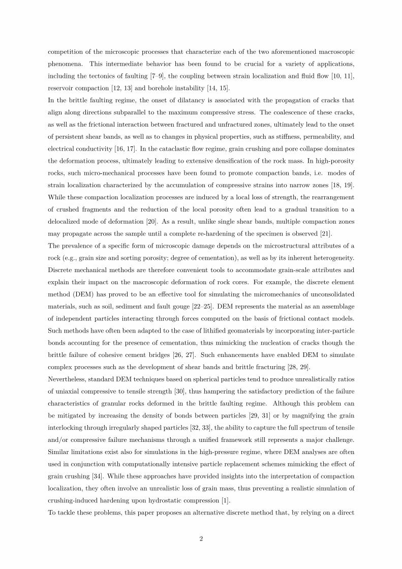
Figure 2: (a) Normal stress versus normal strain in compression. (b) Shear strength as a function of normal compressive
stresses. (c) Shear strength as a function of normal tensile stresses.
boundary ‡bt starts when the maximum e�ective strain reaches its elastic limit e0 (Ê) = ‡0 (Ê) /EN , and
the decay rate is governed by the post-peak slope (softening modulus) H0 (Ê):
H0 (Ê) = Ht
32Ê
fi
4nt
(14)
nt is the softening power and Ht is the softening modulus in pure tension (Ê = fi/2) expressed as
Ht = 2EN /(¸t/¸ ≠ 1) where ¸t = 2EN Gt/‡2t , Gt is the meso-scale fracture energy, and ¸ is the length of
the tetrahedron edge (or interparticle distance) associated with the facet of interest.
4. Calibration and validation
In this section, the constitutive parameters of the LDPM are calibrated and validated for Bleurswiller
sandstone. The experimental data used for calibration and validation purposes are derived from previous
studies on cylindrical specimens of this rock (one for each test) with the diameter of 40 mm and the
height of 80 mm, reported in Fortin et al. [41] and Fortin et al. [42]. All the simulations are done on
a cylindrical specimen with the diameter and height of 2.4 mm as the representative volume with 3,400
simulated grains. The simulation of the actual sample size would lead to over 18,000,000 grains and to
excessive computational cost. Reported data about the grain size distribution of this sandstone indicate
Dmax = 300 µm and Dmin = 160 µm and the mean diameter of 220 µm [41]. As a result, the algorithm
for the generation of the LDPM granular lattice discussed in Section 2 was used to approximate these
limits. The outcome of the trial-and-error calibration procedure with d0=90 µm, da=230 µm, nF =0.5,
‹a=0.58 generates a grain size distribution with a minimum diameter of 145 µm, a maximum diameter
of 305 µm, and a mean diameter of 220 µm (Figure 1f).
8

4.1. Hydrostatic test
The first step of the calibration process involves the parameters governing compression on the LDPM
facets. A hydrostatic test is therefore considered, with the goal to restrain the analysis to a stress path
mobilizing prevalently volumetric compressive loading along the normal LDPM facets. The response
measured from a hydrostatic test on Bleurswiller sandstone is used to calibrate the parameters that
control the elastic and compressive response; the normal modulus (EN =27,155 MPa), the fissure closure
parameter (—1=0.34), the average size of fissure crack opening (w0=0.2 µm), the yielding compressive
stress (‡c0=148 MPa), the rehardening coe�cient (—2=3.5), the initial hardening modulus (Hc0=2,037
MPa) and ec1=4.5ec0. In addition, the shear-normal coupling parameter (–=0.167) is identified by the
value of Poisson’s ratio (‹=0.2) calculated from shear modulus (G=4,000 MPa) and bulk modulus (K=
5,000 MPa) [41]. The simulated response for the hydrostatic test on Bleurswiller sandstone is reported
in Figure 3a together with the relevant experimental data. An excellent agreement between data and
computations is readily apparent both for the initial stage of defect closure and the post-yielding response.
a b
c d
Displacement [m] #10-50 2 4 6 8
Stre
ss [M
Pa]
0
0.5
1
1.5
2
2.5
3
3.5
Gf = 33J/m2
Axial Strain0 0.01 0.02 0.03
q[M
Pa]
0
20
40
60
LDPM(10)Exp.(10)LDPM(100)Exp.(100)
Porosity Reduction (Volumetric Strain)0 0.05 0.1
p[M
Pa]
0
50
100
150
200
250
Exp.LDPM
Volumetric Strain0 0.02 0.04
p[M
Pa]
0
50
100
LDPM(10)Exp.(10)LDPM(100)Exp.(100)
Figure 3: (a) Experimental data (after [41]) and LDPM simulation of hydrostatic test. (b) Load-displacement response of
the direct tension test. (c) Mean stress vs volumetric strain for triaxial tests with 10 and 100 MPa confinement pressures.
(d) Deviatoric stress vs axial strain for triaxial tests with 10 and 100 MPa confinement pressures.
9

4.2. Fracture test
The second step of the parameter calibration involves the parameters that control the response to
tensile loading of the facets, thus leading to meso-scale fracture. In order to calibrate the meso-scale tensile
strength, ‡t and the tensile characteristic length, ¸t, a direct tension test was simulated. In absence of
specific information relevant to Bleurswiller sandstone, the area beneath the stress-displacement curve
and the peak stress (Figure 3b) were compared with typical fracture energy and macroscopic tensile
strength for sandstones found in the literature, 15 to 54 J/m2 [46] and 0.3 to 8 MPa [47], respectively. By
setting ‡t = 2.5 MPa, ¸t=100 mm and nt=0.1, provides Gt=30 J/m2 and one can obtain a macroscopic
fracture energy of Gf =33 J/m2 and a macroscopic tensile strength of 3 MPa. It should be noted that
macroscopic values of fracture energy is greater than the meso-scale value due to the presence of shear
stresses in addition to the normal stresses on the facets which leads to the combination of tensile and
frictional behaviors (mixed fracture mode) even under macroscopic mode 1 fracture conditions. The
macroscopic tensile strength is also greater than the meso-scale tensile strength because the macroscopic
peak stress is attained after stable crack propagation and local re-distribution at the meso-scale.
4.3. Triaxial tests with low and high confining pressures
To calibrate the model parameters controlling the shear behavior (‡s=3.75 MPa, ‡N0=70 MPa,
µ0=0.1 and µŒ=0.05), two triaxial tests at di�erent confining pressures were used, namely 10 MPa (to
account for the brittle response typical of low confinement) and 100 MPa (to account for the response
at high confinement). Figure 3c illustrates the response in terms of mean pressure, p, versus volumetric
strain, while Figure 3d shows the di�erential stress, q, as a function of the axial strain. It is possible
to notice a good general agreement between data and LDPM computations, with the model being able
to capture the brittle-ductile transition from low to high confinements, as well as the change from a
dilative to a contractive volumetric response. While for high confinement the agreement is excellent
from a quantitative standpoint, considerable di�erences can be noted between the amount of softening
predicted by the model and that observed in the experiment at low confining pressure, with the model
significantly underestimating the brittleness of the post-peak response. Such mismatch, however, can
be explained as an outcome of the di�erences between the actual sample tested in the laboratory (the
diameter of the rock cylinders was 40 mm and their length 80 mm) and that simulated by the LDPM
(cylindrical specimens with the diameter and height of 2.4 mm). The role of this size-e�ect induced by
damage localization and strain-softening, will be inspected numerically in the subsequent section.
4.4. Response prediction for triaxial tests and size e�ect analysis
In this section, the calibrated LDPM is used to predict the response of compression tests performed
at di�erent confinement pressures (40, 60 and 80 MPa). The corresponding predictions are plotted in
Figures 4a and 4b which demonstrate a good agreement between LDPM computations and experimental
data, with LDPM capturing the pressure dependence of strength and compressibility, as well as the mean
stress at the onset of shear-enhanced plastic compaction.
Additional triaxial tests were simulated to further explore the role of the size of the numerical sample in
10

the brittle regime of deformation. This e�ect is illustrated in Figures 5a and 5b for 10 MPa confinement
pressure for a cylindrical specimen with 9.6 mm height and 4.8 mm diameter with about 39,600 grains.
It can be noticed that as the specimen size increases, the peak deviatoric stress predicted by the LDPM
decreases and the amount of softening increases. This leads to an improvement of the model peformance
in terms of post-peak behavior and dilative response, which tends to approach more closely the data. This
result corroborates the constitutive choices made for the simulation of tensile fracturing at the meso-scale,
indicating that the proposed model is capable of capturing the typical size dependence of the strength
of quasi-brittle solids. As a result, although di�erences between data and simulations remain also in the
case of a magnified numerical sample, it is arguable that such mismatch can be further mitigated by
approaching the real size of the tested rock core.
In addition, the response for unconfined compression test demonstrates more softening and lower peak
stresses in Figures 5a and 5b and consequently more brittleness of the mechanical behavior. It should
be noted that the inelastic heterogeneity of the LDPM is the factor that automatically triggers and
captures all di�erent failure patterns using one set of meso-scale calibrated parameters and this feature
gives superiority to the model compared to other existing discrete models.
For the unconfined compression test, the computed peak stress was 25 MPa corresponding to about 8
times the macroscopic tensile strength (ft=3 MPa). This ratio is similar to typical values obtained for
other quasi-brittle materials such as ceramics [48] and concrete [49], and therefore corroborates further
the choices made for the selection of the constitutive parameters.
5. Comparison of LDPM results with macroscopic plasticity theories
The previous sections have illustrated the ability of LDPM to simulate the pressure-dependent be-
havior of sandstones across the brittle and ductile regimes of deformation. To benefit of this capability,
here LDPM is used as a virtual simulator to inspect classic concepts of rock plasticity, such as pressure-
dependent yielding and plastic flow, as well as their impact on the strain localization characteristics.
Let us consider for this purpose the deformation response simulated for triaxial compression paths at
varying levels of confinement. Each of the simulated stress-strain curves can be inspected to identify the
points of deviation between linear and non-linear response. Such procedure identifies pressure-dependent
yielding points, which can be plotted in the triaxial stress space, as customarily done for the interpreta-
tion of experiments (Figure 6). Considerable quantitative agreement can be noticed between data and
LDPM predictions, with LDPM being capable of capturing the existence of a plastic cap at high-pressures
as an emergent feature of the hypothesized meso-scale constitutive relations. This feature is consistent
with continuum modeling techniques for porous rocks, as it is emphasized by the comparison between
the LDPM-predicted yielding points and the shape of the yield surface proposed by Lagioia et al. [50],
which was recently used by Buscarnera and coworkers to simulate the plastic yielding of porous rocks of
di�erent mineralogy [20, 51].
Another relevant comparison between the predictions of LDPM and the classical macroscopic descrip-
tion of rock inelasticity involves the predicted directions of plastic flow. A convenient strategy to explore
the stress-dependence of this property involves the evaluation of the dilatancy function d = epv/ep
d, i.e.
11

a
b
Volumetric Strain0 0.01 0.02 0.03 0.04
p[M
Pa]
0
20
40
60
80
100
LDPM(40)Exp.(40)LDPM(60)Exp.(60)LDPM(80)Exp.(80)
Axial Strain0 0.01 0.02 0.03 0.04
q[M
Pa]
0
20
40
60
80
100
LDPM(40)Exp.(40)LDPM(60)Exp.(60)LDPM(80)Exp.(80)
Figure 4: (a) LDPM prediction of p vs volumetric strain. (b) LDPM prediction of q vs axial strain.
the ratio between the increments of volumetric and deviatoric plastic strains. This function is plotted
in Figure 7 versus the stress ratio at yielding, ÷ = q/p. Such plots are provided with reference to both
experimental data (open symbols) and LDPM results (closed symbols). Despite the considerable scatter
of the experimental data, an acceptable agreement can be observed, with LDPM simulations capable
of capturing the decrease in volumetric flow components upon increasing values of stress ratio. Such
trends can also be compared with the analytical expression between the dilatancy ratio and the stress
ratio proposed by Lagioia et al. [50] (often referred to as stress-dilatancy relationship). Such functional
relationship underpins a plastic potential compatible with the yield surface previously discussed with ref-
erence to Figure 6. In addition, it was recently used to study strain localization processes in porous rocks
[51, 52], and it can be readily used for the assessment of the degree of non-normality. The stress-dilatancy
relationship proposed by Lagioia et al. [50] is characterized by the following expression:
d = epv
epd
= ˆg/ˆp
ˆg/ˆq= µg (Mg ≠ ÷)
3–gMg
÷+ 1
4(15)
12

a
b
Volumetric Strain-0.02 -0.01 0 0.01 0.02
p[M
Pa]
0
10
20
30
40
9.6-4.82.4-2.4Exp.(10)UC(2.4-2.4)
Axial Strain0 0.005 0.01 0.015
q[M
Pa]
0
10
20
30
40
50
60
70
9.6-4.82.4-2.4Exp.(10)UC(2.4-2.4)
Figure 5: Size e�ect study for low confinement triaxial test with 10 MPa confinement pressure and unconfined compression
(UC) test.
where Mg represents the stress ratio at which plastic shearing takes place at constant volume (the
so-called critical state), while –g and µg are two shape parameters of the plastic flow rule. When
Equation (15) is used in combination with the parameters that define the shape of the yield locus in
Figure 6 (µg = 1.01, –g = 0.11, Mg = 1.06; dashed line in Figure 7), the stress-dilatancy relationship
provides a graphical representation of the plastic flow directions that would be predicted by a plasticity
model based on an associated flow rule (i.e., it reflects the values of dilatancy ratio that would be
produced by plastic flow directions oriented orthogonally to the yield surface reported in Figure 6). By
contrast, if the same relation is adjusted to encompass the values of dilatancy ratio emerging from the
data and/or the LDPM computations (solid line in Figure 7), a di�erent set of parameters is obtained
(µg = 0.4, –g = 0.45, Mg = 1.6). This result emphasizes the ability of LDPM to capture the macroscopic
notion of non-associated plastic flow, which is here shown to guarantee a better fit of experimental data.
In addition, this finding is compatible with classic bifurcation theories for plastic solids, according to
13

p [MPa]0 50 100 150
q[M
Pa]
0
20
40
60
80ExperimentLDPMYield surface by [50]
A
B C
D
Figure 6: Yield stresses of Bleurswiller sandstone measured through laboratory experiments (closed symbols), computed
through LDPM (open symbols) and fitted through the yield surface expression proposed by Lagioia et al. [50].
which non-associativity is a key component to predict accurately the strain localization potential of
cohesive-frictional materials [53, 54].
To further validate the implications of the predicted non-normality of Bleurswiller sandstone, it is
2
0.5 1 1.5
Dila
tanc
y fu
nctio
n (d
)
-1
0
1
2
3
4(40)(60)(80)(100)LDPM(40)LDPM(60)LDPM(80)LDPM(100)AssociatedNon-associated
Figure 7: Dilatancy function as a function of ÷ = q/p.
convenient to test the ability of LDPM to simulate the onset of pressure-dependent strain-localization.
For this purpose, the predicted fracture patterns in terms of meso-scale total crack openings wtotal defined
by Equation (16) for facets with tensile normal strain, and compression bands in terms of compactive
strains ecomp defined by Equation (17) for facets with compressive normal strain can be used to map the
spatial distribution of concentrated inelastic processes, and hence to identify the active zones of strain
localization. One can write:
wtotal = ¸Ò
e2N + e2
L + e2M (for eN < 0) (16)
14

and
ecomp =Ò
e2N + e2
L + e2M (for eN > 0) (17)
To study the e�ect of the mean pressure, four tests were chosen and their associated locations on the
yield cap were marked in Figure 6: an unconfined compression test (A), and three triaxial tests at 10
MPa (B), 40 MPa (C) and 80 MPa (D) confinement. The total crack opening is selected as the metric
for the interpretation of the simulations at the two lowest levels of confinement (brittle regime), while
the total compactive strain is used for the interpretation of the two triaxial tests at the highest levels of
confinement pressure.
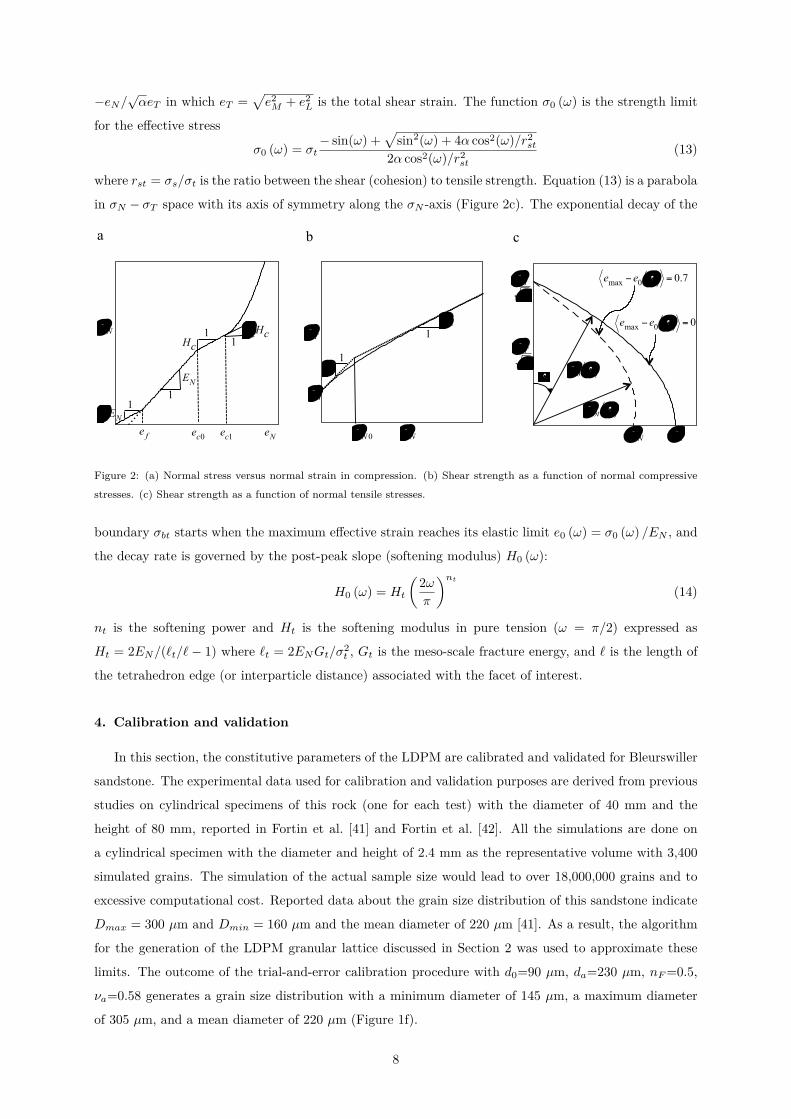
Figure 8a depicts the fracture patterns computed for the unconfined compression test at ev =-0.02
and p =7 MPa, illustrating the formation of concentrated, inclined sub-vertical cracks typical of the
brittle fracturing observed during unconfined compression. Figure 8b illustrates the results obtained for
a triaxial test simulated at low confinement pressure of 10 MPa at ev =-0.02 and p =31 MPa, thus
displaying localized discrete fracture planes oriented along shear bands similar to those reported by
Fortin et al. [42] (shear-enhanced dilation and brittle faulting). For triaxial test simulated at 40 MPa
confinement, Fortin et al. [41] report a combination of localization bands oriented perpendicular to the
maximum principal stress (compaction bands), and slightly inclined localization bands characterized by
mixed shear/compaction deformation. Also in this case, both types of localized inelastic processes can be
found in the numerical simulation illustrated in Figure 8c for ev =0.03 and p =67 MPa. Finally, at the
high confining pressure of 80 MPa at ev =0.043 and p =103 MPa, the inelastic deformations predicted by
LDPM are localized into several compaction bands nearly orthogonal to the maximum compressive stress,
corresponding well to the deformation patterns reported by Fortin et al. [41] at the same confinement
pressure (Figure 8d).
6. Conclusion
Granular rocks exhibit pressure-dependent properties, as well as a broad range of strain-localization
modes. Such materials are in fact characterized by various types of micro-scale heterogeneity, which
generate macroscopic patterns that can be traced back to processes such as crack initiation; crack propa-
gation; and interaction between fractured and unfractured material. Advanced multi-scale computations
are thus required to simulate such patterns and correlate them with basic micro-scale processes. This
paper has shown that LDPM is a framework able to fulfill such objectives for the important case of
granular rocks. This feature has been discussed by presenting a strategy to incorporate into model com-
putations grain-scale rock heterogeneity, i.e. the scale at which microscopic inelastic processes take place.
A particular granular rock has been selected for model illustration purposes, the Bleurswiller sandstone,
thus benefiting from the large availability of data about its mechanical response. The presented results
show that by incorporating specific features, such as the crack closure upon compression and the develop-
ment of pore collapse upon high-pressure compression, it is possible to capture a variety of macroscopic
processes, such as the inelastic hydrostatic compression of rock samples, the brittle fracture upon ten-
sion, and the transition from brittle/dilative response to ductile/compactive behavior. Most notably, the
15
Total crack opening
0.0002
0.0004
0.0001
0.00055
A
0.015%
0.010%
0.005%
0.0025%
[mm]% Total crack opening
0.0007
0.0014
0.0001
0.0020.050%
0.035%
0.020%
0.0025%
[mm]%
B
Total compactive strain
0.03
0.05
0.003
0.07
D
[+]% 0.07%
0.05%
0.03%
0.003%
a b
c d
Total compactive strain
0.1
0.3
0.03
0.4
C
[+]% 0.4%
0.3%
0.1%
0.03%
Figure 8: (a),(b) LDPM fracture patterns for unconfined compression test and triaxial test with 10 MPa confinement
pressure. (c),(d) LDPM compactive strain contours for triaxial tests with 40 MPa and 80 MPa confinement pressures.
ability to predict such wide range of responses is based only on a limited set of data used for paramet-
ric identification, thus indicating that LDPM represents a versatile tool for a variety of geomechanical
modeling applications, ranging from the intetpretation of multi-scale experiments, to the prediction of
strain heterogeneities, to the formulation of continuum models and the assessment of their predictive
capabilities.
7. Acknowledgment
The authors would like to acknowledge the Institute for Sustainability and Energy at Northwestern
(ISEN) funding scheme.
8. References
[1] T.-f. Wong, P. Baud, The brittle-ductile transition in porous rock: A review, Journal of Structural
Geology 44 (2012) 25–53.
[2] B. Menéndez, W. Zhu, T.-F. Wong, Micromechanics of brittle faulting and cataclastic flow in berea
sandstone, Journal of Structural Geology 18 (1996) 1–16.
16

[3] T.-F. Wong, C. David, W. Zhu, The transition from brittle faulting to cataclastic flow in porous
sandstones: Mechanical deformation, Journal of Geophysical Research: Solid Earth 102 (1997)
3009–3025.
[4] P. Baud, E. Klein, T.-f. Wong, Compaction localization in porous sandstones: spatial evolution of
damage and acoustic emission activity, Journal of Structural Geology 26 (2004) 603–624.
[5] T.-f. Wong, P. Baud, E. Klein, Localized failure modes in a compactant porous rock, Geophysical
Research Letters 28 (2001) 2521–2524.
[6] H. Fossen, R. A. Schultz, Z. K. Shipton, K. Mair, Deformation bands in sandstone: a review, Journal
of the Geological Society, London 164 (2007) 1–15.
[7] A. Aydin, A. M. Johnson, Development of faults as zones of deformation bands and as slip surfaces
in sandstone, Pure Appl. Geophys 116 (1978) 931–942.
[8] W. R. Jamison, D. W. Stearns, Tectonic deformation of wingate sandstone, colorado national
monument, Am. Assoc. Pet. Geol. Bull. 66 (1982) 2584–2608.
[9] Z. K. Shipton, P. A. Cowie, Damage zone and slip-surface evolution over µm to km scales in
high-porosity navajo sandstone, Utah. J. Struct. Geol. 23 (2001) 1825–1844.
[10] R. J. Knipe, Juxtaposition and seal diagrams to help analyze fault seals in hydrocarbon reservoirs,
AAPG Bull. 81 (1997) 187–195.
[11] T.-F. Wong, W. Zhu, Brittle faulting and permeability evolution: hydrome- chanical measurement,
microstructural observation, and network modeling. in: Haneberg, W.C., Mozley, P.S., Moore, C.,
Goodwin, L.B. (Eds.), faults and subsurface fluid flow in the shallow crust, Geophysical Monograph
113 (1999) 83–99.
[12] M. Boutéca, J.-P. Sarda, F. Schneider, Subsidence induced by the production of fluids, Rev. Inst.
Franc. Petr. 51 (1996) 349–379.
[13] N. Nagel, Compaction and subsidence issues within the petroleum industry: From wilmington to
ekofisk and beyond, Physics and Chemistry of the Earth, Part A: Solid Earth and Geodesy 26 (2001)
3–14.
[14] C. A. M. Veeken, J. V. Walters, C. J. Kenter, D. R. Davis, Use of plasticity models for predicting
borehole stability. in: Maury, V., Fourmaintraux, D. (Eds.), Rocks at Great Depth 2 (1989) 835–844.
[15] L. Coelho, A. C. Soares, N. F. F. Ebecken, J. L. D. Alves, L. Landau, The impact of constitutive
modeling of porous rocks on 2-D wellbore stability analysis, J. Petrol. Sci. Eng. 46 (2005) 81–100.
[16] G. Dresen, Y. Guéguen, Damage and rock physical properties, Elsevier, Amsterdam, 2004.
[17] M. S. Paterson, T.-F. Wong, Experimental Rock Deformation - The Brittle Field, Spinger-Verlag,
New York, 2005.
17
[18] P. N. Mollema, M. A. Antonellini, Compaction bands: A structural analog for anti-mode i cracks in
aeolian sandstone, Techtonophysics 267 (1996) 209–228.
[19] W. A. Olsson, Theoretical and experimental investigation of compaction bands in porous rock,
Journal of Geophysical Research: Solid Earth 104 (1999) 7219–7228.
[20] A. Das, G. Buscarnera, Simulation of localized compaction in high-porosity calcarenite subjected
to boundary constraints, International Journal of Rock Mechanics and Mining Sciences 71 (2014)
91–104.
[21] D. J. Holcomb, W. A. Olsson, Compaction localization and fluid flow, Journal of Geophysical
Research: Solid Earth 108 (2003).
[22] P. A. Cundall, O. D. L. Strack, A discrete numerical model for granular assemblies, Geotechnique
29 (1979) 47–65.
[23] M. A. Antonellini, D. D. Pollard, Distinct element modeling of deformation bands in sandstone, J.
Struct. Geol. 17 (1995) 1165–1182.
[24] J. K. Morgan, M. S. Boettcher, Numerical simulations of granular shear zones using the distinct
element method, 1. Shear zone kinematics and the micromechanics of localization, J. Geophys. Res.
104 (1999) 2703–2719.
[25] E. Aharonov, D. W. Sparks, Shear profiles and localization in simulations of granular materials,
Phys. Rev. E 65 (2002) 1–12.
[26] D. O. Potyondy, P. A. Cundall, C. Lee, Modeling rock using bonded assemblies of circular particles,
Proc. North Am. Rock Mech. Symp. 2 (1996) 1937–1944.
[27] D. O. Potyondy, P. A. Cundall, A bonded particle model for rock, Int J Rock Mech Min Sci. 41
(2004) 1329–1364.
[28] M. Schöpfer, C. Childs, The impact of porosity and crack density on the elasticity, strength and
friction of cohesive granular materials: insights from dem modeling, Int J Rock Mech Min Sci. 57
(2013) 75–88.
[29] L. Scholtès, F.-V. Donzé, A dem model for soft and hard rocks: Role of grain interlocking on
strength, J. Mech. Phys. Solids 61 (2013) 352–369.
[30] B. Altindag, A. Guney, Predicting the relationships between brittleness and mechanical properties
(UCS, TS and SH) of rocks, Sci. Res. Essays 5 (2010) 2107–2118.
[31] F.-V. Donzé, J. Bouchez, S. A. Magnier, Modeling fractures in rock blasting, Int. J. Rock Mech.
Mining Sci. 34 (1997) 1153–1163.
[32] N. Cho, C. D. Martin, D. C. Sego, A clumped particle model for rock, Int. J. Rock Mech. Mining
Sci. 44 (2007) 997–1010.
18

[33] H. Lan, C. D. Martin, B. Hu, E�ect of heterogeneity of brittle rock on micromechanical extensile
behavior during compression loading, J. Geophys. Res. 115 (2010) doi:10.1029/2009JB006496.
[34] G. R. McDowell, J. P. D. Bono, On the micro mechanics of one-dimensional normal compression,
Geotechnique 63 (2013) 895–908.
[35] G. Cusatis, A. Mencarelli, D. Pelessone, J. Baylot, Lattice discrete particle model (LDPM) for
failure behavior of concrete. I: Theory, Cement and Concrete Composites 33 (2011) 881–890.
[36] G. Cusatis, A. Mencarelli, D. Pelessone, J. Baylot, Lattice discrete particle model (LDPM) for
failure behavior of concrete. II: Calibration and validation, Cement and Concrete Composites 33
(2011) 891–905.
[37] M. Alnaggar, G. Cusatis, G. D. Luzio, Lattice discrete particle modeling of alkali-silica-reaction
(ASR) deterioration of concrete structures, Cement and Concrete Composites Journal 41 (2013)
45–59.
[38] J. Smith, G. Cusatis, D. Pelessone, E. Landis, J. O’Daniels, J. Baylot, Lattice discrete particle
modeling of ultra high-performance fiber-reinforced concrete for projectile penetration simulations,
International Journal of Impact Engineering 65 (2014) 13–32.
[39] S. Esna Ashari, G. Buscarnera, G. Cusatis, Micro-scale modeling of the inelastic response of a
granular sandstone, in: Proceedings of the 49th US Rock Mechanics/Geomechanics Symposium,
San Francisco, CA, USA, 2015.
[40] R. Rezakhani, G. Cusatis, Asymptotic expansion homogenization of discrete fine-scale models with
rotational degrees of freedom for the simulation of quasi-brittle materials, J. Mech. Phys. Solids
(2016) In press.
[41] J. Fortin, A. Schubnel, Y. Guéguen, Elastic wave velocities and permeability evolution during
compaction of bleurswiller sandstone, International Journal of Rock Mechanics and Mining Sciences
42 (2005) 873 – 889. Rock Physics and Geomechanics Rock Physics and Geomechanics.
[42] J. Fortin, S. Stanchits, G. Dresen, Y. Gueguen, Acoustic emissions monitoring during inelastic
deformation of porous sandstone: Comparison of three modes of deformation, in: S. Vinciguerra,
Y. Bernabé (Eds.), Rock Physics and Natural Hazards, Pageoph Topical Volumes, Birkhäuser Basel,
2009, pp. 823–841.
[43] F. C. Caner, Z. P. Baûant, Microplane model M7 for plain concrete. i: formulation, J Eng Mech 139
(2013) 1714–1723.
[44] Z. P. Baûant, F. C. Caner, I. Carol, M. D. Adley, S. A. Akers, Microplane model M4 for concrete.
i: formulation with work-conjugate deviatoric stress, J Eng Mech 126 (2000) 944–953.
[45] C. Ceccato, C. Pellegrino, G. Cusatis, Lattice discrete particle modeling (ldpm) of fiber reinforced
polymers (frp) confined concrete columns, in: Proceedings of the 12th international symposium on
fiber reinforced concrete structures, Nanjing, China, 2015.
19

[46] B. K. Atkinson, Fracture mechanics of rock, Academic Press, 1987.
[47] R. G. Hoagland, G. T. Hahn, A. R. Rosenfield, Influence of microstructure on fracture propagation
in rock, Rock Mechanics 5 (1973) 77–106.
[48] D. E. Grady, Dynamic failure in brittle solids, in: Proceedings of Europe-US Workshop on Fracture
and Damage in Quasibrittle Structures: Experiment, Modeling and Computer Analysis, Prague,
Czechoslovakia, 1994.
[49] R. H. J. Peerlings, R. de Borst, W. A. M. Brekelmans, M. G. D. Geers, Gradient-enhanced damage
modelling of concrete fracture, Mech. Cohes.-Frict. Mater. 3 (1998) 323–342.
[50] R. Lagioia, A. M. Puzrin, D. M. Potts, A new versatile expression for yield and plastic potential
surfaces, Computers and Geotechnics 19 (1996) 171–191.
[51] F. Marinelli, G. Buscarnera, Parameter calibration for high-porosity sandstones deformed in the
compaction banding regime, Int. J. Rock Mech. Mining Sci. 78 (2015) 240–252.
[52] G. Buscarnera, R. T. Laverack, Path dependence of the potential for compaction banding: Theo-
retical predictions based on a plasticity model for porous rocks, Journal of Geophysical Research:
Solid Earth 119 (2014) 1882–1903.
[53] J. Rudnicki, J. Rice, Conditions for the localization of deformation in pressure-sensitive dilatant
materials, Journal of the Mechanics and Physics of Solids 23 (1975) 371–394.
[54] K. A. Issen, J. W. Rudnicki, Conditions for compaction bands in porous rock, Journal of Geophysical
Research: Solid Earth 105 (2000) 21529–21536.
20


