
1
Lect- 4

Prof. Bhaskar Roy, Prof. A M Pradeep, Department of Aerospace, IIT Bombay 2
Lect-4
In this lecture...
• Performance parameters: cascade analysis
• 2-D losses in axial compressor stage –primary losses

Prof. Bhaskar Roy, Prof. A M Pradeep, Department of Aerospace, IIT Bombay 3
Lect-4
Performance parameters• Measurements from cascade: velocities,
pressures, flow angles ...• Loss in total pressure expressed as total
pressure loss coefficient
• Total pressure loss is very sensitive to changes in the incidence angle.
• At very high incidences, flow is likely to separate from the blade surfaces, eventually leading to stalling of the blade.
212
10201
VPP
PLC ρω −
=
Prof. Bhaskar Roy, Prof. A M Pradeep, Department of Aerospace, IIT Bombay 4
Lect-4
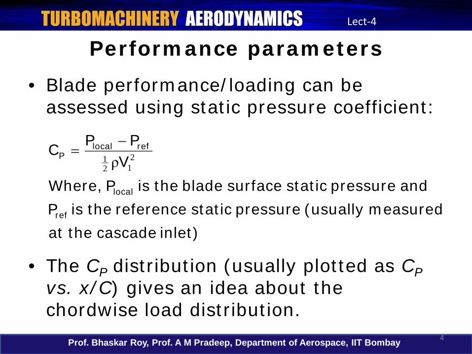
Performance parameters• Blade performance/loading can be
assessed using static pressure coefficient:
• The CP distribution (usually plotted as CPvs. x/C) gives an idea about the chordwise load distribution.
inlet) cascade the at measured (usually pressure static reference the isP
and pressure static surface blade the is P Where,V
PPC
ref
local
reflocalP 2
121 ρ−
=

Prof. Bhaskar Roy, Prof. A M Pradeep, Department of Aerospace, IIT Bombay 5
Lect-4
Performance parameters
Def
lect
ion,
deg
rees
Tota
l pre
ssur
e lo
ss c
oeffi
cien
t
Position along cascade
Location of the blade trailing edge

Prof. Bhaskar Roy, Prof. A M Pradeep, Department of Aerospace, IIT Bombay 6
Lect-4
Performance parameters
β1
β2 β2
β1
C1
C2C2
C1 Stalled or separated flow
(a) Normal operation (b) Stalled operation

Prof. Bhaskar Roy, Prof. A M Pradeep, Department of Aerospace, IIT Bombay 7
Lect-4
Performance parameters
Incidence angle, degrees
Tota
l pre
ssur
e lo
ss c
oeffi
cien
t
Prof. Bhaskar Roy, Prof. A M Pradeep, Department of Aerospace, IIT Bombay 8
Lect-4
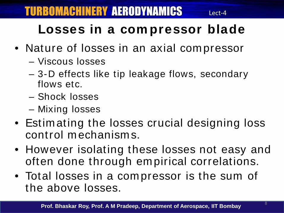
Losses in a compressor blade• Nature of losses in an axial compressor
– Viscous losses – 3-D effects like tip leakage flows, secondary
flows etc.– Shock losses– Mixing losses
• Estimating the losses crucial designing loss control mechanisms.
• However isolating these losses not easy and often done through empirical correlations.
• Total losses in a compressor is the sum of the above losses.
Prof. Bhaskar Roy, Prof. A M Pradeep, Department of Aerospace, IIT Bombay 9
Lect-4
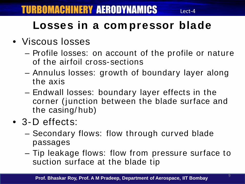
Losses in a compressor blade• Viscous losses
– Profile losses: on account of the profile or nature of the airfoil cross-sections
– Annulus losses: growth of boundary layer along the axis
– Endwall losses: boundary layer effects in the corner (junction between the blade surface and the casing/hub)
• 3-D effects:– Secondary flows: flow through curved blade
passages– Tip leakage flows: flow from pressure surface to
suction surface at the blade tip
Prof. Bhaskar Roy, Prof. A M Pradeep, Department of Aerospace, IIT Bombay 10
Lect-4
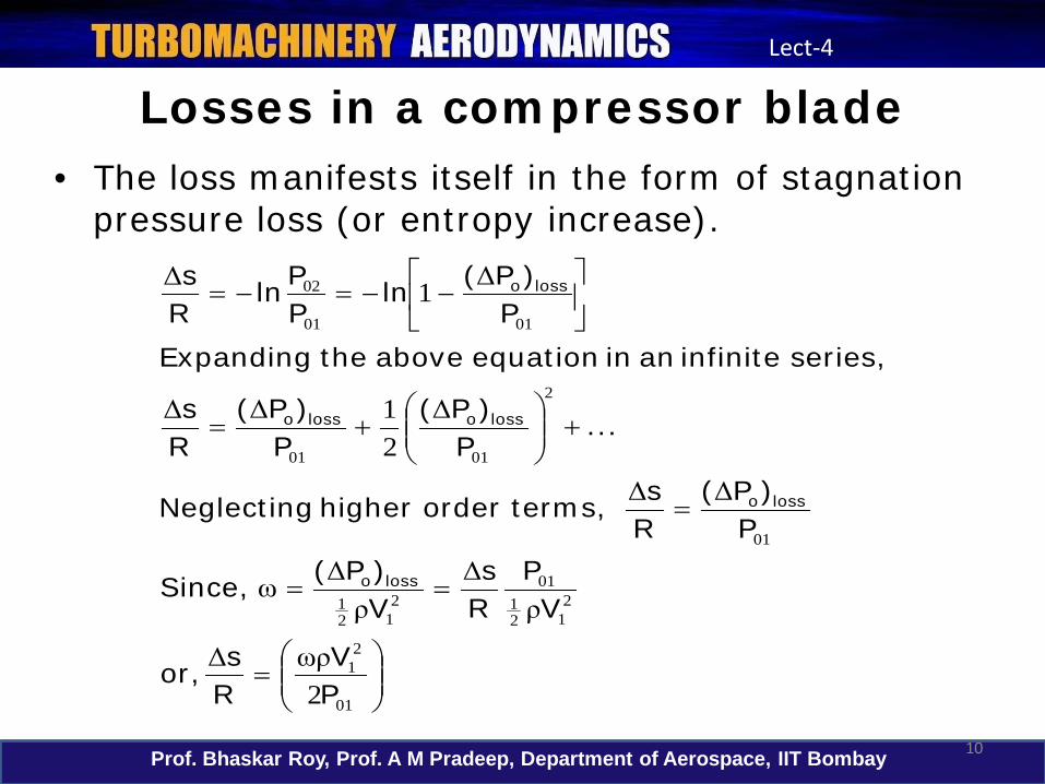
Losses in a compressor blade• The loss manifests itself in the form of stagnation
pressure loss (or entropy increase).
=
==
=
+
+=
−−=−=
01
21
212
101
212
1
01
2
0101
0101
02
2
21
1
PV
Rs,or
VP
Rs
V)P( Since,
P)P(
Rsterms,order higher Neglecting
...P
)P(P
)P(Rs
series, infinite an in equation above the ExpandingP
)P(lnPPln
Rs
losso
losso
lossolosso
losso
ωρΔ
ρΔ
ρΔω
ΔΔ
ΔΔΔ
ΔΔ
Prof. Bhaskar Roy, Prof. A M Pradeep, Department of Aerospace, IIT Bombay 11
Lect-4
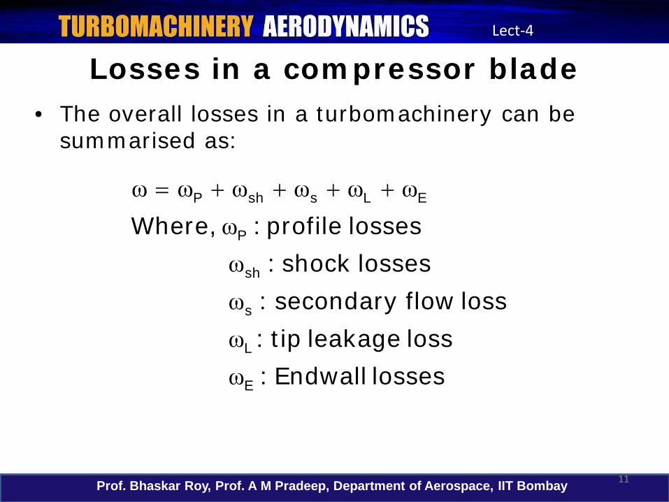
Losses in a compressor blade• The overall losses in a turbomachinery can be
summarised as:
losses Endwall:loss leakage tip :
loss flow secondary:lossesshock :
losses profile :Where,
E
L
s
sh
P
ELsshP
ωωωωω
ωωωωωω ++++=
Prof. Bhaskar Roy, Prof. A M Pradeep, Department of Aerospace, IIT Bombay 12
Lect-4
2-D Losses in a compressor blade• 2-D losses are relevant only to axial flow
turbomachines.• These are mainly associated with blade
boundary layers, shock-boundary layer interactions, separated flows and wakes.
• The mixing of the wake downstream produces additional losses called mixing losses.
• The maximum losses occur near the blade surface and minimum loss occurs near the edge of the boundary layer.

Prof. Bhaskar Roy, Prof. A M Pradeep, Department of Aerospace, IIT Bombay 13
Lect-4
2-D Losses in a compressor blade
• 2-D losses can be classified as:• Profile loss due to boundary layer, including
laminar and/or turbulent separation.• Wake mixing losses• Shock losses• Trailing edge loss due to the blade.

Prof. Bhaskar Roy, Prof. A M Pradeep, Department of Aerospace, IIT Bombay 14
Lect-4
2-D Losses in a compressor blade
• The profile loss depends upon:• Flow parameters like Reynolds number,
Mach number, longitudinal curvature of the blade, inlet turbulence, free-stream unsteadiness and the resulting unsteady boundary layers, pressure gradient, and shock strength
• Blade parameters like: thickness, camber, solidity, sweep, skewness of the blade, stagger angle and blade roughness.
Prof. Bhaskar Roy, Prof. A M Pradeep, Department of Aerospace, IIT Bombay 15
Lect-4
2-D Losses in a compressor blade• The mixing losses arise as a result of the
mixing of the wake with the freestream. • This depends upon, in addition to the
parameters mentioned in the previous slide, the distance downstream.
• The physical mechanism is the exchange of momentum and energy between the wake and the freestream.
• This transfer of energy results in the decay of the free shear layer, increased wake centre line velocity and increased wake width.
Prof. Bhaskar Roy, Prof. A M Pradeep, Department of Aerospace, IIT Bombay 16
Lect-4
2-D Losses in a compressor blade• At far downstream, the flow becomes
uniform.• Theoretically, the difference between the
stagnation pressure far downstream and the trailing edge represents the mixing loss.
• Most loss correlations are based on measurements downstream of the trailing edge (1/2 to 1 chord length) and therefore do not include all the mixing losses.
• If there is flow separation, the losses would include losses due to this zone and at its eventual mixing downstream.
Prof. Bhaskar Roy, Prof. A M Pradeep, Department of Aerospace, IIT Bombay 17
Lect-4
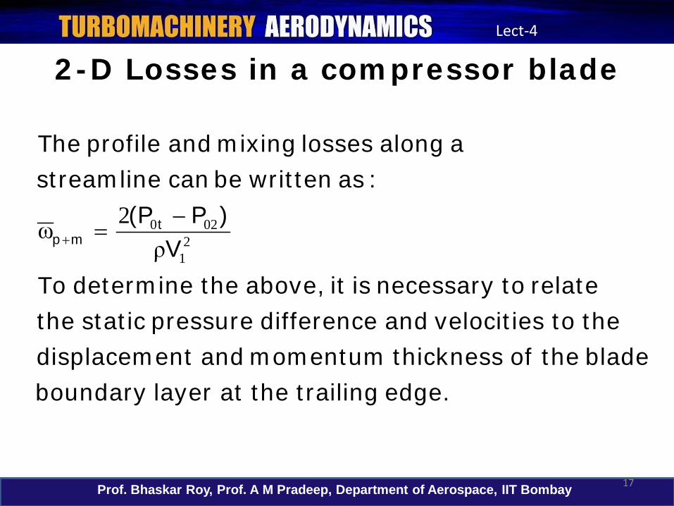
2-D Losses in a compressor blade
edge. trailing the atlayer boundaryblade the of thickness momentum and ntdisplaceme
the to velocities and difference pressure static therelate to necessary is it above, the determine To
V)PP(
:as written be can streamline a along losses mixing and profile The
tmp 2
1
0202ρ
ω −=+

Prof. Bhaskar Roy, Prof. A M Pradeep, Department of Aerospace, IIT Bombay 18
Lect-4
2-D Losses in a compressor blade
.thicknesssmomentumtheisand)thicknessntdisplacemetorelated(blockagetheis,Where
)tan(sec,termsorderhigherNeglecting
)()(tan
)(sec
:as expressedfurther is ThisV
VVV
)pp(V
)PP(6).(Chapter book sayana'Lakshminar in given are nscorrelatio these of derivation Detailed
mp
mp
tttmp
ΘΔ
αΘΘαω
ΔΘΔα
ΔΔΘαω
ρρω
22
12
2
2
22
2
2
12
21
22
2
21
22
1
020
2
11
11
2
22
+=
−−−
−+
−+
=
−+
−=
−=
+
+
+
Prof. Bhaskar Roy, Prof. A M Pradeep, Department of Aerospace, IIT Bombay 19
Lect-4
2-D Losses in a compressor blade
• Thus, in a simplified manner, we see that the profile loss can be estimated based on the momentum thickness.
• The above loss correlation includes both profile and wake mixing loss.
• If flow separation occurs, additional losses are incurred. This is because the pressuredistribution is drastically altered beyond the separation point.
• The losses increase due to increase in boundary layer displacement and momentum thicknesses.

Prof. Bhaskar Roy, Prof. A M Pradeep, Department of Aerospace, IIT Bombay 20
Lect-4
2-D Losses in a compressor blade
• In addition to the losses discussed above, boundary layer growth and subsequent decay of the wake causes deviation in the outlet angle.
• An estimate of this is given as:
• Hence, viscous effect in a turbomachine always leads to decrease in the turning angle.
• The values of displacement and momentum thicknesses, depend upon, variation of freestream velocity, Mach number, skin friction, pressure gradient, turbulence intensity and Reynolds number.
ttan)(tan αΔΘα −−≈ 12

Prof. Bhaskar Roy, Prof. A M Pradeep, Department of Aerospace, IIT Bombay 21
Lect-4
2-D Losses in a compressor blade
• In general, the loss estimation may be carried out using one of the following methods:• Separate calculation of the potential or
inviscid flow and the displacement and momentum thicknesses. Subsequently, use the equation discussed previously.
• Using a Navier-Stokes based computational code. Here the local and the integrated losses can be computed directly.

Prof. Bhaskar Roy, Prof. A M Pradeep, Department of Aerospace, IIT Bombay 22
Lect-4
Mach number and shock losses
• The static pressure rise in a compressor increases with Mach number.
• Thus the pressure gradient increases with increase in Mach number.
• This means that the momentum thickness and hence the losses increase with Mach number.
• Increasing Mach numbers also lead to increase in shock losses.
• At transonic speeds, the shock losses are very sensitive to leading and trailing edge geometries.

Prof. Bhaskar Roy, Prof. A M Pradeep, Department of Aerospace, IIT Bombay 23
Lect-4
Mach number and shock losses• An estimate of the 2-D shock losses for a
compressor must include:• The losses due to the leading edge bluntness
with supersonic upstream Mach number.• The location of the passage shock can be
determined from inviscid theories. If the shock strength is known, the losses can be estimated.
• The losses due to boundary layer growth and the shock-boundary layer interaction are most difficult to estimate. The contribution however is small for weak shocks.

Prof. Bhaskar Roy, Prof. A M Pradeep, Department of Aerospace, IIT Bombay 24
Lect-4
Mach number and shock losses• One of the empirical correlations for the shock
loss was given by Freeman and Cumpsty(1989).
• This is valid for an incidence angle upto 5o.• These empirical correlations are however,
derived using the 2-D assumption. • Actual flows are seldom 2-D in nature.
[ ].angleinletbladetheis,where
)()(..
pP)P(
pP)P(
'
''
shocknormal
losslosssh
1
1120
1
101
0
101
0
106518062
α
ααα
ΔΔω
−−++
−
=−
=
−
Prof. Bhaskar Roy, Prof. A M Pradeep, Department of Aerospace, IIT Bombay 25
Lect-4
In this lecture...
• Performance parameters: cascade analysis
• 2-D losses in axial compressor stage –primary losses
Prof. Bhaskar Roy, Prof. A M Pradeep, Department of Aerospace, IIT Bombay 26
Lect-4
In the next lecture...
• Tutorial: solved examples and tutorial problems.


