
1/16” Through 11/2”-inch
2 mm Through 25 mm-Metric

LET-LOK® HOW DOES IT WORK ?
LET-LOK® tube fittings are composed of four parts:1. body 2. front ferrule 3. back ferrule 4. nut.
Tube Nut Back FerruleBody Front Ferrule
3214
LET-LOK®
DESCRIPTIONThe HAM-LET® GROUP has produced
high quality tube and pipe fittings in
various materials for high pressure
applications since its establishment in
1950.
For almost five decades, through
tremendous efforts in research and
development, HAM-LET® has gained
an excellent reputation as a leading
manufacturer of high pressure
instrumentation products.
The LET-LOK® range of connectors
has been developed to fill the rapidly
increasing demand for tube fittings
suitable for high pressure use in
environments such as petrochemical,
fluid, power, nuclear, electronic, as well
as other major industries.
LET-LOK® tube fittings have been
carefully manufactured and tested to
withstand the demands of high
performance tube fittings, such as high
pressure, impulse, vibration, vacuum
and temperature.
These tube fittings are manufactured
to exacting tolerances using the most
modern and advanced computerized
automation. One of the main conditions
required to producing these precision
machined fittings is the maintenance
of stringent quality control in conjunction
with skilled craftsmen.
The LET-LOK® tube fitting is a
mechanism used for both sealing and
gripping tubing. The mechanical
advantage and geometry of fitting
produces a leak-tight assembly.
To assemble, simply insert the tube
into the complete assembly until the
tube bottoms-out against the shoulder
of the fitting body.
The two ferrules are driven forward
between the nut and fitting body using
the mechanical force created by rotating
the nut clockwise. The back ferrule (3)
is driven against the tapered rear of
the front ferrule (2) and the frontferrule is driven by force into the tapered
mouth of the body.
The rear ferrule is swaged radially
inwards on the tube while lifting the
front ferrule out to form a full faced seal
on the tapered surface of the body.
The 11/4 turn on the nut from the hand
tight position assures consistent drive
of the sealing members. This ensures
an effective seal against high pressure
as well as ultra high vacuum conditions.
DO
UB
LE
FE
RR
UL
E F
ITT
ING
S
1

REASSEMBLYINSTRUCTIONSLET- L O K ® connections may bedisconnected and remade repeatedly,without loss of leaktight seal.
1. Before disconnecting, mark the position of the nut in relationto the fitting body.
2.To reassemble, use a wrenchto tighten nut to originalposition.
3.Tighten slightly with wrenchuntil a slight rise in torque isfelt.
TUBE CUTTINGTwo different methods can be usedto cut tubes:
1. Tube cutter
2. Hacksaw
TUBE CUTTERTo attain a leak free connection, thetubing must be cut squarely.A good quality tube cutter with theappropriate blade for the tubingmaterial is recommended.Do not try to reduce the time of cuttingby taking deep cuts with each turn ofthe cutter. This will work harden thetube.The end of the tube must be deburredto avoid damage to the fitting and toensure that the tube reaches thebottom of the fitting.
HACKSAW CUTTINGIn order to cut the tube with a hacksawand get square ends, the tube mustbe cut with guide blocks.This method of cutting necessitatesdeburring of the tube ends.
TUBE HANDLINGScratches on the tube might causeleaks.It is,Therefore, importantto handle the tube carefully toreduce the risk of leaks.
SOME PRECAUTIONS TO BETAKEN:1. Tubes must not be dragged on
the floor.2.Tubes must not be dragged out
of a tubing rack, especially incase of large OD tubes.
COPPER TUBINGIf using copper tubing from a rol, holdthe end of the tube and roll the rolloutwards allowing the tubing to lie ona flat surface.
INSPECTION GAUGEUse: This is a "No-Go" gauge andshould be used as follows:1. Make up the fitting according to the
following instructions: 1/4 inch (6mm),3/8 inch, 1/2 inch (12mm) - makeup 1.1/4 turns from finger tight.
2. Check gap between nut and body,using the appropriate sized gauge.Ifthe gauge slides easily into the gap,tighten the nut further until gaugecan not enter the gap.
To order, use part No. 3900098Availble only in:1/4 inch (6mm), 3/8 inch,1/2 inch (12mm) - make up 1.1/4
Gauge entersgap...No good,tighten further
Gauge doesnot entergap...Good.
LET-LOK® INSTALLATION INSTRUCTIONS
1
2
LET-LOK® fittings are supplied assembled, finger tight. Disassembly beforeuse can allow the entry of dirt or other particles.
WarningDo not hold the tube in a vise in theplace where it will be inserted into thefitting (the vise will leave a mark on thetube that may cause leaks, and mightcause ovality).
Figure A Figure B
0
3/41/4
1/2
01
3/4 1/4 1/41
1/2
DO
UB
LE
FE
RR
UL
E F
ITT
ING
S
2
Insert the tubing into the LET-LOK®
fitting. Check that the tube rests firmlyon the fitting shoulder and that the nutis finger tight. At this point it isrecommended that a scribe mark bedrawn on the hex of the nut extendingonto the fitting body. This mark willserve as an indicator for the startingpoint and proper pull-up.
Tighten the nut. (see Fig. A & B)1 1/4 turns of the nut are required for1/4" (6 mm) and higher.3/4 turn of the nut is required for 3/16"(4 mm) and lower.

LET-LOK® METRIC FITTINGS:Tee & Elbow (see Fig. 1),Body marked: MMStraight Connectors (see Fig. 2)Body: Stepped shoulder,Marked: LET-LOK 316 AV1(2)
Nut: (see Figs.1 & 2) Stepped shoulderShoulder marked LET-LOK 316 6M(1) SD8(2)
LET-LOK® INCH FITTINGS:Tee & Elbow (See Fig. 3)Straight Fittings, (see Fig. 4)Body: Shoulder marked:LET-LOK 316 AV2(2)
Nut (See Fig. 3 & 4): Shoulder markedLET-LOK 316 1/2(1) BU2(2)
(1) Tube O.D. (2) Material Batch
LET-LOK®
HIGH SAFETYIn applications where severe conditionsand high pressure exist, we recommendthe following installation procedures:1. Check that the nut is finger tight.2. Insert the tube (up to the shoulder).3. Rotate the nut with a wrench until
the tube does not rotate freely.4. Mark position of the nut.5. Rotate the nut 11/4 turns.This method ensures that even if thetube O.D. is at the minimum tolerance,the ferrules will be in contact with thetube for the full 11/4 rotation.
TUBING DATA FORLET-LOK® FITTINGSIn order to assure maximum fittingreliability and performance, great careshould be given when selecting thetubing for each application.
TUBE SELECTION:Four variables must be consideredwhen ordering tube for use with LET-LOK® fittings:1. Material2. Tube wall thickness3. Tube surface finish4. Tube hardness
Tubing should comply with standardASTM A213 or ASTM A269, beseamless, and fully annealed.The tube must be free of scratchesand suitable for bending and flaring.
Ovality of twice OD tolerance is
not suitable for LET-LOK fittings.
The tube must be reasonably
round. The ends of the tube must
be free of burrs.
Tubing hardness: The hardness
of the tube must be lower than the
hardness of the fitting material.
The hardness must be not more
than Rockwell HRB 80.
TUBE OD TOLERANCES:
Fig.3
LET-LOK316 1/2 BU2
Fig.4
LET-LOK 316 AV2
Fig.2
LET-LOK316 AV1
SteppedShoulder
Fig.1
LET-LOK316 6M SD8
Stepped Shoulder
Stepped Shoulder
LET-LOK® PHYSICALDIFFERENCES ANDMARKING
DO
UB
LE
FE
RR
UL
E F
ITT
ING
S
3
± 0.01"1-1/2"
± 0.003"1/16" - 1/82mm - 3 mm "
± 0.005"3/16" - 1-1/4"4mm - 25 mm

To determine allowable pressure athigher temperatures, multiplyallowable working pressure fromTables 1 & 2 by factor shown inTable 3 .For example: The allowable pressurefor Type 316 stainless steel, size1/2" OD x .049" wall at 800°F(427°C)would be equivalent to 3750 psi x0.79 = 2962.5 psi.
Gases are characterized by smallmolecules which can escapethrough the smallest leak path. Forgas applications, It is thereforerecommended for gas applicationsto select tubing with greater wallthickness. Table 4 shows therecommended wall thicknesses forgreater safety and efficiency.
Tubing O.D.mm Inch
2
3
6
8
10
12
16
20
22
25
1/16
1/8
3/16
1/4
5/16
3/8
1/2
5/8
3/4
7/8
1"
1-1/4"
1-1/2"
8550
5500
4100
0.010 .012 .016 .020 .028 .035 .049 .065 .083 .095 0.109 0.120.014
5600 6860 9480 12.0808150
10950
7100
5200
4100
3350
2650
10300
7600
5900
4850
3750
2950
2450
2050
10300
8100
6550
5150
4050
3350
2850
2400
6750
5250
4250
3650
3100
2400
6050
4950
4250
3600
2800
2300
5850
4850
4200
3300
2700
4700
3600
3000
Annealed 304 or 316 stainless steeltubing complying with ASTM A213,A269 or equivalent specifications.Based on ultimate tensile strengthof 75,000 psi (5167 bar). For metaltemp. from -20°F - 100°F (-29°C -37°C).
Suggested ordering information:Fully annealed high quality (Type304 or 316) stainless steel hydraulictubing ASTM A269 or A213 orequivalent, seamless or welded anddrawn with a hardness of Rb80 orless. Tubing should be withoutscratches and suitable for flaringand bending.
Annealed copper seamless tubingcomplying with ASTM B68 andASTM B75 specifide in temperdesignation 060. Based on ultimatetensile strength 30,000 psi (2067bar). For metal temperatures from-20°F to 100° F (-29°C to 37°C).Suggested ordering information:High quality soft annealed seamlesscopper tubing ASTM B75 orequivalent.
0.134 0.156 0.188
4100
3400
4900
4000 4900
Working pressure (psig) forseamless tubing.Multiply pressure rating by .80for single welded tubing.Multiply pressure rating by .85for double welded tubing.
Tubing O.D.mm Inch .028
2
3
6
8
10
12
16
20
22
25
.035 .049 .065 .083 .095 0.109 0.12
2700
1800
1300
3600
2300
1600
1300
1000
800
3500
2700
2200
1600
1200
1000
800
700
2100
1600
1300
1100
900
1800
1500
1300 1500
1/8
3/16
1/4
5/16
3/8
1/2
5/8
3/4
7/8
1
3400
2500
1900
1600
1100
900
700
600
500
1900
1500
1300
1100
Copper°C
200
400
600
800
1000
1200
A.I.S.I. 316
93
204
316
427
538
649
1
0.96
0.85
0.79
0.76
0.37
°F
0.80
0.50
-
-
-
-
Warning! For Your Safety The system designer and user have the sole responsibility to select products suitable for their special applicationrequirements to ensure the proper installation, operation and maintenance of the product. Application details, material compatibility and product ratingsshould all be considered in the individual selection. Improper selection or use of products can cause property damage or personal injury.
Tubing O.D.
1/8"
3/16"
1/4"
5/16"
3/8"
1/2"
5/8"
3/4"
7/8"
1"
Min. Nominal Wall Thickness
0.028"
0.028"
0.028"
0.035"
0.035"
0.049"
0.065"
0.065"
0.083"
0.083"
Tubing O.D.
3 mm
6 mm
8 mm
10 mm
12 mm
14 mm
16 mm
18 mm
20 mm
22 mm
25 mm
Min. Nominal Wall Thickness
0.8 mm
0.8 mm
1.0 mm
1.0 mm
1.0 mm
1.2 mm
1.5 mm
1.5 mm
1.8 mm
2.0 mm
2.2 mm
Table 1: STAINLESS STEEL TUBING WALL THICKNESS OF TUBE IN INCH
Table 2: COPPER TUBING WALL THICKNESS OF TUBE IN INCH
Table 3: Factors used to determine allowable pressure at higher temperatures
Table 4: Gas Application Tubing INCH METRIC
DO
UB
LE
FE
RR
UL
E F
ITT
ING
S
4
LET-LOK® TUBING DATA

LET-LOK D
1/4
3/8
1/2
3/4
1
0.69
0.84
1.10
1.31
1.68
Inch mm
17.5
20.6
27.0
33.3
42.7
Inch
D
Assembly Instructions - Stop Collar 1. Remove nut and ferrules from fitting.2. Insert stop collar.3. Assemble nut and ferrules - until finger tight.4. Make up the fitting until stop collar no longer rotates (feel with finger). At this
stage it is guaranteed that the fitting is made up correctly.
1. Close the nut and ferrules on the tube with
hydraulic tool.
2. Open and release from the tool.
3. Apply the G-Rapid paste on areas A and B.
4. Tighten the nut on body 1/2 a turn with a wrench
INSTALLATION INSTRUCTION FOR LET-LOK® FITTINGS 11/4''-11/2''
1/4 1/4 SC
1/4 SC
DO
UB
LE
FE
RR
UL
E F
ITT
ING
S
5
HOW TO ORDER: Stop collar Only:
HOW TO ORDER: Assembeld Stop Collar (with fitting)
To order, use part No. 3900098
Fitting type(male LET-LOKconnector)
SSB
= Stainless Steel= Brass
Tube O.D.The O.D. size is alwaysthe first to be described
1/4 NPT
X
Stop Collar Stop Collar material
SC
= Stainless Steel= Carbon Plated
Fitting material
Tube O.D.The O.D. size is alwaysthe first to be described
1/4 NPT Stop Collar material
768L
LET-LOK® STOP COLLAR
A
B
= Stainless Steel= Carbon Plated
SC

15
16
16
17
20
20
21
23
24
25
26
08
08
09
09
10
12
13
14
766 LFEMALE CONNECTOR
766 LRFEMALE CONNECTOR
766 LGFEMALE CONNECTOR
767 LTREDUCER
767 LMREDUCING PORT
CONNECTOR
767 LPPORT CONNECTOR
768 LMALE CONNECTOR
768 LGMALE CONNECTOR
768 LRMALE CONNECTOR
768 LOKMALE CONNECTOR
768 LOBMALE CONNECTOR
760 LBBACK FERRULE
760 LITUBE INSERT
761 LNUT
762 LUNION
763 LREDUCING UNION
764 LUNION TEE
764 LRREDUCING UNION TEE
765 LUNION ELBOW
HOW TO ORDER
fittin
g pa
rt n
umbe
rs a
reco
nstr
ucte
d fr
om s
ymbo
ls th
at id
entif
y th
ety
pe o
f mat
eria
l and
siz
e of
the
fittin
g.T
he p
art n
umbe
r de
scrib
es a
com
plet
ely
asse
mbl
ed fi
tting
from
1/1
6" O
.D. t
o 1"
O.D
.
76
8L
1/4
1/4
Tube
O.D
.1/
4 N
PT
X
DO
UB
LE
FE
RR
UL
E F
ITT
ING
S
6
Fitt
ing
type
(mal
e LE
T-LO
Kco
nnec
tor)
SS
B=
Sta
inle
ss S
teel
= B
rass
The
O.D
. siz
e is
alw
ays
the
first
to b
e de
scrib
ed
EX
AM
PLE
08760 LFFRONT FERRULE

962 LUNION
963 LREDUCING UNION
964 LUNION TEE
POSITIONABLE
42
42
42
43771 LMALE RUN TEE
7121 LPLUG
32 38
770 LFEMALE ELBOW
7108 LCAP
31 37
769 LWSOCKET WELD ELBOW
7102 LUNION CROSS
31 37
769 LNMALE PIPE WELD ELBOW
774 LMBULKHEAD MALE
CONNECTOR
30 36
768 LOPMALE CONNECTOR
771 LFFEMALE RUN TEE
739 LFFEMALE ADAPTER
TUBE TO PIPE
26 32 39
768 LOMALE CONNECTOR
772 LMALE BRANCH TEE
739 LMMALE ADAPTER
TUBE TO PIPE
26 33 40
768 LNMALE PIPE WELD
CONNECTOR
772 LFFEMALE BRANCH TEE
761 LFLLET LOK TO AN ADAPTER
27 34 41
768 LWTUBE SOCKET WELD UNION
774 LBULKHEAD UNION
762 LFLLET-LOK TO AN UNION
28 35 41
769 LMALE ELBOW
774 LFBULKHEAD FEMALE
CONNECTOR
774 LFLLET-LOK TO
AN BULKHEAD
UNION
28 35 41
769 LRMALE ELBOW
774 LTBULKHEAD REDUCER
961 LMALE NUT
30 36 42
DO
UB
LE
FE
RR
UL
E F
ITT
ING
S
7

DO
UB
LE
FE
RR
UL
E F
ITT
ING
S
8
"D" - Dimension is minimum opening.Dimensions are for reference only, and are subject to change without notice.
FERRULESETSAll Let-Lok Ferrulesare available as sets.Ferrule sets simplify stockingand assembly.Ferrule sets prevent damage ofsingle Ferrules during shipping.The bake and front Ferrules arearranged as pairs in the setreadyfor easy assembly
To Order:Please add FS to theproduct description.
760 LB Back Ferrule (Metric)
2
3
4
6
8
10
12
14
15
16
18
20
22
25
Back Ferrule (Inch)
BACK FERRULE
760 LF Front Ferrule (Metric)
FRONT FERRULE
Front Ferrule (Inch)
760 LI Tube Insert (Metric)
mm mm mm
Tube Insert (Inch)
TUBE INSERT
ATube O.D.
in mm
ATube O.D.
in mm
1/16
1/8
3/16
1/4
5/16
3/8
1/2
5/8
3/4
7/8
1
1.58
3.17
4.76
6.35
7.93
9.52
12.70
15.87
19.05
22.22
25.40
1/16
1/8
3/16
1/4
5/16
3/8
1/2
5/8
3/4
7/8
1
1.58
3.17
4.76
6.35
7.93
9.52
12.70
15.87
19.05
22.22
25.40
3/16
1/4
1/4
1/4
5/16
5/16
5/16
3/8
3/8
1/2
1/2
5/8
5/8
3/4
3/4
1
4.76
6.35
6.35
6.35
7.93
7.93
7.93
9.52
9.52
12.70
12.70
15.87
15.87
19.05
19.05
25.40
1/8
1/8
.17
3/16
1/8
3/16
1/4
3/16
1/4
1/4
3/8
3/8
1/2
1/2
5/8
3/4
3.17
3.17
4.32
4.76
3.17
4.76
6.35
4.76
6.35
6.35
9.52
9.52
12.70
12.70
15.87
19.05
.09
.09
.11
.14
.09
.12
.19
.12
.19
.19
.31
.31
.44
.44
.56
.69
2.28
2.28
2.79
3.55
2.28
3.05
9.52
3.05
9.52
9.52
7.87
7.87
11.17
11.17
14.22
17.52
A A1 Din mm in mm in mm
ATube O.D.
ATube O.D.
ATube I.D.
D
6
8
10
12
12
4
6
8
8
10
2.8
4.4
6.4
6.4
8.3
ATube O.D.
AA
2
3
4
6
8
10
12
14
15
16
18
20
22
25
A D A1

DO
UB
LE
FE
RR
UL
E F
ITT
ING
S
9
w
N
L
A AD
I
761 L Nut (Metric) Nut (Inch)
762 L Union (Metric) Tube to Tube
762 L Union (Inch) Tube to Tube
NUT
W
L
A
1/16
1/8
3/16
1/4
5/16
3/8
1/2
5/8
3/4
7/8
1
*1-1/4
*1-1/2
.69
.88
.95
1.03
1.11
1.19
1.22
1.25
1.31
1.38
1.59
1.89
2.11
1.58
3.17
4.76
6.35
7.93
9.52
12.70
15.87
19.05
22.22
25.40
31.75
38.1
.05
.09
.12
.19
.25
.28
.41
.50
.62
.72
.88
1.09
1.34
1.27
2.28
3.04
4.82
6.35
7.11
10.41
12.70
15.74
18.28
22.35
27.7
34.0
5/16
7/16
7/16
1/2
9/16
5/8
13/16
15/16
1-1/16
1-3/16
1-3/8
1-3/4
2-1/8
7.93
11.11
11.11
12.70
14.28
15.87
20.63
23.81
26.98
30.16
34.92
44.45
28.57
17.52
22.35
24.13
26.16
28.2
30.22
30.98
31.75
33.27
35.05
40.38
48.0
53.6
.99
1.40
1.47
1.61
1.69
1.77
2.02
2.05
2.11
2.17
2.55
3.63
4.25
25.14
35.56
37.33
40.89
42.9
44.95
51.30
52.07
53.59
55.11
64.77
92.2
107.95
8.6
12.7
13.7
15.2
16.3
16.8
22.9
24.4
24.4
26.0
31.3
41.15
50.04
.34
.50
.54
.60
.64
.66
.90
.96
.96
1.02
1.23
1.62
1.97
UNION
ATube O.D.
D WWidth Across Hex.
N L I
in mm in mm in mm in mm in mm in mm
*Including low friction paste, See page 5"D" - Dimension is minimum opening.Dimensions are for reference only, and are subject to change without notice.
2
3
4
6
8
10
12
14
15
16
18
20
22
25
1.7
2.4
2.4
4.8
6.4
7.9
9.5
11.1
11.9
12.7
15.1
15.9
18.3
21.8
12
12
12
14
15
18
22
24
24
24
27
30
30
35
22.1
22.1
23.4
26.2
28.2
31.0
31.0
31.8
31.8
31.8
33.3
34.8
34.8
40.4
35.2
35.3
36.5
41.0
43.2
45.9
51.2
52.0
52.0
52.0
53.5
55.0
55.0
65.0
12.9
12.9
13.7
15.3
16.2
17.2
22.8
22.8
24.4
24.4
24.4
26.0
26.0
31.3
mm mmmmmmmmmm
ATube O.D.
D WWidth Across Hex.
N L I
ATube O.D.
WWidth Across Hex
L
in mm in mm in mm
1/16
1/8
3/16
1/4
5/16
3/8
1/2
5/8
3/4
7/8
1
1.58
3.17
4.76
6.35
7.93
9.52
12.70
15.87
19.05
22.22
25.40
5/16
7/16
1/2
9/16
5/8
11/16
7/8
1
1-1/8
1-1/4
1-1/2
7.93
11.11
12.70
14.28
15.87
17.46
22.22
25.40
28.57
31.75
38.10
.31
.47
.47
.50
.53
.56
.69
.69
.69
.69
.81
7.87
11.93
11.93
12.70
13.46
14.22
17.52
17.52
17.52
17.52
20.57
ATube O.D.
WWidth Across Hex.
L
mmmm mm
2
3
4
6
8
10
12
14
15
16
18
20
22
25
12
12
12
14
16
19
22
25
25
25
30
32
32
38
11.9
11.9
11.9
12.7
13.5
15.1
17.4
17.4
17.4
17.4
17.4
17.4
17.4
20.6

W
L
I
A A1
I
D
1
N
"D" - Dimension is minimum opening.Dimensions are for reference only, and are subject to change without notice.
763 L Reducing Union Tube (Metric) to Tube (Metric)
NUT
763 L Reducing Union Tube (Metric) to Tube (Inch)
mm mmmmmmmmmminchmm
ATubeO.D.
A 1TubeO.D.
D WWidth Across
Hex.
N L I I1
38.6
35.2
36.5
39.4
38.5
41.0
42.3
39.9
42.3
43.5
41.8
44.5
45.1
45.9
47.8
48.4
51.2
52.0
52.0
53.5
2
3
4
4
6
6
6
8
8
8
10
10
10
10
12
12
12
15
16
18
1/4
1/8
1/8
1/4
1/8
1/4
5/16
1/8
1/4
3/8
1/8
1/4
5/16
3/8
5/16
3/8
1/2
1/2
5/8
3/4
14
12
12
14
14
14
14
15
15
16
18
18
18
18
22
22
22
24
24
27
1.7
2.4
2.4
2.4
2.4
4.8
4.8
2.4
4.8
6.4
2.4
4.8
6.4
7.1
6.4
7.1
9.5
10.3
12.7
15.1
24.0
22.1
23.4
25.4
24.6
26.2
27.4
25.9
27.4
29.5
27.7
29.5
30.0
31.0
30.2
31.0
31.0
31.8
31.8
33.3
15.2
12.7
12.7
15.2
12.7
15.2
16.2
12.7
15.2
16.8
12.7
15.2
16.2
16.8
16.2
16.8
22.9
22.9
24.4
24.4
12.9
12.9
13.7
13.7
15.3
15.3
15.3
16.2
16.2
16.2
17.2
17.2
17.2
17.2
22.8
22.8
22.8
24.4
24.4
24.4
mm mmmmmmmmmmmmmm
ATubeO.D.
A 1TubeO.D.
D WWidth Across
Hex.
N L I I1
3
6
6
6
8
10
10
12
12
12
16
16
18
25
25
2
2
3
4
6
6
8
6
8
10
10
12
12
18
20
1.7
1.7
2.4
2.4
4.8
4.8
6.4
4.8
6.4
7.9
7.9
9.5
9.5
15.1
15.9
12
14
14
14
15
18
18
22
22
22
24
24
27
35
35
22.1
24.6
24.6
25.4
27.4
29.5
30.0
29.5
30.2
31.0
31.8
31.8
33.3
38.6
39.9
35.3
38.6
38.6
39.4
42.3
44.5
45.1
47.0
47.8
48.7
49.5
52.0
53.5
61.0
62.3
12.9
15.3
15.3
15.3
16.2
17.2
17.2
22.8
22.8
22.8
24.4
24.4
24.4
31.3
31.3
12.9
12.9
12.9
13.7
15.3
15.3
16.2
15.3
16.2
17.2
17.2
22.8
22.8
24.4
26.0
DO
UB
LE
FE
RR
UL
E F
ITT
ING
S
10

763 L Reducing Union Tube (Inch) to Tube (Inch)
REDUCING UNION
W
L
I
A A1D
N
1I
"D" - Dimension is minimum opening.Dimensions are for reference only, and are subject to change without notice.
3.17
4.76
4.76
6.35
6.35
6.35
7.93
7.93
9.52
9.52
9.52
9.52
12.70
12.70
12.70
15.87
15.87
19.05
19.05
19.05
19.05
25.4
25.4
1/8
3/16
3/16
1/4
1/4
1/4
5/16
5/16
3/8
3/8
3/8
3/8
1/2
1/2
1/2
5/8
5/8
3/4
3/4
3/4
3/4
1
1
in mm
ATube O.D.
1/16
1/16
1/8
1/16
1/8
3/16
1/8
1/4
1/16
1/8
1/4
5/16
1/8
1/4
3/8
3/8
1/2
1/4
3/8
1/2
5/8
1/2
3/4
1.58
1.58
3.17
1.58
3.17
4.76
3.17
6.35
1.58
3.17
6.35
7.93
3.17
6.35
9.52
9.52
12.70
6.35
9.52
12.70
15.87
12.70
19.05
in mm
Tube O.D.A1
.05
.05
.09
.05
.09
.12
.09
.19
.05
.09
.19
.25
.09
.19
.28
.28
.41
.19
.28
.41
.50
.41
.62
1.27
1.27
2.28
1.27
2.28
3.04
2.28
4.82
1.27
2.28
4.82
6.35
2.28
4.82
7.11
7.11
10.41
4.82
7.11
10.41
12.70
10.41
15.75
in mm
D
7/16
7/16
7/16
1/2
1/2
1/2
9/16
9/16
5/8
5/8
5/8
5/8
13/16
13/16
13/16
15/16
15/16
1-1/16
1-1/16
1-1/16
1-1/16
1-3/8
1-3/8
11.11
11.11
11.11
12.70
12.70
12.70
14.28
14.28
15.87
15.87
15.87
15.87
20.63
20.63
20.63
23.81
23.81
26.98
26.98
26.98
26.98
34.92
34.92
mmin
WWidth
Across Hex.
.81
.86
.92
.91
.97
1.00
1.02
1.08
1.00
1.06
1.12
1.16
1.12
1.16
1.22
1.25
1.25
1.25
1.31
1.31
1.31
1.61
1.59
20.57
21.84
23.36
23.11
24.63
25.40
25.91
27.43
25.40
26.92
28.44
29.46
28.44
29.46
30.98
31.75
31.75
31.75
33.27
33.27
33.27
38.10
38.10
mmin
N
1.22
1.27
1.44
1.35
1.52
1.55
1.57
1.66
1.44
1.61
1.70
1.74
1.78
1.85
1.91
1.94
2.05
1.94
2.00
2.11
2.11
2.38
2.38
30.98
32.26
36.57
34.29
38.60
37.37
39.88
42.16
36.58
40.89
43.18
44.19
45.21
46.99
48.51
49.27
52.07
49.28
50.80
53.59
53.59
60.45
60.45
mmin
L
.50
.54
.54
.60
.60
.60
.64
.64
.66
.66
.66
.66
.90
.90
.90
.96
.96
.96
.96
.96
.96
1.23
1.23
12.7
13.7
13.7
15.2
15.2
15.2
16.3
16.3
16.8
16.8
16.8
16.8
22.9
22.9
22.9
24.4
24.4
24.4
24.4
24.4
24.4
31.2
31.2
mmin
I
.34
.34
.50
.34
.50
.54
.50
.60
.34
.50
.60
.64
.50
.60
.66
.66
.90
.60
.66
.90
.96
.90
.96
8.6
8.6
12.7
8.6
12.7
13.7
12.7
15.2
8.6
12.7
15.2
16.3
12.7
15.2
16.8
16.8
22.9
15.2
16.8
22.9
24.4
22.9
24.4
mmin
I1
DO
UB
LE
FE
RR
UL
E F
ITT
ING
S
11

764 L Union Tee - All Tube (Metric)
764 L Union Tee - All Tube (Inch)
UNION TEE
I
D
W
N
A
A
N
E E
N
E
ATube O.D.
D WWidth Across Hex.
N E I
2
3
4
6
8
10
12
14
15
16
18
20
22
25
1.7
2.4
2.4
4.8
6.4
7.9
9.5
11.1
11.9
12.7
15.1
15.9
18.3
21.8
9.5
9.5
12.7
12.7
16.0
20.5
20.5
24.0
25.0
25.0
27.0
30.0
30.0
35.0
3/8
3/8
1/2
1/2
5/8
11/16
13/16
15/16
15/16
15/16
1-1/8
1-3/8
1-3/8
1-3/8
15.7
15.7
18.8
19.6
22.4
23.9
25.9
28.7
28.7
28.7
29.7
34.5
34.5
36.8
22.3
22.3
25.4
27.0
29.9
31.5
36.0
38.8
38.8
38.8
39.8
44.6
44.6
49.1
12.9
12.9
13.7
15.3
16.2
17.2
22.8
24.4
24.4
24.4
24.4
26.0
26.0
31.3
*Including low friction paste, See page 5"D" - Dimension is minimum opening.Dimensions are for reference only, and are subject to change without notice.
.34
.50
.54
.60
.64
.66
.90
.96
.96
1.23
1.62
1.97
8.6
12.7
13.7
15.2
16.3
16.8
22.9
24.4
24.4
31.2
41.1
50.0
in mm
I
.70
.88
.96
1.06
1.17
1.20
1.42
1.53
1.57
1.93
2.62
3.07
17.8
22.35
24.4
26.9
29.71
30.48
30.1
38.9
39.9
49.0
66.5
78.0
in mm
E
.56
.62
.70
.77
.88
.91
1.02
1.13
1.17
1.45
1.75
2.00
14.22
15.74
17.8
19.55
22.35
23.11
25.9
28.7
29.7
36.8
44.5
50.8
in mm
N
3/8
1/2
1/2
1/2
5/8
5/8
13/16
15/16
1-1/8
1-3/8
1-11/16
2
9.52
12.7
12.70
12.70
15.87
15.87
20.63
23.81
28.6
34.9
42.9
50.8
in mm
WWidth Across Hex.
.05
.09
.12
.19
.25
.28
.41
.50
.62
.88
1.09
1.34
1.27
2.28
3.04
4.82
6.35
7.11
10.41
12.70
15.74
22.35
27.7
34.0
in mm
D
1/16
1/8
3/16
1/4
5/16
3/8
1/2
5/8
3/4
1
*1-1/4
*1-1/2
1.58
3.17
4.76
6.35
7.93
9.52
12.70
15.87
19.05
25.40
31.75
38.1
in mm
ATube O.D.
mm inmmmm mm mmmm
DO
UB
LE
FE
RR
UL
E F
ITT
ING
S
12

DO
UB
LE
FE
RR
UL
E F
ITT
ING
S
13
764 LR Reducing Tee
REDUCING UNION TEE
W
I
A1
D
I1
E1N1
EE
N
A
N
A1
WN
A
N1E E1
N2E2I
A1
I1I2
D
A2
A
A
WN N1
E E1
NEI
A1
I1
D
A A
A1
HOW TO ORDER
1/4
A A1A
764LR 3/83/8 X X
764 LR
A
A
A1HOW TO ORDER
3/8
A A1 A
764LR 1/43/8 X X
764 LR
A A1
A1
HOW TO ORDER
3/8
A A1
764LR 3/81/2 X X
A1
764 LR
A A1
A2
HOW TO ORDER
3/8
A A1
764LR 1/25/8 X X
A2
"D" - Dimension is minimum opening.Dimensions are for reference only, and are subject to change without notice.
3/8
1/2
1/2
5/8
3/4
3/4
1
1
1
9.52
12.70
12.70
15.88
19.05
19.05
25.4
25.4
25.4
ATUBE
0.Dinch mm
1/4
1/4
3/8
3/8
3/8
1/2
3/8
1/2
3/4
6.35
6.35
9.52
9.52
9.52
12.70
9.52
12.70
19.05
A1TUBE
0.Dmminch
1.20
1.42
1.42
1.53
1.57
1.57
1.93
1.93
1.93
30.5
36.1
36.1
38.9
39.9
39.9
49.0
49.0
49.0
E
mminch
1.14
1.25
1.31
1.42
1.46
1.57
1.65
1.76
1.76
29.0
31.8
33.3
36.1
37.1
39.9
41.9
44.7
44.7
E1
mminch
0.66
0.90
0.90
0.96
0.96
0.96
1.23
1.23
1.23
16.8
22.9
22.9
24.4
24.4
24.4
31.2
31.2
31.2
I
mminch
0.60
0.60
0.66
0.66
0.66
0.90
0.66
0.90
0.96
15.2
15.2
16.8
16.8
16.8
22.9
16.8
22.9
24.4
I1
mminch
0.19
0.19
0.28
0.28
0.28
0.41
0.28
0.41
0.62
4.8
4.8
7.1
7.1
7.1
10.4
7.1
10.4
15.8
DMIN
0PENINGmminch
5/8
13/16
13/16
15/16
1-1/8
1-1/8
1-3/8
1-3/8
1-3/8
15.9
20.6
20.6
23.8
28.6
28.6
34.9
34.9
34.9
WWRENCH
FLATmminch
0.91
1.02
1.02
1.13
1.17
1.17
1.45
1.45
1.45
23.1
25.9
25.9
28.7
29.7
29.7
36.8
36.8
36.8
N
mminch
0.85
0.96
1.02
1.13
1.17
1.17
1.36
1.36
1.36
21.6
24.4
25.9
28.7
29.7
29.7
34.5
34.5
34.5
N1
mminch
A1TUBE
0.D
1/4 6.35
mminch
E
1.20 30.5
mminch
E1
1.14 29.0
mminch
I
0.66 16.8
mminch
I1
0.60 15.2
mminch
DMIN
0PENING
0.19 4.8
mminch
WWRENCH
FLAT
5/8 15.9
mminch
N
0.91 23.1
mminch
3/8
ATUBE
0.D
9.52
inch mm
N1
mminch
1.02
1.13
1.17
25.9
28.7
29.7
N
mminch
1.02
1.13
1.17
25.9
28.7
29.7
WWRENCH
FLATmminch
13/16
15/16
1-1/8
20.6
23.8
28.6
DMIN
0PENINGmminch
0.28
0.28
0.28
7.1
7.1
7.1
I1
mminch
0.66
0.66
0.66
16.8
16.8
16.8
I
mminch
0.90
0.96
0.96
22.9
24.4
24.4
E1
mminch
1.31
1.42
1.46
33.3
36.1
37.1
E
mminch
1.42
1.53
1.57
36.1
38.9
39.9
A1TUBE
0.Dmminch
3/8
3/8
3/8
9.52
9.52
9.52
ATUBE
0.Dinch mm
1/2
5/8
3/4
12.70
15.88
19.05
N1&N2
1.13
1.17
1.36
28.7
29.7
34.5
inch mm
N
1.13
1.17
1.45
28.7
29.7
36.8
inch mm
WWRENCH
FLAT
15/16
1-1/8
1-3/8
23.8
28.6
34.9
inch mm
DMIN
0PENING
0.28
0.28
0.28
7.1
7.1
7.1
inch mm
0.66
0.66
0.66
16.8
16.8
16.8
I2
inch mm
I1
0.90
0.90
0.96
22.9
22.9
24.4
inch mm
I
0.96
0.96
1.23
24.4
24.4
31.2
inch mm
1.42
1.46
1.65
36.1
37.1
41.9
E2
inch mm
E1
1.53
1.57
1.76
38.9
39.9
44.7
inch mm
E
1.53
1.57
1.93
38.9
39.9
49.0
inch mm
3/8
3/8
3/8
9.52
9.52
9.52
A2TUBE
0.Dinch mm
1/2
1/2
3/4
12.70
12.70
19.05
A1TUBE
0.Dinch mm
ATUBE
0.D
5/8
3/4
1
15.88
19.05
25.4
inch mm
N1
0.85 21.6
mminch
E1EN1N
W
DA
I I1N1
E1
A1

DO
UB
LE
FE
RR
UL
E F
ITT
ING
S
14
765 L Union Elbow - Tube (Metric) to Tube (Metric)
765 L Union Elbow - Tube (Inch) to Tube (Inch)
UNION ELBOW
I
D
W
N
A
N
E
A
E
mm inmmmm mm mm mm
ATube O.D.
D WWidth Across Hex.
N E I
*Including low friction paste, See page 5"D" - Dimension is minimum opening.Dimensions are for reference only, and are subject to change without notice.
.50
.54
.60
.64
.66
.90
.96
.96
1.02
1.23
1.62
1.97
12.7
13.7
15.2
16.3
16.8
22.9
24.4
24.4
25.9
31.3
41.1
50.0
in mm
I
.88
1.01
1.06
1.13
1.20
1.42
1.50
1.57
1.76
1.93
2.62
3.07
22.35
25.65
26.92
28.7
30.48
36.06
38.1
39.89
44.7
49
66.5
78.0
in mm
E
.62
.75
.77
.84
.91
1.02
1.10
1.17
1.36
1.45
1.75
2.00
15.74
19.05
19.56
21.33
23.11
25.90
27.94
29.71
34.5
36.83
44.5
50.8
in mm
N
3/8
1/2
1/2
5/8
5/8
13/16
15/16
1-1/8
1-3/16
1-3/8
1-11/16
2
9.52
12.70
12.70
15.87
15.87
20.63
23.81
28.6
30.2
34.92
42.9
50.8
in mm
WWidth Across Hex.
.09
.12
.19
.25
.28
.41
.50
.62
.72
.88
1.09
1.34
2.28
3.04
4.82
6.35
7.11
10.41
12.70
15.74
18.28
22.35
27.7
34.0
in mm
D
1/8
3/16
1/4
5/16
3/8
1/2
5/8
3/4
7/8
1
*1-1/4
*1-1/2
3.17
4.76
6.35
7.93
9.52
12.70
15.87
19.05
22.22
25.40
31.75
38.10
in mm
ATube O.D.
3
4
6
8
10
12
14
15
16
18
20
22
25
2.4
2.4
4.8
6.4
7.9
9.5
11.1
11.9
12.7
15.1
15.9
18.3
21.8
9.5
11.1
12.5
16.0
17.5
20.6
24.0
24.0
24.0
28.6
35
35
35.0
3/8
7/16
1/2
5/8
11/16
13/16
15/16
15/16
15/16
1-1/8
1-3/8
1-3/8
1-3/8
15.7
18.8
19.6
21.3
23.9
25.9
27.9
27.9
27.9
29.7
34.5
34.5
36.8
22.3
25.4
27.0
28.8
31.5
36.0
38.1
38.8
38.0
39.8
44.6
44.6
49.1
12.9
13.7
15.3
16.2
17.2
22.8
24.4
24.4
24.4
24.4
26.0
26.0
31.3

DO
UB
LE
FE
RR
UL
E F
ITT
ING
S
15
766 L Female Connector - Tube (Metric) to Female NPT Thread
FEMALE CONNECTOR
W
N
A D
L
I
T
766 L Female Connector - Tube (Inch) to Female NPT Thread
mmmm in mm mm mm mm
3
3
4
6
6
6
6
8
8
8
8
10
10
10
12
12
12
15
16
20
20
22
22
25
25
1/8
1/4
1/8
1/8
1/4
3/8
1/2
1/8
1/4
3/8
1/2
1/4
3/8
1/2
1/4
3/8
1/2
1/2
1/2
1/2
3/4
3/4
1
3/4
1
2.4
2.4
2.4
4.8
4.8
4.8
4.8
6.4
6.4
6.4
6.4
7.9
7.9
7.9
9.5
9.5
9.5
11.9
12.7
15.9
15.9
18.3
18.3
21.8
21.8
14
19
14
14
19
22
27
15
19
22
27
19
22
27
22
22
27
27
27
30
35
35
41
35
41
22.1
26.9
23.1
23.9
28.4
30.2
35.1
24.6
29.5
31.0
35.8
30.2
31.8
36.6
30.2
31.8
36.6
36.6
36.8
37.8
39.6
39.6
47.8
41.1
50.0
28.7
33.5
29.7
31.3
35.8
37.6
42.5
32.1
37.0
38.5
43.3
37.8
39.4
44.2
40.3
41.9
46.7
46.7
46.9
47.9
49.7
49.7
57.9
53.4
62.3
12.7
12.7
13.7
15.3
15.3
15.3
15.3
16.2
16.2
16.2
16.2
17.2
17.2
17.2
22.8
22.8
22.8
24.4
24.4
26.0
26.0
26.0
26.0
31.3
31.3
ATube O.D.
T(NPT)
D WWidth Across Hex.
N L I
"D" - Dimension is minimum opening.Dimensions are for reference only, and are subject to change without notice.
ATube O.D.
T(NPT)
D WWidth Across Hex.
N L I
3.17
3.17
4.76
6.35
6.35
6.35
6.35
7.93
7.93
9.52
9.52
9.52
9.52
12.70
12.70
12.70
12.70
15.87
15.87
19.05
19.05
22.22
25.40
25.40
1/8
1/4
1/8
1/8
1/4
3/8
1/2
1/8
1/4
1/8
1/4
3/8
1/2
1/4
3/8
1/2
3/4
3/8
1/2
1/2
3/4
3/4
3/4
1
.09
.09
.12
.19
.19
.19
.19
.25
.25
.28
.28
.28
.28
.41
.41
.41
.41
.50
.50
.62
.62
.72
.88
.88
2.28
2.28
3.04
4.82
4.82
4.82
4.82
6.35
6.35
7.11
7.11
7.11
7.11
10.41
10.41
10.41
10.41
12.70
12.70
15.74
15.74
18.28
22.35
22.35
9/16
3/4
9/16
9/16
3/4
7/8
1-1/16
9/16
3/4
5/8
3/4
7/8
1-1/16
13/1
67/8
1-1/16
1-5/16
15/16
1-1/16
1-1/16
1-5/16
1-5/16
1-3/8
1-5/8
14.28
19.05
14.28
14.28
19.05
22.22
26.98
14.28
19.05
15.87
19.05
22.22
26.98
20.63
22.22
26.98
33.33
23.81
26.98
26.98
33.33
33.33
34.92
41.27
.88
1.06
.91
.94
1.12
1.19
1.38
.97
1.16
1.00
1.19
1.25
1.44
1.19
1.25
1.44
1.50
1.25
1.44
1.44
1.50
1.56
1.62
1.97
22.35
26.92
23.11
23.87
28.44
30.22
35.0
24.63
29.46
25.40
30.22
31.75
36.57
30.2
31.75
36.57
38.10
31.75
36.57
36.57
38.10
39.62
41.14
50.03
1.14
1.32
1.17
1.23
1.41
1.48
1.67
1.26
1.45
1.29
1.48
1.54
1.73
1.59
1.65
1.84
1.90
1.65
1.84
1.84
1.90
1.96
2.10
2.45
28.95
33.52
29.71
31.24
35.81
37.59
42.42
32.00
36.83
32.76
37.59
39.11
43.94
40.38
41.91
46.73
48.26
41.91
46.73
46.73
48.26
49.78
53.34
62.23
.50
.50
.54
.60
.60
.60
.60
.64
.64
.66
.66
.66
.66
.90
.90
.90
.90
.90
.86
.86
.86
1.02
1.23
1.23
12.7
12.7
13.7
15.2
15.2
15.2
15.2
16.3
16.3
16.8
16.8
16.8
16.8
22.9
22.9
22.9
22.9
24.4
24.4
24.4
24.4
25.9
31.2
31.2
1/8
1/8
3/16
1/4
1/4
1/4
1/4
5/16
5/16
3/8
3/8
3/8
3/8
1/2
1/2
1/2
1/2
5/8
5/8
3/4
3/4
7/8
1
1
in mm in in mm in mm in mm in mm in mm

DO
UB
LE
FE
RR
UL
E F
ITT
ING
S
16
DINBSJISISO
Reference Specifications:Normen:
- 2999- 21- BO203- 7/1-BSP-T
DINBSJISISO
Reference Specifications:Normen:
- ISO 228/1- 2779- BO202- 228/1-BSP-P
766 LR Female Connector - Tube (Metric) to Female ISO Tapered Thread
766 LG Female Connector - Tube (Metric) to Female ISO Parallel Thread
FEMALE CONNECTOR
mmmmmm inch mm mm mm
ATubeO.D.
T(ISO)
D WWidth Across
Hex.
N L I
FEMALE CONNECTOR
mm inch mm mm mm mm mm
W
N
A D
L
I
T
W
N
A D
L
I
T
"D" - Dimension is minimum opening.Dimensions are for reference only, and are subject to change without notice.
14
14
19
22
27
15
19
22
27
18
19
22
27
22
22
22
27
35
24
27
30
35
35
41
35
41
3
6
6
6
6
8
8
8
8
10
10
10
10
12
12
12
12
12
15
15
20
20
22
22
25
25
R-1/8
R-1/8
R-1/4
R-3/8
R-1/2
R-1/8
R-1/4
R-3/8
R-1/2
R-1/8
R-1/4
R-3/8
R-1/2
R-1/8
R-1/4
R-3/8
R-1/2
R-3/4
R-3/8
R-1/2
R-1/2
R-3/4
R-3/4
R-1
R-3/4
R-1
2.4
4.8
4.8
4.8
4.8
6.4
6.4
6.4
6.4
7.9
7.9
7.9
7.9
8.3
9.5
9.5
9.5
9.5
11.9
11.9
15.9
15.9
18.3
18.3
21.8
21.8
22.1
23.9
28.4
30.2
35.1
24.6
29.5
31.0
35.8
25.4
30.2
31.8
36.6
25.4
30.2
31.8
36.6
38.9
31.8
36.6
37.8
39.6
39.6
47.8
41.1
50.0
28.7
31.3
35.8
37.6
42.5
32.1
37.0
38.5
43.3
33.0
37.8
39.4
44.2
35.5
40.3
41.9
46.7
49.0
41.9
46.4
47.9
49.7
49.7
57.9
53.4
62.3
12.9
15.3
15.3
15.3
15.3
16.2
16.2
16.2
16.2
17.2
17.2
17.2
17.2
22.8
22.8
22.8
22.8
22.8
24.4
24.4
26.0
26.0
26.0
26.0
31.3
31.3
3
6
6
6
8
8
8
10
10
10
12
12
12
20
22
G-1/4
G-1/4
G-3/8
G-1/2
G-1/4
G-3/8
G-1/2
G-1/4
G-3/8
G-1/2
G-1/4
G-3/8
G-1/2
G-1/2
G-1/2
2.4
4.8
4.8
4.8
5.5
6.5
7.0
5.5
6.5
7.0
5.5
6.5
7.0
7.0
7.0
35.3
37.6
37.6
43.5
38.5
36.2
41
39.4
38.8
42.1
41.9
44.4
48.2
54.3
54.3
12.9
15.3
15.3
15.3
16.2
16.2
16.2
17.2
17.2
17.2
22.8
22.8
22.8
26.0
26.0
19
19
24
27
19
24
27
19
24
27
22
24
27
30
30
28.7
30.2
30.2
36.1
31.0
28.7
33.5
31.8
31.2
34.5
31.8
34.3
38.1
44.2
44.2
ATubeO.D.
T(ISO)
D L IWWidth
Across Hex
N

A1
DO
UB
LE
FE
RR
UL
E F
ITT
ING
S
17
767 LT Reducer - Tube (Metric) to Stub (Metric)
REDUCER
W
I
A D
L
N
A1
mmmmmmmm mmmmmm
"D" - Dimension is minimum opening.Dimensions are for reference only, and are subject to change without notice.
12
12
12
14
12
14
14
14
14
22
15
15
15
18
18
18
18
22
22
22
22
22
22
24
27
24
27
27
27
27
27
30
30
30
30
30
30
30
35
35
2
3
3
3
4
6
6
6
6
6
8
8
8
10
10
10
10
10
12
12
12
12
12
12
12
16
18
18
18
18
18
20
20
20
20
22
22
22
25
25
3
4
6
10
6
3
8
10
12
18
6
10
12
6
8
12
15
18
6
10
16
18
20
22
25
12
12
16
20
22
25
16
18
22
25
18
20
25
18
20
1.7
2.4
2.4
2.4
2.4
1.8
4.8
4.8
4.8
4.8
4.6
6.4
6.4
4.6
6.4
7.9
7.9
7.9
4.6
7.7
9.5
9.5
9.5
9.5
9.5
9.1
9.1
12.7
15.1
15.1
15.1
12.7
13.9
15.8
15.8
13.9
15.1
18.3
13.9
15.1
26.9
28.4
29.5
31.8
30.5
29.5
32.5
33.3
38.9
42.2
32.8
34.5
40.1
34.8
35.8
42.2
43.7
43.7
34.8
36.6
43.7
43.7
46.0
46.0
52.3
42.9
44.5
46.0
47.5
47.5
52.3
47.8
47.8
49.3
54.1
47.8
49.3
54.1
50.8
52.3
33.5
35.0
36.1
38.4
37.1
36.9
39.9
40.7
46.3
49.6
40.3
42.0
47.6
42.4
43.4
49.8
51.3
51.3
44.9
46.7
53.8
53.8
56.1
56.1
62.4
53.0
54.6
56.1
57.6
57.6
62.4
57.9
57.9
59.4
64.2
57.9
59.4
64.2
63.1
64.6
12.9
12.9
12.9
12.9
13.7
15.3
13.7
15.3
15.3
15.3
15.3
15.3
16.2
16.2
17.2
17.2
17.2
17.2
17.2
22.8
22.8
22.8
22.8
22.8
22.8
22.8
24.4
24.4
24.4
24.4
24.4
26.0
26.0
26.0
26.0
26.0
26.0
26.0
31.3
31.3
ATube O.D. Tube O.D.
D WWidth Across Hex.
N L I
W
I
A A1
L
N
D
DO
UB
LE
FE
RR
UL
E F
ITT
ING
S
18
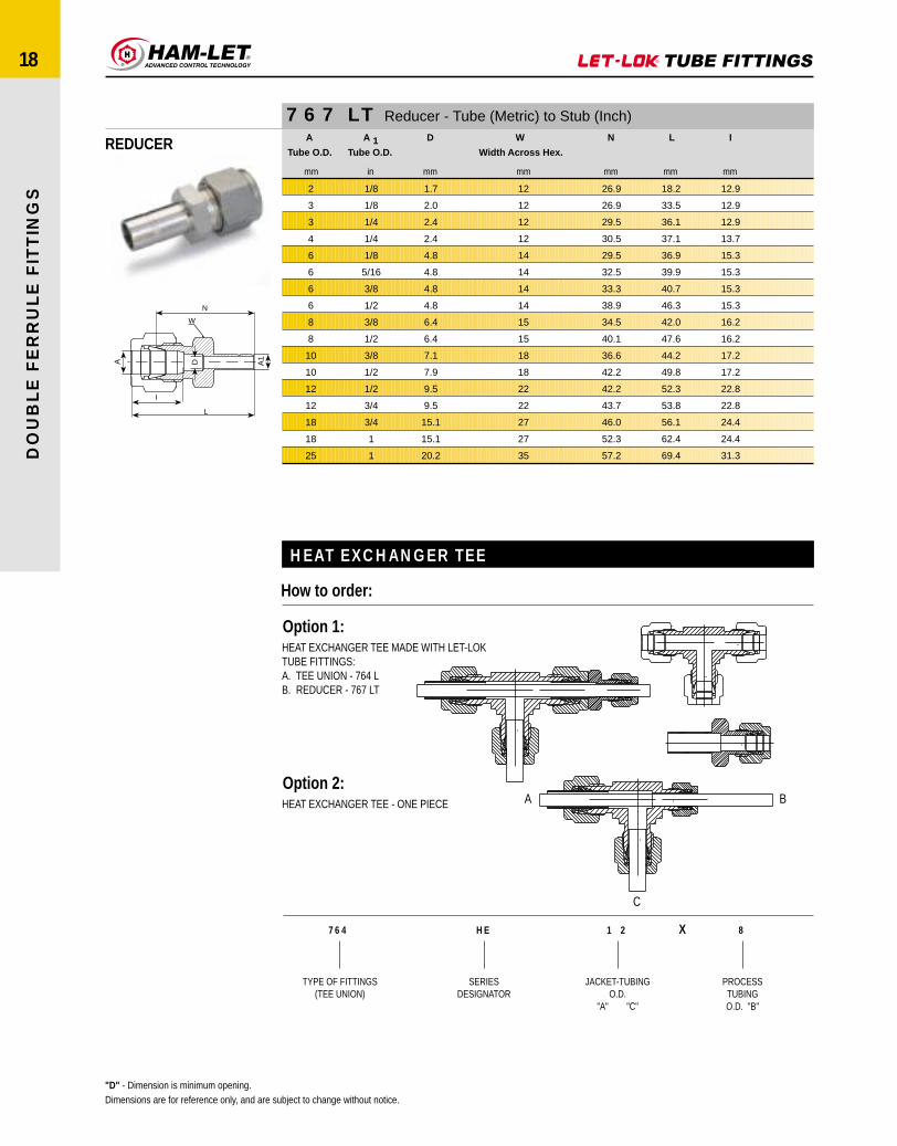
X
TYPE OF FITTINGS(TEE UNION)
764
SERIESDESIGNATOR
HE
JACKET-TUBINGO.D.
"A" "C"
1 2
PROCESSTUBINGO.D. "B"
8
HEAT EXCHANGER TEE
How to order:
Option 1:HEAT EXCHANGER TEE MADE WITH LET-LOKTUBE FITTINGS:A. TEE UNION - 764 LB. REDUCER - 767 LT
Option 2:HEAT EXCHANGER TEE - ONE PIECE A B
C
767 LT Reducer - Tube (Metric) to Stub (Inch)
REDUCER
mmmminmm mmmmmm
A
Tube O.D.
A 1Tube O.D.
D W
Width Across Hex.
N L I
"D" - Dimension is minimum opening.Dimensions are for reference only, and are subject to change without notice.
12
12
12
12
14
14
14
14
15
15
18
18
22
22
27
27
35
2
3
3
4
6
6
6
6
8
8
10
10
12
12
18
18
25
1/8
1/8
1/4
1/4
1/8
5/16
3/8
1/2
3/8
1/2
3/8
1/2
1/2
3/4
3/4
1
1
1.7
2.0
2.4
2.4
4.8
4.8
4.8
4.8
6.4
6.4
7.1
7.9
9.5
9.5
15.1
15.1
20.2
26.9
26.9
29.5
30.5
29.5
32.5
33.3
38.9
34.5
40.1
36.6
42.2
42.2
43.7
46.0
52.3
57.2
18.2
33.5
36.1
37.1
36.9
39.9
40.7
46.3
42.0
47.6
44.2
49.8
52.3
53.8
56.1
62.4
69.4
12.9
12.9
12.9
13.7
15.3
15.3
15.3
15.3
16.2
16.2
17.2
17.2
22.8
22.8
24.4
24.4
31.3

W
I
A A1
L
N
D
DO
UB
LE
FE
RR
UL
E F
ITT
ING
S
19
767 LT Reducer - Tube (Inch) to Stub (Inch)
REDUCER
Reducing port connector 767LM Reducer tube to stub 767 LT
ASSEMBLY INSTRUCTIONS
* Supplied assembled on tube stub end (A1) Nut+Front & Back Ferrule. Tighten the Nut on body 1/2 a turn with wrench. low friction paste, See page 5."D" - Dimension is minimum opening.Dimensions are for reference only, and are subject to change without notice.
1/4 TURN11/4 TURN
11/4 TURN
.34
.34
.50
.50
.50
.50
.50
.54
.60
.60
.60
.60
.60
.60
.60
.60
.60
.64
.64
.66
.66
.66
.66
.66
.90
.90
.90
.90
.90
.90
.96
.96
.96
.96
.96
1.23
1.23
1.62
8.6
8.6
12.7
12.7
12.7
12.7
12.7
13.7
13.7
15.2
15.2
15.2
15.2
15.2
15.2
15.2
15.2
16.3
16.3
16.8
16.8
16.8
16.8
16.8
22.9
22.9
22.9
22.9
22.9
22.9
24.4
24.4
24.4
24.4
24.4
31.2
31.2
41.10
in mm
I
1.15
1.24
1.14
1.35
1.42
1.48
1.74
1.37
1.46
1.45
1.48
1.54
1.57
1.60
1.82
1.89
1.88
1.65
1.87
1.63
1.70
1.91
1.98
1.98
1.77
1.84
2.06
2.12
2.12
2.37
2.15
2.21
2.40
2.15
2.46
3.17
3.51
4.10
29.21
31.50
28.96
34.29
36.06
37.59
44.20
34.80
37.08
36.83
37.59
39.11
39.87
40.64
46.22
48.00
47.75
41.91
47.49
41.40
43.18
48.51
50.29
50.29
44.96
46.74
52.32
53.84
53.84
60.19
54.61
56.13
60.96
54.61
62.48
80.52
89.15
104.1
in mm
L
1.00
1.09
0.88
1.09
1.16
1.22
1.48
1.11
1.20
1.16
1.19
1.25
1.28
1.31
1.53
1.60
1.59
1.36
1.58
1.34
1.41
1.62
1.69
1.69
1.37
1.44
1.66
1.72
1.72
1.97
1.75
1.81
2.00
1.75
2.06
2.69
3.03
3.23
25.40
27.68
22.35
27.68
29.46
30.98
37.59
28.19
30.48
29.46
30.22
31.75
32.51
33.27
38.86
40.64
40.39
34.54
40.13
34.03
35.81
41.14
42.92
42.92
34.80
36.58
42.16
43.68
43.68
50.03
44.45
45.97
50.80
44.45
52.32
68.33
76.96
82.00
in mm
N
5/16
5/16
7/16
7/16
7/16
7/16
9/16
7/16
7/16
1/2
1/2
1/2
1/2
1/2
9/16
11/16
13/16
9/16
9/16
5/8
5/8
5/8
11/16
13/16
13/16
13/16
13/16
13/16
13/16
1-1/16
15/16
15/16
1-1/16
1-1/16
1-1/16
1-3/8
1-5/8
1-3/4
7.93
7.93
11.11
11.11
11.11
11.11
14.28
11.11
11.11
12.70
12.70
12.70
12.70
12.70
14.28
17.46
20.63
14.28
14.28
15.87
15.87
15.87
17.46
20.63
20.63
20.63
20.63
20.63
20.63
26.98
23.81
23.81
26.98
26.98
26.98
34.93
41.28
44.90
in mm
Hex.
WWidth Across
.05
.05
.03
.09
.09
.09
.09
.08
.12
.08
.12
.19
.19
.19
.19
.19
.19
.25
.25
.19
.28
.28
.28
.28
.19
.28
.39
.41
.41
.41
.50
.50
.50
.39
.62
.88
.88
1.09
1.27
1.27
0.76
2.28
2.28
2.28
2.28
2.03
3.04
2.03
3.04
4.82
4.82
4.82
4.82
4.82
4.82
6.35
6.35
4.22
7.11
7.11
7.11
7.11
4.82
7.11
9.91
10.41
10.41
10.41
12.70
12.70
12.70
9.91
15.75
22.35
22.35
27.7
in mm
D
1/8
1/4
1/16
3/16
1/4
3/8
1/2
1/8
1/4
1/8
3/16
1/4
5/16
3/8
1/2
5/8
3/4
3/8
1/2
1/4
3/8
1/2
5/8
3/4
1/4
3/8
1/2
5/8
3/4
1
3/4
7/8
1
1/2
1
*1-1/4
*1-1/2
*1-1/2
3.17
6.35
1.58
4.76
6.35
9.52
12.70
3.17
6.35
3.17
4.76
6.35
7.93
9.52
12.70
7.93
19.05
9.52
12.70
6.35
9.52
12.70
15.87
19.05
6.35
9.52
12.70
15.87
19.05
25.40
19.05
22.22
25.40
12.70
25.40
31.75
38.10
38.1
in mm
A 1Tube O.D.
1/16
1/16
1/8
1/8
1/8
1/8
1/8
3/16
3/16
1/4
1/4
1/4
1/4
1/4
1/4
1/4
1/4
5/16
5/16
3/8
3/8
3/8
3/8
3/8
1/2
1/2
1/2
1/2
1/2
1/2
5/8
5/8
5/8
3/4
3/4
1
1
1-1/4
1.58
1.58
3.17
3.17
3.17
3.17
3.17
4.76
4.76
6.35
6.35
6.35
6.35
6.35
6.35
6.35
6.35
7.93
7.93
9.52
9.52
9.52
9.52
9.52
12.70
12.70
12.70
12.70
12.70
12.70
15.87
15.87
15.87
19.05
19.05
25.40
25.40
31.75
in mm
ATube O.D.

M
A1
D A J
L
N
DO
UB
LE
FE
RR
UL
E F
ITT
ING
S
20
767 LM Reducing Port Connector - Connects Two LET-LOK® Ports
REDUCING PORTCONNECTOR mm mm mm mm mm mm mm
ATube O.D.
A 1Tube O.D.
D N L J M
6
8
10
10
12
12
12
16
3
6
6
8
6
8
10
12
2.2
4.6
4.6
6.4
4.6
6.4
7.7
9.1
13.5
15.7
15.7
16.8
15.7
16.8
17.5
23.1
22.6
24.7
25.0
25.8
29.1
29.8
30.4
36.2
9.0
11.0
13.1
13.1
15.0
15.0
15.0
19.0
3.2
3.1
3.4
3.1
3.6
3.4
3.1
3.4
767 LM Reducing Port Connector - Connects Two LET-LOK® PortsA
Tube O.D.A 1
Tube O.D.D N L J M
in mm in mm in mm in mm in mm in mm in mm
1/8
1/4
1/4
3/8
3/8
1/2
1/2
3/4
3.17
6.35
6.35
9.52
9.52
12.70
12.70
19.05
1/16
1/16
1/8
1/8
1/4
1/4
3/8
1/2
1.58
1.58
3.17
3.17
6.35
6.35
9.52
12.70
.03
.03
.09
.09
.19
.19
.28
.39
0.76
0.76
2.28
2.28
4.82
4.82
7.11
9.90
.34
.34
.53
.53
.62
.62
.69
.91
8.64
8.64
13.46
13.46
15.75
15.75
17.52
23.11
.68
.71
.89
.91
.98
1.15
1.20
1.44
17.27
18.03
22.60
23.11
24.90
29.21
30.48
36.58
.24
.37
.37
.50
.50
.62
.62
.87
6.10
9.40
9.40
12.70
12.70
15.75
15.75
22.10
.08
.14
.13
.15
.13
.15
.13
.15
2.03
3.55
3.30
3.81
3.30
3.81
3.30
3.81
767 LP Port Connector - Connects Two LET-LOK® Ports
PORT CONNECTOR
A D
L
N
J
mm mm mm mm mm
ATube O.D.
D N L J
3
6
8
10
12
16
18
2.1
4.4
6.2
8.2
9.1
12.7
13.9
15.7
18.7
20.0
20.2
26.0
27.6
27.6
22.2
24.6
25.9
26.1
35.8
37.4
37.4
6.0
9.0
11.0
13.1
15.0
19.0
21.1
767 LP Port Connector - Connects Two LET-LOK® PortsA
Tube O.D.D N L J
in mm in mm in mm in mm in mm
1/16
1/8
1/4
5/16
3/8
1/2
3/4
1
1.58
3.17
6.35
7.93
9.52
12.70
19.05
25.40
.03
.09
.19
.25
.30
.39
.59
.80
0.76
2.28
4.82
6.35
7.62
9.90
14.58
20.32
.42
.62
.74
.79
.80
1.02
1.09
1.36
10.66
15.75
18.80
20.06
20.32
25.90
27.68
34.54
.54
.88
.97
1.02
1.03
1.41
1.47
1.90
13.72
22.35
24.64
25.90
26.16
35.81
37.34
48.26
.13
.24
.37
.43
.50
.62
.87
1.12
3.30
6.10
9.40
10.92
12.70
15.75
22.10
28.45
"D" - Dimension is minimum opening.Assembly instructions - see page 19Dimensions are for reference only, and are subject to change without notice.

W
N
A D T
I
L
DO
UB
LE
FE
RR
UL
E F
ITT
ING
S
21
768 L Male Connector - Tube (Metric) Male NPT Thread
MALE CONNECTOR ATube O.D.
T(NPT)
D WWidth Across Hex.
N L I
mmmm inch mm mm mm mm
3
3
4
4
6
6
6
6
8
8
8
8
10
10
10
10
10
12
12
12
12
12
14
14
14
15
16
16
16
18
18
20
20
22
22
25
25
25
1/8
1/4
1/8
1/4
1/8
1/4
3/8
1/2
1/8
1/4
3/8
1/2
1/8
1/4
3/8
1/2
3/4
1/8
1/4
3/8
1/2
3/4
1/4
3/8
1/2
1/2
3/8
1/2
3/4
1/2
3/4
1/2
3/4
3/4
1
1/2
3/4
1
2.4
2.4
2.4
2.4
4.8
4.8
4.8
4.8
4.8
6.4
6.4
6.4
4.8
7.9
7.9
7.9
7.9
4.8
7.1
9.5
9.5
9.5
7.1
9.5
11.1
11.9
9.5
11.9
12.7
11.9
15.1
11.9
15.9
15.9
18.3
11.9
15.9
21.8
12
14
12
14
14
14
18
22
15
15
18
22
18
18
18
22
27
22
22
22
22
27
24
24
24
24
24
24
27
27
27
30
30
30
35
35
35
35
23.9
29.0
24.6
29.7
25.4
30.5
31.0
37.3
26.7
31.2
31.8
31.8
28.7
33.3
33.3
38.1
40.4
28.7
33.3
33.3
30.9
40.4
34.0
34.0
38.9
38.9
34.0
38.9
40.4
40.4
40.4
42.2
42.2
42.2
47.0
45.2
45.2
50.0
30.5
35.6
31.2
36.3
32.8
37.9
38.4
44.7
34.2
38.7
39.3
45.6
36.3
40.9
40.9
46.5
48.0
38.8
43.4
43.4
49.0
50.5
44.1
44.1
49.0
49.0
44.1
49.0
50.5
50.5
50.5
52.3
52.3
52.3
57.1
57.5
57.5
62.3
12.9
12.9
13.7
13.7
15.3
15.3
15.3
15.3
16.2
16.2
16.2
16.2
17.2
17.2
17.2
17.2
19.5
22.8
22.8
22.8
22.8
22.8
22.8
22.8
22.8
24.4
24.4
24.4
24.4
24.4
24.4
26.0
26.0
26.0
26.0
31.3
31.3
31.3
ThermoelementTo order:Use catalog number of the selected fittingand add suffix TC.Example: 768 L ss 1/4 x 1/4 TC
THERMOCOUPLE - CONNECTORS
"D" - Dimension is minimum opening.Dimensions are for reference only, and are subject to change without notice.

W
N
A D T
I
L
768 L Male Connector - Tube (Inch) Male NPT Thread
MALE CONNECTORA
Tube O.D.T
(NPT)D W
Width AcrossHex.
N L I
inin mm in mm in mm in mm in mm in mm
1/16
1/16
1/8
1/8
1/8
3/16
3/16
1/4
1/4
1/4
1/4
1/4
5/16
5/16
3/8
3/8
3/8
3/8
3/8
1/2x1/8
1/2
1/2
1/2
1/2
1/2x1
5/8
5/8
5/8
3/4
3/4
3/4
7/8
1
1
1.58
1.58
3.17
3.17
3.17
4.76
4.76
6.35
6.35
6.35
6.35
6.35
7.93
7.93
9.52
9.52
9.52
9.52
9.52
12.70
12.70
12.70
12.70
12.70
12.70
15.87
15.87
15.87
19.05
19.05
19.05
22.22
25.40
25.40
1/16
1/8
1/16
1/8
1/4
1/8
1/4
1/16
1/8
1/4
3/8
1/2
1/8
1/4
1/8
1/4
3/8
1/2
3/4
1/8
1/4
3/8
1/2
3/4
1
3/8
1/2
3/4
1/2
3/4
1
3/4
3/4
1
.05
.05
.09
.09
.09
.12
.12
.12
.19
.19
.19
.19
.19
.25
.19
.28
.28
.28
.28
.19
.28
.38
.41
.41
.41
.38
.47
.50
.50
.62
.62
.72
.72
.88
1.27
1.27
2.28
2.28
2.28
3.04
3.04
3.04
4.82
4.82
4.82
4.82
4.82
6.35
4.82
7.11
7.11
7.11
7.11
4.82
7.11
9.65
10.41
10.41
10.41
9.65
11.90
12.70
12.70
15.74
15.74
18.28
18.28
22.35
5/16
7/16
7/16
7/16
9/16
7/16
9/16
1/2
1/2
9/16
11/16
7/8
9/16
9/16
5/8
5/8
11/16
7/8
1-1/16
13/16
13/16
13.16
7/8
1-1/16
1 3/8
15/16
15/16
1-1/16
1-1/16
1-1/16
13/8
1-3/16
1-3/8
1-3/8
7.93
11.11
11.11
11.11
14.28
11.11
14.28
12.70
12.70
14.28
17.46
22.22
14.28
14.28
15.87
15.87
17.46
22.22
26.98
20.63
20.63
20.63
22.22
26.98
34.92
23.81
23.81
26.98
26.98
26.98
34.92
30.16
34.92
34.92
.78
.88
.91
.94
1.14
.97
1.17
1.00
1.00
1.20
1.22
1.47
1.05
1.23
1.10
1.28
1.28
1.52
1.59
1.13
1.31
1.31
1.53
1.59
1.85
1.34
1.53
1.59
1.59
1.59
1.85
1.59
1.78
1.97
19.81
22.35
23.11
23.8
28.95
24.53
29.72
25.40
25.40
30.50
30.78
37.34
26.67
31.24
27.90
32.51
32.51
38.90
40.38
28.70
33.27
33.27
38.90
40.38
47.00
34.03
38.86
40.38
40.38
40.38
47.00
40.38
45.21
50.03
.93
1.03
1.17
1.17
1.40
1.23
1.43
1.29
1.29
1.49
1.51
1.76
1.34
1.52
1.38
1.57
1.57
1.82
1.88
1.53
1.71
1.71
1.93
1.99
2.25
1.74
1.93
1.99
1.99
1.99
2.25
1.99
2.26
2.45
23.62
26.1
29.71
29.71
35.56
31.24
36.32
32.76
32.76
37.85
38.35
44.70
34.03
38.60
35.05
39.87
39.87
46.23
47.75
38.86
43.43
43.43
49.02
50.54
57.15
44.19
49.02
50.54
50.54
50.54
57.15
50.54
57.40
62.23
.34
.34
.50
.50
.50
.54
.54
.60
.60
.60
.60
.60
.64
.64
.66
.66
.66
.66
.66
.90
.90
.90
.90
.96
.96
.96
.96
.96
.96
.96
.96
1.02
1.23
1.23
8.6
8.6
12.7
12.7
12.7
13.7
13.7
15.2
15.2
15.2
15.2
15.2
16.2
16.2
16.8
16.8
16.8
16.8
16.8
22.9
22.9
22.9
22.9
22.9
22.9
24.4
24.4
24.4
24.4
24.4
24.4
25.9
31.2
31.2
• 60° Thread angle• Pitch measured in inches• Truncation of root and crest are flat• Taper angle 1° 47'
American Standard Pipe Thread (NPT).NPT (National Pipe Tapered) is made tospecifications outlined in ASNI B1.20.1
1°47
inch
P 60°Reference Specifications: Normen:
"D" - Dimension is minimum opening.Dimensions are for reference only, and are subject to change without notice.
DO
UB
LE
FE
RR
UL
E F
ITT
ING
S
22

W
N
A D T K
I
L
M
DO
UB
LE
FE
RR
UL
E F
ITT
ING
S
23
768 LG Male Connector ISO Parallel Thread
MALE CONNECTORmm mmmmmm in mm mm mmmm
ATube O.D.
T(ISO)
D K WWidth Across Hex.
N M L I
2
3
3
4
6
6
6
6
8
8
8
8
10
10
10
12
12
12
12
16
16
18
18
20
20
22
22
25
25
G-1/8
G-1/8
G-1/4
G-1/8
G-1/8
G-1/4
G-3/8
G-1/2
G-1/8
G-1/4
G-3/8
G-1/2
G-1/4
G-3/8
G-1/2
G-1/4
G-3/8
G-1/2
G-3/4
G-3/8
G-1/2
G-1/2
G-3/4
G-1/2
G-3/4
G-3/4
G-1
G-3/4
G-1
1.7
2.4
2.4
2.4
4.0
4.8
4.8
4.8
4.0
6.4
6.4
6.4
5.9
7.9
7.9
5.9
7.9
9.5
9.5
7.9
11.9
11.9
15.1
11.9
15.9
15.9
18.3
15.9
19.8
13.8
13.8
18.0
13.8
13.8
18.0
21.8
26.0
13.8
13.8
21.8
26.0
18.0
21.8
26.0
18.0
21.8
26.0
32.0
21.8
26.0
26.0
32.0
26.0
32.0
32.0
39.0
32.0
39.0
14.0
14.0
19.0
14.0
14.0
19.0
22.0
27.0
15.0
19.0
22.0
27.0
19.0
22.0
27.0
22.0
22.0
27.0
35.0
24.0
27.0
27.0
35.0
30.0
35.0
35.0
41.0
35.0
41.0
23.4
23.4
28.7
24.1
24.9
30.2
31.5
37.3
25.7
31.0
32.3
38.1
31.8
33.0
38.9
32.5
33.0
38.9
42.7
33.8
38.9
38.9
42.7
40.4
42.7
42.7
45.2
45.2
47.8
7.1
7.1
11.2
7.1
7.1
11.2
11.2
14.2
7.1
11.2
11.2
14.2
11.2
11.2
14.2
11.2
11.2
14.2
15.7
11.2
14.2
14.2
15.7
14.2
15.7
15.7
18.3
15.7
18.3
30.0
30.0
35.3
30.7
24.9
37.6
38.9
44.7
33.2
38.5
39.8
45.6
39.4
40.6
46.5
42.6
43.1
49.0
52.8
43.9
49.0
49.0
52.8
50.5
52.8
52.8
55.3
57.5
60.1
12.9
12.9
12.9
13.7
15.3
15.3
15.3
15.3
16.2
16.2
16.2
16.2
17.2
17.2
17.2
22.8
22.8
22.8
22.8
24.4
24.4
24.4
24.4
26.0
26.0
26.0
26.0
31.3
31.3
Reference Specifications:55°
inch
P
DINBSJISISO
- ISO 228/1- 2779- BO202- 228/1-BSP-P
• 55° Thread angle• Pitch measured in inches• Truncation of root and crest are round• Diameter measured in inches
"D" - Dimension is minimum opening.Dimensions are for reference only, and are subject to change without notice.

W
N
A D T
I
L
DO
UB
LE
FE
RR
UL
E F
ITT
ING
S
24
768 LR Male Connector ISO Tapered Thread
MALE CONNECTOR
DINBSJISISO
Reference Specifications: Normen:
- ISO 2999- 21- BO203- 7/1-BSP-T
• 55° Thread angle• Pitch measured in millimeters• Truncation of root and crest are round• Taper angle 1°47'
1°47
P 55°
2
3
3
4
4
6
6
6
6
8
8
8
8
10
10
10
10
12
12
12
12
15
16
16
16
16
18
18
20
20
22
22
25
25
R-1/8
R-1/8
R-1/4
R-1/8
R-1/4
R-1/8
R-1/4
R-3/8
R-1/2
R-1/8
R-1/4
R-3/8
R-1/2
R-1/8
R-1/4
R-3/8
R-1/2
R-1/4
R-3/8
R-1/2
R-3/4
R-1/2
R-1/4
R-3/8
R-1/2
R-3/4
R-1/2
R-3/4
R-1/2
R-3/4
R-3/4
R-1
R-3/4
R-1
1.7
2.4
2.4
2.4
2.4
4.8
4.8
4.8
4.8
4.8
6.4
6.4
6.4
4.8
7.9
7.9
7.9
7.1
9.5
9.5
9.5
11.9
7.1
9.5
11.9
12.7
11.9
15.1
11.9
15.9
15.9
18.3
15.9
21.8
12
12
14
12
14
14
14
18
22
15
15
18
22
18
18
18
22
22
22
22
27
24
24
24
24
27
27
27
30
30
30
35
35
35
23.9
23.9
29.0
24.6
29.7
25.4
30.5
31.0
37.3
26.7
31.2
31.8
38.1
28.7
33.3
33.3
38.9
33.3
33.3
38.9
40.4
38.9
34.0
34.0
38.9
40.4
40.4
40.4
42.2
42.2
42.2
47.0
45.2
50.0
30.5
30.5
35.6
31.2
36.3
32.8
37.9
38.4
44.7
34.2
38.7
39.2
45.5
36.3
40.9
40.9
46.5
43.4
43.4
49.0
50.5
49.0
44.1
44.1
49.0
50.5
50.5
50.5
52.3
52.3
52.3
57.1
57.5
62.3
12.9
12.9
12.9
13.7
15.3
15.3
15.3
15.3
15.3
16.2
16.2
16.2
16.2
17.2
17.2
17.2
17.2
22.8
22.8
22.8
22.8
24.4
24.4
24.4
24.4
24.4
24.4
24.4
26.0
26.0
26.0
26.0
31.3
31.3
"D" - Dimension is minimum opening.Dimensions are for reference only, and are subject to change without notice.
mm mm mminmm mm mm
ATube O.D.
T(ISO)
D WWidth Across Hex.
N L I

W
N
A D T K
I
L
H
DO
UB
LE
FE
RR
UL
E F
ITT
ING
S
25
768 LOK Male Connector ISO Parallel Thread
MALE CONNECTOR
DINBSJISISO
Reference Specifications:Normen:
- ISO 228/1- 2779- BO202- 228/1-BSP-P
mm in mm mm mm mmmm mm mm
ATube O.D.
T(P-ISO)
D K WWidth Across Hex.
H N L I
3
3
4
6
6
6
6
8
8
8
8
10
10
10
12
12
12
12
15
16
16
18
18
20
20
22
22
25
25
G1/8A
G1/4A
G1/8A
G1/8A
G1/4A
G3/8A
G1/2A
G1/8A
G1/4A
G3/8A
G1/2A
G1/4A
G3/8A
G1/2A
G1/4A
G3/8A
G1/2A
G3/4A
G1/2A
G3/8A
G1/2A
G1/2A
G3/4A
G1/2A
G3/4A
G3/4A
G1A
G3/4A
G1A
2.4
2.4
2.4
4.0
4.8
4.8
4.8
4.0
6.4
6.4
6.4
5.9
7.9
7.9
5.9
7.9
9.5
9.5
11.9
7.9
11.9
11.9
15.1
11.9
15.9
15.9
18.3
15.9
19.8
13.8
18.0
13.8
13.8
18.0
21.8
26.0
13.8
18.0
21.8
26.0
18.0
21.8
26.0
18.0
21.8
26.0
32.0
26.0
21.8
26.0
26.0
32.0
26.0
32.0
32.0
39.0
32.0
39.0
14
19
14
14
19
22
27
15
19
22
27
19
22
27
22
22
27
35
27
24
27
27
35
30
35
35
40
35
40
7.1
11.2
7.1
7.1
11.2
11.2
14.2
7.1
11.2
11.2
14.2
11.2
11.2
14.2
11.2
11.2
14.2
15.7
14.2
11.2
14.2
14.2
15.7
14.2
15.7
15.7
18.3
15.7
18.3
23.4
28.7
24.1
24.9
30.2
31.5
37.3
25.7
31.0
32.3
38.1
31.8
33.0
38.9
32.5
33.0
38.9
42.7
38.9
33.8
38.9
38.9
42.7
40.4
42.7
42.7
45.2
45.2
47.8
30.0
35.3
30.7
32.3
37.6
38.9
44.7
33.2
38.5
39.8
45.6
39.4
40.6
46.5
42.6
43.1
49.0
52.8
49.0
43.9
49.0
49.0
52.8
50.5
52.8
52.8
55.3
57.5
60.1
12.9
12.9
13.7
15.3
15.3
15.3
15.3
16.2
16.2
16.2
16.2
17.2
17.2
19.5
17.2
22.8
22.8
22.8
22.8
22.4
22.4
22.4
22.4
26.0
26.0
26.0
26.0
31.3
31.3
"D" - Dimension is minimum opening.Dimensions are for reference only, and are subject to change without notice.

A
N
D T
I H
L
K
W
A
I
W
H
D T
L
N
DO
UB
LE
FE
RR
UL
E F
ITT
ING
S
26
768 LOB Male Connector SAE/MS Straight Thread Boss*
MALE CONNECTOR
768 LOP O-Seal Male Connector NPT Tapered Thread
MALE CONNECTOR
768 LO O-Seal Male UNF Thread
* Per SAE J1926 and MS 16142. See page 45 for mounting dimensions.** O-rings used are Viton 90 Durometer. Other O-ring materials are available on request. For more technical information see page 45.*** O-rings used are BUNA 70 Durometer.
"D" - Dimension is minimum opening.Dimensions are for reference only, and are subject to change without notice.
1/8
1/4
1/4
1/4
1/4
5/16
3/8
3/8
3/8
3/8
1/2
1/2
1/2
1/2
5/8
5/8
3/4
3/4
7/8
1
1
3.17
6.35
6.35
6.35
6.35
7.93
9.52
9.52
9.52
9.52
12.70
12.70
12.70
12.70
15.87
15/87
19.05
19.05
22.22
25.40
25.40
in
5/16-24
7/16-20
9/16-18
3/4 -16
7/8-14
1/2-20
7/16-20
9/16-18
3/4 -16
7/8-14
9/16-18
3/4 -16
7/8-14
1-1/16-12
3/4 -16
7/8 -14
3/4 -16
1-1/16 -12
1-3/16 -12
1-1/16 -12
1-5/16 -12
TStraight
Thread UN
.09
.19
.19
.19
.19
.25
.20
.28
.28
.28
.28
.41
.41
.41
.42
.50
.42
.62
.72
.66
.88
2.28
4.82
4.82
4.82
4.82
6.4
5.08
7.11
7.11
7.11
7.11
10.41
10.41
10.41
10.66
12.70
10.66
15.74
18.29
16.76
22.35
7/16
9/16
11/16
7/8
1
5/8
5/8
11/16
7/8
1
13/16
7/8
1
1-1/4
15/16
1
1-1/16
1-1/4
1-3/8
1-3/8
1-1/2
11.11
14.28
17.46
22.22
25.4
15.87
15.87
17.46
22.22
25.40
20.63
22.22
25.40
31.75
23.81
25.40
26.98
31.75
34.92
34.92
38.10
in mmAcross Hex
Width
0.92
1.05
1.11
1.18
1.31
1.08
1.11
1.17
1.25
1.37
1.14
1.25
1.37
1.53
1.25
1.38
1.41
1.53
1.53
1.63
1.66
23.37
26.67
28.19
29.97
33.27
27.43
28.19
29.71
31.75
34.80
28.95
31.75
34.80
38.86
31.75
35.05
35.81
38.86
38.86
41.40
42.16
.30
.36
.39
.44
.50
.36
.36
.39
.44
.50
.39
.44
.50
.59
.44
.50
.44
.59
.59
.59
.59
7.62
9.14
9.90
11.17
12.70
9.14
9.14
9.90
11.17
12.70
9.90
11.17
12.70
14.98
11.17
12.70
11.17
14.98
14.98
14.98
14.98
1.18
1.34
1.40
1.47
1.60
1.37
1.40
1.46
1.54
1.66
1.54
1.65
1.77
1.93
1.65
1.78
1.81
1.93
1.93
2.11
2.14
29.97
34.03
35.56
37.33
40.64
34.80
35.56
37.02
39.11
42.16
39.11
41.91
44.96
49.02
41.91
45.21
46.0
49.02
49.02
53.59
54.35
0.50
0.60
0.60
0.60
0.60
0.64
0.66
0.66
0.66
0.66
0.90
0.90
0.90
0.90
0.96
0.96
0.96
0.96
1.02
1.23
1.23
12.7
15.2
15.2
15.2
15.2
16.2
16.8
16.8
16.8
16.8
22.9
22.9
22.9
22.9
22.4
22.4
22.4
22.4
25.9
31.2
31.2
-902
-904
-906
-908
-910
-905
-904
-906
-908
-910
-906
-908
-910
-912
-908
-910
-908
-912
-914
-912
-916
-111
-111
-113
-113
-116
-212
-212
O-Ring***
.50
.60
.60
.66
.66
.66
.90
12.70
15.24
15.24
16.76
16.76
16.76
22.86
I
in mm
1.29
1.39
1.52
1.57
1.63
1.85
1.96
32.76
35.30
38.60
39.88
41.40
46.99
49.78
L
in mm
.28
.28
.38
.38
.41
.53
.53
7.11
7.11
9.65
9.65
10.41
13.46
13.46
H
in mm
1.03
1.10
1.23
1.28
1.34
1.56
1.56
26.16
27.94
31.24
32.51
34.04
39.62
39.62
in mm
N
3/4
3/4
15/16
15/16
1-1/8
1-5/16
1-5/16
19.05
19.05
23.81
23.81
28.57
33.33
33.33
in mm
WWidth
Across Hex.
.74
.74
.93
.93
1.12
1.30
1.30
18.79
18.79
23.62
23.62
28.45
33.02
33.02
K
in mm
.09
.19
.19
.28
.28
.28
.41
2.28
4.82
4.82
7.11
7.11
7.11
10.41
D
in mm
1/8
1/8
1/4
1/4
3/8
1/2
1/2
in
T(NPT)Short
1/8
1/4
1/4
3/8
3/8
3/8
1/2
3.17
6.35
6.35
9.52
9.52
9.52
12.70
in mm
ATube O.D.
1/16
1/8
3/16
1/4
5/16
3/8
1/2
3/4
1
1.58
3.17
4.76
6.35
7.93
9.52
12.70
19.05
25.40
ATube O.D.
in mm
5/16-24
5/16-24
3/8 -24
7/16-20
1/2 -20
9/16-18
3/4 -16
1-1/16-12
1-5/16-12
in
TStraightThread
UNF
.05
.09
.12
.19
.25
.28
.41
.62
.88
1.27
2.28
3.04
4.22
6.35
7.11
10.41
15.74
22.35
D
in mm
.55
.55
.62
.74
.86
.93
1.12
1.49
1.74
14.0
14.0
15.75
18.80
21.84
23.62
28.45
37.85
44.20
K
in mm
9/16
9/16
5/8
3/4
7/8
15/16
1-1/8
1-1/2
1-3/4
14.28
14.28
15.87
19.05
22.22
23.81
28.57
38.10
44.45
WWidthAcross
Hex.in mm
.90
1.02
1.10
1.23
1.32
1.38
1.41
1.65
1.81
22.86
25.90
27.94
31.24
33.52
35.05
35.81
41.91
45.97
N
in mm
.34
.34
.38
.41
.44
.47
.47
.56
.56
8.63
8.63
9.65
10.41
11.17
11.93
11.93
14.22
14.22
H
in mm
1.05
1.28
1.36
1.52
1.61
1.67
1.81
2.05
2.29
26.67
32.51
34.54
38.60
40.89
40.89
45.77
52.07
58.17
L
in mm
.34
.50
.54
.60
.64
.66
.90
.96
1.23
8.63
12.70
13.72
15.24
16.25
16.76
22.86
24.38
31.24
I
in mm
-011
-011
-012
-111
-112
-113
-116
-215
-219
O-Ring***
D
in mm
W N
in mm
H
in mm
L
in mm
I
in mm
O-Ring**ATube O.D.
in mm

w
N
L
A D
I H
F
DO
UB
LE
FE
RR
UL
E F
ITT
ING
S
27
768 LN Male Pipe Weld Connector - Tube (Metric)
MALE PIPE WELDCONNECTOR
768 LN Male Pipe Weld Connector - Tube (Inch)I
in mm
.50
.54
.60
.60
.64
.64
.66
.66
.66
.90
.90
.90
.96
.96
1.23
12.70
13.72
15.24
15.24
16.25
16.25
16.76
16.76
16.76
22.86
22.86
22.86
24.38
24.38
31.24
L
in mm
1.20
1.22
1.30
1.48
1.34
1.52
1.57
1.57
1.82
1.71
1.93
2.00
1.93
2.00
2.45
30.48
30.98
33.02
37.59
34.04
38.61
39.87
39.87
46.22
44.43
49.0
50.80
49.02
50.80
62.23
H
in mm
.38
.38
.38
.56
.38
.56
.56
.56
.75
.56
.75
.75
.75
.75
.94
9.65
9.65
9.65
14.22
9.65
14.22
14.22
14.22
19.05
14.22
19.05
19.05
19.05
19.05
23.87
D
in mm
.09
.12
.19
.19
.20
.25
.28
.28
.28
.41
.41
.41
.50
.62
.88
2.28
3.04
4.82
4.82
5.08
6.35
7.11
7.11
7.11
10.41
10.41
10.41
12.70
15.74
22.35
FPipe Size
in mm
1/8
1/8
1/8
1/4
1/8
1/4
1/4
3/8
1/2
3/8
1/2
3/4
1/2
3/4
1
10.30
10.30
10.30
13.70
10.30
13.70
13.70
17.10
21.34
17.10
21.34
26.67
21.34
26.67
33.40
ATube O.D.
in mm
1/8
3/16
1/4
1/4
5/16
5/16
3/8
3/8
3/8
1/2
1/2
1/2
5/8
3/4
1
3.17
4.76
6.35
6.35
7.93
7.93
9.52
9.52
9.52
12.70
12.70
12.70
15.87
19.05
25.40
mmmmmmmm mmmmmm mm
ATubeO.D.
FPipeSize
D WWidth Across
Hex.
N H L I
3
4
6
6
8
8
8
10
10
10
12
12
12
15
16
18
10.3
10.3
10.3
13.7
10.3
13.7
21.3
13.7
17.1
21.3
13.7
17.1
21.3
21.3
21.3
21.3
2.4
2.4
4.8
4.8
5.1
6.4
6.4
7.1
7.9
7.9
7.1
9.5
9.5
11.9
12.7
13.5
12
12
14
14
15
15
22
18
18
22
22
22
22
24
24
27
23.1
24.1
25.4
30.2
26.7
31.2
37.3
33.3
32.5
38.1
33.3
33.3
38.1
38.9
38.9
40.4
9.7
9.7
9.7
14.2
9.7
14.2
19.0
14.2
14.2
19.0
14.2
14.2
19.0
19.0
19.0
19.0
30.5
31.2
32.8
37.9
34.2
38.7
45.6
40.9
40.9
46.5
43.4
43.4
49.0
49.0
49.0
50.5
12.9
13.7
15.3
15.3
16.2
16.2
16.2
17.2
17.2
17.2
22.8
22.8
22.8
24.4
24.4
24.4
"D" - Dimension is minimum opening.Dimensions are for reference only, and are subject to change without notice.
WWidth
Across Hex.in mm
7/16
7/16
1/2
9/16
9/16
9/16
5/8
11/16
7/8
13/16
7/8
1-1/16
15/16
1-1/16
1-3/8
11.11
11.11
12.70
14.28
14.28
14.28
15.87
17.46
22.22
20.63
22.22
26.98
23.81
26.98
34.92
N
in mm
.94
.96
1.01
1.19
1.05
1.23
1.28
1.28
1.53
1.31
1.53
1.60
1.53
1.60
1.97
23.88
24.38
25.65
30.22
26.67
31.24
32.51
32.51
38.86
33.27
38.86
40.64
38.86
40.64
50.03

W
I
A D
T
E
E1
N
TUBE SOCKETWELD UNION
W
D
C
H
N
F
I
A A
L
DO
UB
LE
FE
RR
UL
E F
ITT
ING
S
28
MALE ELBOW
768 LW Tube socket weld union
769 L Male Elbow - Tube (Metric) Male NPT Thread
3
3
4
4
6
6
6
6
8
8
8
10
10
10
10
12
12
12
12
15
16
16
16
18
18
20
20
22
22
25
25
1/8
1/4
1/8
1/4
1/8
1/4
3/8
1/2
1/8
1/4
1/2
1/8
1/4
3/8
1/2
1/4
3/8
1/2
3/4
1/2
3/8
1/2
3/4
1/2
3/4
1/2
3/4
3/4
1
3/4
1
2.4
2.4
2.4
2.4
4.8
4.8
4.8
4.8
4.8
6.4
6.4
4.8
7.1
7.9
7.9
7.1
9.5
9.5
9.5
11.9
9.5
11.9
12.7
11.9
15.1
11.9
15.9
15.9
18.3
15.9
21.8
11.1
15.9
11.1
15.9
12.7
12.7
18.5
23.8
15.9
16.0
23.8
17.5
17.5
17.5
23.8
20.5
20.5
24.0
28.6
24.0
24.0
23.8
28.6
28.6
28.6
30.2
30.2
30.2
35.0
35.0
35.0
7/16
5/8
7/16
5/8
1/2
1/2
13/16
15/16
5/8
5/8
15/16
11/16
11/16
13/16
15/16
13/16
13/16
15/16
1-1/8
15/16
15/16
15/16
1-1/8
1-1/8
1-1/8
1-3/16
1-3/16
1-3/16
1-3/8
1-3/8
1-3/8
17.0
18.0
18.8
18.8
19.6
19.6
20.6
24.4
21.3
21.3
25.1
23.9
23.9
20.6
25.9
25.9
25.9
25.9
29.7
27.9
27.9
27.9
29.7
29.7
29.7
34.5
34.5
34.5
34.5
36.8
36.8
23.6
24.6
25.4
25.4
27.0
27.0
29.8
31.8
28.8
28.8
32.6
31.5
31.5
31.5
33.5
36.0
36.0
36.0
39.8
38.0
38.0
38.0
39.8
39.8
39.8
44.6
44.6
44.6
44.6
49.1
49.1
17.8
23.4
18.8
23.4
18.8
23.4
26.2
33.0
19.8
24.4
33.0
21.6
26.2
26.2
33.0
28.2
28.2
33.0
36.8
35.1
30.2
35.1
36.8
36.8
36.8
41.7
41.7
41.7
46.5
41.7
46.5
12.9
12.9
13.7
13.7
15.3
15.3
15.3
15.3
16.2
16.2
16.2
17.2
17.2
17.2
17.2
22.8
22.8
22.8
22.8
24.4
24.4
24.4
24.4
24.4
24.4
26.0
26.0
26.0
26.0
31.3
31.3
ATubeO.D.
T(NPT)
D WWidth Across
Hex.
N E E1 I
mm inin mmmm mm mm mm mm
"D" - Dimension is minimum opening.Dimensions are for reference only, and are subject to change without notice.
N
inch mm
0.88
1.03
1.19
1.22
1.31
1.59
22.35
26.16
30.23
31.00
33.28
40.40
L
inch mm
1.14
1.32
1.48
1.62
1.71
2.07
28.96
33.53
37.60
41.15
43.43
52.58
I
inch mm
0.50
0.60
0.66
0.90
0.96
1.23
12.70
15.20
16.80
22.90
24.40
31.20
H
inch mm
0.25
0.31
0.38
0.50
0.56
0.75
6.35
7.87
9.65
12.7
14.22
19.05
F
inch mm
0.31
0.44
0.62
0.75
1.05
1.31
7.87
11.18
15.75
19.05
26.67
33.27
WHEX FLAT
inch mm
7/16
1/2
5/8
13/16
1-1/16
1-3/8
11.11
12.70
15.88
20.64
27.00
34.93
MIN.OPENING
D
inch mm
0.09
0.19
0.28
0.41
0.62
0.88
2.28
4.80
7.10
10.40
15.80
22.35
C
inch mm
0.34
0.41
0.47
0.47
0.47
0.56
8.64
10.41
11.94
11.94
11.94
14.22
ATubeO.D.
inch mm
1/8
1/4
3/8
1/2
3/4
1
3.17
6.35
9.52
12.70
19.05
25.40

MALE ELBOW
W
I
A D
T
E
N1
N
DO
UB
LE
FE
RR
UL
E F
ITT
ING
S
29
769 L Male Elbow - Tube (Metric) Male NPT Thread
1/16
1/16
1/8
1/8
1/8
3/16
3/16
1/4
1/4
1/4
1/4
5/16
5/16
5/16
3/8
3/8
3/8
3/8
3/8
1/2
1/2
1/2
1/2
5/8
5/8
5/8
3/4
3/4
7/8
1
1
1-1/4
1-1/2
1.58
1.58
3.17
3.17
3.17
4.76
4.76
6.35
6.35
6.35
6.35
7.93
7.93
7.93
9.52
9.52
9.52
9.52
9.52
12.70
12.70
12.70
12.70
15.87
15.87
15.87
19.05
19.05
22.22
25.40
25.40
31.75
38.1
1/16
1/8
1/16
1/8
1/4
1/4
1/8
1/8
1/4
3/8
1/2
1/8
1/4
3/8
1/8
1/4
3/8
1/2
3/4
1/4
3/8
1/2
3/4
3/8
1/2
3/4
1/2
3/4
3/4
3/4
1
1-1/4
1-1/2
.05
.05
.09
.09
.09
.12
.12
.19
.19
.19
.19
.19
.25
.25
.19
.28
.28
.28
.28
.28
.38
.41
.41
.38
.47
.50
.47
.62
.62
.62
.88
1.09
1.34
3/8
7/16
3/8
7/16
5/8
5/8
1/2
1/2
1/2
13/16
15/16
5/8
5/8
13/16
5/8
5/8
13/16
15/16
1/1/8
13/16
13/16
15/16
1-1/8
15/16
15/16
1-1/8
1-1/8
1-1/8
1-3/16
1-3/8
1-3/8
1-11/16
2
9.52
11.11
9.52
11.11
15.9
15.9
12.7
12.70
12.70
20.6
23.8
15.87
15.87
20.6
15.87
15.87
20.6
23.8
28.6
20.63
20.63
23.8
28.6
23.81
23.81
28.6
28.6
28.6
30.2
34.9
34.9
42.9
50.8
.06
.06
.67
.67
.71
.74
.74
.77
.77
.88
.96
.84
.84
.91
.91
.91
.94
1.02
1.17
1.02
1.02
1.02
1.17
1.10
1.10
1.17
1.17
1.17
1.36
1.45
1.45
1.75
2.00
15.24
15.24
17.02
17.02
18.03
18.80
18.8
19.56
19.56
22.35
24.38
21.34
21.34
23.11
23.11
23.11
23.87
25.9
29.71
25.9
25.9
25.9
29.71
27.94
27.94
29.71
29.71
29.71
34.54
36.83
36.83
44.5
50.8
.75
.75
.93
.93
.97
1.00
1.00
1.06
1.06
1.17
1.25
1.13
1.13
1.20
1.20
1.20
1.23
1.31
1.46
1.42
1.42
1.42
1.57
1.50
1.50
1.57
1.57
1.57
1.76
1.93
1.93
2.62
3.07
19.05
19.05
23.62
23.62
24.64
25.40
25.4
26.92
26.92
29.71
31.75
28.7
28.7
30.48
30.48
30.48
31.24
33.28
37.08
36.07
36.07
36.07
39.88
38.1
38.1
39.88
39.88
39.88
44.7
49.02
49.02
66.5
78.0
.70
.70
.70
.70
.92
.92
.74
.74
.92
1.03
1.30
.78
.96
1.03
.82
1.00
1.03
1.30
1.45
1.11
1.11
1.30
1.45
1.19
1.38
1.45
1.45
1.45
1.64
1.64
1.83
1.88
2.38
17.78
17.78
17.78
17.28
23.37
23.37
18.8
18.8
23.37
26.16
33.02
45.21
49.78
26.16
20.83
25.40
26.16
33.02
36.83
28.19
28.19
33.02
36.83
30.23
35.05
36.83
36.83
36.83
41.66
41.66
46.48
47.8
60.5
.34
.34
.50
.50
.50
.54
.54
.60
.60
.60
.60
.64
.64
.64
.66
.66
.66
.66
.66
.90
.90
.90
.90
.96
.96
.96
.96
.96
1.02
1.23
1.23
1.62
1.97
8.6
8.6
12.7
12.7
12.7
13.7
13.7
15.2
15.2
15.2
15.2
16.2
16.2
16.2
14.8
14.8
14.8
14.8
14.8
22.9
22.9
22.9
22.9
24.4
24.4
24.4
24.4
24.4
25.9
31.2
31.2
41.1
50.0
ATubeO.D.
T(NPT)
WWidth Across
Hex.
1.27
1.27
2.28
2.28
2.28
3.04
3.04
4.82
4.82
4.82
4.82
4.82
6.35
6.35
4.82
7.11
7.11
7.11
7.11
7.11
9.65
10.41
10.41
9.61
11.94
12.70
11.94
15.74
15.74
15.74
22.35
27.7
34.0
"D" - Dimension is minimum opening.Dimensions are for reference only, and are subject to change without notice.
in
D N E I
mm in in mm in mm in mm in mm in mm in mm
N1

W
I
A D
T
E
E1
N
I
A
E
E1
D
F
W
H
N
DO
UB
LE
FE
RR
UL
E F
ITT
ING
S
30
769 LR Male Elbow - Tube (Metric) ISO Tapered Thread
MALE ELBOW
MALE PIPE WELD ELBOW
DINBSJISISO
Reference Specifications:Normen:
- 2999- 21- BO203- 7/1-BSP-T
769 LN Male Pipe Weld Elbow
3
3
4
4
6
6
6
6
8
8
8
8
10
10
10
12
12
12
12
12
16
16
18
18
20
20
22
22
25
25
R-1/8
R-1/4
R-1/8
R-1/4
R-1/8
R-1/4
R-3/8
R-1/2
R-1/8
R-1/4
R-3/8
R-1/2
R-1/4
R-3/8
R-1/2
R-1/8
R-1/4
R-3/8
R-1/2
R-3/4
R-3/8
R-1/2
R-1/2
R-3/4
R-1/2
R-3/4
R-3/4
R -1
R-3/4
R -1
2.4
2.4
2.4
2.4
4.8
4.8
4.8
4.8
4.8
6.4
6.4
6.4
7.1
7.9
7.9
4.8
7.1
9.5
9.5
9.5
9.5
11.9
11.9
15.1
11.9
15.9
15.9
18.3
15.9
21.8
11.1
15.9
11.1
15.9
12.7
12.7
20.6
23.5
15.9
15.9
20.6
23.8
17.4
20.6
23.5
20.5
20.5
20.5
24.0
28.6
24.0
24.0
28.6
28.6
30.2
30.2
30.2
35.0
35.0
35.0
7/16
5/8
7/16
5/8
1/2
1/2
13/16
15/16
5/8
5/8
13/16
15/16
11/16
13/16
15/16
13/16
13/16
13/16
15/16
1 1/8
15/16
15/16
1 1/8
1 1/8
1 3/16
1 3/16
1 3/16
1 3/8
1 3/8
1 3/8
17.0
18.0
18.8
18.8
19.6
19.6
22.4
24.4
21.3
21.3
23.1
25.1
23.9
23.9
25.9
25.9
25.9
25.9
25.9
29.7
27.9
27.9
29.7
29.7
34.5
34.5
34.5
34.5
36.8
36.8
23.6
24.6
25.4
25.4
27.0
27.0
29.8
31.8
28.8
28.8
31.3
32.6
31.5
31.5
33.5
36.0
36.0
36.0
36.0
39.8
38.0
38.0
39.8
39.8
44.6
44.6
44.6
44.6
49.1
49.1
17.8
23.4
18.8
23.4
18.8
23.4
26.2
33.0
19.8
24.4
26.2
33.0
26.2
26.2
33.0
23.6
28.2
28.2
33.0
36.8
30.2
35.1
36.8
36.8
41.7
41.7
41.7
46.5
41.7
46.5
12.9
12.9
13.7
13.7
15.3
15.3
15.3
15.3
16.2
16.2
16.2
16.2
17.2
17.2
17.2
22.8
22.8
22.8
22.8
22.8
24.4
24.4
24.4
24.4
26.0
26.0
26.0
26.0
31.3
31.3
"D" - Dimension is minimum opening.Dimensions are for reference only, and are subject to change without notice.
1/4
1/4
3/8
1/2
3/4
6.35
6.35
9.52
12.70
19.05
ATube O.D.
in mm
1/8
1/4
1/4
1/2
3/4
10.80
13.70
13.70
21.34
26.67
FPipe Size
Nom mm
.19
.19
.28
.41
.62
4.82
4.82
7.11
10.41
15.75
D
in mm
1/2
1/2
5/8
13/16
1-1/8
12.70
12.70
15.87
20.64
28.6
WWidth
AcrossHex.
in mm
.77
.77
.91
1.02
1.17
19.56
19.56
23.11
25.91
29.72
N
in mm
.38
.56
.56
.75
.75
7.65
14.22
14.22
19.05
19.05
H
in mm
1.06
1.06
1.20
1.42
1.57
26.92
26.92
30.48
36.06
39.88
E
in mm
.74
.92
1.00
1.30
1.45
18.8
23.37
25.40
33.02
36.83
E1
in mm
7.60
7.60
7.66
8.90
8.90
15.24
15.24
16.76
22.86
24.38
I
in mm
ATubeO.D.
T(ISO)
D WWidth Across
Hex.
N E E1 I
mm ininmm mm mm mm mmmm

I
E1
T
A
W
E
N
D
I
E1
D
H
F
A
W
E
N
DO
UB
LE
FE
RR
UL
E F
ITT
ING
S
31
769 LW Socket Weld Elbow
770 L Female Elbow - Tube (Metric) to Female NPT Thread
SOCKET WELD ELBOW
770 L Female Elbow - Tube (Inch) to Female NPT Thread
FEMALE ELBOW
"D" - Dimension is minimum opening.Dimensions are for reference only, and are subject to change without notice.
1/8
1/4
1/8
1/8
1/4
1/2
1/2
1/8
1/4
1/8
1/4
3/8
1/2
1/4
3/8
1/2
3/8
1/2
1/2
3/4
3/4
3/4
1
T(NPT)
in
.09
.09
.12
.19
.19
.19
.19
.25
.25
.28
.28
.28
.28
.41
.41
.41
.50
.50
.62
.62
.72
.88
.88
2.28
2.28
3.04
4.82
4.82
4.82
4.82
6.35
6.35
7.11
7.11
7.11
7.11
10.41
10.41
10.41
12.70
12.70
15.74
15.74
18.28
22.35
22.35
mmin
D
5/8
13/16
5/8
5/8
13/16
15/16
1-1/8
5/8
13/16
5/8
13/16
15/16
1-1/8
13/16
15/16
1-1/8
15/16
1-1/8
1-1/8
1-3/8
1-3/8
1-3/8
1-11/16
15.87
20.63
15.87
15.87
20.63
23.8
28.6
15.87
20.63
15.87
20.63
23.81
28.6
20.63
23.81
28.6
28.6
28.6
28.6
34.9
34.9
34.92
42.86
mmin
WWidth Across
Hex.
.71
.82
.74
.77
.88
.96
1.07
.84
.91
.75
.88
.88
1.12
.88
.88
1.12
.88
1.12
1.12
1.25
1.25
1.25
1.50
18.03
20.83
18.8
19.56
22.35
24.38
27.18
21.34
23.11
19.05
22.35
22.35
28.45
22.35
22.35
28.44
22.35
28.44
28.44
31.75
31.75
31.75
38.10
mmin
N
.97
1.08
1.02
1.06
1.17
1.25
1.36
1.13
1.20
1.20
1.23
1.31
1.42
1.42
1.42
1.53
1.50
1.57
1.57
1.76
1.76
1.93
2.11
24.64
27.43
25.9
26.92
29.72
31.75
34.54
28.7
30.48
30.48
31.24
33.27
36.07
36.07
36.07
36.86
38.1
39.88
39.88
44.7
44.7
49.02
53.59
mmin
E
.75
.88
.75
.75
.88
.88
1.12
.75
.88
.75
.88
.88
1.12
.88
.88
1.12
.88
1.12
1.12
1.25
1.25
1.25
1.50
19.05
22.35
19.05
19.05
22.35
22.35
28.45
19.05
22.35
19.05
22.35
22.35
28.45
22.35
22.35
28.44
22.35
28.44
28.44
31.75
31.75
31.75
38.10
mmin
E1
.50
.50
.54
.60
.60
.66
.60
.60
.64
.64
.66
.66
.66
.90
.90
.90
.96
.96
.96
.96
1.02
1.23
1.23
12.7
12.7
13.7
15.2
15.2
15.2
15.2
16.2
16.2
16.76
16.76
16.76
16.76
22.9
22.9
22.9
22.9
22.9
22.9
22.9
25.9
31.24
31.24
mmin
I
1/8
1/8
3/16
1/4
1/4
1/4
1/4
5/16
5/16
3/8
3/8
3/8
3/8
1/2
1/2
1/2
5/8
5/8
3/4
3/4
7/8
1
1
3.17
3.17
4.76
6.35
6.35
6.35
6.35
9.52
7.93
7.93
9.52
9.52
9.52
12.70
12.70
12.70
15.87
15.87
19.05
19.05
22.22
25.40
25.40
in mm
A
O.D.Tube
in mm
ATube O.D.
1/4
3/8
1/2
6.35
9.52
12.70
D
in mm
.19
.28
.41
4.82
7.11
10.41
in mm
WWidthAcross
Hex.
1/2
5/8
13/16
12.70
15.87
20.64
F
in mm
1/4
3/8
1/2
6.35
9.50
12.70
N
in mm
.78
.91
1.02
19.81
23.11
25.91
H
in mm
.31
.38
.50
7.87
9.65
12.70
E
in mm
1.07
1.20
1.41
27.17
30.98
35.81
in mm
E1
.78
.91
1.02
19.81
23.11
25.91
I
in mm
0.6
0.66
0.90
15.2
16.76
22.9
mm
ATubeO.D.
in
T(NPT)
mm
D WWidth Across
Hex.mm in mm
N
mm
E
mm
E1
mm
I
6
6
12
10
12
1/8
1/4
1/2
1/4
1/4
4.8
4.8
9.5
7.9
9.5
16.0
20.6
30.0
20.6
20.6
5/8
13/16
1 1/8
13/16
13/16
19.6
22.4
28.6
25.9
25.9
27.0
29.8
38.8
33.5
36.0
19.1
22.4
28.5
22.4
22.4
17.7
17.7
22.8
22.8
22.8
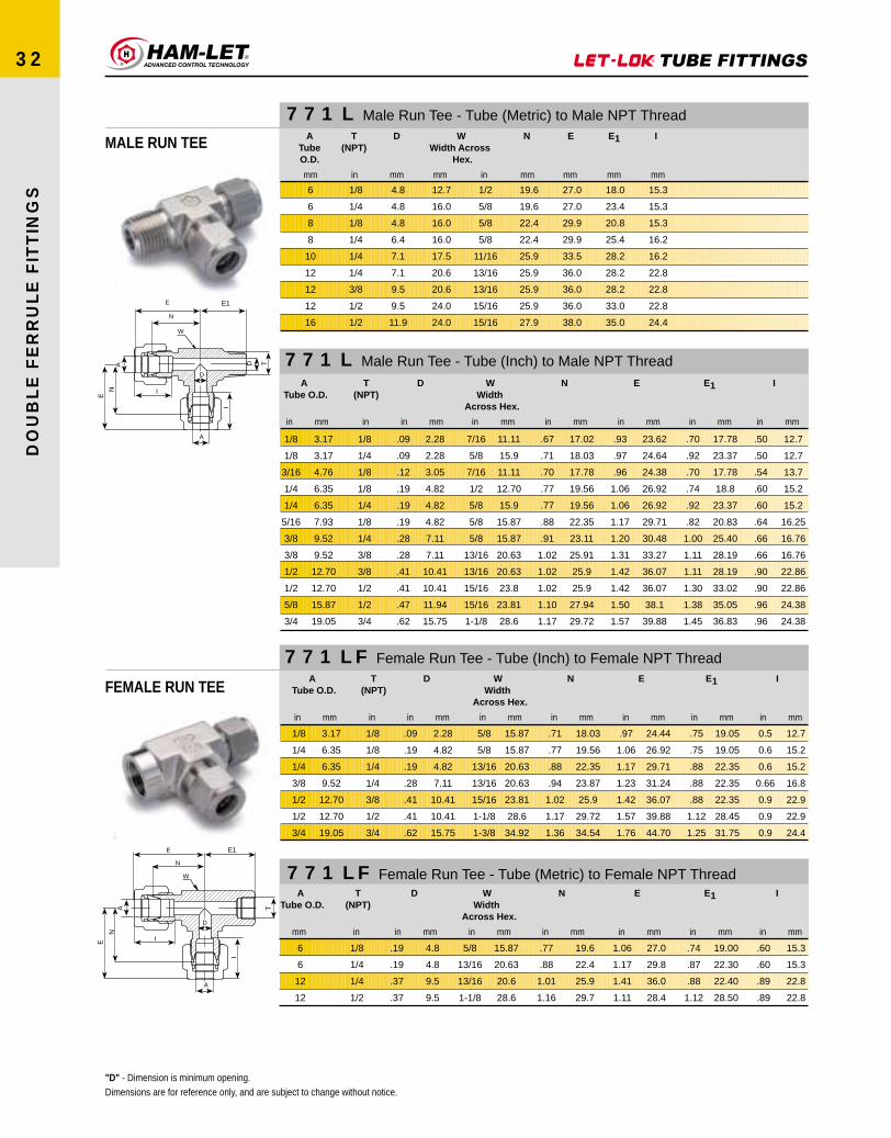
I
E1E
N
D
A
TA
I
W
E
N
I
E1
W
E
N
D
A
DA
I
T
N
E
771 LF Female Run Tee - Tube (Inch) to Female NPT Thread
FEMALE RUN TEE
771 LF Female Run Tee - Tube (Metric) to Female NPT Thread
771 L Male Run Tee - Tube (Metric) to Male NPT Thread
MALE RUN TEE
771 L Male Run Tee - Tube (Inch) to Male NPT Thread
ATube O.D.
mm
6
6
12
12
T(NPT)
in
1/8
1/4
1/4
1/2
D
in mm
.19
.19
.37
.37
4.8
4.8
9.5
9.5
WWidth
Across Hex.
in mm
5/8
13/16
13/16
1-1/8
15.87
20.63
20.6
28.6
N
in mm
.77
.88
1.01
1.16
19.6
22.4
25.9
29.7
E
in mm
1.06
1.17
1.41
1.11
27.0
29.8
36.0
28.4
E1
in mm
.74
.87
.88
1.12
19.00
22.30
22.40
28.50
I
in mm
.60
.60
.89
.89
15.3
15.3
22.8
22.8
ATubeO.D.
T(NPT)
D WWidth Across
Hex.
N E E1 I
mm inmm in mm mm mm mm mm
6
6
8
8
10
12
12
12
16
1/8
1/4
1/8
1/4
1/4
1/4
3/8
1/2
1/2
4.8
4.8
4.8
6.4
7.1
7.1
9.5
9.5
11.9
12.7
16.0
16.0
16.0
17.5
20.6
20.6
24.0
24.0
1/2
5/8
5/8
5/8
11/16
13/16
13/16
15/16
15/16
19.6
19.6
22.4
22.4
25.9
25.9
25.9
25.9
27.9
27.0
27.0
29.9
29.9
33.5
36.0
36.0
36.0
38.0
18.0
23.4
20.8
25.4
28.2
28.2
28.2
33.0
35.0
15.3
15.3
15.3
16.2
16.2
22.8
22.8
22.8
24.4
"D" - Dimension is minimum opening.Dimensions are for reference only, and are subject to change without notice.
.50
.50
.54
.60
.60
.64
.66
.66
.90
.90
.96
.96
12.7
12.7
13.7
15.2
15.2
16.25
16.76
16.76
22.86
22.86
24.38
24.38
I
in mm
.70
.92
.70
.74
.92
.82
1.00
1.11
1.11
1.30
1.38
1.45
17.78
23.37
17.78
18.8
23.37
20.83
25.40
28.19
28.19
33.02
35.05
36.83
E1
in mm
.93
.97
.96
1.06
1.06
1.17
1.20
1.31
1.42
1.42
1.50
1.57
23.62
24.64
24.38
26.92
26.92
29.71
30.48
33.27
36.07
36.07
38.1
39.88
E
in mm
.67
.71
.70
.77
.77
.88
.91
1.02
1.02
1.02
1.10
1.17
17.02
18.03
17.78
19.56
19.56
22.35
23.11
25.91
25.9
25.9
27.94
29.72
N
in mm
7/16
5/8
7/16
1/2
5/8
5/8
5/8
13/16
13/16
15/16
15/16
1-1/8
11.11
15.9
11.11
12.70
15.9
15.87
15.87
20.63
20.63
23.8
23.81
28.6
WWidth
Across Hex.
in mm
.09
.09
.12
.19
.19
.19
.28
.28
.41
.41
.47
.62
2.28
2.28
3.05
4.82
4.82
4.82
7.11
7.11
10.41
10.41
11.94
15.75
D
in mm
1/8
1/4
1/8
1/8
1/4
1/8
1/4
3/8
3/8
1/2
1/2
3/4
in
T(NPT)
1/8
1/8
3/16
1/4
1/4
5/16
3/8
3/8
1/2
1/2
5/8
3/4
3.17
3.17
4.76
6.35
6.35
7.93
9.52
9.52
12.70
12.70
15.87
19.05
ATube O.D.
in mm
ATube O.D.
in mm
1/8
1/4
1/4
3/8
1/2
1/2
3/4
3.17
6.35
6.35
9.52
12.70
12.70
19.05
T(NPT)
in
1/8
1/8
1/4
1/4
3/8
1/2
3/4
D
in mm
.09
.19
.19
.28
.41
.41
.62
2.28
4.82
4.82
7.11
10.41
10.41
15.75
WWidth
Across Hex.
in mm
5/8
5/8
13/16
13/16
15/16
1-1/8
1-3/8
15.87
15.87
20.63
20.63
23.81
28.6
34.92
N
in mm
.71
.77
.88
.94
1.02
1.17
1.36
18.03
19.56
22.35
23.87
25.9
29.72
34.54
E
in mm
.97
1.06
1.17
1.23
1.42
1.57
1.76
24.44
26.92
29.71
31.24
36.07
39.88
44.70
E1
in mm
.75
.75
.88
.88
.88
1.12
1.25
19.05
19.05
22.35
22.35
22.35
28.45
31.75
I
in mm
0.5
0.6
0.6
0.66
0.9
0.9
0.9
12.7
15.2
15.2
16.8
22.9
22.9
24.4
DO
UB
LE
FE
RR
UL
E F
ITT
ING
S
32

I
EE
N
A D
W
E1
N
T
DO
UB
LE
FE
RR
UL
E F
ITT
ING
S
33
772 L Male Branch Tee - Tube (Metric) to Male NPT Thread
772 L Male Branch Tee - Tube (Inch) to Male NPT Thread
MALE BRANCH TEE ATubeO.D.
T(NPT)
D WWidth Across
Hex.
N E E1 I
mm inmm in mm mm mm mm mm
6
6
8
8
10
12
12
12
16
1/8
1/4
1/8
1/4
1/4
1/4
3/8
1/2
1/2
4.8
4.8
4.8
6.4
7.1
7.1
9.5
9.5
11.9
12.7
16.0
15.9
15.9
17.5
20.5
20.5
24.0
24.0
1/2
5/8
5/8
5/8
11/16
13/16
13/16
15/16
15/16
19.6
19.6
22.4
22.4
25.9
25.9
25.9
25.9
28.7
27.0
27.0
29.9
29.9
33.5
36.0
36.0
36.0
38.8
18.8
23.4
20.8
25.4
28.2
28.2
28.2
33.0
35.8
15.3
15.3
16.2
16.2
17.2
17.2
22.8
22.8
24.4
ATube O.D.
in mm
1/8
1/8
3/16
1/4
1/4
5/16
3/8
3/8
1/2
1/2
5/8
3/4
3.17
3.17
4.76
6.35
6.35
7.93
9.52
9.52
12.70
12.70
15.87
19.05
in
T(NPT)
1/8
1/4
1/8
1/8
1/4
1/8
1/4
3/8
3/8
1/2
1/2
3/4
D
in mm
.09
.09
.12
.19
.19
.19
.28
.28
.38
.41
0.47
.62
2.28
2.28
3.04
4.82
4.82
4.82
7.11
7.11
9.65
10.41
11.94
15.75
WWidth
Across Hex.
in mm
7/16
5/8
7/16
1/2
5/8
5/8
5/8
13/16
13/16
15/16
15/16
1-1/8
11.11
15.87
11.1
12.70
15.87
15.87
15.87
20.63
20.63
23.8
23.81
28.6
N
in mm
.67
.71
.70
.77
.77
.88
.91
1.02
1.02
1.02
1.13
1.17
17.02
18.03
17.78
19.56
19.56
22.35
23.11
25.91
25.91
25.96
28.7
29.72
E
in mm
.93
.97
.96
1.06
1.06
1.17
1.20
1.31
1.42
1.42
1.53
1.57
23.62
24.64
24.38
26.9
26.9
29.71
30.48
33.27
36.07
36.07
38.86
39.88
E1
in mm
.70
.92
.70
.74
.92
.82
1.00
1.11
1.11
1.30
1.41
1.45
17.78
23.37
17.78
18.8
23.87
20.83
25.40
28.19
28.19
33.02
35.8
36.83
I
in mm
0.5
0.5
.54
.60
.60
.64
.66
.66
.90
.90
.96
.96
12.7
12.7
13.7
15.2
15.2
16.2
16.76
16.76
22.9
22.9
24.4
24.4
"D" - Dimension is minimum opening.Dimensions are for reference only, and are subject to change without notice.

I
E
N
A D
W
E1
N
E
T
DO
UB
LE
FE
RR
UL
E F
ITT
ING
S
34
772 LF Female Branch Tee - Tube (Metric) to Female NPT Thread
772 LF Female Branch Tee - Tube (Inch) to Female NPT Thread
FEMALE BRANCH TEE
"D" - Dimension is minimum opening.Dimensions are for reference only, and are subject to change without notice.
ATube O.D.
in mm
1/8
1/4
1/4
3/8
1/2
1/2
1/2
5/8
3/4
1
1
3.17
6.35
6.35
9.52
12.70
12.70
12.70
15.87
19.05
25.4
25.4
in
T(NPT)
1/8
1/8
1/4
1/4
3/8
1/4
1/2
1/2
3/4
3/4
1
D
in mm
.09
.19
.19
.28
.41
.41
.41
.50
.62
.88
.88
2.28
4.82
4.82
7.11
10.41
10.41
10.41
12.70
15.74
22.35
22.35
WWidth
Across Hex.
in mm
5/8
5/8
13/16
13/16
15/16
13/16
1-1/8
1-1/8
1-3/8
1-3/8
1-11/16
15.87
15.9
20.63
20.63
23.81
20.63
28.6
28.6
34.9
34.92
42.86
N
in mm
.71
.77
.88
.94
1.02
1.02
1.13
1.13
1.36
1.45
1.63
18.3
19.56
22.35
23.87
25.9
25.91
28.70
28.7
34.54
36.83
41.4
E
in mm
.97
1.06
1.17
1.23
1.42
1.42
1.53
1.53
1.76
1.93
2.11
24.64
26.96
29.71
31.24
36.07
36.06
38.86
38.86
44.7
49.02
53.6
E1
in mm
.75
.75
.88
.88
.88
.88
1.12
1.12
1.25
1.25
1.50
19.05
19.05
22.35
22.35
22.35
22.35
28.45
28.44
31.75
31.75
38.10
I
in mm
31.2
12.7
15.2
15.2
16.8
22.9
22.9
22.9
24.4
24.4
31.2
0.5
0.6
0.6
.66
.90
0.90
0.90
0.96
0.96
1.23
1.23
ATubeO.D.
T(NPT)
D WWidth Across
Hex.
N E E1 I
mm inmm in mm mm mm mm mm
6
6
10
10
12
12
16
1/8
1/4
1/4
3/8
1/4
1/2
1/2
4.8
4.8
7.9
7.9
9.5
9.5
12.7
15.9
20.6
20.6
23.8
20.6
28.6
28.6
5/8
13/16
13/16
15/16
13/16
1-1/8
1-1/8
19.6
22.4
25.9
25.9
25.9
28.7
28.7
27.0
29.8
33.5
33.5
36.0
38.8
38.8
19.0
22.4
22.4
22.4
22.4
28.5
28.4
15.3
15.3
17.2
15.3
22.8
22.8
24.4

L1
L
N1
N
A
W
D A
I
WW W
DO
UB
LE
FE
RR
UL
E F
ITT
ING
S
35
774 L Bulkhead Union - Tube (Inch) to Tube (Inch)
BULKHEAD UNION
774 L Bulkhead Union - Tube (Metric) to Tube (Metric)
774 LF Bulkhead Female Connector - Tube (Inch) to Female NPT Thread
BULKHEAD FEMALECONNECTOR
A
WW1
I
L1
L
N1
N
D T
"D" - Dimension is minimum opening.Dimensions are for reference only, and are subject to change without notice.
.12
.50
.50
.40
.43
.44
.50
.50
.66
.75
3.05
12.70
12.70
10.16
10.92
11.17
12.70
12.70
16.76
19.05
MaxPanel
Thickness
in mm
13/64
21/64
25/64
29/64
33/64
37/64
49/64
57/64
1-1/64
1-21/64
5.16
8.33
9.92
11.50
13.09
14.68
19.44
22.62
25.79
33.73
Panel HoleDrill Size
in mm
.34
.50
.54
.60
.64
.66
.90
.96
.96
1.23
8.6
12.7
13.7
15.2
16.2
16.8
22.9
24.4
24.4
31.2
I
in mm
0.68
1.23
1.26
1.32
1.41
1.45
1.65
1.68
1.87
2.26
17.3
31.24
32.00
33.52
35.81
36.83
41.91
42.67
47.49
57.40
L1
in mm
1.24
2.02
2.11
2.27
2.39
2.45
2.80
2.86
3.11
3.77
31.5
51.30
53.59
57.65
60.70
62.2
71.12
72.64
78.99
95.76
L
in mm
0.53
0.97
1.00
1.03
1.12
1.16
1.25
1.28
1.47
1.78
13.46
24.63
25.40
26.16
28.44
29.46
31.75
32.51
37.33
45.21
N1
in mm
0.94
1.50
1.59
1.69
1.81
1.87
2.00
2.06
2.31
2.81
23.88
38.10
40.38
42.92
45.97
47.5
50.20
52.32
58.67
71.37
N
in mm
5/16
1/2
9/16
5/8
11/16
3/4
15/16
1-1/16
1-3/16
1-5/8
7.93
12.70
14.28
15.87
17.46
19.05
23.81
26.98
30.16
41.27
WWidth
Across Hex.
in mm
.05
.09
.12
.19
.25
.28
.41
.50
.50
.88
1.27
2.28
3.04
4.82
6.35
7.11
10.41
12.7
12.70
22.35
D
in mm
1/16
1/8
3/16
1/4
5/16
3/8
1/2
5/8
3/4
1
1.58
3.17
4.76
6.35
7.93
9.52
12.70
15.87
19.05
25.40
ATube O.D.
in mm
12.7
12.7
10.2
11.2
11.2
12.7
12.7
12.7
16.8
23.9
19.0
MaxPanel
Thickness
mm
8.30
9.90
11.50
13.10
16.25
19.50
22.80
22.80
26.00
29.00
33.70
Panel HoleDrill Size
mm
12.9
13.7
15.3
16.2
17.2
22.8
24.4
24.4
24.4
26.0
31.2
I
mm
31.2
32.0
33.6
36.1
37.0
41.9
42.6
42.6
47.4
53.0
57.5
L1
mm
51.3
53.6
57.7
61.0
63.7
71.0
72.5
72.5
78.9
84.5
96.0
L
mm
24.6
25.4
26.2
28.6
29.4
31.8
32.5
32.5
37.3
42.9
45.2
N1
mm
38.1
40.4
42.9
46.0
48.5
50.8
52.3
52.3
58.7
64.3
71.4
N
mm
14.0
14.0
16.0
18.0
22.0
24.0
27.0
27.0
30.0
35.0
40.0
WWidth
Across Hex.
mm
3
4
6
8
10
12
15
16
18
20
25
ATube O.D.
mm
2.4
2.4
4.8
6.4
7.9
9.5
11.9
12.7
15.1
15.9
21.8
D
mm
1/8
1/8
1/4
1/4
3/8
1/2
t(NPT)
in
1/8
1/4
1/4
3/8
1/2
1/2
3.17
6.35
6.35
9.52
12.70
12.70
ATubeO.D.
in mm
.09
.19
.19
.28
.41
.41
2.28
4.82
4.82
7.11
10.41
10.41
in mm
D
9/16
5/8
3/4
3/4
15/16
1-1/16
14.28
15.87
19.05
19.05
23.81
26.98
WWidth
AcrossHex.
in mm
1.50
1.56
1.75
1.88
2.03
2.22
38.10
39.62
44.45
47.75
51.56
56.38
N
in mm
.97
1.03
1.03
1.16
1.25
1.25
24.63
26.16
26.16
29.46
31.75
31.75
N1
in mm
1.76
1.85
2.04
2.17
2.43
2.62
44.70
46.99
51.81
55.11
61.72
66.54
L
in mm
1.23
1.32
1.32
1.45
1.65
1.65
31.24
33.52
33.52
36.83
41.91
41.91
L1
in mm
0.5
.60
.60
.66
.90
.90
12.7
15.2
15.2
16.8
22.9
22.9
I
in mm
21/64
29/64
29/64
37/64
49/64
49/64
8.33
11.50
11.50
14.68
19.44
19.44
Panel HoleDrill Size
in mm
.50
.40
.40
.44
.50
.50
12.70
10.16
10.16
11.17
12.70
12.70
MaxPanel
Thickness
in mm
1/2
5/8
5/8
3/4
15/16
15/16
12.70
15.87
15.87
19.05
23.81
23.81
in mm
WWidth
AcrossHex.
1

A
W
L1
L
N1
N
TD
W
DO
UB
LE
FE
RR
UL
E F
ITT
ING
S
36
A
W
L1
L
N2
D A1
N1
N
I
W
774 LT Bulkhead Reducer - Tube (Inch) to Tube (Inch)
BULKHEAD REDUCER
774 LM Bulkhead Male Connector - Tube (Metric) to Male NPT Thread
BULKHEAD MALECONNECTOR
774 LM Bulkhead Male Connector - Tube (Inch) to Male NPT Thread
ATubeO.D.
T(NPT)
D WWidth Across Hex.
N N1 L L1 PaneHol
Drill Size
MaxPane
Thicknes
mmmm mminch mm mm mm mm mm mm
6
6
12
1/8
1/4
1/2
4.8
4.8
9.5
16.0
16.0
24.0
42.2
46.0
57.8
26.2
26.2
31.8
49.6
53.4
68.1
33.6
33.6
41.9
11.5
11.5
19.5
10.2
10.2
12.7
"D" - Dimension is minimum opening.Dimensions are for reference only, and are subject to change without notice.
1.23
1.32
1.45
1.65
31.24
33.52
36.83
41.91
in mm
1L
0.5
0.6
0.66
0.9
12.7
15.2
16.8
22.9
in mm
I
1.95
2.19
2.42
2.87
49.53
55.62
61.46
72.89
in mm
L
.53
.62
.69
.91
13.46
15.74
17.52
23.11
N2
in mm
.97
1.03
1.16
1.25
24.63
26.16
29.46
31.75
N1
in mm
1.69
1.90
2.13
2.47
42.92
48.26
54.10
62.73
N
in mm
1/2
5/8
3/4
15/16
12.70
15.87
19.05
23.81
in
WWidth
Across Hex.
mm
.08
.19
.28
.39
2.03
4.82
7.11
9.90
in mm
D
1/8
1/4
3/8
1/2
in
A1
1/8
1/4
3/8
1/2
3.17
6.35
9.52
12.70
in mm
ATube O.D.
in mm
ATubeO.D.
1/8
1/4
1/4
3/8
1/2
1/2
3.17
6.35
6.35
9.52
12.70
12.70
in
T(NPT)
1/8
1/8
1/4
1/4
3/8
1/2
in mm
D
.09
.19
.19
.28
.37
.41
2.28
4.82
4.82
7.11
9.40
10.41
in mm
Hex.
WWidthAcross
1/2
5/8
5/8
3/4
15/16
15/16
12.70
15.87
15.87
19.05
23.81
23.81
in mm
N
1.57
1.66
1.81
1.97
2.09
2.31
39.87
42.16
45.97
50.03
53.09
58.8
in mm
N1
.97
1.03
1.03
1.16
1.25
1.25
24.63
26.16
26.16
29.46
31.75
31.75
in mm
L
1.83
1.95
2.10
2.26
2.49
2.71
46.48
49.53
53.34
57.40
83.25
68.83
in mm
MaxPanel
Thickness
.50
.40
.40
.44
.50
.50
12.70
10.16
10.16
11.17
12.70
12.70
in mm
Panel HoleDrill Size
21/64
29/64
29/64
37/64
49/64
49/64
8.33
11.50
11.50
14.68
19.44
19.44
in mm
L1
1.23
1.32
1.32
1.45
1.65
1.65
31.24
33.52
33.52
36.83
41.91
41.91

DO
UB
LE
FE
RR
UL
E F
ITT
ING
S
37
7102 L Union Cross - All Tubes (Metric)
UNION CROSS
W
I
E E
N N
DA
7102 L Union Cross - All Tubes (Inch)
7108 L Cap - Capping End of Tube (Metric)
CAP
A
W
L
N
I
7108 L Cap - Capping End of Tube (Inch)
ATube O.D.
D WWidth Across Hex.
N E I
mmmm mm mm mm mm
3
6
8
10
12
16
18
20
2.4
4.8
6.4
7.9
9.5
12.7
15.1
15.9
9.5
12.7
15.9
20.6
20.6
23.8
27.0
34.9
15.7
19.6
22.4
25.9
25.9
26.9
28.2
34.5
22.3
27.0
29.9
33.5
36.0
37.0
38.3
44.6
12.9
15.3
16.2
17.2
22.8
24.4
24.4
26.0
ATube O.D.
D WWidth Across
Hex.
N E I
in mm in mm in mm in mm in mm in mm
1/8
1/4
5/16
3/8
1/2
3/4
1
3.17
6.35
7.93
9.52
12.70
19.05
25.40
.09
.19
.25
.28
.41
.62
.88
2.28
4.82
6.35
7.11
10.41
15.74
22.35
3/8
1/2
5/8
5/8
13/16
1-1/16
1-3/8
9.52
12.70
15.87
15.87
20.63
26.98
34.9
.62
.77
.88
.91
1.02
1.17
1.45
15.74
19.56
22.35
23.11
25.9
29.72
36.8
.88
1.07
1.17
1.20
1.42
1.57
1.93
22.35
27.18
29.71
30.48
36.07
39.88
49.02
.50
.60
.64
.66
.90
.96
1.23
12.7
15.2
16.2
16.8
22.9
24.4
31.2
ATube O.D.
WWidth Across Hex.
N L I
mmmm mm mm mm
2
3
4
6
8
10
12
15
16
18
20
22
25
12
12
12
14
15
18
22
24
24
27
30
30
35
13.5
13.5
14.7
15.7
17.0
15.0
19.0
19.8
19.8
21.3
23.9
23.9
26.2
20.1
20.1
21.3
23.1
24.6
26.6
29.1
29.9
29.9
31.4
34.0
34.0
38.5
12.9
12.9
13.7
15.3
16.2
17.2
22.8
24.4
24.4
24.4
26.0
26.0
31.3
ATube O.D.
WWidth Across Hex.
N L I
in mm in mm in mm in mm in mm
1/16
1/8
3/16
1/4
5/16
3/8
1/2
5/8
3/4
7/8
1
1.58
3.17
4.76
6.35
7.93
9.52
12.70
15.87
19.05
22.22
25.40
5/16
7/16
7/16
1/2
9/16
5/8
13/16
15/16
1-1/16
1-3/16
1-3/8
7.93
11.11
11.11
12.70
14.28
15.87
20.63
23.81
26.98
30.16
34.92
.44
.53
.58
.62
.67
.72
.75
.78
.84
.94
1.03
11.17
13.46
14.73
15.74
17.01
18.28
19.05
19.81
21.33
23.88
26.16
.59
.79
.84
.91
.96
1.01
1.15
1.18
1.24
1.34
1.51
14.98
20.06
21.84
23.11
24.38
26.65
29.21
29.97
31.49
34.04
38.35
.34
.50
.54
.60
.64
.66
.90
.96
.96
1.02
1.23
8.6
12.7
13.7
15.2
16.2
16.2
16.8
22.9
24.4
25.9
31.2
"D" - Dimension is minimum opening.Dimensions are for reference only,and are subject to change without notice.

DO
UB
LE
FE
RR
UL
E F
ITT
ING
S
38
7121 L Plug - Plugging Unused Port of Fitting (Metric)
PLUG
W
A
mm mm in
WWidth Across Hex.
A
3
4
6
8
10
12
15
16
18
20
22
25
12
12
14
16
19
22
25
25
30
32
32
38
—
—
9/16
5/8
3/4
7/8
1
1
1-3/16
1-1/4
1-1/4
—
7121 L Plug - Plugging Unused Port of Fitting (Inch)A W
Width Across Hex.
1/16
1/8
3/16
1/4
5/16
3/8
1/2
5/8
3/4
1
1.58
3.17
4.76
6.35
7.93
9.52
12.70
15.87
19.05
25.40
5/16
7/16
1/2
9/16
5/8
11/16
7/8
1
1-1/8
1-1/2
7.93
11.11
12.70
14.28
15.87
17.46
22.22
25.40
28.57
38.10
1/4 TURN (90º)ONLY
PLUG ASSEMBLY INSTRUCTIONS7121L XX XX
"D" - Dimension is minimum opening.Dimensions are for reference only, and are subject to change without notice.
in mm in mm

L
N
T
W
A D
DO
UB
LE
FE
RR
UL
E F
ITT
ING
S
39
739 LF Female Adapter - Tube (Metric) Female Pipe
FEMALE ADAPTERTUBE TO PIPE
739 LF Female Adapter - Tube (Inch) Female Pipe
mm mmmmmm inch in
3
3
4
4
6
6
6
6
8
8
10
10
10
10
12
12
12
16
16
16
20
20
20
22
25
25
1/8
1/4
1/8
1/4
1/8
1/4
3/8
1/2
1/8
1/4
1/8
1/4
3/8
1/2
1/4
3/8
1/2
3/8
1/2
3/4
1/2
3/4
1
3/4
3/4
1
1.8
1.8
2.4
2.4
4.6
4.6
4.6
4.6
6.4
6.4
7.1
7.7
7.7
7.7
9.1
9.5
9.1
12.7
12.7
12.7
15.1
15.1
15.1
17.0
23.7
23.7
14.0
19.0
14.0
19.0
14.0
19.0
22.0
27.0
14.0
19.0
14.0
19.0
22.0
27.0
19.0
22.0
27.0
22.0
27.0
32.0
27.0
32.0
41.0
32.0
32.0
41.0
9/16
3/4
9/16
3/4
9/16
3/4
7/8
1-1/16
9/16
3/4
9/16
3/4
7/8
1-1/16
3/4
7/8
1-1/16
7/8
1-1/16
1 1/4
1-1/16
1-1/4
1-5/8
1-1/4
1-1/4
1-5/8
13.5
13.5
14.2
14.2
15.7
15.7
15.7
15.7
16.5
16.5
17.3
17.3
17.3
17.3
22.8
22.8
22.8
24.4
24.4
24.4
24.4
24.4
24.4
26.2
30.7
30.7
31.3
34.1
32.0
34.8
32.5
37.1
39.6
37.1
34.3
37.6
35.3
38.1
40.1
46.5
43.7
46.7
52.3
48.3
53.9
55.4
53.9
55.4
62.5
57.2
61.7
68.8
ATube O.D.
T(NPT)
D WWidth Across Hex.
N L
in mm in mm in mm in mm in mmin
1/8
1/8
3/16
3/16
1/4
1/4
1/4
1/4
5/16
5/16
3/8
3/8
3/8
3/8
1/2
1/2
1/2
5/8
5/8
5/8
3/4
3/4
3/4
7/8
1
1
3.17
3.17
4.76
4.76
6.35
6.35
6.35
6.35
7.93
7.93
9.52
9.52
9.52
9.52
12.70
12.70
12.70
15.87
15.87
15.87
19.05
19.05
19.05
22.22
25.40
25.40
1/8
1/4
1/8
1/4
1/8
1/4
3/8
1/2
1/8
1/4
1/8
1/4
3/8
1/2
1/4
3/8
1/2
3/8
1/2
3/4
1/2
3/4
1
3/4
3/4
1
.09
.09
.12
.12
.198
.198
.19
.19
.25
.25
.28
.28
.28
.28
.39
.39
.39
.50
.50
.50
.59
.59
.59
.68
.80
.80
2.3
2.3
3.04
3.04
4.83
4.83
4.83
4.83
6.35
6.35
7.11
7.11
7.11
7.11
9.90
9.90
9.90
12.70
12.70
12.70
14.98
14.98
14.98
17.27
20.32
20.32
9/16
3/4
9/16
3/4
9/16
3/4
7/8
1-1/16
9/16
3/4
9/16
3/4
7/8
1-1/16
3/4
7/8
1-1/16
7/8
1-1/16
1-1/4
1-1/16
1-5/16
1-5/8
1-1/4
1-1/4
1-5/8
14.28
19.05
14.28
19.05
14.28
19.05
22.22
26.98
14.28
19.05
14.28
19.05
22.22
26.98
19.05
22.22
26.98
22.22
26.98
31.75
26.98
31.75
41.27
31.75
31.75
41.27
.53
.53
.56
.56
.62
.62
.62
.62
.65
.65
.68
.68
.68
.68
.90
.90
.90
.96
.96
.96
.96
.96
.96
1.03
1.21
1.21
13.46
13.46
14.22
14.22
15.74
15.74
15.74
15.74
16.51
16.51
17.27
17.27
17.27
17.27
22.86
22.86
22.86
24.38
24.38
24.38
24.38
24.38
24.38
26.16
30.73
30.73
1.24
1.39
1.26
1.41
1.30
1.46
1.55
1.79
1.35
1.48
1.35
1.50
1.59
1.84
1.71
1.79
2.04
1.90
2.09
2.18
2.08
2.16
2.30
2.25
2.39
2.53
31.5
35.3
32.00
35.8
33.02
37.08
39.37
45.46
34.29
37.6
34.3
38.10
40.4
46.73
43.43
45.47
51.82
48.26
53.08
55.37
52.8
54.86
58.42
57.15
60.7
64.26
"D" - Dimension is minimum opening.Dimensions are for reference only,and are subject to change without notice.
mm
ATube O.D.
T(NPT)
D WWidth Across Hex.
N L

DO
UB
LE
FE
RR
UL
E F
ITT
ING
S
40
739 LM Male Adapter - Tube (Metric) Male Pipe
MALE ADAPTERTUBE TO PIPE
3
3
4
4
6
6
6
6
8
8
10
10
10
10
12
12
12
16
16
16
20
20
20
22
25
25
1/8
1/4
1/8
1/4
1/8
1/4
3/8
1/2
1/8
1/4
1/8
1/4
3/8
1/2
1/4
3/8
1/2
3/8
1/2
3/4
1/2
3/4
1
3/4
3/4
1
1.8
1.8
2.4
2.4
4.6
4.6
4.6
4.6
6.4
6.4
7.1
7.1
7.7
7.7
7.1
9.5
9.1
12.7
12.7
12.7
15.1
15.1
15.1
17.0
19.6
19.6
11.0
14.0
11.0
14.0
11.0
14.0
17.0
22.0
11.0
14.0
11.0
14.0
17.0
22.0
14.0
17.0
22.0
17.0
22.0
27.0
22.0
27.0
35.0
27.0
27.0
35.0
13.5
13.5
14.2
14.2
15.7
15.7
15.7
15.7
16.5
16.5
17.3
17.3
17.3
17.3
22.9
22.9
22.9
24.4
24.4
24.4
24.4
24.4
24.4
26.2
30.8
30.8
28.5
33.3
29.2
34.0
32.8
38.1
36.3
41.9
31.8
39.1
33.3
39.9
40.6
46.2
46.5
44.5
52.0
46.0
50.1
51.6
50.8
51.6
57.9
53.1
57.9
65.1
739 LM Male Adapter - Tube (Inch) Male Pipe
1/8
1/8
3/16
3/16
1/4
1/4
1/4
1/4
5/16
5/16
3/8
3/8
3/8
3/8
1/2
1/2
1/2
5/8
5/8
5/8
3/4
3/4
3/4
7/8
1
1
3.17
3.17
4.76
4.76
6.35
6.35
6.35
6.35
7.93
7.93
9.52
9.52
9.52
9.52
12.70
12.70
12.70
15.87
15.87
15/87
19.05
19.05
19.05
22.22
25.40
25.40
1/8
1/4
1/8
1/4
1/8
1/4
3/8
1/2
1/8
1/4
1/8
1/4
3/8
1/2
1/4
3/8
1/2
3/8
1/2
3/4
1/2
3/4
1
3/4
3/4
1
.09
.09
.12
.12
.19
.19
.19
.19
.25
.25
.28
.28
.28
.28
.39
.39
.39
.50
.50
.50
.59
.59
.59
.68
.80
.80
2.28
2.28
3.04
3.04
4.83
4.83
4.83
4.83
6.35
6.35
7.11
7.11
7.11
7.11
9.90
9.90
9.90
12.70
12.70
12.70
14.98
14.98
14.98
17.27
20.32
20.32
7/16
9/16
7/16
9/16
7/16
9/16
11/16
7/8
7/16
9/16
7/16
9/16
11/16
7/8
9/16
11/16
7/8
11/16
7/8
1-1/16
7/8
1-1/16
1-3/8
1-1/16
1-1/16
1-3/8
11.11
14.28
11.11
14.28
11.11
14.28
17.46
22.22
11.11
14.28
11.11
14.28
17.46
22.22
14.28
17.46
22.22
17.46
22.22
26.98
22.22
26.98
34.92
26.98
26.98
34.92
.53
.53
.56
.56
.62
.62
.62
.62
.65
.65
.68
.68
.68
.68
.90
.90
.90
.96
.96
.96
.96
.96
.96
1.03
1.21
1.21
13.46
13.46
14.22
14.22
15.74
15.74
15.74
15.74
16.51
16.51
17.27
17.27
17.27
17.27
22.86
22.86
22.86
24.38
24.38
24.38
24.38
24.38
24.38
26.16
30.73
30.73
1.16
1.37
1.19
1.40
1.25
1.46
1.49
1.71
1.29
1.50
1.32
1.53
1.56
1.78
1.75
1.78
20.0
1.81
2.06
2.03
2.06
2.06
2.28
2.09
2.31
2.60
29.46
34.8
30.22
35.56
31.75
37.08
37.85
43.43
32.76
38.1
33.53
38.86
39.62
45.21
44.45
45.21
50.8
50.8
52.34
52.34
52.34
52.34
52.34
52.34
58.67
66.04
"D" - Dimension is minimum opening.Dimensions are for reference only,and are subject to change without notice.
L
N
T-N
PT
A D
W
ATube O.D.
T(NPT)
D WWidth Across Hex.
N L
ATube O.D.
T(NPT)
D WWidth Across Hex.
N L
inin mm in mm in mm in mm in mm
mm mm mmmminmm

L
W
A
AN
L1
B
L
B
D
W
A An
I
L
B
W
A
I
An
L1
B1
D
T
DO
UB
LE
FE
RR
UL
E F
ITT
ING
S
41
761 LFL LET-LOK® to AN Adapter
LET-LOK TO AN ADAPTER L1ATube O.D.
ANTube Flare Size
WWidth Across Hex.
L B
in mm in mm in mm in mm in mm in mm
1/8
1/8
1/4
3/8
1/2
3.17
3.17
6.35
9.52
12.70
1/8
1/4
1/4
3/8
1/2
3.17
6.35
6.35
9.52
12.70
3/8
9/16
9/16
11/16
7/8
9.52
14.28
14.28
17.46
22.22
.73
.75
.84
.98
1.25
18.54
19.05
21.33
24.89
31.75
.54
.62
.62
.72
.85
13.71
15.74
15.74
21.59
21.59
.53
.53
.62
.69
.91
13.46
13.46
15.75
17.53
23.1
762 LFL LET-LOK® to AN Union - Tube (Inch) to Tube (Inch)
LET-LOK TO AN UNION ATube O.D.
ANTube
Flare Size
D WWidth
Across Hex.
B L I TStraighThrea
in mm in mm in mm in mm in mm in mm in mm
1/16
1/8
1/8
1/4
3/8
3/8
1/2
3/4
1
1.58
3.17
3.17
6.35
9.52
9.52
12.70
19.05
25.40
1/8
1/8
1/4
1/4
1/4
3/8
1/2
3/4
1
3.17
3.17
6.35
6.35
6.35
9.52
12.70
19.05
25.40
.05
.06
.09
.17
.17
.28
.39
.61
.84
1.27
1.52
2.28
4.31
4.31
7.11
9.90
15.49
21.34
7/16
7/16
1/2
1/2
5/8
5/8
13/16
1-1/8
1-3/8
11.11
11.11
12.70
12.70
15.87
15.87
20.63
28.57
34.92
0.92
1.01
1.12
1.19
1.27
1.27
1.41
1.70
1.94
23.36
25.65
28.44
30.22
32.25
32.25
35.8
43.18
49.28
1.07
1.27
1.38
1.48
1.56
1.56
1.80
2.10
2.42
27.18
32.26
35.05
37.59
39.62
39.62
45.72
53.34
61.47
.43
.60
.60
.70
.76
.76
.86
.86
1.04
10.92
15.24
15.24
17.78
19.30
19.30
21.84
21.84
26.42
5/16-24
5/16-24
7/16-20
1/16-20
7/16-20
9/16-18
3/4-16
1-1/16-12
1-5/16-12
774 LFL LET-LOK® to AN Bulkhead Union - Tube (Inch) to Tube (Inch)
LET-LOK toAN Bulkhead Union
"D" - Dimension is minimum opening.Dimensions are for reference only, and are subject to change without notice.
10.16
11.17
12.70
16.76
19.05
I
0.6
0.66
0.90
0.96
1.23
15.2
16.8
22.9
24.4
31.2
in mm
Max.Panell
Thickness
11.50
14.68
19.45
25.80
33.73
in mm
29/64
37/64
49/64
1-1/64
1-21/64
11.50
14.68
19.45
25.80
33.73
Panel HoleDrill Size
in mm
TStraightThread
7/16-20
9/16-18
3/4-16
1-1/16-12
1- 5/16-12
in
L1
1.32
1.45
1.65
1.87
2.26
33.52
36.83
41.91
47.5
57.4
in mm
2.12
2.25
2.59
3.11
3.64
53.84
57.15
65.79
78.99
92.46
in mm
L
1.03
1.16
1.25
1.47
1.78
26.16
29.46
31.75
37.34
45.21
in mm
B1
1.83
1.96
2.19
2.71
3.16
46.48
49.78
55.63
68.83
80.26
in mm
BWWidth
Across Hex.
5/8
3/4
15/16
1-3/16
1-5/8
15.87
19.05
23.81
30.16
41.27
in mm
.19
.28
.39
.61
.84
4.82
7.11
9.90
15.49
21.33
in mm
D
1/4
3/8
1/2
3/4
1
6.35
9.52
12.70
19.05
25.40
in mm
ANTube
Flare Size
ATubeO.D.
1/4
3/8
1/2
3/4
1
6.35
9.52
12.70
19.05
25.40
in mm

MALE NUT
L
W
A
961 L Male Nut (Inch)
UNION
L
W
A
N H
D
962 L Union (Inch)
963 L Reducing Union (Inch)
REDUCING UNION
L
W
A
N
A1
I H
D
in mm in mm in mm in mm in mm in mm in mm in mm
UNION TEE
L
E
W
A
N
H
D
964 L Union Tee (Inch)A
Tube O.D.D W
WidthAcross Hex.
N H E L DeadSpace
in mm in mm in mm in mm in mm in mm in mm
1/16 2.8 x 10⁻⁴cc1.58 .013 0.33 5/16 7.93 0.45 11.43 0.20 5.08 0.65 16.51 1.30 33.02
Width Across
1/16 1.58 0.013 0.33 1/4 6.35 0.84 21.34 0.2 5.08 1.25 31.75 6.6 x 10⁻⁵cc
ATube O.D.
D W N H L DeadSpace
in mm in mm in mm in mm in mm in mm
1/16 1.58 1/4 6.35 3/8 9.52
"D" - Dimension is minimum opening.Dimensions are for reference only, and are subject to change without notice.
1/4
3/8
6.35
9.52
1/16
1/16
1.58
1.58
.013
.013
0.33
0.33
1/2
5/8
12.70
15.87
.75
.81
19.05
20.57
1.24
1.30
31.50
33.02
.20
.20
5.08
5.08
0.6
0.66
15.2
16.8
6.8 x 10
6.8 x 10
-5 cc-5 cc
ATube O.D.
WWidth Across Hex
L
in mm in mm in mm
ATube O.D.
A 1Tube O.D.
D WWidthAcross
Hex.
N L H I DeadSpace
DO
UB
LE
FE
RR
UL
E F
ITT
ING
S
42

DO
UB
LE
FE
RR
UL
E F
ITT
ING
S
43
769 LOB Male Elbow Tube to SAE/MS Straight Thread Boss (Positionable)*
POSITIONABLEPer SAE J1926 and MS 16142
769 LOB 45° Male Elbow Tube to SAE/MS Straight Thread Boss (Positionable)*
W
Wa
I
A
E
N
O-ring
E1
L
TM
D
* Per B.S. 2779** O-rings used are Viton 90 Durometer. Other O-rings materials are available on request. For more technical information see page 045.Dimensions are for reference only, and are subject to change without notice.
TubeO.D.
A
1/4 6.35
in mm
T
7/16-20
SAE / MS
in
D
4.80.19
in mm
WidthAcross hex
W
12.71/2
in mm
WidthAcross hex
Wa
14.39/16
in mm
N
21.10.83
in mm
E
28.51.12
in mm
E1
28.51.12
in mm
L
9.90.39
in mm
M
16.50.65
in mm
I
15.20.60
in mm
904
DASH No.
O-RING**
TubeO.D.
A
3/8 9.53
in mm
T
9/16-18
SAE / MS
in
D
7.10.28
in mm
WidthAcross hex
W
20.613/16
in mm
WidthAcross hex
Wa
17.511/16
in mm
N
20.60.81
in mm
E
28.01.10
in mm
E1
27.01.06
in mm
L
10.00.39
in mm
M
20.10.79
in mm
I
0.66 16.8
in mm DASH No.
O-RING**
906
E
T
M
O-ring
I
A
N
D
E1
L
Wa
W
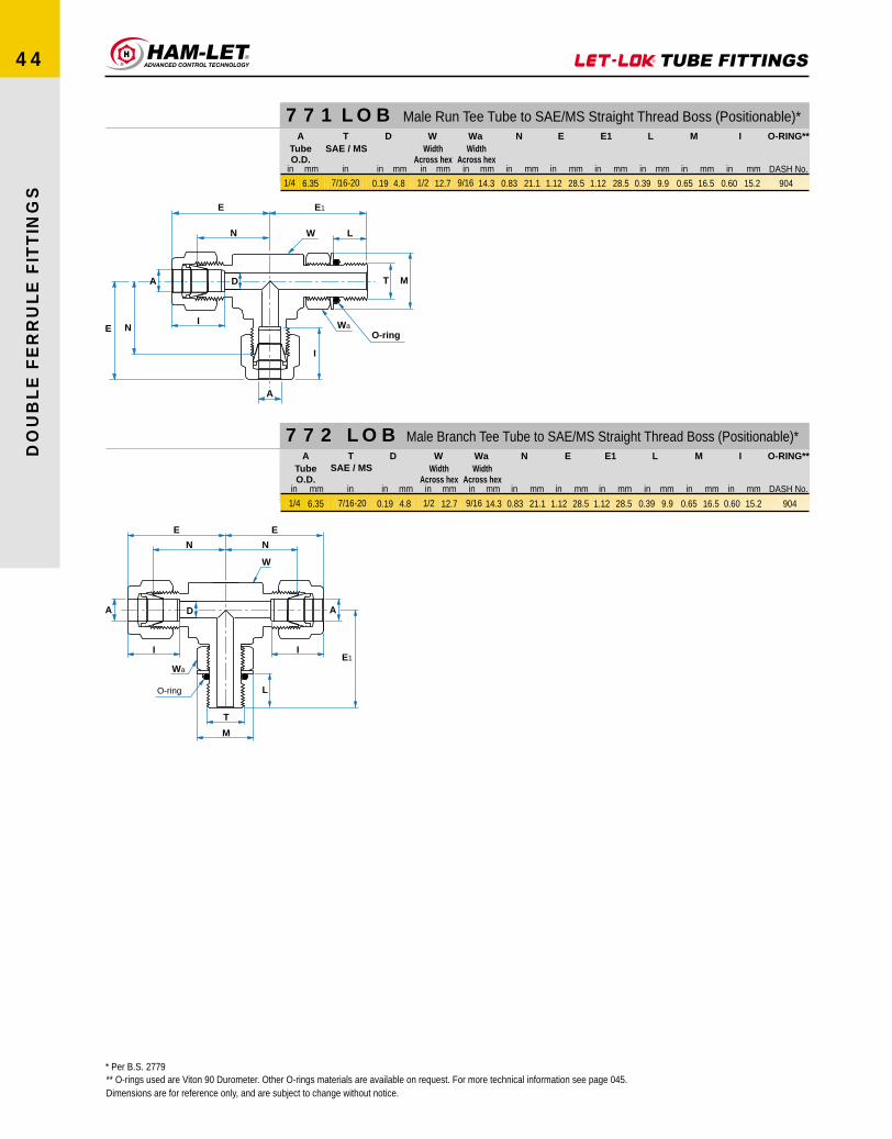
Dimensions are for reference only, and are subject to change without notice.
* Per B.S. 2779** O-rings used are Viton 90 Durometer. Other O-rings materials are available on request. For more technical information see page 045.
DO
UB
LE
FE
RR
UL
E F
ITT
ING
S
44
771 LOB Male Run Tee Tube to SAE/MS Straight Thread Boss (Positionable)*
772 LOB Male Branch Tee Tube to SAE/MS Straight Thread Boss (Positionable)*
E
I
N
D
E Wa
W
E1
T M
L
N
A
I
A
O-ring
E
T
M
O-ring
I
A
N
D
E1
L
Wa
W
N
E
A
I
TubeO.D.
A
1/4 6.35
in mm
TSAE / MS
7/16-20
in
D
4.80.19
in mm
WidthAcross hex
W
12.71/2
in mm
WidthAcross hex
Wa
14.39/16
in mm
N
21.10.83
in mm
E
28.51.12
in mm
E1
28.51.12
in mm
L
9.90.39
in mm
M
16.50.65
in mm
I
15.20.60
in mm DASH No.
O-RING**
904
TubeO.D.
A
1/4 6.35
in mm
T
7/16-20
SAE / MS
in
D
4.80.19
in mm
WidthAcross hex
W
12.71/2
in mm
WidthAcross hex
Wa
14.39/16
in mm
N
21.10.83
in mm
E
28.51.12
in mm
E1
28.51.12
in mm
L
9.90.39
in mm
M
16.50.65
in mm
I
15.20.60
in mm DASH No.
O-RING**
904

DO
UB
LE
FE
RR
UL
E F
ITT
ING
S
45
DIMENSIONS FORSAE J1926 & MS 16142 BOSS
MOUNTING DIMENSIONS FOR O-SEAL CONNECTORS (SAE/MS)
Install the fitting into the S.A.E.straight thread boss, figure 2,untill the metal back-up washecontacts the face of the bossas shown in figure 2.
Position the fitting by turningcounter clockwise up to maximumof one turn (see figure 3).
Holding the pad of the thefitting with a spanner,tighten the locknut andwasher against the faceas shown in figure 4.
Figure 1Locking backed off
Lubricate O-ring by inserting itin the groove adjacent to theface of the metal back-upwasher which is assembled atthe extreme end of the grooveas shown in figure 1.
Figure 2Fitting install hand tight
Figure 3Fittings backed - off foralignment (1 turn maximum)
Figure 4Fitting locknut tight toappropriate torque
L2
RecommendedSpotface diameter
D3 REF
D1 Thread
L4
D5
Theoretical Point
R0.4 MaxL
3 M
ax
Z°
L1
45°±5°
INSTALLATION INSTRUCTIONS:
APitch Dia.
3.2 µmm
3.2 µmm
D2
D4
Gauging
This dimension applieswhen Tap Drill cannotpass through entire boss
0.1 A 0.2 A0.2 A
Applies at D4
0.20.1R
Dimensions are for reference only, and are subject to change without notice.
L4
mmMin Full Thread
10
10
11.5
11.5
12.7
14.3
16.7
19
19
19
L3
mmMax
1.6
1.6
1.6
1.6
1.6
2.4
2.4
2.4
2.4
3.2
L2
mmMin
12
12
14
14
15.5
17.5
20
23
23
23
L1
mm± 0.02
2.1
2.1
2.6
2.6
2.7
2.7
2.7
3.5
3.5
3.5
D5
mm± 0.05
9.15
10.75
12.45
14.05
15.70
20.65
24
29.2
32.4
35.55
D4
mmMin
11
13
15
16
18
22
26
32
35
38
D3Min Diameter
mm
1.6
3.5
4.5
6
7.5
10
12.5
16
18
21
D2Min Diameter
± 0.05
17
19
21
23
25
30
34
41
45
49
DIThread Size
Inch
5/16 - 24 UNF - 2B
3/8 - 24 UNF - 2B
7/16 - 20 UNF - 2B
1/2 - 20 UNF - 2B
9/16 - 18 UNF- 2B
3/4 - 16 UNF -2B
7/8 - 14 UNF - 2B
1-1/16 - 12 UNF - 2B
1-3/16 - 12 UN - 2B
1-5/16 - 12 UN - 2B
Tube O.D.
1/8
3/16
1/4
5/16
3/8
1/2
5/8
3/4
7/8
1
3.18
4.76
6.35
7.94
9.52
12.70
15.88
19.05
22.22
25.40
Inch mm
Z°
mm± 1°
12
12
12
12
12
15
15
15
15
15

DO
UB
LE
FE
RR
UL
E F
ITT
ING
S
46
Parallel ThreadPOSITIONABLE ISO
* Per B.S. 2779** O-rings used are Viton 90 Durometer. Other O-ring materials are available on request. For more technical information see page 48.Dimensions are for reference only, and are subject to change without notice.
769 LG Male Elbow Tube (Inch) to ISO Parallel Thread (Positionable)*
769 LG Male Elbow Tube (Metric) to ISO Parallel Thread (Positionable)*
769 LG 45° Male Elbow Tube (Metric) to ISO Parallel Thread (Positionable)*
769 LG 45° Male Elbow Tube (Inch) to ISO Parallel Thread (Positionable)*
E
T
M
O-ring
I
A
N
D
E1
L
Wa
W
W
Wa
I
A
E
N
O-ring
E1
L
TM
D
TubeO.D.
A
1/4 6.35
T(ISO)
1/8-28 BSPP
D
4.00.16
WidthAcross hex
W
12.71/2
WidthAcross hex
Wa
14.39/16
N
19.60.77
E
26.91.06
E1
26.41.04
L
8.10.32
M
17.30.68
I
15.30.60
DASH No.
O-RING**
I.D
8.0
Washer
17.3x1.1
TubeO.D.
A
6
mm
T(ISO)
1/8-28 BSPP
in
D
4.0
mm
WidthAcross hex
W
12.71/2
in mm
WidthAcross hex
Wa
14.39/16
in mm
N
19.6
mm
E
26.9
mm
E1
26.4
mm
L
8.1
mm
M
17.3
mm
I
15.3
mm DASH No.
O-RING**
I.D
8.0
Washer
17.3x1.1
mm
TubeO.D.
A
1/4 6.35in mm
T(ISO)
1/8-28 BSPPin
WidthAcross hex
W
14.39/16in mm
WidthAcross hex
Wa
14.39/16in mm DASH No.
O-RING**
I.D
8.0
Washer
17.3x1.1mm
TubeO.D.
A
6
mm
T(ISO)
1/8-28 BSPP
in
D
4.0
mm
WidthAcross hex
W
14.39/16
in mm
WidthAcross hex
Wa
14.39/16
in mm
N
17.5
mm
E
24.9
mm
E1
24.0
mm
L
8.1
mm
M
17.3
mm
I
15.3
mm DASH No.
O-RING**
I.D
8.0
Washer
17.3x1.1
mm
D
4.00.16in mm
N
17.50.69in mm
E
24.90.98in mm
E1
24.00.94in mm
L
8.10.32in mm
M
17.30.68in mm
I
15.30.60in mm
in mm in in mm in mm in mm in mm in mm in mm in mm in mm in mm mm

DO
UB
LE
FE
RR
UL
E F
ITT
ING
S
47
771 LG Male Run Tee Tube (Inch) to ISO Parallel Thread (Positionable)*
* Per B.S. 2779** O-rings used are Viton 90 Durometer. Other O-ring materials are available on request. For more technical information see page 48.Dimensions are for reference only, and are subject to change without notice.
771 LG Male Run Tee Tube (Metric) to ISO Parallel Thread (Positionable)*
772 LG Male Branch Tee Tube (Inch) to ISO Parallel Thread (Positionable)*
772 LG Male Branch Tee Tube (Metric) to ISO Parallel Thread (Positionable)*
E
I
N
D
E Wa
W
E1
T M
L
N
A
I
A
O-ring
E
T
M
O-ring
I
A
N
D
E1
L
Wa
W
N
E
A
I
TubeO.D.
A
1/4 6.35
in mm
T(ISO)
1/8-28 BSPP
in
D
4.00.16
in mm
WidthAcross hex
W
15.91/2
in mm
WidthAcross hex
Wa
14.39/16
in mm
N
19.60.77
in mm
E
271.06
in mm
E1
26.41.04
in mm
L
8.10.32
in mm
M
17.30.58
in mm
I
15.30.50
in mm DASH No.
O-RING**
I.D
8.0
Washer
17.3x1.1
mm
TubeO.D.
A
6
mm
T(ISO)
1/8-28 BSPP
in
D
4.0
mm
WidthAcross hex
W
12.71/2
in mm
WidthAcross hex
Wa
14.39/16
in mm
N
19.5
mm
E
27.0
mm
E1
26.4
mm
L
8.1
mm
M
17.3
mm
I
15.3
mm DASH No.
O-RING**
I.D
8.0
Washer
17.3x1.1
mm
TubeO.D.
A
1/4 6.35
in mm
T(ISO)
1/8-28 BSPP
in
D
4.00.15
in mm
WidthAcross hex
W
12.71/2
in mm
WidthAcross hex
Wa
14.39/16
in mm
N
19.60.77
in mm
E
26.91.06
in mm
E1
26.41.04
in mm
L
8.10.32
in mm
M
17.30.68
in mm
I
15.30.60
in mm DASH No.
O-RING**
I.D
8.0
Washer
17.3x1.1
mm
TubeO.D.
A
6
mm
T(ISO)
1/8-28 BSPP
in
D
4.0
mm
WidthAcross hex
W
12.71/2
in mm
WidthAcross hex
Wa
14.39/16
in mm
N
19.6
mm
E
24.0
mm
E1
26.4
mm
L
8.1
mm
M
17.3
mm
I
15.3
mm DASH No.
O-RING**
I.D
8.0
Washer
17.3x1.1
mm

INSTALLATION INSTRUCTIONS
ISO PARALLEL THREAD PER B.S. 2779
Min machine and flat area
B
C
A
T
Min
Use
ful T
hrea
d
Install the fitting into the straightthread boss, figure 2, untill themetal back -up washercontacts the face of the bossas shown in figure 2.
Position the fitting by turningcounter clockwise up to maximumof one turn. see figure 3.
Holding the pad of the thefitting with a wrench,tighten the locknut andwasher against the faceas shown in figure 4.
Figure 1Locking backed off
Lubricate O-ring by installing itin the groove adjacent to theface of the metal back-upwasher which is assembled atthe extreme end of the grooveas shown in figure 1.
Figure 2Fitting install hand tight
Figure 3Fittings backed - off foralignment (1 turn maximum)
Figure 4Fitting locknut tight toappropriate torque
MOUNTING DIMENSIONS CONNECTORST A
Thread Minor DiameterB
Min Machineand Flat Area
1/8 - 28 0.35
Female
Min.Max
Inch mm Inch mm
8.89 0.34 8.64
CMin Useful
Thread
Inch mm Inch mm
0.53 13.50 0.28 7.00
3.2 µmm
DO
UB
LE
FE
RR
UL
E F
ITT
ING
S
48


