
T r u e D o u b l e C o n v e r s i o n
E x c e p t i o n a l R e l i a b i l i t y
U n m a t c h e d P e r f o r m a n c e
B e s t T o t a l S y s t e m V a l u e
H i g h A v a i l a b i l i t y C o n f i g u r a t i o n s :1 + 1 R e d u n d a n t
D i s t r i b u t e d R e d u n d a n t ( D u a l B u s )
Liebert ®
PP oo ww ee rr AA vv aa ii ll aa bb ii ll ii tt yyN p o w e r ™ 30 to 130 kVA
THE NEW LEADER IN THREE-PHASE UPS PRODUCT

2
WE’VE RE-INVENTED THE DOUBLE-CONVERSION UPS
Today’s business processes cannot be interrupted. Businesses are buying and selling around the world, around the clock, every day.
Even 40-hours-per-week operations need the reliability and maintainability of true 24x7 infrastructure during those 40 hours. That’s
why the cornerstone of your infrastructure should be the most reliable and advanced 3-phase UPS in its power range: the Liebert Npower.
Double Conversion for 100% ProtectionThe UPS must support your business processes by
providing clean, reliable uninterrupted power. A true
double-conversion UPS is the only way to guard against
the full spectrum of power disturbances. Anything less
is a compromise.
Single-conversion UPS products (off-line, line-interactive
and some self-proclaimed "online" topologies) cannot
provide complete protection. Common-mode noise and
frequency variations will pass straight through to the
critical load. In addition, single-conversion products are
vulnerable to input faults.
ActiveStar™ Controls for World-ClassPerformance
The Npower has truly spectacular operating performance,
unmatched by any UPS in the industry. The all-digital
ActiveStar controls are DSP-based and feature unique,
patent-pending technology. The Npower makes fast
adjustments to changing loads, including subcycle
pulse-width corrections to keep the output voltage
waveform nearly flawless.
Output voltage distortion (THD) typically measures less
than 2.5%, under worst-case high-crest-factor, non-linear
loads. The Npower is rugged enough to handle load
branch faults, input faults, 100% step loads, PDU startup
inrush and motor-load startup.
Reliability Comes FirstReliability is a Liebert family tradition. All Liebert three-phase UPS products use double-conversion technology and all have
field-proven critical bus Mean Time Before Failure (MTBF) in excess of one million hours.
100% EffectivenessSags
Surges
FrequencyVariations
WaveformDistortions
Common-ModeNoise
SpikesOutages
Input Faults
Output Waveform, 0-100% Step Load
OutputCurrent
OutputVoltage

3
The combination of rugged inverter and
continuous-rated static switch gives the
Npower exceptional overload capability.
By itself, the Npower inverter can supply
up to 200% of rated capacity for 10 cycles
and 150% for a full minute while
maintaining a true sinusoidal waveform
to the load. It can also handle up to 125%
of rated capacity for ten minutes. Even
during bolted faults, the ActiveStar
controls are able to limit inverter output
current to safe levels.
The internal static switch has two
operating modes. For faults or
transformer inrush currents, the
static switch operates in the pulsed-
parallel mode: the inverter remains
connected while the static switch
supplements inverter current with
power from the bypass source.
If the load continues to exceed
the overload rating of the inverter,
the static switch operates in the
continuous-duty mode.
When Npower is used in the 1+1
Redundant configuration, the full
overload capacity of both modules
is available to source fault current or
handle momentary overloads. The
inverters and static bypass switches
work in parallel to support the critical
load. Total power available will be
limited by the rating and settings
of the system output breaker in the
Paralleling Cabinet. This breaker is
typically set for the output rating
of a single Npower module.
10000
1000
100
6000
3000
1100
600
1/2 cycle 10 cycles 1 sec 5 sec
Time
AM
PS10 cycles 5 sec 1 min. 10 min. 100 min.
%Lo
ad
Time
Inverter
Static Switch
225
200
175
150
125
100110 % Load
Rating of the internal static switch in amps
Overload capability of Npower UPS as a percent of nominal rating
Exceptional Overload Performance
The overload curves above tell a remarkable story. The upper curve represents
inverter capability as a function of overload versus time. The inverter remains on-line
providing regulated power output at full voltage at every point of the overload/time
curve. The lower curve represents the capabilities of the internal static switch. If
the load moves beyond the line representing inverter capacity, the static switch
will support the load to the full extent of its capacity.
The static switch has truly exceptional fault-clearing capacity, as shown in the
second chart above. All Npower models have static switches rated for 6000 amps
for the first half cycle, 3000 amps for 10 cycles, 1100 amps for one second and 600
amps for 5 seconds.

4
ACTIVESTAR™ CONTROLS FOR WORLD-CLASS PERFORMANCE
ActiveStar is a DSP-based control system that makes the UPS behave like a model citizen. ActiveStar controls the entire power train,
including the Rectifier, DC Bus, Inverter and Static Switch. This makes the Npower very aware of its environment, and able to make
intelligent adjustments.
Rectifier and DC BusThe rectifier has an unusually large
window of usable input voltage.
Npower is able to operate at full load
without discharging the batteries
even when input voltage drops 20%
below nominal. The feed-forward
frequency control of the rectifier
allows it to track the output of an
unstable generator.
When the rectifier senses a large
load step, it makes sub-cycle
corrections to its phase angle and
immediately begins drawing more
power into the DC bus. This minimizes
the effect of short-duration "hits" on
the battery string and extends
battery life.
At lower load levels, ActiveStar
disconnects the input filter capacitors,
to keep from presenting a leading
power factor to the utility or to
the standby genset. As the load
increases, ActiveStar reconnects
the capacitors, to optimize the
input power factor and minimize
harmonic currents reflected back
to the input source.
Npower takes very good care
of its batteries, with temperature
compensated charging and other
UtilityInput
NpowerRectifier
Input Filter Disconnect
Input Inductor
Trap Inductors
important features. As mentioned
earlier, the rectifier responds quickly
to load steps, reducing the number
of short-duration battery "hits,"
which can greatly reduce battery life
expectancy. In addition, the Npower
can schedule regular battery self-test
procedures, to verify that the battery
string is capable of supporting the
connected load.
The internal battery cycle monitor
records the duration, kW and battery
end voltage for every battery discharge
event. This enables you to evaluate
battery performance and see how
hard your batteries are working in
this application.
The ActiveStar controls also
optimize battery performance
during longer discharge periods.
During longer battery discharge
events, the Npower gradually
increases the low-battery shutdown
voltage. This prevents the batteries
from being discharged too deeply,
and incrementally improves battery
service life.

5
InverterThe ActiveStar inverter controls have three elements,
Voltage Harmonic Control, Sliding Mode Inverter
Current Control, and Space-Vector PWM Inverter.
Voltage Harmonic Control compares the actual UPS
output voltage to a 60Hz reference signal. It senses the
content of load-generated harmonics and components
introduced by unbalanced loads, and computes the
compensating signals necessary to eliminate them.
The Stabilizer then computes the amount of current
necessary to force the voltage error to zero and ensure
system stability.
The Sliding-Mode Current Control takes the output
from the Stabilizer and determines the driving voltage
necessary to make inverter currents follow what the
voltage control desires. The Current Control corrects
errors between desired and actual current in a single
PWM pulse. On a bolted fault, this allows the inverter
to limit its current at a safe level, rather than requiring
immediate shutdown when bypass is not available.
ActiveStar compensates once per PWM pulse (50 times
per line cycle) compared to older UPS technology, which
limits currents by gradually reducing its 60 Hz voltage
reference once per line cycle (1/60 sec.).
ActiveStar constantly monitors the harmonics being
reflected by the customer’s load equipment, and cancels
them electronically. The inverter sources (compensates
for) the harmonics as it sends pulses through the output
isolation transformer. As a result, the output transformer
never directly experiences the harmonics, and runs
cooler and quieter.
ActiveStar Inverter Elements
60HzVoltage
Reference
Voltage Error
Desired InverterCurrents
Current Error
Desired DrivingVoltage
PWMPulses
MeasuredOutputVoltage
MeasuredInverterCurrent
FastAutomaticHarmonic
Voltage Control(See detail below)
Sliding ModeInverterCurrent
Control/Limit
SpaceVectorPWM
Desired InverterCurrents
60HzVoltage
Reference
VoltageError
MeasuredOutputVoltage
Measured SystemOutput Currents
STA
BIL
IZER
FundamentalFrequency
3rdHarmonic
5thHarmonic
7thHarmonic
etc
Details of Fast AutomaticHarmonic Voltage Control

NPOWER: THE BEST VALUE IN A MID-RANGE UPS
The Npower gives you more UPS for about the same initial cost as lesser products. Furthermore, the Npower will usually cost
significantly less over the lifetime of the product.
The value comes from several elements: exceptional protection, higher efficiency, lower installation, maintenance and operating
costs, smaller total system footprint and more standard features.
Higher Efficiency in Real-WorldApplications
Critical applications require a UPS to have an input filter
(to reduce input current distortion) and an output isolation
transformer (to isolate your critical load), while powering
non-linear (high-crest-factor) loads at less than the rated
capacity of the UPS.
The fully equipped Npower has excellent efficiency –
typically between 92% and 93.5% – while powering high-
crest-factor loads between 50 and 100% of its rated capacity.
Furthermore, the input power factor is exceptionally high,
typically 0.95 to 0.96 for models with 480 VAC input.
In this power range (up to 130 kVA), the only way to
exceed 93.5% efficiency is to leave out something important.
Some competitors omit the output isolation transformer;
others put your critical load at risk with their single-conversion
UPS products. Only you can decide if the claimed
savings justify the risk.
High-Availability ConfigurationsThe Npower UPS can be used reliably as a single module
and in various redundant configurations. The Npower 1+1
Redundant option, described on pages 10-11 of this
brochure, is a cost-effective parallel-redundant system.
Parallel redundancy improves maintainability and fault
tolerance, thereby enhancing system availability.
For the ultimate in high-availability systems, Npower
can be applied in various distributed-redundant
(dual-bus) configurations, using Liebert’s unique Load
Bus Sync™ option. Both Load Bus Sync and 1+1 Redundant
configurations can be factory-installed or retrofitted to
existing Npower installations.
6

7
35
30
25
20
15
10
5
0LiebertNpower
Brand M Brand P Brand A
130 k
VA
80 k
VA
50 k
VA
130 k
VA
80 k
VA
50 k
VA
130 k
VA
80 k
VA
50 k
VA
130 k
VA
80 k
VA
50 k
VA
System FootprintUPS+Batt+Output Isolation
The Npower can be as simple or complete as you need it to be.With matching battery cabinets, maintenance bypass cabinets,Slim-Line power distribution cabinets and Paralleling Cabinets,the Npower can be a bolt-together system.
All bolt-on cabinets have casters and leveling feet,
to simplify installation. Furthermore, power cables
and control wiring harnesses between cabinets are
included for all cabinets (except Paralleling Cabinets),
saving time and cost.
Smallest Complete-System FootprintThe Npower achieves a small footprint despite being a
full-featured, double-conversion UPS. Furthermore, Liebertunderstands that real systems have battery cabinets, maintenance bypass cabinets and some type of power distribution cabinets. Therefore, our design goal was tobuild complete systems, in all their variant forms, in thesmallest practical size consistent with good engineeringpractices. Consider this:• No size penalty for 208 VAC input or output. For each
kVA rating, all input voltages and all output voltages fit in the same size package.
•Input isolation and bypass isolation transformers fitinside the same package.
•Battery trays slide out the front for maintenance.• Bypass isolation transformers can also be built into your
maintenance bypass cabinet.• The Slim Line distribution unit adds just 10 inches to the
width of the UPS module, but gives you 42 or 84 poles.
Easy to Purchase and Install
Sys
tem
Foo
tprin
t (S
q. F
t.)

8
NPOWER: CONFIGURATIONS FOR ANY APPLICATION
Input and OutputConfigurations
SSiinnggllee oorr DDuuaall IInnppuutt::
•Single-input UPS products are often
favored in this power range (30 to
130 kVA). This is the simplest and
lowest-cost solution. It features a
single input bus, with both the
input and bypass circuits fed from
the same external feeder breaker.
•Dual-input UPS products have
separate busses for the rectifier input
and the bypass circuit. This adds a
measure of fault tolerance, because
a single external breaker failure will
not cause the load to fail. It also
adds cost: an additional input feeder
breaker and more input cabling.
IIssoollaatteedd oorr NNoonn--IIssoollaatteedd NNeeuuttrraall
Proper grounding is essential for
reliable UPS operation. The installing
contractor must ensure the integrity
of the ground and neutral connections
and select the UPS best suited for
the facility.
The Npower can be ordered with
or without an isolated bypass neutral.
With an isolated neutral, the UPS
contains an internal bypass isolation
transformer and does not require an
One-Line DiagramSingle-Input with delta-wye output
BatteryCabinet
ContinuousRated Static
Switch
Rectifier InverterUPSInput
Critical Load
Y
input neutral brought in from the
service entrance. Shown below are
the various configurations and
their applications:
• A non-isolated neutral is the
lowest-cost option, but requires
the installing contractor to pull a
neutral line from service entrance.
This configuration can support
three-wire or four-wire-plus-
ground loads where the input and
output voltages are the same.
• An isolated neutral with Delta-Wye
isolation transformer is able to
support 3-wire or 4-wire-plus-
ground loads of any sort.The
output is phase-shifted 30 degrees
from the input.
• An isolated neutral with Wye-Wye
isolation transformer is able to
support 3-wire loads at the supply
voltage. The output is in phase
with the input. This configuration
cannot support 4-wire loads.
Sing
le In
put C
onfig
urat
ions
D
ual I
nput
Con
figur
atio
ns
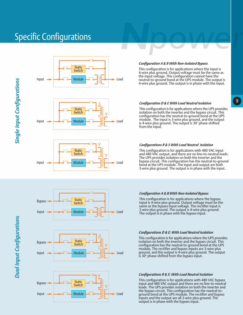
Configuration A & B With Non-Isolated Bypass
This configuration is for applications where the input is 4-wire plus ground. Output voltage must be the same asthe input voltage. This configuration cannot have the neutral-to-ground bond at the UPS module. The output is4-wire plus ground. The output is in phase with the input.
Configuration D & E With Load Neutral Isolation
This configuration is for applications where the UPS providesisolation on both the inverter and the bypass circuit. Thisconfiguration has the neutral-to-ground bond at the UPSmodule. The input is 3-wire plus ground, and the output is 4-wire plus ground. The output is 30° phase-shifted from the input.
Configurations R & S With Load Neutral Isolation
This configuration is for applications with 480 VAC inputand 480 VAC output, and there are no line-to-neutral loads.The UPS provides isolation on both the inverter and thebypass circuit. This configuration has the neutral-to-groundbond at the UPS module. The input and output are both3-wire plus ground. The output is in phase with the input.
Configuration A & B:With Non-Isolated Bypass
This configuration is for applications where the bypassinput is 4-wire plus ground. Output voltage must be thesame as the bypass input voltage. The rectifier input is 3-wire plus ground. The output is 4-wire plus ground. The output is in phase with the bypass input.
Configurations D & E: With Load Neutral Isolation
This configuration is for applications where the UPS providesisolation on both the inverter and the bypass circuit. Thisconfiguration has the neutral-to-ground bond at the UPSmodule. The rectifier and bypass inputs are 3-wire plusground, and the output is 4-wire plus ground. The output is 30° phase-shifted from the bypass input.
Configurations R & S: With Load Neutral Isolation
This configuration is for applications with 480 VAC bypassinput and 480 VAC output and there are no line-to-neutralloads. The UPS provides isolation on both the inverter andthe bypass circuit. This configuration has the neutral-to-ground bond at the UPS module. The rectifier and bypassinputs and the output are all 3-wire plus ground. The output is in phase with the bypass input.
Module
StaticSwitch
Input Load
Module
StaticSwitch
Input Load
Y
Module
StaticSwitch
Input Load
Y
Module
StaticSwitch
Input Load
Module
StaticSwitch
Input Load
Y
Module
StaticSwitch
Input Load
Y
Bypass
Bypass
Y
Y
Bypass
9
Specific Configurations

10
NPOWER 1+1 REDUNDANT:A SIMPLER WAY TO IMPROVE AVAILABILITY
The Npower 1+1 Redundant system is an elegantly simple way to create a parallel-redundant UPS without the cost or complexity of
external system controls. Adding a redundant UPS module to a single-module system improves maintainability, because the second
module can support the load while the first is being serviced. A redundant module also improves fault tolerance, because a single
failure will still leave an intact UPS to support the critical load.
No System-Level ControlsAll control logic is contained within the individual
modules. Unlike conventional multi-module systems,
there is no system-level LCD panel or static bypass switch.
The module-level static bypass switches work in
coordination to provide exceptional overload protection,
plus seamless transfers between bypass and online
operating modes.
Furthermore, the traditional system control cabinet
is replaced by a simple paralleling cabinet. Normal
operations can be handled efficiently at the individual
module control panels.
Module
StaticSwitch
Input
Load
ParallelingCabinet
UPS1
Module
StaticSwitch
Bypass
UPS2
Liebert has nearly 30 years of experience building
multi-module UPS systems, but the majority of these
systems have system-level controls. These controls are
necessary for large-scale power systems, but are less
important for smaller systems. The Npower 1+1
Redundant system strikes a good balance between
the simplicity of a single module and the performance
of a multi-module system.

11
Better than WirelessBoth UPS modules in an Npower 1+1 system are
completely independent. They function as true peers,
rather than as master or slave.
A single Category 5 Ethernet cable connects the
modules. The cable enables the modules to “learn” and
calibrate themselves during initial system start-up. After
start-up, the cable optimizes system communications
and performance in several areas. It enables the modules
to load share with a precision of +/- 1%. It also enables the
modules to load share during battery discharge,
improving battery runtimes by 15-30%.
Although it enhances system performance, the cable
is not required for system operation. Should the cable
become severed or disconnected, the Npower modules
will continue to share load within +/- 5% (typically within
+/- 3%). The system will continue to provide conditioned
power to the critical load without interruption. Likewise,
the modules will still be capable of automatic fault
isolation, and the operator can still perform manual
transfers to and from bypass.
In summary, Liebert system designers chose the
performance advantages of a wired paralleling system,
but the wires were not permitted to become a
failure mode.
New or RetrofitAll configurations of Npower modules can be used in
1+1 Redundant systems. New systems can be ordered
with all the components included. Installed systems
can be retrofitted with a simple kit.
Paralleling Cabinets: Better SolutionsNpower 1+1 Paralleling Cabinets feature three circuit
breakers: two module disconnect breakers and a system
output breaker. The third breaker meets NEC requirements
for a system output breaker. Some competitor products
only have the two module disconnect breakers. This
forces the installing contractor to size, purchase,
coordinate, install and run conduit to an external
output breaker.
Our standard wall-mounted panelboards give great
flexibility in component placement. Consult your Liebert
sales representative for optional cabinet configurations.

OpenComms Nform
OpenComms NformMultiLink
OpenComms Nform
OpenComms NformSiteScan Web
SiteScan WebEnvironmental
Control
Power Management
Single PhaseUninterruptible Power System
Three PhaseUninterruptible Power System
EnterpriseFacilityData CenterNetworkIT Manager
LIEBERT MONITORING SOLUTIONS: WHEN YOU NEED TO KNOW
12
Stand-Alone Monitoring Solutions UPS shutdown software, as well as autonomousmicroprocessor controlled modules, are availableto provide supervision, control and remotealarm notification for Liebert power equipment.
MultiLink™ Automated Shutdown SoftwareMultiLink will monitor UPS status and performuser-specified actions to execute notificationsand provide automated, unattended systemshutdown to protect critical data during extended power outages.
Universal MonitorAll-purpose microprocessor-based alarm and notification unit that allows a variety of Liebertequipment to be monitored and controlled bothremotely and locally from a single point.
Liebert has built advanced monitoring
and communications capabilities into the
Npower UPS system. Liebert monitoring
and control products allow you to take
full advantage of these features. You will
find a full range of monitoring and control
systems, communications modules and
other equipment designed to interface
with a variety of communication
protocols, operating platforms and
building management systems. Knowing
what is happening with your power
equipment, so you can keep it at peak
operating efficiency, is vital to
system reliability.
Important facility operational and status
information needs to be communicated by
different means with varying levels of
importance. This is why Liebert gives you
so many ways to supervise your enterprise:
SiteScan™ Web EnterpriseMonitoring SystemsSiteScan™ Web is a comprehensive critical systems monitoring solution dedicated toensuring reliability through graphics, eventmanagement and data extrapolation. The standard Web interface allows users easy access from “anywhere” at “anytime.” •Single and multi-site applications.•Event management and unit control.•Trend and historical data captures
and reporting.•Full ASHRAE BACnet compatibility.•Java based.•Windows 2000 and XP compatible.
Network-Based Monitoring SystemsThe OpenComms™ Nform family of monitoring software and communications hardware solutions combines the coverage of facilitymonitoring with the efficiency of a network-based system. They provide a cost-effective, centralized monitoring solutionflexible enough to support your critical systemconfigurations while utilizing your existing distributed infrastructure.
SiteScan™ Web EnterpriseMonitoring Systems
Network-Based Monitoring Systems
Stand-Alone Monitoring Solutions

13
Monitoring And Service Solutions From Liebert Global Services
Remote Monitoring Service: When You Need To Know - But Can’t Do It Yourself
The key to providing proper service for critical support
systems is being aware of that equipment’s operating
status at any given time. That’s why Liebert is so firmly
committed to providing monitoring capability in our
power products. Our Remote Monitoring Service is
designed to maximize the capabilities of your Liebert
equipment by maximizing the effectiveness of your
monitoring systems.
Always There, Always AlertCombining the capabilities of your Liebert monitoring
systems with Liebert Global Services’ (LGS) Remote
Monitoring Service provides you with a seamless
rapid-response system. Liebert can monitor your facility
around-the-clock from the LGS Customer Response
Center (CRC).
When a problem is detected, the monitoring system
immediately alerts the CRC where each alarm is evaluated
and processed. The alarm processor offers instant phone
assistance using a customer-defined response and call
escalation plan. Liebert will coordinate all service
vendors, track the response and solution time for service
calls and provide comprehensive reports on alarms
and corrective actions.
No matter where your facilities are located, LGS Remote
Monitoring can provide continuous oversight of a wide
range of critical installations. From simple, single-unit
unmanned electrical shelters to complex campus-based
data centers, LGS Remote Monitoring Service can help
you keep watch over critical protection equipment.
LGS Service ExcellenceOur Service Excellence programs provide a simple and
easy to understand strategy for meeting all of your
company’s service needs. Basic, Essential, and Preferred
service levels allow you to select the complement of
critical power services that best fits your requirements.
These programs include guaranteed four-hour response
time, emergency service and preventive maintenance.
Liebert Global Services provides unequalled coverage
and support with over 300 factory-trained customer
engineers located coast-to-coast. With access to
thousands of parts in the field, and hundreds of factory
parts depots, our customer engineers have direct access
to the most comprehensive authorized parts network in
the industry. This results in immediate parts availability,
or within 24 hours, guaranteed.
Training And Support Make The Difference
Our factory-trained customer engineers receive
in-depth instruction and hands-on experience in servicing
the most current Liebert products. We also provide them
with immediate online access to detailed schematics and
your equipment’s complete service record from the time
it was started up. With access to our national technical
support resources, LGS customer engineers bring the
best training, the best technology and the best network
of technical professionals to your critical space.

14
UPS Rating Battery Maximum Heat Dimensions (WxDxH)2 Approximate Weight3
Nominal Dissipation At
kVA kW (VDC) Full Load (BTU/Hr)1 Inches MM Pounds KG
30 24 480 8,500 31.7x32.5x71 805x825x1800 2,200 1,000
40 32 480 11,000 31.7x32.5x71 805x825x1800 2,200 1,000
50 40 480 14,000 31.7x32.5x71 805x825x1800 2,200 1,000
65 52 480 18,000 39.4x32.5x71 1000x825x1800 2,700 1,225
80 64 480 22,000 39.4x32.5x71 1000x825x1800 2,700 1,225
100 80 480 26,000 49.2x32.5x71 1250x825x1800 3,800 1,725
130 104 480 33,000 49.2x32.5x71 1250x825x1800 3,800 1,725
Matching Battery Packs
Battery Time In Minutes/UPS kVA Dimensions (WxDxH) Weight3
Model 30 40 50 65 80 100 130 Inches Millimeters Lb Kg
1FJ 11 7 25x32.5x71 635x825x1800 1,600 725
1HJ 21 14 10 5 25x32.5x71 635x825x1800 1,800 815
1LJ 28 19 14 8 5 25x32.5x71 635x825x1800 2,350 1,065
1MJ 35 25 18 12 8 5 25x32.5x71 635x825x1800 2,350 1,065
1PJ 54 38 28 20 15 10 25x32.5x71 635x825x1800 3,000 1,360
1PJ 7 49x32.5x71 1000x825x1800 3,350 1,520
1RH 66 46 35 25 19 13 9 49x32.5x71 1000x825x1800 3,900 1,773
1UH 74 52 40 30 22 17 11 49x32.5x71 1000x825x1800 4,250 1,932
1WH 109 77 56 41 33 25 17 49x32.5x71 1000x825x1800 5,450 2,477
2PJ 100 74 50 38 28 2 x 25x32.5x71 (2x) 635x825x1800 6,000 2,720
2PJ 20 2 x 49x32.5x71 (2x) 1000x825x1800 6,700 3,040
2RH 80 61 46 35 26 2 x 49x32.5x71 (2x) 1000x825x1800 7,800 3,545
2UH 94 69 52 39 31 2 x 49x32.5x71 (2x) 1000x825x1800 8,500 3,864
2WH 102 78 61 40 2 x 49x32.5x71 (2x) 1000x825x1800 10,900 4,955
Specifications
1 Heat dissipation figures are for worst-case configurations (including 208 VAC, input and output), supporting 100% load at rated power factor.2 Dimensions and weights do not include battery or maintenance bypass cabinets.3 Weights are for heaviest models, with 208 VAC input.
InputVoltage: 208, 220, 240, 480 or 600 VAC,
60 Hz. 3-phase, 3-or 4-wire plus ground
Voltage Range: +10, -15% (no battery
discharge at -20%)
Frequency Range: 60 Hz, ± 5 Hz
Current Distortion: 10% maximum
reflected THD at full load with optional
input filter. 30% THD without filter.
Current Limit: 115% of full load
input current
Current Walk-in: 20 seconds to full load.
Power Factor: Up to 0.96 lagging at full
load with optional input filter. 0.80
lagging minimum at full load without
optional input filter.
Surge Protection: Sustains input surges
without damage, per criteria listed in ANSI
C62.41-1980, A & B (IEEE 587).
OutputVoltage: 208, 220, 240, 480 or 600 VAC,
60 Hz, 3-phase, 4-wire plus ground.
Voltage Adjustment Range: ±5%.
Voltage Regulation:
±0.5% for balanced load
±1.0% for 100% unbalanced load.
Dynamic Regulation: ± 2.5% deviation
for 100% load step. ±1% for loss or return
of AC input.
Transient Response Time: Recover to
steady state within 1 cycle.
Voltage Distortion: For linear loads,
1% THD. Less than 2.5% THD for 100%
nonlinear loads (3:1 crest factor) without
kVA/kW derating.
Phasing Balance: 120° ±0.5° for balanced
load. 120° ±1° for 100% unbalanced load.
Frequency Regulation: ±0.1%.
Load Power Factor Range: 1.0 to 0.7
lagging without derating.
Overload: 125% of full load for ten
minutes. 150% for one minute with
true sinusoidal waveform.
EnvironmentalOperating Temperature: 0° to 40°C (UPS),
20° to 30°C (battery)
Non-Operating Temperature:
-20°C to 70°C.
Relative Humidity:
0-95% non-condensing
Operating Altitude: Up to 6,600 feet
(2000 meters) without derating.
Acoustical Noise: Less than
65 dBA typical, measured 1 meter
from the unit.
StandardsETL Listed to UL 1778 and UL 924 UPS
standards, and CSA certified.
Meets current requirements for safe
high-performance UPS operation.

Options and Accessories• Matching valve-regulated lead-acid
battery packs
• Matching maintenance bypass cabinet
• Matching bolt-on power distribution
unit, with one or two 42-pole panels
• Input filter/power factor correction
• Internally mounted input
isolation transformer
• Load Bus Sync™ Systems
• 1+1 Redundant Systems
• Flooded rack-mounted
battery systems
• SNMP, SiteScan and other
communications interfaces:
• Remote monitor panel
• Alarm status contacts
• Customer alarm inputs
15
Standard FeaturesLike other Liebert UPS products, the Npower
includes some features that are options
(or not available) for some competitors:
• True double-conversion topology, for
protection against 100% of power
disturbances.
• Internal bypass switch enables you to
isolate the UPS for maintenance.
•Continuous-duty static switch performs
in pulsed-parallel mode for supplying
fault current and momentary overloads,
and can operate continuously for
longer-duration events.
• Internal output isolation transformer
protects your critical load from
common-mode noise and harmful DC
offsets. In some configurations, it
provides a separately derived source,
to support 4-wire loads without having
to pull a neutral line from the
service entrance.
• Automatic input filter disconnect
isolates the input filter capacitors at
light loads to avoid presenting a leading
power factor to the utility or backup
generator.
• Backlit LCD graphic display enables easy
navigation between the graphic mimic
screen and the menu screens.
• Event Log can display up to 512 time-
and-date-stamped alarm events.
• Battery self-test helps verify the
battery’s readiness to carry the
critical load.
General Specifications
• Battery temperature-compensated
charging prevents overcharging in high
ambient operating temperature
or undercharging in cold weather.
• Battery Cycle Monitor records up to 132
battery discharge events.
• Battery Time Remaining feature displays
backup time remaining at present
connected load.
• On-generator battery charge limit
reduces recharge current until the
utility AC power is restored.
• Front-panel control of all configuration
and field-adjustment options simplify
installation and maintenance.
• Top-and-bottom cable entry gives
the installer more options for
equipment location.
• Two-hole bus bar landing space and
accessible terminal blocks for options
can simplify installation.
• Casters under the unit are helpful when
a forklift is not readily available.
• One-button startup for
simpler operation.

L I E B E R T C O R P O R A T I O N
1050 DEARBORN DRIVE
P.O. BOX 29186COLUMBUS, OHIO 43229800.877.9222 PHONE (U.S. & CANADA ONLY)614.888.0246 PHONE (OUTSIDE U.S.)614.841.6022 FAX
VIA LEONARDO DA VINCI 8ZONA INDUSTRIALE TOGNANA
35028 PIOVE DI SACCO (PD)ITALY
39 049 9719 111 PHONE
39 049 5841 257 FAX
23/F ALLIED KAJIMA BLDG.138 GLOUCESTER ROAD
WANCHAI
HONG KONG
852 2 572 2201 PHONE
852 2 831 0114 FAX
L I E B E R T W E B S I T E
http://www.liebert.com
2 4 X 7 T E C H S U P P O R T
1 800 Liebert (543 2378) PHONE
614 841 6400 (OUTSIDE U.S.)
PP oo ww ee rr AA vv aa ii ll aa bb ii ll ii tt yyN p o w e r ™ 30 to 130 kVA
No matter where your needs for protecting the infrastructure ofyour facility are heading — Liebertis the one source that can deliverthe right solution.
The Liebert Experience
No organization in the world today has a better understanding of exactly what it takes to keep critical infor-
mation and industrial processes operating continuously than Liebert.
It starts with your local Liebert Representative, Distributor or Reseller. We are the only compa-
ny in this business that maintains such a strong local presence on a national and international
basis. This resource, coupled with our broad product line, gives Liebert the ability to create a
"tailored solution" that will meet your protection needs precisely and efficiently.
With your purchase of a Liebert product, you are buying into a company that stands behind its
products. You are also aligning yourself with an organization that has a reputation for quality
and reliability that is second to none.
In the systems protection business it's when you need someone to count on that you find out
whether you’ve made the right choice. Liebert customers — many of them with us for over three
decades — already know how good their decision was.
That Is
TOTAL CONFIDENCE IN THE DECISION YOU'VE MADE
While every precaution has been taken to ensure accuracy and completeness in this literature, Liebert Corporation assumes noresponsibility, and disclaims all liability for damages resulting from use of this information or for any errors or omissions.
© 2003 Liebert Corporation. All rights reserved throughout the world. Specifications subject to change without notice.
All names referred to are trademarks or registered trademarks of their respective owners.
® Liebert and the Liebert logo are registered trademarks of the Liebert Corporation.
® Keeping Business in Business is a registered trademark of the Liebert Corporation.
The Emerson logo is a trademark and service mark of Emerson Electric Co.
SL-24529 (R6/03)Printed in USA


