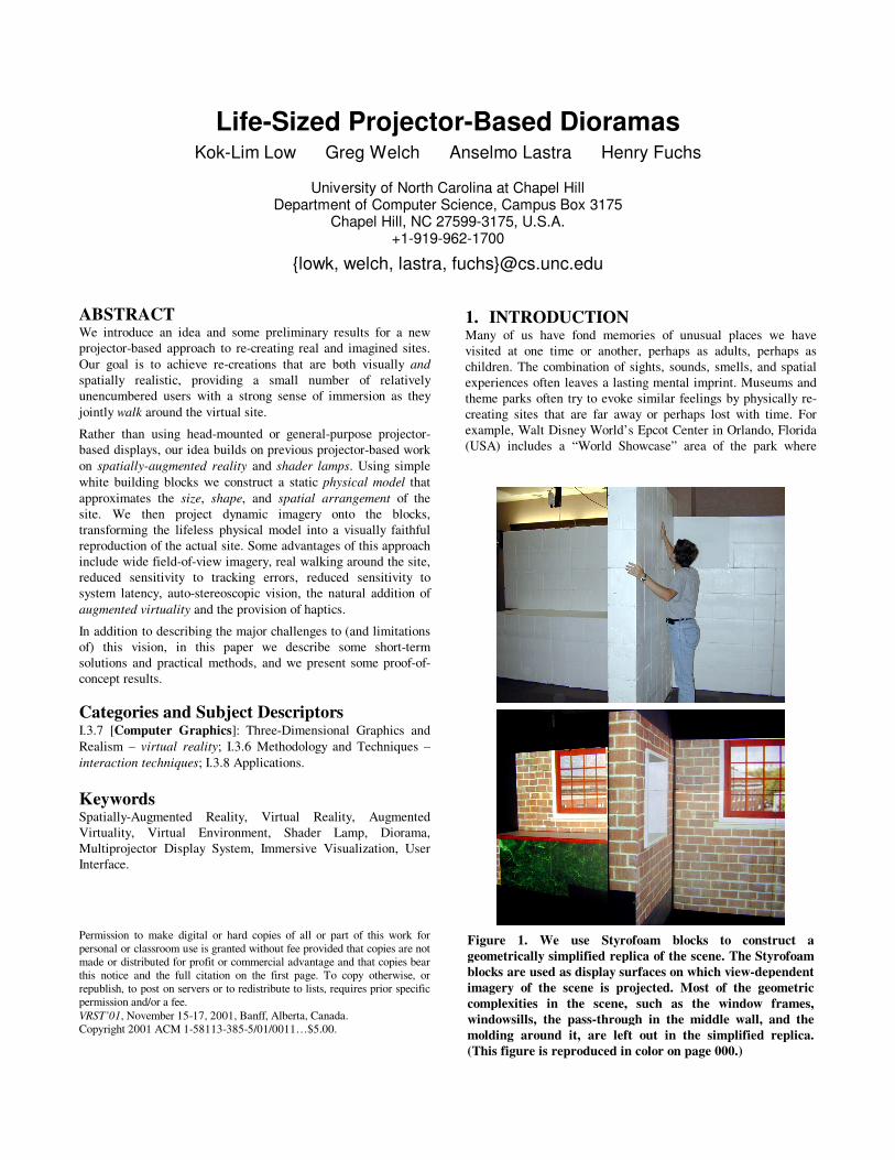
Figure 1. We use Styrofoam blocks to construct a geometrically simplified replica of the scene. The Styrofoam blocks are used as display surfaces on which view-dependent imagery of the scene is projected. Most of the geometric complexities in the scene, such as the window frames, windowsills, the pass-through in the middle wall, and the molding around it, are left out in the simplified replica. (This figure is reproduced in color on page 000.)
Life-Sized Projector-Based Dioramas Kok-Lim Low Greg Welch Anselmo Lastra Henry Fuchs
University of North Carolina at Chapel Hill
Department of Computer Science, Campus Box 3175 Chapel Hill, NC 27599-3175, U.S.A.
+1-919-962-1700
{lowk, welch, lastra, fuchs}@cs.unc.edu
ABSTRACT We introduce an idea and some preliminary results for a new projector-based approach to re-creating real and imagined sites. Our goal is to achieve re-creations that are both visually and spatially realistic, providing a small number of relatively unencumbered users with a strong sense of immersion as they jointly walk around the virtual site.
Rather than using head-mounted or general-purpose projector-based displays, our idea builds on previous projector-based work on spatially-augmented reality and shader lamps. Using simple white building blocks we construct a static physical model that approximates the size, shape, and spatial arrangement of the site. We then project dynamic imagery onto the blocks, transforming the lifeless physical model into a visually faithful reproduction of the actual site. Some advantages of this approach include wide field-of-view imagery, real walking around the site, reduced sensitivity to tracking errors, reduced sensitivity to system latency, auto-stereoscopic vision, the natural addition of augmented virtuality and the provision of haptics.
In addition to describing the major challenges to (and limitations of) this vision, in this paper we describe some short-term solutions and practical methods, and we present some proof-of-concept results.
Categories and Subject Descriptors I.3.7 [Computer Graphics]: Three-Dimensional Graphics and Realism – virtual reality; I.3.6 Methodology and Techniques – interaction techniques; I.3.8 Applications.
Keywords Spatially-Augmented Reality, Virtual Reality, Augmented Virtuality, Virtual Environment, Shader Lamp, Diorama, Multiprojector Display System, Immersive Visualization, User Interface.
1. INTRODUCTION Many of us have fond memories of unusual places we have visited at one time or another, perhaps as adults, perhaps as children. The combination of sights, sounds, smells, and spatial experiences often leaves a lasting mental imprint. Museums and theme parks often try to evoke similar feelings by physically re-creating sites that are far away or perhaps lost with time. For example, Walt Disney World’s Epcot Center in Orlando, Florida (USA) includes a “World Showcase” area of the park where
Permission to make digital or hard copies of all or part of this work for personal or classroom use is granted without fee provided that copies are not made or distributed for profit or commercial advantage and that copies bear this notice and the full citation on the first page. To copy otherwise, or republish, to post on servers or to redistribute to lists, requires prior specific permission and/or a fee. VRST’01, November 15-17, 2001, Banff, Alberta, Canada. Copyright 2001 ACM 1-58113-385-5/01/0011…$5.00.

small�portions�of�cities�from�around�the�world�are�re-created�with�movie�set-like�façades,�and�workers�who�are�natives�of�the�actual�city.� At� the� other� end� of� the� real-virtual� spectrum� are� purely�virtual� examples� such� as� the� London� Traveler� [24],� which�uses�virtual� reality� to� allow� tourists� to� rehearse� a� visit� to� London�before�actually�arriving.�
What�we�seek�is�something�in-between�such�completely�real�and�virtual� examples,� a�spatially�realistic�and�visually�virtual�hybrid�reconstruction.� We� want� to� enjoy� the� richness,� flexibility,� and�dynamic�nature�of� computer�graphics,�while�preserving� some�of�the�physical� and�mental�activity�associated�with�walking�around�or�exploring�a�real�site.�We�want�to�provide�users�with�a�realistic�sense�of�presence�in�both�synthetic�and�real�places.�While�we�are�only�working�in�our�laboratory�at�the�moment,�we�envision�a�day�when� museums� dedicate� a� modest� area� to� life-sized� projector-based� dioramas� of� famous� places� such� as� Monticello†,� U.S.�President�Thomas�Jefferson’s�home�in�Charlottesville,�Virginia.�
1.1� Life-Sized�Projector-Based�Dioramas�Head-mounted� displays� (HMDs)� have� been� commonly� used� for�immersive� visualization� of� virtual� environments.� With� head-tracking,� HMDs� can� provide� real-time� view-dependent� stereo�views�of� the�virtual�world.�Unfortunately,�views�through�HMDs�are�usually�very�narrow,�and�can�detract�from�a�person's�ability�to�navigate� through� an� environment� effectively,� and� decrease� his�sense�of�presence�in�the�virtual�environment�[3].�Further,�HMDs�typically�occlude�most�(or�all)�of�any�peripheral�view�of�the�real�world�and�other�nearby�people,�which�makes�the�user�reluctant�to�move�freely.�
Projector-based� visualization� systems� such� as� the� CAVE™� [6]�surround� the� user� with� large� screens� that� are� fixed� in� the�environment�(not�on�the�user).�The�screens�are� illuminated�with�perspectively-correct�stereo�imagery�from�light�projectors�placed�behind� the� screens.� While� this� approach� improves� the� field� of�view,� it� restricts� the� area� (typically�3�×�3�×�3�cubic�meters)� the�viewer� can� physically� walk� around� when� exploring� virtual�environments.� Placing� the� screens� far� away� to� enclose� enough�walking� space� may� not� be� a� good� solution� for� various� reasons.�For�example,�when�the�viewer�is�at�the�center�of�a�CAVE�looking�at� a� mid-sized� virtual� object� very� near� to� him,� the� far-away�screens�have�to�be�very�tall�in�order�to�allow�the�projection�of�the�complete�image�of�the�object.�
In� this� paper,� we� introduce� a� new� projector-based� approach� for�re-constructions� of� real� and� synthetic� sites.� Our� approach� was�inspired� by� Michael� Naimark’s� “Displacements”� exhibit� at� the�San� Francisco� Museum� of� Modern� Art� in� 1984� [18].� Naimark�used�a�rotating�movie�camera�to�film�a�static�living�room,�replete�with� furniture� and� (still)� people.� The� room� and� furniture� were�then�painted�white,�and�the�captured�imagery�was�projected�back�onto� the� walls� using� a� rotating� projector� that� was� precisely�registered�with�the�original�camera.�
We� introduce� an� interactive� paradigm� that� extends� and�generalizes�Naimark’s�ideas.�Using�simple�white�building�blocks�we�construct� a� static�physical�model� that�approximates� the�size,�shape,� and� spatial� arrangement�of� a� remote� (synthetic)� site.�We��������������������������������������������������������������†�http://www.monticello.org�
then� project� dynamic� imagery� onto� the�blocks,� transforming� the�lifeless�physical�model�into�a�visually-faithful�reproduction�of�the�actual� site.�Besides� increasing� the� spatial� realism�of� the�virtual�environment,� our� approach� has� many� other� advantages� over� the�application� of� traditional� head-mounted� or� CAVE™-like�displays.�
We� have� conducted� some� preliminary� experiments� using� a�synthetic� scene,� and� the� results� are� encouraging.� While� we� are�making�progress� toward�our�goal� to�re-create�real�places,�we�do�not�yet�have�a� complete� system.�As� such,� throughout� the�paper,�we�present�a�mix�of�demonstrated�results�from�new�methods,�and�plausible� ideas�for�future�systems.�We�do�our�best�to�distinguish�between� the� two� lest� the� reader� be� led� to� believe� that�we�have�implemented�something�that�we�have�not.�
In� the� following� section,� we� present� the� basic� idea� behind� our�approach,� and� we� discuss� its� advantages� and� limitations.� In�Section�3,�we�look�at�the�issues�of�implementing�a�system�based�on� our� new� approach,� and� the� challenges� we� face.� Then,� we�demonstrate� some� results� from� our� preliminary� experiments�before�we�conclude�the�paper.�
2.� NEW�APPROACH�Of�course,�one�way�to�realistically�re-create�a�place�is�to�actually�build� an� exact� replica� of� it,� complete� with� all� surface� details,�colors� and� reflectance/photometric� properties.� Except� for�permanent� dedicated� sites� (e.g.,� Disney’s� “World� Showcase”)�this� is� typically� impractical.� Even� if� practical,� the� result� will�generally�be�a�static�model�of�the�site.��
Instead� our� approach� was� closely� based� on� the� idea� of� shader�lamps�[19],�which�extends�and�generalizes�Naimark’s�ideas.�The�concept� of� shader� lamps� is� based� on� the� observation� that� when�we� illuminate� a� physical� object� with� a� white� light,� its� surface�reflects�particular�wavelengths�of�light�that�we�perceive�as�color.�Alternatively,� certain� physical� attributes� can� be� effectively�incorporated� into� the� light� source� to� achieve� a� perceptually�equivalent� effect� using� colored� light� on� a� white� object.� With�shader� lamps�only� the�geometric� structure�of� the�scene�needs�to�be� replicated,� while� digital� light� projectors� fill� in� the� surface�details� and� colors.� Still,� the� geometric� structures� of� real� places�are�usually�complex�and�creating�exact�geometric�replica�can�be�a� daunting� task.� Instead� our� approach� is� to� use� a� geometrically�simplified� replica� of� the� scene� as� the� projection� surface.� The�simplified� surface� is� easier� to� plan� and� build.� In� addition� to�filling� in� surface� details� and� colors,� we� use� the� projectors� to�render�view-dependent� imagery�where�needed�to�compensate�for�the� geometric� differences� between� the� virtual� scene� and� the�simplified�physical�model�(display�surface).�
We�believe�the�extension�of�shader� lamps�is�appropriate�for�our�goal.� For� example,� primary� structures� of� building� interiors� and�mid-sized� architectural� objects� (walls,� columns,� cupboards,�tables,� etc.),� can� usually� be� approximated� with� simple�components�(boxes,�cylinders,�etc.).�As�seen�in�Figure�1,�we�are�using� construction-grade� Styrofoam� blocks� (from� Reddi-Form,�Inc.�[23])� in�our�preliminary�experiment.�The�main�architectural�features�that�match�the�simplified�physical�model�retain�3D�auto-stereoscopic�views,�while�any�other�(more�subtle)�details�must�be�presented�by�projecting�view-dependent�images.�

In� general,� different� degrees� of� approximation� of� the� scene�geometry�produce�a�spectrum�of�display�surfaces�that�range�from�single� flat� screens� (a� CAVE™)� to� display� surfaces� that� exactly�match�the�scene�geometry.�For�our�goal,�we�want�to�simplify�the�display�surfaces�as�much�as�possible�but�still�preserve�the�empty�space� where� the� user� may� walk,� bend� over,� or� put� his� arm�through,� for� instance.�However,� in�Section�2.1,�we�will�see� that�there� are� many� advantages� to� having� the� display� surfaces� as�similar�as�possible�to�the�scene�geometry.�
2.1� Advantages�Although�the�initial�motivation�is�to�provide�more�spatial�realism�to�the�user,�our�approach�has�many�other�advantages�that�are�also�essential� for� achieving�our�goal�of�re-creating�real�places.�Some�of�these�advantages�are�listed�below.�
2.1.1� Wide�FOV�and�Peripheral�Vision�Human� vision� has� an� effective� field� of� view� (FOV)� that� spans�approximately� 200� degrees� horizontally� by� 150� degrees�vertically.� Many� commercially� available� HMDs� have� relatively�narrow� fields� of� view,� ranging� from� roughly� 30� to� 70� degrees�diagonally.� A� narrow� FOV� has� been� shown� (in� real�environments)� to� degrade� human� performance� on� navigation,�manipulation,� spatial� awareness,� and�visual�search�tasks,�and�to�disrupt� our� eye-� and� head-movement� coordination� and� our�perception�of�size�and�space�[8][2][3].�Peripheral�vision�is�known�to� be� well-suited� to� maintaining� self-orientation� during�locomotion� [14],� and� there� is� evidence� to� suggest� that� a�narrow�field�of�view�detracts�from�a�person's�ability�to�navigate�through�an�environment� effectively,� and�decreases�his� sense�of�presence�in�the�virtual�environment.�
One� of� the� main� motivations� of� the� CAVE� system� and� our�approach�is�to�provide�visualization�with�a�very�wide�FOV.�This�is� done� by� using� large� projection� screens� that� are� fixed� in� the�environment�at�some�distance�from�the�user.�Doing�this�also�has�other�advantages�over�HMDs—the�user�no�longer�needs�to�wear�heavy�gear�on�his�head,�and�fast�head�rotations�are�less�likely�to�produce�serious�swimming�effects�[6].�
2.1.2� Real�Walking�With� our� approach,� the� physical� arrangement� of� the� display�surfaces� allows� the� user� to� really� walk� around� in� the� virtual�environment.�Real�walking�gives�stronger�sense�of�presence�than�walking-in-place� and� virtual� flying� [27],� but� at� the� expense� of�larger�physical�space.�
With� systems� such� as� CAVE,� the� virtual� environment� that� the�user� explores� can�be� larger� than� the�enclosed�physical�space.�In�such� a� situation� however,� users� can� only� navigate� using� less�natural� methods� such� as� walking-in-place� or� pressed-button�virtual�flying.�
2.1.3� Reduced�Sensitivity�to�Tracking�Error�Like� general-purpose� projector-based� setups� such� as� the�CAVE™,�where� the�display� surface� is�fixed�in� the�environment�rather�than�to�the�user�(as�in�a�HMD),�our�approach�is�relatively�insensitive� to� error� in�estimates�of� the�head�orientation.�See�[6]�for� a� complete� explanation.� However� unlike� general-purpose�
projector-based� systems,� our� approach� is� also� relatively�insensitive�to�error�in�estimates�of�the�head�position.�
The� diagram� in� Figure�2� illustrates� the� geometry� of� a� general�projector-based� setup� from� a� top� view.� This� will� be� used� to�illustrate�error�in�a�horizontal�plane.�The�vertical�error�would�be�similarly� derived.� The� point� V� represents� some� point� on� the�graphics�model,� i.e.�a�point�on�the�virtual�surface.�If� the� tracker�reports� the�viewpoint� is� at�E1,� the� subsequently� rendered� image�of�point�V�will�appear�on�the�physical�display�surface�at�point�D1.�However�if�the�eye�point�is�actually�located�at�point�E2,�then�the�image� of� point� V� should� have� been� rendered� on� the� display�surface� at� point� D2.� As� a� result,� the� user� will� experience� an�angular�viewing�error�of�θE.��
Note� that� the� shape�of� the�display� surface�is� irrelevant;�because�the� point� D2� is� not� being� rendered,� it� does� not� matter� where� it�should� appear� (anywhere� on� the� line� VE2),� the� user� will� still�experience�the�same�error,�θE.�Similarly� the�absolute�position�of�the�eye�point�is�not�the�critical�factor,�what�matters�is�the�relative�position�of�the�actual�eye�point�with�respect�to�the�rendered�point�D1.�
In� fact,� the� angular� error� θE� depends� only� on� three� parameters:�VE2,� the� distance� from� the� virtual� scene�point� to� the�user’ s� eye�point;� VD1,� the� distance� from� the� virtual� scene� point� to� the�physical�display�surface;�and�θV,�the�angle�between�the�estimated�and� actual� eye� points.� Given� those� three� parameters� and� some�trigonometric�manipulation,� the�angular�viewing�error�θE�can�be�computed�as�
( ) ���
�
�
���
�
�
++=
V
VE
VEVDVEVD
VD
θ
θθ
cos2
)sin(asin
212
22
1
1 �
The� two� surface�plots� in�Figure�3� illustrate� the� angular�viewing�error�θE�throughout�a�space�approximately�the�size�of�a�CAVE™,�for�display� surface�distances�VD1� from�a�virtual�point� at� the�far�corner�of�the�plot�(0,�0)�of�10�and�50�cm.�To�cover�the�space,�θV�is�varied�from�0�to�approximately�90�degrees,�and�VE2� is�varied�between�0�and�2�meters.�
Note�from�the�above�equation�and�plots�that�the�angular�error�(a)�increases� as� the� angle�θV� between� the� estimated�and�actual� eye�points� increases,� (b)� decreases� as� the� distance� VE2� from� the�virtual� scene� point� to� the� actual� view� point� increases,� and� (c)�
virtual�surface�
display�surface�D1�D2�
E1�E2�
θV�
θE�
V�
Figure�2��

�
�Figure�3�
increases� as� the� distance� VD1� between� the� real� and� virtual�surface� increases.�The� first� and� second�cases� are� likely�familiar�to�most�people�who�have�experience�with�conventional�computer�graphics�and�perspective�projection.�However�the�last�case�is�less�frequently� recognized� or� discussed� in� conventional� computer�graphics,�most� likely�because�the�display�surface�and�the�virtual�objects�are�typically�very�different.�The�important�thing�to�note�is�that� even� if� the� display� surface� is� not� precisely� located� and�shaped�like�the�corresponding�virtual�portion�of�the�scene,�if�it�is�relatively� close,� and� if� the� viewer� does� not� get� too� close� to� the�display�surface,�the�angular�error�can�be�relatively�small.�
Note� that� if�VD1�=�0,� i.e.� if� the�physical�display� surface�exactly�matches�the�corresponding�virtual�objects,�then�the�angular�error�θE� is�0�no�matter�what�the�values�of�VE2�and�θV.�In�other�words,�in�that�special�case�you�would�not�even�need�a�tracking�system—you� would� simply� “ paint” � the� display� surface� with� the� proper�colors.�
2.1.4� Reduced�Sensitivity�to�Latency�The� sensitivity� to� view� position� error� with� HMDs� and� general-purpose� projector-based� displays� magnifies� the� effect� of�unavoidable� latencies� in� the� graphics� pipeline.� The� problem� is�that�the�scene�ends�up�being�rendered�from�the�wrong�viewpoint:�from�where�the�user�was,� rather� than�where�he�actually�is.�Such�
latency-induced� viewing� errors� can� break� a� user’ s� sense� of�presence�or�immersion,�and�can�even�cause�motion�sickness.�
In� contrast,� because� our� scene-specific� approach�enjoys� reduced�sensitivity� to� tracker� error,� it� consequently� also� enjoys� reduced�sensitivity� to� system� latencies.� People� typically� translate� their�heads�relatively�slowly,�and�even�fast�head�rotations�cause�only�a�relatively�small�change�in�the�eye�positions.�
The� effect� of� reduced� sensitivity� to� latency� can� be� readily�observed� in� our� prototype� system,� where� system� latencies� are�quite� noticeable� for� the� outdoor� views� through� the� window�(where� VD1� is� quite� large),� but� are� much� less�noticeable� at� the�windowsills� and� the� molding� around� the� pass-through� (where�VD1�is�relatively�small).�
2.1.5� Natural�Auto-Stereoscopic�Vision�When� the� geometry� of� the� display� surfaces� matches� that� of� the�virtual� environment� exactly,� the� images� of� the� scene� projected�onto� the� display� surfaces� are�naturally�3D�stereoscopic,�without�the�use�of�any�special�3D�stereo�projection.�After�all,�the�user�is�viewing�the�actual�3D�surfaces.�When�the�set�of�display�surfaces�is� a� simplified� model� of� the� scene,� only� parts� of� the� scene� that�match� the� display� surfaces� will� retain� auto-stereoscopic� views,�and� other� parts� must� be� reproduced� using� special� 3D� stereo�projection.� In� our� preliminary� experiment,� we� have� many� large�walls� in� the� scene� that� match� the� simplified� display� surfaces.�Even�without� the�use�of� stereo�projection,� the�virtual�scene�still�looks� three-dimensional� because� most� of� the� surfaces� are� very�close�to�the�actual�desired�geometry.�
2.1.6� High�Spatial�and�Geometric�Fidelity�In� traditional� graphics� rendering,� spatial� and� geometric�properties�of� an�object� are�presented�in� images.�The�resolutions�of� these�images�can�limit�the�accuracy�with�which�the�geometric�properties� are�presented.�However,� using�our� approach,�parts�of�the�scene�model�that�match�the�display�surfaces’ �geometry�can�be�presented� with� very� high� spatial� and� geometric� fidelity� [19]—after� all,� aside� from� color,� the� user� is� viewing� a� real� physical�object.�
2.1.7� Eye�Accommodation�As�mentioned�by�Cruz-Neira�[6],�eye�accommodation�(eye�focus)�provides� depth� cues� in� the� real� world.� In� typical� computer�graphics,�HMD�VR�and�CAVE,�eye�accommodation�has�not�been�incorporated� in� visualization,� and� everything� in� the� virtual�environments�is�in�focus.�With�our�approach�and�the�approach�of�the�shader� lamps,� the�user�can�now�selectively�focus�his�eyes�on�any�part�of�the�scene,�thus�providing�the�user�a�very�natural�way�to�visualize�the�virtual�environment.�
2.1.8� Augmented�Virtuality�Because� the� physical� arrangement� of� the� display� surfaces� is�spatially� similar� to� that� geometry� of� the� scene,� it� is� relatively�easy�to�add�real�objects�to�the�virtual�environment.�For�example,�if�a�set�of�display�surfaces�approximates�a�virtual�desk,� then�we�can� put� a� vase� on� the�desk�by�placing�a� real�vase�on� the� set�of�display� surfaces� that� approximates� the� desk.� Additional�projectors� can� then� be� used� to� properly� light� up� the� added� real�object� to� simulate� the� effect� of� the� virtual� lights� in� the� virtual�environments.�

2.1.9� Haptics�Clearly,� if� the� set�of�display� surfaces� is� sufficiently� close� to� the�scene� surfaces,� we� can� use� it� to� provide� the� user� what� Fred�Brooks�has�called�static�haptics�[5][13].�In�an�experiment�setup,�Brooks� et� al.� have� used� low-fidelity,� low-cost� and� easily�configurable� physical� structures� to� construct� very� approximate�physical�model�for�a�kitchen.�The�user�wears�a�HMD�and�moves�in� the�physical�model,�able� to� touch�it�physically,�and�also�see�a�very�detailed�image�of� the�kitchen.�The�effect�of�actually�feeling�the�surfaces�is�a�very�powerful�component�in�achieving�a�sense�of�presence.�Their�experience�has�been�that� the�user’ s�visual�sense�overrides� small� errors� in� the�positioning�and�lack�of�fine�details�of�the�physical�model.�
2.2� Drawbacks�and�Limitations�Probably�the�most�significant�limitation�of�our�idea�is�the�scene-specific�nature�of�the�implementation.�Clearly�the�approach�is�not�applicable� for� general-purpose� visualization,� where� a� CAVE™-like�display�or�a�HMD�is�likely�to�make�more�sense.�As�indicated�by�the�title,�the�idea�is�primarily�useful�(we�believe)�for�creating�life-sized�projector-based�dioramas�of�real�or�imagined�sites.�
2.2.1� Physical�Aspects�Given� a� decision� to� use� our� approach� to� re-create� a� particular�site,� clearly� the� next� most� significant� concerns� are� the�physical�aspects�related�to� the�need�for�a�physical�display�surface�model,�and� for� the� physical� space� to� house� projectors,� cameras,� and�of�course�the�physical�model.�We�believe�that�the�requirement�for�a�physical�model�is�more�onerous�now�than�it�will�be�in�the�future.�As�described�in�Section�3.3�we�have�some�tools�to�help�us�now,�and� we� envision� more� powerful� computer-aided-assembly� tools�in� the� future.� With� respect� to� the� physical� space� requirements,�we� are� now� working� in� a� research� laboratory� so� we� cannot�simulate� a� place� larger� than� it.� However,� we� envision� a�warehouse-sized�structure�in�which�we�can�re-create�most�indoor�scenes.� It� is� also� useful� to� note� that� we� do� not� always� need� to�allocate�physical�space�for�everything�in�the�scene— we�only�need�to� allocate� physical� space� for� those� parts� of� the� scene� that� we�want�the�user�to�move�into.�For�example,�in�Figure�1,�no�physical�space� is� allocated� for� the� outdoor� scene� seen� through� the�windows.�
2.2.2� Scene�Content�We�enjoy�most�of� the�advantages�outlined�in�Section�2.1�only�if�we�keep�the�physical�surfaces�similar�to�the�scene�surfaces.�This�means� that�dynamic� scenes�with� large�objects� that�move�a�great�deal� or� deform� significantly� are� not� good� candidates� for� our�approach.�However,� small�objects� that�move�near� large�surfaces�(for�example,�an�insect�crawling�on�a�wall)�should�not�pose�much�difficulty� to� our� approach.� Moreover,� of� relevance� to� our� goal,�most� museums� exhibit� static� artifacts,� which� visitors� are� not�allowed�to�touch.�
2.2.3� Projector�Considerations�In�general,�our�approach�does�not�always�allow�back-projection�to�be� possible.� For� example,� in�Figure�1,�both� sides�of� the�middle�wall� are� to� be� illuminated� and� there� is� virtually� no� space� in�between�them�to�put� in�projectors.�Although�the�back-projection�approach� has� a� higher� space� requirement,� it� has� the� advantage�
that� users� will� not� occlude� light� from� projectors.� Instead� we�envision�a� “ sea�of�projectors” �arranged�throughout�the�ceiling�of�the� reconstruction� space.� While� it� might� be� an� issue� now,� we�believe� that� projector� size� and� cost� will� not� be� a� significant�consideration�in� the�future.�As�noted�in�[28]�the�size�and�cost�of�projectors� continues� to�decrease� at� a� rapid�pace.�Today�you�can�purchase� a� projector� that� weighs� less� than� five� pounds,� has�1,000+� lumens� of� brightness,� for� under�$5,000.�New,� reflective�micro� displays� based� on� standard� CMOS� technology� offer� the�hope�of�smaller,�smarter,�and�less�expensive�digital�projectors.�
3.� IMPLEMENTATION�We� have� implemented� a� very� preliminary� prototype� to�demonstrate� the� idea� of� our� new� approach,� but� we� do� not� yet�have� a� complete� system.� As� such,� here,� we� do� our� best� to�distinguish� between� what� we� have� implemented� and� what� we�have�not.�
3.1� Overview�A� system� based� on� the� new� approach� will� have� the� following�main�components:�
• Scene�modeling.�The� scene�model�can�be�synthetic�or�of�a�real�place.�
• Display�surface�modeling.�A�model�of�the�display�surfaces�must�be�computed�to�fit�the�surfaces�in�the�scene�model.�
• Physical� display� surface� construction.� A� physical� setup�has�to�be�constructed�in�accordance�to�the�computed�display�surface�model.�
• Projector� placement� and� calibration.� The� projectors� are�placed�at�the�appropriate�places�with�respect�to�the�physical�model,� and� are� then� calibrated� to� find� their� geometric�relations�with�the�physical�model.�
• Tracking.� Each� user’ s� head� must� be� tracked� in� order� to�generate�perspectively-correct�images.�
• Rendering.� This� is� responsible� for� generating� correct�imagery� on� the� display� surfaces� as� viewed� from� the�user’ s�position.� It� must� also� take� care� of� the� overlapping�projections� from� different� projectors,� and� produce� images�that�blend�seamlessly�at�the�overlap�regions.�
Each� of� these� components� is� discussed� in� greater� detail� in� the�following� subsections,� in�which�we�present� the�main�issues,� the�challenges,� our� solutions� and/or� other� possible� ways� to� address�the�challenges.��
3.2� Scene�Modeling�The� main� challenge� here� is� when� we� want� to� re-create� real�places.� To� model� a� real� place,� we� can� use� a� range� scanner� to�sample� the� geometry� of� the� scene,� and� a� camera� to� sample� the�photometric� properties� of� the� scene.� Some� of� the� issues�encountered�are�the�management�of�the�enormous�amount�of�data�acquired,�the�registration�of�the�photographs�with�the�range�data,�and� the� registration� of� the� range� data� from� different� views�[15][17].�If�view-dependent�surface�reflection�is�to�be�simulated,�then�many�more�photographs�of� the�real�scene�have�to�be�taken,�

and� a� light-field� approach� can� be� used� to� render� the� view-dependent�images�[29].�
Currently,� the� most� practical� interactive� rendering� method� for�VR� is� still� the� traditional� polygon-based� z-buffer� approach.�Therefore,� surface� reconstruction� from� range� data� to� generate� a�polygonal� model� [7]� is� necessary.� Mesh� simplification� [11]� is�then� applied� to� reduce� the� number� of� polygons� by� eliminating�redundant�geometric�information.�During�rendering,�photographs�of�the�real�scene�can�then�be�textured�onto�the�simplified�mesh.�
While�we�currently�only�demonstrate�our� ideas�with� a� synthetic�scene,�we�have�collected�and�are�in�the�process�of�preparing�very�high-quality� image-based� models� of� the� Monticello� library.� We�acquired� the�models�using�a�3rdTech� [1]� laser� scanner�during�a�multi-day� trip� to� Monticello� with� our� UVA� collaborator� David�Luebke.�
3.3� Display�Surface�Modeling�and�Construction�The�need�to�model�and�build�non-trivial�physical�display�surfaces�is�a�challenge�not�seen�in�other�projector-based�approaches.�One�of�our�main�objectives�is�that�the�physical�display�surfaces�should�be�easy�to�setup.�This�has� led�us� to�consider�Lego™-like�blocks�from�a�set�of�predefined�simple�shapes.�An�open�question�is�what�is�the�best�general�set�of�predefined�shapes?�
With�a�selected�set�of�predefined�shapes,�we�would�like�to�have�a�method�to�automatically�compute�an�arrangement�of�the�blocks�to�best� fit� the� surfaces�of� the� scene�model.�This� is� a�very�difficult�problem,� and� we� do� not� see� any� similar� problems� in� the�literature.�
In� our� prototype,� we� use� 0.25� � 1.2� � 0.3� cubic� meters� white�stackable� Styrofoam� blocks� to� set� up� the� physical� display�surfaces.�To�create�a�display�surface�model� in� the�computer,�we�have� implemented�a�program�to�allow�us� to�manually�design�an�arrangement�of� the�blocks� to� fit� the�scene�model.�This�model� is�then�used�as�the�blueprint�to�roughly�construct�the�physical�setup.�Later� when� the� projectors� are� calibrated,� we� project� wireframe�images�of� the�display� surface�model�onto� the�physical�blocks�to�help�us�fine-tune�and�correct�the�physical�setup.�
In� the�future�we�envision�using�the�projectors�and�the�analytical�models� of� the� display� surface� to�guide�users� in� the� assembly�of�the� physical� model.� Given� an� empty� space� with� calibrated�projectors,� an� automated� program� could� render� the� outline� of� a�block� on� the� floor,� waiting� for� the� assembly� worker� to� confirm�placement� of� the� block.� Similar� steps� are� applied� to� the�remaining�blocks,�including�stacked�blocks.�
3.4� Projector�Placement�and�Calibration�3.4.1� Projector�Placement�After� the� display-surface� model� has� been� created,� we� need� to�decide�where�we�want�to�place�the�projectors.�We�may�also�want�to� know� the�minimum�number�we�need� to� cover� all� the�display�surfaces.�This�problem�is�similar�to�that�of�the�camera�placement�in�image-based�modeling�[9][25],�but�it�is�made�more�difficult�by�the�fact�that,�besides�their�positions,�we�also�want�to�compute�the�projectors’ �orientations.�
A� method� to� compute� a� good� set� of� projectors’ � positions� and�orientations�would�want�to�take�into�consideration�the�following:�
• physical� and� environmental� constraints� on� the� projector�mounting,�
• maximizing�the�area�of�coverage�of�each�projector,�
• minimizing�overlap�area,�
• maintaining�a�certain�image�resolution�on�display�surfaces,�
• minimizing�possible�occlusion�by�the�user,�
• minimizing�inter-reflections�among�display�surfaces,�and�
• minimizing�the�number�of�projectors.�
In�order� to�minimize�inter-reflections�of� light,� it� is�best� to�avoid�projecting�light�on�a�large�surface�at�a�very�oblique�angle.�
We� have� not� yet� automated� the� projector� placement.�This� is� an�open�area�of�research.�Currently�we�mount� the�projectors�(using�flexible� brackets)� in� places� that� we� believe� accommodate� the�above� considerations,� then� typically� try� a� few� variations� before�settling�on�the�final�pose.�
3.4.2� Projector�Calibration�After� the� projectors� are� positioned� and� oriented� appropriately�with� respect� to� the� physical� display� surfaces,� we� adjust� their�focusing� distances� to�get� the�best� focus�on� the�display� surfaces.�The�next�step�is�to�calibrate�the�projectors�to�find�their�geometric�relations�with�the�scene�model�and�the�display�surface�model.�
To� calibrate� a� projector,� we� need� to� find� a� set� of� pair-correspondences.� Each� pair-correspondence� consists� of� the�coordinates� of� a� 3D� point� in� space,� and� its� corresponding�pixel�coordinates�on�the�projector’ s� image�plane.�With�sufficient�pair-correspondences� (at� least� six,� and� no� four� 3D� points� are�coplanar),�we�can�solve�for�the�projection�parameters�using�linear�least-square�methods�or�nonlinear�optimization�approaches�[10].�To�find�a�pair�correspondence,�we�project�a�known�2D�point�from�the�projector,�which�emerges� from� the�projector� as� a� ray.�Then,�we� move� a� small�display� surface� to� intersect� the� ray,� and�use� a�tracker� to�measure�the�3D�position�of�the�intersection.�These�3D�points� are� then� transformed� from� the� tracker� coordinate� system�into� the� coordinate� system� of� the� scene� model,� using� a� known�transformation.�This�set�of�pair-correspondences�is�used�to�solve�for� the� projector’ s� projection� parameters� with� respect� to� the�scene’ s�coordinate�system.�
The�above�manual�approach�to�finding�pair-correspondences�can�be� tedious� and� error-prone� at� times.� In� the� future,� automatic�projector� calibration� using� cameras� such� as� in� [22]� might� be�implemented,� possibly� as� part� of� an� automated� projector-placement�algorithm.�
3.5� Tracking�Since� the� user� is� allowed� to� freely� walk� around� within� a�potentially� large� area,� we� need� a� wide-area� tracking� device� to�track� his� head� position.� If� the� user’ s� limbs� are� also� allowed� to�interact�with� the� environment,� then�they�need�to�be�tracked�too.�The� required� spatial� resolution� and� accuracy� depend� largely� on�the� largest� VD1� in� the� model� (see� Figure�2).� The� larger� the�distances� between� the� desired� model� and� the� physical� display�surfaces,� the�more� important� the� spatial� fidelity�of� each� tracked�view.�

We� use� two� 3rdTech’ s� [1]� HiBall� trackers� in� our� experiment.�These� trackers� can�cover� a�very�wide�area�and�have�sufficiently�high�precision�and� low� latency.�One�tracker� is�used�to� track�the�user’ s� head� and�another� is� tracking� the�position�and�orientation�of� a�virtual� spray�can.�Each�position� returned�by� the� trackers� is�transformed�into�the�coordinate�system�of�the�scene�model.�
3.6� Rendering�3.6.1� Generating�Perspectively-Correct�Images�For� each� projector,� we� use� a� two-pass� rendering� approach� to�generate� the� correct� images� for� the� user.� In� the� first� pass,� the�scene�model�is�rendered�normally�from�the�position�of�the�user’ s�eye.�The�resulting�image�is�read�back�from�the�framebuffer,�to�be�used� in� the� next� pass.� In� the� second� pass,� the� display� surface�model� is� rendered� from� the� projector’ s� viewpoint,� with� the�display� surfaces� texture-mapped� with� the� image� created� in� the�first� pass.�The� texture�map� is�mapped�onto� the�display�surfaces�using�projective� texture�mapping,�projected�from�the�position�of�the� user’ s� eye� [21].� The� image� read-back� from� the� framebuffer�can� be� a� performance� bottleneck� because� transferring� the� high-resolution� image� can� be� very� demanding� on� the� memory�bandwidth�of�many�rendering�systems.�
3.6.2� Display�Surface�Partitioning�To� provide� a� panoramic� view� to� the� user,� we� have� to� project�images�on�all� the�display�surfaces�around�the�user.�Consider�the�situation� in� Figure�4:� two� walls� are� illuminated� by� a� projector�and� the� user� is� in� between� the� two� walls.� During� the� first�rendering�pass,�we�need�to�render�an�image�of�the�scene�from�the�viewer’ s�position.�However,�there�is�no�way�we�can�set�up�a�view�frustum�that�can�generate�a�complete� image�of� the� two�walls.�In�order� to�generate� complete� images�of� the� two�walls,�we�can� set�up� two� different� view� frusta,� each� one� looking� at� a� wall,� and�render�two�images.�During�the�second�rendering�pass,�the�display�surfaces�that�approximate�each�wall�are�texture�mapped�with�the�corresponding� image�created�in� the�first�pass.�This�requires� that�the�display�surfaces�be�separated�into�groups�so�that�each�group�can�be� texture�mapped�with�a�different� image.�In�our�prototype,�we�have�partitioned�the�display�surfaces�manually.�
3.6.3� Seamless�Blending�of�Projections�Regions� of� the� display� surface� that� are� illuminated� by� multiple�projectors� appear� brighter,� making� the� overlap� regions� very�noticeable� to� the� user.� To� make� the� overlap� regions� appear�seamless,� we� can� use� alpha� blending� techniques� to� reduce� the�intensity�of�each�projector’ s�projection�in�the�overlap�region�[22].�However,�our�display�surfaces�can�have�concave�regions�that�can�cause� the� overlap� regions,� as� seen� from� a� projector,� to� be� non-
contiguous.� Traditional� intensity� roll-off� method� cannot� handle�this�case�very�well,�but�there�is�a�better�method�proposed�in�[19].�
Another�problem�of�merging� images� from�multiple�projectors� is�the� lack� of� color� equivalence� between� neighboring� projectors�[16].� Majumder� et� al.� use� hardware� color� look-up� tables� to�correct�for�the�color�mismatch�between�projectors.�
We�have�not�implemented�any�correction�for�overlap�regions�and�color�differences�in�our�prototype�system.�
3.7� Other�Issues�and�Challenges�3.7.1� Inter-Reflections�From�our�preliminary�experiments,�we�have�observed�that�inter-reflections�of�light�from�the�projectors�can�be�a�serious�problem.�They� degrade� the� quality� of� the� projected� images� by� reducing�their� contrast� and� color� saturation.� We� do� not� yet� have� a� good�solution�to�this�problem,�but�we�believe�the�following�guidelines�are�helpful:�
• use�less�reflective�(more�diffuse)�display�surface�material,�
• avoid�overly�oblique�projections�on�large�surfaces.�
In� the� future� we� envision�an�automated�approach� that� takes� the�latter�(and�other�heuristics)�into�account.�
3.7.2� Shadows�One� major� problem� of� using� front-projection� approach� for� our�purpose� is� that� the�projectors�may�be�occluded�by�the�user.�Our�experience�with�our�prototype�has�been�that� the�shadows�can�be�quite�annoying.�We�can�place�the�projectors�higher�and�closer�to�the�display� surfaces,�but� this� is�not� a�good� solution�because�the�projectors�will�be�at�very�oblique�angles� to� the�display�surfaces.�A� possible� solution� is� to� have� at� least� a� “ backup” �projector� for�every�projector,�and�a�projector�and�its�“ backups” �will�illuminate�the� same� surface� from� different� locations� but� not� at� the� same�time.� Video� cameras� and� trackers� are� used� to� determine� which�projectors�the�user�has�occluded�and�the�“ backups” �will�be�called�in�to�fill�in�the�shadows.�
3.7.3� Multiple�Viewers�If�the�physical�display�surfaces�match�the�virtual�scene�geometry,�then�multiple�viewers�should�be�able�to�explore�the�environment�simultaneously,�and�everyone�will�always�see�the�correct�images,�without� the� need� for� tracking.� (See� “ Reduced� Sensitivity� to�Tracking� Error” � in� Section� 2.1.3.)� However� this� extreme�requirement�for�the�physical�model�is�unrealistic�or�unreasonable�to�expect�for�most�situations�we�can�imagine.�This�means�that�the�need�to�support�multiple�simultaneous�independent�head-tracked�views� remains� an� issue.� We� are� not� alone� in� this� respect—CAVE™-like� display� systems� suffer� from� the� same� problem.�Unhappily�there�does�not�appear�to�be�a�practical�solution�readily�available� to� support� more� than� a� few� (two,� perhaps� three)�simultaneous�head-tracked�views.�
The� problem� includes� difficulties� in� tracking,� rendering,� and�display.� While� tracking� and� rendering�pose�difficult� challenges,�the� most� difficult� problem� related� to� multiple� viewers� is� the�actual� display.� Like� conventional� general-purpose� projector-based� display� systems,� we� are� affected� by� both� practical�limitations�on�projector� technology�and�the�fundamental�physics�
Figure�4��
display�surfaces�
viewpoint� projector�
view�frustum�2�
view�frustum�1�

�(a)�
�(b)�
�(c)�
�(d)�
�(e)�
�(f)�
Figure�5.�The�prototype.� (a)�The� synthetic� scene�model,�(b)�the�display�surface�model,�(c)�a�rough�physical�arrangement�of� the� display� surface� model,� (d)� verification� of� physical�model� using� wireframes� projected� from� the� projectors,� (e)�the�final�result�with�perspectively-correct�imagery�generated�in� real-time,� (f)� a� user� is� virtually� spray-painting� on� the�virtual� walls.� (This� figure� is� reproduced� in� color� on� page�000.)�
of� light.� Traditional� methods� for� projecting� multiple� images�“ simultaneously” � on� the� same� surface� include� time-division�and�phase�multiplexing.�Time-division�multiplexing�is�limited�by�the�speed� at� which� one� can� change� projector� images,� and� by� the�decreasing� amount� of� light� corresponding� to� shorter� projection�intervals� as� you�add�more�views.�Phase�multiplexing� (polarized�imagery)� is� limited� by� the� fundamental� ways� you� can� polarize�light,� the� ways� that� projectors� internally� process� the� light�(sometimes� independently� polarizing� it),� and� the� effects� of�polarization� on� the� quality� of� the� final� imagery.� The� ability� to�deliver� independent� imagery� channels� to� each� individual’ s� eyes�is� arguably� a� significant� advantage� that� head-mounted� displays�have� over� projector-based� displays.� We� have� some� ideas� to�address� these� shortcomings,�but�are�not�prepared�to�elaborate�at�this�point.�
4.� PRELIMINARY�RESULTS�We� have� implemented� a� prototype� to� demonstrate� our� ideas.� In�this�prototype,�we�simulate�only�a�part�of�a�synthetic�model�of�a�room� (Figure�5),� because� of� the� limited� space� in� our� research�laboratory— which� is� about� 8.5� ×� 4.5� ×� 2.5� cubic� meters.� We�created� the� physical� display� surfaces� using� construction�Styrofoam� blocks� (Figure�5(c)).� Six� projectors� were� used,� each�
with� an� image� resolution� of� 1024� ×� 768� pixels.� Two� HiBall�trackers�were�used— one�to� track�the�user’ s�head�and�another�to�track� a� virtual� spray� can.� We� used� a� 32-processor,� 8-pipe� SGI�Onyx2�Infinite�Reality2�(“ Reality�Monster” )�to�generate�all�of�the�images�for�the�projectors,�in�real�time.�Due�to�the�limited�number�of�projectors�and�the�relatively�slow�two-pass�rendering,�we�have�not�included�stereo�projections�in�our�system.�
Our� experience� is� that� the� results� were� compelling,� especially�when� looking� through� the�virtual�pass-through�in� the�protruding�wall,�while�walking� from�one� side�of� the�wall� to� the� side.�Also�compelling� is� to� see� the� outside� imagery� move� through� the�window,� passing� behind� the� mullions,� while� the� window� frame�and� surrounding� walls� and� counters� remain� fixed� in� the� room�with�the�user.�In�Figure�5(f),�we�show�a�user�doing�virtual�spray-painting� on� the� walls� and� window� frame.� The� purpose� is� to�demonstrate� the� usefulness� of� being� able� to� physically� move�around� virtual� objects— which� gives� the� user� a� natural� way� to�spatially�interact�with�the�scene.�
We� are� in� the� process� of� building-up� the� model� to� include� the�walls� on� the� right� of� the� camera� in� Figure�5(e),� to� provide� a�further�panoramic�(immersive)�effect.�
5.� CONCLUSION�We� are� encouraged� by� the� results� of� our� first� prototype.� The�ability�to�walk�around�corners�of�the�environment�is,�we�believe,�unique.� As� a� next� step,� we� intend� to� try� a� model� acquired� at�Monticello.� This� will� present� a�much�greater� challenge�because�the� furniture� in� the� rooms� contain� many� more� curved� surfaces,�and�are�thus�not�a�good�match�to�our�building�blocks.�We�believe�that�the�transition�to�the�complex�model�will�require�research�on�more�optimal�block�shapes�and�sizes,�as�well�as�automated�fitting�of�the�physical�model�to�the�virtual.�
Since� we� drive� the� projectors,� we� can� potentially� exert� very�precise� control� over� the� lighting� in� the� room.� Furthermore,� we�already� track� the� participant’ s� eyes,� so� we� may� be� able� to�enhance�the�experience�by�removing�user-induced�shadows�using�backup� projectors� as� described� earlier,� and� lighting� the�participant’ s�bodies�while�keeping�the�projected�light�out�of�their�eyes.�
A�more�practical�enhancement� that�we�plan�for� the�next�version�of� the� system� is� the� transition� to� a� cluster� of� PCs.� This� will�enable�us�to�increase�the�number�of�projectors�and�perhaps�scale�the� system�performance.�With� these,�we�also�hope�to�be�able� to�include�stereo�projections�into�our�future�prototype.�
6.� ACKNOWLEGEMENTS�We� wish� to� thank� Ron� Ardres� and� Reddi-Form,� Inc.� for� their�generous�donation�of�Styrofoam�building�forms�(blocks),�as�well�as� Herman� Towles,� Jim� Mahaney,� David� Harrison,� and� John�Thomas�for�their�local�technical�assistance.�Although�not�actually�incorporated� into� our� demonstrations� yet,� the� Monticello� laser�data� set� mentioned� throughout� was� collected� in� collaboration�with� Prof.� Lars� Nyland� at� UNC-Chapel� Hill,� and� Prof.� David�Luebke� at� the� University� of� Virginia.� Adrian� Ilie� has�implemented�part�of� the� system�and�helped�in�shooting�some�of�the�photographs�that�appear�in�this�paper.�

Support� for� this� research� comes� from� NSF� Cooperative�Agreement� no.� ASC-8920219:� “ NSF� Science� and� Technology�Center�for�Computer�Graphics�and�Scientific�Visualization,” �and�the� supplemental� grant� “ High-Fidelity� Tele-Immersion� for�Advanced�Surgical�Training.” �
7.� REFERENCES�[1]� http://www.3rdtech.com�
[2]� Patricia� L.� Alfano� and� George� F.� Michel.� Restricting� the�field� of� view:� perceptual� and� performance� effects.�Perceptual�and�Motor�Skills,�70(1):35-45,�1990.��
[3]� Kelvin�W.�Arthur.�Effects�of�Field�of�View�on�Performance�with� Head-Mounted� Displays.� Ph.D.� Dissertation,�Department� of� Computer�Science,�UNC�Chapel�Hill,�April�2000.�
[4]� Frederick�P.�Brooks,�Jr.�What’ s�Real�About�Virtual�Reality?�IEEE� Computer� Graphics� &� Applications,� 19(6):16-27,�November�1999.�
[5]� Frederick� P.� Brooks,� Jr.� Static� Haptics.� Personal�communication,�1999.�
[6]� Carolina�Cruz-Neira,�Daniel�J.�Sandin,�Thomas�A.�DeFanti.�Surround-Screen� Projection-Based� Virtual� Reality:� The�Design� and� Implementation� of� the� CAVE.� Proceedings� of�SIGGRAPH�93,�July�1993.�
[7]� Brian� Curless,� Marc� Levoy.� A� Volumetric� Method� for�Building�Complex�Models�from�Range�Images.�Proceedings�of�SIGGRAPH�96,�pp.�303-312,�1996.�
[8]� Hubert� Dolezal.� Living� in� a� world� transformed:� perceptual�and� performatory� adaptation� to�visual�distortion.�Academic�Press,�1982.��
[9]� Shachar� Fleishman,� Daniel� Cohen-Or,� Dani� Lischinski.�Automatic� Camera� Placement� for� Image-Based� Modeling.�Proceedings�of�Pacific�Graphics�99,�1999.�
[10]�Olivier� Faugeras.� Three-Dimensional� Computer� Vision.�MIT�Press,�1993.�
[11]�Michael� Garland,� Paul� S.�Heckbert.�Surface�Simplification�using� Quadric� Error� Metrics.� Proceedings� of� SIGGRAPH�97,�pp.�209-216,�August�1997.�
[12]�Mark�Hereld,�Ivan�R.�Judson,�Rick�L.�Stevens.�Introduction�to� Building� Projector-Based� Tiled� Display� Systems.� IEEE�Computer�Graphics�and�Applications,�pp.�22-28,�2000.�
[13]�Brent�Insko.�Passive�Haptics�Significantly�Enhances�Virtual�Environments.�Ph.D.�Dissertation,�Department�of�Computer�Science,�UNC�Chapel�Hill,�April�2001.�
[14]�H.�W.�Leibowitz.�Recent� advances� in�our�understanding�of�peripheral�vision�and�some�implications.�Proceedings�of�the�30th� Annual� Meeting� of� the� Human� Factors� Society,� pp.�605-607,�1986.��
[15]�Marc� Levoy� et� al.� The� Digital� Michelangelo� Project:� 3D�Scanning� of� Large� Statues.� Proceedings� of� SIGGRAPH�2000,�August�2000.�
[16]�Aditi� Majumder,� Zhu� He,� Herman� Towles,� Greg� Welch.�Achieving� Color� Uniformity� Across� Multi-Projector�Displays.� Proceedings� of� the� IEEE� Conference� on�Visualization�2000,�2000.�
[17]�David�K.�McAllister,�Lars�Nyland,�Voicu�Popescu,�Anselmo�Lastra,� Chris� McCue.�Real-Time�Rendering�of�Real�World�Environments.� Proceedings� of� the� 10th� Eurographics�Workshop�on�Rendering,�1999.�
[18]�M.� Naimark.� Displacements.� An� exhibit� at� the� San�Francisco� Museum� of� Modern� Art,� San� Francisco,� CA�(USA),�1984.�
[19]�Ramesh� Raskar,� Greg� Welch,� Kok-Lim� Low,� Deepak�Bandyopadhyay.� Shader� Lamps:� Animating� Real� Objects�with� Imaged-Based� Illuminations.� Proceedings� of� the� 12th�Eurographics�Workshop�on�Rendering,�June�2001.�
[20]�Ramesh�Raskar,�Greg�Welch,�Matt�Cutts,�Adam�Lake,�Lev�Stesin,� Henry� Fuchs.� The� Office� of� the� Future:� A� Unified�Approach� to� Imaged-Based� Modeling� and� Spatially�Immersive� Displays.� Proceedings� of� SIGGRAPH� 98,� July�1998.�
[21]�Ramesh� Raskar,� Matt� Cutts,� Greg� Welch,� Wolfgang�Stuerzlinger.� Efficient� Image�Generation� for�Multiprojector�and� Multisurface� Displays.� Proceedings� of� the� 9th�Eurographics�Workshop�on�Rendering,�1998.�
[22]�Raskar,�Ramesh,�Michael�Brown,�Ruigang�Yang,�Wei-Chao�Chen,� Greg� Welch,� Herman� Towles,� Brent� Seales,� Henry�Fuchs.� Mutli-Projector� Displays� Using� Camera-Based�Registration.� Proceedings� of� the� IEEE� Conference� on�Visualization�99,�pp.161-168,�October�1999.�
[23]�http://www.reddiform.com/�
[24]�Anthony�Steed,�Emmanuel�Frécon,�Anneli�Avatare,�Duncan�Pemberton� and� Gareth� Smith.� The� London� Travel�Demonstrator.� Proceedings� of� the� ACM� Symposium� on�Virtual� Reality� Software� and� Technology,� pp.� 50-57,�December�1999.�
[25]�Wolfgang� Stuerzlinger.� Imaging� all� Visible� Surfaces.�Proceedings�of�Graphics�Interface�99,�1999.�
[26]�Susuma� Tachi,� T.� Maeda,� R.� Hirata,� H.� Hoshion.� A�Construction� Method� of� Virtual� Haptic�Space.�Proceedings�of�the�4th�International�Conference�on�Artificial�Reality�and�Tele-Existence�(ICAT'94),�1994.�
[27]�Martin�Usoh,�Kevin�Arthur,�Mary�C.�Whitton,�Rui�Bastos,�Anthony� Steed,� Mel� Slater,� Frederick� P.� Brooks,� Jr.�Walking� >� Walking-in-Place� >� Flying,� in� Virtual�Environments.�Proceedings�of�SIGGRAPH�99,�August�1999.�
[28]�Greg�Welch,�Henry�Fuchs,�Ramesh�Raskar,�Michael�Brown,�and� Herman� Towles.� Projected� Imagery� In� Your� Office� in�the� Future,� IEEE� Computer� Graphics� and� Applications,�July/August�2000�20(4):�62-67.�
[29]�Daniel� N.� Wood� et� al.� Surface� Light� Fields� for� 3D�Photography.�Proceedings�of�SIGGRAPH�2000,�pp.287-296,�August�2000.�


