ECE 3080 - Dr. Alan DoolittleGeorgia Tech
Lecture 11d
Light Emitting Diodes and Laser Diodes
Reading:
(Cont’d) Notes and Anderson2 Chapter 11.3-11.4.5
Some images from Anderson and Anderson text
ECE 3080 - Dr. Alan DoolittleGeorgia Tech
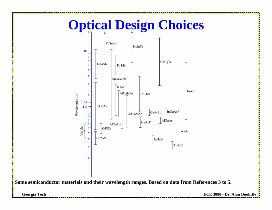
Some semiconductor materials and their wavelength ranges. Based on data from References 3 to 5.
Optical Design Choices

ECE 3080 - Dr. Alan DoolittleGeorgia Tech
P-n Junction I-V Characteristics
Electron Diffusion Current
Electron Drift Current
Hole Diffusion Current
Hole Drift Current
In Equilibrium, the Total current balances due to the sum of the individual components

ECE 3080 - Dr. Alan DoolittleGeorgia Tech
Electron Diffusion CurrentElectron Drift
Current
Hole Diffusion Current
Hole Drift Current
Current flow is proportional to e(Va/Vref) due to the exponential decay of carriers into the majority carrier bands
Review: p-n Junction I-V Characteristics
Current flow is dominated by majority carriers flowing across the junction and becoming minority carriers
QuickTime Movie

ECE 3080 - Dr. Alan DoolittleGeorgia Tech
Electron Diffusion Current negligible due to large energy barrier
Electron Drift Current
Hole Diffusion Current negligible due to large energy barrier
Hole Drift Current
Current flow is constant due to thermally generated carriers swept out by E-fields in the depletion region
Current flow is dominated by minority carriers flowing across the junction and becoming majority carriers
QuickTime Movie
Review: p-n Junction I-V Characteristics

ECE 3080 - Dr. Alan DoolittleGeorgia Tech
Where does the reverse bias current come from? Generation near the depletion region edges “replenishes” the current source.
Review: p-n Junction I-V Characteristics
ECE 3080 - Dr. Alan DoolittleGeorgia Tech
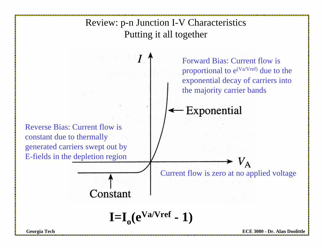
Review: p-n Junction I-V CharacteristicsPutting it all together
Reverse Bias: Current flow is constant due to thermally generated carriers swept out by E-fields in the depletion region
Forward Bias: Current flow is proportional to e(Va/Vref) due to the exponential decay of carriers into the majority carrier bands
Current flow is zero at no applied voltage
I=Io(eVa/Vref - 1)

ECE 3080 - Dr. Alan DoolittleGeorgia Tech
Light Emitting Devices – Basics• Emission of photons by recombination of electrons and holes in direct
bandgap materials• Photoluminescense: excess electrons and holes required for the radiative
recombination are generated by photon absorption• Electroluminescense: excess electrons and holes required for the radiative
recombination are result of an electrical current
www.osram.com
Slide Credit to Dr. Oliver Brandt, Ga Tech
ECE 3080 - Dr. Alan DoolittleGeorgia Tech
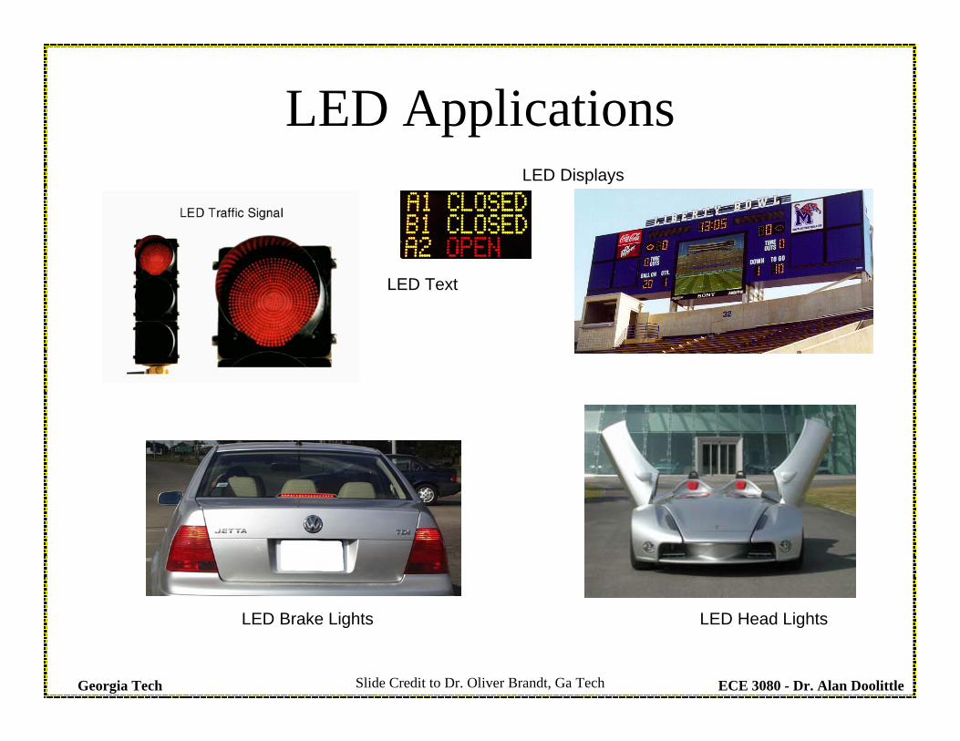
LED ApplicationsLED Displays
LED Brake Lights LED Head Lights
LED Text
Slide Credit to Dr. Oliver Brandt, Ga Tech
ECE 3080 - Dr. Alan DoolittleGeorgia Tech
… and at Georgia Tech?
Slide credited to Dr. Oliver Brandt, Ga Tech

ECE 3080 - Dr. Alan DoolittleGeorgia Tech
Diode Applications: LED or a Laser Diode
R=1000 ohms
V=9V VA
I V1=IR Light Emission under forward Bias
Diode made from a direct bandgap semiconductor. Note: These devices may not be a simple p-n type diode, but behave electrically identical to a p-n junction diode.
Majority Carriers that are injected to the opposite side of the diode under forward bias become minority carriers and recombine. In a direct bandgap material, this recombination can result in the creation of photons. In a real device, special areas are used to trap electrons and holes to increase the rate at which they recombine. These areas are called quantum wells.
LightFN
FP
-qVA
Quantum well made from smaller bandgap material
Electron Current
Hole Current
P-type Al0.5Ga0.5As
N-type Al0.5Ga0.5As
GaAs
ECE 3080 - Dr. Alan DoolittleGeorgia Tech
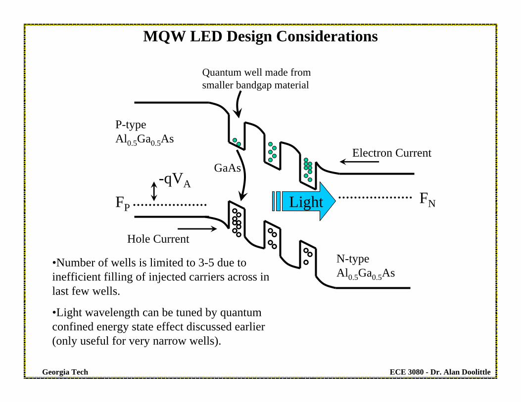
MQW LED Design Considerations
Light FNFP
-qVA
Quantum well made from smaller bandgap material
Electron Current
Hole Current
P-type Al0.5Ga0.5As
N-type Al0.5Ga0.5As
GaAs
•Number of wells is limited to 3-5 due to inefficient filling of injected carriers across in last few wells.
•Light wavelength can be tuned by quantum confined energy state effect discussed earlier (only useful for very narrow wells).

ECE 3080 - Dr. Alan DoolittleGeorgia Tech
MQW LED Design Considerations
Nakamura, S. et al., “High-power InGaN single-quantum-well-structure blue and violetlight-emitting diodes,” Appl. Phys. Lett 67, 1868 (1995).
•The shape of the “die” (chip) can greatly aid light extraction by minimizing internal reflections

ECE 3080 - Dr. Alan DoolittleGeorgia Tech
Homojunction LED Design Considerations
Light
FN
FP
-qVA
Electron Current
Hole Current
P-type GaP
N-type GaPZn
O
•Efficient light generation results from Donor-Acceptor pair transition – requires high doping level so Donor and acceptor are “close to each other”.

ECE 3080 - Dr. Alan DoolittleGeorgia Tech
Blue LED based on AlGaInN
• AlGaInN: direct bandgap ranging from 0.65 eV to 6.2 eV corresponding towavelength from 1.9 µm to 0.2 µm
• Challenge: find lattice-matched substrateSolution: sapphire substrate with AlN buffer layer
• Because sapphire is non-conducting, both contacts are from the surface• Blue light originates from radiative recombination in the GaxIn1-xN layer
Sze, Figure 9.10
Slide Credit to Dr. Oliver Brandt, Ga Tech
ECE 3080 - Dr. Alan DoolittleGeorgia Tech
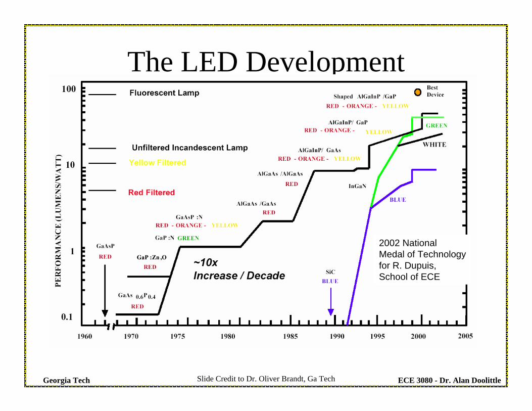
The LED Development
2002 NationalMedal of Technologyfor R. Dupuis,School of ECE
Slide Credit to Dr. Oliver Brandt, Ga Tech

ECE 3080 - Dr. Alan DoolittleGeorgia Tech
How to Make White LEDs?
Slide Credit to Dr. Oliver Brandt, Ga Tech

ECE 3080 - Dr. Alan DoolittleGeorgia Tech
Photodiode
Reversed Bias Diode with no light illumination
Reversed Bias Diode WITH light illumination results in “extra” drift current due to photogenerated ehp’s
that can reach the junction.

ECE 3080 - Dr. Alan DoolittleGeorgia Tech
( )( ) LPNoV
V
ototal
LighttoDueV
V
ototal
LighttoDuedarktotal
GLWLqAIeII
IeII
III
TD
TD
++−+⎟⎟⎠
⎞⎜⎜⎝
⎛−=
+⎟⎟⎠
⎞⎜⎜⎝
⎛−=
+=
⎟⎠⎞⎜
⎝⎛
⎟⎠⎞⎜
⎝⎛
1
No-LightLight
Light
No-Light
Bias Point
I
V
Photodiode Every EHP created within the depletion region (W) and within a diffusion length away from the depletion region is collected (swept across the junction by the electric field) as photocurrent (current resulting from light). All other EHP’s recombine before they can be collected.
ECE 3080 - Dr. Alan DoolittleGeorgia Tech
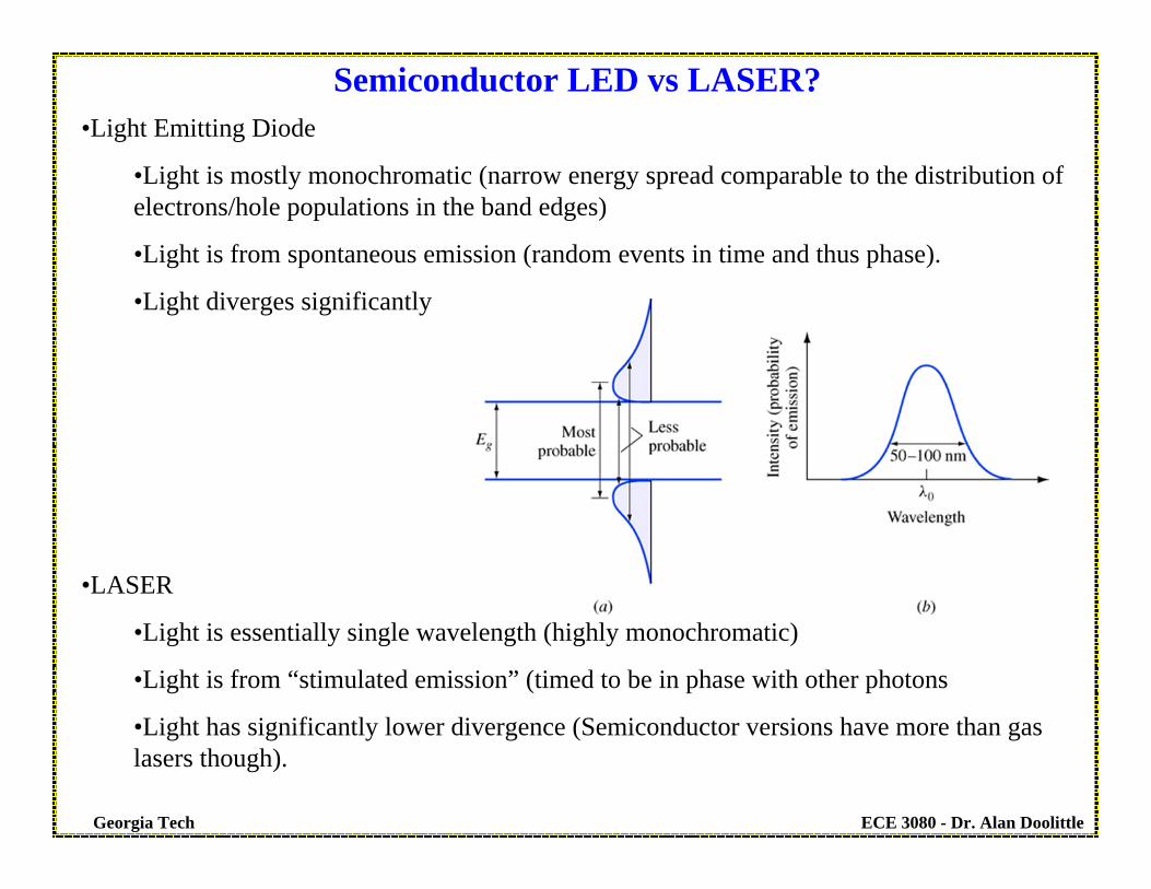
•Light Emitting Diode
•Light is mostly monochromatic (narrow energy spread comparable to the distribution of electrons/hole populations in the band edges)
•Light is from spontaneous emission (random events in time and thus phase).
•Light diverges significantly
•LASER
•Light is essentially single wavelength (highly monochromatic)
•Light is from “stimulated emission” (timed to be in phase with other photons
•Light has significantly lower divergence (Semiconductor versions have more than gas lasers though).
Semiconductor LED vs LASER?

ECE 3080 - Dr. Alan DoolittleGeorgia Tech
Present LED technology is more efficient than even fluorescent lamps! However, it will take some time before the cost comes down enough to replace light bulbs.
LED History

ECE 3080 - Dr. Alan DoolittleGeorgia Tech
LED
•A pn junction in a direct bandgap material will produce light when forward biased. However, re-absorption (photon recycling) is likely and thus should be avoided.•Use of quantum wells in the “active region” (region where minority carriers are injected and recombine from the “majority carrier” anode (source of holes) and cathode (source of electrons) results in minimal re-absorption since the emitted light is below the bandgap of the cladding layers (higher bandgap regions).•The quantum well also strongly confines the electrons and holes to the same region of the material enhancing the probability of recombination and thus enhancing the radiation efficiency (light power out/electrical power in).
ECE 3080 - Dr. Alan DoolittleGeorgia Tech
LED
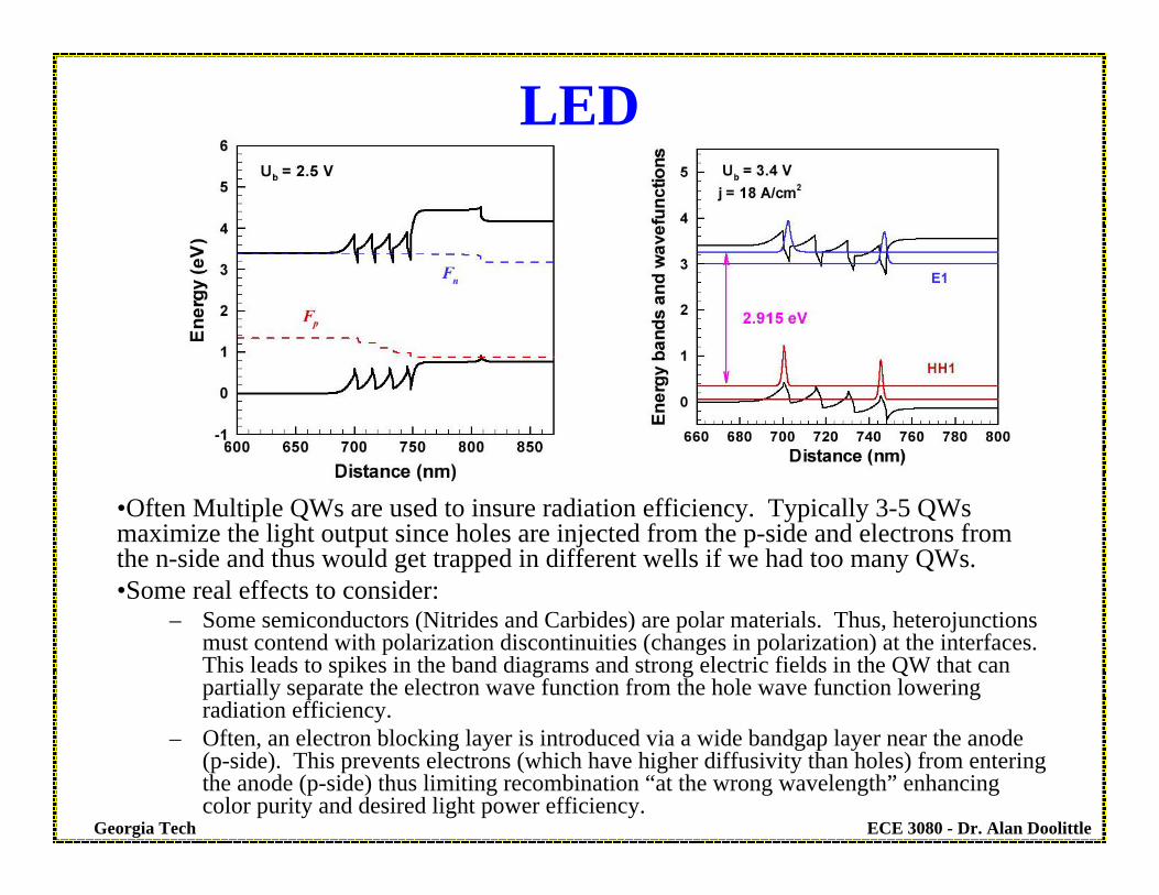
•Often Multiple QWs are used to insure radiation efficiency. Typically 3-5 QWsmaximize the light output since holes are injected from the p-side and electrons from the n-side and thus would get trapped in different wells if we had too many QWs.•Some real effects to consider:
– Some semiconductors (Nitrides and Carbides) are polar materials. Thus, heterojunctions must contend with polarization discontinuities (changes in polarization) at the interfaces. This leads to spikes in the band diagrams and strong electric fields in the QW that can partially separate the electron wave function from the hole wave function lowering radiation efficiency.
– Often, an electron blocking layer is introduced via a wide bandgap layer near the anode (p-side). This prevents electrons (which have higher diffusivity than holes) from entering the anode (p-side) thus limiting recombination “at the wrong wavelength” enhancing color purity and desired light power efficiency.
ECE 3080 - Dr. Alan DoolittleGeorgia Tech
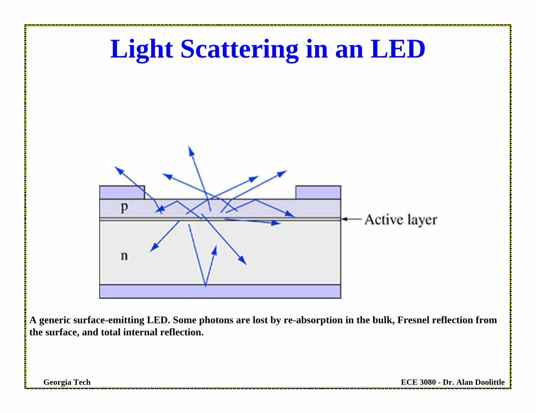
A generic surface-emitting LED. Some photons are lost by re-absorption in the bulk, Fresnel reflection fromthe surface, and total internal reflection.
Light Scattering in an LED
ECE 3080 - Dr. Alan DoolittleGeorgia Tech
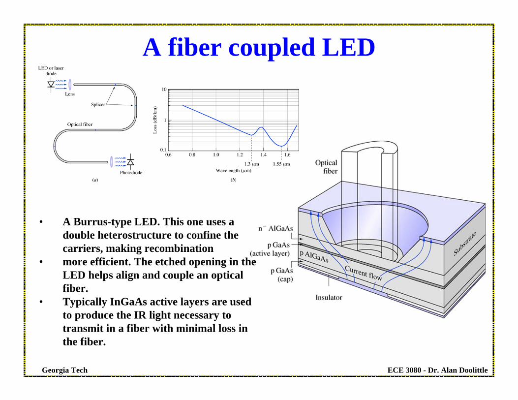
• A Burrus-type LED. This one uses a double heterostructure to confine the carriers, making recombination
• more efficient. The etched opening in the LED helps align and couple an optical fiber.
• Typically InGaAs active layers are used to produce the IR light necessary to transmit in a fiber with minimal loss in the fiber.
A fiber coupled LED
ECE 3080 - Dr. Alan DoolittleGeorgia Tech
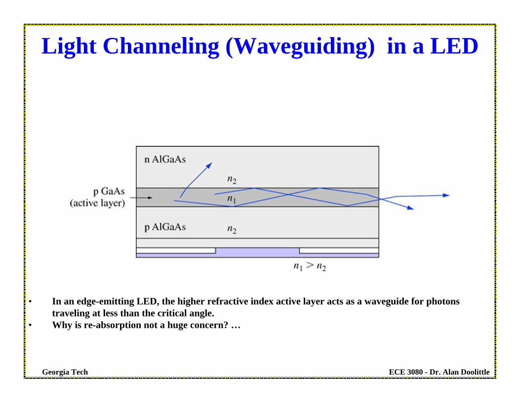
• In an edge-emitting LED, the higher refractive index active layer acts as a waveguide for photons traveling at less than the critical angle.
• Why is re-absorption not a huge concern? …
Light Channeling (Waveguiding) in a LED

ECE 3080 - Dr. Alan DoolittleGeorgia Tech
• The edge-emitting LED’s waveguide (a) supports only certain transverse modes, whose field distributions are shown in (b). In practice, only the first mode is allowed. It is not completely confined to the active layer, thus its absorption is reduced.
LED Waveguides (edge emitting LED)

ECE 3080 - Dr. Alan DoolittleGeorgia Tech
• We can add to our understanding of absorption and spontaneous radiation due to random recombination another form of radiation – Stimulated emission.
• Stimulated emission can occur when we have a “population inversion”, i.e. when we have injected so many minority carriers that in some regions there are more “excited carriers” (electrons) than “ground state” carriers (holes).
• Given an incident photon of the bandgap energy, a second photon will be “stimulated”by the first photon resulting in two photons with the same energy (wavelength) and phase.
• This phase coherence results in minimal divergence of the optical beam resulting in a directed light source.
Spontaneous Light Emission
ECE 3080 - Dr. Alan DoolittleGeorgia Tech
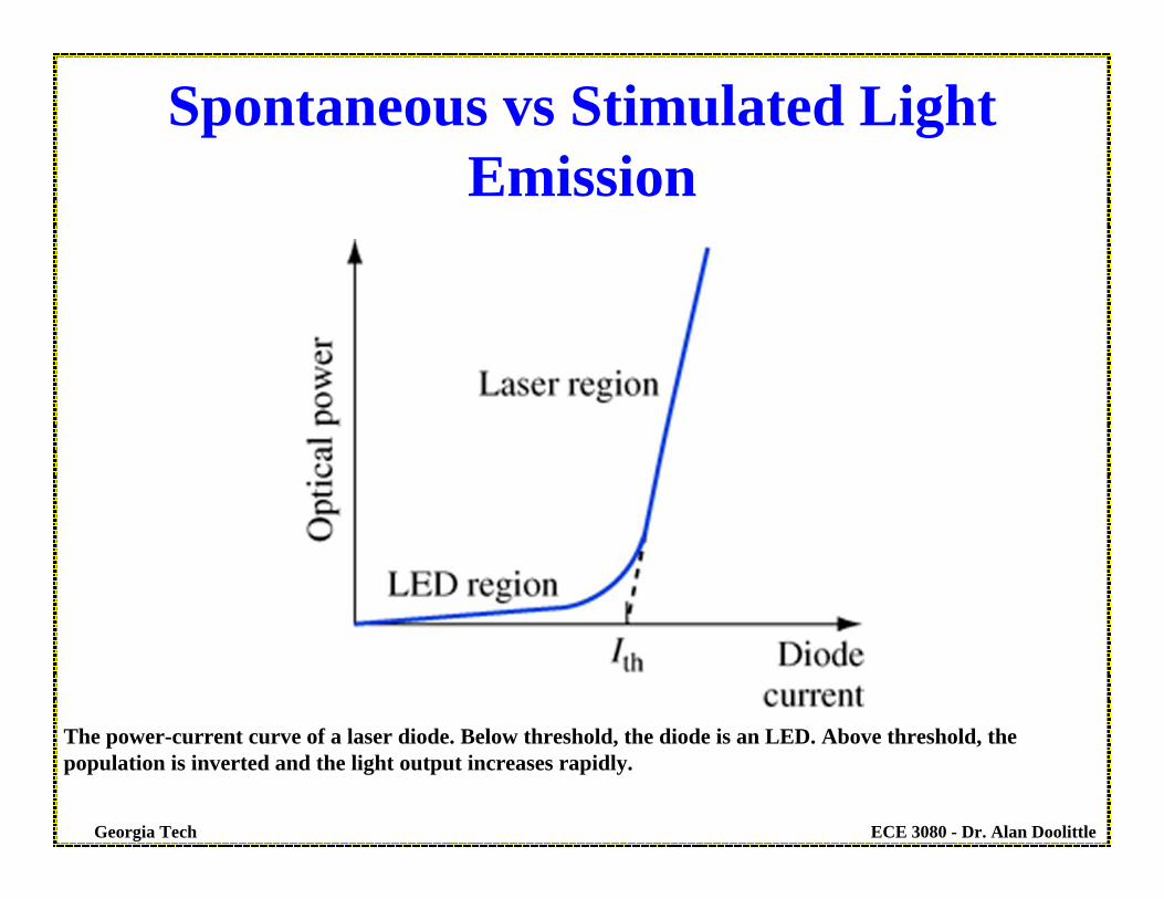
The power-current curve of a laser diode. Below threshold, the diode is an LED. Above threshold, thepopulation is inverted and the light output increases rapidly.
Spontaneous vs Stimulated Light Emission

ECE 3080 - Dr. Alan DoolittleGeorgia Tech
The ends of the chip form partially reflective mirrors, which allows the photons to be reflected back andforth and thus be exposed to gain for a longer period of time.
Using Mirrors and Optical Gain (through Stimulated emission) to
“Amplify the Light”
ECE 3080 - Dr. Alan DoolittleGeorgia Tech
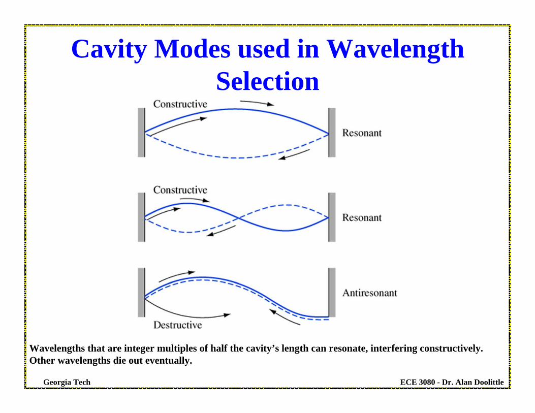
Wavelengths that are integer multiples of half the cavity’s length can resonate, interfering constructively. Other wavelengths die out eventually.
Cavity Modes used in Wavelength Selection
ECE 3080 - Dr. Alan DoolittleGeorgia Tech
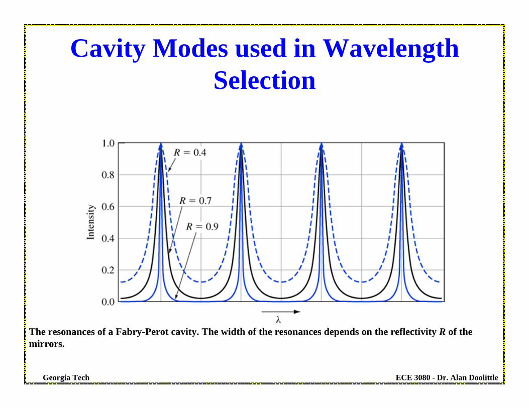
The resonances of a Fabry-Perot cavity. The width of the resonances depends on the reflectivity R of themirrors.
Cavity Modes used in Wavelength Selection
ECE 3080 - Dr. Alan DoolittleGeorgia Tech
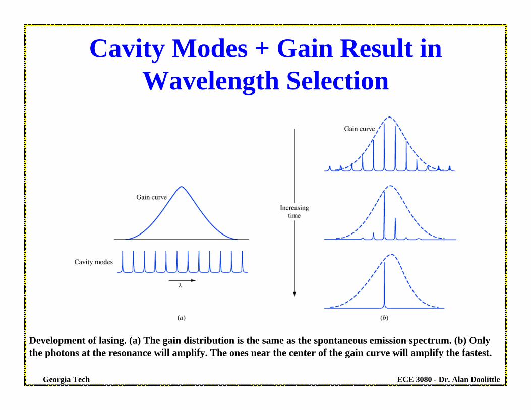
Development of lasing. (a) The gain distribution is the same as the spontaneous emission spectrum. (b) Onlythe photons at the resonance will amplify. The ones near the center of the gain curve will amplify the fastest.
Cavity Modes + Gain Result in Wavelength Selection
ECE 3080 - Dr. Alan DoolittleGeorgia Tech
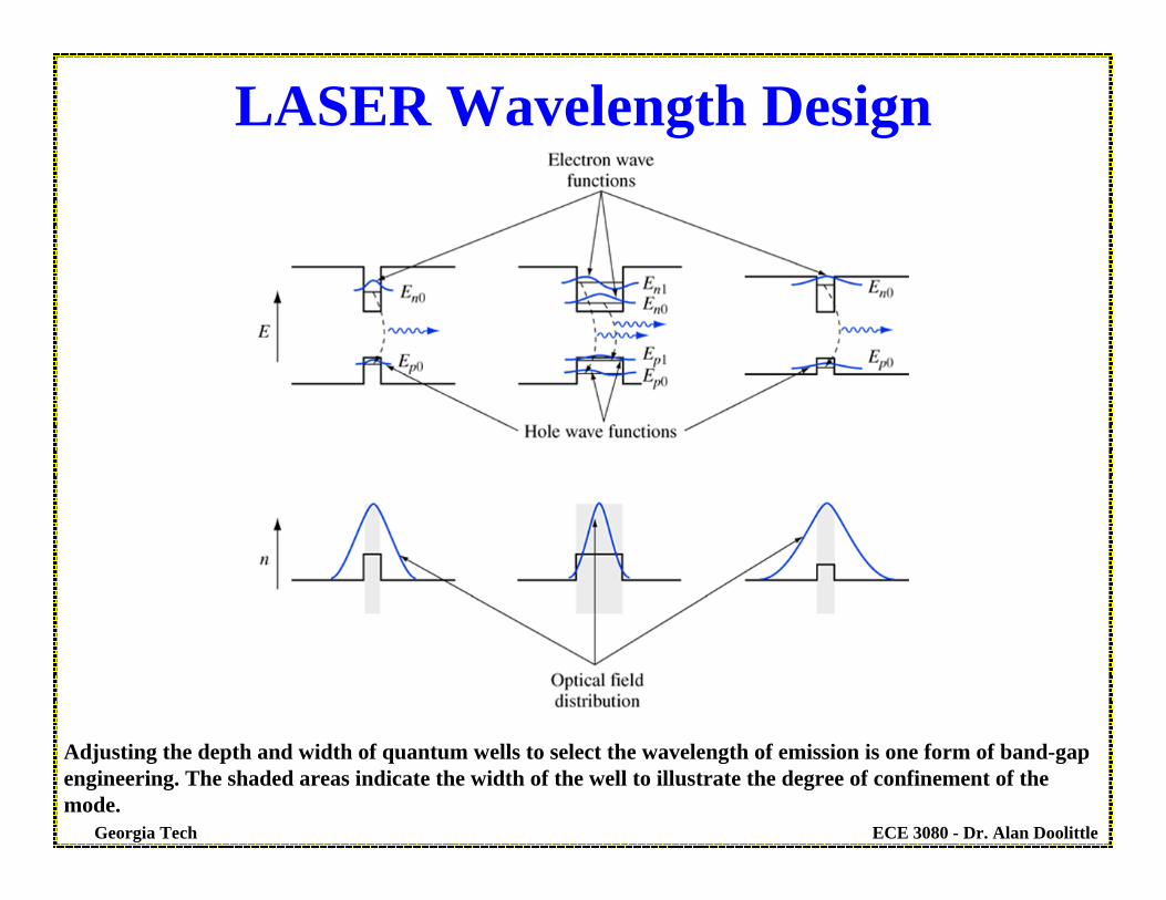
Adjusting the depth and width of quantum wells to select the wavelength of emission is one form of band-gapengineering. The shaded areas indicate the width of the well to illustrate the degree of confinement of themode.
LASER Wavelength Design

ECE 3080 - Dr. Alan DoolittleGeorgia Tech
The output pattern of a simple “stripline”, edge-emitting laser is elliptical and widely divergent.
Stripline or Edge Emitting LASER
ECE 3080 - Dr. Alan DoolittleGeorgia Tech
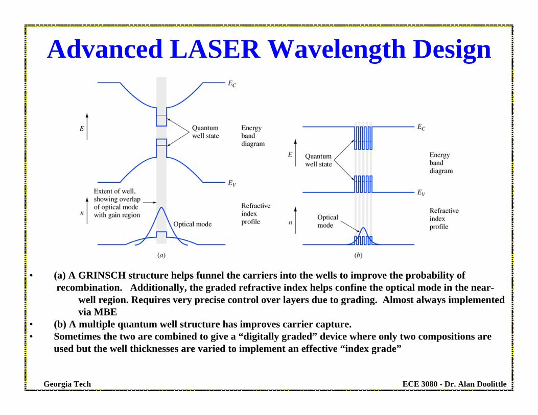
• (a) A GRINSCH structure helps funnel the carriers into the wells to improve the probability of recombination. Additionally, the graded refractive index helps confine the optical mode in the near-
well region. Requires very precise control over layers due to grading. Almost always implemented via MBE
• (b) A multiple quantum well structure has improves carrier capture.• Sometimes the two are combined to give a “digitally graded” device where only two compositions are
used but the well thicknesses are varied to implement an effective “index grade”
Advanced LASER Wavelength Design

ECE 3080 - Dr. Alan DoolittleGeorgia Tech
• A vertical cavity surface-emitting laser. (After Ueki et al., IEEE Photonics Technology Letters, 11, no. 12, pp. 1539–1541, 1999, © IEEE.)
• Distributed Bragg Reflectors (DBR) mirrors require very precise growth control. Refreactive index is varied as much as possible (while still remaining electrically conductive) and must be a precise fraction of a wavelength
Vertical Cavity Surface Emitting Laser (VECSEL)

ECE 3080 - Dr. Alan DoolittleGeorgia Tech
The distributed feedback (DFB) laser uses a grating to provide continuous feedback along the laser cavity.
DFB LASER


