The Drive & Control Company
Linear Motion Slides R310EN3001 (1999.07)

3R310EN 3001 (1999.07)
Linear Motion Slides
A Solution to Many Problems 4
Product Overview 6
Structure 12
Technical Data 14
Load Capacities and Moments 15
General Information 16
Technical Notes 18
- Size 8-65/12-85 18
- Size 16-100/20-130 20
- Size 25-160/30-180 22
- Size 40-230/50-280 24
Linear Motion Slides, Closed Type without Drive Unit 26
Linear Motion Slides, Closed Type with Ball Screw Drive 30
Linear Motion Slides, Open Type without Drive Unit 38
Linear Motion Slides, Open Type with Ball Screw Drive 42
Motor Attachment 50
Linear Motion Slides with Toothed Belt Drive 52- Structure and Technical Data 52
Switch Mounting Arrangements 60
Motors 63
Documentation 66
Inquiry/Order Form 67

4 R310EN 3001 (1999.07)
Linear Motion Slides
• Driving
• Transporting
• Positioning
The tasks
Length up to 5300 mm
Load capacity C up to 36380 NLoad capacities and moments Longitudinal moment ML up to 3011 Nm Torsional moment Mt up to 2740 Nm
Static load up to 1000 kg
Speed up to 80 m/min
Precision
Standard reportDocumentation Moment of friction measurement Lead deviation
A Solution to Many Problems
System completewith drive unit
Switch mounting arrangements
Version
Total height 23 mm to 115 mm

5R310EN 3001 (1999.07)
The solution
LinearMotion Slides
Length up to 5300 mm
Load capacity C up to 36380 NLoad capacities and moments Longitudinal moment ML up to 3011 Nm Torsional moment Mt up to 2740 Nm
Static load up to 1000 kg
Speed up to 80 m/min
Standard reportDocumentation Moment of friction measurement Lead deviation
A Solution to Many Problems
Total height 23 mm to 115 mm
Repeatability of up to 0.005 mmPositioning accuracy of up to 0.01 mm
AC servomotor, MiniDrive or stepping motorwith motor mount, coupling or side drive withtiming belt (plus control unit)
Switch over total travel range
without drive unitwith ball screw drivewith toothed belt drive

6 R310EN 3001 (1999.07)
Product Overview
Linear Motion Slides:
closed type - for cantilever-type installation
open type - for installation with shaft support rails
Particularly smooth running and long service life thanks to Super Linear Bushings
Lubrication points at both sides of the carriage, for grease lubrication only
Oil and moisture-proof PU bellows-type protective cover (the last fold is mechanically clamped)
without drive unit
Various possibilities for motor attachment
with Precision Ball Screw Assembly
Higher travel speeds possible with larger ball screw drives
One-point lubrication
Linear Motion Slides

7R310EN 3001 (1999.07)
without drive unit
Longer stroke for specified length
Precision Ball Screw Assembly in rolled quality. Tolerance class T7 ac-cording to DIN 69051 with clearance-free cylindrical nut
Tension end enclosure with inte-gral belt tensioning system. Belt pulley system with ball bearings lubricated for life
Wide, steel-reinforced toothed polyurethane drive belt for extreme stiffness and positioning accuracy requirements
with toothed belt drive
Length as desired
with toothed belt driveScrew Drive
Optimized shaft clamping force
Revised designGreater flexi- bility due to options. Ready for installation with different attachments

8 R310EN 3001 (1999.07)
Product OverviewLinear Motion Slides
VRDM 368 VRDM 397 VRDM 3910 VRDM 3913
MKD 25B-144-KG1 MKD 41B-144 KG1 MKD 71B-061 KG1 MKD 71B-097 KG1
MMD 022A MMD 042A MMD 082A
MiniDrive
Digital AC servomotor
3-phase stepping motor
Motor Selectionin accordance with controllers and control systems
A choice can be made between several different motor/controller combinations to achieve the most cost-efficient solution for each customer application. The motor/con-troller combination must always be taken into account when sizing the drive.
For more detailed information on motors and control systems, please refer to catalog RE 82700 “Controllers, Motors, Electrical Accessories”.
9R310EN 3001 (1999.07)
ckksteupt.epsckksteupt.eps
ckksteupt.epsckksteupt.eps
ckkdmd1mt.eps
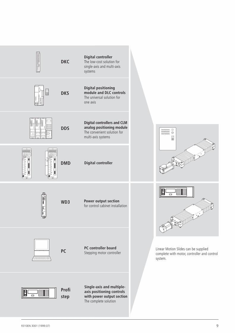
Digital controller
RS232
Auto
Hand
STAR step
Digital controllerThe low-cost solution for single-axis and multi-axis systems
Digital positioning module and DLC controlsThe universal solution for one axis
Digital controllers and CLM analog positioning moduleThe convenient solution for multi-axis systems
Power output sectionfor control cabinet installation
PC controller boardStepping motor controller
Single-axis and multiple- axis positioning controls with power output sectionThe complete solution
ckkschaltpt.eps
Linear Motion Slides can be supplied complete with motor, controller and control system.
Profi step
PC
WD3
DMD
DDS
DKS
DKC
RS232
Auto
Hand
STAR step
RS232
Auto
Hand
STAR step

10 R310EN 3001 (1999.07)
Product OverviewType designation (size)The linear motion slides are designated according to type and size.
The term slide is used to describe a speci-fic combination of type and size.
“Linear motion slide” is abbreviated to slide in the following tables.
Slide (example) =
System = Linear Motion Slide (S) Guideway = Closed-type linear bushing (G) Open-type linear bushing (O) Drive unit = Without drive unit (O) Precision Ball Screw Assembly (K) Toothed belt (R)
Dimensions of guideway =
Overallwidth =
Type
S G K 16- 100
d
B
SGK
SGO
SGR
Type Slide Guideway Drive unit
Linear Motion SlidesClosed type
SOK
SOO
SOR
Toothed belt drive
Toothed belt drive
Precision Ball Screw Assem-bly
Precision Ball Screw Assem-bly
Linear Motion SlidesOpen type
without drive unit
without drive unit
Super Linear Bushing A open type
Super Linear Bushing A closed type
1) Size 8-65 with Standard Linear Bushing
PictoAntrieb2.eps
11.01.94
PictoAntrieb2.eps
11.01.94
Linear Motion Slides
Size

11R310EN 3001 (1999.07)
As far as the desired service life is con-cerned, loads of up to approximately 20% of the dynamic load and moment values (C, Mt, ML) have proved acceptable.
The following values may not be exceeded:
Suitable load(recommended value on the basis of past experience)
– the maximum permissible deflection
– the maximum permissible drive torque
Size: d-B
Page 26 1040 2500 3050 6040 11820 14360 24660 36060
Page 30 2500 3050 6040 11820 14360 24660 36060
Page 56 11820
Page 40 2850 3440 6100 11950 14520 24950 36380
Page 56 11950
Page 44 2850 3440 6100 11950 14520 24950 36380
Dynamic load capacity C (N)
Bd
The dynamic load capacities and moments are based on 100,000 m travel. However, a travel of just 50,000 m is often taken as a basis. If this is the case, for comparison purposes:
Multiply values C, Mt and ML by 1.26.
Note on dynamic load capacities and moments:
8-65 12-85 16-100 20-130 25-160 30-180 40-230 50-280
12 R310EN 3001 (1999.07)
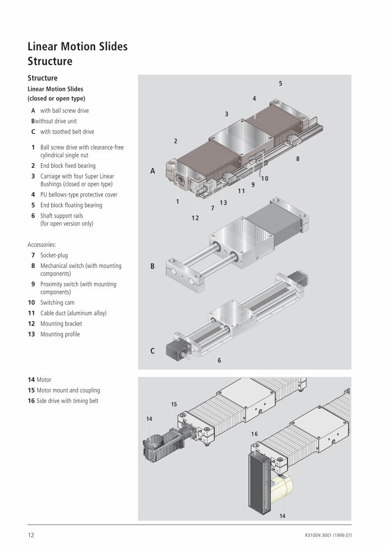
StructureStructureLinear Motion Slides (closed or open type)
A with ball screw drive
B without drive unit
C with toothed belt drive
1 Ball screw drive with clearance-free cylindrical single nut
2 End block fixed bearing
3 Carriage with four Super Linear Bushings (closed or open type)
4 PU bellows-type protective cover
5 End block floating bearing
6 Shaft support rails(for open version only)
Accessories:
7 Socket-plug
8 Mechanical switch (with mounting components)
9 Proximity switch (with mounting components)
10 Switching cam
11 Cable duct (aluminum alloy)
12 Mounting bracket
13 Mounting profile
14 Motor
15 Motor mount and coupling
16Side drive with timing belt
Linear Motion Slides
1
2
3
4
5
11
7
8
910
12
13
6
A
B
C
15
14
16
14
13R310EN 3001 (1999.07)
Structure
2 31 4
6
7
Fv
4
1
3
5
8
2
9
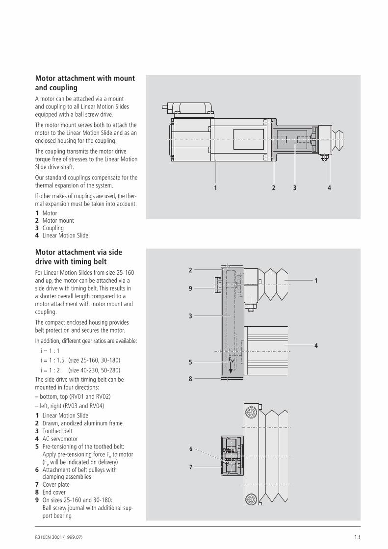
Motor attachment via side drive with timing belt For Linear Motion Slides from size 25-160 and up, the motor can be attached via a side drive with timing belt. This results in a shorter overall length compared to a motor attachment with motor mount and coupling.
The compact enclosed housing provides belt protection and secures the motor.
In addition, different gear ratios are available:
i = 1 : 1 i = 1 : 1.5 (size 25-160, 30-180)
i = 1 : 2 (size 40-230, 50-280)The side drive with timing belt can be mounted in four directions:– bottom, top (RV01 and RV02)– left, right (RV03 and RV04)
1 Linear Motion Slide2 Drawn, anodized aluminum frame3 Toothed belt4 AC servomotor5 Pre-tensioning of the toothed belt: Apply pre-tensioning force Fv to motor (Fv will be indicated on delivery)6 Attachment of belt pulleys with
clamping assemblies7 Cover plate8 End cover9 On sizes 25-160 and 30-180:
Ball screw journal with additional sup-port bearing
Motor attachment with mount and couplingA motor can be attached via a mount and coupling to all Linear Motion Slides equipped with a ball screw drive.
The motor mount serves both to attach the motor to the Linear Motion Slide and as an enclosed housing for the coupling.
The coupling transmits the motor drive torque free of stresses to the Linear Motion Slide drive shaft.
Our standard couplings compensate for the thermal expansion of the system.
If other makes of couplings are used, the ther-mal expansion must be taken into account.1 Motor2 Motor mount3 Coupling4 Linear Motion Slide
14 R310EN 3001 (1999.07)
Technical DataLinear Motion Slides
1700
1600
2900
250 84
20 x 5 20 x 20 25 x 10
2.6
6.9
5.0
1.7
4.6
3.3
0.4
Permissible torque up to length L = ... at (1)
Reduced mass moment of inertia at
(· 10-6 kgm2)(· 10-6 kgm2)
i = 1.5i = 1i = 1.5i = 1
(Nm)(Nm)(mm)
MRvL MRv JRv JRvBallscrewLinearMotionSlide
Motor
Friction moment MRRv (Nm)
Gear ratio i = ...
MKD71B
0.45
Permissible torque up to length L = ... at (1)
Reduced mass moment of inertia at
(· 10-6 kgm2)(· 10-6 kgm2)
i = 2i = 1i = 2i = 1
(Nm)(Nm)(mm)
MRvL MRv JRv JRv
Technical data of AC servomotors and MiniDrive
MKD41B-144KG1Motor
170 + 16
2.2
4.65
2.7
Maximumeffectivespeednmax (1/min)
RatedtorqueMMN (Nm)
MaximumtorqueMmax (Nm)
MassmomentofinertiaJM+JBr (10-6kgm2)
BrakeholdingtorqueMBr (Nm)
MasswithbrakemBr (kg)
MKD71B-061
870 + 38
5
9.17
8
d0 x P
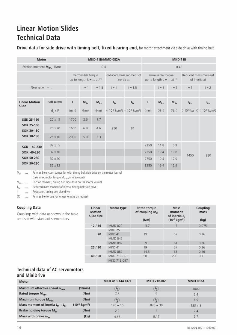
Drive data for side drive with timing belt, fixed bearing end, for motor attachment via side drive with timing belt
MRv … Permissible system torque for with timing belt side drive on the motor journal
(take max. motor torque MMmax into account)
MRRv … Friction moment, timing belt side drive on the motor journal
JRv … Reduced mass moment of inertia, timing belt side drive
i … Reduction, timing belt side drive
(1) … Permissible torque for longer lengths on request
MKD41B/MMD082A
SGK25-160
SOK25-160
SOK30-180
SOK30-180
SGK40-230
SOK40-230
SOK50-280
SOK50-280
32 x 5
32 x 10
32 x 20
32 x 32
2250
2250
2750
3250
11.8
19.4
19.4
19.4
5.9
10.8
12.9
12.9
1450 280
MMD082A
3000
2.4
6.9
133 + 8
2.4
3.7
Coupling Data
Couplings with data as shown in the table are used with standard servomotors.
Linear Motortype Ratedtorque Mass Coupling Motion ofcouplingMK moment mass Slidesize ofinertiaJK (Nm) (10-6kgm2) (kg)
12/16 MMD 022 3.7 7 0.075 MKD 25 20 MKD 41 19 57 0.26 MMD 042 MMD 082 9 61 0.26 25/30 MKD 41 19 57 0.26 MMD 082 14.5 63 0.26 40/50 MKD 71B-061 50 200 0.7 MKD 71B-097

15R310EN 3001 (1999.07)
Closedtype
Sized-B
Dynamicmoments
Mt(Nm) ML(Nm)
Dynamicloadcapacity
C(N)
Opentype
Dynamicloadcapacity
C(N) 8- 65 1040 16 15
12- 85 2500 52 57
16-100 3050 82 87
20-130 6040 217 229
25-160 11820 520 549
30-180 14360 689 725
40-230 24660 1504 1713
50-280 36060 2740 3011
2850 25 27
3440 39 41
6100 134 141
11950 320 339
14520 425 447
24950 928 1057
36380 1687 1853
Reduced load capacity in short-stroke applications
In short-stroke applications, the service life of the shafts is shorter than that of the Super Linear Bushings.
For this reason, the load capacities list ed in the tables must be multiplied by the factor fw.
MtML
C
B
d
B
MtML
Cd
C'
C' Sizes 12 and 16 C‘ = 0.42 · C
Sizes 20 to 50 C‘ = 0.6 · C
PL = ( )3· 105
Lh = L
C
60 · vm
L nominal service life (m)
Lh nominal service life (h)
C dynamic load capacity (N)
P equivalent dynamic load (N)
vm average speed (m)
Note on dynamic load capacities and moments
The dynamic load capacities and moments are based on 100,000 m travel. However, a travel of just 50,000 m is often taken as a basis. If this is the case, for comparison purposes:
Multiply values C, Mt and ML by 1.26.
Nominal service life
The load capacities of the open versions are reduced as follows under lift-off loads:
Sizes 12 and 16 to 42%
Sizes 20 to 50 to 60%
Dynamicmoments
Mt(Nm) ML(Nm)
Load Capacities and Moments
12 16 20 25 30 40 50
0 20 40 60 80 100 120 140 180 200 220 240 260160
1,0
0,9
0,8
0,7
0,6
0,5
fw
Stroke(mm)

16 R310EN 3001 (1999.07)
Linear Motion SlidesGeneral Information
tan αmax = 8.72 · 10-3 =̂ 0.5°
tan α ≤ tan αmax
Linear Motion Slides are also available with:
- corrosion resistant steel shafts to DIN 17230 / EN 10088
- Resist steel shafts: zinc/iron coating with yellow chromating
For further details on Resist, please ask for catalog RE 82 050.
For further details on Linear Bushings and Precision Steel Shafts, please ask for catalog RE 83 100.
Delivered as separate parts. The carriage is mounted as a sub-assembly. The fixing screws are not included in the package.
Open Type SOO:
The Precision Steel Shafts are screwed to the Shaft Support Rails.
tan αmax = 10 · 10-4Size 8-65:
Assemblies without drive unit:
Delivery condition:
Length L:
Assemblies with drive unit: The Linear Motion Slides with ball screw drive and toothed belt drive (SGK, SGR, SOR and SOK) are delivered fully assembled and greased.
Linear Motion Slides consist of components of varying length and assemblies of fixed length. The length-dependent components are cut to size to suit each particular appli-cation. Linear Motion Slides can thus be custom-designed and completed in a variety of lengths (infinitely variable). Lengths exceeding the specified maximum Lmax are available on request.
Permissible shaft deflection in the Linear Bushing closed type:
Due to the use of Super Linear Bushings (except for Linear Motion Slide size 8-65), higher shaft deflection is permissible than for conventional linear bearings. Selection of the length (L) and the size of slide should take account of the permissible shaft deflection (tan α).
Maximum permissible drive torque Mper:
The values of Mper given in the graphs (see Technical Notes) are based on the follow ing assumptions:
• Horizontal operation
• No radial load on the ball screw drive journal
• The torque rating of the coupling is not taken into account
The maximum permissible drive torque (see Technical Notes) is reduced for ball screw drives with keyway. The keyway produces a notch effect and reduces the effective dia -meter. (Information on side drive with timing belt available on request.)
Weight of the Linear Motion Slide:
Shafts for Linear Motion Slides without drive unit:
Weight calculation does not include motor attachment, switches or side drive with timing belt.
Weight (kg/mm) ∙ Length L (mm) + Weight of all fixed-length components (kg)

17R310EN 3001 (1999.07)

18 R310EN 3001 (1999.07)
Linear Motion Slides
L/2
L
F
α
tan α ≤ tan αmax
Technical Notes – Size 8-65/12-85
8-65 Slide
Dynamicloadcapacity
C(N)
Dynamicmoments
Mt(Nm)
ML(Nm)
Movedmass
(kg)
Frictionalforce
(N)
Closedtype
SlideweightLinmm(kg)
Max.lengthLmax
(mm)
tan α = F · (L - 9) · 4.970 · 10-8
tan αmax = 10 · 10-4
Permissible shaft deflection in the Linear Bushing1)
tan α Shaft deflectionF External load (N)L Dimension “L” (mm)
Linear Motion Slide SGO 8 - 65 incorpora-tes Standard Linear Bushings. The load capacity or service life of the Slide will therefore be reduced with increasing shaft deflection.
For further information refer to catalog RE 83 100 “Linear Bushings and Shafts”.
SGO 8-65 1040 16 15 0.28 0.0008 · L + 0.39 700 3
See section on Load Capacities and Moments.
1) Also refer to “General Information”

19R310EN 3001 (1999.07)
12-85 Slide
Closedtype
Opentype
Ballscrewd0xP(mm)
Dynamicloadcapacity Dyn.moments
Mt(Nm)
ML(Nm)
Movedmass
(kg)
SlideweightLinmm(kg)
MaximumlengthLmax
(mm)
Guide-way(N)
Fixedbearing(N)
Ballscrew(N)
SGO12-85 2500 52 57 0.55 0.0018 · L + 0.80 1000
SGK12-85 8x2.5 2500 5280 2900 52 57 0.54 0.0021 · L + 0.92 1000
SOO12-85 2850 25 27 0.47 0.0035 · L + 0.47 4000
SOK12-85 8x2.5 2850 5280 2900 25 27 0.47 0.0040 · L + 0.82 1000
Permissible shaft deflection in the Linear Bushing closed type1): tan α = F · (L - 18) · 1.376 · 10-8
tan αmax = 8.72 · 10-3
Linear Motion Slides with Ball Screw Drive:Maximum speed Maximum permissible drive torque1)
Mass moment of inertia of linear motion slide:
L/2
L
F
α
tan α ≤ tan αmax
tan α Shaft deflectionF External load (N)L Dimension ”L” (mm)
100 200 300 400 500 600 700 8000.00
0.20
0.40
0.60
0.80
1.00
L (mm)
8 x 2.5
900 1000
1.20
1.40Mper (Nm)
1000.0
5.0
10.0
15.0
20.0
25.0
v (m/min)
L (mm)
8 x 2.5
200 300 400 500 600 700 800 900 1000
Frictional force, moment of friction:
SOO12-85
SGO12-85
Frictionalforce(approx.N)
7SOK12-85
SGK12-850.06
Momentoffriction(approx.Nm)
8x2.5
1) Also refer to “General Information”
See section on Load Capacities and Moments.
Slidewithdriveunit
Slidewithoutdriveunit
JS = ( 0.203 + 0.002 · L + 0.158 · mfr ) · 10-6
JS Reduced mass moment of inertia of linear motion slide with additional load on the drive journal (kgm2)mfr Additional load (kg)L Dimension “L” (mm)
Technical Notes – Size 8-65/12-85
20 R310EN 3001 (1999.07)
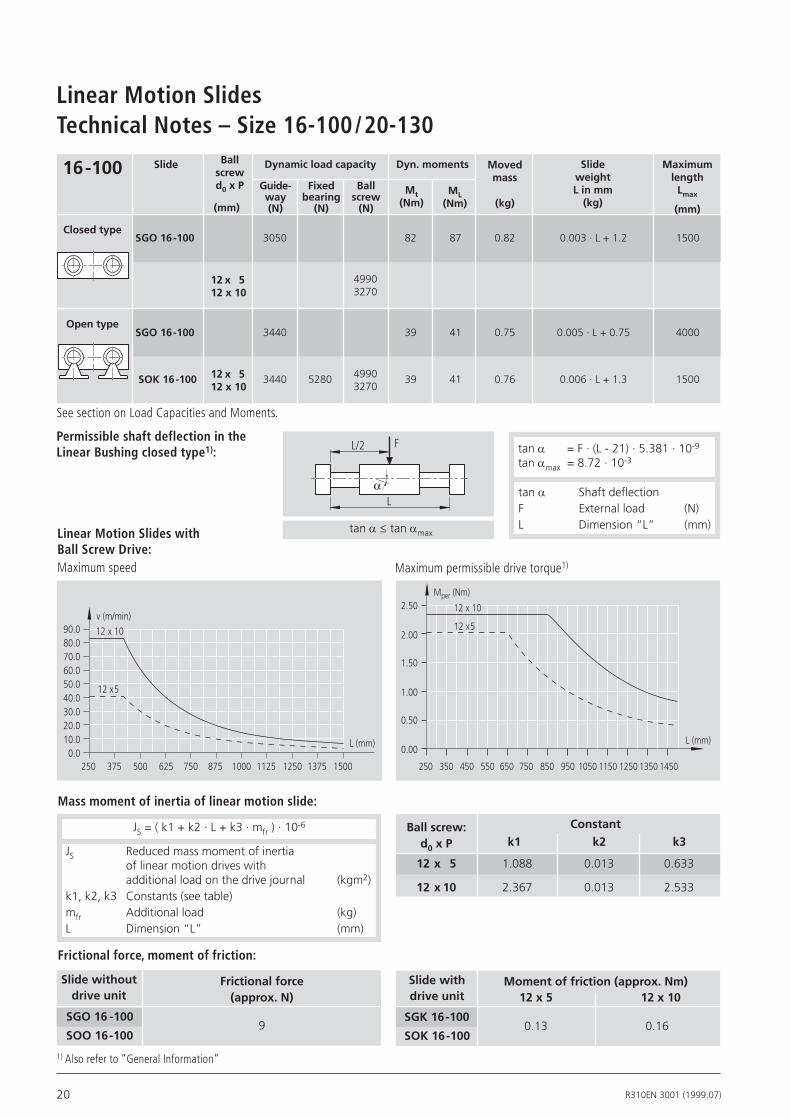
Linear Motion SlidesTechnical Notes – Size 16-100/20-130
Linear Motion Slides with Ball Screw Drive:Maximum speed
tan α Shaft deflectionF External load (N)L Dimension “L” (mm)
tan α = F · (L - 21) · 5.381 · 10-9
tan αmax = 8.72 · 10-3
Mass moment of inertia of linear motion slide:
Frictional force, moment of friction:
Maximum permissible drive torque1)
Frictionalforce(approx.N)
SOO16-100
SGO16-1009
Momentoffriction(approx.Nm)12x5
SOK16-100
SGK16-1000.13
250 375 500 625 750 875 1000 1125 1250 1375 15000.0
10.020.030.040.050.060.0
v (m/min)
L (mm)
12 x 5
12 x 1080.070.0
90.0
250 350 450 550 650 850 950 1050 1150 1250
0.00
0.50
1.00
1.50
2.00
2.50
L (mm)
Mper (Nm)
750 1350 1450
12 x 5
12 x 10
tan α ≤ tan αmax
1) Also refer to “General Information”
See section on Load Capacities and Moments.
12x10
0.16
0.633
2.533
Ballscrew:d0xP k2
1.088
2.367
k1
12x 5
12x10
k3
0.013
0.013
Constant
Slidewithdriveunit
Slidewithoutdriveunit
JS = ( k1 + k2 · L + k3 · mfr ) · 10-6
JS Reduced mass moment of inertia of linear motion drives with additional load on the drive journal (kgm2)k1, k2, k3 Constants (see table)mfr Additional load (kg)L Dimension “L” (mm)
L/2
L
F
α
16-100 Slide
Closedtype
Opentype
Ballscrewd0xP
(mm)
Dynamicloadcapacity Dyn.moments
Mt(Nm)
ML(Nm)
SlideweightLinmm(kg)
MaximumlengthLmax
(mm)
SGO16-100 3050 82 87 0.82 0.003 · L + 1.2 1500
SOK16-100 3440 5280 39 41 0.76 0.006 · L + 1.3 150049903270
12x 512x10
49903270
12x 512x10
SGO16-100 3440 39 41 0.75 0.005 · L + 0.75 4000
Permissible shaft deflection in the Linear Bushing closed type1):
Guide-way(N)
Fixedbearing(N)
Ballscrew(N)
Movedmass
(kg)

21R310EN 3001 (1999.07)
20-130 Slide
Closedtype
Opentype
Ballscrewd0xP(mm)
Dynamicloadcapacity
Dyn.moments
Mt(Nm)
ML(Nm)
Movedmass
(kg)
SlideweightLinmm(kg)
MaximumlengthLmax
(mm)
Permissible shaft deflection in the Linear Bushing closed type1): tan α = F · (L - 36) · 2.932 · 10-9
tan αmax = 8.72 · 10-3
SOO20-130 6100 134 141 1.6 0.008 · L + 1.6 4000
SOK20-130 16x10 6100 13400 9600 134 141 1.6 0.010 · L + 2.7 2500
SGK20-130 16x10 6040 13400 9600 217 229 1.8 0.006 · L + 3.0 2500
16x16 6200
16x 5 12300
16x16 6200
16x 5 12300
L/2
L
F
α tan α Shaft deflectionF External load (N)L Dimension “L” (mm)tan α ≤ tan αmax
Maximum permissible drive torque1)
Ball screw drive with keyway: maximum drive torque 3.2 Nm
Linear Motion Slides with Ball Screw Drive:Maximum speed
2500.0
L (mm)
500 750 1000 1250 1500 1750 2000 2250 2500
10.0
20.0
30.0
40.0
50.0
60.0
70.0
80.0v (m/min)
16 x 16
16 x 10
16 x 5
2500.00
L (mm)
500 750 1000 1250 1500 1750 2000 2250 2500
0.50
1.00
1.50
2.00
2.50
3.00
3.50
4.00 16 x 16
16 x 10
16 x 5
Mper (Nm)
See section on Load Capacities and Moments.
SGO20-130 6040 217 229 1.8 0.005 · L + 2.6 2500
JS = ( k1 + k2 · L + k3 · mfr ) · 10-6
SOO20-130
SGO20-130
Frictionalforce(approx.N)
11
Momentoffriction(approx.Nm)
SGK20-130
SOK20-130
Frictional force, moment of friction:
JS Reduced mass moment of inertia of linear motion slide with additional load on the drive journal (kgm2)k1, k2, k3 Constants (see table)mfr Additional load (kg)L Dimension “L” (mm)
16x5 16x10 16x16
0.40 0.43 0.46
Mass moment of inertia of linear motion slide:
1) Also refer to “General Information”
Slidewithdriveunit
Slidewithoutdriveunit
Ballscrew:d0xP k2k1 k3
Constant
16x 5
16x10
16x16
3.238
6.692
13.878
0.039
0.039
0.039
0.633
2.533
6.485
Technical Notes – Size 16-100/20-130
Guide-way(N)
Fixedbearing(N)
Ballscrew(N)
22 R310EN 3001 (1999.07)
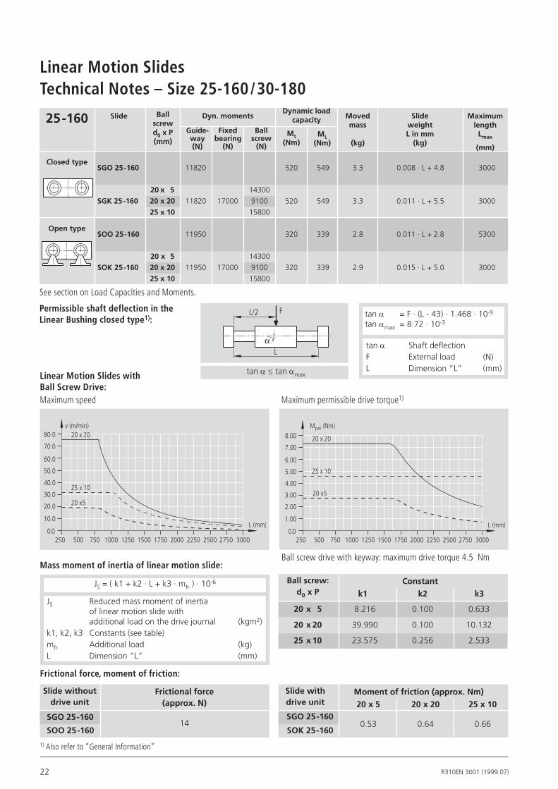
Linear Motion SlidesTechnical Notes – Size 25-160/30-180
L/2
L
F
α
tan α ≤ tan αmax
Ball screw drive with keyway: maximum drive torque 4.5 Nm
25-160 Slide
Closedtype
Opentype
Ballscrewd0xP(mm)
DynamicloadcapacityDyn.moments
Mt(Nm)
ML(Nm)
Movedmass
(kg)
SlideweightLinmm(kg)
MaximumlengthLmax
(mm)
SGO25-160 11820 520 549 3.3 0.008 · L + 4.8 3000
Permissible shaft deflection in the Linear Bushing closed type1):
tan α = F · (L - 43) · 1.468 · 10-9
tan αmax = 8.72 · 10-3
SOO25-160 11950 320 339 2.8 0.011 · L + 2.8 5300
SOK25-160 20x20 11950 17000 9100 320 339 2.9 0.015 · L + 5.0 3000
SGK25-160 20x20 11820 17000 9100 520 549 3.3 0.011 · L + 5.5 3000
25x10 15800
20x 5 14300
25x10 15800
20x5 14300
Linear Motion Slides with Ball Screw Drive:Maximum speed
tan α Shaft deflectionF External load (N)L Dimension “L” (mm)
2500.0
L (mm)
500 750 1000 1250 1500 1750 2000 2250 2500
10.0
20.0
30.0
40.0
50.0
60.0
70.0
80.0v (m/min)
2750 3000
20 x 20
25 x 10
20 x 5
2500.0
L (mm)
500 750 1000 1250 1500 1750 2000 2250 2500
1.00
2.00
3.00
4.00
5.00
6.00
7.00
8.00
2750 3000
20 x 20
25 x 10
20 x 5
Mper (Nm)
Maximum permissible drive torque1)
See section on Load Capacities and Moments.
JS = ( k1 + k2 · L + k3 · mfr ) · 10-6
SOO25-160
SGO25-160
Frictionalforce(approx.N)
14
Momentoffriction(approx.Nm)
SGO25-160
SOK25-160
Frictional force, moment of friction:
JS Reduced mass moment of inertia of linear motion slide with additional load on the drive journal (kgm2)k1, k2, k3 Constants (see table)mfr Additional load (kg)L Dimension “L” (mm)
20x5 20x20 25x10
0.53 0.64 0.66
Mass moment of inertia of linear motion slide:
1) Also refer to “General Information”
Slidewithdriveunit
Slidewithoutdriveunit
Ballscrew:d0xP k2k1 k3
Constant
20x 5
20x20
25x10
8.216
39.990
23.575
0.100
0.100
0.256
0.633
10.132
2.533
Guide-way(N)
Fixedbearing(N)
Ballscrew(N)

23R310EN 3001 (1999.07)
L/2
L
F
α
tan α ≤ tan αmax
Ball screw drive with keyway: maximum drive torque 4.5 Nm
30-180 Slide
Closedtype
Opentype
Ballscrewd0xP(mm)
Dynamicloadcapacity
Dyn.moments
Mt(Nm)
ML(Nm)
Movedmass
(kg)
SlideweightLinmm(kg)
MaximumlenghtLmax
(mm)
Permissible shaft deflection in the Linear Bushing closed type1):
SOO30-180 14520 425 447 4.1 0.016 · L + 4,1 5300
SOK30-180 20x20 14520 17000 9100 425 447 4.2 0.020 · L + 6,8 3000
SGK30-180 20x20 14360 17000 9100 689 725 4.6 0.014 · L + 7,4 3000
25x10 15800
20x 5 14300
Linear Motion Slides with Ball Screw Drive:Maximum speed
SGO30-180 14360 689 725 4.7 0.011 · L + 6,7 3000
tan α Shaft deflectionF External load (N)L Dimension “L” (mm)
Maximum permissible drive torque1)
2500.0
L (mm)
500 750 1000 1250 1500 1750 2000 2250 2500
10.0
20.0
30.0
40.0
50.0
60.0
70.0
80.0v (m/min)
2750 3000
20 x 20
25 x 10
20 x 5
2500.0
L (mm)
500 750 1000 1250 1500 1750 2000 2250 2500
1.00
2.00
3.00
4.00
5.00
6.00
7.00
8.00
2750 3000
20 x 20
25 x 10
20 x 5
Mper (Nm)
tan α = F · (L - 51) · 7.698 · 10-10
tan αmax = 8.72 · 10-3
See section on Load Capacities and Moments.
20x 5 14300
25x10 15800
1) Also refer to “General Information”
JS = ( k1 + k2 · L + k3 · mfr ) · 10-6
SOO30 -180
SGO30 -180
Frictionalforce(approx.N)
18
Momentoffriction(approx.Nm)
SGO30 -180
SOK30 -180
Frictional force, moment of friction:
JS Reduced mass moment of inertia of linear motion drives with additional load on the drive journal (kgm2)k1, k2, k3 Constants (see table)mfr Additional load (kg)L Dimension “L” (mm)
20x5 20x20 25x10
0.53 0.64 0.66
Mass moment of inertia of linear motion slide:
Slidewithdriveunit
Slidewithoutdriveunit
Ballscrew:d0xP k2k1 k3
Constant
20x 5
20x20
25x10
9.103
54.169
27.12
0.100
0.100
0.256
0.633
10.132
2.533
Guide-way(N)
Fixedbearing(N)
Ballscrew(N)

24 R310EN 3001 (1999.07)
L/2
L
F
α
tanα ≤ tanαmax
Ball screw drive with keyway: maximum drive torque 18 Nm
40-230 Slide
Closedtype
Opentype
Ballscrewd0xP(mm)
Dynamicloadcapacity
Dyn.moments
Mt(Nm)
ML(Nm)
Movedmass
(kg)
SlideweightLinmm(kg)
MaximumlengthLmax
(mm)
Linear Motion Slides with Ball Screw Drive:
SGO40-230 24660 1504 1713 9.4 0.020 · L + 13.3 4000
32x10 26200 32x5 21500
Permissible shaft deflection in the Linear Bushing closed type1):
Maximum speed
tan α = F · (L - 79) · 3.407 · 10-10
tan αmax = 8.72 · 10-3
tan α Shaft deflectionF External load (N)L Dimension “L” (mm)
Maximum permissible drive torque1)
32x5 21500
SOO40-230 24950 928 1057 8.3 0.026 · L + 8.3 5300
0.0L (mm)
500 1000 1500 2000 2500
10.0
20.0
30.0
40.0
50.0
60.0
70.0
80.0
v (m/min)
3000 3500 4000
32 x 32
32 x 20
32 x 10
32 x 5
0.0L (mm)
500 1000 1500 2000 2500
5.0
10.0
15.0
20.0
25.0
30.0
35.0
40.0
Mper (Nm)
3000 3500 4000
32 x 32
32 x 20
32 x 10
32 x 5
See section on Load Capacities and Moments. 32x32 17800
SOK40-230 24950 26000 928 1057 8.5 0.032 · L + 13.2 4000 32x20 17900
32x32 17800
32x10 26200
32x20 17900SGK40-230 24660 26000 1504 1713 9.3 0.025 · L + 14.2 4000
1) Also refer to “General Information”
JS = ( k1 + k2 · L + k3 · mfr ) · 10-6
SOO40 -230
SGO40 -230
Frictionalforce(approx.N)
22
Momentoffriction(approx.Nm)
SGO40 -230
SOK40-230
Frictional force, moment of friction:
JS Reduced mass moment of inertia of linear motion slide with additional load on the drive journal (kgm2)k1, k2, k3 Constants (see table)mfr Additional load (kg)L Dimension “L” (mm)
Mass moment of inertia of linear motion slide:
Slidewithdriveunit
Slidewithoutdriveunit
Ballscrew:d0xP k2k1 k3
Constant
32x 5
32x10
32x20
32x32
51.8 53
69.446
138.21
268.83
0.712
0.712
0.667
0.667
0.633
2.535
10.132
25.938
32x5 32x10 32x20 32x32
1.14 1.24 1.23 1.27
Linear Motion SlidesTechnical Notes – Size 40-230 / 50-280
Guide-way(N)
Fixedbearing(N)
Ballscrew(N)

25R310EN 3001 (1999.07)
L/2
L
F
α
tan α ≤ tan αmax
50-280 Slide
Closedtype
Opentype
BallscrewdoxP(mm)
Dynamicloadcapacity
Dyn.moments
Mt(Nm)
ML(Nm)
Movedmass
(kg)
SlideweightLinmm(kg)
MaximumlengthLmax
(mm)
Linear Motion Slides with Ball Screw Drive:
SGO50-280 36060 2740 3011 16.4 0.031 · L + 22.1 4000
Permissible shaft deflection in the Linear Bushing closed type1):
Maximum speed
tan α = F · (L - 107) · 1.649 · 10-10
tan αmax = 8.72 · 10-3
tan α Shaft deflectionF External load (N)L Dimension “L” (mm)
Maximum permissible drive torque1)
32x32 17800
32x32 17800
SOO50-280 36380 1687 1853 14.8 0.039 · L + 14.8 5300
0.0L (mm)
500 1000 1500 2000 2500
10.0
20.0
30.0
40.0
50.0
60.0
70.0
80.0
v (m/min)
3000 3500 4000
32 x 32
32 x 20
32 x 10
32 x 5
0.0L (mm)
500 1000 1500 2000 2500
5.0
10.0
15.0
20.0
25.0
30.0
35.0
40.0
Mper (Nm)
3000 3500 4000
32 x 32
32 x 20
32 x 10
32 x 5
Ball screw drive with keyway: maximum drive torque 18 Nm
1) Also refer to “General Information”
See section on Load Capacities and Moments.
32x10 26200
32x10 26200
32x20 17900SGK50-280 36060 26000 2740 3011 16.0 0.036 · L + 22.8 4000
32x20 17900 SOK50-280 36380 26000 1687 1853 14.8 0.046 · L + 21.3 4000
32x5 21500
32x5 21500
JS = ( k1 + k2 · L + k3 · mfr ) · 10-6
SOO50 -280
SGO50 -280
Frictionalforce(approx.N)
27
Momentoffriction(approx.Nm)
SGO50 -280
SOK50-280
Frictional force, moment of friction:
JS Reduced mass moment of inertia of linear motion slide with additional load on the drive journal (kgm2)k1, k2, k3 Constants (see table)mfr Additional load (kg)L Dimension “L” (mm)
Mass moment of inertia of linear motion slide:
Slidewithdriveunit
Slidewithoutdriveunit
Ballscrew:d0xP k2k1 k3
Constant
32x 5
32x10
32x20
32x32
56.025
87.214
209.28
468.78
0.712
0.712
0.667
0.667
0.633
2.533
10.132
25.938
1.14 1.25 1.25 1.30
32x5 32x10 32x20 32x32
Guide-way(N)
Fixedbearing(N)
Ballscrew(N)
26 R310EN 3001 (1999.07)
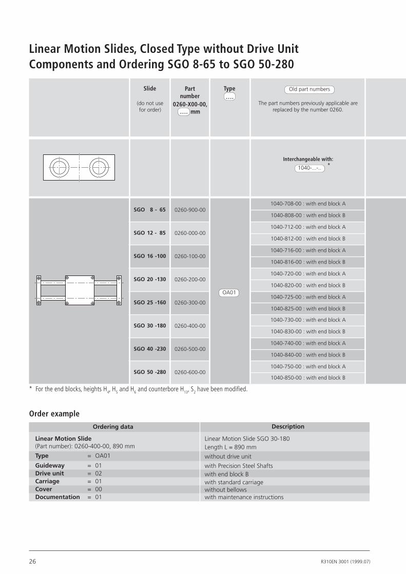
Components and Ordering SGO 8-65 to SGO 50-280
* For the end blocks, heights H4, H5 and H6 and counterbore H13, S2 have been modified.
Linear Motion Slides, Closed Type without Drive Unit
Orderingdata
Order exampleDescription
LinearMotionSlide(Part number): 0260-400-00, 890 mm
Type = OA01
Guideway = 01Driveunit = 02Carriage = 01Cover = 00Documentation = 01
Linear Motion Slide SGO 30-180Length L = 890 mm
without drive unit
with Precision Steel Shaftswith end block Bwith standard carriagewithout bellowswith maintenance instructions
Slide
(do not use for order)
SGO 8- 65
SGO12- 85
SGO16-100
SGO20-130
SGO25-160
SGO30-180
SGO40-230
SGO50-280
Old part numbers
The part numbers previously applicable are replaced by the number 0260.
Interchangeable with:
1040-...-..
1040-708-00 : with end block A
1040-808-00 : with end block B
1040-712-00 : with end block A
1040-812-00 : with end block B
1040-716-00 : with end block A
1040-816-00 : with end block B
1040-720-00 : with end block A
1040-820-00 : with end block B
1040-725-00 : with end block A
1040-825-00 : with end block B
1040-730-00 : with end block A
1040-830-00 : with end block B
1040-740-00 : with end block A
1040-840-00 : with end block B
1040-750-00 : with end block A
1040-850-00 : with end block B
Part number
0260-900-00
0260-000-00
0260-100-00
0260-200-00
0260-300-00
0260-400-00
0260-500-00
0260-600-00
OA01
0260-X00-00, …. mm
*
Type….

27R310EN 3001 (1999.07)
Guideway ..
End block A End block B
01 02 01 00 01 01
Carriage ..
Drive unit ..
(end block)
without with
Polyurethanebellows
StandardStandard shafts
Maintenanceinstructions
Steel shaftswith STAR-
Resist coating
Shafts of corrosion resistant steel to
DIN 17230 / EN 10088
Documentation ..
Cover ..
01 02 03
28 R310EN 3001 (1999.07)
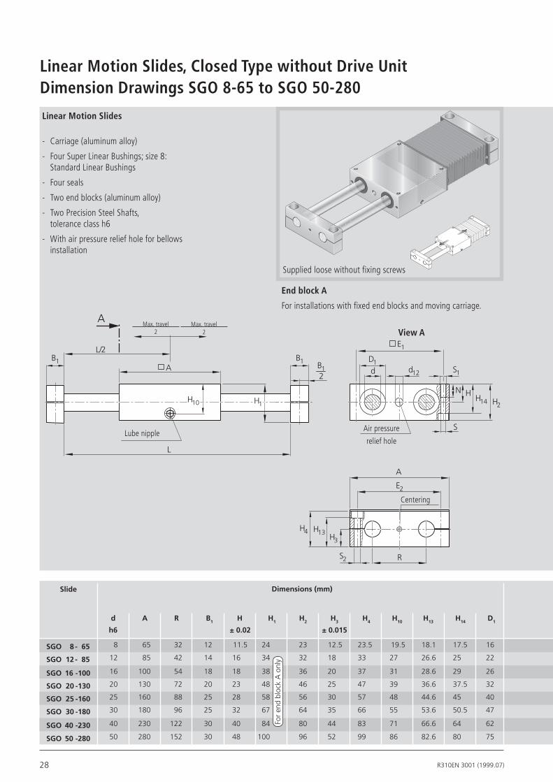
Dimension Drawings SGO 8-65 to SGO 50-280Linear Motion Slides, Closed Type without Drive Unit
Slide
d A R B1 H H1 H2 H3 H4 H10 H13 H14 D1
h6 ±0.02 ±0.015
Linear Motion Slides
- Carriage (aluminum alloy)
- Four Super Linear Bushings; size 8: Standard Linear Bushings
- Four seals
- Two end blocks (aluminum alloy)
- Two Precision Steel Shafts, tolerance class h6
- With air pressure relief hole for bellows installation
End block A
For installations with fixed end blocks and moving carriage.
Supplied loose without fixing screws
View A
Dimensions(mm)
8 65 32 12 11.5 24 23 12.5 23.5 19.5 18.1 17.5 16
12 85 42 14 16 34 32 18 33 27 26.6 25 22
16 100 54 18 18 38 36 20 37 31 28.6 29 26
20 130 72 20 23 48 46 25 47 39 36.6 37.5 32
25 160 88 25 28 58 56 30 57 48 44.6 45 40
30 180 96 25 32 67 64 35 66 55 53.6 50.5 47
40 230 122 30 40 84 80 44 83 71 66.6 64 62
50 280 152 30 48 100 96 52 99 86 82.6 80 75
Centering
For
end
bloc
k A
onl
y
Air pressure
relief holeLube nipple
Max. travel2
SGO 8- 65
SGO 12- 85
SGO16-100
SGO20-130
SGO25-160
SGO30-180
SGO40-230
SGO50-280
B1 B12
B1
A
L/2
A
H10
L
H1
d12
D1d S1
N HH14 H2
S
E1
S2 R
E2
H3
H13H4
A
Max. travel2

29R310EN 3001 (1999.07)
Supplied loose with fixing screws
Max. travel2
Max. travel2 View A
End block B
For installations with fixed carriage and moving end blocks.
Centering
Air pressure
relief holeLube nipples
Screw S6 - DIN 912
B1B12
B1
A
A
L/2
L
R
E2
H5
H6
A
d12
D1
d S1
N H H14 H2
S
E1
H10
55 52 4.3 M 5 5.5 11 M 5 x 15 11 22 D 4 8 L = travelmax x 1.4 + 99
73 70 5.3 M 6 6.6 13 M 6 x 22 15 30 AM 6 10 L = travelmax x 1.33 + 122
88 82 5.3 M 6 9.0 13 M 8 x 25 17 34 AM 6 12 L = travelmax x 1.33 + 137
115 108 6.6 M 8 11.0 18 M 10 x 30 22 44 AM 6 14 L = travelmax x 1.30 + 168
140 132 8.4 M 10 13.0 22 M 12 x 40 27 54 AM 8 x 1 16 L = travelmax x 1.24 + 199
158 150 10.5 M 12 13.0 26 M 12 x 45 31 62 AM 8 x 1 20 L = travelmax x 1.20 + 218
202 190 13.5 M 16 17.0 34 M 16 x 60 39 78 AM 8 x 1 22 L = travelmax x 1.17 + 273
250 240 13.5 M 16 17.0 34 M 16 x 60 47 94 AM 8 x 1 25 L = travelmax x 1.14 + 323
LengthcalculationAirpressurereliefhole
EndblockB Lubenipple Forbellowsinstallation
E1 E2 S S1 S2 N S6 H5 H6 DIN3405 d12

30 R310EN 3001 (1999.07)
Determining the switch activa-tion pointThe switch activation point is to be taken from the data given on mounting side, travel direction and switching distance (see table above and order example).
Mounting side: The switches can be fitted on the left (L) or right (R) side of the slide.
Travel direction: The switches can be fitted on the minus (–) or plus (+) side of zero.
Switching distance: The switching distance is the distance between the carriage center (TM) and the zero point (0) when a switch is operated (given in mm).
See “Switch Installation” for more details on fitting switches, types of switch and fitting the cable duct.
- Travel direction +
right (R)
left (L) 0 L/2
L
TM
Components and Ordering SGK 12-85 to SGK 20-130Linear Motion Slides, Closed Type with Ball Screw Drive
Slide
Ball screw
Drive unit..
JournalStandardshafts
8x2.5
12x5
16x5
16x10
16x16
SGK12- 85
SGK16 -100
SGK20-130
0261-000-00
0261-100-00
0261-200-00
dia. 6
dia. 6
dia. 9
dia. 9 with keyway
SGK12- 85
SGK16-100
SGK20-130
0261-000-00
0261-100-00
0261-200-00
dia. 6
dia. 6
dia. 9
01
01
01
01
01
01
Part number Guideway ..
Type ….0261-X00-00,
…. mm
OF01
12x10
01
01 02
01 02 03
04 05 06
01
01 02
01 02 03
MF01
Order example: see Inquiry/Order FormCan be supplied with end block B on request.

31R310EN 3001 (1999.07)
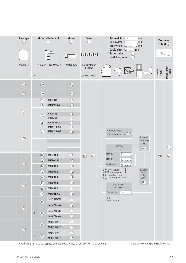
1) Observe maximum permissible torque. * Attachment can also be supplied without motor. Please enter “00” for motor on order.
Standard Motor Type
i =
Motor attachment..
Motor..
without with
Cover..
without switch
Stan
dard
repo
rt
Mea
sure
men
tre
port
PNP NO
PNP NC 11 -. ±....
Externalswitching
cam
Externalsocket-
plug(loose)
17
Externalswitch
TypeLength in mm
Cable duct(loose)
01 03
01
01
01
00
00
00
01
01
01
01
1
1
1
1
00
16
13 -. ±....
Mechanical 15 -. ±....
Cable duct 20 - X....
02
00
00
00
for Motor1)*Mount
MMD022A
VRDM368
MMD022A
VRDM368
Carriage..
Documen-tation ..
Polyurethanebellows
Mounting side
Switching distanceTravel direction
Switc
h ac
ti-va
tion
poin
t
without cable duct 00
Switch type
58
27
03
02
03
02
58
27
1st switch .. - . ± ….. mm 2nd switch .. - . ± ….. mm 3rd switch .. - . ± ….. mm Cable duct .. - . .... mm Socket-plug .. Switching cam ..
MKD25B
MKD41B
MMD042A
MMD082A
VRDM397
VRDM3910
50
10
59
60
28
29
02
01
05
06
03
03

32 R310EN 3001 (1999.07)
L/2
B15
ød1
H15H10
S15
B4B5
E4E2A
L1
L2
E1
A
A
B1 B12
L
H1
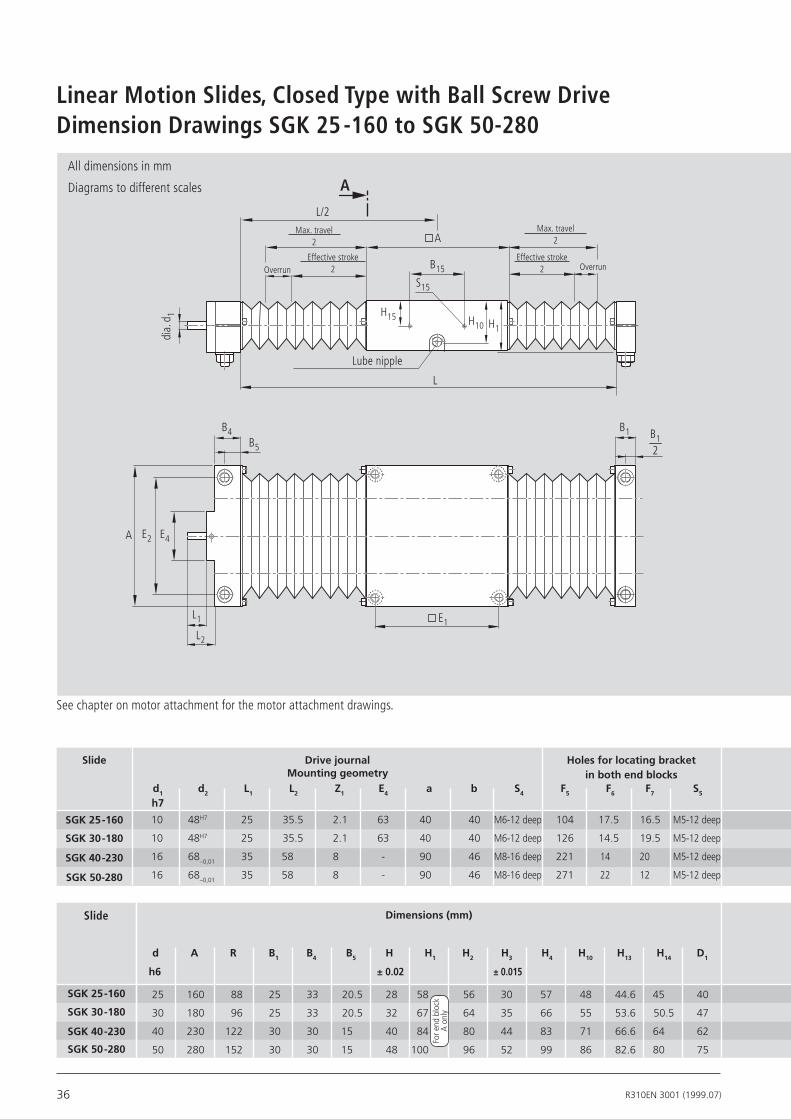
Linear Motion Slides, Closed Type with Ball Screw DriveDimension Drawings SGK 12-85 to SGK 20-130
Slide Dimensions(mm)
d A R B1 B4 B5 H H1 H2 H3 H4 H10 H13 H14 D1
h6 ±0.02 ±0.015
12 85 42 14 24 17 16 34 32 18 33 27 26.6 25 22
16 100 54 18 24 15 18 38 36 20 37 31 28.6 29 26
20 130 72 20 29 19 23 48 46 25 47 39 36.6 37.5 32
SGK12- 85
SGK16-100
SGK20 -130
Slide DrivejournalMountinggeometry
6 28 18 25 2.1 40 33 23 M4 - 8 deep 53 9.5 11.5 M4-8 deep
6 28 18 25 2.1 40 33 23 M4 - 8 deep 60 11 14 M4-8 deep
9 40 25 34.5 2.1 52 40 28 M6-12 deep 74 15.5 18.5 M5-12 deep
d1 d2 L1 L2 Z1 E4 a b S4 F5 F6 F7 S5 h7 H7
Holesforlocatingbracketinbothendblocks
For e
nd b
lock
A
onl
y
See chapter on motor attachment for the motor attachment drawings.
Max. travel2
Max. travel2
Effective stroke2
Effective stroke2
Lube nipple
SGK12- 85
SGK16-100
SGK20-130
Overrun Overrun
All dimensions in mm
Diagrams to different scales

33R310EN 3001 (1999.07)
B15 H15 S15 F12 H12 d12
Forswitchingcam Airpressurereliefholes
30 13.5 M4-7 deep 16 10.4 6.8 L = travel max x 1.33 + 122
30 13 M4-7 deep 24.4 12 8.5 L = travel max x 1.33 + 137
64 23 M4-8 deep 37 15.5 10 L = travel max x 1.30 + 168
LengthcalculationForbellowsinstallation
TB02-016-01
TB02-016-02
TB02-016-03
LubenippleWithendblockB
E1 E2 S S1 S2 S8 N S6 H5 H6 DIN3405
73 70 5.3 M 6 6.6 M 6 x 35 13 M 6 x 22 15 30 AM 6
88 82 5.3 M 6 9 M 8 x 40 13 M 8 x 25 17 34 AM 6
115 108 6.6 M 8 11 M 10 x 55 18 M 10 x 30 22 44 AM 6
Centering depth Z1
(internal centering)
Schraube S6 - DIN912
View A
Air pressure relief hole
Screw S8 - DIN912
Version with end block B available on request
BallscrewjournalwithkeywayForsizeSGK20-130
Formodificationstothecarriage,pleaseaskforoneofthefollowing
drawingsonCD
h=1.8
202.5
3P9
H5
H6
F5a
d2
S5 S4
bH4 F7
F6
H3H13
R
S2
H12
dd12 S1
F12 S
D1
H2H14
HN
Z X
Y
Z X
Y
ServomotorsMKD
MiniDriveMMD
SteppingmotorsVRDM
SGK MKD X Y Z 20-130 25 B 233 54 75 41 B 243 82 77.5
SGK MMD X Y Z 12-85 022A 128 60 5016-100
20-130 042A 157 60 72
082A 178 80 83Z X
Y
SGK VRDM X Y Z 12-85 368 116 57.2 50 16-100 20-130 397 110 85 77.5
3910 140

34 R310EN 3001 (1999.07)
Linear Motion Slides, Closed Type with Ball Screw DriveComponents and Ordering SGK 25-160 to SGK 50-280
20x5
20x20
25x10
32x5
32x10
32x20
dia. 10
dia. 16
dia. 10
dia. 10 with keyway
dia. 16dia. 16 with
keyway
01
01
01 02 04
01 02 03 04
dia. 10
dia. 10
dia. 16
dia. 16
01
01
RV01
RV02
RV031)
RV041)
32 x
32
02.36.1102.36.1202.56.1002.56.11
01 02 04
05 06 08
01 02 03 04
05 06 07 08
OF01
0261-300-00
0261-400-00
0261-500-00
0261-600-00
SGK25-160
SGK30-180
SGK40-230
SGK50-280
SGK25-160
SGK30-180
SGK40-230
SGK50-280
0261-300-00
0261-400-00
0261-500-00
0261-600-00
0261-300-00
0261-400-00
0261-500-00
0261-600-00
SGK25-160
SGK30-180
SGK40-230
SGK50-280
RV01
RV02
02.36.21
RV03
RV04
02.36.20
RV01
RV02
02.56.21
RV03
RV04
02.56.20
01
01
01
01
11 12 14
11 12 14
01 02 03 04
01 02 03 04
Can be supplied with end block B on request.
MF01
Order example: see Inquiry/Order FormTo determine switch activation point see section “Components and Ordering”, e.g. for type SGO. 1) Switch can only be mounted on the side opposite the side drive.
Slide Drive unit..
Part number Guideway ..
Type ….0261-X00-00,
…. mm
Ball screwJournalStandardshafts

35R310EN 3001 (1999.07)
1) Observe maximum permissible torque.
Stan
dard
repo
rt
Mea
sure
men
tre
port
00
00
01
01
i =
01
01
without switch
without cable duct
PNP NO
PNP NC 11 -. ±....
Externalswirtching
cam
External socket-
plug (loose)
17
Externalswitch
TypeLength in mm
Cable duct (loose)
00
16
13 -. ±....
Mechanical 15 -. ±....
Cable duct 20 - X....
* Attachment can also be supplied without motor. Please enter “00” for motor on order.
MKD71B-061
MKD71B-097
VRDM397
VRDM3910
VRDM3913
MKD41B
MMD082A
01
04
06
01 030100
02
11
12
Switch typeMounting side
Switching distanceTravel direction
Switc
h ac
ti-va
tion
poin
t
MKD41B
MMD082A
10
MKD41B
MMD082A
10
1
1.5
10
10
1
1.5
10
12
14
16
MKD71B-061
MKD71B-097
MKD71B-061
MKD71B-097
MKD71B-061
MKD71B-097
MKD71B-061
MKD71B-097
11
12
11
12
11
12
11
12
1
2
1
2
01
01
01
01
10
20 60
12
22 60
14
24
16
MKD41B
MMD082A
MKD41B
MMD082A
60
26 60
00
00
03 10
60
28
29
3005
Motor attachment..
Motor..
Cover..
Carriage..
1st switch .. - . ± ….. mm 2nd switch .. - . ± ….. mm 3rd switch .. - . ± ….. mm Cable duct .. - . .... mm Socket-plug .. Switching cam ..
Documen-tation ..
Standard Motor Type
without with
for Motor1)*Mount Polyurethanebellows
36 R310EN 3001 (1999.07)
L
B1 B12
L/2
A
B15
A
S15
H15 H10
dia.
d1
B4B5
E4E2A
L1
L2
E1
H1
d A R B1 B4 B5 H H1 H2 H3 H4 H10 H13 H14 D1
h6 ±0.02 ±0.015
Dimension Drawings SGK 25-160 to SGK 50-280Linear Motion Slides, Closed Type with Ball Screw Drive
Max. travel2
Max. travel2
Slide Dimensions(mm)
SGK25-160
SGK30-180
SGK40-230
SGK50-280
25 160 88 25 33 20.5 28 58 56 30 57 48 44.6 45 40
30 180 96 25 33 20.5 32 67 64 35 66 55 53.6 50.5 47
40 230 122 30 30 15 40 84 80 44 83 71 66.6 64 62
50 280 152 30 30 15 48 100 96 52 99 86 82.6 80 75
SGK25-160
SGK30-180
SGK40-230
SGK50-280
Slide DrivejournalMountinggeometry
10 48H7 25 35.5 2.1 63 40 40 M6-12 deep 104 17.5 16.5 M5-12 deep
10 48H7 25 35.5 2.1 63 40 40 M6-12 deep 126 14.5 19.5 M5-12 deep
16 68– 0,01 35 58 8 - 90 46 M8-16 deep 221 14 20 M5-12 deep
16 68–0,01 35 58 8 - 90 46 M8-16 deep 271 22 12 M5-12 deep
d1 d2 L1 L2 Z1 E4 a b S4 F5 F6 F7 S5 h7
See chapter on motor attachment for the motor attachment drawings.
Lube nipple
Effective stroke2
Effective stroke2
Holesforlocatingbracketinbothendblocks
Overrun Overrun
All dimensions in mm
Diagrams to different scales
For e
nd b
lock
A
onl
y

37R310EN 3001 (1999.07)
LubenippleWithendblockB
E1 E2 S S1 S2 S8 N S6 H5 H6 DIN3405
B15 H15 S15 F12 H12 d12
Forswitchingcam Airpressurereliefholes
64 26 M4-10deep 40 18.5 12.5 L = travel max x 1.24 + 199
64 33 M4-10deep 40 21 15 L = travel max x 1.20 + 218
64 21 M4-10deep 54 28 18 L = travel max x 1.17 + 273
64 21 M4-10deep 60 30 22 L = travel max x 1.14 + 323
LengthcalculationForbellowsinstallation
140 132 8.4 M 10 13.0 M 12 x 60 22 M 12 x 40 27 54 AM 8 x 1
158 150 10.5 M 12 13.0 M 12 x 70 26 M 12 x 45 31 62 AM 8 x 1
202 190 13.5 M 16 17.0 M 16 x 90 34 M 16 x 60 39 78 AM 8 x 1
250 240 13.5 M 16 17.0 M 16 x 100 34 M 16 x 60 47 94 AM 8 x 1
Formodificationstothecarriage,pleaseaskforoneofthefollowing
drawingsonCD
TB02-016-04
TB02-016-05
TB02-016-06
TB02-016-07
KGT-Zapfen mit Paßfedernut
View A
Screw S6 - DIN 912
S2
S1
F12 S
N
d12
H5
H6
H2H14
HH12
d
D1
F5a
d2
H3
H13
R
bH4
F7
F6
S4S5
Centering depth Z1
(internal centering)
Screw S8 - DIN 912
h=1.8
202.5
3P9
h=3
284
5P9
L1
B4
dia
d 1
dia
d 2 H7Z1
L2
L1 Z1L2 B4
dia
d 1
dia
d 2-0
.01
Size
withkeyway withoutkeyway
withcenteringdepthZ1external
withcenteringdepthZ1internal
SGK25-160
SGK30-180
SGK40-230
SGK50-280
Ballscrewjournal
Version with end block Bavailable on request
Air pressure relief holes

38 R310EN 3001 (1999.07)
Components and Ordering SOO 12-85 to SOO 50-280Linear Motion Slides, Open Type without Drive Unit
Orderingdata
Order exampleDescription
LinearMotionSlide(Part number): 0265-400-00, 890 mm
Type = OA01
Guideway = 01Carriage = 01Cover = 00Documentation = 01
Linear Motion Slide SOO 30-180Length L = 890 mm
without drive unit
with Precision Steel Shaftswith standard carriagewithout bellowswith maintenance instructions
Old part numbers
The part numbers previously applicable are replaced by the number 02..
Interchangeable with:
1045-...-..
(do not use for order)
* The new carriages have a shoulder between the shaft supports (B6, H18).
SOO12- 85
SOO16-100
SOO20-130
SOO25-160
SOO30-180
SOO40-230
SOO50-280
0265-000-00
0265-100-00*
0265-200-00*
0265-300-00*
0265-400-00
0265-500-00
0265-600-00
1045-112-00
1045-116-00
1045-120-00
1045-125-00
1045-130-00
1045-140-00
1045-150-00
OA01
Slide Part number Type0265-X00-00,
…. mm

39R310EN 3001 (1999.07)
For open-type SOO Linear Motion Slides with bellows, end plates are scre-wed to both shaft ends (see dimension drawings).
00 01 01
without with
Polyurethane bellowsStandard Maintenanceinstructions
Guideway .. Carriage .. Cover .. Documentation ..
01 02 03 01
04 05 06
Standard shafts
Steel shafts with Resist coating
Shafts of corrosion resistant steel to
DIN 17230 / EN 10088
for bellows
40 R310EN 3001 (1999.07)
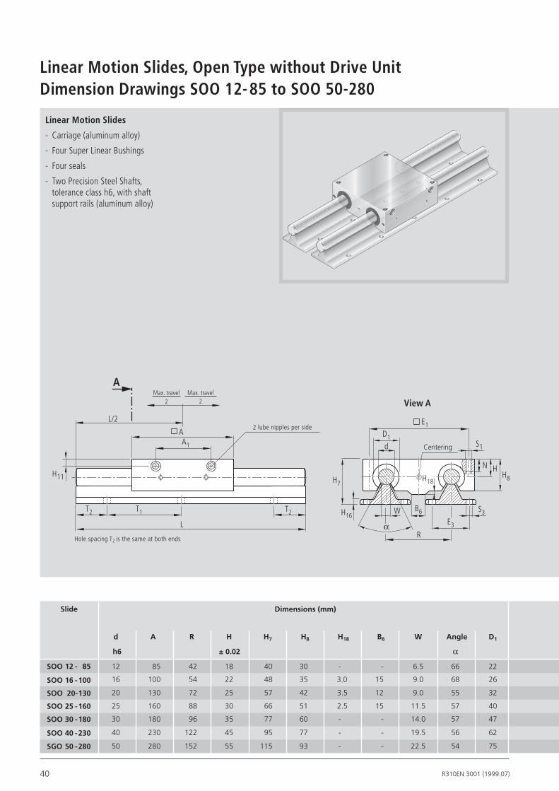
Dimension Drawings SOO 12-85 to SOO 50-280Linear Motion Slides, Open Type without Drive Unit
Linear Motion Slides
- Carriage (aluminum alloy)
- Four Super Linear Bushings
- Four seals
- Two Precision Steel Shafts, tolerance class h6, with shaft support rails (aluminum alloy)
Slide
d A R H H7 H8 H18 B6 W Angle D1
h6 ±0.02 α
Dimensions(mm)
12 85 42 18 40 30 - - 6.5 66 22
16 100 54 22 48 35 3.0 15 9.0 68 26
20 130 72 25 57 42 3.5 12 9.0 55 32
25 160 88 30 66 51 2.5 15 11.5 57 40
30 180 96 35 77 60 - - 14.0 57 47
40 230 122 45 95 77 - - 19.5 56 62
50 280 152 55 115 93 - - 22.5 54 75
View A
L/2
A
L
A1
T2T2 T1
H8HN
E1
R
D1
WE3
S3
α
H16
H11
B6
H7H18
S1d
AMax. travel
2Max. travel
2
Centering
Hole spacing T2 is the same at both ends
SOO12- 85
SOO16-100
SOO20-130
SOO25-160
SOO30-180
SOO40-230
SGO50-280
2 lube nipples per side

41R310EN 3001 (1999.07)
B6
R
H18
T2 T1 T2
L/2
A
H11
L
A1
d S1
E3
D1
H8HN
H17
H16
H7
E1
S3
A
d A R H H7 H8 H18 B6 W Angle D1
12 85 42 18 40 30 - - 6.5 66 22
16 100 54 22 48 35 3.0 15 9.0 68 26
20 130 72 25 57 42 3.5 12 9.0 55 32
25 160 88 30 66 51 2.5 15 11.5 57 40
30 180 96 35 77 60 - - 14.0 57 47
40 230 122 45 95 77 - - 19.5 56 62
50 280 152 55 115 93 - - 22.5 54 75
E1 S1 N H16 H17 S3 E3 T1 T2 A1 H11 DIN3405
73 M 6 13 5 6.5 4.5 29 75 min.15 57 7.0 AM 6 L = travel max x 1.33 + 122
88 M 6 13 5 8.3 5.5 33 100 min.20 68 7.2 AM 6 L = travel max x 1.33 + 137
115 M 8 18 6 9.8 6.6 37 100 min.20 94 7.2 AM 6 L = travel max x 1.30 + 168
140 M 10 22 6 9.8 6.6 42 120 min.24 116 9.5 AM 8 x 1 L = travel max x 1.24 + 199
158 M 12 26 7 10.0 9.0 51 150 min.30 130 9.5 AM 8 x 1 L = travel max x 1.20 + 218
202 M 16 34 8 11.8 9.0 55 200 min.30 170 11.5 AM 8 x 1 L = travel max x 1.14 + 269
250 M 16 34 9 14.3 11.0 63 200 min.30 220 15 .0 AM 8 x 1 L = travel max x 1.112 + 320
ForbellowsLubenippleShaftsupportrail
Version for bellows
LengthcalculationPlease inquire for length
L > 600 and L < 660 for sizes
SOO 40-230 and SOO 50-280
Hole spacing T2 is the same at both ends
Max. travel2
Max. travel2
Effective stroke2
Lube nipple
Centering
Counterbore for screws conforming to DIN 6912
Support rail supplied loose
View A3 mm
Effective stroke2 OverrunOverrun
All dimensions in mm
Diagrams to different scales

42 R310EN 3001 (1999.07)
Slide
Ball screwJournalStandard shafts
8x2.5
12x5
16x5
16x10
16x16
dia. 6
dia. 6
dia. 9
Can be supplied with end block B on request.
02
02
02
02
02
02
OF01
12x10
01
01 02
01 02 03
04 05 06
01
01 02
01 02 03
MF01
Order example: see Inquiry/Order Form
Components and Ordering SOK 12-85 SOK to 20-130Linear Motion Slides, Open Type without Drive Unit
SOK12- 85
SOK16-100
SOK20-130
SOK12- 85
SOK16-100
SOK20-130
0266-000-00
0266-100-00
0266-200-00
0266-000-00
0266-100-00
0266-200-00
Determining the switch activa-tion pointThe switch activation point is to be taken from the data given on mounting side, tra -vel direction and switching distance (see table above and order example).
Mounting side: The switches can be fitted on the left (L) or right (R) side of the slide.
Travel direction: The switches can be fitted on the minus (–) or plus (+) side of zero.
Switching distance: The switching distance is the distance between the carriage center (TM) and the zero point (0) when a switch is operated (given in mm).
See “Switch Installation” for more details on fitting switches, types of switch and fitting the cable duct.
- Travel direction +
right (R)
left (L) 0 L/2
L
TM
Drive unit..
Part number Guideway ..
Type ….0266-X00-00,
…. mm
dia. 6
dia. 6
dia. 9
dia. 9 with keyway

43R310EN 3001 (1999.07)
1) Observe maximum permissible torque. * Attachment can also be supplied without motor. Please enter “00” for motor on order.
i = without with
without switch
PNP NO
PNP NC 11 -. ±....
External switching
cam
External socket-
plug (loose)
17
Externalswitch
TypeLength in mm
Cable duct(loose)
01 03
01
01
01
00
00
00
01
01
01
01
1
1
1
1
00
16
13 -. ±....
Mechanical 15 -. ±....
Cable duct 20 - X....
02
00
00
00
MMD022A
VRDM368
MMD022A
VRDM368
Mounting side
Switching distanceTravel direction
Switc
h ac
ti-va
tion
poin
t
without cable duct 00
Switch type
58
27
03
02
03
02
58
27
MKD25B
MKD41B
MMD042A
MMD082A
VRDM397
VRDM3910
50
10
59
60
28
29
02
01
05
06
03
03
Motor attachment..
Motor..
Cover..
Carriage..
1st switch .. - . ± ….. mm 2nd switch .. - . ± ….. mm 3rd switch .. - . ± ….. mm Cable duct .. - . .... mm Socket-plug .. Switching cam ..
Documen-tation ..
Stan
dard
repo
rt
Mea
sure
men
tre
port
Standard Motor Typefor Motor1)*Mount Polyurethanebellows
44 R310EN 3001 (1999.07)
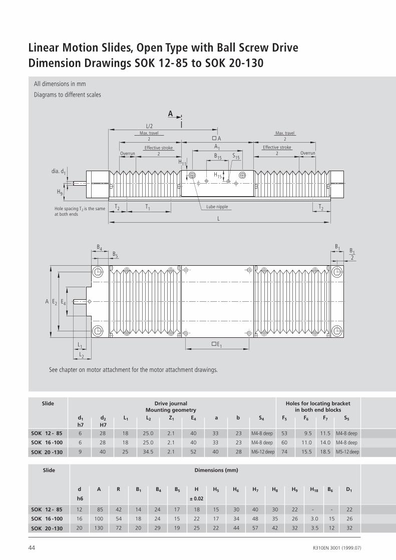
Dimension Drawings SOK 12-85 to SOK 20-130Linear Motion Slides, Open Type with Ball Screw Drive
Slide Dimensions(mm)
d A R B1 B4 B5 H H5 H6 H7 H8 H9 H18 B6 D1
12 85 42 14 24 17 18 15 30 40 30 22 - - 22
16 100 54 18 24 15 22 17 34 48 35 26 3.0 15 26
20 130 72 20 29 19 25 22 44 57 42 32 3.5 12 32
Slide DrivejournalMountinggeometry
6 28 18 25.0 2.1 40 33 23 M4-8 deep 53 9.5 11.5 M4-8 deep
6 28 18 25.0 2.1 40 33 23 M4-8 deep 60 11.0 14.0 M4-8 deep
9 40 25 34.5 2.1 52 40 28 M6-12deep 74 15.5 18.5 M5-12deep
d1 d2 L1 L2 Z1 E4 a b S4 F5 F6 F7 S5 h7 H7
B1
T2 T1 T2
L/2
B15 S15
A
A
dia. d1 H15
E4E2A
L1
L2
E1
L
B4B5
A1
H9
H11
B12
h6 ±0.02
Hole spacing T2 is the same at both ends
See chapter on motor attachment for the motor attachment drawings.
Lube nipple
Max. travel2
Max. travel2
Effective stroke2
Effective stroke2
SOK12- 85
SOK16-100
SOK20-130
SOK12- 85
SOK16-100
SOK20-130
Holesforlocatingbracketinbothendblocks
OverrunOverrun
All dimensions in mm
Diagrams to different scales

45R310EN 3001 (1999.07)
B15 H15 S15
Forswitchingcam
TB02-016-11
TB02-016-12
TB02-016-13
Lubenipple
E1 E2 S1 S6 N H16 H17 E3 S3 T1 T2 A1 H11 DIN3405
73 70 M 6 M 6 x 22 13 5 6.5 29 4.5 75 min.15 57 7 AM 6
88 82 M 6 M 8 x 25 13 5 8.3 33 5.5 100 min.20 68 7.2 AM 6
115 108 M 8 M10 x 30 18 6 9.8 37 6.6 100 min.20 94 7.2 AM 6
LengthcalculationForbellowsinstallation
30 13.5 M4-7 deep L = travel max x 1.33 + 122
30 13.0 M4-7 deep L = travel max x 1.33 + 137
64 23.0 M4-8 deep L = travel max x 1.30 + 168
Shaftsupportrail
B6
H18
S4
S5
F5
a
d2
bF6
H5
R
H6
dS1
E3
D1
H 8
HN
S3
H17
H16
H 7
F7
Screw S6 - DIN 912
Counterbore for screws confor-ming to DIN 6912
Support rail supplied loose
Centering depth Z1
View A
BallscrewjournalwithkeywayForsizeSOK20-130
h=1.8
202.5
3P9
Formodificationstothecarriage,pleaseaskforoneofthefollowingdrawingsonCD
Z X
Y
Z X
Y
ServomotorsMKD
MiniDriveMMD
SteppingmotorsVRDM
SOK VRDM X Y Z 12-85 368 116 57.2 50 16-100 20-130 397 110 85 77.5
3910 140
SOK MKD X Y Z 20-130 25 B 233 54 75 41 B 243 82 77.5
SOK MMD X Y Z 12-85 022A 128 60 5016-100
20-130 042A 157 60 72
082A 178 80 83Z X
Y

46 R310EN 3001 (1999.07)
Slide
Standard shafts
Ball screwJournal
20x5
20x20
25x10
32x5
32x10
32x20
dia. 10
dia. 16
dia. 10dia. 10 with
keyway
dia. 16dia. 10 with
keyway
02
02
01 02 04
01 02 03 04
02
02
32 x
32
02.36.1102.36.1202.56.1002.56.11
01 02 04
05 06 08
01 02 03 04
05 06 07 08
OF01
RV01
RV02
02.36.21
RV03
RV04
02.36.20
RV01
RV02
02.56.21
RV03
RV04
02.56.20
02
02
02
02
11 12 14
11 12 14
01 02 03 04
01 02 03 04
MF01
RV01
RV02
0266-300-00
0266-400-00
0266-500-00
0266-600-00
SOK25-160
SOK30-180
SOK40-230
SOK50-280
SOK25-160
SOK30-180
SOK40-230
SOK50-280
0266-300-00
0266-400-00
0266-500-00
0266-600-00
SOK25-160
SOK30-180
SOK40-230
SOK50-280
0266-300-00
0266-400-00
0266-500-00
0266-600-00
Components and Ordering SOK 25-160 to SOK 50-280Linear Motion Slides, Open Type with Ball Screw Drive
dia. 10
dia. 10
dia. 16
dia. 16
RV031)
RV041)
Can be supplied with end block B on request.Order example: see Inquiry/Order FormTo determine switch activation point see section “Components and Ordering”, e.g. for type SGO. 1) Switch can only be mounted on the side opposite the side drive.
Drive unit..
Part number Guideway ..
Type ….0266-X00-00,
…. mm
47R310EN 3001 (1999.07)
without with
00
00
01
01
i =
01
01
without switch
without cable duct
PNP NO
PNP NC 11 -. ±....
External switching
cam
External socket-
plug (loose)
17
Externalswitch
TypeLength in mm
Cable duct(loose)
00
16
13 -. ±....
Mechanical 15 -. ±....
Cable duct 20 - X....
MKD71B-061
MKD71B-097
VRDM397
VRDM3910
VRDM3913
MKD41B
MMD082A
01
04
06
01 030100
02
11
12
Switch typeMounting side
Switching distanceTravel direction
Switc
h ac
ti-va
tion
poin
t
MKD41B
MMD082A
10
MKD41B
MMD082A
10
1
1.5
10
10
1
1.5
10
12
14
16
MKD71B-061
MKD71B-097
MKD71B-061
MKD71B-097
MKD71B-061
MKD71B-097
MKD71B-061
MKD71B-097
11
12
11
12
11
12
11
12
1
2
1
2
01
01
01
01
10
20 60
12
22 60
14
24
16
MKD41B
MMD082A
MKD41B
MMD082A
60
26 60
00
00
03 10
60
28
29
3005
1) Observe maximum permissible torque.* Attachment can also be supplied without motor. Please enter “00” for motor on order.
Motor attachment..
Motor..
Cover..
Carriage..
1st switch .. - . ± ….. mm 2nd switch .. - . ± ….. mm 3rd switch .. - . ± ….. mm Cable duct .. - . .... mm Socket-plug .. Switching cam ..
Documen-tation ..
Stan
dard
repo
rt
Mea
sure
men
tre
port
Standard Motor Typefor Motor1)*Mount Polyurethanebellows

48 R310EN 3001 (1999.07)
Dimension Drawings SOK 25-160 to SOK 50-280Linear Motion Slides, Open Type with Ball Screw Drive
Slide Dimensions(mm)
SOK25-160
SOK30-180
SOK40-230
SOK50-280
d A R B1 B4 B5 H H5 H6 H7 H8 H9 H18 B6 D1
25 160 88 25 33 20.5 30 27 54 66 51 36 2.5 15 40
30 180 96 25 33 20.5 35 31 62 77 60 42 - - 47
40 230 122 30 30 15.0 45 39 78 95 77 50 - - 62
50 280 152 30 30 15.0 55 47 94 115 93 60 - - 75
SOK25-160
SOK30-180
SOK40-230
SOK50-280
Slide DrivejournalMountinggeometry
10 48H7 25 35.5 2.1 63 40 40 M6-12deep 104 17.5 16.5 M5-12deep
10 48H7 25 35.5 2.1 63 40 40 M6-12deep 126 14.5 19.5 M5-12deep
16 68-0.01 35 58.0 8.0 - 90 46 M8-16deep 221 14.0 20.0 M5-12deep
16 68-0.01 35 58.0 8.0 - 90 46 M8-16deep 271 22.0 12.0 M5-12deep
d1 d2 L1 L2 Z1 E4 a b S4 F5 F6 F7 S5 h7
h6 ±0.02
See chapter on motor attachment for the motor attachment drawings.
B1 B12
T2 T1 T2
L/2
B15
S15
A
dia. d1 H15
E4E2A
L1
L2
E1
L
B4B5
A1
H9
H11
A
Hole spacing T2 is the same at both ends
Max. travel2
Max. travel2
Effective stroke2
Effective stroke2
Lube nipple
Holesforlocatingbracketinbothendblocks
OverrunOverrun
All dimensions in mm
Diagrams to different scales

49R310EN 3001 (1999.07)
B15 H15 S15
Forswitchingcam
TB02-016-14
TB02-016-15
TB02-016-16
TB02-016-17
Lubenipple
E1 E2 S1 S6 N H16 H17 E3 S3 T1 T2 A1 H11 DIN3405
140 132 M 10 M 12 x 40 22 6 9.8 42 6.6 120 min.24 116 9.5 AM 8 x 1
158 150 M 12 M 12 x 45 26 7 10.0 51 9.0 150 min.30 130 9.5 AM 8 x 1
202 190 M 16 M 16 x 60 34 8 11.8 55 9.0 200 min.30 170 11.5 AM 8 x 1
250 240 M 16 M 16 x 60 34 9 14.3 63 11.0 200 min.30 220 15.0 AM 8 x 1
LengthcalculationForbellowsinstallation
64 28 M4-10deep L = travel max x 1.24 + 199
64 36 M4-10deep L = travel max x 1.20 + 218
64 26 M4-10deep L = travel max x 1.14 + 269
64 28 M4-10deep L = travel max x 1.112 + 320
Shaftsupportrail
withoutkeyway
Ballscewjournal
Centering depth Z1
SOK25-160
SOK30-180
SOK40-230
SOK50-280
withcenteringdepthZ1internal
withcenteringdepthZ1external
View A
withkeyway
Size
Screw S6 - DIN 912
h=1.8
202.5
3P9
h=3
284
5P9
L1
B4
dia.
d1
dia.
d2
H7Z1
L2
L1 Z1L2 B4
dia.
d1
dia.
d2
-0.0
1Support rail supplied loose
Counterbore for screws confor-ming to DIN 6912
Please inquire for length L > 600 and L < 660 for sizes SOK 40-230 and SOK 50-280
B6
H18
d2
F5a
H5
H6
R
bF7
F6
S4S5
dS1
E3
D1
H8
HN
S3
H17
H16
H7
Formodificationstothecarriage,plea-seaskforoneofthe
followingdrawingsonCD
50 R310EN 3001 (1999.07)
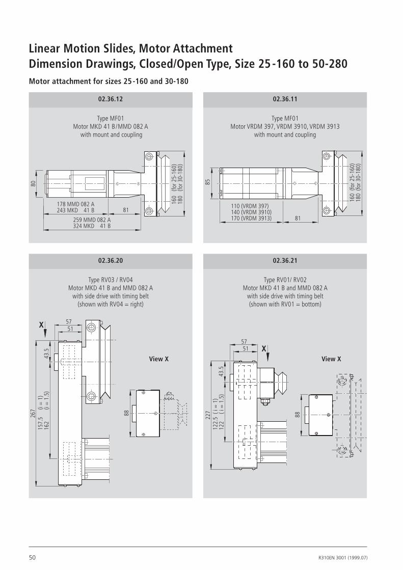
Dimension Drawings, Closed/Open Type, Size 25-160 to 50-280Motor attachment for sizes 25-160 and 30-180
Type MF01 Motor VRDM 397, VRDM 3910, VRDM 3913
with mount and coupling
02.36.11
Type MF01 Motor MKD 41 B/MMD 082 A
with mount and coupling
02.36.12
Type RV03 / RV04 Motor MKD 41 B and MMD 082 A
with side drive with timing belt (shown with RV04 = right)
02.36.20
Type RV01/ RV02 Motor MKD 41 B and MMD 082 A
with side drive with timing belt (shown with RV01 = bottom)
02.36.21
157.
5
(i =
1)
162
(i =
1.5
)
267
43.5
5157
88
X
122.
5 (
i = 1
)12
2
( i =
1.5
)43
.5
227
5157
88
X
81178 MMD 082 A243 MKD 41 B
160
(for 2
5-16
0)18
0(fo
r 30-
180)
80
259 MMD 082 A324 MKD 41 B
160
(for 2
5-16
0)18
0(fo
r 30-
180)
110 (VRDM 397)140 (VRDM 3910)170 (VRDM 3913) 81
85
View X View X
Linear Motion Slides, Motor Attachment
51R310EN 3001 (1999.07)
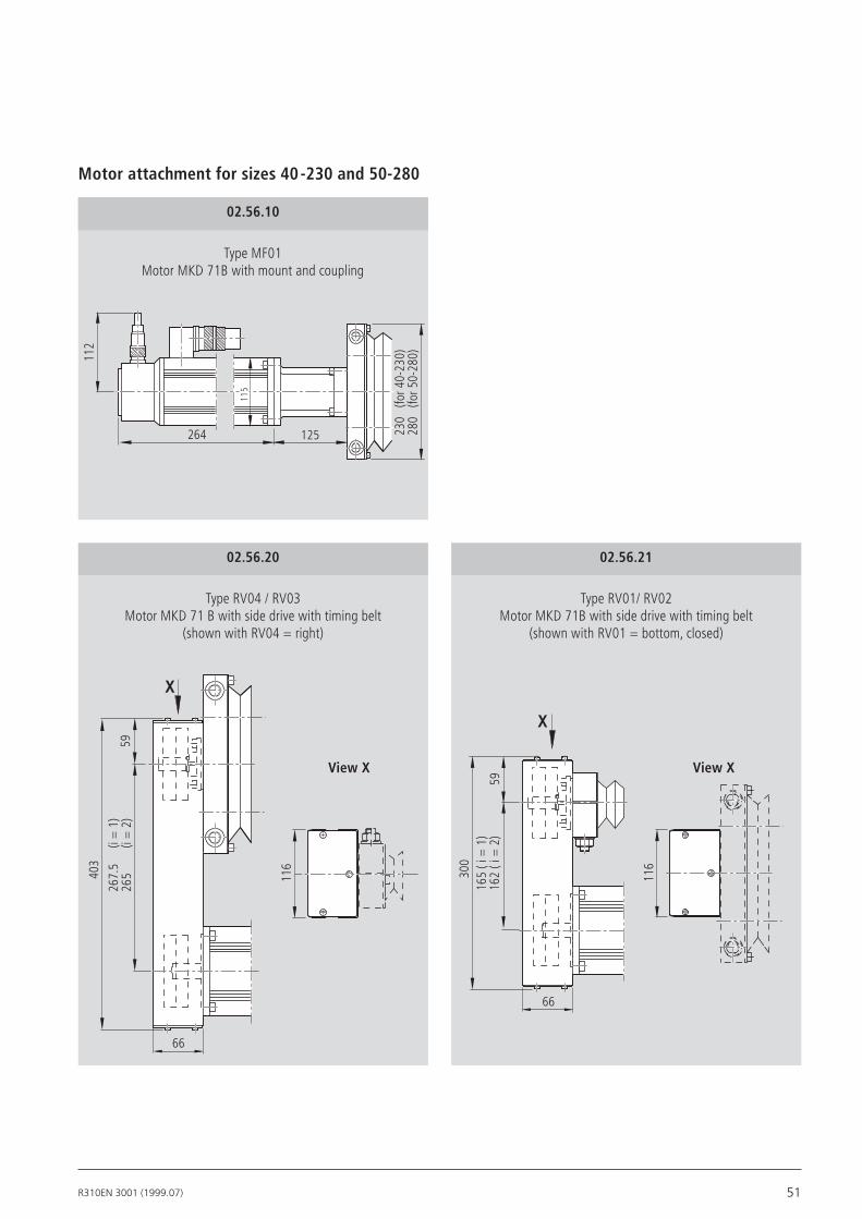
Type MF01 Motor MKD 71B with mount and coupling
02.56.10
Type RV04 / RV03 Motor MKD 71 B with side drive with timing belt
(shown with RV04 = right)
02.56.20
Type RV01/ RV02 Motor MKD 71B with side drive with timing belt
(shown with RV01 = bottom, closed)
02.56.21
Motor attachment for sizes 40-230 and 50-280
267.
5
(i =
1)
265
(i =
2)
403
59
66
X
116
125
112
230
(for 4
0-23
0)28
0(fo
r 50-
280)
264
115
165
( i =
1)
162
( i =
2)
59
300
66
X
116
View X View X
52 R310EN 3001 (1999.07)
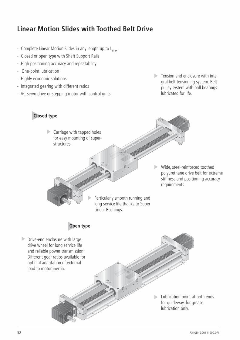
Linear Motion Slides with Toothed Belt Drive
- Complete Linear Motion Slides in any length up to Lmax
- Closed or open type with Shaft Support Rails
- High positioning accuracy and repeatability
- One-point lubrication
- Highly economic solutions
- Integrated gearing with different ratios
- AC servo drive or stepping motor with control units
Closed type
Lubrication point at both ends for guideway, for grease lubrication only.
Tension end enclosure with inte-gral belt tensioning system. Belt pulley system with ball bearings lubricated for life.
Carriage with tapped holes for easy mounting of super-structures.
Wide, steel-reinforced toothed polyurethane drive belt for extreme stiffness and positioning accuracy requirements.
Drive-end enclosure with large drive wheel for long service life and reliable power transmission. Different gear ratios available for optimal adaptation of external load to motor inertia.
Particularly smooth running and long service life thanks to Super Linear Bushings.
Open type

53R310EN 3001 (1999.07)
25-160
Closedtype
JS = ( k1 + k2 · L + k3 · mFr ) · 10-6
k1 1050 152 56.5
k2 0.075 0.083 0.0015
k3 307 34 6.3
Reductioni
1 3 7
Mass moment of inertia of linear motion slide with additional load:
JS Reduced mass moment of inertia of linear motion slide with additional load on the drive journal (kgm2)k1, k2, k3 Constants (see table) mfr Additional load (kg)L Dimension “L” (mm)
Slide Dynamicloadcapacity
C(N)
Dynamicmoments
Mt(Nm)
ML(Nm)
Movedmass
(kg)
SlideweightLinmm(kg)
Max.lengthLmax
(mm)
Drive data without motor (i = 1) : Drive diameter: 35.02 mm Max belt operating force: 520 N Belt type: AT 5, width 32 mm Belt strain: 0.001786 mm/m∙N
Opentype
SGR25-160 11820 520 549 3.2 0.0076 · L + 6.12 3000
SOR25-160 11950 320 339 2.8 0.0112 · L + 5.44 3000
See section on Load Capacities and Moments.Make allowance for reduced load capacity in short-stroke applications and with lift-off loads.
Permissible shaft deflection in the linear bushing for closed type, refer also to section “Technical Notes”
*Speeds of up to 5 m/s are possible. The service life is limited by the increased wear of the plastic material. Tests have shown that a travel of 50 to 100 x 105 m is possible without failure.
Slide Gearingreduction
i
Maximumdrivetorque
Ma(Nm)
Leadconstant
(mm/rev.)
Motorattachment
Maximumspeedv
(m/s)
SGR25-160
SOR25-160
Drive data:
7 1.1 15.72 VRDM 397 MKD41B 1.31
1 9.1 110 - - up to 3*
3 2.6 36.67 VRDM3910 MKD41B 3.06
Depending on the choice of length (L), shaft deflection must be taken into account at the specified load. Shaft deflection must not exceed 3 mm (fmax), since otherwise the toothed belt rubs against the carriage.
If the linear motion slide with toothed belt drive is installed for lift-off loads (i.e. upside down) and shafts longer than 2000 mm are envisaged, please contact us.
fmax Shaft deflection (mm)F External load (N)L Dimension “L” (mm)
f ≤ fmax
L/2
L
F
f
Shaft deflection
fmax = (65.762 · F + 2.451 · L + 2064.4) · L3 · 1-14
fmax = 3 mm
Constant

54 R310EN 3001 (1999.07)
Slide
Drive unit
Components and Ordering SGR and SOR 25-160Linear Motion Slides with Toothed Belt Drive
i = 1 i = 1 i = 3 i = 7
without key-way
01 03
01 03
02 04
10 11
Part number
01 03
01 03
02 04
10 11
Drive unit ..
Standardshafts
Guideway ..
Type
….
MA02
MA03
MG01
MA02
MA01
MA03
MG01
MA01
Dim. drawing 02.34.10
Dim. drawing 02.34.10
Dim. drawing 02.34.60
Dim. drawing 02.34.20Dim. drawing 02.34.30Dim. drawing 02.34.40Dim. drawing 02.34.50
MG02
MG02
SOR25-160
0267-300-00....mm
0263-300-00,....mm
SGR25-160
with key-way
01
01
Journal at right end
Journalat left end
Journal at both ends
Gear unit with push-on
sleeve
Dim. drawing 02.34.11
Dim. drawing 02.34.11
Dim. drawing 02.34.61
Dim. drawing 02.34.21Dim. drawing 02.34.31Dim. drawing 02.34.41Dim. drawing 02.34.51
MG02
MG01
MG02
MG01
Journal at right end
Journalat left end
Journalat both ends
Gear unit with push-on
sleeve
To determine switch activation point see Components and Ordering, e.g. for type SGO.Order example: see Inquiry/Order Form

55R310EN 3001 (1999.07)
10
i = 3
MMD082A
i = 7
29
MKD41B01
60
VRDM391003
10MKD41B01
28VRDM39703
59MMD042A05
Standard i = Motor Type
01
01
01
01
00
10
01
01
01
01
00
*Mount
00
i = 3
MMD082A04
00
for Motor1)
* Attachment can also be supplied without motor. Please enter ”00” for motor on order.
Stan
dard
re
port
Mea
sure
men
t re
port
1) Observe maximum permissible torque.
0201
without switchwithout cable duct
PNP NO
PNP NC 11 - . ±....
External switching
cam
External socket-
plug (loose)
17
Externalswitch
TypeLength in mm
Cable duct(loose)
00
16
13 - . ±....
Mechanical 15 - . ±....
Cable duct 20 - X....
Switch typeMounting side
Switc
h ac
ti-va
tion
poin
t
Switching distanceTravel direction
i = 7
29
MKD41B01
60
VRDM391003
10MKD41B01
28VRDM39703
59MMD042A05
04
04
Motor attachment..
Motor..
Carriage..
1st switch .. - . ± ….. mm 2nd switch .. - . ± ….. mm 3rd switch .. - . ± ….. mm Cable duct .. - . .... mm Socket-plug .. Switching cam ..
Documen-tation ..

56 R310EN 3001 (1999.07)
Dimension Drawings SGR 25-160Linear Motion Slides, Closed Type with Toothed Belt Drive
02.34.10 02.34.60 02.34.20
61.5
1567
.18
10067.18
82
Centering dia. 50 H7 / 4 deep
M6
Mounting hole pattern
L + 25± 0.5
132
± 0.
3
M 12-16 deep
12.5
dia.16h7
A
L/2
31.5
140
77 65
59 25 81
53
3016030
L
4025
31
90
4053
1
58
Max. travel2
M6 -12 deep
Centering dia. 42 H7
4 deep
Lube nipple AM8x1 DIN 3405
Centering dia. 42H7 / 4 deep
77
dia.16h731.5
53 40
5990
40
h=3.8
5P9
203
Centering dia. 42H7 / 4 deep
h=3.8
5P9
203
77
dia.16h7
31.5
dia.16h7
53 40
5990
40
M6 -12 deep M6 - 12 deep
Socket dia. 14H7/ 32 deep for motor journal
Calculating the length: L = max. travel + 220 mm
Effective stroke2
Effective stroke2
Max. travel2
Overrun Overrun
All dimensions in mm
Diagrams to different scales

57R310EN 3001 (1999.07)
M 10 - 22 deep
02.34.30 / MKD 41B 02.34.40 / VRDM 3910 02.34.50 / VRDM 397
10035
82 5361.5
304.515
101.5
8561
.5
171.
515
View A
101.5
8561
.5
201.
515
45 56
dia. 8.4
160
160
88
132
28
89
60
13
61.5
218.
515
99
80
13
61.5
239.
515
Cable gland PG 16 Cable gland PG 16
02.34.70 / MMD 042A 02.34.75 / MMD 082A

58 R310EN 3001 (1999.07)
Dimension Drawings SOR 25-160Linear Motion Slides, Open Type with Toothed Belt Drive
02.34.11 02.34.61 02.34.21
Centering dia. 50H7 / 4 deep
* Same hole spacing at both ends
M6
Lube nipple M8x1
DIN 3405
Verfahrweg max.2
12.5
dia.16h7
A
L/2
31.5
140
77 65
59 25 81
53
3016030
4025
31
90
4053
min 24*120
min 24*
132
3
L
Overrun
Max. travel2
M6 -12 deepCentering dia. 42 H7
4 deep
M6 -12 deep Centering dia. 42H7 / 4 deep
77
dia.16h7
31.5
53 40
5990
40
h=3.8
5P9
203
M6 -12 deep Centering dia. 42H7 / 4 deep
61.5
1567
.18
10067.18
82
Calculating the length: L = max. travel + 220 mm
Effective stroke2
Effective stroke2 Overrun
Max. travel2
77
dia.16h7
31.5
53 40
5990
40
h=3.8
5P9
203
dia.16h7
All dimensions in mm
Diagrams to different scales
Socket dia. 14H7/ 32 deep for motor journal
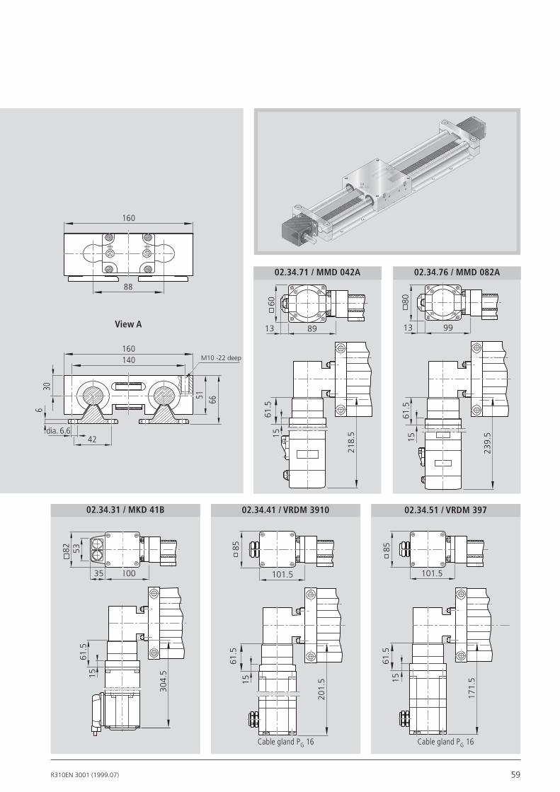
59R310EN 3001 (1999.07)
View A
02.34.31 / MKD 41B 02.34.41 / VRDM 3910 02.34.51 / VRDM 397
M10 -22 deep
101.5
8561
.5
171.
515
101.5
8561
.5
201.
515
10035
82 5361
.5
304.
515
51
160
160
88
66
140
42dia. 6.6
630
02.34.71 / MMD 042A 02.34.76 / MMD 082A
89
60
13
61.5
218.
515
99
80
13
61.5
239.
515
Cable gland PG 16 Cable gland PG 16

60 R310EN 3001 (1999.07)
Reproducibility = ± 0.05 mmPermissible ambient temperature = –5ºC to +80ºCEnclosure = DIN 40050 IP 67Contact time = < 2 msInsulation = group C to VDE 0110Rated voltage = 250 V ACContinuous current = 5 ASwitching capacity at220 V, 40-60 Hz = cosϕ = 0.8 at 2 AContact resistance when new = < 240 mΩConnection = screw connectionContact system = single-pole changeoverChangeover system = snap-action response
Mechanical switch (with mounting components)
Miniature circuit breakers with potted cable(3 x 0.14 mm2 Unitronic), Housing form = NOMinisensor = Form A DIN 41635Voltage = 10...30 V DCResidual ripple = ≤ 10 %Load = 200 mANo-load current = ≤ 20 mASwitching frequency = max. 1500 HzTemperature-related shift in make point = ≤ 4 µm/ºCOutput signal steepness = ≥ 1V/µsReproducibility of make point to EN 5008 = ≤ 0.1 mm
Proximity switch (with mounting components)
1
2
34
6
7
5
Overview of the switching system1 Socket and plug2 Mechanical switch (with mounting components)3 Proximity switch (with mounting components)4 Switching cam5 Cable duct (aluminum alloy)6 Mounting bracket7 Mounting profile
620
40
71
60
12.5
930
10.5
25
30
9
30
71
30
22
60
Cable length: 3 m
Switch Mounting ArrangementsLinear Motion Slides

61R310EN 3001 (1999.07)
50 30
35
12.6
PG 16
51
16-pin plug
Socket and plug• Fit the socket to the side with the most switches (see example on next page). Socket and switch are not wired. The switch activation points can thus be optimized during start-up. A plug is provided. The plug can be mounted in three directions (see figure).
Ordering the switches and mounting components
The part numbers are listed in the table below.
Mounting components can also be ordered individually.
Size
Item 12-85 16-100 20-130/25-160 30-180/40-230/50-280
1 Socket-plug 1414-000-61 2 Mech. switch with mounting components 0236-203-01 Mech. switch without mounting components 8453-040-16 3 Proximity switch - Mounting components without switch 0236-203-02 - PNP NC 8453-040-01 - NPN NC 8453-040-02 - PNP NO 8453-040-03 - NPN NO 8453-040-04 4/6 Switching cam + mount. bracket + mount. comp. 0236-003-03 0236-103-03 0236-203-03 5 Cable duct 0396-620-07 7 Mounting profile 0396-620-08

62 R310EN 3001 (1999.07)
Fitting exampleThe switch position indicates the position of the carriage center (TM) after displace-ment. The zero point is in the center (L/2).
Maximum switching distance = 0.5 ∙ (travel max.) - overrun
For safe operation of the linear motion slide the overrun must be longer than the braking distance.
The acceleration distance may be taken as a guideline for the braking distance.
Observe the minimum possible distance bet-ween switches:mechanical-mechanical = 62 mmmechanical-proximity = 49 mmproximity-proximity = 35 mmHere, the mounting plates must be mounted in mirror image.
0 L/2
TM
right (R)
left (L)
View mechanical switch
View proximity switch
View mounting bracket with cable duct
30A
2.5+0.2
43
37
C
55
33
D
0.4+0.2
17
20
5B
3030
A
Slide Dim. A Dim. B Dim. C Dim. D
SGK 12-85 5.5 27 +4 +0.5
SGK 16-100 5.5 30 +6 3.5
SGK 20-130 6.5 40 4 13.5
SGK 25-160 6.5 40 7 16.5
SGK 30-180 7.5 40 14 23.5
SGK 40-230 9.0 40 2 11.5
SGK 50-280 9.0 40 2 11.5
Slide Dim. A Dim. B Dim. C Dim. D
SOK 12-85 5.5 27 +2 1.5
SOK 16-100 5.5 30 +2 7.5
SOK 20-130 6.5 40 6 15.5
SOK 25-160 6.5 40 9 18.5
SOK 30-180 7.5 40 17 26.5
SOK 40-230 9.0 40 7 16.5
SOK 50-280 9.0 40 9 18.5
The switch is mounted in the same way for all sizes:
The spacing for the mechanical and proxi-mi ty switches must be adjusted when mounting the switch.
Depending on the relevant operating con-ditions (vibrations, center of switch stroke), the switch mounting profile may have to be supported.
Negative values mean that the switch projects above the top edge of the carriage.
Cable duct
for 1
2 - 8
5
Adjust when mounting
- +
Recommended standard switch fittings:
- 2 mechanical switches
- 1 proximity switch
Slide mounting plates with switches into the groove and fix with the screws and square nuts.
Switch Mounting ArrangementsLinear Motion Slides

63R310EN 3001 (1999.07)
AC servomotors
MKD 71B-097-KG1
9.5
40
3
dia.
95
j6
dia.
19
k6
264
45° 45°
1159
130
9.5
40
3
dia.
95 j
6
dia.
19k6
264
45° 45°
1159
130
MKD 41B-144-KG1
MKD 71B-061-KG1
MKD 25B-144-KG1
7
45° 45°
20
2.5
dia.
40 j
6
dia.
9k6
564.5
63
233
Motor MKD25B MKD41B MDD71B
Max.effectivespeednm (1/min)
RatedtorqueMMN (Nm) 0.9 2.7 8
(Nm)
(.10-6kgm2) 30+8 170+16 870+38
BrakeholdingtorqueMBr (Nm) 1.0 2.2 5.0
MasswithbrakemBr (kg) 2.25 4.65 9.17
MaximumtorqueMMmax
MassmomentofinertiaJM+JBr
AC servomotor data
Part number 8611-010-03Part number 8611-050-03
Part number 8611-011-03 Part number 8611-012-03
Motors
8
45° 45°
30
2.5
dia.
50
j6
dia.
14k6
826.6
95
243

64 R310EN 3001 (1999.07)
MiniDrive
Part number 8611-060-03MMD 082A
73
30 X
Y
50 h7
45˚ 45˚
60
4.5 70
8335
70 h
7
177.5
19 h
6
45˚ 45˚
80
6.0 90
MMD 022APart number 8611-059-03
MMD 042APart number 8611-058-03
Type X Y
MMD 022A 127 11h6
MMD 042A 156.5 14h6
MiniDrive motor data
MMD022AMotor
Ratedspeednmax (1/min)
RatedtorqueMMN (Nm)
MaximumtorqueMmax (Nm)
MassmomentofinertiaJM+JBr (10-6kgm2)
BrakeholdingtorqueMBr (Nm)
MasswithbrakemBr (kg)
MMD042A MMD082A
3000
2.4
6.9
133 + 8
2.4
3.7
3000
1.3
3.36
37 + 3
1.3
2.0
3000
0.64
1.91
17 + 3
1.3
1.4
MotorsLinear Motion Slides
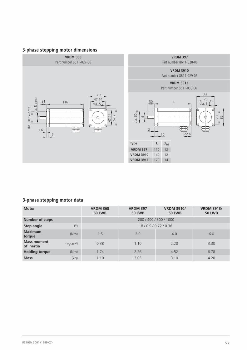
65R310EN 3001 (1999.07)
3-phase stepping motor dimensions
3-phase stepping motor data
VRDM 3910Part number 8611-029-06
VRDM 397Part number 8611-028-06
VRDM 3913Part number 8611-030-06
VRDM 368Part number 8611-027-06
dia.
8-0
.013
dia.
38.
1±
0.02
5
21
1.65
11647.1457.2
dia. 5.2
57.2
47.1
4
ckkvrdm36850mt.eps
Type L dh6
VRDM397 110 12
VRDM3910 140 12
VRDM3913 170 14
Motor VRDM368 VRDM397 VRDM3910/ VRDM3913/ 50LWB 50LWB 50LWB 50LWB
Numberofsteps 200 / 400 / 500 / 1000
Stepangle (°) 1.8 / 0.9 / 0.72 / 0.36
(Nm) 1.5 2.0 4.0 6.0 (kgcm2) 0.38 1.10 2.20 3.30
Holdingtorque (Nm) 1.74 2.26 4.52 6.78
Mass (kg) 1.10 2.05 3.10 4.20
MaximumtorqueMassmomentofinertia
d
dia.
60
h8
30
2
10
L7085
dia. 6.5
8570
22.6

66 R310EN 3001 (1999.07)
Standard reportOption 01
The standard report serves to confirm that the checks listed in the report have been carried out and that the measured values lie within the permissible tolerances.
Lead deviation of ball screw for SGK and SOKOption 03
In addition to the graph (see diagram), a measurement report in table form is provided.
Checks listed in the standard report:– functional checks of mechanical compon-
ents– functional checks of electrical compon-
ents– design is in accordance with confirmati-
on of order
Moment of friction measure-ment of the complete systemOption 02
The moment of friction is measured along the entire travel.
-300
200 400 600 800 1000 1200 1400
Measured travel (mm)
Dev
iati
on
(m
m)
1600 1800 20000
300
-240
240
-180
180
-120
120
-60
60 0
0
M (Nm)
M (Nm)
t (ms)
Forwardmotion Backwardmotion
DocumentationLinear Motion Slides

67R310EN 3001 (1999.07)
Order example: Linear motion slide with linear bushings and shafts
Linear Motion Slides
Ordering data Description
To be completed by customer: Inquiry / OrderLinear Motion Slide __________________________________
(Part number): _______-_______-_______, length _________mm
Type =
Guideway = Drive unit = Carriage = Motor attachment = Motor = Cover = 1st switch = - + mm2nd switch = - ± mm3rd switch = - – mmCable duct = , mmSocket-plug = Switching cam = Documentation =
Linear motion slide SKG 25-160(Part number): 1160-260-00, 1310 mm
Type = MF01
Guideway = 01Drive unit = 03Carriage = 01Motor attachment = 01Motor = 08Cover = 011st switch = 15-R+ 390 mm2nd switch = 11-R– 290 mm3rd switch = 15-R– 390 mmCable duct = 20, 1200 mmSocket-plug = 17Switching cam = 16Documentation = 03
Components:
Motor mount
(Part number): __________-__________-__________
Inquiry/Order Form
Bosch Rexroth AGLinear Motion and Assembly TechnologiesErnst-Sachs-Straße 10097424 Schweinfurt, Deutschland
Number of units Quantity:____ pcs., _____ per month, ______ per year, per order, or ____________________________
Comments:
From OEM User Distributor
Company: ___________________________________________ Contact: ___________________________________________
Address: ___________________________________________ Position: ___________________________________________
___________________________________________ Telephone: ____________________________________________
___________________________________________ Fax: _________________________________________
___
Documentation
Slide designation SKG, length = 1310 mm
with mount and motor, mounted as in diagram MF01Linear Bushings and Shaftsball screw 20 x 20carriagewith mount for motormotor MKD 41 Bpolyurethane bellowsmechanical switch, switch activation point: right + 390 mmPNP NC, switch activation point: right – 290 mmmechanical switch, switch activation point: right – 390 mmcable duct 1200 mm long (loose)socket-plug on switch sidefor switch activationlead deviation chart for ball screw
Telephone + 49-9721-937-0
Telefax + 49-9721-937-350 (direct)
Bosch Rexroth AGLinear Motion and Assembly TechnologiesErnst-Sachs-Straße 10097424 Schweinfurt, GermanyTel. +49 9721 937-0 Fax +49 9721 937-275www.boschrexroth.com/dcl
Subject to technical modifications
© Bosch Rexroth AG 2010Printed in GermanyR310EN3001 (1999.07)EN • DCL/MKT
Find your local contact person here: www.boschrexroth.com/addresses-dcl


