Download - LJ - Lehigh University

I~, LJ RGpoaf 303.£/'YVO~
\ .

LATERAL WEB DEFLECTIONS OF WELDED TEST GIRDERS
by
Kyle E. Dudley
A Thesis
Presented to the Graduate Faculty
of Lehigh University
in Candidacy for' the Degree of
Master of Science
fRITZ ENGINEERINGJLABORATORY UBRARY
Lehigh University
May 1966
·f-··


303.4
ACKNOWLEDGEMENTS
iii
I •
The experimental work which lead to this thesis_ was .. sponsored
by the Pennsylvania Department of Highways in conjunction with the
United States Department of Commerce - Bureau of Public Roads and
the American Iron and Steel Institute and American Institute of
Steel Construction through the Welding Research Council. The
research was conducted at Fritz Engineering Laboratory, Department
of Civil Engineering, Lehigh University, Bethlehem, .Pennsylvania.
Professor Lynn S. Beedle is Director of the .Laboratory.and.Acting
Head of the Department. Professor William J. Eneyis .Head of the
Department. The sponsorship of the organizations. and .the general
guidance of the professors are acknowledged.
The author is indebted to Professor B. T. Yen for his guidance
and advice on this thesis. The help.thatMr.JohnA. Mueller
provided in all aspects of the.invest.igation..and_the.assis.tance
given by Mr. Heribe.rto Izquierdo in the preparation oLdata .and.
figures are gratefully acknow.ledged..Apprec.iation.isalso. extended
to Mr. Leonard Brooks forthe-. drafting of. the .. figures and to
Miss Marilyn·Courtright for the typing of the manuscript.

303.4
. TABLE OF CONTENTS
ABSTRACT
I. INTRODUCTION
1.1 Background and Scope
1.2 Causes of Initial Lateral Web Deflections
1.3 Specimens for Deflection Measurements
1.4 Method of Measuring Lat~ralDeflections
II. INITIAL LATERAL WEB DEFLECTIONS
2.1 Initial· Deflected Shapes
2.2 Magnitude of Initial Lateral Deflections
III. LATERAL DEFLECTIONS AT WEB BUCKLING LOADS
IV. LATERAL WEB DEFLECTIONS AT TlWORKING LOAD!!
4.1 TlWorking Load Tl Defined
4.2 Lateral Deflections Under Bending
4.3 Lateral Deflections Under Shear
4.4 Lateral Deflections Under Bending and Shear
V. SUMMARY
TABLES
FIGURES
REFERENCES
VITA
iv
Page
1
2
2
2
3
5
7
7
9
12
14
14
14
16
18
'20
22
30
58
60
303.4
LIST OF TABLES
v
Table Page
1 DIMENSIONS OF COMPONENT PARTS 22
2 CHARACTERISTIC LOADS OF TEST GIRDERS 24
3 EXAMPLE OF WEB DEFLECTION DATA 25
4 MAXIMUM INITIAL LATERAL DEFLECTIONS OF 26
TEST GIRDERS
303.4
Figure
1
2
3
4
5
6
7
8
9
10
11
12
13
14
15
16
LIST OF FIGURES
Specimens and Loading Condition,Girders Gl - G5
Spectmens and Loading Condition,Girders El -E5, G8 - G9
Specimens and Loading Condition,Girders G6 & G7, Fl -F5
Specimens and Loading Condition,Girders Hl and H2
Specimens and Loading Condition,Girders F6 and F7
Specimens and Loading CGndition,Girders F8 and F9
Dial Gage Rig for Web Deflection Measurements
Initial Web Deflection Shapes, Single andDouble Curvature (Girder G9)
Initial Web Deflection Shapes, TripleCurvature (Girder G4)
Maximum Initial Deflection Versus WebSlenderness Ratio
Maximum Initial Deflection Versus LargestPanel Dimension
Maximum Initial Deflection Versus Web Thickness
Initial Web Deflection Contours
Lateral Deflection Versus Applied Strain Fr~m
Ref. 12
Load-Deflection Curves for Panels in Bending
Load-Deflection Curves for Panels in Shear
Page
30
31
32
33
34
35
36
37
37
38
39
40
41
42
43
44
vi

303 ;4
, Figure
17
18
19
20
21
22
23
24
25
,26
27
28
29
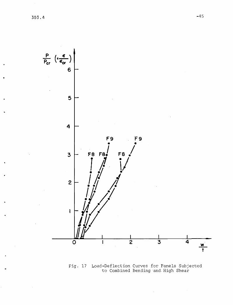
Load-Deflection Curves for Panels Subjected toCombined Bending and High Shear
Sequence of Web Deflection Growth,Girder G4, Panel 2
Gradual Change of Deflection Contours,Girder F7, Panel 3
Deflected Cross~Sectional Shapes Under Bending,Girder G5
Deflected Cross-Sectional Shapes Under Bending,Girder Gl
Overall View of Girder Gl
Web Deflection Contours, Girder F6, Panel 3
Web Deflection Contours, Girder F8, Panel 2
Web Deflection Contours, Girder G6, Panel 1
Shear Deflection Patterns, Girder El
Web Deflection Contours, Girder F8, Panel 3
Web Deflection Contours, Girder F8, Panel 5
Initial and Deflected Cross-Sectional Shapesof End Panels
vii
45
46
47
48
49
50
51
52
53
54
55
56
57

303.4
ABSTRACT
This thesis examines the lateral web deflections of twenty
four full sized welded test girders. The purpose of this
investigation was to study the web behavior and attempt to
establish trends and deflection patterns in connection with
different loading conditions.
-1
\-
Initial deflected~shapes are discussed, including their effect
on deflected web shapes resulting from applied loads. Sudden web
movements at critical buckling loads are found to be nonexistent,
at least in the test girders investigated. Nominal deflected
shapes at TTworking loads TT are established, and the phenonemon of
lateral web deflection is discussed in detail.

303.4 -2
I. INTRODUCTION
1.1 Background and Scope
Even before work first began on the strength of welded plate
girders, it was realized that there was always a certain amount of
initial variation from a flat surface in the web plates of fabri-
cated girders. Statically, these initial lateral web deflections
. (1 2 3 4)do not appear to affect the strength of a glrder. '"
However, when considering the stresses in the web initial lateral
web deflections must be taken into account. The purpose of this
report is to examine the characteristics of initial lateral web
deflections and to evaluate their effects on web deflection
patterns under load for future stress analysis.
1.2 Causes of Initial Lateral Web Deflections
The causes of initial lateral web deflections are generally
attributed to the manufacturing of girder materials and the fabri-
cation of girders. Web plptes are hot-rolled into a flat plane at
temperatures above 1333 degrees Fahrenheit. As cooling takes place
at different rates throughout a plate, non-uniform contraction of
the plate results and residual stresses of varying mangitudes are
formed.(5) These residual stresses cause the initial out-of-flat-
ness of the plate.

303.4
During fabrication of a girder, web plates are usually
-3
pushed and pulled along the edges so that the flanges and stif
feners may be spot-welded into place. When final welding takes
place, the web plate is heated once again, and the cooling induces
new 'residual stresses which, in turn, create out-of-flatness in
the web.(5) The combined effects of plate rolling, forced
fitting, and welding cause the initial lateral web deflections in
welded plate girders that are discussed in this report.
1.3 Specimens for Deflection Measurements
To acquire information on lateral web deflections, extensive
measurements were taken on twenty-four large-sized test girders
containing a total of 119 panels. The testing of these girders
included both static and fatigue applications of loads in shear,
bending, and combined bending and shear. By loading configuration
and material properties, these girders can be grouped into six
series. These are sketched in Fig. 1 through Fig. 6.(1,6,7,8,9)
All girders were designed to accommodate the desired loading
condition in the "test sections". The only geometric feature
common to all test girders was a uniform web depth of fifty inches.
This and other geometric properties are given in Table 1, and the
characteristic loads are summarized in Table 2. In all girders,
the welding sequences used by the various fabricators were in
accordance with current practice. The sizes of the welds were
determined in consideration of test objectives, and not always
according to AWS specifications.(1,6,7,8,9)

303.4 -4
The first series of girders, Gl, G2, G3, G4, and G5 (Fig. 1),
were made of ASTM-A373 steel and were loaded with pure bending in
the test section between the web butt welds. Girders G3 and G5
differed from the others in that continuous pipes were used as top
flanges in place of rectangular plates. The second group of girders,
El, E2, E4, E5, G8 and G9, all tested under combined bending and
high shear, were also fabricated from ASTM-A373 steel. The E
girders were fabricated by welding together the unharmed end
sections of the tested girders Gl, G2, G4, and G5, respectively.
The details of these girders can be seen in Fig. 2.
The group of girders tested in high shear included glrders G6,
G7, Fl, and F2 (ASTM-A373) along with F3, F4, and F5 (ASTM-A36).
A representative specimen and the test setup are illustrated in
Fig. 3. As in most of the other gr~ups, the stiffener spacing
differs from girder to girder as well as within the specimen.
This variation is listed in Table 1 as the aspect ratio,~ , of
panel length to web depth. Also listed for all girders is the web
slenderness ratio , 13 , the web depth to thickness.
Girders Hl and H2 were constructional alloy steel girders
subjected primarily to shear. The specimens and loading conditions--'
were similar to those of the E series and are sketched in Fig. 4.

303.4 -5
V
The last two groups of girders had two-point loading setups
as shown in Fig. 5 and 6. Each group had two identical girders
of ASTM-A36 steel. The test sections of F6 andF7 were the pure
bending portions between the load points (Fig. 5). F8 and F9 had
unsymmetrical cross sections outside of the load points. There,
the smaller top flanges 'caused the neutral axis to lie below mid
depth of the web, thus emphasizing any lateral deflection of the
compression part of the web.
The weld and stiffener sizes of all girders are indicated in
the sketches of the girders. For other details, material properties,
and computation of characteristic loads, reference is made to the
test reports of the girders (Ref. 1,6,7,8,9).
1.4 Method of Measuring Lateral Deflections
Lateral web deflection measurements were taken using an Ames
dial gage rig. This is a 49 inch-high frame with a number of
O.OOl-inch Ames dial gages mounted in a horizontal direction along
the height as shown in Fig. 7. The number of dial gages varied
from five to eleven depending on type o,f loading condition and the
chronological sequence of testing. As the investigation progressed
from the static strength of girders to their fatigue behavior, and
then to web deflection pattern, more dial gages were used. Also
increased were the number of positions where the dial rig was
stationed.

303.4 -6
For measurement, the dial rig is held vertical with its lower
leg resting at the web-to-bottom flange boundary and its upper leg
temporarily fixed to the web by a magnet just below.the top flange.
By placing the rig first on the 50-inch deep girder web and then
on a sturdy, flat surface and comparing the corresponding dial
readings, the lateral position of web points could be obtained.
Table 3 gives an example of recorded data and computation of
lateral web deflections along one vertical cross section of a
girder.
It should be mentioned that any lateral deflection of the top
flange with respect to the bottom flange is not recorded by this
method. For the purpose of obtaining lateral deflections of the
web with respect to its bo~ndary, the dial rig has proved to be
very convenient.

,
I -
303.4 -7
II. INITIAL LATERAL WEB DEFLECTIONS
2.~ Initial Deflected Shapes
From measurements made on the girders presented in Chapter 1,
it was found that none of the webs were initially plane.
In order to study initial web deflections, cross-sectional
shapes of girders at locations of measurements are sketched.
Examples are given in Fig. 8 which includes 6 vertical cross
sections in two panels of a girder.(l) In each section, the
measured positions of the web points are connected by straight
lines to depict the approximate shape of the cross section. With
the enlarged scale for lateral deflections, it can be seen clearly
that all sections in this figure are not plane. Two of these
cross-sections have single "curvature" and the rest have reversed
curvature.
The effects of welding sequences on these initial lateral
deflections have been examined to a degree limited by available
information. For all the girders of which the welding sequence is
provided by the fabricators,(7,8,9) no consistency can be found on
the number of "curvatures" or on the direction of deflection. It
is believed that the influences of plate flatness and fabrication
procedures (fitting and welding), not the latter alone, determine
the initial deflected shape.

303.4
In theory, a cross section can have any initial deflected
shape as determined by the flatness of the web plate and the
fabrication procedure. In this study, almost all cross-sections
-8
have single, reversed or triple curvature as illustrated in Figs. 8 & 9.
Of nearly 300 cross sections from the 24 test girders, about 60
percent had single curvature and 20 percent each were with double
or triple curvature.
Perhaps a good way to compare the shapes of initial deflection
is to consider the web depth and the web thickness, or the web
slenderness ratio of depth to thickness. Figure 10 shows this ratio
w. It plotted against CS), where w. is the maximum initial1 max 1 max
lateral deflection of the web at a specific cross section and t the
thickness of the web. For the moment, consider only S and its
relation to the three types of deflected shape represented by the
different symbols in the figure. It is clearly evident that a
majority of cross sections with single curvature fall in the lower
ranges of S while double and triple curvature occur mainly in the
higher ranges ofS. In other words, the more slender the web, the
more likely it is to have initially deflected shapes,with double
or tripie curvature.
Such a result is obviously expected and can be extended to the
horizontal cross sections. By examining the 119 panels measured,
it was found that about 90 percent of them contained initial
single-waved shapes in horizontal cross sections. All horizontal

303.4 -9
)
cross sections with doubl~ or triple curvature were in panels with
aspect ratios much greater than one, in fact with stiffness
spaced at distances two to three times the depth of the web.
The significance, or unsignificance of the initial deflected
shapes is discussed in following sections. The point to make here
is that, given a plate girder web panel, there can be assumed some
initial deflections with a cross-sectional shape of single, double,
or triple curvature as shown in Figs. 8 and 9.
2.2 Magnitude of Initial Lateral Deflections
The quantitative results from measuring initial lateral
deflections of girder webs are partially summarized in Table"4.
Listed in this table are the maximum initial lateral deflection
values for all girders, the ratio of these deflection magnitudes
to the web depth, and the ratio of the same magnitudes to the
corresponding web thickness. The highest value of initial lateral
deflection was 0.642 inches, recorded in girder G9 in a 75 inch
by 50 inch panel with a 1/8 inch web thickness (~ = 1.5, e = 382).
Current practice specifies that the out-of-flatness of a
girder web shou~dnot be more than 1/150 of the maximum vertical
or horizontal unstiffened dimension for web thicknesses greater
than 1/150 of web depth, and not more than 1/120 of the maximum
vertical or horizontal unstiffened dimension for web thicknesses
less than 1/150 of the web depth.(lO) All except one of the test

•
303.4 -10
girders conformed to this specification. The only initial
lateral deflection which was higher than allowecl by this speci~
fication was at the same place where the highest value of web
deflection was ever recorded in these test series.
The values in the last column of Table 4, as well as values
from all measured panels have been plotted in Fig. 10. By
examining this figure, it can be seen that initial web deflections
vary from about 5 percent to more than 3 times the web thickness
for the girders of this report. It is evident that more slender
webs have larger initial deflections as compared to the web
thickness. Below ~ = 200, no deflection larger than the web
thickness was measured. For higher values of ~, the magnitude of
deflection extends over a wide range. ' However, it should be pointed
out that stiffener spacing may also playa role. Almost all the
cases of large deflections (say more than 2 times the web thickness)
were obtained from slender-web panels with stiffeners positioned far ~
apart (Ct' > 1. 5) .
To incorporate both slenderness ratio and stiffener spacing in
examining initial web deflections, Fig. 10 is modified to show the
relationship between w. It and the ratio of the larger panel1 max
dimension to the web thickness, Fig. 11. From this figure, it can
be concluded that both the magnitude of the non-dimensionalized
initial deflection, as well as the variation of the magnitude,
increases when the larger panel dimension increases.

303.4 -11
.-
Further discussion on the maximum magnitudes of initial web
deflections can be made if more data are ava.ilable. For example,
Fig. 12 compares the maximum deflection with the web thickness.
A statistical analysis can be made if there are enough data to be
included. For the time being, one could only arrive at the
reasonable speculation that the possible out-of-flatness of girder
webs is inversely proportional to the web thickness.
Before leaving the subject of magnitude of initial web
deflection, the variation·of the magnitude within a girder panel
should be examined. To do so, a web deflection contou~ diagram is
drawn for a panel of girder F6 and is shown as Fig. l3(b). Solid
lines indicate equal deflections toward the reader, dotted lines
into the paper. This panel has lldouble curvature ll vertical cross
sectional shapes. Delfections increasefrom.zero at the panel
boundary to about 0.15 inches and 0.12 inches at the ridge and the
valley, respectively. Distances between contour lines are
relatively far and uniform, indicating gradual change of deflection
magnitude anywhere within the web. Such is the typ~~al pattern of
magnitude changes for all the girder panels after fabrication.
This is further seen in Figs. 13(a) and 13(c) for single and triple
Ilcurvaturell panels. Further examples will be given in later
sections in connection with deflections under load.

303.4 -12
III. LATERAL DEFLECTIONS AT WEB BUCKLING LOADS
Theoretically, plane webs of plate girders buckle at critical
loads which are determined by the loading and boundary conditions
and.the geometry of the web.(ll) In the series of test girders
reported here, there were no initially plane girder webs (as
pointed out in Chapter 2) and the buckling phenomenon was not
( 1 6 7 8 9)observed. ""
By considering simple forms of initially deflected shapes and
simple boundary conditions, deflections below and above the theo
retical web buckling load can be computed for a few cases.(ll)
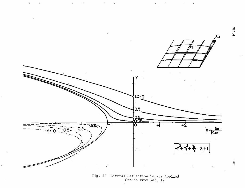
Figure 14 shows the result for a simply supported rectangular plate
under a given edge strain by using the energy method and la~ge
deflection theory of Plates.(2) The ordinate in the figure (Y)
represents non-dimensionalized lateral web deflection of a point in
the web, and the abscissa is the applied strain in terms of the
theoretical web buckling strain (e/e). If there exist certaincr
initial lateral deflections (Y. :f 0 at e /e = 0), their magni-1 a cr
tudes increase as compressive strain is applied to the web. There
is no sudden buckling to be observed unless the web is originally
plane.
The qualitative results of Fig. 14 are typical of plate girder
webs under other types of loading and boundary conditions. This is
borne out by measuring the lateral deflections of web points and

303.4 -13
plotting their magnitudes against the applied loads.. Figures 15 ,
16, and 17 are three plots of this kind for.points in the compres-
sive regions of panels subjected to bending, shear, and combined
bending and shear, respectively. The ordinate of PiP. is equicr
•
I •
valent to that of e/e within the elastic limit of the. materialcr
and the values of wit are similar to those of Y in' Fig. 14. The
fact that there was not buckling when the applied loads were. equal
to the critical loads (P/Pcr= 1), is signified by the continuity of
the curves and absence of sudden change in these figures. From the
initial magnitudes, deflections increased or decreased gradually as
loads were increased to and above the buckling values.
In Figs. 15, 16, and 17, it can be seen that the rate of
deflection varied from curve to curve as well as long each of them.
The randomness of these curves does not indicate a direct corre-
lation of loads and the rates of deflection. There does not seem
to be any elastic increase of rates at thew.eb ..buckling .. load.
Because of these observations, and the result drawn from
static strength studies that Pcrhas no.bearing on the load carrying
capacity of girder panels, (1) _web .buckling.loads.are not
considered significant in this report. Further. examination' of
web deflections is directed at those corresponding to TTpost
buckling TT loads for possible deflection trends and patterns .
303.4 -14
IV. LATERAL WEB DEFLECTIONS AT TTWORKING LOAD TT
4.1 TTWorking Load TT Defined
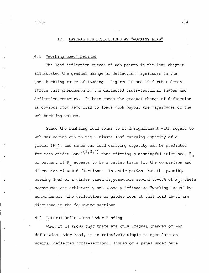
The load-deflection curves of web points in the last chapter
illustrated the gradual change of deflection magnitudes in the
post-buckling range of loading. Figures 18 and 19 further demon-
strate this phenomenon by the deflected cross-sectional shapes and
deflection contours. In both cases the gradual change of deflection
is obvious from zero load to loads much beyond the magnitudes of the
web buckling values.
Since the buckling load seems to be insignificant with regard to
web deflection and to the ultimate load carrying capacity of a
girder CPu).' and since the load carrying capacity can be predicted
for each girder panel C2 ,3,4) thus offering a meaningful reference, Pu
or percent of P appears to be a better basis for the comparison andu .
discussion of web deflections. In anticipation that the possible
working load of a girder panel is~omewhere around 55-65% of Pu,these
magnitudes are arbitrarily and loosely defined as TTworking loads TT by
convenience. The deflections of girder webs at this load level are
discussed in the following sections.
4.2 Lateral Deflections Under Bending
When it is known that there are only gradual changes of web
deflection under load, it is relatively simple to speculate on
nominal deflected cross-sectional shapes of a panel under pure

•
303.4 -15
bending. The part of the web under compressive stress would tend
to bulge out, whereas the part under tensile stress would be~~--==--;::...-.------'-------_.._--_.-:-~-_ ..._.,-_.,....._,.~_.~_ ..~._._="-~--~.,.~--_._-<._ ..-.~ ..,~..
stretched toward a flat surface. This trend is clearly indicated
by the successive cross-sectional shapes at increasing loads in
Fig. 18. The deflected shapes in Fig. 20 provide further evidence
of this nominal bending deflection pattern.
Naturally, the initial deflections and the boundary conditions
of a panel affect the deflection pattern under load. The cross-
sections in Fig. 18 (G4) and those in the two smaller panels of
Fig. 20 (G5) and lItriple curvature ll with little initial deflection
at the neutral axts (y=O). The increase and decrease of deflection
magnitudes under load as described above, thus, is easily seen,
The initial shapes of the sections in the long panel of Fig. 20 were
of lIdouble curvature ll• When subjected to bending, the increase of
deflection above the neutral axis forced the web below to. conform and
to move across the flat plCj-ne to the other side, resulting in lI s ingle
curvature ll deflected shape~. In Fig. 21, the initial deflected
shapes of girder Gl were all of lI s ingle curvature ll. At the working
load, in the long panel, the compression region deflected lqterally~-------~-------------~-~.------ ----
quite an amount and forced th~ ..web__in the tens ion region tCL.in.cr.e.as.e...------------._----~--_.-_.._.-~- - - ---~--
(rather than decrease) the magnitudes of deflectiQn. The relatively_.~.~_. '__'''''''-''__''_''M~__~'_ ~ ..... _.
_.- ....-.---_.- -._-----,..--'-------_._-----large lateral deflection under load is due to the tilting of the
slim compression flange (Fig. 22). In fact, the tilting, which
eventually caused the failure of the girder in testing, was the
reason for the cross section (x=-25) in the neighboring panel to
deflect opposite to its initial direction.

303.4 -16
I .
Therefore, the pattern of web deflection under pure bending
depends on the initial deflections. The magnitude of load,. and
the boundary conditions of flange and neighboring panels. Their
relative importance differ for each panel. One case has been
observed (F6) where the direction of deflection of the whole
panel was completely reversed from that of the initial deflection
.because of the deflection patterns in the neighboring panels and
the movement of the flange. Nevertheless, for the majority of the
panels in,bending the nominal trend seems generally true that web
deflections tend to increase above the neutral axis and decrease
below the neutral axis. This trend, and the nominal deflection
pattern, are depicted by the deflection contours in Fig. 23 for a
panel of girder F6.
4.3 Lateral Deflections Under Shear
The tendency of deflection is quite definite for panels under
shear. The pattern of deflection, however, is strongly influenced
by the initial deflections.
Figure 24 shows the initial and subsequent deflections of a
panel of girder F8 under load, and serves as a typical example of
the trend. When shear force was applied to the panel and tension
field action induced,(3) the web plate was stretched and remained
straight in the general direction of the tension diagonal. Along
the compression diagonal, the applied force shortened the distance
and caused lateral deflections. The result was the typical,

303.4 '. -17
inclined pattern of deflection contours for panels under shear.
The panel in Fig. 24 had "double curvature" initial deflections.
This panel could be divided into two parts of fairly even shape,
with the upper.half bUldging into the plane and the lower half out
of the plane. Under shear, when the inclined pattern took shape,
the panel still could be.divided fairly uniformly into two parts.
The dividing line of zero.deflections was in the general direction
of the tension diagonal. The upper and the lower half had about
the same maximum magnitude of deflection. In Fig. 25, the panel
had "single curvature" deflections at the left and a fairly flat
web at the right. When subjected to shear, the typical trend of
inclined tension diagonal was identical to.that of Fig. 24, but the
deflection pattern naturally assumed a single, dominant valley. In
the lower-righthand corner, the small ridge out of the plane
evidently indicated the influence of the initial condition there.
Unlike the cases in bending where they were the main load
carrying components, the flanges carry little stress in the shear
girders. Thus, their influence on the web deflections are much
less prominent than before. The possible influencing boundary
conditions were the stiffeners and the deflection patterns of the
neighboring panels. Plate stiffeners, such as those reported here,
provided strength for tension field action as well as rigidity
against transverse deflections at the stiffener. Against twisting,
as a result of lateral web deflection, they offered only small

303.4
resistance. Consequently, if lateral deflections of the web on
one side of a stiffener are predominant, they may well force the
web on the other side to deflect in the opposite direction.
This conformity of neighboring panels was observed for all the
test panels in shear.
-18
For all panels in shear, the overall influence of initial
deflection appeared,to be dominant in the formation of the
specific panel deflection pattern at working load. Regardless of
this specific pattern, the general trend is definitely toward
inclined deflection contours, Fig. 26.
4.4 Lateral· Deflection Under Bending and Shear
For plate girder panels, the loading condition is ei!her _pure
bending or combined bending and __ shear. No pure shear cases exist.
Thus, the trend and patterns of deflection under shear, as
discussed in last section, are actually for cases where the effects
of shear dominated and those of bending moments were negligible.
From this point of view, the examination of web deflections under
bending and shear should be made by tabulating their relative
magnitudes and comparing the corresponding deflection shapes.
Practically, for panels of the test girders where tension field
action existed, the trend of shear deflection was observed,
regardless of the magnitude of bending. The effects of bending
moments were mainly on the magnttude of deflections.

303.4 -19
This is illustrated by Fig. 27 and 28 which are the deflection
contours of two panels of girder F8. Both panels had unsymmetrical
cross sections with their neutral axes about. seven inches below the
midheight to emphasize the bending effect (Section 1.3). The static
failure mode of both were governed by bending, that is, failure of
the compression flange. Yet, when subjected to bending an shear,
the prominent deflection pattern was that of shear. In Fig. 27,
the panel has higher initial deflection magnitudes at the upper
portion of the web do the larger deflections there under load might
not be all due to bending. The panel of Fig. 28 was very close to
being planar initially. Here the deflections at load could
.definitely reflect the influence of shear to form the diagonal
deflection contours and the effect of bending moments to increase
the magnitude of deflection in the compression region.
Since the loading is a combination of bending and shear,the
influence of initial deflections and boundary conditions are, by
speculation, that of bending and shear superimposed. The conformity
of deflection directions in the panel of Fig. ~7was typical of
shear loading, as was the formation of the small valley in the panel
of Fig. 28 when subjected to load. The flange had remained
straight and exerted no apparent influence on the web deflection of
these two panels. Because any participation of the flange would be
emphasized here, but none was observed, nor was it detected on any
other panels in combined loading with tension field action, it
would seem that the 'conditions of shear are the prevalent factors
for lateral deflections under bending and shear.
303.4 -20
v. SUMMARY
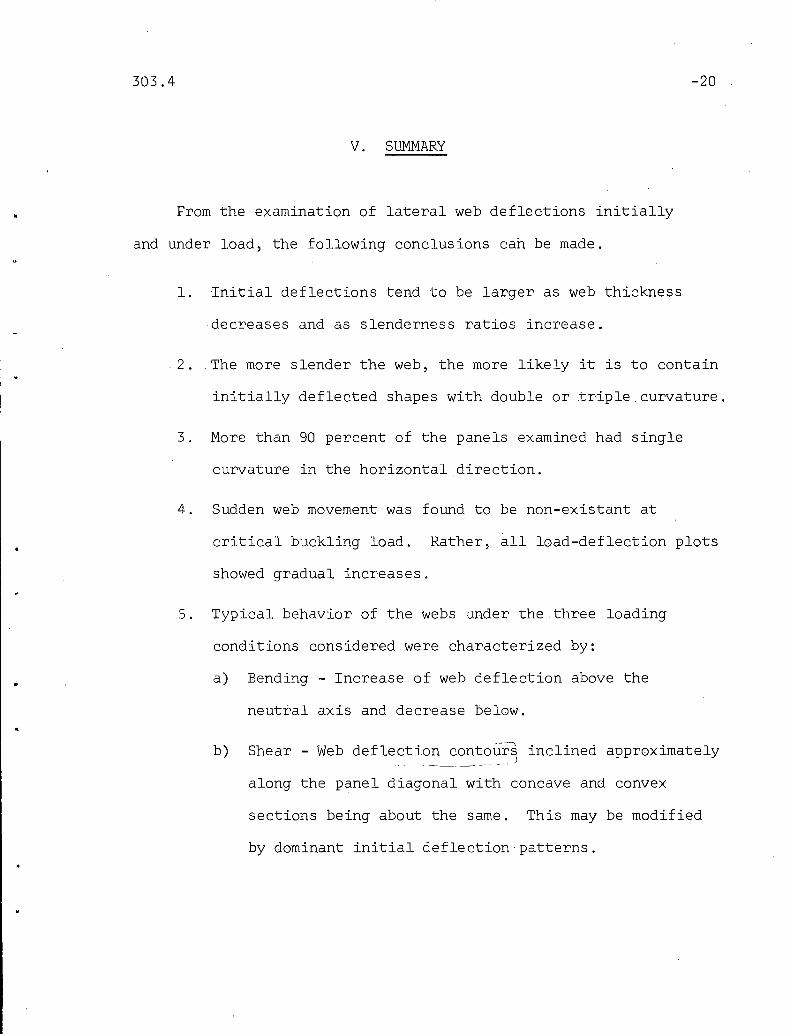
From the examination of lateral web deflections initially
and under load, the following conclusions can be made.
1. Initial deflections tend to be larger as web thickness
decreases ana as slenderness ratios increase .
. 2. The more slender the web, the more likely it is to contain
initially deflected shapes with double or triple curvature.
3. More than 90 percent of the panels examined had single
curvature in the horizontal direction.
4. Sudden web movement was found to be non-existant at
critical buckling load. Rather, all load-deflection plots
showed gradual increases.
5. Typical behavior of the webs under the three loading
conaitions considered were characterized by:
a) Bending - Increase of web deflection above the
neutral axis and decrease below.
b) Shear - Web deflection contours inclined approximatelyJ
along the panel diagonal with concave and convex
sections being about the same. This may be modified
by dominant initial deflection patterns.

303.4 -21
c) Combined Bending and Shear - Web deflection contours
similar to those under shear with the deflected
region above the neutral axis of greater magnitude
than that below.
This quantitative review of initial lateral web deflections
and qualitative examination of the corresponding deflections under
load gives future investigators experimental evidence as to the
behavior of slender webs of welded plate girders. It is anticipated
that this data will be used in determining stresses throughout the
webs of the test girders, including both membrane (axial) and plate
bending stresses. Once these stresses are known, another step in
the process of fully understanding girder behavior under static
and fatigue loadings will be completed.~
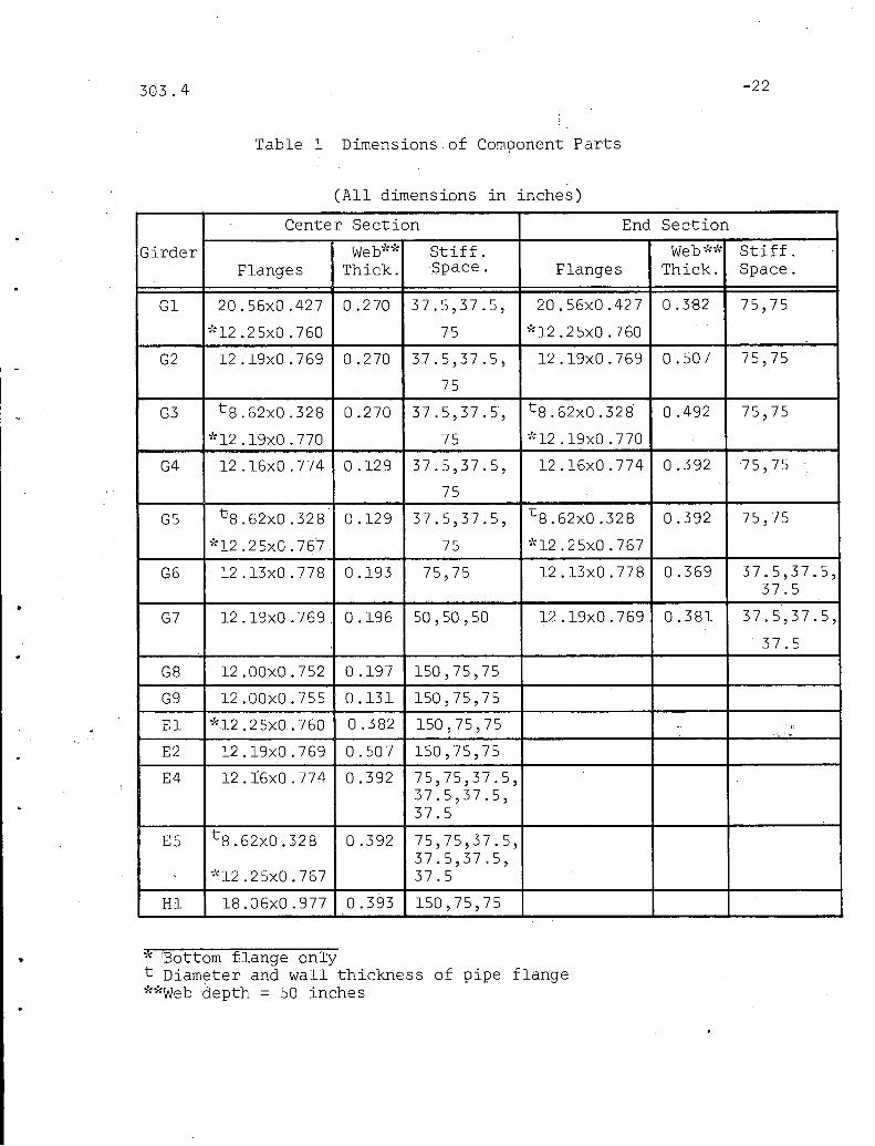
303.4 -22
Table 1 Dimensions,of Component Parts
(All dimensions in inches)
Center Section End Section
Girder Web~t:~\" Stiff. Web~':* Stiff.Flanges Thick. Space. Flanges Thick. Space.
G1 20.56xO.427 0.270 37.5,37.5, 20.56xO.427 0.3-82 75,75
~':12 .2 5xO .760 75 ~':12 .25xO. 760
G2 12 . 19xO .769 0.270 37.5,37.5, 12 .19xO .769 0.507 75,75
75
G3 t8.62xO.328 0.270 37.5,37.5, t8.62xO.328 0.492 75,75
~': 12 . 19xO .770 75 ~:12 .19xO .770
G4 12.16xO.774 0.129 37.5,37.5, 12 .16xO. 774 0.392 75,75
75
G5 t'8 .62xO .328 0.129 37.5,37.5, t8.62xO.328 0.392 75,75
~':12 .2 5xO .767 75 ~:12 .2 5xO .767
G6 12.13xO.778 0.193 75,75 12 .13xO .778 0.369 37.5,37.5,37.5
G7 12 . 19xO .769 _ 0.196 50,50,50 12.19xO.769 0.381 37.5,37.5,
37.5
G8 12.00xO.752 0.197 150,75,75
G9 12.00xO.755 0.131 150,75,75
El ~:12 .2 5xO. 760 0.. 382 150,75,75 "- ,-'.
E2 12 .19xO .769 0.507 150,75,75
E4 12.16xO.774 0.392 75,75,37.5,37.5,37.5,37.5
E5 t 8 . 62xO.328 0.392 75,75,37.5,37.5,37.5,
~':12 .2 5xO .767 37.5
H1 18.06xO.977 0.393 150,75,75
* 'Bottom flange onlyt Diameter and wall thickness of pipe flange~'d:Webdepth = 50 inches

303.4
Table 1 (Continued)
(All dimensions in inches)
~23
Center Section End Section
Girder Web-1d~ Stiff. WebId: Stiff.Flanges Thick. Space. Flanges Thick. Space.
H2 18.06x1.008 0.390 50,50,50, -i
25,25,25,25,25,25
Fl 12.04xO.998 0.189 75,75 12.04xO.998 0.389 40,4040
F2 12.00xO.998 0.190 50,50,50 12.00xO.998 0.389 40,40,40
F3 12.13x1.011 0.174 50,50,50 12 .13x1. 011 0.378 40,40,40
F4 12.07x1.008 0.192 50,50,50 12.29x1.636 0.312 120
F5 12.06x1.010 0.170 50,50,50 12 . 18x1. 646 0.312 120
F6 12 .13xO. 628 0.182 50,50,50 12.13xO.628 0.312 90
F7 12.15xO.638 00182 50,50,50 12 . 15xO .638 0.312 90
F8 12.00xO.708 0.203 50,50,60,~':18 .00x1.003 50,50
F9 12.00xO.708 0.195 50,50,60,-1:18.00xl.003 50,50
* Bottom flange only**Web depth = 50 inches

-24
Characteristic Loads of Test G" dTable 2 ,lr ers
p p p pcr u
Girder (kips)cr u
Q( ~ (kips) Girder Q( S (kips) (kips)
G1 1. 50 185 70.1 81 G8 3.00 254 41. 5 170
0.75 185 41. 9 72 1. 50 254 56.4 200
G2 1. 50 185 74.1 135 1.00 254 57.3 259
0.75 185 74.1 ' 144 G9 3.00 382 12.9 96
G3 1. 50 185 82.1 130 1. 50 382 16.8 150
0.75 185 82.1 136
G4 1. 50 388 15.3 118 . H1 3.00 127 377 1260
0.75 388 15.3 125 1. 50 127 464 1538
G5 1. 50 388 17 .0 110 H2 1.00 128 594 1834
0.75 388 17 .0 124 0.50 128 1614 2250
G6 1. 50 259 27.4 116 F1 1. 50 265 25.7 106
0.75 259 51. 9 150F2 1.00 263 34.3 131
0.50 259 97.6 177 F3 1.00 287 26.2 120
G7 1.00 255 37.6 140 0.80 132 298 240
£1 3.00 131 332 555 F4 1.00 260 35.4 127
1. 50 131 402 5802.40 160 98 169
1.00 131 506 684 F5 1.00 294 24.6 111
£2 3.00 99 570 755 2.40 160 98 169
1. 50 99 584 757 F6 1.00 275 43.8 144
£4 1. 50 128 445 595 1. 80 160 94.5 162
0.75 128 513 634 F7 1.00 275 44.4 139
0.50 128 517 645 1. 80 160 95.0 158
£5 0.36 128 314 350 F8 1.20 246 68.7 179
0.75 128 322 360 1.00 246 36.2 173
1.00 246 27.3 179
F9 1.20' 256 63.1 178
1.00 256 32.4 165
1.00 256 24.7 123

I •
I: ~,
I •
303.4 -25
Table 3 Example of Web Deflection'Data
Girder G7; Station x = 0 inches; Readings in inches
Y( in.) Ref. Load 1 (Ok) Load 2 (27k
) Load 3 ( 54k )
Read. Diff. Read. Diff. Read. Diff.
+21 0.532 0.560 +0.028 0.562 +0.030 0.568 +0.036
+15 0.554 0.590 +0.036 0.594 +0.040 0.611 +0.057
+9 0.590 0.580 -0.010 0.587 -0.003 0.504 -0.086
0 0.516 0.438 -0.078 0.448 -0.068 0.436 -0.080
-9 0.571 0.480 -0.091 0.488 -0.083 0.461 -0.110
-15 0.511 0.448 -0.063 0.452 -0.059 0.435 ~0.076
"
-21 0.512 0.494 -0.018 0.495 -0.017 0.490 -0.022

.303.4
Table 4 Maximum Initial Lateral Deflections ofTest Girders
-26
p
Girderw. w.
10 5w.
13l max l max l max
Q'(in) xWeb depth t
Gl 1. 50 185 0.141 71 0.467\
0.75 185 0.054 27 0.196
0.75 185 0.033 17 0.122
G2 1. 50 185 0.157 79 0.581
1. 50 99 0.067 34 0.132
1. 50 99 0.076 38 0.150
0.75 185 0.080 40 0.296
0.75 185, 0.067 34 0.248
G3 1. 50 185 0.160 80 0.593
1. 50 102 0.115 58 0.080
1. 50 102 0.234 117 0.181
0.75 185 0.097 49 0.359
0.75 185 0.101 51 0.374
G4 1. 50 388 0.278 139 2.155
1. 50 128 0.044 22 0.122
1. 50 128 0.076 38 0.194
0.75 388 0.160 80 1.240
0.75 388 0.108 54 0.837
G5 1. 50 388 0.456 228 3,535
1. 50 128 0.144 72 0.367
1. 50 128 0.063 32 0.161
0.75 388 0.243 122 1. 884
0.75 388 0.204 102 1. 581
G6 1. 50 259 0.448 224 2.321
1. 50 259 0.221 111 1.145
G7 1.00 255 0.358 179 1.826
1.00 255 0.133 67 0.678
1.00 255 0.309 155 1. 576

303.4 -27
Table 4 (Continued)
w. w.105
w.Girder Q' 13
1 max 1 max 1 max(in) Web Depth x t
G7 0.80 131 0.021 11 0.0550.'_-
0.80 131 0.092 46 0.241
G8 3.00 254 0.297 149 1. 507
1. 50 254 0.122 61 0.619
G9 3.00 382 0.474 237 3.618
1. 50 382 0.455, 228 3.473
1. 50 382 0.450 ,225 3.435
El 3.00 131 0.320 160 0.838.
1. 50 131 0.073 37 0.191
1. 50 131 0.098 49 0.257
E2 3.00 99 .0.041 21 0.081
1. 50 99 0.101 51 0.199
E4 1. 50 128 ,0.112 52 0.286
0.75 128 0.067 34 0.171
0.75 128 0.102 51 0.260
0.75 128 0.055 28 0.140
E5 1. 50 128 0.169 85 0.431
0.75 128 0.020 10 0.051
HI 3.00 127 0.261 131 0.664
1. 50 127 0.199 100 0.506
1. 50 127 0.105 53 0.181
H2 1.00 128 0.134 67 0.344
1.00 128 0.195 98 0.500
1.00 128 0.036 18 0.092
0.50 128 0.105 53 0.269
0.50 128 0.057 ; 28 0.146I
0.50 128 0.049 25 0.125
0.50 128 0.067 34 0.172
0.50 128 0.032 16 0.082
0.50 128 0.184 92 0.472

303.4 -28
Table 4 (Continued)
Girder w. w.10 5
w.1 max .1 max x 1 max
Q' 13 (in) Web Depth t
Fl 1. 50 264 0.608 304 3.217
1. 50 264 0.493 247 2.609
0.80 129 0.134 67 0.344
0.80 129 0.108 54 0.277
0.80 129 0.123 62 . 0.316
0.80 129 0.149 75 0.383
0.80 129 0.066 33 0.169
0.80 129 0.103 52 0.264
F2 1. 00 263 0.206 103 1.084
1.00 263 0.191 96 1.005
1.00 263 0.053 27 0.394
0.80 129 0.037 19 0.095
0.80 129 0.022 11 0.057
0.80 129 0.016 8 0.041
0.80 129 0.030 15 0.021
0.80 129 0.058 29 0.149
0.80 129 0.040 20 0.103
F3 1.00 .288 0.255 128 1.465
1.00 288 0.150 75 0.860
1.00 288 0.135 68 0.776
0.80 132 0.185 93 0.489
0.80 132 0.129 65 0.341
0.80 132 0.085 43 0.224
0.80 132 0.101 51 0.267
0.80 132 0.042 21 0.111
0.80 132 0.050 .25 0.133

303.4 -29
Table 4 (Continued)
Girder w. w.10 5 w.
i3l max l max x l max
Q'( in) Web· Depth t
F4 2.40 160 0.171 86 0.548
2.40 160 0.102 51 0.327
1.00 260 0.208 104 1.083
1.00 260 0.161 81 0.838
1.00 260 0.142 71 0.739
. F5 2.40 160 0.185 93 0.593
2.40 160 0.033 17 0.106
1.00 294 0.131 66 0.771
1.00 294 0.101 51 0.594
1.00 294 0.171 86 1.006
F6 1. 80 160 0.197 99 0.631
1.80 160 0.149· 75 0.478
1.00 274 0.253 127 1.390
1.00 274 0.184 92 1,011
1.00 274 0.279 140 1. 533
F7 1. 80 160 0.104 52 0.333
1. 80 160 0.108 54 0.346
1.00 275 0.362 181 1.989
1.00 275 0.191 96 1.049
.1.00 275 0.280 140 1. 538
F8 2.40 246 0.111 56 0.547
1.00 246 0.159 80 0.784
1.00 246 0.170 85 0.836
1.00 246 0.059 30 0.291
1.00 246 0.082 41 0.404
F9 2.40 256 0.200 100 1.025
1.00 256 0.113 57 0.580
1.00 256 0.153 77 0.785
1.00 256 0.059 30 0.302
1.00 256 0.128 64 0.656

•
LNoLN
.. ~I~ iilo ... ", :ol.
d" ""~ r::lf1i
I ~ Iw
I~I iT
Girders GI,G28G4 I q IGI 20~' 7lr~ I
Sym. Aboutll... ExceptI G2,G4 12",%~ = Stiffener Lett of Center ~ =
~11"GI,G4 3~ WEB ," \ GI,G2 ~~ GI G2 0"
IGI,G~,~
CUT FROM G2 ~ WEB ~GI,G2:11 WEB
G4~~G4 1/16" G2 Ye
~G4~ WEB
1~-
AM412" x34 I ~
~I I I" IriPn rri'lL "" "
I I12'-6"
ILNo
I Iti- I
IG38G5 I Is , sJm. About II.. Except
~I /B" PIPE (0.322" WALL)Sti fener Left
lof Center
---------- -------- -l, -- --- ---
G3 ~ WEBI - -\ ~" G3 O'~
\ G5~,CUT FROM
~G3~ WEB G3 16 ~ G~~
G5~'WEB 121'F50G5~ WEB G5~2
~/2"
/3" 3" 12"'~41~ ~
3'-I~~ I"8' 6'-3" 6-3 21~911 I'-d 3'-1~ 6'-311 I~d 21-911 6 1-3 11 6'-3" f;'
15'-9" 141-611 15-'-9"
46'-0"
r4-
l
Girder
Fig. 1 Specimens and Loading Condition,Girders Gl-GS

15"x~ "Girder E4 0; ,8 ~
)2"x3~"
r 11 I! \!4- I!11 14
CUT .F;~M G43/~ WEB ,I 4" ~" 4"x ~4"" ~12IfF ,I 3 .11 Ir-----'-
4'-2" ~ i'N/-- V16...h..
"~
v
lI,
1~""'I I"'I ~1 Ji. ,- :i
7-f-lI \:2"x3~" Sym, About t. Except ~h b
~ ~
15"x\"For Transverse Stiffeners
6,1 I 19,,19,,1I
II
I 3'-1 ~2" I I
16'6'-3" 6'-3" 3'-1/2" 3~ I~" 3~1/2",I 27'~6,,1
, ,
Typical also for Girders EI, E2,E5, G8 a G9
IShear Diagram t.
iL--~~~~-V=Y.=2P==LJJ _Il v= ~2P I
. Moment Diagram
I --'-' ::::::"""
IlJ-JI-'
Fig. 2 Specimens and Loading Condition,Girders El-ES, G8-G9

1I
~Sym. Above <t Except
IZ"xl'~ IZ"xIV4'~ ""("F Bearing o~ Stiffners
V 5"1" V3''x~4''!~ ~x Yz l!(Typ) (Typ.)
3/a" Web 3/16" Web
~ r Z"
~ "
~I ~~ '~
IZ"x I.!!./" IZ"xI V4--' ",,\, ...
6' 3'-4" 3'-411 3'-4" 3'-0" 9" 4'-211 4'-2 11 4'- 21• 9" 3'-0" 3'-411 3'_4 11 3'-4" 6'
13'-3" I 14'-6" I 13'-3"
41'-0" ._---,
Girder F 3
LL
v = PShear Diagram
I
v = - P
Moment Diagram1
IZOP (kip-in.) ILNN
Fig. 3 Specimens and Loading Condition,Girders G6 & G7, Fl-F5

LNoLN
r.. ..r-IS"xl" ~17"xl" GIRDER H2 t ~TYP'~Typ.
II
.X1"--/
C\l
I-s12"xl" f--- s"x~" 50"x3;s" WEB ~,I
;,.p. Typ. Typ. Typ.
A IS"XI"J '-17"XI" JJ-10"1 3@ 4'-2" 10" 5 @ 2'-1" 110"
I -"27'-7"
17"Ty
SOTH ENDS3
rIS"XI" r I7"XI" ~o ~s 17" GIRDER HI Typ. Typ. Typ.~s Typ.
I
'- 5"x3/s"xs" .I"~ " 1
M"
C\l~S~2"xl· 50" x ~s" WEB s"x 3/S" e=trTyp.
,;,.
TYR
IS"xl" 17"xl"----""
10" 5'-3" 5'·3" 10" 5'-3" 5'·3" 10"
7'-0" 13'·5" 7'·0"
17"xTyp
Fig. 4 Specimens and Loading Condition,Girders Hl &- H2
ILNLN

LNoLN
ppI
~12"x5/~'~ Sym. A'bout Cl
3"XV4'I
'" I.i, I\-'\ I~ "- r
~5"XV2'~ r (TypJ ~
Iv v
(Typ.)Ya" I~ I\-- /1 ~I V V v
5" W bI
"'l ........
~6 e 3,( Web~I\- 14 "16
i / v / v
~ ~ 12" ~ 5"------1" I
I 11'-3,,1~
~. 7'-6" 1'-3" 4'-2" 4'-2" 4'-2" 7'-6" ~
31'-0"
GIRDERS F6 a F7
'f4'-2"
L
SHEAR DIAGRAMI
v=p
v=p
MOMENT DIAGRAM
90 P (kip-in). M ILN.po
Fig. 5 Specimens and Loading Condition,Girders F6 & F7

LNoLN
ISym About ~r" lP
......---12 x 1Y,6 ~12 X 11 3/ a
\ Ya ~v
,3 x ~4I
Va ~" ,5 x ~2 /3XY4~ ~5 x Y2
I V3/16 Web I
~
CD @8
@ (j)® ® I r ®~
I I'----18 x I ~
6,j 25" 50" 50" 13" 60" 13" 50" 50" 25" /6'
29'-0"
r50
L
Fig. 6 Specimens and Loading Condition,Girders F8 and F9
Il:NUl

303.4 -36
Fig. 7 Dial Gage Rig for Web Deflection Measurements

303.4 -37
~I:
+21- '\\+15 - .
\+9 - \./ .1·
0-
I'II11
~11
:i
\ ./\ ./ .II· I
~..
./ \\ \ \\ +65'14 \ +1023/4\ f+121
"'\ \
,
//I\\
It \2 •
rr. III, .
IIIIIIIIII'III11I,II
4IIII
"Scale: l...--..-J w=0.5 inches t=0.131 inches
Fig. 8 Initia~ Web Deflection Shapes, Singleand Double Curvature (Girder G9)
o
+9
-+15
• 21\..\./
• - -15
U=C:::::::=::::I=c::::!:=-~5=0==== C=::!::::::::I_~=:I;2~:UScale: 1...-----1
1 w=O.5 inches . t=O.129 inches
Fig. 9 Initial Web Deflection Shapes,Triple Curvature (Girder G4)

-:---------------------------11 • '.
Wi max.t
LNoLN
3.90
3.60
3.30
3.00
2.70
Web depth = 50 in. .
t =O.l29in. to 0.510 in.
• Single Curvature
o . ·Dooble Curvature
6. Triple Curvature
•
•~o
f3
2AO
2.10
1.80
1.50
1.20
090
060
030
0___.
•• ••
i••••••,.•
100 120 140 160
•
•0
0
• 6-
• <9 6-• 6-
6.
6-0 • 6-•• •• 06- 6.6-
•• • 6-
•• 0•\•
180 200 220 240 260 280 300 320 340 360 380 400I
LNco
Fig. 10 Maximum Initial Deflection VersusWeb Slenderness Ratio

Wi max.t
3.60
3.30
3.00
2.70
2.40
2.10
Web depth = 50 in.
t =0.129 in. to 0.510 in.
• Single Curvature
o Double Curvature
I::. Triple Curvature
•
•
•
1.80
1.50
1.20
0.90
0.60
030
o
0,-'; I::.•
c9 I::.I::. •• I::.
I::.
0 • I::.•• • I::.
• 0 1::. •I::. 1::.1::.
• , -I::. ••• •• • •il
0 •• ••• • •
100 120140 160 180 200 220 240 260 280 300 320 340 360 380 400Larger Panel Dimension
t
Fig. 11 Maximum Initial Deflection VersusLargest Panel Dimension
ILNill

Wi max.
t
3.6 ••:3.30 •3.00 Web depth = 50 inches
2.70
•, •-, •• •I •• I.,•
0.25 0.30 0.35 0.45 0.50
Web Thickness (inches) I.j::>0
,0.20
••
••
, ••• •
• •...• •• ••• ••• •
•
0.15
•
•
•
•
•
OL.-__---I. ---L. ....L... .L...-_~__l__~!::....1... _L_ ...L__
0.10
1.50
1.80
1.20
2.40
2.10
0.60
0.90
0.30
Fig. 12 Maximum Initial Deflection Versus Web Thickness

303.4
........--:_:::.:..--=-::--~.03 -../" .;....:....-====:--=---O~-- ...................,,/''''/~,.;::------..:-- .....~ ..............'.......... ......,
I / /" / " ..... -----.... .......15........ .....,..........", I I I I / ,--__ -_ " , ..... "I I I I I 1/,,----_- ......2'..... .............., " , \, , , " ( III ,-... -_, -_, " ... " " \ \'I (I II I '. "', '" \ \I , ' , III ( .27 \." \ '\ \ \I I : I ( : ' , (" \ 1 \ \ 1 \ \ \ II:, I I1 11/ ..35 \ I I I "'I \ I I111111::1; (j j I Irl'lI II' \ \ I \1 I I I I / J' I I II I II \ \ I, \J / / ./ / I' I I I111\\\\\ / / I / I', I I111\\\'\ / ,/,,/ I ./ (I, II , 1 \ \ \ ' , __/ _'" I ,/ ;; ,1 ," II I \ \ \ \ \ ", I ;-' /; , I II , , \ \ \ \ / II I ...,-- , I ,, \ \ \ \ \ \,1 II ./ ". , ( , I
\ I '\ \ \ \ \ I "'''' II ... ..;. ,.1 I I II \ \ \ \ "/1/ ;1 / / I I\ \ " " ,,'.._ ,," ,,""/1"---__ / / I\ \ \ " ,-_ : ""./ ..... ,;...-..... ---_/ / /\ ... \,~, ' .._ ;".... --- - .............- // /
.............~==-.:::::~_....... ----.....=::- ..............
(0)
//-:.---- lJ ,-;:~-...../ (" -------------,- '\ \I I _-.----------,-'\ \ II \ (- , I)\ \ .'-_ 09 --_ I I.\ '- -------'. ......... / I" ---- .06 ------/11
.....-------:03 -------- ......."
(b)
SINGLE
Girder G7Panel I
DOUBLE
Girder F6Panel I
-41
0_-=====:9.·0~3=======-_-",
o
.,.,. -- - - .._--------- ........
.....-' ------- "/" -- ....., '\\ \ ---.06 _/ \
'............. I'-----.03 -----_.. "" I, /
' ...- .....
.00(c)
o
TRIPLE
Girder F9Panel 3
Fig. 13 Initial Web Deflection Contours
l.Nol.N
y
122V
, I-V + Vi +"i = X+ I-I
0.5
o.2::--;;;;;~~~~'~J ± -o +1 +Z
X=-ta-. lEer I
---:±_- ---.J._ OD·5=-=--=-~---:.-------- -',-- -02- - -"'""'"" - -Y:=IO --0.5- '-,
I . - __ ...:..._ ........ ~ )
.... , \.,&
Fig. 14 Lateral Deflection Versus AppliedStrain From Ref. 12

303.4
:'r (= E:r )6
5
4
2
o
F7
•
•
2 ,3
-43
4 wt
Fig. 15 Load-Deflection Curves for Panels in Bending

303.4 -44
6
5
wt
432
.F5 G7
. <3 //.. FIl;r3e/· .
•
}
e i I y'-'., .•
Ie i ell1 \
o
2
3
4
Fig. 16 Load-Deflection Curves for Panels in Shear
,
303.4
P-Per
-45
(: E:r
)
6
5
4
F9F9
:3
2
o
•FS Fsi
2 :3 4 wt
Fig. 17 Load-Deflection Curves for Panels Subjectedto Combined Bending and High Shear

303.4 -46
o
=C:::::'=====)
- -15
-+15
--+9
--+21
I --
i~~1/1 I 'II ii 13
I 5913
1/1.
I~ f• •
-25 -12~4
:W
G4
- -- -
Scole: I I W =0.5 in.5 = 0.129 in. Legend:
1= 05 =29% Pu9 =58 %Pu13 =86 % Pu
•
Fig. 18 Sequence of Web Deflection Growth,Girder G4, Panel 2

303.4 -47
/-'.........._~-------::~-===-~:===-- ,I .-06 ,,""'",..".._---__-_ , \I ,........ "."'''' ,,,,. ---- ,\I I ............ .,,/ ,,,...........12,,-,---_--=-. ,',\
I --,/';,/'" _--_ " \ \I I / / ..... ' '" _.18........._:---- "<'\' \\: ' /~/ "./ ;';<;2-'_--_::::.::<>~,\\\\\I I ----"" / I .......... / ........../",.30 ---........', ,'\\\11
I ( (( I / I I \" \ ,\ \ 1\I I f I' I I I I ' ......----- _ .... \, \ 1""'\11\I II I I \ \ I , I \ II II I' I \ \ , I I \ 'IIII'I II I \ \ \ \ '.... J I 111111
I \," '.... / ' , /1111\1\ " " ,,'...... - ~----- ,,/ , '/I'II, -_................ -_------- ,./1,/'1I ------ -- ,---- --------" II'
I , ----.. ........-.::--__-:..-.:---:..=:-=-~:::=~_/~' II'
I \ ..- :-----=-=====::::...--...... /'!I \ / ----------- -~ 'I1\ /' ......-------------- :::--.../,
\\~~//Cg,j
,,-, ----------I ' .... _---.03 --_--------::.----.... ,'/,.........' ---- ------_ - \I, ......----- _.09--.:------- , \" "",...,,- ....-,-- .",..------.::.' , ,\'1 ... - ..... """ ..... ",'" .... .15 .....------ ,'\''I I --, ,," ,,;' "," _--- __ ,::-' ,. \ \ \II' /;';' /.21 _----_ , .... ,' 1\1I , / / / /" -.... , , 1'\1I', (/ / 1,/ ,27 ----, '\\ I \1
1,1\
I' , I I I I \' , \ \ I 1 \1II I I \ ,\ \ " \ I \ \ 11111I I ", \ ,'.... ) I \ \ , '1 I
'I \ \"," ----~ 1\ 1"1 11I \ ' ,'............. I I 1"1 I III __...;..... - - ----:;:. ,,111,'I' -_................... - ----- /111\ _ ...... - ----------- .... I',-_ ----.::::::.::-=--===-=-----..:j ,'I1\ ;' ---------_--------_ IIII \ // ------------O::=--===~ -~ I,'\ / ..... ....._, ,
\/'~~,j
(0) P=O ( b) PF:::l30%P u
o
Gradual Change of Deflection Contours,Girder F7, Panel 3
Fig. 19-
(c) PF:::l60%P u (d) PF:::l 90%Pu

'. -'
LNoVI.:po
• I
U =c::::::::i==-=-==!!:::::=t =====c::==~2~C=:=:::::II======~C==:!:::=t=-====~=c::::::!==a=~==i=c::=!::+:::::II621'21JScole: L------I" W =0.5 inches
- p=OKLegend
- P=72K t =0.129 inches
Fig. 20 Deflected Cross-Sectional Shapes UnderBending, Girder G5
I:p.co

,
u
.I..II..II
1.
•,i•,•
\\.I. .
1/.
•-25
'.
~\ - <21-/ /') i j / i ii• - +15 _. • I· ,. i··! - +9 -I I i / J .. I I
I \/ \ i \! \! il: - 0-'\ \, \\ \\ \\
- -15-. .- •• •• .-
-12'/2 +12 Y2 1+25 +37Y2 +50 +62~2:LJ.
VJoVJ• I
.p.
Scole: w =0.5 inches Legend:-- p=OK
K-- P=54t=0.27 inches
Fig. 21 Deflected Cross-Sectional Shapes UnderBending, Girder Gl
I.p.lD

303.4
Fig. 22 Overall View of Girder Gl
-50

303.4 -51
---------.,.,. ---"",--- ------ -.... ........../'" ".---------... .................... "
I I' ./ _-------_--- __ ......... "I I "", ----- - .................. ,I 1 -- --- - , \I I"'" ------- ' \\ 1, I ( ""," _-----.::::- " \.', \ \, \ /..... . '\, \\, \' \ I I ..... _.;-----" \,\ \ \I \ \\ \ \ \ ( , - - - I \ , I \ , I I
\ \ \, ,"-_ ':27_ -,)..... / "'/"..",,, I J J J, '" ' "21 -- -"",,, '" ./\ \ ". - -- ::::_" ""'" /' ,.. / / I\ "' ..... '- ~./ "..\, ' ..... 15 - - - - - -".. /' /' "" /\ \ ' ..... ' .. ' ----_ ..... ".,:::" .....,..,,"',,'"\ --"'...-",..",\ ' 09'- _...-- - - ...-'-' - ...-", '....... . ....- ----.-.- ...- ..-::--...- --'__-----1
" ...... _- -------"",-"'..... "'3 - - - _ .... :-~:::::::....--'--------..A"I __ ..-
1-- - 0
p =Okips
(a)
o
p =94 kips
". - -----~=-:.. -=----=--=--- ~/ ",---:. ----------.....""".-... -..... ......
/, ,. " - - - - - - - - -~---::..--- -- "1// "'-------:--- -- '\,./ ..... --- ----- ---_.... "
1 1 //1 " ---------.::::- -:- ", \ \I ,.. -- -- ...... , -,I J 1('" /"-:.._-::_-_~ ,,,,,\,\\\I I { I I I I ,."'",'/ __ ..... -;_ - :::-" ~ ,,\ \ \ \ \ \ \ \",,',(1 {( ,." /- ",'\\\\'\11,I \ I ,I \ \ \ \ ,,'-.... ':36 _)/ )) / ) , I 11/ I\\\\\,'':::' ......... ----= ~"'/"'/I//\
'
\ \' " ,' __ --:30... _ -" "", -:::.'" '" /1 I I\ ' -- /" / I
\ \ ,,',' ---24--:...::--" ",-./ /1 I /, . -- "'"..\ \" ,,,<._------- '" ./ I 1\ \" - -:18- - - -:. - - ...... ",/ I\ \ " " ..... ,--------_ ./ /
" " 12 - - - - - '"\ " ' --. -.... --::---:-- ...." ................ ...... -~- .----::-. -- - -, .....- -.06'-;-~-:..:~::::::~;::=::::~-1,------- ~
(b)
Fig. 23 Web Deflection Contours, Girder F6, Panel 3

303.4
~--------- - - - ..../ ~---- ~. /,,"'7 ----__"
I ,/ " ....... ------- ...., .... \ \
'I { \ J J\ \, .... ' / I, " '.09 _ - ~ /,,---- ,... ' ..... , _....... /
" ....... - -------....",'~03-----~=---- --
------:.03--------
(a)
(b)
P = Okips
P =67.5 kips
-52
Fig. 24 Web Deflection Contours, Girder F8, Panel 2

303.4 -53
p =0 kipso---0
o..... ,
\\
\\II
---
..... .....-
"" --~/ " .... ---- ...... _--, " .....
I /,/ ..... ----""I / ", .......... --...... ......
I ...........- " "II" - '"I I / I " .... -- ..... , ,
1 11/'" '" \I I" '", I I I I I /-.... , \ ,
I \ I I \', \21.... ) I I I1\\', '\. / } I1\\\'" "/\ \ \' " ....... - ...... "
\ ' "\ \ \ \. .............15 --'"\ \ \ . --\ \ ,\ \\ \\ \ ----\ , .,.. ...... ',. ........
\ ....... - ---- 03- - '- - - --...... --..._----. ---.",..,.
(a)
...
p= 54 kips
(b)
Fig. 25 Web Deflection Contours, Girder G6, Panel 1

303.4 -54
F~g. 26 Shear Deflection Patterns, Girder El

303.4
.-- - - -----or ...- ------ - .....'" '" --- -- .....
'" or or '" -- --- "--- ........I I' or --- ..... "'" - "-I I' -- ..... .....( / /' --, -- ...... , '\
I( I I I , ,
\ \I I " \
I \I , \ \ \ \ \\ I I J I \ l\ I \ \ \15 J I
'\. J I ) J\. ','''' -- - '" -...-,," ,09' ." -- ./ / ..... /""" "",. ..... - - - - .- - ,,;
...-" ,,---- "",., / p= o kips':03 ..... - __ - - - - ---..... --
0----
(a)
-55
(b)
P =67.5kips
Fig. 27 Web Deflection Contours, Girder F8, Panel 3

..
..
303.4
o
o
~----o
(a)
~.~~,.' .,.----,;,..- .....:::---06 \
",/,~ ','..."/' ----, ., \
","''/ ~- ,\ I_ ......:::-"',;: _--.12 - ... \ II
........,- "'.... , - I I I"'''', ,'1/1/" '\ ...."'" "'/ 1
'" I I .... ~.... '" II I \ ,--- " .... // ,r ( , -""'....", /\' ,----- "",- / 0, ............ , ",."".""'" --_ttl'" -----_.... ",...... .... ........._---._--_........
{b}
P=Okips
P=67.5kips
-56
Fig. 28 Web Deflection Contours, Girder F8, Panel 5

-57
I -p=o • -p=o \-p=o- P =26% P. i - P =36
% ft i-p = 49% PuuI \\• • ••
, :; ~ , 1\• • ••
I ~ J /II • • • ..
\\ II II•, • II•, .
F3 11 + 180F3 • - 220 (in.) -140 F4
-p=ou.~P =49% Pu\\••
\ \iI• •II••II••
F4 ! +210
•;-p=oD-P= 43% Pu/I..II••
\\••\\•
"F5 -210
IIIl -p=o, - P ='43% P.u••
/I
/I\i\\..\\•\ .
F,5 • -180
; -p=o 1/ -P=O -P=O• ••"
- P = 65~/oPu II - P =65% P' ~-P =65% P.
Ii•• u •• u
/1 \\• • • • • •
/1 I ,Scale: I\
• • • • • •
I \ \ \ ,W =0.5 in•r I
• • • • • •
• - \ \ \\ /I• • • •\ , , II
\'..
'"F6·· -123 3/4 F6\ +135 F7 -155
Fig. 29 Initial and Deflected Cross-SectionalShapes of End Panels

...
303.4
1.
2.
3.
4.
5.
6.
7.
8.
9.
-58
REFERENCES
K. Basler, B. T. Yen, J. A. Mueller and B. ThurlimannWEB BUCKLING TESTS ON WELDED PLATE GIRDERS,Bulletin No. 64, Welding Research Council, NewYork, September, 1960
K. Basler and B. ThurlimannSTRENGTH OF PLATE GIRDERS IN BENDING, Proceedings,ASCE, Vol. 87, No. ST6, August 1961
K. BaslerSTRENGTH OF PLATE GIRDERS IN SHEAR, Proceedings,ASCE, Vol. 87, No. ST7, October, 1961
K. BaslerSTRENGTH OF PLATE GIRDERS UNDER COMBINED BENDINGAND SHEAR, Proceedings, ASCE, Vol. 87, No. ST7,October, 1961
Kihara, Watanabe, Masubuchi and SatohRESEARCHES ON WELDING STRESS AND SHRINKAGE DISTORTIONIN JAPAN, Society of Naval Architects of Japan,Dai-Nippon Printing Co., Ltd.,. Tokyo, Japan
P. B. Cooper, H. S. Lew and B. T. YenTESTS ON WELDED HIGH STRENGTH STEEL PLATE GIRBERSSUBJECTED TO SHEAR, Lehigh University, FritzEngineering Laboratory Report No. 251.29, December,1962
B. T. Yen and P. B. CooperFATIGUE TESTS OF WELDED PLATE GIRDERS, FritzEngineerirtg Laboratory Report No. 251.26, LehighUniversity, February, 1962
B. T. Yen and J. A. MuellerFATIGUE TESTS OF WELDED PLATE GIRDERS IN SHEAR, FritzEngineering Laboratory Report No. 303.6, LehighUniversity, November, 1964
J. A. Corrado, J. A. Mueller and B. T. YenFATIGUE TESTS OF WELDED PLATE GIRDERS IN BENDING,
. Fritz Engineering Laboratory Report No. 303.9,Lehigh University, May, 1965

I ~
303.4
10.
11.
12.
13.
14.
15.
16.
17.
-59
STANDARD SPECIFICATIONS FOR WELDED HIGHWAY ANDRAILWAY BRIDGES, American Welding Society,New York, 1963
S. Timoshenko and S. Woinowsky-KriegerTHEORY OF PLATES AND SHELLS, McGraw-Hill BookCompany, New York, 1959
B. T. YenON THE FA~IGUE STRENGTH OF WELDED PLATE GIRDERS,Fritz Engineering Laboratory Report No. 303.1,Lehigh University, November, 1963
G. Wastlund and St. BergmanBUCKLING OF WEBS IN:DEEP STEEL I-GIRBERS, IABSE,Publications, No.8, p. 291, 1947
K. C. RockeyPLATE GIRDER DESIGN, Engineering (London), No. 185,p. 788, December 20, 1957
Taylor, Vasishth, Yuan an8 VasarhelyiAN EXPERIMENTAL INVESTIGATION OF THE BEHAVIOR OF ARIVETED PLATE GIRDER WITH A THIN WEB, Private Communication, Dept. of Civil Engrg., Univ. of Washington,Seattle, August 1959
L. R. Hall and J. E. StallmeyerTHIN WEB GIRDER FATIGUE BEHAVIOR AS INFLUENCED BYBOUNDARY RIGIDITY, Univ. of Illinois, StructuralResearch Series No. 278, January 1964
A. A. TopracFATIGUE STRENGTH OF HYBRID PLATE GIRDERS, StructuresFatigue Research Laboratory Report No. 04-64, Univ.of Texas, July 1965

303.4
VITA
-60
The author was born in El.Paso, .Texas, Decembe.r 3,. 1942, the
first child of Elizabeth (Sweney) andWilliam.Dudley.
He was graduated from. Council Rock High .School in Newtown,
Pennsylvania, in June 1960. In·September 1960 he enrolled at the
Virginia Military Institute, Lexington,. Virginia and in June 1964
received the degree of Bachelor of Science in Civil Engineering.
Awarded a Research Assistantship in Civil Engineering at Fritz
Engineering Laboratory, Lehigh Univers.ity, Bethlehem, .. Pennsy.lvania,
the author began studies for a Master's Degree in September,. 1964,
and has been assocated throughout with the research. concerning the
fatigu~ strength of welded plate girders.


