1
Load Pull Overview
X-Parameters with
Active and Hybrid Active
Load Pull Gary Simpson, CTO
Maury Microwave
EuMW 2012
www.maurymw.com

2
Load Pull Overview
General
Load Pull Overview
3
Load Pull Overview
1. Introduction to Maury Microwave
2. Basics and Benefits of Load Pull
3. Pulsed Measurements
4. Harmonic Load Pull
5. Active Tuning
6. Load Pull with X-Parameters
7. Ultra-Fast Noise Parameters
8. Summary
Outline

4
Load Pull Overview
Maury Microwave Corporation
Headquarters
2900 Inland Empire Blvd, Ontario California, USA

5
Load Pull Overview
• 1957 Incorporated in California
• Experts in Precision Machining for Microwave Components
• 1980’s Aligned with HP/Agilent to provide ALL 8510 Cal Kits
• 1987 World’s First Commercial Automated Load Pull and Noise Parameter System
• 2004 Launched LSNA (Large Signal Network Analyzer)
• 2008 Load Pull with X-Params
• 2008 Ultra-Fast Noise Params*
*Patent Pending
6
Load Pull Overview
AS9100 & ISO 9001
CE Conformance
ANSI/NCSL Z540-1
MIL-STD-45662A
Traceability to NIST (National Institute of Standards & Technology)
Certification, Conformance, Accountability

7
Load Pull Overview
Space Flight Applications • One Piece Flange and Body
• No Braze Joints
• No Dielectric Versions For
High Radiation Requirements
• Optimized Tuning
8
Load Pull Overview
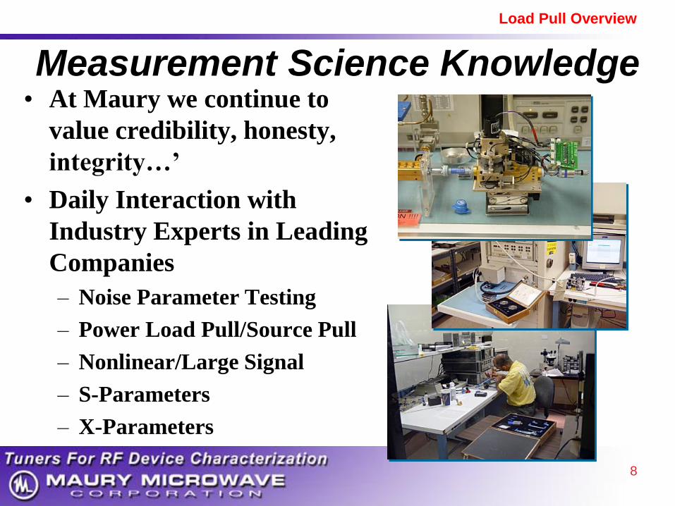
Measurement Science Knowledge • At Maury we continue to
value credibility, honesty,
integrity…’
• Daily Interaction with
Industry Experts in Leading
Companies
– Noise Parameter Testing
– Power Load Pull/Source Pull
– Nonlinear/Large Signal
– S-Parameters
– X-Parameters

9
Load Pull Overview
Experts In
Full System
Integration
Solutions • Experienced Technical
Team
– Waveguide & Coaxial
– Turnkey & Customized
Solutions

10
Load Pull Overview
Maury Product Overview
Device Characterization
Components

11
Load Pull Overview
Market Leader Device Characterization
Emphasis in Automated
Impedance Control
• USB Controlled Tuners
• Software - Automated Measurements
• Load Pull & Source Pull
• Large-Signal / Nonlinear
Measurements
• Noise Parameter Measurements
• Agilent Global Channel Partner*

12
Load Pull Overview
What is a Tuner?
A device to control impedance
Reflection Control Method:
• Magnitude – move probe up / down
• Phase – move probe horizontally
Mismatch probe in
a 50-Ohm slab line USB Interface
Side View
Probe
Probe
End View
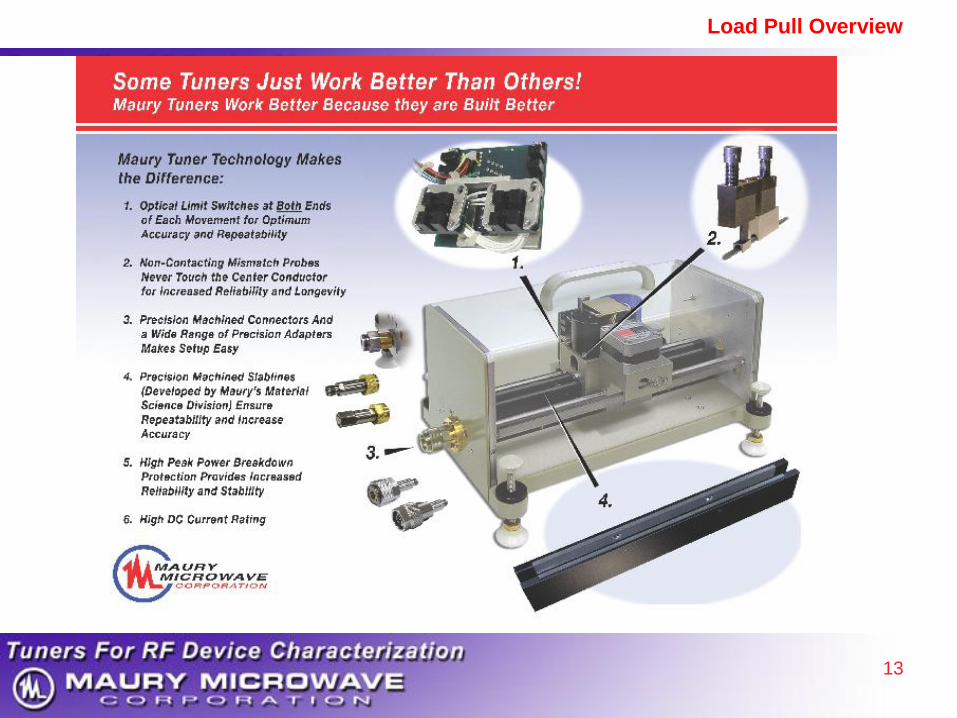
13
Load Pull Overview

14
Load Pull Overview
Automated
Mechanical Tuners
0.25 – 110 GHz
Coaxial and Waveguide
Repeatability > 40 or 50 dB
USB Control
ATS software or DLL
Reliable and proven technology
More than 20 years in Tuner Technology

15
Load Pull Overview
1. Introduction to Maury Microwave
2. Basics and Benefits of Load Pull
3. Pulsed Measurements
4. Harmonic Load Pull
5. Active Tuning
6. Load Pull with X-Parameters
7. Ultra-Fast Noise Parameters
8. Summary
Outline

16
Load Pull Overview
What Is Load Pull?
Measurement vs.
Impedance

17
Load Pull Overview
What is Load Pull
TUNER
TUNER
source Load
Stimulus and
Measurement
DUT

18
Load Pull Overview
Why Load Pull? • Characterize Non-Linear Devices
– Small Signal S-Parameters Not Sufficient
– Must Measure with Actual Operating Conditions
– Most Power Devices are Far from 50 Ohms
• Stability / Ruggedness Test – Linear or Non-Linear Device
– Test at High Reflection, All Phases
• Characterize Noise Parameters – Measure vs. Source Impedance
– Load Match Optional - to Reduce Uncertainty

19
Load Pull Overview
Benefits of Load Pull
• See impedance matching trade-offs
– Allows design to specs
– Faster time to market, Eliminate cut-and-try
• Develop High-Efficiency Power Amps
• Test Stability under any mismatch
– S-parameters not accurate for large-signal Osc.
• Test Ruggedness – Improve Reliability
– Avoid amplifier degradation or failure
20
Load Pull Overview
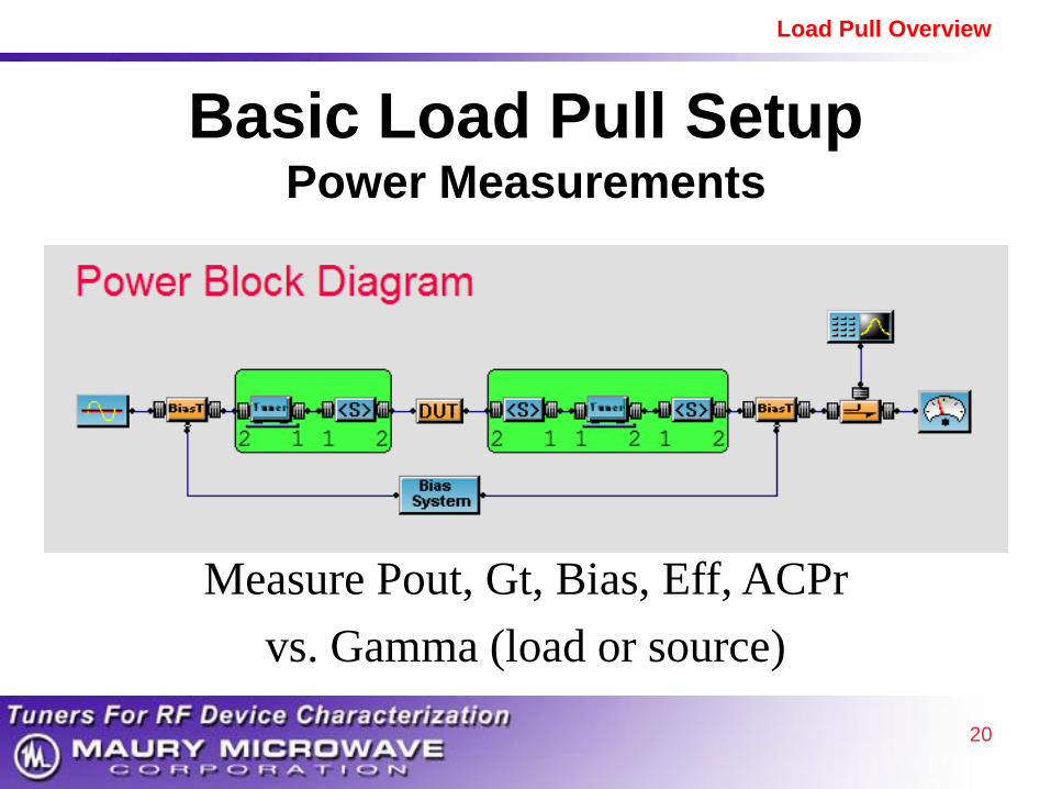
Basic Load Pull Setup
Power Measurements
Measure Pout, Gt, Bias, Eff, ACPr
vs. Gamma (load or source)
21
Load Pull Overview
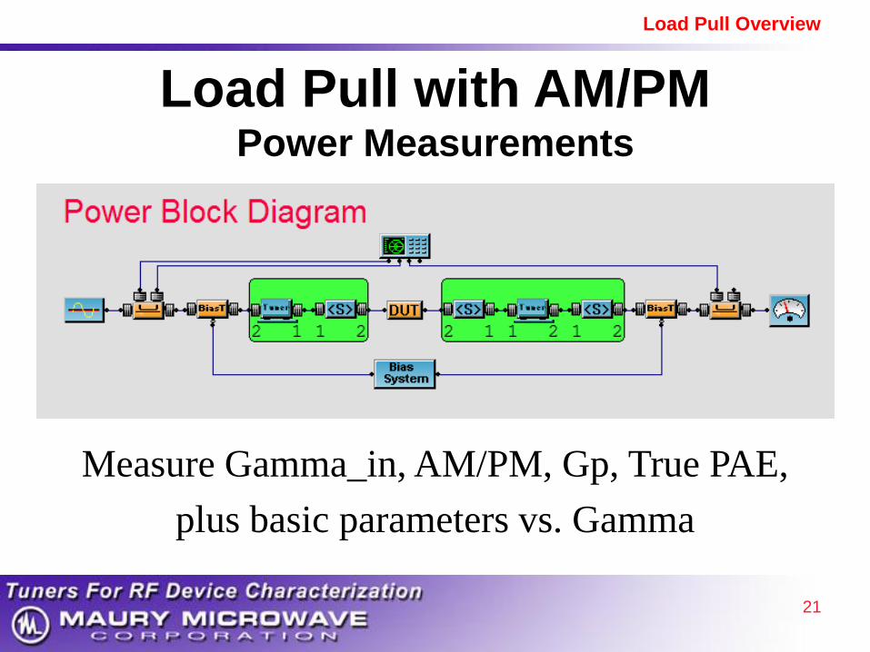
Load Pull with AM/PM Power Measurements
Measure Gamma_in, AM/PM, Gp, True PAE,
plus basic parameters vs. Gamma
22
Load Pull Overview
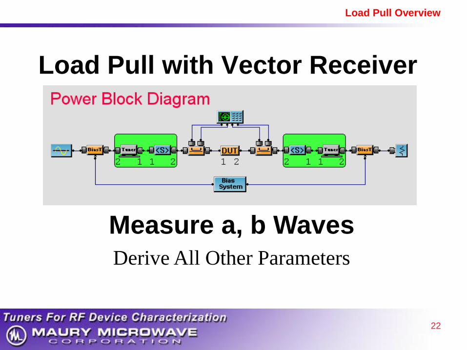
Load Pull with Vector Receiver
Measure a, b Waves
Derive All Other Parameters
23
Load Pull Overview
Load Pull Stimulus • Measure vs. Gamma (load or source)
• Measure vs. Power
• Measure vs. Bias
• Measure vs. Frequency
• Sweep Plan: Measure vs. All Variables
– Result is Multi-Dimensional Data Covering
Complete Region of Operation

24
Load Pull Overview
Typical Measured Parameters
• Pout, Gain, Bias, Efficiency
• Linearity
– ACPr, EVM, AM/PM, Intermodulation ...
• Spurious Signals , in, Waveforms...
• ATS Software Version 5
– 76 Built-in Parameters
– 25 User Defined Parameters
25
Load Pull Overview
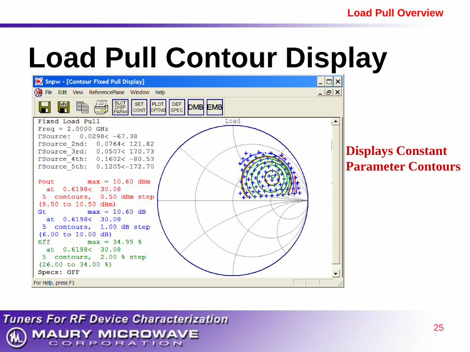
Displays Constant
Parameter Contours
Load Pull Contour Display

26
Load Pull Overview
On-Wafer Load Pull

27
Load Pull Overview
1. Introduction to Maury Microwave
2. Basics and Benefits of Load Pull
3. Pulsed Measurements
4. Harmonic Load Pull
5. Active Tuning
6. Load Pull with X-Parameters
7. Ultra-Fast Noise Parameters
8. Summary
Outline

28
Load Pull Overview
Pulsed IV measurements
Several quiescent bias point
Short pulse : Quasi-isothermal conditions
Low duty cycle : Constant mean temperature
Quiescent bias point : Thermal conditions fixed

29
Load Pull Overview
Pulsed S-Parameters

30
Load Pull Overview
Pulsed IV & S parameter measurements
Synchronization between Pulse IV and Measurements
31
Load Pull Overview
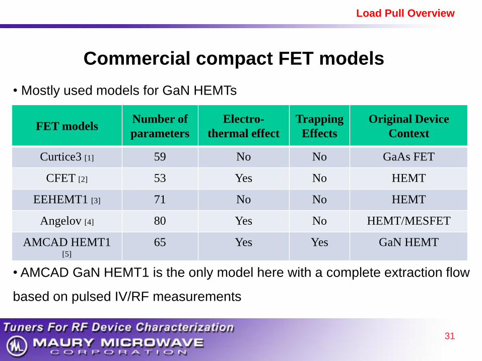
Commercial compact FET models
• Mostly used models for GaN HEMTs
FET models
Number of
parameters
Electro-
thermal effect
Trapping
Effects
Original Device
Context
Curtice3 [1] 59 No No GaAs FET
CFET [2] 53 Yes No HEMT
EEHEMT1 [3] 71 No No HEMT
Angelov [4] 80 Yes No HEMT/MESFET
AMCAD HEMT1 [5]
65 Yes Yes GaN HEMT
• AMCAD GaN HEMT1 is the only model here with a complete extraction flow
based on pulsed IV/RF measurements

32
Load Pull Overview
Pulsed Bias/RF Load Pull Power Measurements
TUNER Coupler
Power Sensor
Power Sensor
WA Attenuators
Coupler
Spectrum
Analyzer
Power Meter
Signal Generator
TUNER
Pulsed System
33
Load Pull Overview
1. Introduction to Maury Microwave
2. Basics and Benefits of Load Pull
3. Pulsed Measurements
4. Harmonic Load Pull
5. Active Tuning
6. Load Pull with X-Parameters
7. Ultra-Fast Noise Parameters
8. Summary
Outline
34
Load Pull Overview
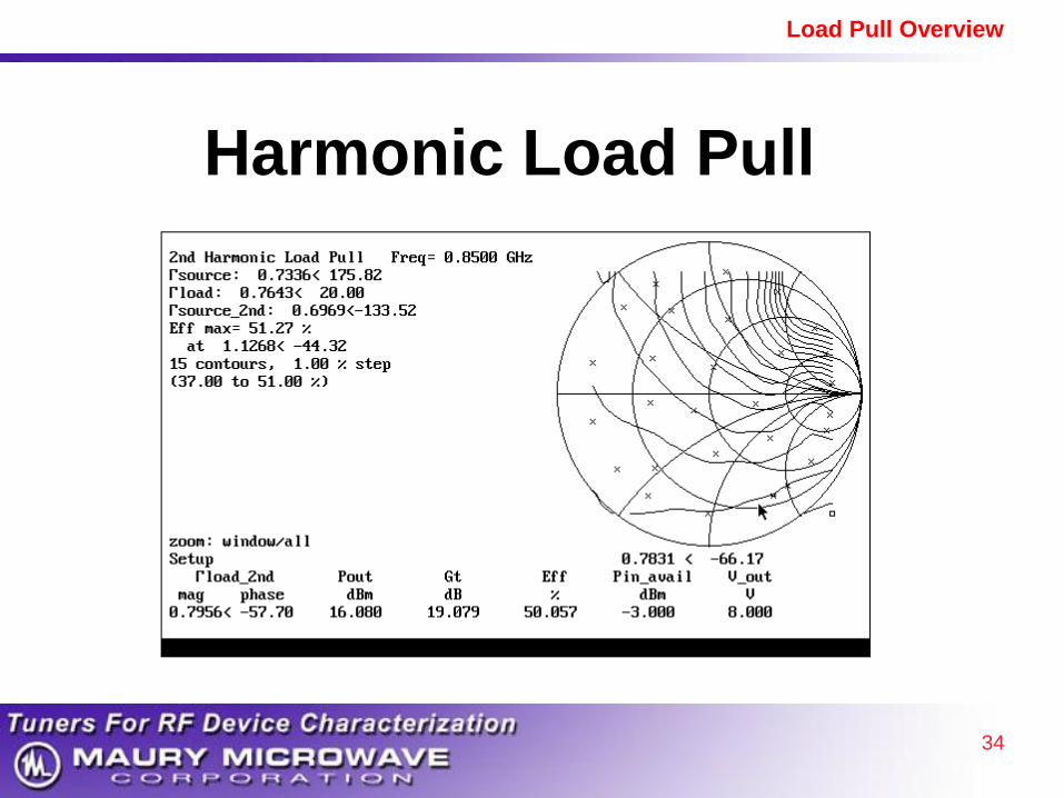
Harmonic Load Pull

35
Load Pull Overview
Harmonic Load Pull
• Multiplexer Method
• Cascaded Tuner Method
• Active Tuning Method

36
Load Pull Overview
RF
Source
Tuner
F1
DUT
Load
Load
Power
Meter
Tuner
F1
Tuner
F2
Tuner
F3
T
R
I
P
L
E
X
E
R
Separate Fundamental / Harmonics with Filters
Harmonic Load Pull Multiplexer Method

37
Load Pull Overview
Harmonic Load Pull Cascaded Tuner Method
RF
Source
Tuner
F1
Tuner
F1,2,3
Tuner
F1,2,3
Power
Meter
DUT
Select combination of tuner states
to simultaneously set F1, F2, F3
Tuner
F1,2,3

38
Load Pull Overview
1. Introduction to Maury Microwave
2. Basics and Benefits of Load Pull
3. Pulsed Measurements
4. Harmonic Load Pull
5. Active Tuning
6. Load Pull with X-Parameters
7. Ultra-Fast Noise Parameters
8. Summary
Outline
39
Load Pull Overview
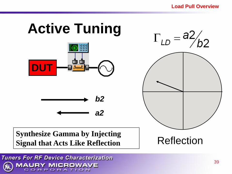
Active Tuning
Reflection
DUT
b2
a2
Synthesize Gamma by Injecting
Signal that Acts Like Reflection
40
Load Pull Overview
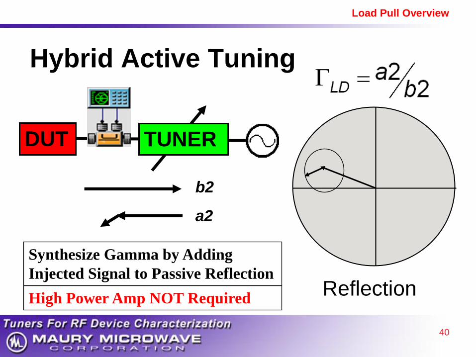
Hybrid Active Tuning
Reflection
DUT
TUNER
b2
a2
Synthesize Gamma by Adding
Injected Signal to Passive Reflection
High Power Amp NOT Required

41
Load Pull Overview
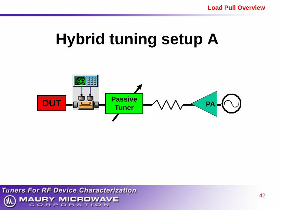
Hybrid Setup Passive + Active Tuning
• Passive Tuner Reflects Most F1 Power
• Eliminates Very High Power Amp
42
Load Pull Overview
Hybrid tuning setup A
DUT
Passive
Tuner PA

43
Load Pull Overview
DUT
Passive
Tuner
PA
F2
F1
Hybrid tuning setup B

44
Load Pull Overview
DUT
Passive
Tuner
PA
Hybrid tuning setup C

45
Load Pull Overview
DUT
Active tuning with the PNA-X
PNA-X
PA
F1
F2
F3
a1 b1 a2 b2

46
Load Pull Overview
DUT
Active tuning with X-Parameters
PNA-X
PA
F1
Extraction
Signal
a1 b1 a2 b2
PA
Drive
Signal Port 1 Port 3

47
Load Pull Overview
DUT
Hybrid tuning with the PNA-X
PNA-X
PA
F1
F2
F3
Passive
Tuner
Passive
Tuner
a1 b1 a2 b2
48
Load Pull Overview
Easy Upgrade
With Vector Receiver Load Pull
• Add One Source per Harmonic
• With PNA-X, Use Built-in Source

49
Load Pull Overview
Active Load Pull
Benefits:
• Simple (with Vector Receiver)
• Can Achieve Gamma = 1 or greater
• Overcome Fixture Losses
• Higher Gamma at Fundamental
• Independent Harmonic Tuning
• Accuracy based on single VNA cal
• Economical – Add-on to Existing ATS
50
Load Pull Overview
1. Introduction to Maury Microwave
2. Basics and Benefits of Load Pull
3. Pulsed Measurements
4. Harmonic Load Pull
5. Active Tuning
6. Load Pull with X-Parameters
7. Ultra-Fast Noise Parameters
8. Summary
Outline

51
Load Pull Overview
New Paradigm for PA Design
• Instant Large Signal Model
• Major Breakthrough – Dream of Microwave Engineers for years
Solution:
Load Pull + NVNA + ADS
52
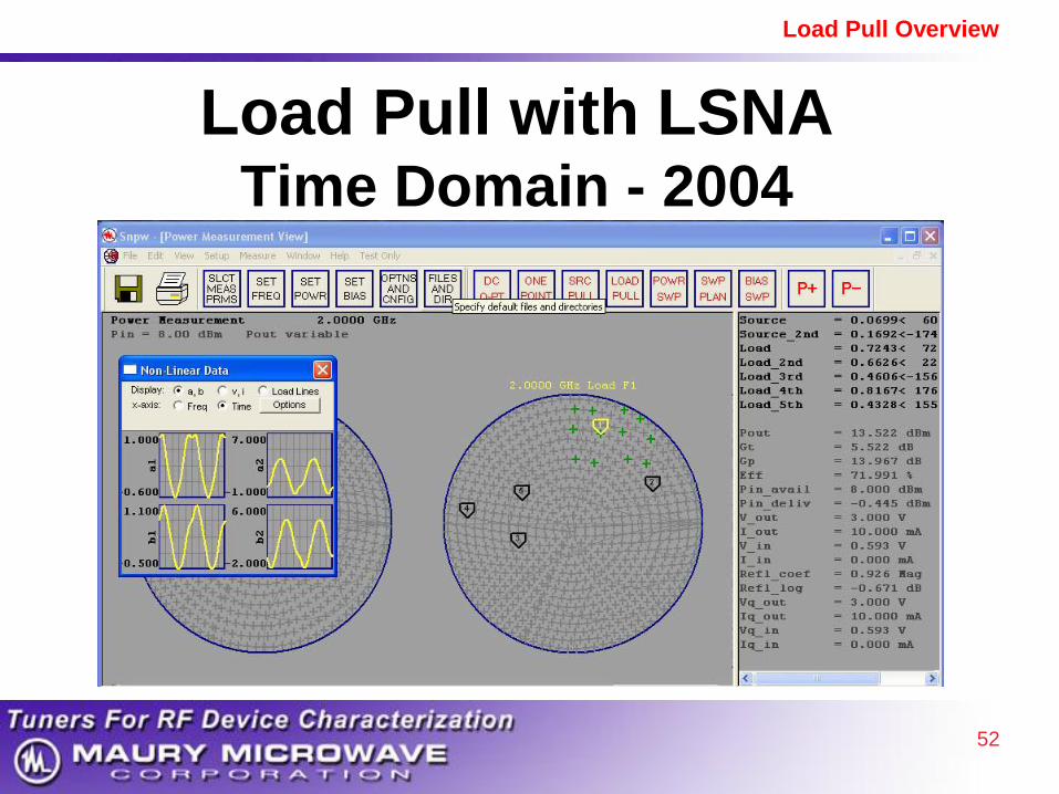
Load Pull Overview
Load Pull with LSNA Time Domain - 2004
53
Load Pull Overview
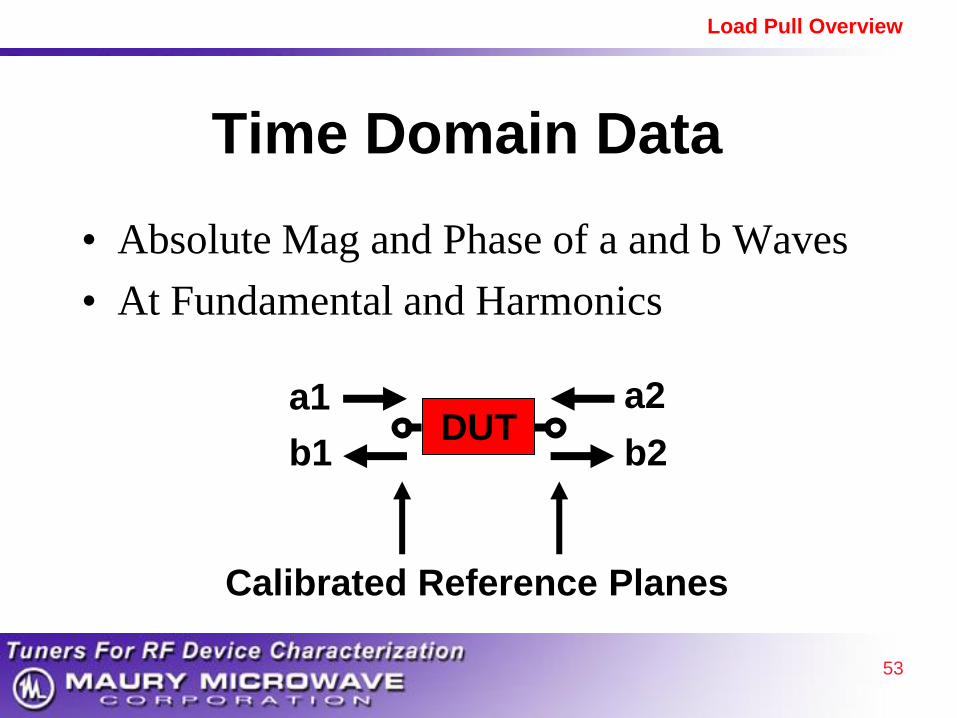
Time Domain Data
• Absolute Mag and Phase of a and b Waves
• At Fundamental and Harmonics
DUT a2
b2
a1
b1
Calibrated Reference Planes

54
Load Pull Overview
NVNA - 2008
• “Nonlinear Vector Network Analyzer
• Superset of LSNA
– “Large Signal Network Analyzer”
– Measures Time Domain
• Measures Time Domain and X-Parameters
– X-Parameters are Unique to Agilent NVNA
– X-Parameters act as Large Signal Model

55
Load Pull Overview
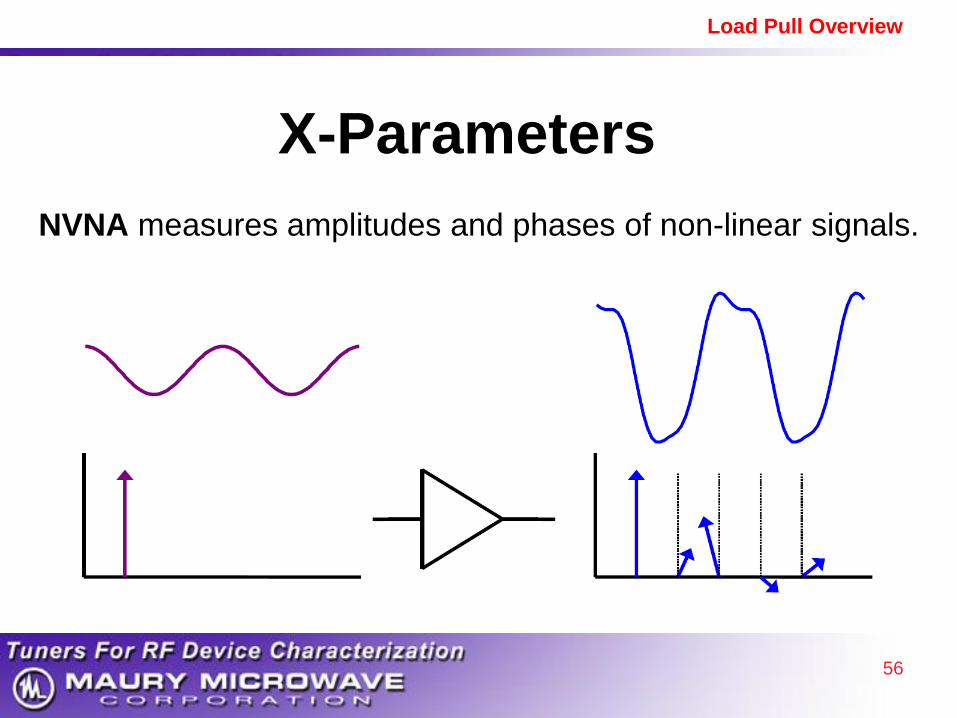
S-Parameters
VNA measures amplitudes and phases of Linear signals.
56
Load Pull Overview
X-Parameters
NVNA measures amplitudes and phases of non-linear signals.

57
Load Pull Overview
X-Parameter Summary
• Non-Linear Generalization of S-Parameters – S-Parameters are special case where distortion = 0
• Data covers one Large Signal Operating Point
• Acts like Large Signal, Non-Linear Model – In Region near Large Signal Operating Point
58
Load Pull Overview
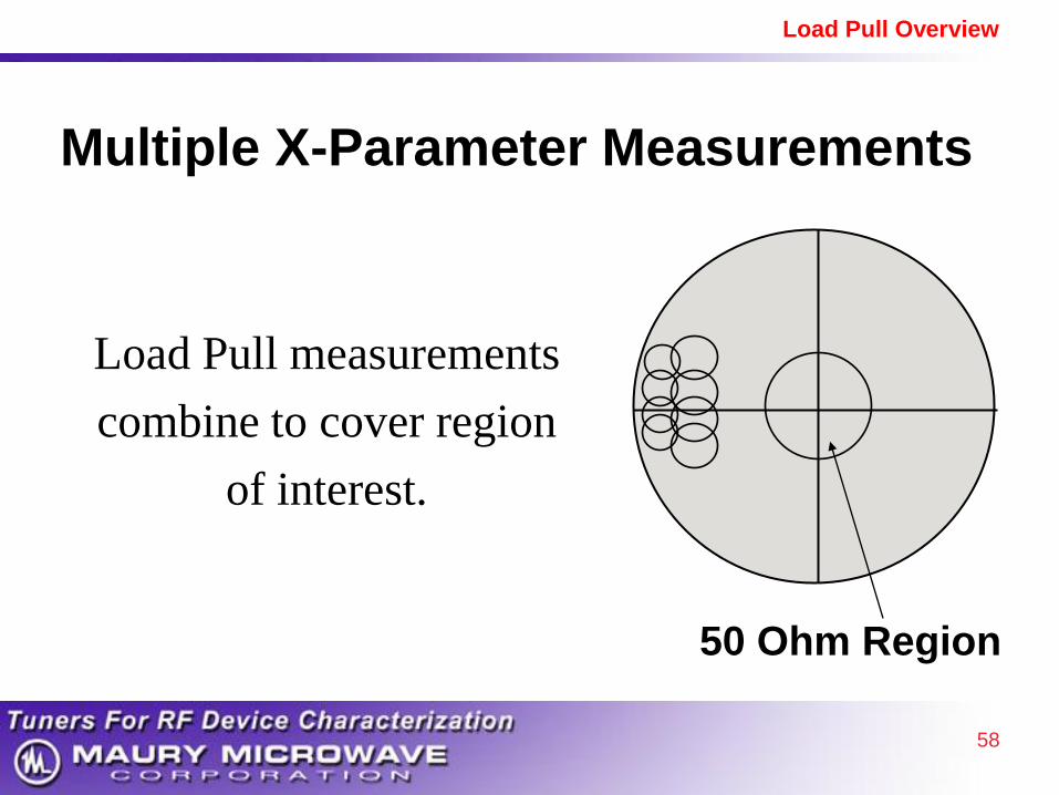
Multiple X-Parameter Measurements
Load Pull measurements
combine to cover region
of interest.
50 Ohm Region
59
Load Pull Overview
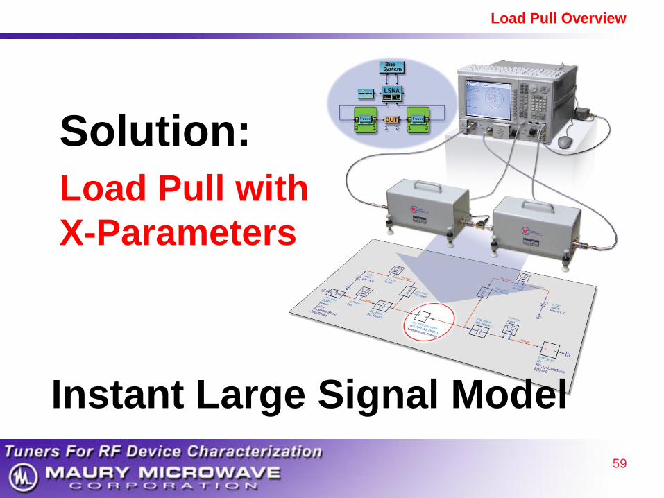
Solution:
Load Pull with
X-Parameters
Instant Large Signal Model
60
Load Pull Overview
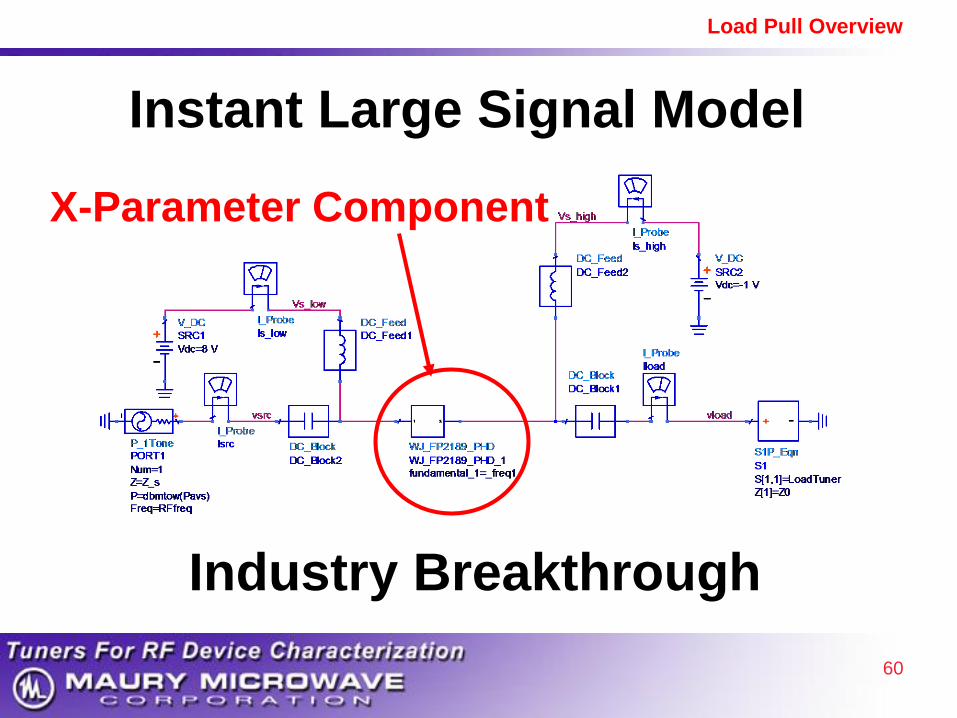
X-Parameter Component
Instant Large Signal Model
Industry Breakthrough
61
Load Pull Overview
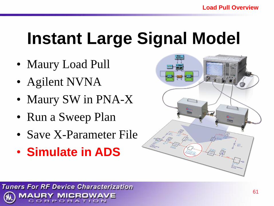
Instant Large Signal Model
• Maury Load Pull
• Agilent NVNA
• Maury SW in PNA-X
• Run a Sweep Plan
• Save X-Parameter File
• Simulate in ADS
62
Load Pull Overview
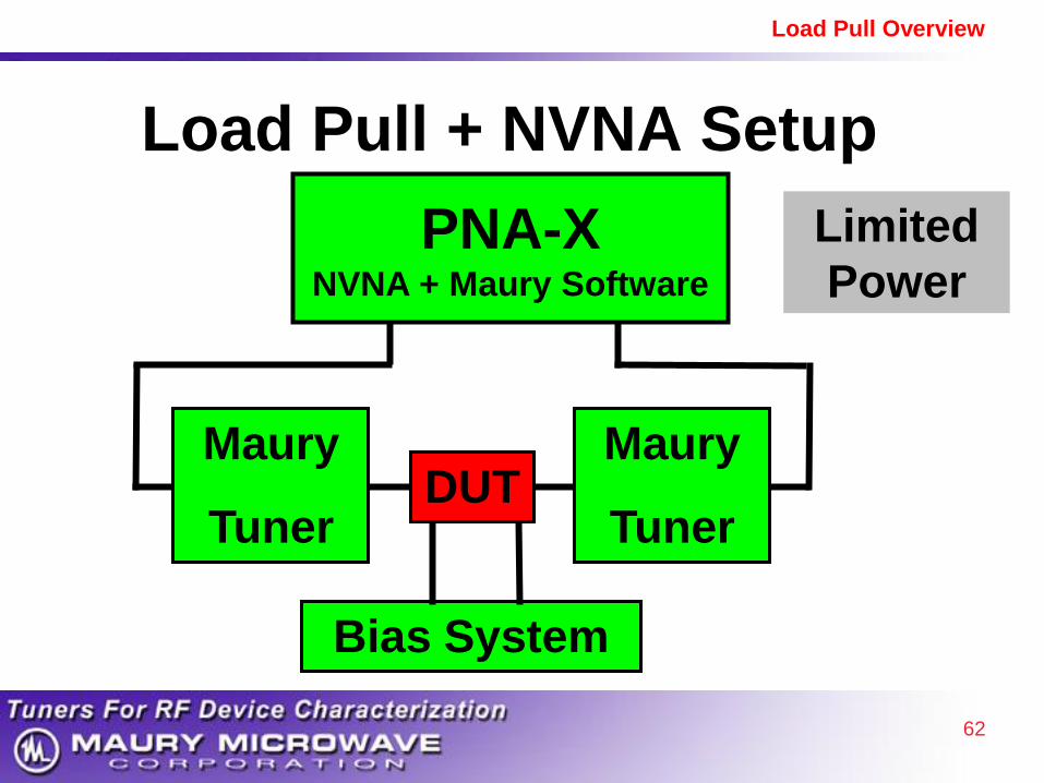
Load Pull + NVNA Setup
PNA-X NVNA + Maury Software
Maury
Tuner
Maury
Tuner DUT
Bias System
Limited
Power
63
Load Pull Overview
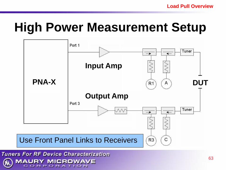
High Power Measurement Setup
PNA-X DUT
Input Amp
Output Amp
Use Front Panel Links to Receivers
64
Load Pull Overview
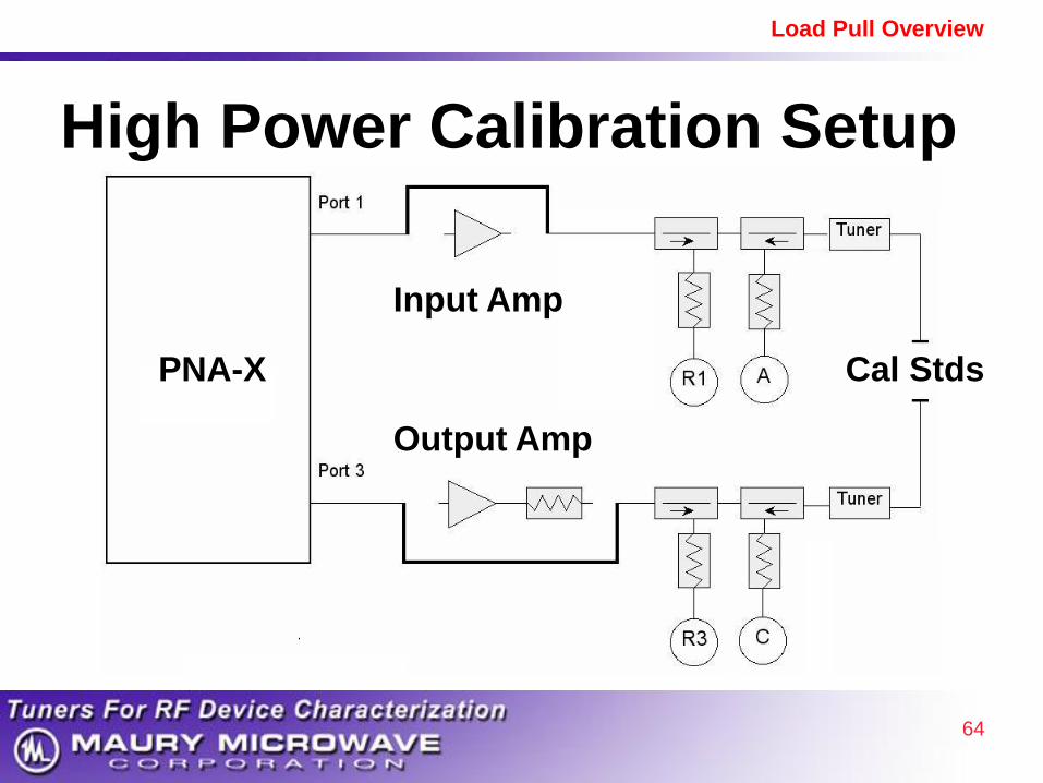
High Power Calibration Setup
PNA-X Cal Stds
Input Amp
Output Amp
65
Load Pull Overview
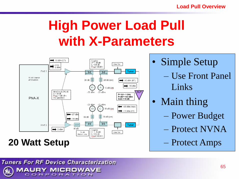
• Simple Setup
– Use Front Panel
Links
• Main thing
– Power Budget
– Protect NVNA
– Protect Amps
High Power Load Pull
with X-Parameters
20 Watt Setup

66
Load Pull Overview
Traditional Large Signal Model
• Use Small Signal and DC measurements
– Fit Model Parameters to Data
– Time-Consuming
– Accuracy Limited in Some Regions of Operation
– Technology Dependent
– Model is Extrapolated to Large Signal
• Load Pull is Accuracy Reference
– Load Pull is Measured at Actual Large Signal
67
Load Pull Overview
X-Parameter Large Signal Model
• Based on Large Signal Measurements
of X-Parameter Data
• Technology Independent
• Hides Design Details of Device
• Load Pull Sweep Plan for PA Design
New Paradigm for Modeling and Design

68
Load Pull Overview
Comparison of Models
Traditional • Circuit-based Model
• Time consuming
• Extrapolate to Large Signal
• Can relate to Physics
• Can be Scalable
X-Parameters
• Behavioral Model
• Instant Model
• Large Signal Directly
New Paradigm for PA
Modeling and Design
69
Load Pull Overview
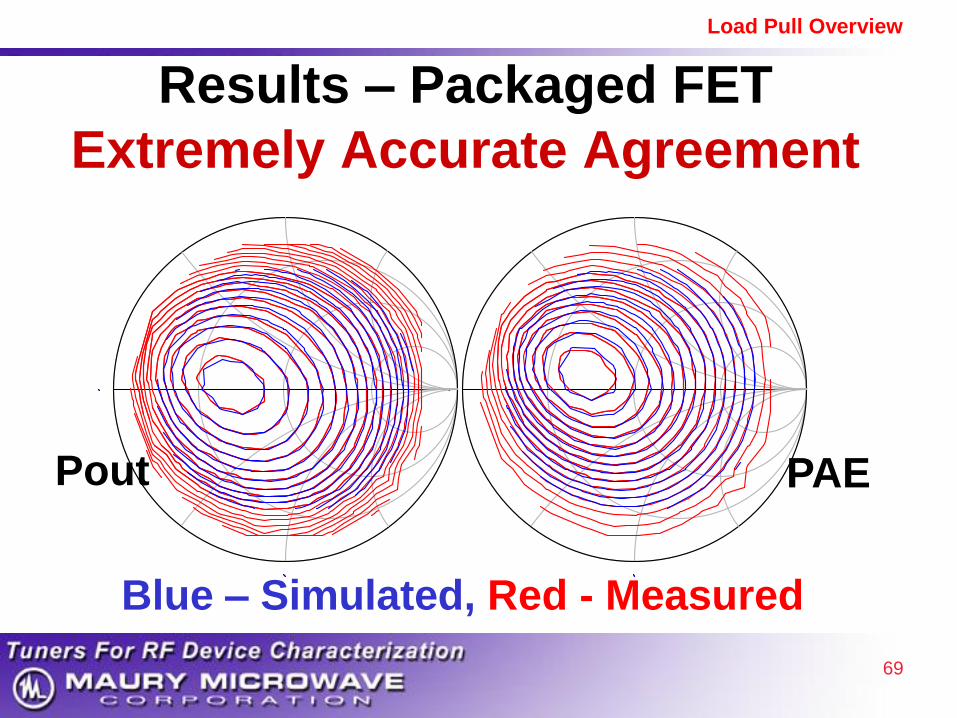
Results – Packaged FET Extremely Accurate Agreement
Pout PAE
Blue – Simulated, Red - Measured
70
Load Pull Overview
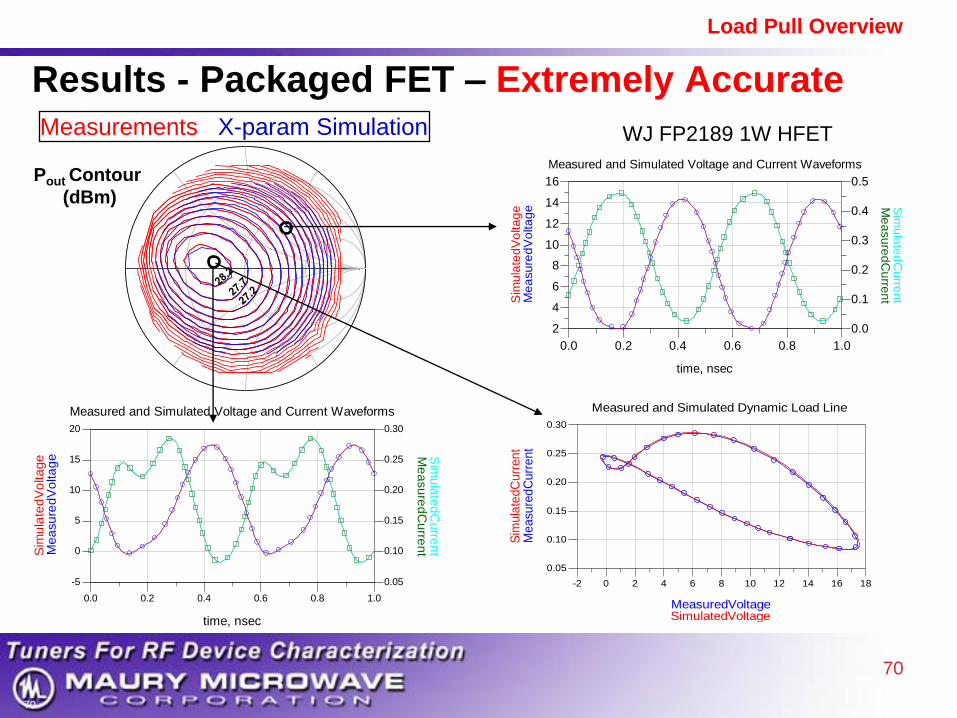
Results - Packaged FET – Extremely Accurate
August 21, 2009
Agilent Restricted
70
0.2 0.4 0.6 0.80.0 1.0
0
5
10
15
-5
20
0.10
0.15
0.20
0.25
0.05
0.30
time, nsec
Me
asu
red
Cu
rren
tMe
asu
red
Vo
lta
ge
Sim
ula
ted
Vo
lta
ge S
imu
late
dC
urre
nt
Measured and Simulated Voltage and Current Waveforms
0.2 0.4 0.6 0.80.0 1.0
4
6
8
10
12
14
2
16
0.1
0.2
0.3
0.4
0.0
0.5
time, nsec
Me
asu
red
Cu
rren
tMe
asu
red
Vo
lta
ge
Sim
ula
ted
Vo
lta
ge S
imu
late
dC
urre
nt
Measured and Simulated Voltage and Current Waveforms
0 2 4 6 8 10 12 14 16-2 18
0.10
0.15
0.20
0.25
0.05
0.30
MeasuredVoltage
Me
asu
red
Cu
rre
nt
SimulatedVoltage
Sim
ula
ted
Cu
rre
nt
Measured and Simulated Dynamic Load Line
Measurements X-param Simulation
Pout Contour
(dBm)
WJ FP2189 1W HFET

71
Load Pull Overview
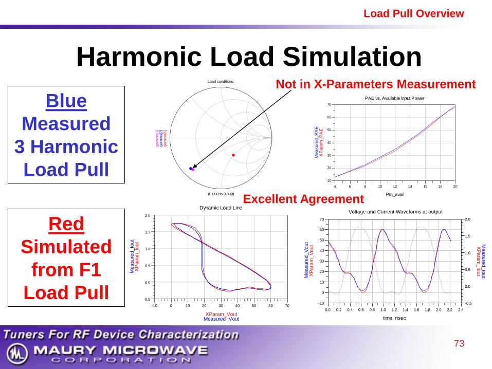
Harmonic Tuning
Simulation with X-Parameters
• Fundamental Load Pull with X-Parameters
• Simulate Harmonic Load Pull in ADS
Benefits:
• Reduce Setup Complexity
• Reduce Measurement Time
• Reduce Data Storage

72
Load Pull Overview
Experiment to Test
Simulation with X-Parameters
DUT
Passive
Tuner
Passive
Tuner
Setup 1 – F1, F2, F3 Load Pull
Passive
Tuner
Passive
Tuner
Cree 10W GaN
DUT
Passive
Tuner
Passive
Tuner
Setup 2 – F1 Load Pull
Cree 10W GaN
With
X-Parameters
73
Load Pull Overview
(0.000 to 0.000)
ga
mm
a[1
]g
am
ma
[2]
ga
mm
a[3
]
Load conditions
6 8 10 12 14 16 184 20
20
30
40
50
60
10
70
Pin_avail
XP
ara
m_
PA
EM
ea
su
red
_P
AE
PAE vs. Available Input Power
Harmonic Load Simulation
0 10 20 30 40 50 60-10 70
0.0
0.5
1.0
1.5
-0.5
2.0
XParam_Vout
XP
ara
m_
Iou
t
Measured_Vout
Me
asu
red
_Io
ut
Dynamic Load Line
0.2 0.4 0.6 0.8 1.0 1.2 1.4 1.6 1.8 2.0 2.20.0 2.4
0.2 0.4 0.6 0.8 1.0 1.2 1.4 1.6 1.8 2.0 2.20.0 2.4
0
10
20
30
40
50
60
-10
70
0.0
0.5
1.0
1.5
-0.5
2.0
time, nsec
XP
ara
m_
Vo
ut X
Pa
ram
_Io
ut
time, nsec
Me
asu
red
_V
ou
t Me
asu
red
_Io
ut
Voltage and Current Waveforms at output
Red
Simulated
from F1
Load Pull
Blue
Measured
3 Harmonic
Load Pull
Not in X-Parameters Measurement
Excellent Agreement
74
Load Pull Overview
Software Integration ATS Software Version 5
• Installs Inside PNA-X
• Tightly Coupled with PNA-X / NVNA
• Full X-Parameter Support

75
Load Pull Overview
Selecting X-Parameters On/Off
Turn off X-Parameters
for Faster Initial Tuning
Turn on X-Parameters
for Sweep Plan to make
Large Signal Model

76
Load Pull Overview
Sweep Plan Setup
• Sweep Plan
• Up to 7 Variables
• Fully Automated Measurement
• Measure over Full Range of Device Operation

77
Load Pull Overview
Hybrid Active Tuning Setup
Simple User Controls
Passive
F1 Tuner
Active
Harmonic
Tuning
Example Configuration
78
Load Pull Overview
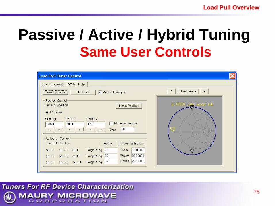
Passive / Active / Hybrid Tuning Same User Controls

79
Load Pull Overview
1. Introduction to Maury Microwave
2. Basics and Benefits of Load Pull
3. Pulsed Measurements
4. Harmonic Load Pull
5. Active Tuning
6. Load Pull with X-Parameters
7. Ultra-Fast Noise Parameters
8. Summary
Outline
80
Load Pull Overview
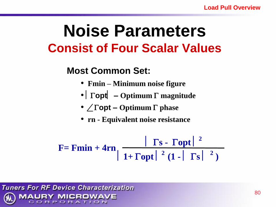
Noise Parameters Consist of Four Scalar Values
Most Common Set:
• Fmin – Minimum noise figure
• opt – Optimum magnitude
• opt – Optimum phase
• rn - Equivalent noise resistance
F= Fmin + 4rn s - opt
2
1+ opt 2
(1 - s 2 )

81
Load Pull Overview
Benefits of Noise Parameters • See noise figure for any source impedance
• Combine with s-parameters for complete Low
Noise Amplifier (LNA) design
– Accurate prediction of LNA performance
• Maury Ultra-Fast Method (200X+ Faster)*
– Faster time to market
– Simpler
– More Accurate than traditional approach
– Test in production = competitive advantage
*Patent Pending

82
Load Pull Overview
Noise Parameter Measurement
Basic Setup

83
Load Pull Overview
Noise Parameter Measurement Sequence
1. System Cal
2. Receiver Cal
3. DUT Measurement

84
Load Pull Overview
Noise Parameter Measurement
Traditional Method 1. System Cal
• Characterize Tuners Over Entire Chart
• One Frequency at a Time
2. Receiver Cal and Measurement
• One Frequency at a Time
• Allows Ideal Impedance Pattern

85
Load Pull Overview
Noise Parameter Measurement
Traditional Method • Time Consuming
– Can Have Drift Issues
• Use System Cal for Long Time
– To Save Time
– Calibrate Parts Separately
• Based on 1969 Paper
– Used by everyone for Almost 40 years

86
Load Pull Overview
Noise Parameter Measurement
New Method*
Main Idea:
• Characterize One Set Of Tuner States
• Sweep Frequency at Each State
• Take Advantage of Fast Sweep of
Modern Instruments
*Patent Pending

87
Load Pull Overview
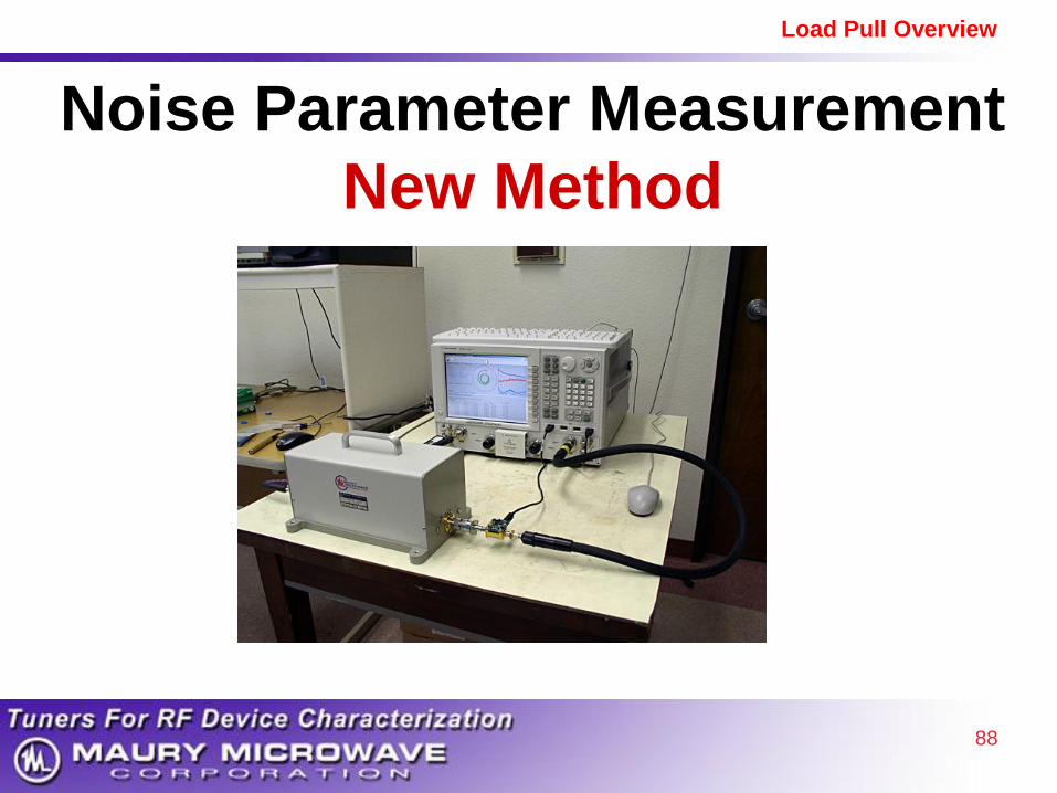
Noise Parameter Measurement
New Method
Noise
Source DUT
Maury
Tuner
PNA-X with Noise Option
88
Load Pull Overview
Noise Parameter Measurement
New Method

89
Load Pull Overview
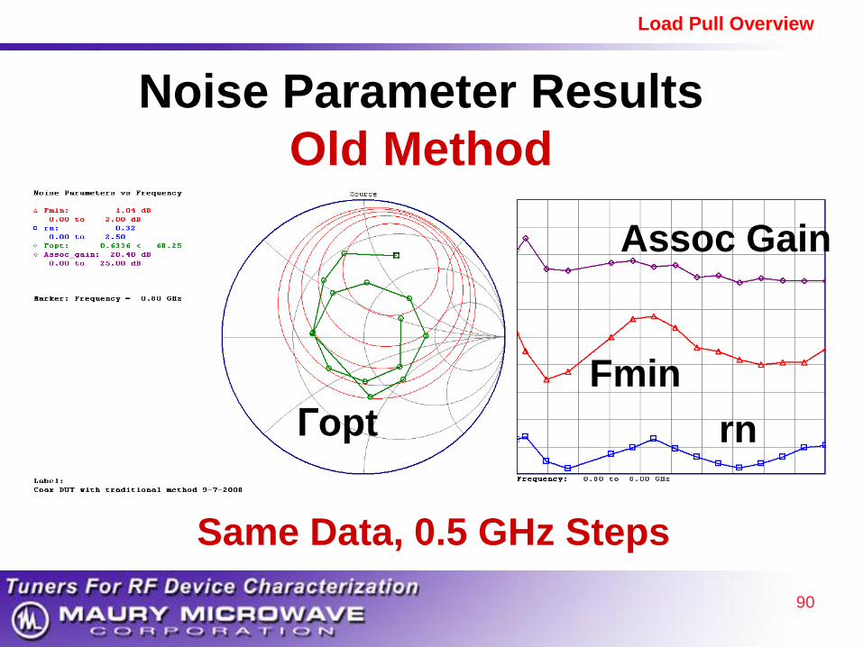
Noise Parameter Results Old Method
73 Frequencies – 30 Hours
90
Load Pull Overview
Same Data, 0.5 GHz Steps
Noise Parameter Results
Old Method
Гopt
Fmin
rn
Assoc Gain

91
Load Pull Overview
Noise Parameter Results New Method*
73 Frequencies – 8 Minutes, 224x Faster
*Patent Pending

92
Load Pull Overview
On-Wafer, 0.8-18 GHz
Fmin= 0.4 dB
Measured Data, No Smoothing Applied

93
Load Pull Overview
DUT Tuner
PNA-X with Noise Option
Noise
Receiver
Module
Noise
Source
Noise Parameter Measurement
50 GHz
94
Load Pull Overview
• Operation 1. Thru Path for S-Parameters
2. Direct Noise Path (Below 26.5 GHz)
3. Down-Convert Path (26.5 to 50 GHz)
• USB Control
Noise Receiver Module
50 GHz
95
Load Pull Overview
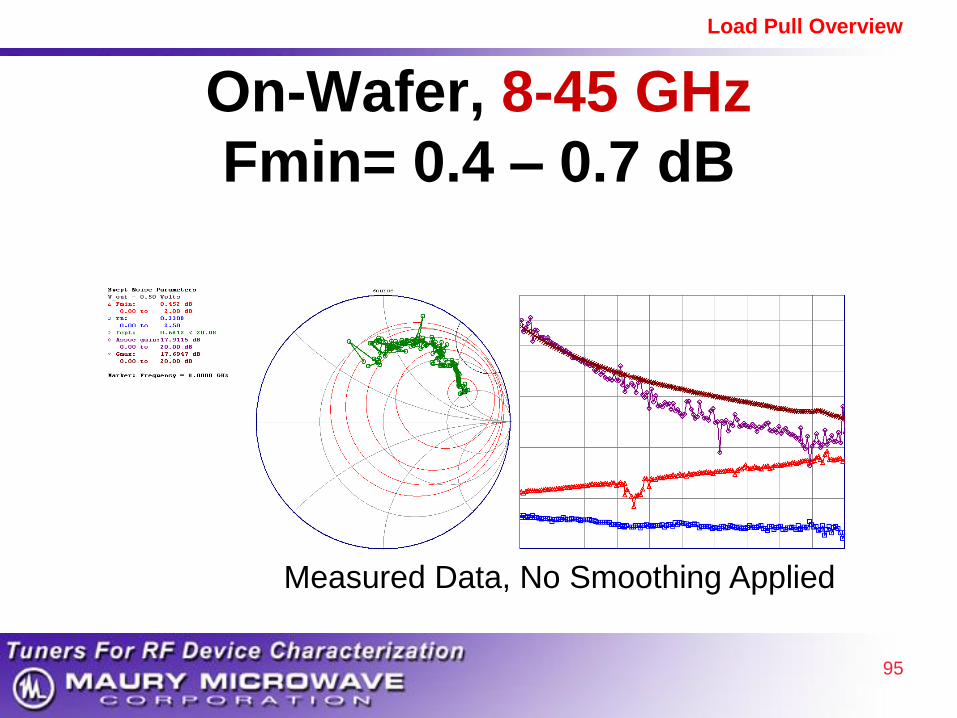
On-Wafer, 8-45 GHz
Fmin= 0.4 – 0.7 dB
Measured Data, No Smoothing Applied

96
Load Pull Overview
Maury Ultra-Fast Noise Parameters
• Industry Breakthrough (224x Faster)
• Simpler Setup and Measurement
• Better Accuracy
• Works Well to Very Low Noise

97
Load Pull Overview
Summary
• Load Pull Applications – Nonlinear Devices
– Stability / Ruggedness
– Harmonic Tuning
– Active Tuning
– Pulsed IV
• Load Pull with X-Parameters – New Paradigm for Modeling and Design
– Instant Large Signal Model
– Major Industry Breakthrough
• Ultra-Fast Noise Parameters – 200 Times Faster
– Much Simpler
– More Accurate
– Major Industry Breakthrough


