1
Loop-O9500R-PTN IMAP-PTN
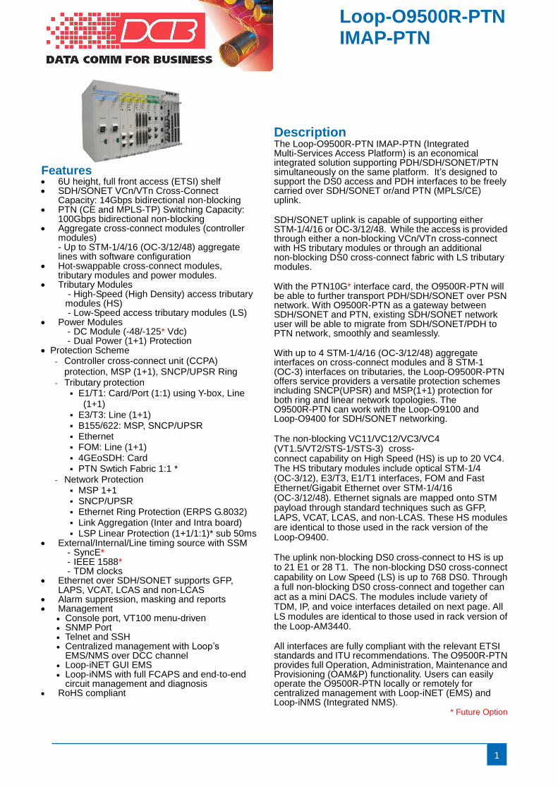
Description The Loop-O9500R-PTN IMAP-PTN (Integrated Multi-Services Access Platform) is an economical integrated solution supporting PDH/SDH/SONET/PTN simultaneously on the same platform. It’s designed to support the DS0 access and PDH interfaces to be freely carried over SDH/SONET or/and PTN (MPLS/CE) uplink. SDH/SONET uplink is capable of supporting either STM-1/4/16 or OC-3/12/48. While the access is provided through either a non-blocking VCn/VTn cross-connect with HS tributary modules or through an additional non-blocking DS0 cross-connect fabric with LS tributary modules. With the PTN10G* interface card, the O9500R-PTN will be able to further transport PDH/SDH/SONET over PSN network. With O9500R-PTN as a gateway between SDH/SONET and PTN, existing SDH/SONET network user will be able to migrate from SDH/SONET/PDH to PTN network, smoothly and seamlessly. With up to 4 STM-1/4/16 (OC-3/12/48) aggregate interfaces on cross-connect modules and 8 STM-1 (OC-3) interfaces on tributaries, the Loop-O9500R-PTN offers service providers a versatile protection schemes including SNCP(UPSR) and MSP(1+1) protection for both ring and linear network topologies. The O9500R-PTN can work with the Loop-O9100 and Loop-O9400 for SDH/SONET networking. The non-blocking VC11/VC12/VC3/VC4 (VT1.5/VT2/STS-1/STS-3) cross- connect capability on High Speed (HS) is up to 20 VC4. The HS tributary modules include optical STM-1/4 (OC-3/12), E3/T3, E1/T1 interfaces, FOM and Fast Ethernet/Gigabit Ethernet over STM-1/4/16 (OC-3/12/48). Ethernet signals are mapped onto STM payload through standard techniques such as GFP, LAPS, VCAT, LCAS, and non-LCAS. These HS modules are identical to those used in the rack version of the Loop-O9400. The uplink non-blocking DS0 cross-connect to HS is up to 21 E1 or 28 T1. The non-blocking DS0 cross-connect capability on Low Speed (LS) is up to 768 DS0. Through a full non-blocking DS0 cross-connect and together can act as a mini DACS. The modules include variety of TDM, IP, and voice interfaces detailed on next page. All LS modules are identical to those used in rack version of the Loop-AM3440. All interfaces are fully compliant with the relevant ETSI standards and ITU recommendations. The O9500R-PTN provides full Operation, Administration, Maintenance and Provisioning (OAM&P) functionality. Users can easily operate the O9500R-PTN locally or remotely for centralized management with Loop-iNET (EMS) and Loop-iNMS (Integrated NMS).
* Future Option
Features • 6U height, full front access (ETSI) shelf • SDH/SONET VCn/VTn Cross-Connect
Capacity: 14Gbps bidirectional non-blocking • PTN (CE and MPLS-TP) Switching Capacity:
100Gbps bidirectional non-blocking • Aggregate cross-connect modules (controller
modules) - Up to STM-1/4/16 (OC-3/12/48) aggregate lines with software configuration
• Hot-swappable cross-connect modules, tributary modules and power modules.
• Tributary Modules - High-Speed (High Density) access tributary modules (HS) - Low-Speed access tributary modules (LS)
• Power Modules - DC Module (-48/-125* Vdc) - Dual Power (1+1) Protection
• Protection Scheme - Controller cross-connect unit (CCPA)
protection, MSP (1+1), SNCP/UPSR Ring - Tributary protection
▪ E1/T1: Card/Port (1:1) using Y-box, Line (1+1)
▪ E3/T3: Line (1+1) ▪ B155/622: MSP, SNCP/UPSR ▪ Ethernet ▪ FOM: Line (1+1) ▪ 4GEoSDH: Card ▪ PTN Swtich Fabric 1:1 *
- Network Protection ▪ MSP 1+1 ▪ SNCP/UPSR ▪ Ethernet Ring Protection (ERPS G.8032) ▪ Link Aggregation (Inter and Intra board) ▪ LSP Linear Protection (1+1/1:1)* sub 50ms
• External/Internal/Line timing source with SSM - SyncE* - IEEE 1588* - TDM clocks
• Ethernet over SDH/SONET supports GFP, LAPS, VCAT, LCAS and non-LCAS
• Alarm suppression, masking and reports • Management
• Console port, VT100 menu-driven • SNMP Port • Telnet and SSH • Centralized management with Loop’s
EMS/NMS over DCC channel • Loop-iNET GUI EMS • Loop-iNMS with full FCAPS and end-to-end
circuit management and diagnosis • RoHS compliant
Loop-O9500R-PTN IMAP-PTN IMAP-PTN
2
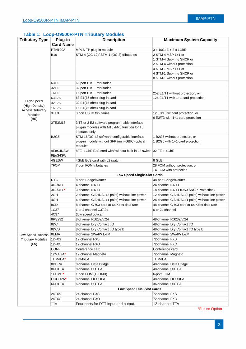
Table 1: Loop-O9500R-PTN Tributary Modules Tributary Type Plug-in
Card Name Description Maximum System Capacity
High-Speed
(High Density)
Access Tributary
Modules
(HS)
PTN10G* MPLS-TP plug-in module 3 x 10GbE + 8 x 1GbE
B16 STM-4 (OC-12)/ STM-1 (OC-3) tributaries 2 STM-4 MSP 1+1 or
1 STM-4 Sub-ring SNCP or
2 STM-4 without protection
4 STM-1 MSP 1+1 or
4 STM-1 Sub-ring SNCP or
8 STM-1 without protection
63TE 63 port E1/T1 tributaries
252 E1/T1 without protection, or
126 E1/T1 with 1+1 card protection
32TE 32 port E1/T1 tributaries
16TE 16 port E1/T1 tributaries
63E75 63 E1(75 ohm) plug-in card
32E75 32 E1(75 ohm) plug-in card
16E75 16 E1(75 ohm) plug-in card
3TE3 3 port E3/T3 tributaries 12 E3/T3 without protection, or
6 E3/T3 with 1+1 card protection
3TE3M13 3 T3 or 3 E3 software programmable interface
plug-in modules with M13 /Mx3 function for T3
interface only
B2G5 STM-16/OC-48 software configurable interface
plug-in module without SFP (mini-GBIC) optical
modules
1 B2G5 without protection, or
1 B2G5 with 1+1 card protection
9EoS4NSW
9EoS4SW
8FE+1GbE EoS card with/ without built-in L2 switch 32 FE + 4GbE
4GESW 4GbE EoS card with L2 switch 8 GbE
7FOM 7 port FOM tributaries 28 FOM without protection, or
14 FOM with protection
Low-Speed Access
Tributary Modules
(LS)
Low Speed Single-Slot Cards
RTB 8-port Bridge/Router 48-port Bridge/Router
4E1/4T1 4-channel E1/T1 24-channel E1/T1
3E1/3T1* 3-channel E1/T1 18-channel E1/T1 (DS0 SNCP Protection)
2GH 2-channel G.SHDSL (2 pairs) without line power 12-channel G.SHDSL (2 pairs) without line power
4GH 4-channel G.SHDSL (1 pairs) without line power 24-channel G.SHDSL (1 pairs) without line power
8CD 8-channel G.703 card at 64 Kbps data rate 48-channel G.703 card at 64 Kbps data rate
1C37
4C37
1 or 4 channel C37.94
(low speed optical)
6 or 24 channel
8RS232 8-channel RS232/V.24 48-channel RS232/V.24
8DC 8-channel Dry Contact I/O 48-channel Dry Contact I/O
8DCB 8-channel Dry Contact I/O type B 48-channel Dry Contact I/O type B
8EMA 8-channel 2W/4W E&M 48-channel 2W/4W E&M
12FXS 12-channel FXS 72-channel FXS
12FXO 12-channel FXO 72-channel FXO
CONF Conference card Conference card
12MAGA* 12-channel Magneto 72-channel Magneto
TDMoEA* TDMoEA TDMoEA
8DBRA 8-channel Data Bridge 48-channel Data Bridge
8UDTEA 8-channel UDTEA 48-channel UDTEA
1FOMB* 1 port FOM (1FOMB) 6-port FOM
OCUDPA* 8-channel OCUDPA 48-channel OCUDPA
6UDTEA 6-channel UDTEA 36-channel UDTEA
Low Speed Dual-Slot Cards
24FXS 24-channel FXS 72-channel FXS
24FXO 24-channel FXO 72-channel FXO
TTA Four ports for DTT input and output. 12-channel TTA
*Future Option
Loop-O9500R-PTN IMAP-PTN IMAP-PTN
3
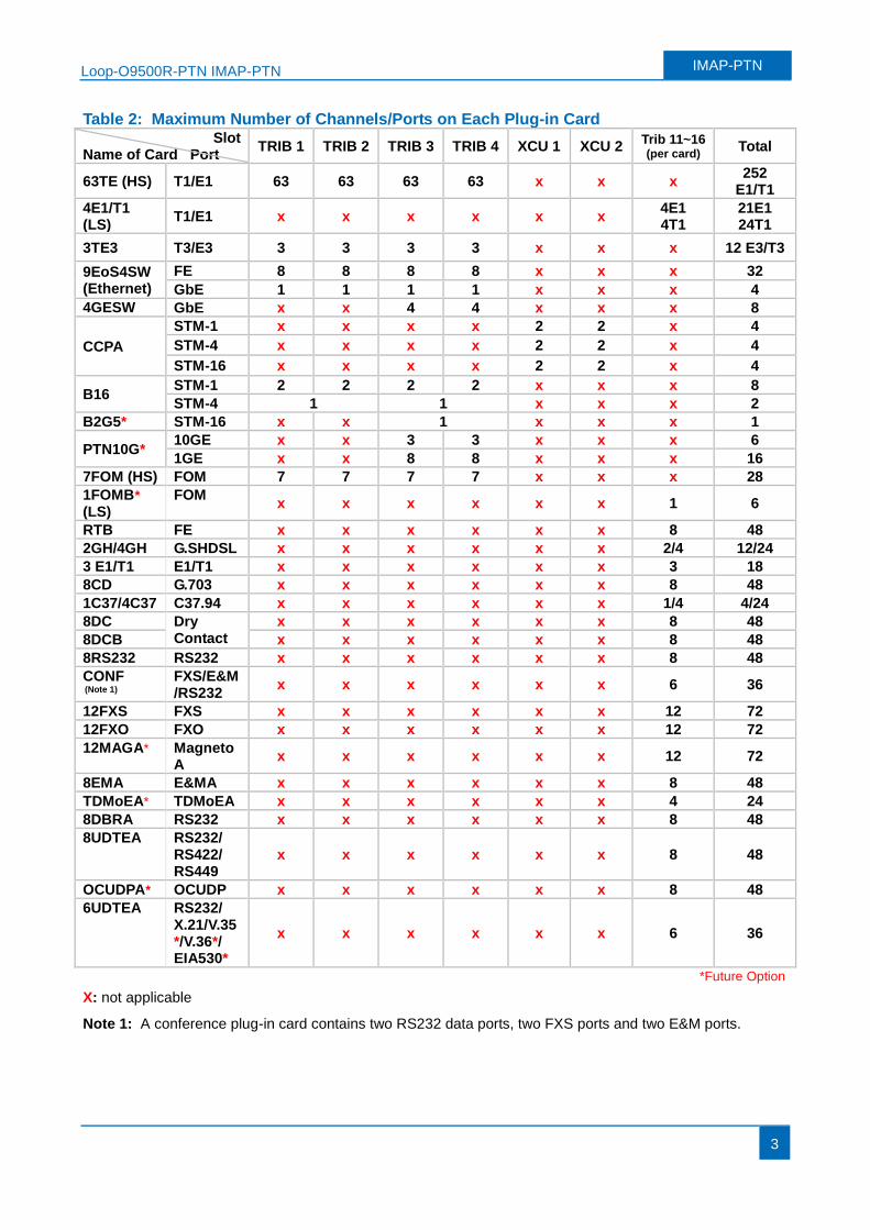
Table 2: Maximum Number of Channels/Ports on Each Plug-in Card Slot
Name of Card Port TRIB 1 TRIB 2 TRIB 3 TRIB 4 XCU 1 XCU 2
Trib 11~16 (per card) Total
63TE (HS) T1/E1 63 63 63 63 x x x 252
E1/T1
4E1/T1 (LS)
T1/E1 x x x x x x 4E1 4T1
21E1 24T1
3TE3 T3/E3 3 3 3 3 x x x 12 E3/T3
9EoS4SW (Ethernet)
FE 8 8 8 8 x x x 32
GbE 1 1 1 1 x x x 4
4GESW GbE x x 4 4 x x x 8
CCPA
STM-1 x x x x 2 2 x 4
STM-4 x x x x 2 2 x 4
STM-16 x x x x 2 2 x 4
B16 STM-1 2 2 2 2 x x x 8
STM-4 1 1 x x x 2
B2G5* STM-16 x x 1 x x x 1
PTN10G* 10GE x x 3 3 x x x 6
1GE x x 8 8 x x x 16
7FOM (HS) FOM 7 7 7 7 x x x 28
1FOMB* (LS)
FOM x x x x x x 1 6
RTB FE x x x x x x 8 48
2GH/4GH G.SHDSL x x x x x x 2/4 12/24
3 E1/T1 E1/T1 x x x x x x 3 18
8CD G.703 x x x x x x 8 48
1C37/4C37 C37.94 x x x x x x 1/4 4/24
8DC Dry Contact
x x x x x x 8 48
8DCB x x x x x x 8 48
8RS232 RS232 x x x x x x 8 48
CONF
(Note 1) FXS/E&M/RS232
x x x x x x 6 36
12FXS FXS x x x x x x 12 72
12FXO FXO x x x x x x 12 72
12MAGA* MagnetoA
x x x x x x 12 72
8EMA E&MA x x x x x x 8 48
TDMoEA* TDMoEA x x x x x x 4 24
8DBRA RS232 x x x x x x 8 48
8UDTEA RS232/ RS422/ RS449
x x x x x x 8 48
OCUDPA* OCUDP x x x x x x 8 48
6UDTEA RS232/ X.21/V.35*/V.36*/ EIA530*
x x x x x x 6 36
*Future Option
X: not applicable
Note 1: A conference plug-in card contains two RS232 data ports, two FXS ports and two E&M ports.
Loop-O9500R-PTN IMAP-PTN IMAP-PTN
4
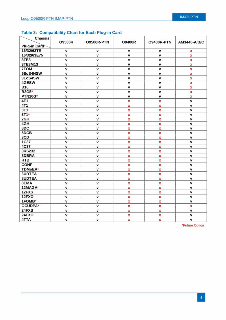
Table 3: Compatibility Chart for Each Plug-in Card
Chassis
Plug-in Card O9500R O9500R-PTN O9400R O9400R-PTN AM3440-A/B/C
16/32/63TE v v v v x
16/32/63E75 v v v v x
3TE3 v v v v x
3TE3M13 v v v v x
7FOM v v v v x
9EoS4NSW v v v v x
9EoS4SW v v v v x
4GESW v v v v x
B16 v v v v x
B2G5* v v v v x
PTN10G* v v v v x
4E1 v v x x v
4T1 v v x x v
3E1 v v x x v
3T1* v v x x v
2GH v v x x v
4GH v v x x v
8DC v v x x v
8DCB v v x x v
8CD v v x x v
1C37 v v x x v
4C37 v v x x v
8RS232 v v x x v
8DBRA v v x x v
RTB v v x x v
CONF v v x x v
TDMoEA* v v x x v
6UDTEA v v x x v
8UDTEA v v x x v
8EMA v v x x v
12MAGA* v v x x v
12FXS v v x x v
12FXO v v x x v
1FOMB* v v x x v
OCUDPA* v v x x x
24FXS v v x x v
24FXO v v x x v
4TTA v v x x v
*Future Option
Loop-O9500R-PTN IMAP-PTN IMAP-PTN
5
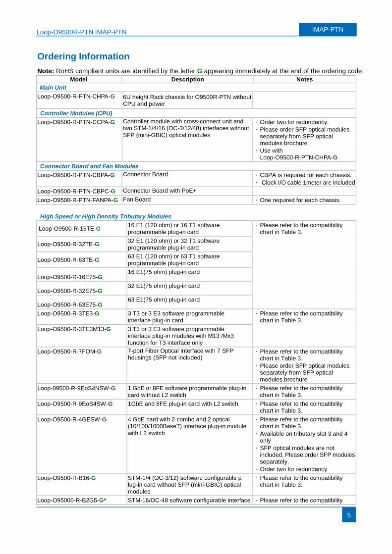
Ordering Information
Note: RoHS compliant units are identified by the letter G appearing immediately at the end of the ordering code.
Model Description Notes
Main Unit
Loop-O9500-R-PTN-CHPA-G 6U height Rack chassis for O9500R-PTN without CPU and power
Controller Modules (CPU)
Loop-O9500-R-PTN-CCPA-G Controller module with cross-connect unit and two STM-1/4/16 (OC-3/12/48) interfaces without SFP (mini-GBIC) optical modules
· Order two for redundancy.
· Please order SFP optical modules separately from SFP optical modules brochure
· Use with Loop-O9500-R-PTN-CHPA-G
Connector Board and Fan Modules
Loop-O9500-R-PTN-CBPA-G Connector Board · CBPA is required for each chassis.
· Clock I/O cable 1meter are included
Loop-O9500-R-PTN-CBPC-G Connector Board with PoE+
Loop-O9500-R-PTN-FANPA-G Fan Board · One required for each chassis.
High Speed or High Density Tributary Modules
Loop-O9500-R-16TE-G 16 E1 (120 ohm) or 16 T1 software programmable plug-in card
· Please refer to the compatibility chart in Table 3.
Loop-O9500-R-32TE-G 32 E1 (120 ohm) or 32 T1 software programmable plug-in card
Loop-O9500-R-63TE-G 63 E1 (120 ohm) or 63 T1 software programmable plug-in card
Loop-O9500-R-16E75-G 16 E1(75 ohm) plug-in card
Loop-O9500-R-32E75-G 32 E1(75 ohm) plug-in card
Loop-O9500-R-63E75-G 63 E1(75 ohm) plug-in card
Loop-O9500-R-3TE3-G 3 T3 or 3 E3 software programmable interface plug-in card
· Please refer to the compatibility chart in Table 3.
Loop-O9500-R-3TE3M13-G 3 T3 or 3 E3 software programmable interface plug-in modules with M13 /Mx3 function for T3 interface only
Loop-O9500-R-7FOM-G 7-port Fiber Optical Interface with 7 SFP housings (SFP not included)
· Please refer to the compatibility chart in Table 3.
· Please order SFP optical modules separately from SFP optical modules brochure
Loop-09500-R-9EoS4NSW-G 1 GbE or 8FE software programmable plug-in card without L2 switch
· Please refer to the compatibility chart in Table 3.
Loop-O9500-R-9EoS4SW-G 1GbE and 8FE plug-in card with L2 switch · Please refer to the compatibility chart in Table 3.
Loop-O9500-R-4GESW-G 4 GbE card with 2 combo and 2 optical (10/100/1000BaseT) interface plug-in module
with L2 switch
· Please refer to the compatibility chart in Table 3.
· Available on tributary slot 3 and 4 only
· SFP optical modules are not included. Please order SFP modules separately.
· Order two for redundancy
Loop-O9500-R-B16-G STM-1/4 (OC-3/12) software configurable p lug-in card without SFP (mini-GBIC) optical modules
· Please refer to the compatibility chart in Table 3.
Loop-O95000-R-B2G5-G* STM-16/OC-48 software configurable interface · Please refer to the compatibility
Loop-O9500R-PTN IMAP-PTN IMAP-PTN
6
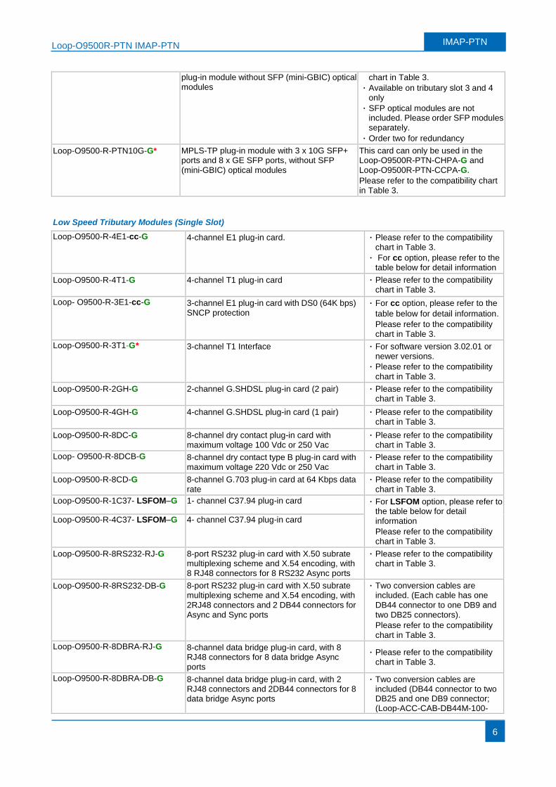
plug-in module without SFP (mini-GBIC) optical modules
chart in Table 3.
· Available on tributary slot 3 and 4 only
· SFP optical modules are not included. Please order SFP modules separately.
· Order two for redundancy
Loop-O9500-R-PTN10G-G* MPLS-TP plug-in module with 3 x 10G SFP+ ports and 8 x GE SFP ports, without SFP (mini-GBIC) optical modules
This card can only be used in the Loop-O9500R-PTN-CHPA-G and Loop-O9500R-PTN-CCPA-G.
Please refer to the compatibility chart in Table 3.
Low Speed Tributary Modules (Single Slot)
Loop-O9500-R-4E1-cc-G 4-channel E1 plug-in card. · Please refer to the compatibility chart in Table 3.
· For cc option, please refer to the table below for detail information
Loop-O9500-R-4T1-G 4-channel T1 plug-in card
· Please refer to the compatibility chart in Table 3.
Loop- O9500-R-3E1-cc-G 3-channel E1 plug-in card with DS0 (64K bps) SNCP protection
· For cc option, please refer to the
table below for detail information.
Please refer to the compatibility chart in Table 3.
Loop-O9500-R-3T1-G* 3-channel T1 Interface · For software version 3.02.01 or newer versions.
· Please refer to the compatibility
chart in Table 3.
Loop-O9500-R-2GH-G 2-channel G.SHDSL plug-in card (2 pair)
· Please refer to the compatibility chart in Table 3.
Loop-O9500-R-4GH-G 4-channel G.SHDSL plug-in card (1 pair)
· Please refer to the compatibility chart in Table 3.
Loop-O9500-R-8DC-G 8-channel dry contact plug-in card with maximum voltage 100 Vdc or 250 Vac
· Please refer to the compatibility chart in Table 3.
Loop- O9500-R-8DCB-G 8-channel dry contact type B plug-in card with maximum voltage 220 Vdc or 250 Vac
· Please refer to the compatibility chart in Table 3.
Loop-O9500-R-8CD-G 8-channel G.703 plug-in card at 64 Kbps data rate
· Please refer to the compatibility chart in Table 3.
Loop-O9500-R-1C37- LSFOM–G 1- channel C37.94 plug-in card · For LSFOM option, please refer to the table below for detail information
Please refer to the compatibility chart in Table 3.
Loop-O9500-R-4C37- LSFOM–G 4- channel C37.94 plug-in card
Loop-O9500-R-8RS232-RJ-G 8-port RS232 plug-in card with X.50 subrate multiplexing scheme and X.54 encoding, with 8 RJ48 connectors for 8 RS232 Async ports
· Please refer to the compatibility chart in Table 3.
Loop-O9500-R-8RS232-DB-G 8-port RS232 plug-in card with X.50 subrate multiplexing scheme and X.54 encoding, with 2RJ48 connectors and 2 DB44 connectors for Async and Sync ports
· Two conversion cables are included. (Each cable has one DB44 connector to one DB9 and two DB25 connectors).
Please refer to the compatibility
chart in Table 3.
Loop-O9500-R-8DBRA-RJ-G 8-channel data bridge plug-in card, with 8 RJ48 connectors for 8 data bridge Async ports
· Please refer to the compatibility chart in Table 3.
Loop-O9500-R-8DBRA-DB-G 8-channel data bridge plug-in card, with 2 RJ48 connectors and 2DB44 connectors for 8 data bridge Async ports
· Two conversion cables are included (DB44 connector to two DB25 and one DB9 connector; (Loop-ACC-CAB-DB44M-100-
Loop-O9500R-PTN IMAP-PTN IMAP-PTN
7
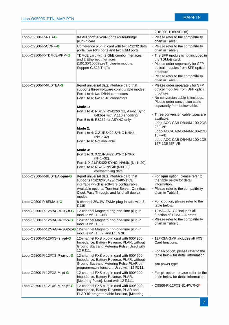
2DB25F-1DB09F-DB).
Loop-O9500-R-RTB-G 8-LAN port/64 WAN ports router/bridge plug-in card
· Please refer to the compatibility chart in Table 3..
Loop-O9500-R-CONF-G Conference plug-in card with two RS232 data ports, two FXS ports and two E&M ports
· Please refer to the compatibility chart in Table 3.
Loop-O9500-R-TDMoE-PPM-G TDMoE card with 2 GbE combo interfaces and 2 Ethernet interfaces (10/100/1000BaseT) plug-in module.
Support G.823 Traffic
· The SFP module is not included in the TDMoE card.
· Please order separately for SFP optical modules from SFP optical
brochure.
· Please refer to the compatibility
chart in Table 3.
Loop-O9500-R-6UDTEA-G 6-port universal data interface card that supports three software configurable modes:
Port 1 to 4: two DB44 connectors
Port 5 to 6: two RJ48 connectors
Mode 1:
Port 1 to 4: RS232/RS422/X.21, Async/Sync 64kbps with V.110 encoding
Port 5 to 6: RS232 for ASYNC only
Mode 2:
Port 1 to 4: X.21/RS422 SYNC N*64k,
(N=1~32)
Port 5 to 6: Not available
Mode 3:
Port 1 to 3: X.21/RS422 SYNC N*64k, (N=1~32).
Port 4: X.21/RS422 SYNC, N*64k, (N=1~20).
Port 5 to 6: RS232 N*64k (N=1~6)
oversampling data.
· Please order separately for SFP optical modules from SFP optical brochure.
· No conversion cable is included. Please order conversion cable separately from below table.
· Three conversion cable types are
available:
Loop-ACC-CAB-DB44M-100-2DB
25F-VB
Loop-ACC-CAB-DB44M-100-2DB15F-VB
Loop-ACC-CAB-DB44M-100-1DB15F-1DB25F-VB
Loop-O9500-R-8UDTEA-opm-G 8-port universal data interface card that supports RS232/RS422/RS485 DCE interface which is software configurable
Available options: Terminal Server, Omnibus, Clock Pass Through, and full-/half duplex modes
· For opm option, please refer to the table below for detail information.
· Please refer to the compatibility chart in Table 3.
Loop-O9500-R-8EMA-x-G 8-channel 2W/4W E&MA plug-in card with 8 RJ45
· For x option, please refer to the table below.
Loop-O9500-R-12MAG-A-1G-x-G 12-channel Magneto ring-one-time plug-in module w/ L1. GND
· 12MAG-A-1G2 includes all function of 12MAG-A cards.
· Please refer to the compatibility chart in Table 3.
Loop-O9500-R-12MAG-A-12-x-G 12-channel Magneto ring-one-time plug-in module w/ L1, L2
Loop-O9500-R-12MAG-A-1G2-x-G 12-channel Magneto ring-one-time plug-in module w/ L1, L2, and L1. GND
Loop-O9500-R-12FXS- sn-pt-G 12-channel FXS plug-in card with 600/ 900 Impedance, Battery Reverse, PLAR, without Ground Start and Metering Pulse. Used with 12 RJ11.
· 12FXSA-GMP includes all FXS Card functions.
· For sn option, please refer to the table below for detail information.
· pt= power type
· For pt option, please refer to the table below for detail information
· O9500-R-12FXS-S1-PWR-G*
Loop-O9500-R-12FXS-P-sn-pt-G 12-channel FXS plug-in card with 600/ 900 Impedance, Battery Reverse, PLAR, without Ground Start and Metering Pulse PLAR bit programmable function. Used with 12 RJ11.
Loop-O9500-R-12FXS-M-pt-G 12-channel FXS plug-in card with 600/ 900 Impedance, Battery Reverse, PLAR, [Metering Pulse]. Used with 12 RJ11.
Loop-O9500-R-12FXS-MPP-pt-G 12-channel FXS plug-in card with 600/ 900 Impedance, Battery Reverse, PLAR and PLAR bit programmable function, [Metering
Loop-O9500R-PTN IMAP-PTN IMAP-PTN
8
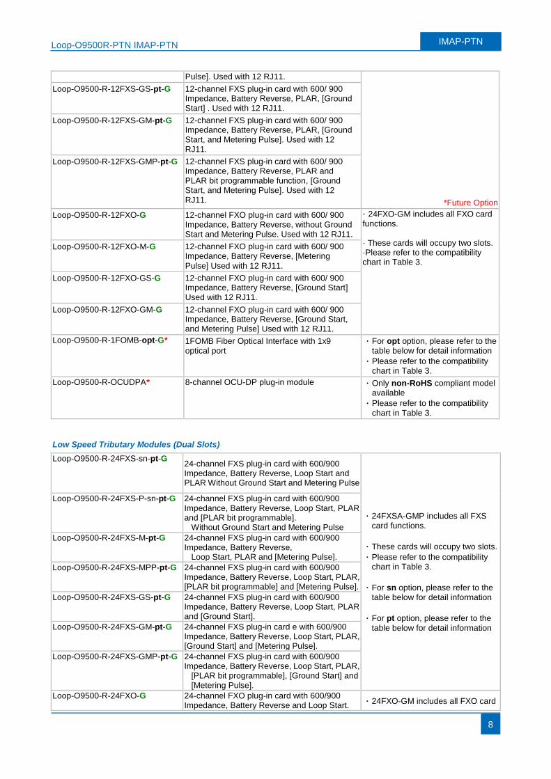
Pulse]. Used with 12 RJ11.
*Future Option
Loop-O9500-R-12FXS-GS-pt-G 12-channel FXS plug-in card with 600/ 900 Impedance, Battery Reverse, PLAR, [Ground Start] . Used with 12 RJ11.
Loop-O9500-R-12FXS-GM-pt-G 12-channel FXS plug-in card with 600/ 900 Impedance, Battery Reverse, PLAR, [Ground Start, and Metering Pulse]. Used with 12 RJ11.
Loop-O9500-R-12FXS-GMP-pt-G 12-channel FXS plug-in card with 600/ 900 Impedance, Battery Reverse, PLAR and PLAR bit programmable function, [Ground Start, and Metering Pulse]. Used with 12 RJ11.
Loop-O9500-R-12FXO-G 12-channel FXO plug-in card with 600/ 900 Impedance, Battery Reverse, without Ground Start and Metering Pulse. Used with 12 RJ11.
· 24FXO-GM includes all FXO card functions. · These cards will occupy two slots. ·Please refer to the compatibility chart in Table 3.
Loop-O9500-R-12FXO-M-G 12-channel FXO plug-in card with 600/ 900 Impedance, Battery Reverse, [Metering
Pulse] Used with 12 RJ11.
Loop-O9500-R-12FXO-GS-G 12-channel FXO plug-in card with 600/ 900 Impedance, Battery Reverse, [Ground Start] Used with 12 RJ11.
Loop-O9500-R-12FXO-GM-G 12-channel FXO plug-in card with 600/ 900 Impedance, Battery Reverse, [Ground Start, and Metering Pulse] Used with 12 RJ11.
Loop-O9500-R-1FOMB-opt-G* 1FOMB Fiber Optical Interface with 1x9 optical port
· For opt option, please refer to the table below for detail information
· Please refer to the compatibility chart in Table 3.
Loop-O9500-R-OCUDPA* 8-channel OCU-DP plug-in module · Only non-RoHS compliant model available
· Please refer to the compatibility
chart in Table 3.
Low Speed Tributary Modules (Dual Slots)
Loop-O9500-R-24FXS-sn-pt-G 24-channel FXS plug-in card with 600/900 Impedance, Battery Reverse, Loop Start and PLAR Without Ground Start and Metering Pulse
· 24FXSA-GMP includes all FXS card functions.
· These cards will occupy two slots.
· Please refer to the compatibility chart in Table 3.
· For sn option, please refer to the table below for detail information
· For pt option, please refer to the
table below for detail information
Loop-O9500-R-24FXS-P-sn-pt-G 24-channel FXS plug-in card with 600/900 Impedance, Battery Reverse, Loop Start, PLAR and [PLAR bit programmable].
Without Ground Start and Metering Pulse
Loop-O9500-R-24FXS-M-pt-G 24-channel FXS plug-in card with 600/900 Impedance, Battery Reverse,
Loop Start, PLAR and [Metering Pulse].
Loop-O9500-R-24FXS-MPP-pt-G 24-channel FXS plug-in card with 600/900 Impedance, Battery Reverse, Loop Start, PLAR, [PLAR bit programmable] and [Metering Pulse].
Loop-O9500-R-24FXS-GS-pt-G 24-channel FXS plug-in card with 600/900 Impedance, Battery Reverse, Loop Start, PLAR and [Ground Start].
Loop-O9500-R-24FXS-GM-pt-G 24-channel FXS plug-in card e with 600/900 Impedance, Battery Reverse, Loop Start, PLAR, [Ground Start] and [Metering Pulse].
Loop-O9500-R-24FXS-GMP-pt-G 24-channel FXS plug-in card with 600/900 Impedance, Battery Reverse, Loop Start, PLAR,
[PLAR bit programmable], [Ground Start] and [Metering Pulse].
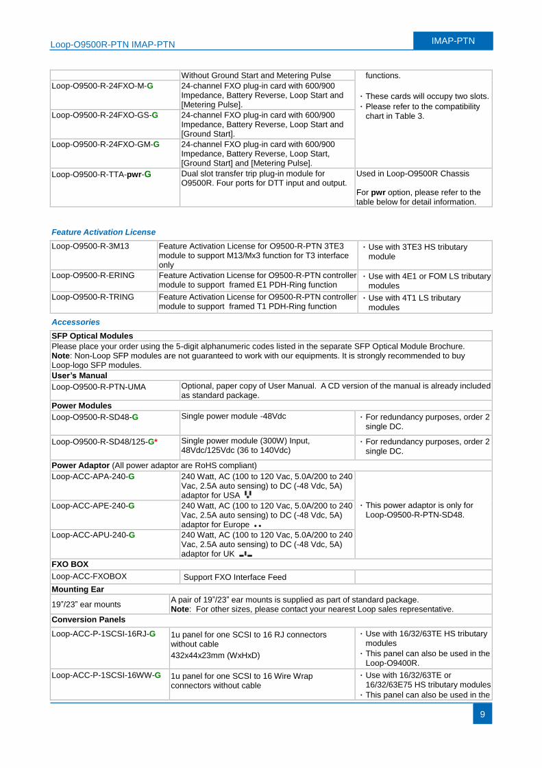
Loop-O9500-R-24FXO-G 24-channel FXO plug-in card with 600/900 Impedance, Battery Reverse and Loop Start.
· 24FXO-GM includes all FXO card
Loop-O9500R-PTN IMAP-PTN IMAP-PTN
9
Without Ground Start and Metering Pulse functions.
· These cards will occupy two slots.
· Please refer to the compatibility chart in Table 3.
Loop-O9500-R-24FXO-M-G 24-channel FXO plug-in card with 600/900 Impedance, Battery Reverse, Loop Start and [Metering Pulse].
Loop-O9500-R-24FXO-GS-G 24-channel FXO plug-in card with 600/900 Impedance, Battery Reverse, Loop Start and [Ground Start].
Loop-O9500-R-24FXO-GM-G 24-channel FXO plug-in card with 600/900 Impedance, Battery Reverse, Loop Start, [Ground Start] and [Metering Pulse].
Loop-O9500-R-TTA-pwr-G Dual slot transfer trip plug-in module for O9500R. Four ports for DTT input and output.
Used in Loop-O9500R Chassis For pwr option, please refer to the table below for detail information.
Feature Activation License
Loop-O9500-R-3M13 Feature Activation License for O9500-R-PTN 3TE3 module to support M13/Mx3 function for T3 interface only
· Use with 3TE3 HS tributary module
Loop-O9500-R-ERING Feature Activation License for O9500-R-PTN controller module to support framed E1 PDH-Ring function
· Use with 4E1 or FOM LS tributary modules
Loop-O9500-R-TRING Feature Activation License for O9500-R-PTN controller module to support framed T1 PDH-Ring function
· Use with 4T1 LS tributary modules
Accessories
SFP Optical Modules
Please place your order using the 5-digit alphanumeric codes listed in the separate SFP Optical Module Brochure. Note: Non-Loop SFP modules are not guaranteed to work with our equipments. It is strongly recommended to buy Loop-logo SFP modules.
User’s Manual
Loop-O9500-R-PTN-UMA Optional, paper copy of User Manual. A CD version of the manual is already included as standard package.
Power Modules
Loop-O9500-R-SD48-G Single power module -48Vdc · For redundancy purposes, order 2 single DC.
Loop-O9500-R-SD48/125-G* Single power module (300W) Input, 48Vdc/125Vdc (36 to 140Vdc)
· For redundancy purposes, order 2 single DC.
Power Adaptor (All power adaptor are RoHS compliant)
Loop-ACC-APA-240-G 240 Watt, AC (100 to 120 Vac, 5.0A/200 to 240 Vac, 2.5A auto sensing) to DC (-48 Vdc, 5A) adaptor for USA
· This power adaptor is only for Loop-O9500-R-PTN-SD48.
Loop-ACC-APE-240-G 240 Watt, AC (100 to 120 Vac, 5.0A/200 to 240 Vac, 2.5A auto sensing) to DC (-48 Vdc, 5A) adaptor for Europe
Loop-ACC-APU-240-G 240 Watt, AC (100 to 120 Vac, 5.0A/200 to 240 Vac, 2.5A auto sensing) to DC (-48 Vdc, 5A) adaptor for UK
FXO BOX
Loop-ACC-FXOBOX Support FXO Interface Feed
Mounting Ear
19”/23” ear mounts A pair of 19”/23” ear mounts is supplied as part of standard package. Note: For other sizes, please contact your nearest Loop sales representative.
Conversion Panels
Loop-ACC-P-1SCSI-16RJ-G 1u panel for one SCSI to 16 RJ connectors without cable
432x44x23mm (WxHxD)
· Use with 16/32/63TE HS tributary modules
· This panel can also be used in the Loop-O9400R.
Loop-ACC-P-1SCSI-16WW-G 1u panel for one SCSI to 16 Wire Wrap connectors without cable
· Use with 16/32/63TE or 16/32/63E75 HS tributary modules
· This panel can also be used in the
Loop-O9500R-PTN IMAP-PTN IMAP-PTN
10
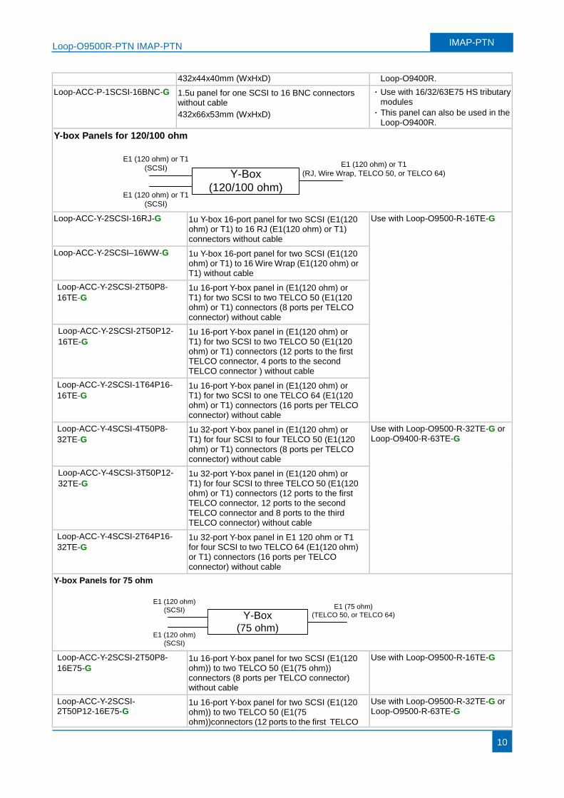
432x44x40mm (WxHxD) Loop-O9400R.
Loop-ACC-P-1SCSI-16BNC-G 1.5u panel for one SCSI to 16 BNC connectors without cable
432x66x53mm (WxHxD)
· Use with 16/32/63E75 HS tributary modules
· This panel can also be used in the Loop-O9400R.
Y-box Panels for 120/100 ohm
Y-Box
(120/100 ohm)
E1 (120 ohm) or T1
(SCSI)
E1 (120 ohm) or T1
(SCSI)
E1 (120 ohm) or T1
(RJ, Wire Wrap, TELCO 50, or TELCO 64)
Loop-ACC-Y-2SCSI-16RJ-G 1u Y-box 16-port panel for two SCSI (E1(120
ohm) or T1) to 16 RJ (E1(120 ohm) or T1) connectors without cable
Use with Loop-O9500-R-16TE-G
Loop-ACC-Y-2SCSI–16WW-G 1u Y-box 16-port panel for two SCSI (E1(120 ohm) or T1) to 16 Wire Wrap (E1(120 ohm) or T1) without cable
Loop-ACC-Y-2SCSI-2T50P8-
16TE-G 1u 16-port Y-box panel in (E1(120 ohm) or T1) for two SCSI to two TELCO 50 (E1(120 ohm) or T1) connectors (8 ports per TELCO connector) without cable
Loop-ACC-Y-2SCSI-2T50P12-
16TE-G 1u 16-port Y-box panel in (E1(120 ohm) or T1) for two SCSI to two TELCO 50 (E1(120 ohm) or T1) connectors (12 ports to the first TELCO connector, 4 ports to the second TELCO connector ) without cable
Loop-ACC-Y-2SCSI-1T64P16-
16TE-G 1u 16-port Y-box panel in (E1(120 ohm) or T1) for two SCSI to one TELCO 64 (E1(120 ohm) or T1) connectors (16 ports per TELCO connector) without cable
Loop-ACC-Y-4SCSI-4T50P8-
32TE-G 1u 32-port Y-box panel in (E1(120 ohm) or T1) for four SCSI to four TELCO 50 (E1(120 ohm) or T1) connectors (8 ports per TELCO connector) without cable
Use with Loop-O9500-R-32TE-G or Loop-O9400-R-63TE-G
Loop-ACC-Y-4SCSI-3T50P12-
32TE-G 1u 32-port Y-box panel in (E1(120 ohm) or T1) for four SCSI to three TELCO 50 (E1(120 ohm) or T1) connectors (12 ports to the first TELCO connector, 12 ports to the second TELCO connector and 8 ports to the third TELCO connector) without cable
Loop-ACC-Y-4SCSI-2T64P16-
32TE-G 1u 32-port Y-box panel in E1 120 ohm or T1 for four SCSI to two TELCO 64 (E1(120 ohm) or T1) connectors (16 ports per TELCO connector) without cable
Y-box Panels for 75 ohm
Y-Box
(75 ohm)
E1 (120 ohm)
(SCSI)
E1 (120 ohm)
(SCSI)
E1 (75 ohm)
(TELCO 50, or TELCO 64)
Loop-ACC-Y-2SCSI-2T50P8-
16E75-G 1u 16-port Y-box panel for two SCSI (E1(120 ohm)) to two TELCO 50 (E1(75 ohm)) connectors (8 ports per TELCO connector) without cable
Use with Loop-O9500-R-16TE-G
Loop-ACC-Y-2SCSI- 2T50P12-16E75-G
1u 16-port Y-box panel for two SCSI (E1(120 ohm)) to two TELCO 50 (E1(75 ohm))connectors (12 ports to the first TELCO
Use with Loop-O9500-R-32TE-G or Loop-O9500-R-63TE-G
Loop-O9500R-PTN IMAP-PTN IMAP-PTN
11
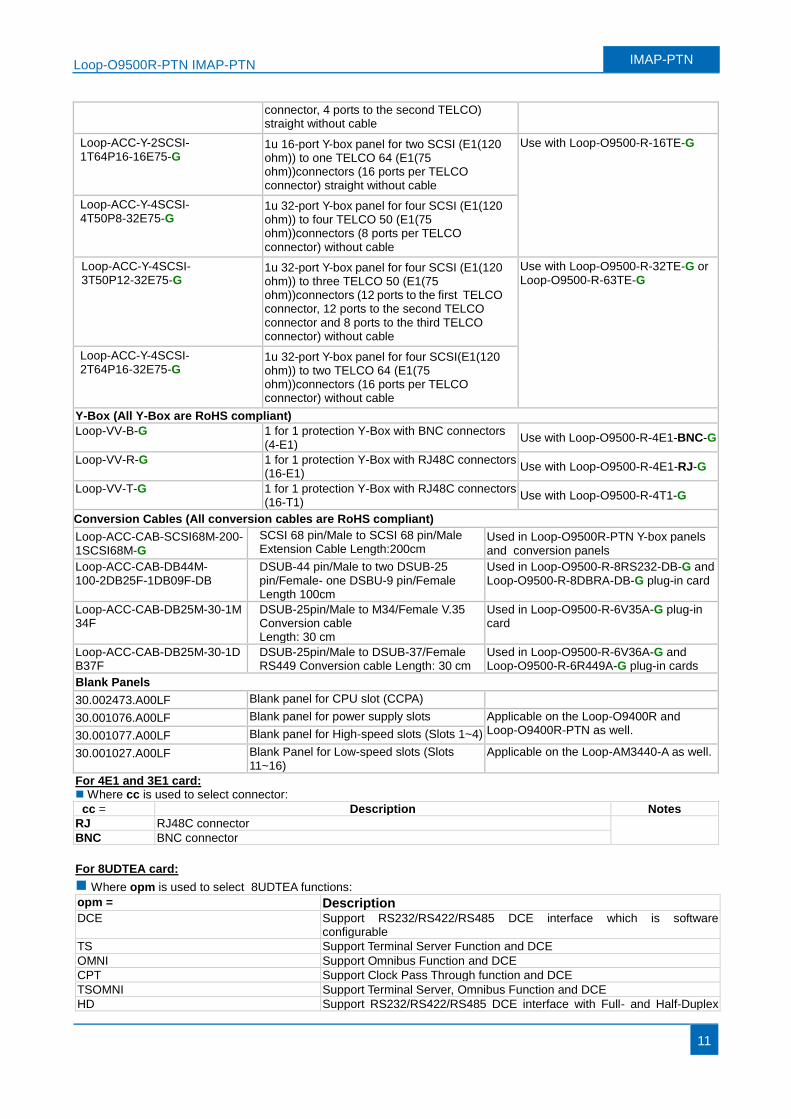
connector, 4 ports to the second TELCO) straight without cable
Loop-ACC-Y-2SCSI- 1T64P16-16E75-G
1u 16-port Y-box panel for two SCSI (E1(120 ohm)) to one TELCO 64 (E1(75 ohm))connectors (16 ports per TELCO connector) straight without cable
Use with Loop-O9500-R-16TE-G
Loop-ACC-Y-4SCSI- 4T50P8-32E75-G
1u 32-port Y-box panel for four SCSI (E1(120 ohm)) to four TELCO 50 (E1(75 ohm))connectors (8 ports per TELCO connector) without cable
Loop-ACC-Y-4SCSI- 3T50P12-32E75-G
1u 32-port Y-box panel for four SCSI (E1(120 ohm)) to three TELCO 50 (E1(75 ohm))connectors (12 ports to the first TELCO connector, 12 ports to the second TELCO connector and 8 ports to the third TELCO connector) without cable
Use with Loop-O9500-R-32TE-G or Loop-O9500-R-63TE-G
Loop-ACC-Y-4SCSI- 2T64P16-32E75-G
1u 32-port Y-box panel for four SCSI(E1(120 ohm)) to two TELCO 64 (E1(75 ohm))connectors (16 ports per TELCO connector) without cable
Y-Box (All Y-Box are RoHS compliant)
Loop-VV-B-G 1 for 1 protection Y-Box with BNC connectors (4-E1)
Use with Loop-O9500-R-4E1-BNC-G
Loop-VV-R-G 1 for 1 protection Y-Box with RJ48C connectors (16-E1)
Use with Loop-O9500-R-4E1-RJ-G
Loop-VV-T-G 1 for 1 protection Y-Box with RJ48C connectors (16-T1)
Use with Loop-O9500-R-4T1-G
Conversion Cables (All conversion cables are RoHS compliant)
Loop-ACC-CAB-SCSI68M-200-1SCSI68M-G
SCSI 68 pin/Male to SCSI 68 pin/Male Extension Cable Length:200cm
Used in Loop-O9500R-PTN Y-box panels and conversion panels
Loop-ACC-CAB-DB44M- 100-2DB25F-1DB09F-DB
DSUB-44 pin/Male to two DSUB-25 pin/Female- one DSBU-9 pin/Female Length 100cm
Used in Loop-O9500-R-8RS232-DB-G and Loop-O9500-R-8DBRA-DB-G plug-in card
Loop-ACC-CAB-DB25M-30-1M34F
DSUB-25pin/Male to M34/Female V.35 Conversion cable Length: 30 cm
Used in Loop-O9500-R-6V35A-G plug-in card
Loop-ACC-CAB-DB25M-30-1DB37F
DSUB-25pin/Male to DSUB-37/Female RS449 Conversion cable Length: 30 cm
Used in Loop-O9500-R-6V36A-G and Loop-O9500-R-6R449A-G plug-in cards
Blank Panels
30.002473.A00LF Blank panel for CPU slot (CCPA)
30.001076.A00LF Blank panel for power supply slots Applicable on the Loop-O9400R and Loop-O9400R-PTN as well. 30.001077.A00LF Blank panel for High-speed slots (Slots 1~4)
30.001027.A00LF Blank Panel for Low-speed slots (Slots 11~16)
Applicable on the Loop-AM3440-A as well.
For 4E1 and 3E1 card: Where cc is used to select connector:
cc = Description Notes
RJ RJ48C connector
BNC BNC connector
For 8UDTEA card:
Where opm is used to select 8UDTEA functions:
opm = Description
DCE Support RS232/RS422/RS485 DCE interface which is software configurable
TS Support Terminal Server Function and DCE
OMNI Support Omnibus Function and DCE
CPT Support Clock Pass Through function and DCE
TSOMNI Support Terminal Server, Omnibus Function and DCE
HD Support RS232/RS422/RS485 DCE interface with Full- and Half-Duplex
Loop-O9500R-PTN IMAP-PTN IMAP-PTN
12
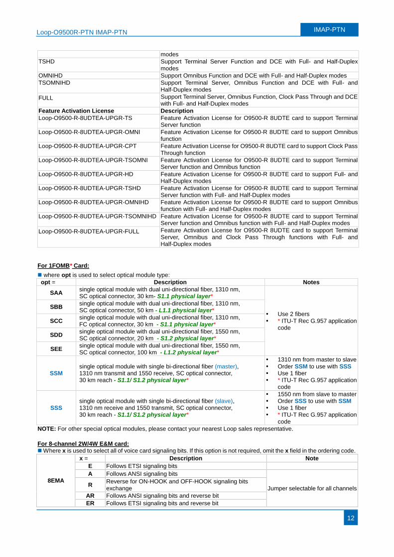
modes
TSHD Support Terminal Server Function and DCE with Full- and Half-Duplex modes
OMNIHD Support Omnibus Function and DCE with Full- and Half-Duplex modes
TSOMNIHD Support Terminal Server, Omnibus Function and DCE with Full- and Half-Duplex modes
FULL Support Terminal Server, Omnibus Function, Clock Pass Through and DCE with Full- and Half-Duplex modes
Feature Activation License Description
Loop-O9500-R-8UDTEA-UPGR-TS Feature Activation License for O9500-R 8UDTE card to support Terminal Server function
Loop-O9500-R-8UDTEA-UPGR-OMNI Feature Activation License for O9500-R 8UDTE card to support Omnibus function
Loop-O9500-R-8UDTEA-UPGR-CPT Feature Activation License for O9500-R 8UDTE card to support Clock Pass Through function
Loop-O9500-R-8UDTEA-UPGR-TSOMNI Feature Activation License for O9500-R 8UDTE card to support Terminal Server function and Omnibus function
Loop-O9500-R-8UDTEA-UPGR-HD Feature Activation License for O9500-R 8UDTE card to support Full- and Half-Duplex modes
Loop-O9500-R-8UDTEA-UPGR-TSHD Feature Activation License for O9500-R 8UDTE card to support Terminal Server function with Full- and Half-Duplex modes
Loop-O9500-R-8UDTEA-UPGR-OMNIHD Feature Activation License for O9500-R 8UDTE card to support Omnibus function with Full- and Half-Duplex modes
Loop-O9500-R-8UDTEA-UPGR-TSOMNIHD Feature Activation License for O9500-R 8UDTE card to support Terminal Server function and Omnibus function with Full- and Half-Duplex modes
Loop-O9500-R-8UDTEA-UPGR-FULL Feature Activation License for O9500-R 8UDTE card to support Terminal Server, Omnibus and Clock Pass Through functions with Full- and Half-Duplex modes
For 1FOMB* Card:
where opt is used to select optical module type:
opt = Description Notes
SAA single optical module with dual uni-directional fiber, 1310 nm, SC optical connector, 30 km- S1.1 physical layer*
Use 2 fibers * ITU-T Rec G.957 application
code
SBB single optical module with dual uni-directional fiber, 1310 nm, SC optical connector, 50 km - L1.1 physical layer*
SCC single optical module with dual uni-directional fiber, 1310 nm, FC optical connector, 30 km - S1.1 physical layer*
SDD single optical module with dual uni-directional fiber, 1550 nm, SC optical connector, 20 km - S1.2 physical layer*
SEE single optical module with dual uni-directional fiber, 1550 nm, SC optical connector, 100 km - L1.2 physical layer*
SSM single optical module with single bi-directional fiber (master), 1310 nm transmit and 1550 receive, SC optical connector, 30 km reach - S1.1/ S1.2 physical layer*
1310 nm from master to slave Order SSM to use with SSS Use 1 fiber * ITU-T Rec G.957 application
code
SSS single optical module with single bi-directional fiber (slave), 1310 nm receive and 1550 transmit, SC optical connector, 30 km reach - S1.1/ S1.2 physical layer*
1550 nm from slave to master Order SSS to use with SSM Use 1 fiber * ITU-T Rec G.957 application
code
NOTE: For other special optical modules, please contact your nearest Loop sales representative.
For 8-channel 2W/4W E&M card: Where x is used to select all of voice card signaling bits. If this option is not required, omit the x field in the ordering code.
8EMA
x = Description Note
E Follows ETSI signaling bits
A Follows ANSI signaling bits
Jumper selectable for all channels R
Reverse for ON-HOOK and OFF-HOOK signaling bits exchange
AR Follows ANSI signaling bits and reverse bit
ER Follows ETSI signaling bits and reverse bit
Loop-O9500R-PTN IMAP-PTN IMAP-PTN
13
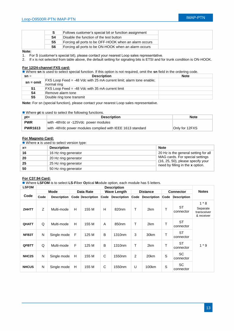
S Follows customer’s special bit or function assignment
S4 Disable the function of the test button
S5 Forcing all ports to be OFF-HOOK when an alarm occurs
S6 Forcing all ports to be ON-HOOK when an alarm occurs
Note: 1. For S (customer‘s special bit), please contact your nearest Loop sales representative. 2. If x is not selected from table above, the default setting for signaling bits is ETSI and for trunk condition is ON-HOOK.
For 12/24-channel FXS card: Where sn is used to select special function. If this option is not required, omit the sn field in the ordering code.
sn = Description Note
sn = omit FXS Loop Feed = -48 Vdc with 25 mA current limit; alarm tone enable; normal ring
S1 FXS Loop Feed = -48 Vdc with 35 mA current limit
S4 Remove alarm tone
S5 Double ring tone transmit
Note: For sn (special function), please contact your nearest Loop sales representative.
Where pt is used to select the following functions.
pt= Description Note
PWR with -48Vdc or -125Vdc power modules
PWR1613 with -48Vdc power modules complied with IEEE 1613 standard Only for 12FXS
For Magneto Card:
Where x is used to select version type:
x= Description Note
16 16 Hz ring generator 20 Hz is the general setting for all MAG cards. For special settings (16, 25, 50), please specify your need by filling in the x option.
20 20 Hz ring generator
25 25 Hz ring generator
50 50 Hz ring generator
For C37.94 Card:
Where LSFOM is to select LS-Fiber Optical Module option, each module has 5 letters.
LSFOM Description Notes
Code Mode Data Rate Wave Length Distance Connector
Code Description Code Description Code Description Code Description Code Description
ZHHTT Z Multi-mode H 155 M H 820nm T 2km T ST
connector
1 * 8
Separate transceiver & receiver
QHATT Q Multi-mode H 155 M A 850nm T 2km T ST
connector
1 * 9
NFB3T N Single mode F 125 M B 1310nm 3 30km T ST
connector
QFBTT Q Multi-mode F 125 M B 1310nm T 2km T ST
connector
NHC2S N Single mode H 155 M C 1550nm 2 20km S SC
connector
NHCUS N Single mode H 155 M C 1550nm U 100km S SC
connector
Loop-O9500R-PTN IMAP-PTN IMAP-PTN
14
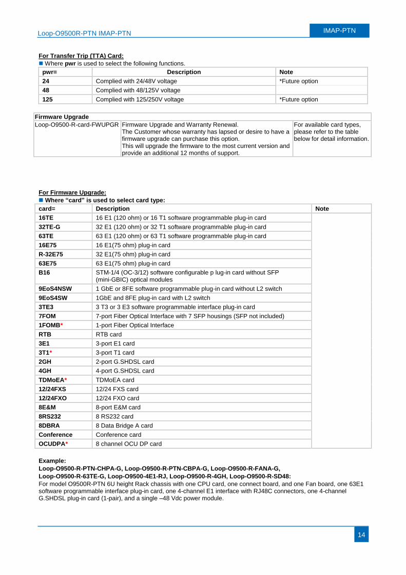
For Transfer Trip (TTA) Card:
Where pwr is used to select the following functions.
pwr= Description Note
24 Complied with 24/48V voltage *Future option
48 Complied with 48/125V voltage
125 Complied with 125/250V voltage *Future option
Firmware Upgrade
Loop-O9500-R-card-FWUPGR Firmware Upgrade and Warranty Renewal. The Customer whose warranty has lapsed or desire to have a firmware upgrade can purchase this option. This will upgrade the firmware to the most current version and provide an additional 12 months of support.
For available card types, please refer to the table below for detail information.
For Firmware Upgrade:
Where “card” is used to select card type:
card= Description Note
16TE 16 E1 (120 ohm) or 16 T1 software programmable plug-in card
32TE-G 32 E1 (120 ohm) or 32 T1 software programmable plug-in card
63TE 63 E1 (120 ohm) or 63 T1 software programmable plug-in card
16E75 16 E1(75 ohm) plug-in card
R-32E75 32 E1(75 ohm) plug-in card
63E75 63 E1(75 ohm) plug-in card
B16 STM-1/4 (OC-3/12) software configurable p lug-in card without SFP (mini-GBIC) optical modules
9EoS4NSW 1 GbE or 8FE software programmable plug-in card without L2 switch
9EoS4SW 1GbE and 8FE plug-in card with L2 switch
3TE3 3 T3 or 3 E3 software programmable interface plug-in card
7FOM 7-port Fiber Optical Interface with 7 SFP housings (SFP not included)
1FOMB* 1-port Fiber Optical Interface
RTB RTB card
3E1 3-port E1 card
3T1* 3-port T1 card
2GH 2-port G.SHDSL card
4GH 4-port G.SHDSL card
TDMoEA* TDMoEA card
12/24FXS 12/24 FXS card
12/24FXO 12/24 FXO card
8E&M 8-port E&M card
8RS232 8 RS232 card
8DBRA 8 Data Bridge A card
Conference Conference card
OCUDPA* 8 channel OCU DP card
Example:
Loop-O9500-R-PTN-CHPA-G, Loop-O9500-R-PTN-CBPA-G, Loop-O9500-R-FANA-G,
Loop-O9500-R-63TE-G, Loop-O9500-4E1-RJ, Loop-O9500-R-4GH, Loop-O9500-R-SD48:
For model O9500R-PTN 6U height Rack chassis with one CPU card, one connect board, and one Fan board, one 63E1 software programmable interface plug-in card, one 4-channel E1 interface with RJ48C connectors, one 4-channel G.SHDSL plug-in card (1-pair), and a single –48 Vdc power module.
Loop-O9500R-PTN IMAP-PTN IMAP-PTN
15
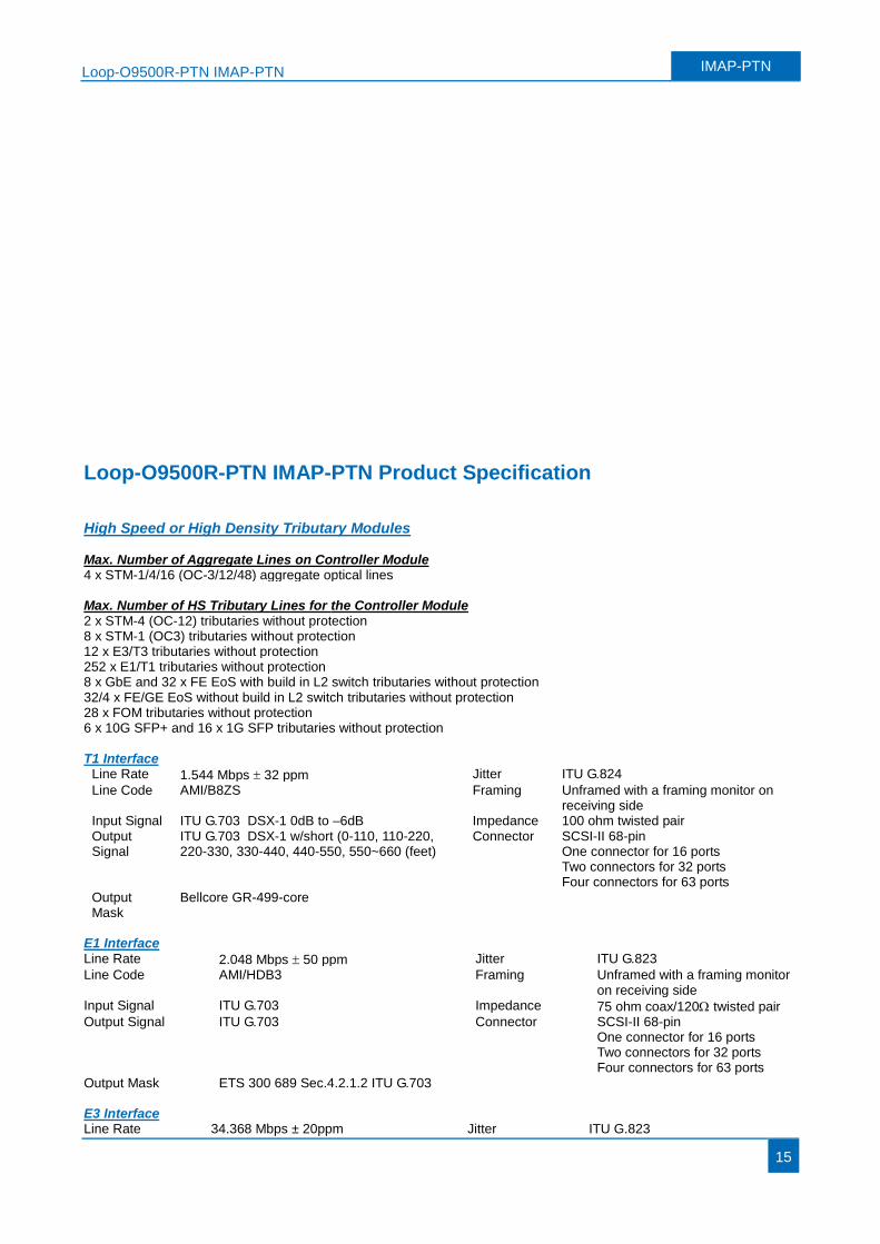
Loop-O9500R-PTN IMAP-PTN Product Specification High Speed or High Density Tributary Modules Max. Number of Aggregate Lines on Controller Module 4 x STM-1/4/16 (OC-3/12/48) aggregate optical lines Max. Number of HS Tributary Lines for the Controller Module 2 x STM-4 (OC-12) tributaries without protection 8 x STM-1 (OC3) tributaries without protection 12 x E3/T3 tributaries without protection 252 x E1/T1 tributaries without protection 8 x GbE and 32 x FE EoS with build in L2 switch tributaries without protection 32/4 x FE/GE EoS without build in L2 switch tributaries without protection 28 x FOM tributaries without protection 6 x 10G SFP+ and 16 x 1G SFP tributaries without protection T1 Interface
Line Rate 1.544 Mbps 32 ppm Jitter ITU G.824
Line Code AMI/B8ZS Framing Unframed with a framing monitor on receiving side
Input Signal ITU G.703 DSX-1 0dB to –6dB Impedance 100 ohm twisted pair Output Signal
ITU G.703 DSX-1 w/short (0-110, 110-220, 220-330, 330-440, 440-550, 550~660 (feet)
Connector SCSI-II 68-pin One connector for 16 ports Two connectors for 32 ports Four connectors for 63 ports
Output Mask
Bellcore GR-499-core
E1 Interface Line Rate 2.048 Mbps 50 ppm Jitter ITU G.823
Line Code AMI/HDB3 Framing Unframed with a framing monitor on receiving side
Input Signal ITU G.703 Impedance 75 ohm coax/120 twisted pair Output Signal ITU G.703 Connector SCSI-II 68-pin
One connector for 16 ports Two connectors for 32 ports Four connectors for 63 ports
Output Mask ETS 300 689 Sec.4.2.1.2 ITU G.703 E3 Interface Line Rate 34.368 Mbps ± 20ppm Jitter ITU G.823
Loop-O9500R-PTN IMAP-PTN IMAP-PTN
16
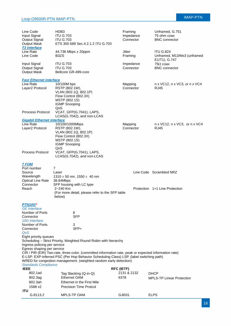
Line Code HDB3 Framing Unframed, G.751 Input Signal ITU G.703 Impedance 75 ohm coax Output Signal ITU G.703 Connector BNC connector Output Mask ETS 300 689 Sec.4.2.1.2 ITU G.703
T3 interface Line Rate 44.736 Mbps ± 20ppm Jitter ITU G.824 Line Code B3ZS Framing Unframed, M13/Mx3 (unframed
E1/T1), G.747 Input Signal ITU G.703 Impedance 75 coax Output Signal ITU G.703 Connector BNC connector Output Mask Bellcore GR-499-core
Fast Ethernet interface Line Rate 10/100M bps Mapping n x VC12, n x VC3, or n x VC4 Layer2 Protocol RSTP (802.1W), Connector RJ45
VLAN (802.1Q, 802.1P) Flow Control (802.3X) MSTP (802.1S) IGMP Snooping QoS
Prrocess Protocol VCAT, GFP(G.7041), LAPS, LCAS(G.7042), and non-LCAS
Gigabit Ethernet interface Line Rate 10/100/1000Mbps Mapping n x VC12, n x VC3, or n x VC4 Layer2 Protocol RSTP (802.1W), Connector RJ45
VLAN (802.1Q, 802.1P)
Flow Control (802.3X)
MSTP (802.1S)
IGMP Snooping
QoS
Process Protocol VCAT, GFP(G.7041), LAPS, LCAS(G.7042), and non-LCAS
7 FOM Port number 7 Source Laser Line Code Scrambled NRZ Wavelength 1310 50 nm, 1550 40 nm
Optical Line Rate 38.84Mbps Connector SFP housing with LC type Reach 2~240 Km
(For more detail, please refer to the SFP table below)
Protection 1+1 Line Protection
PTN10G* GE Interface Number of Ports 8 Connector SFP 10G Interface Number of Ports 3 Connector SFP+ QoS Eight priority queues Scheduling – Strict Priority, Weighted Round Robin with hierarchy Ingress policing per service Egress shaping per service CIR / PIR (EIR) Two-rate, three-color. (committed information rate, peak or expected information rate) E-LSP: EXP-Inferred PSC (Per Hop Behavior Scheduling Class) LSP. (label switching path) WRED for congestion management. (weighted random early detection) Standards Compliance IEEE RFC (IETF)
802.1ad Tag Stacking (Q-in-Q) 2131 & 2132 DHCP 802.3ag Ethernet OAM 6378 MPLS-TP Linear Protection 802.3ah Ethernet in the First Mile 1588 v2 Precision Time Protcol
ITU
G.8113.2 MPLS-TP OAM G.8031 ELPS
Loop-O9500R-PTN IMAP-PTN IMAP-PTN
17
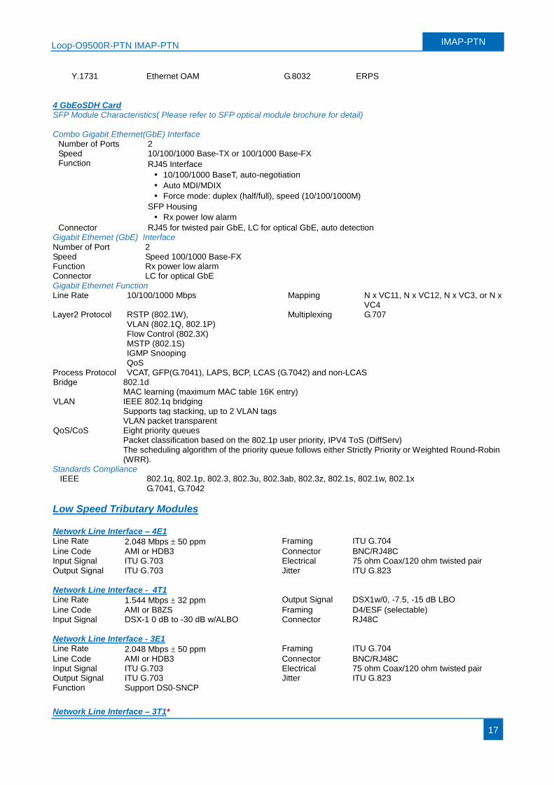
Y.1731 Ethernet OAM G.8032 ERPS 4 GbEoSDH Card SFP Module Characteristics( Please refer to SFP optical module brochure for detail) Combo Gigabit Ethernet(GbE) Interface
Number of Ports 2 Speed 10/100/1000 Base-TX or 100/1000 Base-FX Function RJ45 Interface
10/100/1000 BaseT, auto-negotiation
Auto MDI/MDIX
Force mode: duplex (half/full), speed (10/100/1000M)
SFP Housing
Rx power low alarm
Connector RJ45 for twisted pair GbE, LC for optical GbE, auto detection Gigabit Ethernet (GbE) Interface Number of Port 2 Speed Speed 100/1000 Base-FX Function Rx power low alarm Connector LC for optical GbE Gigabit Ethernet Function Line Rate 10/100/1000 Mbps Mapping N x VC11, N x VC12, N x VC3, or N x
VC4 Layer2 Protocol RSTP (802.1W), Multiplexing G.707
VLAN (802.1Q, 802.1P) Flow Control (802.3X)
MSTP (802.1S) IGMP Snooping QoS Process Protocol VCAT, GFP(G.7041), LAPS, BCP, LCAS (G.7042) and non-LCAS Bridge 802.1d MAC learning (maximum MAC table 16K entry) VLAN IEEE 802.1q bridging
Supports tag stacking, up to 2 VLAN tags VLAN packet transparent
QoS/CoS
Eight priority queues Packet classification based on the 802.1p user priority, IPV4 ToS (DiffServ) The scheduling algorithm of the priority queue follows either Strictly Priority or Weighted Round-Robin (WRR).
Standards Compliance IEEE 802.1q, 802.1p, 802.3, 802.3u, 802.3ab, 802.3z, 802.1s, 802.1w, 802.1x
G.7041, G.7042
Low Speed Tributary Modules Network Line Interface – 4E1 Line Rate 2.048 Mbps 50 ppm Framing ITU G.704
Line Code AMI or HDB3 Connector BNC/RJ48C Input Signal ITU G.703 Electrical 75 ohm Coax/120 ohm twisted pair Output Signal ITU G.703 Jitter ITU G.823 Network Line Interface - 4T1 Line Rate 1.544 Mbps 32 ppm Output Signal DSX1w/0, -7.5, -15 dB LBO
Line Code AMI or B8ZS Framing D4/ESF (selectable) Input Signal DSX-1 0 dB to -30 dB w/ALBO Connector RJ48C Network Line Interface - 3E1 Line Rate 2.048 Mbps 50 ppm Framing ITU G.704
Line Code AMI or HDB3 Connector BNC/RJ48C Input Signal ITU G.703 Electrical 75 ohm Coax/120 ohm twisted pair Output Signal ITU G.703 Jitter ITU G.823 Function Support DS0-SNCP
Network Line Interface – 3T1*
Loop-O9500R-PTN IMAP-PTN IMAP-PTN
18
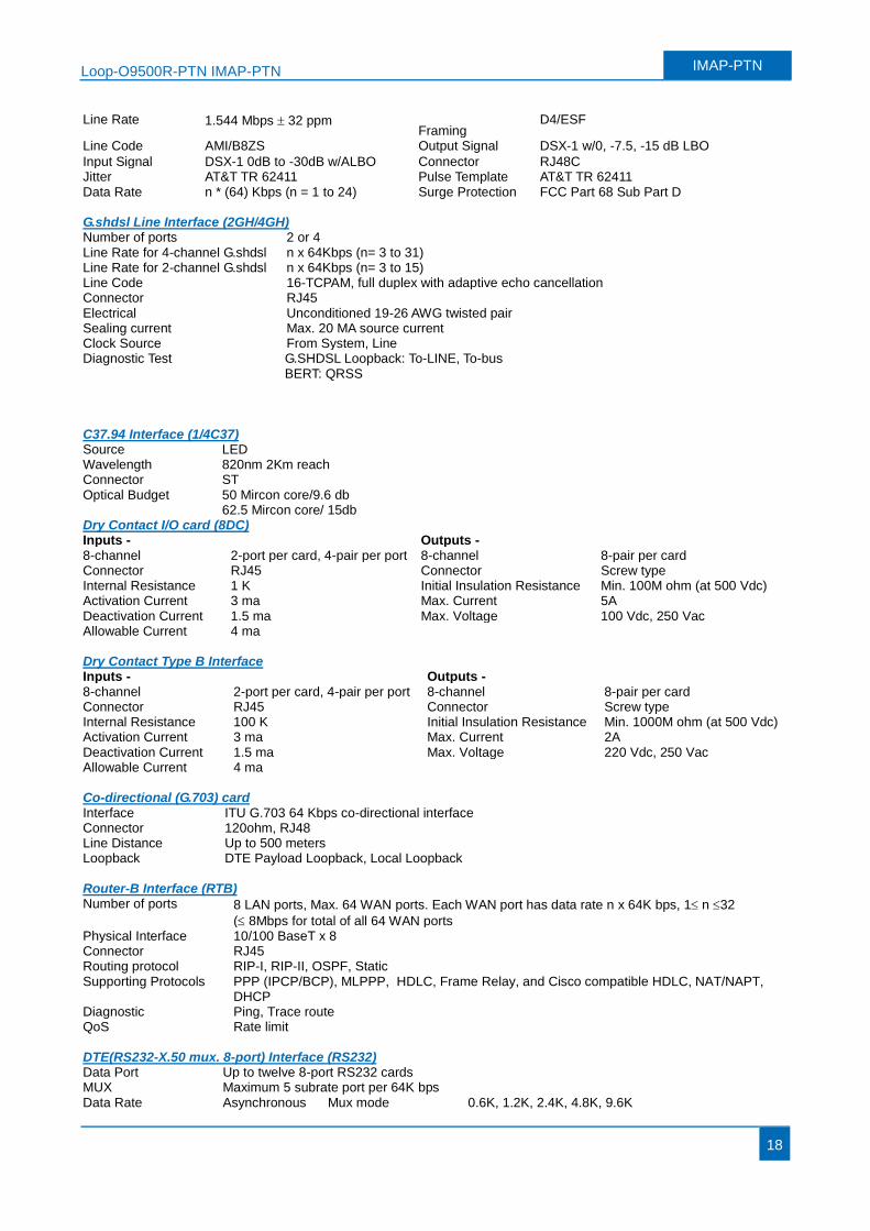
Line Rate 1.544 Mbps 32 ppm Framing
D4/ESF
Line Code AMI/B8ZS Output Signal DSX-1 w/0, -7.5, -15 dB LBO
Input Signal DSX-1 0dB to -30dB w/ALBO Connector RJ48C Jitter AT&T TR 62411 Pulse Template AT&T TR 62411 Data Rate
n * (64) Kbps (n = 1 to 24)
Surge Protection FCC Part 68 Sub Part D
G.shdsl Line Interface (2GH/4GH) Number of ports 2 or 4 Line Rate for 4-channel G.shdsl n x 64Kbps (n= 3 to 31) Line Rate for 2-channel G.shdsl n x 64Kbps (n= 3 to 15) Line Code 16-TCPAM, full duplex with adaptive echo cancellation Connector RJ45 Electrical Unconditioned 19-26 AWG twisted pair Sealing current Max. 20 MA source current Clock Source From System, Line Diagnostic Test G.SHDSL Loopback: To-LINE, To-bus
BERT: QRSS C37.94 Interface (1/4C37) Source LED Wavelength 820nm 2Km reach Connector ST Optical Budget 50 Mircon core/9.6 db
62.5 Mircon core/ 15db Dry Contact I/O card (8DC) Inputs - Outputs - 8-channel 2-port per card, 4-pair per port 8-channel 8-pair per card Connector RJ45 Connector Screw type Internal Resistance 1 K Initial Insulation Resistance Min. 100M ohm (at 500 Vdc) Activation Current 3 ma Max. Current 5A Deactivation Current 1.5 ma Max. Voltage 100 Vdc, 250 Vac Allowable Current 4 ma Dry Contact Type B Interface Inputs - Outputs - 8-channel 2-port per card, 4-pair per port 8-channel 8-pair per card Connector RJ45 Connector Screw type Internal Resistance 100 K Initial Insulation Resistance Min. 1000M ohm (at 500 Vdc) Activation Current 3 ma Max. Current 2A Deactivation Current 1.5 ma Max. Voltage 220 Vdc, 250 Vac Allowable Current 4 ma Co-directional (G.703) card Interface ITU G.703 64 Kbps co-directional interface Connector 120ohm, RJ48 Line Distance Up to 500 meters Loopback DTE Payload Loopback, Local Loopback Router-B Interface (RTB) Number of ports 8 LAN ports, Max. 64 WAN ports. Each WAN port has data rate n x 64K bps, 1 n 32
( 8Mbps for total of all 64 WAN ports Physical Interface 10/100 BaseT x 8 Connector RJ45 Routing protocol RIP-I, RIP-II, OSPF, Static Supporting Protocols PPP (IPCP/BCP), MLPPP, HDLC, Frame Relay, and Cisco compatible HDLC, NAT/NAPT,
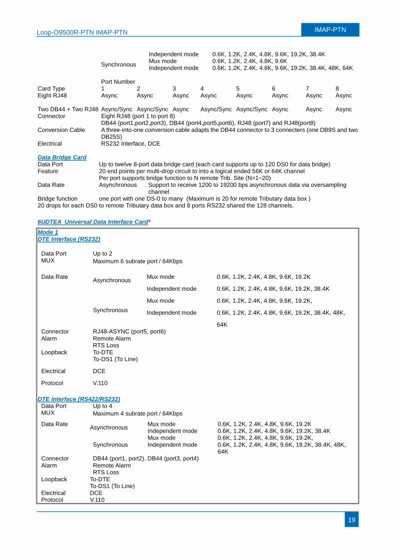
DHCP Diagnostic Ping, Trace route QoS Rate limit DTE(RS232-X.50 mux. 8-port) Interface (RS232) Data Port Up to twelve 8-port RS232 cards MUX Maximum 5 subrate port per 64K bps Data Rate Asynchronous Mux mode 0.6K, 1.2K, 2.4K, 4.8K, 9.6K
Loop-O9500R-PTN IMAP-PTN IMAP-PTN
19
Independent mode 0.6K, 1.2K, 2.4K, 4.8K, 9.6K, 19.2K, 38.4K
Synchronous Mux mode 0.6K, 1.2K, 2.4K, 4.8K, 9.6K Independent mode 0.6K, 1.2K, 2.4K, 4.8K, 9.6K, 19.2K, 38.4K, 48K, 64K
Card Type Port Number 1 2 3 4 5 6 7 8
Eight RJ48 Async Async Async Async Async Async Async Async Two DB44 + Two RJ48 Async/Sync Async/Sync Async Async/Sync Async/Sync Async Async Async Connector Eight RJ48 (port 1 to port 8)
DB44 (port1,port2,port3), DB44 (port4,port5,port6), RJ48 (port7) and RJ48(port8) Conversion Cable A three-into-one conversion cable adapts the DB44 connector to 3 connecters (one DB9S and two
DB25S) Electrical RS232 Interface, DCE Data Bridge Card Data Port Up to twelve 8-port data bridge card (each card supports up to 120 DS0 for data bridge) Feature 20 end points per multi-drop circuit to into a logical ended 56K or 64K channel
Per port supports bridge function to N remote Trib. Site (N=1~20) Data Rate Asynchronous Support to receive 1200 to 19200 bps asynchronous data via oversampling
channel Bridge function one port with one DS-0 to many (Maximum is 20 for remote Tributary data box ) 20 drops for each DS0 to remote Tributary data box and 8 ports RS232 shared the 128 channels.
6UDTEA Universal Data Interface Card*
Mode 1 DTE Interface (RS232)
Data Port Up to 2 MUX Maximum 6 subrate port / 64Kbps
Data Rate Asynchronous
Mux mode 0.6K, 1.2K, 2.4K, 4.8K, 9.6K, 19.2K
Independent mode 0.6K, 1.2K, 2.4K, 4.8K, 9.6K, 19.2K, 38.4K
Synchronous
Mux mode 0.6K, 1.2K, 2.4K, 4.8K, 9.6K, 19.2K,
Independent mode 0.6K, 1.2K, 2.4K, 4.8K, 9.6K, 19.2K, 38.4K, 48K,
64K Connector RJ48-ASYNC (port5, port6)
Alarm Remote Alarm RTS Loss
Loopback To-DTE To-DS1 (To Line)
Electrical
Protocol
DCE
V.110
DTE Interface (RS422/RS232)
Data Port Up to 4 MUX Maximum 4 subrate port / 64Kbps
Data Rate Asynchronous
Mux mode 0.6K, 1.2K, 2.4K, 4.8K, 9.6K, 19.2K Independent mode 0.6K, 1.2K, 2.4K, 4.8K, 9.6K, 19.2K, 38.4K
Synchronous Mux mode 0.6K, 1.2K, 2.4K, 4.8K, 9.6K, 19.2K, Independent mode 0.6K, 1.2K, 2.4K, 4.8K, 9.6K, 19.2K, 38.4K, 48K,
64K Connector DB44 (port1, port2), DB44 (port3, port4)
Alarm Remote Alarm RTS Loss
Loopback To-DTE To-DS1 (To Line)
Electrical Protocol
DCE V.110
Loop-O9500R-PTN IMAP-PTN IMAP-PTN
20
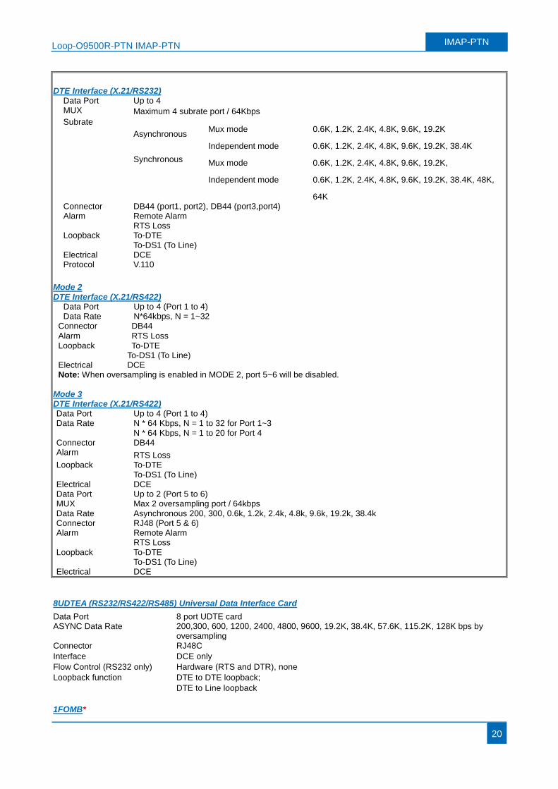
DTE Interface (X.21/RS232)
Data Port Up to 4 MUX Maximum 4 subrate port / 64Kbps
Subrate
Asynchronous Mux mode 0.6K, 1.2K, 2.4K, 4.8K, 9.6K, 19.2K
Independent mode 0.6K, 1.2K, 2.4K, 4.8K, 9.6K, 19.2K, 38.4K Synchronous Mux mode 0.6K, 1.2K, 2.4K, 4.8K, 9.6K, 19.2K,
Independent mode 0.6K, 1.2K, 2.4K, 4.8K, 9.6K, 19.2K, 38.4K, 48K,
64K Connector DB44 (port1, port2), DB44 (port3,port4) Alarm Remote Alarm
RTS Loss Loopback To-DTE
To-DS1 (To Line) Electrical Protocol
DCE V.110
Mode 2 DTE Interface (X.21/RS422)
Data Port Up to 4 (Port 1 to 4) Data Rate N*64kbps, N = 1~32
Connector DB44
Alarm Loopback
RTS Loss To-DTE
To-DS1 (To Line) Electrical DCE Note: When oversampling is enabled in MODE 2, port 5~6 will be disabled.
Mode 3 DTE Interface (X.21/RS422) Data Port Up to 4 (Port 1 to 4) Data Rate N * 64 Kbps, N = 1 to 32 for Port 1~3
N * 64 Kbps, N = 1 to 20 for Port 4 Connector DB44 Alarm RTS Loss Loopback To-DTE
To-DS1 (To Line) Electrical Data Port MUX Data Rate Connector Alarm Loopback Electrical
DCE Up to 2 (Port 5 to 6) Max 2 oversampling port / 64kbps Asynchronous 200, 300, 0.6k, 1.2k, 2.4k, 4.8k, 9.6k, 19.2k, 38.4k RJ48 (Port 5 & 6) Remote Alarm RTS Loss To-DTE To-DS1 (To Line) DCE
8UDTEA (RS232/RS422/RS485) Universal Data Interface Card
Data Port 8 port UDTE card ASYNC Data Rate 200,300, 600, 1200, 2400, 4800, 9600, 19.2K, 38.4K, 57.6K, 115.2K, 128K bps by
oversampling Connector RJ48C
Interface DCE only
Flow Control (RS232 only) Hardware (RTS and DTR), none
Loopback function DTE to DTE loopback;
DTE to Line loopback
1FOMB*
Loop-O9500R-PTN IMAP-PTN IMAP-PTN
21
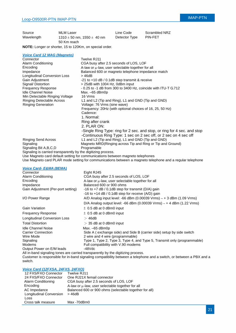
Source MLM Laser Line Code Scrambled NRZ
Wavelength 1310 50 nm, 1550 40 nm Detector Type PIN-FET
50 Km reach
NOTE: Longer or shorter, 15 to 120Km, on special order. Voice Card 12 MAG (Magneto) Connector Twelve RJ11 Alarm Conditioning CGA busy after 2.5 seconds of LOS, LOF Encoding A-law or -law, user selectable together for all Impedance Balanced 600 or magneto telephone impedance match Longitudinal Conversion Loss > 46dB
Gain Adjustment -21 to +10 dB / 0.1dB step transmit & receive Signal/ Distortion > 25dB with 1004 Hz, 0dBm input Frequency Response - 0.25 to -1 dB from 300 to 3400 Hz, coincide with ITU-T G.712 Idle Channel Noise Max. –65 dBm0p Min Detectable Ringing Voltage 16 Vrms Ringing Detectable Across L1 and L2 (Tip and Ring), L1 and GND (Tip and GND) Ringing Generation Voltage: 76 Vrms (sine wave)
Frequency: 20Hz (with optional choices of 16, 25, 50 Hz) Cadence:
1. Normal: Ring after crank 2. PLAR ON: -Single Ring Type: ring for 2 sec. and stop, or ring for 4 sec. and stop -Continuous Ring Type: 1 sec on 2 sec off, or 2 sec on 4 sec off
Ringing Send Across L1 and L2 (Tip and Ring), L1 and GND (Tip and GND) Signaling Magneto MRD(Ringing across Tip and Ring or Tip and Ground) Signaling Bit A,B,C,D Programable Signaling is carried transparently by the digitizing process. Use Magneto card default setting for communications between magneto telephones Use Magneto card PLAR mode setting for communications between a magneto telephone and a regular telephone Voice Card- E&MA (8EMA) Connector Eight RJ45 Alarm Conditioning CGA busy after 2.5 seconds of LOS, LOF Encoding A-law or -law, user selectable together for all Impedance Balanced 600 or 900 ohms Gain Adjustment (Per-port setting) -16 to +7 dB / 0.1dB step for transmit (D/A) gain
-16 to +14 dB / 0.1dB step for receive (A/D) gain
I/O Power Range A/D Analog input level: -66 dBm (0.00039 Vrms) ~ + 3 dBm (1.09 Vrms)
D/A Analog output level: -66 dBm (0.00039 Vrms) ~ + 4 dBm (1.22 Vrms)
Gain Variation ± 0.5 dB at 0 dBm0 input
Frequency Response ± 0.5 dB at 0 dBm0 input
Longitudinal Conversion Loss > 46dB
Total Distortion > 35 dB at 0 dBm0 input
Idle Channel Noise Max. –65 dBm0p Carrier Connection Side A ( exchange side) and Side B (carrier side) setup by side switch Wire Mode 2 wire and 4 wire (programmable) Signaling Type 1, Type 2, Type 3, Type 4, and Type 5, Transmit only (programmable) Modems Full compatibility with V.90 modems Output Power on E/M leads -48Vdc All in-band signaling tones are carried transparently by the digitizing process. Customer is responsible for in-band signaling compatibility between a telephone and a switch, or between a PBX and a switch. Voice Card (12FXSA, 24FXS, 24FXO)
12 FXS/FXO Connector Twelve RJ11 24 FXS/FXO Connector One RJ21X femail connector Alarm Conditioning CGA busy after 2.5 seconds of LOS, LOF Encoding A-law or -law, user selectable together for all AC Impedance Balanced 600 or 900 ohms (selectable together for all) Longitudinal Conversion Loss
> 46dB
Cross talk measure Max -70dBm0
Loop-O9500R-PTN IMAP-PTN IMAP-PTN
22
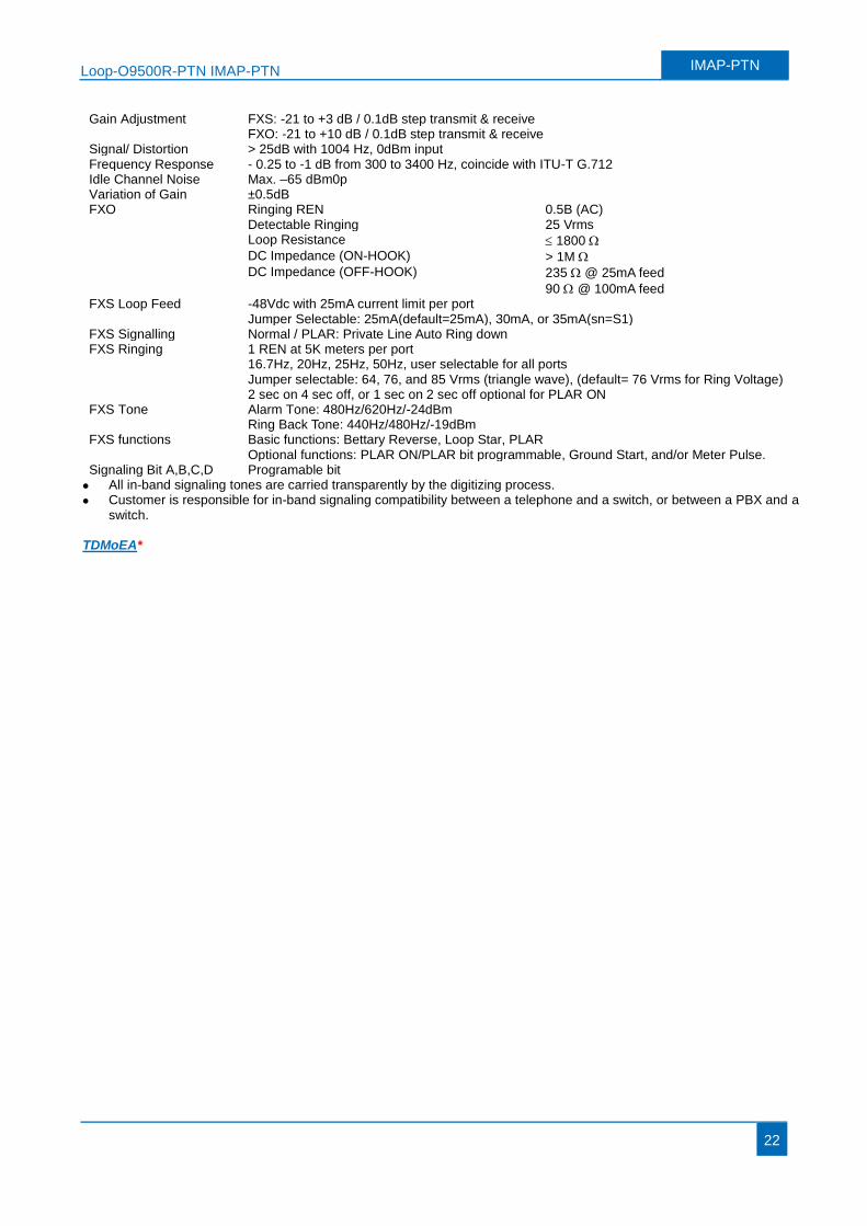
Gain Adjustment FXS: -21 to +3 dB / 0.1dB step transmit & receive FXO: -21 to +10 dB / 0.1dB step transmit & receive
Signal/ Distortion > 25dB with 1004 Hz, 0dBm input Frequency Response - 0.25 to -1 dB from 300 to 3400 Hz, coincide with ITU-T G.712 Idle Channel Noise Max. –65 dBm0p Variation of Gain ±0.5dB FXO Ringing REN 0.5B (AC)
Detectable Ringing 25 Vrms Loop Resistance 1800 DC Impedance (ON-HOOK) > 1M DC Impedance (OFF-HOOK) 235 @ 25mA feed 90 @ 100mA feed FXS Loop Feed -48Vdc with 25mA current limit per port
Jumper Selectable: 25mA(default=25mA), 30mA, or 35mA(sn=S1) FXS Signalling Normal / PLAR: Private Line Auto Ring down FXS Ringing 1 REN at 5K meters per port
16.7Hz, 20Hz, 25Hz, 50Hz, user selectable for all ports Jumper selectable: 64, 76, and 85 Vrms (triangle wave), (default= 76 Vrms for Ring Voltage) 2 sec on 4 sec off, or 1 sec on 2 sec off optional for PLAR ON FXS Tone Alarm Tone: 480Hz/620Hz/-24dBm
Ring Back Tone: 440Hz/480Hz/-19dBm FXS functions Basic functions: Bettary Reverse, Loop Star, PLAR
Optional functions: PLAR ON/PLAR bit programmable, Ground Start, and/or Meter Pulse. Signaling Bit A,B,C,D Programable bit
All in-band signaling tones are carried transparently by the digitizing process. Customer is responsible for in-band signaling compatibility between a telephone and a switch, or between a PBX and a
switch. TDMoEA*
Loop-O9500R-PTN IMAP-PTN IMAP-PTN
23
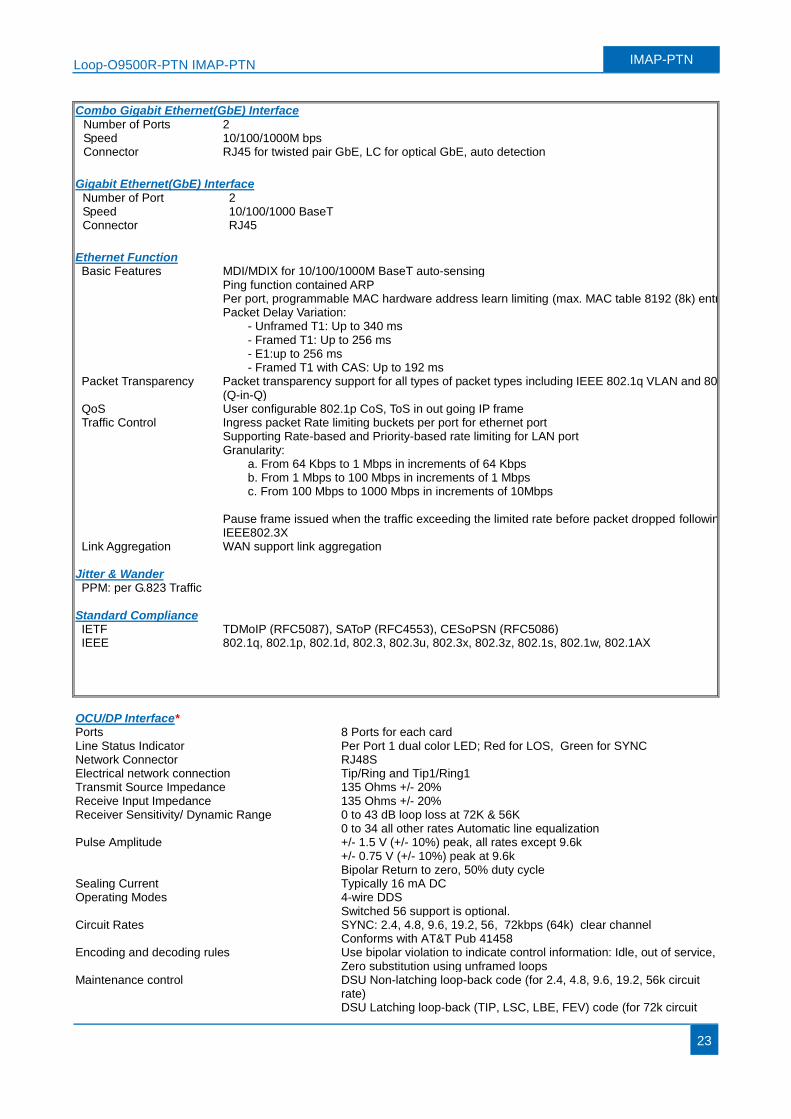
Combo Gigabit Ethernet(GbE) Interface Number of Ports 2 Speed 10/100/1000M bps Connector RJ45 for twisted pair GbE, LC for optical GbE, auto detection
Gigabit Ethernet(GbE) Interface
Number of Port 2 Speed 10/100/1000 BaseT Connector RJ45
Ethernet Function Basic Features MDI/MDIX for 10/100/1000M BaseT auto-sensing
Ping function contained ARP Per port, programmable MAC hardware address learn limiting (max. MAC table 8192 (8k) entry) Packet Delay Variation:
- Unframed T1: Up to 340 ms - Framed T1: Up to 256 ms - E1:up to 256 ms - Framed T1 with CAS: Up to 192 ms
Packet Transparency Packet transparency support for all types of packet types including IEEE 802.1q VLAN and 802.1ad (Q-in-Q)
QoS User configurable 802.1p CoS, ToS in out going IP frame Traffic Control Ingress packet Rate limiting buckets per port for ethernet port
Supporting Rate-based and Priority-based rate limiting for LAN port Granularity:
a. From 64 Kbps to 1 Mbps in increments of 64 Kbps b. From 1 Mbps to 100 Mbps in increments of 1 Mbps c. From 100 Mbps to 1000 Mbps in increments of 10Mbps
Pause frame issued when the traffic exceeding the limited rate before packet dropped following IEEE802.3X
Link Aggregation WAN support link aggregation Jitter & Wander PPM: per G.823 Traffic
Standard Compliance IETF TDMoIP (RFC5087), SAToP (RFC4553), CESoPSN (RFC5086) IEEE 802.1q, 802.1p, 802.1d, 802.3, 802.3u, 802.3x, 802.3z, 802.1s, 802.1w, 802.1AX
OCU/DP Interface* Ports 8 Ports for each card Line Status Indicator Per Port 1 dual color LED; Red for LOS, Green for SYNC Network Connector RJ48S Electrical network connection Tip/Ring and Tip1/Ring1 Transmit Source Impedance 135 Ohms +/- 20% Receive Input Impedance 135 Ohms +/- 20% Receiver Sensitivity/ Dynamic Range 0 to 43 dB loop loss at 72K & 56K
0 to 34 all other rates Automatic line equalization Pulse Amplitude +/- 1.5 V (+/- 10%) peak, all rates except 9.6k
+/- 0.75 V (+/- 10%) peak at 9.6k Bipolar Return to zero, 50% duty cycle
Sealing Current Typically 16 mA DC Operating Modes 4-wire DDS
Switched 56 support is optional. Circuit Rates SYNC: 2.4, 4.8, 9.6, 19.2, 56, 72kbps (64k) clear channel
Conforms with AT&T Pub 41458 Encoding and decoding rules Use bipolar violation to indicate control information: Idle, out of service,
Zero substitution using unframed loops Maintenance control
DSU Non-latching loop-back code (for 2.4, 4.8, 9.6, 19.2, 56k circuit rate) DSU Latching loop-back (TIP, LSC, LBE, FEV) code (for 72k circuit
Loop-O9500R-PTN IMAP-PTN IMAP-PTN
24
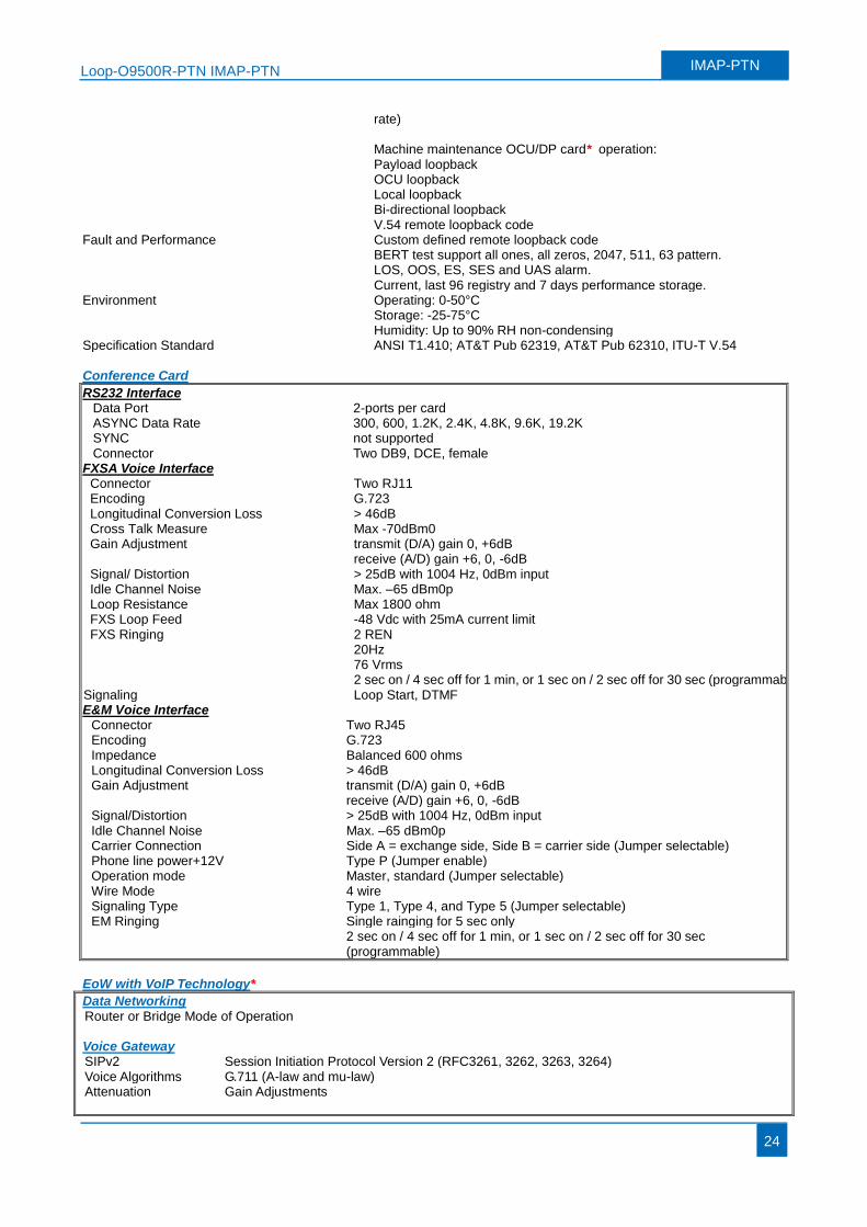
Fault and Performance
rate) Machine maintenance OCU/DP card* operation: Payload loopback OCU loopback Local loopback Bi-directional loopback V.54 remote loopback code Custom defined remote loopback code BERT test support all ones, all zeros, 2047, 511, 63 pattern. LOS, OOS, ES, SES and UAS alarm. Current, last 96 registry and 7 days performance storage.
Environment Operating: 0-50°C Storage: -25-75°C Humidity: Up to 90% RH non-condensing
Specification Standard ANSI T1.410; AT&T Pub 62319, AT&T Pub 62310, ITU-T V.54 Conference Card
RS232 Interface Data Port 2-ports per card ASYNC Data Rate 300, 600, 1.2K, 2.4K, 4.8K, 9.6K, 19.2K SYNC not supported Connector Two DB9, DCE, female
FXSA Voice Interface Connector Two RJ11 Encoding G.723 Longitudinal Conversion Loss > 46dB Cross Talk Measure Max -70dBm0 Gain Adjustment transmit (D/A) gain 0, +6dB
receive (A/D) gain +6, 0, -6dB Signal/ Distortion > 25dB with 1004 Hz, 0dBm input Idle Channel Noise Max. –65 dBm0p Loop Resistance Max 1800 ohm FXS Loop Feed -48 Vdc with 25mA current limit FXS Ringing 2 REN
20Hz 76 Vrms 2 sec on / 4 sec off for 1 min, or 1 sec on / 2 sec off for 30 sec (programmable)
Signaling Loop Start, DTMF E&M Voice Interface
Connector Two RJ45 Encoding G.723 Impedance Balanced 600 ohms Longitudinal Conversion Loss > 46dB Gain Adjustment transmit (D/A) gain 0, +6dB
receive (A/D) gain +6, 0, -6dB Signal/Distortion > 25dB with 1004 Hz, 0dBm input Idle Channel Noise Max. –65 dBm0p Carrier Connection Side A = exchange side, Side B = carrier side (Jumper selectable) Phone line power+12V Type P (Jumper enable) Operation mode Master, standard (Jumper selectable) Wire Mode 4 wire Signaling Type Type 1, Type 4, and Type 5 (Jumper selectable) EM Ringing Single rainging for 5 sec only
2 sec on / 4 sec off for 1 min, or 1 sec on / 2 sec off for 30 sec (programmable)
EoW with VoIP Technology*
Data Networking Router or Bridge Mode of Operation Voice Gateway SIPv2 Session Initiation Protocol Version 2 (RFC3261, 3262, 3263, 3264) Voice Algorithms G.711 (A-law and mu-law) Attenuation Gain Adjustments
Loop-O9500R-PTN IMAP-PTN IMAP-PTN
25
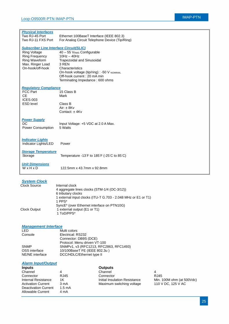
Physical Interfaces Two RJ-45 Port Ethernet 100BaseT Interface (IEEE 802.3) Two RJ-11 FXS Port For Analog Circuit Telephone Device (Tip/Ring) Subscriber Line Interface Circuit(SLIC)
Regulatory Compliance FCC Part 15 Class B CE Mark ICES-003 ESD level Class B
Air: ± 8Kv Contact: ± 4Kv
Power Supply DC Input Voltage: +5 VDC at 2.0 A Max. Power Consumption 5 Watts Indicator Lights Indicator Lights/LED Power Storage Temperature Storage Temperature -13°F to 185°F (-25°C to 85°C)
Unit Dimensions W x H x D 122.5mm x 43.7mm x 92.8mm
Ring Voltage 40 – 55 VRMS Configurable Ring Frequency 10Hz – 40Hz Ring Waveform Trapezoidal and Sinusoidal Max. Ringer Load 3 REN On-hook/off-hook Characteristics On-hook voltage (tip/ring) : -50 V NOMINAL Off-hook current : 20 mA min Terminating Impedance : 600 ohms
System Clock
Clock Source
Internal clock 4 aggregate lines clocks (STM-1/4 (OC-3/12)) 6 tributary clocks 1 external input clocks (ITU-T G.703 - 2.048 MHz or E1 or T1) 1 PPS* SyncE* (over Ethernet interface on PTN10G)
Clock Output 1 external output (E1 or T1) 1 ToD/PPS*
Management Interface LED Multi colors Console Electrical: RS232 Connector: DB9S (DCE) Protocol: Menu driven VT-100 SNMP SNMPv1, v3 (RFC1213, RFC2863, RFC1493) OSS interface 10/100BaseT FE (IEEE 802.3u ) NE/NE interface DCC/HDLC/Ethernet type II
Alarm Input/Output Inputs Outputs
Channel 4 Channel 4 Connector RJ45 Connector RJ45 Internal Resistance 1K Initial Insulation Resistance Min. 100M ohm (at 500Vdc) Activation Current 3 mA Maximum switching voltage 110 V DC, 125 V AC Deactivation Current 1.5 mA Allowable Current 4 mA
Loop-O9500R-PTN IMAP-PTN IMAP-PTN
26
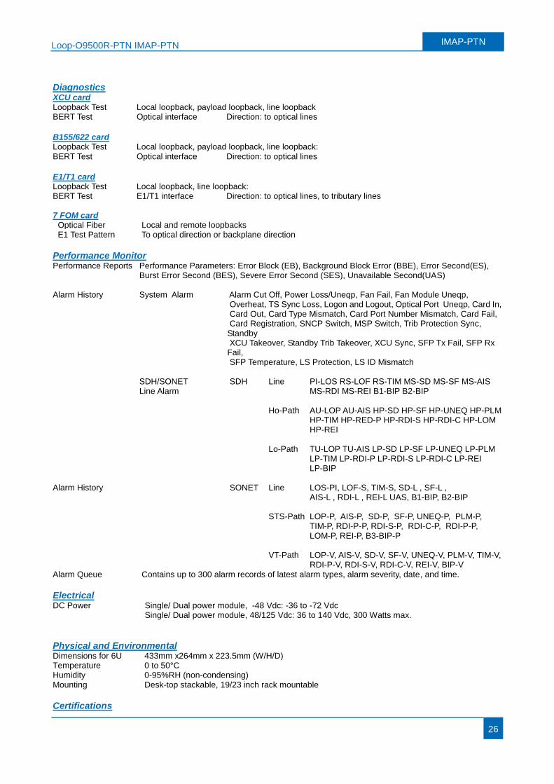
Diagnostics XCU card Loopback Test Local loopback, payload loopback, line loopback BERT Test Optical interface Direction: to optical lines
B155/622 card Loopback Test Local loopback, payload loopback, line loopback: BERT Test Optical interface Direction: to optical lines
E1/T1 card Loopback Test Local loopback, line loopback: BERT Test E1/T1 interface Direction: to optical lines, to tributary lines 7 FOM card
Optical Fiber Local and remote loopbacks E1 Test Pattern To optical direction or backplane direction
Performance Monitor Performance Reports Performance Parameters: Error Block (EB), Background Block Error (BBE), Error Second(ES),
Burst Error Second (BES), Severe Error Second (SES), Unavailable Second(UAS) Alarm History Alarm History
System Alarm Alarm Cut Off, Power Loss/Uneqp, Fan Fail, Fan Module Uneqp, Overheat, TS Sync Loss, Logon and Logout, Optical Port Uneqp, Card In, Card Out, Card Type Mismatch, Card Port Number Mismatch, Card Fail, Card Registration, SNCP Switch, MSP Switch, Trib Protection Sync, Standby XCU Takeover, Standby Trib Takeover, XCU Sync, SFP Tx Fail, SFP Rx Fail, SFP Temperature, LS Protection, LS ID Mismatch
SDH/SONET Line Alarm
SDH Line PI-LOS RS-LOF RS-TIM MS-SD MS-SF MS-AIS MS-RDI MS-REI B1-BIP B2-BIP
Ho-Path AU-LOP AU-AIS HP-SD HP-SF HP-UNEQ HP-PLM HP-TIM HP-RED-P HP-RDI-S HP-RDI-C HP-LOM HP-REI
Lo-Path TU-LOP TU-AIS LP-SD LP-SF LP-UNEQ LP-PLM
LP-TIM LP-RDI-P LP-RDI-S LP-RDI-C LP-REI LP-BIP
SONET Line LOS-PI, LOF-S, TIM-S, SD-L , SF-L ,
AIS-L , RDI-L , REI-L UAS, B1-BIP, B2-BIP STS-Path LOP-P, AIS-P, SD-P, SF-P, UNEQ-P, PLM-P,
TIM-P, RDI-P-P, RDI-S-P, RDI-C-P, RDI-P-P, LOM-P, REI-P, B3-BIP-P
VT-Path LOP-V, AIS-V, SD-V, SF-V, UNEQ-V, PLM-V, TIM-V,
RDI-P-V, RDI-S-V, RDI-C-V, REI-V, BIP-V Alarm Queue Contains up to 300 alarm records of latest alarm types, alarm severity, date, and time.
Electrical DC Power Single/ Dual power module, -48 Vdc: -36 to -72 Vdc
Single/ Dual power module, 48/125 Vdc: 36 to 140 Vdc, 300 Watts max.
Physical and Environmental Dimensions for 6U 433mm x264mm x 223.5mm (W/H/D) Temperature 0 to 50°C Humidity 0-95%RH (non-condensing) Mounting Desk-top stackable, 19/23 inch rack mountable
Certifications
Loop-O9500R-PTN IMAP-PTN IMAP-PTN
27
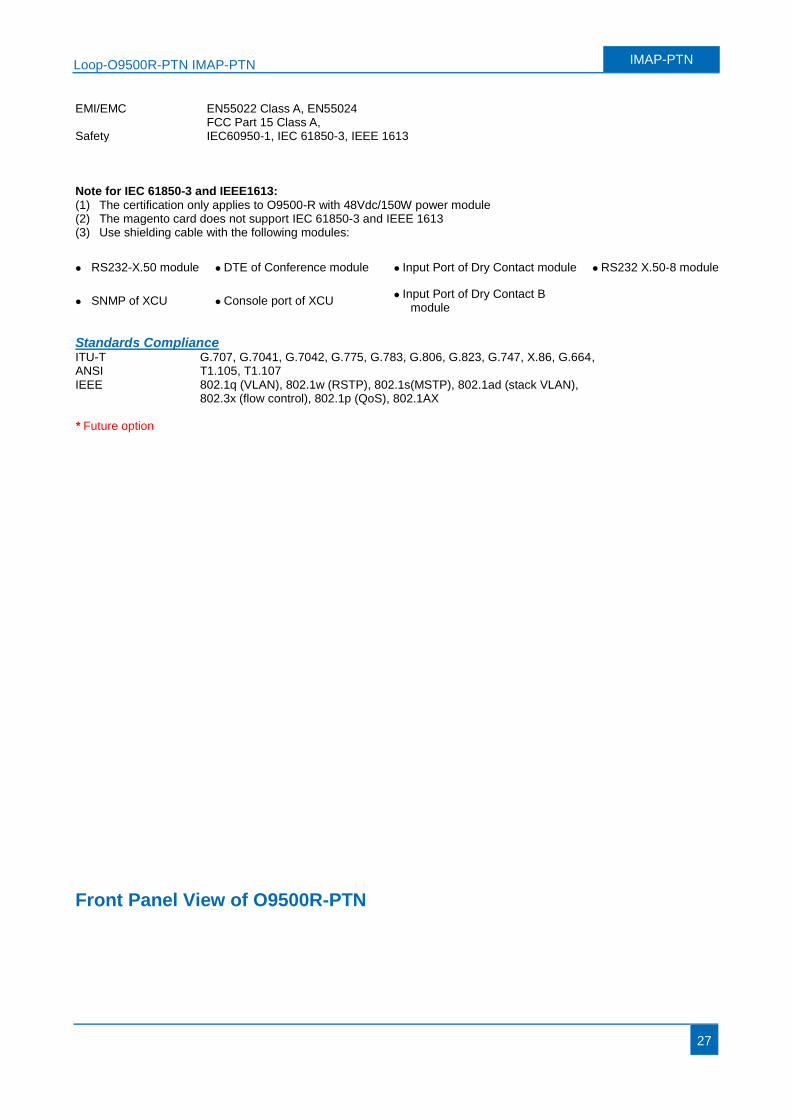
EMI/EMC EN55022 Class A, EN55024 FCC Part 15 Class A,
Safety IEC60950-1, IEC 61850-3, IEEE 1613 Note for IEC 61850-3 and IEEE1613: (1) The certification only applies to O9500-R with 48Vdc/150W power module (2) The magento card does not support IEC 61850-3 and IEEE 1613 (3) Use shielding cable with the following modules:
RS232-X.50 module DTE of Conference module Input Port of Dry Contact module RS232 X.50-8 module
SNMP of XCU Console port of XCU Input Port of Dry Contact B
module
Standards Compliance ITU-T G.707, G.7041, G.7042, G.775, G.783, G.806, G.823, G.747, X.86, G.664, ANSI T1.105, T1.107 IEEE 802.1q (VLAN), 802.1w (RSTP), 802.1s(MSTP), 802.1ad (stack VLAN),
802.3x (flow control), 802.1p (QoS), 802.1AX * Future option
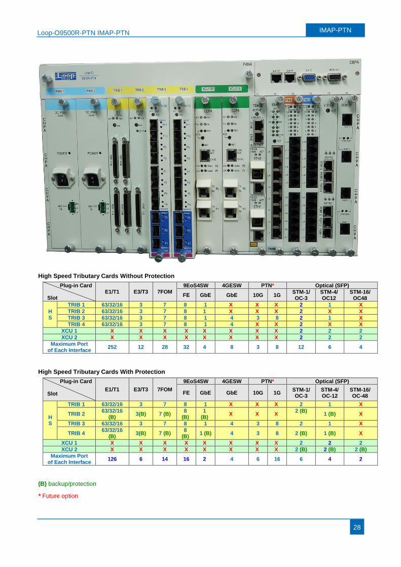
Front Panel View of O9500R-PTN
Loop-O9500R-PTN IMAP-PTN IMAP-PTN
28
High Speed Tributary Cards Without Protection
Plug-in Card
Slot E1/T1 E3/T3 7FOM
9EoS4SW 4GESW PTN* Optical (SFP)
FE GbE GbE 10G 1G STM-1/ OC-3
STM-4/ OC12
STM-16/ OC48
HS
TRIB 1 63/32/16 3 7 8 1 X X X 2 1 X
TRIB 2 63/32/16 3 7 8 1 X X X 2 X X
TRIB 3 63/32/16 3 7 8 1 4 3 8 2 1 X
TRIB 4 63/32/16 3 7 8 1 4 X X 2 X X
XCU 1 X X X X X X X X 2 2 2
XCU 2 X X X X X X X X 2 2 2
Maximum Port of Each Interface
252 12 28 32 4 8 3 8 12 6 4
High Speed Tributary Cards With Protection
Plug-in Card
Slot E1/T1 E3/T3 7FOM
9EoS4SW 4GESW PTN* Optical (SFP)
FE GbE GbE 10G 1G STM-1/ OC-3
STM-4/ OC-12
STM-16/ OC-48
HS
TRIB 1 63/32/16 3 7 8 1 X X X 2 1 X
TRIB 2 63/32/16
(B) 3(B) 7 (B)
8 (B)
1 (B)
X X X 2 (B)
1 (B) X
TRIB 3 63/32/16 3 7 8 1 4 3 8 2 1 X
TRIB 4 63/32/16
(B) 3(B) 7 (B)
8 (B)
1 (B) 4 3 8 2 (B) 1 (B) X
XCU 1 X X X X X X X X 2 2 2
XCU 2 X X X X X X X X 2 (B) 2 (B) 2 (B)
Maximum Port of Each Interface
126 6 14 16 2 4 6 16 6 4 2
(B) backup/protection
* Future option
Loop-O9500R-PTN IMAP-PTN IMAP-PTN
29
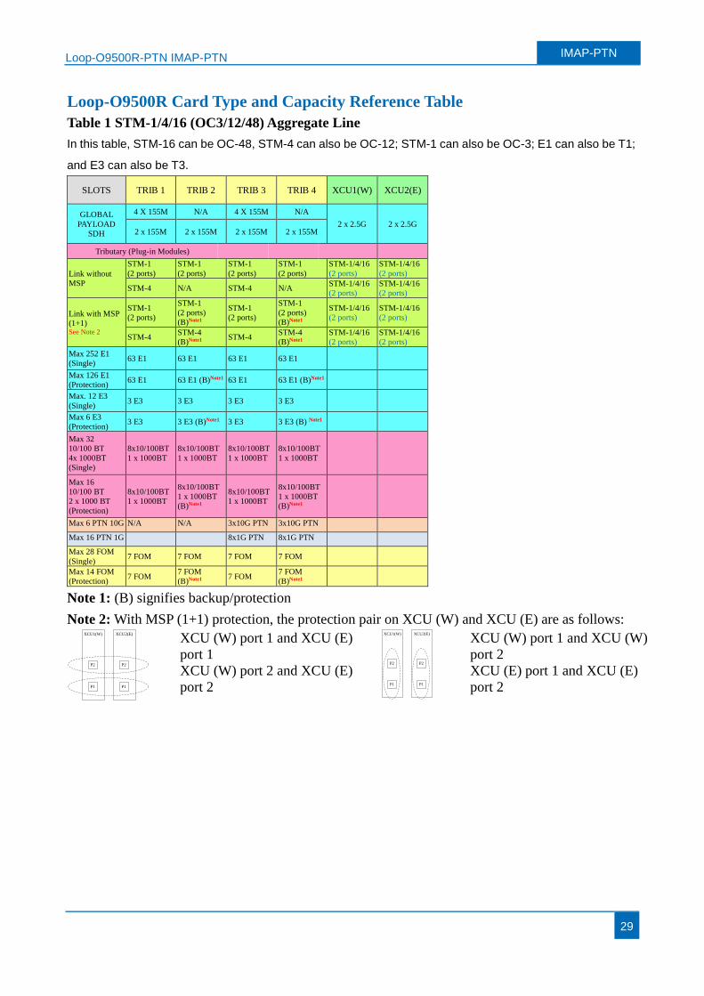
Loop-O9500R Card Type and Capacity Reference Table
Table 1 STM-1/4/16 (OC3/12/48) Aggregate Line
In this table, STM-16 can be OC-48, STM-4 can also be OC-12; STM-1 can also be OC-3; E1 can also be T1;
and E3 can also be T3.
SLOTS TRIB 1 TRIB 2 TRIB 3 TRIB 4 XCU1(W) XCU2(E)
GLOBAL
PAYLOAD
SDH
4 X 155M N/A 4 X 155M N/A
2 x 2.5G 2 x 2.5G 2 x 155M 2 x 155M 2 x 155M 2 x 155M
Tributary (Plug-in Modules)
Link without
MSP
STM-1
(2 ports)
STM-1
(2 ports)
STM-1
(2 ports)
STM-1
(2 ports)
STM-1/4/16
(2 ports)
STM-1/4/16
(2 ports)
STM-4 N/A STM-4 N/A STM-1/4/16
(2 ports)
STM-1/4/16
(2 ports)
Link with MSP
(1+1) See Note 2
STM-1
(2 ports)
STM-1
(2 ports)
(B)Note1
STM-1
(2 ports)
STM-1
(2 ports)
(B)Note1
STM-1/4/16
(2 ports)
STM-1/4/16
(2 ports)
STM-4 STM-4
(B)Note1 STM-4
STM-4
(B)Note1
STM-1/4/16
(2 ports)
STM-1/4/16
(2 ports)
Max 252 E1
(Single) 63 E1 63 E1 63 E1 63 E1
Max 126 E1
(Protection) 63 E1 63 E1 (B)Note1 63 E1 63 E1 (B)Note1
Max. 12 E3
(Single) 3 E3 3 E3 3 E3 3 E3
Max 6 E3
(Protection) 3 E3 3 E3 (B)Note1 3 E3 3 E3 (B) Note1
Max 32
10/100 BT
4x 1000BT
(Single)
8x10/100BT
1 x 1000BT
8x10/100BT
1 x 1000BT
8x10/100BT
1 x 1000BT
8x10/100BT
1 x 1000BT
Max 16
10/100 BT
2 x 1000 BT
(Protection)
8x10/100BT
1 x 1000BT
8x10/100BT
1 x 1000BT
(B)Note1
8x10/100BT
1 x 1000BT
8x10/100BT
1 x 1000BT
(B)Note1
Max 6 PTN 10G N/A N/A 3x10G PTN 3x10G PTN
Max 16 PTN 1G 8x1G PTN 8x1G PTN
Max 28 FOM
(Single) 7 FOM 7 FOM 7 FOM 7 FOM
Max 14 FOM
(Protection) 7 FOM
7 FOM
(B)Note1 7 FOM
7 FOM
(B)Note1
Note 1: (B) signifies backup/protection
Note 2: With MSP (1+1) protection, the protection pair on XCU (W) and XCU (E) are as follows: XCU1(W) XCU2(E)
P1
P2 P2
P1
XCU (W) port 1 and XCU (E)
port 1
XCU (W) port 2 and XCU (E)
port 2
XCU1(W) XCU2(E)
P1
P2 P2
P1
XCU (W) port 1 and XCU (W)
port 2
XCU (E) port 1 and XCU (E)
port 2
Loop-O9500R-PTN IMAP-PTN IMAP-PTN
30
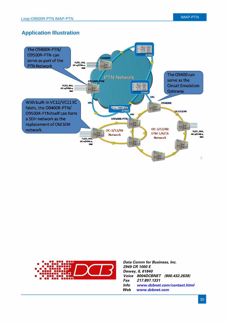
Application Illustration
Info www.dcbnet.com/contact.htmlFax 217.897.1331Voice 8004DCBNET (800.432.2638)Dewey, IL 618402949 CR 1000 EData Comm for Business, Inc.
Web www.dcbnet.com


