Download - Low Pressure Filter Pi 2000/Pi 2200 - BIBUS
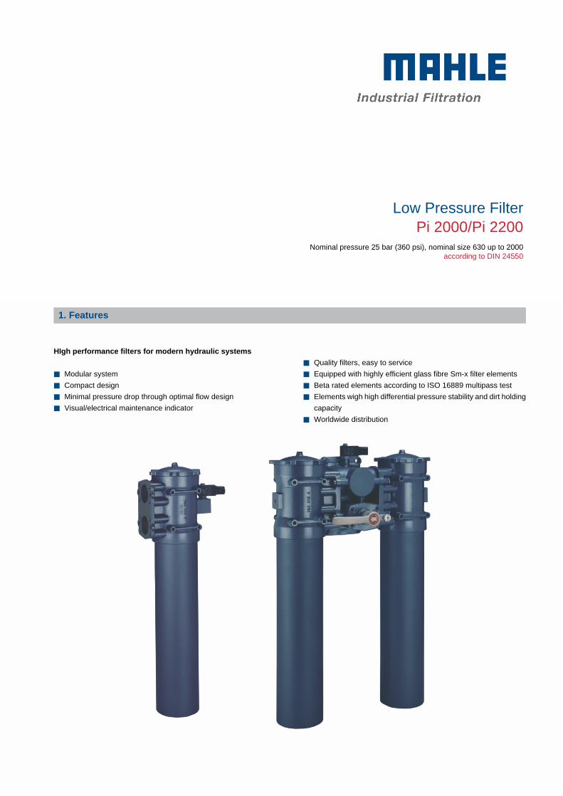
Low Pressure FilterPi 2000/Pi 2200
Nominal pressure 25 bar (360 psi), nominal size 630 up to 2000according to DIN 24550
1. Features.:
.
HIgh performance filters for modern hydraulic systems
.
■ Modular system
■ Compact design
■ Minimal pressure drop through optimal flow design
■ Visual/electrical maintenance indicator
.
.
-
■ Quality filters, easy to service
■ Equipped with highly efficient glass fibre Sm-x filter elements
■ Beta rated elements according to ISO 16889 multipass test
■ Elements wigh high differential pressure stability and dirt holding
capacity
■ Worldwide distribution
Low Pressure Filter Pi 2000/Pi 2200 NG 630-2000 2
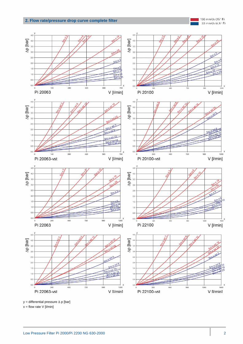
2. Flow rate/pressure drop curve complete filter
y = differential pressure ∆ p [bar]
x = flow rate V [l/min]

Low Pressure Filter Pi 2000/Pi 2200 NG 630-2000 3
3. Separation grade characteristics
y = beta-value
x = particle size [µm]
-
determined by multipass tests (ISO 16889)
calibration according to ISO 11171 (NIST)
_
4. Filter performance data
tested according to ISO 16889 (multipass test)
_
.
Sm-x elements with
max. ∆ p 20 bar
_
Sm-x vst elements with
max. ∆ p 210 bar
.
Sm-x 3 β5(C) ≥200 Sm-x vst 3 β5(C) ≥200
Sm-x 6 β7(C) ≥200 Sm-x vst 6 β7(C) ≥200
Sm-x 10 β10(C) ≥200 Sm-x vst 10 β10(C) ≥200
Sm-x 16 β15(C) ≥200 Sm-x vst 16 β15(C) ≥200
Sm-x 25 β20(C) ≥200 Sm-x vst 25 β20(C) ≥200
.
values guaranteed at
10 bar differential pressure
.
values guaranteed at
20 bar differential pressure
5. Quality assurance
MAHLE filter and filter elements are produced according to the following international standards:
Norm Designation
DIN ISO 2941 Hydraulic fluid power filter elements; verification of collapse/burst resistance
DIN ISO 2 942 Hydraulic fluid power filter elements; verification of fabrication integrity
DIN ISO 2 943 Hydraulic fluid power filter elements; verification of material compatibility
DIN ISO 3 723 Hydraulic fluid power filter elements; method for end load test
DIN ISO 3 724 Hydraulic fluid power filter elements; verification of flow fatigue characteristics
ISO 3 968 Hydraulic fluid power-filters-evaluation of pressure drop versus flow characteristics
ISO 10 771.1 Fatigue pressure testing of metal containing envelopes in hydraulic fluid applications
ISO 16 889 Hydraulic fluid power filters-multi-passmethod for evaluation filtration performance of a filter element
-
6. Symbols

Low Pressure Filter Pi 2000/Pi 2200 NG 630-2000 4
7. Order numbers
Example for ordering filters:
1. Housing design 2. Filter element
V =630 l/min and electrical maintenance indicator
Type: Pi 20063-69
Order number: 77965510
Sm-x vst 25
Type: Pi 75063 DN
Order number: 77961568
2 elements required for parallel arrangement
7.1 Housing design
Design
Nominal
size
NG
[l/min]
Order
number Type
no
options
with
bypass
valve
with
bypass
valve and
visual
indicator
with
bypass
valve and
electrical
indicator
with
visual
indicator
with
electrical
indicator
77965478 Pi 20063-060
77965486 Pi 20063-056
77965496 Pi 20063-057
77964497 Pi 20063-058
77965502 Pi 20063-068
630
77965510 Pi 20063-069
77965577 Pi 20100-060
77965585 Pi 20100-056
77965593 Pi 20100-057
77974769 Pi 20100-058
77965601 Pi 20100-068
Line
filter
single
1000
77965619 Pi 20100-069
77965387 Pi 22063-060
77965676 Pi 22063-056
77965684 Pi 22063-057
77965692 Pi 22063-058
77965700 Pi 22063-068
1260
77965718 Pi 22063-069
77965775 Pi 22100-060
77965783 Pi 22100-056
77965791 Pi 22100-057
77965809 Pi 22100-058
77965817 Pi 22100-068
Line
filter
parallel
2000
77965825 Pi 22100-069
When filter with non bypass configuration is selected, the collapse pressure of the element must not be exceeded.
Low Pressure Filter Pi 2000/Pi 2200 NG 630-2000 5
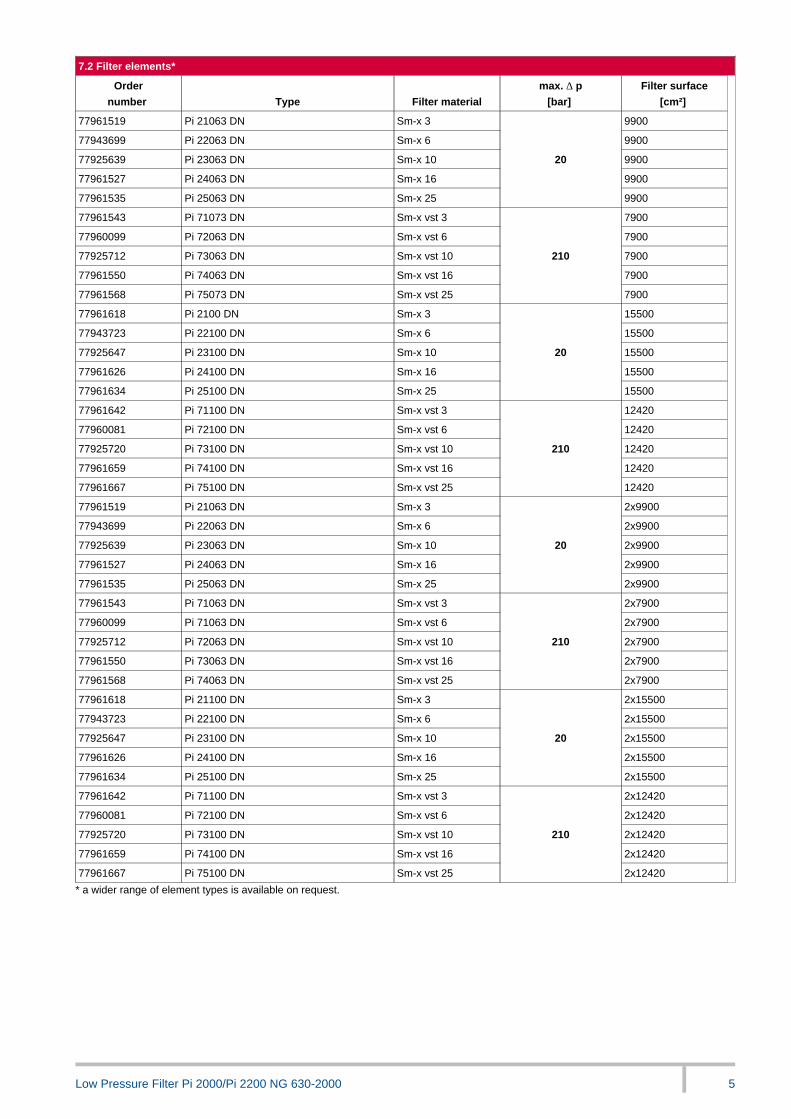
7.2 Filter elements*
Order
number Type Filter material
max. ∆ p
[bar]
Filter surface
[cm²]
77961519 Pi 21063 DN Sm-x 3 9900
77943699 Pi 22063 DN Sm-x 6 9900
77925639 Pi 23063 DN Sm-x 10 9900
77961527 Pi 24063 DN Sm-x 16 9900
77961535 Pi 25063 DN Sm-x 25
20
9900
77961543 Pi 71073 DN Sm-x vst 3 7900
77960099 Pi 72063 DN Sm-x vst 6 7900
77925712 Pi 73063 DN Sm-x vst 10 7900
77961550 Pi 74063 DN Sm-x vst 16 7900
77961568 Pi 75073 DN Sm-x vst 25
210
7900
77961618 Pi 2100 DN Sm-x 3 15500
77943723 Pi 22100 DN Sm-x 6 15500
77925647 Pi 23100 DN Sm-x 10 15500
77961626 Pi 24100 DN Sm-x 16 15500
77961634 Pi 25100 DN Sm-x 25
20
15500
77961642 Pi 71100 DN Sm-x vst 3 12420
77960081 Pi 72100 DN Sm-x vst 6 12420
77925720 Pi 73100 DN Sm-x vst 10 12420
77961659 Pi 74100 DN Sm-x vst 16 12420
77961667 Pi 75100 DN Sm-x vst 25
210
12420
77961519 Pi 21063 DN Sm-x 3 2x9900
77943699 Pi 22063 DN Sm-x 6 2x9900
77925639 Pi 23063 DN Sm-x 10 2x9900
77961527 Pi 24063 DN Sm-x 16 2x9900
77961535 Pi 25063 DN Sm-x 25
20
2x9900
77961543 Pi 71063 DN Sm-x vst 3 2x7900
77960099 Pi 71063 DN Sm-x vst 6 2x7900
77925712 Pi 72063 DN Sm-x vst 10 2x7900
77961550 Pi 73063 DN Sm-x vst 16 2x7900
77961568 Pi 74063 DN Sm-x vst 25
210
2x7900
77961618 Pi 21100 DN Sm-x 3 2x15500
77943723 Pi 22100 DN Sm-x 6 2x15500
77925647 Pi 23100 DN Sm-x 10 2x15500
77961626 Pi 24100 DN Sm-x 16 2x15500
77961634 Pi 25100 DN Sm-x 25
20
2x15500
77961642 Pi 71100 DN Sm-x vst 3 2x12420
77960081 Pi 72100 DN Sm-x vst 6 2x12420
77925720 Pi 73100 DN Sm-x vst 10 2x12420
77961659 Pi 74100 DN Sm-x vst 16 2x12420
77961667 Pi 75100 DN Sm-x vst 25
210
2x12420
* a wider range of element types is available on request.

Low Pressure Filter Pi 2000/Pi 2200 NG 630-2000 6
8. Technical specifications
Design: Flange filter
Nominal pressure: 25 bar (360 psi)
Test pressure: 32 bar (460 psi)
Temperature range: - 10 °C to + 120 °C
(other temperature ranges on request)
Bypass setting: ∆ p 3.5 bar ± 10 %
Filter head material: GAL
Filter housing material: AL
Sealing material: NBR/AL
Maintenance indicator setting: ∆ p 2.2 bar ± 0.3 bar
Electrical data of maintenance indicator:
Maximum voltage: 230 V ~/=
Maximum current: 2.5 A
Contact load: 60 VA / 40 W
Inrush current: 70 VA
Type of protection: IP 65 in inserted and
secured status
Contact: normally open/closed
Cable sleave: PG 11 Ø 6-10
-
If desired, electrical indicator may be supplied with lamp plug
connector or with pin-and-socket connector as per DIN 43651 part
2, 6-pole sleeve terminals and earthing, voltage 24 V=, wiring box
with 3 luminous diodes and transparent housing.
-
The electrical indicator function can be changed from the normally
open position to the normally closed position or vice versa by inver-
ting the electrical section.
Witch the inrush current of 70 VA the indicator can trigger small con-
tactors or contact relays.
Inductivity in the direct current may require the use of a signal eraser.
_.
Furter maintenance indicator details and designs are available in the
maintenance indicator data sheet.
.
When the acustic vent is used the permissible operating pressure
is 10 bar. The module design permits later extension from single to
twin or parallel filter.
_
Subject to technical alteration without prior notice.
_
*1 vent screw G 3/8
*2 drain plug G 3/4 DIN 910
9. Dimensions
All dimensions in mm.
Type A B C D E F G H
Weight
[kg]
Pi 20063 665 439 DN64 89 50.8 - 110 400 12.5
Pi 20100 885 669 DN64 89 50.8 - 110 630 15.0
Pi 22063 665 427.5 DN76 106 61.9 695 133 400 30.0
Pi 22100 885 6575 DN76 106 61.9 915 133 630 35.0
NPT- and SAE- connections on request.

Low Pressure Filter Pi 2000/Pi 2200 NG 630-2000 7
10. Installation, operating and maintenance instructions
10.1 Filter installation
When installing the filter make sure that sufficient space is available
to remove filter element and filter housing.
Preferably the filter should be installed with the filter housing pointing
downwards.
The maintenance indicator must be visible.
.
10.2 Connecting the electrical maintenance indicator
The electrical indicator is connected via a 2-pole appliance plug ac-
cording to DlN 43650 with poles marked 1 and 2.
The electrical section can be inverted to change from normally open
position to normally closed position or vice versa.
-
10.3 When should the filter element be replaced?
1 . Filters equipped with visual and electrical maintenance indica-
tor:
During cold starts, the indicator may give a warning signal.
Press the red button of the visual indicator once again only af-
ter operating temperature has been reached. If the red button
immediately pops up again and/or the electrical signal has not
switched off after reaching operating temperature. The filter ele-
ment must be replaced after the end of the shift.
2 . Filters without maintenance indicator:
The filter element should be replaced after trial run or flushing of
the system. Afterwards follow instructions of the manufacturer.
3 . Please always ensure that you have original MAHLE spare ele-
ments in stock: Disposable elements (SM-x) cannot be cleaned.
-
10.4 Element replacement
1 . Switch off system and relieve filter on pressure side.
2 . Open venting screw in filter cover (ascertain switching lever po-
sition with duplex filter and carefully check which filter housing
is under pressure).
3 . Remove drain plug in housing bottom and drain oil.
4 . Unscrew filter cover (CCW).
5 . Lift out filter element.
6 . Ckeck seal on filter cover. We recommend replacment in any
case.
7 . Make sure that the order number on the spare element corre-
sponds to the order number of the filter name-plate. Remove
packaging and place element closed end downward into filter
housing.
8 . Carefully insert element holding fixture of the filter cover into the
open end of the element and tighten cover against stop.
9 . Close drain plug on housing bottom.
10 . Carefully vent filter prior operation. Then thighten venting screw.
11. Spare parts list
Order numbers for spare parts
Position Type Order number
Seal kit for filter housing
(if duplex or parallel filter 2 sets)
NBR 77967433
FPM 77967441
EPDM 77967458
Seal kit for parallel unit
NBR 79350984
FPM 79350992
EPDM 79351008
Maintenance indicator
Visual PiS 3098/2,2 bar 77669971
Electrical PiS 3097/2,2 bar 77669948
Electrical upper part only 77536550
Seal kit for maintenance indicator
NBR 77760300
FPM 77760317
EPDM 77760325
Parallel unit (for parallel filter
modification) 77974876
Shift unit (for duplex filter modi-
fication Pi 2100) 77974868
Low Pressure Filter Pi 2000/Pi 2200 NG 630-2000 8
MAHLE Filtersysteme GmbH
Industriefiltration
Schleifbachweg 45
D-74613 Öhringen
Phone +49 (0) 7941/67-0
Fax +49 (0) 7941/67-23429
www.mahle-industriafiltration.com
79360611.04/2008


![High Pressure Filter Pi 420 - BIBUS Slovakia...High Pressure Filter Pi 420 up to NG 450 3 3. Separation grade characteristics y = beta-value x = particle-size [µm] _ determined by](https://cdn.vdocument.in/doc/165x107/5f0819e27e708231d420577f/high-pressure-filter-pi-420-bibus-slovakia-high-pressure-filter-pi-420-up.jpg)

![Line filter Pi 1907 - BIBUS · 2012. 10. 17. · Line filter Pi 1907 NG 400 - 6000 2 2. Separation grade characteristics y = beta-value x = particle size [µm]-determined by multipass](https://cdn.vdocument.in/doc/165x107/6146514c8f9ff81254203034/line-filter-pi-1907-bibus-2012-10-17-line-filter-pi-1907-ng-400-6000-2.jpg)


